WO2015181902A1 - Computer system and computer system control method - Google Patents
Computer system and computer system control method Download PDFInfo
- Publication number
- WO2015181902A1 WO2015181902A1 PCT/JP2014/064076 JP2014064076W WO2015181902A1 WO 2015181902 A1 WO2015181902 A1 WO 2015181902A1 JP 2014064076 W JP2014064076 W JP 2014064076W WO 2015181902 A1 WO2015181902 A1 WO 2015181902A1
- Authority
- WO
- WIPO (PCT)
- Prior art keywords
- data
- processor
- storage
- compressed
- server
- Prior art date
Links
Images


Classifications
-
- H—ELECTRICITY
- H04—ELECTRIC COMMUNICATION TECHNIQUE
- H04L—TRANSMISSION OF DIGITAL INFORMATION, e.g. TELEGRAPHIC COMMUNICATION
- H04L67/00—Network arrangements or protocols for supporting network services or applications
- H04L67/01—Protocols
- H04L67/06—Protocols specially adapted for file transfer, e.g. file transfer protocol [FTP]
-
- H—ELECTRICITY
- H04—ELECTRIC COMMUNICATION TECHNIQUE
- H04L—TRANSMISSION OF DIGITAL INFORMATION, e.g. TELEGRAPHIC COMMUNICATION
- H04L67/00—Network arrangements or protocols for supporting network services or applications
- H04L67/01—Protocols
- H04L67/10—Protocols in which an application is distributed across nodes in the network
- H04L67/1097—Protocols in which an application is distributed across nodes in the network for distributed storage of data in networks, e.g. transport arrangements for network file system [NFS], storage area networks [SAN] or network attached storage [NAS]
-
- G—PHYSICS
- G06—COMPUTING; CALCULATING OR COUNTING
- G06F—ELECTRIC DIGITAL DATA PROCESSING
- G06F12/00—Accessing, addressing or allocating within memory systems or architectures
- G06F12/02—Addressing or allocation; Relocation
- G06F12/08—Addressing or allocation; Relocation in hierarchically structured memory systems, e.g. virtual memory systems
- G06F12/10—Address translation
- G06F12/1081—Address translation for peripheral access to main memory, e.g. direct memory access [DMA]
-
- G—PHYSICS
- G06—COMPUTING; CALCULATING OR COUNTING
- G06F—ELECTRIC DIGITAL DATA PROCESSING
- G06F15/00—Digital computers in general; Data processing equipment in general
- G06F15/16—Combinations of two or more digital computers each having at least an arithmetic unit, a program unit and a register, e.g. for a simultaneous processing of several programs
- G06F15/163—Interprocessor communication
- G06F15/173—Interprocessor communication using an interconnection network, e.g. matrix, shuffle, pyramid, star, snowflake
- G06F15/17306—Intercommunication techniques
- G06F15/17331—Distributed shared memory [DSM], e.g. remote direct memory access [RDMA]
-
- G—PHYSICS
- G06—COMPUTING; CALCULATING OR COUNTING
- G06F—ELECTRIC DIGITAL DATA PROCESSING
- G06F3/00—Input arrangements for transferring data to be processed into a form capable of being handled by the computer; Output arrangements for transferring data from processing unit to output unit, e.g. interface arrangements
- G06F3/06—Digital input from, or digital output to, record carriers, e.g. RAID, emulated record carriers or networked record carriers
-
- H—ELECTRICITY
- H04—ELECTRIC COMMUNICATION TECHNIQUE
- H04L—TRANSMISSION OF DIGITAL INFORMATION, e.g. TELEGRAPHIC COMMUNICATION
- H04L67/00—Network arrangements or protocols for supporting network services or applications
- H04L67/01—Protocols
Definitions
- the present invention relates to a computer system and a computer system control method.
- connection bandwidth between the server and the storage needs to be wider.
- the system of Patent Document 1 connects a server computer and a storage device by FC (Fibre Channel).
- FC Fibre Channel
- the system of Patent Document 1 is equipped with a flash memory drive for data cache on the server side, and it is possible to reduce storage access by performing hit miss determination of read data. For this reason, it is necessary to prepare a flash on the server side and manage the cache area by the server. Further, in order to determine whether the compressed data on the server side should be read without being decompressed, a policy is set in advance for each object, and information on whether the data storage area is compressed is set on the server side. Need to manage. Furthermore, in the case of a cache miss, the storage data is temporarily stored in the flash memory before being transferred to the server-side memory, and the server processing cost due to the decompression processing of the compressed data is high, resulting in the decompression processing load other than the path bandwidth. Can cause system performance to degrade.
- this application eliminates the need for advance design on the application side, and implements separate use of decompressed and non-stretched leads according to the I / O characteristics, thereby effectively transferring data between server storages.
- the purpose is to reduce the amount of data and increase the effective bandwidth between server storages.
- a computer system includes a storage module including a storage processor, a storage memory, and a storage device, a server module including a server processor and a server memory, a server processor, and a storage. And an interface device connected to the processor.
- the interface device When the interface device is located in the server module and receives a read request issued by the server processor, the interface device transmits a read command based on the read request to the storage processor, and converts the target data of the read request from the storage processor.
- the reverse conversion instruction to cause the interface device to perform reverse conversion of the obtained target data after conversion, on the server memory while performing reverse conversion on the target data after conversion stored at the transfer source address on the storage memory DMA (Direct Memory Access) to transfer to the destination address.
- DMA Direct Memory Access
- the structure of the server storage system of an Example is shown.
- the structure of the server storage system of a 1st example is shown.
- the structure of the server storage system of a 2nd example is shown.
- the structure of the server storage system of a 3rd example is shown.
- the structure of the server storage system of a 4th example is shown.
- the structure of a virtual server storage system is shown.
- the structure of the server storage system of a modification is shown.
- the structure of SS connection mechanism is shown.
- the structure of a DMA controller is shown.
- the structure of a compression storage device is shown.
- the structure of the storage area in the ST memory is shown.
- the structure of the storage area in a physical device is shown. 1 shows a configuration of a storage area in a storage system.
- a virtual volume management table is shown.
- a storage pool management table is shown. 7 shows a RAID group management table.
- a physical device management table is shown.
- a virtual page management table is shown.
- a real page management table is shown.
- An empty real page management table is shown.
- the structure of the storage area in a physical device is shown.
- a compression management table is shown. An operation in which the ST controller acquires compressed information from the compressed storage device will be described. A first operation in which the ST controller acquires compressed data from the compressed storage device will be described. The second operation in which the ST controller acquires compressed data from the compressed storage device will be described.
- a third operation in which the ST controller acquires compressed data from the compressed storage device will be described.
- extension DMA process is shown.
- the compression information SGL is shown. Indicates the data format.
- the first process in the read process of the SS system is shown.
- the 2nd process following the 1st process in the read process of SS system is shown.
- extension DMA process by SS connection mechanism is shown.
- the second process following the first process in the decompression DMA process by the SS connection mechanism is shown.
- the first process in the security code check process during the decompression DMA process will be described.
- the second process following the first process in the security code check process during the decompression DMA process is shown.
- a third process following the second process in the security code check process during the decompression DMA process will be described.
- the first process in the write process of the SS system is shown.
- the 2nd process following the 1st process in the write process of SS system is shown.
- the third process following the second process in the write process of the SS system is shown.
- the 1st process in the compression DMA process by SS connection mechanism is shown.
- the 2nd process following the 1st process in the compression DMA process by SS connection mechanism is shown.
- a compression offload write process is shown.
- the first process in the read process when performing decryption by the server and decompression by the SS connection mechanism is shown.
- the second process after the first process in the read process when performing decryption by the server and decompression by the SS connection mechanism is shown.
- the configuration of the server-server connection is shown.
- the configuration of storage-storage connection is shown.
- aaa table such as “aaa list”, “aaaDB”, “aaa queue”, etc.
- the information is a data structure such as a table, list, DB, queue, etc. It may be expressed in other than. Therefore, “aaa table”, “aaa list”, “aaaDB”, “aaa queue”, etc. may be referred to as “aaa information” to indicate that the information does not depend on the data structure.
- program is used as the subject.
- the program performs processing determined by being executed by the processor using the memory and communication port (communication control device)
- the processor is used as the subject.
- the explanation may be as follows. Further, the processing disclosed with the program as the subject may be processing performed by a computer such as a storage controller or an information processing apparatus. Further, part or all of the program may be realized by dedicated hardware.
- various programs may be installed in each computer by a program distribution server or a computer-readable memory media.
- the program distribution server includes a processor (for example, CPU: Central Processing Unit) and a storage resource, and the storage resource further stores a distribution program and a program to be distributed.
- the distribution program is executed by the CPU, the CPU of the program distribution server distributes the distribution target program to other computers.
- SS server storage
- FIG. 1 shows the configuration of the server storage system of the embodiment.
- This SS system includes a server 100 and a storage system 300.
- the server 100 and the storage system 300 may be stored in one housing.
- the SS system is sometimes called a computer system.
- the server 100 includes a server (SV) memory 110, a server (SV) processor 120, and a server storage (SS) connection mechanism 200.
- the SV memory 110 and the SV processor 120 are connected to each other via an internal bus.
- the SV memory 110 is a memory, and stores a program and data for controlling the server 100 such as an application, an OS (Operating System), and a driver.
- the SV processor 120 is a microprocessor and executes processing according to a program in the SV memory 110.
- the SS connection mechanism 200 is connected to the SV processor 120 via the server-side bus and is connected to the storage system 300 via the storage-side bus, and controls communication between the SV processor 120 and the storage system 300.
- the SV processor 120 and the SS connection mechanism 200 are connected by a server-side bus.
- the SS connection mechanism 200 and the ST processor 420 are connected by a storage-side bus that is the same type of bus as the server-side bus.
- PCI Express PCI Express
- Each of the server side bus and the storage side bus may be a substrate such as a backplane or a cable.
- DMA transfer between the storage areas of the server 100 and the storage system 300 can be performed by connecting the server 100 to the storage system 300 through the same bus as the internal bus of the server 100, and the request issued from the SV processor 120
- the storage (ST) processor in the storage system 300 activates the DMA engine installed in the SS connection mechanism 200, and the data on the ST memory in the storage system 300 is transferred to the SV memory 110 or the SV memory 110.
- ST memory are transferred to the ST memory in the storage system 300.
- the server 100 may include an FM with a compression / decompression function, which is a flash memory (FM) having a compression / decompression function.
- the server 100 may include a Root Complex (RC) connected to the SV processor 120 via an internal bus and connected to the SS connection mechanism 200 via a server-side bus.
- RC Root Complex
- the SS connection mechanism 200 compresses the write data from the server 100 and transfers it to the storage system 300, decompresses the read data from the storage system 300 and transfers it to the server 100.
- the storage system 300 includes a storage (ST) controller 400 and a storage device 500.
- the storage device 500 stores data accessed from the server 100.
- the ST controller 400 is connected to the storage device 500 and the server 100 and controls access to the storage device 500.
- the ST controller 400 may be referred to as a controller.
- the ST controller 400 includes a storage (ST) memory 410, a storage (ST) processor 420, and a drive interface (I / F) 430.
- the ST memory 410, the ST processor 420, and the drive I / F 430 are connected to each other via an internal bus.
- the ST memory 410 is a memory and stores a program and data for controlling the storage system 300.
- the ST processor 420 is a microprocessor, is connected to the SS connection mechanism 200 via a storage-side bus, and executes processing according to a program stored in the ST memory 410.
- the drive I / F 430 is connected to the storage device 500 via the storage device side bus and controls communication between the ST processor 420 and the storage device 500.
- the ST controller 400 may include an FM with a compression / decompression function.
- the ST processor 420 can compress and expand the cached data using the FM with compression / decompression function as a cache area.
- the ST controller 400 may include an RC connected to the ST processor 420 via an internal bus and connected to the SS connection mechanism 200 via a storage-side bus.
- the storage device 500 includes a plurality of storage devices 600 (# 0, # 1, # 2, # 3).
- the physical storage device 600 may be called a physical device, and the virtual storage device may be called a virtual device.
- a physical device including the data compression / decompression function may be referred to as a compressed storage device 600a, and a physical device not including the data compression / decompression function may be referred to as an uncompressed storage device 600b.
- compression and decoding of data may be performed by the compression storage device 600a, the ST controller 400, or the server 100.
- compression in the SS system can be replaced with other transformations such as deduplication.
- conversion result data is generated from the original data.
- the size of the conversion result data is smaller than the size of the original data.
- original data is generated from the conversion result data by inverse conversion.
- the inverse transform for compression is decompression.
- the inverse transformation for deduplication is the restoration of the original data.
- FIG. 2 shows the configuration of the server storage system of the first specific example.
- Each SS connection mechanism 200 may be directly connected to a plurality of ST controllers 400.
- the SS system of the first specific example includes a plurality of servers 100 and one storage system 300.
- the storage system 300 includes two ST controllers 400.
- Each ST controller 400 includes two ST processors 420, a plurality of ST memories 410 connected to each ST processor 420, and a plurality of drive I / Fs 430 connected to each ST processor 420.
- the two ST processors 420 in one ST controller 400 are respectively connected to the two ST processors 420 in the other ST controller 400 via the inter-ST controller 400 bus.
- a plurality of ST processors 420 may be provided. In the case of a plurality of ST controllers, each ST processor 420 in the other ST controller 400 is connected to each other via an inter-ST controller bus.
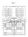
- FIG. 3 shows the configuration of the server storage system of the second specific example.
- Each SS connection mechanism 200 may be connected to a plurality of ST controllers 400 via the interface expansion device 700.
- the SS system of the second specific example includes a plurality of servers 100 and an interface expansion device 700 connected to each ST controller 400.
- the interface expansion device 700 performs control to increase the number of connection paths between the server 100 and the ST controller 400. With the interface expansion device 700, more servers 100 can be directly connected to one storage.
- the interface expansion device 700 is, for example, a PCIe switch.
- FIG. 4 shows the configuration of the server storage system of the third specific example.
- Each server 100 may include a plurality of SS connection mechanisms 200.
- each server 100 includes two SS connection mechanisms 200.
- the two SS connection mechanisms 200 are connected to the two ST controllers 400 via the interface expansion device 700, respectively.
- the storage side bus and the server side bus can be balanced by setting the storage side bus to two PCIex4 and the server side bus to one PCIex8.
- the storage side bus by changing the storage side bus to one PCIex4 and the server side bus to one PCIex8, only the bandwidth of the storage side bus is changed to 1 ⁇ 2.
- the compressed data transferred from the storage-side bus to the SS connection mechanism 200 is decompressed by the SS connection mechanism 200 and transferred to the server-side bus
- the data that has been compressed to 1 ⁇ 2 in the storage-side bus is Even if the server-side bus returns to the original size data, the storage-side bus and the server-side bus can secure their respective bandwidths.
- each server 100 includes two SS connection mechanisms 200, thereby ensuring hardware redundancy.
- Each server 100 may include one SS connection mechanism 200, and the bandwidth of the server side bus may be set wider than that of the storage side bus in consideration of the compression rate.
- the storage side bus may be two PCIex4, and the server side bus may be one PCIex16.
- the same effect can be obtained even if the storage side bus is two PCIex4 and the server side bus is two PCIex8. In this way, the server-side bus and the storage-side bus can be assigned the necessary bandwidth according to the compression, according to PCIe.
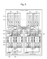
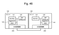
- FIG. 5 shows the configuration of the server storage system of the fourth specific example.
- the SS system may include a plurality of storage systems 300.
- the SS system includes two storage systems 300.
- the two SS connection mechanisms 200 in one server 100 are connected to the two storage systems 300 via the interface expansion device 700, respectively.
- One SS connection mechanism 200 is connected to two ST controllers 400 in one storage system 300 via the interface expansion device 700.
- this configuration by installing two SS connection mechanisms 200 in the server 100, more storage systems 300 can be connected to the server 100, and broadband and high-performance storage resources can be provided to the server 100. .
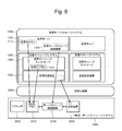
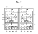
- FIG. 6 shows the configuration of the virtual server storage system.
- the physical SS system 2000 may execute the virtualization mechanism 3000 and execute the virtual server storage (SS) system 1000 on the virtualization mechanism 3000.
- the virtual SS system 1000 includes a virtual server 1100 and a virtual storage system 1300.
- the SS system 2000 physically includes at least a processor 2020, a memory 2010, a storage device 2500, and an SS connection mechanism 2200.
- the virtual server 1100 provides the same function as the server 100. More specifically, the virtual server 1100 includes a virtual SV memory 2110 that provides the same function as the SV memory 110 and a virtual SS connection mechanism 1200 that provides the same function as the SS connection mechanism 200.
- the virtual storage system 1300 includes a virtual ST controller 1400 that provides the same functions as the ST controller 400 and a virtual storage device 1500 that provides the same functions as the storage device 500.
- the virtual ST controller 1400 includes a virtual ST memory 1410 that provides the same functions as the ST memory 410.
- the virtualization mechanism 3000 assigns the storage area in the memory 2010 to the virtual SV memory 1110, assigns the processing capacity of the SS connection mechanism 2200 to the virtual SS connection mechanism 1200, assigns the storage area in the memory 2010 to the virtual ST memory 1410, A storage area in the storage device 2500 is allocated to the virtual storage device 1500.
- the virtual SS system 1000 may be executed on a computer system having another configuration such as a single server or a server and storage system.
- the computer system may include a compression / decompression circuit instead of the SS connection mechanism.
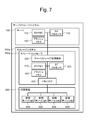
- FIG. 7 shows a configuration of a modified server storage system.
- the SS system includes a storage system 300a instead of the storage system 300, and includes an ST controller 400a instead of the ST controller 400.
- the SS connection mechanism 200 is provided in the ST controller 400a.
- the SS connection mechanism 200 is connected to the SV processor 120 in the server 100 and is connected to the ST processor 420 in the ST controller 400a.
- the server 100 may further include an FM 140.
- the FM 140 may have a compression / decompression function, and may perform compression / decompression in accordance with an instruction from the SV processor 120.
- the ST controller 400a may further include an FM 440.
- the FM 440 may have a compression / decompression function, and may perform compression or expansion instead of the SS connection mechanism 200 in response to an instruction from the ST processor 420.
- the write operation is performed by the FM 140 before the data is sent to the SS connection mechanism 200 in the flow disclosed in FIGS.
- the SS connection mechanism 200 reads out and decompresses this compressed data, and further writes it into the storage device 600 via the ST memory 410 while recompressing it into the compression format of the storage system 300 of this embodiment.
- the SS connection mechanism 200 may further compress the compressed data into the compression format of the storage system 300 of this embodiment without expanding the compressed data when it is read. With this configuration, the write band can be widened.
- the read operation is performed when the SS connection mechanism 200 reads the data compressed by the FM 440 in the ST controller 400a or the data compressed and stored in the storage device 600 in the flow disclosed in FIGS.
- the DMA transfer is performed with the FM 140 or the SV memory 110 on the server 100 side while recompressing the compressed format of the server 100 above.
- the SS connection mechanism 200 realizes a broadband system in cooperation with the FM 440 having a compression / decompression function.
- the SS connection mechanism 200 may be provided in the server 100, may be provided in the ST controller 400, or may be provided between the server 100 and the ST controller 400.
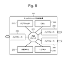
- FIG. 8 shows the configuration of the SS connection mechanism 200.
- the SS connection mechanism 200 is implemented as, for example, an ASIC (application specific integrated circuit).
- the SS connection mechanism 200 includes an IF (Interface) processor 210, a DMA (Direct Memory Access) controller 220, an internal memory 230, a register 240, an interface 250, two interfaces 260, and an internal switch 270.
- the DMA controller 220 may be called DMA.
- the IF processor 210, the DMA controller 220, the internal memory 230, the register 240, the interface 250, and the two interfaces 260 are connected to each other via an internal switch 270.
- One interface 250 is connected to the SV processor 120 via a server-side bus.
- the other two interfaces 260 are connected to the two ST processors 420 via storage-side buses, respectively.
- the internal memory 230 is a memory and stores programs and data.
- the IF processor 210 is a microprocessor and executes processing according to a program in the internal memory 230.
- the DMA controller 220 executes data transfer (transfer between memories) according to an instruction from the IF processor 210.
- the register 240 stores a setting value of the IF processor 210.
- the internal switch 270 controls communication between the units in accordance with instructions from the IF processor 210. Note that there may be a plurality of SV side interfaces and ST side interfaces, and they may be connected to the SV processor 120 and the ST processor 420 via each bus and interface expansion.
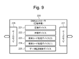
- FIG. 9 shows the configuration of the DMA controller 220.
- the DMA controller 220 includes a compression device 221, an expansion device 222, a guarantee code processing device (0) 224, a guarantee code processing device (1) 224, a data transfer control device 225, and two interfaces 226 and 227. Including. The two interfaces are connected to an internal switch.
- the compression device 221 compresses uncompressed data and converts it into compressed data.
- the decompression device 222 decompresses the compressed data and converts it into uncompressed data.
- the guarantee code processing device (0) 223 calculates a guarantee code for uncompressed data, and adds a guarantee code to the uncompressed data. Further, the guarantee code processing device (0) 223 detects an error in the non-compressed data based on the non-compressed data and the guarantee code.
- the guarantee code processing device (1) calculates a guarantee code for the compressed data and adds the guarantee code to the compressed data. Furthermore, the guarantee code processing device (1) 224 detects an error in the compressed data based on the compressed data and the guarantee code. Each security code processing device also deletes the security code.
- the data transfer control device 225 controls data transfer.
- DMA transfer can be performed between the SV memory 110 in the server 100 and the ST memory 410 of the ST controller 400.
- Data compression or decompression can be performed.
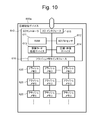
- FIG. 10 shows the configuration of the compressed storage device 600a.
- the compressed storage device 600 a includes a storage device (SD) controller 610 and a plurality of flash memories (FM) 620 connected to the SD controller 610.
- the SD controller 610 includes a RAM (Random Access Memory) 611, a physical device (SD) processor 612, a guarantee code processing device 613, a compression / decompression device 614, an I / O interface 615, and an FM interface 616.
- Each unit in the SD controller 610 is connected to each other via an internal bus.
- the I / O interface 615 is connected to the drive I / F 430 of the ST controller 400 via the storage device side bus.
- the RAM 611 is a DRAM (Dynamic RAM), for example, and stores programs and data.
- the SD processor 612 is a microprocessor and executes processing according to a program stored in the RAM 611.
- the security code processing device 613 generates a security code based on the data, adds a security code to the data, checks the data based on the data and the security code, and detects an error. The security code is also deleted.
- the compression / decompression device 614 compresses the uncompressed data and converts it into compressed data, and decompresses the compressed data and converts it into uncompressed data.
- the FM interface 616 is connected to a plurality of FMs 620.
- the compressed storage device 600a may perform compression or expansion in place of the SS connection mechanism 200 in response to an instruction from the ST processor 420. Further, the compression storage device 600a may compress the data by internal determination with respect to the data input, and may decompress and output the internally compressed data unless there is a specific instruction from the ST processor 420. .
- FIG. 11 shows the configuration of the storage area in the ST memory 410.
- the storage area in the ST memory 410 includes a virtual volume management table 810, a storage pool management table 820, a RAID group management table 830, a physical device management table 840, a virtual page management table 850, and a real page management table 860. And a free real page management table 870. These tables will be described later.
- the storage area in the ST memory 410 further includes a storage (ST) cache area 880 and a storage (ST) buffer area 890.
- the ST cache area 880 temporarily holds write data and read data, and is used for data hits for write and read access.
- the ST buffer area 890 stores data and control information transmitted / received by the ST controller 400.
- FIG. 12 shows the configuration of the storage area in the compressed storage device 600a.
- the storage area in the compressed storage device 600a includes a metadata area 910, a cache area 930, a buffer area 940, and a data area 950 in the FM 620 in the RAM.
- the metadata area 910 stores metadata and includes a compression management table 920.
- the cache area 930 stores temporary data.
- the buffer area 940 stores data and control information transmitted / received by the compressed storage device 600a.
- the data area 950 stores data. Note that the information in the RAM 611 in the SD controller 610 may be in the connected FM 620.
- FIG. 13 shows the configuration of the storage area in the storage system 300.
- the ST controller 400 allocates a storage area in the physical device to the virtual device.
- the physical device may be either a compressed storage device 600a (compressed SD) or an uncompressed storage device (uncompressed SD).
- the ST controller 400 creates a parity group using a plurality of virtual devices.
- the parity group may be either a compressed parity group using a plurality of virtual devices based on a plurality of compressed storage devices 600a or an uncompressed parity group using a plurality of virtual devices respectively based on a plurality of uncompressed storage devices. good.
- the ST controller 400 uses the storage pool management table 820 to allocate storage areas in the parity group to the storage pool.
- the ST controller 400 uses the virtual volume management table 810 to allocate a storage area in the storage pool to the virtual volume.
- each storage pool there may be a compressed storage pool for storing compressed data and an uncompressed storage pool for data stored without being compressed.
- the compressed storage pool may be provided by, for example, a compressed parity group including a storage area of a functional device having a compression function, and storage in the pool is connected to the ST controller 400 or the ST controller 400. It may be configured to be compressed by a compression mechanism.
- the virtual volume can also be a compressed virtual volume in which written data is compressed and stored in the storage area, and an uncompressed virtual volume in which the written data is stored in the storage area without being compressed. You may do it.
- the ST controller 400 provides the virtual volume to the server 100.
- FIG. 14 shows the configuration of pages in the storage system 300.
- Parity group includes multiple real pages.
- the virtual volume includes a plurality of virtual pages.
- the ST controller 400 uses the real page management table 860 to assign real pages to virtual pages.
- the total size of real pages allocated to virtual pages can be made larger than the total size of physical devices.
- the ST controller 400 can switch between a real page in the compressed parity group and a real page in the non-compressed parity group and assign it to the virtual page. Thereby, the presence or absence of the compression effect can be switched.
- the total size of real pages allocated to virtual pages is set to the same size as the total size of physical devices, the utilization rate is reduced without increasing the capacity of the FM 620, and the life of the FM 620 is extended. You can also.
- FIG. 15 shows the virtual volume management table 810.
- the virtual volume management table 810 includes an entry for each virtual volume.
- An entry corresponding to one virtual volume includes a volume number (#), a volume capacity, an allocated capacity, a pool number (#), and a volume attribute.
- the volume number is an identifier indicating the virtual volume.
- the volume capacity is the capacity of the virtual volume.
- the allocated capacity is the total size of virtual pages to which real pages are allocated in the virtual volume.
- the pool number is an identifier indicating a storage pool including a real page that can be allocated to the virtual volume.
- the volume attribute indicates the presence or absence of compression in the virtual volume.
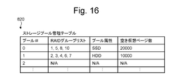
- FIG. 16 shows the storage pool management table 820.
- the storage pool management table 820 includes an entry for each storage pool.
- the entry corresponding to one storage pool includes a pool number (#), a RAID (Redundant Arrays of Inexpensive Disks) group list, a pool attribute, and the number of free virtual pages.
- the pool number is an identifier indicating the storage pool.
- the RAID group list is an identifier indicating a RAID group included in the storage pool.
- the pool attribute indicates the type of physical device used for the storage pool.
- the number of free virtual pages indicates the number of free virtual pages in the storage pool.
- FIG. 17 shows the RAID group management table 830.
- the RAID group management table 830 includes an entry for each RAID group.
- An entry corresponding to one RAID group includes a RAID group number (#), a RAID level, and a physical device number (#).
- the RAID group number is an identifier indicating the RAID group.
- the RAID level indicates the RAID level of the RAID group.
- the physical device number is an identifier indicating a physical device used for the RAID group.
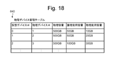
- FIG. 18 shows the physical device management table 840.
- the physical device management table 840 includes an entry for each physical device.
- the entry corresponding to one physical device includes a virtual device number (#), a physical device number (#), a physical capacity, a logical usage capacity, and a physical usage capacity.
- the virtual device number is an identifier indicating a virtual device to which the physical device is assigned.
- the physical device number is an identifier indicating the physical device.
- the physical capacity is the capacity of the physical device.
- the logical usage capacity is the usage amount of the logical storage area of the virtual device.
- the physical usage capacity is the usage amount of the physical storage capacity of the physical device.
- FIG. 19 shows a virtual page management table 850.
- the virtual page management table 850 is created for each virtual page.
- the virtual page management table 850 corresponding to one virtual page includes a virtual volume number (#), a real page pointer, and a page attribute.
- the virtual volume number is an identifier indicating a virtual volume including the virtual page.
- the real page pointer is a pointer that points to a real page assigned to the virtual page.
- the page attribute indicates whether the actual page stores compressed data or non-compressed data.
- the upper virtual page management table 850 indicates a virtual page to which a real page is allocated, and a real page pointer points to the real page.
- the lower virtual page management table 850 indicates a virtual page to which no real page is allocated, and the real page pointer indicates NULL.
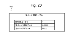
- FIG. 20 shows the real page management table 860.
- the real page management table 860 is created for each real page.
- the real page management table 860 corresponding to one real page includes a RAID group number (#), a real page head address, and a free page pointer.
- the RAID group number is an identifier indicating a RAID group including the real page.
- the real page head address indicates the head address of the real page in the RAID group.
- the free page pointer points to the real page management table 860 of the next free real page when the real page is a free real page.
- FIG. 21 shows a free real page management table 870.
- the free real page management table 870 includes a free page management pointer. This empty page management pointer points to the actual page management table 860 for empty pages. The empty page pointer in the real page management table 860 of the last empty page of consecutive empty pages indicates the empty page management pointer.
- FIG. 22 shows the configuration of the storage area in the physical device.
- the compression storage device 600a stores the compression management table 920 in the RAM 611 or the FM 620.
- the SD controller 610 of the compressed storage device 600a provides the ST controller 400 with a logical address in units of blocks in the storage area, and assigns real addresses in units of blocks to the logical addresses using the compression management table 920.
- the block unit shown here indicates a data unit of block storage.
- the compression storage device 600a determines whether or not compression is possible in a unit in which a plurality of blocks are grouped in terms of non-compressed data (for example, 8 kB in which a plurality of block sizes of 0.5 kB are grouped, hereinafter compression unit). Compress uncompressed data for each compression unit.
- the uncompressed storage device stores the real address management table in the RAM.
- the SD controller 610 of the uncompressed storage device provides a logical address for each block to the ST controller 400, and assigns a real address of the block to the logical address using the real address management table.
- FIG. 23 shows the compression management table 920.
- the compression management table 920 is stored in the RAM 611 or FM 620 in the storage device 600 for each storage device 600.
- the compression management table 920 is stored in the HDD.
- the compression management tables 920 of a plurality of storage devices 600 may be collected and stored in the ST memory 410 of the storage controller or the flash memory of the storage controller for management.
- the compression management table 920 includes an entry for each compression unit in the compression storage device 600a.
- An entry corresponding to one compression unit includes a logical address, a real address, a compression flag, and the number of blocks after compression.
- the logical address indicates the first logical address of the compressed data.
- the real address indicates the first real address of the compression unit.
- the compression flag indicates whether data in the compression unit is compressed.
- the number of blocks after compression indicates the number of blocks for the compressed data of the uncompressed data. Here, when all the blocks in the compression unit are non-compressed data, the number of blocks after compression is the maximum block number. When the compression unit includes a compression block, the number of compression blocks is smaller than the maximum block number.
- FIG. 23 shows a case where the 8 KB compression unit is 8 KB compressed data. At this time, it is determined by the compression flag whether the corresponding 8 KB is compressed data.
- FIG. 24 shows a first operation in which the ST controller 400 acquires compressed information from the compressed storage device 600a.
- Compression information is information related to compression of target data stored in the compression storage device 600a.
- the ST controller 400 issues a compression information request for acquiring the compression information of the target data to the compression storage device 600a.
- the compression storage device 600a reads the compression information of the target data from the compression management table 920 in response to the compression information request, and issues a compression information response indicating the compression information to the ST controller 400.
- the compression information indicates the compression state of the target data.
- the compression information request includes a command code indicating that the compression information is requested, an identifier of the request, an address that is a logical address of the target data in the compression storage device 600a, and a request size that is the size of the target data. Including.
- the compressed information response is obtained by decompressing the corresponding compressed information request identifier, the compressed overall size of the compressed unit group including the target data, and the first compressed unit of the compressed unit group including the target data.
- the first offset position which is an offset from the beginning of the decompressed data to the beginning of the target data.
- the compression information response includes, for each compression unit in the compression unit group, a compression presence / absence flag indicating the presence / absence of compression of the compression unit, and a post-compression block number indicating the number of blocks in the compression unit after compression. .
- the ST controller 400 determines that the number of blocks after compression is the same as the number of blocks before compression, the ST controller 400 determines non-compression, and when the number of blocks after compression differs from the number of blocks before compression, the compression presence / absence flag is unnecessary It is also good.
- the ST controller 400 can acquire compression information of data compressed by other than the ST controller 400, such as the compression storage device 600a and the SS connection mechanism 200.
- the ST controller 400 can obtain the compression information necessary for decompression by sending the compression information to other parts in the SS system even if the part is a part other than the part where the compression is performed.
- the ST controller 400 reads the compressed data distributed and stored in the plurality of compressed storage devices 600a in the order of logical addresses, and acquires the compression information from the respective compressed storage devices 600a, whereby a plurality of compressed storages are obtained.
- the compressed data stored in the device 600a can be rearranged so as to be continuously stored in the ST memory 410.
- the ST controller 400 uses SGL for rearrangement and is logically continuous, and may not be physically continuous.
- the SS connection mechanism 200 can sequentially read the compressed data from the ST memory 410.
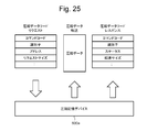
- FIG. 25 shows an operation in which the ST controller 400 acquires compressed data from the compressed storage device 600a.
- the compressed storage device 600a compresses and stores the data received from the ST controller 400
- the compressed storage device 600a generates uncompressed data by expanding the compressed data in response to a normal read request, and sends the uncompressed data to the ST controller 400. Can be sent.
- the ST controller 400 issues a compressed data read request to the compressed storage device 600a in order to acquire target data stored in the compressed storage device 600a as compressed data.
- the compressed storage device 600a reads the compressed data in response to the compressed data read request, transmits the compressed data of the target data, and issues a compressed data read response indicating the read result to the ST controller 400.
- the compressed data read request is a command code for instructing to read compressed data as it is compressed, an identifier of the request, an address that is a logical address of the target data in the compressed storage device 600a, and a size of the target data. Including request size. Note that the value acquired by the above-described compression information read is used as the size of the target data.
- the compressed data read response includes an identifier of the corresponding compressed data read request, a status related to the read processing, and a transfer size indicating the size of the target data transferred to the ST controller 400.
- the ST controller 400 can acquire the compressed data of the target data without decompressing it with the compressed storage device 600a. Thereby, the bandwidth of the bus between the compressed storage device 600a and the ST controller 400 and the amount of bandwidth used in the ST controller 400 can be reduced.
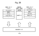
- the compression information is acquired by using the second operation shown in FIG. 26 as a method for the ST controller 400 to acquire the compression information and the compressed data with a single request.
- the compressed data is read at the beginning or end of the compressed data when sent, or the compressed data read response is added as in the third operation shown in FIG. It is also good.
- only the compressed data read is performed without performing the compression information read, and the data size before compression is set as the target data size of the compressed data read request.
- the data size after compression is set as the size of the target data of the compressed read response corresponding to this request.
- the ST controller 400 When receiving the compressed read response, the ST controller 400 acquires the compressed data size from the compressed information read together with the compressed data, and compares it with the transferred size of the compressed read response. Even when a transfer size underflow error occurs, it is determined that the transferred data has been transferred by the data size after compression, and the transfer is determined to be normal. After this, expanded DMA transfer is carried out, and the final transfer data consistency is determined by checking the security code in the DMA transfer.
- the compressed read response can be implemented with an auto response. It also reduces performance overhead due to an increase in the number of requests by combining compressed information acquisition and compressed data acquisition requests at once.
- FIG. 28 shows an operation between the ST controller 400 and the SS connection mechanism 200 in the decompression DMA process.
- the ST controller 400 can issue a decompression DMA request for instructing decompression DMA processing to the SS connection mechanism 200.
- the decompression DMA process is a process of reading the compressed data of the target data from the designated memory, decompressing the compressed data to generate uncompressed data, and writing the uncompressed data to the designated memory.
- the decompression DMA processing reads the compressed data of the target data from the ST memory 410 in the ST controller 400, decompresses the compressed data to generate uncompressed data, and sends the uncompressed data to the SV memory 110 in the server 100. Write.
- the SS connection mechanism 200 reads compressed information SGL which is SGL (Scatter / Gather List) indicating information related to compressed data in the ST memory 410 based on the decompressed DMA request. Further, the SS connection mechanism 200 reads the compressed data from the storage area indicated by the compression information SGL in the ST memory 410. Further, the SS connection mechanism 200 decompresses the compressed data, writes the uncompressed data to the SV memory 110, and then issues a decompressed DMA response to the ST controller 400.
- the compression information SGL is a list that sequentially indicates the addresses and sizes of the plurality of compressed data in the ST memory 410 when a plurality of compressed data stored in a distributed manner in the storage system 300 is read to the ST memory 410. It is.
- the compressed data when compressed data is stored in a RAID group, the compressed data is distributed and stored in the ST memory 410.
- the SS connection mechanism 200 can read the compressed data sequentially by following the compression information SGL, and can sequentially decompress and write the compressed data to the SV memory 110. As a result, the performance can be improved as compared with the case where each unit stored in a distributed manner is expanded and transferred.
- the decompression DMA request is added to a command code indicating decompression DMA processing, an identifier indicating a read request from the server 100 that is the basis of the decompression DMA request, parameters such as compression of the target data, and uncompressed data of the target data.
- Uncompressed security code information indicating the security code compressed security code information indicating the security code added to the compressed data of the target data, uncompressed transfer length indicating the length of the uncompressed data of the target data, and target data
- the uncompressed transfer length indicating the length of the uncompressed data and the SGL address that is the address of the compressed information SGL in the ST memory 410 is included.
- the data address may be directly specified instead of the SGL address, or both the data address and the SGL address may be set. When only the data address is set, acquisition of the compression information SGL is omitted.
- the guarantee code is an expected value of a value calculated by a guarantee code calculation such as CRC (Cyclic Redundancy Check) from the read data and the address where the data is stored.
- CRC Cyclic Redundancy Check
- the ST controller 400 includes the security code information necessary for checking the security code in the expanded DMA request or the like and transmits it to the SS connection mechanism 200. Since the address managed by the ST controller 400 may be different from the address designated by the server 100, it is included in the guarantee code information and transmitted from the ST controller 400 to the SS connection mechanism 200. For example, when the ST controller 400 performs thin provisioning, the address in the storage pool is included in the guarantee code information.
- the SS connection mechanism 200 can check whether or not there is an error in the compressed data and the non-compressed data and whether or not the compressed data is read from the designated address. Also, when a guarantee code is added to the compressed data, the ST processor 420 decompresses the expected value to the SS connection mechanism 200 by considering offloading the processing to hardware and reducing the load on the ST processor 420. Pass in request.
- the SS connection mechanism 200 removes the storage device dedicated code from the compressed data based on the information indicating the position of the storage device dedicated code.
- Information indicating the location of the storage device dedicated code may be included in a parameter in the decompression DMA request, or may be stored in advance in a register in the SS connection mechanism 200.
- the SS connection mechanism 200 removes the storage device dedicated code from the compressed data read from the compressed storage device 600a and decompresses it. can do. Note that there is a possibility that the storage device dedicated code is included in both the compressed data and the decompressed data, and when added to both, the SS connection mechanism 200 removes both.
- the decompression DMA response includes a command code indicating that it is a decompression DMA response, a corresponding decompression DMA request identifier, a status relating to decompression DMA processing, and an uncompressed transfer size indicating the size of uncompressed data transferred to the server 100. And an error report indicating an error in the decompression DMA processing.
- the ST controller 400 can know the non-compressed data of the target data.
- the ST controller 400 can issue a compressed DMA request that instructs the compressed DMA processing to the SS connection mechanism 200.
- the compressed DMA process is a process of reading uncompressed data of target data from a specified memory, compressing the uncompressed data to generate compressed data, and writing the compressed data to the specified memory.
- uncompressed data of the target data is read from the SV memory 110 in the server 100, the uncompressed data is compressed to generate compressed data, and the compressed data is sent to the ST memory 410 in the ST controller 400.
- Write is a process of reading uncompressed data of target data from a specified memory, compressing the uncompressed data to generate compressed data, and writing the compressed data to the specified memory.
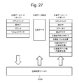
- FIG. 29 shows the compression information SGL.
- the ST processor 420 When the ST processor 420 secures a storage area for storing the target data in the ST memory 410, the ST processor 420 generates compressed information SGL indicating the storage area and stores it in the ST memory 410.
- the area for storing data in the ST memory 410 may be divided into a plurality of locations, and the compressed information SGL may have information for each of the plurality of addresses.
- the compression information SGL includes an identifier of the compression information SGL and information related to the compression information SGL, how many valid addresses are present in the compression information SGL, whether there is no next SGL, and is a terminal SGL. SGL information indicating that the next SGL address is valid is included.
- the compression information SGL further includes transfer data information (i) for each transfer data (i) in the target data (i is 0, 1,).
- the transfer data information (i) includes an address (i) of the compression information (i) in the ST memory 410 and a transfer size (i) indicating the compressed data size of the transfer data (i) corresponding to the address (i).
- the compression information SGL includes a next SGL address that is an address of the next compression information SGL when the next compression information SGL is set to be continuous in the SGL information described above.
- the compression information SGL includes an SGL field check code for checking each field in the compression information SGL. If there is compression for each compression unit and compression is not possible, the same number of blocks as the compression unit is stored. If compression is possible, the number of blocks smaller than the compression unit is stored and the compression presence flag is set.
- the transfer size may be omitted as it is calculated from the number of blocks after compression.
- the compression information SGL shown here is only an example, and other compression-related information such as the head offset position acquired by acquiring the compression information described above may be mounted.
- the SS connection mechanism 200 performs the compression. By tracing the information SGL, the target data can be read sequentially from the ST memory 410.
- the decompressed DMA request may include the contents of the compressed information SGL instead of the SGL address.
- the size of the decompressed DMA request may be enlarged or concatenated so that a large amount of information is loaded, and the content of the compressed information SGL may be placed in the decompressed DMA request without using the SGL.
- the compressed information may be mounted separately for both the decompressed DMA request and the SGL.
- the SV processor 120 when the SV processor 120 secures a storage area for storing the target data in the SV memory 110, the SV processor 120 generates a server SGL that is an SGL indicating the storage area, and stores the server SGL in the SV memory 110.
- the server SGL includes SGL information including an identifier of the server SGL, the number of valid addresses in the SGL, a flag indicating whether there is a next SGL, a flag indicating whether the SGL is a termination, and the server 100.
- Side storage destination address and transfer size A plurality of storage destination addresses and transfer sizes may be stored in the same manner as the compression information SGL. Further, a check code for the next SGL address or SGL field may be included. Further, information regarding other transfer destinations may be included.
- the SS connection mechanism 200 traces the server SGL, so that the SV memory 110 The target data can be read sequentially from
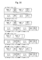
- FIG. 30 shows the data format
- the compressed data is stored in this format in the compressed storage device 600a.
- the compressed data is read from the compressed storage device 600a to the ST controller 400 in this format, and is read from the ST controller 400 to the SS connection mechanism 200.
- the SS connection mechanism 200 generates uncompressed data by decompressing the compressed data.
- the compressed data format includes a first compressed data format, a second compressed data format, and a third compressed data format
- the non-compressed data format includes a first uncompressed data format and a second uncompressed data format.
- the combination of the compressed data format and the non-compressed data format may be a combination other than the notation correspondence.
- the format shown here is an example, and other formats may be used as long as the correspondence between the compressed data format and the non-compressed data format is defined.
- the compressed data includes a plurality of compressed data blocks.
- the compressed data block is a compression unit. After each compressed data block, a security code for the compressed data block is added. When the compressed data block is expanded, it becomes a plurality of data blocks.
- a data block is a block. Each data block is followed by a security code for that data block.
- the storage device 600a When the compressed storage device 600a compresses and stores the data from the ST controller 400, the compressed data is distributed and written to a plurality of FMs 620. Therefore, the storage device indicates the CRC and the address in the FM 620 unique to the compressed storage device 600a.
- a dedicated code may be added. In this case, the second uncompressed data format is used. In the second non-compressed data format, a guarantee code of the data block is added after each data block, and a storage device dedicated code (dedicated code) is added after the guarantee code.
- the dedicated code shown here is a unique code added for exclusive use by the storage device 600 itself, and corresponds to, for example, a security code generated and added by the storage device 600.
- the storage device dedicated code is removed from the uncompressed data and transferred to the server 100. Further, as in the third non-compressed data format and the third non-compressed data format, the storage device dedicated code may be added to the compressed data. In this case as well, the SS connection mechanism 200 similarly uses the compressed data. Before decompressing, the storage device dedicated code is removed and the decompression process is performed.
- the server 100 reads the target data using the compressed data in the compressed storage device 600a as the target data
- the SS connection mechanism performs the decompression process in the DMA process, thereby enabling the data decompression process to be consistent with the direct data transfer process between the memories between the server storages.
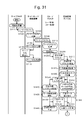
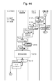
- FIG. 31 shows a first process in the SS system read process
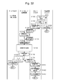
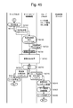
- FIG. 32 shows a second process following the first process in the SS system read process.
- These drawings show operations of the SV processor 120 in the server 100, the IF processor 210 in the SS connection mechanism 200, the ST processor 420 in the ST controller 400, and the SD processor 612 in the compressed storage device 600a.
- a read process when the target data expansion process is performed by the SS connection mechanism 200 will be described.
- the SV processor 120 in the server 100 prepares the SV memory 110 area for the read size in the SV memory 110 as a storage area for storing the read data.
- the SV processor 120 generates a server SGL, which is an SGL indicating the SV area, and stores it in the SV memory 110.
- the SV processor 120 generates a read request and issues it to the SS connection mechanism 200.
- the read request indicates a virtual volume indicating a storage area in which target data is stored and a virtual page in the virtual volume.
- the IF processor 210 in the SS connection mechanism 200 performs a read request process for analyzing a read request queued from the SV processor 120.
- IF processor 210 generates a read request based on the analysis result and issues it to ST controller 400.
- a read request from the IF processor 210 to the ST controller 400 may be referred to as a read command in order to distinguish from a read request from the SV processor 120 to the IF processor 210.
- the issue destination is the ST controller 400 and ST processor having ownership of the storage area for storing the specified target data.
- the IF processor 210 performs server SGL processing for acquiring the server SGL.
- the IF processor 210 receives the server SGL from the server 100.
- the IF processor 210 stores the received server SGL in the internal memory. Note that address information and length information to be mounted on the SGL may be included in the read request, and if the read request cannot be completed, the remaining information may be in the form of the SGL.
- the ST processor 420 in the ST controller 400 performs a read request process for analyzing the read request queued from the IF processor 210.
- the ST processor 420 executes a read request based on the virtual volume management table 810, the storage pool management table 820, the RAID group management table 830, the physical device management table 840, the virtual page management table 850, and the real page management table 860.
- the compressed storage device 600a storing the target data and the logical address of the storage area in the compressed storage device 600a are specified.
- the ST processor 420 determines whether or not to perform decompression DMA processing (compression determination).
- the ST processor 420 issues a compression information request for requesting compression information of the target data to the compression storage device 600a.
- the compression determination includes determination of whether the target data is stored in the cache in the ST controller 400. The cache determination will be described later.
- compression determination proceeds to S1420 (dotted arrow in the figure), a data storage area is secured with the size of uncompressed data, and both compressed information and compressed data are obtained only by a compressed data read request.
- the SD processor 612 of the compressed storage device 600a performs processing such as acquisition of compressed information (S1320 to S1360, within the dotted frame in the drawing) after receiving a compression read request (after S1430).
- the compressed storage device 600a may perform prefetching processing assuming a request for a compressed data read request.
- the SD processor 612 in the compression storage device 600a performs a compression information request process for analyzing the compression information request queued from the ST processor 420.
- the SD processor 612 acquires the compression information of the target data from the compression management table 920 in the RAM.
- the SD processor 612 calculates the overall size after compression, which is the size of the compressed data of the target data.
- the SD processor 612 issues a compression information response including the compression information of the target data to the ST processor 420.
- the SD processor 612 reads the compressed data of the target data from the FM 620, and stores the compressed data in the SD area that is a storage area in the RAM.
- the SD processor 612 rearranges the compressed data in the RAM based on the compression information.
- the ST processor 420 performs a compressed information response process for analyzing the compressed information response queued from the SD processor 612.
- the ST processor 420 secures an ST area, which is a storage area in the ST memory 410 for storing compressed data, in the ST memory 410 based on the compression information response (secure data storage area).
- the ST processor 420 issues a compressed data read request to the SD processor 612.
- the ST processor 420 generates compressed information SGL indicating the ST area and stores it in the ST memory 410.
- the SD processor 612 reads the compressed data from the RAM based on the compressed data read request queued from the ST processor 420, and shifts the processing to S1520 (A in the figure).
- the SD processor 612 transfers the read compressed data to the ST area of the ST controller 400 as the compressed data.
- the SD processor 612 issues a compressed data read response indicating the result of the compressed data read request to the ST processor 420.
- the SD processor 612 releases the SD area in the RAM and completes the read process. Note that the SD area in the RAM is released in response to an instruction from the ST processor 420 after the expanded DMA response is returned in consideration of retransmission. Alternatively, a timer may be set and released after a predetermined time has elapsed.
- the ST processor 420 determines that the decompression DMA is not performed in the compression determination S1220, the ST processor 420 performs normal read transfer, secures a data storage area with an uncompressed data size in S1420, and performs normal processing in S1430. Issue a read request. After that, the ST processor 420 performs a normal read transfer DMA request on the data read to the ST memory 410 in S1620. In this case, the compression information request S1230, the compression information request processing S1310, the post-compression total size calculation S1330, the compression information response S1340, and the compression information response processing S1410 are not performed.
- the compressed data read request S1430 is a normal read request that does not include an instruction to read the compressed data.
- the storage device 600 having received the compressed information acquisition S1320, reading compressed data from FM, DRAM storage S1350, and compressed data rearranging S1360 are executed in the storage device 600, and the expansion function (compression / decompression device 614) of the storage device 600 is executed. ),
- the normal read process is performed instead of the compressed read process S1510, the normal data is stored instead of the compressed data storage S1520, and the normal read response is returned to the ST processor 420 instead of the compressed read response S1530.
- the storage device 600 does not have a compression function and data compressed outside the storage device 600 is stored in the storage device 600 will be described. For example, this corresponds to a case where compressed data is stored in an HDD that is a storage device 600 that does not have a compression function.
- the storage system 300 grasps the presence / absence of the compression / decompression function for each storage device connected in advance. If it is not grasped, it can be set from the management apparatus of the storage system 300, or the ST processor 420 can access the storage device and confirm the presence / absence of the compression / decompression function.
- the ST processor 420 does not make a compression information request (S1320) to the storage device 600, and stores the data by reading the compression information from the storage area in which the ST processor 420 stores the compression information after the compression determination (S1220). The process proceeds to secure the area (S1420) (dotted line arrow in the figure). As the storage location of the compressed information, the ST memory 410, the flash memory mounted on the ST controller 400, the storage device 600, or the like can be considered. After obtaining the compression information, the ST processor 420 generates the compression information SGL (S1440), reads the compressed data to the ST controller 400 side (S1430 to S1610), and then sends an expanded DMA transfer request ( S1620) is issued.
- the ST processor 420 is mounted on the ST processor 420 or the ST controller 400 when the read data is compressed data after being read from the storage device 600 (S1430 to S1610). After decompressing the compressed data by using decompression hardware, the data is transferred by ordinary DMA transfer of uncompressed data instead of the decompression DMA request of S1620. If the read data is uncompressed data, the data is transferred by normal DMA transfer of uncompressed data instead of the decompression DMA request of S1620. When the read data is uncompressed data, when reading from the storage device 600 to the ST controller 400, the compressed data is decompressed in the storage device 600 and the data is compressed in the storage device 600. There may not be.
- the ST processor 420 uses the decompression DMA in the SS connection mechanism 200 as decompression hardware, and once reads the compressed data from the ST controller 400 to the SS connection mechanism 200, decompresses it, and writes it back to the ST controller 400. Later, a normal DMA request may be issued and transferred instead of the decompressed DMA request in S1620.
- the ST processor 420 generates SGL from the ST memory 410 area before the normal DMA request, reads uncompressed data to the ST controller 400 side, and then issues a DMA transfer request to the SS connection mechanism 200.
- the ST processor 420 performs a compressed data read response process for analyzing the compressed data read response queued from the SD processor 612.
- the ST processor 420 issues a decompressed DMA request to the IF processor 210.
- the SS connection mechanism 200 reads the data corresponding to the data size after compression from the ST controller 400, and It can be determined whether the decompression DMA transfer has been completed for the requested size.
- the IF processor 210 performs decompression DMA request processing for analyzing the decompression DMA request queued from the ST processor 420.
- the IF processor 210 acquires the compression information SGL in the ST memory 410 as necessary.
- the IF processor 210 activates the decompression DMA processing of the DMA controller 220.
- the DMA controller 220 performs decompression DMA processing based on an instruction from the IF processor 210, thereby reading and decompressing the compressed data stored in the ST area in the ST controller 400, and obtaining the obtained uncompressed data. Write to the SV area in the server 100.
- step S ⁇ b> 1750 the IF processor 210 receives a decompression DMA processing completion notification from the DMA controller 220.
- the IF processor 210 issues a read response to the SV processor 120 using an auto response when the normal transfer ends.
- the SV processor 120 completes the read process according to the read response queued from the IF processor 210.
- the IF processor 210 issues an expanded DMA response to the expanded DMA request to the ST processor 420.
- the ST processor 420 performs decompression DMA response processing for analyzing the decompression DMA response queued from the IF processor 210.
- the ST processor 420 releases the ST area.
- the ST processor 420 completes the read process.
- the ST controller 400 causes the SS connection mechanism 200 to decompress the compressed data, thereby reducing the bandwidth usage of the path from the compression storage device 600a to the SS connection mechanism 200, and the SS system.
- the IO performance can be improved.
- the ST processor 420 determines whether or not to perform the decompression DMA process when the read request is received from the IF processor 210 (S1220).
- the compression information management and decompression processing on the server 100 side become unnecessary.
- the compressed data can be shared between the servers 100 as a shared storage without transferring the compressed information between the plurality of servers 100. Note that by performing decompression DMA determination in conjunction with I / O on the storage side, decompression DMA transfer is performed based on information related to I / O characteristics such as I / O size and hit miss determination information of the ST memory 410.
- the ST processor 420 performs the decompression DMA process again according to the response of the storage device 600 when receiving the compressed data read response from the SD processor 612 (S1610). It may be determined whether or not.
- the SS connection mechanism 200 performs the decompression DMA process as shown in the read process described above.
- the SS connection mechanism 200 performs a normal DMA process for transferring the uncompressed data in the ST controller 400 to the server 100.
- the compressed storage device 600a may decompress the compressed data of the target data and transfer it to the ST controller 400, and the ST controller 400 may store uncompressed data, or the compressed storage device 600a may store the target data.
- the compressed data may be transferred to the ST controller 400, and the ST controller 400 may decompress and store the uncompressed data.
- R0 to R13 which are examples of conditions for compression determination (S1220) for determining that the ST processor 420 performs decompression DMA processing, will be described.
- a plurality of conditions R0 to R13 may be used simultaneously for compression determination.
- the ST processor 420 When the target data hits the cache in the ST controller 400 and the target cache hit data is compressed data, the ST processor 420 performs decompression DMA processing on the data. When the target cache hit data is uncompressed data, normal DMA processing is performed. When the target data has a cache miss, the ST processor 420 performs decompression DMA processing when the read request satisfies the following other conditions. As described above, the ST processor 420 makes a hit / miss determination, whereby exclusive control can be performed when there is a write request for the compressed data being transferred by the read request. For example, after the read transfer, the ST processor 420 deletes the compressed data on the cache area, expands the compressed data stored in the physical device, and writes the data. Thereby, it is possible to prevent a collision between a write and a read and to cope with a write process at the time of decompression DMA processing.
- the server 100 having the expansion function or the expansion function is provided.
- the ST processor 420 determines to perform decompression DMA processing.
- the external storage is a storage system 300 that is connected to the ST controller 400 and controlled by the ST controller 400.
- the compressed data stored in the storage device 600 is decompressed by the SS connection mechanism 200 and transferred to the server 100, whereby the bus in the storage system 300 and the bus between the storage system 300 and the SS connection mechanism 200 are transferred.
- the bandwidth can be widened, and the transfer time on those buses can be shortened.
- R2 Data compression / decompression is performed for each compression unit having a predetermined size. Therefore, for a read request having a data size equal to or smaller than the compression unit, extra data may be included to make the compression unit, and the amount read out may increase when viewed as uncompressed data. Therefore, this unnecessary data can be read and the load increases, which can be a factor that does not improve the system performance. Therefore, the ST processor 420 may determine not to perform decompression transfer when the data size at the time of non-compression specified by the read request is equal to or less than a specified value.
- the transfer process can be performed without waiting for the compressed information in the storage device 600 or the ST memory 410 to be read, so that the transfer process can be speeded up.
- the ST processor 420 stores the command history of the read request in the ST memory 410, and determines the sequentiality of the read request based on the command history. If the read request is determined to be sequential read and the storage area of the target data has the compression attribute of the condition R1, the decompression DMA process is determined.
- a bus between the storage device 600 and the ST controller 400, a bus in the ST controller 400, a bus between the ST controller 400 and the SS connection mechanism 200, and an SS connection mechanism The processing delay of the bus between 200 and the server 100 can be concealed, and the bandwidth of each transmission path can be used up.
- R4 If the compressed data of the target data is cached in the ST controller 400 and the ST processor 420 determines that the data is write data after the read request, it determines that there is sequentiality, and When the storage area of the target data has the compression attribute of the condition R1, the ST processor 420 performs decompression DMA processing. As a result, if the next data has been destaged to some extent in the cache area or buffer area, the ST processor 420 considers the possibility of using the data next, determines that it is a sequential read access, and is similar to the condition R3. For this reason, decompression DMA processing is performed.
- the ST processor 420 When the read request is an access to a storage area having the compression attribute of the condition R1 and the access frequency of the target data is low, the ST processor 420 holds the decompressed data because the necessity for the cache is low. It is determined that it is not necessary to carry out the extension DMA processing. As a result, the ST processor 420 determines that data with low access frequency may be deleted immediately without being destaged in the cache area of the ST controller 400, and performs decompression DMA processing. The target data of the decompression DMA processing is compressed, and when the cache hit occurs in the cache area of the ST controller 400, the overwrite cost is high. Therefore, the ST processor 420 uses the decompression DMA with the least frequently accessed and sequential data as much as possible. Since it is often desirable that data to be processed and frequently accessed is decompressed and stored in the cache area of the ST controller 400, the ST processor 420 normally performs DMA processing.
- the ST processor 420 When the ST controller 400 has a cache with a compression / decompression function and the target data is read via the cache, the ST processor 420 performs the decompression DMA process to compress the SS connection mechanism 200 while compressing it. Forward to. In this case, even if the compressed data is stored in the cache, the cache can expand the compressed data when there is a write to the compressed data, and therefore, the compressed data is transferred as it is.
- R7 When the uncompressed data of the target data hits the cache in the ST controller 400 and the cache is a cache with a compression / decompression function, the ST processor 420 determines that the decompression DMA transfer is performed, and the cache stores the target data. After compression, the band can be widened by transferring the compressed data by the decompression DMA processing of the SS connection mechanism 200.
- the ST processor 420 When the server 100 has a memory with a compression / decompression function and the transfer destination from the ST controller 400 is a memory with a compression / decompression function, the ST processor 420 performs normal DMA processing. If the decompression is performed with the memory with the compression / decompression function, the bus between the SS connection mechanism 200 and the memory with the compression / decompression function can be widened.
- the ST processor 420 performs the expansion DMA processing. To do.
- the transfer destination ST controller 400 has a compression / decompression function, it transfers the compressed data as it is. If the transfer destination ST controller 400 does not have a compression / decompression function, the transferred compressed data cannot be expanded.
- the ST processor 420 When the load of the compressed storage device 600a that stores the compressed data of the target data is high, the ST processor 420 offloads the expansion at the time of transfer to the expansion DMA processing. When there are a plurality of SS connection mechanisms 200, the ST processor 420 distributes the load of the decompression DMA processing based on the IO balance of the SS connection mechanism 200.
- the ST processor 420 determines the sequentiality of access to the target data based on the hint information from the server 100, the ST processor 420 performs decompression DMA processing.
- the hint information is information related to compression and decompression by the server 100 when the server 100 performs compression and decompression. This method is one of the methods for determining the sequentiality in order to obtain the same effect as the condition R1.
- FIG. 33 shows a first process in the decompression DMA process by the SS connection mechanism 200
- FIG. 34 shows a second process following the first process in the decompression DMA process by the SS connection mechanism 200.
- the DMA controller 220 of the SS connection mechanism 200 When the DMA controller 220 of the SS connection mechanism 200 receives the decompression DMA request from the ST controller 400, the DMA controller 220 executes decompression DMA processing.
- the DMA controller 220 analyzes the decompressed DMA request and specifies the addresses of the transfer source and the transfer destination.
- the transfer source address is acquired from the address (data address) set in the decompression DMA request or the compression information SGL.
- the transfer destination address when the SS connection mechanism 200 receives a read request from the server 100, the SS connection mechanism 200 holds the transfer request address in the read request in association with the identifier of the read request and manages the read request. Address information included in the server SGL or address information included in the server SGL is used.
- the DMA controller 220 acquires the compression information SGL as necessary, and acquires the compression information from the compression information SGL.
- the DMA controller 220 performs transfer while decompressing the compression unit group including the target data, and the size obtained by subtracting the head offset position from the decompressed data size becomes the transfer size specified by the decompression DMA request. Until all the transfers are completed, target compression units are selected in order from the target data of the decompression DMA processing, and S2130 to S2240 are repeated.
- the DMA controller 220 determines whether there is a guarantee code for the compressed data of the target compression unit. If it is determined that there is no guarantee code for the compressed data (S2140: N), the DMA controller 220 shifts the processing to S2160. If it is determined that there is a guarantee code for the compressed data (S2140: Y), in S2150, the DMA controller 220 performs a compressed data check process for checking the guarantee code for the compressed data, deletes the guarantee code, and the process proceeds to S2160. Transition.
- the DMA controller 220 determines whether or not the target compression unit is compressed. If it is determined that the target compression unit is not compressed (S2160: N), the DMA controller 220 shifts the process to S2180. If it is determined that the target compression unit is not compressed (S2160: N), the DMA controller 220 shifts the process to S2180. If it is determined that the target compression unit is compressed (S2160: Y), a dedicated code for the storage device is added to the compressed data, and if it is necessary to decompress after decompression, the dedicated code is removed. . In S2170, the DMA controller 220 generates uncompressed data from the compressed data of the target compression unit by performing the expansion processing of the target compression unit, and shifts the processing to S2180.
- the DMA controller 220 determines whether or not there is a security code for the decompressed uncompressed data generated by the decompression process. If it is determined that there is no guarantee code for uncompressed data (S2180: N), the DMA controller 220 shifts the process to S2210 (A in the figure). If it is determined that there is a security code for uncompressed data (S2180: Y), in S2190, the DMA controller 220 performs a non-compressed data check process for checking the security code for uncompressed data, deletes the security code, and performs processing. To S2210 (A in the figure).
- the DMA controller 220 determines whether or not the head offset position is set in the target compression unit, that is, whether or not data to be transferred is included. If it is determined that the target compression unit does not satisfy the data selection condition (S2210: N), the DMA controller 220 shifts the processing to S2230.
- the data selection condition is that the head offset position is set in the target compression unit and includes data that is not transferred.
- the DMA controller 220 determines the target compression unit in S2220.
- the transfer start position is moved from the head of the decompressed data by the head offset position, the data after the head offset position is transferred without transferring the data corresponding to the head offset position, and the process proceeds to S2230. Thereby, even when a part of the decompressed uncompressed data is the target data, the DMA controller 220 can transfer only the target data.
- the DMA controller 220 stores the data of the target compression unit in the transfer destination.
- the DMA controller 220 increases the address of the transfer start position of the target compression unit by the transferred size, and determines whether or not the transfer for the transfer size has been completed. If it is determined that the transfer has not been completed (S2240: N), the DMA controller 220 shifts the process to S2130 (B in the figure). If it is determined that the transfer has been completed (S2240: Y), in S2250, the DMA controller 220 notifies the ST controller 400 that the decompression DMA processing has been normally completed, and this flow is ended.
- the DMA controller 220 identifies the location where the error occurred. Therefore, the decompressed data is transferred through the same path and the location where the error occurs is specified.
- the SS connection mechanism 200 extracts the target data from the uncompressed data.
- the ST controller 400 extracts the target data from the uncompressed data. It may be extracted.
- the compressed data of the target data in the compression storage device 600a is transferred to the cache area of the FM with compression / decompression function or the cache area of the ST memory 410.
- the ST processor 420 decompresses the compressed data to generate uncompressed data using the flash hardware with compression / decompression function or the software of the ST processor 420, and extracts the target data from the uncompressed data.
- the ST processor 420 uses the flash hardware with compression / decompression function or the software of the ST processor 420 to compress the extracted target data, convert it into compressed data, and store it in the cache area. Thereby, it is possible to reduce the usage rate of the bus band between the cache area of the ST controller 400 and the SV memory 110 and improve the read performance.
- the above decompression DMA processing it is possible to transfer the compressed data from the ST controller 400 to the server 100 according to the situation by the determination on the storage system 300 side that grasps the I / O characteristics.
- Data decompression is realized by the DMA controller 220 and does not increase the load of the SV processor 120 on the server 100 side.
- the DMA controller 220 when the DMA controller 220 is installed on the server 100 side, it is possible to read data that exceeds the bandwidth between the ST controller and the server, thereby realizing effective use of the bandwidth.
- the utilization efficiency of the processor for analysis processing of the analysis server is reduced and the analysis processing time is reduced. It will increase.
- the read band can be widened, and the analysis process can be shortened by shortening the read time.
- the configuration of the present embodiment it is possible to check whether the compressed data and the non-compressed data are normal (decompression is successful). Even when the target data in the ST memory 410 is stored from the middle of a block that is a compression unit, only the target data can be transferred to the SV memory 110.
- FIG. 35 shows a first process in the security code check process during the decompression DMA process
- FIG. 36 shows a second process following the first process in the security code check process during the decompression DMA process.
- Reference numeral 37 denotes a third process following the second process in the security code check process during the decompression DMA process.
- the IF processor 210 of the SS connection mechanism 200 determines whether there is an error in the security code of the compressed data according to the compressed data check process. If it is determined that there is no error in the guarantee code of the compressed data (S2310: N), the IF processor 210 shifts the process to S2510. Note that even when no guarantee code is added to the compressed data, the flow is the same as when there is no error in the guarantee code of the compressed data.
- the IF processor 210 sets information indicating that an error has occurred in the compressed data guarantee code in the decompressed DMA response. In S2330, IF processor 210 issues an expanded DMA response to ST processor 420.
- the ST processor 420 determines whether or not the DMA controller 220 has failed. The determination of failure is made based on whether or not there is a notification from the DMA controller 220 that an internal error has occurred in the DMA controller 220. When there is a notification of a failure of the DMA controller 220 (S2340: Y), the ST processor 420 determines a DMA controller failure in S2350 and ends this flow. If the notification of the occurrence of an internal error is not issued even if the DMA controller 220 is faulty, the ST processor 420 cannot determine whether or not the DMA controller is faulty. The failure notification may be included as an internal error of the DMA controller 220 as an error in the decompressed DMA response.
- the ST processor 420 determines the preset error factor and the factor. In accordance with the defined processing, future operations such as blocking are determined, and this flow is terminated. In addition, it is good also as obstruction
- the IF processor 210 determines whether or not there is an error in the security code of the decompressed uncompressed data. If it is determined that there is no error in the security code of the uncompressed data (S2510: N), the IF processor 210 ends this flow.
- the IF processor 210 sets information indicating that an error has occurred in the non-compressed data guarantee code in the decompressed DMA response. .
- the IF processor 210 issues a decompressed DMA response to the ST processor 420.
- the ST processor 420 determines whether or not the DMA controller 220 has failed. Judgment is made in the same manner as the guarantee code of the compressed data described above. If there is a notification of a failure of the DMA controller 220 (S2550: Y), the ST processor 420 determines a DMA controller failure in S2550 and ends this flow.
- the ST processor 420 determines whether or not there is a guarantee code for the compressed data in S2560.
- the ST processor 420 checks the security code check result between the storage device 600 and the ST controller 400, and the security code check between the ST controller 400 and the SS connection mechanism 200. Since the locations where errors have occurred can be further narrowed down, future operations such as blockage are determined according to a predetermined error cause and processing defined for the cause according to the narrowed-down result, and this flow ends.
- the ST processor 420 shifts to the error check strengthening mode in S2610 (B in the figure).
- the ST processor 420 decides a future operation such as a blockage in accordance with a predetermined error factor and the process defined for the factor without shifting to the error check strengthening mode. The flow may be terminated.
- the ST processor 420 determines the possibility of an error in the storage device 600.
- the ST processor 420 secures an area that does not fit in the ST area out of the size of the uncompressed data of the target data, adds it to the ST area, and creates an SGL indicating the ST area.
- the ST processor 420 requests the compressed storage device 600a to decompress and transfer the compressed data of the target data stored in the compressed storage device 600a, and checks for errors on the transfer path. By transferring the decompressed data, it is possible to perform the same check as when the security code is attached to the compressed data with the decompressed data security code, and it is possible to isolate the location where the error occurred.
- the ST processor 420 identifies an error occurrence location. Here, the ST processor 420 shifts the process to the next even when the error occurrence location cannot be specified.
- the ST processor 420 determines a future operation such as blockage depending on the cause of the error, and ends this flow.
- the ST processor 420 determines a future operation such as blocking in accordance with a predetermined error factor and processing defined for the factor,
- the error check strengthening mode may be canceled until the threshold value is reached by ending this flow, or threshold management is performed, and retransmission may be performed by decompression DMA transfer, or transfer may be performed in error check strengthening mode.
- the ST processor 420 can identify an error occurrence location based on an error in the guarantee code of compressed data or non-compressed data, and can perform processing such as blocking the error occurrence location. . Further, the ST processor 420 can narrow down the error occurrence portion to some extent even when there is no guarantee code.
- the ST processor 420 may set a hit invalid flag in the cache area of the ST memory 410. In this case, the ST processor 420 can conceal the latency between the compressed storage device 600a and the cache area of the ST memory 410 by predicting and prefetching the next compressed data in sequential read.
- FIG. 38 shows the first process in the SS system write process
- FIG. 39 shows the second process following the first process in the SS system write process
- FIG. 40 shows the SS system write process.
- the 3rd process following the 2nd process in is shown.
- These drawings show the operations of the SV processor 120, the IF processor 210, the ST processor 420, and the SD processor 612.
- a write process when the target data compression process is performed by the SS connection mechanism 200 will be described.
- the SV processor 120 in the server 100 stores the target data for the write process in the SV area in the SV memory 110.
- the SV processor 120 generates a server SGL, which is an SGL indicating the SV area, and stores it in the SV memory 110.
- the SV processor 120 issues a write request for the target data to the SS connection mechanism 200.
- the IF processor 210 in the SS connection mechanism 200 performs a write request process for analyzing a write request queued from the SV processor 120.
- IF processor 210 generates a write request based on the analysis result and issues it to ST processor 420.
- a write request from the IF processor 210 to the ST controller 400 may be referred to as a write command in order to distinguish it from a write request from the SV processor 120 to the IF processor 210.
- the IF processor 210 performs server SGL processing for acquiring the server SGL.
- the IF processor 210 receives the server SGL from the server 100.
- the IF processor 210 stores the received server SGL in the internal memory.
- the information of the server SGL may be mounted on the write request, and the part not included in the write request may be put on the server SGL.
- the ST processor 420 in the ST controller 400 performs a write request process for analyzing the write request queued from the IF processor 210.
- the ST processor 420 determines whether or not to perform compression DMA processing (compression determination). If it is determined that the target data is compressed, in S3230, the ST processor 420 secures an ST area in the ST memory 410 for storing the compressed data of the target data based on the analysis result.
- the ST processor 420 generates compressed information SGL indicating the ST area and stores it in the ST memory 410.
- the ST processor 420 issues a compressed DMA request to the IF processor 210.
- the IF processor 210 performs a compressed DMA request process for analyzing the compressed DMA request.
- the IF processor 210 acquires the compression information SGL in the ST memory 410.
- the IF processor 210 activates the compression DMA processing of the DMA controller 220.
- the DMA controller 220 performs compression DMA processing based on an instruction from the IF processor 210, thereby reading and compressing the uncompressed data stored in the SV area in the server 100, and converting the obtained compressed data to ST Write to the ST area in the controller 400.
- the IF processor 210 receives a notification of the completion of the compressed DMA processing from the DMA controller 220 (shift to A in the figure).
- the IF processor 210 issues a compressed DMA response to the compressed DMA request to the ST processor 420.
- the ST processor 420 is notified of the data size before compression, the data size after compression, the compressed data size for each compression unit, and the presence / absence of compression, and is managed as compression information on the ST controller 400 side.
- the ST processor 420 performs a compressed DMA response process for analyzing the compressed DMA response queued from the IF processor 210.
- the ST processor 420 performs data redundancy that makes the compressed data in the ST area redundant.
- the ST processor 420 transfers the compressed data in the ST memory 410 to the ST memory 410 in another ST controller 400 via the inter-ST controller bus as data redundancy equivalent to RAID 1 that does not require parity calculation.
- the compressed data is stored in the ST memories 410 of the two ST controllers 400.
- the ST processor 420 may perform data redundancy that requires parity calculation, such as RAID5.
- the compressed data of the target data is transferred to the cache area in the ST controller 400.
- it is the cache area of the FM with compression / decompression function or the cache area of the ST memory 410.
- the ST processor 420 uses the compression / decompression function in the ST controller 400 to decompress the compressed data based on the compression information to generate uncompressed data.
- the compression / decompression function of the ST controller 400 is FM hardware with a compression / decompression function or software of the ST processor 420.
- the ST processor 420 performs RAID parity calculation and stores the generated parity in the cache area.
- the ST processor 420 uses the compression / decompression function of the ST controller 400 to compress the parity based on the compression information and store it in the cache area. Thereby, it is possible to reduce the usage rate of the bus band between the SV memory 110 and the cache area of the ST controller 400 and improve the write performance.
- the ST processor 420 issues a write response to the IF processor 210, and shifts the processing to S3510 (B in the figure).
- the IF processor 210 performs a write response process for analyzing the write response queued from the ST processor 420.
- the IF processor 210 issues a write response based on the analysis result to the SV processor 120.
- the SV processor 120 completes the write process.
- the ST processor 420 starts destage processing for writing the compressed data in the ST area to the compressed storage device 600a.
- the ST processor 420 issues a compression information write request including compression information about the compressed data to the SD processor 612 in the compression storage device 600a.
- the SD processor 612 writes the compressed information from the ST processor 420 to the RAM.
- the SD processor 612 issues a compressed information write response to the compressed information write request to the ST processor 420.
- the ST processor 420 issues a compressed data write request for writing compressed data to the SD processor 612.
- the SD processor 612 prepares an SD area for storing compressed data in the RAM based on the compressed data request.
- the SD processor 612 issues a compressed data write ready indicating the completion of preparation for writing compressed data to the ST processor 420.
- the ST processor 420 transmits the compressed data to the SD processor 612 according to the compressed data write ready queued from the SD processor 612.
- the SD processor 612 writes the compressed data to the SD area.
- the SD processor 612 issues a compressed data write response to the compressed data write request to the ST processor 420 in response to the completion of writing.
- the ST controller 400 causes the SS connection mechanism 200 to compress uncompressed data, thereby reducing the bandwidth usage of the path from the SS connection mechanism 200 to the compressed storage device 600a.
- the IO performance of the system can be improved.
- the ST processor 420 determines whether or not to perform the compressed DMA process at the time of receiving the write request for the target data from the IF processor 210 (S3220). Further, the ST processor 420 may determine whether or not to perform the compressed DMA process at the time when the compressed information SGL is generated (S3240). When it is determined that the compressed DMA process is to be performed, the SS connection mechanism 200 performs the compressed DMA process as shown in the write process described above. When it is determined not to perform the compressed DMA process, the SS connection mechanism 200 performs a normal DMA process for transferring the non-compressed data of the target data from the server 100 to the ST controller 400.
- the ST controller 400 may transfer the uncompressed data of the target data to the compressed storage device 600a, and the compressed storage device 600a may store the compressed data by compressing the uncompressed data. Data may be compressed, transferred to the compressed storage device 600a, and stored in the compressed storage device 600a.
- W1 to W13 which are examples of conditions for determining that the ST processor 420 performs the compressed DMA process, will be described.
- the ST processor 420 When the virtual page or pool attribute of the target data or the pool attribute or the virtual volume indicates the compression attribute, the management load increases unless the compressed data is managed together. Therefore, the ST processor 420 performs the compression DMA process. . In addition, since the compressed data has a variable length, it is necessary to manage the compressed data size and the capacity of the storage device 500. Therefore, the ST processor 420 designates the pool or volume storing the compressed data as the compressed data. It is easier to manage as a compressed volume for
- the ST processor 420 When it is determined that the write request satisfies the condition W1 and no parity operation is necessary when storing the disk in RAID 10 or the like, the ST processor 420 performs the compressed DMA process. When a parity operation is required, it is easier to manage after compressing the operation. For example, if a parity group is created from compressed data, the size changes each time overwriting is performed, so that all the compressed data in the parity group must be decompressed and the parity calculated again.
- the ST processor 420 stores the command history of the write request in the ST memory 410, and determines the sequential nature of the write request based on the command history. When it is determined that the write request is a sequential write and the write request satisfies the condition W1 or W2, the ST processor 420 performs a compressed DMA process. Similar to the above-described decompression DMA processing conditions W2 and W3, it is possible to use up the bandwidth of each transmission line by performing the compression DMA processing for sequential access.
- the ST processor 420 When it is determined that the write request satisfies the condition W1 or W2 and is directly transferred to the compressed storage device 600a without going through the cache in the ST controller 400, the ST processor 420 performs the compressed DMA processing. To do. This is because the ST processor 420 does not have to create a RAID parity or perform an overwrite process on the target data using a specialized path.
- the ST processor 420 When it is determined that the rewriting frequency of the target data is low or the target data is data for archive use, the ST processor 420 performs a compressed DMA process. Since it is not necessary to cache the target data, there is no need to decompress and overwrite the data on the cache. Therefore, by compressing and sending, the bandwidth of the bus can be widely used.
- FIG. 41 shows a first process in the compressed DMA process by the SS connection mechanism 200
- FIG. 42 shows a second process following the first process in the compressed DMA process by the SS connection mechanism 200.
- the DMA controller 220 of the SS connection mechanism 200 When the DMA controller 220 of the SS connection mechanism 200 receives the compressed DMA request from the ST controller 400, the DMA controller 220 executes the compressed DMA processing.
- the DMA controller 220 analyzes the compressed DMA request and specifies the transfer source and transfer destination addresses. In S4120, the DMA controller 220 selects a target block in order from the target data of the compressed DMA processing until the DMA processing of the transfer size obtained by subtracting the head offset position from the transfer block group size, and repeats S4120 to S4220.
- the DMA controller 220 determines whether to add a security code to the target block. Whether or not to be added is set from the ST controller 400 by a compressed DMA request. If it is determined that the guarantee code is not added to the target block (S4130: N), the DMA controller 220 shifts the process to S4150. If it is determined that a security code is to be added to the target block (S4130: Y), in S4140, the DMA controller 220 calculates a security code for the data before compression of the target block, adds the security code to the data, and performs processing in S4150. To move to.
- the DMA controller 220 In S4150, the DMA controller 220 generates compressed data by performing compression processing on the target block. In S4160, the DMA controller 220 determines whether or not to add a guarantee code to the compressed data. If it is determined that a security code is not added to the compressed data (S4160: N), the DMA controller 220 shifts the process to S4210 (A in the figure). If it is determined that a guarantee code is to be added to the compressed data (S4160: Y), in S4170, the DMA controller 220 calculates a guarantee code for the compressed data, adds the guarantee code to the compressed data, and performs the process in S4210 (in the figure). Move to A).
- the DMA controller 220 stores the compressed data of the target block in the transfer destination.
- the DMA controller 220 increases the address of the target block by the transferred size, and determines whether or not the transfer for the transfer size has been completed. When it is determined that the transfer has not been completed (S4220: N), the DMA controller 220 shifts the process to S4120 (B in the figure). If it is determined that the transfer has been completed (S4220: Y), in S4230, the DMA controller 220 notifies the ST controller 400 of the completion of the compressed DMA processing, and this flow is ended.
- uncompressed data can be transferred from the server 100 to the ST controller 400 while being compressed.
- a security code can be added to compressed data and non-compressed data.
- the SS connection mechanism 200 compresses the non-compressed data of the target data to generate compressed data, and when transferring the compressed data to the ST controller 400, either the uncompressed data or the compressed data is assigned a security code. Decide whether to add.
- the ST controller 400 may be preset to add a security code to both uncompressed data and compressed data, or based on storage area costs, communication costs, reliability of the storage device 600, and the like.
- the target to which the security code is added may be determined, or when the compressed storage device 600a does not transmit the read security code, it may be determined that the security code is added only to the uncompressed data.
- the compression storage device 600a when the compression storage device 600a is performing compression processing in the write processing, and the write request satisfies the condition W7, the compression processing in the write processing is offloaded from the compression storage device 600a to the SS connection mechanism 200.
- the compression offload write process will be described.
- FIG. 43 shows the compression offload write process.
- the process up to S3210 is performed in the same manner as the write process described above. If it is determined in S3220 that the write request satisfies the condition W7, in S3260, the ST processor 420 secures an ST area in the ST memory 410 for storing the compressed data of the target data based on the analysis result of the write request. . In S3270, the ST processor 420 generates compressed information SGL indicating the SV area that is the transfer source and the ST area that is the transfer destination, and stores the compressed information SGL in the ST memory 410. In S3280, the ST processor 420 selects the DMA controller 220 that performs the compressed DMA processing from among the SS connection mechanisms 200 connected to the transfer source (write request issuer) server 100 as a compressed DMA device.
- the ST processor 420 measures the I / O load of each DMA controller 220 and stores it in the ST memory 410, and selects the DMA controller 220 having the lowest I / O load as the compression DMA device. In S3290, the ST processor 420 issues a compressed DMA request to the compressed DMA device. Note that the information of the compression information SGL may be included in the write request, and the portion not included in the write request may be included in the compression information SGL.
- the subsequent processing is the same as S3310 to S3410 in the write processing described above.
- the decompression process in the read process is performed.
- the compression offload read process for offloading from the SS to the SS connection mechanism 200 will be described.
- the ST processor 420 performs decompression DMA processing from the SS connection mechanism 200 connected to the server 100 of the transfer destination (read request issue source) during the processing of read processing S1220 to S1620.
- the DMA controller 220 to be executed is selected as a decompression DMA device, and a decompression DMA request is issued to the decompression DMA device.
- the IO performance of the SS system can be improved.
- the server 100 includes an FM with a compression / decompression function.
- the SV processor 120 When the FM with compression / decompression function mounted on the server 100 compresses and decompresses the target data, the SV processor 120 provides hint information regarding compression and decompression by the server 100 in response to a write request and a read request to the SS connection mechanism 200. Is added.
- the ST processor 420 uses the hint information for determining whether or not to perform the compression DMA process and the decompression DMA process.
- the hint information indicates the compression / decompression algorithm.
- the ST processor 420 may perform compression DMA processing and decompression DMA processing based on the hint information.
- the ST processor 420 indicates the SS connection mechanism 200 based on the hint information by indicating the compression / decompression algorithm.
- the compression effect by the compression DMA processing and the decompression DMA processing may be performed when it is determined that the compression effect is determined.
- the ST controller 400 manages the data.
- the compression information is notified to the FM with compression / decompression function mounted on the server 100 via the SS connection mechanism 200.
- the FM with compression / decompression function installed in the server 100 compresses and decompresses the target data based on the compression information.
- the same subject in the reverse order of the compression process at the time of the write process and the encryption process or the deduplication process is the decompression process at the time of the read process and the decryption process that is the reverse conversion of the encryption process, or Reading is performed by performing restoration processing, which is inverse conversion of deduplication processing.
- the compressed storage device 600a compresses the data received from the ST controller 400 during the write process and then performs the encryption process or the deduplication process, the compressed storage device 600a performs the decryption process or the decompression during the read process. Processing is performed, and the compressed data is transmitted to the ST controller 400.
- the decoding process may be performed by the ST processor 420.
- the decoding process may be offloaded from the ST processor 420 to the FM with decoding function in the ST controller 400. Further, the data decompressed and processed in the ST controller 400 may be recompressed by the FM with a compression / decompression function.
- the management computer connected to the SS system via the communication network or the server 100 may set a policy for the ST controller 400 in advance.
- the ST processor 420 does not subject the data conforming to the policy to be subjected to the DMA decompression processing by the SS connection mechanism 200, and decompresses the data using the FM of the compression / decompression function installed in the ST controller 400 or the software of the ST processor 420. Ordinary DMA processing may be performed.
- the policy refers to, for example, data that is encrypted and compressed and stored in the storage device 600, or data that is deduplicated and compressed and stored in the storage device 600.
- the SS connection mechanism 200 in the write process may compress the deduplicated data and transfer it to the ST controller 400 in the same manner as the compression DMA process described above. Further, the SS connection mechanism 200 may expand the data from the ST controller 400 in the read process, similarly to the above-described expansion DMA process. In this case, after the data is transferred from the SS connection mechanism 200 to the SV memory 110, the SV processor 120 restores the deduplicated data to the original data.
- the compression storage device 600a may compress the deduplicated data in the write process.
- the compressed storage device 600a transfers the compressed data to the ST controller 400 as it is.
- the ST processor 420 decompresses the compressed data using an FM or the like with a compression / decompression function, restores the deduplicated data, compresses the restored data using an FM or the like with a compression / decompression function, and the compressed data
- the decompression DMA processing is performed on the.
- the compression storage device 600a or the ST controller 400 may compress the target data, and the ST processor 420 may perform deduplication of the compressed data.
- the ST processor 420 reads data from the storage device 600, cancels deduplication of the read data, and performs decompression DMA processing on the released data.
- the SS system may perform deduplication and deduplication cancellation instead of the compression and decompression described above. Also in this case, as in the case of compression and decompression, it is possible to reduce the bandwidth usage of the server-side bus, the bandwidth usage of the communication within the storage system, and the memory usage of the storage device.
- Compressed storage device 600a may perform compression and encryption.
- the compression storage device 600a compresses the target data and encrypts and stores the compressed data in order to reduce the storage capacity and protect the data.
- the compressed storage device 600a decrypts the stored data and transfers the decrypted data to the ST controller 400 (S1530).
- the compression rate deteriorates. Therefore, when the compression storage device 600a supports the compression function and the encryption function, it is desirable to compress the encrypted data before encryption.
- the data is transferred to the ST memory 410 while being compressed. Then, the SS connection mechanism 200 transfers the data to the server memory while expanding.
- the data may be transferred while being encrypted from the storage device 600 to the ST controller 400.
- the ST controller 400 reads the compressed and encrypted data from the compressed storage device 600a, decrypts the read data (S1610), and performs decompression DMA processing on the decrypted data.
- the ST controller 400 the ST processor 420 may perform decryption
- the ST controller 400 may include hardware dedicated to encryption / decryption
- the hardware may perform decryption
- the ST controller 400 has an encryption / decryption function.
- An FM may be included, and the FM may perform decoding.
- the data may be transferred from the storage device 600 to the server 100 while being encrypted. Decryption by the server 100 prevents data leakage and protects data from the data storage location in the storage system 300 and the data path in the storage system 300.
- the SV processor 120 decrypts the data transferred from the ST controller 400 to the SV memory 110 while being encrypted, and notifies the ST processor 420 of the completion of the decryption.
- the ST processor 420 instructs the SS connection mechanism 200 to perform a decompression DMA process between storage areas in the SV memory 110, so that the SS connection mechanism 200 decompresses the data in the SV memory 110.
- the SS connection mechanism 200 may have a decryption function.
- the compressed and encrypted data stored in the ST memory 410 is read by decompression DMA transfer, decrypted, and decompressed. Then, the data may be transferred to the SV memory 110.
- the server 100 includes a compression / decompression circuit for compression / decompression, and the server 100 is in charge of compression / decompression processing of target data, the SV processor 120 does not require compression / decompression by the SS connection mechanism 200 and the ST controller 400. An identifier indicating the presence is given to the read command and the write command. In this case, the ST processor 420 transmits information necessary for compression and decompression by the server 100 to the SV processor 120.
- the IO performance of the SS system can be improved and the security of the SS system can be improved.
- the decoding circuit may be an FM with a decoding function or an FM with a compression / decompression function having a decoding function.
- FIG. 44 shows a first process in the read process when the decryption by the server 100 and the decompression by the SS connection mechanism 200 are performed.
- FIG. 45 shows the read process when the decryption by the server 100 and the decompression by the SS connection mechanism 200 are performed. The 2nd process after the 1st process in a process is shown.
- the processing up to S1610 is performed in the same manner as the above-described read processing.
- ST memory 410 stores post-compression encrypted data that has been encrypted after compression, instead of compressed data.
- the ST processor 420 issues to the IF processor 210 a post-server transfer decompression DMA request that requests post-server transfer decompression DMA processing.
- the post-transfer decompression DMA processing includes normal DMA processing and post-transfer decompression DMA processing. In this normal DMA processing, the compressed data after compression of the target data is read from the ST memory 410 in the ST controller 400, and the compressed encrypted data is written in the SV memory 110 in the server 100.
- the post-transfer decompression DMA process reads the compressed data of the target data from the SV memory 110 in the server 100, decompresses the compressed data to generate uncompressed data, and stores the uncompressed data in the SV memory 110 in the server 100. Write.
- the IF processor 210 performs DMA request processing for analyzing the post-transfer decompression DMA request queued from the ST processor 420.
- the IF processor 210 acquires the compression information SGL in the ST memory 410.
- the IF processor 210 activates the normal DMA processing of the DMA controller 220.
- the DMA controller 220 performs normal DMA processing based on an instruction from the IF processor 210, thereby reading out the compressed encrypted data stored in the ST area in the ST controller 400, and the SV area in the server 100.
- the IF processor 210 receives a normal DMA processing completion notification from the DMA controller 220.
- the IF processor 210 issues a read response to the SV processor 120 using the auto response.
- the SV processor 120 shifts the processing to S6110 (B in the figure) according to the read response queued from the IF processor 210.
- the SV processor 120 performs decryption processing to decrypt the compressed data after compression using a decryption circuit, thereby converting the compressed data after compression into compressed data and transferring the compressed data to the SVR area in the SV memory 110. save.
- the SV processor 120 issues a post-transfer decompression DMA request for requesting post-transfer DMA processing to the IF processor 210.
- the IF processor 210 performs post-transfer decompression DMA request processing for analyzing the post-transfer decompression DMA request queued from the SV processor 120.
- the IF processor 210 acquires the compression information SGL in the ST memory 410.
- the IF processor 210 activates the decompression DMA processing of the DMA controller 220.
- the DMA controller 220 performs decompression DMA processing based on an instruction from the IF processor 210, thereby reading and decompressing the compressed data stored in the SVR area in the server 100, and converting the obtained uncompressed data to the server. Write to the SV area in 100.
- step S ⁇ b> 6750 the IF processor 210 receives a decompression DMA processing completion notification from the DMA controller 220.
- the IF processor 210 issues a post-transfer decompression DMA response to the SV processor 120 in response to the post-transfer decompression DMA request.
- the SV processor 120 completes the read process according to the read response queued from the IF processor 210.
- the IF processor 210 issues a post-server transfer decompression DMA response to the ST processor 420 in response to the post-server decompression DMA request.
- the ST processor 420 performs post-server transfer decompression DMA response processing for analyzing the post-server transfer decompression DMA response queued from the IF processor 210.
- the ST processor 420 releases the ST area.
- the ST processor 420 completes the read process.
- the above is the read processing when the server 100 performs decryption and the SS connection mechanism 200 performs decompression.
- data is encrypted in the path from the compressed storage device 600a to the SS connection mechanism 200 in the read process, and security can be improved. Further, the load can be distributed by the server 100 performing the decryption process and the SS connection mechanism 200 performing the decompression process. Note that the SS connection mechanism 200 may also perform the decoding process.
- the interface device (relay device, SS connection mechanism 200) connected to the server 100 and the storage system 300 is compressed from the ST controller 400.
- the interface device By reading the data, it is possible to reduce the amount of physical bandwidth used by the storage system 300.
- the interface device writes the compressed data to the ST controller 400, so that the physical bandwidth usage of the storage system 300 can be reduced. Thereby, the response time in the access from the server 100 to the storage system 300 can be reduced.
- the SS connection mechanism 200 connects the server 100 and the server 100 (server / server). May be used for data transfer.
- the transfer destination SS connection mechanism 200 is transferred.
- the decompression DMA transfer is performed in the same procedure as the decompression DMA transfer described above. As a result, the transfer between servers and servers can be widened, and can be performed at high speed, such as during inter-cluster transfer.
- the storage system 300a and the storage system 300a may be connected via the SS connection mechanism 200 (storage-storage connection) and used for data transfer.
- the compressed data stored in the storage device 300a of the storage system 300a or the ST memory 410 or the storage mounted flash memory 440 mounted in the ST controller 400a is used as the storage device 600 or ST memory 410 or storage mounted in the other storage system 300a.
- the extended DMA transfer is performed by the transfer destination SS connection mechanism 200 in the same procedure as the extended DMA transfer described above. Thereby, the transfer between the storage system 400a and the storage system 300a can be broadened, and the data read transfer from the external storage and the data read from the archive storage can be performed at high speed.
- the compressed DMA transfer may be performed in the method using the SS connection mechanism 200 for the server-server connection and the storage-storage connection described above.
- the SS connection mechanism 200 may be mounted on the I / F between the processor and the memory in the computer system, and the SS connection mechanism 200 may read the decompressed data stored in the memory in the same manner and expand it to the processor.
- the computer system may include an SS system or the like.
- the computer system may include a storage system 300 as a storage module.
- the computer system may include a server 100 or the like as a server module.
- the computer system may include an SS connection mechanism 200 and a relay device as interface devices.
- the computer system may include a compressed storage device 600a or the like as a storage device.
- the storage device may include an SD controller 610 or the like as a controller.
- the controller may include a compression / decompression device 614 or the like as an inverse conversion function.
- the storage device may include an FM 620 or the like as a memory.
- the computer system may include a compression device 221 or the like as a conversion function.
- the computer system may include a decompression device 222 or the like as an inverse conversion function.
- the computer system may include a compression / decompression device 614, an FM with a compression / decompression function, an ST processor 420, and the like as a conversion circuit.
- the computer system may use, for example, compression as conversion and expansion as inverse conversion.
- the computer system may use, for example, deduplication as conversion and deduplication restoration as inverse conversion.
- the computer system may use compressed data or the like as the target data after conversion.
- the computer system may use uncompressed data or the like as inverse transformation result data.
- the computer system may use an expanded DMA request or the like as an inverse conversion instruction.
- the computer system may use compressed information SGL or the like as the transfer source address.
- a decompression DMA request, compression information SGL, or the like may be used as a reply from the storage controller to the interface device.
- the computer system may use a compressed DMA request or the like as the conversion instruction.
- the computer system may use a normal DMA response or the like as a read instruction.
- the computer system may use an expanded DMA response or the like as a response indicating that the reverse conversion is successful.
- the computer system may use a non-compressed data guarantee code or the like as the first guarantee code, and may use non-compression guarantee code information or the like as the expected value of the first guarantee code.
- the computer system may use a compressed data guarantee code or the like as the second guarantee code, and may use compression guarantee code information or the like as the expected value of the second guarantee code.
- a server-side bus or the like may be used as a bus connecting the server processor and the interface device.
- a storage-side bus or the like may be used as a bus that connects the interface device and the storage processor.
Abstract
The present invention makes it possible to effectively reduce the amount of transfer data between server storages and implement an increase in the bandwidth of an effective band between server storages. When an interface device, which is located inside a server module, receives a read request issued by a server processor, the interface device transmits a read command based on the read request to a storage processor, and when an inverse transform instruction, which instructs the interface device to perform inverse transformation of transformed target data which is obtained by transforming target data in the read request, is received from the storage processor, the interface device performs DMA whereby transformed target data stored in a transfer source address in a storage memory is subjected to inverse transformation while being transferred to a transfer destination address in a server memory.
Description
本発明は、計算機システムおよび計算機システム制御方法に関する。
The present invention relates to a computer system and a computer system control method.
計算機システムで取り扱われるデータ量は近年ますます増加してきている。例えば、サーバからデータを日々収集してストレージ上でデータベースを構築し、所定のタイミングで、分析用サーバに蓄積したデータを読み出し、分析処理するような大規模データ分析システム技術が知られている。こうした計算機システムでは膨大な処理要求に対しての高速なレスポンスが求められる。
The amount of data handled by computer systems has been increasing in recent years. For example, a large-scale data analysis system technique is known in which data is collected from a server every day, a database is constructed on a storage, data stored in an analysis server is read and analyzed at a predetermined timing. Such a computer system is required to have a high-speed response to an enormous processing request.
一方で、サーバ及びストレージそれぞれの性能向上及び、フラッシュメモリ記憶装置のストレージ利用によるバックエンドの広帯域化に合わせて、サーバとストレージ間の接続帯域も、より広帯域化が必要となってきている。
On the other hand, as the performance of each server and storage is improved and the back-end bandwidth is increased by using the storage of the flash memory storage device, the connection bandwidth between the server and the storage needs to be wider.
例えば、サーバ計算機とストレージ装置がSAN(Storage Area Network)を介して接続される計算機システムにおいて、例えばサーバ計算機に圧縮伸張機構を設けることで圧縮されたデータをSANの線路を介して転送する技術が知られている(例えば、特許文献1)。
For example, in a computer system in which a server computer and a storage device are connected via a SAN (Storage Area Network), for example, there is a technique for transferring compressed data via a SAN line by providing a compression / decompression mechanism in the server computer, for example. Known (for example, Patent Document 1).
特許文献1のシステムは、サーバ計算機とストレージ装置間をFC(Fibre Channel)で接続している。本構成でサーバ計算機とストレージ装置間の帯域向上を図るには、FCのポート数増加や次世代品の利用などがあるが、高コストとなってしまう。
The system of Patent Document 1 connects a server computer and a storage device by FC (Fibre Channel). In order to improve the bandwidth between the server computer and the storage device with this configuration, there are an increase in the number of FC ports and the use of next-generation products, but the cost becomes high.
また、特許文献1のシステムはサーバ側にデータキャッシュ用のフラッシュメモリドライブを搭載し、リードデータのヒットミス判定を実施することでストレージアクセスの低減を可能とする。このため、フラッシュをサーバ側に準備し、サーバによるキャッシュ領域の管理が必要となる。更に、サーバ側での圧縮データを伸張せずに読み出すべきかについての判定を行うため、予めオブジェクト毎にポリシーを設定し、データが格納されている領域が圧縮されているかの情報をサーバ側で管理する必要がある。更に、キャッシュミスの場合にストレージデータをサーバ側メモリへの転送前に一旦フラッシュメモリに格納する処理、又、圧縮データの伸張処理等によるサーバ処理コストが大きく、結果としてパス帯域以外の伸張処理負荷が原因でシステム性能が低下する可能性がある。
In addition, the system of Patent Document 1 is equipped with a flash memory drive for data cache on the server side, and it is possible to reduce storage access by performing hit miss determination of read data. For this reason, it is necessary to prepare a flash on the server side and manage the cache area by the server. Further, in order to determine whether the compressed data on the server side should be read without being decompressed, a policy is set in advance for each object, and information on whether the data storage area is compressed is set on the server side. Need to manage. Furthermore, in the case of a cache miss, the storage data is temporarily stored in the flash memory before being transferred to the server-side memory, and the server processing cost due to the decompression processing of the compressed data is high, resulting in the decompression processing load other than the path bandwidth. Can cause system performance to degrade.
よって、本願ではアプリケーション側での事前設計を不要とし、I/Oの特性に連動して必要に応じた伸張リード、非伸張リードの使い分けを実現し、これにより、実効的にサーバストレージ間の転送データ量を削減し、サーバストレージ間の実効帯域の広帯域化を実現することを目的とする。
Therefore, this application eliminates the need for advance design on the application side, and implements separate use of decompressed and non-stretched leads according to the I / O characteristics, thereby effectively transferring data between server storages. The purpose is to reduce the amount of data and increase the effective bandwidth between server storages.
上記課題を解決するために、本発明の一態様である計算機システムは、ストレージプロセッサとストレージメモリと記憶デバイスとを有するストレージモジュールと、サーバプロセッサとサーバメモリとを有するサーバモジュールと、サーバプロセッサとストレージプロセッサとに接続されるインタフェースデバイスとを有する。インタフェースデバイスは、サーバモジュール内に位置し、サーバプロセッサにより発行されたリードリクエストを受信すると、リードリクエストに基づくリードコマンドを、ストレージプロセッサへ送信し、ストレージプロセッサから、リードリクエストの対象データを変換して得られた変換後対象データの逆変換をインタフェースデバイスに行わせるとの逆変換指示を受けた場合に、ストレージメモリ上の転送元アドレスに格納された変換後対象データを逆変換しながらサーバメモリ上の転送先アドレスに転送するDMA(Direct Memory Access)を行う。
In order to solve the above problems, a computer system according to one embodiment of the present invention includes a storage module including a storage processor, a storage memory, and a storage device, a server module including a server processor and a server memory, a server processor, and a storage. And an interface device connected to the processor. When the interface device is located in the server module and receives a read request issued by the server processor, the interface device transmits a read command based on the read request to the storage processor, and converts the target data of the read request from the storage processor. When receiving the reverse conversion instruction to cause the interface device to perform reverse conversion of the obtained target data after conversion, on the server memory while performing reverse conversion on the target data after conversion stored at the transfer source address on the storage memory DMA (Direct Memory Access) to transfer to the destination address.
以後の説明では「aaaテーブル」、「aaaリスト」、「aaaDB」、「aaaキュー」等の表現にて本発明の情報を説明するが、情報はテーブル、リスト、DB、キュー、等のデータ構造以外で表現されていてもよい。そのため、情報がデータ構造に依存しないことを示すために「aaaテーブル」、「aaaリスト」、「aaaDB」、「aaaキュー」等について「aaa情報」と呼ぶことがある。
In the following description, the information of the present invention will be described using expressions such as “aaa table”, “aaa list”, “aaaDB”, “aaa queue”, etc., but the information is a data structure such as a table, list, DB, queue, etc. It may be expressed in other than. Therefore, “aaa table”, “aaa list”, “aaaDB”, “aaa queue”, etc. may be referred to as “aaa information” to indicate that the information does not depend on the data structure.
更に、各情報の内容を説明する際に、「識別情報」、「識別子」、「名」、「名前」、「ID」という表現を用いるが、これらについてはお互いに置換が可能である。
Furthermore, in describing the contents of each information, the expressions “identification information”, “identifier”, “name”, “name”, and “ID” are used, but these can be replaced with each other.
以後の説明では「プログラム」を主語として説明を行う場合があるが、プログラムはプロセッサによって実行されることで定められた処理をメモリ及び通信ポート(通信制御デバイス)を用いながら行うため、プロセッサを主語とした説明としてもよい。また、プログラムを主語として開示された処理はストレージコントローラ等の計算機、情報処理装置が行う処理としてもよい。また、プログラムの一部又は全ては専用ハードウェアによって実現されてもよい。
In the following description, there is a case where “program” is used as the subject. However, since the program performs processing determined by being executed by the processor using the memory and communication port (communication control device), the processor is used as the subject. The explanation may be as follows. Further, the processing disclosed with the program as the subject may be processing performed by a computer such as a storage controller or an information processing apparatus. Further, part or all of the program may be realized by dedicated hardware.
また、各種プログラムはプログラム配布サーバや、計算機が読み取り可能な記憶メディア(computer-readable memory media)によって各計算機にインストールされてもよい。この場合、プログラム配布サーバはプロセッサ(例えばCPU:Central Processing Unit)と記憶資源を含み、記憶資源は更に配布プログラムと配布対象であるプログラムを記憶している。そして、配布プログラムをCPUが実行することで、プログラム配布サーバのCPUは配布対象のプログラムを他の計算機に配布する。
Further, various programs may be installed in each computer by a program distribution server or a computer-readable memory media. In this case, the program distribution server includes a processor (for example, CPU: Central Processing Unit) and a storage resource, and the storage resource further stores a distribution program and a program to be distributed. When the distribution program is executed by the CPU, the CPU of the program distribution server distributes the distribution target program to other computers.
以下、本発明の実施例について図面を用いて説明する。
Hereinafter, embodiments of the present invention will be described with reference to the drawings.
以下、本発明の実施例のサーバストレージ(SS)システムについて説明する。
Hereinafter, a server storage (SS) system according to an embodiment of the present invention will be described.
図1は、実施例のサーバストレージシステムの構成を示す。
FIG. 1 shows the configuration of the server storage system of the embodiment.
このSSシステムは、サーバ100と、ストレージシステム300とを含む。サーバ100とストレージシステム300は、一つの筺体に格納されていても良い。SSシステムを計算機システムと呼ぶことがある。
This SS system includes a server 100 and a storage system 300. The server 100 and the storage system 300 may be stored in one housing. The SS system is sometimes called a computer system.
サーバ100は、サーバ(SV)メモリ110と、サーバ(SV)プロセッサ120と、サーバストレージ(SS)接続機構200とを含む。SVメモリ110とSVプロセッサ120は、内部バスを介して互いに接続されている。SVメモリ110は、メモリであり、アプリケーション、OS(Operating System)、ドライバ等、サーバ100の制御のためのプログラム及びデータを格納する。SVプロセッサ120は、マイクロプロセッサであり、SVメモリ110内のプログラムに従って処理を実行する。SS接続機構200は、サーバ側バスを介してSVプロセッサ120に接続され、ストレージ側バスを介してストレージシステム300に接続され、SVプロセッサ120とストレージシステム300の間の通信を制御する。
The server 100 includes a server (SV) memory 110, a server (SV) processor 120, and a server storage (SS) connection mechanism 200. The SV memory 110 and the SV processor 120 are connected to each other via an internal bus. The SV memory 110 is a memory, and stores a program and data for controlling the server 100 such as an application, an OS (Operating System), and a driver. The SV processor 120 is a microprocessor and executes processing according to a program in the SV memory 110. The SS connection mechanism 200 is connected to the SV processor 120 via the server-side bus and is connected to the storage system 300 via the storage-side bus, and controls communication between the SV processor 120 and the storage system 300.
SVプロセッサ120とSS接続機構200の間は、サーバ側バスで接続されている。SS接続機構200とSTプロセッサ420の間は、サーバ側バスと同一形式のバスであるストレージ側バスで接続されている。本実施例は、サーバ側バス及びストレージ側バスとして、PCI Express(PCIe)を用いる。サーバ側バス及びストレージ側バスの夫々は、バックプレーン等の基板であっても良いし、ケーブルであっても良い。本システムでは、サーバ100の内部バスと同じバスでサーバ100からストレージシステム300までを接続することでサーバ100とストレージシステム300の記憶領域間のDMA転送を可能とし、SVプロセッサ120から発行した要求に対して、ストレージシステム300内のストレージ(ST)プロセッサがSS接続機構200に搭載したDMAエンジンを起動し、ストレージシステム300内のSTメモリ上のデータをSVメモリ110上へ、または、SVメモリ110上のデータをストレージシステム300内のSTメモリ上へ転送する。この構成により、サーバ100とストレージシステム300をいわゆるSAN等のネットワークスイッチのフォワード機能に頼らずに広帯域なバスで接続した一体型システムを構築し、帯域拡張とレイテンシ向上を実現する。さらに本システムにおいてDMA転送を実現することでI/O性能の向上を図ることができる。
The SV processor 120 and the SS connection mechanism 200 are connected by a server-side bus. The SS connection mechanism 200 and the ST processor 420 are connected by a storage-side bus that is the same type of bus as the server-side bus. In the present embodiment, PCI Express (PCIe) is used as the server-side bus and the storage-side bus. Each of the server side bus and the storage side bus may be a substrate such as a backplane or a cable. In this system, DMA transfer between the storage areas of the server 100 and the storage system 300 can be performed by connecting the server 100 to the storage system 300 through the same bus as the internal bus of the server 100, and the request issued from the SV processor 120 On the other hand, the storage (ST) processor in the storage system 300 activates the DMA engine installed in the SS connection mechanism 200, and the data on the ST memory in the storage system 300 is transferred to the SV memory 110 or the SV memory 110. Are transferred to the ST memory in the storage system 300. With this configuration, an integrated system in which the server 100 and the storage system 300 are connected by a broadband bus without depending on the forward function of a so-called SAN or other network switch is realized, and bandwidth expansion and latency improvement are realized. Furthermore, I / O performance can be improved by implementing DMA transfer in this system.
なお、サーバ100は、圧縮伸張機能を有するフラッシュメモリ(FM)である圧縮伸張機能付FMを含んでも良い。サーバ100は、内部バスを介してSVプロセッサ120に接続され且つサーバ側バスを介してSS接続機構200に接続されたRoot Complex(RC)を含んでも良い。
The server 100 may include an FM with a compression / decompression function, which is a flash memory (FM) having a compression / decompression function. The server 100 may include a Root Complex (RC) connected to the SV processor 120 via an internal bus and connected to the SS connection mechanism 200 via a server-side bus.
SS接続機構200は、サーバ100からのライトデータを圧縮してストレージシステム300へ転送し、ストレージシステム300からのリードデータを伸張してサーバ100へ転送する。
The SS connection mechanism 200 compresses the write data from the server 100 and transfers it to the storage system 300, decompresses the read data from the storage system 300 and transfers it to the server 100.
ストレージシステム300は、ストレージ(ST)コントローラ400と、記憶装置500とを含む。記憶装置500は、サーバ100からアクセスされるデータを格納する。STコントローラ400は、記憶装置500とサーバ100に接続され、記憶装置500へのアクセスを制御する。STコントローラ400をコントローラと呼ぶことがある。
The storage system 300 includes a storage (ST) controller 400 and a storage device 500. The storage device 500 stores data accessed from the server 100. The ST controller 400 is connected to the storage device 500 and the server 100 and controls access to the storage device 500. The ST controller 400 may be referred to as a controller.
STコントローラ400は、ストレージ(ST)メモリ410と、ストレージ(ST)プロセッサ420と、ドライブインタフェース(I/F)430とを含む。STメモリ410とSTプロセッサ420とドライブI/F430は、内部バスを介して互いに接続されている。STメモリ410は、メモリであり、ストレージシステム300の制御のためのプログラム及びデータを格納する。STプロセッサ420は、マイクロプロセッサであり、ストレージ側バスを介してSS接続機構200に接続され、STメモリ410に格納されたプログラムに従って処理を実行する。ドライブI/F430は、記憶装置側バスを介して記憶装置500に接続されており、STプロセッサ420と記憶装置500の間の通信を制御する。
The ST controller 400 includes a storage (ST) memory 410, a storage (ST) processor 420, and a drive interface (I / F) 430. The ST memory 410, the ST processor 420, and the drive I / F 430 are connected to each other via an internal bus. The ST memory 410 is a memory and stores a program and data for controlling the storage system 300. The ST processor 420 is a microprocessor, is connected to the SS connection mechanism 200 via a storage-side bus, and executes processing according to a program stored in the ST memory 410. The drive I / F 430 is connected to the storage device 500 via the storage device side bus and controls communication between the ST processor 420 and the storage device 500.
なお、STコントローラ400は、圧縮伸張機能付FMを含んでも良い。この場合、STプロセッサ420は、圧縮伸張機能付FMをキャッシュ領域として用い、キャッシュされたデータの圧縮及び伸張を行わせることができる。STコントローラ400は、内部バスを介してSTプロセッサ420に接続され且つストレージ側バスを介してSS接続機構200に接続されたRCを含んでも良い。
The ST controller 400 may include an FM with a compression / decompression function. In this case, the ST processor 420 can compress and expand the cached data using the FM with compression / decompression function as a cache area. The ST controller 400 may include an RC connected to the ST processor 420 via an internal bus and connected to the SS connection mechanism 200 via a storage-side bus.
記憶装置500は、複数の記憶デバイス600(#0、#1、#2、#3)を含む。物理的な記憶デバイス600を物理デバイスと呼び、仮想的な記憶デバイスを仮想デバイスと呼ぶことがある。データの圧縮伸張機能を含む物理デバイスを圧縮記憶デバイス600aと呼び、データの圧縮伸張機能を含まない物理デバイスを非圧縮記憶デバイス600bと呼ぶことがある。
The storage device 500 includes a plurality of storage devices 600 (# 0, # 1, # 2, # 3). The physical storage device 600 may be called a physical device, and the virtual storage device may be called a virtual device. A physical device including the data compression / decompression function may be referred to as a compressed storage device 600a, and a physical device not including the data compression / decompression function may be referred to as an uncompressed storage device 600b.
なお、データの圧縮及び復号は、圧縮記憶デバイス600aで行われても良いし、STコントローラ400により行われても良いし、サーバ100で行われても良い。
Note that the compression and decoding of data may be performed by the compression storage device 600a, the ST controller 400, or the server 100.
また、SSシステムにおける圧縮を、重複排除(deduplication)など、他の変換に置き換えることができる。この変換により元データから変換結果データが生成される。変換結果データのサイズは、元データのサイズより小さくなる。また逆変換により変換結果データから元データが生成される。圧縮に対する逆変換は、伸張である。重複排除に対する逆変換は元データの復元である。
Also, compression in the SS system can be replaced with other transformations such as deduplication. By this conversion, conversion result data is generated from the original data. The size of the conversion result data is smaller than the size of the original data. Further, original data is generated from the conversion result data by inverse conversion. The inverse transform for compression is decompression. The inverse transformation for deduplication is the restoration of the original data.
ここでは、サーバストレージシステムの構成の幾つかの具体例について説明する。
Here, some specific examples of the configuration of the server storage system will be described.
図2は、第一具体例のサーバストレージシステムの構成を示す。
FIG. 2 shows the configuration of the server storage system of the first specific example.
各SS接続機構200は、複数のSTコントローラ400に直接接続されていても良い。第一具体例のSSシステムは、複数のサーバ100と、一つのストレージシステム300を含む。ストレージシステム300は、二つのSTコントローラ400を含む。各STコントローラ400は、二つのSTプロセッサ420と、各STプロセッサ420に接続されている複数のSTメモリ410と、各STプロセッサ420に接続されている複数のドライブI/F430とを含む。一方のSTコントローラ400内の二つのSTプロセッサ420は、他方のSTコントローラ400内の二つのSTプロセッサ420にSTコントローラ400間バスを介して夫々接続されている。なお、STプロセッサ420は複数でもよい。複数の場合も夫々他方のSTコントローラ400内の複数のSTプロセッサ420にSTコントローラ間バスを介して夫々接続されている。
Each SS connection mechanism 200 may be directly connected to a plurality of ST controllers 400. The SS system of the first specific example includes a plurality of servers 100 and one storage system 300. The storage system 300 includes two ST controllers 400. Each ST controller 400 includes two ST processors 420, a plurality of ST memories 410 connected to each ST processor 420, and a plurality of drive I / Fs 430 connected to each ST processor 420. The two ST processors 420 in one ST controller 400 are respectively connected to the two ST processors 420 in the other ST controller 400 via the inter-ST controller 400 bus. A plurality of ST processors 420 may be provided. In the case of a plurality of ST controllers, each ST processor 420 in the other ST controller 400 is connected to each other via an inter-ST controller bus.
図3は、第二具体例のサーバストレージシステムの構成を示す。
FIG. 3 shows the configuration of the server storage system of the second specific example.
各SS接続機構200は、インタフェース拡張装置700を介して複数のSTコントローラ400に接続されていても良い。ここでは第一具体例に対する第二具体例の相違点について説明する。第二具体例のSSシステムは、複数のサーバ100と、各STコントローラ400とに接続されたインタフェース拡張装置700を含む。インタフェース拡張装置700は、サーバ100とSTコントローラ400の間の接続パス数を増やす制御を行う。インタフェース拡張装置700により、より多くのサーバ100が一台のストレージに直結できる。インタフェース拡張装置700は例えば、PCIeスイッチである。
Each SS connection mechanism 200 may be connected to a plurality of ST controllers 400 via the interface expansion device 700. Here, the difference between the second specific example and the first specific example will be described. The SS system of the second specific example includes a plurality of servers 100 and an interface expansion device 700 connected to each ST controller 400. The interface expansion device 700 performs control to increase the number of connection paths between the server 100 and the ST controller 400. With the interface expansion device 700, more servers 100 can be directly connected to one storage. The interface expansion device 700 is, for example, a PCIe switch.
図4は、第三具体例のサーバストレージシステムの構成を示す。
FIG. 4 shows the configuration of the server storage system of the third specific example.
各サーバ100は、複数のSS接続機構200を含んでいても良い。ここでは第二具体例に対する第三具体例の相違点について説明する。第三具体例において、各サーバ100は、二つのSS接続機構200を含む。二つのSS接続機構200は、インタフェース拡張装置700を介して二つのSTコントローラ400に夫々接続される。
Each server 100 may include a plurality of SS connection mechanisms 200. Here, the difference between the third specific example and the second specific example will be described. In the third specific example, each server 100 includes two SS connection mechanisms 200. The two SS connection mechanisms 200 are connected to the two ST controllers 400 via the interface expansion device 700, respectively.
この構成において、ストレージ側バスを2本のPCIex4、サーバ側バスを1本のPCIex8とすることにより、ストレージ側バスとサーバ側バスの帯域のバランスが取れるとする。ここで、ストレージ側バスを1本のPCIex4、サーバ側バスを1本のPCIex8に変更することにより、ストレージ側バスの帯域だけを1/2に変更する。この場合、ストレージ側バスからSS接続機構200へ転送された圧縮データがSS接続機構200で伸張されてサーバ側バスへ転送される際に、ストレージ側バスにおいて1/2に圧縮されていたデータが、サーバ側バスにおいてもとのサイズのデータに戻っても、ストレージ側バス及びサーバ側バスは、それぞれの帯域を確保できる。また、各サーバ100が2つのSS接続機構200を含むことでハードウェアの冗長性を確保できる。なお、各サーバ100が1つのSS接続機構200を含み、圧縮率を考慮してサーバ側バスの帯域をストレージ側バスより広帯域にしておいても良い。例えば、ストレージ側バスを2本のPCIex4とし、サーバ側バスを1本のPCIex16としても良い。更に、ストレージ側バスを2本のPCIex4とし、サーバ側バスを2本のPCIex8としても、同等の効果を得ることができる。このようにサーバ側バス及びストレージ側バスが、PCIeに従うことにより、圧縮に応じて必要な帯域を割り当てられることができる。
In this configuration, it is assumed that the storage side bus and the server side bus can be balanced by setting the storage side bus to two PCIex4 and the server side bus to one PCIex8. Here, by changing the storage side bus to one PCIex4 and the server side bus to one PCIex8, only the bandwidth of the storage side bus is changed to ½. In this case, when the compressed data transferred from the storage-side bus to the SS connection mechanism 200 is decompressed by the SS connection mechanism 200 and transferred to the server-side bus, the data that has been compressed to ½ in the storage-side bus is Even if the server-side bus returns to the original size data, the storage-side bus and the server-side bus can secure their respective bandwidths. Further, each server 100 includes two SS connection mechanisms 200, thereby ensuring hardware redundancy. Each server 100 may include one SS connection mechanism 200, and the bandwidth of the server side bus may be set wider than that of the storage side bus in consideration of the compression rate. For example, the storage side bus may be two PCIex4, and the server side bus may be one PCIex16. Furthermore, the same effect can be obtained even if the storage side bus is two PCIex4 and the server side bus is two PCIex8. In this way, the server-side bus and the storage-side bus can be assigned the necessary bandwidth according to the compression, according to PCIe.
図5は、第四具体例のサーバストレージシステムの構成を示す。
FIG. 5 shows the configuration of the server storage system of the fourth specific example.
SSシステムは、複数のストレージシステム300を含んでいても良い。ここでは第三具体例に対する第四具体例の相違点について説明する。第四具体例において、SSシステムは、二つのストレージシステム300を含む。一つのサーバ100内の二つのSS接続機構200は、インタフェース拡張装置700を介して二つのストレージシステム300に夫々接続される。一つのSS接続機構200は、インタフェース拡張装置700を介して一つのストレージシステム300内の二つのSTコントローラ400に接続される。この構成において、サーバ100に二つのSS接続機構200を搭載することで、より多くのストレージシステム300をサーバ100に接続することができ、サーバ100に対して広帯域、高性能なストレージリソースを提供できる。
The SS system may include a plurality of storage systems 300. Here, the difference between the fourth example and the third example will be described. In the fourth specific example, the SS system includes two storage systems 300. The two SS connection mechanisms 200 in one server 100 are connected to the two storage systems 300 via the interface expansion device 700, respectively. One SS connection mechanism 200 is connected to two ST controllers 400 in one storage system 300 via the interface expansion device 700. In this configuration, by installing two SS connection mechanisms 200 in the server 100, more storage systems 300 can be connected to the server 100, and broadband and high-performance storage resources can be provided to the server 100. .
図6は、仮想サーバストレージシステムの構成を示す。
FIG. 6 shows the configuration of the virtual server storage system.
物理的なSSシステム2000は、仮想化機構3000を実行し、仮想化機構3000上で仮想サーバストレージ(SS)システム1000を実行しても良い。仮想SSシステム1000は、仮想サーバ1100と、仮想ストレージシステム1300とを含む。この場合、SSシステム2000は少なくともプロセッサ2020、メモリ2010、記憶装置2500、SS接続機構2200を物理的に備える。仮想サーバ1100は、サーバ100と同様の機能を提供する。より具体的には、仮想サーバ1100は、SVメモリ110と同様の機能を提供する仮想SVメモリ2110と、SS接続機構200と同様の機能を提供する仮想SS接続機構1200とを含む。仮想ストレージシステム1300は、STコントローラ400と同様の機能を提供する仮想STコントローラ1400と、記憶装置500と同様の機能を提供する仮想記憶装置1500とを含む。仮想STコントローラ1400は、STメモリ410と同様の機能を提供する仮想STメモリ1410を含む。
The physical SS system 2000 may execute the virtualization mechanism 3000 and execute the virtual server storage (SS) system 1000 on the virtualization mechanism 3000. The virtual SS system 1000 includes a virtual server 1100 and a virtual storage system 1300. In this case, the SS system 2000 physically includes at least a processor 2020, a memory 2010, a storage device 2500, and an SS connection mechanism 2200. The virtual server 1100 provides the same function as the server 100. More specifically, the virtual server 1100 includes a virtual SV memory 2110 that provides the same function as the SV memory 110 and a virtual SS connection mechanism 1200 that provides the same function as the SS connection mechanism 200. The virtual storage system 1300 includes a virtual ST controller 1400 that provides the same functions as the ST controller 400 and a virtual storage device 1500 that provides the same functions as the storage device 500. The virtual ST controller 1400 includes a virtual ST memory 1410 that provides the same functions as the ST memory 410.
仮想化機構3000は、メモリ2010内の記憶領域を仮想SVメモリ1110に割り当て、SS接続機構2200の処理能力を仮想SS接続機構1200に割り当て、メモリ2010内の記憶領域を仮想STメモリ1410に割り当て、記憶装置2500内の記憶領域を仮想記憶装置1500に割り当てる。
The virtualization mechanism 3000 assigns the storage area in the memory 2010 to the virtual SV memory 1110, assigns the processing capacity of the SS connection mechanism 2200 to the virtual SS connection mechanism 1200, assigns the storage area in the memory 2010 to the virtual ST memory 1410, A storage area in the storage device 2500 is allocated to the virtual storage device 1500.
仮想SSシステム1000は、単独のサーバや、サーバとストレージシステム等、他の構成の計算機システム上で実行されても良い。また、計算機システムは、SS接続機構に代えて圧縮伸張回路を含んでも良い。
The virtual SS system 1000 may be executed on a computer system having another configuration such as a single server or a server and storage system. The computer system may include a compression / decompression circuit instead of the SS connection mechanism.
図7は、変形例のサーバストレージシステムの構成を示す。
FIG. 7 shows a configuration of a modified server storage system.
ここでは実施例のSSシステムに対する変形例のSSシステムの相違点について説明する。この変形例においてSSシステムは、ストレージシステム300の代わりにストレージシステム300aを有し、STコントローラ400の代わりにSTコントローラ400aを有する。サーバ100内のSS接続機構200に代えて、STコントローラ400a内にSS接続機構200が設けられる。SS接続機構200は、サーバ100内のSVプロセッサ120に接続され、STコントローラ400a内のSTプロセッサ420に接続される。サーバ100は更にFM140を含んでいても良い。このFM140が圧縮伸張機能を有し、SVプロセッサ120からの指示に応じて圧縮伸張を行っても良い。STコントローラ400aは更に、FM440を含んでいても良い。このFM440が圧縮伸張機能を有し、STプロセッサ420からの指示に応じて、SS接続機構200の代わりに圧縮又は伸張を行っても良い。本構成のとき、ライトの動作は図38~40に開示したフローにおいて、SS接続機構200への送出前にFM140でデータが圧縮される。SS接続機構200はこの圧縮データを読み出して伸張し、更に、本実施例のストレージシステム300の圧縮フォーマットに圧縮しなおしながらSTメモリ410を介して記憶デバイス600に書き込む。なお、SS接続機構200は圧縮データを読み出したときに伸張せずに、更に、本実施例のストレージシステム300の圧縮フォーマットに圧縮しても良い。本構成によりライト帯域を広帯域化することができる。又、リード動作は図31,32に開示したフローにおいてSTコントローラ400a内のFM440で圧縮されたデータまたは、記憶デバイス600に圧縮格納されたデータをSS接続機構200が読み出す場合に、データを伸張した上でサーバ100の圧縮フォーマットに圧縮しなおしながらサーバ100側のFM140またはSVメモリ110との間でDMA転送を行う。以上の構成により、SS接続機構200は、圧縮伸張機能を有したFM440と連携してシステムの広帯域化を実現する。なお、前述のようにSS接続機構200が伸張しないで圧縮データを読み出した場合、サーバ100の圧縮フォーマットに圧縮しなおさなくても良い。即ち、SS接続機構200は、サーバ100内に設けられても良いし、STコントローラ400内に設けられても良いし、サーバ100とSTコントローラ400の間に設けられても良い。
Here, differences between the SS system of the modification example and the SS system of the embodiment will be described. In this modification, the SS system includes a storage system 300a instead of the storage system 300, and includes an ST controller 400a instead of the ST controller 400. Instead of the SS connection mechanism 200 in the server 100, the SS connection mechanism 200 is provided in the ST controller 400a. The SS connection mechanism 200 is connected to the SV processor 120 in the server 100 and is connected to the ST processor 420 in the ST controller 400a. The server 100 may further include an FM 140. The FM 140 may have a compression / decompression function, and may perform compression / decompression in accordance with an instruction from the SV processor 120. The ST controller 400a may further include an FM 440. The FM 440 may have a compression / decompression function, and may perform compression or expansion instead of the SS connection mechanism 200 in response to an instruction from the ST processor 420. In this configuration, the write operation is performed by the FM 140 before the data is sent to the SS connection mechanism 200 in the flow disclosed in FIGS. The SS connection mechanism 200 reads out and decompresses this compressed data, and further writes it into the storage device 600 via the ST memory 410 while recompressing it into the compression format of the storage system 300 of this embodiment. Note that the SS connection mechanism 200 may further compress the compressed data into the compression format of the storage system 300 of this embodiment without expanding the compressed data when it is read. With this configuration, the write band can be widened. In addition, the read operation is performed when the SS connection mechanism 200 reads the data compressed by the FM 440 in the ST controller 400a or the data compressed and stored in the storage device 600 in the flow disclosed in FIGS. The DMA transfer is performed with the FM 140 or the SV memory 110 on the server 100 side while recompressing the compressed format of the server 100 above. With the above configuration, the SS connection mechanism 200 realizes a broadband system in cooperation with the FM 440 having a compression / decompression function. As described above, when the SS connection mechanism 200 reads the compressed data without decompressing, it is not necessary to recompress the data into the compression format of the server 100. That is, the SS connection mechanism 200 may be provided in the server 100, may be provided in the ST controller 400, or may be provided between the server 100 and the ST controller 400.
図8は、SS接続機構200の構成を示す。
FIG. 8 shows the configuration of the SS connection mechanism 200.
SS接続機構200は、例えば、ASIC(application specific integrated circuit)として実装される。SS接続機構200は、IF(Interface)プロセッサ210と、DMA(Direct Memory Access)コントローラ220と、内部メモリ230と、レジスタ240と、インタフェース250と、二つのインタフェース260と、内部スイッチ270とを含む。DMAコントローラ220をDMAと呼ぶことがある。IFプロセッサ210と、DMAコントローラ220と、内部メモリ230と、レジスタ240と、インタフェース250と、二つのインタフェース260とは、内部スイッチ270を介して互いに接続されている。一方のインタフェース250は、サーバ側バスを介してSVプロセッサ120に接続されている。他方の二つのインタフェース260は、ストレージ側バスを介して二つのSTプロセッサ420に夫々接続されている。内部メモリ230は、メモリであり、プログラム及びデータを格納する。IFプロセッサ210は、マイクロプロセッサであり、内部メモリ230内のプログラムに従って処理を実行する。DMAコントローラ220は、IFプロセッサ210からの指示に従ってデータ転送(メモリ間転送)を実行する。レジスタ240は、IFプロセッサ210の設定値を格納する。内部スイッチ270は、IFプロセッサ210からの指示に従って各部の間の通信を制御する。なお、SV側インタフェース及びST側インタフェースは夫々複数あって、各バス及びインタフェース拡張を介して、SVプロセッサ120とSTプロセッサ420に接続されていても良い。
The SS connection mechanism 200 is implemented as, for example, an ASIC (application specific integrated circuit). The SS connection mechanism 200 includes an IF (Interface) processor 210, a DMA (Direct Memory Access) controller 220, an internal memory 230, a register 240, an interface 250, two interfaces 260, and an internal switch 270. The DMA controller 220 may be called DMA. The IF processor 210, the DMA controller 220, the internal memory 230, the register 240, the interface 250, and the two interfaces 260 are connected to each other via an internal switch 270. One interface 250 is connected to the SV processor 120 via a server-side bus. The other two interfaces 260 are connected to the two ST processors 420 via storage-side buses, respectively. The internal memory 230 is a memory and stores programs and data. The IF processor 210 is a microprocessor and executes processing according to a program in the internal memory 230. The DMA controller 220 executes data transfer (transfer between memories) according to an instruction from the IF processor 210. The register 240 stores a setting value of the IF processor 210. The internal switch 270 controls communication between the units in accordance with instructions from the IF processor 210. Note that there may be a plurality of SV side interfaces and ST side interfaces, and they may be connected to the SV processor 120 and the ST processor 420 via each bus and interface expansion.
図9は、DMAコントローラ220の構成を示す。
FIG. 9 shows the configuration of the DMA controller 220.
DMAコントローラ220は、圧縮デバイス221と、伸張デバイス222と、保障コード処理デバイス(0)224と、保障コード処理デバイス(1)224と、データ転送制御デバイス225と、二つのインタフェース226、227とを含む。二つのインタフェースは、内部スイッチに接続されている。圧縮デバイス221は、非圧縮データを圧縮して圧縮データに変換する。伸張デバイス222は、圧縮データを伸張して非圧縮データに変換する。保障コード処理デバイス(0)223は、非圧縮データの保障コードを算出し、非圧縮データに保障コードを付加する。更に、保障コード処理デバイス(0)223は、非圧縮データと保障コードに基づいて非圧縮データの誤りを検出する。保障コード処理デバイス(1)は、圧縮データの保障コードを算出し、圧縮データに保障コードを付加する。更に、保障コード処理デバイス(1)224は、圧縮データと保障コードに基づいて圧縮データの誤りを検出する。また、夫々の保障コード処理デバイスは、保障コードの削除も行う。データ転送制御デバイス225は、データの転送を制御する。
The DMA controller 220 includes a compression device 221, an expansion device 222, a guarantee code processing device (0) 224, a guarantee code processing device (1) 224, a data transfer control device 225, and two interfaces 226 and 227. Including. The two interfaces are connected to an internal switch. The compression device 221 compresses uncompressed data and converts it into compressed data. The decompression device 222 decompresses the compressed data and converts it into uncompressed data. The guarantee code processing device (0) 223 calculates a guarantee code for uncompressed data, and adds a guarantee code to the uncompressed data. Further, the guarantee code processing device (0) 223 detects an error in the non-compressed data based on the non-compressed data and the guarantee code. The guarantee code processing device (1) calculates a guarantee code for the compressed data and adds the guarantee code to the compressed data. Furthermore, the guarantee code processing device (1) 224 detects an error in the compressed data based on the compressed data and the guarantee code. Each security code processing device also deletes the security code. The data transfer control device 225 controls data transfer.
SS接続機構200がサーバ100とSTコントローラ400にPCIeで接続されることにより、サーバ100内のSVメモリ110と、STコントローラ400のSTメモリ410の間でDMA転送を行うことができ、DMA転送時にデータの圧縮又は伸張を行うことができる。
By connecting the SS connection mechanism 200 to the server 100 and the ST controller 400 via PCIe, DMA transfer can be performed between the SV memory 110 in the server 100 and the ST memory 410 of the ST controller 400. Data compression or decompression can be performed.
以下、圧縮記憶デバイス600aについて説明する。
Hereinafter, the compressed storage device 600a will be described.
図10は、圧縮記憶デバイス600aの構成を示す。
FIG. 10 shows the configuration of the compressed storage device 600a.
圧縮記憶デバイス600aは、記憶デバイス(SD)コントローラ610と、SDコントローラ610に接続されている複数のフラッシュメモリ(FM)620とを含む。SDコントローラ610は、RAM(Random Access Memory)611と、物理デバイス(SD)プロセッサ612と、保障コード処理デバイス613と、圧縮・伸張デバイス614と、I/Oインタフェース615と、FMインタフェース616とを含む。SDコントローラ610内の各部は内部バスを介して互いに接続されている。I/Oインタフェース615は、記憶装置側バスを介してSTコントローラ400のドライブI/F430に接続されている。RAM611は、例えばDRAM(Dynamic RAM)であり、プログラム及びデータを格納する。SDプロセッサ612は、マイクロプロセッサであり、RAM611に格納されたプログラムに従って処理を実行する。保障コード処理デバイス613は、データに基づいて保障コードを生成し、データに保障コードを付加し、データと保障コードに基づいてデータのチェックをし、誤りを検出する。また、保障コードの削除も行う。圧縮・伸張デバイス614は、非圧縮データを圧縮して圧縮データに変換し、圧縮データを伸張して非圧縮データに変換する。FMインタフェース616は、複数のFM620に接続されている。この圧縮記憶デバイス600aが、STプロセッサ420からの指示に応じて、SS接続機構200の代わりに圧縮又は伸張を行っても良い。また、圧縮記憶デバイス600aは、データ入力に対して内部判断でデータを圧縮しても良く、STプロセッサ420から特に指示がない場合は内部で圧縮されているデータを伸張して出力しても良い。
The compressed storage device 600 a includes a storage device (SD) controller 610 and a plurality of flash memories (FM) 620 connected to the SD controller 610. The SD controller 610 includes a RAM (Random Access Memory) 611, a physical device (SD) processor 612, a guarantee code processing device 613, a compression / decompression device 614, an I / O interface 615, and an FM interface 616. . Each unit in the SD controller 610 is connected to each other via an internal bus. The I / O interface 615 is connected to the drive I / F 430 of the ST controller 400 via the storage device side bus. The RAM 611 is a DRAM (Dynamic RAM), for example, and stores programs and data. The SD processor 612 is a microprocessor and executes processing according to a program stored in the RAM 611. The security code processing device 613 generates a security code based on the data, adds a security code to the data, checks the data based on the data and the security code, and detects an error. The security code is also deleted. The compression / decompression device 614 compresses the uncompressed data and converts it into compressed data, and decompresses the compressed data and converts it into uncompressed data. The FM interface 616 is connected to a plurality of FMs 620. The compressed storage device 600a may perform compression or expansion in place of the SS connection mechanism 200 in response to an instruction from the ST processor 420. Further, the compression storage device 600a may compress the data by internal determination with respect to the data input, and may decompress and output the internally compressed data unless there is a specific instruction from the ST processor 420. .
以下、ストレージシステム300内の記憶領域の構成について説明する。
Hereinafter, the configuration of the storage area in the storage system 300 will be described.
図11は、STメモリ410内の記憶領域の構成を示す。
FIG. 11 shows the configuration of the storage area in the ST memory 410.
STメモリ410内の記憶領域は、仮想ボリューム管理テーブル810と、ストレージプール管理テーブル820と、RAIDグループ管理テーブル830と、物理デバイス管理テーブル840と、仮想ページ管理テーブル850と、実ページ管理テーブル860と、空き実ページ管理テーブル870とを含む。これらのテーブルについては後述する。STメモリ410内の記憶領域は更に、ストレージ(ST)キャッシュ領域880と、ストレージ(ST)バッファ領域890とを含む。STキャッシュ領域880は、ライトデータやリードデータを一時的に保持し、ライトやリードアクセスに対する、データヒットに利用する。STバッファ領域890は、STコントローラ400により送受信されるデータや制御情報を格納する。
The storage area in the ST memory 410 includes a virtual volume management table 810, a storage pool management table 820, a RAID group management table 830, a physical device management table 840, a virtual page management table 850, and a real page management table 860. And a free real page management table 870. These tables will be described later. The storage area in the ST memory 410 further includes a storage (ST) cache area 880 and a storage (ST) buffer area 890. The ST cache area 880 temporarily holds write data and read data, and is used for data hits for write and read access. The ST buffer area 890 stores data and control information transmitted / received by the ST controller 400.
図12は、圧縮記憶デバイス600a内の記憶領域の構成を示す。
FIG. 12 shows the configuration of the storage area in the compressed storage device 600a.
圧縮記憶デバイス600a内の記憶領域は、RAMにおける、メタデータ領域910と、キャッシュ領域930と、バッファ領域940と、FM620における、データ領域950とを含む。メタデータ領域910は、メタデータを格納し、圧縮管理テーブル920を含む。キャッシュ領域930は、一時的なデータを格納する。バッファ領域940は、圧縮記憶デバイス600aにより送受信されるデータや制御情報を格納する。データ領域950は、データを格納する。なお、SDコントローラ610内のRAM611内の情報は接続されているFM620内にあっても良い。
The storage area in the compressed storage device 600a includes a metadata area 910, a cache area 930, a buffer area 940, and a data area 950 in the FM 620 in the RAM. The metadata area 910 stores metadata and includes a compression management table 920. The cache area 930 stores temporary data. The buffer area 940 stores data and control information transmitted / received by the compressed storage device 600a. The data area 950 stores data. Note that the information in the RAM 611 in the SD controller 610 may be in the connected FM 620.
図13は、ストレージシステム300内の記憶領域の構成を示す。
FIG. 13 shows the configuration of the storage area in the storage system 300.
STコントローラ400は、物理デバイス内の記憶領域を仮想デバイスに割り当てる。物理デバイスは、圧縮記憶デバイス600a(圧縮SD)と非圧縮記憶デバイス(非圧縮SD)の何れであっても良い。STコントローラ400は、複数の仮想デバイスを用いてパリティグループを作成する。パリティグループは、複数の圧縮記憶デバイス600aに夫々基づく複数の仮想デバイスを用いる圧縮パリティグループと、複数の非圧縮記憶デバイスに夫々基づく複数の仮想デバイスを用いる非圧縮パリティグループとの何れであっても良い。STコントローラ400は、ストレージプール管理テーブル820を用いて、パリティグループ内の記憶領域をストレージプールに割り当てる。STコントローラ400は、仮想ボリューム管理テーブル810を用いて、ストレージプール内の記憶領域を仮想ボリュームに割り当てる。ストレージプール毎に、圧縮データ格納用の圧縮ストレージプールと、圧縮されずに格納されるデータ用の非圧縮ストレージプールが存在してもよい。尚、圧縮ストレージプールは、例えば圧縮機能を有した機能デバイスの記憶領域で構成された圧縮パリティグループによって提供されていてもよいし、当該プールへの格納はSTコントローラ400やSTコントローラ400に接続される圧縮機構によって圧縮されるような構成としてもよい。また、仮想ボリュームも書き込まれたデータが圧縮されて記憶領域に格納される圧縮仮想ボリュームと書き込まれたデータが圧縮されることなく記憶領域に格納される非圧縮仮想ボリュームがあっても良く、混在していても良い。STコントローラ400は、仮想ボリュームをサーバ100へ提供する。
The ST controller 400 allocates a storage area in the physical device to the virtual device. The physical device may be either a compressed storage device 600a (compressed SD) or an uncompressed storage device (uncompressed SD). The ST controller 400 creates a parity group using a plurality of virtual devices. The parity group may be either a compressed parity group using a plurality of virtual devices based on a plurality of compressed storage devices 600a or an uncompressed parity group using a plurality of virtual devices respectively based on a plurality of uncompressed storage devices. good. The ST controller 400 uses the storage pool management table 820 to allocate storage areas in the parity group to the storage pool. The ST controller 400 uses the virtual volume management table 810 to allocate a storage area in the storage pool to the virtual volume. For each storage pool, there may be a compressed storage pool for storing compressed data and an uncompressed storage pool for data stored without being compressed. The compressed storage pool may be provided by, for example, a compressed parity group including a storage area of a functional device having a compression function, and storage in the pool is connected to the ST controller 400 or the ST controller 400. It may be configured to be compressed by a compression mechanism. The virtual volume can also be a compressed virtual volume in which written data is compressed and stored in the storage area, and an uncompressed virtual volume in which the written data is stored in the storage area without being compressed. You may do it. The ST controller 400 provides the virtual volume to the server 100.
図14は、ストレージシステム300内のページの構成を示す。
FIG. 14 shows the configuration of pages in the storage system 300.
パリティグループは、複数の実ページを含む。仮想ボリュームは、複数の仮想ページを含む。STコントローラ400は、実ページ管理テーブル860を用いて、実ページを仮想ページに割り当てる。圧縮パリティグループを用いることにより、仮想ページに割り当てる実ページの合計サイズを物理デバイスの合計サイズより大きくすることができる。また、STコントローラ400は、圧縮パリティグループ内の実ページと非圧縮パリティグループ内の実ページとを切り替えて仮想ページに割り当てることができる。これにより、圧縮の効果の有無を切り替えることができる。また、圧縮パリティグループを用いるときに、仮想ページに割り当てる実ページの合計サイズを物理デバイスの合計サイズと同じサイズにして、FM620の容量を増やさないで利用率を下げ、FM620を長寿命化することもできる。
Parity group includes multiple real pages. The virtual volume includes a plurality of virtual pages. The ST controller 400 uses the real page management table 860 to assign real pages to virtual pages. By using the compressed parity group, the total size of real pages allocated to virtual pages can be made larger than the total size of physical devices. Also, the ST controller 400 can switch between a real page in the compressed parity group and a real page in the non-compressed parity group and assign it to the virtual page. Thereby, the presence or absence of the compression effect can be switched. In addition, when using a compressed parity group, the total size of real pages allocated to virtual pages is set to the same size as the total size of physical devices, the utilization rate is reduced without increasing the capacity of the FM 620, and the life of the FM 620 is extended. You can also.
図15は、仮想ボリューム管理テーブル810を示す。
FIG. 15 shows the virtual volume management table 810.
仮想ボリューム管理テーブル810は、仮想ボリューム毎のエントリを含む。一つの仮想ボリュームに対応するエントリは、ボリューム番号(#)と、ボリューム容量と、割当済み容量と、プール番号(#)と、ボリューム属性とを含む。ボリューム番号は、当該仮想ボリュームを示す識別子である。ボリューム容量は、当該仮想ボリュームの容量である。割当済み容量は、当該仮想ボリューム内で、実ページが割り当てられている仮想ページの合計サイズである。プール番号は、当該仮想ボリュームに割り当てることができる実ページを含むストレージプールを示す識別子である。ボリューム属性は、当該仮想ボリュームにおける圧縮の有無を示す。
The virtual volume management table 810 includes an entry for each virtual volume. An entry corresponding to one virtual volume includes a volume number (#), a volume capacity, an allocated capacity, a pool number (#), and a volume attribute. The volume number is an identifier indicating the virtual volume. The volume capacity is the capacity of the virtual volume. The allocated capacity is the total size of virtual pages to which real pages are allocated in the virtual volume. The pool number is an identifier indicating a storage pool including a real page that can be allocated to the virtual volume. The volume attribute indicates the presence or absence of compression in the virtual volume.
図16は、ストレージプール管理テーブル820を示す。
FIG. 16 shows the storage pool management table 820.
ストレージプール管理テーブル820は、ストレージプール毎のエントリを含む。一つのストレージプールに対応するエントリは、プール番号(#)と、RAID(Redundant Arrays of Inexpensive Disks)グループリストと、プール属性と、空き仮想ページ数とを含む。プール番号は、当該ストレージプールを示す識別子である。RAIDグループリストは、当該ストレージプールに含まれるRAIDグループを示す識別子である。プール属性は、当該ストレージプールに用いられている物理デバイスの種類を示す。空き仮想ページ数は、当該ストレージプールの空き仮想ページの数を示す。尚、システム内に図13に示したように圧縮ストレージプールと非圧縮ストレージプールを設ける場合には、圧縮/非圧縮のプール属性を格納する欄があってもよい。
The storage pool management table 820 includes an entry for each storage pool. The entry corresponding to one storage pool includes a pool number (#), a RAID (Redundant Arrays of Inexpensive Disks) group list, a pool attribute, and the number of free virtual pages. The pool number is an identifier indicating the storage pool. The RAID group list is an identifier indicating a RAID group included in the storage pool. The pool attribute indicates the type of physical device used for the storage pool. The number of free virtual pages indicates the number of free virtual pages in the storage pool. When a compressed storage pool and an uncompressed storage pool are provided in the system as shown in FIG. 13, there may be a column for storing a compressed / uncompressed pool attribute.
図17は、RAIDグループ管理テーブル830を示す。
FIG. 17 shows the RAID group management table 830.
RAIDグループ管理テーブル830は、RAIDグループ毎のエントリを含む。一つのRAIDグループに対応するエントリは、RAIDグループ番号(#)と、RAIDレベルと、物理デバイス番号(#)とを含む。RAIDグループ番号は、当該RAIDグループを示す識別子である。RAIDレベルは、当該RAIDグループのRAIDレベルを示す。物理デバイス番号は、当該RAIDグループに用いられている物理デバイスを示す識別子である。
The RAID group management table 830 includes an entry for each RAID group. An entry corresponding to one RAID group includes a RAID group number (#), a RAID level, and a physical device number (#). The RAID group number is an identifier indicating the RAID group. The RAID level indicates the RAID level of the RAID group. The physical device number is an identifier indicating a physical device used for the RAID group.
図18は、物理デバイス管理テーブル840を示す。
FIG. 18 shows the physical device management table 840.
物理デバイス管理テーブル840は、物理デバイス毎のエントリを含む。一つの物理デバイスに対応するエントリは、仮想デバイス番号(#)と、物理デバイス番号(#)と、物理容量と、論理使用容量と、物理使用容量とを含む。仮想デバイス番号は、当該物理デバイスを割り当てられた仮想デバイスを示す識別子である。物理デバイス番号は、当該物理デバイスを示す識別子である。物理容量は、当該物理デバイスの容量である。論理使用容量は、当該仮想デバイスの論理記憶領域の使用量である。物理使用容量は、当該物理デバイスの物理記憶容量の使用量である。
The physical device management table 840 includes an entry for each physical device. The entry corresponding to one physical device includes a virtual device number (#), a physical device number (#), a physical capacity, a logical usage capacity, and a physical usage capacity. The virtual device number is an identifier indicating a virtual device to which the physical device is assigned. The physical device number is an identifier indicating the physical device. The physical capacity is the capacity of the physical device. The logical usage capacity is the usage amount of the logical storage area of the virtual device. The physical usage capacity is the usage amount of the physical storage capacity of the physical device.
図19は、仮想ページ管理テーブル850を示す。
FIG. 19 shows a virtual page management table 850.
仮想ページ管理テーブル850は、仮想ページ毎に作成される。一つの仮想ページに対応する仮想ページ管理テーブル850は、仮想ボリューム番号(#)と、実ページポインタと、ページ属性とを含む。仮想ボリューム番号は、当該仮想ページを含む仮想ボリュームを示す識別子である。実ページポインタは、当該仮想ページに割り当てられた実ページを指すポインタである。ページ属性は、当該実ページが圧縮データを格納するか非圧縮データを格納するかを示す。この図に示されている二つの仮想ページ管理テーブル850のうち、上の仮想ページ管理テーブル850は、実ページを割り当てられている仮想ページを示し、実ページポインタが実ページを指している。下の仮想ページ管理テーブル850は、実ページを割り当てられていない仮想ページを示し、実ページポインタがNULLを示している。
The virtual page management table 850 is created for each virtual page. The virtual page management table 850 corresponding to one virtual page includes a virtual volume number (#), a real page pointer, and a page attribute. The virtual volume number is an identifier indicating a virtual volume including the virtual page. The real page pointer is a pointer that points to a real page assigned to the virtual page. The page attribute indicates whether the actual page stores compressed data or non-compressed data. Of the two virtual page management tables 850 shown in this figure, the upper virtual page management table 850 indicates a virtual page to which a real page is allocated, and a real page pointer points to the real page. The lower virtual page management table 850 indicates a virtual page to which no real page is allocated, and the real page pointer indicates NULL.
図20は、実ページ管理テーブル860を示す。
FIG. 20 shows the real page management table 860.
実ページ管理テーブル860は、実ページ毎に作成される。一つの実ページに対応する実ページ管理テーブル860は、RAIDグループ番号(#)と、実ページ先頭アドレスと、空きページポインタとを含む。RAIDグループ番号は、当該実ページを含むRAIDグループを示す識別子である。実ページ先頭アドレスは、当該RAIDグループにおける当該実ページの先頭アドレスを示す。空きページポインタは、当該実ページが空き実ページである場合に次の空き実ページの実ページ管理テーブル860を指す。
The real page management table 860 is created for each real page. The real page management table 860 corresponding to one real page includes a RAID group number (#), a real page head address, and a free page pointer. The RAID group number is an identifier indicating a RAID group including the real page. The real page head address indicates the head address of the real page in the RAID group. The free page pointer points to the real page management table 860 of the next free real page when the real page is a free real page.
図21は、空き実ページ管理テーブル870を示す。
FIG. 21 shows a free real page management table 870.
空き実ページ管理テーブル870は、空きページ管理ポインタを含む。この空きページ管理ポインタは、空きページの実ページ管理テーブル860を指す。連続する空きページの最後の空きページの実ページ管理テーブル860内の空きページポインタは、空きページ管理ポインタを指す。
The free real page management table 870 includes a free page management pointer. This empty page management pointer points to the actual page management table 860 for empty pages. The empty page pointer in the real page management table 860 of the last empty page of consecutive empty pages indicates the empty page management pointer.
図22は、物理デバイス内の記憶領域の構成を示す。
FIG. 22 shows the configuration of the storage area in the physical device.
圧縮記憶デバイス600aは、圧縮管理テーブル920をRAM611またはFM620に格納する。圧縮記憶デバイス600aのSDコントローラ610は、記憶領域のブロック単位の論理アドレスをSTコントローラ400へ提供し、圧縮管理テーブル920を用いて論理アドレスに対しブロック単位で実アドレスを割り当てる。ここで示すブロック単位はブロックストレージのデータ単位を示す。圧縮記憶デバイス600aは、非圧縮データ換算で複数ブロックをまとめた単位(例えばブロックサイズ0.5kBを複数個まとめた8kB、以降圧縮単位)で圧縮可否を判断し、圧縮する場合にはこの単位で非圧縮データを圧縮単位毎に圧縮する。非圧縮記憶デバイスは、実アドレス管理テーブルをRAMに格納する。非圧縮記憶デバイスのSDコントローラ610は、ブロック毎の論理アドレスをSTコントローラ400へ提供し、実アドレス管理テーブルを用いて論理アドレスに対しブロックの実アドレスを割り当てる。
The compression storage device 600a stores the compression management table 920 in the RAM 611 or the FM 620. The SD controller 610 of the compressed storage device 600a provides the ST controller 400 with a logical address in units of blocks in the storage area, and assigns real addresses in units of blocks to the logical addresses using the compression management table 920. The block unit shown here indicates a data unit of block storage. The compression storage device 600a determines whether or not compression is possible in a unit in which a plurality of blocks are grouped in terms of non-compressed data (for example, 8 kB in which a plurality of block sizes of 0.5 kB are grouped, hereinafter compression unit). Compress uncompressed data for each compression unit. The uncompressed storage device stores the real address management table in the RAM. The SD controller 610 of the uncompressed storage device provides a logical address for each block to the ST controller 400, and assigns a real address of the block to the logical address using the real address management table.
図23は、圧縮管理テーブル920を示す。
FIG. 23 shows the compression management table 920.
圧縮管理テーブル920は、記憶デバイス600毎に、記憶デバイス600内のRAM611またはFM620に格納される。記憶デバイス600がHDDの場合、圧縮管理テーブル920はHDDに格納される。別の方法として複数の記憶デバイス600の圧縮管理テーブル920をまとめて、ストレージコントローラのSTメモリ410、または、ストレージコントローラのフラッシュメモリに格納して管理しても良い。
The compression management table 920 is stored in the RAM 611 or FM 620 in the storage device 600 for each storage device 600. When the storage device 600 is an HDD, the compression management table 920 is stored in the HDD. As another method, the compression management tables 920 of a plurality of storage devices 600 may be collected and stored in the ST memory 410 of the storage controller or the flash memory of the storage controller for management.
圧縮管理テーブル920は、圧縮記憶デバイス600a内の圧縮単位毎のエントリを含む。一つの圧縮単位に対応するエントリは、論理アドレスと、実アドレスと、圧縮フラグと、圧縮後ブロック数とを含む。論理アドレスは、当該圧縮データの先頭の論理アドレスを示す。実アドレスは、当該圧縮単位の先頭の実アドレスを示す。圧縮フラグは、当該圧縮単位のデータが圧縮されるか否かを示す。圧縮後ブロック数は、当該非圧縮データの圧縮後のデータについてのブロック数を示す。ここで、圧縮単位内のブロックがすべて非圧縮データだった場合の圧縮後ブロック数を最大ブロック数とし、圧縮単位が圧縮ブロックを含む場合、圧縮ブロック数は最大ブロック数より小さい。即ち、圧縮単位内のブロックがすべて非圧縮ブロックである場合、圧縮後ブロック数は一定であり、圧縮単位が圧縮ブロックを含む場合、圧縮後ブロック数は可変である。なお、圧縮後ブロック数が最大ブロック数と同じまたは多い場合、非圧縮データを圧縮データの代わりに格納するため、圧縮後ブロック数が最大ブロック数と同じである場合、非圧縮データが格納されることとし、当該圧縮単位のデータが圧縮されているか否かを示す圧縮フラグはなくても良い。図23では8KBの圧縮単位が8KBの圧縮データとなっている場合を示しており、このときは圧縮フラグで該当の8KBが圧縮データか否かを判別するようにしている。
The compression management table 920 includes an entry for each compression unit in the compression storage device 600a. An entry corresponding to one compression unit includes a logical address, a real address, a compression flag, and the number of blocks after compression. The logical address indicates the first logical address of the compressed data. The real address indicates the first real address of the compression unit. The compression flag indicates whether data in the compression unit is compressed. The number of blocks after compression indicates the number of blocks for the compressed data of the uncompressed data. Here, when all the blocks in the compression unit are non-compressed data, the number of blocks after compression is the maximum block number. When the compression unit includes a compression block, the number of compression blocks is smaller than the maximum block number. That is, when all the blocks in the compression unit are non-compression blocks, the number of blocks after compression is constant, and when the compression unit includes compression blocks, the number of blocks after compression is variable. When the number of blocks after compression is the same as or larger than the maximum number of blocks, uncompressed data is stored instead of compressed data. Therefore, when the number of blocks after compression is the same as the maximum number of blocks, uncompressed data is stored. In other words, there may be no compression flag indicating whether or not the data of the compression unit is compressed. FIG. 23 shows a case where the 8 KB compression unit is 8 KB compressed data. At this time, it is determined by the compression flag whether the corresponding 8 KB is compressed data.
図24は、STコントローラ400が圧縮記憶デバイス600aから圧縮情報を取得する第一の動作を示す。
FIG. 24 shows a first operation in which the ST controller 400 acquires compressed information from the compressed storage device 600a.
圧縮情報は、圧縮記憶デバイス600aに格納されている対象データの圧縮に関する情報である。STコントローラ400は、対象データの圧縮情報を取得するための圧縮情報リクエストを圧縮記憶デバイス600aへ発行する。圧縮記憶デバイス600aは、圧縮情報リクエストに応じて対象データの圧縮情報を圧縮管理テーブル920から読み出し、圧縮情報を示す圧縮情報レスポンスをSTコントローラ400へ発行する。圧縮情報は、対象データの圧縮の状態を示す。圧縮情報リクエストは、圧縮情報を要求することを示すコマンドコードと、当該リクエストの識別子と、圧縮記憶デバイス600a内での対象データの論理アドレスであるアドレスと、対象データのサイズであるリクエストサイズとを含む。圧縮情報レスポンスは、対応する圧縮情報リクエストの識別子と、対象データを含む圧縮単位群の圧縮後のサイズである圧縮後全体サイズと、当該対象データを含む圧縮単位群の先頭の圧縮単位を伸張した際に、その伸張データの先頭から対象データの先頭までのオフセットである先頭オフセット位置とを含む。更に圧縮情報レスポンスは、当該圧縮単位群内の圧縮単位毎に、当該圧縮単位の圧縮の有無を示す圧縮有無フラグと、圧縮後の当該圧縮単位内のブロック数を示す圧縮後ブロック数とを含む。なお、STコントローラ400が、圧縮後ブロック数が圧縮前ブロック数と同じ場合は非圧縮と判定し、圧縮後ブロック数と圧縮前ブロック数が異なる場合は圧縮と判定する場合、圧縮有無フラグを不要としても良い。
Compression information is information related to compression of target data stored in the compression storage device 600a. The ST controller 400 issues a compression information request for acquiring the compression information of the target data to the compression storage device 600a. The compression storage device 600a reads the compression information of the target data from the compression management table 920 in response to the compression information request, and issues a compression information response indicating the compression information to the ST controller 400. The compression information indicates the compression state of the target data. The compression information request includes a command code indicating that the compression information is requested, an identifier of the request, an address that is a logical address of the target data in the compression storage device 600a, and a request size that is the size of the target data. Including. The compressed information response is obtained by decompressing the corresponding compressed information request identifier, the compressed overall size of the compressed unit group including the target data, and the first compressed unit of the compressed unit group including the target data. The first offset position, which is an offset from the beginning of the decompressed data to the beginning of the target data. Further, the compression information response includes, for each compression unit in the compression unit group, a compression presence / absence flag indicating the presence / absence of compression of the compression unit, and a post-compression block number indicating the number of blocks in the compression unit after compression. . When the ST controller 400 determines that the number of blocks after compression is the same as the number of blocks before compression, the ST controller 400 determines non-compression, and when the number of blocks after compression differs from the number of blocks before compression, the compression presence / absence flag is unnecessary It is also good.
この動作によれば、STコントローラ400は、圧縮記憶デバイス600aやSS接続機構200等、STコントローラ400以外により圧縮されたデータの圧縮情報を取得することができる。また、STコントローラ400が、SSシステム内の他の部位へ圧縮情報を送ることにより、圧縮を行った部位以外の部位であっても、伸張に必要な圧縮情報を取得することができる。また、STコントローラ400は、複数の圧縮記憶デバイス600aに分散されて格納されている圧縮データを論理アドレス順に夫々読み出すと共に、夫々の圧縮記憶デバイス600aから圧縮情報を取得することにより、複数の圧縮記憶デバイス600aに分散された格納されている圧縮データを連続してSTメモリ410へ保存するように並びかえることができる。なお、STコントローラ400は、並び替えにはSGLをつかい、論理的に連続させ、物理的に連続していなくても良い。これにより、SS接続機構200は、STメモリ410から圧縮データをシーケンシャルに読み出すことができる。
According to this operation, the ST controller 400 can acquire compression information of data compressed by other than the ST controller 400, such as the compression storage device 600a and the SS connection mechanism 200. In addition, the ST controller 400 can obtain the compression information necessary for decompression by sending the compression information to other parts in the SS system even if the part is a part other than the part where the compression is performed. Further, the ST controller 400 reads the compressed data distributed and stored in the plurality of compressed storage devices 600a in the order of logical addresses, and acquires the compression information from the respective compressed storage devices 600a, whereby a plurality of compressed storages are obtained. The compressed data stored in the device 600a can be rearranged so as to be continuously stored in the ST memory 410. Note that the ST controller 400 uses SGL for rearrangement and is logically continuous, and may not be physically continuous. As a result, the SS connection mechanism 200 can sequentially read the compressed data from the ST memory 410.
図25は、STコントローラ400が圧縮記憶デバイス600aから圧縮データを取得する動作を示す。
FIG. 25 shows an operation in which the ST controller 400 acquires compressed data from the compressed storage device 600a.
圧縮記憶デバイス600aは、STコントローラ400から受信したデータを圧縮して格納した場合、通常のリードリクエストに応じて、圧縮データを伸張して非圧縮データを生成し、非圧縮データをSTコントローラ400へ送信することができる。
When the compressed storage device 600a compresses and stores the data received from the ST controller 400, the compressed storage device 600a generates uncompressed data by expanding the compressed data in response to a normal read request, and sends the uncompressed data to the ST controller 400. Can be sent.
ここでは、STコントローラ400は、圧縮記憶デバイス600aに格納されている対象データを圧縮データのままで取得するための、圧縮データリードリクエストを圧縮記憶デバイス600aへ発行する場合について説明する。圧縮記憶デバイス600aは、圧縮データリードリクエストに応じて圧縮データを読み出し、対象データの圧縮データを送信し、その読み出しの結果を示す圧縮データリードレスポンスをSTコントローラ400へ発行する。圧縮データリードリクエストは、圧縮データの圧縮したままのリードを指示するコマンドコードと、当該リクエストの識別子と、圧縮記憶デバイス600a内での対象データの論理アドレスであるアドレスと、対象データのサイズであるリクエストサイズとを含む。なお、対象データのサイズは前述の圧縮情報リードで取得した値を利用する。圧縮データリードレスポンスは、対応する圧縮データリードリクエストの識別子と、リードの処理に関するステータスと、STコントローラ400へ転送される対象データのサイズを示す転送サイズとを含む。
Here, a case will be described in which the ST controller 400 issues a compressed data read request to the compressed storage device 600a in order to acquire target data stored in the compressed storage device 600a as compressed data. The compressed storage device 600a reads the compressed data in response to the compressed data read request, transmits the compressed data of the target data, and issues a compressed data read response indicating the read result to the ST controller 400. The compressed data read request is a command code for instructing to read compressed data as it is compressed, an identifier of the request, an address that is a logical address of the target data in the compressed storage device 600a, and a size of the target data. Including request size. Note that the value acquired by the above-described compression information read is used as the size of the target data. The compressed data read response includes an identifier of the corresponding compressed data read request, a status related to the read processing, and a transfer size indicating the size of the target data transferred to the ST controller 400.
この動作によれば、STコントローラ400は、対象データの圧縮データを、圧縮記憶デバイス600aで伸張させずに取得することができる。これにより、圧縮記憶デバイス600a及びSTコントローラ400の間のバスの帯域と、STコントローラ400内の帯域の使用量を削減することができる。
According to this operation, the ST controller 400 can acquire the compressed data of the target data without decompressing it with the compressed storage device 600a. Thereby, the bandwidth of the bus between the compressed storage device 600a and the ST controller 400 and the amount of bandwidth used in the ST controller 400 can be reduced.
圧縮情報の取得は、前述の圧縮情報リクエストを利用する方法以外に、1回のリクエストで圧縮情報と圧縮データをSTコントローラ400が取得する方法として、図26に示された第二の動作のように、圧縮データリード時に圧縮データの先頭または末尾に圧縮情報を付与して送る方法、または、図27に示された第三の動作のように、圧縮データリードのレスポンスに圧縮情報を付加する方法としても良い。この場合は、圧縮情報リードを実施せずに、圧縮データリードのみを実施し、圧縮データリードリクエストの対象データサイズには、圧縮前のデータサイズを設定する。このリクエストに応じた圧縮リードレスポンスの対象データのサイズは、圧縮後のデータサイズを設定する。STコントローラ400は、圧縮リードレスポンスを受けたとき、圧縮データと一緒に読み出された圧縮情報から、圧縮後データサイズを取得し、圧縮リードレスポンスの転送済みサイズと比較することで、STコントローラ400に転送サイズのアンダーフローエラーが発生した場合も、転送済みのデータが圧縮後データサイズ分転送されていることを判定し、正常転送と判定する。なお、この後、伸張DMA転送を実施するが、その中の保障コードチェックにより、最終的な転送データの整合性を判断する。圧縮データと圧縮情報を同時に読み出して、圧縮リードレスポンスに圧縮情報を設定しないことで、圧縮リードレスポンスはオートレスポンスで実施できる。また、圧縮情報取得と圧縮データ取得のリクエストを1回にまとめることで、リクエスト数増加による性能オーバーヘッドを低減する。
In addition to the above-described method of using the compression information request, the compression information is acquired by using the second operation shown in FIG. 26 as a method for the ST controller 400 to acquire the compression information and the compressed data with a single request. In addition, the compressed data is read at the beginning or end of the compressed data when sent, or the compressed data read response is added as in the third operation shown in FIG. It is also good. In this case, only the compressed data read is performed without performing the compression information read, and the data size before compression is set as the target data size of the compressed data read request. The data size after compression is set as the size of the target data of the compressed read response corresponding to this request. When receiving the compressed read response, the ST controller 400 acquires the compressed data size from the compressed information read together with the compressed data, and compares it with the transferred size of the compressed read response. Even when a transfer size underflow error occurs, it is determined that the transferred data has been transferred by the data size after compression, and the transfer is determined to be normal. After this, expanded DMA transfer is carried out, and the final transfer data consistency is determined by checking the security code in the DMA transfer. By reading the compressed data and the compressed information at the same time and not setting the compressed information in the compressed read response, the compressed read response can be implemented with an auto response. It also reduces performance overhead due to an increase in the number of requests by combining compressed information acquisition and compressed data acquisition requests at once.
図28は、伸張DMA処理におけるSTコントローラ400とSS接続機構200の間の動作を示す。
FIG. 28 shows an operation between the ST controller 400 and the SS connection mechanism 200 in the decompression DMA process.
STコントローラ400は、SS接続機構200に対し、伸張DMA処理を指示する伸張DMAリクエストを発行することができる。伸張DMA処理は、指定されたメモリから対象データの圧縮データを読み出し、当該圧縮データを伸張して非圧縮データを生成し、指定されたメモリへ当該非圧縮データを書き込む処理である。例えば、伸張DMA処理は、STコントローラ400内のSTメモリ410から対象データの圧縮データを読み出し、当該圧縮データを伸張して非圧縮データを生成し、サーバ100内のSVメモリ110へ当該非圧縮データを書き込む。SS接続機構200は、伸張DMAリクエストに基づいて、STメモリ410内の、圧縮データに関する情報を示すSGL(Scatter/Gather List)である圧縮情報SGLを読み出す。更にSS接続機構200は、STメモリ410内の圧縮情報SGLで示された記憶領域から圧縮データを読み出す。更にSS接続機構200は、圧縮データを伸張し、非圧縮データをSVメモリ110へ書き込んだ後、伸張DMAレスポンスをSTコントローラ400へ発行する。圧縮情報SGLは、ストレージシステム300内に分散して格納されている複数の圧縮データがSTメモリ410に読み出された場合に、STメモリ410内の複数の圧縮データのアドレスやサイズを順に示すリストである。例えば、圧縮データがRAIDグループに格納されている場合、圧縮データは、STメモリ410内に分散して格納される。SS接続機構200は、圧縮情報SGLを辿ることにより、圧縮データをシーケンシャルに読み出し、順に伸張してSVメモリ110へシーケンシャルに書き込むことができる。これにより、分散して格納された各部を伸張して転送する場合に比べて、性能を向上させることができる。
The ST controller 400 can issue a decompression DMA request for instructing decompression DMA processing to the SS connection mechanism 200. The decompression DMA process is a process of reading the compressed data of the target data from the designated memory, decompressing the compressed data to generate uncompressed data, and writing the uncompressed data to the designated memory. For example, the decompression DMA processing reads the compressed data of the target data from the ST memory 410 in the ST controller 400, decompresses the compressed data to generate uncompressed data, and sends the uncompressed data to the SV memory 110 in the server 100. Write. The SS connection mechanism 200 reads compressed information SGL which is SGL (Scatter / Gather List) indicating information related to compressed data in the ST memory 410 based on the decompressed DMA request. Further, the SS connection mechanism 200 reads the compressed data from the storage area indicated by the compression information SGL in the ST memory 410. Further, the SS connection mechanism 200 decompresses the compressed data, writes the uncompressed data to the SV memory 110, and then issues a decompressed DMA response to the ST controller 400. The compression information SGL is a list that sequentially indicates the addresses and sizes of the plurality of compressed data in the ST memory 410 when a plurality of compressed data stored in a distributed manner in the storage system 300 is read to the ST memory 410. It is. For example, when compressed data is stored in a RAID group, the compressed data is distributed and stored in the ST memory 410. The SS connection mechanism 200 can read the compressed data sequentially by following the compression information SGL, and can sequentially decompress and write the compressed data to the SV memory 110. As a result, the performance can be improved as compared with the case where each unit stored in a distributed manner is expanded and transferred.
伸張DMAリクエストは、伸張DMA処理を示すコマンドコードと、伸張DMAリクエストの基となるサーバ100からのリードリクエストを示す識別子と、対象データの圧縮等のパラメータと、対象データの非圧縮データに付加される保障コードを示す非圧縮保障コード情報と、対象データの圧縮データに付加される保障コードを示す圧縮保障コード情報と、対象データの非圧縮データの長さを示す非圧縮転送長と、対象データの非圧縮データの長さを示す非圧縮転送長と、STメモリ410内の圧縮情報SGLのアドレスであるSGLアドレスとを含む。なお、SGLアドレスの代わりにデータのアドレスを直接指定しても良いし、データのアドレスとSGLアドレスの両方を設定しても良い。データのアドレスのみ設定されている場合は、圧縮情報SGLの取得は省略される。
The decompression DMA request is added to a command code indicating decompression DMA processing, an identifier indicating a read request from the server 100 that is the basis of the decompression DMA request, parameters such as compression of the target data, and uncompressed data of the target data. Uncompressed security code information indicating the security code, compressed security code information indicating the security code added to the compressed data of the target data, uncompressed transfer length indicating the length of the uncompressed data of the target data, and target data The uncompressed transfer length indicating the length of the uncompressed data and the SGL address that is the address of the compressed information SGL in the ST memory 410 is included. The data address may be directly specified instead of the SGL address, or both the data address and the SGL address may be set. When only the data address is set, acquisition of the compression information SGL is omitted.
保障コードは、リードされたデータと当該データが格納されているアドレスとからCRC(Cyclic Redundancy Check)等の保障コード演算により算出される値の期待値である。リード時、非圧縮データに付加された保障コードは、圧縮されているため、STコントローラ400によりチェックされることができない。そこで、STコントローラ400は、保障コードのチェックに必要な保障コード情報を伸張DMAリクエスト等に含めて、SS接続機構200へ送信する。STコントローラ400により管理されているアドレスは、サーバ100により指定されるアドレスと違うことがあるため、保障コード情報に含められ、STコントローラ400からSS接続機構200へ送信される。例えば、STコントローラ400がシンプロビジョニングを行っている場合、ストレージプール内のアドレスが保障コード情報に含まれる。これにより、SS接続機構200は、圧縮データ及び非圧縮データに誤りがあるか否かと、圧縮データが指定されたアドレスから読み出されているか否かとをチェックすることができる。また、圧縮データに保障コードが付加されている場合、処理をハードウェアにオフロードし、STプロセッサ420の負荷を低減することを考え、STプロセッサ420は、SS接続機構200へ期待値を伸張DMAリクエストで渡す。
The guarantee code is an expected value of a value calculated by a guarantee code calculation such as CRC (Cyclic Redundancy Check) from the read data and the address where the data is stored. At the time of reading, the guarantee code added to the uncompressed data is compressed and cannot be checked by the ST controller 400. Therefore, the ST controller 400 includes the security code information necessary for checking the security code in the expanded DMA request or the like and transmits it to the SS connection mechanism 200. Since the address managed by the ST controller 400 may be different from the address designated by the server 100, it is included in the guarantee code information and transmitted from the ST controller 400 to the SS connection mechanism 200. For example, when the ST controller 400 performs thin provisioning, the address in the storage pool is included in the guarantee code information. Thereby, the SS connection mechanism 200 can check whether or not there is an error in the compressed data and the non-compressed data and whether or not the compressed data is read from the designated address. Also, when a guarantee code is added to the compressed data, the ST processor 420 decompresses the expected value to the SS connection mechanism 200 by considering offloading the processing to hardware and reducing the load on the ST processor 420. Pass in request.
圧縮データが記憶デバイス専用コードを含む場合、SS接続機構200は、記憶デバイス専用コードの位置を示す情報に基づいて、圧縮データから記憶デバイス専用コードを除去する。記憶デバイス専用コードの位置を示す情報は、伸張DMAリクエスト内のパラメータに含まれても良いし、SS接続機構200内のレジスタに予め格納されていても良い。これにより、圧縮記憶デバイス600aがデータを圧縮して記憶デバイス専用コードを付加した場合でも、SS接続機構200は、圧縮記憶デバイス600aから読み出された圧縮データから記憶デバイス専用コードを除去して伸張することができる。なお、記憶デバイス専用コードは、圧縮データと伸張後データ両方についている可能性があり、両方に付加されている場合は、SS接続機構200が夫々両方の除去を行う。
When the compressed data includes the storage device dedicated code, the SS connection mechanism 200 removes the storage device dedicated code from the compressed data based on the information indicating the position of the storage device dedicated code. Information indicating the location of the storage device dedicated code may be included in a parameter in the decompression DMA request, or may be stored in advance in a register in the SS connection mechanism 200. Thus, even when the compressed storage device 600a compresses the data and adds the storage device dedicated code, the SS connection mechanism 200 removes the storage device dedicated code from the compressed data read from the compressed storage device 600a and decompresses it. can do. Note that there is a possibility that the storage device dedicated code is included in both the compressed data and the decompressed data, and when added to both, the SS connection mechanism 200 removes both.
伸張DMAレスポンスは、伸張DMAレスポンスであることを示すコマンドコードと、対応する伸張DMAリクエストの識別子と、伸張DMA処理に関するステータスと、サーバ100へ転送された非圧縮データのサイズを示す非圧縮転送サイズと、伸張DMA処理におけるエラーを示すエラーレポートとを含む。この伸張DMAレスポンスによれば、STコントローラ400は、対象データの非圧縮データを知ることができる。
The decompression DMA response includes a command code indicating that it is a decompression DMA response, a corresponding decompression DMA request identifier, a status relating to decompression DMA processing, and an uncompressed transfer size indicating the size of uncompressed data transferred to the server 100. And an error report indicating an error in the decompression DMA processing. According to this decompression DMA response, the ST controller 400 can know the non-compressed data of the target data.
更に、STコントローラ400は、SS接続機構200に対し、圧縮DMA処理を指示する圧縮DMAリクエストを発行することができる。圧縮DMA処理は、指定されたメモリから対象データの非圧縮データを読み出し、当該非圧縮データを圧縮して圧縮データを生成し、指定されたメモリへ当該圧縮データを書き込む処理である。例えば、圧縮DMA処理は、サーバ100内のSVメモリ110から対象データの非圧縮データを読み出し、当該非圧縮データを圧縮して圧縮データを生成し、STコントローラ400内のSTメモリ410へ当該圧縮データを書き込む。
Furthermore, the ST controller 400 can issue a compressed DMA request that instructs the compressed DMA processing to the SS connection mechanism 200. The compressed DMA process is a process of reading uncompressed data of target data from a specified memory, compressing the uncompressed data to generate compressed data, and writing the compressed data to the specified memory. For example, in the compressed DMA process, uncompressed data of the target data is read from the SV memory 110 in the server 100, the uncompressed data is compressed to generate compressed data, and the compressed data is sent to the ST memory 410 in the ST controller 400. Write.
図29は、圧縮情報SGLを示す。
FIG. 29 shows the compression information SGL.
STプロセッサ420は、STメモリ410内に対象データを格納する記憶領域を確保した場合、その記憶領域を示す圧縮情報SGLを生成し、STメモリ410内に保存する。STメモリ410内のデータを格納する領域は複数個所に分割されている場合もあり、圧縮情報SGLはそれら複数のアドレス毎に夫々情報を持っても良い。圧縮情報SGLは、当該圧縮情報SGLの識別子と、当該圧縮情報SGLに関する情報として、当該圧縮情報SGL内に何個の有効なアドレスがあるか、次のSGLがなく終端のSGLであるか、次のSGLがある場合は、次SGLアドレスが有効であることなどを示すSGL情報とを含む。圧縮情報SGLは更に、対象データ内の転送データ(i)毎の転送データ情報(i)を含む(iは0、1、…)。転送データ情報(i)は、STメモリ410内での当該圧縮情報(i)のアドレス(i)と、そのアドレス(i)に対応する転送データ(i)の圧縮データサイズを示す転送サイズ(i)と、当該アドレス(i)に対応する転送データ(i)を構成する圧縮単位毎の圧縮有無を示す圧縮有無フラグ(i)と、転送データ(i)内の圧縮単位毎に圧縮により何ブロックになっているかを示す圧縮後ブロック数(i)とを含む。更に当該圧縮情報SGLは、前述のSGL情報で次の圧縮情報SGLが連続していると設定されている場合には、次の圧縮情報SGLのアドレスである次SGLアドレスを含む。また、圧縮情報SGLは、圧縮情報SGL内の各フィールドをチェックするためのSGLフィールドチェックコードを含む。なお、圧縮単位毎に圧縮の有無があり、圧縮できなかった場合は、圧縮単位と同じブロック数を格納し、圧縮できた場合は、圧縮単位より少ないブロック数を格納するとして、圧縮有無フラグを省略することとしても良い。また、転送サイズは圧縮後ブロック数から計算するとして、省略しても良い。さらに、ここに示した圧縮情報SGLは一例であり、前述の圧縮情報の取得により取得される先頭オフセット位置など他の圧縮に関する情報を搭載しても良い。
When the ST processor 420 secures a storage area for storing the target data in the ST memory 410, the ST processor 420 generates compressed information SGL indicating the storage area and stores it in the ST memory 410. The area for storing data in the ST memory 410 may be divided into a plurality of locations, and the compressed information SGL may have information for each of the plurality of addresses. The compression information SGL includes an identifier of the compression information SGL and information related to the compression information SGL, how many valid addresses are present in the compression information SGL, whether there is no next SGL, and is a terminal SGL. SGL information indicating that the next SGL address is valid is included. The compression information SGL further includes transfer data information (i) for each transfer data (i) in the target data (i is 0, 1,...). The transfer data information (i) includes an address (i) of the compression information (i) in the ST memory 410 and a transfer size (i) indicating the compressed data size of the transfer data (i) corresponding to the address (i). ), A compression presence / absence flag (i) indicating the presence / absence of compression for each compression unit constituting the transfer data (i) corresponding to the address (i), and how many blocks are compressed for each compression unit in the transfer data (i) And the number of compressed blocks (i) indicating whether or not Further, the compression information SGL includes a next SGL address that is an address of the next compression information SGL when the next compression information SGL is set to be continuous in the SGL information described above. The compression information SGL includes an SGL field check code for checking each field in the compression information SGL. If there is compression for each compression unit and compression is not possible, the same number of blocks as the compression unit is stored. If compression is possible, the number of blocks smaller than the compression unit is stored and the compression presence flag is set. It may be omitted. The transfer size may be omitted as it is calculated from the number of blocks after compression. Furthermore, the compression information SGL shown here is only an example, and other compression-related information such as the head offset position acquired by acquiring the compression information described above may be mounted.
これにより、リード処理において、STプロセッサ420が、圧縮記憶デバイス600aからの対象データを格納するために、STメモリ410内に連続する記憶領域を確保できない場合であっても、SS接続機構200が圧縮情報SGLを辿ることにより、STメモリ410から対象データをシーケンシャルに読み出すことができる。
As a result, in the read process, even if the ST processor 420 cannot secure a continuous storage area in the ST memory 410 in order to store the target data from the compression storage device 600a, the SS connection mechanism 200 performs the compression. By tracing the information SGL, the target data can be read sequentially from the ST memory 410.
なお、伸張DMAリクエストが、SGLアドレスの代わりに圧縮情報SGLの内容を含んでも良い。また、伸張DMAリクエストのサイズを拡大、または連結させ、多くの情報を載せるようにし、SGLを使わずに圧縮情報SGLの内容を伸張DMAリクエストに載せても良い。また、伸張DMAリクエストとSGLの双方に分けて圧縮情報を搭載しても良い。
Note that the decompressed DMA request may include the contents of the compressed information SGL instead of the SGL address. Also, the size of the decompressed DMA request may be enlarged or concatenated so that a large amount of information is loaded, and the content of the compressed information SGL may be placed in the decompressed DMA request without using the SGL. Further, the compressed information may be mounted separately for both the decompressed DMA request and the SGL.
また、SVプロセッサ120は、SVメモリ110内に対象データを格納する記憶領域を確保した場合、その記憶領域を示すSGLであるサーバSGLを生成し、SVメモリ110内に保存する。サーバSGLは、当該サーバSGLの識別子と、当該SGL内の有効なアドレス数、次SGLがあるかどうかのフラグ、及び当該SGLが終端であるかのフラグなどで構成されるSGL情報と、サーバ100側の格納先アドレスと、転送サイズとで構成される。格納先アドレスと転送サイズは、圧縮情報SGLと同様に複数格納されていても良い。また、次SGLアドレスやSGLフィールドのチェックコードを含んでも良い。さらに、他の転送先に関する情報を含んでも良い。
Further, when the SV processor 120 secures a storage area for storing the target data in the SV memory 110, the SV processor 120 generates a server SGL that is an SGL indicating the storage area, and stores the server SGL in the SV memory 110. The server SGL includes SGL information including an identifier of the server SGL, the number of valid addresses in the SGL, a flag indicating whether there is a next SGL, a flag indicating whether the SGL is a termination, and the server 100. Side storage destination address and transfer size. A plurality of storage destination addresses and transfer sizes may be stored in the same manner as the compression information SGL. Further, a check code for the next SGL address or SGL field may be included. Further, information regarding other transfer destinations may be included.
ライト処理において、SVプロセッサ120が、対象データを格納するために、SVメモリ110内に連続する記憶領域を確保できない場合であっても、SS接続機構200がサーバSGLを辿ることにより、SVメモリ110から対象データをシーケンシャルに読み出すことができる。
In the write process, even if the SV processor 120 cannot secure a continuous storage area in the SV memory 110 to store the target data, the SS connection mechanism 200 traces the server SGL, so that the SV memory 110 The target data can be read sequentially from
図30は、データフォーマットを示す。
FIG. 30 shows the data format.
この図は、圧縮データフォーマットと非圧縮データフォーマットとの関係を示す。圧縮データは、この形式で圧縮記憶デバイス600aに格納されている。例えば、圧縮データは、この形式のまま、圧縮記憶デバイス600aからSTコントローラ400へ読み出され、STコントローラ400からSS接続機構200へ読み出される。SS接続機構200は、圧縮データを伸張することにより、非圧縮データを生成する。圧縮データフォーマットとして、第一圧縮データフォーマット、第二圧縮データフォーマット、第三圧縮データフォーマットがあり、非圧縮データフォーマットとして、第一非圧縮データフォーマットや、第二非圧縮データフォーマット等がある。なお、圧縮データフォーマットと非圧縮データフォーマットの組み合わせは、表記の対応関係意外の組み合わせとしても良い。また、ここに示しているフォーマットは一例で、圧縮データフォーマットと非圧縮データフォーマットとの対応関係が定められていれば、他のフォーマットとしても良い。
This figure shows the relationship between the compressed data format and the uncompressed data format. The compressed data is stored in this format in the compressed storage device 600a. For example, the compressed data is read from the compressed storage device 600a to the ST controller 400 in this format, and is read from the ST controller 400 to the SS connection mechanism 200. The SS connection mechanism 200 generates uncompressed data by decompressing the compressed data. The compressed data format includes a first compressed data format, a second compressed data format, and a third compressed data format, and the non-compressed data format includes a first uncompressed data format and a second uncompressed data format. Note that the combination of the compressed data format and the non-compressed data format may be a combination other than the notation correspondence. The format shown here is an example, and other formats may be used as long as the correspondence between the compressed data format and the non-compressed data format is defined.
第一非圧縮データフォーマットにおいて、圧縮データは、複数の圧縮データブロックを含む。圧縮データブロックは、圧縮単位である。各圧縮データブロックの後には、その圧縮データブロックの保障コードが付加されている。圧縮データブロックが伸張されると、複数のデータブロックになる。データブロックは、ブロックである。各データブロックの後には、そのデータブロックの保障コードが付加されている。
In the first uncompressed data format, the compressed data includes a plurality of compressed data blocks. The compressed data block is a compression unit. After each compressed data block, a security code for the compressed data block is added. When the compressed data block is expanded, it becomes a plurality of data blocks. A data block is a block. Each data block is followed by a security code for that data block.
圧縮記憶デバイス600aが、STコントローラ400からのデータを圧縮して格納する場合、圧縮データを複数のFM620に分散して書き込むため、圧縮記憶デバイス600aに固有のCRCやFM620内のアドレスを示す記憶デバイス専用コードを付加する場合がある。この場合、第二の非圧縮データフォーマットが用いられる。第二の非圧縮データフォーマットにおいて、各データブロックの後には、そのデータブロックの保障コードが付加されており、その保障コードの後には、記憶デバイス専用コード(専用コード)が付加されている。なお、ここで示す専用コードとは、記憶デバイス600自身が専用に利用するために付加した独自のコードであり、例えば、記憶デバイス600が生成付加した保障コードなどが該当する。SS接続機構200が圧縮データを伸張する場合、非圧縮データから記憶デバイス専用コードを除去してサーバ100へ転送する。また、第三の非圧縮データフォーマット及び第三の非圧縮データフォーマットのように、圧縮データに関しても、記憶デバイス専用コードが付加される場合があり、この場合も同様にSS接続機構200が圧縮データを伸張する前に、記憶デバイス専用コードを除去してから伸張処理を実施する。
When the compressed storage device 600a compresses and stores the data from the ST controller 400, the compressed data is distributed and written to a plurality of FMs 620. Therefore, the storage device indicates the CRC and the address in the FM 620 unique to the compressed storage device 600a. A dedicated code may be added. In this case, the second uncompressed data format is used. In the second non-compressed data format, a guarantee code of the data block is added after each data block, and a storage device dedicated code (dedicated code) is added after the guarantee code. The dedicated code shown here is a unique code added for exclusive use by the storage device 600 itself, and corresponds to, for example, a security code generated and added by the storage device 600. When the SS connection mechanism 200 decompresses the compressed data, the storage device dedicated code is removed from the uncompressed data and transferred to the server 100. Further, as in the third non-compressed data format and the third non-compressed data format, the storage device dedicated code may be added to the compressed data. In this case as well, the SS connection mechanism 200 similarly uses the compressed data. Before decompressing, the storage device dedicated code is removed and the decompression process is performed.
以下、サーバ100が圧縮記憶デバイス600a内の圧縮データを対象データとして、対象データを読み出すリード処理について説明する。本実施例では、DMA処理の中で、SS接続機構が伸張処理を担うことで、サーバストレージ間のメモリ間での直接データ転送処理の一貫でのデータの伸張処理を可能にする。
Hereinafter, a read process in which the server 100 reads the target data using the compressed data in the compressed storage device 600a as the target data will be described. In the present embodiment, the SS connection mechanism performs the decompression process in the DMA process, thereby enabling the data decompression process to be consistent with the direct data transfer process between the memories between the server storages.
本実施例においては、サーバ100とストレージシステム300の間にSS接続機構200を設けることで、サーバ100側とストレージシステム300側の処理の増加を低減し、圧縮データの伸張処理を実現する。この構成により、メモリ間でデータを直接やり取りする中で処理データ量を低減できる。よって、サーバストレージ間の帯域の有効利用を図ることが可能となる。
In this embodiment, by providing the SS connection mechanism 200 between the server 100 and the storage system 300, an increase in processing on the server 100 side and the storage system 300 side is reduced, and decompression processing of compressed data is realized. With this configuration, the amount of processing data can be reduced while data is directly exchanged between memories. Therefore, it is possible to effectively use the bandwidth between the server storages.
図31は、SSシステムのリード処理の中の第一処理を示し、図32は、SSシステムのリード処理の中の第一処理に続く第二処理を示す。これらの図は、サーバ100内のSVプロセッサ120と、SS接続機構200内のIFプロセッサ210と、STコントローラ400内のSTプロセッサ420と、圧縮記憶デバイス600a内のSDプロセッサ612との動作を示す。ここでは、対象データの伸張処理がSS接続機構200により行われる場合のリード処理について説明する。
FIG. 31 shows a first process in the SS system read process, and FIG. 32 shows a second process following the first process in the SS system read process. These drawings show operations of the SV processor 120 in the server 100, the IF processor 210 in the SS connection mechanism 200, the ST processor 420 in the ST controller 400, and the SD processor 612 in the compressed storage device 600a. Here, a read process when the target data expansion process is performed by the SS connection mechanism 200 will be described.
S1110においてサーバ100内のSVプロセッサ120は、SVメモリ110内に、リードしたデータを格納する記憶領域として、リードサイズ分のSVメモリ110領域を準備する。ここでSVプロセッサ120は、SV領域を示すSGLであるサーバSGLを生成してSVメモリ110へ保存する。S1120においてSVプロセッサ120は、リードリクエストを生成してSS接続機構200へ発行する。リードリクエストは、対象データを格納する記憶領域を示す、仮想ボリュームと、その仮想ボリューム内の仮想ページとを示す。
In S1110, the SV processor 120 in the server 100 prepares the SV memory 110 area for the read size in the SV memory 110 as a storage area for storing the read data. Here, the SV processor 120 generates a server SGL, which is an SGL indicating the SV area, and stores it in the SV memory 110. In S <b> 1120, the SV processor 120 generates a read request and issues it to the SS connection mechanism 200. The read request indicates a virtual volume indicating a storage area in which target data is stored and a virtual page in the virtual volume.
S1130においてSS接続機構200内のIFプロセッサ210は、SVプロセッサ120からキューイングされたリードリクエストを解析するリードリクエスト処理を行う。S1140においてIFプロセッサ210は、解析結果に基づくリードリクエストを生成してSTコントローラ400へ発行する。なお、IFプロセッサ210からSTコントローラ400へのリードリクエストを、SVプロセッサ120からIFプロセッサ210へリードリクエストと区別するために、リードコマンドと呼ぶことがある。発行先は、特定された対象データを格納する記憶領域のオーナ権を有するSTコントローラ400及びSTプロセッサである。S1150においてIFプロセッサ210は、サーバSGLを取得するためのサーバSGL処理を行う。S1160においてIFプロセッサ210は、サーバ100からサーバSGLを受信する。S1170においてIFプロセッサ210は、受信されたサーバSGLを内部メモリに格納する。なお、リードリクエストにSGLに搭載するアドレス情報や長さ情報を載せてもよく、リードリクエストにのりきらない場合に、残りの情報をSGLの形としても良い。
In S1130, the IF processor 210 in the SS connection mechanism 200 performs a read request process for analyzing a read request queued from the SV processor 120. In S1140, IF processor 210 generates a read request based on the analysis result and issues it to ST controller 400. A read request from the IF processor 210 to the ST controller 400 may be referred to as a read command in order to distinguish from a read request from the SV processor 120 to the IF processor 210. The issue destination is the ST controller 400 and ST processor having ownership of the storage area for storing the specified target data. In S1150, the IF processor 210 performs server SGL processing for acquiring the server SGL. In S1160, the IF processor 210 receives the server SGL from the server 100. In S1170, the IF processor 210 stores the received server SGL in the internal memory. Note that address information and length information to be mounted on the SGL may be included in the read request, and if the read request cannot be completed, the remaining information may be in the form of the SGL.
S1210においてSTコントローラ400内のSTプロセッサ420は、IFプロセッサ210からキューイングされたリードリクエストを解析するリードリクエスト処理を行う。ここでSTプロセッサ420は、仮想ボリューム管理テーブル810とストレージプール管理テーブル820とRAIDグループ管理テーブル830と物理デバイス管理テーブル840と仮想ページ管理テーブル850と実ページ管理テーブル860とに基づいて、リードリクエストから、対象データを格納している圧縮記憶デバイス600aと、その圧縮記憶デバイス600a内の記憶領域の論理アドレスとを特定する。S1220においてSTプロセッサ420は、伸張DMA処理を行うか否かを判定する(圧縮判定)。対象データが予め定められた判定基準を満たすと判定された場合、S1230においてSTプロセッサ420は、対象データの圧縮情報を要求する圧縮情報リクエストを圧縮記憶デバイス600aへ発行する。圧縮判定には、STコントローラ400内のキャッシュに対象データが記憶されているかの判定も含んでいる。キャッシュ判定については後述する。なお、圧縮判定(S1220)の後に処理をS1420へ移行させ(図中の点線の矢印)、非圧縮データのサイズでデータ格納領域確保を行い、圧縮データリードリクエストのみで圧縮情報と圧縮データの両方を取得しても良い。この場合、圧縮記憶デバイス600aのSDプロセッサ612は、圧縮情報取得などの処理(S1320~S1360、図中の点線の枠内)は、圧縮リードリクエストを受けてから(S1430の後に)実施する。なお、圧縮データリードリクエストの要求を想定して、圧縮記憶デバイス600aが先読み処理を実施していても良い。
In S1210, the ST processor 420 in the ST controller 400 performs a read request process for analyzing the read request queued from the IF processor 210. Here, the ST processor 420 executes a read request based on the virtual volume management table 810, the storage pool management table 820, the RAID group management table 830, the physical device management table 840, the virtual page management table 850, and the real page management table 860. Then, the compressed storage device 600a storing the target data and the logical address of the storage area in the compressed storage device 600a are specified. In S1220, the ST processor 420 determines whether or not to perform decompression DMA processing (compression determination). If it is determined that the target data satisfies a predetermined criterion, in S1230, the ST processor 420 issues a compression information request for requesting compression information of the target data to the compression storage device 600a. The compression determination includes determination of whether the target data is stored in the cache in the ST controller 400. The cache determination will be described later. After compression determination (S1220), the process proceeds to S1420 (dotted arrow in the figure), a data storage area is secured with the size of uncompressed data, and both compressed information and compressed data are obtained only by a compressed data read request. You may get In this case, the SD processor 612 of the compressed storage device 600a performs processing such as acquisition of compressed information (S1320 to S1360, within the dotted frame in the drawing) after receiving a compression read request (after S1430). Note that the compressed storage device 600a may perform prefetching processing assuming a request for a compressed data read request.
S1310において圧縮記憶デバイス600a内のSDプロセッサ612は、STプロセッサ420からキューイングされた圧縮情報リクエストを解析する圧縮情報リクエスト処理を行う。S1320においてSDプロセッサ612は、RAM内の圧縮管理テーブル920から対象データの圧縮情報を取得する。S1330においてSDプロセッサ612は、対象データの圧縮データのサイズである圧縮後全体サイズを計算する。S1340においてSDプロセッサ612は、対象データの圧縮情報を含む圧縮情報レスポンスをSTプロセッサ420へ発行する。S1350においてSDプロセッサ612は、FM620から対象データの圧縮データを読み出し、圧縮データをRAM内の記憶領域であるSD領域へ保存する。S1360においてSDプロセッサ612は、圧縮情報に基づいてRAM内の圧縮データを並び替える。
In S1310, the SD processor 612 in the compression storage device 600a performs a compression information request process for analyzing the compression information request queued from the ST processor 420. In step S1320, the SD processor 612 acquires the compression information of the target data from the compression management table 920 in the RAM. In S1330, the SD processor 612 calculates the overall size after compression, which is the size of the compressed data of the target data. In S1340, the SD processor 612 issues a compression information response including the compression information of the target data to the ST processor 420. In S1350, the SD processor 612 reads the compressed data of the target data from the FM 620, and stores the compressed data in the SD area that is a storage area in the RAM. In S1360, the SD processor 612 rearranges the compressed data in the RAM based on the compression information.
S1410においてSTプロセッサ420は、SDプロセッサ612からキューイングされた圧縮情報レスポンスを解析する圧縮情報レスポンス処理を行う。S1420においてSTプロセッサ420は、STメモリ410内に、圧縮情報レスポンスに基づいて圧縮データを格納するためのSTメモリ410内の記憶領域であるST領域を確保する(データ格納領域確保)。S1430においてSTプロセッサ420は、圧縮データリードリクエストをSDプロセッサ612へ発行する。S1440においてSTプロセッサ420は、ST領域を示す圧縮情報SGLを生成しSTメモリ410へ保存する。
In S1410, the ST processor 420 performs a compressed information response process for analyzing the compressed information response queued from the SD processor 612. In S1420, the ST processor 420 secures an ST area, which is a storage area in the ST memory 410 for storing compressed data, in the ST memory 410 based on the compression information response (secure data storage area). In S1430, the ST processor 420 issues a compressed data read request to the SD processor 612. In S1440, the ST processor 420 generates compressed information SGL indicating the ST area and stores it in the ST memory 410.
S1510においてSDプロセッサ612は、STプロセッサ420からキューイングされた圧縮データリードリクエストに基づいてRAMから圧縮データを読み出し、処理をS1520(図中のA)へ移行させる。S1520においてSDプロセッサ612は、読み出された圧縮データを圧縮データのままSTコントローラ400のST領域へ転送する。S1530においてSDプロセッサ612は、圧縮データリードリクエストの結果を示す圧縮データリードレスポンスをSTプロセッサ420へ発行する。S1540においてSDプロセッサ612は、RAM内のSD領域を解放し、リード処理を完了する。なお、RAM内のSD領域の開放は、再送を考慮し、伸張DMAレスポンスが戻ってきてから、STプロセッサ420の指示で開放する。または、タイマをはって、所定時間経過後に開放してもよい。
In S1510, the SD processor 612 reads the compressed data from the RAM based on the compressed data read request queued from the ST processor 420, and shifts the processing to S1520 (A in the figure). In S1520, the SD processor 612 transfers the read compressed data to the ST area of the ST controller 400 as the compressed data. In S1530, the SD processor 612 issues a compressed data read response indicating the result of the compressed data read request to the ST processor 420. In S1540, the SD processor 612 releases the SD area in the RAM and completes the read process. Note that the SD area in the RAM is released in response to an instruction from the ST processor 420 after the expanded DMA response is returned in consideration of retransmission. Alternatively, a timer may be set and released after a predetermined time has elapsed.
もし、STプロセッサ420は、圧縮判定S1220で伸張DMAを実施しないと判断した場合は、通常のリード転送を実施することとし、S1420で非圧縮のデータサイズでデータ格納領域を確保し、S1430で通常リードリクエストを発行する。その後、STプロセッサ420は、STメモリ410に読み出されたデータに対して、S1620で通常リード転送のDMAリクエストを実施する。この場合、圧縮情報リクエストS1230、圧縮情報リクエスト処理S1310、圧縮後全体サイズ計算S1330、圧縮情報レスポンスS1340、圧縮情報レスポンス処理S1410は行われない。もし、伸張DMA転送しないと判断したデータが、記憶デバイス600中で圧縮されたデータであった場合は、圧縮データリードリクエストS1430が圧縮したまま読み出す旨の指示を含まない通常のリードリクエストとなり、それを受けた記憶デバイス600が、圧縮情報取得S1320、FMから圧縮データの読み出しとDRAM格納S1350、圧縮データ並び替えS1360を記憶デバイス600内で実施し、記憶デバイス600の伸張機能(圧縮・伸張デバイス614)で伸張したデータを圧縮リード処理S1510の代わりに通常リード処理を実施し、圧縮データ格納S1520の代わりに通常データ格納し、圧縮リードレスポンスS1530の代わりに通常リードレスポンスをSTプロセッサ420に返す。
If the ST processor 420 determines that the decompression DMA is not performed in the compression determination S1220, the ST processor 420 performs normal read transfer, secures a data storage area with an uncompressed data size in S1420, and performs normal processing in S1430. Issue a read request. After that, the ST processor 420 performs a normal read transfer DMA request on the data read to the ST memory 410 in S1620. In this case, the compression information request S1230, the compression information request processing S1310, the post-compression total size calculation S1330, the compression information response S1340, and the compression information response processing S1410 are not performed. If the data determined not to be subjected to decompression DMA transfer is data compressed in the storage device 600, the compressed data read request S1430 is a normal read request that does not include an instruction to read the compressed data. The storage device 600 having received the compressed information acquisition S1320, reading compressed data from FM, DRAM storage S1350, and compressed data rearranging S1360 are executed in the storage device 600, and the expansion function (compression / decompression device 614) of the storage device 600 is executed. ), The normal read process is performed instead of the compressed read process S1510, the normal data is stored instead of the compressed data storage S1520, and the normal read response is returned to the ST processor 420 instead of the compressed read response S1530.
なお、記憶デバイス600が圧縮機能を持たずに、記憶デバイス600外で圧縮されたデータが記憶デバイス600に格納されている場合について説明する。例としては、圧縮機能を持たない記憶デバイス600であるHDDに圧縮データが格納されている場合などがこれに該当する。なお、ストレージシステム300は、予め接続される記憶デバイス毎に圧縮伸張機能の有無を把握している。また、把握できていない場合は、ストレージシステム300の管理装置から設定、または、STプロセッサ420が記憶デバイスへアクセスし、圧縮伸張機能の有無を確認できるものとする。STプロセッサ420は、記憶デバイス600に圧縮情報リクエスト(S1320)などを行わずに、STプロセッサ420が圧縮判定(S1220)の後に圧縮情報を格納している記憶領域から圧縮情報を読み出して、データ格納領域確保(S1420)に処理を進める(図中の点線の矢印)。圧縮情報の格納場所としてはSTメモリ410または、STコントローラ400に搭載したフラッシュメモリまたは、記憶デバイス600等が考えられる。STプロセッサ420は、圧縮情報を取得した後、圧縮情報SGLの生成を行い(S1440)、圧縮データをSTコントローラ400側に読み出した(S1430~S1610)後に、SS接続機構200に伸張DMA転送リクエスト(S1620)を発行する。なお、伸張DMAを行わない場合、STプロセッサ420は、記憶デバイス600から読み出した(S1430~S1610)後に、読み出したデータが圧縮データである場合は、STプロセッサ420、または、STコントローラ400に搭載した伸張ハードウェアを利用して、圧縮データを伸張してから、S1620の伸張DMAリクエストの代わりに、通常の非圧縮データのDMA転送でデータを転送する。もし、読み出したデータが非圧縮データである場合は、そのままS1620の伸張DMAリクエストの代わりに、通常の非圧縮データのDMA転送でデータを転送する。なお、読み出したデータが非圧縮データである場合は、記憶デバイス600よりSTコントローラ400へ読み出すときに、記憶デバイス600内で圧縮データを伸張している場合と、記憶デバイス600内でデータが圧縮されていない場合がある。
Note that a case where the storage device 600 does not have a compression function and data compressed outside the storage device 600 is stored in the storage device 600 will be described. For example, this corresponds to a case where compressed data is stored in an HDD that is a storage device 600 that does not have a compression function. Note that the storage system 300 grasps the presence / absence of the compression / decompression function for each storage device connected in advance. If it is not grasped, it can be set from the management apparatus of the storage system 300, or the ST processor 420 can access the storage device and confirm the presence / absence of the compression / decompression function. The ST processor 420 does not make a compression information request (S1320) to the storage device 600, and stores the data by reading the compression information from the storage area in which the ST processor 420 stores the compression information after the compression determination (S1220). The process proceeds to secure the area (S1420) (dotted line arrow in the figure). As the storage location of the compressed information, the ST memory 410, the flash memory mounted on the ST controller 400, the storage device 600, or the like can be considered. After obtaining the compression information, the ST processor 420 generates the compression information SGL (S1440), reads the compressed data to the ST controller 400 side (S1430 to S1610), and then sends an expanded DMA transfer request ( S1620) is issued. When decompression DMA is not performed, the ST processor 420 is mounted on the ST processor 420 or the ST controller 400 when the read data is compressed data after being read from the storage device 600 (S1430 to S1610). After decompressing the compressed data by using decompression hardware, the data is transferred by ordinary DMA transfer of uncompressed data instead of the decompression DMA request of S1620. If the read data is uncompressed data, the data is transferred by normal DMA transfer of uncompressed data instead of the decompression DMA request of S1620. When the read data is uncompressed data, when reading from the storage device 600 to the ST controller 400, the compressed data is decompressed in the storage device 600 and the data is compressed in the storage device 600. There may not be.
なお、STプロセッサ420は、伸張ハードウェアとして、SS接続機構200内の伸張DMAを使って、一旦圧縮データをSTコントローラ400からSS接続機構200に読み出して、伸張し、STコントローラ400に書き戻した後に、S1620の伸張DMAリクエストの代わりに通常DMAリクエストを発行して転送しても良い。STプロセッサ420は、通常DMAリクエストの前には、STメモリ410領域からSGLの生成を行い、非圧縮データをSTコントローラ400側に読み出した後に、SS接続機構200にDMA転送リクエストを発行する。
The ST processor 420 uses the decompression DMA in the SS connection mechanism 200 as decompression hardware, and once reads the compressed data from the ST controller 400 to the SS connection mechanism 200, decompresses it, and writes it back to the ST controller 400. Later, a normal DMA request may be issued and transferred instead of the decompressed DMA request in S1620. The ST processor 420 generates SGL from the ST memory 410 area before the normal DMA request, reads uncompressed data to the ST controller 400 side, and then issues a DMA transfer request to the SS connection mechanism 200.
S1610においてSTプロセッサ420は、SDプロセッサ612からキューイングされた圧縮データリードレスポンスを解析する圧縮データリードレスポンス処理を行う。S1620においてSTプロセッサ420は、伸張DMAリクエストをIFプロセッサ210へ発行する。このとき、DMAリクエストまたは、圧縮情報SGLに圧縮前のデータ長と圧縮後のデータサイズを含めることで、SS接続機構200がSTコントローラ400から圧縮後のデータサイズ分データを読み出し、サーバ100からの要求サイズ分、伸張DMA転送を完了できたかを判断できる。
In S1610, the ST processor 420 performs a compressed data read response process for analyzing the compressed data read response queued from the SD processor 612. In S1620, the ST processor 420 issues a decompressed DMA request to the IF processor 210. At this time, by including the data length before compression and the data size after compression in the DMA request or the compression information SGL, the SS connection mechanism 200 reads the data corresponding to the data size after compression from the ST controller 400, and It can be determined whether the decompression DMA transfer has been completed for the requested size.
S1710においてIFプロセッサ210は、STプロセッサ420からキューイングされた伸張DMAリクエストを解析する伸張DMAリクエスト処理を行う。S1720においてIFプロセッサ210は、必要に応じてSTメモリ410内の圧縮情報SGLを取得する。S1730においてIFプロセッサ210は、DMAコントローラ220の伸張DMA処理を起動する。S1740においてDMAコントローラ220は、IFプロセッサ210からの指示に基づいて伸張DMA処理を行うことにより、STコントローラ400内のST領域に格納されている圧縮データを読み出して伸張し、得られる非圧縮データをサーバ100内のSV領域へ書き込む。S1750においてIFプロセッサ210は、DMAコントローラ220から伸張DMA処理完了の通知を受ける。S1760においてIFプロセッサ210は、正常転送終了の場合はオートレスポンスを用いてリードレスポンスをSVプロセッサ120へ発行する。
In S1710, the IF processor 210 performs decompression DMA request processing for analyzing the decompression DMA request queued from the ST processor 420. In S1720, the IF processor 210 acquires the compression information SGL in the ST memory 410 as necessary. In S <b> 1730, the IF processor 210 activates the decompression DMA processing of the DMA controller 220. In S1740, the DMA controller 220 performs decompression DMA processing based on an instruction from the IF processor 210, thereby reading and decompressing the compressed data stored in the ST area in the ST controller 400, and obtaining the obtained uncompressed data. Write to the SV area in the server 100. In step S <b> 1750, the IF processor 210 receives a decompression DMA processing completion notification from the DMA controller 220. In S1760, the IF processor 210 issues a read response to the SV processor 120 using an auto response when the normal transfer ends.
S1810においてSVプロセッサ120は、IFプロセッサ210からキューイングされたリードレスポンスに応じてリード処理を完了する。
In S1810, the SV processor 120 completes the read process according to the read response queued from the IF processor 210.
S1770においてIFプロセッサ210は、伸張DMAリクエストに対する伸張DMAレスポンスをSTプロセッサ420へ発行する。S1910においてSTプロセッサ420は、IFプロセッサ210からキューイングされた伸張DMAレスポンスを解析する伸張DMAレスポンス処理を行う。S1920においてSTプロセッサ420は、ST領域を解放する。S1930においてSTプロセッサ420は、リード処理を完了する。
In S1770, the IF processor 210 issues an expanded DMA response to the expanded DMA request to the ST processor 420. In step S1910, the ST processor 420 performs decompression DMA response processing for analyzing the decompression DMA response queued from the IF processor 210. In S1920, the ST processor 420 releases the ST area. In S1930, the ST processor 420 completes the read process.
以上のリード処理によれば、STコントローラ400がSS接続機構200に圧縮データの伸張を行わせることにより、圧縮記憶デバイス600aからSS接続機構200までの経路の帯域の使用量を削減でき、SSシステムのIO性能を向上させることができる。
According to the above read processing, the ST controller 400 causes the SS connection mechanism 200 to decompress the compressed data, thereby reducing the bandwidth usage of the path from the compression storage device 600a to the SS connection mechanism 200, and the SS system. The IO performance can be improved.
前述したように、リード処理においてSTプロセッサ420は、IFプロセッサ210からリードリクエストを受信した時点(S1220)で伸張DMA処理を行うか否かを判定する。ストレージシステム300側で伸張DMA判定することで、サーバ100側の圧縮情報管理、伸張処理が不要となる。さらに、ストレージシステム300側で圧縮情報を管理することで、複数のサーバ100間で圧縮情報の転送を行わなくても、共有ストレージとしてサーバ100間で圧縮データを共有できる。なお、伸張DMA判定をストレージ側でI/Oに連動して行うことで、I/OサイズやSTメモリ410のヒットミス判定情報等I/Oの特性に関する情報をふまえて伸張DMA転送を実施するか否かをI/O毎に判定することができる。また、更に、伸張DMA転送を判定した後に、STプロセッサ420は、SDプロセッサ612から圧縮データリードレスポンスを受信した時点(S1610)で、再度、記憶デバイス600の応答に応じて伸張DMA処理を行うか否かを判定しても良い。伸張DMA処理を行うと判定された場合、SS接続機構200は、前述のリード処理に示したように伸張DMA処理を行う。伸張DMA処理を行わないと判定された場合、SS接続機構200は、STコントローラ400内の非圧縮データをサーバ100へ転送する通常DMA処理を行う。通常DMA処理を行う場合、圧縮記憶デバイス600aが対象データの圧縮データを伸張してSTコントローラ400へ転送し、STコントローラ400が非圧縮データを格納しても良いし、圧縮記憶デバイス600aが対象データの圧縮データをSTコントローラ400へ転送し、STコントローラ400が非圧縮データを伸張して格納しても良い。以下、STプロセッサ420が伸張DMA処理を行うと判定する圧縮判定(S1220)の条件の例であるR0~R13について説明する。なお、R0~R13の条件複数を圧縮判定に同時に用いても良い。
As described above, in the read process, the ST processor 420 determines whether or not to perform the decompression DMA process when the read request is received from the IF processor 210 (S1220). By determining the decompression DMA on the storage system 300 side, the compression information management and decompression processing on the server 100 side become unnecessary. Furthermore, by managing the compressed information on the storage system 300 side, the compressed data can be shared between the servers 100 as a shared storage without transferring the compressed information between the plurality of servers 100. Note that by performing decompression DMA determination in conjunction with I / O on the storage side, decompression DMA transfer is performed based on information related to I / O characteristics such as I / O size and hit miss determination information of the ST memory 410. It can be determined for each I / O. Furthermore, after determining the decompression DMA transfer, whether the ST processor 420 performs the decompression DMA process again according to the response of the storage device 600 when receiving the compressed data read response from the SD processor 612 (S1610). It may be determined whether or not. When it is determined that the decompression DMA process is to be performed, the SS connection mechanism 200 performs the decompression DMA process as shown in the read process described above. When it is determined not to perform the decompression DMA process, the SS connection mechanism 200 performs a normal DMA process for transferring the uncompressed data in the ST controller 400 to the server 100. When performing normal DMA processing, the compressed storage device 600a may decompress the compressed data of the target data and transfer it to the ST controller 400, and the ST controller 400 may store uncompressed data, or the compressed storage device 600a may store the target data. The compressed data may be transferred to the ST controller 400, and the ST controller 400 may decompress and store the uncompressed data. Hereinafter, R0 to R13, which are examples of conditions for compression determination (S1220) for determining that the ST processor 420 performs decompression DMA processing, will be described. A plurality of conditions R0 to R13 may be used simultaneously for compression determination.
(R0)対象データがSTコントローラ400においてキャッシュヒットしたときで、対象のキャッシュヒットしたデータが圧縮データの場合、STプロセッサ420はそのデータに対し伸張DMA処理を実施する。対象のキャッシュヒットしたデータが非圧縮データの場合は通常DMA処理を実施する。対象データがキャッシュミスした場合、STプロセッサ420は、リードリクエストが下記の他の条件を満たすときに伸張DMA処理を実施する。このように、STプロセッサ420が、ヒットミス判定をすることで、リードリクエストによる転送中の圧縮データに対してライトリクエストがあった場合に、排他制御を行うことができる。例えば、リード転送後、STプロセッサ420は、キャッシュ領域上の圧縮データを削除し、物理デバイスに格納されている圧縮データを伸張して、そのデータに対してライトを実施する。これにより、ライトとリードの衝突を防ぎ、かつ伸張DMA処理時のライト処理に対応することができる。
(R0) When the target data hits the cache in the ST controller 400 and the target cache hit data is compressed data, the ST processor 420 performs decompression DMA processing on the data. When the target cache hit data is uncompressed data, normal DMA processing is performed. When the target data has a cache miss, the ST processor 420 performs decompression DMA processing when the read request satisfies the following other conditions. As described above, the ST processor 420 makes a hit / miss determination, whereby exclusive control can be performed when there is a write request for the compressed data being transferred by the read request. For example, after the read transfer, the ST processor 420 deletes the compressed data on the cache area, expands the compressed data stored in the physical device, and writes the data. Thereby, it is possible to prevent a collision between a write and a read and to cope with a write process at the time of decompression DMA processing.
(R1)対象データがSTコントローラ400においてキャッシュミスしたときで、且つ対象データの仮想ページもしくはプール属性もしくは仮想ボリュームが圧縮属性を有するときで、且つ伸張機能を持ったサーバ100もしくは伸張機能を持った外接ストレージへ圧縮された対象データを転送するとき、STプロセッサ420は伸張DMA処理を行うと判定する。外接ストレージは、STコントローラ400に接続されSTコントローラ400により制御されるストレージシステム300である。記憶デバイス600内に格納されている圧縮データをSS接続機構200で伸張してサーバ100に転送することで、ストレージシステム300内のバスと、ストレージシステム300及びSS接続機構200の間のバスとにおける帯域を広く見せることができ、それらのバスにおける転送時間とを短くすることができる。
(R1) When the target data has a cache miss in the ST controller 400, and when the virtual page or pool attribute of the target data or the virtual volume has the compression attribute, the server 100 having the expansion function or the expansion function is provided. When transferring the compressed target data to the external storage, the ST processor 420 determines to perform decompression DMA processing. The external storage is a storage system 300 that is connected to the ST controller 400 and controlled by the ST controller 400. The compressed data stored in the storage device 600 is decompressed by the SS connection mechanism 200 and transferred to the server 100, whereby the bus in the storage system 300 and the bus between the storage system 300 and the SS connection mechanism 200 are transferred. The bandwidth can be widened, and the transfer time on those buses can be shortened.
(R2)データの圧縮・伸張は予め定められた大きさを有する圧縮単位毎に行われる。よって、圧縮単位以下のデータサイズのリード要求に対しては、圧縮単位にするために余分なデータを含んでいる場合があり、非圧縮データで見ると読み出す量が多くなることがある。よって、この不要なデータの読み出し分、負荷が上がりシステムの性能が上がらない要因となりうる。このため、STプロセッサ420は、リードリクエストで指定される非圧縮時のデータサイズが規定値以下のときは伸張転送を実施しない判断をしてもよい。非圧縮時のデータサイズが規定値以上のときは、不要なデータの読み出しが読み出しデータに対して相対的に小さくなるため、伸張DMA転送の効果が十分に出るため、STプロセッサ420は、伸張DMA転送を実施する判定を行う。なお、規定値は、圧縮後のサイズが不要なデータを含んでいたとしても、圧縮単位よりも十分に小さければ、伸張DMA転送の効果が出るが、圧縮率を取得して、判定するといったオーバヘッド削減のために、特にこの規定値を圧縮単位サイズに設定することで、記憶デバイス600またはSTメモリ410にある圧縮情報の読み出しを待たずに転送処理できるため、転送処理を高速化できる。
(R2) Data compression / decompression is performed for each compression unit having a predetermined size. Therefore, for a read request having a data size equal to or smaller than the compression unit, extra data may be included to make the compression unit, and the amount read out may increase when viewed as uncompressed data. Therefore, this unnecessary data can be read and the load increases, which can be a factor that does not improve the system performance. Therefore, the ST processor 420 may determine not to perform decompression transfer when the data size at the time of non-compression specified by the read request is equal to or less than a specified value. When the data size at the time of non-compression is equal to or greater than a predetermined value, reading of unnecessary data is relatively small with respect to the read data, so that the effect of the decompression DMA transfer is sufficiently exerted. Make a decision to perform the transfer. Note that even if the specified value includes data that does not require a size after compression, if it is sufficiently smaller than the compression unit, the effect of decompression DMA transfer is obtained, but the overhead of acquiring and determining the compression rate is obtained. For reduction, in particular, by setting this specified value as the compression unit size, the transfer process can be performed without waiting for the compressed information in the storage device 600 or the ST memory 410 to be read, so that the transfer process can be speeded up.
(R3)STプロセッサ420がリードリクエストのコマンド履歴をSTメモリ410に保存し、コマンド履歴に基づいてリードリクエストのシーケンシャル性を判定する。リードリクエストがシーケンシャルリードと判定され、且つ対象データの記憶領域が条件R1の圧縮属性を有する場合、伸張DMA処理を判断する。シーケンシャルリードに対して伸張DMA処理を実施することで、記憶デバイス600とSTコントローラ400の間のバス、STコントローラ400内のバス、STコントローラ400とSS接続機構200の間のバス、及びSS接続機構200とサーバ100の間のバスの処理遅延を隠蔽し、各伝送路の帯域を使い切ることができる。
(R3) The ST processor 420 stores the command history of the read request in the ST memory 410, and determines the sequentiality of the read request based on the command history. If the read request is determined to be sequential read and the storage area of the target data has the compression attribute of the condition R1, the decompression DMA process is determined. By performing decompression DMA processing on sequential reads, a bus between the storage device 600 and the ST controller 400, a bus in the ST controller 400, a bus between the ST controller 400 and the SS connection mechanism 200, and an SS connection mechanism The processing delay of the bus between 200 and the server 100 can be concealed, and the bandwidth of each transmission path can be used up.
(R4)対象データの圧縮データがSTコントローラ400にキャッシュされていて、且つSTプロセッサ420がそのデータを、リードリクエストの後のライトデータであると判断した場合に、シーケンシャル性ありと判断し、更に対象データの記憶領域が条件R1の圧縮属性を有する場合、STプロセッサ420は伸張DMA処理を実施する。これにより、次のデータがある程度キャッシュ領域又はバッファ領域にデステージされていれば、STプロセッサ420は、次にそのデータを利用する可能性を考慮し、シーケンシャルリードアクセスと判断し、条件R3と同様の理由で伸張DMA処理を実施する。
(R4) If the compressed data of the target data is cached in the ST controller 400 and the ST processor 420 determines that the data is write data after the read request, it determines that there is sequentiality, and When the storage area of the target data has the compression attribute of the condition R1, the ST processor 420 performs decompression DMA processing. As a result, if the next data has been destaged to some extent in the cache area or buffer area, the ST processor 420 considers the possibility of using the data next, determines that it is a sequential read access, and is similar to the condition R3. For this reason, decompression DMA processing is performed.
(R5)リードリクエストが条件R1の圧縮属性を有する記憶領域へのアクセスであり、且つ対象データのアクセス頻度が低い場合、キャッシュの必要性が低いため、STプロセッサ420は、伸張したデータを保持しておかなくても良いと判断し、伸張DMA処理を実施する。これにより、STプロセッサ420は、アクセス頻度の低いデータを、STコントローラ400のキャッシュ領域にデステージしておかずに、すぐに消してよいと判断し、伸張DMA処理を実施する。伸張DMA処理の対象データは圧縮されており、STコントローラ400のキャッシュ領域でキャッシュヒットした際に、上書きコストが高いため、STプロセッサ420は、なるべくアクセス頻度が低く且つシーケンシャル性のあるものを伸張DMA処理し、アクセス頻度が高いデータは、伸張されてSTコントローラ400のキャッシュ領域に格納されているほうが望ましい場合が多いため、STプロセッサ420は通常DMA処理を実施する。
(R5) When the read request is an access to a storage area having the compression attribute of the condition R1 and the access frequency of the target data is low, the ST processor 420 holds the decompressed data because the necessity for the cache is low. It is determined that it is not necessary to carry out the extension DMA processing. As a result, the ST processor 420 determines that data with low access frequency may be deleted immediately without being destaged in the cache area of the ST controller 400, and performs decompression DMA processing. The target data of the decompression DMA processing is compressed, and when the cache hit occurs in the cache area of the ST controller 400, the overwrite cost is high. Therefore, the ST processor 420 uses the decompression DMA with the least frequently accessed and sequential data as much as possible. Since it is often desirable that data to be processed and frequently accessed is decompressed and stored in the cache area of the ST controller 400, the ST processor 420 normally performs DMA processing.
(R6)STコントローラ400が圧縮伸張機能付きキャッシュを有し、且つ対象データがそのキャッシュ経由でリードされる場合、STプロセッサ420は、伸張DMA処理を実施することにより、圧縮したままSS接続機構200へ転送する。この場合、圧縮データをキャッシュに保存しても、圧縮データへのライトなどがあった場合にキャッシュが圧縮データを伸張することができるので、圧縮データのまま転送を実施する。
(R6) When the ST controller 400 has a cache with a compression / decompression function and the target data is read via the cache, the ST processor 420 performs the decompression DMA process to compress the SS connection mechanism 200 while compressing it. Forward to. In this case, even if the compressed data is stored in the cache, the cache can expand the compressed data when there is a write to the compressed data, and therefore, the compressed data is transferred as it is.
(R7)対象データの非圧縮データがSTコントローラ400においてキャッシュヒットし、且つそのキャッシュが圧縮伸張機能付きキャッシュである場合、STプロセッサ420は、伸張DMA転送を行うと判断し、キャッシュが対象データを圧縮してから、SS接続機構200の伸張DMA処理で圧縮データの転送を実施することで帯域を広帯域化できる。
(R7) When the uncompressed data of the target data hits the cache in the ST controller 400 and the cache is a cache with a compression / decompression function, the ST processor 420 determines that the decompression DMA transfer is performed, and the cache stores the target data. After compression, the band can be widened by transferring the compressed data by the decompression DMA processing of the SS connection mechanism 200.
(R8)サーバ100が圧縮伸張機能付きメモリを有し、且つSTコントローラ400からの転送先が圧縮伸張機能付きメモリである場合、STプロセッサ420は通常DMA処理を実施する。伸張は圧縮伸張機能付きメモリで実施したほうが、SS接続機構200と圧縮伸張機能付きメモリの間のバスを広帯域化できる。
(R8) When the server 100 has a memory with a compression / decompression function and the transfer destination from the ST controller 400 is a memory with a compression / decompression function, the ST processor 420 performs normal DMA processing. If the decompression is performed with the memory with the compression / decompression function, the bus between the SS connection mechanism 200 and the memory with the compression / decompression function can be widened.
(R9)対象データがSTコントローラ400から別のSTコントローラ400へ転送される場合で、且つ転送先のSTコントローラ400が圧縮伸張機能を有していない場合、STプロセッサ420は、伸張DMA処理を実施する。転送先のSTコントローラ400が圧縮伸張機能を有する場合、圧縮データのまま転送する。転送先のSTコントローラ400が圧縮伸張機能を有していない場合、転送された圧縮データを伸張できない。
(R9) When the target data is transferred from the ST controller 400 to another ST controller 400 and the transfer destination ST controller 400 does not have a compression / decompression function, the ST processor 420 performs the expansion DMA processing. To do. When the transfer destination ST controller 400 has a compression / decompression function, it transfers the compressed data as it is. If the transfer destination ST controller 400 does not have a compression / decompression function, the transferred compressed data cannot be expanded.
(R10)対象データの圧縮データを格納する圧縮記憶デバイス600aの負荷が高いとき、STプロセッサ420は、転送時の伸張を伸張DMA処理へオフロードする。SS接続機構200が複数ある場合、STプロセッサ420はSS接続機構200のIOのバランスに基づいて、伸張DMA処理の負荷分散を行う。
(R10) When the load of the compressed storage device 600a that stores the compressed data of the target data is high, the ST processor 420 offloads the expansion at the time of transfer to the expansion DMA processing. When there are a plurality of SS connection mechanisms 200, the ST processor 420 distributes the load of the decompression DMA processing based on the IO balance of the SS connection mechanism 200.
(R11)STコントローラ400が圧縮伸張機能を有しており、且つそのSTコントローラ400の負荷が高いとき、STプロセッサ420は、転送時の伸張を伸張DMAへオフロードする。その他の動作は、条件R10と同じである。
(R11) When the ST controller 400 has a compression / decompression function and the load of the ST controller 400 is high, the ST processor 420 offloads the decompression at the time of transfer to the decompression DMA. Other operations are the same as those in the condition R10.
(R12)STプロセッサ420がサーバ100からのヒント情報に基づいて、対象データへのアクセスのシーケンシャル性を判断した場合、STプロセッサ420は伸張DMA処理を実施する。ヒント情報は、サーバ100が圧縮及び伸張を行う場合の、サーバ100による圧縮及び伸張に関する情報である。この方法は、条件R1と同様の効果を得るために、シーケンシャル性を判断する方法の一つである。
(R12) When the ST processor 420 determines the sequentiality of access to the target data based on the hint information from the server 100, the ST processor 420 performs decompression DMA processing. The hint information is information related to compression and decompression by the server 100 when the server 100 performs compression and decompression. This method is one of the methods for determining the sequentiality in order to obtain the same effect as the condition R1.
(R13)STコントローラ400内のキャッシュにダーティデータがない場合、ライトが衝突しないため、STプロセッサ420は伸張DMA処理を行うと判断する。伸張DMA処理中また伸張DMA処理後に、キャッシュ領域又はバッファ領域に格納されているデータは一度伸張されないと上書きなどができないため、STプロセッサ420は、このようなデータを伸張DMA処理の対象からはずす。
(R13) If there is no dirty data in the cache in the ST controller 400, the write does not collide, so the ST processor 420 determines to perform decompression DMA processing. Since data stored in the cache area or buffer area cannot be overwritten unless it is decompressed once during or after decompression DMA processing, the ST processor 420 removes such data from the subject of decompression DMA processing.
ここでは、リード処理中にDMAコントローラ220により行われる伸張DMA処理(S1740)について説明する。
Here, the decompression DMA process (S1740) performed by the DMA controller 220 during the read process will be described.
図33は、SS接続機構200による伸張DMA処理の中の第一処理を示し、図34は、SS接続機構200による伸張DMA処理の中の第一処理に続く第二処理を示す。
FIG. 33 shows a first process in the decompression DMA process by the SS connection mechanism 200, and FIG. 34 shows a second process following the first process in the decompression DMA process by the SS connection mechanism 200.
SS接続機構200のDMAコントローラ220は、STコントローラ400から伸張DMAリクエストを受信すると、伸張DMA処理を実行する。
When the DMA controller 220 of the SS connection mechanism 200 receives the decompression DMA request from the ST controller 400, the DMA controller 220 executes decompression DMA processing.
S2110においてDMAコントローラ220は、伸張DMAリクエストを解析し、転送元と転送先のアドレスを特定する。なお、転送元のアドレスは、伸張DMAリクエストに設定されたアドレス(データアドレス)または圧縮情報SGLから取得する。転送先のアドレスについて、SS接続機構200は、サーバ100からのリードリクエストを受けた際に、リードリクエスト内の転送先のアドレスをリードリクエストの識別子と対応させて保持し、管理していたリードリクエストに含まれていたアドレス情報またはサーバSGLに含まれているアドレス情報を利用する。S2120においてDMAコントローラ220は、必要に応じて圧縮情報SGLを取得し、圧縮情報SGLより圧縮情報を取得する。
In S2110, the DMA controller 220 analyzes the decompressed DMA request and specifies the addresses of the transfer source and the transfer destination. The transfer source address is acquired from the address (data address) set in the decompression DMA request or the compression information SGL. Regarding the transfer destination address, when the SS connection mechanism 200 receives a read request from the server 100, the SS connection mechanism 200 holds the transfer request address in the read request in association with the identifier of the read request and manages the read request. Address information included in the server SGL or address information included in the server SGL is used. In S2120, the DMA controller 220 acquires the compression information SGL as necessary, and acquires the compression information from the compression information SGL.
S2130においてDMAコントローラ220は、対象データを含む圧縮単位群に対して伸張しながら転送を行い、伸張後のデータサイズから先頭オフセット位置を減じたサイズが伸張DMAリクエストで指定された転送サイズとなり、DMA転送を全て完了するまで、伸張DMA処理の対象データの中から順に対象圧縮単位を選択し、S2130~S2240を繰り返す。
In S2130, the DMA controller 220 performs transfer while decompressing the compression unit group including the target data, and the size obtained by subtracting the head offset position from the decompressed data size becomes the transfer size specified by the decompression DMA request. Until all the transfers are completed, target compression units are selected in order from the target data of the decompression DMA processing, and S2130 to S2240 are repeated.
S2140においてDMAコントローラ220は、対象圧縮単位の圧縮データの保障コードがあるか否かを判定する。圧縮データの保障コードがないと判定された場合(S2140:N)、DMAコントローラ220は、処理をS2160へ移行させる。圧縮データの保障コードがあると判定された場合(S2140:Y)、S2150においてDMAコントローラ220は、圧縮データの保障コードをチェックする圧縮データチェック処理を行い、保障コードを削除し、処理をS2160へ移行させる。
In S2140, the DMA controller 220 determines whether there is a guarantee code for the compressed data of the target compression unit. If it is determined that there is no guarantee code for the compressed data (S2140: N), the DMA controller 220 shifts the processing to S2160. If it is determined that there is a guarantee code for the compressed data (S2140: Y), in S2150, the DMA controller 220 performs a compressed data check process for checking the guarantee code for the compressed data, deletes the guarantee code, and the process proceeds to S2160. Transition.
S2160においてDMAコントローラ220は、対象圧縮単位が圧縮されているか否かを判定する。対象圧縮単位が圧縮されていないと判定された場合(S2160:N)、DMAコントローラ220は、処理をS2180へ移行させる。対象圧縮単位が圧縮されていないと判定された場合(S2160:N)、DMAコントローラ220は、処理をS2180へ移行させる。対象圧縮単位が圧縮されていると判定された場合(S2160:Y)、圧縮データに記憶デバイス専用コードが付加されており、伸張時に除去してから伸張する必要がある場合、専用コードを除去する。S2170においてDMAコントローラ220は、対象圧縮単位の伸張処理を行うことにより、対象圧縮単位の圧縮データから非圧縮データを生成し、処理をS2180へ移行させる。
In S2160, the DMA controller 220 determines whether or not the target compression unit is compressed. If it is determined that the target compression unit is not compressed (S2160: N), the DMA controller 220 shifts the process to S2180. If it is determined that the target compression unit is not compressed (S2160: N), the DMA controller 220 shifts the process to S2180. If it is determined that the target compression unit is compressed (S2160: Y), a dedicated code for the storage device is added to the compressed data, and if it is necessary to decompress after decompression, the dedicated code is removed. . In S2170, the DMA controller 220 generates uncompressed data from the compressed data of the target compression unit by performing the expansion processing of the target compression unit, and shifts the processing to S2180.
S2180においてDMAコントローラ220は、伸張処理により生成された伸張後の非圧縮データの保障コードがあるか否かを判定する。非圧縮データの保障コードがないと判定された場合(S2180:N)、DMAコントローラ220は、処理をS2210(図中のA)へ移行させる。非圧縮データの保障コードがあると判定された場合(S2180:Y)、S2190においてDMAコントローラ220は、非圧縮データの保障コードをチェックする非圧縮データチェック処理を行い、保障コードを削除し、処理をS2210(図中のA)へ移行させる。
In S2180, the DMA controller 220 determines whether or not there is a security code for the decompressed uncompressed data generated by the decompression process. If it is determined that there is no guarantee code for uncompressed data (S2180: N), the DMA controller 220 shifts the process to S2210 (A in the figure). If it is determined that there is a security code for uncompressed data (S2180: Y), in S2190, the DMA controller 220 performs a non-compressed data check process for checking the security code for uncompressed data, deletes the security code, and performs processing. To S2210 (A in the figure).
S2210においてDMAコントローラ220は、当該対象圧縮単位に先頭オフセット位置が設定されているか否か、即ち転送しないデータを含むか否かを判定する。対象圧縮単位がデータ選択条件を満たさないと判定された場合(S2210:N)、DMAコントローラ220は、処理をS2230へ移行させる。ここでデータ選択条件は、対象圧縮単位に先頭オフセット位置が設定されており、転送しないデータを含むことである。対象ブロックがデータ選択条件を満たすと判定された場合(S2210:Y)、つまり、対象圧縮単位に先頭オフセット位置が設定され、転送しないデータを含む場合、S2220においてDMAコントローラ220は、対象圧縮単位を伸張したデータの先頭から先頭オフセット位置だけ転送開始位置を移動させ、先頭オフセット位置分のデータは転送せずに、先頭オフセット位置から後ろのデータを転送し、処理をS2230へ移行させる。これにより、伸張された非圧縮データの一部が対象データである場合であっても、DMAコントローラ220は対象データだけを転送することができる。
In S2210, the DMA controller 220 determines whether or not the head offset position is set in the target compression unit, that is, whether or not data to be transferred is included. If it is determined that the target compression unit does not satisfy the data selection condition (S2210: N), the DMA controller 220 shifts the processing to S2230. Here, the data selection condition is that the head offset position is set in the target compression unit and includes data that is not transferred. When it is determined that the target block satisfies the data selection condition (S2210: Y), that is, when the head offset position is set in the target compression unit and includes data that is not transferred, the DMA controller 220 determines the target compression unit in S2220. The transfer start position is moved from the head of the decompressed data by the head offset position, the data after the head offset position is transferred without transferring the data corresponding to the head offset position, and the process proceeds to S2230. Thereby, even when a part of the decompressed uncompressed data is the target data, the DMA controller 220 can transfer only the target data.
S2230においてDMAコントローラ220は、転送先に対象圧縮単位のデータを格納する。S2240においてDMAコントローラ220は、転送されたサイズだけ、対象圧縮単位の転送開始位置のアドレスを増加させ、転送サイズ分の転送が完了したか否かを判定する。転送が完了していないと判定された場合(S2240:N)、DMAコントローラ220は、処理をS2130(図中のB)へ移行させる。転送が完了したと判定された場合(S2240:Y)、S2250においてDMAコントローラ220は、伸張DMA処理が正常に完了した旨の通知をSTコントローラ400へ通知し、このフローを終了する。
In S2230, the DMA controller 220 stores the data of the target compression unit in the transfer destination. In S2240, the DMA controller 220 increases the address of the transfer start position of the target compression unit by the transferred size, and determines whether or not the transfer for the transfer size has been completed. If it is determined that the transfer has not been completed (S2240: N), the DMA controller 220 shifts the process to S2130 (B in the figure). If it is determined that the transfer has been completed (S2240: Y), in S2250, the DMA controller 220 notifies the ST controller 400 that the decompression DMA processing has been normally completed, and this flow is ended.
圧縮データに保障コードが付いておらず、圧縮前の非圧縮データにだけ保障コードが付いている場合であっても、且つ保障コードが不一致である場合、DMAコントローラ220は、エラー発生箇所の特定のために、伸張されたデータを同パスで転送しエラーの発生箇所を特定する。
Even if the guarantee code is not attached to the compressed data and the guarantee code is attached only to the uncompressed data before compression, and the guarantee code does not match, the DMA controller 220 identifies the location where the error occurred. Therefore, the decompressed data is transferred through the same path and the location where the error occurs is specified.
なお、S2220においては、伸張された非圧縮データの一部が対象データである場合に、SS接続機構200が非圧縮データから対象データを抽出したが、STコントローラ400が非圧縮データから対象データを抽出しても良い。ここで、圧縮記憶デバイス600a内の対象データの圧縮データは、圧縮伸張機能付FMのキャッシュ領域又はSTメモリ410のキャッシュ領域へ転送される。その後、STプロセッサ420は、圧縮伸張機能付きフラッシュのハードウェア又はSTプロセッサ420のソフトウェアを用いて、圧縮データを伸張して非圧縮データを生成、非圧縮データから対象データを抽出する。その後、STプロセッサ420は、圧縮伸張機能付きフラッシュのハードウェア又はSTプロセッサ420のソフトウェアを用いて、抽出された対象データを圧縮して圧縮データに変換してキャッシュ領域へ保存する。これにより、STコントローラ400のキャッシュ領域と、SVメモリ110との間のバスの帯域の使用率を低減し、リード性能を向上させることができる。
In S2220, when a part of the decompressed uncompressed data is the target data, the SS connection mechanism 200 extracts the target data from the uncompressed data. However, the ST controller 400 extracts the target data from the uncompressed data. It may be extracted. Here, the compressed data of the target data in the compression storage device 600a is transferred to the cache area of the FM with compression / decompression function or the cache area of the ST memory 410. Thereafter, the ST processor 420 decompresses the compressed data to generate uncompressed data using the flash hardware with compression / decompression function or the software of the ST processor 420, and extracts the target data from the uncompressed data. Thereafter, the ST processor 420 uses the flash hardware with compression / decompression function or the software of the ST processor 420 to compress the extracted target data, convert it into compressed data, and store it in the cache area. Thereby, it is possible to reduce the usage rate of the bus band between the cache area of the ST controller 400 and the SV memory 110 and improve the read performance.
以上の伸張DMA処理によれば、I/O特性を把握するストレージシステム300側の判断で、状況に応じてSTコントローラ400からサーバ100への圧縮データを転送できる。かつデータの伸張はDMAコントローラ220で実現され、サーバ100側のSVプロセッサ120の負荷を増大させることにはならない。特にDMAコントローラ220がサーバ100側に設置されている場合には、STコントローラ・サーバ間の帯域以上のデータを読み出すことが可能となり、帯域の有効利用を実現することが可能となる。例えば、大規模データ分析システムでは、分析のためにデータをストレージから読み出す際に、STコントローラ・サーバ間のリード帯域が狭いと、分析サーバの分析処理用のプロセッサの利用効率が落ち分析処理時間が増加してしまう。本システムによれば、読み出しのデータ量を削減されるために、リード帯域を広帯域化でき、読み出し時間が短縮により分析処理を時間短縮を実現することができる。
According to the above decompression DMA processing, it is possible to transfer the compressed data from the ST controller 400 to the server 100 according to the situation by the determination on the storage system 300 side that grasps the I / O characteristics. Data decompression is realized by the DMA controller 220 and does not increase the load of the SV processor 120 on the server 100 side. In particular, when the DMA controller 220 is installed on the server 100 side, it is possible to read data that exceeds the bandwidth between the ST controller and the server, thereby realizing effective use of the bandwidth. For example, in a large-scale data analysis system, when reading data from the storage for analysis, if the read bandwidth between the ST controller and the server is narrow, the utilization efficiency of the processor for analysis processing of the analysis server is reduced and the analysis processing time is reduced. It will increase. According to this system, since the amount of data to be read is reduced, the read band can be widened, and the analysis process can be shortened by shortening the read time.
また、本実施例の構成によれば、圧縮データ及び非圧縮データが正常である(伸張が成功である)か否かをチェックすることができる。また、STメモリ410内の対象データが圧縮単位であるブロックの途中から格納されている場合でも、対象データだけをSVメモリ110へ転送することができる。
Further, according to the configuration of the present embodiment, it is possible to check whether the compressed data and the non-compressed data are normal (decompression is successful). Even when the target data in the ST memory 410 is stored from the middle of a block that is a compression unit, only the target data can be transferred to the SV memory 110.
ここでは、伸張DMA処理中に、圧縮データチェック処理(S2150)及び非圧縮データチェック処理(S2190)の結果に基づいて行われる保障コードチェック処理について説明する。
Here, a security code check process performed based on the results of the compressed data check process (S2150) and the uncompressed data check process (S2190) during the decompression DMA process will be described.
図35は、伸張DMA処理中の保障コードチェック処理の中の第一処理を示し、図36は、伸張DMA処理中の保障コードチェック処理の中の第一処理に続く第二処理を示し、図37は、伸張DMA処理中の保障コードチェック処理の中の第二処理に続く第三処理を示す。
FIG. 35 shows a first process in the security code check process during the decompression DMA process, and FIG. 36 shows a second process following the first process in the security code check process during the decompression DMA process. Reference numeral 37 denotes a third process following the second process in the security code check process during the decompression DMA process.
伸張DMA処理中、S2310においてSS接続機構200のIFプロセッサ210は、圧縮データチェック処理に応じて、圧縮データの保障コードにエラーがあるか否かを判定する。圧縮データの保障コードにエラーがないと判定された場合(S2310:N)、IFプロセッサ210は、処理をS2510へ移行させる。なお、圧縮データに保障コードが付加されていない場合も、圧縮データの保障コードにエラーがない場合と同じフローとする。
During the decompression DMA process, in S2310, the IF processor 210 of the SS connection mechanism 200 determines whether there is an error in the security code of the compressed data according to the compressed data check process. If it is determined that there is no error in the guarantee code of the compressed data (S2310: N), the IF processor 210 shifts the process to S2510. Note that even when no guarantee code is added to the compressed data, the flow is the same as when there is no error in the guarantee code of the compressed data.
圧縮データの保障コードにエラーがあると判定された場合(S2310:Y)、S2320においてIFプロセッサ210は、圧縮データの保障コードでエラーが発生したことを示す情報を伸張DMAレスポンスに設定する。S2330においてIFプロセッサ210は、伸張DMAレスポンスをSTプロセッサ420へ発行する。
If it is determined that there is an error in the compressed data guarantee code (S2310: Y), in S2320, the IF processor 210 sets information indicating that an error has occurred in the compressed data guarantee code in the decompressed DMA response. In S2330, IF processor 210 issues an expanded DMA response to ST processor 420.
S2340においてSTプロセッサ420は、DMAコントローラ220の故障か否かを判定する。故障の判定は、DMAコントローラ220からDMAコントローラ220内部エラー発生の通知があるか否かで判定する。DMAコントローラ220の故障の通知がある場合(S2340:Y)、S2350においてSTプロセッサ420は、DMAコントローラ故障を判定し、このフローを終了する。なお、DMAコントローラ220の故障でも内部エラー発生の通知が発行されない場合は、STプロセッサ420はDMAコントローラ故障の有無を判定できないため、本判定では故障通知なしのフローに進む。また、故障通知は伸張DMAレスポンスにエラーとしてDMAコントローラ220の内部エラーとして含まれていても良い。
In S2340, the ST processor 420 determines whether or not the DMA controller 220 has failed. The determination of failure is made based on whether or not there is a notification from the DMA controller 220 that an internal error has occurred in the DMA controller 220. When there is a notification of a failure of the DMA controller 220 (S2340: Y), the ST processor 420 determines a DMA controller failure in S2350 and ends this flow. If the notification of the occurrence of an internal error is not issued even if the DMA controller 220 is faulty, the ST processor 420 cannot determine whether or not the DMA controller is faulty. The failure notification may be included as an internal error of the DMA controller 220 as an error in the decompressed DMA response.
DMAコントローラ220の故障の通知がないと判定された場合(S2350:N)、ストレージコントローラの制御ソフトウェアのエラーを疑い、S2360においてSTプロセッサ420は、予め設定されたエラーの要因と当該要因に対して定義される処理にのっとり、閉塞など、今後の動作を決定し、このフローを終了する。なお、再送などを行い、エラー回数が閾値を超えた場合に閉塞としても良い。
If it is determined that there is no notification of the failure of the DMA controller 220 (S2350: N), an error in the control software of the storage controller is suspected, and in S2360, the ST processor 420 determines the preset error factor and the factor. In accordance with the defined processing, future operations such as blocking are determined, and this flow is terminated. In addition, it is good also as obstruction | occlusion when performing resending etc. and the frequency | count of an error exceeds a threshold value.
S2510においてIFプロセッサ210は、伸張後の非圧縮データの保障コードにエラーがあるか否かを判定する。非圧縮データの保障コードにエラーがないと判定された場合(S2510:N)、IFプロセッサ210は、このフローを終了する。
In S2510, the IF processor 210 determines whether or not there is an error in the security code of the decompressed uncompressed data. If it is determined that there is no error in the security code of the uncompressed data (S2510: N), the IF processor 210 ends this flow.
非圧縮データの保障コードにエラーがあると判定された場合(S2510:Y)、S2520においてIFプロセッサ210は、非圧縮データの保障コードでエラーが発生したことを示す情報を伸張DMAレスポンスに設定する。S2530においてIFプロセッサ210は、伸張DMAレスポンスをSTプロセッサ420へ発行する。
If it is determined that there is an error in the non-compressed data guarantee code (S2510: Y), in S2520, the IF processor 210 sets information indicating that an error has occurred in the non-compressed data guarantee code in the decompressed DMA response. . In S2530, the IF processor 210 issues a decompressed DMA response to the ST processor 420.
S2540においてSTプロセッサ420は、DMAコントローラ220の故障か否かを判定する。判断は前述の圧縮データの保障コードと同様の方法で判断する。DMAコントローラ220の故障の通知がある場合(S2550:Y)、S2550においてSTプロセッサ420は、DMAコントローラ故障を判定し、このフローを終了する。
In S2540, the ST processor 420 determines whether or not the DMA controller 220 has failed. Judgment is made in the same manner as the guarantee code of the compressed data described above. If there is a notification of a failure of the DMA controller 220 (S2550: Y), the ST processor 420 determines a DMA controller failure in S2550 and ends this flow.
DMAコントローラ220の故障の通知がない場合(S2550:N)、S2560においてSTプロセッサ420は、圧縮データの保障コードがあるか否かを判断する。圧縮データの保障コードがある場合(S2560:Y)、S2570においてSTプロセッサ420は、例えば記憶デバイス600とSTコントローラ400間の保障コードチェック結果と、STコントローラ400とSS接続機構200間の保障コードチェックよりエラー発生箇所の絞込みができるため、絞込み結果に従い、予め設定されたエラーの要因と当該要因に対して定義される処理にのっとり、閉塞など、今後の動作を決定し、このフローを終了する。圧縮データの保障コードがない場合(S2560:N)、記憶デバイス600とSTコントローラ400間の保障コードチェックがないため、記憶デバイス600とSTコントローラ400間かSTコントローラ400とSS接続機構200間のどこでエラーが発生したかの特定が難しいため、S2610においてSTプロセッサ420は、エラーチェック強化モードに移行する(図中のB)。なお、ここでSTプロセッサ420は、エラーチェック強化モードに移行せずに、予め設定されたエラーの要因と当該要因に対して定義される処理にのっとり、閉塞など、今後の動作を決定し、このフローを終了してもよい。S2620においてSTプロセッサ420は、記憶デバイス600でのエラーの可能性を判定する。S2630においてSTプロセッサ420は、対象データの非圧縮データのサイズのうち、ST領域に収まらないサイズの領域を確保してST領域に追加し、ST領域を示すSGLを作成する。S2640においてSTプロセッサ420は、圧縮記憶デバイス600aに格納されている対象データの圧縮データの伸張と転送を、圧縮記憶デバイス600aに依頼し、転送経路でエラーチェックする。伸張したデータを転送することによって、伸張後のデータの保障コードで、圧縮データに保障コードをつけた際と同様のチェックが可能となり、エラー発生箇所の切り分けが可能となる。S2650においてSTプロセッサ420は、エラー発生箇所を特定する。ここでSTプロセッサ420は、エラー発生箇所を特定できない場合も、処理を次へ移行させる。S2660においてSTプロセッサ420は、エラーの要因によって、閉塞など、今後の動作を決定し、このフローを終了する。
When there is no notification of failure of the DMA controller 220 (S2550: N), the ST processor 420 determines whether or not there is a guarantee code for the compressed data in S2560. When there is a security code for compressed data (S2560: Y), in S2570, for example, the ST processor 420 checks the security code check result between the storage device 600 and the ST controller 400, and the security code check between the ST controller 400 and the SS connection mechanism 200. Since the locations where errors have occurred can be further narrowed down, future operations such as blockage are determined according to a predetermined error cause and processing defined for the cause according to the narrowed-down result, and this flow ends. If there is no guarantee code for the compressed data (S2560: N), there is no guarantee code check between the storage device 600 and the ST controller 400, so there is nowhere between the storage device 600 and the ST controller 400 or between the ST controller 400 and the SS connection mechanism 200. Since it is difficult to identify whether an error has occurred, the ST processor 420 shifts to the error check strengthening mode in S2610 (B in the figure). Here, the ST processor 420 decides a future operation such as a blockage in accordance with a predetermined error factor and the process defined for the factor without shifting to the error check strengthening mode. The flow may be terminated. In S2620, the ST processor 420 determines the possibility of an error in the storage device 600. In S2630, the ST processor 420 secures an area that does not fit in the ST area out of the size of the uncompressed data of the target data, adds it to the ST area, and creates an SGL indicating the ST area. In S2640, the ST processor 420 requests the compressed storage device 600a to decompress and transfer the compressed data of the target data stored in the compressed storage device 600a, and checks for errors on the transfer path. By transferring the decompressed data, it is possible to perform the same check as when the security code is attached to the compressed data with the decompressed data security code, and it is possible to isolate the location where the error occurred. In S2650, the ST processor 420 identifies an error occurrence location. Here, the ST processor 420 shifts the process to the next even when the error occurrence location cannot be specified. In S2660, the ST processor 420 determines a future operation such as blockage depending on the cause of the error, and ends this flow.
なお、エラーチェック強化モードでエラーが再現しなかった場合、STプロセッサ420は、予め設定されたエラーの要因と当該要因に対して定義される処理にのっとり、閉塞など、今後の動作を決定し、このフローを終了するか、閾値管理を行い閾値に達するまで、エラーチェック強化モードを解除し、伸張DMA転送で再送、または、エラーチェック強化モードで転送を実施してもよい。
When the error is not reproduced in the error check strengthening mode, the ST processor 420 determines a future operation such as blocking in accordance with a predetermined error factor and processing defined for the factor, The error check strengthening mode may be canceled until the threshold value is reached by ending this flow, or threshold management is performed, and retransmission may be performed by decompression DMA transfer, or transfer may be performed in error check strengthening mode.
以上の保障コードチェック処理によれば、STプロセッサ420は、圧縮データ又は非圧縮データの保障コードのエラーに基づいて、エラー発生箇所を特定し、エラー発生箇所の閉塞などの処理を行うことができる。また、STプロセッサ420は、保障コードがない場合も、ある程度エラー発生箇所の絞込みを実施できる。
According to the guarantee code check process described above, the ST processor 420 can identify an error occurrence location based on an error in the guarantee code of compressed data or non-compressed data, and can perform processing such as blocking the error occurrence location. . Further, the ST processor 420 can narrow down the error occurrence portion to some extent even when there is no guarantee code.
STプロセッサ420が、STメモリ410のキャッシュ領域にヒット無効フラグを設定しても良い。この場合、STプロセッサ420が、シーケンシャルリードにおいて、次の圧縮データを予測して先読みすることで、圧縮記憶デバイス600aとSTメモリ410のキャッシュ領域との間のレイテンシを隠蔽することができる。
The ST processor 420 may set a hit invalid flag in the cache area of the ST memory 410. In this case, the ST processor 420 can conceal the latency between the compressed storage device 600a and the cache area of the ST memory 410 by predicting and prefetching the next compressed data in sequential read.
以下、サーバ100からの対象データを圧縮して圧縮記憶デバイス600aへ書き込むライト処理について説明する。
Hereinafter, a write process in which target data from the server 100 is compressed and written to the compressed storage device 600a will be described.
図38は、SSシステムのライト処理の中の第一処理を示し、図39は、SSシステムのライト処理の中の第一処理に続く第二処理を示し、図40は、SSシステムのライト処理の中の第二処理に続く第三処理を示す。これらの図は、SVプロセッサ120と、IFプロセッサ210と、STプロセッサ420と、SDプロセッサ612との動作を示す。ここでは、対象データの圧縮処理がSS接続機構200により行われる場合のライト処理について説明する。
38 shows the first process in the SS system write process, FIG. 39 shows the second process following the first process in the SS system write process, and FIG. 40 shows the SS system write process. The 3rd process following the 2nd process in is shown. These drawings show the operations of the SV processor 120, the IF processor 210, the ST processor 420, and the SD processor 612. Here, a write process when the target data compression process is performed by the SS connection mechanism 200 will be described.
S3110においてサーバ100内のSVプロセッサ120は、SVメモリ110内のSV領域に、ライト処理の対象データを保存する。ここでSVプロセッサ120は、SV領域を示すSGLであるサーバSGLを生成してSVメモリ110へ保存する。S3120においてSVプロセッサ120は、対象データのライトリクエストをSS接続機構200へ発行する。
In S3110, the SV processor 120 in the server 100 stores the target data for the write process in the SV area in the SV memory 110. Here, the SV processor 120 generates a server SGL, which is an SGL indicating the SV area, and stores it in the SV memory 110. In S3120, the SV processor 120 issues a write request for the target data to the SS connection mechanism 200.
S3130においてSS接続機構200内のIFプロセッサ210は、SVプロセッサ120からキューイングされたライトリクエストを解析するライトリクエスト処理を行う。S3140においてIFプロセッサ210は、解析結果に基づくライトリクエストを生成してSTプロセッサ420へ発行する。なお、IFプロセッサ210からSTコントローラ400へのライトリクエストを、SVプロセッサ120からIFプロセッサ210へライトリクエストと区別するために、ライトコマンドと呼ぶことがある。S3150においてIFプロセッサ210は、サーバSGLを取得するためのサーバSGL処理を行う。S3160においてIFプロセッサ210は、サーバ100からサーバSGLを受信する。S3170においてIFプロセッサ210は、受信されたサーバSGLを内部メモリに格納する。なお、サーバSGLの情報をライトリクエストに搭載してもよく、ライトリクエストにのらない分をサーバSGLにのせても良い。
In S3130, the IF processor 210 in the SS connection mechanism 200 performs a write request process for analyzing a write request queued from the SV processor 120. In S3140, IF processor 210 generates a write request based on the analysis result and issues it to ST processor 420. Note that a write request from the IF processor 210 to the ST controller 400 may be referred to as a write command in order to distinguish it from a write request from the SV processor 120 to the IF processor 210. In S3150, the IF processor 210 performs server SGL processing for acquiring the server SGL. In S3160, the IF processor 210 receives the server SGL from the server 100. In S3170, the IF processor 210 stores the received server SGL in the internal memory. The information of the server SGL may be mounted on the write request, and the part not included in the write request may be put on the server SGL.
S3210においてSTコントローラ400内のSTプロセッサ420は、IFプロセッサ210からキューイングされたライトリクエストを解析するライトリクエスト処理を行う。S3220においてSTプロセッサ420は、圧縮DMA処理を行うか否かを判定する(圧縮判定)。対象データを圧縮すると判定された場合、S3230においてSTプロセッサ420は、解析結果に基づいて対象データの圧縮データを格納するためのST領域をSTメモリ410内に確保する。S3240においてSTプロセッサ420は、ST領域を示す圧縮情報SGLを生成してSTメモリ410へ保存する。S3250においてSTプロセッサ420は、圧縮DMAリクエストをIFプロセッサ210へ発行する。
In S3210, the ST processor 420 in the ST controller 400 performs a write request process for analyzing the write request queued from the IF processor 210. In S3220, the ST processor 420 determines whether or not to perform compression DMA processing (compression determination). If it is determined that the target data is compressed, in S3230, the ST processor 420 secures an ST area in the ST memory 410 for storing the compressed data of the target data based on the analysis result. In S3240, the ST processor 420 generates compressed information SGL indicating the ST area and stores it in the ST memory 410. In S3250, the ST processor 420 issues a compressed DMA request to the IF processor 210.
S3310においてIFプロセッサ210は、圧縮DMAリクエストを解析する圧縮DMAリクエスト処理を行う。S3320においてIFプロセッサ210は、STメモリ410内の圧縮情報SGLを取得する。S3330においてIFプロセッサ210は、DMAコントローラ220の圧縮DMA処理を起動する。S3340においてDMAコントローラ220は、IFプロセッサ210からの指示に基づいて圧縮DMA処理を行うことにより、サーバ100内のSV領域に格納されている非圧縮データを読み出して圧縮し、得られる圧縮データをSTコントローラ400内のST領域へ書き込む。S3350においてIFプロセッサ210は、DMAコントローラ220から圧縮DMA処理完了の通知を受ける(図中のAへ移行)。S3360においてIFプロセッサ210は、圧縮DMAリクエストに対する圧縮DMAレスポンスをSTプロセッサ420へ発行する。圧縮DMAレスポンスでは、圧縮前のデータサイズ、圧縮後のデータサイズ、圧縮単位毎の圧縮データサイズおよび、圧縮の有無を示すフラグをSTプロセッサ420に通知し、STコントローラ400側で圧縮情報として管理される。
In S3310, the IF processor 210 performs a compressed DMA request process for analyzing the compressed DMA request. In S3320, the IF processor 210 acquires the compression information SGL in the ST memory 410. In S3330, the IF processor 210 activates the compression DMA processing of the DMA controller 220. In S3340, the DMA controller 220 performs compression DMA processing based on an instruction from the IF processor 210, thereby reading and compressing the uncompressed data stored in the SV area in the server 100, and converting the obtained compressed data to ST Write to the ST area in the controller 400. In S3350, the IF processor 210 receives a notification of the completion of the compressed DMA processing from the DMA controller 220 (shift to A in the figure). In S3360, the IF processor 210 issues a compressed DMA response to the compressed DMA request to the ST processor 420. In the compressed DMA response, the ST processor 420 is notified of the data size before compression, the data size after compression, the compressed data size for each compression unit, and the presence / absence of compression, and is managed as compression information on the ST controller 400 side. The
S3410においてSTプロセッサ420は、IFプロセッサ210からキューイングされた圧縮DMAレスポンスを解析する圧縮DMAレスポンス処理を行う。S3420においてSTプロセッサ420は、ST領域内の圧縮データを冗長化するデータ冗長化を行う。
In S3410, the ST processor 420 performs a compressed DMA response process for analyzing the compressed DMA response queued from the IF processor 210. In S3420, the ST processor 420 performs data redundancy that makes the compressed data in the ST area redundant.
例えば、STプロセッサ420は、パリティ計算を必要としないRAID1相当のデータ冗長化として、STメモリ410内の圧縮データを、STコントローラ間バスを介して他のSTコントローラ400内のSTメモリ410へ転送することにより、二つのSTコントローラ400のSTメモリ410に圧縮データを保存する。
For example, the ST processor 420 transfers the compressed data in the ST memory 410 to the ST memory 410 in another ST controller 400 via the inter-ST controller bus as data redundancy equivalent to RAID 1 that does not require parity calculation. As a result, the compressed data is stored in the ST memories 410 of the two ST controllers 400.
また、例えば、STプロセッサ420は、RAID5等、パリティ計算を必要とするデータ冗長化を行っても良い。ここで、対象データの圧縮データは、STコントローラ400内のキャッシュ領域へ転送される。ここで圧縮伸張機能付FMのキャッシュ領域、又はSTメモリ410のキャッシュ領域である。その後、STプロセッサ420は、STコントローラ400内の圧縮伸張機能を用いることにより、圧縮情報に基づいて圧縮データを伸張して非圧縮データを生成する。ここでSTコントローラ400の圧縮伸張機能は、圧縮伸張機能付FMのハードウェア、又はSTプロセッサ420のソフトウェアである。その後、STプロセッサ420は、RAIDパリティ計算を行い、生成されたパリティをキャッシュ領域へ保存する。その後、STプロセッサ420は、STコントローラ400の圧縮伸張機能を用いることにより、圧縮情報に基づいてパリティを圧縮してキャッシュ領域へ保存する。これにより、SVメモリ110と、STコントローラ400のキャッシュ領域との間のバスの帯域の使用率を低減し、ライト性能を向上させることができる。
Further, for example, the ST processor 420 may perform data redundancy that requires parity calculation, such as RAID5. Here, the compressed data of the target data is transferred to the cache area in the ST controller 400. Here, it is the cache area of the FM with compression / decompression function or the cache area of the ST memory 410. Thereafter, the ST processor 420 uses the compression / decompression function in the ST controller 400 to decompress the compressed data based on the compression information to generate uncompressed data. Here, the compression / decompression function of the ST controller 400 is FM hardware with a compression / decompression function or software of the ST processor 420. Thereafter, the ST processor 420 performs RAID parity calculation and stores the generated parity in the cache area. Thereafter, the ST processor 420 uses the compression / decompression function of the ST controller 400 to compress the parity based on the compression information and store it in the cache area. Thereby, it is possible to reduce the usage rate of the bus band between the SV memory 110 and the cache area of the ST controller 400 and improve the write performance.
S3430においてSTプロセッサ420は、ライトレスポンスをIFプロセッサ210へ発行し、処理をS3510(図中のB)へ移行させる。
In S3430, the ST processor 420 issues a write response to the IF processor 210, and shifts the processing to S3510 (B in the figure).
S3440においてIFプロセッサ210は、STプロセッサ420からキューイングされたライトレスポンスを解析するライトレスポンス処理を行う。S3450においてIFプロセッサ210は、解析結果に基づくライトレスポンスをSVプロセッサ120へ発行する。S3460においてSVプロセッサ120は、ライト処理を完了する。
In S3440, the IF processor 210 performs a write response process for analyzing the write response queued from the ST processor 420. In S3450, the IF processor 210 issues a write response based on the analysis result to the SV processor 120. In S3460, the SV processor 120 completes the write process.
S3510においてSTプロセッサ420は、ST領域内の圧縮データを圧縮記憶デバイス600aへ書き込むデステージ処理を開始する。
In S3510, the ST processor 420 starts destage processing for writing the compressed data in the ST area to the compressed storage device 600a.
S3520においてSTプロセッサ420は、圧縮データに関する圧縮情報を含む圧縮情報ライトリクエストを圧縮記憶デバイス600a内のSDプロセッサ612へ発行する。S3530においてSDプロセッサ612は、STプロセッサ420からの圧縮情報をRAMへ書き込む。S3540においてSDプロセッサ612は、圧縮情報ライトリクエストに対する圧縮情報ライトレスポンスをSTプロセッサ420へ発行する。
In S3520, the ST processor 420 issues a compression information write request including compression information about the compressed data to the SD processor 612 in the compression storage device 600a. In S3530, the SD processor 612 writes the compressed information from the ST processor 420 to the RAM. In S3540, the SD processor 612 issues a compressed information write response to the compressed information write request to the ST processor 420.
S3610においてSTプロセッサ420は、圧縮データを書き込むための圧縮データライトリクエストをSDプロセッサ612へ発行する。S3620においてSDプロセッサ612は、圧縮データリクエストに基づいて圧縮データを格納するSD領域を、RAM内に準備する。S3630においてSDプロセッサ612は、圧縮データのライトの準備の完了を示す圧縮データライトレディをSTプロセッサ420へ発行する。
In S3610, the ST processor 420 issues a compressed data write request for writing compressed data to the SD processor 612. In S3620, the SD processor 612 prepares an SD area for storing compressed data in the RAM based on the compressed data request. In S3630, the SD processor 612 issues a compressed data write ready indicating the completion of preparation for writing compressed data to the ST processor 420.
S3640においてSTプロセッサ420は、SDプロセッサ612からキューイングされた圧縮データライトレディに応じて、圧縮データをSDプロセッサ612へ送信する。S3650においてSDプロセッサ612は、圧縮データをSD領域へ書き込む。S3660においてSDプロセッサ612は、書き込みの完了に応じて、圧縮データライトリクエストに対する圧縮データライトレスポンスをSTプロセッサ420へ発行する。
In S3640, the ST processor 420 transmits the compressed data to the SD processor 612 according to the compressed data write ready queued from the SD processor 612. In S3650, the SD processor 612 writes the compressed data to the SD area. In S3660, the SD processor 612 issues a compressed data write response to the compressed data write request to the ST processor 420 in response to the completion of writing.
以上のライト処理によれば、STコントローラ400がSS接続機構200に非圧縮データの圧縮を行わせることにより、SS接続機構200から圧縮記憶デバイス600aまでの経路の帯域の使用量を削減でき、SSシステムのIO性能を向上させることができる。
According to the above write processing, the ST controller 400 causes the SS connection mechanism 200 to compress uncompressed data, thereby reducing the bandwidth usage of the path from the SS connection mechanism 200 to the compressed storage device 600a. The IO performance of the system can be improved.
ライト処理においてSTプロセッサ420は、IFプロセッサ210から対象データのライトリクエストを受信した時点(S3220)で、圧縮DMA処理を行うか否かを判定する。また、STプロセッサ420は、圧縮情報SGLを生成した時点(S3240)で、圧縮DMA処理を行うか否かを判定しても良い。圧縮DMA処理を行うと判定された場合、SS接続機構200は、前述のライト処理に示したように圧縮DMA処理を行う。圧縮DMA処理を行わないと判定された場合、SS接続機構200は、対象データの非圧縮データをサーバ100からSTコントローラ400へ転送する通常DMA処理を行う。通常DMA処理を行う場合、STコントローラ400が対象データの非圧縮データを圧縮記憶デバイス600aへ転送し、圧縮記憶デバイス600aが非圧縮データを圧縮して格納しても良いし、STコントローラ400が対象データを圧縮して圧縮記憶デバイス600aへ転送し、圧縮記憶デバイス600aが格納しても良い。以下、STプロセッサ420が圧縮DMA処理を行うと判定する条件の例であるW1~W13について説明する。
In the write process, the ST processor 420 determines whether or not to perform the compressed DMA process at the time of receiving the write request for the target data from the IF processor 210 (S3220). Further, the ST processor 420 may determine whether or not to perform the compressed DMA process at the time when the compressed information SGL is generated (S3240). When it is determined that the compressed DMA process is to be performed, the SS connection mechanism 200 performs the compressed DMA process as shown in the write process described above. When it is determined not to perform the compressed DMA process, the SS connection mechanism 200 performs a normal DMA process for transferring the non-compressed data of the target data from the server 100 to the ST controller 400. When performing normal DMA processing, the ST controller 400 may transfer the uncompressed data of the target data to the compressed storage device 600a, and the compressed storage device 600a may store the compressed data by compressing the uncompressed data. Data may be compressed, transferred to the compressed storage device 600a, and stored in the compressed storage device 600a. Hereinafter, W1 to W13, which are examples of conditions for determining that the ST processor 420 performs the compressed DMA process, will be described.
(W1)対象データのライト先の仮想ページもしくはプール属性もしくは仮想ボリュームが圧縮属性を示す時、圧縮データをまとめて管理しないと管理負荷が増加するため、STプロセッサ420は、圧縮DMA処理を実施する。また、圧縮データはサイズが可変長になるため、圧縮データサイズと記憶装置500の容量の管理をしなければならないため、STプロセッサ420は、圧縮データを格納しているプール又はボリュームを、圧縮データのための圧縮ボリュームとして扱ったほうが管理しやすい。
(W1) When the virtual page or pool attribute of the target data or the pool attribute or the virtual volume indicates the compression attribute, the management load increases unless the compressed data is managed together. Therefore, the ST processor 420 performs the compression DMA process. . In addition, since the compressed data has a variable length, it is necessary to manage the compressed data size and the capacity of the storage device 500. Therefore, the ST processor 420 designates the pool or volume storing the compressed data as the compressed data. It is easier to manage as a compressed volume for
(W2)ライトリクエストが条件W1を満たし、且つRAID10などでディスク格納の際にパリティ演算が必要ないと判断されたとき、STプロセッサ420は、圧縮DMA処理を実施する。パリティ演算が必要な場合は、その演算をした後に圧縮したほうが管理しやすい。例えば、圧縮データからパリティグループを作っていると、上書きライトするたびにサイズがかわるため、一旦パリティグループ内の全ての圧縮データを伸張してパリティを計算し直さなければならなくなるためである。
(W2) When it is determined that the write request satisfies the condition W1 and no parity operation is necessary when storing the disk in RAID 10 or the like, the ST processor 420 performs the compressed DMA process. When a parity operation is required, it is easier to manage after compressing the operation. For example, if a parity group is created from compressed data, the size changes each time overwriting is performed, so that all the compressed data in the parity group must be decompressed and the parity calculated again.
(W3)STプロセッサ420がライトリクエストのコマンド履歴をSTメモリ410に保存し、コマンド履歴に基づいてライトリクエストのシーケンシャル性を判定する。ライトリクエストがシーケンシャルライトと判定され、且つライトリクエストが条件W1又はW2を満たす場合、STプロセッサ420は、圧縮DMA処理を実施する。前述の伸張DMA処理の条件W2及びW3と同様にシーケンシャルなアクセスに対して圧縮DMA処理を実施したほうが各伝送路の帯域を使い切ることができる。
(W3) The ST processor 420 stores the command history of the write request in the ST memory 410, and determines the sequential nature of the write request based on the command history. When it is determined that the write request is a sequential write and the write request satisfies the condition W1 or W2, the ST processor 420 performs a compressed DMA process. Similar to the above-described decompression DMA processing conditions W2 and W3, it is possible to use up the bandwidth of each transmission line by performing the compression DMA processing for sequential access.
(W4)STコントローラ400が圧縮伸張機能付きキャッシュを有し、且つ対象データがそのキャッシュへライトされる場合、STプロセッサ420は、伸張DMA処理を実施する。これは、条件R6と同様の理由による。
(W4) When the ST controller 400 has a cache with a compression / decompression function and the target data is written to the cache, the ST processor 420 performs decompression DMA processing. This is for the same reason as in condition R6.
(W5)対象データが圧縮記憶デバイス600aへ直接転送される、もしくは、STメモリ410を一時テンポラリとして圧縮記憶デバイス600aへ転送されると判断されたとき、STプロセッサ420は、伸張DMA処理を実施する。これは、条件R7と同様の理由による。
(W5) When it is determined that the target data is transferred directly to the compressed storage device 600a or transferred to the compressed storage device 600a using the ST memory 410 as a temporary temporary, the ST processor 420 performs decompression DMA processing. . This is for the same reason as in condition R7.
(W6)対象データが転送元のSTコントローラ400から転送先のSTコントローラ400へ転送される場合で、且つ転送先のSTコントローラ400が圧縮伸張機能を有している場合、転送元のSTコントローラ400は、対象データを圧縮して転送する。これは、条件R9と同様の理由による。
(W6) When the target data is transferred from the transfer-source ST controller 400 to the transfer-destination ST controller 400 and the transfer-destination ST controller 400 has a compression / decompression function, the transfer-source ST controller 400 Transmits the target data after compressing it. This is for the same reason as in condition R9.
(W7)対象データの圧縮データを格納する圧縮記憶デバイス600aの負荷が高いとき、STプロセッサ420は、転送時の圧縮を圧縮DMA処理へオフロードする。これは、条件R10と同様の理由による。
(W7) When the load of the compressed storage device 600a that stores the compressed data of the target data is high, the ST processor 420 offloads the compression at the time of transfer to the compressed DMA processing. This is for the same reason as in condition R10.
(W8)STコントローラ400が圧縮伸張機能を有しており、且つそのSTコントローラ400の負荷が高いとき、STプロセッサ420は、転送時の圧縮を圧縮DMA処理へオフロードする。これは、前述の条件R10と同様の理由による。
(W8) When the ST controller 400 has a compression / decompression function and the load of the ST controller 400 is high, the ST processor 420 offloads the compression at the time of transfer to the compression DMA processing. This is due to the same reason as the condition R10 described above.
(W9)STプロセッサ420がサーバ100からのヒント情報に基づいて、対象データへのアクセスのシーケンシャル性を判断した場合、STプロセッサ420は圧縮DMA処理を実施する。その他の動作は、条件W3と同じである。
(W9) When the ST processor 420 determines the sequentiality of access to the target data based on the hint information from the server 100, the ST processor 420 performs a compressed DMA process. Other operations are the same as those in the condition W3.
(W10)ライトリクエストが新規ライトで条件W1又はW2を満たすとき、STプロセッサ420は圧縮DMA処理を実施する。これは、格納済みのデータを伸張して上書きする必要がないためである。
(W10) When the write request is a new write and satisfies the condition W1 or W2, the ST processor 420 performs a compressed DMA process. This is because there is no need to decompress and overwrite the stored data.
(W11)ライトリクエストが条件W1又はW2を満たし、且つSTコントローラ400内のキャッシュを経由せずに圧縮記憶デバイス600aへ直接転送されると判断されたとき、STプロセッサ420は、圧縮DMA処理を実施する。これは、STプロセッサ420が対象データに対し、特化パスでRAIDパリティを作ったり、上書き処理をしたりしなくて良いためである。
(W11) When it is determined that the write request satisfies the condition W1 or W2 and is directly transferred to the compressed storage device 600a without going through the cache in the ST controller 400, the ST processor 420 performs the compressed DMA processing. To do. This is because the ST processor 420 does not have to create a RAID parity or perform an overwrite process on the target data using a specialized path.
(W12)対象データの書き換え頻度が低い、もしくは対象データがアーカイブ用途のデータと判断されたとき、STプロセッサ420は、圧縮DMA処理を実施する。これは、対象データをキャッシュする必要がないため、キャッシュ上にあるデータを伸張して上書きしたりすることがないため、圧縮して送ってしまうことで、バスの帯域を広く使うことができる。
(W12) When it is determined that the rewriting frequency of the target data is low or the target data is data for archive use, the ST processor 420 performs a compressed DMA process. Since it is not necessary to cache the target data, there is no need to decompress and overwrite the data on the cache. Therefore, by compressing and sending, the bandwidth of the bus can be widely used.
(W13)STコントローラ400内のキャッシュにダーティデータがない場合、ライトが衝突しないため、STプロセッサ420は、圧縮DMA処理を実施する。これは、条件W12と同じ理由による。
(W13) When there is no dirty data in the cache in the ST controller 400, the write does not collide, so the ST processor 420 performs a compressed DMA process. This is for the same reason as the condition W12.
(W14)非圧縮データをまとめた圧縮単位で圧縮し管理するため、圧縮単位以下のデータサイズのライト要求に対しては、伸張、マージ、圧縮の余分なデータを読み出し、処理が必要となるため、負荷が上がり性能が上がらない場合がある。このため、データサイズが規定値以下のとき、STプロセッサ420は圧縮転送を実施しない判断をしてもよい。
(W14) Since uncompressed data is compressed and managed in a unit of compression, a write request with a data size equal to or smaller than the compression unit needs to read and process extra data for expansion, merging, and compression. The load may increase and the performance may not improve. For this reason, when the data size is equal to or smaller than the specified value, the ST processor 420 may determine not to perform the compression transfer.
ここでは、ライト処理中にDMAコントローラ220により行われる圧縮DMA処理(S3340)について説明する。
Here, the compressed DMA process (S3340) performed by the DMA controller 220 during the write process will be described.
図41は、SS接続機構200による圧縮DMA処理の中の第一処理を示し、図42は、SS接続機構200による圧縮DMA処理の中の第一処理に続く第二の処理を示す。
41 shows a first process in the compressed DMA process by the SS connection mechanism 200, and FIG. 42 shows a second process following the first process in the compressed DMA process by the SS connection mechanism 200.
SS接続機構200のDMAコントローラ220は、STコントローラ400から圧縮DMAリクエストを受信すると、圧縮DMA処理を実行する。
When the DMA controller 220 of the SS connection mechanism 200 receives the compressed DMA request from the ST controller 400, the DMA controller 220 executes the compressed DMA processing.
S4110においてDMAコントローラ220は、圧縮DMAリクエストを解析し、転送元と転送先のアドレスを特定する。S4120においてDMAコントローラ220は、転送ブロック群サイズから先頭オフセット位置を減じた転送サイズのDMA処理を完了するまで、圧縮DMA処理の対象データの中から順に対象ブロックを選択し、S4120~S4220を繰り返す。
In S4110, the DMA controller 220 analyzes the compressed DMA request and specifies the transfer source and transfer destination addresses. In S4120, the DMA controller 220 selects a target block in order from the target data of the compressed DMA processing until the DMA processing of the transfer size obtained by subtracting the head offset position from the transfer block group size, and repeats S4120 to S4220.
S4130においてDMAコントローラ220は、対象ブロックに保障コードを付加するか否かを判定する。なお、付加するか否かは圧縮DMAリクエストでSTコントローラ400から設定する。対象ブロックに保障コードを付加しないと判定された場合(S4130:N)、DMAコントローラ220は、処理をS4150へ移行させる。対象ブロックに保障コードを付加すると判定された場合(S4130:Y)、S4140においてDMAコントローラ220は、対象ブロックの圧縮前のデータの保障コードを計算し、データに保障コードを付加し、処理をS4150へ移行させる。
In S4130, the DMA controller 220 determines whether to add a security code to the target block. Whether or not to be added is set from the ST controller 400 by a compressed DMA request. If it is determined that the guarantee code is not added to the target block (S4130: N), the DMA controller 220 shifts the process to S4150. If it is determined that a security code is to be added to the target block (S4130: Y), in S4140, the DMA controller 220 calculates a security code for the data before compression of the target block, adds the security code to the data, and performs processing in S4150. To move to.
S4150においてDMAコントローラ220は、対象ブロックの圧縮処理を行うことにより圧縮データを生成する。S4160においてDMAコントローラ220は、圧縮データに保障コードを付加するか否かを判定する。圧縮データに保障コードを付加しないと判定された場合(S4160:N)、DMAコントローラ220は、処理をS4210(図中のA)へ移行させる。圧縮データに保障コードを付加すると判定された場合(S4160:Y)、S4170においてDMAコントローラ220は、圧縮データの保障コードを計算し、圧縮データに保障コードを付加し、処理をS4210(図中のA)へ移行させる。
In S4150, the DMA controller 220 generates compressed data by performing compression processing on the target block. In S4160, the DMA controller 220 determines whether or not to add a guarantee code to the compressed data. If it is determined that a security code is not added to the compressed data (S4160: N), the DMA controller 220 shifts the process to S4210 (A in the figure). If it is determined that a guarantee code is to be added to the compressed data (S4160: Y), in S4170, the DMA controller 220 calculates a guarantee code for the compressed data, adds the guarantee code to the compressed data, and performs the process in S4210 (in the figure). Move to A).
S4210においてDMAコントローラ220は、対象ブロックの圧縮データを転送先に格納する。S4220においてDMAコントローラ220は、転送されたサイズだけ、対象ブロックのアドレスを増加させ、転送サイズ分の転送が完了したか否かを判定する。転送が完了していないと判定された場合(S4220:N)、DMAコントローラ220は、処理をS4120(図中のB)へ移行させる。転送が完了したと判定された場合(S4220:Y)、S4230においてDMAコントローラ220は、圧縮DMA処理完了をSTコントローラ400へ通知し、このフローを終了する。
In S4210, the DMA controller 220 stores the compressed data of the target block in the transfer destination. In S4220, the DMA controller 220 increases the address of the target block by the transferred size, and determines whether or not the transfer for the transfer size has been completed. When it is determined that the transfer has not been completed (S4220: N), the DMA controller 220 shifts the process to S4120 (B in the figure). If it is determined that the transfer has been completed (S4220: Y), in S4230, the DMA controller 220 notifies the ST controller 400 of the completion of the compressed DMA processing, and this flow is ended.
以上の圧縮DMA処理によれば、非圧縮データを圧縮しながら、サーバ100からSTコントローラ400へ転送することができる。また、圧縮データ及び非圧縮データに保障コードを付加することができる。
According to the above compressed DMA processing, uncompressed data can be transferred from the server 100 to the ST controller 400 while being compressed. In addition, a security code can be added to compressed data and non-compressed data.
ライト処理において、SS接続機構200は、対象データの非圧縮データを圧縮して圧縮データを生成し、圧縮データをSTコントローラ400へ転送する場合に、非圧縮データと圧縮データの何れに保障コードを付加するかを決定する。例えば、STコントローラ400は、非圧縮データと圧縮データの両方に保障コードを付加することが予め設定されていても良いし、記憶領域のコストや通信のコストや記憶デバイス600の信頼性等に基づいて、保障コードを付加する対象を決定しても良いし、圧縮記憶デバイス600aが読み出された保障コードを送信しない場合に、非圧縮データだけに保障コードを付加すると判定しても良い。
In the write process, the SS connection mechanism 200 compresses the non-compressed data of the target data to generate compressed data, and when transferring the compressed data to the ST controller 400, either the uncompressed data or the compressed data is assigned a security code. Decide whether to add. For example, the ST controller 400 may be preset to add a security code to both uncompressed data and compressed data, or based on storage area costs, communication costs, reliability of the storage device 600, and the like. Thus, the target to which the security code is added may be determined, or when the compressed storage device 600a does not transmit the read security code, it may be determined that the security code is added only to the uncompressed data.
ここでは、ライト処理において圧縮記憶デバイス600aが圧縮処理を行っている場合で、且つライトリクエストが条件W7を満たす場合に、ライト処理における圧縮処理を圧縮記憶デバイス600aからSS接続機構200へオフロードする圧縮オフロードライト処理について説明する。
Here, when the compression storage device 600a is performing compression processing in the write processing, and the write request satisfies the condition W7, the compression processing in the write processing is offloaded from the compression storage device 600a to the SS connection mechanism 200. The compression offload write process will be described.
図43は、圧縮オフロードライト処理を示す。
FIG. 43 shows the compression offload write process.
前述のライト処理と同様にして、S3210までの処理が行われる。S3220においてライトリクエストが条件W7を満たすと判定された場合、S3260においてSTプロセッサ420は、ライトリクエストの解析結果に基づいて対象データの圧縮データを格納するためのST領域をSTメモリ410内に確保する。S3270においてSTプロセッサ420は、転送元であるSV領域と、転送先であるST領域とを示す圧縮情報SGLを生成してSTメモリ410へ保存する。S3280においてSTプロセッサ420は、転送元(ライトリクエストの発行元)のサーバ100に接続されているSS接続機構200の中から圧縮DMA処理を行わせるDMAコントローラ220を圧縮DMA装置として選択する。ここでSTプロセッサ420は、各DMAコントローラ220のI/O負荷を測定してSTメモリ410へ保存し、I/O負荷が最も低いDMAコントローラ220を圧縮DMA装置として選択する。S3290においてSTプロセッサ420は、圧縮DMAリクエストを圧縮DMA装置へ発行する。なお、圧縮情報SGLの情報をライトリクエストに搭載してもよく、ライトリクエストにのらない分を圧縮情報SGLにのせても良い。
The process up to S3210 is performed in the same manner as the write process described above. If it is determined in S3220 that the write request satisfies the condition W7, in S3260, the ST processor 420 secures an ST area in the ST memory 410 for storing the compressed data of the target data based on the analysis result of the write request. . In S3270, the ST processor 420 generates compressed information SGL indicating the SV area that is the transfer source and the ST area that is the transfer destination, and stores the compressed information SGL in the ST memory 410. In S3280, the ST processor 420 selects the DMA controller 220 that performs the compressed DMA processing from among the SS connection mechanisms 200 connected to the transfer source (write request issuer) server 100 as a compressed DMA device. Here, the ST processor 420 measures the I / O load of each DMA controller 220 and stores it in the ST memory 410, and selects the DMA controller 220 having the lowest I / O load as the compression DMA device. In S3290, the ST processor 420 issues a compressed DMA request to the compressed DMA device. Note that the information of the compression information SGL may be included in the write request, and the portion not included in the write request may be included in the compression information SGL.
以後の処理は前述のライト処理におけるS3310~S3410と同様である。
The subsequent processing is the same as S3310 to S3410 in the write processing described above.
圧縮オフロードライト処理と同様、リード処理において圧縮記憶デバイス600aが伸張処理を行っている場合で、且つライトリクエストが条件R10を満たすと判定された場合に、リード処理における伸張処理を圧縮記憶デバイス600aからSS接続機構200へオフロードする圧縮オフロードリード処理について説明する。圧縮オフロードリード処理においてSTプロセッサ420は、リード処理のS1220~S1620の処理中に、転送先(リードリクエストの発行元)のサーバ100に接続されているSS接続機構200の中から伸張DMA処理を行わせるDMAコントローラ220を伸張DMA装置として選択し、伸張DMAリクエストを伸張DMA装置へ発行する。
Similar to the compression offload write process, when the compressed storage device 600a is performing the decompression process in the read process and when it is determined that the write request satisfies the condition R10, the decompression process in the read process is performed. The compression offload read process for offloading from the SS to the SS connection mechanism 200 will be described. In the compressed offload read processing, the ST processor 420 performs decompression DMA processing from the SS connection mechanism 200 connected to the server 100 of the transfer destination (read request issue source) during the processing of read processing S1220 to S1620. The DMA controller 220 to be executed is selected as a decompression DMA device, and a decompression DMA request is issued to the decompression DMA device.
このように圧縮及び伸張の負荷を圧縮記憶デバイス600aとSS接続機構200に分散させることにより、SSシステムのIO性能を向上させることができる。
Thus, by distributing the compression and expansion loads to the compression storage device 600a and the SS connection mechanism 200, the IO performance of the SS system can be improved.
以下、サーバ100が圧縮伸張機能付FMを含む場合について説明する。
Hereinafter, a case where the server 100 includes an FM with a compression / decompression function will be described.
サーバ100に搭載された圧縮伸張機能付FMが、対象データの圧縮及び伸張を行う場合、SVプロセッサ120は、SS接続機構200へのライトリクエスト及びリードリクエストに、サーバ100による圧縮及び伸張に関するヒント情報を付加する。STプロセッサ420は、圧縮DMA処理及び伸張DMA処理の実施可否の判定に、ヒント情報を用いる。
When the FM with compression / decompression function mounted on the server 100 compresses and decompresses the target data, the SV processor 120 provides hint information regarding compression and decompression by the server 100 in response to a write request and a read request to the SS connection mechanism 200. Is added. The ST processor 420 uses the hint information for determining whether or not to perform the compression DMA process and the decompression DMA process.
例えば、SS接続機構200が、サーバ100により用いられている圧縮伸張アルゴリズムと異なる圧縮伸張アルゴリズムを用いる場合、SS接続機構200による圧縮の効果があるため、ヒント情報が圧縮伸張アルゴリズムを示すことにより、STプロセッサ420は、ヒント情報に基づいて圧縮DMA処理及び伸張DMA処理を実施しても良い。SS接続機構200が、サーバ100により用いられている圧縮伸張アルゴリズムと同じ圧縮伸張アルゴリズムを用いる場合、ヒント情報が圧縮伸張アルゴリズムを示すことにより、STプロセッサ420は、ヒント情報に基づいてSS接続機構200による圧縮の効果を判定し、効果があると判定される場合に圧縮DMA処理及び伸張DMA処理を実施しても良い。
For example, when the SS connection mechanism 200 uses a compression / decompression algorithm different from the compression / decompression algorithm used by the server 100, since the SS connection mechanism 200 has a compression effect, the hint information indicates the compression / decompression algorithm. The ST processor 420 may perform compression DMA processing and decompression DMA processing based on the hint information. When the SS connection mechanism 200 uses the same compression / decompression algorithm as the compression / decompression algorithm used by the server 100, the ST processor 420 indicates the SS connection mechanism 200 based on the hint information by indicating the compression / decompression algorithm. The compression effect by the compression DMA processing and the decompression DMA processing may be performed when it is determined that the compression effect is determined.
また、STプロセッサ420が、STコントローラ400に搭載された圧縮伸張機能付FM、又はSTプロセッサ420のソフトウェアを用いて、対象データの圧縮及び伸張を行っている場合、STコントローラ400により管理されている圧縮情報を、SS接続機構200を介して、サーバ100に搭載された圧縮伸張機能付FMへ通知する。これにより、サーバ100に搭載された圧縮伸張機能付FMは、圧縮情報に基づいて対象データの圧縮及び伸張を行う。
Further, when the ST processor 420 compresses and decompresses the target data using the FM with compression / decompression function installed in the ST controller 400 or the software of the ST processor 420, the ST controller 400 manages the data. The compression information is notified to the FM with compression / decompression function mounted on the server 100 via the SS connection mechanism 200. As a result, the FM with compression / decompression function installed in the server 100 compresses and decompresses the target data based on the compression information.
以下、SSシステムにおける圧縮と、暗号又は重複排除との併用について説明する。
Hereinafter, the combined use of compression and encryption or deduplication in the SS system will be described.
基本的には、ライト処理時の圧縮処理と、暗号処理又は重複排除処理とを行った順の逆順に同じ主体が、リード処理時の伸張処理と、暗号処理の逆変換である復号処理、又は重複排除処理の逆変換である復元処理とを行うことで読み出す。
Basically, the same subject in the reverse order of the compression process at the time of the write process and the encryption process or the deduplication process is the decompression process at the time of the read process and the decryption process that is the reverse conversion of the encryption process, or Reading is performed by performing restoration processing, which is inverse conversion of deduplication processing.
ライト処理時に、圧縮記憶デバイス600aが、STコントローラ400から受信したデータの圧縮を行った後、暗号化処理又は重複排除化処理を行う場合、リード処理時に、圧縮記憶デバイス600aは、復号処理又は復元処理を行い、圧縮されたデータをSTコントローラ400へ送信する。
When the compressed storage device 600a compresses the data received from the ST controller 400 during the write process and then performs the encryption process or the deduplication process, the compressed storage device 600a performs the decryption process or the decompression during the read process. Processing is performed, and the compressed data is transmitted to the ST controller 400.
復号処理は、STプロセッサ420により行われても良い。この場合、復号処理がSTプロセッサ420から、STコントローラ400内の復号機能付FMへオフロードされても良い。また、STコントローラ400内で伸張され、処理が行われたデータは、圧縮伸張機能付FMにより再圧縮されても良い。
The decoding process may be performed by the ST processor 420. In this case, the decoding process may be offloaded from the ST processor 420 to the FM with decoding function in the ST controller 400. Further, the data decompressed and processed in the ST controller 400 may be recompressed by the FM with a compression / decompression function.
通信ネットワークを介してSSシステムに接続されている管理計算機、又はサーバ100がSTコントローラ400に対しポリシーを予め設定しても良い。STプロセッサ420は、ポリシーに適合するデータをSS接続機構200によるDMA伸張処理の対象とせず、STコントローラ400に搭載された圧縮伸張機能付FM、又はSTプロセッサ420のソフトウェアを用いて、伸張した後に、通常DMA処理を行っても良い。ポリシーは、例えば、暗号化され圧縮されて記憶デバイス600に格納されているデータや、重複排除され圧縮されて記憶デバイス600に格納されているデータを指す。
The management computer connected to the SS system via the communication network or the server 100 may set a policy for the ST controller 400 in advance. The ST processor 420 does not subject the data conforming to the policy to be subjected to the DMA decompression processing by the SS connection mechanism 200, and decompresses the data using the FM of the compression / decompression function installed in the ST controller 400 or the software of the ST processor 420. Ordinary DMA processing may be performed. The policy refers to, for example, data that is encrypted and compressed and stored in the storage device 600, or data that is deduplicated and compressed and stored in the storage device 600.
以下、SSシステムが重複排除と圧縮を行う場合について説明する。
Hereinafter, the case where the SS system performs deduplication and compression will be described.
SVプロセッサ120が重複排除を行う場合、ライト処理においてSS接続機構200が、重複排除されたデータを、前述の圧縮DMA処理と同様に、圧縮してSTコントローラ400へ転送しても良い。更にSS接続機構200は、リード処理において前述の伸張DMA処理と同様に、STコントローラ400からのデータを伸張しても良い。この場合、SVプロセッサ120は、データがSS接続機構200からSVメモリ110へ転送された後、重複排除されたデータを元のデータに復元する。
When the SV processor 120 performs deduplication, the SS connection mechanism 200 in the write process may compress the deduplicated data and transfer it to the ST controller 400 in the same manner as the compression DMA process described above. Further, the SS connection mechanism 200 may expand the data from the ST controller 400 in the read process, similarly to the above-described expansion DMA process. In this case, after the data is transferred from the SS connection mechanism 200 to the SV memory 110, the SV processor 120 restores the deduplicated data to the original data.
STプロセッサ420が重複排除を行う場合、ライト処理において圧縮記憶デバイス600aが、重複排除されたデータを圧縮しても良い。リード処理において圧縮記憶デバイス600aは、圧縮データのままSTコントローラ400へ転送する。STプロセッサ420は、圧縮伸張機能付FM等を用いて圧縮データを伸張し、重複排除されたデータを復元し、復元されたデータを圧縮伸張機能付FM等を用いて圧縮し、圧縮されたデータに対して伸張DMA処理を行う。
When the ST processor 420 performs deduplication, the compression storage device 600a may compress the deduplicated data in the write process. In the read process, the compressed storage device 600a transfers the compressed data to the ST controller 400 as it is. The ST processor 420 decompresses the compressed data using an FM or the like with a compression / decompression function, restores the deduplicated data, compresses the restored data using an FM or the like with a compression / decompression function, and the compressed data The decompression DMA processing is performed on the.
STプロセッサ420が重複排除を行う場合、ライト処理において、圧縮記憶デバイス600a又はSTコントローラ400が対象データを圧縮し、STプロセッサ420が圧縮されたデータの重複排除を実施しても良い。リード処理においてSTプロセッサ420は、記憶デバイス600からデータを読み出し、読み出されたデータの重複排除を解除し、解除されたデータに対して伸張DMA処理を行う。
When the ST processor 420 performs deduplication, in the write process, the compression storage device 600a or the ST controller 400 may compress the target data, and the ST processor 420 may perform deduplication of the compressed data. In the read process, the ST processor 420 reads data from the storage device 600, cancels deduplication of the read data, and performs decompression DMA processing on the released data.
この動作によれば、圧縮だけを行う場合に比べて、サーバ側バスの帯域の使用量を削減でき、他の通信の帯域の使用量を更に削減できる。
According to this operation, it is possible to reduce the bandwidth usage of the server-side bus and further reduce the bandwidth usage of other communications compared to the case where only compression is performed.
なお、SSシステムは、前述の圧縮及び伸張に代えて、重複排除及び重複排除の解除を行ってもよい。この場合も、圧縮及び伸張を行う場合と同様、サーバ側バスの帯域の使用量、ストレージシステム内の通信の帯域の使用量、記憶装置の記憶容量の使用量を削減できる。
Note that the SS system may perform deduplication and deduplication cancellation instead of the compression and decompression described above. Also in this case, as in the case of compression and decompression, it is possible to reduce the bandwidth usage of the server-side bus, the bandwidth usage of the communication within the storage system, and the memory usage of the storage device.
以下、SSシステムが暗号化と圧縮を行う場合について説明する。
Hereinafter, the case where the SS system performs encryption and compression will be described.
圧縮記憶デバイス600aが圧縮と暗号化を行っても良い。ライト処理において圧縮記憶デバイス600aは、記憶容量削減とデータ保護のために、対象データを圧縮し、圧縮されたデータを暗号化して格納する。リード処理において圧縮記憶デバイス600aは、格納されたデータを復号し、復号されたデータをSTコントローラ400へ転送する(S1530)。暗号化されたデータを圧縮すると、圧縮率が悪化するため、圧縮記憶デバイス600aが圧縮機能と暗号化機能に対応する場合は、圧縮してから暗号化することが望ましい。圧縮機能と暗号化機能に対応する場合に、SS接続機構200との伸張DMA転送時は、圧縮記憶デバイス600a内で暗号化されたデータを復号後、圧縮されたままデータをSTメモリ410へ転送し、SS接続機構200が伸張しながらデータをサーバメモリへ転送する。
Compressed storage device 600a may perform compression and encryption. In the write process, the compression storage device 600a compresses the target data and encrypts and stores the compressed data in order to reduce the storage capacity and protect the data. In the read process, the compressed storage device 600a decrypts the stored data and transfers the decrypted data to the ST controller 400 (S1530). When the encrypted data is compressed, the compression rate deteriorates. Therefore, when the compression storage device 600a supports the compression function and the encryption function, it is desirable to compress the encrypted data before encryption. When supporting the compression function and the encryption function, at the time of decompression DMA transfer with the SS connection mechanism 200, after decrypting the data encrypted in the compression storage device 600a, the data is transferred to the ST memory 410 while being compressed. Then, the SS connection mechanism 200 transfers the data to the server memory while expanding.
記憶デバイス600本体及び、記憶デバイス600からSTコントローラ400間のパスのデータ保護の観点から、データが記憶デバイス600からSTコントローラ400まで暗号化されたまま転送されても良い。リード処理においてSTコントローラ400は、圧縮記憶デバイス600aから圧縮され暗号化されたデータを読み出し、読み出されたデータを復号し(S1610)、復号されたデータに対して伸張DMA処理を行う。STコントローラ400において、STプロセッサ420が復号を行っても良いし、STコントローラ400が暗号復号専用ハードウェアを有し、当該ハードウェアが復号を行っても良いし、STコントローラ400が暗号復号機能付FMを有し、当該FMが復号を行っても良い。
From the viewpoint of data protection of the storage device 600 main body and the path between the storage device 600 and the ST controller 400, the data may be transferred while being encrypted from the storage device 600 to the ST controller 400. In the read processing, the ST controller 400 reads the compressed and encrypted data from the compressed storage device 600a, decrypts the read data (S1610), and performs decompression DMA processing on the decrypted data. In the ST controller 400, the ST processor 420 may perform decryption, the ST controller 400 may include hardware dedicated to encryption / decryption, the hardware may perform decryption, and the ST controller 400 has an encryption / decryption function. An FM may be included, and the FM may perform decoding.
ストレージシステム300内のデータ保護の観点から、データが記憶デバイス600からサーバ100まで暗号化されたまま転送されても良い。サーバ100で復号することで、ストレージシステム300内のデータの格納場所、ストレージシステム300内のデータのパスより、データの漏洩を防ぎ、データを保護する。リード処理においてSVプロセッサ120は、STコントローラ400からSVメモリ110へ暗号化されたまま転送されたデータを復号し、復号の完了をSTプロセッサ420へ通知する。通知に応じてSTプロセッサ420が、SS接続機構200に対してSVメモリ110内の記憶領域間での伸張DMA処理を指示することにより、SS接続機構200はSVメモリ110内のデータを伸張する。なお、SS接続機構200が復号機能を有してもよく、この場合は、STメモリ410に格納された圧縮されて暗号化されたデータを伸張DMA転送で読み出し、復号して、伸張処理を行った後にSVメモリ110へ転送してもよい。
From the viewpoint of data protection in the storage system 300, the data may be transferred from the storage device 600 to the server 100 while being encrypted. Decryption by the server 100 prevents data leakage and protects data from the data storage location in the storage system 300 and the data path in the storage system 300. In the read process, the SV processor 120 decrypts the data transferred from the ST controller 400 to the SV memory 110 while being encrypted, and notifies the ST processor 420 of the completion of the decryption. In response to the notification, the ST processor 420 instructs the SS connection mechanism 200 to perform a decompression DMA process between storage areas in the SV memory 110, so that the SS connection mechanism 200 decompresses the data in the SV memory 110. The SS connection mechanism 200 may have a decryption function. In this case, the compressed and encrypted data stored in the ST memory 410 is read by decompression DMA transfer, decrypted, and decompressed. Then, the data may be transferred to the SV memory 110.
サーバ100が圧縮伸張のための圧縮伸張回路を含み、サーバ100が対象データの圧縮及び伸張の処理を担当する場合、SVプロセッサ120は、SS接続機構200及びSTコントローラ400による圧縮及び伸張が不要であることを示す識別子を、リードコマンド及びライトコマンドに付与する。この場合、STプロセッサ420は、サーバ100による圧縮及び伸張に必要な情報をSVプロセッサ120へ送信する。
When the server 100 includes a compression / decompression circuit for compression / decompression, and the server 100 is in charge of compression / decompression processing of target data, the SV processor 120 does not require compression / decompression by the SS connection mechanism 200 and the ST controller 400. An identifier indicating the presence is given to the read command and the write command. In this case, the ST processor 420 transmits information necessary for compression and decompression by the server 100 to the SV processor 120.
この動作によれば、データに対して圧縮と暗号化を行うことにより、SSシステムのIO性能を向上させると共に、SSシステムのセキュリティを向上させることができる。
According to this operation, by compressing and encrypting data, the IO performance of the SS system can be improved and the security of the SS system can be improved.
ここでは、サーバ100が復号回路を含む場合で、復号回路が復号を行い、SS接続機構200が伸張を行う場合について説明する。復号回路は、復号機能付FMであっても良いし、復号機能を有する圧縮伸張機能付FMであっても良い。
Here, a case where the server 100 includes a decoding circuit, the decoding circuit performs decoding, and the SS connection mechanism 200 performs expansion will be described. The decoding circuit may be an FM with a decoding function or an FM with a compression / decompression function having a decoding function.
図44は、サーバ100による復号とSS接続機構200による伸張を行う場合のリード処理の中の第一処理を示し、図45は、サーバ100による復号とSS接続機構200による伸張を行う場合のリード処理の中の第一処理の後の第二処理を示す。
FIG. 44 shows a first process in the read process when the decryption by the server 100 and the decompression by the SS connection mechanism 200 are performed. FIG. 45 shows the read process when the decryption by the server 100 and the decompression by the SS connection mechanism 200 are performed. The 2nd process after the 1st process in a process is shown.
前述のリード処理と同様にして、S1610までの処理が行われる。但し、STメモリ410には、圧縮データに代えて、圧縮後に暗号化された圧縮後暗号化データが格納されている。S5620においてSTプロセッサ420は、サーバ転送後伸張DMA処理を要求するサーバ転送後伸張DMAリクエストをIFプロセッサ210へ発行する。サーバ転送後伸張DMA処理は、通常DMA処理と、転送後伸張DMA処理とを含む。ここでの通常DMA処理は、STコントローラ400内のSTメモリ410から対象データの圧縮後暗号化データを読み出し、サーバ100内のSVメモリ110へ当該圧縮後暗号化データを書き込む。転送後伸張DMA処理は、サーバ100内のSVメモリ110から対象データの圧縮データを読み出し、当該圧縮データを伸張して非圧縮データを生成し、サーバ100内のSVメモリ110へ当該非圧縮データを書き込む。
The processing up to S1610 is performed in the same manner as the above-described read processing. However, ST memory 410 stores post-compression encrypted data that has been encrypted after compression, instead of compressed data. In S5620, the ST processor 420 issues to the IF processor 210 a post-server transfer decompression DMA request that requests post-server transfer decompression DMA processing. The post-transfer decompression DMA processing includes normal DMA processing and post-transfer decompression DMA processing. In this normal DMA processing, the compressed data after compression of the target data is read from the ST memory 410 in the ST controller 400, and the compressed encrypted data is written in the SV memory 110 in the server 100. The post-transfer decompression DMA process reads the compressed data of the target data from the SV memory 110 in the server 100, decompresses the compressed data to generate uncompressed data, and stores the uncompressed data in the SV memory 110 in the server 100. Write.
S5710においてIFプロセッサ210は、STプロセッサ420からキューイングされた転送後伸張DMAリクエストを解析するDMAリクエスト処理を行う。S5720においてIFプロセッサ210は、STメモリ410内の圧縮情報SGLを取得する。S5730においてIFプロセッサ210は、DMAコントローラ220の通常DMA処理を起動する。S5740においてDMAコントローラ220は、IFプロセッサ210からの指示に基づいて通常DMA処理を行うことにより、STコントローラ400内のST領域に格納されている圧縮後暗号化データを読み出し、サーバ100内のSV領域へ書き込む。S5750においてIFプロセッサ210は、DMAコントローラ220から通常DMA処理完了の通知を受ける。S5760においてIFプロセッサ210は、オートレスポンスを用いてリードレスポンスをSVプロセッサ120へ発行する。
In S5710, the IF processor 210 performs DMA request processing for analyzing the post-transfer decompression DMA request queued from the ST processor 420. In S5720, the IF processor 210 acquires the compression information SGL in the ST memory 410. In S5730, the IF processor 210 activates the normal DMA processing of the DMA controller 220. In S5740, the DMA controller 220 performs normal DMA processing based on an instruction from the IF processor 210, thereby reading out the compressed encrypted data stored in the ST area in the ST controller 400, and the SV area in the server 100. Write to. In S5750, the IF processor 210 receives a normal DMA processing completion notification from the DMA controller 220. In S5760, the IF processor 210 issues a read response to the SV processor 120 using the auto response.
S5810においてSVプロセッサ120は、IFプロセッサ210からキューイングされたリードレスポンスに応じて、処理をS6110(図中のB)へ移行させる。
In S5810, the SV processor 120 shifts the processing to S6110 (B in the figure) according to the read response queued from the IF processor 210.
S6110においてSVプロセッサ120は、復号回路を用いて圧縮後暗号化データを復号する復号処理を行うことにより、圧縮後暗号化データを圧縮データに変換し、圧縮データをSVメモリ110内のSVR領域へ保存する。S6120においてSVプロセッサ120は、転送後DMA処理を要求する転送後伸張DMAリクエストをIFプロセッサ210へ発行する。
In S6110, the SV processor 120 performs decryption processing to decrypt the compressed data after compression using a decryption circuit, thereby converting the compressed data after compression into compressed data and transferring the compressed data to the SVR area in the SV memory 110. save. In S6120, the SV processor 120 issues a post-transfer decompression DMA request for requesting post-transfer DMA processing to the IF processor 210.
S6130においてIFプロセッサ210は、SVプロセッサ120からキューイングされた転送後伸張DMAリクエストを解析する転送後伸張DMAリクエスト処理を行う。S6720においてIFプロセッサ210は、STメモリ410内の圧縮情報SGLを取得する。S6730においてIFプロセッサ210は、DMAコントローラ220の伸張DMA処理を起動する。S6740においてDMAコントローラ220は、IFプロセッサ210からの指示に基づいて伸張DMA処理を行うことにより、サーバ100内のSVR領域に格納されている圧縮データを読み出して伸張し、得られる非圧縮データをサーバ100内のSV領域へ書き込む。S6750においてIFプロセッサ210は、DMAコントローラ220から伸張DMA処理完了の通知を受ける。S6760においてIFプロセッサ210は、転送後伸張DMAリクエストに対する転送後伸張DMAレスポンスをSVプロセッサ120へ発行する。
In S6130, the IF processor 210 performs post-transfer decompression DMA request processing for analyzing the post-transfer decompression DMA request queued from the SV processor 120. In S6720, the IF processor 210 acquires the compression information SGL in the ST memory 410. In S6730, the IF processor 210 activates the decompression DMA processing of the DMA controller 220. In S6740, the DMA controller 220 performs decompression DMA processing based on an instruction from the IF processor 210, thereby reading and decompressing the compressed data stored in the SVR area in the server 100, and converting the obtained uncompressed data to the server. Write to the SV area in 100. In step S <b> 6750, the IF processor 210 receives a decompression DMA processing completion notification from the DMA controller 220. In S6760, the IF processor 210 issues a post-transfer decompression DMA response to the SV processor 120 in response to the post-transfer decompression DMA request.
S6810においてSVプロセッサ120は、IFプロセッサ210からキューイングされたリードレスポンスに応じてリード処理を完了する。
In S6810, the SV processor 120 completes the read process according to the read response queued from the IF processor 210.
S6770においてIFプロセッサ210は、サーバ転送後伸張DMAリクエストに対するサーバ転送後伸張DMAレスポンスをSTプロセッサ420へ発行する。S6910においてSTプロセッサ420は、IFプロセッサ210からキューイングされたサーバ転送後伸張DMAレスポンスを解析するサーバ転送後伸張DMAレスポンス処理を行う。S6920においてSTプロセッサ420は、ST領域を解放する。S6930においてSTプロセッサ420は、リード処理を完了する。
In S6770, the IF processor 210 issues a post-server transfer decompression DMA response to the ST processor 420 in response to the post-server decompression DMA request. In S6910, the ST processor 420 performs post-server transfer decompression DMA response processing for analyzing the post-server transfer decompression DMA response queued from the IF processor 210. In S6920, the ST processor 420 releases the ST area. In S6930, the ST processor 420 completes the read process.
以上がサーバ100による復号とSS接続機構200による伸張を行う場合のリード処理である。
The above is the read processing when the server 100 performs decryption and the SS connection mechanism 200 performs decompression.
この動作によれば、リード処理において圧縮記憶デバイス600aからSS接続機構200までの経路においてデータが暗号化され、セキュリティを向上させることができる。また、サーバ100が復号処理を行い、SS接続機構200が伸張処理を行うことにより、負荷を分散させることができる。なお、復号処理もSS接続機構200が実施しても良い。
According to this operation, data is encrypted in the path from the compressed storage device 600a to the SS connection mechanism 200 in the read process, and security can be improved. Further, the load can be distributed by the server 100 performing the decryption process and the SS connection mechanism 200 performing the decompression process. Note that the SS connection mechanism 200 may also perform the decoding process.
以上の各実施例によれば、サーバ100がストレージシステム300からデータをリードする場合に、サーバ100及びストレージシステム300に接続されたインタフェースデバイス(中継デバイス、SS接続機構200)がSTコントローラ400から圧縮データを読み出すことにより、ストレージシステム300が有する物理的な帯域の使用量を低減することができる。また、サーバ100がストレージシステム300へデータをライトする場合に、インタフェースデバイスが圧縮データをSTコントローラ400へ書き込むことにより、ストレージシステム300が有する物理的な帯域の使用量を低減することができる。これにより、サーバ100からストレージシステム300へのアクセスにおけるレスポンスタイムを低減することができる。
According to each of the above embodiments, when the server 100 reads data from the storage system 300, the interface device (relay device, SS connection mechanism 200) connected to the server 100 and the storage system 300 is compressed from the ST controller 400. By reading the data, it is possible to reduce the amount of physical bandwidth used by the storage system 300. Further, when the server 100 writes data to the storage system 300, the interface device writes the compressed data to the ST controller 400, so that the physical bandwidth usage of the storage system 300 can be reduced. Thereby, the response time in the access from the server 100 to the storage system 300 can be reduced.
以上、サーバ100とストレージシステム300間のSS接続機構200を介するデータ転送について示したが、図46に示されるように、SS接続機構200はサーバ100とサーバ100の間を接続し(サーバ・サーバ間接続)、データ転送に用いても良い。この場合、SVメモリ110またはサーバ100に搭載されたフラッシュメモリ140に格納されている圧縮データをもう一方のサーバ100のSVメモリ110またはフラッシュメモリ140に転送する際に、転送先のSS接続機構200で前述した伸張DMA転送と同様の手順で伸張DMA転送する。これにより、サーバ・サーバ間の転送を広帯域化でき、クラスタ間転送時など、高速に実施できる。
The data transfer via the SS connection mechanism 200 between the server 100 and the storage system 300 has been described above. As shown in FIG. 46, the SS connection mechanism 200 connects the server 100 and the server 100 (server / server). May be used for data transfer. In this case, when the compressed data stored in the SV memory 110 or the flash memory 140 mounted on the server 100 is transferred to the SV memory 110 or the flash memory 140 of the other server 100, the transfer destination SS connection mechanism 200 is transferred. The decompression DMA transfer is performed in the same procedure as the decompression DMA transfer described above. As a result, the transfer between servers and servers can be widened, and can be performed at high speed, such as during inter-cluster transfer.
また、図47に示されるように、ストレージシステム300aとストレージシステム300aの間をSS接続機構200を介して接続し(ストレージ・ストレージ間接続)、データ転送に用いても良い。この場合ストレージシステム300aの記憶デバイスまたはSTメモリ410またはSTコントローラ400aに搭載されたストレージ搭載フラッシュメモリ440に格納されている圧縮データをもう一方のストレージシステム300aの記憶デバイス600またはSTメモリ410またはストレージ搭載フラッシュメモリ440に転送する際に、転送先のSS接続機構200で前述した伸張DMA転送と同様の手順で伸張DMA転送する。これによりストレージシステム400aとストレージシステム300aの間の転送を広帯域化でき、外接ストレージからのデータ読み出し転送や、アーカイブストレージからのデータ読み出しを高速に実施できる。
Further, as shown in FIG. 47, the storage system 300a and the storage system 300a may be connected via the SS connection mechanism 200 (storage-storage connection) and used for data transfer. In this case, the compressed data stored in the storage device 300a of the storage system 300a or the ST memory 410 or the storage mounted flash memory 440 mounted in the ST controller 400a is used as the storage device 600 or ST memory 410 or storage mounted in the other storage system 300a. When transferring to the flash memory 440, the extended DMA transfer is performed by the transfer destination SS connection mechanism 200 in the same procedure as the extended DMA transfer described above. Thereby, the transfer between the storage system 400a and the storage system 300a can be broadened, and the data read transfer from the external storage and the data read from the archive storage can be performed at high speed.
また、前述のサーバ・サーバ間接続、ストレージ・ストレージ間接続にSS接続機構200を用いる方法において、圧縮DMA転送を実施してもよい。
Further, the compressed DMA transfer may be performed in the method using the SS connection mechanism 200 for the server-server connection and the storage-storage connection described above.
本発明は、以上の実施例に限定されるものでなく、その趣旨から逸脱しない範囲で、他の様々な形に変更することができる。
The present invention is not limited to the above embodiments, and can be modified in various other forms without departing from the spirit of the present invention.
例えば計算機システムにおけるプロセッサとメモリの間のI/FにSS接続機構200を搭載し、メモリに格納された圧縮データを同様の方法でSS接続機構200が読み出しプロセッサに伸張してわたしても良い。
計算機システムは、SSシステム等を含んでも良い。計算機システムは、ストレージモジュールとして、ストレージシステム300等を含んでも良い。計算機システムは、サーバモジュールとして、サーバ100等を含んでも良い。計算機システムは、インタフェースデバイスとして、SS接続機構200や中継デバイス等を含んでも良い。計算機システムは、記憶デバイスとして、圧縮記憶デバイス600a等を含んでも良い。記憶デバイスは、コントローラとして、SDコントローラ610等を含んでも良い。コントローラは、逆変換機能として、圧縮・伸張デバイス614等を含んでも良い。記憶デバイスは、メモリとして、FM620等を含んでも良い。計算機システムは、変換機能として、圧縮デバイス221等を含んでも良い。計算機システムは、逆変換機能として、伸張デバイス222等を含んでも良い。計算機システムは、変換回路として、圧縮・伸張デバイス614、圧縮伸張機能付FM、STプロセッサ420等を含んでも良い。計算機システムは、例えば、変換として圧縮を用い逆変換として伸張を用いても良い。計算機システムは、例えば、変換として重複排除を用いて、逆変換として重複排除の復元を用いても良い。計算機システムは、変換後対象データとして圧縮データ等を用いても良い。計算機システムは、逆変換結果データとして非圧縮データ等を用いても良い。計算機システムは、逆変換指示として伸張DMAリクエスト等を用いても良い。計算機システムは、転送元アドレスとして、圧縮情報SGL等を用いても良い。インタフェースデバイスからストレージコントローラへのリードコマンドに対し、ストレージコントローラからインタフェースデバイスへの返信として、伸張DMAリクエスト及び圧縮情報SGL等が用いられても良い。計算機システムは、変換指示として圧縮DMAリクエスト等を用いても良い。計算機システムは、読み出し指示として通常DMAレスポンス等を用いても良い。計算機システムは、逆変換が成功である旨を示す応答として伸張DMAレスポンス等を用いても良い。計算機システムは、第一保障コードとして、非圧縮データの保証コード等を用い、第一保障コードの期待値として、非圧縮保証コード情報等を用いても良い。計算機システムは、第二保障コードとして、圧縮データの保証コード等を用い、第二保障コードの期待値として、圧縮保証コード情報等を用いても良い。サーバプロセッサとインタフェースデバイスとを接続するバスとして、サーバ側バス等が用いられても良い。インタフェースデバイスとストレージプロセッサとを接続するバスとして、ストレージ側バス等が用いられても良い。 For example, theSS connection mechanism 200 may be mounted on the I / F between the processor and the memory in the computer system, and the SS connection mechanism 200 may read the decompressed data stored in the memory in the same manner and expand it to the processor.
The computer system may include an SS system or the like. The computer system may include astorage system 300 as a storage module. The computer system may include a server 100 or the like as a server module. The computer system may include an SS connection mechanism 200 and a relay device as interface devices. The computer system may include a compressed storage device 600a or the like as a storage device. The storage device may include an SD controller 610 or the like as a controller. The controller may include a compression / decompression device 614 or the like as an inverse conversion function. The storage device may include an FM 620 or the like as a memory. The computer system may include a compression device 221 or the like as a conversion function. The computer system may include a decompression device 222 or the like as an inverse conversion function. The computer system may include a compression / decompression device 614, an FM with a compression / decompression function, an ST processor 420, and the like as a conversion circuit. The computer system may use, for example, compression as conversion and expansion as inverse conversion. The computer system may use, for example, deduplication as conversion and deduplication restoration as inverse conversion. The computer system may use compressed data or the like as the target data after conversion. The computer system may use uncompressed data or the like as inverse transformation result data. The computer system may use an expanded DMA request or the like as an inverse conversion instruction. The computer system may use compressed information SGL or the like as the transfer source address. In response to a read command from the interface device to the storage controller, a decompression DMA request, compression information SGL, or the like may be used as a reply from the storage controller to the interface device. The computer system may use a compressed DMA request or the like as the conversion instruction. The computer system may use a normal DMA response or the like as a read instruction. The computer system may use an expanded DMA response or the like as a response indicating that the reverse conversion is successful. The computer system may use a non-compressed data guarantee code or the like as the first guarantee code, and may use non-compression guarantee code information or the like as the expected value of the first guarantee code. The computer system may use a compressed data guarantee code or the like as the second guarantee code, and may use compression guarantee code information or the like as the expected value of the second guarantee code. A server-side bus or the like may be used as a bus connecting the server processor and the interface device. A storage-side bus or the like may be used as a bus that connects the interface device and the storage processor.
計算機システムは、SSシステム等を含んでも良い。計算機システムは、ストレージモジュールとして、ストレージシステム300等を含んでも良い。計算機システムは、サーバモジュールとして、サーバ100等を含んでも良い。計算機システムは、インタフェースデバイスとして、SS接続機構200や中継デバイス等を含んでも良い。計算機システムは、記憶デバイスとして、圧縮記憶デバイス600a等を含んでも良い。記憶デバイスは、コントローラとして、SDコントローラ610等を含んでも良い。コントローラは、逆変換機能として、圧縮・伸張デバイス614等を含んでも良い。記憶デバイスは、メモリとして、FM620等を含んでも良い。計算機システムは、変換機能として、圧縮デバイス221等を含んでも良い。計算機システムは、逆変換機能として、伸張デバイス222等を含んでも良い。計算機システムは、変換回路として、圧縮・伸張デバイス614、圧縮伸張機能付FM、STプロセッサ420等を含んでも良い。計算機システムは、例えば、変換として圧縮を用い逆変換として伸張を用いても良い。計算機システムは、例えば、変換として重複排除を用いて、逆変換として重複排除の復元を用いても良い。計算機システムは、変換後対象データとして圧縮データ等を用いても良い。計算機システムは、逆変換結果データとして非圧縮データ等を用いても良い。計算機システムは、逆変換指示として伸張DMAリクエスト等を用いても良い。計算機システムは、転送元アドレスとして、圧縮情報SGL等を用いても良い。インタフェースデバイスからストレージコントローラへのリードコマンドに対し、ストレージコントローラからインタフェースデバイスへの返信として、伸張DMAリクエスト及び圧縮情報SGL等が用いられても良い。計算機システムは、変換指示として圧縮DMAリクエスト等を用いても良い。計算機システムは、読み出し指示として通常DMAレスポンス等を用いても良い。計算機システムは、逆変換が成功である旨を示す応答として伸張DMAレスポンス等を用いても良い。計算機システムは、第一保障コードとして、非圧縮データの保証コード等を用い、第一保障コードの期待値として、非圧縮保証コード情報等を用いても良い。計算機システムは、第二保障コードとして、圧縮データの保証コード等を用い、第二保障コードの期待値として、圧縮保証コード情報等を用いても良い。サーバプロセッサとインタフェースデバイスとを接続するバスとして、サーバ側バス等が用いられても良い。インタフェースデバイスとストレージプロセッサとを接続するバスとして、ストレージ側バス等が用いられても良い。 For example, the
The computer system may include an SS system or the like. The computer system may include a
100…サーバ100 110…SVメモリ 120…SVプロセッサ 200…SS接続機構 210…IFプロセッサ 220…DMAコントローラ 300…ストレージシステム 400…STコントローラ 410…STメモリ 420…STプロセッサ 430…ディスクI/F 500…記憶装置 600…記憶デバイス 610…SDコントローラ 620…FM 700…インタフェース拡張装置
DESCRIPTION OFSYMBOLS 100 ... Server 100 110 ... SV memory 120 ... SV processor 200 ... SS connection mechanism 210 ... IF processor 220 ... DMA controller 300 ... Storage system 400 ... ST controller 410 ... ST memory 420 ... ST processor 430 ... Disk I / F 500 ... Memory Device 600 ... Storage device 610 ... SD controller 620 ... FM 700 ... Interface expansion device
DESCRIPTION OF
Claims (15)
- ストレージプロセッサとストレージメモリと記憶デバイスとを有するストレージモジュールと、
サーバプロセッサとサーバメモリとを有するサーバモジュールと、
前記サーバプロセッサと前記ストレージプロセッサとに接続されるインタフェースデバイスとを有し、
前記インタフェースデバイスは、
前記サーバモジュール内に位置し、
前記サーバプロセッサにより発行されたリードリクエストを受信すると、前記リードリクエストに基づくリードコマンドを、前記ストレージプロセッサへ送信し、
前記ストレージプロセッサから、前記リードリクエストの対象データを変換して得られた変換後対象データの逆変換を前記インタフェースデバイスに行わせるとの逆変換指示を受けた場合に、前記ストレージメモリ上の転送元アドレスに格納された前記変換後対象データを逆変換しながら前記サーバメモリ上の転送先アドレスに転送するDMA(Direct Memory Access)を行う
計算機システム。
A storage module having a storage processor, a storage memory, and a storage device;
A server module having a server processor and a server memory;
An interface device connected to the server processor and the storage processor;
The interface device is
Located in the server module,
Upon receiving a read request issued by the server processor, a read command based on the read request is sent to the storage processor,
When the storage processor receives a reverse conversion instruction to cause the interface device to perform reverse conversion of the converted target data obtained by converting the target data of the read request, the transfer source on the storage memory A computer system that performs DMA (Direct Memory Access) for transferring the converted target data stored in an address to a transfer destination address on the server memory while performing reverse conversion.
- 請求項1記載の計算機システムであって、
前記ストレージプロセッサは、
前記リードリクエストの対象データがデータ量の削減された変換後対象データとして前記記憶デバイスに格納されている場合に、前記インタフェースデバイスに前記逆変換を行わせるか判定し、
前記逆変換を行わせると判定した場合に、前記リードコマンドの返信として、前記ストレージメモリ上の前記転送元アドレスと、前記逆変換指示とを、前記インタフェースデバイスに送信する
計算機システム。
The computer system according to claim 1,
The storage processor
When the target data of the read request is stored in the storage device as post-conversion target data with a reduced data amount, determine whether the interface device performs the reverse conversion,
A computer system that transmits the transfer source address on the storage memory and the reverse conversion instruction to the interface device as a response to the read command when it is determined to perform the reverse conversion.
- 請求項1記載の計算機システムであって、
前記変換は圧縮処理であり、前記逆変換は伸張処理である
計算機システム。
The computer system according to claim 1,
A computer system in which the conversion is compression processing and the inverse conversion is decompression processing.
- 請求項2記載の計算機システムであって、
前記ストレージプロセッサは、前記対象データのサイズが所定値以上の場合に、前記インタフェースデバイスに前記逆変換を行わせると判定する
計算機システム。
A computer system according to claim 2, wherein
The computer system, wherein the storage processor determines that the interface device performs the inverse transformation when the size of the target data is a predetermined value or more.
- 請求項1記載の計算機システムであって、
前記ストレージプロセッサは、前記ストレージメモリ上の前記転送元アドレスに格納された前記変換後対象データのサイズと前記変換後対象データの前記変換前のサイズに関する情報も、前記インタフェースデバイスに送信する
計算機システム。
The computer system according to claim 1,
The computer system, wherein the storage processor also transmits information about the size of the post-conversion target data stored at the transfer source address on the storage memory and the pre-conversion size of the post-conversion target data to the interface device.
- 請求項5記載の計算機システムであって、
前記記憶デバイスは、逆変換機能を有するコントローラと複数のメモリとを有し、
前記ストレージプロセッサは、前記インタフェースデバイスに前記逆変換を行わせると判定した場合に、前記サイズに関する情報と前記対象データの前記変換後対象データとを、前記ストレージメモリ上の前記転送元アドレスに読み出す指示である読み出し指示を前記コントローラに行い、
前記読み出し指示は、前記逆変換を行わずに前記対象データを読み出す指示である
計算機システム。
A computer system according to claim 5, wherein
The storage device includes a controller having an inverse conversion function and a plurality of memories,
When the storage processor determines to cause the interface device to perform the reverse conversion, an instruction to read the size-related information and the converted target data of the target data to the transfer source address on the storage memory Is given to the controller,
The computer system, wherein the read instruction is an instruction to read the target data without performing the inverse transformation.
- 請求項5記載の計算機システムであって、
前記ストレージプロセッサは、前記インタフェースデバイスに前記逆変換を行わせないと判定した場合に、前記逆変換機能を有するコントローラに、前記リードリクエストの対象データの読み出しを指示し、
前記コントローラは記憶される前記変換後対象データを前記逆変換して前記ストレージメモリ上の前記転送元アドレスに読み出す
計算機システム。
A computer system according to claim 5, wherein
When the storage processor determines that the interface device does not perform the reverse conversion, the storage processor instructs the controller having the reverse conversion function to read the target data of the read request;
The computer system, wherein the controller reversely converts the stored target data after conversion to read the transfer source address on the storage memory.
- 請求項1記載の計算機システムであって、
前記インタフェースデバイスは、前記対象データを所定サイズのブロック毎に前記逆変換することにより逆変換結果データを生成し、前記逆変換結果データが前記リードリクエストの対象データ以外のデータを含む場合、前記逆変換結果データから前記対象データを抽出して前記サーバメモリ上の転送先アドレスに転送する
計算機システム。
The computer system according to claim 1,
The interface device generates reverse conversion result data by performing the reverse conversion on the target data for each block of a predetermined size, and when the reverse conversion result data includes data other than the target data of the read request, A computer system for extracting the target data from conversion result data and transferring it to a transfer destination address on the server memory.
- 請求項1記載の計算機システムであって、
前記逆変換指示は、前記対象データのサイズと、前記対象データに付加された第一保障コードの期待値とを含み、
前記インタフェースデバイスは、前記逆変換された逆変換結果データと前記第一保障コードの期待値とに基づいて、前記逆変換が成功であるか否かを判定し、前記逆変換が成功である旨の応答を前記ストレージプロセッサへ通知する
計算機システム。
The computer system according to claim 1,
The reverse conversion instruction includes the size of the target data and an expected value of the first guarantee code added to the target data,
The interface device determines whether or not the reverse conversion is successful based on the reverse conversion result data obtained by the reverse conversion and the expected value of the first guarantee code, and indicates that the reverse conversion is successful. A computer system that notifies the storage processor of the response.
- 請求項9記載の計算機システムであって、
前記逆変換指示は、前記変換後対象データに付加された第二保障コードの期待値を含み、
前記インタフェースデバイスは、前記読み出された変換後対象データと前記第二保障コードの期待値とに基づいて、前記変換後対象データが正常であるか否かを判定し、前記変換後対象データが正常であると判定された場合に前記逆変換が成功であるか否かを判定する
計算機システム。
A computer system according to claim 9, wherein
The reverse conversion instruction includes an expected value of a second security code added to the converted target data,
The interface device determines whether the converted target data is normal based on the read converted target data and the expected value of the second security code, and the converted target data is A computer system that determines whether or not the inverse transformation is successful when it is determined to be normal.
- 請求項1記載の計算機システムであって、
前記サーバプロセッサと前記インタフェースデバイスとを接続するバスによって、前記インタフェースデバイスと前記ストレージプロセッサは接続される
計算機システム。
The computer system according to claim 1,
A computer system in which the interface device and the storage processor are connected by a bus connecting the server processor and the interface device.
- 請求項1記載の計算機システムであって、
前記インタフェースデバイスは、前記サーバプロセッサにより発行されたライトリクエストを受信し、前記ストレージプロセッサから、前記ライトリクエストのライト対象データの変換を前記インタフェースデバイスに行わせるとの変換指示をうけた場合に、
前記サーバメモリ上に格納された前記ライト対象データを前記変換しながら前記ストレージメモリ上のアドレスに転送するDMAを行う
計算機システム。
The computer system according to claim 1,
The interface device receives a write request issued by the server processor, and receives a conversion instruction from the storage processor to cause the interface device to convert the write target data of the write request.
A computer system that performs DMA for transferring the write target data stored in the server memory to an address on the storage memory while converting.
- ストレージプロセッサとストレージメモリと記憶デバイスとを有するストレージモジュールと、
サーバプロセッサとサーバメモリとを有するサーバモジュールと、
を有する計算機システムを制御する計算機システム制御方法であって、
前記サーバプロセッサと前記ストレージプロセッサとに接続され前記サーバモジュール内に位置するインタフェースデバイスを用いて、前記サーバプロセッサにより発行されたリードリクエストを受信すると、前記リードリクエストに基づくリードコマンドを、前記ストレージプロセッサへ送信し、
前記インタフェースデバイスを用いて、前記ストレージプロセッサから、前記リードリクエストの対象データを変換して得られた変換後対象データの逆変換を前記インタフェースデバイスに行わせるとの逆変換指示を受けた場合に、前記ストレージメモリ上の転送元アドレスに格納された前記変換データを逆変換しながら前記サーバメモリ上の転送先アドレスに転送するDMA(Direct Memory Access)を行う
ことを備える計算機システム制御方法。
A storage module having a storage processor, a storage memory, and a storage device;
A server module having a server processor and a server memory;
A computer system control method for controlling a computer system having
When a read request issued by the server processor is received using an interface device connected to the server processor and the storage processor and located in the server module, a read command based on the read request is sent to the storage processor. Send
When receiving an inverse conversion instruction from the storage processor to cause the interface device to perform inverse conversion of the converted target data obtained by converting the target data of the read request using the interface device, A computer system control method comprising performing DMA (Direct Memory Access) for transferring the conversion data stored at a transfer source address on the storage memory to a transfer destination address on the server memory while performing reverse conversion.
- 請求項13記載の計算機システム制御方法であって、
前記ストレージプロセッサを用いて、前記リードリクエストの対象データがデータ量の削減された変換後対象データとして前記記憶デバイスに格納されている場合に、前記インタフェースデバイスに前記逆変換を行わせるか判定し、
前記ストレージプロセッサを用いて、前記逆変換を行わせると判定した場合に、前記リードコマンドの送信の返信として、前記ストレージメモリ上の前記転送元アドレスと、前記逆変換指示とを、前記インタフェースデバイスに送信する
ことを更に備える計算機システム制御方法。
The computer system control method according to claim 13, comprising:
Using the storage processor, when the target data of the read request is stored in the storage device as target data after conversion with a reduced amount of data, determine whether the interface device performs the reverse conversion,
When it is determined that the reverse conversion is to be performed using the storage processor, the transfer source address on the storage memory and the reverse conversion instruction are sent to the interface device as a reply to the transmission of the read command. A computer system control method further comprising transmitting.
- 請求項13記載の計算機システム制御方法であって、
前記変換は圧縮処理であり、前記逆変換は伸張処理である
計算機システム制御方法。
The computer system control method according to claim 13, comprising:
A computer system control method in which the conversion is compression processing and the inverse conversion is decompression processing.
Priority Applications (5)
| Application Number | Priority Date | Filing Date | Title |
|---|---|---|---|
| JP2016523022A JP6211693B2 (en) | 2014-05-28 | 2014-05-28 | Computer system and computer system control method |
| PCT/JP2014/064076 WO2015181902A1 (en) | 2014-05-28 | 2014-05-28 | Computer system and computer system control method |
| CN201480075734.4A CN106030499B (en) | 2014-05-28 | 2014-05-28 | Computer system and computer system control method |
| US14/485,831 US9116858B1 (en) | 2014-05-28 | 2014-09-15 | Direct memory access with conversion or reverse conversion of data |
| US14/813,232 US9667697B2 (en) | 2014-05-28 | 2015-07-30 | Direct memory access with conversion or reverse conversion of data |
Applications Claiming Priority (1)
| Application Number | Priority Date | Filing Date | Title |
|---|---|---|---|
| PCT/JP2014/064076 WO2015181902A1 (en) | 2014-05-28 | 2014-05-28 | Computer system and computer system control method |
Related Child Applications (1)
| Application Number | Title | Priority Date | Filing Date |
|---|---|---|---|
| US14/485,831 Continuation US9116858B1 (en) | 2014-05-28 | 2014-09-15 | Direct memory access with conversion or reverse conversion of data |
Publications (1)
| Publication Number | Publication Date |
|---|---|
| WO2015181902A1 true WO2015181902A1 (en) | 2015-12-03 |
Family
ID=53838459
Family Applications (1)
| Application Number | Title | Priority Date | Filing Date |
|---|---|---|---|
| PCT/JP2014/064076 WO2015181902A1 (en) | 2014-05-28 | 2014-05-28 | Computer system and computer system control method |
Country Status (4)
| Country | Link |
|---|---|
| US (2) | US9116858B1 (en) |
| JP (1) | JP6211693B2 (en) |
| CN (1) | CN106030499B (en) |
| WO (1) | WO2015181902A1 (en) |
Cited By (5)
| Publication number | Priority date | Publication date | Assignee | Title |
|---|---|---|---|---|
| WO2018179243A1 (en) * | 2017-03-30 | 2018-10-04 | 株式会社日立製作所 | Information processing apparatus and method |
| WO2019021411A1 (en) * | 2017-07-27 | 2019-01-31 | 株式会社日立製作所 | System, data moving method, computer-readable recording medium |
| JP2021039771A (en) * | 2020-11-06 | 2021-03-11 | 株式会社日立製作所 | Storage system and control method thereof |
| JP2021166029A (en) * | 2020-04-01 | 2021-10-14 | 株式会社日立製作所 | Storage device |
| JP2023068287A (en) * | 2021-11-02 | 2023-05-17 | 株式会社日立製作所 | Storage system and control method thereof |
Families Citing this family (21)
| Publication number | Priority date | Publication date | Assignee | Title |
|---|---|---|---|---|
| CN106030499B (en) * | 2014-05-28 | 2019-03-05 | 株式会社日立制作所 | Computer system and computer system control method |
| CN107870728B (en) * | 2016-09-23 | 2021-02-09 | 伊姆西Ip控股有限责任公司 | Method and apparatus for moving data |
| JP6798002B2 (en) * | 2017-02-23 | 2020-12-09 | 株式会社日立製作所 | Scale-out storage system |
| US10521143B2 (en) * | 2017-03-23 | 2019-12-31 | Netapp Inc. | Composite aggregate architecture |
| JP2019079113A (en) * | 2017-10-20 | 2019-05-23 | 株式会社日立製作所 | Storage device, data management method, and data management program |
| US11151037B2 (en) | 2018-04-12 | 2021-10-19 | International Business Machines Corporation | Using track locks and stride group locks to manage cache operations |
| US10606776B2 (en) | 2018-04-16 | 2020-03-31 | International Business Machines Corporation | Adding dummy requests to a submission queue to manage processing queued requests according to priorities of the queued requests |
| US10572172B2 (en) * | 2018-04-20 | 2020-02-25 | EMC IP Holding Company LLC | Multi-granular data reduction for remote data replication |
| US10776013B2 (en) | 2018-04-27 | 2020-09-15 | International Business Machines Corporation | Performing workload balancing of tracks in storage areas assigned to processing units |
| US10831597B2 (en) | 2018-04-27 | 2020-11-10 | International Business Machines Corporation | Receiving, at a secondary storage controller, information on modified data from a primary storage controller to use to calculate parity data |
| US10884849B2 (en) | 2018-04-27 | 2021-01-05 | International Business Machines Corporation | Mirroring information on modified data from a primary storage controller to a secondary storage controller for the secondary storage controller to use to calculate parity data |
| US10860555B2 (en) * | 2018-08-27 | 2020-12-08 | Dell Products, L.P. | Method and apparatus for two tier data deduplication using weighted graphs |
| JP7127440B2 (en) * | 2018-09-06 | 2022-08-30 | オムロン株式会社 | DATA PROCESSING DEVICE, DATA PROCESSING METHOD AND DATA PROCESSING PROGRAM |
| US10776029B2 (en) | 2018-12-21 | 2020-09-15 | Dell Products, L.P. | System and method for dynamic optimal block size deduplication |
| CN109818940B (en) * | 2019-01-03 | 2021-06-25 | 浙江好络维医疗技术有限公司 | Electrocardio waveform rapid compression algorithm suitable for realizing real-time transmission in embedded hardware |
| US11200004B2 (en) * | 2019-02-01 | 2021-12-14 | EMC IP Holding Company LLC | Compression of data for a file system |
| US11360669B2 (en) * | 2020-04-01 | 2022-06-14 | Hitachi, Ltd. | Storage device accelerator providing aggregation of divided plaintext data |
| CN111858057B (en) * | 2020-07-24 | 2022-04-15 | Oppo(重庆)智能科技有限公司 | Distribution method and device of running memory, computer equipment and storage medium |
| US11640395B2 (en) * | 2020-10-21 | 2023-05-02 | Western Digital Technologies, Inc. | Query compiler for record filtering |
| US20220413732A1 (en) * | 2021-06-28 | 2022-12-29 | Advanced Micro Devices, Inc. | System and method for transferring data from non-volatile memory to a process accelerator |
| US11455110B1 (en) * | 2021-09-08 | 2022-09-27 | International Business Machines Corporation | Data deduplication |
Citations (2)
| Publication number | Priority date | Publication date | Assignee | Title |
|---|---|---|---|---|
| JP2006251960A (en) * | 2005-03-09 | 2006-09-21 | Hitachi Ltd | Storage device |
| JP2008171312A (en) * | 2007-01-15 | 2008-07-24 | Hitachi Ltd | Storage system and control method of storage system |
Family Cites Families (7)
| Publication number | Priority date | Publication date | Assignee | Title |
|---|---|---|---|---|
| CN100395696C (en) * | 2006-08-11 | 2008-06-18 | 华为技术有限公司 | Static memorizer interface device and data transmitting method thereof |
| US8407428B2 (en) * | 2010-05-20 | 2013-03-26 | Hicamp Systems, Inc. | Structured memory coprocessor |
| CN101655773B (en) * | 2008-08-18 | 2011-10-26 | 中兴通讯股份有限公司 | Disk array miniature computer system interface target device and data transmission method |
| US9015268B2 (en) * | 2010-04-02 | 2015-04-21 | Intel Corporation | Remote direct storage access |
| JP5944502B2 (en) | 2012-06-11 | 2016-07-05 | 株式会社日立製作所 | Computer system and control method |
| US20140344486A1 (en) * | 2013-05-20 | 2014-11-20 | Advanced Micro Devices, Inc. | Methods and apparatus for storing and delivering compressed data |
| CN106030499B (en) * | 2014-05-28 | 2019-03-05 | 株式会社日立制作所 | Computer system and computer system control method |
-
2014
- 2014-05-28 CN CN201480075734.4A patent/CN106030499B/en active Active
- 2014-05-28 JP JP2016523022A patent/JP6211693B2/en active Active
- 2014-05-28 WO PCT/JP2014/064076 patent/WO2015181902A1/en active Application Filing
- 2014-09-15 US US14/485,831 patent/US9116858B1/en active Active
-
2015
- 2015-07-30 US US14/813,232 patent/US9667697B2/en active Active
Patent Citations (2)
| Publication number | Priority date | Publication date | Assignee | Title |
|---|---|---|---|---|
| JP2006251960A (en) * | 2005-03-09 | 2006-09-21 | Hitachi Ltd | Storage device |
| JP2008171312A (en) * | 2007-01-15 | 2008-07-24 | Hitachi Ltd | Storage system and control method of storage system |
Cited By (10)
| Publication number | Priority date | Publication date | Assignee | Title |
|---|---|---|---|---|
| WO2018179243A1 (en) * | 2017-03-30 | 2018-10-04 | 株式会社日立製作所 | Information processing apparatus and method |
| JPWO2018179243A1 (en) * | 2017-03-30 | 2019-06-27 | 株式会社日立製作所 | INFORMATION PROCESSING APPARATUS AND METHOD |
| WO2019021411A1 (en) * | 2017-07-27 | 2019-01-31 | 株式会社日立製作所 | System, data moving method, computer-readable recording medium |
| JP2021166029A (en) * | 2020-04-01 | 2021-10-14 | 株式会社日立製作所 | Storage device |
| JP7197541B2 (en) | 2020-04-01 | 2022-12-27 | 株式会社日立製作所 | storage device |
| JP2021039771A (en) * | 2020-11-06 | 2021-03-11 | 株式会社日立製作所 | Storage system and control method thereof |
| JP7065928B2 (en) | 2020-11-06 | 2022-05-12 | 株式会社日立製作所 | Storage system and its control method |
| JP2023068287A (en) * | 2021-11-02 | 2023-05-17 | 株式会社日立製作所 | Storage system and control method thereof |
| US11816336B2 (en) | 2021-11-02 | 2023-11-14 | Hitachi, Ltd. | Storage system and control method thereof |
| JP7411616B2 (en) | 2021-11-02 | 2024-01-11 | 株式会社日立製作所 | Storage system and its control method |
Also Published As
| Publication number | Publication date |
|---|---|
| JP6211693B2 (en) | 2017-10-11 |
| US20150350301A1 (en) | 2015-12-03 |
| CN106030499B (en) | 2019-03-05 |
| JPWO2015181902A1 (en) | 2017-04-20 |
| CN106030499A (en) | 2016-10-12 |
| US9667697B2 (en) | 2017-05-30 |
| US9116858B1 (en) | 2015-08-25 |
Similar Documents
| Publication | Publication Date | Title |
|---|---|---|
| JP6211693B2 (en) | Computer system and computer system control method | |
| US9817602B2 (en) | Non-volatile buffering for deduplication | |
| US8892907B2 (en) | Storage and recovery of cryptographic key identifiers | |
| US8347004B2 (en) | Systems and methods for compression of data for block mode access storage | |
| US20200019516A1 (en) | Primary Data Storage System with Staged Deduplication | |
| US8788726B2 (en) | Data transmission system, storage medium and data transmission program | |
| JP7105870B2 (en) | Data access method, device and system | |
| US20060230014A1 (en) | Method and system for compression of files for storage and operation on compressed files | |
| US20060190643A1 (en) | Method and system for compression of data for block mode access storage | |
| KR101541633B1 (en) | Data transferring apparatus, data transmission system and data transmitting method | |
| US11755254B2 (en) | Network storage gateway | |
| US10606499B2 (en) | Computer system, storage apparatus, and method of managing data | |
| US9805046B2 (en) | Data compression using compression blocks and partitions | |
| WO2017109822A1 (en) | Storage system having deduplication function | |
| US11423158B2 (en) | Dynamic compression with dynamic multi-stage encryption for a data storage system | |
| US9767029B2 (en) | Data decompression using a construction area | |
| US10943032B2 (en) | Data encryption and decryption techniques | |
| JP6524267B2 (en) | Computer system, computer | |
| EP4135202A1 (en) | Systems, methods, and apparatus for data resizing for computational storage | |
| US20140006709A1 (en) | Relay device and relay method | |
| JP2005122602A (en) | Cache system, information processing system, cache method, program, and recording medium |
Legal Events
| Date | Code | Title | Description |
|---|---|---|---|
| 121 | Ep: the epo has been informed by wipo that ep was designated in this application |
Ref document number: 14893486 Country of ref document: EP Kind code of ref document: A1 |
|
| ENP | Entry into the national phase |
Ref document number: 2016523022 Country of ref document: JP Kind code of ref document: A |
|
| NENP | Non-entry into the national phase |
Ref country code: DE |
|
| 122 | Ep: pct application non-entry in european phase |
Ref document number: 14893486 Country of ref document: EP Kind code of ref document: A1 |