WO2015178695A1 - Transmitting apparatus and interleaving method thereof - Google Patents
Transmitting apparatus and interleaving method thereof Download PDFInfo
- Publication number
- WO2015178695A1 WO2015178695A1 PCT/KR2015/005101 KR2015005101W WO2015178695A1 WO 2015178695 A1 WO2015178695 A1 WO 2015178695A1 KR 2015005101 W KR2015005101 W KR 2015005101W WO 2015178695 A1 WO2015178695 A1 WO 2015178695A1
- Authority
- WO
- WIPO (PCT)
- Prior art keywords
- bit
- bits
- group
- column
- ldpc codeword
- Prior art date
Links
- 238000000034 method Methods 0.000 title claims description 163
- 239000011159 matrix material Substances 0.000 claims abstract description 160
- 238000013507 mapping Methods 0.000 claims description 18
- 125000004122 cyclic group Chemical group 0.000 claims description 13
- 230000011664 signaling Effects 0.000 description 55
- 238000012545 processing Methods 0.000 description 33
- 230000008569 process Effects 0.000 description 32
- NGVDGCNFYWLIFO-UHFFFAOYSA-N pyridoxal 5'-phosphate Chemical compound CC1=NC=C(COP(O)(O)=O)C(C=O)=C1O NGVDGCNFYWLIFO-UHFFFAOYSA-N 0.000 description 21
- 230000005540 biological transmission Effects 0.000 description 20
- 238000010586 diagram Methods 0.000 description 20
- 238000009432 framing Methods 0.000 description 18
- 230000006870 function Effects 0.000 description 17
- 230000002441 reversible effect Effects 0.000 description 16
- 235000015429 Mirabilis expansa Nutrition 0.000 description 13
- 244000294411 Mirabilis expansa Species 0.000 description 13
- 235000013536 miso Nutrition 0.000 description 13
- 238000013461 design Methods 0.000 description 12
- 239000000284 extract Substances 0.000 description 11
- 238000001514 detection method Methods 0.000 description 6
- 230000009977 dual effect Effects 0.000 description 5
- URWAJWIAIPFPJE-YFMIWBNJSA-N sisomycin Chemical compound O1C[C@@](O)(C)[C@H](NC)[C@@H](O)[C@H]1O[C@@H]1[C@@H](O)[C@H](O[C@@H]2[C@@H](CC=C(CN)O2)N)[C@@H](N)C[C@H]1N URWAJWIAIPFPJE-YFMIWBNJSA-N 0.000 description 5
- 101150071746 Pbsn gene Proteins 0.000 description 4
- 238000010276 construction Methods 0.000 description 4
- 230000000694 effects Effects 0.000 description 4
- 238000005538 encapsulation Methods 0.000 description 4
- 238000000605 extraction Methods 0.000 description 4
- 230000036961 partial effect Effects 0.000 description 4
- 230000015556 catabolic process Effects 0.000 description 3
- 238000004891 communication Methods 0.000 description 3
- 238000012937 correction Methods 0.000 description 3
- 238000006731 degradation reaction Methods 0.000 description 3
- 239000000243 solution Substances 0.000 description 3
- 238000013459 approach Methods 0.000 description 2
- 239000000969 carrier Substances 0.000 description 2
- 230000008859 change Effects 0.000 description 2
- 238000006243 chemical reaction Methods 0.000 description 2
- 230000006835 compression Effects 0.000 description 2
- 238000007906 compression Methods 0.000 description 2
- 238000003780 insertion Methods 0.000 description 2
- 230000037431 insertion Effects 0.000 description 2
- 238000004904 shortening Methods 0.000 description 2
- 238000001228 spectrum Methods 0.000 description 2
- 230000009897 systematic effect Effects 0.000 description 2
- YLXJAIWUVMTROU-UHFFFAOYSA-N 2-[4-(azocan-1-yl)but-2-ynyl]isoindole-1,3-dione Chemical compound O=C1C2=CC=CC=C2C(=O)N1CC#CCN1CCCCCCC1 YLXJAIWUVMTROU-UHFFFAOYSA-N 0.000 description 1
- 238000007476 Maximum Likelihood Methods 0.000 description 1
- 238000010420 art technique Methods 0.000 description 1
- 230000003247 decreasing effect Effects 0.000 description 1
- 230000001066 destructive effect Effects 0.000 description 1
- 230000000977 initiatory effect Effects 0.000 description 1
- 238000002347 injection Methods 0.000 description 1
- 239000007924 injection Substances 0.000 description 1
- 230000000670 limiting effect Effects 0.000 description 1
- 238000012986 modification Methods 0.000 description 1
- 230000004048 modification Effects 0.000 description 1
- 230000010363 phase shift Effects 0.000 description 1
- 230000009467 reduction Effects 0.000 description 1
- 230000002829 reductive effect Effects 0.000 description 1
- 230000008929 regeneration Effects 0.000 description 1
- 238000011069 regeneration method Methods 0.000 description 1
- 230000003252 repetitive effect Effects 0.000 description 1
- 230000004044 response Effects 0.000 description 1
- 230000003068 static effect Effects 0.000 description 1
- 230000002459 sustained effect Effects 0.000 description 1
- 230000001131 transforming effect Effects 0.000 description 1
Classifications
-
- H—ELECTRICITY
- H04—ELECTRIC COMMUNICATION TECHNIQUE
- H04L—TRANSMISSION OF DIGITAL INFORMATION, e.g. TELEGRAPHIC COMMUNICATION
- H04L1/00—Arrangements for detecting or preventing errors in the information received
- H04L1/004—Arrangements for detecting or preventing errors in the information received by using forward error control
- H04L1/0041—Arrangements at the transmitter end
-
- H—ELECTRICITY
- H03—ELECTRONIC CIRCUITRY
- H03M—CODING; DECODING; CODE CONVERSION IN GENERAL
- H03M13/00—Coding, decoding or code conversion, for error detection or error correction; Coding theory basic assumptions; Coding bounds; Error probability evaluation methods; Channel models; Simulation or testing of codes
- H03M13/27—Coding, decoding or code conversion, for error detection or error correction; Coding theory basic assumptions; Coding bounds; Error probability evaluation methods; Channel models; Simulation or testing of codes using interleaving techniques
- H03M13/2703—Coding, decoding or code conversion, for error detection or error correction; Coding theory basic assumptions; Coding bounds; Error probability evaluation methods; Channel models; Simulation or testing of codes using interleaving techniques the interleaver involving at least two directions
-
- G—PHYSICS
- G06—COMPUTING; CALCULATING OR COUNTING
- G06F—ELECTRIC DIGITAL DATA PROCESSING
- G06F11/00—Error detection; Error correction; Monitoring
- G06F11/07—Responding to the occurrence of a fault, e.g. fault tolerance
- G06F11/08—Error detection or correction by redundancy in data representation, e.g. by using checking codes
- G06F11/10—Adding special bits or symbols to the coded information, e.g. parity check, casting out 9's or 11's
- G06F11/1004—Adding special bits or symbols to the coded information, e.g. parity check, casting out 9's or 11's to protect a block of data words, e.g. CRC or checksum
-
- H—ELECTRICITY
- H03—ELECTRONIC CIRCUITRY
- H03M—CODING; DECODING; CODE CONVERSION IN GENERAL
- H03M13/00—Coding, decoding or code conversion, for error detection or error correction; Coding theory basic assumptions; Coding bounds; Error probability evaluation methods; Channel models; Simulation or testing of codes
- H03M13/03—Error detection or forward error correction by redundancy in data representation, i.e. code words containing more digits than the source words
- H03M13/05—Error detection or forward error correction by redundancy in data representation, i.e. code words containing more digits than the source words using block codes, i.e. a predetermined number of check bits joined to a predetermined number of information bits
- H03M13/11—Error detection or forward error correction by redundancy in data representation, i.e. code words containing more digits than the source words using block codes, i.e. a predetermined number of check bits joined to a predetermined number of information bits using multiple parity bits
- H03M13/1102—Codes on graphs and decoding on graphs, e.g. low-density parity check [LDPC] codes
- H03M13/1148—Structural properties of the code parity-check or generator matrix
- H03M13/116—Quasi-cyclic LDPC [QC-LDPC] codes, i.e. the parity-check matrix being composed of permutation or circulant sub-matrices
- H03M13/1165—QC-LDPC codes as defined for the digital video broadcasting [DVB] specifications, e.g. DVB-Satellite [DVB-S2]
-
- H—ELECTRICITY
- H03—ELECTRONIC CIRCUITRY
- H03M—CODING; DECODING; CODE CONVERSION IN GENERAL
- H03M13/00—Coding, decoding or code conversion, for error detection or error correction; Coding theory basic assumptions; Coding bounds; Error probability evaluation methods; Channel models; Simulation or testing of codes
- H03M13/25—Error detection or forward error correction by signal space coding, i.e. adding redundancy in the signal constellation, e.g. Trellis Coded Modulation [TCM]
- H03M13/253—Error detection or forward error correction by signal space coding, i.e. adding redundancy in the signal constellation, e.g. Trellis Coded Modulation [TCM] with concatenated codes
-
- H—ELECTRICITY
- H03—ELECTRONIC CIRCUITRY
- H03M—CODING; DECODING; CODE CONVERSION IN GENERAL
- H03M13/00—Coding, decoding or code conversion, for error detection or error correction; Coding theory basic assumptions; Coding bounds; Error probability evaluation methods; Channel models; Simulation or testing of codes
- H03M13/25—Error detection or forward error correction by signal space coding, i.e. adding redundancy in the signal constellation, e.g. Trellis Coded Modulation [TCM]
- H03M13/255—Error detection or forward error correction by signal space coding, i.e. adding redundancy in the signal constellation, e.g. Trellis Coded Modulation [TCM] with Low Density Parity Check [LDPC] codes
-
- H—ELECTRICITY
- H03—ELECTRONIC CIRCUITRY
- H03M—CODING; DECODING; CODE CONVERSION IN GENERAL
- H03M13/00—Coding, decoding or code conversion, for error detection or error correction; Coding theory basic assumptions; Coding bounds; Error probability evaluation methods; Channel models; Simulation or testing of codes
- H03M13/27—Coding, decoding or code conversion, for error detection or error correction; Coding theory basic assumptions; Coding bounds; Error probability evaluation methods; Channel models; Simulation or testing of codes using interleaving techniques
- H03M13/2703—Coding, decoding or code conversion, for error detection or error correction; Coding theory basic assumptions; Coding bounds; Error probability evaluation methods; Channel models; Simulation or testing of codes using interleaving techniques the interleaver involving at least two directions
- H03M13/2707—Simple row-column interleaver, i.e. pure block interleaving
-
- H—ELECTRICITY
- H03—ELECTRONIC CIRCUITRY
- H03M—CODING; DECODING; CODE CONVERSION IN GENERAL
- H03M13/00—Coding, decoding or code conversion, for error detection or error correction; Coding theory basic assumptions; Coding bounds; Error probability evaluation methods; Channel models; Simulation or testing of codes
- H03M13/27—Coding, decoding or code conversion, for error detection or error correction; Coding theory basic assumptions; Coding bounds; Error probability evaluation methods; Channel models; Simulation or testing of codes using interleaving techniques
- H03M13/2703—Coding, decoding or code conversion, for error detection or error correction; Coding theory basic assumptions; Coding bounds; Error probability evaluation methods; Channel models; Simulation or testing of codes using interleaving techniques the interleaver involving at least two directions
- H03M13/271—Row-column interleaver with permutations, e.g. block interleaving with inter-row, inter-column, intra-row or intra-column permutations
-
- H—ELECTRICITY
- H03—ELECTRONIC CIRCUITRY
- H03M—CODING; DECODING; CODE CONVERSION IN GENERAL
- H03M13/00—Coding, decoding or code conversion, for error detection or error correction; Coding theory basic assumptions; Coding bounds; Error probability evaluation methods; Channel models; Simulation or testing of codes
- H03M13/27—Coding, decoding or code conversion, for error detection or error correction; Coding theory basic assumptions; Coding bounds; Error probability evaluation methods; Channel models; Simulation or testing of codes using interleaving techniques
- H03M13/2778—Interleaver using block-wise interleaving, e.g. the interleaving matrix is sub-divided into sub-matrices and the permutation is performed in blocks of sub-matrices
-
- H—ELECTRICITY
- H03—ELECTRONIC CIRCUITRY
- H03M—CODING; DECODING; CODE CONVERSION IN GENERAL
- H03M13/00—Coding, decoding or code conversion, for error detection or error correction; Coding theory basic assumptions; Coding bounds; Error probability evaluation methods; Channel models; Simulation or testing of codes
- H03M13/27—Coding, decoding or code conversion, for error detection or error correction; Coding theory basic assumptions; Coding bounds; Error probability evaluation methods; Channel models; Simulation or testing of codes using interleaving techniques
- H03M13/2792—Interleaver wherein interleaving is performed jointly with another technique such as puncturing, multiplexing or routing
-
- H—ELECTRICITY
- H03—ELECTRONIC CIRCUITRY
- H03M—CODING; DECODING; CODE CONVERSION IN GENERAL
- H03M13/00—Coding, decoding or code conversion, for error detection or error correction; Coding theory basic assumptions; Coding bounds; Error probability evaluation methods; Channel models; Simulation or testing of codes
- H03M13/61—Aspects and characteristics of methods and arrangements for error correction or error detection, not provided for otherwise
- H03M13/615—Use of computational or mathematical techniques
- H03M13/616—Matrix operations, especially for generator matrices or check matrices, e.g. column or row permutations
-
- H—ELECTRICITY
- H04—ELECTRIC COMMUNICATION TECHNIQUE
- H04L—TRANSMISSION OF DIGITAL INFORMATION, e.g. TELEGRAPHIC COMMUNICATION
- H04L1/00—Arrangements for detecting or preventing errors in the information received
- H04L1/004—Arrangements for detecting or preventing errors in the information received by using forward error control
- H04L1/0056—Systems characterized by the type of code used
- H04L1/0057—Block codes
- H04L1/0058—Block-coded modulation
-
- H—ELECTRICITY
- H04—ELECTRIC COMMUNICATION TECHNIQUE
- H04L—TRANSMISSION OF DIGITAL INFORMATION, e.g. TELEGRAPHIC COMMUNICATION
- H04L1/00—Arrangements for detecting or preventing errors in the information received
- H04L1/004—Arrangements for detecting or preventing errors in the information received by using forward error control
- H04L1/0056—Systems characterized by the type of code used
- H04L1/0071—Use of interleaving
-
- H—ELECTRICITY
- H04—ELECTRIC COMMUNICATION TECHNIQUE
- H04L—TRANSMISSION OF DIGITAL INFORMATION, e.g. TELEGRAPHIC COMMUNICATION
- H04L27/00—Modulated-carrier systems
- H04L27/32—Carrier systems characterised by combinations of two or more of the types covered by groups H04L27/02, H04L27/10, H04L27/18 or H04L27/26
- H04L27/34—Amplitude- and phase-modulated carrier systems, e.g. quadrature-amplitude modulated carrier systems
- H04L27/36—Modulator circuits; Transmitter circuits
-
- H—ELECTRICITY
- H03—ELECTRONIC CIRCUITRY
- H03M—CODING; DECODING; CODE CONVERSION IN GENERAL
- H03M13/00—Coding, decoding or code conversion, for error detection or error correction; Coding theory basic assumptions; Coding bounds; Error probability evaluation methods; Channel models; Simulation or testing of codes
- H03M13/03—Error detection or forward error correction by redundancy in data representation, i.e. code words containing more digits than the source words
- H03M13/05—Error detection or forward error correction by redundancy in data representation, i.e. code words containing more digits than the source words using block codes, i.e. a predetermined number of check bits joined to a predetermined number of information bits
- H03M13/13—Linear codes
- H03M13/15—Cyclic codes, i.e. cyclic shifts of codewords produce other codewords, e.g. codes defined by a generator polynomial, Bose-Chaudhuri-Hocquenghem [BCH] codes
- H03M13/151—Cyclic codes, i.e. cyclic shifts of codewords produce other codewords, e.g. codes defined by a generator polynomial, Bose-Chaudhuri-Hocquenghem [BCH] codes using error location or error correction polynomials
- H03M13/152—Bose-Chaudhuri-Hocquenghem [BCH] codes
Definitions
- Apparatuses and methods consistent with exemplary embodiments relate to a transmitting apparatus which processes and transmits data, and an interleaving method thereof.
- Exemplary embodiments of the inventive concept may overcome the above disadvantages and other disadvantages not described above. However, it is understood that the exemplary embodiment are not required to overcome the disadvantages described above, and may not overcome any of the problems described above.
- the exemplary embodiments provide a transmitting apparatus which can map a bit included in a predetermined bit group from among a plurality of bit groups of a low density parity check (LDPC) codeword onto a predetermined bit of a modulation symbol, and transmit the bit, and an interleaving method thereof.
- LDPC low density parity check
- a transmitting apparatus which may include: an encoder configured to perform an LDPC encoding on input bits using a parity check matrix to generate an LDPC codeword comprising information word bits and parity bits; an interleaver configured to interleave the LDPC codeword; and a modulator configured to map the interleaved LDPC codeword onto a modulation symbol, wherein the modulator is further configured to map a bit included in a predetermined bit group from among a plurality of bit groups constituting the LDPC codeword onto a predetermined bit of the modulation symbol.
- the parity check matrix may be formed of an information word submatrix and a parity submatrix.
- Each of the plurality of bit groups constituting the LDPC codeword may be formed of M number of bits.
- M may be a common divisor of ⁇ ⁇ and Ki dpc and may be determined to satisfy
- Qid pc may be a cyclic shift parameter value regarding columns in a column group of the information word submatrix of the parity check matrix
- Nidpc may be a length of the LDPC codeword
- Kid pc may be a length of the information word bits of the LDPC codeword.
- the interleaver may include: a parity interleaver configured to interleave the parity bits of the LDPC codeword; a group interleaver configured to divide the parity-interleaved LDPC codeword into the plurality of bit groups and rearrange an order of the plurality of bit groups in bit group wise; and a block interleaver configured to interleave the plurality of bit groups the order of which is rearranged.
- the group interleaver may be configured to rearrange the order of the plurality of bit groups in bit group wise by using Equation 21.
- n(j) may be determined based on at least one of a length of the LDPC codeword, a modulation method, and a code rate.
- ⁇ (] ' ) can be defined as Table 15, when a length of the LDPC codeword is 16200, the modulation method is 256-QAM, and the code rate is 5/15.
- the block interleaver may be configured to interleave by writing bits included in the plurality of bit groups in a plurality of columns in bit group wise in a column direction, and reading the plurality of columns in which the plurality of bit groups are written in bit group wise in a row direction.
- the block interleaver may be configured to serially write, in the plurality of columns, bits included in at least some bit groups which are writable in the plurality of columns in bit group wise from among the plurality of bit groups, and divide bits included in bit groups other than the at least some bit groups in an area which is different from an area where the at least some bit groups are written in the plurality of columns in bit group wise.
- the block interleaver may be configured to divide the plurality of columns, each including a plurality of rows, into a first part and a second part, write bits included in at least some bit groups in the first part such that bits included in a same bit group is written in a same column, and write bits included in at least one bit group other than the at least some bit groups in the second part.
- the block interleaver may be configured to divide the plurality of columns into the first and second parts based on at least one of a number of the columns, a number of the bit groups constituting the LDPC codeword, and a number of bits constituting each of the bit groups.
- the block interleaver may be configured to write all bits included in the bit groups serially in the plurality of columns without dividing the plurality of columns into the first and second parts.
- an interleaving method of a transmitting apparatus may include: performing an LDPC encoding on input bits using a parity check matrix to generate an LDPC codeword comprising information word bits and parity bits; interleaving the LDPC codeword; and mapping the interleaved LDPC codeword onto a modulation symbol, wherein the mapping comprises mapping a bit included in a predetermined bit group from among a plurality of bit groups constituting the LDPC codeword onto a predetermined bit of the modulation symbol.
- the parity check matrix may be formed of an information word submatrix and a parity submatrix.
- Qid pc may be a cyclic shift parameter value regarding columns in a column group of the information word submatrix of the parity check matrix
- Nid pc may be a length of the LDPC codeword
- Kid pc may be a length of the information word bits of the LDPC codeword.
- the interleaving may include: interleaving parity bits of the LDPC codeword; dividing the parity-interleaved LDPC codeword into the plurality of bit groups and rearranging an order of the plurality of bit groups in bit group wise; and interleaving the plurality of bit groups the order of which is rearranged.
- the rearranging an order of the plurality of bit groups in bit group wise may include rearranging the order of the plurality of bit groups in bit group wise by using the Equation 21.
- 7i(j) may be determined based on at least one of a length of the LDPC codeword, a modulation method, and a code rate.
- Equation 21 when a length of the LDPC codeword is 16200, the modulation method is 256-QAM, and the code rate is 5/15, 7t(j) may be defined as Table 15.
- the interleaving the plurality of bit groups may include interleaving by writing bits included in the plurality of bit groups in a plurality of columns in bit group wise in a column direction, and reading each row of the plurality of columns in which the bits included in the plurality of bit groups are written in bit group wise in a row direction.
- the interleaving the plurality of bit groups may include serially writing, in the plurality of columns, bits included in at least some bit groups which are writable in the plurality of columns in bit group wise from among the plurality of bit groups, and dividing bits included in bit groups other than the at least some bit groups in an area which is different from an area where the at least some bit groups are written in the plurality of columns in bit group wise.
- the interleaving the plurality of bit groups may include: dividing the plurality of columns, each including a plurality of rows, into a first part and a second part; and writing bits included in at least some bit groups in the first part such that bits included in a same bit group is written in a same column, and writing bits included in at least one bit group other than the at least some bit groups in the second part.
- the dividing the plurality of columns into the first and second parts may be performed based on at least one of a number of the columns, a number of the bit groups constituting the LDPC codeword, and a number of bits constituting each of the bit groups.
- the interleaving the plurality of bit groups may be performed by writing all bits included in the bit groups serially in the plurality of columns without the dividing the plurality of columns into the first and second parts.
- improved decoding and receiving performance can be provided.
- FIGs. 1 to 12 are views to illustrate a transmitting apparatus according to exemplary embodiments
- FIGs. 13 to 18 are views to illustrate a receiving apparatus according to exemplary embodiments
- FIG. 19 is a block diagram to illustrate a configuration of a transmitting apparatus, according to an exemplary embodiment
- FIGs. 20 to 22 are views to illustrate a configuration of a parity check matrix, according to exemplary embodiments.
- FIG. 23 is a block diagram to illustrate a configuration of an interleaver, according to an exemplary embodiment
- FIGs. 24 to 26 are views to illustrate an interleaving method, according to exemplary embodiments.
- FIGs. 27 to 32 are views to illustrate an interleaving method of a block interleaver, according to exemplary embodiments
- FIG. 33 is a view to illustrate an operation of a demultiplexer, according to an exemplary embodiment
- FIG. 34 is a block diagram to illustrate a configuration of a receiving apparatus, according to an exemplary embodiment
- FIG. 35 is a block diagram to illustrate a configuration of a deinterleaver, according to an exemplary embodiment
- FIG. 36 is a view to illustrate a deinterleaving method of a block deinterleaver, according to an exemplary embodiment
- FIG. 37 is a flowchart to illustrate an interleaving method, according to an exemplary embodiment
- FIG. 38 is a block diagram illustrating a configuration of a receiving apparatus according to an exemplary embodiment
- FIG. 39 is a block diagram illustrating a demodulator according to an exemplary embodiment.
- FIG. 40 is a flowchart provided to illustrate an operation of a receiving apparatus from a moment when a user selects a service until the selected service is reproduced, according to an exemplary embodiment.
- FIG. 1A is provided to explain transmitting apparatus according to an exemplary embodiment.
- a transmitting apparatus 10000 may include an Input Formatting Block(or part) 11000, 11000-1, a BIT Interleaved and Coded Modulation (BICM) block 12000, 12000-1, a Framing/Interleaving block 13000, 13000-1 and a Waveform Generation block 14000, 14000-1.
- BICM BIT Interleaved and Coded Modulation
- the transmitting apparatus 10000 includes normative blocks shown by solid lines and informative blocks shown by dotted lines.
- the blocks shown by solid lines are normal blocks
- the blocks shown by dotted lines are blocks which may be used when implementing an informative MIMO.
- the Input Formatting block 11000, 11000-1 generates a baseband frame (BBFRAME) from an input stream of data to be serviced.
- the input stream may be a transport stream (TS), Internet protocol (IP) stream, a generic stream (GS), a generic stream encapsulation (GSE), etc.
- the BICM block 12000, 12000-1 determines a forward error correction (FEC) coding rate and a constellation order depending on a region where the data to be serviced will be transmitted (e.g., a fixed PHY frame or mobile PHY frame), and then, performs encoding.
- FEC forward error correction
- Signaling information on the data to be serviced may be encoded through a separate BICM encoder (not illustrated) or encoded by sharing the BICM encoder 12000, 12000-1 with the data to be serviced, depending on a system implementation.
- the Framing Interleaving block 13000, 13000-1 combines time interleaved data with signaling information to generate a transmission frame.
- the Waveform Generation block 14000, 14000-1 generates an OFDM signal in the time domain on the generated transmission frame, modulates the generated OFDM signal to a radio frequency (RF) signal and transmits the modulated RF signal to a receiver.
- RF radio frequency
- FIGS. IB and 1C are provided to explain methods of multiplexing according to an exemplary embodiment.
- FIG. IB illustrates a block diagram to implement a Time Division Multiplexing according to an exemplary embodiment.
- the Input Formatting block 11000 the Input Formatting block 11000, the BICM block 12000, the Framing/Interleaving block 13000, and the Waveform Generation block 14000.
- Data is input and formatted in the Input Formatting block, and forward error correction applied and mapped to constellations in the BICM block 12000. Interleaving, both time and frequency, and frame creation done in the Framing / Interleaving block 13000. Subsequently, the output waveform is created in the Waveform Generation block 14000.
- FIG. 2B illustrates a block diagram to implement a Layered Division Multiplexing (LDM) according to another exemplary embodiment.
- LDM Layered Division Multiplexing
- the Waveform Generation block 14000 is similar to TDM.
- FIG. 2 is a block diagram which illustrates detailed configuration of the Input Formatting block illustrated in FIG. 1A.
- the Input Formatting block 11000 consists of three blocks which control packets distributed into PLPs. Specifically, the Input Formatting block 11000 includes a packet encapsulation and compression block 11100, a baseband framing block 11200 and a scheduler block 11300.
- Input data packets input to the Input Formatting block 11000 can consist of various types, but at the encapsulation operation these different types of packets become generic packets which configure baseband frames.
- the format of generic packets is variable. It is possible to easily extract the length of the generic packet from the packet itself without additional information.
- the maximum length of the generic packet is 64kB.
- the maximum length of the generic packet, including header, is four bytes. Generic packets must be of integer byte length.
- the scheduler 11200 receives an input stream of encapsulated generic packets and forms them into physical layer pipes (PLPs), in the form of baseband frames.
- PLPs physical layer pipes
- M-PLP multiple PLPs
- One service cannot use more than four PLPs.
- the scheduler 11200 receives encapsulated input packet streams and directs how these packets are allocated to physical layer resources. Specifically, the scheduler 11200 directs how the baseband framing block will output baseband frames.
- the functional assets of the Scheduler 11200 are defined by data size(s) and time(s).
- the physical layer can deliver portions of data at these discrete times.
- the scheduler 11200 uses the inputs and information including encapsulated data packets, quality of service metadata for the encapsulated data packets, a system buffer model, constraints and configuration from system management, and creates a conforming solution in terms of configuration of the physical layer parameters.
- the corresponding solution is subject to the configuration and control parameters and the aggregate spectrum available.
- Scheduler 11200 is constrained by combination of dynamic, quasi-static, and static configurations.
- the definition of these constraints is left to implementation.
- the baseband framing block 11300 as illustrated in FIG. 3A, consists of three blocks, baseband frame construction 3100, 3100-1, ... 3100-n, baseband frame header construction block 3200, 3200-1, ... 3200-n, and the baseband frame scrambling block 3300, 3300-1, ... 3300-n.
- the baseband framing block creates multiple PLPs as necessary.
- a baseband frame 3500 as illustrated in FIG. 3B, consists of a baseband frame header 3500-1 and payload 3500-2 consisting of generic packets.
- Baseband frames have fixed length payioad- Generic packets 3610-3650 shall be mapped to baseband frames 3500 in order. If generic packets 3610-3650 do not completely fit within a baseband frame, packets are split between the current baseband frame and the next baseband frame. Packet splits shall be in byte units only.
- the baseband frame header construction block 3200, 3200-1, ... 3200-n configures the baseband frame header.
- the baseband frame header 3500-1 as illustrated in FIG. 3B, is composed of three parts, including the base header 3710, the optional header(or option field 3720) and the extension field 3730.
- the base header 3710 appears in every baseband frame, and the optional header 3720 and the extension field 3730 may not be present in every time.
- the main feature of the base header 3710 is to provide a pointer including an offset value in bytes as an initiation of the next generic packet within the baseband frame.
- the pointer value becomes zero. If there is no generic packet which is initiated within the baseband frame, the pointer value is 8191, and a 2-byte base header may be used.
- the extension field (or extension header) 3730 may be used later, for example, for the baseband frame packet counter, baseband frame time stamping, and additional signaling, etc.
- the baseband frame scrambling block 3300, 3300-1, ... 3300-n scrambles the baseband frame.
- the payload data when mapped to constellations does not always map to the same point, such as when the payload mapped to constellations consists of a repetitive sequence, the payload data shall always be scrambled before forward error correction encoding.
- the scrambling sequences shall be generated by a 16-bit shift register that has 9 feedback taps. Eight of the shift register outputs are selected as a fixed randomizing byte, where each bit from t his byte is used to individually XOR the corresponding input data. The data bits are XORed MSB to MSB and so on until LSB to LSB.
- FIG. 4 illustrates a shift register of a PRBS encoder for scrambling a baseband according to an exemplary embodiment, wherein loading of the sequence into the PRBS register, as illustrated in FIG. 4 and shall be initiated at the start of every baseband frame.
- FIG. 5 is a block diagram provided to explain detailed configuration of the BICM block illustrated in FIG. 1A.
- the BICM block includes the FEC block 14100, 14100-1, 14100- n, Bit Interleaver block 14200, 14200-1, 14200-n and Mapper blocks 14300, 14300-1, 14300-n.
- the input to the FEC block 1400, 14100-1, 14100-n is a Baseband frame, of length Kpayioad, and the output from the FEC block is a FEC frame.
- the FEC block 14100, 14100-1, 14100-n is implemented by concatenation of an outer code and an innter code with the information part.
- the outer code is realized as one of either Bose, Ray-Chaudhuri and Hocquenghem (BCH) outer code, a Cyclic Redundancy Check (CRC) or other code.
- the inner code is realized as a Low Density Parity Check (LDPC) code.
- BCH and LDPC FEC codes are systematic codes where the information part I contained within the codeword.
- the resulting codeword is thus a concatenation of information or payload part, BCH or CRC parities and LDPC parities, as shown in FIG. 6A.
- LDPC code is mandatory and is used to provide the redundancy needed for the code detection.
- Type A has a code structure that shows better performance at low code rates while Type B code structure shows better performance at high code rates.
- bit codes are expected to be employed. However, for applications where latency is critical, or a simpler encoder / decoder structure is preferred, bit codes may also be used.
- the outer code and CRC consist of adding M oute r bits to the input baseband frame.
- the outer BCH code is used to lower the inherent LDPC error floor by correcting a predefined number of bit errors.
- the length of M ouler is 192 bits bit codes) and 168 bits (for bit codes).
- CRC the length of M out er is 32 bits.
- the outer code may be omitted if it is determined that the error correcting capability of the inner code is sufficient for the application.
- the structure of the EEC frame is as shown in FIG. 6B.
- FIG. 7 is a block diagram provided to explain detailed configuration of the Bit Interleaver block illustrated in FIG. 6.
- the LDPC codeword of the LDPC encoder i.e., a FEC Frame
- the Bit Interleaver block 14200 includes a parity interleaver 14210, a group-wise interleaver 14220 and a block interleaver 14230.
- the parity interleaver is not used for Type A and is only used for Type B codes.
- the parity interleaver 14210 converts the staircase structure of the parity-part of the LDPC parity-check matrix into a quasi-cyclic structure similar to the information-part of the matrix.
- the block interleaver 14230 block interleaves the group-wise interleaved LDPC codeword. Specifically, the block interleaver 14230 divides a plurality of columns into part 1 and part 2 based on the number of columns of the block interleaver 14230 and the number of bits of the bit groups. In addition, the block interleaver 14230 writes the bits into each column configuring part 1 column wise, and subsequently writes the bits into each column configuring part 2 column wise, and then reads out row wise the bits written in each column. In this case, the bits constituting the bit groups in the part 1 may be written into the same column, and the bits constituting the bit groups in the part 2 may be written into at least two columns.
- the Mapper block 14300, 14300-1, 14300-n maps FEC encoded and bit interleaved bits to complex valued quadrature amplitude modulation (QAM) constellation points.
- QAM quadrature amplitude modulation
- QPSK quaternary phase shift keying
- Each FEC frame shall be mapped to a FEC block by first de-multiplexing the input bits into parallel data cell words and then mapping these cell words into constellation values.
- FIG. 8 is a block diagram provided to explain detailed configuration of a Framing/Interleaving block illustrated in FIG. 1 A.
- the Framing/Interleaving block 14300 includes a time interleaving block 14310, a framing block 14320 and a frequency interleaving block 14330.
- the input to the time interleaving block 14310 and the framing block 14320 may consist of M-PLPs however the output of the framing block 14320 is OFDM symbols, which are arranged in frames.
- the frequency interleaver included in the frequency interleaving block 14330 operates an OFDM symbols.
- the time interleaver (TI) configuration included in the time interleaving block 14310 depends on the number of PLPs used. When there is only a single PLP or when LDM is used, a sheer convolutional interleaver is used, while for multiple PLP a hybrid interleaver consisting of a cell interleaver, a block interleaver and a convolutional interleaver is used.
- the input to the time interleaving block 14310 is a stream of cells output from the mapper block (FIG. 5, 14300, 14300-1, 14300-n), and the output of the time interleaving block 14310 is also a stream of time-interleaved cells.
- FIG. 9A illustrates the time interleaving block for a single PLP (S-PLP), and it consists of a convolutional interleaver only.
- FIG. 9B illustrates the time interleaving block for a plurality of PLPs (M-PLP), and it can be divided in several sub-blocks as illustrated.
- the framing block 14320 maps the interleaved frames onto at least one transmitter frame.
- the framing block 14320 specifically, receives inputs (e.g. data cell) from at least one physical layer pipes and outputs symbols.
- FIG. 10 is a view illustrating an example of a transmission frame according to an exemplary embodiment.
- the transmission frame consists of three parts, the bootstrap, preamble and data payload.
- Each of the three parts consists of at least one symbol.
- the purpose of the frequency interleaving block 14330 is to ensure that sustained interference in one part of the spectrum will not degrade the performance of a particular PLP disproportionately compared to other PLPs.
- the frequency interleaver 14330 operating on the all the data cells of one OFDM symbol, maps the data cells from the framining block 14320 onto the N data carriers.
- FIG. 11 is a block diagram provided to explain detailed configuration of a Waveform Generation block illustrated in FIG. 1 A.
- the Waveform Generation block 14000 includes a pilot inserting block 14100, a MISO block 14200, an IFFT block 14300, a PAPR block 14400, a GI inserting block 14500 and a bootstrap block 14600.
- the pilot inserting block 14100 inserts a pilot to various cells within the OFDM frame.
- Various cells within the OFDM frame are modulated with reference information whose transmitted value is known to the receiver.
- Cells containing the reference information are transmitted at a boosted power level.
- the cells are called scattered, continual, edge, preamble or frame-closing pilot cells.
- the value of the pilot information is derived from a reference sequence, which is a series of values, one for each transmitted carrier on any given symbol.
- the pilots can be used for frame synchronization, frequency synchronization, time synchronization, channel estimation, transmission mode identification and can also be used to follow the phase noise.
- the pilots are modulated according to reference information, and the reference sequence is applied to all the pilots (e.g. scattered, continual edge, preamble and frame closing pilots) in every symbol including preamble and the frame-closing symbol of the frame.
- pilots e.g. scattered, continual edge, preamble and frame closing pilots
- the reference information taken from the reference sequence, is transmitted in scattered pilot cells in every symbol except the preamble and the frame-closing symbol of the frame.
- continual pilots are inserted in every symbol of the frame except for Preamble and the frame-closing symbol.
- the number and location of continual pilots depends on both the FFT size and scattered pilot pattern in use.
- the MISO block 14200 applies a MISO processing.
- the Transmit Diversity Code Filter Set is a MISO pre-distortion technique that artificially decorrelates signals from multiple transmitters in a Single Frequency Network in order to minimize potential destructive interference.
- Linear frequency domain filters are used so that the compensation in the receiver can be implemented as part of the equalizer process.
- the filter design is based on creating all-pass filters with minimized cross-correlation over all filter pairs under the constraints of the number of transmitters M G ⁇ 2,3,4 ⁇ and the time domain span of the filters N ⁇ ⁇ 64,256 ⁇ .
- the longer time domain span filters will increase the decorrelation level, but the effective guard interval length will be decreased by the filter time domain span and this should be taken into consideration when choosing a filter set for a particular network topology.
- the IFFT block 14300 specifies the OFDM structure to use for each transmission mode.
- the transmitted signal is organized in frames. Each frame has a duration of Tp, and consists of LF
- N frames constitute one super-frame.
- Each symbol is constituted by a set of
- Each symbol is composed of a useful part with duration ⁇ ⁇ and a guard interval with a duration ⁇ .
- the guard interval consists of a cyclic continuation of the useful part, and is inserted before it.
- the PAPR block 14400 applies the Peak to Average Power Reduction technique.
- the GI inserting block 14500 inserts the guard interval into each frame.
- the bootstrap block 14600 prefixes the bootstrap signal to the front of each frame.
- FIG. 12 is a block diagram provided to explain a configuration of signaling information according to an exemplary embodiment.
- the input processing block 11000 includes a scheduler 11200.
- the BICM block 15000 includes an LI signaling generator 15100, an FEC encoder 15200-1 and 15200-2, a bit interleaver 15300-2, a demux 15400-2, constellation mappers 15500-1 and 15500-2.
- the LI signaling generator 15100 may be included in the input processing block 11000, according to an exemplary embodiment.
- the scheduler 11200 determines a position, modulation and coding rate for each PLP in order to map a plurality of PLPs to a physical layer of T2. In other words, the scheduler 11200 generates LI signaling information.
- the scheduler 11200 may output dynamic field information among LI post signaling information of a current frame, using the raming/Interleavingblock 13000(FIG. 1) which may be referred to as a frame builder. Further, the scheduler 11200 may transmit the LI signaling information to the BICM block 15000.
- the LI signaling information includes LI pre signaling information and LI post signaling information.
- the LI signaling generator 15100 may differentiate the LI pre signaling information from the LI post signaling information to output them.
- the FEC encoders 15200-1 and 15200-2 perform respective encoding operations which include shortening and puncturing for the LI pre signaling information and the LI post signaling information.
- the bit interleaver 15300-2 performs interleaving by bit for the encoded LI post signaling information.
- the demux 15400-2 controls robustness of bits by modifying an order of bits constituting cells and outputs the cells which include bits.
- Two constellation mappersl5500-l and 15500-2 map the LI pre signaling information and the LI post signaling information to constellations, respectively.
- the LI pre signaling information and the LI post signaling information processed through the above described processes are output to be included in each frame by the Framing/Interleaving block 13000(FIG. 1).
- FIG. 13 illustrates a structure of an receiving apparatus according to an embodiment of the present invention.
- the apparatus 20000 for receiving broadcast signals according to an embodiment of the present invention can correspond to the apparatus 10000 for transmitting broadcast signals, described with reference to FIG. 1.
- the apparatus 20000 for receiving broadcast signals according to an embodiment of the present invention can include a synchronization & demodulation module 21000, a frame parsing module 22000, a demapping & decoding module 23000, an output processor 24000 and a signaling decoding module 25000. A description will be given of operation of each module of the apparatus 20000 for receiving broadcast signals.
- the synchronization & demodulation module 21000 can receive input signals through m Rx antennas, perform signal detection and synchronization with respect to a system corresponding to the apparatus 20000 for receiving broadcast signals and carry out demodulation corresponding to a reverse procedure of the procedure performed by the apparatus 10000 for transmitting broadcast signals.
- the frame parsing module 22000 can parse input signal frames and extract data through which a service selected by a user is transmitted. If the apparatus 10000 for transmitting broadcast signals performs interleaving, the frame parsing module 22000 can carry out deinterleaving corresponding to a reverse procedure of interleaving. In this case, the positions of a signal and data that need to be extracted can be obtained by decoding data output from the signaling decoding module 25200 to restore scheduling information generated by the apparatus 10000 for transmitting broadcast signals.
- the demapping & decoding module 23000 can convert the input signals into bit domain data and then deinterleave the same as necessary.
- the demapping & decoding module 23000 can perform demapping for mapping applied for transmission efficiency and correct an error generated on a transmission channel through decoding. In this case, the demapping & decoding module 23000 can obtain transmission parameters necessary for demapping and decoding by decoding the data output from the signaling decoding module 25000.
- the output processor 24000 can perform reverse procedures of various compression/signal processing procedures which are applied by the apparatus 10000 for transmitting broadcast signals to improve transmission efficiency.
- the output processor 24000 can acquire necessary control information from data output from the signaling decoding module 25000.
- the output of the output processor 24000 corresponds to a signal input to the apparatus 10000 for transmitting broadcast signals and may be MPEG-TSs, IP streams (v4 or v6) and generic streams.
- the signaling decoding module 25000 can obtain PLS information from the signal demodulated by the synchronization & demodulation module 21000. As described above, the frame parsing module 22000, demapping & decoding module 23000 and output processor 24000 can execute functions thereof using the data output from the signaling decoding module 25000.
- FIG. 14 illustrates a synchronization & demodulation module according to an embodiment of the present invention.
- the synchronization & demodulation module 21000 corresponds to a synchronization & demodulation module of an apparatus 20000 for receiving broadcast signals using m Rx antennas and can include m processing blocks for demodulating signals respectively input through m paths.
- the m processing blocks can perform the same processing procedure. A description will be given of operation of the first processing block 21000 from among the m processing blocks.
- the first processing block 21000 can include a tuner 21100, an ADC block 21200, a preamble detector 21300, a guard sequence detector 21400, a waveform transform block 21500, a time/frequency synchronization block 21600, a reference signal detector 21700, a channel equalizer 21800 and an inverse waveform transform block 21900.
- the tuner 21100 can select a desired frequency band, compensate for the magnitude of a received signal and output the compensated signal to the ADC block 21200.
- the ADC block 21200 can convert the signal output from the tuner 21100 into a digital signal.
- the preamble detector 21300 can detect a preamble (or preamble signal or preamble symbol) in order to check whether or not the digital signal is a signal of the system corresponding to the apparatus 20000 for receiving broadcast signals. In this case, the preamble detector 21300 can decode basic transmission parameters received through the preamble.
- the guard sequence detector 21400 can detect a guard sequence in the digital signal.
- the time/frequency synchronization block 21600 can perform time/frequency synchronization using the detected guard sequence and the channel equalizer 21800 can estimate a channel through a received/restored sequence using the detected guard sequence.
- the waveform transform block 21500 can perform a reverse operation of inverse waveform transform when the apparatus 10000 for transmitting broadcast signals has performed inverse waveform transform.
- the waveform transform block 21500 can perform FFT.
- the waveform transform block 21500 may not be used if a received time domain signal is processed in the frequency domain or processed in the time domain.
- the time/frequency synchronization block 21600 can receive output data of the preamble detector 21300, guard sequence detector 21400 and reference signal detector 21700 and perform time synchronization and carrier frequency synchronization including guard sequence detection and block , window positioning on a detected signal.
- the time/frequency synchronization block 21600 can feed back the output signal of the waveform transform block 21500 for frequency synchronization.
- the reference signal detector 21700 can detect a received reference signal. Accordingly, the apparatus 20000 for receiving broadcast signals according to an embodiment of the present invention can perform synchronization or channel estimation.
- the channel equalizer 21800 can estimate a transmission channel from each Tx antenna to each Rx antenna from the guard sequence or reference signal and perform channel equalization for received data using the estimated channel.
- the inverse waveform transform block 21900 may restore the original received data domain when the waveform transform block 21500 performs waveform transform for efficient synchronization and channel estimation/equalization. If the broadcast transmission/reception system according to an embodiment of the present invention is a single carrier system, the waveform transform block 21500 can perform FFT in order to carry out synchronization/channel estimation/equalization in the frequency domain and the inverse waveform transform block 21900 can perform IFFT on the channel-equalized signal to restore transmitted data symbols. If the broadcast transmission/reception system according to an embodiment of the present invention is a multi-carrier system, the inverse waveform transform block 21900 may not be used.
- FIG. 15 illustrates a frame parsing module according to an embodiment of the present invention.
- the frame parsing module 22000 according to an embodiment of the present invention can include at least one block interleaver 22100 and at least one cell demapper 22200.
- the block interleaver 22100 can deinterleave data input through data paths of the m Rx antennas and processed by the synchronization & demodulation module 21000 on a signal block basis. In this case, if the apparatus 10000 for transmitting broadcast signals performs pair-wise interleaving, the block interleaver 22100 can process two consecutive pieces of data as a pair for each input path. Accordingly, the block interleaver 22100 can output two consecutive pieces of data even when deinterleaving has been performed. Furthermore, the block interleaver 22100 can perform a reverse operation of the interleaving operation performed by the apparatus 10000 for transmitting broadcast signals to output data in the original order.
- the cell demapper 22200 can extract cells corresponding to common data, cells corresponding to data pipes and cells corresponding to PLS data from received signal frames.
- the cell demapper 22200 can merge data distributed and transmitted and output the same as a stream as necessary.
- the cell demapper 22200 can perform pair-wise cell demapping for processing two consecutive input cells as one unit as a reverse procedure of the mapping operation of the apparatus 10000 for transmitting broadcast signals.
- the cell demapper 22200 can extract PLS signaling data received through the current frame as PLS-pre & PLS-post data and output the PLS-pre & PLS-post data.
- PLS-pre & PLS-post data PLS signaling data received through the current frame
- PLS-pre & PLS-post data PLS signaling data received through the current frame
- PLS-pre & PLS-post data PLS signaling data received through the current frame
- PLS-pre & PLS-post data the cell demapper 22200 can extract PLS signaling data received through the current frame as PLS-pre & PLS-post data and output the PLS-pre & PLS-post data.
- the above-described blocks may be omitted or replaced by blocks having similar or identical functions according to design.
- FIG. 16 illustrates a demapping & decoding module according to an embodiment of the present invention.
- the demapping & decoding module 23000 shown in FIG. 16 can perform a reverse operation of the operation of the bit interleaved and coded & modulation module illustrated in FIG. 1.
- the bit interleaved and coded & modulation module of the apparatus 10000 for transmitting broadcast signals can process input data pipes by independently applying SISO, MISO and MIMO thereto for respective paths, as described above.
- the demapping & decoding module 23000 illustrated in FIG. 16 can include blocks for processing data output from the frame parsing module according to SISO, MISO and MIMO in response to the apparatus 10000 for transmitting broadcast signals.
- the demapping & decoding module 23000 can include a first block 23100 for SISO, a second block 23200 for MISO, a third block 23300 for MIMO and a fourth block 23400 for processing the PLS- pre PLS-post information.
- the demapping & decoding module 23000 shown in FIG. 16 is exemplary and may include only the first block 23100 and the fourth block 23400, only the second block 23200 and the fourth block 23400 or only the third block 23300 and the fourth block 23400 according to design. That is, the demapping & decoding module 23000 can include blocks for processing data pipes equally or differently according to design.
- the first block 23100 processes an input data pipe according to SISO and can include a time deinterleaver block 23110, a cell deinterleaver block 23120, a constellation demapper block 23130, a cell-to-bit mux block 23140, a bit deinterleaver block 23150 and an FEC decoder block 23160.
- the time deinterleaver block 23110 can perform a reverse process of the process performed by the time interleaving block 14310 illustrated in FIG. 8. That is, the time deinterleaver block 23110 can deinterleave input symbols interleaved in the time domain into original positions thereof.
- the cell deinterleaver block 23120 can perform a reverse process of the process performed by the cell interleaver block illustrated in FIG. 9a. That is, the cell deinterleaver block 23120 can deinterleave positions of cells spread in one FEC block into original positions thereof. The cell deinterleaver block 23120 may be omitted.
- the constellation demapper block 23130 can perform a reverse process of the process performed by the mapper 12300 illustrated in FIG. 5. That is, the constellation demapper block 23130 can demap a symbol domain input signal to bit domain data. In addition, the constellation demapper block 23130 may perform hard decision and output decided bit data. Furthermore, the constellation demapper block 23130 may output a log-likelihood ratio (LLR) of each bit, which corresponds to a soft decision value or probability value. If the apparatus 10000 for transmitting broadcast signals applies a rotated constellation in order to obtain additional diversity gain, the constellation demapper block 23130 can perform 2-dimensional LLR demapping corresponding to the rotated constellation.
- LLR log-likelihood ratio
- the constellation demapper block 23130 can calculate the LLR such that a delay applied by the apparatus 10000 for transmitting broadcast signals to the I or Q component can be compensated.
- the cell-to-bit mux block 23140 can perform a reverse process of the process performed by the mapper 12300 illustrated in FIG. 5. That is, the cell-to-bit mux block 23140 can restore bit data mapped to the original bit streams.
- the bit deinterleaver block 23150 can perform a reverse process of the process performed by the bit interleaver 12200 illustrated in FIG. 5. That is, the bit deinterleaver block 23150 can deinterleave the bit streams output from the cell-to-bit mux block 23140 in the original order.
- the FEC decoder block 23460 can perform a reverse process of the process performed by the FEC encoder 12100 illustrated in FIG. 5. That is, the FEC decoder block 23460 can correct an error generated on a transmission channel by performing LDPC decoding and BCH decoding.
- the second block 23200 processes an input data pipe according to MISO and can include the time deinterleaver block, cell deinterleaver block, constellation demapper block, cell-to-bit mux block, bit deinterleaver block and FEC decoder block in the same manner as the first block 23100, as shown in FIG. 16.
- the second block 23200 is distinguished from the first block 23100 in that the second block 23200 further includes a MISO decoding block23210.
- the second block 23200 performs the same procedure including time deinterleaving operation to outputting operation as the first block 23100 and thus description of the corresponding blocks is omitted.
- the MISO decoding block 11110 can perform a reverse operation of the operation of the MISO processing in the apparatus 10000 for transmitting broadcast signals. If the broadcast transmission/reception system according to an embodiment of the present invention uses STBC, the MISO decoding block 11110 can perform Alamouti decoding.
- the third block 23300 processes an input data pipe according to MIMO and can include the time deinterleaver block, cell deinterleaver block, constellation demapper block, cell-to-bit mux block, bit deinterleaver block and FEC decoder block in the same manner as the second block 23200, as shown in FIG. 16.
- the third block 23300 is distinguished from the second block 23200 in that the third block 23300 further includes a MIMO decoding block 23310.
- the basic roles of the time deinterleaver block, cell deinterleaver block, constellation demapper block, cell-to-bit mux block and bit deinterleaver block included in the third block 23300 are identical to those of the corresponding blocks included in the first and second blocks 23100 and 23200 although functions thereof may be different from the first and second blocks 23100 and 23200.
- the MIMO decoding block 23310 can receive output data of the cell deinterleaver for input signals of the m Rx antennas and perform MIMO decoding as a reverse operation of the operation of the MIMO processing in the apparatus 10000 for transmitting broadcast signals.
- the MIMO decoding block 23310 can perform maximum likelihood decoding to obtain optimal decoding performance or carry out sphere decoding with reduced complexity. Otherwise, the MIMO decoding block 23310 can achieve improved decoding performance by performing MMSE detection or carrying out iterative decoding with MMSE detection.
- the fourth block 23400 processes the PLS-pre/PLS-post information and can perform SISO or MISO decoding.
- the basic roles of the time deinterleaver block, cell deinterleaver block, constellation demapper block, cell-to-bit mux block and bit deinterleaver block included in the fourth block 23400 are identical to those of the corresponding blocks of the first, second and third blocks 23100, 23200 and 23300 although functions thereof may be different from the first, second and third blocks 23100, 23200 and 23300.
- the shortened/punctured FEC decoder 23410 can perform de-shortening and de-puncturing on data shortened/punctured according to PLS data length and then carry out FEC decoding thereon.
- the FEC decoder used for data pipes can also be used for PLS. Accordingly, additional FEC decoder hardware for the PLS only is not needed and thus system design is simplified and efficient coding is achieved.
- the demapping & decoding module can output data pipes and PLS information processed for the respective paths to the output processor, as illustrated in FIG. 16.
- FIGs. 17 and 18 illustrate output processors according to embodiments of the present invention.
- FIG. 17 illustrates an output processor 24000 according to an embodiment of the present invention.
- the output processor 24000 illustrated in FIG. 17 receives a single data pipe output from the demapping & decoding module and outputs a single output stream.
- the output processor 24000 shown in FIG. 17 can include a BB scrambler block 24100, a padding removal block 24200, a CRC-8 decoder block 24300 and a BB frame processor block
- the BB scrambler block 24100 can descramble an input bit stream by generating the same PRBS as that used in the apparatus for transmitting broadcast signals for the input bit stream and carrying out an XOR operation on the PRBS and the bit stream.
- the padding removal block 24200 can remove padding bits inserted by the apparatus for transmitting broadcast signals as necessary.
- the CRC-8 decoder block 24300 can check a block error by performing CRC decoding on the bit stream received from the padding removal block 24200.
- the BB frame processor block 24400 can decode information transmitted through a BB frame header and restore MPEG-TSs, IP streams (v4 or v6) or generic streams using the decoded information.
- FIG. 18 illustrates an output processor according to another embodiment of the present invention.
- the output processor 24000 shown in FIG. 18 receives multiple data pipes output from the demapping & decoding module.
- Decoding multiple data pipes can include a process of merging common data commonly applicable to a plurality of data pipes and data pipes related thereto and decoding the same or a process of simultaneously decoding a plurality of services or service components (including a scalable video service) by the apparatus for receiving broadcast signals.
- the output processor 24000 shown in FIG. 18 can include a BB descrambler block, a padding removal block, a CRC-8 decoder block and a BB frame processor block as the output processor illustrated in FIG. 17.
- the basic roles of these blocks correspond to those of the blocks described with reference to FIG. 17 although operations thereof may differ from those of the blocks illustrated in FIG. 17.
- a de-jitter buffer block 24500 included in the output processor shown in FIG. 18 can compensate for a delay, inserted by the apparatus for transmitting broadcast signals for synchronization of multiple data pipes, according to a restored TTO (time to output) parameter.
- a null packet insertion block 24600 can restore a null packet removed from a stream with reference to a restored DNP (deleted null packet) and output common data.
- a TS clock regeneration block 24700 can restore time synchronization of output packets based on ISCR (input stream time reference) information.
- a TS recombining block 24800 can recombine the common data and data pipes related thereto, output from the null packet insertion block 24600, to restore the original MPEG-TSs, IP streams (v4 or v6) or generic streams.
- the TTO, DNT and ISCR information can be obtained through the BB frame header.
- An in-band signaling decoding block 24900 can decode and output in-band physical layer signaling information transmitted through a padding bit field in each FEC frame of a data pipe.
- the output processor shown in FIG. 18 can BB-descramble the PLS-pre information and PLS-post information respectively input through a PLS-pre path and a PLS-post path and decode the descrambled data to restore the original PLS data.
- the restored PLS data is delivered to a system controller included in the apparatus for receiving broadcast signals.
- the system controller can provide parameters necessary for the synchronization & demodulation module, frame parsing module, demapping & decoding module and output processor module of the apparatus for receiving broadcast signals.
- FIG. 19 is a block diagram to illustrate a configuration of a transmitting apparatus according to an exemplary embodiment.
- the transmitting apparatus 100 includes an encoder 110, an interleaver 120, and a modulator 130 (or a constellation mapper).
- the encoder 110 generates a low density parity check (LDPC) codeword by performing LDPC encoding based on a parity check matrix.
- the encoder 110 may include an LDPC encoder (not shown) to perform the LDPC encoding.
- the encoder 110 LDPC-encodes information word (or information) bits to generate the LDPC codeword which is formed of information word bits and parity bits (that is, LDPC parity bits).
- bits input to the encoder 110 may be used as the information word bits.
- the information word bits may be included in the LDPC codeword as they are.
- the LDPC codeword is formed of the information word bits and the parity bits.
- the LDPC codeword is formed of N 1(1 pc number of bits, and includes Kid pc number of information word bits and number of parity bits.
- H is a parity check matrix
- C is an LDPC codeword.
- the transmitting apparatus 100 may include a memory and may pre- store parity check matrices of various formats.
- the transmitting apparatus 100 may pre-store parity check matrices which are defined in Digital Video Broadcasting-Cable version 2 (DVB-C2), Digital Video Broadcasting-Satellite-Second Generation (DVB-S2), Digital Video Broadcasting-Second Generation Terrestrial (DVB-T2), etc., or may pre-store parity check matrices which are defined in the North America digital broadcasting standard system Advanced Television System Committee (ATSC) 3.0 standards, which are currently being established.
- ATSC Advanced Television System Committee
- parity check matrix according to various exemplary embodiments will be explained with reference to the drawings.
- elements other than elements having 1 have 0.
- the parity check matrix according to an exemplary embodiment may have a configuration of FIG. 20.
- a parity check matrix 200 is formed of an information word submatrix (or an information submatrix) 210 corresponding to information word bits, and a parity submatrix 220 corresponding to parity bits.
- the information word submatrix 210 includes 3 ⁇ 4 ⁇ number of columns and the parity submatrix 220 includes number of columns.
- the number of rows of the parity check matrix 200 is identical to the number of columns of the parity submatrix 220,
- Nid pc is a length of an LDPC codeword
- 3 ⁇ 4 ⁇ is a length of information word bits
- the length of the LDPC codeword, the information word bits, and the parity bits mean the number of bits included in each of the LDPC codeword, the information word bits, and the parity bits.
- the configuration of the information word submatrix 210 and the parity submatrix 220 will be explained.
- the information word submatrix 210 includes Kid pc number of columns (that is, 0 th column to (Kidpc-l) th column), and follows the following rules:
- Kid pc number of columns of the information word submatrix 210 belong to the same group, and Kid pc number of columns is divided into Kid pc /M number of column groups.
- a column is cyclic-shifted from an immediately previous column by Qid pc . That is, Qid pc may be a cyclic shift parameter value regarding columns in a column group of the information word submatrix 210 of the parity check matrix 200.
- M and Qid pc are integers and Kid pc /M is also an integer.
- M and Qidpc may have various values according to a length of the LDPC codeword and a code rate or coding rate (CR).
- N ldpc is a length of an LDPC codeword
- K 1( jp C is a length of information word bits
- Dj is a degree of columns belonging to the i th column group
- M is the number of columns belonging to a single column group
- Qidpc is a size by which each column in the column group is cyclic-shifted.
- the LDPC codeword which stores information on the parity check matrix according to the above -described rules may be briefly expressed as follows.
- position information of the row where 1 is located in the 0 th column of the three column groups may be expressed by a sequence of Equations 3 and may be referred to as "weight-1 position sequence".
- R ⁇ 1 M ,0 1 ⁇ >
- R ⁇ * ⁇ ⁇ ( , 2 ⁇ ) 2 ⁇ >
- R ⁇ 1 ( , 3 0 ) 8 °'
- R ⁇ 1 W ,0 1 -" ⁇ 0"
- Equation 3 which expresses an index of a row where 1 is located in the 0 th column of each column group may be briefly expressed as in Table 3 presented below:
- Table 3 shows positions of elements having value 1 in the parity check matrix, and the 1 th weight-1 position sequence is expressed by indexes of rows where 1 is located in the 0 th column belonging to the i th column group.
- the information word submatrix 210 of the parity check matrix may be defined as in Tables 4 to 12 presented below, based on the above descriptions.
- Tables 4 to 12 show indexes of rows where 1 is located in the 0 th column of the i th column group of the information word submatrix 210. That is, the information word submatrix 210 is formed of a plurality of column groups each including M number of columns, and positions of 1 in the 0 th column of each of the plurality of column groups may be defined by Tables 4 to 12.
- indexes of the rows where 1 is located in the 0 th column of the i th column group mean "addresses of parity bit accumulators".
- the "addresses of parity bit accumulators" have the same meaning as defined in the DVB-C2/S2/T2 standards or the ATSC 3.0 standards which are currently being established, and thus, a detailed explanation thereof is omitted.
- the indexes of the rows where 1 is located in the 0 th column of the i th column group of the information word submatrix 210 are as shown in Table 4 presented below:
- the indexes of the rows where 1 is located in the 0 th column of the i* column group of the information word submatrix 210 are as shown in Table 5 or Table 6 presented below:
- the indexes of rows where 1 exists in the 0 th column of the i th column group of the information word submatrix 210 are defined as shown in Table 7 or Table 8 below.
- the indexes of rows where 1 exists in the 0 th column of the i th column group of the information word submatrix 210 are defined as shown in Table 9 or Table 10 below.
- the indexes of rows where 1 exists in the 0 th column of the 1 th column group of the information word submatrix 210 are defined as shown in Table 11 or 12 below.
- the length of the LDPC codeword is 16200 and the code rate is 5/15, 7/15, 9/15, 11/15 and 13/15.
- the changed parity check matrix is a parity check matrix used for the same code. Therefore, a case in which the order of indexes in the sequence in the 0 th column of each column group in Tables 4 to 12 is changed is covered by the inventive concept.
- positions of the rows where 1 exists in the 0 th column of the i th column group of the information word submatrix 210 are defined as shown in Tables 4 to 12, positions of rows where 1 exists in other columns of each column group may be defined since the positions of the rows where 1 exists in the 0 th column are cyclic-shifted by Qid pc in the next column.
- the indexes of the rows where 1 is located in all rows of each column group may be defined.
- the parity submatrix 220 of the parity check matrix 200 shown in FIG. 20 may be defined as follows:
- the parity submatrix 220 includes Nid pc -K lc i p c number of columns (that is, ⁇ ⁇ ⁇ column to (Ni Pdc -l) th column), and has a dual diagonal or staircase configuration. Accordingly, the degree of columns except the last column (that is, (Ni dpc -l) th column) from among the columns included in the parity submatrix 220 is 2, and the degree of the last column is 1.
- the information word submatrix 210 of the parity check matrix 200 may be defined by Tables 4 to 12, and the parity submatrix 220 of the parity check matrix 200 may have a dual diagonal configuration.
- the parity check matrix shown in FIG. 20 may be changed to a parity check matrix 300 shown in FIG. 21.
- Equation 5 The method for permutation based on Equation 4 and Equation 5 will be explained below. Since row permutation and column permutation apply the same principle, the row permutation will be explained as an example.
- the parity check matrix of FIG. 20 may be converted into the parity check matrix of FIG. 21.
- the parity check matrix 300 is divided into a plurality of partial blocks, and a quasi-cyclic matrix of M x M corresponds to each partial block.
- the parity check matrix 300 having the configuration of FIG. 21 is formed of matrix units of M xM . That is, the submatrices of M x are arranged as a plurality of partial blocks which constitute the parity check matrix 300.
- the parity check matrix 300 is formed of the quasi-cyclic matrices of M M , M number of columns may be referred to as a column block and M number of rows may be referred to as a row block. Accordingly, the parity check matrix 300 having the configuration of FIG. 21 is formed of number of column blocks and
- Equation 6 Equation 6
- a 330 is an M x M matrix, values of the 0 row and the (M-1) column are all “0", and, regarding 0 ⁇ i ⁇ (M-2), the (i+l) th row of the i th column is "1" and the other values are "0".
- the i th row block of the (Kid P c/M+i) th column block is configured by a unit matrix I MxM 340.
- the (i+l) th row block of the (Ki dpc /M+i) th column block is configured by a unit matrix I M M 340.
- a block 350 constituting the information word submatrix 310 may have a cyclic-shifted format of a cyclic matrix P, P"* , or an added format of the cyclic-shifted matrix ⁇ ⁇ " of the cyclic matrix P (or an overlapping format).
- Equation 7 a format in which the cyclic matrix P is cyclic-shifted to the right by 1 may be expressed by Equation 7 presented below:
- the cyclic matrix P is a square matrix having an M M size and is a matrix in which a weight of each of M number of rows is 1 and a weight of each of M number of columns is 1.
- the cyclic matrix P that is, P° indicates a unit matrix I MxM
- P°° is a zero matrix.
- the LDPC encoding is performed by the following process.
- P3186 P3186 ⁇ i 0
- P9642 P9642 ⁇ i0
- P*52S3 P5283 ⁇ i0
- P10261 P10261 ⁇ io
- i 0 is a 0 th information word bit, p; is an 1 th parity bit, and ⁇ is a binary operation. According to the binary operation, 1 ⁇ 1 equals 0, 1 ⁇ 0 equals 1, 0 ⁇ 1 equals 1, 0 ⁇ 0 equals 0.
- x is an address of a parity bit accumulator corresponding to the information word bit io
- Qidpc is a size by which each column is cyclic-shifted in the information word submatrix, and may be 30 in the case of Table 4.
- m l, 2, 359, (m mod 360) in Equation 9 may be regarded as m.
- i 1 is a 1 st information word bit
- pi is an i th parity bit
- ⁇ is a binary operation. According to the binary operation, 1 ⁇ 1 equals 0, 1 ⁇ 0 equals 1, 0 ⁇ 1 equals 1, 000 equals 0.
- Step 5 The other 359 information word bits belonging to the same group as that of the information word bit i 360 are accumulated in parity bits.
- an address of a parity bit may be determined based on Equation 9.
- x is an address of the parity bit accumulator corresponding to the information word bit i 36 o.
- Step 6 Steps 4 and 5 described above are repeated for all of the column groups of Table 4.
- Step 7) As a result, a parity bit pi is calculated based on Equation 11 presented below. In this case, i is initialized as 1.
- Equation 11 pi is an i th parity bit, Ni dpc is a length of an LDPC codeword, Kid pc is a length of an information word of the LDPC codeword, and ⁇ is a binary operation.
- the encoder 110 may calculate parity bits according to the above-described method.
- a parity check matrix may have a configuration as shown in FIG. 22, according to another exemplary embodiment.
- a parity check matrix 400 may be formed of five (5) matrices A, B, C, Z and D.
- matrices A, B, C, Z and D are formed of five (5) matrices A, B, C, Z and D.
- a configuration of each of these five matrices will be explained to explain the configuration of the parity check matrix 400.
- Mi, M 2 , Qi and Q 2 which are parameter values related to the parity check matrix 400 as shown in FIG. 22, may be defined as shown in Table 13 presented below according to a length and a code rate of an LDPC codeword. [Table 13]
- the matrix A is formed of K number of columns and g number of rows
- the matrix C is formed of K+g number of columns and N-K-g number of rows.
- K is a length of information word bits
- N is a length of the LDPC codeword.
- Indexes of rows where 1 is located in the 0 th column of the i th column group in the matrix A and the matrix C may be defined based on Table 14 according to the length and the code rate of the LDPC codeword.
- an interval at which a pattern of a column is repeated in each of the matrix A and the matrix C, that is, the number of columns belonging to a same group, may be 360.
- the indexes of rows where 1 is located in the 0 th column of the i th column group in the matrix A and the matrix C are defined as shown in Table 14 presented below:
- the length of the LDPC codeword is 16200 and the code rate 5/15.
- C is a size by which columns of a same column group are cyclic-shifted in the matrix A
- Q 2 is a size by which columns of a same column group are cyclic-shifted in the matrix C.
- M 2 N-K-g
- L is an interval at which a pattern of a column is repeated in the matrix A and the matrix C, and for example, may be 360.
- the index of a row where 1 is located in the matrix A and the matrix C may be determined based on the Mi value.
- the positions of the rows where 1 exists in the 0 th column of the i th column group in the matrix A may be determined based on values smaller than 720 from among the index values of Table 14, and the positions of the rows where 1 exists in the 0 th column of the 1 th column group in the matrix C may be determined based on values greater than or equal to 720 from among the index values of Table 14.
- the sequence corresponding to the 0 th column group is "69, 244, 706, 5145, 5994, 6066, 6763, 6815, and 8509". Accordingly, in the case of the 0 th column of the 0 th column group of the matrix A, 1 may be located in the 69 th row, 244 th row, and 706 th row, and, in the case of the 0 th column of the 0 th column group of the matrix C, 1 may be located in the 5145 th row, 5994 th row, 6066 th row, 6763 rd row, 6815 th row, and 8509 th row.
- positions of rows where 1 exists in another column of the column group may be defined by cyclic-shifting from an immediately previous column by Qi.
- positions of 1 in the 0 th column of each column group of the matrix C may be defined by cyclic-shifting from the previous column by Q 2 .
- the matrix B may have a dual diagonal configuration
- the matrix D may have a diagonal configuration (that is, the matrix D is an identity matrix)
- the matrix Z may be a zero matrix.
- the parity check matrix 400 shown in FIG. 22 may be defined by the matrices A, B, C, D, and Z having the above-described configurations.
- parity check matrix 400 is defined as shown in Table 14 as an example for the convenience of explanation.
- x is an address of a parity bit accumulator corresponding to the 0 th information word bit
- N the code rate is 5/15 in Table 14
- M 1 720
- M 2 10080
- L 360 with reference to Table 13.
- Equation 14 an operation as shown in Equation 14 presented below may be performed for the 1 st information word bit ⁇ :
- x is an address of a parity bit accumulator corresponding to the information word bit L , and may be obtained based on the second row of Table 14.
- Step 5 The above-described processes are repeated for L number of new information word bits of each bit group by considering new rows of Table 14 as addresses of the parity bit accumulator.
- Step 8) Addresses of a parity bit accumulator regarding L number of new codeword bits ⁇ to ⁇ ⁇ + ⁇ _ of each group are calculated based on Table 14 and Equation 13.
- Step 9 After the codeword bits ⁇ to ⁇ ⁇ + ⁇ ⁇ _ ⁇ are calculated, parity bits ⁇ ⁇ + ⁇ to ⁇ ⁇ + ⁇ M x corresponding to the matrix C having the diagonal configuration are calculated based on Equation 17 presented below:
- the encoder 110 may calculate parity bits according to the above-described method.
- the encoder 110 may perform LDPC encoding by using various code rates such as 3/15, 4/15, 5/15, 6/15, 7/15, 8/15, 9/15, 10/15, 11/15, 12/15, 13/15, etc.
- the encoder 110 may generate an LDPC codeword having various lengths such as 16200, 64800, etc., based on a length of information word bits and the code rate.
- the encoder 110 may perform the LDPC encoding by using a parity check matrix, and the parity check matrix is configured as shown in FIGs. 20 to 22.
- the encoder 110 may perform Bose, Chaudhuri, Hocquenghem (BCH) encoding as well as LDPC encoding.
- the encoder 110 may further include a BCH encoder (not shown) to perform BCH encoding.
- the encoder 110 may perform encoding in an order of BCH encoding and LDPC encoding.
- the encoder 110 may add BCH parity bits to input bits by performing BCH encoding and LDPC-encodes the information word bits including the input bits and the BCH parity bits, thereby generating an LDPC codeword.
- the interleaver 120 interleaves the LDPC codeword. That is, the interleaver 120 receives the LDPC codeword from the encoder 110, and interleaves the LDPC codeword based on various interleaving rules.
- the interleaver 120 may interleave the LDPC codeword such that a bit included in a predetermined bit group from among a plurality of bit groups constituting the LDPC codeword (that is, a plurality of groups or a plurality of blocks) is mapped onto a predetermined bit of a modulation symbol.
- the modulator 130 may map a bit included in a predetermined group from among the plurality of groups of the LDPC codeword onto a predetermined bit of a modulation symbol.
- the interleaver 120 may include a parity interleaver 121, a group interleaver (or a group-wise interleaver 122), a group twist interleaver 123 and a block interleaver 124.
- the parity interleaver 121 interleaves the parity bits constituting the LDPC codeword.
- the parity interleaver 121 may interleave only the parity bits of the LDPC codeword by using Equations 18 presented below:
- the LDPC codeword of which parities are interleaved in the above-described method may be configured such that a predetermined number of continuous bits of the LDPC codeword have similar decoding characteristics (cycle characteristics or cycle distribution, a degree of a column, etc.).
- the LDPC codeword may have same characteristics on the basis of M number of continuous bits.
- M is an interval at which a pattern of a column group is repeated in the information word submatrix 210 and, for example, may be 360.
- a product of the LDPC codeword bits and the parity check matrix should be "0". This means that a sum of products of the i th LDPC codeword bit, 1 , Ni dpc -1) and the i th column of the parity check matrix should be a "0" vector. Accordingly, the 1 th LDPC codeword bit may be regarded as corresponding to the i th column of the parity check matrix.
- M number of columns in the information word submatrix 210 belong to a same group and the information word submatrix 210 has same characteristics on the basis of a column group (for example, columns belonging to a same column group have a same column degree distribution and same cycle characteristics or a same cycle distribution).
- the information word bits may be formed of M number of continuous bits having a same codeword characteristics.
- the parity bits of the LDPC codeword may be formed of M number of continuous bits having same codeword characteristics.
- parity interleaving may not be performed.
- the parity interleaver 121 may be omitted.
- the group interleaver 122 may divide the parity-interleaved LDPC codeword into a plurality of bit groups (or blocks) and rearrange the order of the plurality of bit groups in bit group wise (or bit group unit). That is, the group interleaver 122 may interleave the plurality of bit groups in bit group wise.
- the group interleaver 122 may divide the LDPC codeword into a plurality of bit groups and rearrange an order of the bit groups in bit group wise.
- the group interleaver 122 divides the parity-interleaved LDPC codeword into a plurality of bit groups by using Equation 19 or Equation 20 presented below.
- Xj ⁇ wj 360x j ⁇ k ⁇ 360x (j + l),0 ⁇ k ⁇ N ldpc ⁇ for0 ⁇ j ⁇ N t
- N group is the total number of bit groups
- X is the j* bit group
- 3 ⁇ 4 is the k th LDPC
- codeword bit input to the group interleaver 122 is the largest integer which is smaller than or equal to k/360.
- 360 in these equations indicates an example of the interval M at which the pattern of a column group is repeated in the information word submatrix, 360 in these equations can be changed to M.
- the LDPC codeword which is divided into the plurality of bit groups may be as shown in FIG. 24.
- the LDPC codeword is divided into the plurality of bit groups and each bit group is formed of M number of continuous bits.
- M is 360
- each of the plurality of bit groups may be formed of 360 bits.
- the bit groups may be formed of bits corresponding to column groups of a parity check matrix.
- the LDPC codeword is divided by M number of continuous bits, 3 ⁇ 4 ⁇ number of information word bits are divided into (Kid pc /M) number of bit groups and Nidp C -Kidp C number of parity bits are divided into ( ⁇ ⁇ ⁇ - ⁇ ⁇ )/ ⁇ number of bit groups. Accordingly, the LDPC codeword may be divided into (Nid pc /M) number of bit groups in total.
- the group interleaver 122 divides the LDPC codeword such that M number of continuous bits are included in a same group since the LDPC codeword has the same codeword characteristics on the basis of M number of continuous bits. Accordingly, when the LDPC codeword is grouped by M number of continuous bits, the bits having the same codeword characteristics belong to the same group.
- the number of bits constituting each bit group is M.
- the number of bits constituting each bit group may be an aliquot part of M. That is, the number of bits constituting each bit group may be an aliquot part of the number of columns constituting a column group of the information word submatrix of the parity check matrix. In this case, each bit group may be formed of aliquot part of M number of bits.
- the group interleaver 122 may divide the LDPC codeword into a plurality of bit groups such that the number of bits constituting each bit group is one of the aliquot parts of 360.
- the number of bits constituting a bit group is M as an example, for the convenience of explanation.
- the group interleaver 122 interleaves the LDPC codeword in bit group wise.
- the group interleaver 122 may group the LDPC codeword into the plurality of bit groups and rearrange the plurality of bit groups in bit group wise. That is, the group interleaver 122 changes positions of the plurality of bit groups constituting the LDPC codeword and rearranges the order of the plurality of bit groups constituting the LDPC codeword in bit group wise.
- the group interleaver 122 may rearrange the order of the plurality of bit groups in bit group wise such that bit groups respectively including bits mapped onto a same modulation symbol from among the plurality of bit groups are spaced apart from one another at a predetermined interval.
- the group interleaver 122 may rearrange the order of the plurality of bit groups (or blocks) in bit group wise by considering at least one of the number of rows and columns of the block interleaver 124, the number of bit groups of the LDPC codeword, and the number of bits included in each bit group so that bit groups respectively including bits mapped onto a same modulation symbol are spaced apart from one another at a predetermined interval.
- the group interleaver 122 may rearrange the order of the plurality of bit groups in bit group wise by using Equation 21 presented below:
- 7t(j) is a parameter indicating an interleaving order and is determined based on at least one of a length of an LDPC codeword, a modulation method, and a code rate. That is, 7i(j) denotes a permutation order for group wise interleaving.
- ⁇ ⁇ ⁇ ) is a 7t(j) th bit group (or block) before group interleaving
- Equation 21 means that the 7i(j) th bit group before the group interleaving becomes the j th bit group after the group interleaving.
- an example of 7i(j) may be defined as in Tables 15 to 27 presented below.
- 7i(j) is defined according to a length of an LPDC codeword and a code rate
- a parity check matrix is also defined according to a length of an LDPC codeword and a code rate. Accordingly, when LDPC encoding is performed based on a specific parity check matrix according to a length of an LDPC codeword and a code rate, the LDPC codeword may be interleaved in bit group wise based on ⁇ (]) satisfying the same length of the LDPC codeword and code rate.
- the group interleaver 122 may perform interleaving by using 7i(j) which is defined according to the length of the LDPC codeword of 16200 and the code rate of 5/15 in Tables 15 to 27 presented below.
- 7t(j) may be defined as in Table 15 presented below.
- Table 15 may be applied when LDPC encoding is performed based on the parity check matrix defined by Table 14.
- the group interleaver 122 may rearrange the order of the plurality of bit groups in bit group wise by changing the 4 th bit group (or block) to the 0 th bit group, the 23 rd bit group to the 1 st bit group, the 3 rd bit group to the 2 nd bit group, the 29 th bit group to the 43 rd bit group, and the 28 th bit group to the 44 ,h bit group.
- the changing the Ath bit group to the Bth bit group means rearranging the order of bit groups so that the Ath bit group is to be the Bth bit group.
- 7i(j) may be defined as in Table 16 presented below.
- Table 16 may be applied when LDPC encoding is performed based on the parity check matrix defined by Table 5.
- Table 17 when the length of the LDPC codeword is 16200, the code rate is 9/15, and the modulation method is 256-QAM, n ) may be defined as in Table 17 presented below. In particular, Table 17 may be applied when LDPC encoding is performed based on the parity check matrix defined by Table 7.
- the group interleaver 122 may rearrange the order of the plurality of bit groups in bit group wise by changing the 5 th bit group to the 0 th bit group, the 7 th bit group to the 1 st bit group, the 9 th bit group to the 2 nd bit group, ..., the 38 th bit group to the 43 rd bit group, and the 44 th bit group to the 44 th bit group.
- 7i(j) may be defined as in Table 18 presented below.
- Table 18 may be applied when LDPC encoding is performed based on the parity check matrix defined by Table 9.
- ⁇ (]) may be defined as in Table 19 presented below.
- Table 19 may be applied when LDPC encoding is performed based on the parity check matrix defined by Table 11.
- Table 20 may be applied when LDPC encoding is performed based on the parity check matrix defined by Table 4.
- Equation 21 may be expressed as
- the group interleaver 122 may rearrange the order of the plurality of bit groups in bit group wise by changing the 8 th bit group to the 0 th bit group, the 9 th bit group to the 1 st bit group, the 0 th bit group to the 2 nd bit group, ..., the 31 st bit group to the 43 rd bit group, and the 40 th bit group to the 44 th bit group.
- 7i(j) may be defined as in Table 21 presented below.
- Table 21 may be applied when LDPC encoding is performed based on the parity check matrix defined by Table 6.
- Equation 21 may be expressed as
- the group interleaver 122 may rearrange the order of the plurality of bit groups in bit group wise by changing the 9 th bit group to the 0 th bit group, the 8 th bit group to the 1 st bit group, the 4 th bit group to the 2 nd bit group, ..., the 42 nd bit group to the 43 rd bit group, and the 40 th bit group to the 44 th bit group.
- 7i(j) may be defined as in Table 22 presented below.
- Table 22 may be applied when LDPC encoding is performed based on the parity check matrix defined by Table 8.
- the group interleaver 122 may rearrange the order of the plurality of bit groups in bit group wise by changing the 14 th bit group to the 0 th bit group, the 4 th bit group to the 1 st bit group, the 9 th bit group to the 2 nd bit group, the 42 nd bit group to the 43rd bit group, and the 40 th bit group to the 44 lh bit group.
- 7t(j) may be defined as in Table 23 presented below.
- Table 23 may be applied when LDPC encoding is performed based on the parity check matrix defined by Table 10.
- 7i(j) may be defined as in Table 24 presented below.
- Table 24 may be applied when LDPC encoding is performed 'based on the parity check matrix defined by Table 12.
- 7i(j) may be defined as in Table 25 presented below.
- Table 25 may be applied when LDPC encoding is performed based on the parity check matrix defined by Table 9.
- n(j) may be defined as in Table 26 presented below.
- Table 26 may be applied when LDPC encoding is performed based on the parity check matrix defined by Table 8.
- Equation 21 may be expressed as
- the group interleaver 122 may rearrange the order of the plurality of bit groups in bit group wise by changing the 8 th bit group to the 0 th bit group, the 4 th bit group to the 1 st bit group, the 0 th bit group to the 2 nd bit group, ..., the 41 st bit group to the 43 rd bit group, and the 39th bit group to the 44 th bit group.
- 7i(j) may be defined as in Table 27 presented below.
- Table 27 may be applied when LDPC encoding is performed based on the parity check matrix defined by Table 10.
- the length of the LDPC codeword is 16200 and the code rate is 5/15, 7/15, 9/15, 11/15 and 13/15.
- the interleaving pattern may be defined differently when the length of the LDPC codeword is 64800 or the code rate has different values.
- the group interleaver 122 may rearrange the order of the plurality of bit groups in bit group wise by using Equation 21 and Tables 15 to 27.
- the "j-th block of Group-wise Interleaver output" in Tables 15 to 27 indicates the j th bit group output from the group interleaver 122 after interleaving, i.e., group interleaving, and the " ⁇ - th block of Group-wise Interleaver input” indicates the ⁇ ⁇ bit group input to the group interleaver 122.
- bit groups constituting the LDPC codeword is rearranged by the group interleaver 122 in bit group wise, and then the bit groups are block-interleaved by the block interleaver 124, which will be described below, the "Order of bit groups to be block interleaved" is set forth in Tables 15 to 27 in relation to ⁇ (] ' ).
- the LDPC codeword which is group-interleaved in the above-described method is illustrated in FIG. 25. Comparing the LDPC codeword of FIG. 25 and the LDPC codeword of FIG. 24 before group interleaving, it can be seen that the order of the plurality of bit groups constituting the LDPC codeword is rearranged.
- the groups of the LDPC codeword are arranged in order of bit group 3 ⁇ 4, bit group Xi, bit group X Ng r o up-i before being group-interleaved, and are arranged in an order of bit group Y 0 , bit group Y 1; bit group YNgr o up-i after being group- interleaved.
- the order of arranging the bit groups by the group interleaving may be determined based on Tables 15 to 27.
- the group twist interleaver 123 interleaves bits in a same group. That is, the group twist interleaver 123 may rearrange an order of bits in a same bit group by changing the order of the bits in the same bit group.
- the group twist interleaver 123 may rearrange the order of the bits in the same bit group by cyclic-shifting a predetermined number of bits from among the bits in the same bit group.
- the group twist interleaver 123 may cyclic-shift bits included in a bit group Yi to the right by 1 bit.
- bits located in the 0 th position, the 1 st position, the 2 nd position, the 358 th position, and the 359 th position in the bit group Yi as shown in FIG. 26 are cyclic-shifted to the right by 1 bit.
- the bit located in the 359 th position before being cyclic-shifted is located in the front of the bit group Yi and the bits located in the 0 th position, the 1 st position, the 2 nd position, the 358 th position before being cyclic-shifted are shifted to the right serially by 1 bit and located.
- the group twist interleaver 123 may rearrange the order of bits in each bit group by cyclic-shifting by a different number of bits in each bit group. For example, the group twist interleaver 123 may cyclic-shift the bits included in the bit group Yi to the right by 1 bit, and may cyclic-shift the bits included in the bit group Y 2 to the right by 3 bits.
- group twist interleaver 123 may be omitted according to circumstances.
- the group twist interleaver 123 is placed after the group interleaver 122 in the above-described example. However, this is merely an example. That is, the group twist interleaver 123 changes only the order of bits in at least one bit group and does not change the order of the bit groups. Therefore, the group twist interleaver 123 may be placed before the group interleaver 122.
- the block interleaver 124 interleaves the plurality of bit groups the order of which has been rearranged.
- the block interleaver 124 may interleave the plurality of bit groups the order of which has been rearranged by the group interleaver 122 in bit group wise (or in a bit group unit).
- the block interleaver 124 is formed of a plurality of columns each including a plurality of rows, and may interleave by dividing the plurality of rearranged bit groups based on a modulation order determined according to a modulation method.
- the block interleaver 124 may interleave the plurality of bit groups the order of which has been rearranged by the group interleaver 122 in bit group wise.
- the block interleaver 124 may interleave by dividing the plurality of rearranged bit groups according to a modulation order by using a first part and a second part.
- the block interleaver 124 interleaves by dividing each of the plurality of columns into a first part and a second part, writing the plurality of bit groups in the plurality of columns of the first part serially in bit group wise, dividing the bits of the remaining bit groups into groups (or sub bit groups) each including a predetermined number of bits based on the number of the plurality of columns, and writing the sub bit groups in the plurality of columns of the second part serially.
- the number of bit groups which are interleaved in bit group wise by the block interleaver 124 may be determined by at least one of the number of rows and columns constituting the block interleaver 124, the number of bit groups, and the number of bits included in each bit group.
- the block interleaver 124 may determine bit groups which are to be interleaved in bit group wise considering at least one of the number of rows and columns constituting the block interleaver 124, the number of bit groups, and the number of bits included in each bit group, interleave the bit groups in bit group wise using the first part of the columns, and divide bits of the bit groups not interleaved using the first part of the columns into sub bit groups and interleave the sub bit groups.
- the block interleaver 124 may interleave at least part of the plurality of bit groups in bit group wise using the first part of the columns, and divide bits of the remaining bit groups into sub bit groups and interleave the sub bit groups using the second part of the columns.
- interleaving bit groups in bit group wise means that the bits included in a same bit group are written in a same column in the present block interleaving.
- the block interleaver 124 in case of bit groups which are interleaved in bit group wise, may not divide bits included in a same bit group and write these bits in a same column.
- the block interleaver 124 may divide bits in a same bit group and write these bits in different columns. Accordingly, the number of rows constituting the first part of the columns is an integer multiple of the number of bits included in one bit group (for example, 360), and the number of rows constituting the second part of the columns may be less than the number of bits included in one bit group.
- bits included in a same bit group are written in a same column in the first part for interleaving, and in at least one group interleaved using the second part, bits are divided and written in at least two columns of the second part for interleaving.
- the group twist interleaver 123 changes only an order of bits in a bit group and does not change an order of bit groups by interleaving. Accordingly, the order of bit groups to be interleaved by the block interleaver 124, that is, the order of bit groups input to the block interleaver 124 may be determined by the group interleaver 122. The order of bit groups to be interleaved by the block interleaver 124 may be determined by 7t(j) defined in Tables 15 to 27.
- the block interleaver 124 may interleave a plurality of bit groups the order of which has been rearranged in bit group wise by using a plurality of columns each including a plurality of rows.
- the block interleaver 124 may interleave an LDPC codeword by dividing a plurality of columns into at least two parts as described above.
- the block interleaver 124 may divide each of the plurality of columns into the first part and the second part, and interleave the plurality of bit groups constituting the LDPC codeword.
- the block interleaver 124 may divide each of the plurality of columns into N number of parts (N is an integer greater than or equal to 2) according to whether the number of bit groups constituting the LDPC codeword is an integer multiple of the number of columns constituting the block interleaver 124, and may perform interleaving.
- the block interleaver 124 may interleave the plurality of bit groups constituting the LDPC codeword in bit group wise without dividing each of the plurality of columns into parts.
- the block interleaver 124 may interleave by writing the plurality of bit groups of the LDPC codeword on each of the columns in bit group wise in a column direction, and reading each row of the plurality of columns in which the plurality of bit groups are written in bit group wise in a row direction.
- the block interleaver 124 may interleave by writing bits included in a predetermined number of bit groups, which corresponds to a quotient obtained by dividing the number of bit groups of the LDPC codeword by the number of columns of the block interleaver 124, on each of the plurality of columns serially in a column direction, and reading each row of the plurality of columns in which the bits are written in a row direction.
- bit group Y j a bit group located in the j th position after being interleaved by the group interleaver 122 .
- the block interleaver 124 is formed of C number of columns each including Ri number of rows.
- the LDPC codeword is formed of N gr0 up number of bit groups and the number of bit groups N gr0 up is a multiple of C.
- the block interleaver 124 may interleave by writing A number of bit groups in the C number of columns serially in a column direction and reading the bits written in the C number of columns in a row direction.
- the block interleaver 124 writes bits included in bit group Yo, bit group Yi,..., bit group Y A- i in the 1 st column from the 1 st row to the Ri th row, writes bits included in bit group Y A , bit group YA+I, ⁇ ⁇ ⁇ , bit group Y 2 A-I in the 2nd column from the 1 st row to the Ri th row, and writes bits included in bit group YCA-A, bit group YCA-A+I, ⁇ ⁇ ⁇ > bit group YCA-I in the last column from the 1 st row to the Ri* row.
- the block interleaver 124 may read the bits written in the plurality of columns in a row direction.
- the block interleaver 124 interleaves all bit groups constituting the LDPC codeword in bit group wise.
- the block interleaver 124 may divide each column into two (2) parts and interleave a part of the plurality of bit groups of the LDPC codeword in bit group wise, and divide bits of the other or remaining bit groups into sub bit groups and interleave the sub bit groups.
- the bits included in the other bit groups that is, the bits included in the number of groups which correspond to the remainder when the number of bit groups constituting the LDPC codeword is divided by the number of columns are not interleaved in bit group wise, but interleaved by being divided according to the number of columns.
- the block interleaver 124 may interleave the LDPC codeword by dividing each of the plurality of columns into two parts.
- the block interleaver 124 may divide the plurality of columns into the first part and the second part based on at least one of the number of columns of the block interleaver 124, the number of bit groups constituting the LDPC codeword, and the number of bits constituting each of the bit groups.
- each of the plurality of bit groups may be formed of 360 bits.
- the number of bit groups of the LDPC codeword is determined based on the length of the LDPC codeword and the number of bits included in the bit group. For example, when an LDPC codeword in the length of 16200 is divided such that each bit group has 360 bits, the LDPC codeword is divided into 45 bit groups. Alternatively, when an LDPC codeword in the length of 64800 is divided such that each bit group has 360 bits, the LDPC codeword may be divided into 180 bit groups. Further, the number of columns constituting the block interleaver 124 may be determined according to a modulation method. This will be explained below.
- the number of rows constituting each of the first part and the second part may be determined based on the number of columns constituting the block interleaver 124, the number of bit groups constituting the LDPC codeword, and the number of bits constituting each of the plurality of bit groups.
- the first part may be formed of as many rows as the number of bits included in at least one bit group which can be written in a column in bit group wise from among the plurality of bit groups of the LDPC codeword, according to the number of columns constituting the block interleaver 124, the number of bit groups constituting the LDPC codeword, and the number of bits constituting each bit group.
- the second part may be formed of rows excluding as many rows as the number of bits included in each of at least some bit groups, which can be written in each of the plurality of columns in bit group wise, from among the plurality of bit groups constituting the LDPC codeword.
- the number rows of the second part may be the same value as a quotient when the number of bits included in all bit groups excluding bit groups corresponding to the first part is divided by the number of columns constituting the block interleaver 124.
- the number of rows of the second part may be the same value as a quotient when the number of bits included in the remaining bit groups which are not written in the first part from among bit groups constituting the LDPC codeword is divided by the number of columns.
- the block interleaver 124 may divide each of the plurality of columns into the first part including as many rows as the number of bits included in bit groups which can be written in each column in bit group wise, and the second part including the other rows.
- the first part may be formed of as many rows as the number of bits included in each bit group, that is, as many rows as an integer multiple of M.
- the number of codeword bits constituting each bit group may be an aliquot part of M as described above, the first part may be formed of as many rows as an integer multiple of the number of bits constituting each bit group.
- the block interleaver 124 may interleave by writing and reading the LDPC codeword in the first part and the second part in the same method.
- the block interleaver 124 may interleave by writing the LDPC codeword in the plurality of columns constituting each of the first part and the second part in a column direction, and reading the plurality of columns constituting the first part and the second part in which the LDPC codeword is written in a row direction.
- the block interleaver 124 may interleave by writing all bits included in at least some bit groups, which can be written in each of the plurality of columns in bit group wise, among the plurality of bit groups constituting the LDPC codeword, in each of the plurality of columns of the first part serially, dividing all bits included in the other bit groups and writing the divided bits in the plurality of columns of the second part in a column direction, and reading the bits written in each of the plurality of columns constituting each of the first part and the second part in a row direction.
- the block interleaver 124 may interleave by dividing the other bit groups from among the plurality of bit groups constituting the LDPC codeword based on the number of columns constituting the block interleaver 124.
- the block interleaver 124 may interleave by dividing the bits included in the other bit groups by the number of a plurality of columns, writing the divided bits in the plurality of columns constituting the second part in a column direction, and reading the plurality of columns constituting the second part, where the divided bits are written, in a row direction.
- the block interleaver 124 may divide the bits included in the other bit groups, from among the plurality of bit groups of the LDPC codeword, by the number of columns, and may write the divided bits in the second part of the plurality of columns serially in a column direction.
- the bits included in the other bit groups are the same as the bits in the number of bit groups which correspond to the remainder generated when the number of bit groups constituting the LDPC codeword is divided by the number of columns.
- the block interleaver 124 is formed of C number of columns each including Ri number of rows.
- the quotient is A and the remainder is 1.
- the block interleaver 124 may divide each column into a first part including Ri number of rows and a second part including R 2 number of rows.
- Ri may correspond to the number of bits included in bit groups which can be written in each column in bit group wise, and R 2 may be Ri subtracted from the number of rows of each column.
- the number of bit groups which can be written in each column in bit group wise is A
- the first part of each column may be formed of as many rows as the number of bits included in A number of bit groups, that is, may be formed of as many rows as A x M number.
- the block interleaver 124 writes the bits included in the bit groups which can be written in each column in bit group wise, that is, A number of bit groups, in the first part of each column in the column direction.
- the block interleaver 124 writes bits included in each of bit group Y 0 , bit group Y 1? bit group YA-! in the 1 st to Ri th rows of the first part of the 1 st column, writes bits included in each of bit group YA, bit group ⁇ + ⁇ , ..., bit group Y 2 A-i in the 1 st to Ri" 1 rows of the first part of the 2 nd column, writes bits included in each of bit group YcA- A , bit group YC A -A+I, ⁇ ⁇ ⁇ , bit group YCA-I in the 1 st to Ri* rows of the first part of the last column C.
- the block interleaver 124 writes the bits included in the bit groups which can be written in the first part of the plurality of columns in bit group wise.
- bit group (Yo), bit group (Y ⁇ ,..., bit group (Y A - I ) may not be divided and all of the bits may be written in the first column
- the bits included in each of bit group (YA) > bit group (YA +1 ),..., bit group (Y 2A - may not be divided and all of the bits may be written in the second column
- the bits included in each of bit group (YCA-A), bit group (YCA-A + I),— > group (YCA-I) may not be divided and all of the bits may be written in the last column.
- all bit groups interleaved using the first part are written such that all bits included in a same bit group are written in a same column of the first part.
- the block interleaver 124 divides bits included in bit groups other than the bit groups written in the first part of the plurality of columns from among the plurality of bit groups, and writes the divided bits in the second part of each column in the column direction.
- the block interleaver 124 divides the bits included in the other bit groups such that a same number of bits are written in the second part of each column in the column direction.
- an order of writing bits in the first part and the second part may be reversed. That is, bits may be written in the second part ahead of the first part according to an exemplary embodiment.
- the block interleaver 124 divides the bits included in the bit group YNgroup-i into C number of sub bit groups as shown in FIG. 28, and writes the divided bits (that is, the bits corresponding to the quotient when the bits included in the last group (YNgroup-i) are divided by C) in the second part of each column serially.
- each of the sub bit groups may be written in each column of the second part. That is, the bits included in the other bit groups may be divided and may form the sub bit groups.
- the block interleaver 124 writes the bits in the 1 st to R 2 th rows of the second part of the 1 st column, writes the bits in the 1 st to ⁇ 2 ⁇ rows of the second part of the 2 nd column, ... , and writes the bits in the 1 st to R 2 th rows of the second part of the column C.
- the block interleaver 124 may write the bits in the second part of each column in the column direction as shown in FIG. 28.
- bits constituting a bit group may not be written in a same column and may be written in a plurality of columns.
- the last bit group (YNgroup-i) is formed of M number of bits and thus, the bits included in the last bit group (YNgroup-i) may be divided by M/C and written in each column. That is, the bits included in the last bit group (YNgroup-i) are divided by M/C, forming M/C number of sub bit groups, and each of the sub bit groups may be written in each column of the second part.
- the bits included in the at least one bit group are divided and written in at least two columns constituting the second part.
- the block interleaver 124 writes the bits in the second part in the column direction.
- the block interleaver 124 may write the bits in the plurality of columns of the second part in the row direction. In this case, however, the block interleaver 124 may write the bits in the first part still in the same method as described above, that is, in the column direction.
- the block interleaver 124 writes bits from the 1 st row of the second part in the 1 st column to the 1 st row of the second part in the column C, writes bits from the 2 nd row of the second part in the 1 st column to the 2 nd row of the second part in the column C, etc., and writes bits from the R 2 th row of the second part in the 1 st column to the row of the second part in the column C.
- the block interleaver 124 reads the bits written in each row of each part serially in the row direction. That is, as shown in FIGs. 28 and 29, the block interleaver 124 reads the bits written in the first part of the plurality of columns serially in the row direction, and reads the bits written in the second part of the plurality of columns serially in the row direction.
- the block interleaver 124 may interleave a part of the plurality of bit groups constituting the LDPC codeword in bit group wise, and divide bits included the remaining bit groups and interleaved the divided bits. That is, the block interleaver 124 may interleave by writing the LDPC codeword constituting a predetermined number of bit groups from among the plurality of bit groups in the plurality of columns of the first part in bit group wise, dividing bits included the other bit groups from among the plurality of bit groups and writing the divided bits in each of the columns of the second part, and reading the plurality of columns of the first and second parts in the row direction.
- the block interleaver 124 may interleave the plurality of bit groups in the methods described above with reference to FIGs. 27 to 29.
- bit error rate (BER)/frame error rate (FER) performance can be improved in comparison with a case in which such bits are not interleaved.
- the bit group which does not belong to the first part may not be interleaved, as shown in FIG. 29. That is, since the block interleaver 124 writes the bits included in the group which does not belong to the first part in the second part and read from the second part in the same row direction, the order of the bits included in the group which does not belong to the first part is not changed and output to the modulator 130 serially. In this case, the bits included in the group which does not belong to the first part may be output serially and mapped onto a modulation symbol.
- the last single bit group of the plurality of bit groups is written in the second part.
- the number of bit groups written in the second part may vary according to the total number of bit groups of the LDPC codeword, the number of columns and rows, the number of transmission antennas, etc.
- the block interleaver 124 may have a configuration as shown in Tables 28 and 29 presented below:
- C is the number of columns of the block interleaver 124, is the number of rows constituting the first part in each column, and R 2 is the number of rows constituting the second part in each column.
- the number of columns, C has the same value as a modulation order according to a modulation method, and each of a plurality of columns is formed of as many rows as the number of bits constituting the LDPC codeword divided by the number of a plurality of columns.
- the block interleaver 124 interleaves without dividing each column. Therefore, Ri corresponds to the number of rows constituting each column, and R 2 is 0. In contrast, when the number of bit groups constituting an LDPC codeword is not an integer multiple of the number of columns, the block interleaver 124 interleaves the groups by dividing each column into the first part formed of Ri number of rows, and the second part formed of R 2 number of rows.
- bits included in a same bit group are mapped onto a single bit of each modulation symbol as shown in Tables 28 and 29.
- the block interleaver 124 may be formed of eight (8) columns each including 16200 rows.
- bits included in each of a plurality of bit groups are written in the eight (8) columns and bits written in a same row in each column are output serially.
- eight (8) bits constitute a single modulation symbol in the modulation method of 256-QAM
- bits included in a same bit group that is, bits output from a single column, may be mapped onto a single bit of each modulation symbol.
- bits included in a bit group written in the 1 st column may be mapped onto the first bit of each modulation symbol.
- the total number of rows of the block interleaver 124 that is, R ! +R 2 , is Ni d pc/C.
- IC J is the largest integer which is smaller than or equal to N gr0 up/C. Since R is an integer multiple of the number of bits included in each group, M, bits may be written in Ri in bit groups wise.
- Tables 18 and 19 show that, when the number of bit groups constituting an LDPC codeword is not an integer multiple of the number of columns, the block interleaver 124 interleaves by dividing each column into two parts.
- the length of the LDPC codeword divided by the number of columns is the total number of rows included in the each column.
- each column is not divided into two parts for interleaving by the block interleaver 124.
- each column is divided into two parts for the interleaving by the block interleaver 124.
- each bit group of the LDPC codeword is formed of 360 bits, and the LDPC codeword is formed of 64800/360( ⁇ 180) bit groups.
- the block interleaver 124 divides each of the eight (8) columns into two parts to perform interleaving in bit group wise.
- the block interleaver 124 may write the four (4) bit groups which have not been written in the first part and remains from among the plurality of groups constituting the LDPC codeword in the second part of the eight (8) columns serially.
- the block interleaver 124 may write 180 bits of the 360 bits included in the bit group Y 176 in the 1 st row to the 180 th row of the second part of the 1 st column in the column direction, and write the other 180 bits in the 1 st row to the 180 th row of the second part of the 2 nd column in the column direction.
- the block interleaver 124 may write 180 bits of the 360 bits included in the bit group Yi 77 in the 1 st row to the 180 th row of the second part of the 3 rd column in the column direction, and may write the other 180 bits in the 1 st row to the 180 th row of the second part of the 4 th column in the column direction.
- the block interleaver 124 may write 180 bits of the 360 bits included in the bit group Y 178 in the 1 st row to the 180 th row of the second part of the 5 th column in the column direction, and may write the other 180 bits in the 1 st row to the 180 th row of the second part of the 6 th column in the column direction.
- the block interleaver 124 may write 180 bits of the 360 bits included in the bit group Y 17 g in the 1 st row to the 180 th row of the second part of the 7 th column in the column direction, and may write the other 180 bits in the 1 st row to the 180 th row of the second part of the 8 th column in the column direction.
- bits included in a bit group which has not been written in the first part and remains are not written in a same column in the second part and may be divided and written in a plurality of columns.
- block interleaver 124 of FIG. 23 according to an exemplary embodiment will be explained with reference to FIG. 30.
- An LDPC codeword after group interleaving may be interleaved by the block interleaver 124 as shown in FIG. 30.
- the block interleaver 124 divides a plurality of columns into the first part (Part 1) and the second part (Part 2) based on the number of columns of the block interleaver 124 and the number of bits included in a bit group.
- bits constituting a bit group may be written in a same column
- bits constituting a bit group may be written in a plurality of columns (i.e. bits constituting a bit group may be written in at least two columns).
- Input bits vj are written serially in from the first part to the second part in column wise, and then read out serially from the first part to the second part in row wise. That is, data bits v,- are written serially into the block interleaver starting from the first part and to the second part in a column direction, and then read out serially from the first part to the second part in a row direction. Accordingly, a plurality of bits included in a same bit group in the first part may be mapped onto a single bit of each modulation symbol. In other words, the bits included in a same bit group in the first part may be mapped onto a plurality of bits respectively included in a plurality of modulation symbols, respectively.
- the number of columns and the number of rows of the first part and the second part of the block interleaver 124 vary according to a modulation format and a length of the LDPC codeword as in Table 25 presented below. That is, the first part and the second part block interleaving configurations for each modulation format and code length are specified in Table 30 presented below.
- the number of columns of the block interleaver 124 may be equal to the number of bits constituting a modulation symbol.
- a sum of the number of rows of the first part, N rl and the number of rows of the second part, N r2 is equal
- Nc is the number of columns.
- the input bit Vj ( 0 ⁇ i ⁇ N c x N rl ) is written in r, row of ⁇ 3 ⁇ 4 column of the first part of the block interleaver 124.
- Q and r are c, mod
- the input bit Vj ( N c x N rl ⁇ i ⁇ N ldpc ) is written in rj row of c3 ⁇ 4 column of the (i - N c x N A ) second part of the block interleaver 124.
- An output bit c (0 ⁇ j ⁇ Ni dpc ) is read from c j column of ⁇ row.
- ⁇ and Cj satisfy
- the order of bits output from the block interleaver 124 may be (q 0 , q l3
- 64080 64260, 64440, 64620, ... , 63539, 63719, 63899, 64079, 64259, 64439, 64619, 64799.
- the block interleaver 124 may interleave by writing a plurality of bit groups in a plurality of columns in bit group wise in a column direction, and reading each row of the plurality of columns in which the plurality of bit groups are written in bit group wise in a row direction.
- the number of columns constituting the block interleaver 124 may vary according to a modulation method, and the number of rows may be the length of the LDPC codeword divided by the number of columns.
- the modulation method is 256-QAM
- the block interleaver 124 may interleave by writing as many number of bit groups as the number of bit groups constituting the LDPC codeword divided by the number of columns in each column serially in bit group wise.
- the block interleaver 124 may be formed of eight (8) columns each including 2025 rows.
- the block interleaver 124 may divide each column into N number of parts (N is an integer greater than or equal to 2) and perform interleaving.
- the block interleaver 124 may divide each column into a part which includes rows as many as the number of bits included in a bit group which can be written in each column in bit group wise (that is, the first part) and a part including remaining rows (that is, the second part), and perform interleaving using each of the divided parts.
- the part which includes rows as many as the number of bits included in a bit group that can be written in bit group wise, that is, the first part may be composed of rows as many as an integer multiple of M.
- the block interleaver 124 after sequentially writing at least a part of bit groups, which can be written in bit group wise in the plurality of columns, from among the plurality of bit groups constituting the LDPC codeword, may divide and write remaining bit groups at an area other than an area where the at least a part of bit groups are written in the plurality of columns. That is, the block interleaver 124 may write bits included in at least a part of bit groups that can be written in the first part of the plurality of columns in bit group wise, and divide and write the bits included in the remaining bit group in the second part of the plurality of columns.
- the block interleaver 124 may include eight (8) columns and each column can be divided into the first part including 1800 rows and the second part including 225 rows.
- the block interleaver 124 write bits included in a bit group that can be written in group wise in the first part of each column in a column direction.
- the block interleaver 124 may write bits included in bit group (Yo), ( ⁇ ) ⁇ ⁇ ⁇ ( ⁇ ⁇ from the 1 st row to the 1800 th row constituting the first part of the first column, write bits included in bit group (Y 5 ), (Y 6 )...(Y 9 ) from the first row to the 1800 th row,..., and write bits included in each of bit group (Y 35 ), (Y 36 )...(Y 39 ) from the 1 st row to the 1800 th row constituting the first part of the 8 th column.
- the block interleaver 124 writes bits included in the bit groups, that can be written in group wise, in the first part of the eight (8) columns in bit group wise.
- the block interleaver 124 may divide bits included in remaining bit groups other than the bit groups written in the first part of the eight (8) columns, from among a plurality of groups constituting the LDPC codeword, and write the divided bits in the second part of the eight (8) columns in a column direction.
- the block interleaver 124 in order for a same number of bits can be written in the second part of each column, may divide the bits included in the remaining bit groups by the number of columns, and write the divided bits in the second part of the eight (8) columns in a column direction.
- the block interleaver 124 may sequentially write, from among a plurality of bit groups constituting the LDPC codeword, bit group (Y 40 ), bit group (Y 41 ), bit group (Y 42 ), bit group (Y 43 ), and bit group (Y 44 ) which are the remaining groups from the bit groups written in the first part in the second part of the eight (8) columns.
- the block interleaver 124 may write 225 bits from the 1 st row to the 225 th row of the second part of the first column in a column direction, and write remaining 135 bits from the 1 st row to the 135 th row of the second part of the second column in a column direction.
- the block interleaver 124 may write 90 bits from the 136 th row to the 225 th row of the second part of the second column in a column direction, write 225 bits from among remaining 270 bits from the 1 st row to the 225 th row of the second part of the third column in a column direction, and write 45 bits from the 1 st row to the 45 th row of the second part of the fourth column in a column direction.
- the block interleaver 124 from among 360 bits included in bit group (Y 42 ), may write 180 bits from the 46 th row to the 225 th row of the second part of the 4 th column in a column direction, and write remaining 180 bits from the 1 st row to the 180 th row of the second part of the fifth column in a column direction.
- the block interleaver 124 may write 45 bits from the 181 st row to the 225 th row of the second part of the fifth column in a column direction, write 225 bits from among remaining 315 bits from the 1 st row to the 225 th row of the second part of the sixth column in a column direction, and write 90 bits from the 1 st row to the 90 th row of the second part of the seventh column in a column direction.
- the block interleaver 124 may write 135 bits from the 91 st row to the 225 th row of the second part of the seventh column in a column direction, and write remaining 225 bits from the 1 st row to the 225 th row of the second part of the eighth column in a column direction.
- the bits included in the bit group which remains after the bits are written in the first part may not be written in a same column in the second part, but written over a plurality of columns.
- the block interleaver 124 write bits in the column direction
- the block interleaver 124 may write bits in a plurality of columns of the second part in the row direction. In this case, however, the block interleaver 124 may write the bits in the first part still in the same manner as described above, that is, in the column direction. Referring to FIG.
- the block interleaver 124 may write bits from the 1 st row of the second part of the first column to the 1 st row of the second part of the eighth column, write bits from the 2 nd row of the second part of the first column to the 2 nd row of the second part of the sixth column,..., and write bits from the 180 th row of the second part of the first column to the 180 th row of the second part of the sixth column.
- bits included in bit group (Y 40 ) can be sequentially written from the 1 st row of the second part of the first column to the 45 th row of the second part of the eighth column
- the bits included in bit group (Y 41 ) can be sequentially written from the 46 th row of the second part of the first column to the 90 th row of the second part of the eighth column
- the bits included in bit group (Y 42 ) can be sequentially written from the 91 st row of the second part of the first column to the 135 th row of the second part of the eighth column
- the bits included in bit group (Y 43 ) can be sequentially written from the 136 th row of the second part of the first column to the 180 th row of the second part of the eighth column
- bits included in the bit group (Y 44 ) can be sequentially written from the 181 st row of the second part of the first column to the 225 th row of the second part of the eighth column.
- the block interleaver 124 sequentially reads the bits written in each part in the row direction. That is, the block interleaver 124, as illustrated in FIGs. 31 and 32, may sequentially read the bits written in the first part of the eight columns in the row direction, and sequentially read the bits written in the second part of the eight columns in the row direction.
- the block interleaver 124 may interleave the plurality of bit groups of the LDPC codeword in the method described above with reference to FIGs. 27 to 32.
- the modulator 130 maps the interleaved LDPC codeword onto a modulation symbol.
- the modulator 130 may demultiplex the interleaved LDPC codeword, modulate the demultiplexed LDPC codeword, and map the modulated LDPC codeword onto a constellation.
- the modulator 130 may generate a modulation symbol using bits included in each of a plurality of bit groups.
- bits included in different bit groups may be written in different columns of the block interleaver 124, respectively, and the block interleaver 124 reads the bits written in the different column in the row direction.
- the modulator 130 generates a modulation symbol by mapping the bits read from the different columns onto respective bits of the modulation symbol. Accordingly, the bits constituting the modulation symbol belong to different bit groups.
- the modulation symbol consists of C number of bits.
- the bits which are read from each row of C number of columns of the block interleaver 124 may be mapped onto respective bits of the modulation symbol, and thus, these bits of the modulation symbol, i.e., C number of bits, belong to C number of different groups.
- the modulator 130 demultiplexes the interleaved LDPC codeword.
- the modulator 130 may include a demultiplexer (not shown) to demultiplex the interleaved LDPC codeword.
- a demultiplexer demultiplexes the interleaved LDPC codeword.
- the demultiplexer (not shown) performs serial-to-parallel conversion with respect to the interleaved LDPC codeword, and demultiplexes the interleaved LDPC codeword into a cell having a predetermined number of bits (or a data cell).
- bits having a same index in each of the plurality of substreams may constitute a same cell.
- the number of substreams, N su bstreams may be equal to the number of bits constituting a modulation symbol, X ⁇ UOD- Accordingly, the number of bits constituting each cell may be equal to the number of bits constituting a modulation symbol (that is, a modulation order).
- the modulation method is 256-QAM
- MOD is eight (8)
- the number of substreams, Nsubstreams is eight (8)
- the modulator 130 may map the demultiplexed LDPC codeword onto modulation symbols.
- the modulator 130 may modulate bits (that is, cells) output from the demultiplexer (not shown) in various modulation methods such as 256-QAM, etc.
- the modulation method is QPSK, 16-QAM, 64-QAM, 256-QAM, 1024-QAM, and 4096-QAM
- MOD (that is, the modulation order)
- MOD that is, the modulation order
- the modulator 130 may generate a modulation symbol by mapping each cell output from the demultiplexer (not shown) onto a constellation point serially.
- a modulation symbol corresponds to a constellation point on the constellation.
- the modulator 130 may generate modulation symbols by grouping a predetermined number of bits from interleaved bits serially and mapping the predetermined number of bits onto a constellation point.
- the modulator 130 may generate a modulation symbol by mapping T(MOD number of bits onto a constellation point serially according to a modulation method.
- the modulator 130 may modulate by mapping cells output from the demultiplexer (not shown) onto constellation points in a non-uniform constellation (NUC) method.
- NUC non-uniform constellation
- constellation points in the other three quadrants may be determined as follows. For example, when a set of constellation points defined for the first quadrant is X, the set becomes -conj(X) in the case of the second quadrant, becomes conj(X) in the case of the third quadrant, and becomes -(X) in the case of the fourth quadrant.
- the other quadrants may be expressed as follows:
- Z may be defined as follows:
- the modulator 130 may map bits [y 0 , y m .i] output from the demultiplexer (not shown) onto constellation points in the non-uniform constellation method by mapping the
- An example of constellation which is defined by the above non-uniform constellation method may be expressed as Table 31 below, when the code rate is 5/15, 7/15, 9/15, 11/15 and 13/15.
- Table 31 illustrates an example of a constellation defined by the non-uniform 256-QAM method, but this is merely exemplary. Constellation points can be defined diversely in the non-uniform 256-QAM method, and the constellation points can be defined diversely in other modulation methods such as non-uniform 16-QAM, non-uniform 64-QAM, non-uniform 1024-QAM, non-uniform 4096-QAM, and the like.
Landscapes
- Engineering & Computer Science (AREA)
- Physics & Mathematics (AREA)
- Theoretical Computer Science (AREA)
- Probability & Statistics with Applications (AREA)
- Computer Networks & Wireless Communication (AREA)
- Signal Processing (AREA)
- Mathematical Physics (AREA)
- General Physics & Mathematics (AREA)
- Mathematical Analysis (AREA)
- Computational Mathematics (AREA)
- Mathematical Optimization (AREA)
- Pure & Applied Mathematics (AREA)
- General Engineering & Computer Science (AREA)
- Multimedia (AREA)
- Algebra (AREA)
- Computing Systems (AREA)
- Computer Security & Cryptography (AREA)
- Quality & Reliability (AREA)
- Error Detection And Correction (AREA)
- Detection And Prevention Of Errors In Transmission (AREA)
Abstract
Description


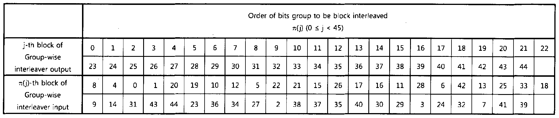


Claims

Priority Applications (7)
| Application Number | Priority Date | Filing Date | Title |
|---|---|---|---|
| MX2016015203A MX370107B (en) | 2014-05-21 | 2015-05-21 | Transmitting apparatus and interleaving method thereof. |
| EP15796379.4A EP3146636A4 (en) | 2014-05-21 | 2015-05-21 | Transmitting apparatus and interleaving method thereof |
| CN201910887090.3A CN110730004B (en) | 2014-05-21 | 2015-05-21 | Transmission apparatus and interleaving method thereof |
| CN201910887764.XA CN110719109B (en) | 2014-05-21 | 2015-05-21 | Transmission apparatus and interleaving method thereof |
| CA2949371A CA2949371C (en) | 2014-05-21 | 2015-05-21 | Transmitting apparatus and interleaving method thereof |
| CN201580027204.7A CN106416084B (en) | 2014-05-21 | 2015-05-21 | Transmission device and its deinterleaving method |
| BR112016027103-3A BR112016027103B1 (en) | 2014-05-21 | 2015-05-21 | TRANSMISSION APPARATUS, AND METHOD OF INTERFERING A TRANSMISSION APPARATUS |
Applications Claiming Priority (4)
| Application Number | Priority Date | Filing Date | Title |
|---|---|---|---|
| US201462001168P | 2014-05-21 | 2014-05-21 | |
| US62/001,168 | 2014-05-21 | ||
| KR10-2015-0000672 | 2015-01-05 | ||
| KR1020150000672A KR101775703B1 (en) | 2014-05-21 | 2015-01-05 | Transmitting apparatus and interleaving method thereof |
Publications (1)
| Publication Number | Publication Date |
|---|---|
| WO2015178695A1 true WO2015178695A1 (en) | 2015-11-26 |
Family
ID=54554290
Family Applications (1)
| Application Number | Title | Priority Date | Filing Date |
|---|---|---|---|
| PCT/KR2015/005101 WO2015178695A1 (en) | 2014-05-21 | 2015-05-21 | Transmitting apparatus and interleaving method thereof |
Country Status (4)
| Country | Link |
|---|---|
| US (3) | US9602245B2 (en) |
| CN (2) | CN110719109B (en) |
| BR (1) | BR112016027103B1 (en) |
| WO (1) | WO2015178695A1 (en) |
Cited By (1)
| Publication number | Priority date | Publication date | Assignee | Title |
|---|---|---|---|---|
| GB2539662A (en) * | 2015-06-22 | 2016-12-28 | Sony Corp | Transmitter and Receiver and Methods of Trasmitting and Receiving |
Families Citing this family (38)
| Publication number | Priority date | Publication date | Assignee | Title |
|---|---|---|---|---|
| EP3028456A4 (en) * | 2013-08-01 | 2017-04-12 | LG Electronics Inc. | Apparatus for transmitting broadcast signals, apparatus for receiving broadcast signals, method for transmitting broadcast signals and method for receiving broadcast signals |
| CN105493461B (en) * | 2013-08-01 | 2019-04-09 | Lg 电子株式会社 | The equipment for sending broadcast singal, the equipment for receiving broadcast singal, the method for sending broadcast singal and the method for receiving broadcast singal |
| CA2940197C (en) * | 2014-02-20 | 2022-07-26 | Shanghai National Engineering Research Center Of Digital Television Co., Ltd | Interleaving and mapping method and deinterleaving and demapping method for ldpc codeword |
| KR101776272B1 (en) | 2014-03-19 | 2017-09-07 | 삼성전자주식회사 | Transmitting apparatus and interleaving method thereof |
| WO2015142076A1 (en) | 2014-03-19 | 2015-09-24 | Samsung Electronics Co., Ltd. | Transmitting apparatus and interleaving method thereof |
| US9800269B2 (en) * | 2014-05-21 | 2017-10-24 | Samsung Electronics Co., Ltd. | Transmitting apparatus and interleaving method thereof |
| KR101785692B1 (en) * | 2014-05-21 | 2017-10-16 | 삼성전자주식회사 | Transmitting apparatus and interleaving method thereof |
| US9780808B2 (en) * | 2014-05-21 | 2017-10-03 | Samsung Electronics Co., Ltd. | Transmitter apparatus and bit interleaving method thereof |
| US9602245B2 (en) * | 2014-05-21 | 2017-03-21 | Samsung Electronics Co., Ltd. | Transmitting apparatus and interleaving method thereof |
| KR101775704B1 (en) | 2014-05-21 | 2017-09-19 | 삼성전자주식회사 | Transmitting apparatus and interleaving method thereof |
| KR101775703B1 (en) | 2014-05-21 | 2017-09-06 | 삼성전자주식회사 | Transmitting apparatus and interleaving method thereof |
| US9496896B2 (en) * | 2014-08-14 | 2016-11-15 | Electronics And Telecommunications Research Institute | Low density parity check encoder having length of 64800 and code rate of 5/15, and low density parity check encoding method using the same |
| US9479289B2 (en) * | 2014-08-14 | 2016-10-25 | Electronics And Telecommunications Research Institute | Low density parity check encoder having length of 16200 and code rate of 5/15, and low density parity check encoding method using the same |
| CA2864650C (en) * | 2014-08-14 | 2017-05-30 | Sung-Ik Park | Low density parity check encoder having length of 64800 and code rate of 2/15, and low density parity check encoding method using the same |
| WO2016027965A1 (en) * | 2014-08-21 | 2016-02-25 | 엘지전자 주식회사 | Apparatus for transmitting broadcast signal, apparatus for receiving broadcast signal, method for transmitting broadcast signal, and method for receiving broadcast signal |
| CN106797486B (en) | 2014-10-12 | 2020-10-16 | Lg 电子株式会社 | Broadcast signal transmitting device, broadcast signal receiving device, broadcast signal transmitting method, and broadcast signal receiving method |
| KR101764637B1 (en) | 2014-12-05 | 2017-08-14 | 엘지전자 주식회사 | Apparatus for transmitting broadcast signal, apparatus for receiving broadcast signal, method for transmitting broadcast signal and method for receiving broadcast signal |
| US10057211B2 (en) | 2014-12-10 | 2018-08-21 | Lg Electronics Inc. | Apparatus for transmitting broadcast signal, apparatus for receiving broadcast signal, method for transmitting broadcast signal and method for receiving broadcast signal |
| KR102031597B1 (en) * | 2014-12-11 | 2019-10-14 | 후아웨이 테크놀러지 컴퍼니 리미티드 | Data transmission method, transmit end device and receive end device |
| US9762354B2 (en) | 2015-01-27 | 2017-09-12 | Sony Corporation | Signaling methods and apparatus |
| KR102287621B1 (en) * | 2015-02-16 | 2021-08-10 | 한국전자통신연구원 | Bit interleaver for 256-symbol mapping and low density parity check codeword with 64800 length, 3/15 rate, and method using the same |
| EP3267692A4 (en) * | 2015-03-04 | 2018-12-05 | Sony Corporation | Transmission device, transmission method, receiving device, and receiving method |
| CN106416111B (en) | 2015-03-24 | 2020-01-17 | Lg电子株式会社 | Apparatus and method for transmitting and receiving broadcast signal |
| CN107431562B (en) * | 2015-04-06 | 2021-06-18 | Lg电子株式会社 | Apparatus and method for transmitting and receiving broadcast signal |
| US9748975B2 (en) * | 2015-05-19 | 2017-08-29 | Samsung Electronics Co., Ltd. | Transmitting apparatus and interleaving method thereof |
| US10447428B2 (en) | 2015-05-19 | 2019-10-15 | Samsung Electronics Co., Ltd. | Transmitting apparatus and interleaving method thereof |
| US10340954B2 (en) | 2015-05-19 | 2019-07-02 | Samsung Electronics Co., Ltd. | Transmitting apparatus and interleaving method thereof |
| US9729174B2 (en) | 2015-05-19 | 2017-08-08 | Samsung Electronics Co., Ltd. | Transmitting apparatus and interleaving method thereof |
| WO2017204369A1 (en) * | 2016-05-24 | 2017-11-30 | 엘지전자(주) | Device and method for receiving broadcast signal |
| US10742326B1 (en) | 2019-04-18 | 2020-08-11 | Microsoft Technology Licensing, Llc | Power-based encoding of data to be transmitted over an optical communication path |
| US11075656B2 (en) | 2019-07-16 | 2021-07-27 | Microsoft Technology Licensing, Llc | Bit error reduction of communication systems using error correction |
| US10911284B1 (en) | 2019-07-16 | 2021-02-02 | Microsoft Technology Licensing, Llc | Intelligent optimization of communication systems utilizing error correction |
| US11172455B2 (en) | 2019-07-16 | 2021-11-09 | Microsoft Technology Licensing, Llc | Peak to average power output reduction of RF systems utilizing error correction |
| US11044044B2 (en) | 2019-07-16 | 2021-06-22 | Microsoft Technology Licensing, Llc | Peak to average power ratio reduction of optical systems utilizing error correction |
| US11063696B2 (en) | 2019-07-16 | 2021-07-13 | Microsoft Technology Licensing, Llc | Increasing average power levels to reduce peak-to-average power levels using error correction codes |
| US11086719B2 (en) | 2019-07-16 | 2021-08-10 | Microsoft Technology Licensing, Llc | Use of error correction codes to prevent errors in neighboring storage |
| US11031961B2 (en) | 2019-07-16 | 2021-06-08 | Microsoft Technology Licensing, Llc | Smart symbol changes for optimization of communications using error correction |
| US10911141B1 (en) * | 2019-07-30 | 2021-02-02 | Microsoft Technology Licensing, Llc | Dynamically selecting a channel model for optical communications |
Citations (6)
| Publication number | Priority date | Publication date | Assignee | Title |
|---|---|---|---|---|
| US20090063929A1 (en) * | 2007-08-28 | 2009-03-05 | Samsung Electronics Co., Ltd. | Apparatus and method for transmitting and receiving data in a communication system using low density parity check codes |
| US20090158129A1 (en) * | 2007-12-06 | 2009-06-18 | Seho Myung | Method and apparatus for encoding and decoding channel in a communication system using low-density parity-check codes |
| US20110119568A1 (en) * | 2009-11-18 | 2011-05-19 | Samsung Electronics Co., Ltd. | Method and apparatus for transmitting and receiving data in a communication system |
| US20120051460A1 (en) * | 2010-08-26 | 2012-03-01 | Samsung Electronics Co., Ltd. | Apparatus and method for transmitting and receiving data in a communication or broadcasting system using linear block code |
| EP2560310A1 (en) | 2011-08-17 | 2013-02-20 | Panasonic Corporation | Cyclic-block permutations for spatial multiplexing with quasi-cyclic LDPC codes |
| EP3247043A1 (en) | 2015-01-13 | 2017-11-22 | Sony Corporation | Data processing device and data processing method |
Family Cites Families (28)
| Publication number | Priority date | Publication date | Assignee | Title |
|---|---|---|---|---|
| KR100683600B1 (en) | 2002-07-03 | 2007-02-16 | 휴우즈 일렉트로닉스 코오포레이션 | Encoding of low-density parity check codes using a structured parity check matrix |
| GB2454195A (en) * | 2007-10-30 | 2009-05-06 | Sony Corp | Address generation polynomial and permutation matrix for DVB-T2 16k OFDM sub-carrier mode interleaver |
| US7570698B2 (en) | 2004-11-16 | 2009-08-04 | Intel Corporation | Multiple output multicarrier transmitter and methods for spatial interleaving a plurality of spatial streams |
| US7555696B2 (en) | 2004-12-09 | 2009-06-30 | General Instrument Corporation | Method and apparatus for forward error correction in a content distribution system |
| EP2056510B1 (en) * | 2007-10-30 | 2013-04-03 | Sony Corporation | Data processing apparatus and method |
| KR101435681B1 (en) * | 2007-11-08 | 2014-09-02 | 삼성전자주식회사 | Method and apparatus for transmitting and receiving data in a communication system using low density parity check code |
| CN101911505B (en) | 2007-11-26 | 2015-05-06 | 索尼公司 | Coding device and coding method for use in transmission system |
| GB2460459B (en) * | 2008-05-30 | 2012-07-11 | Sony Corp | Data processing apparatus and method |
| KR101630442B1 (en) * | 2008-10-03 | 2016-06-24 | 톰슨 라이센싱 | Method and Apparatus for Adapting a Bit Interleaver to LDPC Codes and Modulations under AWGN Channel Conditions Using Binary Erasure Surrogate Channels |
| TWI427936B (en) * | 2009-05-29 | 2014-02-21 | Sony Corp | Receiving apparatus, receiving method, program, and receiving system |
| EP2282470A1 (en) * | 2009-08-07 | 2011-02-09 | Thomson Licensing | Data reception using low density parity check coding and constellation mapping |
| KR20110055410A (en) * | 2009-11-18 | 2011-05-25 | 삼성전자주식회사 | Method and apparatus for transmitting and receiving data in communication system |
| JP5601182B2 (en) | 2010-12-07 | 2014-10-08 | ソニー株式会社 | Data processing apparatus and data processing method |
| JP5630282B2 (en) | 2011-01-19 | 2014-11-26 | ソニー株式会社 | Data processing apparatus and data processing method |
| JP5637393B2 (en) | 2011-04-28 | 2014-12-10 | ソニー株式会社 | Data processing apparatus and data processing method |
| EP2536030A1 (en) * | 2011-06-16 | 2012-12-19 | Panasonic Corporation | Bit permutation patterns for BICM with LDPC codes and QAM constellations |
| EP2690790A1 (en) | 2012-07-27 | 2014-01-29 | Panasonic Corporation | Bit interleaving for rotated constellations with quasi-cyclic LDPC codes |
| KR20150005853A (en) * | 2013-07-05 | 2015-01-15 | 삼성전자주식회사 | transmitter apparatus and signal processing method thereof |
| US9577679B2 (en) * | 2013-10-04 | 2017-02-21 | Samsung Electronics Co., Ltd. | Transmitting apparatus and signal processing method thereof |
| US9871621B2 (en) * | 2013-10-30 | 2018-01-16 | Samsung Electronics Co., Ltd. | Transmitting apparatus and signal processing method thereof |
| US10425110B2 (en) * | 2014-02-19 | 2019-09-24 | Samsung Electronics Co., Ltd. | Transmitting apparatus and interleaving method thereof |
| US9602137B2 (en) * | 2014-02-19 | 2017-03-21 | Samsung Electronics Co., Ltd. | Transmitting apparatus and interleaving method thereof |
| US9596116B2 (en) * | 2014-02-20 | 2017-03-14 | Lg Electronics Inc. | Apparatus for transmitting broadcast signals, apparatus for receiving broadcast signals, method for transmitting broadcast signals and method for receiving broadcast signals |
| WO2015142076A1 (en) * | 2014-03-19 | 2015-09-24 | Samsung Electronics Co., Ltd. | Transmitting apparatus and interleaving method thereof |
| US9800269B2 (en) * | 2014-05-21 | 2017-10-24 | Samsung Electronics Co., Ltd. | Transmitting apparatus and interleaving method thereof |
| US9780808B2 (en) * | 2014-05-21 | 2017-10-03 | Samsung Electronics Co., Ltd. | Transmitter apparatus and bit interleaving method thereof |
| US9602245B2 (en) * | 2014-05-21 | 2017-03-21 | Samsung Electronics Co., Ltd. | Transmitting apparatus and interleaving method thereof |
| US10396824B2 (en) * | 2014-05-21 | 2019-08-27 | Sony Corporation | Data processing device and data processing method |
-
2015
- 2015-05-19 US US14/716,124 patent/US9602245B2/en active Active
- 2015-05-21 BR BR112016027103-3A patent/BR112016027103B1/en active IP Right Grant
- 2015-05-21 CN CN201910887764.XA patent/CN110719109B/en active Active
- 2015-05-21 CN CN201910887090.3A patent/CN110730004B/en active Active
- 2015-05-21 WO PCT/KR2015/005101 patent/WO2015178695A1/en active Application Filing
-
2016
- 2016-04-15 US US15/130,154 patent/US9614644B2/en active Active
-
2017
- 2017-02-14 US US15/432,078 patent/US10355817B2/en active Active
Patent Citations (7)
| Publication number | Priority date | Publication date | Assignee | Title |
|---|---|---|---|---|
| US20090063929A1 (en) * | 2007-08-28 | 2009-03-05 | Samsung Electronics Co., Ltd. | Apparatus and method for transmitting and receiving data in a communication system using low density parity check codes |
| US20090158129A1 (en) * | 2007-12-06 | 2009-06-18 | Seho Myung | Method and apparatus for encoding and decoding channel in a communication system using low-density parity-check codes |
| US20110119568A1 (en) * | 2009-11-18 | 2011-05-19 | Samsung Electronics Co., Ltd. | Method and apparatus for transmitting and receiving data in a communication system |
| US20120051460A1 (en) * | 2010-08-26 | 2012-03-01 | Samsung Electronics Co., Ltd. | Apparatus and method for transmitting and receiving data in a communication or broadcasting system using linear block code |
| EP2560310A1 (en) | 2011-08-17 | 2013-02-20 | Panasonic Corporation | Cyclic-block permutations for spatial multiplexing with quasi-cyclic LDPC codes |
| US20130216001A1 (en) * | 2011-08-17 | 2013-08-22 | Mihail Petrov | Interleaving method and deinterleaving method |
| EP3247043A1 (en) | 2015-01-13 | 2017-11-22 | Sony Corporation | Data processing device and data processing method |
Non-Patent Citations (1)
| Title |
|---|
| See also references of EP3146636A4 |
Cited By (5)
| Publication number | Priority date | Publication date | Assignee | Title |
|---|---|---|---|---|
| GB2539662A (en) * | 2015-06-22 | 2016-12-28 | Sony Corp | Transmitter and Receiver and Methods of Trasmitting and Receiving |
| US10469220B2 (en) | 2015-06-22 | 2019-11-05 | Sony Corporation | Transmitter and receiver and methods of transmitting and receiving |
| US10911194B2 (en) | 2015-06-22 | 2021-02-02 | Saturn Licensing Llc | Transmitter and receiver and methods of transmitting and receiving |
| US11025381B2 (en) | 2015-06-22 | 2021-06-01 | Saturn Licensing Llc | Transmitter and receiver and methods of transmitting and receiving |
| US11646839B2 (en) | 2015-06-22 | 2023-05-09 | Saturn Licensing Llc | Transmitter and receiver and methods of transmitting and receiving |
Also Published As
| Publication number | Publication date |
|---|---|
| US9602245B2 (en) | 2017-03-21 |
| CN110719109A (en) | 2020-01-21 |
| CN110730004B (en) | 2023-06-20 |
| BR112016027103B1 (en) | 2023-04-04 |
| CN110719109B (en) | 2023-06-27 |
| US10355817B2 (en) | 2019-07-16 |
| BR112016027103A2 (en) | 2017-08-15 |
| US20150341052A1 (en) | 2015-11-26 |
| CN110730004A (en) | 2020-01-24 |
| US20160233983A1 (en) | 2016-08-11 |
| US9614644B2 (en) | 2017-04-04 |
| US20170155473A1 (en) | 2017-06-01 |
Similar Documents
| Publication | Publication Date | Title |
|---|---|---|
| US20220278694A1 (en) | Transmitting apparatus and bit interleaving method thereof | |
| WO2015178695A1 (en) | Transmitting apparatus and interleaving method thereof | |
| US10367533B2 (en) | Transmitting apparatus and interleaving method thereof | |
| US9847794B2 (en) | Transmitting apparatus and interleaving method thereof | |
| US11949433B2 (en) | Transmitting apparatus and interleaving method thereof | |
| US10367532B2 (en) | Transmitting apparatus and interleaving method thereof | |
| US11637655B2 (en) | Transmitting apparatus and interleaving method thereof | |
| US9748975B2 (en) | Transmitting apparatus and interleaving method thereof | |
| EP3146637A1 (en) | Transmitting apparatus and interleaving method thereof | |
| US11057056B2 (en) | Transmitting apparatus and interleaving method thereof | |
| US10367531B2 (en) | Transmitting apparatus and interleaving method thereof | |
| US10439646B2 (en) | Transmitting apparatus and interleaving method thereof | |
| US11043974B2 (en) | Transmitting apparatus and interleaving method thereof | |
| US9716516B2 (en) | Transmitting apparatus and interleaving method thereof |
Legal Events
| Date | Code | Title | Description |
|---|---|---|---|
| 121 | Ep: the epo has been informed by wipo that ep was designated in this application |
Ref document number: 15796379 Country of ref document: EP Kind code of ref document: A1 |
|
| ENP | Entry into the national phase |
Ref document number: 2949371 Country of ref document: CA |
|
| REEP | Request for entry into the european phase |
Ref document number: 2015796379 Country of ref document: EP |
|
| WWE | Wipo information: entry into national phase |
Ref document number: 2015796379 Country of ref document: EP |
|
| WWE | Wipo information: entry into national phase |
Ref document number: MX/A/2016/015203 Country of ref document: MX |
|
| NENP | Non-entry into the national phase |
Ref country code: DE |
|
| REG | Reference to national code |
Ref country code: BR Ref legal event code: B01A Ref document number: 112016027103 Country of ref document: BR |
|
| ENP | Entry into the national phase |
Ref document number: 112016027103 Country of ref document: BR Kind code of ref document: A2 Effective date: 20161118 |