WO2015174108A1 - Communication apparatus, communication method, and computer program - Google Patents
Communication apparatus, communication method, and computer program Download PDFInfo
- Publication number
- WO2015174108A1 WO2015174108A1 PCT/JP2015/054037 JP2015054037W WO2015174108A1 WO 2015174108 A1 WO2015174108 A1 WO 2015174108A1 JP 2015054037 W JP2015054037 W JP 2015054037W WO 2015174108 A1 WO2015174108 A1 WO 2015174108A1
- Authority
- WO
- WIPO (PCT)
- Prior art keywords
- transmission
- dynamic range
- information
- hdmi
- range conversion
- Prior art date
Links
- 230000006854 communication Effects 0.000 title claims description 78
- 238000004891 communication Methods 0.000 title claims description 78
- 238000000034 method Methods 0.000 title claims description 68
- 238000004590 computer program Methods 0.000 title claims description 18
- 230000005540 biological transmission Effects 0.000 claims abstract description 454
- 238000006243 chemical reaction Methods 0.000 claims abstract description 371
- 230000007175 bidirectional communication Effects 0.000 claims description 32
- 238000005513 bias potential Methods 0.000 claims description 10
- 238000012545 processing Methods 0.000 abstract description 70
- 210000003127 knee Anatomy 0.000 description 68
- 238000005516 engineering process Methods 0.000 description 32
- RTZKZFJDLAIYFH-UHFFFAOYSA-N Diethyl ether Chemical compound CCOCC RTZKZFJDLAIYFH-UHFFFAOYSA-N 0.000 description 28
- 238000010586 diagram Methods 0.000 description 19
- 230000006870 function Effects 0.000 description 18
- 230000002688 persistence Effects 0.000 description 18
- 230000008569 process Effects 0.000 description 16
- 230000006835 compression Effects 0.000 description 15
- 238000007906 compression Methods 0.000 description 15
- 230000005236 sound signal Effects 0.000 description 10
- 230000004044 response Effects 0.000 description 8
- 230000002441 reversible effect Effects 0.000 description 8
- 101150002258 HDR1 gene Proteins 0.000 description 6
- 238000001514 detection method Methods 0.000 description 6
- 101100070271 Oryza sativa subsp. japonica HDR3 gene Proteins 0.000 description 5
- 230000006837 decompression Effects 0.000 description 5
- 230000000694 effects Effects 0.000 description 5
- 230000003321 amplification Effects 0.000 description 4
- 238000003199 nucleic acid amplification method Methods 0.000 description 4
- 230000000007 visual effect Effects 0.000 description 4
- 230000003252 repetitive effect Effects 0.000 description 3
- 230000000717 retained effect Effects 0.000 description 3
- 230000000630 rising effect Effects 0.000 description 3
- 230000001360 synchronised effect Effects 0.000 description 3
- 230000008901 benefit Effects 0.000 description 2
- 230000002457 bidirectional effect Effects 0.000 description 2
- 238000005401 electroluminescence Methods 0.000 description 2
- 239000004973 liquid crystal related substance Substances 0.000 description 2
- 230000004048 modification Effects 0.000 description 2
- 238000012986 modification Methods 0.000 description 2
- 230000000153 supplemental effect Effects 0.000 description 2
- 230000009466 transformation Effects 0.000 description 2
- 230000002730 additional effect Effects 0.000 description 1
- 230000008859 change Effects 0.000 description 1
- 239000003999 initiator Substances 0.000 description 1
- 230000007246 mechanism Effects 0.000 description 1
- 239000013307 optical fiber Substances 0.000 description 1
- 230000002093 peripheral effect Effects 0.000 description 1
- 230000008054 signal transmission Effects 0.000 description 1
- 230000011664 signaling Effects 0.000 description 1
- 239000007787 solid Substances 0.000 description 1
- 238000006467 substitution reaction Methods 0.000 description 1
- 238000012546 transfer Methods 0.000 description 1
- 230000001131 transforming effect Effects 0.000 description 1
- 230000007704 transition Effects 0.000 description 1
Images


Classifications
-
- H—ELECTRICITY
- H04—ELECTRIC COMMUNICATION TECHNIQUE
- H04N—PICTORIAL COMMUNICATION, e.g. TELEVISION
- H04N7/00—Television systems
- H04N7/08—Systems for the simultaneous or sequential transmission of more than one television signal, e.g. additional information signals, the signals occupying wholly or partially the same frequency band, e.g. by time division
- H04N7/081—Systems for the simultaneous or sequential transmission of more than one television signal, e.g. additional information signals, the signals occupying wholly or partially the same frequency band, e.g. by time division the additional information signals being transmitted by means of a subcarrier
-
- G—PHYSICS
- G09—EDUCATION; CRYPTOGRAPHY; DISPLAY; ADVERTISING; SEALS
- G09G—ARRANGEMENTS OR CIRCUITS FOR CONTROL OF INDICATING DEVICES USING STATIC MEANS TO PRESENT VARIABLE INFORMATION
- G09G5/00—Control arrangements or circuits for visual indicators common to cathode-ray tube indicators and other visual indicators
- G09G5/003—Details of a display terminal, the details relating to the control arrangement of the display terminal and to the interfaces thereto
- G09G5/006—Details of the interface to the display terminal
-
- H—ELECTRICITY
- H04—ELECTRIC COMMUNICATION TECHNIQUE
- H04N—PICTORIAL COMMUNICATION, e.g. TELEVISION
- H04N19/00—Methods or arrangements for coding, decoding, compressing or decompressing digital video signals
- H04N19/90—Methods or arrangements for coding, decoding, compressing or decompressing digital video signals using coding techniques not provided for in groups H04N19/10-H04N19/85, e.g. fractals
- H04N19/98—Adaptive-dynamic-range coding [ADRC]
-
- H—ELECTRICITY
- H04—ELECTRIC COMMUNICATION TECHNIQUE
- H04N—PICTORIAL COMMUNICATION, e.g. TELEVISION
- H04N21/00—Selective content distribution, e.g. interactive television or video on demand [VOD]
- H04N21/40—Client devices specifically adapted for the reception of or interaction with content, e.g. set-top-box [STB]; Operations thereof
- H04N21/41—Structure of client; Structure of client peripherals
- H04N21/422—Input-only peripherals, i.e. input devices connected to specially adapted client devices, e.g. global positioning system [GPS]
- H04N21/42204—User interfaces specially adapted for controlling a client device through a remote control device; Remote control devices therefor
-
- H—ELECTRICITY
- H04—ELECTRIC COMMUNICATION TECHNIQUE
- H04N—PICTORIAL COMMUNICATION, e.g. TELEVISION
- H04N21/00—Selective content distribution, e.g. interactive television or video on demand [VOD]
- H04N21/40—Client devices specifically adapted for the reception of or interaction with content, e.g. set-top-box [STB]; Operations thereof
- H04N21/43—Processing of content or additional data, e.g. demultiplexing additional data from a digital video stream; Elementary client operations, e.g. monitoring of home network or synchronising decoder's clock; Client middleware
- H04N21/4302—Content synchronisation processes, e.g. decoder synchronisation
- H04N21/4307—Synchronising the rendering of multiple content streams or additional data on devices, e.g. synchronisation of audio on a mobile phone with the video output on the TV screen
-
- H—ELECTRICITY
- H04—ELECTRIC COMMUNICATION TECHNIQUE
- H04N—PICTORIAL COMMUNICATION, e.g. TELEVISION
- H04N21/00—Selective content distribution, e.g. interactive television or video on demand [VOD]
- H04N21/40—Client devices specifically adapted for the reception of or interaction with content, e.g. set-top-box [STB]; Operations thereof
- H04N21/43—Processing of content or additional data, e.g. demultiplexing additional data from a digital video stream; Elementary client operations, e.g. monitoring of home network or synchronising decoder's clock; Client middleware
- H04N21/436—Interfacing a local distribution network, e.g. communicating with another STB or one or more peripheral devices inside the home
- H04N21/4363—Adapting the video stream to a specific local network, e.g. a Bluetooth® network
- H04N21/43632—Adapting the video stream to a specific local network, e.g. a Bluetooth® network involving a wired protocol, e.g. IEEE 1394
- H04N21/43635—HDMI
-
- H—ELECTRICITY
- H04—ELECTRIC COMMUNICATION TECHNIQUE
- H04N—PICTORIAL COMMUNICATION, e.g. TELEVISION
- H04N21/00—Selective content distribution, e.g. interactive television or video on demand [VOD]
- H04N21/40—Client devices specifically adapted for the reception of or interaction with content, e.g. set-top-box [STB]; Operations thereof
- H04N21/43—Processing of content or additional data, e.g. demultiplexing additional data from a digital video stream; Elementary client operations, e.g. monitoring of home network or synchronising decoder's clock; Client middleware
- H04N21/44—Processing of video elementary streams, e.g. splicing a video clip retrieved from local storage with an incoming video stream or rendering scenes according to encoded video stream scene graphs
- H04N21/4402—Processing of video elementary streams, e.g. splicing a video clip retrieved from local storage with an incoming video stream or rendering scenes according to encoded video stream scene graphs involving reformatting operations of video signals for household redistribution, storage or real-time display
-
- H—ELECTRICITY
- H04—ELECTRIC COMMUNICATION TECHNIQUE
- H04N—PICTORIAL COMMUNICATION, e.g. TELEVISION
- H04N7/00—Television systems
- H04N7/10—Adaptations for transmission by electrical cable
- H04N7/108—Adaptations for transmission by electrical cable the cable being constituted by a pair of wires
-
- G—PHYSICS
- G06—COMPUTING; CALCULATING OR COUNTING
- G06T—IMAGE DATA PROCESSING OR GENERATION, IN GENERAL
- G06T2207/00—Indexing scheme for image analysis or image enhancement
- G06T2207/20—Special algorithmic details
- G06T2207/20172—Image enhancement details
- G06T2207/20208—High dynamic range [HDR] image processing
-
- G—PHYSICS
- G09—EDUCATION; CRYPTOGRAPHY; DISPLAY; ADVERTISING; SEALS
- G09G—ARRANGEMENTS OR CIRCUITS FOR CONTROL OF INDICATING DEVICES USING STATIC MEANS TO PRESENT VARIABLE INFORMATION
- G09G2340/00—Aspects of display data processing
- G09G2340/02—Handling of images in compressed format, e.g. JPEG, MPEG
-
- G—PHYSICS
- G09—EDUCATION; CRYPTOGRAPHY; DISPLAY; ADVERTISING; SEALS
- G09G—ARRANGEMENTS OR CIRCUITS FOR CONTROL OF INDICATING DEVICES USING STATIC MEANS TO PRESENT VARIABLE INFORMATION
- G09G2360/00—Aspects of the architecture of display systems
- G09G2360/12—Frame memory handling
- G09G2360/128—Frame memory using a Synchronous Dynamic RAM [SDRAM]
-
- G—PHYSICS
- G09—EDUCATION; CRYPTOGRAPHY; DISPLAY; ADVERTISING; SEALS
- G09G—ARRANGEMENTS OR CIRCUITS FOR CONTROL OF INDICATING DEVICES USING STATIC MEANS TO PRESENT VARIABLE INFORMATION
- G09G2370/00—Aspects of data communication
- G09G2370/04—Exchange of auxiliary data, i.e. other than image data, between monitor and graphics controller
- G09G2370/045—Exchange of auxiliary data, i.e. other than image data, between monitor and graphics controller using multiple communication channels, e.g. parallel and serial
- G09G2370/047—Exchange of auxiliary data, i.e. other than image data, between monitor and graphics controller using multiple communication channels, e.g. parallel and serial using display data channel standard [DDC] communication
-
- G—PHYSICS
- G09—EDUCATION; CRYPTOGRAPHY; DISPLAY; ADVERTISING; SEALS
- G09G—ARRANGEMENTS OR CIRCUITS FOR CONTROL OF INDICATING DEVICES USING STATIC MEANS TO PRESENT VARIABLE INFORMATION
- G09G2370/00—Aspects of data communication
- G09G2370/06—Consumer Electronics Control, i.e. control of another device by a display or vice versa
-
- G—PHYSICS
- G09—EDUCATION; CRYPTOGRAPHY; DISPLAY; ADVERTISING; SEALS
- G09G—ARRANGEMENTS OR CIRCUITS FOR CONTROL OF INDICATING DEVICES USING STATIC MEANS TO PRESENT VARIABLE INFORMATION
- G09G2370/00—Aspects of data communication
- G09G2370/12—Use of DVI or HDMI protocol in interfaces along the display data pipeline
Definitions
- the technology disclosed in the present specification relates to a communication apparatus and communication method for transmitting and receiving data, and a computer program.
- a computer program for example, a communication apparatus and communication method for transmitting and receiving uncompressed image data transmitted through a digital interface such as HDMI.
- a digital interface such as HDMI.
- computer programs for example, a communication apparatus and communication method for transmitting and receiving uncompressed image data transmitted through a digital interface such as HDMI.
- HDMI registered trademark
- High Definition Multimedia has been used as a communication interface for transmitting uncompressed (baseband) image signals (image data) and digital audio signals (audio data) accompanying the image signals at high speed. Interface
- the data transmission side connected via the HDMI interface is an HDMI source device
- the data reception side is an HDMI sink device.
- a BD (Blu-Ray Disc) recorder or STB (Set Top Box) as an HDMI source device
- other AV sources Audio Visual Source
- a television receiver, projector, or other display as an HDMI sink device
- An AV system connected via an HDMI interface can be considered.
- an HDMI sink device having a plurality of HDMI inputs and an input source switching function according to a user operation is known (for example, refer to Patent Documents 1 and 2).
- the HDMI source device in order to detect the HDMI input switched by the user, the hot plug signal of the HDMI terminal is detected and the output of the video / audio signal is controlled.
- the uncompressed image data output from the HDMI source device may be transmitted after performing dynamic range conversion on the original image having a dynamic range higher than the standard luminance and compressing the original image to the dynamic range of the standard luminance.
- display devices such as an organic (Organic Electro-Luminescence) display and an LCD (Liquid Crystal Display), which can display an image brighter than the standard luminance, for example, about 1000 cd / m 2 , are also available on the market.
- the HDMI sink device is a display device having such a wide dynamic range
- the image having the original high luminance dynamic range is obtained by performing inverse dynamic range conversion on the image data that has been converted into the standard luminance. By returning to the data, it is possible to display an image that takes advantage of its performance.
- HDMI input switching is performed in an HDMI sink device
- the dynamic range conversion definition information of uncompressed image data changes between HDMI source devices before and after switching
- the HDMI sink device has different dynamics.
- the dynamic range reverse conversion of the uncompressed image data is performed based on the range conversion definition information, and converted into an image having a dynamic range different from the desired dynamic range.
- An object of the technology disclosed in the present specification is to provide an excellent communication apparatus and communication method, and a computer program capable of suitably transmitting and receiving uncompressed image data subjected to dynamic range processing via a digital interface such as HDMI. It is to provide.
- the purpose of the technology disclosed in this specification is to transmit non-compressed image data that has undergone dynamic range processing via a digital interface such as HDMI and display it at an appropriate brightness in an HDMI sink device.
- a communication apparatus, a communication method, and a computer program are provided.
- a data transmission unit that transmits uncompressed image data to an external device via a transmission path;
- An information transmission unit that transmits dynamic range conversion definition information of uncompressed image data to the external device via the transmission path;
- a control receiver for receiving transmission control information of dynamic range conversion definition information from the external device via the transmission path; It is a communication apparatus which comprises.
- the control receiver of the communication device according to claim 1 is connected via a line that receives a notification of a connection state of the external device by a DC bias potential of the transmission path.
- the transmission control information is received from the external device.
- control receiving unit of the communication device performs transmission control from the external device via a predetermined control data line included in the transmission path. It is configured to receive information.
- control reception unit of the communication apparatus is configured through a bidirectional communication path configured using a predetermined line included in the transmission path, It is configured to receive transmission control information from the external device.
- the communication device includes the information transmission unit based on transmission control information received from the external device by the control reception unit. Is configured to control transmission of dynamic range conversion definition information from the device to the external device.
- a data transmission step of transmitting uncompressed image data to an external device via a transmission path An information transmission step of transmitting dynamic range conversion definition information of uncompressed image data to the external device via the transmission path;
- the technique described in claim 7 of the present application is: A data transmission unit that transmits uncompressed image data to an external device via a transmission path; An information transmission unit for transmitting dynamic range conversion definition information of uncompressed image data to the external device via the transmission path; A control receiver for receiving transmission control information of dynamic range conversion definition information from the external device via the transmission path; As a computer program written in a computer-readable format to make the computer function.
- the computer program according to claim 7 of the present application defines a computer program described in a computer-readable format so as to realize predetermined processing on a computer.
- a cooperative operation is exhibited on the computer, and the same operational effect as the communication device according to claim 1 of the present application is obtained. Can do.
- a data receiver that receives uncompressed image data from an external device via a transmission line;
- An information receiving unit for receiving dynamic range conversion definition information of uncompressed image data from the external device via the transmission path;
- a control transmitter that transmits transmission control information of dynamic range conversion definition information to the external device via the transmission path; It is a communication apparatus which comprises.
- control transmission unit of the communication device according to claim 8 is connected via a line that receives a notification of a connection state of the external device by a DC bias potential of the transmission path.
- the transmission control information is transmitted to the external device.
- control transmission unit of the communication device controls transmission to the external device via a predetermined control data line included in the transmission path. It is configured to transmit information.
- control transmission unit of the communication device is configured to pass through a bidirectional communication path configured using a predetermined line included in the transmission path.
- the transmission control information is transmitted to the external device.
- the technique according to claim 12 of the present application is A data receiving step for receiving uncompressed image data from an external device via a transmission path; An information receiving step for receiving dynamic range conversion definition information of uncompressed image data from the external device via the transmission path; A control transmission step of transmitting transmission control information of dynamic range conversion definition information to the external device via the transmission path; It is a communication apparatus which comprises.
- the technique according to claim 13 of the present application is A data receiving unit that receives uncompressed image data from an external device via a transmission line; An information receiving unit for receiving dynamic range conversion definition information of uncompressed image data from the external device via the transmission path; A control transmission unit for transmitting transmission control information of dynamic range conversion definition information to the external device via the transmission line; As a computer program written in a computer-readable format to make the computer function.
- the computer program according to claim 13 of the present application defines a computer program described in a computer-readable format so as to realize predetermined processing on a computer.
- a cooperative operation is exhibited on the computer, and the same operation effect as that of the communication device according to claim 8 of the present application is obtained. Can do.
- a communication apparatus, a communication method, and a computer program can be provided.
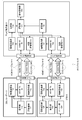
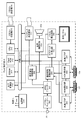
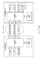
- FIG. 1 is a diagram illustrating a functional configuration example of an AV (Audio Visual) system 10 to which the technology disclosed in this specification is applied.
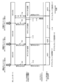
- FIG. 2 is a diagram showing the HDMI transmission unit 11b of the BD recorder 11 and the HDMI reception unit 13b of the television receiver 13 in the AV system 10 shown in FIG.
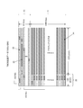
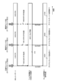
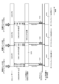
- FIG. 3 is a diagram illustrating sections of various TDMS transmission data when image data of horizontal ⁇ vertical 1920 pixels ⁇ 1080 lines is transmitted on TDMS channels # 0, # 1, and # 2.
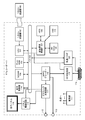
- FIG. 4 is a diagram illustrating a configuration example of the BD recorder 11.
- FIG. 5 is a diagram illustrating a configuration example of the television receiver 13.
- FIG. 1 is a diagram illustrating a functional configuration example of an AV (Audio Visual) system 10 to which the technology disclosed in this specification is applied.
- FIG. 2 is a diagram showing the HDMI transmission unit 11b of the BD recorder 11 and the HDMI reception unit 13b of the television receiver 13 in the AV system 10 shown in
- FIG. 6 is a diagram illustrating a syntax example of the dynamic range conversion definition information “knee_function_info SEI”.
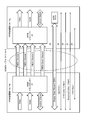
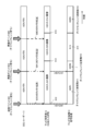
- FIG. 7 is a diagram illustrating an example of a method for transmitting dynamic range conversion definition information.
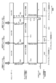
- FIG. 8 is a diagram illustrating an example of a method for thinning out and transmitting dynamic range conversion definition information.
- FIG. 9 is a diagram for explaining a problem that occurs when the dynamic range conversion definition information is thinned out and transmitted.
- FIG. 10 is a diagram illustrating an example of a method of transmitting dynamic range conversion definition information to which the technology disclosed in this specification is applied.
- FIG. 11 is a diagram illustrating another example of a transmission method of dynamic range conversion definition information to which the technology disclosed in this specification is applied.
- FIG. 12 is a diagram showing still another example of the transmission method of the dynamic range conversion definition information to which the technology disclosed in this specification is applied.
- FIG. 13 is a diagram illustrating a data structure example of a CEC packet.
- FIG. 14 is a diagram illustrating a data structure example of a bidirectional communication path.
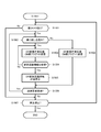
- FIG. 15 is a flowchart showing a processing procedure for performing transmission control of the dynamic range conversion definition information in the BD recorder 11.
- FIG. 16 is a flowchart showing a processing procedure for performing transmission control of dynamic range conversion definition information in the television receiver 13.
- FIG. 17 is a diagram illustrating a configuration example of a DP system 1700 using a DP interface.
- FIG. 18 is a diagram showing a structure example 1800 of a packet transmitted on the AUX channel 1705 included in the DP interface.
- FIG. 19 is a diagram illustrating a configuration example of an MHL system 1900 using an MHL interface.
- FIG. 20 is a diagram illustrating a structure example 20000 of a packet transmitted on the CBUS channel 1906.
- FIG. 21 is a diagram for explaining the dynamic range conversion definition information.
- FIG. 1 shows a functional configuration example of an AV (Audio Visual) system 10 to which the technique disclosed in this specification is applied.
- the illustrated AV system 10 includes a BD (Blu-ray Disc) recorder 11 and an STB (Set Top Box) 12 as HDMI source devices, and a television receiver 13 as an HDMI sink device.
- the BD recorder 11 and the television receiver 13 are connected via an HDMI cable 14-1 as a transmission path.
- the STB 12 and the television receiver 13 are connected via an HDMI cable 14-2 as a transmission path.
- the BD recorder 11 reads the encoded data from the storage medium 11f and decodes it into an uncompressed image, acquires the conversion definition information of the high dynamic range image from the data decoded by the decoder 11e, An information transmission unit 11d that transmits to the television receiver 13 via the HDMI cable 14-1 and an HDMI transmission unit that transmits the data decoded by the decoding unit 11e to the television receiver 13 via the HDMI cable 14-1 ( HDMI TX) 11b, a control receiver 11c that receives transmission control information from the television receiver 13, and an HDMI terminal 11a to which the HDMI transmitter 11b and the control receiver 11c are connected.
- the function of the control reception unit 11c may be implemented in the HDMI transmission unit 11b or may be realized using a high-speed bus interface (described later).
- the information transmission unit 11d inserts dynamic range conversion definition information in a blanking period (described later) of uncompressed image data transmitted from the HDMI transmission unit 11b, or uses a predetermined line included in the HDMI cable 14-1.
- a packet storing dynamic range conversion definition information is transmitted using a bidirectional communication path (described later) configured as described above.
- the control receiving unit 11c receives transmission control information (transmission request information and reception recognition information, which will be described later) of dynamic range conversion definition information from the television receiver 13.
- the BD recorder 11 has a function of encoding uncompressed image data and a function of writing image data (encoded and compressed or uncompressed) to the storage medium 11f, the illustration is omitted. .
- One end of the HDMI cable 14-1 is connected to the HDMI terminal 11a of the BD recorder 11, and the other end of the HDMI cable 14-1 is connected to the HDMI terminal 13a of the television receiver 13.
- the STB 12 is a tuner unit 12d that selects and receives a digital broadcast stream, a decoding unit 12e that reads encoded data from the digital broadcast stream received by the tuner unit 12d and decodes the encoded data into an uncompressed image, and is decoded by the decoding unit 12e.
- An information storage unit 12f that acquires and stores dynamic range conversion definition information from the data; an information transmission unit 12g that transmits the dynamic range conversion definition information to the television receiver 13 via the HDMI cable 14-2; , An HDMI transmission unit (HDMI TX) 12b for transmitting the data decoded by the decoding unit 12e to the television receiver 13 via the HDMI cable 14-2, and control reception for receiving transmission control information from the television receiver 13 Unit 12c, HDMI transmitter 12b, and control receiver 12c connected to each other It has a terminal 12a.
- the function of the control reception unit 12c may be implemented in the HDMI transmission unit 12b or may be realized using a high-speed bus interface (described later).
- the information transmission unit 12g inserts dynamic range conversion definition information in a blanking period (described later) of uncompressed image data transmitted from the HDMI transmission unit 12b, or uses a predetermined line included in the HDMI cable 14-2.
- a packet storing dynamic range conversion definition information is transmitted using a bidirectional communication path (described later) configured as described above.
- the control receiver 12c receives transmission control information (transmission request information and reception recognition information) of dynamic range conversion definition information from the television receiver 13.
- One end of the HDMI cable 14-2 is connected to the HDMI terminal 12a of the STB 12, and the other end of the HDMI cable 14-2 is connected to the HDMI terminal 13f of the television receiver 13.
- the IPTV is provided with an Ethernet (registered trademark) circuit that acquires content data on the Internet from a content server.
- the STB for Internet Protocol Television
- the STB for may have the same configuration as the STB 12 and can be applied to the AV system 10 as one of the HDMI source devices.
- the television receiver 13 includes an HDMI terminal 13a to which an HDMI receiving unit 13b that receives uncompressed image data from the BD recorder 11 and a control transmission unit 13c that transmits transmission control information to the BD recorder 11, and a transmission path 14-1.
- the information receiving unit 13d for acquiring the dynamic range conversion definition information of the uncompressed image data
- the storage unit 13e for storing the dynamic range conversion definition information received by the information receiving unit 13d
- the dynamic range conversion definition information of the uncompressed image data is acquired via the HDMI terminal 13f connected to the HDMI receiving unit 13g for receiving the transmission and the control transmitting unit 13h for transmitting the transmission control information to the STB 12, and the transmission path 14-2.
- a storage unit 13j that stores definition information, a selection unit 13k that selects one of the plurality of HDMI terminals 13a or 13f as an HDMI input, and a signal that performs dynamic range conversion processing of the selected uncompressed image data
- a processing unit 13m is provided.
- the selection unit 13k switches the HDMI input in accordance with, for example, a user operation on a user operation unit (not shown).
- the function of the control reception unit 11c may be implemented in the HDMI transmission unit 11b or may be realized using a high-speed bus interface (described later).
- the information receiving unit 13d / 13i receives the dynamic range conversion definition information inserted in the blanking period of the uncompressed image data transmitted via the HDMI cable 14-1 / 14-2, or receives the HDMI cable 14-
- the dynamic range conversion definition information is received via a bidirectional communication path (described later) configured using a predetermined line included in 1 / 14-2.
- the control transmitter 13c / 13h transmits transmission control information (transmission request information and reception recognition information: described later) of dynamic range conversion definition information to the BD recorder 11 and the STB 12.
- the control transmission unit 13c / 13h is connected via a bidirectional communication path configured using a device connection detection line, a control data line, or a predetermined line included in the HDMI cable 14-1 / 14-2. Transmission control information can be transmitted (described later).
- HDMI transmission unit 11b, the control reception unit 11c, and the information transmission unit 11d of the BD recorder 11 may be configured as one chip or a plurality of cores. Further, the control reception unit 11c and the information transmission unit 11d may be a high-speed bus interface 120 (HEC line: described later) configured by a predetermined line included in the HDMI cable 14-1.
- HDMI line high-speed bus interface 120
- the HDMI transmission unit 12b, the control reception unit 12c, the information reception unit 12g, and the information storage unit 12f of the STB 12 may be configured as one chip or a plurality of cores. Further, the control receiving unit 12c and the information transmitting unit 12g may be a high-speed bus interface (described later) configured by a predetermined line included in the HDMI cable 14-2.
- the HDMI receiving unit 13b / 13g, the control transmitting unit 13c / 13h, the storage unit 13e / 13j, and the selecting unit 13k of the television receiver 13 may be configured as one chip or a plurality of cores. Good. Further, the control transmission unit 13c / 13h and the information reception unit 13d / 13i may be a high-speed bus interface 120 (described later) configured by a predetermined line included in the HDMI cable 14-1.
- the uncompressed image data read from the storage medium 11f in the BD recorder 11 and decoded by the decoding unit 11e is originally uncompressed image data having a wide luminance dynamic range, but has been converted to a dynamic range of standard luminance. Is. That is, from the BD recorder 11 as the HDMI source device, an original image having a dynamic range equal to or higher than the standard luminance is changed to the standard luminance dynamic range and transmitted to the television receiver 13.
- uncompressed image data received by the tuner unit 12d in the STB 12 and decoded by the decoding unit 12e is originally uncompressed image data having a wide luminance dynamic range, but has been converted to a standard luminance dynamic range. Is. That is, from the STB 12 as the HDMI source device, an original image having a dynamic range equal to or higher than the standard luminance is changed to the standard luminance dynamic range and transmitted to the television receiver 13.
- the television receiver 13 includes a display device such as an organic display or LCD capable of displaying an image brighter than the standard luminance, for example, about 1000 cd / m 2 .
- a display device such as an organic display or LCD capable of displaying an image brighter than the standard luminance, for example, about 1000 cd / m 2 .
- the dynamic range reverse conversion is performed on the image data that has been subjected to the dynamic range conversion to the standard luminance, and the original image data having a high luminance dynamic range is restored. Therefore, it is desired to perform image display that makes use of the performance.
- each of the BD recorder 11 and the STB 12 as the HDMI source device transmits the dynamic range conversion definition information to the information transmission unit when transmitting uncompressed image data from the HDMI transmission unit 11b or 12b. Transmit from 11d or 12g.
- the HDMI sink device side performs an inverse dynamic range conversion on the received uncompressed image data based on the dynamic range conversion definition information, so that an image having a dynamic range higher than the original standard luminance is obtained. It can be displayed on the screen.
- knee conversion As a method for performing dynamic range conversion of image data, knee conversion is widely known (see, for example, Patent Document 3).
- knee compression When compressing the dynamic range, knee compression is performed, and when restoring the original high dynamic range, knee expansion is performed.
- the dynamic range is compressed by reducing the slope of the input / output characteristics for a luminance signal exceeding a predetermined luminance level called a knee point.
- the knee point is set lower than the desired maximum luminance level.
- the smaller slope of the input / output characteristics is called the knee slope.
- the dynamic range conversion definition information is information including parameters necessary for dynamic range conversion such as knee conversion.
- non-compressed image data subjected to dynamic range conversion is transmitted from the HDMI source device to the HDMI sink device together with the dynamic range conversion definition information.
- An AV system is disclosed.
- FIG. 2 shows a configuration example of the HDMI transmission unit 11b of the BD recorder 11 and the HDMI reception unit 13b of the television receiver 13 in the AV system 10 shown in FIG.
- the configuration of the HDMI transmitting unit 11b and the HDMI receiving unit 13b between the BD recorder 11 and the television receiver 13 is described as an example.
- the STB 12 is a combination with the other HDMI source device and HDMI sink device.
- the internal configurations of the HDMI transmitting unit 12b and the HDMI receiving unit 13g are the same.
- HDMI is a high-speed digital data transmission interface that uses TMDS (Transition Minimized Differential Signaling) for the physical layer.
- TMDS Transition Minimized Differential Signaling
- the HDMI cable 14 has three TDMS channels # 0 and # 1 for transmitting three types of image signals of R (Red: Red) / G (Green: Green) / B (Blue: Blue). , # 2 and one TMDS clock channel for reference clock signal transmission, a total of four channels.
- FIG. 3 shows various transmission data sections when image data of horizontal ⁇ vertical 1920 pixels ⁇ 1080 lines is transmitted in TDMS channels # 0, # 1, and # 2.
- the HDMI transmission unit 11b is an effective image section 21 (hereinafter referred to as an active image section as appropriate) that is a section obtained by removing the horizontal blanking section 22 and the vertical blanking section 23 from the section from one vertical synchronization signal to the next vertical synchronization signal.
- an effective image section 21 hereinafter referred to as an active image section as appropriate
- a differential signal corresponding to pixel data of an uncompressed image for one screen is transmitted in one direction to a plurality of channels to the HDMI receiving unit 13b.
- the HDMI transmission unit 11b transmits, at a plurality of channels, differential signals corresponding to at least audio data, control data, and other auxiliary data accompanying the image in the horizontal blanking interval 22 or the vertical blanking interval 23. It transmits to the HDMI receiving unit 13b in one direction.
- the HDMI transmission unit 11b is an effective image section 21 (hereinafter referred to as an active image section as appropriate) that is a section obtained by removing the horizontal blanking section 22 and the vertical blanking section 23 from the section from one vertical synchronization signal to the next vertical synchronization signal.
- an effective image section 21 hereinafter referred to as an active image section as appropriate
- a differential signal corresponding to uncompressed one-screen image pixel data is transmitted to the HDMI receiving unit 13b in one direction through a plurality of TMDS channels # 0 to # 2.
- the HDMI transmission unit 11b transmits a differential signal corresponding to at least audio data, control data, and other auxiliary data associated with an image in a plurality of TMDS channel #s in the horizontal blanking interval 22 or the vertical blanking interval 23. From 0 to # 2, the data is transmitted to the HDMI receiving unit 13b in one direction.
- the HDMI transmission unit 11b includes an HDMI transmitter 31.
- the HDMI transmitter 31 converts, for example, pixel data of an uncompressed image into a corresponding differential signal, and the TMDS channels # 0, # 1, and # 2, which are a plurality of channels, transmit to the HDMI receiving unit 13b one by one. Serial transmission in the direction.
- the HDMI transmitter 31 converts audio data accompanying uncompressed images, further necessary control data and other auxiliary data, etc. into corresponding differential signals, and converts the three TMDS channels # 0, # 1, In # 2, serial transmission is performed in one direction to the HDMI receiving unit 13b. Further, the HDMI transmitter 31 transmits a pixel clock synchronized with the pixel data transmitted through the three TMDS channels # 0, # 1, and # 2 to the HDMI receiving unit 13b through the TMDS clock channel.
- the HDMI receiving unit 13b receives a differential signal corresponding to pixel data transmitted in one direction from the HDMI transmitting unit 11b through a plurality of channels in the active video section 21. Also, the HDMI receiving unit 13b transmits a differential signal corresponding to audio data or control data transmitted in one direction from the HDMI transmitting unit 11b through a plurality of channels in the horizontal blanking interval 22 or the vertical blanking interval 23. Receive.
- the HDMI receiving unit 13b includes the HDMI receiver 32.
- the HDMI receiver 32 is a TMDS channel # 0, # 1, # 2, and a differential signal corresponding to pixel data transmitted in one direction from the HDMI transmission unit 11b connected via the HDMI cable 15.
- a differential signal corresponding to audio data or control data is received.
- the signal is received in synchronism with the pixel clock transmitted from the HDMI transmission unit 11b through the TMDS clock channel.
- the transmission channel of the HDMI system consisting of the HDMI transmission unit 11b and the HDMI reception unit 13b includes three TMDS channels # 0, # 1, # 2 as transmission channels for transmitting pixel data and audio data,
- TMDS clock channel as a transmission channel for transmitting a clock
- DDC Display Data Channel
- CEC Consumer Electronics Control
- the DDC 33 is composed of one signal line included in the HDMI cable 14, and the HDMI transmission unit 11 b reads E-EDID (Enhanced Displayed Identification Data) from the HDMI reception unit 13 b connected via the HDMI cable 14. Used for. That is, in addition to the HDMI receiver 32, the HDMI receiving unit 13b includes an EDID ROM (Read Only Memory) that stores E-EDID, which is performance information related to its performance (Configuration Capability).
- E-EDID Enhanced Displayed Identification Data
- the HDMI transmitting unit 11b reads the E-EDID of the HDMI receiving unit 13b from the HDMI receiving unit 13b connected through the HDMI cable 14 through the DDC 33. Then, the HDMI transmission unit 11b sets the performance of the HDMI reception unit 13b based on the E-EDID, that is, for example, the format (profile) of the image supported by the HDMI sink device 13 having the HDMI reception unit 13b. For example, RGB, YCbCr4: 4: 4, YCbCr4: 2: 2 are recognized.
- the CEC line 34 is composed of one signal line included in the HDMI cable 14 and is used for bidirectional communication of control data between the HDMI transmission unit 11b and the HDMI reception unit 13b.
- the HDMI cable 14 includes an HPD / Ether + line 35 connected to 19 pins called HPD (Hot Plug Detect).
- HPD Hot Plug Detect
- the BD recorder 11 can detect the connection of an HDMI sink device such as the television receiver 13 by the DC bias potential using the HPD / Ether + line 35.
- the HPD line / Ether + 35 has a function of receiving a connection state notification from the HDMI sink device by a DC bias potential.
- the HPD line 35 has a function of notifying the HDMI source device of the connection state by a DC bias potential.
- the HDMI cable 14-1 includes a power line 36 used for supplying power from the HDMI source device to the HDMI sink device.
- the HDMI cable 14 includes a reserve / ether-line 37 connected to a 14-pin (reserved).
- a pair of differential transmission paths is configured using the HPD / Ether + line 35 and the reserve / Ether- line 37, and a bidirectional communication path, that is, a high-speed bus (High speed Ether Channel) capable of high-speed LAN (Local Area Network) communication. : HEC).
- High-speed data communication via such a high-speed bus (HEC line) can be performed between a high-speed bus interface (described later) on the BD recorder 11 side and a corresponding high-speed bus interface (described later) on the television receiver 13 side. it can.
- high-speed data communication via a high-speed bus can be performed between a high-speed bus interface (described later) on the STB 12 side and a corresponding high-speed bus interface (described later) on the television receiver 13 side.
- the video field (Video Field) in which transmission data is transmitted through the three TMDS channels # 0, # 1, and # 2 of HDMI is shown by being filled with a left-upward oblique line in the figure according to the type of transmission data.
- Video Data Period Video Data Period
- data island section 25 Data Island Period
- Control Period Control Period
- the video field period is a period from a rising edge (Active Edge) of a certain vertical synchronizing signal to a rising edge of the next vertical synchronizing signal, and includes a horizontal blanking period 22 (Horizontal Blanking) and a vertical blanking period 23. (Vertical Blanking) and an effective pixel section 21 (Active Video) that is a section obtained by removing the horizontal blanking period and the vertical blanking period from the video field section.
- the video data section 24 is assigned to the effective pixel section 21.
- data of 1920 pixels (active pixels) corresponding to 1920 pixels ⁇ 1080 lines constituting uncompressed image data for one screen is transmitted.
- the data island section 25 and the control section 26 are assigned to the horizontal blanking period 22 and the vertical blanking period 23.
- auxiliary data (Auxiliary Data) is transmitted.
- the data island section 25 is allocated to a part of the horizontal blanking period 22 and the vertical blanking period 23.
- a packet of audio data which is data not related to control, among auxiliary data
- the control section 26 is allocated to other portions of the horizontal blanking period 22 and the vertical blanking period 23.
- the control section 26 for example, vertical synchronization signals, horizontal synchronization signals, control packets, and the like, which are data related to control, of auxiliary data are transmitted.
- FIG. 4 shows a configuration example of the BD recorder 11 as an HDMI source device.
- the illustrated BD recorder 11 includes an HDMI terminal 11a, an HDMI transmission unit 119, and a high-speed bus interface 120.
- the HDMI transmission unit 119 may have a configuration corresponding to the HDMI transmission unit 11b illustrated in FIG. 1 or a configuration in which the control transmission unit 11c is included in the HDMI transmission unit 11b.
- the BD recorder 11 includes a CPU (Central Processing Unit) 101, an internal bus 102, a flash ROM (Read Only Memory) 103, an SDRAM (Synchronous Random Access Memory) 104, a remote control receiver 105, and a remote control transmitter. 106 is provided.
- CPU Central Processing Unit
- internal bus 102 an internal bus 102
- flash ROM Read Only Memory
- SDRAM Synchronous Random Access Memory
- the BD recorder 11 includes a storage medium control interface 107 and at least one recording medium of a BD (Blu-Ray Disc) drive 108, an HDD (Hard Disk Drive) drive 109, or an SSD (Solid State Disc) 118. Yes.
- the recording medium control interface 107 includes a SATA (Serial Advanced Technology Attachment) interface.
- PCI Peripheral Component Interconnect Express
- the BD recorder 11 includes an MPEG (Moving Picture Expert Group) decoder 110, a graphic generation circuit 111, an image output terminal 112, and an audio output terminal 113.
- MPEG Motion Picture Expert Group
- the BD recorder 11 may include a display control unit 114, a panel drive circuit 115, a display panel 116, and a power supply unit 117.
- the high-speed bus interface 120, the CPU 101, the flash ROM 103, the SDRAM 104, the remote control receiving unit 105, the storage medium control interface 107, and the MPEG decoder 110 are connected to the internal bus 102.
- the HDM transmission unit 119 and the high-speed bus interface 120 are connected to the HDMI terminal 11a.
- the CPU 101 controls the operation of each part of BD recorder 11.
- the flash ROM 103 stores control software and data.
- the SDRAM 104 constitutes a work area for the CPU 101.
- the CPU 101 develops software and data read from the flash ROM 103 on the SDRAM 104 and activates the software to control each unit of the BD recorder 11.
- the remote control receiving unit 105 receives the remote control signal (remote control code) transmitted from the remote control transmitter 106 and supplies it to the CPU 101.
- the CPU 101 controls each part of the BD recorder 11 according to the remote control code.
- the BD recorder 11 includes a remote control transmitter 106 as a user instruction input unit.
- the user instruction input unit of the BD recorder 11 has other configurations such as a switch, a wheel, and proximity / touch. It may be a touch panel unit for inputting an instruction, a mouse, a keyboard, a gesture input unit for detecting an instruction input with a camera, a voice input unit for inputting an instruction by voice, or the like (none of which are shown).
- the BD drive 108 records content data on a BD disc (not shown) as a disc-shaped recording medium, or reproduces content data from this BD.
- the BD drive 108 is connected to the internal bus 102 via the recording medium control interface 107.
- the HDD drive 109 records content data on the HDD or reproduces content data from the HDD.
- the HDD drive 109 is connected to the internal bus 102 via the recording medium control interface 107.
- the SSD 118 records content data or reproduces content data from the SSD 118.
- the SSD 118 is connected to the internal bus 102 via the recording medium control interface 107.
- the MPEG decoder 110 performs a decoding process on the MPEG2 stream reproduced by the BD drive 108, the HDD drive 109, or the SSD 118 to obtain image and audio data.
- the graphic generation circuit 111 performs graphic data superimposition processing on the image data obtained by the MPEG decoder 110 as necessary.
- the image output terminal 112 outputs image data output from the graphic generation circuit 111.
- the audio output terminal 113 outputs the audio data obtained by the MPEG decoder 110.
- the panel drive circuit 115 drives the display panel 116 based on the image data output from the graphic generation circuit 111.
- the display control unit 114 controls the display on the display panel 116 by controlling the graphics generation circuit 111 and the panel drive circuit 115.
- the display panel 116 includes, for example, an LCD (Liquid Crystal Display), an organic EL (Organic Electro-Luminescence) panel, and the like.
- FIG. 4 shows a configuration example including the display control unit 114 in addition to the CPU 101, the CPU 101 may directly control the display on the display panel 116.
- the CPU 101 and the display control unit 114 may be a single chip or a plurality of cores.
- the power supply unit 117 supplies power to each unit of the BD recorder 11.
- the power supply unit 117 may be an AC power supply or a battery (storage battery, dry battery).
- the HDMI transmission unit (HDMI source device) 119 transmits baseband image and audio data from the HDMI terminal 11a to the television receiver 13 (HDMI sink device) by communication conforming to HDMI.
- the high-speed bus interface 120 is a bidirectional communication path configured by using predetermined lines included in the HDMI cable 14-1 (in this embodiment, the HPD / Ether + line 35 and the reserve / Ether shown in FIG. -Bidirectional high-speed data communication with the high-speed bus interface 13c on the television receiver 13 (HDMI sink device) side via the HEC line composed of a pair of differential transmission lines using the line 37) It is a communication path interface.
- the high-speed bus interface 120 is inserted between the internal bus 102 and the HDMI terminal 11a.
- the high-speed bus interface 11c transmits the transmission data supplied from the CPU 101 to the counterpart device (HDMI sink device) via the HDMI cable 14 from the HDMI terminal 11a.
- the high-speed bus interface 11c supplies the CPU 101 with received data received from the counterpart device (HDMI sink device) via the HDMI terminal 11a from the HDMI cable 14-1.
- the high-speed bus interface 120 may be used as the control receiver 11c in FIG.
- the operation of the BD recorder 11 shown in FIG. 4 will be briefly described.
- content data to be recorded is acquired via a digital tuner (not shown) or from the HDMI terminal 11a via the high-speed bus interface 120.
- This content data is input to the recording medium control interface 107, recorded on the BD medium by the BD drive 108, or recorded on the HDD drive 109 or the SSD 118.
- the content data (MPEG stream) reproduced from the BD medium by the BD drive 108 or reproduced from the HDD drive 109 or the SSD 118 is supplied to the MPEG decoder 110 via the recording medium control interface 107.
- the reproduced content data is subjected to decoding processing to obtain baseband image and audio data.
- the image data is output to the outside from the image output terminal 112 through the graphic generation circuit 111.
- the audio data is output to the outside from the audio output terminal 113.
- the image data obtained by the MPEG decoder 110 is supplied to the panel drive circuit 115 through the graphic generation circuit 111 according to the user operation, and the reproduced image is displayed on the display panel 116.
- audio data obtained by the MPEG decoder 110 is supplied to a speaker (not shown) according to a user operation, and audio corresponding to the reproduced image is output.
- the image and audio data obtained by the MPEG decoder 110 are transmitted through the HDMI TMDS channel during the reproduction, the image and audio data are supplied to the HDMI transmission unit 119 and packed. The data is output from the HDMI transmission unit 119 to the HDMI terminal 11a.
- the compressed content data read from the BD drive 108, HDD drive 109, or SSD 118 is sent to the bidirectional communication path of the HDMI cable 14-1, the compressed content data is stored in the high-speed bus interface.
- the data is output to the HDMI terminal 119 via 120.
- copyright protection technology such as HDCP (High-bandwidth Digital Content Protection), DTCP (Digital Transmission Content Protection), DTCP +, etc. Good.
- the BD recorder 11 and the STB 12 are given as HDMI source devices that can be used in the AV system to which the technology disclosed in this specification is applied.
- a disc recorder other than the BD a disc player, a game machine,
- Various other types of HDMI-compatible devices that send uncompressed image data such as NAS (Network Attached Storage) and digital video cameras can be used.
- FIG. 5 shows a configuration example of the television receiver 13 as an HDMI sink device.
- the television receiver 13 includes HDMI terminals 13a and 13f, HDMI receiving units 220 and 222, and high-speed bus interfaces 221 and 223.
- the television receiver 13 includes an antenna terminal 201, a digital tuner 202, an MPEG decoder 203, an image signal processing circuit 204, a graphic generation circuit 205, a panel drive circuit 206, and a display panel 207. .
- the television receiver 13 includes an audio signal processing circuit 208, an audio amplification circuit 209, a speaker 210, an internal bus 211, a CPU 212, a flash ROM 213, and an SDRAM 214.
- the television receiver 13 includes a wireless transmission / reception unit 217, a remote control reception unit 215, and a remote control transmitter 216. Further, the television receiver 13 includes a display control unit 218 and a power supply unit 219.
- the antenna terminal 201 is a terminal for inputting a television broadcast signal received by a receiving antenna (not shown).
- the digital tuner 202 processes the television broadcast signal input to the antenna terminal 201 and generates a partial TS (Transport Stream) (TS packet of image data, audio from a predetermined transport stream corresponding to the user's selected channel. (TS packet of data) is extracted.
- TS Transport Stream
- the digital tuner 202 takes out PSI / SI (Program Specific Information / Service Information) from the obtained transport stream, and outputs it to the CPU 212.
- PSI / SI Program Specific Information / Service Information
- information on the packet ID (PID) of the arbitrary channel is obtained from PSI / SI (PAT / PMT). This is possible.
- the MPEG decoder 203 obtains image data by performing a decoding process on an image PES (Packetized Elementary Stream) packet composed of TS packets of image data obtained by the digital tuner 202. Also, the MPEG decoder 203 performs decoding processing on the audio PES packet constituted by the TS packet of audio data obtained by the digital tuner 202 to obtain audio data.
- image PES Packetized Elementary Stream
- the image signal processing circuit 204 and the graphic generation circuit 205 perform scaling processing (resolution conversion processing) on the image data obtained by the MPEG decoder 203 or the image data received by the HDMI receiving unit 220 or 222 as necessary. Dynamic range adjustment processing, graphics data superimposition processing, etc.
- the image data and dynamic range conversion definition information received from the HDMI source device (BD recorder 11 or STB 12), the digital tuner 202, or the wireless transmission / reception unit 217, which is the transmission source of the image data are used. Based on this, it is assumed that dynamic range inverse transformation is performed.
- HDMI input switching processing operation corresponding to the selection unit 13k in FIG. It is assumed that the image signal processing circuit 204 is instructed in accordance with a user operation on a unit (not shown).
- the panel drive circuit 206 drives the display panel 207 based on the image (image) data output from the graphic generation circuit 205.
- the display control unit 218 controls the display on the display panel 207 by controlling the graphics generation circuit 205 and the panel drive circuit 206.
- the display panel 207 is configured by, for example, an LCD, an organic EL panel, or the like.
- the CPU 212 and the display control unit 218 may be a single chip or a plurality of cores.
- the power supply unit 219 supplies power to each unit of the television receiver 13.
- the power supply unit 219 may be an AC power supply or a battery (storage battery, dry battery).
- the audio signal processing circuit 208 performs necessary processing such as D / A conversion on the audio data obtained by the MPEG decoder 203.
- the audio amplification circuit 209 amplifies the audio signal output from the audio signal processing circuit 208 and supplies the amplified audio signal to the speaker 210.
- the speaker 210 may be monaural or stereo. Further, the number of speakers 210 may be one, or two or more.
- the speaker 210 may be an earphone or a headphone. Moreover, the speaker 210 may correspond to 2.1 channel, 5.1 channel, or the like.
- the speaker 210 may be connected to the television receiver 13 wirelessly. In addition, the speaker 210 may be another device externally connected to the television receiver 13.
- the CPU 212 controls the operation of each part of the television receiver 13.
- the flash ROM 213 stores control software and data.
- the SDRAM 214 constitutes a work area for the CPU 212.
- the CPU 212 develops software and data read from the flash ROM 213 on the SDRAM 214 and activates the software to control each unit of the television receiver 13.
- the remote control receiving unit 215 receives the remote control signal (remote control code) transmitted from the remote control transmitter 216 and supplies it to the CPU 212.
- the CPU 212 controls each part of the television receiver 13 based on this remote control code.
- the remote control transmitter 216 is shown as the user instruction input unit.
- the user instruction input unit of the television receiver 13 inputs instructions by other configurations, for example, proximity / touch. It may be a touch panel unit, a mouse, a keyboard, a gesture input unit that detects an instruction input with a camera, a voice input unit (all not shown) that inputs an instruction by voice.
- the high-speed bus interfaces 221 and 223, the CPU 212, the flash ROM 213, the SDRAM 214, the wireless transmission / reception circuit 217, the MPEG decoder 203, and the display control unit 218 are connected to the internal bus 211.
- the high-speed bus interface 221 and the HDMI receiving unit 220 are connected to the HDMI terminal 13a, and the high-speed bus interface 223 and the HDMI receiving unit 222 are connected to the HDMI terminal 13f.
- the HDMI receiving units (HDMI sink devices) 220 and 222 receive uncompressed video and audio data supplied to the HDMI terminals 13a and 13f via the HDMI cables 14-1 and 14-2, respectively, by communication conforming to HDMI.
- the HDMI receiving unit 220 may have a configuration corresponding to the HDMI receiving unit 13b illustrated in FIG. 1 or a configuration including the control transmitting unit 13c in the HDMI receiving unit 13b.
- the HDMI receiving unit 222 may have a configuration corresponding to the HDMI receiving unit 13g illustrated in FIG. 1 or a configuration in which the control receiving unit 13h is included in the HDMI receiving unit 13g.
- the high-speed bus interfaces 221 and 223 are bidirectional communication configured using predetermined lines included in the HDMI cables 14-1 and 14-2, respectively, in the same manner as the high-speed bus interface 120 of the BD recorder 11 described above.
- BD recorder 11 and STB 12 via a path (in this embodiment, a HEC line comprising a pair of differential transmission paths using HPD / Ether + line 35 and reserve / Ether ⁇ line 37 shown in FIG. 2).
- This is a bidirectional communication path interface for performing high-speed data communication between each of the high-speed bus interfaces 11c and 12c.
- the high-speed bus interfaces 221 and 223 are inserted between the internal bus 211 and the HDMI terminal 13a or 13f, respectively.
- the high-speed bus interfaces 221 and 223 may be used as the control transmission units 13c and 13h in FIG. 1, respectively.
- the high-speed bus interfaces 221 and 223 transmit the transmission data supplied from the CPU 212 to the counterpart device (HDMI source device) from the HDMI terminal 13a or 13f via the HDMI cable 14-1 or 14-2.
- the high-speed bus interfaces 221 and 223 supply transmission data received from the counterpart device (HDMI source device) from the HDMI cable 14-1 or 14-2 via the HDMI terminal 13a or 13f to the CPU 212.
- the compressed content data is transmitted / received via the bidirectional communication path of the HDMI cable 14-1 / 14-2
- the compressed content data is transmitted via the high-speed bus interface 221 or 223.
- input / output is performed at the HDMI terminal 13a or 13f.
- it before outputting the compressed content data, it may be transmitted after being encrypted using a copyright protection technology such as HDCP, DTCP, DTCP +, or the like.
- the wireless transmission / reception unit 217 performs wireless communication between the CPU 212 and an external device via the internal bus 211.
- the wireless transmission / reception unit 217 performs wireless communication in accordance with a wireless communication standard such as Wi-Fi (registered trademark) (Wireless Fidelity), Bluetooth (registered trademark) communication, and BLE (Bluetooth (registered trademark) Low Energy) communication. .
- Wi-Fi registered trademark
- Bluetooth registered trademark
- BLE Bluetooth (registered trademark) Low Energy) communication.
- the television receiver 13 may receive video / audio data distributed by IPTV or the like.
- the television receiver 13 includes an Ethernet (registered trademark) circuit and an Ethernet (registered trademark) terminal instead of the wireless transmission / reception unit 217 (or together with the wireless transmission / reception unit 217), the same function is realized. be able to.
- a television broadcast signal input to the antenna terminal 201 is supplied to the digital tuner 202.
- the digital tuner 202 processes a television broadcast signal and outputs a predetermined transport stream corresponding to a user's selected channel. From the transport stream, a partial TS (TS packet of image data, audio data) TS packet) is extracted, and the partial TS is supplied to the MPEG decoder 203.
- TS TS packet of image data, audio data
- image data is obtained by performing a decoding process on an image PES packet constituted by a TS packet of image data.
- the image data is subjected to scaling processing (resolution conversion processing), dynamic range adjustment processing, graphics data superimposition processing, and the like in the image signal processing circuit 204 and the graphic generation circuit 205 as necessary. It is supplied to the drive circuit 206. Therefore, the display panel 207 displays an image corresponding to the user's selected channel.
- audio data is obtained by performing decoding processing on the audio PES packet constituted by the TS packet of audio data.
- the audio data is subjected to necessary processing such as D / A conversion by the audio signal processing circuit 208, further amplified by the audio amplification circuit 209, and then supplied to the speaker 210. Therefore, sound corresponding to the user's selected channel is output from the speaker 210.
- Compressed content data supplied from the HDMI terminal 13a or 13f via the high-speed bus interface 221 or 223 is supplied to the MPEG decoder 203 via the internal bus 211. Thereafter, the operation is the same as when the above-described television broadcast signal is received, an image is displayed on the display panel 207, and sound is output from the speaker 210.
- the HDMI receiving unit 220 or 222 transmits an uncompressed signal transmitted from an HDMI source device such as the BD recorder 11 or the STB 12 connected to the HDMI terminal 13a or 13f via the HDMI cable 14-1 or 14-2.
- Image / audio data is acquired.
- the received image data is supplied to the image signal processing circuit 204.
- the received audio data is directly supplied to the audio signal processing circuit 208. Thereafter, the operation is the same as when the above-described television broadcast signal is received, an image is displayed on the display panel 207, and sound is output from the speaker 210.
- the uncompressed image data output from the HDMI source device may be image data that has been subjected to dynamic range conversion on an original image having a dynamic range equal to or higher than the standard luminance and compressed to the dynamic range of the standard luminance.
- the HDMI source device transmits the dynamic range conversion definition information used for the dynamic range conversion processing of the original uncompressed image data together with the uncompressed data.
- the HDMI sink device is a display capable of displaying an image brighter than the standard luminance
- the HDMI sink device performs the inverse dynamic range conversion on the received image data based on the dynamic range conversion definition information. Image display that makes use of performance can be performed.
- knee conversion As a method for performing dynamic range conversion of image data, knee conversion is widely known (see, for example, Patent Document 3). Knee compression is performed when the dynamic range is compressed, and knee expansion is performed when the dynamic range is restored to the original high dynamic range.
- the dynamic range is compressed by reducing the slope of the input / output characteristics for a luminance signal exceeding a predetermined luminance level called a knee point.
- the knee point is set lower than the desired maximum luminance level.
- the smaller slope of the input / output characteristics is called the knee slope.
- the dynamic range conversion definition information is information including parameters necessary for dynamic range conversion such as knee conversion.
- FIG. 6 shows a syntax example 600 of “knee_function_info SEI (Supplemental Enhancement Information)” defined in MPEG, which is dynamic range conversion definition information of uncompressed image data.
- knee_function_info 600 a knee conversion ID (knee_function_id) 601 and a knee conversion cancel flag (knee_function_cancel_flag) 602 are set.
- the knee conversion ID 601 is a unique ID for the purpose of knee conversion which is knee compression or knee expansion.
- the knee conversion cancel flag 602 is a flag that indicates whether or not to cancel the continuity of the immediately preceding knee_function_info.
- the knee conversion cancel flag 602 sets a high level “1” when canceling the continuity of the previous knee_function_info, and sets a low level “0” when not canceling.
- the dynamic range conversion definition information includes a persistence flag (knee_function_persistence_flag) 603, a compression / decompression flag (mapping_flag) 604, input image dynamic range information (input_d_range) 605, input image display display maximum luminance information (input_disp_luminance output 6).
- Image dynamic range information (output_d_range) 607, output display maximum luminance information (output_disp_luminase) 608, and knee position number information (num_knee_point_minus1) 609 are set.
- information loops 610 for each knee position are arranged by the number of knee position number information 609, and before-conversion position information (input_knee_point) 611 and post-conversion position information (output_knee_point) 612 for each knee position are arranged in each loop. Set for each knee position.
- the persistence flag 603 indicates whether the knee_function_info 200 sent once is still valid or only once. If the picture is valid only for the picture to which the knee_function_info 600 is added, the low level “0” is set in the persistence flag 603, and the validity flag 603 is valid until the stream is switched or valid until a new knee conversion ID 601 comes. Set the high level to “1”.
- the compression / decompression flag 604 is a flag indicating whether knee conversion is knee compression. That is, when the number of knee positions is 1, when the position information before conversion is equal to or greater than the position information after conversion, it is determined that knee conversion is knee expansion, and the position information before conversion is smaller than the position information after conversion. It can be determined that the knee conversion is knee compression.
- a compression / decompression flag 604 is set. Note that the compression / decompression flag 604 may be set even when the number of knee points is one.
- the compression / decompression flag 604 sets a high level “1” when the knee conversion is knee compression, and sets a low level “0” when the knee conversion is knee expansion.
- the knee position number information 609 is a value obtained by subtracting 1 from the number of knee positions.
- the order i (i is an integer of 0 or more) in which the knee position pre-conversion position information 611 and the post-conversion position information 612 are set is the smallest order of the pre-conversion position information 611. In each loop corresponding to the number of knee positions, pre-conversion position information 611 and post-conversion position information 612 at the knee position i are stored.
- the pre-conversion position information 611 is information representing the knee position of the encoding target image before conversion in the dynamic range conversion, and is a thousandth of the knee position when the maximum luminance value of the encoding target image is 1000 ⁇ . Expressed as a rate.
- the knee position is a brightness other than 0 at the start point of the brightness range to be knee-converted at the same conversion rate of the brightness dynamic range of the encoding target image.
- the post-conversion position information 612 is information representing the start point of the luminance range corresponding to the range of the luminance subjected to knee conversion starting from the knee position of the image after conversion in the dynamic range conversion.
- the post-conversion position information (output_knee_point) is expressed as a percentage of the luminance of the converted image corresponding to the knee position when the maximum value of the luminance of the converted image is 1000 ⁇ .
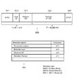
- FIG. 21 illustrates an example of dynamic range conversion definition information.
- the horizontal axis represents the dynamic range before conversion
- the vertical axis represents the dynamic range after conversion.
- the user sets 0 to 40%, 40 to 100%, 100 to 180%, and 180 to 400% of the luminance of the high dynamic range image to 0 to 60%, 60 to 80%, 80 to 90%, and 90 to 100, respectively.
- the second dynamic range image obtained as a result of knee conversion to% is set as a desired converted image.
- knee_function_info SEI 100 is set as pre-conversion position information (input_knee_point [0]) of the first knee position 2101, and 600 is set as post-conversion position information (output_knee_point [0]).
- 250 is set as pre-conversion position information (input_knee_point [1]) of the second knee position 2102 and 800 is set as post-conversion position information (output_knee_point [1]).
- 450 is set as pre-conversion position information (input_knee_point [2]) of the third knee position 2103, and 900 is set as post-conversion position information (output_knee_point [2]).
- knee_function_info SEI As other parameters of knee_function_info SEI, suppose that the input image dynamic range information (input_d_range) is 4000, the input image display display maximum luminance information (input_disp_luminance) is 800 (cd / m 2 ), It is assumed that the compression flag (mapping_flag) is 1.
- the television receiver 13 upon receiving the dynamic range conversion definition information illustrated in FIG. 21, the television receiver 13 recognizes that the luminance output_knee_point at the first to third knee positions is 60%, 80%, and 90%, respectively. To do. Also, the television receiver 13 recognizes from the input image dynamic range information (input_d_range) 605 that the maximum luminance value of the encoding target image is 400%.
- the television receiver 13 connects 0 to 40%, 40-100%, 100-180%, 180-400% of the luminance of the high dynamic range image obtained as a result of decoding by connecting the knee positions in the setting order. Knee conversion into 0 to 60%, 60 to 80%, 80 to 90%, and 90 to 100%, respectively. As a result, the television receiver 13 can convert the high dynamic range image obtained by decoding into a desired second dynamic range image.
- An HDMI source device such as the BD recorder 11 inserts dynamic range conversion definition information into a blanking period (data island section 25 or control section 26) of uncompressed image data, for example, and an HDMI sink such as a television receiver 13 or the like. Can be transmitted to the device.
- the BD recorder 11 transmits the dynamic range conversion definition information to the television receiver 13 via a bidirectional communication path (HEC line) configured using the HPD / Ether + line 35 and the reserve / Ether ⁇ line 37. be able to.
- HEC line bidirectional communication path
- FIG. 7 shows an example of a method for transmitting dynamic range conversion definition information between the BD recorder 11 (HDMI source device) and the television receiver 13 (HDMI sink device). A method for transmitting dynamic range conversion definition information will be described with reference to FIG.
- the information transmission unit 11d of the BD recorder 11 repeatedly transmits the same dynamic range conversion definition information (HDR meta 2) as indicated by reference numeral 704.
- the information transmission unit 11d of the BD recorder 11 repeatedly transmits the same dynamic range conversion definition information (HDR meta 3). To do.
- dynamic range conversion definition information is always transmitted to the transmission path. Therefore, on the television receiver 13 side, if dynamic range conversion definition information is acquired at an arbitrary timing, correct dynamic range conversion processing can be performed.
- HDMI input # 1 the HDMI input
- HDMI input # 1 the HDMI input
- HDMI input # 1 the HDMI input
- HDMI input # 1 the HDMI input
- HDMI input # 1 the HDMI input
- HDMI input # 1 the HDMI input
- HDMI input # 1 the HDMI input
- HDMI input # 1 the HDMI input
- HDMI input # 1 the HDMI input
- HDMI input # 1 the HDMI input
- HDMI input # 1 the HDMI input
- HDMI input # 1 the HDMI input
- HDR meta 2 dynamic range conversion definition information
- the dynamic range conversion definition information (HDR meta 3) is received from the BD recorder 11 at an arbitrary timing, and the image data input from the BD recorder 11 is correctly converted to the dynamic range reverse.
- the original high brightness image (HDR3) can be reproduced as shown by reference numeral 713 after conversion.
- a method of thinning out and transmitting the dynamic range conversion definition information is defined.
- a persistence flag (knee_function_persistence_flag) 603 is provided in the syntax example 600 of “knee_function_info SEI (Supplemental Enhancement Information)” illustrated in FIG. 6, a persistence flag (knee_function_persistence_flag) 603 is provided.
- the persistence flag 603 indicates whether the knee_function_info 200 sent once is still valid or only once. That is, when the high level “1” is set in the persistence flag 603, it indicates that the dynamic range conversion definition information is valid until the stream is switched or the new knee conversion ID 601 is received (described above).
- FIG. 8 shows an example of a method for thinning out and transmitting dynamic range conversion definition information between the BD recorder 11 (HDMI source device) and the television receiver 13 (HDMI sink device).
- BD recorder 11 HDMI source device
- HDMI sink device the television receiver 13
- the corresponding dynamic range conversion definition information (HDR meta 1) is transmitted from the information transmission unit 11d of the BD recorder 11.
- dynamic range conversion definition information (HDR meta 2) corresponding to the image point 803 is sent from the information transmission unit 11d of the BD recorder 11.
- the dynamic range of the uncompressed image data changes at the image point 805, as indicated by reference numeral 806, the dynamic range conversion definition information (HDR) corresponding to the image point 805 is sent from the information transmission unit 11d of the BD recorder 11. Meta 3) is transmitted.
- the dynamic range conversion definition information transmitted at each of the image points 801, 803, and 805 is obtained by repeatedly transmitting the dynamic range conversion definition information by setting the persistence flag 603 to the high level “1” described in FIG. Processing can be omitted.
- the persistence flag 603 of the dynamic range conversion definition information received by the information receiving unit 13d is set to high level “1”
- the dynamic range conversion definition information is converted to the next dynamic range conversion information.
- the definition information is held in the storage unit 13e until it is received.
- HDMI input from the BD recorder 11 (“HDMI input # 1") continues to be fixed. Will be described.
- new dynamic range conversion definition information (HDR meta 1) is received from the BD recorder 11 at the image point 801 by the information receiving unit 13d, the continuation flag is set to high level “1”.
- the storage unit 13e holds the range conversion definition information until it is received.
- the image signal processing circuit 204 and the graphic generation circuit 205 correctly convert the image data input from the BD recorder 11 based on the stored dynamic range conversion definition information (HDR meta 1), and refer to it.
- the original high-intensity image (HDR1) is reproduced.
- FIG. 9 shows an example when the HDMI input switching operation of the television receiver 13 is performed between image points whose dynamic range changes.
- the information transmission unit 11d of the BD recorder 11 corresponds to each image point as indicated by reference numbers 902, 904, and 906.
- the dynamic range conversion definition information HDR meta 1, HDR meta 2, and HDR meta 3 are transmitted.
- the input is switched to the HDMI input from the BD recorder 11 (referred to as “HDMI input # 1”).
- the persistence flag (knee_function_persistence_flag) is set to the high level “1”. Since it is set, it is held in the storage unit 13e until the next dynamic range conversion definition information is received.
- the image signal processing circuit 204 and the graphic generation circuit 205 correctly convert the image data input from the BD recorder 11 based on the dynamic range conversion definition information (HDR meta 1) held in the storage unit 13e. Then, as indicated by reference numeral 911, the original high luminance image (HDR1) is reproduced.
- the persistence flag is set to the high level “1”. Holds until the next dynamic range conversion definition information is received. Also, since the HDMI input remains switched to HDMI input # 1 (BD recorder 11), the television receiver 13 inputs from the BD recorder 11 based on the dynamic range conversion definition information (HDR meta 2) that is held. The image data is correctly subjected to reverse dynamic range conversion, and the original high-brightness image (HDR2) is reproduced as indicated by reference numeral 912.
- the HDMI input is switched from the HDMI input # 1 (BD recorder 11) to the other HDMI input # 2 (STB12) as indicated by reference numeral 913.
- the television receiver 13 While being switched to the HDMI input # 2, the television receiver 13 does not process the image data from the BD recorder 11 (N / A) as indicated by reference numeral 914.
- new dynamic range conversion definition information (HDR meta 3) is transmitted from the information transmission unit 11d of the BD recorder 11, but on the television receiver 13 side, the HDMI is transmitted. This is a period during which signal processing of image data from input # 2 (STB12) is being performed, and since new dynamic range conversion definition information (HDR meta 3) cannot be received, the previous dynamic range conversion definition information HDR2 is retained. Will remain.
- the technology disclosed in this specification introduces a mechanism for controlling transmission of dynamic range conversion definition information from the HDMI sink device to the HDMI source device.
- the television receiver 13 performs a transmission request for dynamic range conversion definition information to the HDMI source device of the input switching destination by a simple method.
- the dynamic range conversion definition information of uncompressed image data can be acquired at a desired timing.
- the television receiver 13 can satisfactorily perform dynamic range conversion of uncompressed image data, and can always display an image with appropriate luminance.
- the television receiver 13 instructs the HDMI sink device to stop transmission of the dynamic range conversion definition information, for example, so that the dynamic range conversion definition information Minimize the transmission of
- FIG. 10 shows an example of a transmission method of dynamic range conversion definition information to which the technology disclosed in this specification is applied.
- the television receiver 13 transmits the transmission request information of the dynamic range conversion definition information to the HDMI source device when the HDMI input is switched.
- the information transmission unit 11d of the BD recorder 11 corresponds to each image point as indicated by reference numbers 1002, 1004, and 1006.
- the dynamic range conversion definition information HDR meta 1, HDR meta 2, and HDR meta 3 are transmitted.
- the television receiver 13 is switched to the HDMI input (referred to as “HDMI input # 1”) from the BD recorder 11, as indicated by reference numeral 1010.
- HDMI input # 1 the HDMI input
- the information receiving unit 13d receives new dynamic range conversion definition information (HDR meta 1) from the BD recorder 11 at the image point 1001
- the persistence flag (knee_function_persistence_flag) is set to the high level “1”. Is stored in the storage unit 13e until the next dynamic range conversion definition information is received.
- the image signal processing circuit 204 and the graphic generation circuit 205 correctly convert the image data input from the BD recorder 11 based on the dynamic range conversion definition information (HDR meta 1) held in the storage unit 13e.
- the original high luminance image (HDR1) is reproduced.
- the information receiving unit 13d receives new dynamic range conversion definition information (HDR meta 2) from the BD recorder 11 at the image point 1003, as indicated by reference numeral 1004, the persistence flag is set to the high level “1”. Therefore, it is held in the storage unit 13e until the next dynamic range conversion definition information is received. Also, since the HDMI input remains switched to HDMI input # 1 (BD recorder 11), the image signal processing circuit 204 and the graphic generation circuit 205 have the dynamic range conversion definition information (HDR meta 2) held in the storage unit 13e. ), The image data input from the BD recorder 11 is correctly subjected to inverse dynamic range conversion, and the original high-brightness image (HDR2) is reproduced as indicated by reference numeral 1012.
- HDR meta 2 new dynamic range conversion definition information
- the HDMI input # 1 (BD recorder 11) to the other HDMI input # 2 (STB 12) on the television receiver 13 side.
- the television receiver 13 While being switched to the HDMI input # 2, the television receiver 13 does not process the image data from the BD recorder 11 (N / A) as indicated by reference numeral 1014.
- new dynamic range conversion definition information (HDR meta 3) is transmitted from the BD recorder 11, but on the television receiver 13 side, HDMI input # 2 (STB 12) is transmitted. ) Is a period during which signal processing of image data is being performed, and new dynamic range conversion definition information (HDR meta 3) cannot be received, so the previous dynamic range conversion definition information HDR2 is retained in the storage unit 13e. It becomes.
- the television receiver 13 sends a transmission request for the dynamic range conversion definition information to the BD recorder 11 that is the HDMI input switching destination.
- the control transmission unit 13c sets the HPD line 35 of the HDMI terminal 13a to a low level “L” for a certain period, and then sets the high level “L”. Control to “H”.
- the control receiver 11c detects the rising edge of the HPD line 35, when it is determined that the transmission control of the dynamic range conversion definition information is performed by the television receiver 13, the reference number 1008 is obtained.
- the same dynamic range conversion definition information (HDR meta 3) as that transmitted at the image point 1015 is transmitted from the information transmission unit 11d.
- dynamic range conversion processing is performed using the dynamic range conversion definition information (HDR meta 3) transmitted again.
- the television receiver 13 controls the HPD line 35 as indicated by reference numeral 1016 by the control transmission unit 13c, so that the dynamic range conversion definition information (HDR meta 3) is set after the HDMI input switching 1015. ), The dynamic range reverse conversion is correctly performed on the input image, and the original high-brightness image (HDR3) can be reproduced well.
- HDR meta 3 the dynamic range conversion definition information
- FIG. 11 shows another example of a dynamic range conversion definition information transmission method to which the technology disclosed in this specification is applied.
- the television receiver 13 transmits the transmission request information of the dynamic range conversion definition information to the HDMI source device when the HDMI input is switched.
- the control transmission unit 13 c of the television receiver 35 transmits the transmission request information of the dynamic range conversion definition information by performing control by controlling the HPD line 35 of the HDMI terminal 13 a.
- the control transmission unit 13c of the television receiver 13 uses a CEC line 34 of the HDMI terminal 13a or a pair of differences using the HPD / Ether + line 35 and the reserve / Ether ⁇ line 37.
- the transmission request control of the dynamic range conversion definition information is performed via a bidirectional communication path (HEC line) composed of a dynamic transmission path.
- HEC line bidirectional communication path
- the information transmission unit 11d of the BD recorder 11 corresponds to each image point as indicated by reference numbers 1102, 1104, and 1106.
- the dynamic range conversion definition information HDR meta 1, HDR meta 2, and HDR meta 3 are transmitted.
- the image point 1101 On the television receiver 13 side, at the time of the image point 1101, as indicated by reference numeral 1110, it is switched to the HDMI input (referred to as “HDMI input # 1”) from the BD recorder 11.
- the persistence flag (knee_function_persistence_flag) is set to the high level “1”. Is stored in the storage unit 13e until the next dynamic range conversion definition information is received.
- the image signal processing circuit 204 and the graphic generation circuit 205 correctly convert the image data input from the BD recorder 11 based on the dynamic range conversion definition information (HDR meta 1) held in the storage unit 13e. Then, as indicated by reference numeral 1111, the original high luminance image (HDR1) is reproduced.
- the HDMI input # 1 (BD recorder 11) to the other HDMI input # 2 (STB 12) on the television receiver 13 side. Assume that input switching is performed. While being switched to the HDMI input # 2, the television receiver 13 does not process the image data from the BD recorder 11 (N / A) as indicated by reference numeral 1114.
- new dynamic range conversion definition information (HDR meta 3) is transmitted from the BD recorder 11.
- the HDMI input # 2 (STB 12) is transmitted. ) Is a period in which signal processing of image data is being performed, and since new dynamic range conversion definition information (HDR meta 3) cannot be received, the previous dynamic range conversion definition information HDR2 is retained in the storage unit 13e. It becomes.
- the television receiver 13 sends a transmission request for the dynamic range conversion definition information to the BD recorder 11 that is the HDMI input switching destination.
- the control transmission unit 13 c performs bidirectional transmission using the CEC line 34 or the HPD / Ether + line 35 and the reserve / Ether ⁇ line 37 of the HDMI terminal 13 a.
- a transmission request command for dynamic range conversion definition information is transmitted via the communication path.
- the BD recorder 11 When the control receiver 11c receives the dynamic range conversion definition information transmission request command via the CEC line 34 or the bidirectional communication path, the BD recorder 11 responds to this by displaying an image point as indicated by reference numeral 1108.
- the same dynamic range conversion definition information (HDR meta 3) as that transmitted in 1015 is transmitted from the information transmitting unit 11d.
- the television receiver 13 can correctly perform dynamic range conversion processing using the dynamic range conversion definition information (HDR meta 3) transmitted again.
- the television receiver 13 acquires appropriate dynamic range conversion definition information (HDR meta 3) after the HDMI input switching 1115 by performing command transmission control as indicated by reference numeral 1116, and The dynamic range reverse conversion is correctly performed on the input image, and the original high brightness image (HDR3) can be reproduced well.
- HDR meta 3 dynamic range conversion definition information
- FIG. 12 shows still another example of a method of transmitting dynamic range conversion definition information to which the technology disclosed in this specification is applied.
- FIG. 7 shows a method of constantly transmitting dynamic range conversion definition information at regular intervals.
- FIG. 12 is configured using the CEC line 34 or the HPD / Ether + line 35 and the reserve / Ether ⁇ line 37 of the HDMI terminal 13a of the television receiver 35 for the purpose of reducing the transmission capacity of the transmission path.
- the transmission control of the dynamic range conversion definition information is performed by transmitting the reception recognition information of the dynamic range conversion definition information via the bidirectional communication path.
- the television receiver 13 side will be described as being fixed to the HDMI input (referred to as “HDMI input # 1”) from the BD recorder 11 as indicated by reference numeral 1210.
- the BD recorder 11 starts from an image point 1201 where the dynamic range of uncompressed image data has changed while transmitting a playback image to the transmission path (HDMI cable 14-1), as indicated by reference numeral 1202. ,
- the repetitive transmission of the corresponding dynamic range conversion definition information (HDR meta 1) is started.
- the image signal processing circuit 204 and the graphic generation circuit 205 correctly convert the image data input from the BD recorder 11 to the dynamic range.
- the inverse transformation is performed to reproduce the original high-intensity image (HDR1) as indicated by reference numeral 1211.
- the control transmission unit 13 c performs the CEC line 34 or HPD / Ether + line of the HDMI terminal 13 a.
- the reception recognition information of the dynamic range conversion definition information is transmitted via a bidirectional communication path (HEC line) between the transmission line 35 and the reserve / ether-line 37.
- the BD recorder 11 repeatedly transmits the corresponding dynamic range conversion definition information (HDR meta 2), starting from an image point 1203 where the dynamic range of the uncompressed image data is changed next, as indicated by reference numeral 1204. To start.
- HDR meta 2 dynamic range conversion definition information
- the image data input from the BD recorder 11 is correctly reverse-converted to the dynamic range, as indicated by reference numeral 1212.
- the original high brightness image (HDR2) is reproduced.
- the control transmission unit 13c transmits the reception recognition information of the dynamic range conversion definition information via the CEC line 34 or the bidirectional communication path (HEC line). To do.
- the reception recognition information of the dynamic range conversion definition information is received by the control reception unit 11c, the transmission of the dynamic range conversion definition information (HDR meta 2) from the information transmission unit 11d is stopped.
- the BD recorder 11 repeats the corresponding dynamic range conversion definition information (HDR meta 3), starting from an image point 1205 where the dynamic range of the uncompressed image data is changed next, as indicated by reference numeral 1206. Start sending.
- HDR meta 3 dynamic range conversion definition information
- the image data input from the BD recorder 11 is correctly reverse-converted to the dynamic range, and is indicated by reference numeral 1213.
- the original high brightness image (HDR3) is reproduced.
- the control transmission unit 13c controls the reception recognition information of the dynamic range conversion definition information via the CEC line 34 or the bidirectional communication path (HEC line). It transmits from the transmission part 13c.
- the reception recognition information of the dynamic range conversion definition information is received by the control reception unit 11c, the transmission of the dynamic range conversion definition information (HDR meta 3) from the information transmission unit 11d is stopped.
- transmission of dynamic range conversion definition information unnecessary on the HDMI source device such as the BD recorder 11 may be omitted by transmission control of dynamic range conversion definition information based on transmission of reception recognition information from the television receiver 13. It is possible to reduce the transmission capacity of the transmission path.
- FIG. 13 shows a data structure example 1300 of a CEC packet transmitted via the CEC line 34 between the HDMI source device and the HDMI sink device.
- the CEC packet 1300 includes a 10-bit CEC header 1310 and variable-length CEC data 1320.
- the control transmission unit 13c on the television receiver 13 side transmits the CEC packet and the control reception unit 11c on the BD recorder 11 side receives the CEC packet.
- the CEC header 1310 includes a 4-bit CEC address (Initiator) 1311, a 4-bit CEC address (Destination) 1312, a 1-bit EOM (End Of Message) 1313, and a 1-bit ACK ( (Acknowledge) 1314.
- CEC data 1320 is composed of a 1-byte control code (Opcode) 1321 and a control data part (Operand) 1322 of up to 14 bytes.
- the control data part (Operand) 1322 of the CEC packet 1300 stores an HDMI CEC command.
- An extension example 1330 of the HDMI CEC command is shown in the lower part of FIG.
- “0xC8” is newly assigned to the CEC control code (Opcode) as a metadata transmission control command, and when dynamic range conversion definition information is requested, an operand is used.
- “0x01” is set in (type).
- “0xC9” is newly assigned as a metadata reception recognition command.
- the television receiver 13 determines that there is no dynamic range conversion definition information when the response data of the response command “Abort” is returned to the transmission control command transmitted to the BD recorder 11, and the dynamic range conversion information is not present. Does not perform conversion processing.
- HEC line As described above, bidirectional communication capable of high-speed LAN communication between the HDMI source device and the HDMI sink device using the pair of differential transmission lines including the HPD / Ether + line 35 and the reserve / Ether ⁇ line 37.
- a path that is, an HEC line can be constructed.
- Transmission control information such as transmission request information of dynamic range conversion definition information and reception recognition information can be transmitted between the HDMI source device and the HDMI sink device via the HEC line.
- the HEC line is high-speed, and it is also possible to transmit dynamic range conversion definition information in synchronization with uncompressed image data.
- FIG. 14 shows a data structure example 1400 of an IP packet transmitted via the HEC line between the HDMI source device and the HDMI sink device.
- the IP packet 1400 includes a 26-octet MAC header 1410 and a variable-length data area 1420.
- the control transmission unit 13c on the television receiver 13 side transmits an IP packet
- the control reception unit 11c on the BD recorder 11 side receives the IP packet.
- the MAC header 1410 includes a 7-octet preamble part 1411, a 1-octet SFD (Start Frame Delimiter) 1412, a 6-octet transmission destination address (Destination MAC address) 1413, and a 6-octet transmission source address.
- (Source MAC address) 1414 a 2-octet TPID (Tag Protocol Identifier) 1415, a 2-octet TCI (Tag Control Information) 1416, and a 2-octet data length format (Len Type) 1417.
- a data area 1420 is composed of a payload part (Payload) 1421 of 42 octets to 1500 octets and an FCS (Frame Check Sequence: FCS) 1422 of 4 octets.
- Payload payload part
- FCS Frarame Check Sequence: FCS
- Transmission control information such as transmission request information and reception recognition information of dynamic range conversion definition information is inserted into the data area 1421 of the payload section 1420.
- 14 shows a data structure example 1430 of transmission control information using IP packets.
- the first byte of the transmission control information 1430 is identification information (id) representing transmission control information, and for example, identification information representing a transmission request command is set.
- the metadata type (metadata type) of the requested transmission control is set. It is also possible to set the metadata of the dynamic range conversion definition information to 0x01 and make a transmission request for metadata other than the dynamic range conversion definition information (for example, gamma definition information) using an IP packet.
- reception recognition command of the dynamic range conversion definition information may be set with identification information (id) different from the transmission request command, or using the same identification information (id) as the transmission control command, A method of setting the type (metadata type) to (for example, 0xFF) may be used.
- FIG. 15 shows a processing procedure for performing transmission control of the dynamic range conversion definition information in the form of a flowchart in the BD recorder 11 as the HDIM source device.
- This processing procedure can be realized, for example, in a form in which the CPU 101 executes a predetermined program code.
- the BD recorder 11 starts this processing when an instruction to start content playback is given by a user operation.
- the BD recorder 11 first determines whether or not there is dynamic range conversion definition information (DR meta) in the uncompressed image data decoded from its own storage medium 11f (step S1501).
- DR meta dynamic range conversion definition information
- step S1501 when there is no dynamic range conversion definition information (No in step S1501), the BD recorder 11 skips subsequent processing and proceeds to step S1507.
- step S1501 when there is dynamic range conversion definition information (Yes in step S1501), the BD recorder 11 determines whether or not the transmission method of the dynamic range conversion definition information is a repetitive transmission method (step S1502).
- the BD recorder 11 when the transmission method of the dynamic range conversion definition information is single (No in step S1502), the BD recorder 11 proceeds to step S1508. Then, the BD recorder 11 transmits the dynamic range conversion definition information in which the persistence flag (knee_function_persistence_flag) is set to the high level “1” from the information transmission unit 11d to the television receiver 13 as the HDMI sink device (step S1508). ), And proceeds to step S1506.
- the BD recorder 11 sets the dynamic range conversion definition information in which the persistence flag (knee_function_persistence_flag) is set to the low level “0”. Information is transmitted from the information transmitting unit 11d to the television receiver 13 (step S1503).
- the BD recorder 11 determines whether or not the reception recognition information (ACK) is received from the television receiver 13 by the control receiver 11c (step S1504).
- the process returns to step S1503, and the BD recorder 11 repeats the transmission of the dynamic range conversion definition information.
- step S1504 When the control receiver 11c receives the reception recognition information from the television receiver 13 (Yes in step S1504), the BD recorder 11 determines that the television receiver 13 has correctly received the dynamic range conversion definition information, and performs dynamic range conversion. The transmission of definition information is stopped (step S1505).
- the BD recorder 11 determines whether or not the transmission request information has been received from the television receiver 13 by the control receiver 11c (step S1506).
- the BD recorder 11 returns to step S1502 and retransmits the dynamic range conversion definition information to the television receiver 13.
- the BD recorder 11 determines whether or not the content reproduction has been stopped by the user's operation. (Step S1507).
- the BD recorder 11 returns to step S1501 and repeats the determination of the presence / absence of new dynamic range conversion definition information.
- the BD recorder 11 immediately ends this processing routine.
- the BD recorder 11 transmits the dynamic range conversion definition information in response to receiving the transmission request information from the television receiver 13, the television receiver 13 side performs dynamic range conversion at a desired timing.
- definition information it is possible to satisfactorily perform dynamic range conversion of uncompressed image data, and to always display an image with appropriate luminance.
- the BD recorder 11 when receiving the reception recognition information from the television receiver 13, the BD recorder 11 can omit the transmission of unnecessary dynamic range conversion definition information, and the transmission capacity of the transmission path can be reduced.
- FIG. 16 shows a processing procedure for performing transmission control of dynamic range conversion definition information in the television receiver 13 as the HDMI sink device in the form of a flowchart.
- the television receiver 13 starts this processing routine in response to detecting the execution of the HDMI input switching. First, the television receiver 13 determines whether or not the input switched by the input switching operation is an HDMI input (step S1601). When the input is not HDMI (No in step S1601), the television receiver 13 immediately ends this processing routine.
- the television receiver 13 sends the transmission request information of the dynamic range conversion definition information to the BD recorder 11 that is the HDMI input, as the control transmission unit 13c. (Step S1602). At this time, the television receiver 13 uses the HPD line 35, the CEC line 34, or the bidirectional communication path (HEC line) configured by the HPD / Ether + line 35 and the reserve / Ether-line 37 as a transmission method of the transmission request. Any one of these is appropriately selected.
- the television receiver 13 waits for reception of dynamic range conversion definition information from the BD recorder 11 for a certain period (step S1603).
- step S1603 When the dynamic range conversion definition information cannot be received from the BD recorder 11 within a certain period of time (No in step S1603), the television receiver 13 determines that dynamic range conversion is unnecessary because it cannot receive the dynamic range conversion definition information. Processing that does not perform dynamic range conversion is performed on the uncompressed image data received from the recorder 11 (step S1606), and this processing routine is immediately terminated.
- the television receiver 13 controls the reception recognition information of the dynamic range conversion definition information. Transmission is performed from the transmission unit 13c to the BD recorder 11 (step S1604).
- the television receiver 13 performs the dynamic range conversion process on the uncompressed image data received from the BD recorder 11 based on the received dynamic range conversion definition information (step S1605), and immediately executes this processing routine. finish.
- the television receiver 13 performs the HDMI input switching, and when performing a new dynamic range conversion process, the television receiver 13 transmits the transmission request information to the HDMI source device that is the input switching destination by a simple method.
- the dynamic range conversion definition information of uncompressed image data can be acquired at a desired timing.
- the television receiver 13 can satisfactorily perform dynamic range conversion of uncompressed image data, and can always display an image with appropriate luminance.
- the television receiver 13 when the television receiver 13 can acquire the dynamic range conversion definition information of the uncompressed image data, the television receiver 13 returns the reception recognition information to return the dynamic range conversion definition information from the BD recorder 11. Transmission of range conversion definition information can be minimized.
- the television receiver 13 transmits the transmission control information of the dynamic range conversion definition information to the BD recorder 11, so that the dynamics of the uncompressed image data can be obtained at a desired timing.
- Range conversion definition information can be acquired, and transmission of unnecessary dynamic range conversion definition information from the BD recorder 11 can be omitted to reduce the transmission capacity of the transmission path.
- FIG. 1 An example of an embodiment (see FIG. 1) comprising an AV system 10 configured by connecting a BD recorder 11 as an HDMI source device and a television receiver 13 as an HDMI sink device via each HDMI cable 14-1. Therefore, although the technology disclosed in this specification has been described, the gist of the technology disclosed in this specification is not limited thereto.
- the television receiver 13 transmits the transmission control information (transmission request information, reception recognition information) of the dynamic range conversion definition information to the STB 12 connected via the HDMI cable 14-2. Dynamic range conversion definition information of uncompressed image data can be acquired at a desired timing, and transmission of unnecessary dynamic range conversion definition information from the STB 12 can be omitted to reduce the transmission capacity of the transmission path. is there.
- the television receiver 13 similarly transmits the transmission control information of the dynamic range conversion definition information according to the IP data structure shown in the lower part of FIG. By transmitting (transmission request information, reception recognition information), it is possible to acquire dynamic range conversion definition information of uncompressed image data at a desired timing, and an unnecessary dynamic range from a content server on the Internet. It is possible to reduce the transmission capacity of the wireless transmission path by omitting transmission of the conversion definition information.
- the television receiver 13 as an HDMI sink device is not an HDMI source device such as the BD recorder 11 or the STB 12, but an HDMI repeater device (AV amplifier or the like: not shown) interposed between the HDMI source device and the HDMI source device.
- an HDMI repeater device AV amplifier or the like: not shown
- FIG. 17 shows a configuration example of a DP system 1700 using a DP interface.
- the illustrated DP system 1700 includes a DP transmission device 1701 and a DP reception device 1707.
- the DP transmitter 1701 includes a DP transmitter 1702
- the DP receiver 1707 includes a DP receiver 1708
- the DP transmitter 1702 and the DP receiver 1708 are connected by a DP cable 1703.
- the DP cable 1703 includes a main link 1704, an AUX channel 1705, and a hot plug detection line 1706.
- the DP transmission device 1701 transmits the packetized data to the DP reception device 1707 via the main link 1704. Further, the DP receiving device 1707 performs connection control and device control with respect to the DP transmitting device 1701 via the AUX channel 1705. Further, the DP receiving device 1701 can detect the connection of the DP transmitting device 1701 by the DC bias potential using the hot plug detection line 1706.
- the main link 1704 consists of one, two, or four double-terminated differential signal pairs (pair lanes), does not have a dedicated clock signal, but instead embeds a clock in the 8B / 10B encoded data stream It is.
- the transmission speed and pixel frequency are independent, and the presence or absence of additional data such as pixel depth, resolution, frame frequency, audio data in the transfer stream, and DRM (Digital Lights Management) information.
- the amount can be adjusted freely. Transmission of uncompressed image data and dynamic range conversion definition information of uncompressed image data is performed using the main link 1704 of the DP interface.
- the DP interface includes a half-duplex bidirectional AUX channel 1705 having a bandwidth of 1 Mbps and a maximum delay of 500 milliseconds.
- Information regarding functions is exchanged between the DP transmission device 1701 and the DP reception device 1701 by bidirectional communication using the AUX channel 1705.
- transmission control information transmission request information, reception recognition information
- the hot plug detection line 1706 is provided to detect that the connection destination has been changed. Similar to the AUX channel 1705 described above, transmission control information (dynamic range conversion definition information of uncompressed image data) ( (Transmission request information, reception recognition information) can also be transmitted.
- the DP system 1700 When the DP receiving device 1707 transmits transmission control information to the DP transmitting device 1701 using the AUX channel 1705 or the hot plug detection line 1706, the DP system 1700 has the same dynamic range as that shown in FIG. 11 or FIG. The transmission control of the conversion definition information can be realized.
- FIG. 18 shows a structural example 1800 of a packet transmitted on the AUX channel 1705 included in the DP interface.
- the packet 1800 includes a header 1810 and a data area 1820.
- the header 1810 includes a synchronization SYNC section 1811, a 4-bit command section (Com) 1812, and a 20-bit transmission destination address (address) 1813.
- a data area 1820 is configured by a payload portion (Payload) 1821 having a length of 8 to 128 bits and a STOP bit 1822.
- Payload payload portion
- the transmission control information (transmission request information, reception recognition information) of the dynamic range conversion definition information is inserted into the payload portion 1821 of the packet 1800.
- 18 shows a data structure example 1830 of transmission control information inserted in the payload portion 1821.
- the seventh bit indicates that when a bit indicating a transmission control request (“Retransmit_request”) is set and set to a high level “1”, the packet 1800 is a transmission control request.
- the 6th to 4th bits indicate the data type (“Metadata_type”) of the transmission control request when the 7th bit is set to the high level “1”.
- 0b001 represents dynamic range conversion definition information
- 0b010 represents gamma definition information.
- 0b011 to 0b111 are reserved ("Reserved") for future expansion.
- the 0th bit indicates that the dynamic range conversion definition information has been received when the bit representing the reception recognition information (“Metadata_recept”) is set and set to the high level “1”.
- FIG. 19 shows a configuration example of an MHL system 1900 using an MHL interface.
- the illustrated MHL system 1900 includes an MHL transmission device 1901 and an MHL reception device 1908.
- the MHL transmission device 1901 includes a TDMS transmission unit 1902 and a storage unit 1903.
- the MHL receiving device 1908 includes a TDMS receiving unit 1909, a storage unit 1910, and an EDID-ROM 1911.
- the TDMS transmission unit 1902 and the TDMS reception unit 1909 are connected by an MHL cable 1904.
- the MHL cable 1904 includes a TMDS channel 1905, a CBUS line or eCBUS line 1906, and a power supply VBUS line 1907.
- the TMDS channel 1905 includes a pair of differential signals, and transmits uncompressed image data and dynamic range conversion definition information of the uncompressed image data. Also, transmission control information (transmission request information, reception recognition information) of dynamic range conversion definition information of uncompressed image data can be transmitted using the CBUS line or eCBUS line 1906.
- the MHL receiving device 1908 transmits transmission control information to the MHL transmitting device 1901 using the CBUS line or the eCBUS line 1906, the dynamic range conversion definition information similar to that shown in FIGS. Transmission control can be realized.
- FIG. 20 shows an example structure 20000 of a packet transmitted on the CBUS channel 1906.
- the packet 2000 includes a SYNC pulse part (SYNC) 2001 for 2 clocks, a 2-bit header part (Header) 2002, a 1-bit control part (CTL) 2003, and an 8-bit control part (CTL) 2003.
- SYNC SYNC pulse part
- Header 2-bit header part
- CTL 1-bit control part
- CTL 8-bit control part
- ACK ACK part
- the transmission control information (transmission request information and reception recognition information) of the dynamic range conversion definition information is inserted into the data portion 2004 of the packet 2000.
- a data structure example 2010 of transmission control information inserted in the data part 2004 is shown.
- the seventh bit indicates that the packet 2000 is a transmission control request when a bit indicating a transmission control request (“Retransmit_request”) is set and set to a high level “1”.
- the 6th to 4th bits indicate the data type (“Metadata_type”) of the transmission control request when the 7th bit is set to the high level “1”.
- 0b001 represents dynamic range conversion definition information
- 0b010 represents gamma definition information.
- 0b011 to 0b111 are reserved ("Reserved") for future expansion.
- the 0th bit indicates that the dynamic range conversion definition information has been received when the bit representing the reception recognition information (“Metadata_recept”) is set and set to the high level “1”.
- the transmission control of the dynamic range conversion definition information by the CBUS line 1906 in the MHL interface will be described in comparison with the HPD 35 line in the HDMI interface.
- the HPD represents a high level “1”.
- HPD represents a low level “0”.
- the transmission control request can be transmitted through the CBUS line 1906.
- an embodiment of an AV system using an HDMI transmission path is shown.
- a baseband digital interface in addition to HDMI, MHL (Mobile High-definition Link), optical fiber interface, DVI (Digital Visual Interface) interface, DP (Display Port) interface, 60 GHz millimeter wave are used.
- MHL Mobile High-definition Link
- DVI Digital Visual Interface
- DP Display Port
- 60 GHz millimeter wave For example, a wireless interface.
- the technique disclosed in this specification can be similarly applied to the case where transmission control information of dynamic range conversion definition information of uncompressed image data is transmitted using these digital interfaces.
- the technology disclosed in this specification can also take the following configurations (1) to (13).
- a communication apparatus comprising: (1-1) The information transmission unit inserts dynamic range conversion definition information of uncompressed image data into a blanking period of uncompressed image data transmitted by the data transmission unit, and transmits the blank range to the external device
- the information transmission unit transmits dynamic range conversion definition information of uncompressed image data to the external device via a bidirectional communication path configured using a predetermined line included in the transmission path.
- the bidirectional communication path includes a pair of differential transmission paths, and at least one of the pair of differential transmission paths has a function of notifying a connection state of the external device.
- the transmission path includes a pair of differential transmission paths, and at least one of the pair of differential transmission paths has a function of notifying a connection state of the external device.
- the control reception unit receives transmission control information from the external device via a line that receives a notification of a connection state of the external device by a DC bias potential of the transmission path.
- the control receiving unit receives transmission control information from the external device via a predetermined control data line included in the transmission path.
- the control reception unit receives transmission control information from the external device via a bidirectional communication path configured using a predetermined line included in the transmission path.
- the communication device according to (1) above. (5) Based on the transmission control information received from the external device by the control receiver, the transmission of the dynamic range conversion definition information from the information transmitter to the external device is controlled.
- (6) a data transmission step of transmitting uncompressed image data to an external device via a transmission path; An information transmission step of transmitting dynamic range conversion definition information of uncompressed image data to the external device via the transmission path; A control reception step of receiving transmission control information of dynamic range conversion definition information from the external device via the transmission path; A transmission control step for controlling transmission of dynamic range conversion definition information to the external device based on the transmission control information received from the external device in the control reception step;
- a communication method comprising: (7) a data transmission unit that transmits uncompressed image data to an external device via a transmission path; An information transmission unit for transmitting dynamic range conversion definition information of uncompressed image data to the external device via the transmission path; A control receiver for receiving transmission control information of dynamic range conversion definition information from the external device via the transmission path; A computer program written in a computer-readable format to make a computer function as (8) a data receiving unit that receives uncompressed image data from an external device via a transmission path; An information receiving unit for receiving dynamic range conversion definition information of uncompressed image data
- the communication device receives the dynamic range conversion definition information of the uncompressed image data from the external device via a bidirectional communication path configured using a predetermined line included in the transmission path.
- the bidirectional communication path includes a pair of differential transmission paths, and at least one of the pair of differential transmission paths has a function of notifying a connection state of the external device.
- the communication device includes a pair of differential transmission paths, and at least one of the pair of differential transmission paths has a function of notifying a connection state of the external device.
- the communication device according to (8) above.
- the control transmission unit Controlling transmission of transmission control information from the control transmitter according to the reception state of the dynamic range conversion definition information in the information receiver.
- the communication device according to (8) above. (8-6)
- the control transmission unit transmits transmission request information requesting transmission of dynamic range conversion definition information to the external device as transmission control information.
- the communication device according to (8) above. (8-7)
- the control transmission unit sends transmission request information for requesting transmission of dynamic range conversion definition information in response to switching to an input from the external device via the transmission path. Send to The communication device according to (8) above.
- the control transmission unit transmits reception recognition information of dynamic range conversion definition information to the external device as transmission control information.
- the control transmission unit transmits the reception recognition information of the dynamic range conversion definition information to the external device in response to the information receiving unit receiving the dynamic range conversion definition information from the external device.
- the communication device according to (8) above. (9) The control transmission unit transmits transmission control information to the external device via a line that receives a notification of a connection state of the external device by a DC bias potential of the transmission path.
- the communication device according to (8) above. (10) The control transmission unit transmits transmission control information to the external device via a predetermined control data line included in the transmission path.
- the communication device according to (8) above. (11) The control transmission unit transmits transmission control information to the external device via a bidirectional communication path configured using a predetermined line included in the transmission path.
- a data receiving step of receiving uncompressed image data from an external device via a transmission path An information receiving step for receiving dynamic range conversion definition information of uncompressed image data from the external device via the transmission path; A control transmission step of transmitting transmission control information of dynamic range conversion definition information to the external device via the transmission path;
- a communication apparatus comprising: (13) a data receiving unit that receives uncompressed image data from an external device via a transmission path; An information receiving unit for receiving dynamic range conversion definition information of uncompressed image data from the external device via the transmission path; A control transmission unit for transmitting transmission control information of dynamic range conversion definition information to the external device via the transmission line;
- Control transmission unit 13i ... Information reception unit 13j ... Storage unit, 13k ... Selection unit, 13m ... Signal processing units 14-1, 14-2 ... HDMI cable 101 ... CPU, 102 ... internal bus, 103 ... flash ROM DESCRIPTION OF SYMBOLS 104 ... SDRAM, 105 ... Remote control receiver, 106 ... Remote control transmitter 107 ... Recording medium control interface, 108 ... BD drive 109 ... HDD, 110 ... MPEG decoder 111 ... Graphic generation circuit, 112 ... Image output terminal 113 ... Audio output terminal , 114 ... Display control unit, 115 ... Panel drive circuit 116 ... Display panel, 117 ... Power supply unit, 118 ...
Landscapes
- Engineering & Computer Science (AREA)
- Multimedia (AREA)
- Signal Processing (AREA)
- Physics & Mathematics (AREA)
- Computer Hardware Design (AREA)
- General Physics & Mathematics (AREA)
- Theoretical Computer Science (AREA)
- Computer Networks & Wireless Communication (AREA)
- Human Computer Interaction (AREA)
- Two-Way Televisions, Distribution Of Moving Picture Or The Like (AREA)
- Controls And Circuits For Display Device (AREA)
- Computer And Data Communications (AREA)
Abstract
Description
伝送路を介して非圧縮画像データを外部機器へ送信するデータ送信部と、
前記伝送路を介して非圧縮画像データのダイナミックレンジ変換定義情報を前記外部機器へ送信する情報送信部と、
前記伝送路を介して前記外部機器からダイナミックレンジ変換定義情報の送信制御情報を受信する制御受信部と、
を具備する通信装置である。 The present application has been made in consideration of the above problems, and the technology according to
A data transmission unit that transmits uncompressed image data to an external device via a transmission path;
An information transmission unit that transmits dynamic range conversion definition information of uncompressed image data to the external device via the transmission path;
A control receiver for receiving transmission control information of dynamic range conversion definition information from the external device via the transmission path;
It is a communication apparatus which comprises.
伝送路を介して非圧縮画像データを外部機器へ送信するデータ送信ステップと、
前記伝送路を介して非圧縮画像データのダイナミックレンジ変換定義情報を前記外部機器へ送信する情報送信ステップと、
前記伝送路を介して前記外部機器からダイナミックレンジ変換定義情報の送信制御情報を受信する制御受信ステップと、
前記制御受信ステップで前記外部機器から受信した送信制御情報に基づいて、前記外部機器へのダイナミックレンジ変換定義情報の送信を制御する送信制御ステップと、
を有する通信方法である。 Further, the technology described in
A data transmission step of transmitting uncompressed image data to an external device via a transmission path;
An information transmission step of transmitting dynamic range conversion definition information of uncompressed image data to the external device via the transmission path;
A control reception step of receiving transmission control information of dynamic range conversion definition information from the external device via the transmission path;
A transmission control step for controlling transmission of dynamic range conversion definition information to the external device based on the transmission control information received from the external device in the control reception step;
Is a communication method.
伝送路を介して非圧縮画像データを外部機器へ送信するデータ送信部、
前記伝送路を介して非圧縮画像データのダイナミックレンジ変換定義情報を前記外部機器へ送信する情報送信部、
前記伝送路を介して前記外部機器からダイナミックレンジ変換定義情報の送信制御情報を受信する制御受信部、
としてコンピューターを機能させるようにコンピューター可読形式で記述されたコンピューター・プログラムである。 Further, the technique described in
A data transmission unit that transmits uncompressed image data to an external device via a transmission path;
An information transmission unit for transmitting dynamic range conversion definition information of uncompressed image data to the external device via the transmission path;
A control receiver for receiving transmission control information of dynamic range conversion definition information from the external device via the transmission path;
As a computer program written in a computer-readable format to make the computer function.
伝送路を介して外部機器から非圧縮画像データを受信するデータ受信部と、
前記伝送路を介して非圧縮画像データのダイナミックレンジ変換定義情報を前記外部機器から受信する情報受信部と、
前記伝送路を介して前記外部機器にダイナミックレンジ変換定義情報の送信制御情報を送信する制御送信部と、
を具備する通信装置である。 Further, the technique described in claim 8 of the present application is:
A data receiver that receives uncompressed image data from an external device via a transmission line;
An information receiving unit for receiving dynamic range conversion definition information of uncompressed image data from the external device via the transmission path;
A control transmitter that transmits transmission control information of dynamic range conversion definition information to the external device via the transmission path;
It is a communication apparatus which comprises.
伝送路を介して外部機器から非圧縮画像データを受信するデータ受信ステップと、
前記伝送路を介して非圧縮画像データのダイナミックレンジ変換定義情報を前記外部機器から受信する情報受信ステップと、
前記伝送路を介して前記外部機器にダイナミックレンジ変換定義情報の送信制御情報を送信する制御送信ステップと、
を具備する通信装置である。 Further, the technique according to claim 12 of the present application is
A data receiving step for receiving uncompressed image data from an external device via a transmission path;
An information receiving step for receiving dynamic range conversion definition information of uncompressed image data from the external device via the transmission path;
A control transmission step of transmitting transmission control information of dynamic range conversion definition information to the external device via the transmission path;
It is a communication apparatus which comprises.
伝送路を介して外部機器から非圧縮画像データを受信するデータ受信部、
前記伝送路を介して非圧縮画像データのダイナミックレンジ変換定義情報を前記外部機器から受信する情報受信部、
前記伝送路を介して前記外部機器にダイナミックレンジ変換定義情報の送信制御情報を送信する制御送信部、
としてコンピューターを機能させるようにコンピューター可読形式で記述されたコンピューター・プログラムである。 In addition, the technique according to claim 13 of the present application is
A data receiving unit that receives uncompressed image data from an external device via a transmission line;
An information receiving unit for receiving dynamic range conversion definition information of uncompressed image data from the external device via the transmission path;
A control transmission unit for transmitting transmission control information of dynamic range conversion definition information to the external device via the transmission line;
As a computer program written in a computer-readable format to make the computer function.
図1には、本明細書で開示する技術を適用したAV(Audio Visual)システム10の機能的構成例を示している。図示のAVシステム10は、HDMIソース機器としてのBD(Blu-ray Disc)レコーダー11及びSTB(Set Top Box)12と、HDMIシンク機器としてのテレビ受信機13とを有している。BDレコーダー11とテレビ受信機13間は、伝送路としてのHDMIケーブル14-1を介して接続されている。また、STB12とテレビ受信機13間は、伝送路としてのHDMIケーブル14-2を介して接続されている。 [System configuration example]
FIG. 1 shows a functional configuration example of an AV (Audio Visual)
図2には、図1に示したAVシステム10における、BDレコーダー11のHDMI送信部11bと、テレビ受信機13のHDMI受信部13bの構成例を示している。なお、図2では、BDレコーダー11とテレビ受信機13間のHDMI送信部11bとHDMI受信部13bの例で構成を説明したが、もう一方のHDMIソース機器及びHDMIシンク機器に組み合わせである、STB12のHDMI送信部12bとHDMI受信部13gの内部構成も同様となる。 [Configuration example of HDMI transmission path]
FIG. 2 shows a configuration example of the
ここで、図3に示したTDMS伝送データの区間について、詳細に説明しておく。HDMIの3つのTMDSチャネル#0、#1、#2で伝送データが伝送されるビデオ・フィールド(Video Field)には、伝送データの種類に応じて、図中で左上がり斜線で塗り潰して示したビデオ・データ区間24(Video Data Period)、左下がり斜線で塗り潰して示したデータ・アイランド区間25(Data Island Period)、及び、ドット柄で塗り潰して示したコントロール区間26(Control Period)の3種類の区間が存在する。 [Configuration example of TMDS channel]
Here, the section of the TDMS transmission data shown in FIG. 3 will be described in detail. The video field (Video Field) in which transmission data is transmitted through the three
図4には、HDMIソース機器としてのBDレコーダー11の構成例を示している。図示のBDレコーダー11は、HDMI端子11aと、HDMI送信部119と、高速バス・インターフェース120を備えている。ここで、HDMI送信部119は、図1に示したHDMI送信部11bに対応した構成である場合と、HDMI送信部11bに制御受信部11cを含めた構成を備える場合がある。 [Configuration example of BD recorder]
FIG. 4 shows a configuration example of the BD recorder 11 as an HDMI source device. The illustrated BD recorder 11 includes an
図5には、HDMIシンク機器としてのテレビ受信機13の構成例を示している。このテレビ受信機13は、HDMI端子13aと13fと、HDMI受信部220と222と、高速バス・インターフェース221と223とを備えている。 [Configuration example of TV receiver]
FIG. 5 shows a configuration example of the television receiver 13 as an HDMI sink device. The television receiver 13 includes
HDMIソース機器から出力される非圧縮画像データは、標準輝度以上のダイナミックレンジを持つ元画像に対してダイナミックレンジ変換を行ない、標準輝度のダイナミックレンジに圧縮された画像データである場合がある。このような場合、HDMIソース機器は、元の非圧縮画像データのダイナミックレンジ変換の処理に使用したダイナミックレンジ変換定義情報を非圧縮データとともに伝送する。一方、HDMIシンク機器は、標準輝度よりも明るい画像を表示可能なディスプレイなどである場合には、ダイナミックレンジ変換定義情報に基づいて受信した画像データに対してダイナミックレンジ逆変換を行なうことで、その性能を活かすような画像表示を行なうことができる。 [Dynamic range conversion definition information]
The uncompressed image data output from the HDMI source device may be image data that has been subjected to dynamic range conversion on an original image having a dynamic range equal to or higher than the standard luminance and compressed to the dynamic range of the standard luminance. In such a case, the HDMI source device transmits the dynamic range conversion definition information used for the dynamic range conversion processing of the original uncompressed image data together with the uncompressed data. On the other hand, when the HDMI sink device is a display capable of displaying an image brighter than the standard luminance, the HDMI sink device performs the inverse dynamic range conversion on the received image data based on the dynamic range conversion definition information. Image display that makes use of performance can be performed.
図7には、BDレコーダー11(HDMIソース機器)とテレビ受信機13(HDMIシンク機器)間でのダイナミックレンジ変換定義情報の伝送方法の一例を示している。図7を参照しながら、ダイナミックレンジ変換定義情報の伝送方法について説明する。 [How to send dynamic range conversion definition information]
FIG. 7 shows an example of a method for transmitting dynamic range conversion definition information between the BD recorder 11 (HDMI source device) and the television receiver 13 (HDMI sink device). A method for transmitting dynamic range conversion definition information will be described with reference to FIG.
CECライン34は、伝送レートが低く非圧縮画像データとは同期がとれないものの、ダイナミックレンジ変換定義情報の送信要求情報や受信認識情報などの送信制御情報をHDMIソース機器とHDMIシンク機器間で伝送することは可能である。 [Data structure example of CEC packet]
Although the
上述したように、HDMIソース機器とHDMIシンク機器の間で、HPD/Ether+ライン35とリザーブ/Ether-ライン37からなる一対の差動伝送路を用いて、高速なLAN通信が可能な双方向通信路、すなわちHECラインを構成することができる。このHECラインを介して、ダイナミックレンジ変換定義情報の送信要求情報や受信認識情報などの送信制御情報をHDMIソース機器とHDMIシンク機器間で伝送することができる。また、HECラインは高速であり、非圧縮画像データと同期してダイナミックレンジ変換定義情報を伝送することも可能である。 [Data structure example of HEC line]
As described above, bidirectional communication capable of high-speed LAN communication between the HDMI source device and the HDMI sink device using the pair of differential transmission lines including the HPD / Ether +
図15には、HDIMソース機器としてのBDレコーダー11においてダイナミックレンジ変換定義情報の送信制御を行なうための処理手順をフローチャートの形式で示している。この処理手順は、例えばCPU101が所定のプログラム・コードを実行するという形態で実現することができる。 [Transmission processing of dynamic range conversion definition information in HDMI source device]
FIG. 15 shows a processing procedure for performing transmission control of the dynamic range conversion definition information in the form of a flowchart in the BD recorder 11 as the HDIM source device. This processing procedure can be realized, for example, in a form in which the
図16には、HDMIシンク機器としてのテレビ受信機13においてダイナミックレンジ変換定義情報の送信制御を行なうための処理手順をフローチャートの形式で示している。 [Transmission processing of dynamic range conversion definition information in HDMI sink device]
FIG. 16 shows a processing procedure for performing transmission control of dynamic range conversion definition information in the television receiver 13 as the HDMI sink device in the form of a flowchart.
HDMIソース機器としてのBDレコーダー11とHDMIシンク機器としてテレビ受信機13が各HDMIケーブル14-1を介して接続されて構成されるAVシステム10からなる実施形態(図1を参照のこと)を例にとって、本明細書で開示する技術について説明してきたが、本明細書で開示する技術の要旨はこれに限定されるものではない。テレビ受信機13は、HDMIケーブル14-2を介して接続されるSTB12に対しても、同様に、ダイナミックレンジ変換定義情報の送信制御情報(送信要求情報、受信認識情報)を送信することによって、所望するタイミングで非圧縮画像データのダイナミックレンジ変換定義情報を取得することができ、且つ、STB12からの不要なダイナミックレンジ変換定義情報の送信を省略して、伝送路の伝送容量の削減が可能である。 [Modification]
An example of an embodiment (see FIG. 1) comprising an
図17には、DPインターフェースを用いたDPシステム1700の構成例を示している。図示のDPシステム1700は、DP送信機器1701とDP受信機器1707で構成される。DP送信機器1701はDP送信部1702を備え、DP受信機器1707はDP受信部1708を備え、DP送信部1702とDP受信部1708とはDPケーブル1703により接続されている。 [DP system structure example]
FIG. 17 shows a configuration example of a DP system 1700 using a DP interface. The illustrated DP system 1700 includes a DP transmission device 1701 and a DP reception device 1707. The DP transmitter 1701 includes a
図18には、DPインターフェースに含まれるAUXチャネル1705上で伝送されるパケットの構造例1800を示している。図18上に示すように、パケット1800は、ヘッダー1810と、データ領域1820で構成される。ヘッダー1810は、同期用のSYNC部1811と、4ビットのコマンド部(Com)1812と、20ビットの伝送先のアドレス(address)1813で構成される。ヘッダー1810に続き、8~128ビット長のペイロード部(Paylaod)1821と、STOPビット1822でデータ領域1820が構成されている。 [Data structure example of AUX channel]
FIG. 18 shows a structural example 1800 of a packet transmitted on the AUX channel 1705 included in the DP interface. As shown in FIG. 18, the
図19には、MHLインターフェースを用いたMHLシステム1900の構成例を示している。図示のMHLシステム1900は、MHL送信機器1901とMHL受信機器1908で構成される。MHL送信機器1901は、TDMS送信部1902と記憶部1903を備えている。また、MHL受信機器1908は、TDMS受信部1909と記憶部1910とEDID-ROM1911を備えている。そして、TDMS送信部1902とTDMS受信部1909とは、MHLケーブル1904より接続されている。 [Example structure of MHL system]
FIG. 19 shows a configuration example of an MHL system 1900 using an MHL interface. The illustrated MHL system 1900 includes an MHL transmission device 1901 and an MHL reception device 1908. The MHL transmission device 1901 includes a
図20には、CBUSチャネル1906上で伝送されるパケットの構造例20000を示している。図20上に示すように、パケット2000は、2クロック分のSYNCパルス部(SYNC)2001と、2ビットのヘッダー部(Header)2002と、1ビットのコントロール部(CTL)2003と、8ビットのデータ部(Data)2004と、1ビットのパリティー部(Parity)2005と、2クロック分のACK部(ACK)2006で構成されている。 [Data structure example of CBUS line]
FIG. 20 shows an example structure 20000 of a packet transmitted on the CBUS channel 1906. As shown in FIG. 20, the
(1)伝送路を介して非圧縮画像データを外部機器へ送信するデータ送信部と、
前記伝送路を介して非圧縮画像データのダイナミックレンジ変換定義情報を前記外部機器へ送信する情報送信部と、
前記伝送路を介して前記外部機器からダイナミックレンジ変換定義情報の送信制御情報を受信する制御受信部と、
を具備する通信装置。
(1-1)前記情報送信部は、非圧縮画像データのダイナミックレンジ変換定義情報を前記データ送信部で送信する非圧縮画像データのブランキング期間に挿入して前記外部機器へ送信する、
上記(1)に記載の通信装置。
(1-2)前記情報送信部は、非圧縮画像データのダイナミックレンジ変換定義情報を、前記伝送路に含まれる所定ラインを用いて構成される双方向通信路を介して、前記外部機器へ送信する、
上記(1)に記載の通信装置。
(1-3)前記双方向通信路は、一対の差動伝送路からなり、前記一対の差動伝送路のうち少なくとも一方は前記外部機器の接続状態の通知機能を備える、
上記(1-2)に記載の通信装置。
(1-4)前記伝送路は、一対の差動伝送路からなり、前記一対の差動伝送路のうち少なくとも一方は前記外部機器の接続状態の通知機能を備える、
上記(1)に記載の通信装置。
(2)前記制御受信部は、前記伝送路の直流バイアス電位によって前記外部機器の接続状態の通知を受信するラインを介して、前記外部機器から送信制御情報を受信する、
上記(1)に記載の通信装置。
(3)前記制御受信部は、前記伝送路に含まれる所定の制御データ・ラインを介して、前記外部機器から送信制御情報を受信する、
上記(1)に記載の通信装置。
(4)前記制御受信部は、前記伝送路に含まれる所定ラインを用いて構成される双方向通信路を介して、前記外部機器から送信制御情報を受信する、
上記(1)に記載の通信装置。
(5)前記制御受信部で前記外部機器から受信した送信制御情報に基づいて、前記情報送信部から前記外部機器へのダイナミックレンジ変換定義情報の送信を制御する、
上記(1)乃至(4)のいずれかに記載の通信装置。
(5-1)前記制御受信部で前記外部機器からダイナミックレンジ変換定義情報の送信要求情報を受信したことに応答して、前記情報送信部からダイナミックレンジ変換定義情報を送信する、
上記(5)に記載の通信装置。
(5-2)前記制御受信部で前記外部機器からダイナミックレンジ変換定義情報の受信認識情報を受信したことに応答して、前記情報送信部からダイナミックレンジ変換定義情報の送信を停止する、
上記(5)に記載の通信装置。
(6)伝送路を介して非圧縮画像データを外部機器へ送信するデータ送信ステップと、
前記伝送路を介して非圧縮画像データのダイナミックレンジ変換定義情報を前記外部機器へ送信する情報送信ステップと、
前記伝送路を介して前記外部機器からダイナミックレンジ変換定義情報の送信制御情報を受信する制御受信ステップと、
前記制御受信ステップで前記外部機器から受信した送信制御情報に基づいて、前記外部機器へのダイナミックレンジ変換定義情報の送信を制御する送信制御ステップと、
を有する通信方法。
(7)伝送路を介して非圧縮画像データを外部機器へ送信するデータ送信部、
前記伝送路を介して非圧縮画像データのダイナミックレンジ変換定義情報を前記外部機器へ送信する情報送信部、
前記伝送路を介して前記外部機器からダイナミックレンジ変換定義情報の送信制御情報を受信する制御受信部、
としてコンピューターを機能させるようにコンピューター可読形式で記述されたコンピューター・プログラム。
(8)伝送路を介して外部機器から非圧縮画像データを受信するデータ受信部と、
前記伝送路を介して非圧縮画像データのダイナミックレンジ変換定義情報を前記外部機器から受信する情報受信部と、
前記伝送路を介して前記外部機器にダイナミックレンジ変換定義情報の送信制御情報を送信する制御送信部と、
を具備する通信装置。
(8-1)前記情報受信部は、前記データ受信部で受信する非圧縮画像データのブランキング期間に挿入されたダイナミックレンジ変換定義情報を受信する、
上記(8)に記載の通信装置。
(8-2)前記情報送信部は、非圧縮画像データのダイナミックレンジ変換定義情報を、前記伝送路に含まれる所定ラインを用いて構成される双方向通信路を介して、前記外部機器から受信する、
上記(8)に記載の通信装置。
(8-3)前記双方向通信路は、一対の差動伝送路からなり、前記一対の差動伝送路のうち少なくとも一方は前記外部機器の接続状態の通知機能を備える、
上記(8-2)に記載の通信装置。
(8-4)前記伝送路は、一対の差動伝送路からなり、前記一対の差動伝送路のうち少なくとも一方は前記外部機器の接続状態の通知機能を備える、
上記(8)に記載の通信装置。
(8-5)前記情報受信部におけるダイナミックレンジ変換定義情報の受信状態に応じて、前記制御送信部からの送信制御情報の送信を制御する、
上記(8)に記載の通信装置。
(8-6)前記制御送信部は、送信制御情報として、ダイナミックレンジ変換定義情報の送信を要求する送信要求情報を前記外部機器へ送信する、
上記(8)に記載の通信装置。
(8-7)前記制御送信部は、前記伝送路を介して前記外部機器からの入力に切換えられたことに応答して、ダイナミックレンジ変換定義情報の送信を要求する送信要求情報を前記外部機器へ送信する、
上記(8)に記載の通信装置。
(8-8)前記制御送信部は、送信制御情報として、ダイナミックレンジ変換定義情報の受信認識情報を前記外部機器へ送信する、
上記(8)に記載の通信装置。
(8-9)前記制御送信部は、前記情報受信部が前記外部機器からダイナミックレンジ変換定義情報を受信したことに応答して、ダイナミックレンジ変換定義情報の受信認識情報を前記外部機器へ送信する、
上記(8)に記載の通信装置。
(9)前記制御送信部は、前記伝送路の直流バイアス電位によって前記外部機器の接続状態の通知を受信するラインを介して、前記外部機器へ送信制御情報を送信する、
上記(8)に記載の通信装置。
(10)前記制御送信部は、前記伝送路に含まれる所定の制御データ・ラインを介して、前記外部機器へ送信制御情報を送信する、
上記(8)に記載の通信装置。
(11)前記制御送信部は、前記伝送路に含まれる所定ラインを用いて構成される双方向通信路を介して、前記外部機器へ送信制御情報を送信する、
上記(8)に記載の通信装置。
(12)伝送路を介して外部機器から非圧縮画像データを受信するデータ受信ステップと、
前記伝送路を介して非圧縮画像データのダイナミックレンジ変換定義情報を前記外部機器から受信する情報受信ステップと、
前記伝送路を介して前記外部機器にダイナミックレンジ変換定義情報の送信制御情報を送信する制御送信ステップと、
を具備する通信装置。
(13)伝送路を介して外部機器から非圧縮画像データを受信するデータ受信部、
前記伝送路を介して非圧縮画像データのダイナミックレンジ変換定義情報を前記外部機器から受信する情報受信部、
前記伝送路を介して前記外部機器にダイナミックレンジ変換定義情報の送信制御情報を送信する制御送信部、
としてコンピューターを機能させるようにコンピューター可読形式で記述されたコンピューター・プログラム。 The technology disclosed in this specification can also take the following configurations (1) to (13).
(1) a data transmission unit that transmits uncompressed image data to an external device via a transmission path;
An information transmission unit that transmits dynamic range conversion definition information of uncompressed image data to the external device via the transmission path;
A control receiver for receiving transmission control information of dynamic range conversion definition information from the external device via the transmission path;
A communication apparatus comprising:
(1-1) The information transmission unit inserts dynamic range conversion definition information of uncompressed image data into a blanking period of uncompressed image data transmitted by the data transmission unit, and transmits the blank range to the external device
The communication device according to (1) above.
(1-2) The information transmission unit transmits dynamic range conversion definition information of uncompressed image data to the external device via a bidirectional communication path configured using a predetermined line included in the transmission path. To
The communication device according to (1) above.
(1-3) The bidirectional communication path includes a pair of differential transmission paths, and at least one of the pair of differential transmission paths has a function of notifying a connection state of the external device.
The communication device according to (1-2) above.
(1-4) The transmission path includes a pair of differential transmission paths, and at least one of the pair of differential transmission paths has a function of notifying a connection state of the external device.
The communication device according to (1) above.
(2) The control reception unit receives transmission control information from the external device via a line that receives a notification of a connection state of the external device by a DC bias potential of the transmission path.
The communication device according to (1) above.
(3) The control receiving unit receives transmission control information from the external device via a predetermined control data line included in the transmission path.
The communication device according to (1) above.
(4) The control reception unit receives transmission control information from the external device via a bidirectional communication path configured using a predetermined line included in the transmission path.
The communication device according to (1) above.
(5) Based on the transmission control information received from the external device by the control receiver, the transmission of the dynamic range conversion definition information from the information transmitter to the external device is controlled.
The communication device according to any one of (1) to (4) above.
(5-1) In response to receiving the transmission request information of the dynamic range conversion definition information from the external device at the control reception unit, the dynamic range conversion definition information is transmitted from the information transmission unit.
The communication device according to (5) above.
(5-2) In response to receiving the reception recognition information of the dynamic range conversion definition information from the external device at the control reception unit, the transmission of the dynamic range conversion definition information from the information transmission unit is stopped.
The communication device according to (5) above.
(6) a data transmission step of transmitting uncompressed image data to an external device via a transmission path;
An information transmission step of transmitting dynamic range conversion definition information of uncompressed image data to the external device via the transmission path;
A control reception step of receiving transmission control information of dynamic range conversion definition information from the external device via the transmission path;
A transmission control step for controlling transmission of dynamic range conversion definition information to the external device based on the transmission control information received from the external device in the control reception step;
A communication method comprising:
(7) a data transmission unit that transmits uncompressed image data to an external device via a transmission path;
An information transmission unit for transmitting dynamic range conversion definition information of uncompressed image data to the external device via the transmission path;
A control receiver for receiving transmission control information of dynamic range conversion definition information from the external device via the transmission path;
A computer program written in a computer-readable format to make a computer function as
(8) a data receiving unit that receives uncompressed image data from an external device via a transmission path;
An information receiving unit for receiving dynamic range conversion definition information of uncompressed image data from the external device via the transmission path;
A control transmitter that transmits transmission control information of dynamic range conversion definition information to the external device via the transmission path;
A communication apparatus comprising:
(8-1) The information receiving unit receives dynamic range conversion definition information inserted in a blanking period of uncompressed image data received by the data receiving unit.
The communication device according to (8) above.
(8-2) The information transmission unit receives the dynamic range conversion definition information of the uncompressed image data from the external device via a bidirectional communication path configured using a predetermined line included in the transmission path. To
The communication device according to (8) above.
(8-3) The bidirectional communication path includes a pair of differential transmission paths, and at least one of the pair of differential transmission paths has a function of notifying a connection state of the external device.
The communication device according to (8-2) above.
(8-4) The transmission path includes a pair of differential transmission paths, and at least one of the pair of differential transmission paths has a function of notifying a connection state of the external device.
The communication device according to (8) above.
(8-5) Controlling transmission of transmission control information from the control transmitter according to the reception state of the dynamic range conversion definition information in the information receiver.
The communication device according to (8) above.
(8-6) The control transmission unit transmits transmission request information requesting transmission of dynamic range conversion definition information to the external device as transmission control information.
The communication device according to (8) above.
(8-7) The control transmission unit sends transmission request information for requesting transmission of dynamic range conversion definition information in response to switching to an input from the external device via the transmission path. Send to
The communication device according to (8) above.
(8-8) The control transmission unit transmits reception recognition information of dynamic range conversion definition information to the external device as transmission control information.
The communication device according to (8) above.
(8-9) The control transmission unit transmits the reception recognition information of the dynamic range conversion definition information to the external device in response to the information receiving unit receiving the dynamic range conversion definition information from the external device. ,
The communication device according to (8) above.
(9) The control transmission unit transmits transmission control information to the external device via a line that receives a notification of a connection state of the external device by a DC bias potential of the transmission path.
The communication device according to (8) above.
(10) The control transmission unit transmits transmission control information to the external device via a predetermined control data line included in the transmission path.
The communication device according to (8) above.
(11) The control transmission unit transmits transmission control information to the external device via a bidirectional communication path configured using a predetermined line included in the transmission path.
The communication device according to (8) above.
(12) a data receiving step of receiving uncompressed image data from an external device via a transmission path;
An information receiving step for receiving dynamic range conversion definition information of uncompressed image data from the external device via the transmission path;
A control transmission step of transmitting transmission control information of dynamic range conversion definition information to the external device via the transmission path;
A communication apparatus comprising:
(13) a data receiving unit that receives uncompressed image data from an external device via a transmission path;
An information receiving unit for receiving dynamic range conversion definition information of uncompressed image data from the external device via the transmission path;
A control transmission unit for transmitting transmission control information of dynamic range conversion definition information to the external device via the transmission line;
A computer program written in a computer-readable format to make a computer function as
11…BDレコーダー
11a…HDMI端子、11b…HDMI送信部、11c…制御受信部
11d…情報送信部、11e…復号部、11f…記憶媒体
12…STB(Set Top Box)
12a…HDMI端子、12b…HDMI送信部、12c…制御受信部
12d…チューナー部、12e…復号部、12f…情報記憶部
12g…情報送信部
13…テレビ受信機
13a…HDMI端子、13b…HDMI受信部、13c…制御送信部
13d…情報受信部、13e…記憶部、13f…HDMI端子
13g…HDMI受信部、13h…制御送信部、13i…情報受信部
13j…記憶部、13k…選択部、13m…信号処理部
14-1、14-2…HDMIケーブル
101…CPU、102…内部バス、103…フラッシュROM
104…SDRAM、105…リモコン受信部、106…リモコン送信機
107…記録媒体制御インターフェース、108…BDドライブ
109…HDD、110…MPEGデコーダー
111…グラフィック生成回路、112…画像出力端子
113…音声出力端子、114…表示制御部、115…パネル駆動回路
116…表示パネル、117…電源部、118…SSD
119…HDMI送信部、120…高速バス・インターフェース
201…アンテナ端子、202…デジタル・チューナー
203…MPEGデコーダー、204…画像信号処理回路
205…グラフィック生成回路、206…パネル駆動回路
207…表示パネル、208…音声信号処理回路、209…音声増幅回路
210…スピーカー、211…内部バス、212…CPU
213…フラッシュROM、214…SDRAM、215…リモコン受信部
216…リモコン送信機、217…ワイヤレス送受信部
218…表示制御部、219…電源部
220…HDMI受信部、221…高速バス・インターフェース
222…HDMI受信部、223…高速バス・インターフェース
1700…DPシステム、1701…DP送信機器、1702…DP送信部
1703…DPケーブル、1704…メインリンク
1705…AUXチャネル、1706…ホットプラグ検知ライン
1707…DP受信機器、1708…DP受信部
1900…MHLシステム
1901…MHL送信機器、1902…TDMS送信部
1903…記憶部、1904…MHLケーブル
1905…TDMSチャネル
1906…CBUSライン又はeCBUSライン
1907…VBUSライン、1908…MHL受信機器
1909…TDMS受信部、1910…記憶部
1911…EDID-ROM DESCRIPTION OF
12a ... HDMI terminal, 12b ... HDMI transmission unit, 12c ... control reception unit 12d ... tuner unit, 12e ... decoding unit, 12f ... information storage unit 12g ... information transmission unit 13 ...
DESCRIPTION OF
DESCRIPTION OF
213: Flash ROM, 214: SDRAM, 215: Remote control receiver 216: Remote control transmitter, 217 ... Wireless transmission /
Claims (13)
- 伝送路を介して非圧縮画像データを外部機器へ送信するデータ送信部と、
前記伝送路を介して非圧縮画像データのダイナミックレンジ変換定義情報を前記外部機器へ送信する情報送信部と、
前記伝送路を介して前記外部機器からダイナミックレンジ変換定義情報の送信制御情報を受信する制御受信部と、
を具備する通信装置。 A data transmission unit that transmits uncompressed image data to an external device via a transmission path;
An information transmission unit that transmits dynamic range conversion definition information of uncompressed image data to the external device via the transmission path;
A control receiver for receiving transmission control information of dynamic range conversion definition information from the external device via the transmission path;
A communication apparatus comprising: - 前記制御受信部は、前記伝送路の直流バイアス電位によって前記外部機器の接続状態の通知を受信するラインを介して、前記外部機器から送信制御情報を受信する、
請求項1に記載の通信装置。 The control reception unit receives transmission control information from the external device via a line that receives a notification of a connection state of the external device by a DC bias potential of the transmission path.
The communication apparatus according to claim 1. - 前記制御受信部は、前記伝送路に含まれる所定の制御データ・ラインを介して、前記外部機器から送信制御情報を受信する、
請求項1に記載の通信装置。 The control receiving unit receives transmission control information from the external device via a predetermined control data line included in the transmission path;
The communication apparatus according to claim 1. - 前記制御受信部は、前記伝送路に含まれる所定ラインを用いて構成される双方向通信路を介して、前記外部機器から送信制御情報を受信する、
請求項1に記載の通信装置。 The control receiving unit receives transmission control information from the external device via a bidirectional communication path configured using a predetermined line included in the transmission path.
The communication apparatus according to claim 1. - 前記制御受信部で前記外部機器から受信した送信制御情報に基づいて、前記情報送信部から前記外部機器へのダイナミックレンジ変換定義情報の送信を制御する、
請求項1乃至4のいずれかに記載の通信装置。 Control transmission of dynamic range conversion definition information from the information transmission unit to the external device based on transmission control information received from the external device by the control reception unit,
The communication apparatus according to claim 1. - 伝送路を介して非圧縮画像データを外部機器へ送信するデータ送信ステップと、
前記伝送路を介して非圧縮画像データのダイナミックレンジ変換定義情報を前記外部機器へ送信する情報送信ステップと、
前記伝送路を介して前記外部機器からダイナミックレンジ変換定義情報の送信制御情報を受信する制御受信ステップと、
前記制御受信ステップで前記外部機器から受信した送信制御情報に基づいて、前記外部機器へのダイナミックレンジ変換定義情報の送信を制御する送信制御ステップと、
を有する通信方法。 A data transmission step of transmitting uncompressed image data to an external device via a transmission path;
An information transmission step of transmitting dynamic range conversion definition information of uncompressed image data to the external device via the transmission path;
A control reception step of receiving transmission control information of dynamic range conversion definition information from the external device via the transmission path;
A transmission control step for controlling transmission of dynamic range conversion definition information to the external device based on the transmission control information received from the external device in the control reception step;
A communication method comprising: - 伝送路を介して非圧縮画像データを外部機器へ送信するデータ送信部、
前記伝送路を介して非圧縮画像データのダイナミックレンジ変換定義情報を前記外部機器へ送信する情報送信部、
前記伝送路を介して前記外部機器からダイナミックレンジ変換定義情報の送信制御情報を受信する制御受信部、
としてコンピューターを機能させるようにコンピューター可読形式で記述されたコンピューター・プログラム。 A data transmission unit that transmits uncompressed image data to an external device via a transmission path;
An information transmission unit for transmitting dynamic range conversion definition information of uncompressed image data to the external device via the transmission path;
A control receiver for receiving transmission control information of dynamic range conversion definition information from the external device via the transmission path;
A computer program written in a computer-readable format to make a computer function as - 伝送路を介して外部機器から非圧縮画像データを受信するデータ受信部と、
前記伝送路を介して非圧縮画像データのダイナミックレンジ変換定義情報を前記外部機器から受信する情報受信部と、
前記伝送路を介して前記外部機器にダイナミックレンジ変換定義情報の送信制御情報を送信する制御送信部と、
を具備する通信装置。 A data receiver that receives uncompressed image data from an external device via a transmission line;
An information receiving unit for receiving dynamic range conversion definition information of uncompressed image data from the external device via the transmission path;
A control transmitter that transmits transmission control information of dynamic range conversion definition information to the external device via the transmission path;
A communication apparatus comprising: - 前記制御送信部は、前記伝送路の直流バイアス電位によって前記外部機器の接続状態の通知を受信するラインを介して、前記外部機器へ送信制御情報を送信する、
請求項8に記載の通信装置。 The control transmission unit transmits transmission control information to the external device via a line that receives a notification of a connection state of the external device by a DC bias potential of the transmission path.
The communication apparatus according to claim 8. - 前記制御送信部は、前記伝送路に含まれる所定の制御データ・ラインを介して、前記外部機器へ送信制御情報を送信する、
請求項8に記載の通信装置。 The control transmission unit transmits transmission control information to the external device via a predetermined control data line included in the transmission path.
The communication apparatus according to claim 8. - 前記制御送信部は、前記伝送路に含まれる所定ラインを用いて構成される双方向通信路を介して、前記外部機器へ送信制御情報を送信する、
請求項8に記載の通信装置。 The control transmission unit transmits transmission control information to the external device via a bidirectional communication path configured using a predetermined line included in the transmission path.
The communication apparatus according to claim 8. - 伝送路を介して外部機器から非圧縮画像データを受信するデータ受信ステップと、
前記伝送路を介して非圧縮画像データのダイナミックレンジ変換定義情報を前記外部機器から受信する情報受信ステップと、
前記伝送路を介して前記外部機器にダイナミックレンジ変換定義情報の送信制御情報を送信する制御送信ステップと、
を具備する通信装置。 A data receiving step for receiving uncompressed image data from an external device via a transmission path;
An information receiving step for receiving dynamic range conversion definition information of uncompressed image data from the external device via the transmission path;
A control transmission step of transmitting transmission control information of dynamic range conversion definition information to the external device via the transmission path;
A communication apparatus comprising: - 伝送路を介して外部機器から非圧縮画像データを受信するデータ受信部、
前記伝送路を介して非圧縮画像データのダイナミックレンジ変換定義情報を前記外部機器から受信する情報受信部、
前記伝送路を介して前記外部機器にダイナミックレンジ変換定義情報の送信制御情報を送信する制御送信部、
としてコンピューターを機能させるようにコンピューター可読形式で記述されたコンピューター・プログラム。 A data receiving unit that receives uncompressed image data from an external device via a transmission line;
An information receiving unit for receiving dynamic range conversion definition information of uncompressed image data from the external device via the transmission path;
A control transmission unit for transmitting transmission control information of dynamic range conversion definition information to the external device via the transmission line;
A computer program written in a computer-readable format to make a computer function as
Priority Applications (7)
| Application Number | Priority Date | Filing Date | Title |
|---|---|---|---|
| EP15792582.7A EP3145206B1 (en) | 2014-05-15 | 2015-02-13 | Communication apparatus, communication method, and computer program |
| CN201580023746.7A CN106464967B (en) | 2014-05-15 | 2015-02-13 | Communication device, communication means and computer readable storage medium |
| JP2016519129A JP6477692B2 (en) | 2014-05-15 | 2015-02-13 | COMMUNICATION DEVICE, COMMUNICATION METHOD, AND COMPUTER PROGRAM |
| RU2016143826A RU2669431C2 (en) | 2014-05-15 | 2015-02-13 | Communication device, method for communication and computer program |
| KR1020167029069A KR20170007261A (en) | 2014-05-15 | 2015-02-13 | Communication apparatus, communication method, and computer program |
| US15/308,869 US10404937B2 (en) | 2014-05-15 | 2015-02-13 | Communication device and communication method |
| US16/512,530 US10999554B2 (en) | 2014-05-15 | 2019-07-16 | Communication device and communication method |
Applications Claiming Priority (2)
| Application Number | Priority Date | Filing Date | Title |
|---|---|---|---|
| JP2014-101704 | 2014-05-15 | ||
| JP2014101704 | 2014-05-15 |
Related Child Applications (2)
| Application Number | Title | Priority Date | Filing Date |
|---|---|---|---|
| US15/308,869 A-371-Of-International US10404937B2 (en) | 2014-05-15 | 2015-02-13 | Communication device and communication method |
| US16/512,530 Continuation US10999554B2 (en) | 2014-05-15 | 2019-07-16 | Communication device and communication method |
Publications (1)
| Publication Number | Publication Date |
|---|---|
| WO2015174108A1 true WO2015174108A1 (en) | 2015-11-19 |
Family
ID=54479655
Family Applications (1)
| Application Number | Title | Priority Date | Filing Date |
|---|---|---|---|
| PCT/JP2015/054037 WO2015174108A1 (en) | 2014-05-15 | 2015-02-13 | Communication apparatus, communication method, and computer program |
Country Status (7)
| Country | Link |
|---|---|
| US (2) | US10404937B2 (en) |
| EP (1) | EP3145206B1 (en) |
| JP (2) | JP6477692B2 (en) |
| KR (1) | KR20170007261A (en) |
| CN (1) | CN106464967B (en) |
| RU (1) | RU2669431C2 (en) |
| WO (1) | WO2015174108A1 (en) |
Cited By (4)
| Publication number | Priority date | Publication date | Assignee | Title |
|---|---|---|---|---|
| US20190075296A1 (en) * | 2014-06-27 | 2019-03-07 | Panasonic Intellectual Property Management Co., Ltd. | Data output apparatus, data output method, and data generation method |
| WO2019140049A1 (en) * | 2018-01-10 | 2019-07-18 | Lumeova, Inc. | Method, devices and system for wireless communication channels fso |
| WO2019208256A1 (en) * | 2018-04-27 | 2019-10-31 | ソニー株式会社 | Information processing device, information processing method, image processing device, image processing method, and program |
| CN111357298A (en) * | 2017-11-22 | 2020-06-30 | 三星电子株式会社 | Apparatus and method for controlling media output level |
Families Citing this family (11)
| Publication number | Priority date | Publication date | Assignee | Title |
|---|---|---|---|---|
| EP3136731B1 (en) * | 2014-04-22 | 2021-12-01 | Sony Group Corporation | Encoding device, encoding method, transmission device, transmission method, reception device, reception method and program |
| JP6834939B2 (en) * | 2015-02-17 | 2021-02-24 | ソニー株式会社 | Transmitter, transmitter, receiver and receiver |
| KR20170134367A (en) * | 2015-04-07 | 2017-12-06 | 소니 주식회사 | Transmitting apparatus, transmitting method, receiving apparatus and receiving method |
| KR102310241B1 (en) | 2015-04-29 | 2021-10-08 | 삼성전자주식회사 | Source device, controlling method thereof, sink device and processing method for improving image quality thereof |
| US20180183899A1 (en) * | 2016-12-23 | 2018-06-28 | Intel Corporation | Transport agnostic display protocol |
| US9986200B1 (en) * | 2017-05-11 | 2018-05-29 | Novatek Microelectronics Corp. | Method and video conversion system of updating video setting |
| US10791003B2 (en) | 2017-10-30 | 2020-09-29 | Intel Corporation | Streaming on diverse transports |
| US11303912B2 (en) * | 2018-04-18 | 2022-04-12 | Qualcomm Incorporated | Decoded picture buffer management and dynamic range adjustment |
| US10470264B1 (en) * | 2018-08-24 | 2019-11-05 | Monolithic Power Systems, Inc. | Smart communication interface for LED matrix control |
| CN111464803B (en) * | 2020-04-16 | 2022-04-12 | 中国长城科技集团股份有限公司 | Display control system |
| CN112422850A (en) * | 2020-11-16 | 2021-02-26 | 飞昂创新科技南通有限公司 | Circuit for carrying out line speed forwarding on low-speed signal of HDMI (high-definition multimedia interface) protocol |
Citations (4)
| Publication number | Priority date | Publication date | Assignee | Title |
|---|---|---|---|---|
| JP2007257641A (en) * | 2006-03-24 | 2007-10-04 | Sharp Corp | Messaging method and system for tone mapping, image reception device, image transmission device, and program |
| WO2012153224A1 (en) * | 2011-05-10 | 2012-11-15 | Koninklijke Philips Electronics N.V. | High dynamic range image signal generation and processing |
| WO2013046095A1 (en) * | 2011-09-27 | 2013-04-04 | Koninklijke Philips Electronics N.V. | Apparatus and method for dynamic range transforming of images |
| WO2013144809A2 (en) * | 2012-03-26 | 2013-10-03 | Koninklijke Philips N.V. | Brightness region-based apparatuses and methods for hdr image encoding and decoding |
Family Cites Families (27)
| Publication number | Priority date | Publication date | Assignee | Title |
|---|---|---|---|---|
| WO1994006247A1 (en) * | 1992-09-08 | 1994-03-17 | Paul Howard Mayeaux | Machine vision camera and video preprocessing system |
| US6118820A (en) * | 1998-01-16 | 2000-09-12 | Sarnoff Corporation | Region-based information compaction as for digital images |
| TWI249630B (en) * | 1999-05-10 | 2006-02-21 | Matsushita Electric Ind Co Ltd | Image display device and method for displaying image |
| JP2006211095A (en) | 2005-01-26 | 2006-08-10 | Matsushita Electric Ind Co Ltd | High luminance compression circuit |
| CN101331771B (en) * | 2006-05-16 | 2010-07-28 | 索尼株式会社 | Communication system, transmission device, reception device, communication method |
| WO2007139534A1 (en) * | 2006-05-25 | 2007-12-06 | Thomson Licensing | Method and system for weighted encoding |
| KR20080046858A (en) * | 2006-11-23 | 2008-05-28 | 엘지전자 주식회사 | A media sink device, a media source device and a controlling method for media sink devices |
| WO2008066840A2 (en) * | 2006-11-27 | 2008-06-05 | Dolby Laboratories Licensing Corporation | Apparatus and methods for boosting dynamic range in digital images |
| JP5029121B2 (en) * | 2007-04-25 | 2012-09-19 | ソニー株式会社 | Data receiving apparatus, data transmitting apparatus, information processing method, and computer program |
| JP2008276067A (en) | 2007-05-02 | 2008-11-13 | Canon Inc | Video display device and its control method |
| JP2009003882A (en) | 2007-06-25 | 2009-01-08 | Toshiba Corp | Data receiver and data transmitting/receiving method |
| US8135230B2 (en) * | 2007-07-30 | 2012-03-13 | Dolby Laboratories Licensing Corporation | Enhancing dynamic ranges of images |
| JP5242111B2 (en) * | 2007-10-02 | 2013-07-24 | 株式会社ソニー・コンピュータエンタテインメント | Transmitting apparatus, image data transmitting method, receiving apparatus, and image display method in receiving apparatus |
| US8175158B2 (en) * | 2008-01-04 | 2012-05-08 | Sharp Laboratories Of America, Inc. | Methods and systems for inter-layer image prediction parameter determination |
| JP5572929B2 (en) * | 2008-03-05 | 2014-08-20 | ソニー株式会社 | Transmitter |
| US8275232B2 (en) * | 2008-06-23 | 2012-09-25 | Mediatek Inc. | Apparatus and method of transmitting / receiving multimedia playback enhancement information, VBI data, or auxiliary data through digital transmission means specified for multimedia data transmission |
| JP2010045584A (en) * | 2008-08-12 | 2010-02-25 | Sony Corp | Solid image correcting apparatus, solid image correcting method, solid image display, solid image reproducing apparatus, solid image presenting system, program, and recording medium |
| JP4645717B2 (en) * | 2008-09-26 | 2011-03-09 | ソニー株式会社 | Interface circuit and video apparatus |
| CN101930719A (en) * | 2009-06-18 | 2010-12-29 | 辉达公司 | Method and system for automatically switching scene mode of display |
| JP5604827B2 (en) * | 2009-08-21 | 2014-10-15 | ソニー株式会社 | Transmitting apparatus, receiving apparatus, program, and communication system |
| US8484077B2 (en) * | 2010-07-21 | 2013-07-09 | Yahoo! Inc. | Using linear and log-linear model combinations for estimating probabilities of events |
| RU2609760C2 (en) * | 2010-09-16 | 2017-02-02 | Конинклейке Филипс Электроникс Н.В. | Improved image encoding apparatus and methods |
| CA2733860A1 (en) * | 2011-03-11 | 2012-09-11 | Calgary Scientific Inc. | Method and system for remotely calibrating display of image data |
| JP5655667B2 (en) * | 2011-03-31 | 2015-01-21 | カシオ計算機株式会社 | Imaging apparatus, imaging control method, image processing apparatus, image processing method, and program |
| JP6053767B2 (en) * | 2011-06-14 | 2016-12-27 | コーニンクレッカ フィリップス エヌ ヴェKoninklijke Philips N.V. | Graphic processing for high dynamic range video |
| US10965974B2 (en) * | 2014-03-17 | 2021-03-30 | Sony Corporation | System, device and method for displaying display-dependent media files |
| WO2015178598A1 (en) * | 2014-05-20 | 2015-11-26 | 엘지전자 주식회사 | Method and apparatus for processing video data for display adaptive image reproduction |
-
2015
- 2015-02-13 CN CN201580023746.7A patent/CN106464967B/en active Active
- 2015-02-13 WO PCT/JP2015/054037 patent/WO2015174108A1/en active Application Filing
- 2015-02-13 JP JP2016519129A patent/JP6477692B2/en active Active
- 2015-02-13 US US15/308,869 patent/US10404937B2/en active Active
- 2015-02-13 KR KR1020167029069A patent/KR20170007261A/en not_active Application Discontinuation
- 2015-02-13 RU RU2016143826A patent/RU2669431C2/en active
- 2015-02-13 EP EP15792582.7A patent/EP3145206B1/en active Active
-
2019
- 2019-02-05 JP JP2019018844A patent/JP6702455B2/en active Active
- 2019-07-16 US US16/512,530 patent/US10999554B2/en active Active
Patent Citations (5)
| Publication number | Priority date | Publication date | Assignee | Title |
|---|---|---|---|---|
| JP2007257641A (en) * | 2006-03-24 | 2007-10-04 | Sharp Corp | Messaging method and system for tone mapping, image reception device, image transmission device, and program |
| WO2012153224A1 (en) * | 2011-05-10 | 2012-11-15 | Koninklijke Philips Electronics N.V. | High dynamic range image signal generation and processing |
| WO2013046095A1 (en) * | 2011-09-27 | 2013-04-04 | Koninklijke Philips Electronics N.V. | Apparatus and method for dynamic range transforming of images |
| WO2013046096A1 (en) * | 2011-09-27 | 2013-04-04 | Koninklijke Philips Electronics N.V. | Apparatus and method for dynamic range transforming of images |
| WO2013144809A2 (en) * | 2012-03-26 | 2013-10-03 | Koninklijke Philips N.V. | Brightness region-based apparatuses and methods for hdr image encoding and decoding |
Cited By (9)
| Publication number | Priority date | Publication date | Assignee | Title |
|---|---|---|---|---|
| US20190075296A1 (en) * | 2014-06-27 | 2019-03-07 | Panasonic Intellectual Property Management Co., Ltd. | Data output apparatus, data output method, and data generation method |
| US10645390B2 (en) * | 2014-06-27 | 2020-05-05 | Panasonic Intellectual Property Management Co., Ltd. | Data output apparatus, data output method, and data generation method |
| US11310507B2 (en) | 2014-06-27 | 2022-04-19 | Panasonic Intellectual Property Management Co., Ltd. | Data output apparatus, data output method, and data generation method |
| US11856200B2 (en) | 2014-06-27 | 2023-12-26 | Panasonic Intellectual Property Management Co., Ltd. | Data output apparatus, data output method, and data generation method |
| CN111357298A (en) * | 2017-11-22 | 2020-06-30 | 三星电子株式会社 | Apparatus and method for controlling media output level |
| WO2019140049A1 (en) * | 2018-01-10 | 2019-07-18 | Lumeova, Inc. | Method, devices and system for wireless communication channels fso |
| WO2019208256A1 (en) * | 2018-04-27 | 2019-10-31 | ソニー株式会社 | Information processing device, information processing method, image processing device, image processing method, and program |
| JPWO2019208256A1 (en) * | 2018-04-27 | 2021-04-30 | ソニー株式会社 | Information processing equipment, information processing methods, image processing equipment, image processing methods, and programs |
| JP7363772B2 (en) | 2018-04-27 | 2023-10-18 | ソニーグループ株式会社 | Information processing device, information processing method, image processing device, image processing method, and program |
Also Published As
| Publication number | Publication date |
|---|---|
| JPWO2015174108A1 (en) | 2017-04-20 |
| JP6702455B2 (en) | 2020-06-03 |
| RU2016143826A (en) | 2018-05-08 |
| EP3145206B1 (en) | 2020-07-22 |
| JP6477692B2 (en) | 2019-03-06 |
| US20170070701A1 (en) | 2017-03-09 |
| US10999554B2 (en) | 2021-05-04 |
| JP2019110547A (en) | 2019-07-04 |
| RU2016143826A3 (en) | 2018-05-08 |
| US10404937B2 (en) | 2019-09-03 |
| RU2669431C2 (en) | 2018-10-12 |
| EP3145206A4 (en) | 2018-01-03 |
| CN106464967B (en) | 2019-11-22 |
| EP3145206A1 (en) | 2017-03-22 |
| KR20170007261A (en) | 2017-01-18 |
| CN106464967A (en) | 2017-02-22 |
| US20190342517A1 (en) | 2019-11-07 |
Similar Documents
| Publication | Publication Date | Title |
|---|---|---|
| JP6702455B2 (en) | Display device, display control method, and computer program | |
| JP2021061602A (en) | Display device | |
| JP5428186B2 (en) | Electronics | |
| JP2008283561A (en) | Communication system, video signal transmission method, transmitter, transmitting method, receiver, and receiving method | |
| JP6551401B2 (en) | Communication apparatus or communication method, and computer program | |
| US10134356B2 (en) | Transmission apparatus, method of transmitting image data with wide color gamut, reception apparatus, method of receiving image data with color gamut | |
| WO2016080233A1 (en) | Transmission device, high dynamic range image data transmission method, receiving device, high dynamic range image data receiving method and program | |
| JP5477506B1 (en) | Transmitting apparatus and information processing method | |
| JP5522332B1 (en) | Receiving apparatus and information processing method | |
| JP5910660B2 (en) | Transmitting apparatus and information processing method | |
| JP5910661B2 (en) | Receiving apparatus and information processing method |
Legal Events
| Date | Code | Title | Description |
|---|---|---|---|
| 121 | Ep: the epo has been informed by wipo that ep was designated in this application |
Ref document number: 15792582 Country of ref document: EP Kind code of ref document: A1 |
|
| ENP | Entry into the national phase |
Ref document number: 2016519129 Country of ref document: JP Kind code of ref document: A |
|
| REEP | Request for entry into the european phase |
Ref document number: 2015792582 Country of ref document: EP |
|
| WWE | Wipo information: entry into national phase |
Ref document number: 2015792582 Country of ref document: EP |
|
| ENP | Entry into the national phase |
Ref document number: 20167029069 Country of ref document: KR Kind code of ref document: A |
|
| WWE | Wipo information: entry into national phase |
Ref document number: 15308869 Country of ref document: US |
|
| ENP | Entry into the national phase |
Ref document number: 2016143826 Country of ref document: RU Kind code of ref document: A |
|
| NENP | Non-entry into the national phase |
Ref country code: DE |