WO2015166828A1 - Damper device - Google Patents
Damper device Download PDFInfo
- Publication number
- WO2015166828A1 WO2015166828A1 PCT/JP2015/061963 JP2015061963W WO2015166828A1 WO 2015166828 A1 WO2015166828 A1 WO 2015166828A1 JP 2015061963 W JP2015061963 W JP 2015061963W WO 2015166828 A1 WO2015166828 A1 WO 2015166828A1
- Authority
- WO
- WIPO (PCT)
- Prior art keywords
- damper device
- spring
- damper
- elastic body
- radial direction
- Prior art date
Links
Images


Classifications
-
- F—MECHANICAL ENGINEERING; LIGHTING; HEATING; WEAPONS; BLASTING
- F16—ENGINEERING ELEMENTS AND UNITS; GENERAL MEASURES FOR PRODUCING AND MAINTAINING EFFECTIVE FUNCTIONING OF MACHINES OR INSTALLATIONS; THERMAL INSULATION IN GENERAL
- F16F—SPRINGS; SHOCK-ABSORBERS; MEANS FOR DAMPING VIBRATION
- F16F15/00—Suppression of vibrations in systems; Means or arrangements for avoiding or reducing out-of-balance forces, e.g. due to motion
- F16F15/10—Suppression of vibrations in rotating systems by making use of members moving with the system
- F16F15/12—Suppression of vibrations in rotating systems by making use of members moving with the system using elastic members or friction-damping members, e.g. between a rotating shaft and a gyratory mass mounted thereon
- F16F15/121—Suppression of vibrations in rotating systems by making use of members moving with the system using elastic members or friction-damping members, e.g. between a rotating shaft and a gyratory mass mounted thereon using springs as elastic members, e.g. metallic springs
- F16F15/123—Wound springs
- F16F15/12353—Combinations of dampers, e.g. with multiple plates, multiple spring sets, i.e. complex configurations
- F16F15/1236—Combinations of dampers, e.g. with multiple plates, multiple spring sets, i.e. complex configurations resulting in a staged spring characteristic, e.g. with multiple intermediate plates
- F16F15/12366—Combinations of dampers, e.g. with multiple plates, multiple spring sets, i.e. complex configurations resulting in a staged spring characteristic, e.g. with multiple intermediate plates acting on multiple sets of springs
- F16F15/12373—Combinations of dampers, e.g. with multiple plates, multiple spring sets, i.e. complex configurations resulting in a staged spring characteristic, e.g. with multiple intermediate plates acting on multiple sets of springs the sets of springs being arranged at substantially the same radius
-
- F—MECHANICAL ENGINEERING; LIGHTING; HEATING; WEAPONS; BLASTING
- F16—ENGINEERING ELEMENTS AND UNITS; GENERAL MEASURES FOR PRODUCING AND MAINTAINING EFFECTIVE FUNCTIONING OF MACHINES OR INSTALLATIONS; THERMAL INSULATION IN GENERAL
- F16F—SPRINGS; SHOCK-ABSORBERS; MEANS FOR DAMPING VIBRATION
- F16F15/00—Suppression of vibrations in systems; Means or arrangements for avoiding or reducing out-of-balance forces, e.g. due to motion
- F16F15/10—Suppression of vibrations in rotating systems by making use of members moving with the system
- F16F15/12—Suppression of vibrations in rotating systems by making use of members moving with the system using elastic members or friction-damping members, e.g. between a rotating shaft and a gyratory mass mounted thereon
- F16F15/121—Suppression of vibrations in rotating systems by making use of members moving with the system using elastic members or friction-damping members, e.g. between a rotating shaft and a gyratory mass mounted thereon using springs as elastic members, e.g. metallic springs
- F16F15/123—Wound springs
- F16F15/12353—Combinations of dampers, e.g. with multiple plates, multiple spring sets, i.e. complex configurations
-
- F—MECHANICAL ENGINEERING; LIGHTING; HEATING; WEAPONS; BLASTING
- F16—ENGINEERING ELEMENTS AND UNITS; GENERAL MEASURES FOR PRODUCING AND MAINTAINING EFFECTIVE FUNCTIONING OF MACHINES OR INSTALLATIONS; THERMAL INSULATION IN GENERAL
- F16D—COUPLINGS FOR TRANSMITTING ROTATION; CLUTCHES; BRAKES
- F16D3/00—Yielding couplings, i.e. with means permitting movement between the connected parts during the drive
- F16D3/02—Yielding couplings, i.e. with means permitting movement between the connected parts during the drive adapted to specific functions
- F16D3/12—Yielding couplings, i.e. with means permitting movement between the connected parts during the drive adapted to specific functions specially adapted for accumulation of energy to absorb shocks or vibration
-
- F—MECHANICAL ENGINEERING; LIGHTING; HEATING; WEAPONS; BLASTING
- F16—ENGINEERING ELEMENTS AND UNITS; GENERAL MEASURES FOR PRODUCING AND MAINTAINING EFFECTIVE FUNCTIONING OF MACHINES OR INSTALLATIONS; THERMAL INSULATION IN GENERAL
- F16F—SPRINGS; SHOCK-ABSORBERS; MEANS FOR DAMPING VIBRATION
- F16F15/00—Suppression of vibrations in systems; Means or arrangements for avoiding or reducing out-of-balance forces, e.g. due to motion
- F16F15/10—Suppression of vibrations in rotating systems by making use of members moving with the system
- F16F15/14—Suppression of vibrations in rotating systems by making use of members moving with the system using masses freely rotating with the system, i.e. uninvolved in transmitting driveline torque, e.g. rotative dynamic dampers
- F16F15/1407—Suppression of vibrations in rotating systems by making use of members moving with the system using masses freely rotating with the system, i.e. uninvolved in transmitting driveline torque, e.g. rotative dynamic dampers the rotation being limited with respect to the driving means
- F16F15/1414—Masses driven by elastic elements
-
- F—MECHANICAL ENGINEERING; LIGHTING; HEATING; WEAPONS; BLASTING
- F16—ENGINEERING ELEMENTS AND UNITS; GENERAL MEASURES FOR PRODUCING AND MAINTAINING EFFECTIVE FUNCTIONING OF MACHINES OR INSTALLATIONS; THERMAL INSULATION IN GENERAL
- F16F—SPRINGS; SHOCK-ABSORBERS; MEANS FOR DAMPING VIBRATION
- F16F15/00—Suppression of vibrations in systems; Means or arrangements for avoiding or reducing out-of-balance forces, e.g. due to motion
- F16F15/10—Suppression of vibrations in rotating systems by making use of members moving with the system
- F16F15/12—Suppression of vibrations in rotating systems by making use of members moving with the system using elastic members or friction-damping members, e.g. between a rotating shaft and a gyratory mass mounted thereon
- F16F15/121—Suppression of vibrations in rotating systems by making use of members moving with the system using elastic members or friction-damping members, e.g. between a rotating shaft and a gyratory mass mounted thereon using springs as elastic members, e.g. metallic springs
- F16F15/1217—Motion-limiting means, e.g. means for locking the spring unit in pre-defined positions
-
- F—MECHANICAL ENGINEERING; LIGHTING; HEATING; WEAPONS; BLASTING
- F16—ENGINEERING ELEMENTS AND UNITS; GENERAL MEASURES FOR PRODUCING AND MAINTAINING EFFECTIVE FUNCTIONING OF MACHINES OR INSTALLATIONS; THERMAL INSULATION IN GENERAL
- F16F—SPRINGS; SHOCK-ABSORBERS; MEANS FOR DAMPING VIBRATION
- F16F15/00—Suppression of vibrations in systems; Means or arrangements for avoiding or reducing out-of-balance forces, e.g. due to motion
- F16F15/10—Suppression of vibrations in rotating systems by making use of members moving with the system
- F16F15/12—Suppression of vibrations in rotating systems by making use of members moving with the system using elastic members or friction-damping members, e.g. between a rotating shaft and a gyratory mass mounted thereon
- F16F15/121—Suppression of vibrations in rotating systems by making use of members moving with the system using elastic members or friction-damping members, e.g. between a rotating shaft and a gyratory mass mounted thereon using springs as elastic members, e.g. metallic springs
- F16F15/123—Wound springs
- F16F15/12313—Wound springs characterised by the dimension or shape of spring-containing windows
-
- F—MECHANICAL ENGINEERING; LIGHTING; HEATING; WEAPONS; BLASTING
- F16—ENGINEERING ELEMENTS AND UNITS; GENERAL MEASURES FOR PRODUCING AND MAINTAINING EFFECTIVE FUNCTIONING OF MACHINES OR INSTALLATIONS; THERMAL INSULATION IN GENERAL
- F16F—SPRINGS; SHOCK-ABSORBERS; MEANS FOR DAMPING VIBRATION
- F16F15/00—Suppression of vibrations in systems; Means or arrangements for avoiding or reducing out-of-balance forces, e.g. due to motion
- F16F15/10—Suppression of vibrations in rotating systems by making use of members moving with the system
- F16F15/12—Suppression of vibrations in rotating systems by making use of members moving with the system using elastic members or friction-damping members, e.g. between a rotating shaft and a gyratory mass mounted thereon
- F16F15/121—Suppression of vibrations in rotating systems by making use of members moving with the system using elastic members or friction-damping members, e.g. between a rotating shaft and a gyratory mass mounted thereon using springs as elastic members, e.g. metallic springs
- F16F15/123—Wound springs
- F16F15/12353—Combinations of dampers, e.g. with multiple plates, multiple spring sets, i.e. complex configurations
- F16F15/1236—Combinations of dampers, e.g. with multiple plates, multiple spring sets, i.e. complex configurations resulting in a staged spring characteristic, e.g. with multiple intermediate plates
- F16F15/12366—Combinations of dampers, e.g. with multiple plates, multiple spring sets, i.e. complex configurations resulting in a staged spring characteristic, e.g. with multiple intermediate plates acting on multiple sets of springs
-
- F—MECHANICAL ENGINEERING; LIGHTING; HEATING; WEAPONS; BLASTING
- F16—ENGINEERING ELEMENTS AND UNITS; GENERAL MEASURES FOR PRODUCING AND MAINTAINING EFFECTIVE FUNCTIONING OF MACHINES OR INSTALLATIONS; THERMAL INSULATION IN GENERAL
- F16H—GEARING
- F16H45/00—Combinations of fluid gearings for conveying rotary motion with couplings or clutches
- F16H45/02—Combinations of fluid gearings for conveying rotary motion with couplings or clutches with mechanical clutches for bridging a fluid gearing of the hydrokinetic type
- F16H2045/0221—Combinations of fluid gearings for conveying rotary motion with couplings or clutches with mechanical clutches for bridging a fluid gearing of the hydrokinetic type with damping means
- F16H2045/0226—Combinations of fluid gearings for conveying rotary motion with couplings or clutches with mechanical clutches for bridging a fluid gearing of the hydrokinetic type with damping means comprising two or more vibration dampers
- F16H2045/0231—Combinations of fluid gearings for conveying rotary motion with couplings or clutches with mechanical clutches for bridging a fluid gearing of the hydrokinetic type with damping means comprising two or more vibration dampers arranged in series
-
- F—MECHANICAL ENGINEERING; LIGHTING; HEATING; WEAPONS; BLASTING
- F16—ENGINEERING ELEMENTS AND UNITS; GENERAL MEASURES FOR PRODUCING AND MAINTAINING EFFECTIVE FUNCTIONING OF MACHINES OR INSTALLATIONS; THERMAL INSULATION IN GENERAL
- F16H—GEARING
- F16H45/00—Combinations of fluid gearings for conveying rotary motion with couplings or clutches
- F16H45/02—Combinations of fluid gearings for conveying rotary motion with couplings or clutches with mechanical clutches for bridging a fluid gearing of the hydrokinetic type
- F16H2045/0221—Combinations of fluid gearings for conveying rotary motion with couplings or clutches with mechanical clutches for bridging a fluid gearing of the hydrokinetic type with damping means
- F16H2045/0263—Combinations of fluid gearings for conveying rotary motion with couplings or clutches with mechanical clutches for bridging a fluid gearing of the hydrokinetic type with damping means the damper comprising a pendulum
-
- F—MECHANICAL ENGINEERING; LIGHTING; HEATING; WEAPONS; BLASTING
- F16—ENGINEERING ELEMENTS AND UNITS; GENERAL MEASURES FOR PRODUCING AND MAINTAINING EFFECTIVE FUNCTIONING OF MACHINES OR INSTALLATIONS; THERMAL INSULATION IN GENERAL
- F16H—GEARING
- F16H45/00—Combinations of fluid gearings for conveying rotary motion with couplings or clutches
- F16H45/02—Combinations of fluid gearings for conveying rotary motion with couplings or clutches with mechanical clutches for bridging a fluid gearing of the hydrokinetic type
Definitions
- the present invention relates to a damper device including a plurality of rotating elements, an elastic body that transmits torque between the plurality of rotating elements, and a dynamic damper.
- an output plate that rotates integrally with the turbine, a first coil spring that elastically connects the piston and output plate of the lockup device in the rotational direction, and relative rotation with respect to the output plate
- An inertia member provided in a possible manner and a second coil spring that is arranged radially inward of the first coil spring and elastically connects the inertia member and the output plate in the rotational direction are known.
- the inertia member has an annular plate member and an inertia member main body fixed to the outer peripheral portion of the plate member by a rivet.
- the output plate has a first output plate and a second output plate that support the plate member of the inertia member in the axial direction, and the inertia is provided by the first fixing portion provided on the inner peripheral portion of the first output plate.
- the plate member of the member is supported in the radial direction.
- the second coil spring is disposed in a window hole formed in the plate member so as to be located radially inward of the inertia member body, and can be elastically deformed by the first output plate and the second output plate. Supported.
- the inertia member and the second coil spring constitute a dynamic damper that imparts antiphase vibrations to the output plate and attenuates vibrations of a predetermined frequency.
- the damper device including the dynamic damper includes a drive plate, a driven plate connected to the turbine, an intermediate member, and a plurality of outer peripheral side torsion springs that elastically connect the drive plate and the intermediate member in the rotational direction.
- a plurality of inner peripheral torsion springs that elastically connect the intermediate member and the driven plate in the rotational direction.
- the dynamic damper is coupled to the intermediate member.
- the damper device includes a float member for causing two outer peripheral side torsion springs to act in series.
- a dynamic damper is connected to a float member for acting two outer peripheral side torsion springs in series, or two inner peripheral side torsion springs are acted on in series. It also describes connecting a dynamic damper to the member.
- the torque between the input element and the output element is considered while considering the element to which the dynamic damper is connected so that the vibration damping effect of the dynamic damper can be further enhanced. It is necessary to appropriately determine the overall rigidity (synthetic spring constant) of the elastic body that transmits Further, in the damper device as described above, the vibration to be damped may not be satisfactorily damped by the dynamic damper due to the hysteresis of the elastic body for torque transmission, that is, the frictional force acting on the elastic body when the load is reduced. is there. Therefore, the hysteresis needs to be taken into account when determining the rigidity of the elastic body for torque transmission.
- the main object of the present invention is to further improve the vibration damping performance of the dynamic damper in the damper device including the dynamic damper.
- the damper device comprises: An input element, a first intermediate element, a second intermediate element, an output element, a plurality of first elastic bodies that transmit torque between the input element and the first intermediate element, and the first intermediate element A plurality of second elastic bodies that transmit torque between the second intermediate element and the second intermediate element, and acts in series with the second elastic body and transmits torque between the second intermediate element and the output element A damper device comprising a plurality of third elastic bodies and a dynamic damper including a mass body and an elastic body for vibration absorption, The dynamic damper is coupled to the first intermediate element;
- the second and third elastic bodies may be disposed between the first intermediate element and the second intermediate element, or the first intermediate element so that movement of the damper device in the radial direction is restricted at both ends.
- 2 is a straight coil spring disposed between the intermediate element and the output element, A gap is formed between the body portions of the second and third elastic bodies and a member disposed on the outer side in the radial direction of the second and third elastic bodies.
- the dynamic damper is connected to the first intermediate element.
- the second elastic body that transmits torque between the first intermediate element and the second intermediate element, and the third elastic body that transmits torque between the second intermediate element and the output element are in series with each other.
- the rigidity of the elastic body transmitting torque between the first intermediate element and the output element, that is, the combined spring constant of the second and third elastic bodies can be further reduced, so that the damper device is in operation.
- the first intermediate element can be easily shaken, and the vibration damping effect of the dynamic damper can be further improved.
- straight coil springs are employed as the second and third elastic bodies.
- the second and third elastic bodies are provided between the first intermediate element and the second intermediate element, or the second intermediate element so that the movement of the damper device in the radial direction is restricted at both ends. And the output element.
- a gap is formed between the body portions of the second and third elastic bodies and the members disposed outside in the radial direction of the second and third elastic bodies.
- the hysteresis of the second and third elastic bodies can be reduced, and it can be satisfactorily suppressed that the vibration damping effect of the dynamic damper is impaired by the hysteresis. Therefore, in this damper device, the vibration damping performance of the dynamic damper can be improved extremely well.
- FIG. 3 is an enlarged view showing a second intermediate element and an output element included in the damper device of FIG. 2.
- FIG. 2 shows the starting apparatus containing the damper apparatus which concerns on other embodiment of this invention.
- FIG. 3 shows the damper apparatus which concerns on other embodiment of this invention.
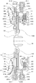
- FIG. 1 is a schematic configuration diagram illustrating a starting device 1 including a damper device 10 according to an embodiment of the present invention
- FIG. 2 is a cross-sectional view illustrating the damper device 10.
- the starting device 1 shown in these drawings is mounted on a vehicle (for example, a front-wheel drive vehicle) provided with an engine (internal combustion engine) as a prime mover.
- a vehicle for example, a front-wheel drive vehicle
- an engine internal combustion engine
- an engine crankshaft (output)
- a front cover 3 as an input member connected to the shaft
- a pump impeller (input side fluid transmission element) 4 fixed to the front cover 3
- a turbine runner (output side fluid transmission element) rotatable coaxially with the pump impeller 4 5)
- a damper hub 7 as an output member connected to the damper device 10 and fixed to the input shaft IS of an automatic transmission (AT) or a continuously variable transmission (CVT); a multi-plate hydraulic clutch;
- a lockup clutch 8 and a dynamic damper 20 connected to the damper device 10 are included.
- the pump impeller 4 has a pump shell (not shown) that is tightly fixed to the front cover 3 and a plurality of pump blades (not shown) disposed on the inner surface of the pump shell.
- the turbine runner 5 includes a turbine shell 50 and a plurality of turbine blades 51 disposed on the inner surface of the turbine shell 50.
- the inner peripheral part of the turbine shell 50 of the turbine runner 5 is fixed to the damper hub 7 via a plurality of rivets.
- the pump impeller 4 and the turbine runner 5 face each other, and a stator 6 (see FIG. 1) that rectifies the flow of hydraulic oil (working fluid) from the turbine runner 5 to the pump impeller 4 is coaxial between the two. Placed in.
- the stator 6 has a plurality of stator blades, and the rotation direction of the stator 6 is set in only one direction by the one-way clutch 60.
- the pump impeller 4, the turbine runner 5, and the stator 6 form a torus (annular flow path) for circulating hydraulic oil, and function as a torque converter (fluid transmission device) having a torque amplification function.
- the stator 6 and the one-way clutch 60 may be omitted, and the pump impeller 4 and the turbine runner 5 may function as a fluid coupling.
- the lockup clutch 8 executes a lockup for connecting the front cover 3 and the damper hub 7, that is, the input shaft IS of the transmission, via the damper device 10 and releases the lockup.
- the lockup clutch 8 includes a lockup piston 80 that is supported by a center piece (not shown) fixed to the front cover 3 so as to be movable in the axial direction, a clutch drum 81, and the front cover 3 so as to face the lockup piston 80.
- the lock-up clutch 8 is positioned on the opposite side of the front cover 3 with respect to the lock-up piston 80, that is, on the damper hub 7 and the damper device 10 side relative to the lock-up piston 80.
- An annular flange member (oil chamber defining member) 85 attached to the center piece, and a plurality of return springs (not shown) disposed between the front cover 3 and the lockup piston 80.
- the lockup piston 80 and the flange member 85 define an engagement oil chamber (not shown), and hydraulic oil (engagement oil pressure) is supplied to the engagement oil chamber from a hydraulic control device (not shown).
- the lockup piston 80 is moved in the axial direction so as to press the first and second friction engagement plates 83 and 84 toward the front cover 3, As a result, the lockup clutch 8 can be engaged (completely engaged or slipped).
- the damper device 10 includes a drive member (input element) 11, a first intermediate member (intermediate element) 12, a second intermediate member (intermediate element) 15, and a driven member (rotating elements).
- Body SP22.
- an arc coil spring made of a metal material wound so as to have an axial center extending in an arc shape when no load is applied is employed as the outer spring SP1.
- the first and second inner springs SP21 and SP22 straight coil springs made of a metal material spirally wound so as to have an axial center extending straight when no load is applied are employed.
- the first and second inner springs SP21 and SP22 having the same specifications (rigidity, that is, spring constant, etc.) are employed. However, the specifications of the first and second inner springs SP21 and SP22 may be different from each other.
- so-called parent-child springs may be employed as the first and second inner springs SP21 and SP22.
- the drive member 11 includes a clutch drum (first member) 81 of the lockup clutch 8 described above and an annular drive plate 91 connected to the clutch drum 81 via a plurality of rivets (fasteners) 89. These are arranged in the outer peripheral region in the fluid transmission chamber 9 defined by the front cover 3 and the pump shell of the pump impeller 4.
- the clutch drum 81 has an annular spring support portion 811 and a plurality (for example, three in this embodiment) of spring contact portions (elastic body contact portions) (not shown).
- the spring support portion 811 includes an outer peripheral portion of the plurality of outer springs SP1, a side portion on the front cover 3 side (engine side) (a right side portion in FIG.
- the plurality of spring contact portions of the clutch drum 81 are arranged on the clutch drum 81 so as to be arranged in the circumferential direction at intervals corresponding to the natural length of the outer spring SP1.
- the drive plate (second member) 91 includes a plurality (for example, three in this embodiment) of spring support portions 911 arranged in the circumferential direction at intervals, and a plurality of (for example, three in the present embodiment).
- the plurality of spring support portions 911 support (guide) the side portions on the turbine runner 5 side of the corresponding outer springs SP1 from the inner peripheral side.
- the plurality of spring contact portions (elastic body contact portions) 913 are arranged on the drive plate 91 so as to be arranged in the circumferential direction at intervals according to the natural length of the outer spring SP1.
- the plurality of outer springs SP1 are supported by the spring support portion 811 and the spring support portion 911 of the drive plate 91 at an interval in the circumferential direction. It arrange
- a plurality of outer springs SP1 are supported from one side (right side in FIG. 2, ie, the front cover 3 side).
- each spring contact portion of the clutch drum 81 is connected to the end between the outer springs SP1 adjacent to each other when the damper device 10 is attached (after the assembly is completed and the damper device 10 is not operating). Abuts against the part.
- each spring abutting portion 913 of the drive plate 91 also abuts against both ends of the outer springs SP1 adjacent to each other when the damper device 10 is attached.
- the first intermediate member 12 is rotatably supported by the annular first plate member 13 disposed on the turbine runner 5 side and the damper hub 7 and is disposed on the front cover 3 side.
- the first intermediate member 12 is first disposed via a plurality of rivets.
- an annular second plate member 14 connected (fixed) to the plate member 13.
- the first plate member 13 constituting the first intermediate member 12 includes a plurality (for example, three in this embodiment) of spring support portions 131 arranged at intervals (equal intervals) in the circumferential direction and intervals in the circumferential direction.
- the plurality of spring support portions 131 support (guide) the side portions on the turbine runner 5 side of the corresponding first and second inner springs SP21 and SP22 (one each) from the outer peripheral side.
- the plurality of spring support portions 132 support (guide) the side portions on the turbine runner 5 side of the corresponding first and second inner springs SP21 and SP22 (one each) from the inner peripheral side.
- the plurality of inner spring contact portions 133 are provided one by one between the spring support portions 131 and 132 adjacent to each other along the circumferential direction.
- the second plate member 14 constituting the first intermediate member 12 includes a short cylindrical supported portion 140 formed by bending an inner peripheral portion so as to extend in the axial direction toward the turbine runner 5, and a circumferential direction.
- a plurality (three in this embodiment) of spring support portions 141 arranged at regular intervals (equal intervals), and the corresponding spring support portions 141 arranged at regular intervals (equal intervals) and the corresponding spring support portions 141 A plurality (three in this embodiment) of spring support portions 142 opposed in the radial direction of the two-plate member 14 and a plurality (for example, three in this embodiment) of inner spring contact portions (elastic body contact portions) 143i, a plurality of (in this embodiment, for example, six) first outer spring contact portions (elastic body contact portions) 143o, a radially inner spring contact portion 143i and a first outer spring.
- a short cylindrical portion 144 extending axially between the grayed abutment 143O.
- the inner peripheral surface of the supported portion 140 of the second plate member 14 is supported by the damper hub 7, and the tip surface of the supported portion 140 abuts against the damper hub 7, thereby restricting movement of the second plate member 14 in the axial direction. Is done.
- the plurality of spring support portions 141 support (guide) the side portions on the front cover 3 side of the corresponding first and second inner springs SP21 and SP22 (one each) from the outer peripheral side.
- the plurality of spring support portions 142 support (guide) the side portions on the front cover 3 side of the corresponding first and second inner springs SP21 and SP22 (one each) from the inner peripheral side.
- the plurality of inner spring contact portions 143i are provided one by one between the spring support portions 141 and 142 adjacent to each other along the circumferential direction.
- the plurality of first outer spring contact portions 143o are arranged so as to form a pair in the circumferential direction with two pairs formed on the outer side in the radial direction and on the front cover 3 side than the plurality of inner spring contact portions 143i.
- the two first outer spring contact portions 143o that are paired with each other face each other with an interval corresponding to the natural length of the outer spring SP1.
- the cylindrical portion 144 (its outer peripheral surface) supports the inner peripheral surface of the drive plate 91 that constitutes the drive member 11. Thereby, the drive member 11 can be rotatably supported (aligned) by the second plate member 14 (first intermediate member 12) supported by the damper hub 7.
- the second intermediate member 15 is configured as a plate-like annular member that surrounds the driven member 16, and is radially inward from the inner peripheral surface thereof, that is, the center of the second intermediate member 15 ( A plurality of (for example, three in this embodiment) spring contact portions (intermediate contact portions) 153 that protrude toward the axial center of the damper device 10 and are arranged at regular intervals (equal intervals) in the circumferential direction.
- the second intermediate member 15 is disposed between the first plate member 13 and the second plate member 14 in the axial direction of the damper device 10 (see FIG. 2), and is rotatable by a drive plate 91 that constitutes the drive member 11. It is supported (alignment). That is, the drive plate 91 includes a plurality of plate support portions 914 that are arranged at intervals in the circumferential direction and extend in the axial direction toward the turbine runner 5. 2 The outer peripheral surface of the intermediate member 15 is supported.
- each spring support portion 131 of the first plate member 13 faces the corresponding spring support portion 141 of the second plate member 14, and the first plate member
- Each of the thirteen spring support portions 132 faces the corresponding spring support portion 142 of the second plate member 14.
- the first inner spring SP21 and the second inner spring SP22 are supported by the first and second plate members 13 and 14 constituting the first intermediate member 12, and are closer to the turbine runner 5 than the plurality of outer springs SP1. They are alternately arranged inside the plurality of outer springs SP1 at intervals in the circumferential direction so as to partially overlap each other as viewed from the radial direction.
- the inner spring contact portions 133 of the first plate member 13 of the first intermediate member 12 and the inner spring contact portions 143 i of the second plate member 14 are different springs. Between the first and second inner springs SP21, SP22 supported by the support portions 131, 132, 141, 142, they abut against both ends. Further, the spring contact portions 153 of the second intermediate member 15 are supported by the same spring support portions 131, 132, 141, 142 and are paired with each other between the first and second inner springs SP21, SP22. It contacts both ends (end faces).
- each first inner spring SP21 abuts on the corresponding inner spring abutting portion 133, 143i of the first intermediate member 12, and the other end of each first inner spring SP21. As shown in FIG. 3, the end face comes into contact with the corresponding spring contact portion 153 of the second intermediate member 15. Further, in the mounted state of the damper device 10, one end (end surface) of each second inner spring SP ⁇ b> 22 comes into contact with a corresponding spring contact portion 153 of the second intermediate member 15 as shown in FIG. The other end of the inner spring SP22 contacts the corresponding inner spring contact portion 133, 143i of the first intermediate member 12.
- each first outer spring contact portion 143o of the second plate member 14 of the first intermediate member 12 is closer to the front cover 3 than the plurality of inner spring contact portions 143i, and the damper. In the mounted state of the device 10, it contacts the end of the corresponding outer spring SP1. That is, in the mounted state of the damper device 10, both end portions of each outer spring SP1 abut against corresponding ones of the two first outer spring abutting portions 143o that form a pair with each other of the second plate member 14.
- the driven member 16 is disposed between the first plate member 13 and the second plate member 14 of the first intermediate member 12 and is fixed to the damper hub 7 via a plurality of rivets. Further, as shown in FIG. 3, the driven members 16 are plurally formed at regular intervals (equally spaced) so as to protrude outward in the radial direction of the damper device 10 (driven member 16). In this embodiment, for example, three spring contact portions (output side contact portions) 163 are provided. In the mounted state of the damper device 10, the spring contact portions 163 of the driven member 16 are both between the first and second inner springs SP21, SP22 supported by different spring support portions 131, 132, 141, 142. Abuts against the end of the.
- each 2nd inner side spring SP22 contact
- the one end of each first inner spring SP21 comes into contact with the corresponding spring contact portion 163 of the driven member 16 (see FIG. 3).
- the driven member 16 is connected to the drive member 11 via the plurality of outer springs SP1, the first intermediate member 12, the plurality of first inner springs SP21, the second intermediate member 15, and the plurality of second inner springs SP22.
- the first and second inner springs SP21 and SP22 that are paired with each other are connected in series between the first intermediate member 12 and the driven member 16 via the spring contact portion 153 of the second intermediate member 15.
- the rigidity of the elastic body that is disposed inside the outer spring SP1 in the radial direction of the damper device 10 and transmits torque between the first intermediate member 12 and the driven member 16, that is, the first and second inner springs.
- the combined spring constant of SP21 and SP22 can be further reduced.
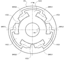
- FIG. 4 is an enlarged view showing the second intermediate member 15 and the driven member 16 of the damper device 10.
- each spring contact portion 153 of the second intermediate member 15 includes a first contact surface 153a that contacts the end surface of the other end of the first inner spring SP21, and a second inner spring SP22.
- a second contact surface 153b that contacts the end surface of the one end.
- the inner peripheral surface 150 of the second intermediate member 15 surrounding the driven member 16 includes a plurality (for example, six in the present embodiment) of radial support surfaces 150c and a plurality (for example, six in the present embodiment). Flank 150e.
- the plurality of radial support surfaces 150c are formed on both sides of each spring contact portion 153 in the circumferential direction of the damper device 10 (second intermediate member 15) so as to form a pair two by two.
- Each radial support surface 150c extends from the base end of the first or second contact surface 153a, 153b so as to be separated from the spring contact portion 153 along the circumferential direction.
- a slight gap is formed between each radial support surface 150c and the corresponding end of the first or second inner spring SP21, SP22.
- Each radial support surface 150c has a corresponding first or second when a centrifugal force acts on the first and second inner springs SP21 and SP22 as the second intermediate member 15 and the driven member 16 rotate.
- the first and second inner springs SP21 and SP22 are supported from the radially outer side by contacting the outer peripheral surface of the end portion of the inner springs SP21 and SP22.
- each radial support surface 150c is in contact with the end surface of the first or second inner spring SP21, SP22 from the outer side in the radial direction, for example, in the range of about one to several turns of the coil when the damper device is attached. It may be formed.
- the plurality of flank surfaces 150e are formed on both sides of the pair of radial support surfaces 150c in the circumferential direction of the damper device 10 (second intermediate member 15) so as to form two pairs.
- each flank 150e is positioned on the outer side in the radial direction of the damper device 10 (second intermediate member 15) with respect to the corresponding radial support surface 150c, and is more than the spring contact portion 153 with respect to the radial support surface 150c. And spaced apart in the circumferential direction.
- a curved surface 150d that protrudes from the radially outer side to the inner side is formed, for example.
- the inner peripheral surface 150 of the second intermediate member 15 includes a plurality (for example, six in the present embodiment) of stopper surfaces 150s and a plurality of (this embodiment) formed between the stopper surfaces 150s adjacent to each other in the circumferential direction.
- three) opposing surfaces 150f are included.
- Each stopper surface 150s extends toward the outer peripheral surface 151 of the second intermediate member 15 from the end of each flank 150e opposite to the radial support surface 150c.
- Each of the opposing surfaces 150f extends in the circumferential direction between the end portions of the stopper surfaces 150s adjacent to each other in the circumferential direction close to the outer peripheral surface 151.
- Each facing surface 150 f faces the outer peripheral surface of the corresponding spring contact portion 163 of the driven member 16 with a gap in the radial direction of the damper device 10.
- Each spring contact portion 163 of the driven member 16 contacts a first contact surface 163a that contacts the end surface of the other end of the second inner spring SP22 and an end surface of the one end of the first inner spring SP21. And a second contact surface 163b. Furthermore, each spring contact portion 163 includes a first radial support portion 163c that protrudes in the circumferential direction outside the first contact surface 163a in the radial direction of the damper device 10 (driven member 16), and a second contact.
- each 1st radial direction support part 163c is the edge part of corresponding 2nd inner side spring SP22, when centrifugal force acts on 2nd inner side spring SP22 with rotation of the 2nd intermediate member 15 or the driven member 16.
- the second inner spring SP22 is supported from the outer side in the radial direction.
- each first radial support portion 163c is formed so as to contact from the outer side in the radial direction within a range of, for example, one to several turns of the coil from the end surface of the second inner spring SP22 when the damper device is attached. Also good. Furthermore, in the mounted state of the damper device 10, each first radial support portion 163c faces the corresponding stopper surface 150s of the second intermediate member 15 with a gap in the circumferential direction.
- each 2nd radial direction support part 163d is the edge part of corresponding 1st inner side spring SP21, when centrifugal force acts on 1st inner side spring SP21 with rotation of the 2nd intermediate member 15 or the driven member 16.
- the first inner spring SP21 is supported from the outer side in the radial direction.
- each second radial support portion 163d is also formed so as to come into contact with the end surface of the first inner spring SP21 from the outer side in the radial direction, for example, in the range of about one to several turns of the coil in the mounted state of the damper device. Also good. Further, in the mounted state of the damper device 10, each second radial support portion 163 d faces the stopper surface 150 s of the second intermediate member 15 corresponding thereto with a gap in the circumferential direction.
- the damper device 10 serves as a rotation restricting stopper that restricts relative rotation between the drive member 11 and the driven member 16, and restricts relative rotation between the drive member 11 and the first intermediate member 12.
- the first inter-element stopper 17 includes a collar mounted on a plurality of rivets that connect the clutch drum 81 and the drive plate 91 constituting the drive member 11, and the second plate member of the first intermediate member 12. 14 formed with a plurality of arc-shaped openings, for example.
- the rivet and the collar that connect the clutch drum 81 and the drive plate 91 do not contact the inner wall surfaces on both sides that define the opening in the corresponding opening of the second plate member 14.
- the second inter-element stopper 18 includes a collar mounted on a plurality of rivets that connect the first and second plate members 13 and 14 constituting the first intermediate member 12, and, for example, a circle formed on the second intermediate member 15. A plurality of notches (openings) extending in an arc shape.
- the rivets and collars connecting the first and second plate members 13, 14 are in contact with the wall surfaces on both sides defining the notch portion in the corresponding notch portion of the second intermediate member 15. Arranged not to.
- the first and second intermediate members 12 and 15 rotate relative to each other, when the collars come into contact with one wall surface of the corresponding notch, the first and second intermediate members 12 and 15 are relative to each other. The rotation and the twist of each first inner spring SP21 are restricted.
- the third inter-element stopper 19 includes a plurality of stopper surfaces 150 s formed on the second intermediate member 15, and first and second radial support portions 163 c and 163 d formed on the spring contact portion 163 of the driven member 16. Consists of. As described above, a gap is formed between each stopper surface 150s of the second intermediate member 15 and the corresponding first or second radial support portion 163c, 163d of the driven member 16 in the mounted state of the damper device 10. Is done. As the second intermediate member 15 and the driven member 16 rotate relative to each other, the stopper surfaces 150s of the second intermediate member 15 and the corresponding first or second radial support portions 163c and 163d of the driven member 16 are brought together. When abutting, the relative rotation between the second intermediate member 15 and the driven member 16 and the twist of each second inner spring SP22 are restricted.
- the relative rotation between the drive member 11 and the first intermediate member 12 and the twist of each outer spring SP1 are restricted by the first inter-element stopper 17, and the first and second intermediate members 12, 15 and the twist of each first inner spring SP21 are restricted, and the third inter-element stopper 19 restricts the relative rotation between the second intermediate member 15 and the driven member 16 and the twist of each second inner spring SP22. Then, the relative rotation between the drive member 11 and the driven member 16 is restricted.
- the first inter-element stopper 17 specificallyations of the drive member 11, the first intermediate member 12 and the outer spring SP1 and the second inter-element stopper 18 (the first intermediate member 12, the second intermediate member 15).
- the specifications of the first inner spring SP21) and the third inter-element stopper 19 are driven by the first inter-element stopper 17. 11 and the first intermediate member 12 before the relative rotation is restricted, the second and third inter-element stoppers 18 and 19 cause the relative rotation of the first and second intermediate members 12 and 15 and the second intermediate member 15 and It is configured (set) so that the relative rotation of the driven member 16 is restricted at the same time.
- the dynamic damper 20 is a plurality of (a straight coil spring or an arc coil spring disposed between the annular mass body 21 and the mass body 21 and the first intermediate member 12 that is the first rotating element of the damper device 10.
- the present embodiment includes, for example, three vibration absorbing springs (vibration absorbing elastic bodies) SPd.
- the “dynamic damper” is a mechanism that attenuates the vibration by adding a vibration in the opposite phase to the vibration body at a frequency (engine speed) that matches the resonance frequency of the vibration body.
- the first intermediate member 12) is configured by connecting a spring (elastic body) and a mass body so as not to be included in the torque transmission path. That is, by adjusting the rigidity of the vibration absorbing spring SPd and the weight of the mass body 21, the dynamic damper 20 can attenuate the vibration of a desired frequency.
- the mass body 21 of the dynamic damper 20 is a fastening member that connects the annular first weight body 23, the annular second weight body 24, and the first and second weight bodies 23, 24.
- the first weight body 23 includes a plurality of (for example, three in this embodiment) first spring support portions 231 arranged at intervals (equal intervals) in the circumferential direction, and a plurality (for example, three in the present embodiment). ) First spring contact portion (elastic body contact portion) 235.
- the plurality of first spring support portions 231 include the outer peripheral portion of the corresponding vibration absorbing spring SPd, the side portion on the turbine runner 5 side (transmission side) (the left side portion in FIG.
- the plurality of first spring contact portions 235 are formed one by one between the first spring support portions 231 adjacent to each other, and the two first spring contact portions 235 adjacent to each other are formed on the first weight body 23. Opposing in the circumferential direction with an interval corresponding to the natural length of the vibration absorbing spring SPd.
- the second weight body 24 is configured as an annular flat plate body having a slightly smaller outer diameter and a larger inner diameter than the first weight body 23, and a plurality of (in the present embodiment, arranged in the circumferential direction).
- three second spring support portions 241 and a plurality (for example, three in this embodiment) of second spring contact portions (elastic body contact portions) 245 are provided.
- the plurality of second spring support portions 241 support (guide) the side portions on the front cover 3 side of the corresponding vibration absorbing springs SPd from the inner peripheral side.
- the plurality of second spring contact portions 245 are formed one by one between the second spring support portions 241 adjacent to each other, and the two second spring contact portions 245 adjacent to each other are formed on the second weight body 24. Opposing in the circumferential direction with an interval corresponding to the natural length of the vibration absorbing spring SPd.
- the plurality of first spring support portions 231 are formed so as to protrude in the axial direction toward the turbine runner 5 from a flat portion including the first spring contact portion 235, and the first spring contact portions A portion including the portion 235 (a portion other than the first spring support portion 231) has a flat plate shape.
- the rivet 25 for connecting the first and second weight bodies 23 and 24 is inserted into the first and second spring contact portions 235 and 245, and the first and second spring support portions 231 and 241 are Opposite to each other and aligned with the rivet 25 in the circumferential direction.
- a plurality of (for example, three in this embodiment) rivets 25 are inserted so as to be positioned concentrically with respect to the pair of first and second spring contact portions 235 and 245 facing each other.
- the first plate member 13 of the first intermediate member 12 to be connected to the dynamic damper 20 includes a short cylindrical portion 134 that extends in the axial direction on the outer side in the radial direction than the plurality of inner spring contact portions 133, and A plurality (for example, six in this embodiment) of outer spring contact parts (elastic body contact parts) 135 arranged to be spaced radially apart from the cylindrical part 134 in the circumferential direction; Have The plurality of outer spring contact portions 135 are formed at equal intervals so as to form a pair (adjacent) two (a pair) on the outer side in the radial direction than the plurality of inner spring contact portions 133 and on the turbine runner 5 side. .
- the two outer spring contact portions 135 that are paired with each other face each other with an interval corresponding to the natural length of the vibration absorbing spring SPd.
- the inner peripheral surface of the second weight body 24 constituting the mass body 21 of the dynamic damper 20 is rotatably supported by the cylindrical portion 134 of the first plate member 13 of the first intermediate member 12.
- the plurality of vibration absorbing springs SPd constituting the dynamic damper 20 are opposed to each other so as to be arranged at regular intervals (equally spaced) between the first and second weight bodies 23 and 24. It is supported by the first spring support portion 231 of the one weight body 23 and the second spring support portion 241 of the second weight body 24.
- the plurality of rivets 25 connecting the first and second weight bodies 23 and 24 are arranged in the circumferential direction between the vibration absorbing springs SPd (first spring support portions 231 and 241) adjacent to each other. It will be.
- the mass body 21 of the dynamic damper 20 and the plurality of vibration absorbing springs SPd are fluid-transmitted so as to be close to the outer periphery of the damper device 10 between the outer peripheral portion of the turbine runner 5 and the outer spring SP1 of the damper device 10.
- the vibration absorbing springs SPd are arranged in the outer peripheral side region in the chamber 9 and overlap with the outer springs SP1 when viewed from the axial direction of the damper device 10.
- the area near the outer periphery of the turbine runner 5 that tends to be a dead space can be effectively used as an arrangement space for the dynamic damper 20, that is, the mass body 21 and the vibration absorbing spring SPd, thereby improving the space efficiency of the entire apparatus. It becomes.
- the vibration absorber spring SPd of the dynamic damper 20 is disposed between the first and second weight bodies 23 and 24 constituting the mass body 21 with a space in the circumferential direction, whereby the mass body 21 and the vibration absorption spring are arranged. It is possible to reduce the space occupied by the dynamic damper 20 by bringing SPd closer to each other.
- the inertia of the mass body 21 can be further increased and the damping performance of the dynamic damper 20 can be further improved.
- the rivet 25 so as to be arranged in the circumferential direction with the vibration absorbing spring SPd between the vibration absorbing springs SPd adjacent to each other, for example, compared to the case where the rivet 25 is arranged on the radial inner side of the vibration absorbing spring SPd.
- the vibration absorbing spring SPd coil diameter
- the inertia of the mass body 21 including the rivet 25 can be further increased.
- the first weight body 23 constituting the mass body 21 has an inner diameter smaller than that of the second weight body 24, the inner peripheral portion of the first weight body 23 is connected to the turbine runner 5 and the Between the first plate member 13 of the first intermediate member 12 and the inner peripheral portion of the second weight body 24, it is located on the radially inner side. Thereby, the weight of the mass body 21 can be further increased.
- each outer spring contact portion 135 of the first plate member 13 of the first intermediate member 12 extends in the radial direction of the damper device 10 in the attached state of the damper device 10 and corresponds to the corresponding vibration absorbing spring SPd.
- the end portion abuts near the center portion of the end portion. That is, in the mounted state of the damper device 10, both end portions of each vibration absorbing spring SPd are in contact with corresponding ones of the two outer spring contact portions 135 that make a pair with each other of the first plate member 13.
- each first spring contact portion 235 of the first weight body 23 constituting the mass body 21 has a diameter of the damper device 10 on the turbine runner 5 side of the outer spring contact portion 135 when the damper device 10 is attached.
- each second spring contact portion 245 of the second weight body 24 constituting the mass body 21 has a diameter of the damper device 10 on the front cover 3 side of the outer spring contact portion 135 in the mounted state of the damper device 10. It extends in the direction and comes into contact with the end of the corresponding vibration absorbing spring SPd. That is, in the mounted state of the damper device 10, both end portions of each vibration absorbing spring SPd abut against corresponding ones of the two first spring abutting portions 235 and 245 of the mass body 21.
- the mass body 21 and the vibration absorbing spring SPd are connected to the first intermediate member 12 of the damper device 10.
- the outer spring contact portion 135 of the first plate member 13 pushes the vicinity of the center of the end of the vibration absorbing spring SPd and the outer spring contact portion 135
- the first spring contact portion 235 of the first weight body 23 and the second spring contact portion 245 of the second weight body 24 that are opposed to each other can substantially push the vicinity of the center of the end portion of the vibration absorbing spring SPd.
- the vibration absorbing spring SPd can be expanded and contracted more appropriately along the axis to reduce the hysteresis, that is, the frictional force acting on the vibration absorbing spring SPd when the load is reduced.
- the dynamic damper 20 is provided with a fourth inter-element stopper 22 that regulates relative rotation between the first plate member 13 of the first intermediate member 12 and the mass body 21.
- the fourth inter-element stopper 22 includes a plurality of rivets 25 that are fastening members that connect the first and second weight bodies 23 and 24, and the outer spring contact portion 135 of the first plate member 13. That is, the plurality of rivets 25 inserted into the pair of first and second spring contact portions 235 and 245 facing each other are adjacent to each other without the vibration absorbing spring SPd in the mounted state of the damper device 10. It arrange
- the fourth inter-element stopper 22 (specifications of the first intermediate member 12, the vibration absorbing spring SPd, and the mass body 21) is the first plate member 13 (before the respective vibration absorbing springs SPd are completely contracted).
- the first intermediate member 12) and the mass body 21 are configured (set) such that relative rotation is restricted.
- the fluctuation of the torque input to the front cover 3 is attenuated (absorbed) by the outer spring SP1 of the damper device 10 acting mainly in series and the first and second inner springs SP21 and SP22. Therefore, in the starting device 1, when the lockup is performed by the lockup clutch 8, it is possible to satisfactorily attenuate (absorb) the fluctuation of the torque input to the front cover 3 by the damper device 10.
- each outer spring contact portion 135 of the first plate member 13 of the first intermediate member 12 responds.
- One end of the vibration absorbing spring SPd is pressed, and the other end of each vibration absorbing spring SPd presses one of the corresponding spring contact portions 235 and 245 of the mass body 21.
- the dynamic damper 20 including the mass body 21 and the plurality of vibration absorbing springs SPd is connected to the first intermediate member 12 of the damper device 10.
- the dynamic damper 20 is connected to the first intermediate member 12.
- a first inner spring SP21 that transmits torque between the first intermediate member 12 and the second intermediate member 15, and a second inner spring SP22 that transmits torque between the second intermediate member 15 and the driven member 16. And act in series with each other.
- the rigidity of the elastic body that transmits torque between the first intermediate member 12 and the driven member 16, that is, the combined spring constant of the first and second inner springs SP21 and SP22 can be further reduced.
- the outer spring SP1 is an arc coil spring, and the drive member 11 supports each outer spring SP1 from the outer side in the radial direction of the damper device 10, the inner side in the radial direction, and one side in the axial direction of the damper device 10.
- the outer spring SP1 is disposed on the radially outer side than the rivet 89 that fastens the clutch drum 81 and the drive plate 91. Accordingly, the length (circumferential length) of the outer spring SP1 is made longer, and the rigidity (synthetic spring constant) of the plurality of outer springs SP1 acting in parallel between the drive member 11 and the first intermediate member 12 is further increased. Can be small. As a result, in the damper device 10, the first intermediate member 12 can be more easily shaken during the operation thereof, and the vibration damping effect of the dynamic damper 20 can be further improved.
- first and second inner springs SP21, SP22 straight coil springs are adopted as the first and second inner springs SP21, SP22, and the first and second inner springs SP21, SP22 are arranged in the radial direction of the damper device 10 at both ends. It arrange
- the damper device 10 when centrifugal force acts on the first and second inner springs SP ⁇ b> 21 and SP ⁇ b> 22 as the first and second intermediate members 15 and the driven member 16 rotate (or from the attached state), The ends of the first and second inner springs SP21 and SP22 are supported from the radially outer side by the radial support surface 150c of the second intermediate member 15. Further, when centrifugal force acts on the first and second inner springs SP21 and SP22 (or since they are in the attached state), the end portion of the second inner spring SP22 is supported by the first radial support portion 163c of the driven member 16. In addition, the end portion of the first inner spring SP21 is supported from the radially outer side by the second radial support portion 163d.
- the second intermediate member 15 is formed with a flank 150e on the outer side in the radial direction with respect to the radial support surface 150c so as to be spaced apart from the spring contact portion 153 in the circumferential direction with respect to the radial support surface 150c. ing.
- the 2nd intermediate member arrange
- a gap is formed between the 15 inner peripheral surfaces 150, that is, the clearance surfaces 150e.
- the stopper surface 150s of the second intermediate member 15 and the first and second radial support portions 163c and 163d of the driven member 16 face each other with an interval in the circumferential direction.
- the straight coil is formed by the radial support surface 150c and the first and second radial support portions 163c and 163d.
- the movement of the first and second inner springs SP21 and SP22, which are springs, to the outside in the radial direction is restricted, and the body portion Bsp of the first and second inner springs SP21 and SP22 is the flank 150e of the second intermediate member 15 or driven.
- the first and second radial support portions 163c and 163d of the member 16 can be prevented from sliding as much as possible.
- the hysteresis of the first and second inner springs SP21 and SP22 that is, the frictional force acting on the first and second inner springs SP21 and SP22 when the load is reduced is reduced, and the vibration damping effect of the dynamic damper 20 is reduced by the hysteresis. It is possible to favorably suppress the damage.
- the vibration damping performance of the dynamic damper 20 is improved extremely well by reducing the rigidity of the outer spring SP1 and the first and second inner springs SP21 and SP22 and reducing the hysteresis as described above. It becomes possible.
- the hysteresis of the first and second inner springs SP21 and SP22 is mainly between the first and second inner springs SP21 and SP22 (elastic body) and the second intermediate member 15 and the driven member 16 (rotating element).
- the output torque output from the driven member 16 (output element) and the input torque decrease when the input torque to the drive member 11 (input element) increases due to the frictional force generated by It can be quantified as the difference that occurs between the actual output torque.
- a gap is formed between the body portion Bsp (axial center) of the first and second inner springs SP21 and SP22 and the flank 150e and the first and second radial support portions 163c and 163d. Configured.
- the hysteresis of the first and second inner springs SP21 and SP22 is maintained while the rotation speed of the drive member 11 is included in the low rotation speed range of the engine including the lockup rotation speed (for example, 1000 to 1500 rpm) of the lockup clutch 8.
- the second intermediate member 15 and the driven member 16 have the first and second members until the rotational speed of the drive member 11 reaches at least 500 to 1000 rpm higher than the lockup speed of the lockup clutch 8.
- a gap may be formed between the body part Bsp of the inner springs SP21 and SP22 and the flank 150e and the first and second radial support parts 163c and 163d.
- the first and second inner springs SP21, SP22 are arranged alternately in the circumferential direction on the radially inner side of the outer spring SP1.
- the centrifugal force acting on the first and second inner springs SP21 and SP22 as the first and second intermediate members 15 and driven member 16 rotate can be further reduced.
- the second intermediate member 15 so as to surround the driven member 16
- the first and second inner springs SP21 and SP22 act in series with each other while suppressing an increase in the axial length of the damper device 10. And the hysteresis of the first and second inner springs SP21 and SP22 can be reduced.
- the stopper surface 150 s of the second intermediate member and the first and second radial support portions 163 c and 163 d of the driven member 16 are opposed to each other with an interval in the circumferential direction when the damper device 10 is attached. Configured to do.
- the body Bsp is prevented from sliding as much as possible to the flank 150e and the first and second radial support portions 163c and 163d.
- the third inter-element stopper 19 that restricts the relative rotation between the second intermediate member 15 and the driven member 16 can be configured.
- the turbine runner 5 is connected (fixed) to the driven member 16 of the damper device 10, so that when the lockup is performed, the starter device 1 is interposed between the front cover 3 and the input shaft IS of the transmission.
- the turbine runner 5 that is not involved in torque transmission functions as a so-called turbine damper. Therefore, when the lockup is executed, the vibration of the driven member 16 and the vibration of the entire damper device 10 can be satisfactorily absorbed by the turbine damper constituted by the turbine runner 5.
- the dynamic damper 20 including the mass body 21 and the vibration absorbing spring SPd is connected to the first intermediate member 12 of the damper device 10.
- the mass body 21 of the dynamic damper 20 includes first and second weight bodies 23 and 24 connected to each other by a rivet (fastening member) 25, and the vibration absorbing spring SPd includes the first and second weight bodies 23. , 24 are spaced apart in the circumferential direction.
- the rivets 25 that connect the first and second weight bodies 23 and 24 are arranged between the adjacent vibration absorbing springs SPd so as to be aligned with the vibration absorbing spring SPd in the circumferential direction.
- the vibration damping spring SPd of the dynamic damper 20 is disposed between the first and second weight bodies 23 and 24 constituting the mass body 21 with an interval in the circumferential direction.
- the space occupied by the dynamic damper 20 can be reduced by bringing the springs SPd closer to each other.
- the area near the outer peripheral portion of the turbine runner 5 that tends to be a dead space is effectively used as the arrangement space for the dynamic damper 20, that is, the mass body 21 and the vibration absorbing spring SPd, thereby improving the space efficiency of the entire device. It becomes possible to make it.
- the vibration absorbing spring SPd (coil diameter) can be increased in diameter and easily reduced in rigidity, and the inertia of the mass body 21 including the rivet 25 can be further increased.
- the damper device 10 including the dynamic damper 20 it is possible to improve the vibration damping performance while suppressing an increase in the size of the entire device.
- the first or second inner springs SP21 and 22 corresponding to the spring contact portion 153 of the second intermediate member 15 and the spring contact portion 163 of the driven member 16 (in the case of a parent-child spring, the outer side or A protrusion as a radial support portion that is fitted inside the end portion of the inner coil spring may be formed.
- the radial support surface 150c of the second intermediate member 15 may be moved radially outward to the same extent as the flank 150e, and the radial support portions 163c and 16d of the driven member 16 may be omitted. Good.
- first and second weight bodies 23, 24 may be divided into a plurality in the circumferential direction, and a plurality of mass bodies 21 may be provided for each vibration absorbing spring SP, for example.
- the second and third inter-element stoppers 18 and 19 have different timings for the relative rotation of the first and second intermediate members 12 and 15 and the relative rotation of the second intermediate member 15 and the driven member 16. You may be comprised so that it may regulate.
- the above-described mass body 21 is replaced with a mass body 21B as a connecting member including the first weight body 23B shown in FIG.
- a dynamic damper 20B including the first and second weight bodies 23B and 24 as the connecting members as mass bodies can be configured.
- the first weight body 23B shown in FIG. 6 has an inner diameter substantially equal to that of the turbine runner 5 (turbine shell 50) and an outer diameter larger than that of the turbine runner 5, and further reduces the inner diameter of the first weight body 23 described above. Is equivalent to
- the first weight body 23B also includes a plurality of first spring support portions 231 and a plurality of first spring contact portions (elastic body contact portions) 235 configured in the same manner as that of the first weight body 23.
- the first weight body 23 ⁇ / b> B is disposed between the turbine runner 5 and the first plate member 13 of the first intermediate member 12, and an inner peripheral portion of the first weight body 23 ⁇ / b> B is coupled with an inner peripheral portion of the turbine shell 50 via a rivet. It is fixed to the hub 52. Further, the turbine hub 52 is rotatably supported by the damper hub 7 as shown in the figure.
- the vibration absorbing springs SPd are formed by the plurality of rivets 25 that are fastening members for connecting the first and second weight bodies 23B, 24 and the outer spring contact portion 135 of the first plate member 13.
- a third inter-element stopper is configured to restrict the relative rotation of the two before completely contracting.
- the damper device transmits torque between the input element, the first intermediate element, the second intermediate element, the output element, and the input element and the first intermediate element.
- a damper device comprising a plurality of third elastic bodies that transmit torque between an element and the output element, and a dynamic damper that includes a mass body and a vibration-absorbing elastic body, wherein the dynamic damper comprises the first intermediate
- the second and third elastic bodies are connected to an element, and the second intermediate element and the second intermediate element are arranged between the first intermediate element and the second intermediate element so that movement of the damper device in the radial direction is restricted at both ends.
- the second intermediate point And a straight coil spring disposed between the output element and the body of the second and third elastic bodies, and a member disposed on the outer side in the radial direction of the second and third elastic bodies;
- a gap is
- the dynamic damper is connected to the first intermediate element.
- the second elastic body that transmits torque between the first intermediate element and the second intermediate element, and the third elastic body that transmits torque between the second intermediate element and the output element are in series with each other.
- the rigidity of the elastic body transmitting torque between the first intermediate element and the output element, that is, the combined spring constant of the second and third elastic bodies can be further reduced, so that the damper device is in operation.
- the first intermediate element can be easily shaken, and the vibration damping effect of the dynamic damper can be further improved.
- straight coil springs are employed as the second and third elastic bodies.
- the second and third elastic bodies are provided between the first intermediate element and the second intermediate element, or the second intermediate element so that the movement of the damper device in the radial direction is restricted at both ends. And the output element.
- a gap is formed between the body portions of the second and third elastic bodies and the members disposed outside in the radial direction of the second and third elastic bodies.
- the hysteresis of the second and third elastic bodies can be reduced, and it can be satisfactorily suppressed that the vibration damping effect of the dynamic damper is impaired by the hysteresis. Therefore, in this damper device, the vibration damping performance of the dynamic damper can be improved extremely well.
- the second and third elastic bodies may be arranged inside the first elastic body in the radial direction so as to be alternately arranged in the circumferential direction of the damper device.
- the first elastic body may be an arc coil spring, and the input element supports the first elastic body at least from the outside in the radial direction and from one side in the axial direction of the damper device.
- One member may be included.
- the length (circumferential length) of the first elastic body is made longer, and the rigidity (synthetic spring constant) of the plurality of first elastic bodies acting in parallel between the input element and the first intermediate element is further increased. Since it can be made small, the first intermediate element can be more easily shaken during operation of the damper device.
- the input element is connected to the first member via a first member that supports at least an outer peripheral portion and the one side portion of the first elastic body, and a plurality of fasteners, and A second member that supports at least an inner peripheral side of the side opposite to the one side of the one elastic body, and the plurality of fasteners are disposed radially inward of the first elastic body. May be.
- the first elastic body can be arranged on the outer peripheral side of the damper device, and the first elastic body can be further reduced in rigidity.
- the second intermediate element is an annular member surrounding the output element, and protrudes from the inner peripheral surface of the second intermediate element toward the center and is adjacent to each other of the second and third elastic bodies.
- the inner peripheral surface of the second intermediate element is formed on both sides of the intermediate contact portion in the circumferential direction, and the outer peripheral surface of the end portion of the second or third elastic body is in the radial direction.
- a plurality of radial support surfaces that are supported from the outside, and located on the outer side in the radial direction with respect to the radial support surface, and spaced apart from the intermediate contact portion in the circumferential direction with respect to the radial support surface And a plurality of flank surfaces formed in this manner.
- the end portions of the second and third elastic bodies are supported by the radial support surface of the second intermediate element, and the outward movement of the second and third elastic bodies in the radial direction can be restricted. It becomes. Further, by forming a flank on the second intermediate member on the outer side in the radial direction with respect to the radial support surface so as to be spaced apart from the intermediate contact portion in the circumferential direction with respect to the radial support surface, When a centrifugal force acts on the third elastic body, the body portions of the second and third elastic bodies can be prevented from sliding as much as possible on the flank.
- the radial support surface may be configured to contact the outer peripheral surface of the end of the second or third elastic body when a centrifugal force acts on the second or third elastic body.
- the end surface of the second or third elastic body may be in contact with, for example, about one turn of the coil from the outside in the radial direction.
- each of the output elements may have a plurality of output side contact portions that protrude outward from the outer peripheral surface of the output element in the radial direction and contact the end surface of the third elastic body.
- the contact portion includes a contact surface that contacts the end surface of the third elastic body, and protrudes in the circumferential direction outside the contact surface in the radial direction, and an outer periphery of the end portion of the third elastic body
- a radial support portion that supports a surface from the outside in the radial direction, and in a mounted state of the damper device, a part of the second intermediate member, and the radial support portion of the output element, However, they may be opposed to each other with an interval in the circumferential direction.
- the end portion of the third elastic body can be supported by the radial support portion of the output element, and the outward movement of the third elastic body in the radial direction can be restricted.
- a centrifugal force is applied to the third elastic body by causing a part of the second intermediate member and the radial support portion of the output element to face each other at an interval in the circumferential direction in the mounted state of the damper device.
- the body portion of the third elastic body can be prevented from sliding as much as possible to the radial support portion of the output element.
- the radial support portion may be configured to come into contact with the outer peripheral surface of the end portion of the third elastic body when a centrifugal force acts on the third elastic body. You may contact
- the output-side contact portion includes a second contact surface that contacts the end surface of the second elastic body on the side opposite to the contact surface, and the radial direction from the second contact surface. And a second radial support portion that protrudes in the circumferential direction on the outer side and supports the outer peripheral surface of the end portion of the second elastic body from the outer side in the radial direction, and mounting the damper device In the state, a part of the second intermediate member and the second radial support portion of the output element may face each other with an interval in the circumferential direction.
- the end of the second elastic body is supported by the second radial support portion of the output element, and the outward movement of the second elastic body in the radial direction can be restricted.
- a centrifugal force acts on the second elastic body by causing a part of the second intermediate member and the second radial support portion of the output element to face each other with an interval in the circumferential direction.
- the body portion of the second elastic body can be prevented from sliding as much as possible to the second radial support portion of the output element.
- the second radial support portion may be configured to abut against the outer peripheral surface of the end portion of the second elastic body when centrifugal force acts on the second elastic body. In a state, you may contact
- the inner peripheral surface of the second intermediate element has a stopper surface extending from an end of the flank opposite to the radial support surface side toward the outer peripheral surface of the second intermediate element, and the stopper
- the second intermediate portion may include an opposing surface that extends in the circumferential direction from an end portion of the surface close to the outer peripheral surface and faces the outer peripheral surface of the output-side contact portion at an interval in the radial direction.
- the stopper surface of the member and the radial support portion of the output element are opposed to each other with an interval in the circumferential direction in the mounted state of the damper device, and the relative relationship between the second intermediate element and the output element is You may comprise the stopper which controls rotation.
- the body portions of the second and third elastic bodies are in sliding contact with the flank of the second intermediate member and the radial support portion of the output element as much as possible. It is possible to configure a stopper that restricts the relative rotation between the second intermediate element and the output element.
- the input element may be connected to the output shaft of the internal combustion engine by a lockup clutch, and the rotational speed of the input element is at least 500 to 1000 rpm higher than the lockup speed of the lockup clutch.
- a gap may be formed between the body portions of the second and third elastic bodies and the members disposed on the outer side in the radial direction of the second and third elastic bodies.
- the mass body of the dynamic damper may include a turbine runner that constitutes a pump impeller and a fluid transmission device. Thereby, it becomes possible to suppress the enlargement of the whole damper apparatus favorably.
- the mass body of the dynamic damper may have two weight bodies that are connected to each other by a fastening member, and the elastic body for vibration absorption is spaced in the circumferential direction between the two weight bodies.
- the fastening member may be arranged so as to be arranged in the circumferential direction with the vibration absorbing elastic body between the vibration absorbing elastic bodies adjacent to each other.
- the elastic body for vibration absorption of the dynamic damper is arranged between the two weight bodies constituting the mass body with a space in the circumferential direction so that the mass body and the elastic body for vibration absorption are closer to each other.
- the space occupied by the dynamic damper can be reduced.
- the fastening member is arranged between the vibration absorbing elastic bodies adjacent to each other so as to be aligned with the vibration absorbing elastic body in the circumferential direction, for example, compared with a case where the fastening member is arranged radially inside the vibration absorbing elastic body.
- the present invention can be used in the field of manufacturing damper devices.
Abstract
A damper device (10) includes: a dynamic damper coupled to a first intermediate member; and first and second inner springs (SP21, SP22) which operate in series with each other and which are straight coil springs interposed between a second intermediate member (15) and a driven member (16) so as to restrict an outward displacement of the springs (SP21, SP22) at the respective ends thereof in a radial direction of the damper device (10). A gap is formed between bodies (Bsp) of the first and second inner springs (SP21, SP22) and a spring contact portion (163) of the second intermediate member (15) or the driven member (16).
Description
本発明は、複数の回転要素と、当該複数の回転要素間でトルクを伝達する弾性体と、ダイナミックダンパとを備えるダンパ装置に関する。
The present invention relates to a damper device including a plurality of rotating elements, an elastic body that transmits torque between the plurality of rotating elements, and a dynamic damper.
従来、この種のダンパ装置として、タービンと一体に回転する出力プレートと、ロックアップ装置のピストンと出力プレートとを回転方向に弾性的に連結する第1コイルスプリングと、出力プレートに対して相対回転可能に設けられたイナーシャ部材と、第1コイルスプリングよりも径方向内側に配置されてイナーシャ部材と出力プレートとを回転方向に弾性的に連結する第2コイルスプリングとを備えたものが知られている(例えば、特許文献1参照)。イナーシャ部材は、環状のプレート部材と、リベットによりプレート部材の外周部に固定されるイナーシャ部材本体とを有する。また、出力プレートは、イナーシャ部材のプレート部材を軸方向に支持する第1出力プレートと第2出力プレートとを有し、第1出力プレートの内周部に設けられた第1固定部により、イナーシャ部材のプレート部材が半径方向に支持される。更に、第2コイルスプリングは、イナーシャ部材本体よりも径方向内側に位置するようにプレート部材に形成された窓孔内に配置されると共に第1出力プレートと第2出力プレートとにより弾性変形可能に支持される。これにより、イナーシャ部材と第2コイルスプリングとは、出力プレートに逆位相の振動を付与して所定周波数の振動を減衰するダイナミックダンパを構成する。
Conventionally, as this type of damper device, an output plate that rotates integrally with the turbine, a first coil spring that elastically connects the piston and output plate of the lockup device in the rotational direction, and relative rotation with respect to the output plate An inertia member provided in a possible manner and a second coil spring that is arranged radially inward of the first coil spring and elastically connects the inertia member and the output plate in the rotational direction are known. (For example, refer to Patent Document 1). The inertia member has an annular plate member and an inertia member main body fixed to the outer peripheral portion of the plate member by a rivet. The output plate has a first output plate and a second output plate that support the plate member of the inertia member in the axial direction, and the inertia is provided by the first fixing portion provided on the inner peripheral portion of the first output plate. The plate member of the member is supported in the radial direction. Further, the second coil spring is disposed in a window hole formed in the plate member so as to be located radially inward of the inertia member body, and can be elastically deformed by the first output plate and the second output plate. Supported. As a result, the inertia member and the second coil spring constitute a dynamic damper that imparts antiphase vibrations to the output plate and attenuates vibrations of a predetermined frequency.
また、ダイナミックダンパを含むダンパ装置としては、ドライブプレートと、タービンに連結されたドリブンプレートと、中間部材と、ドライブプレートと中間部材とを回転方向に弾性的に連結する複数の外周側トーションスプリングと、中間部材とドリブンプレートとを回転方向に弾性的に連結する複数の内周側トーションスプリングとを備えたものも知られている(例えば、特許文献2参照)。このダンパ装置において、ダイナミックダンパは、中間部材に連結される。また、このダンパ装置は、外周側トーションスプリングを2個ずつ直列に作用させるためのフロート部材を含む。なお、特許文献2には、外周側トーションスプリングを2個ずつ直列的に作用させるためのフロート部材にダイナミックダンパを連結することや、2個の内周側トーションスプリングを直列的に作用させるための部材にダイナミックダンパを連結することも記載されている。
Further, the damper device including the dynamic damper includes a drive plate, a driven plate connected to the turbine, an intermediate member, and a plurality of outer peripheral side torsion springs that elastically connect the drive plate and the intermediate member in the rotational direction. There is also known one provided with a plurality of inner peripheral torsion springs that elastically connect the intermediate member and the driven plate in the rotational direction (see, for example, Patent Document 2). In this damper device, the dynamic damper is coupled to the intermediate member. Further, the damper device includes a float member for causing two outer peripheral side torsion springs to act in series. In Patent Document 2, a dynamic damper is connected to a float member for acting two outer peripheral side torsion springs in series, or two inner peripheral side torsion springs are acted on in series. It also describes connecting a dynamic damper to the member.
上述のようなダイナミックダンパを含むダンパ装置では、ダイナミックダンパの振動減衰効果をより高めることができるように、当該ダイナミックダンパが連結される要素を考慮しながら、入力要素と出力要素との間でトルクを伝達する弾性体の全体の剛性(合成ばね定数)を適正に定める必要がある。また、上述のようなダンパ装置では、トルク伝達用の弾性体のヒステリシス、すなわち減荷時に当該弾性体に作用する摩擦力によって、本来減衰されるべき振動がダイナミックダンパにより良好に減衰されなくなることがある。従って、トルク伝達用の弾性体の剛性を定める際には、当該ヒステリシスをも考慮する必要がある。
In the damper device including the dynamic damper as described above, the torque between the input element and the output element is considered while considering the element to which the dynamic damper is connected so that the vibration damping effect of the dynamic damper can be further enhanced. It is necessary to appropriately determine the overall rigidity (synthetic spring constant) of the elastic body that transmits Further, in the damper device as described above, the vibration to be damped may not be satisfactorily damped by the dynamic damper due to the hysteresis of the elastic body for torque transmission, that is, the frictional force acting on the elastic body when the load is reduced. is there. Therefore, the hysteresis needs to be taken into account when determining the rigidity of the elastic body for torque transmission.
そこで、本発明は、ダイナミックダンパを含むダンパ装置において、ダイナミックダンパの振動減衰性能をより向上させることを主目的とする。
Therefore, the main object of the present invention is to further improve the vibration damping performance of the dynamic damper in the damper device including the dynamic damper.
本発明によるダンパ装置は、
入力要素と、第1中間要素と、第2中間要素と、出力要素と、前記入力要素と前記第1中間要素との間でトルクを伝達する複数の第1弾性体と、前記第1中間要素と前記第2中間要素との間でトルクを伝達する複数の第2弾性体と、前記第2弾性体と直列に作用すると共に前記第2中間要素と前記出力要素との間でトルクを伝達する複数の第3弾性体と、質量体および吸振用弾性体を含むダイナミックダンパとを備えるダンパ装置であって、
前記ダイナミックダンパは、前記第1中間要素に連結され、
前記第2および第3弾性体は、それぞれの両端部で前記ダンパ装置の径方向における外側への移動が規制されるように前記第1中間要素と前記第2中間要素との間、または前記第2中間要素と前記出力要素との間に配置されるストレートコイルスプリングであり、
前記第2および第3弾性体の胴部と、該第2および第3弾性体の前記径方向における外側に配置される部材との間に、隙間が形成されることを特徴とする。 The damper device according to the present invention comprises:
An input element, a first intermediate element, a second intermediate element, an output element, a plurality of first elastic bodies that transmit torque between the input element and the first intermediate element, and the first intermediate element A plurality of second elastic bodies that transmit torque between the second intermediate element and the second intermediate element, and acts in series with the second elastic body and transmits torque between the second intermediate element and the output element A damper device comprising a plurality of third elastic bodies and a dynamic damper including a mass body and an elastic body for vibration absorption,
The dynamic damper is coupled to the first intermediate element;
The second and third elastic bodies may be disposed between the first intermediate element and the second intermediate element, or the first intermediate element so that movement of the damper device in the radial direction is restricted at both ends. 2 is a straight coil spring disposed between the intermediate element and the output element,
A gap is formed between the body portions of the second and third elastic bodies and a member disposed on the outer side in the radial direction of the second and third elastic bodies.
このダンパ装置において、ダイナミックダンパは、第1中間要素に連結される。また、第1中間要素と第2中間要素との間でトルクを伝達する第2弾性体と、第2中間要素と出力要素との間でトルクを伝達する第3弾性体とは、互いに直列に作用する。これにより、第1中間要素と出力要素との間でトルクを伝達する弾性体の剛性、すなわち第2および第3弾性体の合成ばね定数をより小さくすることができるので、ダンパ装置の作動中に第1中間要素を振れやすくし、ダイナミックダンパの振動減衰効果をより向上させることが可能となる。更に、このダンパ装置では、第2および第3弾性体として、ストレートコイルスプリングが採用される。また、第2および第3弾性体は、それぞれの両端部でダンパ装置の径方向における外側への移動が規制されるように第1中間要素と第2中間要素との間、または第2中間要素と出力要素との間に配置される。加えて、第2および第3弾性体の胴部と、当該第2および第3弾性体の径方向における外側に配置される部材との間には、隙間が形成される。これにより、第1および第2中間要素や出力要素の回転に伴って第2および第3弾性体に遠心力が作用した際に、当該第2および第3弾性体の胴部が径方向における外側に配置される部材にできるだけ摺接しないようにすることが可能となる。この結果、第2および第3弾性体のヒステリシスを低減化し、当該ヒステリシスによってダイナミックダンパの振動減衰効果が損なわれてしまうのを良好に抑制することができる。従って、このダンパ装置では、ダイナミックダンパの振動減衰性能を極めて良好に向上させることが可能となる。
In this damper device, the dynamic damper is connected to the first intermediate element. In addition, the second elastic body that transmits torque between the first intermediate element and the second intermediate element, and the third elastic body that transmits torque between the second intermediate element and the output element are in series with each other. Works. As a result, the rigidity of the elastic body transmitting torque between the first intermediate element and the output element, that is, the combined spring constant of the second and third elastic bodies can be further reduced, so that the damper device is in operation. The first intermediate element can be easily shaken, and the vibration damping effect of the dynamic damper can be further improved. Further, in this damper device, straight coil springs are employed as the second and third elastic bodies. Further, the second and third elastic bodies are provided between the first intermediate element and the second intermediate element, or the second intermediate element so that the movement of the damper device in the radial direction is restricted at both ends. And the output element. In addition, a gap is formed between the body portions of the second and third elastic bodies and the members disposed outside in the radial direction of the second and third elastic bodies. As a result, when centrifugal force acts on the second and third elastic bodies as the first and second intermediate elements and the output elements rotate, the body portions of the second and third elastic bodies are outside in the radial direction. As a result, it is possible to avoid sliding contact with the members disposed on the surface as much as possible. As a result, the hysteresis of the second and third elastic bodies can be reduced, and it can be satisfactorily suppressed that the vibration damping effect of the dynamic damper is impaired by the hysteresis. Therefore, in this damper device, the vibration damping performance of the dynamic damper can be improved extremely well.
次に、図面を参照しながら、本発明を実施するための形態について説明する。
Next, an embodiment for carrying out the present invention will be described with reference to the drawings.
図1は、本発明の一実施形態に係るダンパ装置10を含む発進装置1を示す概略構成図であり、図2は、ダンパ装置10を示す断面図である。これらの図面に示す発進装置1は、原動機としてのエンジン(内燃機関)を備えた車両(例えば、前輪駆動車両)に搭載されるものであり、ダンパ装置10に加えて、エンジンのクランクシャフト(出力軸)に連結される入力部材としてのフロントカバー3や、フロントカバー3に固定されるポンプインペラ(入力側流体伝動要素)4、ポンプインペラ4と同軸に回転可能なタービンランナ(出力側流体伝動要素)5、ダンパ装置10に連結されると共に自動変速機(AT)あるいは無段変速機(CVT)である変速機の入力軸ISに固定される出力部材としてのダンパハブ7、多板油圧式クラッチであるロックアップクラッチ8、ダンパ装置10に連結されるダイナミックダンパ20等を含む。
FIG. 1 is a schematic configuration diagram illustrating a starting device 1 including a damper device 10 according to an embodiment of the present invention, and FIG. 2 is a cross-sectional view illustrating the damper device 10. The starting device 1 shown in these drawings is mounted on a vehicle (for example, a front-wheel drive vehicle) provided with an engine (internal combustion engine) as a prime mover. In addition to the damper device 10, an engine crankshaft (output) A front cover 3 as an input member connected to the shaft), a pump impeller (input side fluid transmission element) 4 fixed to the front cover 3, and a turbine runner (output side fluid transmission element) rotatable coaxially with the pump impeller 4 5) a damper hub 7 as an output member connected to the damper device 10 and fixed to the input shaft IS of an automatic transmission (AT) or a continuously variable transmission (CVT); a multi-plate hydraulic clutch; A lockup clutch 8 and a dynamic damper 20 connected to the damper device 10 are included.
ポンプインペラ4は、フロントカバー3に密に固定される図示しないポンプシェルと、ポンプシェルの内面に配設された複数のポンプブレード(図示省略)とを有する。タービンランナ5は、図2に示すように、タービンシェル50と、タービンシェル50の内面に配設された複数のタービンブレード51とを有する。本実施形態において、タービンランナ5のタービンシェル50の内周部は、複数のリベットを介してダンパハブ7に固定される。ポンプインペラ4とタービンランナ5とは、互いに対向し合い、両者の間には、タービンランナ5からポンプインペラ4への作動油(作動流体)の流れを整流するステータ6(図1参照)が同軸に配置される。ステータ6は、複数のステータブレードを有し、ステータ6の回転方向は、ワンウェイクラッチ60により一方向のみに設定される。これらのポンプインペラ4、タービンランナ5およびステータ6は、作動油を循環させるトーラス(環状流路)を形成し、トルク増幅機能をもったトルクコンバータ(流体伝動装置)として機能する。ただし、発進装置1において、ステータ6やワンウェイクラッチ60を省略し、ポンプインペラ4およびタービンランナ5を流体継手として機能させてもよい。
The pump impeller 4 has a pump shell (not shown) that is tightly fixed to the front cover 3 and a plurality of pump blades (not shown) disposed on the inner surface of the pump shell. As shown in FIG. 2, the turbine runner 5 includes a turbine shell 50 and a plurality of turbine blades 51 disposed on the inner surface of the turbine shell 50. In this embodiment, the inner peripheral part of the turbine shell 50 of the turbine runner 5 is fixed to the damper hub 7 via a plurality of rivets. The pump impeller 4 and the turbine runner 5 face each other, and a stator 6 (see FIG. 1) that rectifies the flow of hydraulic oil (working fluid) from the turbine runner 5 to the pump impeller 4 is coaxial between the two. Placed in. The stator 6 has a plurality of stator blades, and the rotation direction of the stator 6 is set in only one direction by the one-way clutch 60. The pump impeller 4, the turbine runner 5, and the stator 6 form a torus (annular flow path) for circulating hydraulic oil, and function as a torque converter (fluid transmission device) having a torque amplification function. However, in the starting device 1, the stator 6 and the one-way clutch 60 may be omitted, and the pump impeller 4 and the turbine runner 5 may function as a fluid coupling.
ロックアップクラッチ8は、ダンパ装置10を介してフロントカバー3とダンパハブ7すなわち変速機の入力軸ISとを連結するロックアップを実行すると共に当該ロックアップを解除するものである。ロックアップクラッチ8は、フロントカバー3に固定された図示しないセンターピースにより軸方向に移動自在に支持されるロックアップピストン80と、クラッチドラム81と、ロックアップピストン80と対向するようにフロントカバー3の内面に固定される環状のクラッチハブ82と、クラッチドラム81の内周面に形成されたスプラインに嵌合される複数の第1摩擦係合プレート(両面に摩擦材を有する摩擦板)83と、クラッチハブ82の外周面に形成されたスプラインに嵌合される複数の第2摩擦係合プレート84(セパレータプレート)とを含む。
The lockup clutch 8 executes a lockup for connecting the front cover 3 and the damper hub 7, that is, the input shaft IS of the transmission, via the damper device 10 and releases the lockup. The lockup clutch 8 includes a lockup piston 80 that is supported by a center piece (not shown) fixed to the front cover 3 so as to be movable in the axial direction, a clutch drum 81, and the front cover 3 so as to face the lockup piston 80. An annular clutch hub 82 fixed to the inner surface of the clutch, and a plurality of first friction engagement plates (friction plates having friction materials on both sides) 83 fitted to splines formed on the inner peripheral surface of the clutch drum 81; And a plurality of second friction engagement plates 84 (separator plates) fitted to splines formed on the outer peripheral surface of the clutch hub 82.
更に、ロックアップクラッチ8は、ロックアップピストン80を基準としてフロントカバー3とは反対側に位置するように、すなわちロックアップピストン80よりもダンパハブ7およびダンパ装置10側に位置するようにフロントカバー3のセンターピースに取り付けられる環状のフランジ部材(油室画成部材)85と、フロントカバー3とロックアップピストン80との間に配置される複数のリターンスプリング(図示省略)とを含む。ロックアップピストン80とフランジ部材85とは、図示しない係合油室を画成し、当該係合油室には、図示しない油圧制御装置から作動油(係合油圧)が供給される。そして、係合油室への係合油圧を高めることにより、第1および第2摩擦係合プレート83,84をフロントカバー3に向けて押圧するようにロックアップピストン80を軸方向に移動させ、それによりロックアップクラッチ8を係合(完全係合あるいはスリップ係合)させることができる。
Furthermore, the lock-up clutch 8 is positioned on the opposite side of the front cover 3 with respect to the lock-up piston 80, that is, on the damper hub 7 and the damper device 10 side relative to the lock-up piston 80. An annular flange member (oil chamber defining member) 85 attached to the center piece, and a plurality of return springs (not shown) disposed between the front cover 3 and the lockup piston 80. The lockup piston 80 and the flange member 85 define an engagement oil chamber (not shown), and hydraulic oil (engagement oil pressure) is supplied to the engagement oil chamber from a hydraulic control device (not shown). Then, by increasing the engagement hydraulic pressure to the engagement oil chamber, the lockup piston 80 is moved in the axial direction so as to press the first and second friction engagement plates 83 and 84 toward the front cover 3, As a result, the lockup clutch 8 can be engaged (completely engaged or slipped).
ダンパ装置10は、図1および図2に示すように、回転要素として、ドライブ部材(入力要素)11、第1中間部材(中間要素)12、第2中間部材(中間要素)15およびドリブン部材(出力要素)16を含むと共に、トルク伝達要素(トルク伝達弾性体)として、ダンパ装置10の外周に近接して配置される複数(本実施形態では、例えば3個)の外側スプリング(第1弾性体)SP1と、外側スプリングSP1よりも内側に配置されるそれぞれ複数かつ同数(本実施形態では、例えば3個ずつ)の第1内側スプリング(第2弾性体)SP21および第2内側スプリング(第3弾性体)SP22とを含む。
As shown in FIGS. 1 and 2, the damper device 10 includes a drive member (input element) 11, a first intermediate member (intermediate element) 12, a second intermediate member (intermediate element) 15, and a driven member (rotating elements). A plurality of (in this embodiment, for example, three) outer springs (first elastic bodies) that are disposed close to the outer periphery of the damper device 10 as the torque transmission elements (torque transmission elastic bodies). ) SP1 and a plurality of and the same number (for example, three in this embodiment) of first inner springs (second elastic bodies) SP21 and second inner springs (third elasticities) arranged inside the outer spring SP1. Body) SP22.
本実施形態では、外側スプリングSP1として、荷重が加えられてないときに円弧状に延びる軸心を有するように巻かれた金属材からなるアークコイルスプリングが採用される。また、第1および第2内側スプリングSP21,SP22としては、荷重が加えられてないときに真っ直ぐに延びる軸心を有するように螺旋状に巻かれた金属材からなるストレートコイルスプリングが採用される。更に、本実施形態において、第1および第2内側スプリングSP21,SP22として、同一の諸元(剛性すなわちバネ定数等)を有するものが採用される。ただし、第1および第2内側スプリングSP21,SP22の諸元は、互いに異なっていてもよい。また、第1および第2内側スプリングSP21,SP22として、いわゆる親子バネが採用されてもよい。
In this embodiment, an arc coil spring made of a metal material wound so as to have an axial center extending in an arc shape when no load is applied is employed as the outer spring SP1. Further, as the first and second inner springs SP21 and SP22, straight coil springs made of a metal material spirally wound so as to have an axial center extending straight when no load is applied are employed. In the present embodiment, the first and second inner springs SP21 and SP22 having the same specifications (rigidity, that is, spring constant, etc.) are employed. However, the specifications of the first and second inner springs SP21 and SP22 may be different from each other. In addition, so-called parent-child springs may be employed as the first and second inner springs SP21 and SP22.
ドライブ部材11は、上述のロックアップクラッチ8のクラッチドラム(第1部材)81と、当該クラッチドラム81に複数のリベット(締結具)89を介して連結される環状のドライブプレート91とにより構成され、フロントカバー3やポンプインペラ4のポンプシェルにより画成される流体伝動室9内の外周側領域に配置される。クラッチドラム81は、環状のスプリング支持部811と、図示しない複数(本実施形態では、例えば3個)のスプリング当接部(弾性体当接部)とを有する。スプリング支持部811は、複数の外側スプリングSP1の外周部やフロントカバー3側(エンジン側)の側部(図2における右側の側部)および当該側部の内周側、タービンランナ5側(変速機側)の側部の外周側(肩部)を支持(ガイド)する。クラッチドラム81の複数のスプリング当接部は、外側スプリングSP1の自然長に応じた間隔をおいて周方向に並ぶように当該クラッチドラム81に配設される。
The drive member 11 includes a clutch drum (first member) 81 of the lockup clutch 8 described above and an annular drive plate 91 connected to the clutch drum 81 via a plurality of rivets (fasteners) 89. These are arranged in the outer peripheral region in the fluid transmission chamber 9 defined by the front cover 3 and the pump shell of the pump impeller 4. The clutch drum 81 has an annular spring support portion 811 and a plurality (for example, three in this embodiment) of spring contact portions (elastic body contact portions) (not shown). The spring support portion 811 includes an outer peripheral portion of the plurality of outer springs SP1, a side portion on the front cover 3 side (engine side) (a right side portion in FIG. 2), an inner peripheral side of the side portion, and a turbine runner 5 side (speed change). Support (guide) the outer peripheral side (shoulder) of the side of the machine side. The plurality of spring contact portions of the clutch drum 81 are arranged on the clutch drum 81 so as to be arranged in the circumferential direction at intervals corresponding to the natural length of the outer spring SP1.
また、ドライブプレート(第2部材)91は、周方向に間隔をおいて並ぶ複数(本実施形態では、例えば3個)のスプリング支持部911と、複数(本実施形態では、例えば3個)のスプリング当接部(弾性体当接部)913とを有する。複数のスプリング支持部911は、それぞれ対応する外側スプリングSP1のタービンランナ5側の側部を内周側から支持(ガイド)する。複数のスプリング当接部(弾性体当接部)913は、外側スプリングSP1の自然長に応じた間隔をおいて周方向に並ぶようにドライブプレート91に配設される。
The drive plate (second member) 91 includes a plurality (for example, three in this embodiment) of spring support portions 911 arranged in the circumferential direction at intervals, and a plurality of (for example, three in the present embodiment). A spring contact portion (elastic body contact portion) 913. The plurality of spring support portions 911 support (guide) the side portions on the turbine runner 5 side of the corresponding outer springs SP1 from the inner peripheral side. The plurality of spring contact portions (elastic body contact portions) 913 are arranged on the drive plate 91 so as to be arranged in the circumferential direction at intervals according to the natural length of the outer spring SP1.
クラッチドラム81およびドライブプレート91が互いに連結された際、複数の外側スプリングSP1は、スプリング支持部811とドライブプレート91のスプリング支持部911とにより周方向に間隔をおいて支持され、ダンパ装置10の外周に近接するように流体伝動室9内の外周側領域に配設される。すなわち、ドライブ部材11は、クラッチドラム81とドライブプレート91とを締結する複数のリベット89よりも径方向外側で、ダンパ装置10の径方向における外側、当該径方向における内側およびダンパ装置10の軸方向における一側(図2における右側すなわちフロントカバー3側)から複数の外側スプリングSP1を支持する。また、クラッチドラム81の各スプリング当接部は、ダンパ装置10の取付状態(組み立て完了後であってダンパ装置10が作動していない状態)において、互いに隣り合う外側スプリングSP1の間で両者の端部と当接する。同様に、ドライブプレート91の各スプリング当接部913も、ダンパ装置10の取付状態において、互いに隣り合う外側スプリングSP1の間で両者の端部と当接する。
When the clutch drum 81 and the drive plate 91 are connected to each other, the plurality of outer springs SP1 are supported by the spring support portion 811 and the spring support portion 911 of the drive plate 91 at an interval in the circumferential direction. It arrange | positions in the outer peripheral side area | region in the fluid transmission chamber 9 so that it may adjoin to outer periphery. That is, the drive member 11 is radially outside the plurality of rivets 89 that fasten the clutch drum 81 and the drive plate 91, outside in the radial direction of the damper device 10, inside in the radial direction, and axial direction of the damper device 10. A plurality of outer springs SP1 are supported from one side (right side in FIG. 2, ie, the front cover 3 side). In addition, each spring contact portion of the clutch drum 81 is connected to the end between the outer springs SP1 adjacent to each other when the damper device 10 is attached (after the assembly is completed and the damper device 10 is not operating). Abuts against the part. Similarly, each spring abutting portion 913 of the drive plate 91 also abuts against both ends of the outer springs SP1 adjacent to each other when the damper device 10 is attached.
第1中間部材12は、タービンランナ5側に配置される環状の第1プレート部材13と、ダンパハブ7により回転自在に支持されてフロントカバー3側に配置されると共に複数のリベットを介して第1プレート部材13に連結(固定)される環状の第2プレート部材14とを含む。第1中間部材12を構成する第1プレート部材13は、周方向に間隔をおいて(等間隔に)並ぶ複数(本実施形態では、例えば3個)のスプリング支持部131と、周方向に間隔をおいて並ぶと共にそれぞれ対応するスプリング支持部131と第1プレート部材13の径方向において対向する複数(本実施形態では、例えば3個)のスプリング支持部132と、複数(本実施形態では、例えば3個)の内側スプリング当接部(弾性体当接部)133とを有する。複数のスプリング支持部131は、それぞれ対応する第1および第2内側スプリングSP21,SP22(各1個)のタービンランナ5側の側部を外周側から支持(ガイド)する。複数のスプリング支持部132は、それぞれ対応する第1および第2内側スプリングSP21,SP22(各1個)のタービンランナ5側の側部を内周側から支持(ガイド)する。複数の内側スプリング当接部133は、周方向に沿って互いに隣り合うスプリング支持部131,132の間に1個ずつ設けられる。
The first intermediate member 12 is rotatably supported by the annular first plate member 13 disposed on the turbine runner 5 side and the damper hub 7 and is disposed on the front cover 3 side. The first intermediate member 12 is first disposed via a plurality of rivets. And an annular second plate member 14 connected (fixed) to the plate member 13. The first plate member 13 constituting the first intermediate member 12 includes a plurality (for example, three in this embodiment) of spring support portions 131 arranged at intervals (equal intervals) in the circumferential direction and intervals in the circumferential direction. And a plurality of (in the present embodiment, for example, three) spring support portions 132 and a plurality of (in the present embodiment, for example, three) spring support portions 131 that face each other in the radial direction of the first plate member 13. 3) inner spring contact portions (elastic body contact portions) 133. The plurality of spring support portions 131 support (guide) the side portions on the turbine runner 5 side of the corresponding first and second inner springs SP21 and SP22 (one each) from the outer peripheral side. The plurality of spring support portions 132 support (guide) the side portions on the turbine runner 5 side of the corresponding first and second inner springs SP21 and SP22 (one each) from the inner peripheral side. The plurality of inner spring contact portions 133 are provided one by one between the spring support portions 131 and 132 adjacent to each other along the circumferential direction.
第1中間部材12を構成する第2プレート部材14は、タービンランナ5に向けて軸方向に延びるように内周部を折り曲げることにより形成された短尺筒状の被支持部140と、周方向に間隔をおいて(等間隔に)並ぶ複数(本実施形態では、3個)のスプリング支持部141と、周方向に間隔をおいて(等間隔に)並ぶと共にそれぞれ対応するスプリング支持部141と第2プレート部材14の径方向において対向する複数(本実施形態では、3個)のスプリング支持部142と、複数(本実施形態では、例えば3個)の内側スプリング当接部(弾性体当接部)143iと、複数(本実施形態では、例えば6個)の第1外側スプリング当接部(弾性体当接部)143oと、径方向における内側スプリング当接部143iと第1外側スプリング当接部143oとの間で軸方向に延びる短尺の筒状部144とを有する。
The second plate member 14 constituting the first intermediate member 12 includes a short cylindrical supported portion 140 formed by bending an inner peripheral portion so as to extend in the axial direction toward the turbine runner 5, and a circumferential direction. A plurality (three in this embodiment) of spring support portions 141 arranged at regular intervals (equal intervals), and the corresponding spring support portions 141 arranged at regular intervals (equal intervals) and the corresponding spring support portions 141 A plurality (three in this embodiment) of spring support portions 142 opposed in the radial direction of the two-plate member 14 and a plurality (for example, three in this embodiment) of inner spring contact portions (elastic body contact portions) 143i, a plurality of (in this embodiment, for example, six) first outer spring contact portions (elastic body contact portions) 143o, a radially inner spring contact portion 143i and a first outer spring. And a short cylindrical portion 144 extending axially between the grayed abutment 143O.
第2プレート部材14の被支持部140の内周面は、ダンパハブ7により支持され、被支持部140の先端面がダンパハブ7と当接することで、第2プレート部材14の軸方向における移動が規制される。複数のスプリング支持部141は、それぞれ対応する第1および第2内側スプリングSP21,SP22(各1個)のフロントカバー3側の側部を外周側から支持(ガイド)する。複数のスプリング支持部142は、それぞれ対応する第1および第2内側スプリングSP21,SP22(各1個)のフロントカバー3側の側部を内周側から支持(ガイド)する。
The inner peripheral surface of the supported portion 140 of the second plate member 14 is supported by the damper hub 7, and the tip surface of the supported portion 140 abuts against the damper hub 7, thereby restricting movement of the second plate member 14 in the axial direction. Is done. The plurality of spring support portions 141 support (guide) the side portions on the front cover 3 side of the corresponding first and second inner springs SP21 and SP22 (one each) from the outer peripheral side. The plurality of spring support portions 142 support (guide) the side portions on the front cover 3 side of the corresponding first and second inner springs SP21 and SP22 (one each) from the inner peripheral side.
複数の内側スプリング当接部143iは、周方向に沿って互いに隣り合うスプリング支持部141,142の間に1個ずつ設けられる。複数の第1外側スプリング当接部143oは、複数の内側スプリング当接部143iよりも径方向外側かつフロントカバー3側で2個ずつ対をなして周方向に間隔をおいて並ぶように配設され、互いに対をなす2個の第1外側スプリング当接部143oは、外側スプリングSP1の自然長に応じた間隔をおいて対向する。筒状部144(その外周面)は、ドライブ部材11を構成するドライブプレート91の内周面を支持する。これにより、ダンパハブ7により支持される第2プレート部材14(第1中間部材12)によってドライブ部材11を回転自在に支持(調心)することができる。
The plurality of inner spring contact portions 143i are provided one by one between the spring support portions 141 and 142 adjacent to each other along the circumferential direction. The plurality of first outer spring contact portions 143o are arranged so as to form a pair in the circumferential direction with two pairs formed on the outer side in the radial direction and on the front cover 3 side than the plurality of inner spring contact portions 143i. The two first outer spring contact portions 143o that are paired with each other face each other with an interval corresponding to the natural length of the outer spring SP1. The cylindrical portion 144 (its outer peripheral surface) supports the inner peripheral surface of the drive plate 91 that constitutes the drive member 11. Thereby, the drive member 11 can be rotatably supported (aligned) by the second plate member 14 (first intermediate member 12) supported by the damper hub 7.
第2中間部材15は、図3に示すように、ドリブン部材16を包囲する板状の環状部材として構成されており、その内周面から径方向内側、すなわち当該第2中間部材15の中心(ダンパ装置10の軸心)に向けて突出すると共に周方向に間隔をおいて(等間隔に)並ぶ複数(本実施形態では、例えば3個)のスプリング当接部(中間側当接部)153を有する。第2中間部材15は、ダンパ装置10の軸方向における第1プレート部材13と第2プレート部材14との間に配置され(図2参照)、ドライブ部材11を構成するドライブプレート91によって回転自在に支持(調心)される。すなわち、ドライブプレート91は、周方向に間隔をおいて並ぶと共にタービンランナ5に向けて軸方向に延びるように形成された複数のプレート支持部914を有しており、各プレート支持部914によって第2中間部材15の外周面が支持される。
As shown in FIG. 3, the second intermediate member 15 is configured as a plate-like annular member that surrounds the driven member 16, and is radially inward from the inner peripheral surface thereof, that is, the center of the second intermediate member 15 ( A plurality of (for example, three in this embodiment) spring contact portions (intermediate contact portions) 153 that protrude toward the axial center of the damper device 10 and are arranged at regular intervals (equal intervals) in the circumferential direction. Have The second intermediate member 15 is disposed between the first plate member 13 and the second plate member 14 in the axial direction of the damper device 10 (see FIG. 2), and is rotatable by a drive plate 91 that constitutes the drive member 11. It is supported (alignment). That is, the drive plate 91 includes a plurality of plate support portions 914 that are arranged at intervals in the circumferential direction and extend in the axial direction toward the turbine runner 5. 2 The outer peripheral surface of the intermediate member 15 is supported.
第1および第2プレート部材13,14が互いに連結された際、第1プレート部材13の各スプリング支持部131は、第2プレート部材14の対応するスプリング支持部141と対向し、第1プレート部材13の各スプリング支持部132は、第2プレート部材14の対応するスプリング支持部142と対向する。そして、第1内側スプリングSP21および第2内側スプリングSP22は、第1中間部材12を構成する第1および第2プレート部材13,14により支持され、複数の外側スプリングSP1よりもタービンランナ5に近接する(径方向からみて部分的に重なる)ように当該複数の外側スプリングSP1の内側に周方向に間隔をおいて交互に配設される。
When the first and second plate members 13 and 14 are connected to each other, each spring support portion 131 of the first plate member 13 faces the corresponding spring support portion 141 of the second plate member 14, and the first plate member Each of the thirteen spring support portions 132 faces the corresponding spring support portion 142 of the second plate member 14. The first inner spring SP21 and the second inner spring SP22 are supported by the first and second plate members 13 and 14 constituting the first intermediate member 12, and are closer to the turbine runner 5 than the plurality of outer springs SP1. They are alternately arranged inside the plurality of outer springs SP1 at intervals in the circumferential direction so as to partially overlap each other as viewed from the radial direction.
また、ダンパ装置10の取付状態において、第1中間部材12の第1プレート部材13の各内側スプリング当接部133と、第2プレート部材14の各内側スプリング当接部143iとは、互いに異なるスプリング支持部131,132,141,142によって支持された第1および第2内側スプリングSP21,SP22の間で両者の端部と当接する。更に、第2中間部材15の各スプリング当接部153は、互いに同一のスプリング支持部131,132,141,142により支持されて互いに対をなす第1および第2内側スプリングSP21,SP22の間で両者の端部(端面)と当接する。
Further, when the damper device 10 is attached, the inner spring contact portions 133 of the first plate member 13 of the first intermediate member 12 and the inner spring contact portions 143 i of the second plate member 14 are different springs. Between the first and second inner springs SP21, SP22 supported by the support portions 131, 132, 141, 142, they abut against both ends. Further, the spring contact portions 153 of the second intermediate member 15 are supported by the same spring support portions 131, 132, 141, 142 and are paired with each other between the first and second inner springs SP21, SP22. It contacts both ends (end faces).
すなわち、ダンパ装置10の取付状態において、各第1内側スプリングSP21の一端面は、第1中間部材12の対応する内側スプリング当接部133,143iと当接し、各第1内側スプリングSP21の他端(端面)は、図3に示すように、第2中間部材15の対応するスプリング当接部153と当接する。また、ダンパ装置10の取付状態において、各第2内側スプリングSP22の一端(端面)は、図3に示すように、第2中間部材15の対応するスプリング当接部153と当接し、各第2内側スプリングSP22の他端は、第1中間部材12の対応する内側スプリング当接部133,143iと当接する。
That is, in the mounted state of the damper device 10, one end surface of each first inner spring SP21 abuts on the corresponding inner spring abutting portion 133, 143i of the first intermediate member 12, and the other end of each first inner spring SP21. As shown in FIG. 3, the end face comes into contact with the corresponding spring contact portion 153 of the second intermediate member 15. Further, in the mounted state of the damper device 10, one end (end surface) of each second inner spring SP <b> 22 comes into contact with a corresponding spring contact portion 153 of the second intermediate member 15 as shown in FIG. The other end of the inner spring SP22 contacts the corresponding inner spring contact portion 133, 143i of the first intermediate member 12.
更に、第1中間部材12の第2プレート部材14の各第1外側スプリング当接部143oは、図2に示すように、複数の内側スプリング当接部143iよりもフロントカバー3に近接し、ダンパ装置10の取付状態において、対応する外側スプリングSP1の端部と当接する。すなわち、ダンパ装置10の取付状態において、各外側スプリングSP1の両端部は、第2プレート部材14の互いに対をなす2個の第1外側スプリング当接部143oの対応する一方と当接する。
Further, as shown in FIG. 2, each first outer spring contact portion 143o of the second plate member 14 of the first intermediate member 12 is closer to the front cover 3 than the plurality of inner spring contact portions 143i, and the damper. In the mounted state of the device 10, it contacts the end of the corresponding outer spring SP1. That is, in the mounted state of the damper device 10, both end portions of each outer spring SP1 abut against corresponding ones of the two first outer spring abutting portions 143o that form a pair with each other of the second plate member 14.
ドリブン部材16は、図2に示すように、第1中間部材12の第1プレート部材13と第2プレート部材14との間に配置されると共に複数のリベットを介してダンパハブ7に固定される。また、ドリブン部材16は、図3に示すように、それぞれダンパ装置10(ドリブン部材16)の径方向における外側に突出するように周方向に間隔をおいて(等間隔に)形成された複数(本実施形態では、例えば3個)のスプリング当接部(出力側当接部)163を有する。ダンパ装置10の取付状態において、ドリブン部材16の各スプリング当接部163は、互いに異なるスプリング支持部131,132,141,142によって支持された第1および第2内側スプリングSP21,SP22の間で両者の端部と当接する。これにより、ダンパ装置10の取付状態において、各第2内側スプリングSP22の上記他端は、ドリブン部材16の対応するスプリング当接部163と当接する(図3参照)。また、ダンパ装置10の取付状態において、各第1内側スプリングSP21の上記一端は、ドリブン部材16の対応するスプリング当接部163と当接する(図3参照)。
As shown in FIG. 2, the driven member 16 is disposed between the first plate member 13 and the second plate member 14 of the first intermediate member 12 and is fixed to the damper hub 7 via a plurality of rivets. Further, as shown in FIG. 3, the driven members 16 are plurally formed at regular intervals (equally spaced) so as to protrude outward in the radial direction of the damper device 10 (driven member 16). In this embodiment, for example, three spring contact portions (output side contact portions) 163 are provided. In the mounted state of the damper device 10, the spring contact portions 163 of the driven member 16 are both between the first and second inner springs SP21, SP22 supported by different spring support portions 131, 132, 141, 142. Abuts against the end of the. Thereby, in the attachment state of the damper apparatus 10, the said other end of each 2nd inner side spring SP22 contact | abuts the corresponding spring contact part 163 of the driven member 16 (refer FIG. 3). Further, in the attached state of the damper device 10, the one end of each first inner spring SP21 comes into contact with the corresponding spring contact portion 163 of the driven member 16 (see FIG. 3).
この結果、ドリブン部材16は、複数の外側スプリングSP1、第1中間部材12、複数の第1内側スプリングSP21、第2中間部材15、および複数の第2内側スプリングSP22を介してドライブ部材11に連結される。また、互いに対をなす第1および第2内側スプリングSP21,SP22は、第1中間部材12とドリブン部材16との間で、第2中間部材15のスプリング当接部153を介して直列に連結される。これにより、ダンパ装置10の径方向における外側スプリングSP1の内側に配置されて、第1中間部材12とドリブン部材16との間でトルクを伝達する弾性体の剛性、すなわち第1および第2内側スプリングSP21,SP22の合成ばね定数をより小さくすることができる。
As a result, the driven member 16 is connected to the drive member 11 via the plurality of outer springs SP1, the first intermediate member 12, the plurality of first inner springs SP21, the second intermediate member 15, and the plurality of second inner springs SP22. Is done. The first and second inner springs SP21 and SP22 that are paired with each other are connected in series between the first intermediate member 12 and the driven member 16 via the spring contact portion 153 of the second intermediate member 15. The Accordingly, the rigidity of the elastic body that is disposed inside the outer spring SP1 in the radial direction of the damper device 10 and transmits torque between the first intermediate member 12 and the driven member 16, that is, the first and second inner springs. The combined spring constant of SP21 and SP22 can be further reduced.
図4は、ダンパ装置10の第2中間部材15およびドリブン部材16を示す拡大図である。同図に示すように、第2中間部材15の各スプリング当接部153は、第1内側スプリングSP21の上記他端の端面と当接する第1当接面153aと、上記第2内側スプリングSP22の上記一端の端面と当接する第2当接面153bとを有する。また、ドリブン部材16を包囲する第2中間部材15の内周面150は、複数(本実施形態では、例えば6つ)の径方向支持面150cと、複数(本実施形態では、例えば6つ)の逃げ面150eとを含む。
FIG. 4 is an enlarged view showing the second intermediate member 15 and the driven member 16 of the damper device 10. As shown in the drawing, each spring contact portion 153 of the second intermediate member 15 includes a first contact surface 153a that contacts the end surface of the other end of the first inner spring SP21, and a second inner spring SP22. A second contact surface 153b that contacts the end surface of the one end. Further, the inner peripheral surface 150 of the second intermediate member 15 surrounding the driven member 16 includes a plurality (for example, six in the present embodiment) of radial support surfaces 150c and a plurality (for example, six in the present embodiment). Flank 150e.
複数の径方向支持面150cは、2つずつ対をなすように、ダンパ装置10(第2中間部材15)の周方向における各スプリング当接部153の両側に形成される。各径方向支持面150cは、第1または第2当接面153a,153bの基端から周方向に沿ってスプリング当接部153から離間するように延在する。また、ダンパ装置10の取付状態において、各径方向支持面150cと、それに対応する第1または第2内側スプリングSP21,SP22の端部との間には、僅かな隙間が形成される。そして、各径方向支持面150cは、第2中間部材15やドリブン部材16の回転に伴って第1および第2内側スプリングSP21,SP22に遠心力が作用した際に、対応する第1または第2内側スプリングSP21,SP22の端部の外周面と当接し、当該第1または第2内側スプリングSP21,SP22を径方向外側から支持する。ただし、各径方向支持面150cは、ダンパ装置の取付状態において、第1または第2内側スプリングSP21,SP22の端面から例えばコイル一巻き~数巻き分程度の範囲に径方向外側から当接するように形成されてもよい。
The plurality of radial support surfaces 150c are formed on both sides of each spring contact portion 153 in the circumferential direction of the damper device 10 (second intermediate member 15) so as to form a pair two by two. Each radial support surface 150c extends from the base end of the first or second contact surface 153a, 153b so as to be separated from the spring contact portion 153 along the circumferential direction. In addition, in the mounted state of the damper device 10, a slight gap is formed between each radial support surface 150c and the corresponding end of the first or second inner spring SP21, SP22. Each radial support surface 150c has a corresponding first or second when a centrifugal force acts on the first and second inner springs SP21 and SP22 as the second intermediate member 15 and the driven member 16 rotate. The first and second inner springs SP21 and SP22 are supported from the radially outer side by contacting the outer peripheral surface of the end portion of the inner springs SP21 and SP22. However, each radial support surface 150c is in contact with the end surface of the first or second inner spring SP21, SP22 from the outer side in the radial direction, for example, in the range of about one to several turns of the coil when the damper device is attached. It may be formed.
複数の逃げ面150eは、2つずつ対をなすように、ダンパ装置10(第2中間部材15)の周方向における一対の径方向支持面150cの両側に形成される。すなわち、各逃げ面150eは、対応する径方向支持面150cよりもダンパ装置10(第2中間部材15)の径方向における外側に位置すると共に、当該径方向支持面150cよりもスプリング当接部153から周方向に離間するように形成される。また、径方向支持面150cと逃げ面150eとの間には、両者を繋ぐ例えば径方向外側から内側に向けて凸となる曲面150dが形成される。これにより、ダンパ装置10の取付状態において、各逃げ面150e(内周面150)と、第1または第2内側スプリングSP21,SP22の軸方向における中央部を含む胴部Bspとの間には、隙間が形成されることになる。
The plurality of flank surfaces 150e are formed on both sides of the pair of radial support surfaces 150c in the circumferential direction of the damper device 10 (second intermediate member 15) so as to form two pairs. In other words, each flank 150e is positioned on the outer side in the radial direction of the damper device 10 (second intermediate member 15) with respect to the corresponding radial support surface 150c, and is more than the spring contact portion 153 with respect to the radial support surface 150c. And spaced apart in the circumferential direction. Further, between the radial support surface 150c and the flank 150e, a curved surface 150d that protrudes from the radially outer side to the inner side is formed, for example. Thereby, in the attachment state of the damper apparatus 10, between each flank 150e (inner peripheral surface 150) and the trunk | drum Bsp including the center part in the axial direction of 1st or 2nd inner side spring SP21, SP22, A gap is formed.
更に、第2中間部材15の内周面150は、複数(本実施形態では、例えば6つ)のストッパ面150sと、周方向において互いに隣り合うストッパ面150sの間に形成された複数(本実施形態では、例えば3つ)の対向面150fとを含む。各ストッパ面150sは、各逃げ面150eの径方向支持面150c側とは反対側の端部から第2中間部材15の外周面151に向けて延びる。各対向面150fは、周方向において互いに隣り合うストッパ面150sの外周面151に近接した端部の間で周方向に延在する。そして、各対向面150fは、ドリブン部材16の対応するスプリング当接部163の外周面とダンパ装置10の径方向に間隔をおいて対向する。
Further, the inner peripheral surface 150 of the second intermediate member 15 includes a plurality (for example, six in the present embodiment) of stopper surfaces 150s and a plurality of (this embodiment) formed between the stopper surfaces 150s adjacent to each other in the circumferential direction. In the embodiment, for example, three) opposing surfaces 150f are included. Each stopper surface 150s extends toward the outer peripheral surface 151 of the second intermediate member 15 from the end of each flank 150e opposite to the radial support surface 150c. Each of the opposing surfaces 150f extends in the circumferential direction between the end portions of the stopper surfaces 150s adjacent to each other in the circumferential direction close to the outer peripheral surface 151. Each facing surface 150 f faces the outer peripheral surface of the corresponding spring contact portion 163 of the driven member 16 with a gap in the radial direction of the damper device 10.
また、ドリブン部材16の各スプリング当接部163は、第2内側スプリングSP22の上記他端の端面と当接する第1当接面163aと、上記第1内側スプリングSP21の上記一端の端面と当接する第2当接面163bとを有する。更に、各スプリング当接部163は、第1当接面163aよりもダンパ装置10(ドリブン部材16)の径方向における外側で周方向に突出する第1径方向支持部163cと、第2当接面163bよりもダンパ装置10(ドリブン部材16)の径方向における外側で周方向かつ第1径方向支持部163cとは反対側に突出する第2径方向支持部163dとを有する。
Each spring contact portion 163 of the driven member 16 contacts a first contact surface 163a that contacts the end surface of the other end of the second inner spring SP22 and an end surface of the one end of the first inner spring SP21. And a second contact surface 163b. Furthermore, each spring contact portion 163 includes a first radial support portion 163c that protrudes in the circumferential direction outside the first contact surface 163a in the radial direction of the damper device 10 (driven member 16), and a second contact. It has the 2nd radial direction support part 163d which protrudes on the outer side in the radial direction of the damper apparatus 10 (driven member 16) rather than the surface 163b in the circumferential direction and the opposite side to the 1st radial direction support part 163c.
図4に示すように、ダンパ装置10の取付状態において、各スプリング当接部163の第1径方向支持部163cの内周面と、それに対応する第2内側スプリングSP22の端部との間には、僅かな隙間が形成される。そして、各第1径方向支持部163cは、第2中間部材15やドリブン部材16の回転に伴って第2内側スプリングSP22に遠心力が作用した際に、対応する第2内側スプリングSP22の端部の外周面と当接し、当該第2内側スプリングSP22を径方向外側から支持する。ただし、各第1径方向支持部163cは、ダンパ装置の取付状態において、第2内側スプリングSP22の端面から例えばコイル一巻き~数巻き分程度の範囲に径方向外側から当接するように形成されてもよい。更に、ダンパ装置10の取付状態において、各第1径方向支持部163cは、それに対応した第2中間部材15のストッパ面150sと周方向に間隔をおいて対向する。
As shown in FIG. 4, in the mounted state of the damper device 10, between the inner peripheral surface of the first radial support portion 163 c of each spring contact portion 163 and the corresponding end portion of the second inner spring SP <b> 22. A slight gap is formed. And each 1st radial direction support part 163c is the edge part of corresponding 2nd inner side spring SP22, when centrifugal force acts on 2nd inner side spring SP22 with rotation of the 2nd intermediate member 15 or the driven member 16. The second inner spring SP22 is supported from the outer side in the radial direction. However, each first radial support portion 163c is formed so as to contact from the outer side in the radial direction within a range of, for example, one to several turns of the coil from the end surface of the second inner spring SP22 when the damper device is attached. Also good. Furthermore, in the mounted state of the damper device 10, each first radial support portion 163c faces the corresponding stopper surface 150s of the second intermediate member 15 with a gap in the circumferential direction.
また、ダンパ装置10の取付状態において、各スプリング当接部163の第2径方向支持部163dの内周面と、それに対応する第1内側スプリングSP21の端部との間には、僅かな隙間が形成される。そして、各第2径方向支持部163dは、第2中間部材15やドリブン部材16の回転に伴って第1内側スプリングSP21に遠心力が作用した際に、対応する第1内側スプリングSP21の端部の外周面と当接し、当該第1内側スプリングSP21を径方向外側から支持する。ただし、各第2径方向支持部163dも、ダンパ装置の取付状態において、第1内側スプリングSP21の端面から例えばコイル一巻き~数巻き分程度の範囲に径方向外側から当接するように形成されてもよい。更に、ダンパ装置10の取付状態において、各第2径方向支持部163dは、それに対応した第2中間部材15のストッパ面150sと周方向に間隔をおいて対向する。
Further, in the mounted state of the damper device 10, a slight gap is formed between the inner peripheral surface of the second radial support portion 163d of each spring contact portion 163 and the corresponding end portion of the first inner spring SP21. Is formed. And each 2nd radial direction support part 163d is the edge part of corresponding 1st inner side spring SP21, when centrifugal force acts on 1st inner side spring SP21 with rotation of the 2nd intermediate member 15 or the driven member 16. The first inner spring SP21 is supported from the outer side in the radial direction. However, each second radial support portion 163d is also formed so as to come into contact with the end surface of the first inner spring SP21 from the outer side in the radial direction, for example, in the range of about one to several turns of the coil in the mounted state of the damper device. Also good. Further, in the mounted state of the damper device 10, each second radial support portion 163 d faces the stopper surface 150 s of the second intermediate member 15 corresponding thereto with a gap in the circumferential direction.
また、図1に示すように、ダンパ装置10は、ドライブ部材11とドリブン部材16との相対回転を規制する回転規制ストッパとして、ドライブ部材11と第1中間部材12との相対回転を規制する第1要素間ストッパ17と、第1中間部材12と第2中間部材15との相対回転を規制する第2要素間ストッパ18と、第2中間部材15とドリブン部材16との相対回転を規制する第3要素間ストッパ19とを含む。
Further, as shown in FIG. 1, the damper device 10 serves as a rotation restricting stopper that restricts relative rotation between the drive member 11 and the driven member 16, and restricts relative rotation between the drive member 11 and the first intermediate member 12. A first inter-element stopper 17, a second inter-element stopper 18 that restricts relative rotation between the first intermediate member 12 and the second intermediate member 15, and a second inter-element stopper that restricts relative rotation between the second intermediate member 15 and the driven member 16. And a three-element stopper 19.
本実施形態において、第1要素間ストッパ17は、ドライブ部材11を構成するクラッチドラム81とドライブプレート91とを連結する複数のリベットに装着されたカラーと、第1中間部材12の第2プレート部材14に形成された例えば円弧状の複数の開口部とにより構成される。ダンパ装置10の取付状態において、クラッチドラム81とドライブプレート91とを連結するリベットおよびカラーは、第2プレート部材14の対応する開口部内に当該開口部を画成する両側の内壁面と当接しないように配置される。そして、ドライブ部材11と第1中間部材12とが相対回転するのに伴って上述の各カラーが対応する開口部の一方の内壁面と当接すると、ドライブ部材11と第1中間部材12との相対回転および各外側スプリングSP1の捩れが規制されることになる。
In the present embodiment, the first inter-element stopper 17 includes a collar mounted on a plurality of rivets that connect the clutch drum 81 and the drive plate 91 constituting the drive member 11, and the second plate member of the first intermediate member 12. 14 formed with a plurality of arc-shaped openings, for example. In the mounted state of the damper device 10, the rivet and the collar that connect the clutch drum 81 and the drive plate 91 do not contact the inner wall surfaces on both sides that define the opening in the corresponding opening of the second plate member 14. Are arranged as follows. Then, as the drive member 11 and the first intermediate member 12 rotate relative to each other, when each of the collars comes into contact with one inner wall surface of the corresponding opening, the drive member 11 and the first intermediate member 12 The relative rotation and the torsion of each outer spring SP1 are restricted.
第2要素間ストッパ18は、第1中間部材12を構成する第1および第2プレート部材13,14を連結する複数のリベットに装着されたカラーと、第2中間部材15に形成された例えば円弧状に延びる複数の切欠部(開口部)とにより構成される。ダンパ装置10の取付状態において、第1および第2プレート部材13,14を連結するリベットおよびカラーは、第2中間部材15の対応する切欠部内に当該切欠部を画成する両側の壁面と当接しないように配置される。そして、第1および第2中間部材12、15が相対回転するのに伴って上述の各カラーが対応する切欠部の一方の壁面と当接すると、第1および第2中間部材12,15の相対回転および各第1内側スプリングSP21の捩れが規制されることになる。
The second inter-element stopper 18 includes a collar mounted on a plurality of rivets that connect the first and second plate members 13 and 14 constituting the first intermediate member 12, and, for example, a circle formed on the second intermediate member 15. A plurality of notches (openings) extending in an arc shape. In the mounted state of the damper device 10, the rivets and collars connecting the first and second plate members 13, 14 are in contact with the wall surfaces on both sides defining the notch portion in the corresponding notch portion of the second intermediate member 15. Arranged not to. As the first and second intermediate members 12 and 15 rotate relative to each other, when the collars come into contact with one wall surface of the corresponding notch, the first and second intermediate members 12 and 15 are relative to each other. The rotation and the twist of each first inner spring SP21 are restricted.
第3要素間ストッパ19は、第2中間部材15に形成された複数のストッパ面150sと、ドリブン部材16のスプリング当接部163に形成された第1および第2径方向支持部163c,163dとにより構成される。ダンパ装置10の取付状態において、第2中間部材15の各ストッパ面150sとドリブン部材16の対応する第1または第2径方向支持部163c,163dとの間には、上述のように隙間が形成される。そして、第2中間部材15とドリブン部材16が相対回転するのに伴って第2中間部材15の各ストッパ面150sとドリブン部材16の対応する第1または第2径方向支持部163c,163dとが当接すると、第2中間部材15とドリブン部材16との相対回転および各第2内側スプリングSP22の捩れが規制されることになる。
The third inter-element stopper 19 includes a plurality of stopper surfaces 150 s formed on the second intermediate member 15, and first and second radial support portions 163 c and 163 d formed on the spring contact portion 163 of the driven member 16. Consists of. As described above, a gap is formed between each stopper surface 150s of the second intermediate member 15 and the corresponding first or second radial support portion 163c, 163d of the driven member 16 in the mounted state of the damper device 10. Is done. As the second intermediate member 15 and the driven member 16 rotate relative to each other, the stopper surfaces 150s of the second intermediate member 15 and the corresponding first or second radial support portions 163c and 163d of the driven member 16 are brought together. When abutting, the relative rotation between the second intermediate member 15 and the driven member 16 and the twist of each second inner spring SP22 are restricted.
これにより、第1要素間ストッパ17によりドライブ部材11と第1中間部材12との相対回転および各外側スプリングSP1の捩れが規制され、第2要素間ストッパ18により第1および第2中間部材12,15の相対回転並びに各第1内側スプリングSP21の捩れが規制され、かつ第3要素間ストッパ19により第2中間部材15とドリブン部材16との相対回転および各第2内側スプリングSP22の捩れが規制されると、ドライブ部材11とドリブン部材16との相対回転が規制されることになる。なお、本実施形態において、第1要素間ストッパ17(ドライブ部材11、第1中間部材12および外側スプリングSP1の諸元)、第2要素間ストッパ18(第1中間部材12、第2中間部材15、および第1内側スプリングSP21の諸元)および第3要素間ストッパ19(第2中間部材15、ドリブン部材16、および第2内側スプリングSP22の諸元)は、第1要素間ストッパ17によりドライブ部材11と第1中間部材12との相対回転が規制される前に、第2および第3要素間ストッパ18,19により第1および第2中間部材12,15の相対回転と第2中間部材15およびドリブン部材16の相対回転とが同時に規制されるように構成(設定)される。
Accordingly, the relative rotation between the drive member 11 and the first intermediate member 12 and the twist of each outer spring SP1 are restricted by the first inter-element stopper 17, and the first and second intermediate members 12, 15 and the twist of each first inner spring SP21 are restricted, and the third inter-element stopper 19 restricts the relative rotation between the second intermediate member 15 and the driven member 16 and the twist of each second inner spring SP22. Then, the relative rotation between the drive member 11 and the driven member 16 is restricted. In the present embodiment, the first inter-element stopper 17 (specifications of the drive member 11, the first intermediate member 12 and the outer spring SP1) and the second inter-element stopper 18 (the first intermediate member 12, the second intermediate member 15). , And the specifications of the first inner spring SP21) and the third inter-element stopper 19 (specifications of the second intermediate member 15, the driven member 16, and the second inner spring SP22) are driven by the first inter-element stopper 17. 11 and the first intermediate member 12 before the relative rotation is restricted, the second and third inter-element stoppers 18 and 19 cause the relative rotation of the first and second intermediate members 12 and 15 and the second intermediate member 15 and It is configured (set) so that the relative rotation of the driven member 16 is restricted at the same time.
ダイナミックダンパ20は、環状の質量体21と、当該質量体21とダンパ装置10の第1回転要素である第1中間部材12との間に配置されるストレートコイルスプリングまたはアークコイルスプリングである複数(本実施形態では、例えば3個)の吸振用スプリング(吸振用弾性体)SPdとを含む。ここで、「ダイナミックダンパ」は、振動体の共振周波数に一致する周波数(エンジン回転数)で当該振動体に逆位相の振動を付加して振動を減衰する機構であり、振動体(本実施形態では、第1中間部材12)に対してトルクの伝達経路に含まれないようにスプリング(弾性体)と質量体とを連結することにより構成される。すなわち、吸振用スプリングSPdの剛性と質量体21の重さを調整することで、ダイナミックダンパ20により所望の周波数の振動を減衰することが可能となる。
The dynamic damper 20 is a plurality of (a straight coil spring or an arc coil spring disposed between the annular mass body 21 and the mass body 21 and the first intermediate member 12 that is the first rotating element of the damper device 10. The present embodiment includes, for example, three vibration absorbing springs (vibration absorbing elastic bodies) SPd. Here, the “dynamic damper” is a mechanism that attenuates the vibration by adding a vibration in the opposite phase to the vibration body at a frequency (engine speed) that matches the resonance frequency of the vibration body. The first intermediate member 12) is configured by connecting a spring (elastic body) and a mass body so as not to be included in the torque transmission path. That is, by adjusting the rigidity of the vibration absorbing spring SPd and the weight of the mass body 21, the dynamic damper 20 can attenuate the vibration of a desired frequency.
ダイナミックダンパ20の質量体21は、図2に示すように、環状の第1錘体23と、環状の第2錘体24と、第1および第2錘体23,24を連結する締結部材である複数のリベット25とを含む。第1錘体23は、周方向に間隔をおいて(等間隔に)並ぶ複数(本実施形態では、例えば3個)の第1スプリング支持部231と、複数(本実施形態では、例えば3個)の第1スプリング当接部(弾性体当接部)235とを有する。複数の第1スプリング支持部231は、それぞれ対応する吸振用スプリングSPdの外周部やタービンランナ5側(変速機側)の側部(図2における左側の側部)、フロントカバー3側(エンジン側)の側部の外周側を支持(ガイド)する。複数の第1スプリング当接部235は、互いに隣り合う第1スプリング支持部231の間に1個ずつ形成され、互いに隣り合う2個の第1スプリング当接部235は、第1錘体23の周方向において吸振用スプリングSPdの自然長に応じた間隔をおいて対向する。
As shown in FIG. 2, the mass body 21 of the dynamic damper 20 is a fastening member that connects the annular first weight body 23, the annular second weight body 24, and the first and second weight bodies 23, 24. A plurality of rivets 25. The first weight body 23 includes a plurality of (for example, three in this embodiment) first spring support portions 231 arranged at intervals (equal intervals) in the circumferential direction, and a plurality (for example, three in the present embodiment). ) First spring contact portion (elastic body contact portion) 235. The plurality of first spring support portions 231 include the outer peripheral portion of the corresponding vibration absorbing spring SPd, the side portion on the turbine runner 5 side (transmission side) (the left side portion in FIG. 2), and the front cover 3 side (engine side). ) Is supported (guided) on the outer peripheral side of the side portion. The plurality of first spring contact portions 235 are formed one by one between the first spring support portions 231 adjacent to each other, and the two first spring contact portions 235 adjacent to each other are formed on the first weight body 23. Opposing in the circumferential direction with an interval corresponding to the natural length of the vibration absorbing spring SPd.
第2錘体24は、第1錘体23よりも若干小さい外径および大きい内径を有する環状の平坦な板体として構成されており、周方向に間隔をおいて並ぶ複数(本実施形態では、例えば3個)の第2スプリング支持部241と、複数(本実施形態では、例えば3個)の第2スプリング当接部(弾性体当接部)245とを有する。複数の第2スプリング支持部241は、それぞれ対応する吸振用スプリングSPdのフロントカバー3側の側部を内周側から支持(ガイド)する。複数の第2スプリング当接部245は、互いに隣り合う第2スプリング支持部241の間に1個ずつ形成され、互いに隣り合う2個の第2スプリング当接部245は、第2錘体24の周方向において吸振用スプリングSPdの自然長に応じた間隔をおいて対向する。
The second weight body 24 is configured as an annular flat plate body having a slightly smaller outer diameter and a larger inner diameter than the first weight body 23, and a plurality of (in the present embodiment, arranged in the circumferential direction). For example, three second spring support portions 241 and a plurality (for example, three in this embodiment) of second spring contact portions (elastic body contact portions) 245 are provided. The plurality of second spring support portions 241 support (guide) the side portions on the front cover 3 side of the corresponding vibration absorbing springs SPd from the inner peripheral side. The plurality of second spring contact portions 245 are formed one by one between the second spring support portions 241 adjacent to each other, and the two second spring contact portions 245 adjacent to each other are formed on the second weight body 24. Opposing in the circumferential direction with an interval corresponding to the natural length of the vibration absorbing spring SPd.
本実施形態において、複数の第1スプリング支持部231は、第1スプリング当接部235を含む平坦な部分よりもタービンランナ5に向けて軸方向に張り出すように形成され、第1スプリング当接部235を含む部分(第1スプリング支持部231以外の部分)は、平坦な板状を呈する。そして、第1および第2錘体23,24を連結するためのリベット25は、第1および第2スプリング当接部235,245に挿通され、第1および第2スプリング支持部231,241は、互いに対向すると共にリベット25と周方向に並ぶ。本実施形態では、互いに対向する1組の第1および第2スプリング当接部235,245に対して複数(本実施形態では、例えば3個)のリベット25が同心円上に位置するように挿通される。
In the present embodiment, the plurality of first spring support portions 231 are formed so as to protrude in the axial direction toward the turbine runner 5 from a flat portion including the first spring contact portion 235, and the first spring contact portions A portion including the portion 235 (a portion other than the first spring support portion 231) has a flat plate shape. The rivet 25 for connecting the first and second weight bodies 23 and 24 is inserted into the first and second spring contact portions 235 and 245, and the first and second spring support portions 231 and 241 are Opposite to each other and aligned with the rivet 25 in the circumferential direction. In the present embodiment, a plurality of (for example, three in this embodiment) rivets 25 are inserted so as to be positioned concentrically with respect to the pair of first and second spring contact portions 235 and 245 facing each other. The
また、ダイナミックダンパ20の連結対象である第1中間部材12の第1プレート部材13は、複数の内側スプリング当接部133よりも径方向外側で軸方向に延びる短尺の筒状部134と、当該筒状部134よりも径方向外側で周方向に間隔をおいて並ぶように配設された複数(本実施形態では、例えば6個)の外側スプリング当接部(弾性体当接部)135とを有する。複数の外側スプリング当接部135は、複数の内側スプリング当接部133よりも径方向外側かつタービンランナ5側で2個(一対)ずつ対をなす(近接する)ように等間隔に形成される。そして、互いに対をなす2個の外側スプリング当接部135は、吸振用スプリングSPdの自然長に応じた間隔をおいて対向する。
The first plate member 13 of the first intermediate member 12 to be connected to the dynamic damper 20 includes a short cylindrical portion 134 that extends in the axial direction on the outer side in the radial direction than the plurality of inner spring contact portions 133, and A plurality (for example, six in this embodiment) of outer spring contact parts (elastic body contact parts) 135 arranged to be spaced radially apart from the cylindrical part 134 in the circumferential direction; Have The plurality of outer spring contact portions 135 are formed at equal intervals so as to form a pair (adjacent) two (a pair) on the outer side in the radial direction than the plurality of inner spring contact portions 133 and on the turbine runner 5 side. . The two outer spring contact portions 135 that are paired with each other face each other with an interval corresponding to the natural length of the vibration absorbing spring SPd.
図2に示すように、ダイナミックダンパ20の質量体21を構成する第2錘体24の内周面は、第1中間部材12の第1プレート部材13の筒状部134により回転可能に支持される。また、ダイナミックダンパ20を構成する複数の吸振用スプリングSPdは、第1および第2錘体23,24の間で周方向に間隔をおいて(等間隔に)並ぶように、それぞれ互いに対向する第1錘体23の第1スプリング支持部231と第2錘体24の第2スプリング支持部241とにより支持される。更に、第1および第2錘体23,24を連結する複数のリベット25は、互いに隣り合う吸振用スプリングSPd(第1スプリング支持部231および241)の間で吸振用スプリングSPdと周方向に並ぶことになる。
As shown in FIG. 2, the inner peripheral surface of the second weight body 24 constituting the mass body 21 of the dynamic damper 20 is rotatably supported by the cylindrical portion 134 of the first plate member 13 of the first intermediate member 12. The The plurality of vibration absorbing springs SPd constituting the dynamic damper 20 are opposed to each other so as to be arranged at regular intervals (equally spaced) between the first and second weight bodies 23 and 24. It is supported by the first spring support portion 231 of the one weight body 23 and the second spring support portion 241 of the second weight body 24. Further, the plurality of rivets 25 connecting the first and second weight bodies 23 and 24 are arranged in the circumferential direction between the vibration absorbing springs SPd (first spring support portions 231 and 241) adjacent to each other. It will be.
これにより、ダイナミックダンパ20の質量体21および複数の吸振用スプリングSPdは、タービンランナ5の外周部とダンパ装置10の外側スプリングSP1との間で当該ダンパ装置10の外周に近接するように流体伝動室9内の外周側領域に配置され、各吸振用スプリングSPdは、ダンパ装置10の軸方向からみて外側スプリングSP1と重なり合う。この結果、デッドスペースとなりがちなタービンランナ5の外周部近傍の領域をダイナミックダンパ20すなわち質量体21および吸振用スプリングSPdの配置スペースとして有効に利用し、装置全体のスペース効率を向上させることが可能となる。また、ダイナミックダンパ20の吸振用スプリングSPdを、質量体21を構成する第1および第2錘体23,24の間に周方向に間隔をおいて配置することで、質量体21と吸振用スプリングSPdとを互いにより近接させてダイナミックダンパ20の占有スペースを削減することが可能となる。
Thereby, the mass body 21 of the dynamic damper 20 and the plurality of vibration absorbing springs SPd are fluid-transmitted so as to be close to the outer periphery of the damper device 10 between the outer peripheral portion of the turbine runner 5 and the outer spring SP1 of the damper device 10. The vibration absorbing springs SPd are arranged in the outer peripheral side region in the chamber 9 and overlap with the outer springs SP1 when viewed from the axial direction of the damper device 10. As a result, the area near the outer periphery of the turbine runner 5 that tends to be a dead space can be effectively used as an arrangement space for the dynamic damper 20, that is, the mass body 21 and the vibration absorbing spring SPd, thereby improving the space efficiency of the entire apparatus. It becomes. Further, the vibration absorber spring SPd of the dynamic damper 20 is disposed between the first and second weight bodies 23 and 24 constituting the mass body 21 with a space in the circumferential direction, whereby the mass body 21 and the vibration absorption spring are arranged. It is possible to reduce the space occupied by the dynamic damper 20 by bringing SPd closer to each other.
更に、質量体21をダンパ装置10の外周に近接するように配置することで、当該質量体21のイナーシャをより増加させてダイナミックダンパ20の減衰性能をより向上させることができる。また、リベット25を互いに隣り合う吸振用スプリングSPdの間で当該吸振用スプリングSPdと周方向に並ぶように配置することで、例えばリベット25を吸振用スプリングSPdの径方向内側に配置する場合に比べて、吸振用スプリングSPd(コイル径)を大径化して容易に低剛性化すると共にリベット25を含む質量体21のイナーシャをより増加させることができる。そして、本実施形態において、質量体21を構成する第1錘体23は第2錘体24よりも小さい内径を有することから、当該第1錘体23の内周部は、タービンランナ5と第1中間部材12の第1プレート部材13との間で、第2錘体24の内周部よりも径方向内側に位置する。これにより、質量体21の重量をより増加させることが可能となる。
Furthermore, by disposing the mass body 21 so as to be close to the outer periphery of the damper device 10, the inertia of the mass body 21 can be further increased and the damping performance of the dynamic damper 20 can be further improved. Further, by arranging the rivet 25 so as to be arranged in the circumferential direction with the vibration absorbing spring SPd between the vibration absorbing springs SPd adjacent to each other, for example, compared to the case where the rivet 25 is arranged on the radial inner side of the vibration absorbing spring SPd. Thus, the vibration absorbing spring SPd (coil diameter) can be increased in diameter and easily reduced in rigidity, and the inertia of the mass body 21 including the rivet 25 can be further increased. In this embodiment, since the first weight body 23 constituting the mass body 21 has an inner diameter smaller than that of the second weight body 24, the inner peripheral portion of the first weight body 23 is connected to the turbine runner 5 and the Between the first plate member 13 of the first intermediate member 12 and the inner peripheral portion of the second weight body 24, it is located on the radially inner side. Thereby, the weight of the mass body 21 can be further increased.
また、第1中間部材12の第1プレート部材13の各外側スプリング当接部135は、ダンパ装置10の取付状態において、当該ダンパ装置10の径方向に延在して対応する吸振用スプリングSPdの端部と当該端部の中央部付近で当接する。すなわち、ダンパ装置10の取付状態において、各吸振用スプリングSPdの両端部は、第1プレート部材13の互いに対をなす2個の外側スプリング当接部135の対応する一方と当接する。更に、質量体21を構成する第1錘体23の各第1スプリング当接部235は、ダンパ装置10の取付状態において、外側スプリング当接部135のタービンランナ5側で当該ダンパ装置10の径方向に延在して対応する吸振用スプリングSPdの端部と当接する。また、質量体21を構成する第2錘体24の各第2スプリング当接部245は、ダンパ装置10の取付状態において、外側スプリング当接部135のフロントカバー3側で当該ダンパ装置10の径方向に延在して対応する吸振用スプリングSPdの端部と当接する。すなわち、ダンパ装置10の取付状態において、各吸振用スプリングSPdの両端部は、質量体21の互いに対をなす2個の第1スプリング当接部235,245の対応する一方とも当接する。
Further, each outer spring contact portion 135 of the first plate member 13 of the first intermediate member 12 extends in the radial direction of the damper device 10 in the attached state of the damper device 10 and corresponds to the corresponding vibration absorbing spring SPd. The end portion abuts near the center portion of the end portion. That is, in the mounted state of the damper device 10, both end portions of each vibration absorbing spring SPd are in contact with corresponding ones of the two outer spring contact portions 135 that make a pair with each other of the first plate member 13. Furthermore, each first spring contact portion 235 of the first weight body 23 constituting the mass body 21 has a diameter of the damper device 10 on the turbine runner 5 side of the outer spring contact portion 135 when the damper device 10 is attached. It extends in the direction and comes into contact with the end of the corresponding vibration absorbing spring SPd. Further, each second spring contact portion 245 of the second weight body 24 constituting the mass body 21 has a diameter of the damper device 10 on the front cover 3 side of the outer spring contact portion 135 in the mounted state of the damper device 10. It extends in the direction and comes into contact with the end of the corresponding vibration absorbing spring SPd. That is, in the mounted state of the damper device 10, both end portions of each vibration absorbing spring SPd abut against corresponding ones of the two first spring abutting portions 235 and 245 of the mass body 21.
これにより、質量体21および吸振用スプリングSPd、すなわちダイナミックダンパ20は、ダンパ装置10の第1中間部材12に連結されることになる。そして、ダイナミックダンパ20では、図2に示すように、第1プレート部材13の外側スプリング当接部135によって吸振用スプリングSPdの端部の中心付近を押すと共に、外側スプリング当接部135を介して対向する第1錘体23の第1スプリング当接部235および第2錘体24の第2スプリング当接部245によって実質的に吸振用スプリングSPdの端部の中心付近を押すことが可能となる。従って、吸振用スプリングSPdを軸心に沿ってより適正に伸縮させてヒステリシス、すなわち減荷時に当該吸振用スプリングSPdに作用する摩擦力を低減化することができる。
Thus, the mass body 21 and the vibration absorbing spring SPd, that is, the dynamic damper 20 are connected to the first intermediate member 12 of the damper device 10. In the dynamic damper 20, as shown in FIG. 2, the outer spring contact portion 135 of the first plate member 13 pushes the vicinity of the center of the end of the vibration absorbing spring SPd and the outer spring contact portion 135 The first spring contact portion 235 of the first weight body 23 and the second spring contact portion 245 of the second weight body 24 that are opposed to each other can substantially push the vicinity of the center of the end portion of the vibration absorbing spring SPd. . Accordingly, the vibration absorbing spring SPd can be expanded and contracted more appropriately along the axis to reduce the hysteresis, that is, the frictional force acting on the vibration absorbing spring SPd when the load is reduced.
また、ダイナミックダンパ20には、第1中間部材12の第1プレート部材13と質量体21との相対回転を規制する第4要素間ストッパ22が設けられている。第4要素間ストッパ22は、第1および第2錘体23,24を連結する締結部材である複数のリベット25と、第1プレート部材13の外側スプリング当接部135とにより構成される。すなわち、互いに対向する1組の第1および第2スプリング当接部235,245に挿通された複数のリベット25は、ダンパ装置10の取付状態において、吸振用スプリングSPdを介すことなく互いに隣り合う2個の外側スプリング当接部135の間に両者と当接しないように配置される。そして、第1プレート部材13と質量体21とが相対回転するのに伴って外側スプリング当接部135が対応するリベット25に当接すると、第1プレート部材13(第1中間部材12)と質量体21との相対回転および各吸振用スプリングSPdの捩れが規制されることになる。本実施形態において、第4要素間ストッパ22(第1中間部材12、吸振用スプリングSPdおよび質量体21の諸元)は、各吸振用スプリングSPdが完全に収縮する前に第1プレート部材13(第1中間部材12)と質量体21との相対回転が規制されるように構成(設定)される。
Further, the dynamic damper 20 is provided with a fourth inter-element stopper 22 that regulates relative rotation between the first plate member 13 of the first intermediate member 12 and the mass body 21. The fourth inter-element stopper 22 includes a plurality of rivets 25 that are fastening members that connect the first and second weight bodies 23 and 24, and the outer spring contact portion 135 of the first plate member 13. That is, the plurality of rivets 25 inserted into the pair of first and second spring contact portions 235 and 245 facing each other are adjacent to each other without the vibration absorbing spring SPd in the mounted state of the damper device 10. It arrange | positions so that both may not contact | abut between the two outer side spring contact parts 135. FIG. When the outer spring contact portion 135 contacts the corresponding rivet 25 as the first plate member 13 and the mass body 21 rotate relative to each other, the first plate member 13 (first intermediate member 12) and the mass The relative rotation with the body 21 and the torsion of each vibration absorbing spring SPd are restricted. In the present embodiment, the fourth inter-element stopper 22 (specifications of the first intermediate member 12, the vibration absorbing spring SPd, and the mass body 21) is the first plate member 13 (before the respective vibration absorbing springs SPd are completely contracted). The first intermediate member 12) and the mass body 21 are configured (set) such that relative rotation is restricted.
続いて、上述のように構成される発進装置1の動作について説明する。
Subsequently, the operation of the starting device 1 configured as described above will be described.
発進装置1のロックアップクラッチ8によりロックアップが解除されている際には、図1からわかるように、原動機としてのエンジンからフロントカバー3に伝達されたトルク(動力)が、ポンプインペラ4、タービンランナ5、ダンパハブ7という経路を介して変速機の入力軸ISへと伝達される。これに対して、発進装置1のロックアップクラッチ8によりロックアップが実行されると、エンジンからのトルクが、フロントカバー3、ロックアップクラッチ8、ドライブ部材11、外側スプリングSP1、第1中間部材12、第1内側スプリングSP21、第2中間部材15、第2内側スプリングSP22、ドリブン部材16、ダンパハブ7という経路を介して変速装置の入力軸ISへと伝達される。この際、フロントカバー3に入力されるトルクの変動は、主に直列に作用するダンパ装置10の外側スプリングSP1と、第1および第2内側スプリングSP21,SP22とにより減衰(吸収)される。従って、発進装置1では、ロックアップクラッチ8によりロックアップが実行されている際に、フロントカバー3に入力されるトルクの変動をダンパ装置10により良好に減衰(吸収)することが可能となる。
When the lockup is released by the lockup clutch 8 of the starting device 1, as can be seen from FIG. 1, the torque (power) transmitted from the engine as the prime mover to the front cover 3 is converted into the pump impeller 4, turbine It is transmitted to the input shaft IS of the transmission via a path of the runner 5 and the damper hub 7. On the other hand, when lockup is executed by the lockup clutch 8 of the starter 1, torque from the engine is applied to the front cover 3, the lockup clutch 8, the drive member 11, the outer spring SP1, and the first intermediate member 12. The first inner spring SP21, the second intermediate member 15, the second inner spring SP22, the driven member 16, and the damper hub 7 are transmitted to the input shaft IS of the transmission. At this time, the fluctuation of the torque input to the front cover 3 is attenuated (absorbed) by the outer spring SP1 of the damper device 10 acting mainly in series and the first and second inner springs SP21 and SP22. Therefore, in the starting device 1, when the lockup is performed by the lockup clutch 8, it is possible to satisfactorily attenuate (absorb) the fluctuation of the torque input to the front cover 3 by the damper device 10.
更に、ロックアップの実行時に、エンジンの回転に伴って当該エンジンからのトルクにより第1中間部材12が回転すると、第1中間部材12の第1プレート部材13の各外側スプリング当接部135が対応する吸振用スプリングSPdの一端を押圧し、各吸振用スプリングSPdの他端が質量体21の対応するスプリング当接部235,245の一方を押圧する。この結果、質量体21および複数の吸振用スプリングSPdを含むダイナミックダンパ20がダンパ装置10の第1中間部材12に連結されることになる。これにより、発進装置1では、ダイナミックダンパ20によっても、エンジンからの振動を減衰(吸収)すること、より詳しくは、振動のピークを2つに分けつつ全体の振動レベルを低下させることが可能となる。
Furthermore, when the first intermediate member 12 is rotated by torque from the engine as the engine rotates during lockup, each outer spring contact portion 135 of the first plate member 13 of the first intermediate member 12 responds. One end of the vibration absorbing spring SPd is pressed, and the other end of each vibration absorbing spring SPd presses one of the corresponding spring contact portions 235 and 245 of the mass body 21. As a result, the dynamic damper 20 including the mass body 21 and the plurality of vibration absorbing springs SPd is connected to the first intermediate member 12 of the damper device 10. Thereby, in the starting device 1, it is possible to attenuate (absorb) the vibration from the engine also by the dynamic damper 20, and more specifically, it is possible to reduce the entire vibration level while dividing the vibration peak into two. Become.
また、ダンパ装置10において、ダイナミックダンパ20は、第1中間部材12に連結される。更に、第1中間部材12と第2中間部材15との間でトルクを伝達する第1内側スプリングSP21と、第2中間部材15とドリブン部材16との間でトルクを伝達する第2内側スプリングSP22とは、互いに直列に作用する。これにより、第1中間部材12とドリブン部材16との間でトルクを伝達する弾性体の剛性、すなわち第1および第2内側スプリングSP21,SP22の合成ばね定数をより小さくすることができる。更に、外側スプリングSP1は、アークコイルスプリングであり、ドライブ部材11は、ダンパ装置10の径方向における外側、径方向における内側およびダンパ装置10の軸方向における一側から各外側スプリングSP1を支持するように構成される。加えて、外側スプリングSP1は、クラッチドラム81およびドライブプレート91を締結するリベット89よりも径方向外側に配置される。これにより、外側スプリングSP1の長さ(周長)をより長くして、ドライブ部材11と第1中間部材12との間で並列に作用する複数の外側スプリングSP1の剛性(合成ばね定数)をより小さくすることができる。この結果、ダンパ装置10では、その作動中に第1中間部材12をより振れやすくして、ダイナミックダンパ20の振動減衰効果をより向上させることが可能となる。
In the damper device 10, the dynamic damper 20 is connected to the first intermediate member 12. Further, a first inner spring SP21 that transmits torque between the first intermediate member 12 and the second intermediate member 15, and a second inner spring SP22 that transmits torque between the second intermediate member 15 and the driven member 16. And act in series with each other. Thereby, the rigidity of the elastic body that transmits torque between the first intermediate member 12 and the driven member 16, that is, the combined spring constant of the first and second inner springs SP21 and SP22 can be further reduced. Further, the outer spring SP1 is an arc coil spring, and the drive member 11 supports each outer spring SP1 from the outer side in the radial direction of the damper device 10, the inner side in the radial direction, and one side in the axial direction of the damper device 10. Configured. In addition, the outer spring SP1 is disposed on the radially outer side than the rivet 89 that fastens the clutch drum 81 and the drive plate 91. Accordingly, the length (circumferential length) of the outer spring SP1 is made longer, and the rigidity (synthetic spring constant) of the plurality of outer springs SP1 acting in parallel between the drive member 11 and the first intermediate member 12 is further increased. Can be small. As a result, in the damper device 10, the first intermediate member 12 can be more easily shaken during the operation thereof, and the vibration damping effect of the dynamic damper 20 can be further improved.
更に、ダンパ装置10では、第1および第2内側スプリングSP21,SP22として、ストレートコイルスプリングが採用され、第1および第2内側スプリングSP21,SP22は、それぞれの両端部でダンパ装置10の径方向における外側への移動が規制されるように第1中間部材12と第2中間部材15との間、または第2中間部材15とドリブン部材16との間に配置される。すなわち、ダンパ装置10では、第1および第2中間部材15やドリブン部材16の回転に伴って第1および第2内側スプリングSP21,SP22に遠心力が作用すると(若しくは取付状態にある際から)、第2中間部材15の径方向支持面150cにより第1および第2内側スプリングSP21,SP22の端部が径方向外側から支持される。また、第1および第2内側スプリングSP21,SP22に遠心力が作用すると(若しくは取付状態にある際から)、ドリブン部材16の第1径方向支持部163cにより第2内側スプリングSP22の端部が支持されると共に、第2径方向支持部163dにより第1内側スプリングSP21の端部が径方向外側から支持される。
Further, in the damper device 10, straight coil springs are adopted as the first and second inner springs SP21, SP22, and the first and second inner springs SP21, SP22 are arranged in the radial direction of the damper device 10 at both ends. It arrange | positions between the 1st intermediate member 12 and the 2nd intermediate member 15, or between the 2nd intermediate member 15 and the driven member 16 so that the movement to an outer side may be controlled. That is, in the damper device 10, when centrifugal force acts on the first and second inner springs SP <b> 21 and SP <b> 22 as the first and second intermediate members 15 and the driven member 16 rotate (or from the attached state), The ends of the first and second inner springs SP21 and SP22 are supported from the radially outer side by the radial support surface 150c of the second intermediate member 15. Further, when centrifugal force acts on the first and second inner springs SP21 and SP22 (or since they are in the attached state), the end portion of the second inner spring SP22 is supported by the first radial support portion 163c of the driven member 16. In addition, the end portion of the first inner spring SP21 is supported from the radially outer side by the second radial support portion 163d.
また、第2中間部材15には、径方向支持面150cよりも径方向における外側に、当該径方向支持面150cよりもスプリング当接部153から周方向に離間するように逃げ面150eが形成されている。そして、ダンパ装置10の取付状態において、第1および第2内側スプリングSP21,SP22の胴部Bspと、当該第1および第2内側スプリングSP21,SP22の径方向における外側に配置される第2中間部材15の内周面150、すなわち逃げ面150eとの間には、隙間が形成される。更に、ダンパ装置10の取付状態において、第2中間部材15のストッパ面150sとドリブン部材16の第1,第2径方向支持部163c,163dとは、周方向に間隔をおいて対向する。
Further, the second intermediate member 15 is formed with a flank 150e on the outer side in the radial direction with respect to the radial support surface 150c so as to be spaced apart from the spring contact portion 153 in the circumferential direction with respect to the radial support surface 150c. ing. And in the attachment state of the damper apparatus 10, the 2nd intermediate member arrange | positioned on the outer side in the radial direction of the trunk | drum Bsp of 1st and 2nd inner side spring SP21, SP22 and the said 1st and 2nd inner side spring SP21, SP22. A gap is formed between the 15 inner peripheral surfaces 150, that is, the clearance surfaces 150e. Further, in the mounted state of the damper device 10, the stopper surface 150s of the second intermediate member 15 and the first and second radial support portions 163c and 163d of the driven member 16 face each other with an interval in the circumferential direction.
これにより、ダンパ装置10では、第1および第2内側スプリングSP21,SP22に作用する遠心力が大きくなっても、径方向支持面150cや第1および第2径方向支持部163c,163dによりストレートコイルスプリングである第1および第2内側スプリングSP21,SP22の径方向外側への移動を規制し、第1および第2内側スプリングSP21,SP22の胴部Bspが第2中間部材15の逃げ面150eやドリブン部材16の第1および第2径方向支持部163c,163dにできるだけ摺接しないようにすることができる。この結果、第1および第2内側スプリングSP21,SP22のヒステリシス、すなわち減荷時に第1および第2内側スプリングSP21,SP22に作用する摩擦力を低減化し、当該ヒステリシスによってダイナミックダンパ20の振動減衰効果が損なわれてしまうのを良好に抑制することができる。
Thereby, in the damper device 10, even if the centrifugal force acting on the first and second inner springs SP21 and SP22 increases, the straight coil is formed by the radial support surface 150c and the first and second radial support portions 163c and 163d. The movement of the first and second inner springs SP21 and SP22, which are springs, to the outside in the radial direction is restricted, and the body portion Bsp of the first and second inner springs SP21 and SP22 is the flank 150e of the second intermediate member 15 or driven. The first and second radial support portions 163c and 163d of the member 16 can be prevented from sliding as much as possible. As a result, the hysteresis of the first and second inner springs SP21 and SP22, that is, the frictional force acting on the first and second inner springs SP21 and SP22 when the load is reduced is reduced, and the vibration damping effect of the dynamic damper 20 is reduced by the hysteresis. It is possible to favorably suppress the damage.
従って、ダンパ装置10では、外側スプリングSP1並び第1および第2内側スプリングSP21,SP22の低剛性化と上述のようなヒステリシスの低減化とにより、ダイナミックダンパ20の振動減衰性能を極めて良好に向上させることが可能となる。ここで、第1および第2内側スプリングSP21,SP22のヒステリシスは、主に第1、第2内側スプリングSP21,SP22(弾性体)と第2中間部材15やドリブン部材16(回転要素)との間で発生する摩擦力に起因して、ドライブ部材11(入力要素)への入力トルクが増加していく際にドリブン部材16(出力要素)から出力される出力トルクと、入力トルクが減少していく際の出力トルクとの間に生じる差として定量化され得る。
Therefore, in the damper device 10, the vibration damping performance of the dynamic damper 20 is improved extremely well by reducing the rigidity of the outer spring SP1 and the first and second inner springs SP21 and SP22 and reducing the hysteresis as described above. It becomes possible. Here, the hysteresis of the first and second inner springs SP21 and SP22 is mainly between the first and second inner springs SP21 and SP22 (elastic body) and the second intermediate member 15 and the driven member 16 (rotating element). The output torque output from the driven member 16 (output element) and the input torque decrease when the input torque to the drive member 11 (input element) increases due to the frictional force generated by It can be quantified as the difference that occurs between the actual output torque.
また、本実施形態において、第2中間部材15およびドリブン部材16は、ロックアップクラッチ8によりエンジンのクランクシャフトに連結されたドライブ部材11の回転数(=エンジン回転数)が例えば3000rpm以下であるときに、第1および第2内側スプリングSP21,SP22の胴部Bsp(軸方向の中央)と、逃げ面150eや第1および第2径方向支持部163c,163dとの間に隙間が形成されるように構成される。これにより、ドライブ部材11の回転数がロックアップクラッチ8のロックアップ回転数(例えば1000~1500rpm)を含むエンジンの低回転数域に含まれる間、第1および第2内側スプリングSP21,SP22のヒステリシスを低減化し、当該ヒステリシスによってダイナミックダンパ20の振動減衰効果が損なわれてしまうのを良好に抑制することが可能となる。ただし、第2中間部材15およびドリブン部材16は、ドライブ部材11の回転数がロックアップクラッチ8のロックアップ回転数よりも少なくとも500~1000rpmだけ高い回転数に達するまでの間、第1および第2内側スプリングSP21,SP22の胴部Bspと、逃げ面150eや第1および第2径方向支持部163c,163dとの間に隙間が形成されるように構成されてもよい。
In the present embodiment, when the second intermediate member 15 and the driven member 16 have a rotational speed (= engine rotational speed) of the drive member 11 connected to the crankshaft of the engine by the lockup clutch 8, for example, 3000 rpm or less. In addition, a gap is formed between the body portion Bsp (axial center) of the first and second inner springs SP21 and SP22 and the flank 150e and the first and second radial support portions 163c and 163d. Configured. As a result, the hysteresis of the first and second inner springs SP21 and SP22 is maintained while the rotation speed of the drive member 11 is included in the low rotation speed range of the engine including the lockup rotation speed (for example, 1000 to 1500 rpm) of the lockup clutch 8. It is possible to satisfactorily suppress the deterioration of the vibration damping effect of the dynamic damper 20 due to the hysteresis. However, the second intermediate member 15 and the driven member 16 have the first and second members until the rotational speed of the drive member 11 reaches at least 500 to 1000 rpm higher than the lockup speed of the lockup clutch 8. A gap may be formed between the body part Bsp of the inner springs SP21 and SP22 and the flank 150e and the first and second radial support parts 163c and 163d.
更に、ダンパ装置10において、第1および第2内側スプリングSP21,SP22は、外側スプリングSP1の径方向内側に周方向に交互に並ぶように配設される。これにより、第1および第2中間部材15やドリブン部材16の回転に伴って第1および第2内側スプリングSP21,SP22に作用する遠心力をより小さくすることができるので、第1および第2内側スプリングSP21,SP22のヒステリシスをより低減化することが可能となる。そして、ドリブン部材16を包囲するように第2中間部材15を構成することで、ダンパ装置10の軸長の増加を抑制しつつ、第1および第2内側スプリングSP21,SP22とを互いに直列に作用させ、かつ第1および第2内側スプリングSP21,SP22のヒステリシスを低減化することができる。
Furthermore, in the damper device 10, the first and second inner springs SP21, SP22 are arranged alternately in the circumferential direction on the radially inner side of the outer spring SP1. As a result, the centrifugal force acting on the first and second inner springs SP21 and SP22 as the first and second intermediate members 15 and driven member 16 rotate can be further reduced. It becomes possible to further reduce the hysteresis of the springs SP21 and SP22. Then, by configuring the second intermediate member 15 so as to surround the driven member 16, the first and second inner springs SP21 and SP22 act in series with each other while suppressing an increase in the axial length of the damper device 10. And the hysteresis of the first and second inner springs SP21 and SP22 can be reduced.
また、ダンパ装置10では、第2中間部材のストッパ面150sと、ドリブン部材16の第1、第2径方向支持部163c,163dとがダンパ装置10の取付状態において周方向に間隔をおいて対向するように構成される。これにより、第1および第2内側スプリングSP21,SP22に遠心力が作用した際に、上記胴部Bspが逃げ面150eや第1および第2径方向支持部163c,163dにできるだけ摺接しないようにしつつ、第2中間部材15とドリブン部材16との相対回転を規制する第3要素間ストッパ19を構成することが可能となる。
In the damper device 10, the stopper surface 150 s of the second intermediate member and the first and second radial support portions 163 c and 163 d of the driven member 16 are opposed to each other with an interval in the circumferential direction when the damper device 10 is attached. Configured to do. Thus, when a centrifugal force acts on the first and second inner springs SP21 and SP22, the body Bsp is prevented from sliding as much as possible to the flank 150e and the first and second radial support portions 163c and 163d. However, the third inter-element stopper 19 that restricts the relative rotation between the second intermediate member 15 and the driven member 16 can be configured.
加えて、発進装置1では、ダンパ装置10のドリブン部材16にタービンランナ5が連結(固定)されていることから、ロックアップの実行時に、フロントカバー3と変速機の入力軸ISとの間におけるトルクの伝達に関与しないタービンランナ5が、いわゆるタービンダンパとし機能する。従って、ロックアップの実行時には、タービンランナ5により構成されるタービンダンパによりドリブン部材16の振動ひいてはダンパ装置10全体の振動を良好に吸収することが可能となる。
In addition, in the starting device 1, the turbine runner 5 is connected (fixed) to the driven member 16 of the damper device 10, so that when the lockup is performed, the starter device 1 is interposed between the front cover 3 and the input shaft IS of the transmission. The turbine runner 5 that is not involved in torque transmission functions as a so-called turbine damper. Therefore, when the lockup is executed, the vibration of the driven member 16 and the vibration of the entire damper device 10 can be satisfactorily absorbed by the turbine damper constituted by the turbine runner 5.
更に、発進装置1では、ダンパ装置10の第1中間部材12に、質量体21および吸振用スプリングSPdを含むダイナミックダンパ20が連結される。また、ダイナミックダンパ20の質量体21は、リベット(締結部材)25によって互いに連結される第1および第2錘体23,24を有し、吸振用スプリングSPdは、第1および第2錘体23,24の間に周方向に間隔をおいて配置される。そして、第1および第2錘体23,24を連結するリベット25は、互いに隣り合う吸振用スプリングSPdの間で当該吸振用スプリングSPdと周方向に並ぶように配置される。
Furthermore, in the starting device 1, the dynamic damper 20 including the mass body 21 and the vibration absorbing spring SPd is connected to the first intermediate member 12 of the damper device 10. The mass body 21 of the dynamic damper 20 includes first and second weight bodies 23 and 24 connected to each other by a rivet (fastening member) 25, and the vibration absorbing spring SPd includes the first and second weight bodies 23. , 24 are spaced apart in the circumferential direction. The rivets 25 that connect the first and second weight bodies 23 and 24 are arranged between the adjacent vibration absorbing springs SPd so as to be aligned with the vibration absorbing spring SPd in the circumferential direction.
このように、ダイナミックダンパ20の吸振用スプリングSPdを、質量体21を構成する第1および第2錘体23,24の間に周方向に間隔をおいて配置することで、質量体21と吸振用スプリングSPdとを互いにより近接させてダイナミックダンパ20の占有スペースを削減することが可能となる。また、発進装置1では、デッドスペースとなりがちなタービンランナ5の外周部近傍の領域をダイナミックダンパ20すなわち質量体21および吸振用スプリングSPdの配置スペースとして有効に利用し、装置全体のスペース効率を向上させることが可能となる。更に、リベット25を互いに隣り合う吸振用スプリングSPdの間で当該吸振用スプリングSPdと周方向に並ぶように配置することで、例えばリベット25を吸振用スプリングSPdの径方向内側に配置する場合に比べて、吸振用スプリングSPd(コイル径)を大径化して容易に低剛性化すると共にリベット25を含む質量体21のイナーシャをより増加させることができる。この結果、ダイナミックダンパ20を含むダンパ装置10において、装置全体の大型化を抑制しつつ、振動減衰性能を向上させることが可能となる。
As described above, the vibration damping spring SPd of the dynamic damper 20 is disposed between the first and second weight bodies 23 and 24 constituting the mass body 21 with an interval in the circumferential direction. Thus, the space occupied by the dynamic damper 20 can be reduced by bringing the springs SPd closer to each other. Further, in the starting device 1, the area near the outer peripheral portion of the turbine runner 5 that tends to be a dead space is effectively used as the arrangement space for the dynamic damper 20, that is, the mass body 21 and the vibration absorbing spring SPd, thereby improving the space efficiency of the entire device. It becomes possible to make it. Further, by arranging the rivet 25 between the adjacent vibration absorbing springs SPd so as to be aligned with the vibration absorbing spring SPd in the circumferential direction, for example, compared with a case where the rivet 25 is arranged radially inside the vibration absorbing spring SPd. Thus, the vibration absorbing spring SPd (coil diameter) can be increased in diameter and easily reduced in rigidity, and the inertia of the mass body 21 including the rivet 25 can be further increased. As a result, in the damper device 10 including the dynamic damper 20, it is possible to improve the vibration damping performance while suppressing an increase in the size of the entire device.
なお、上記実施形態において、第2中間部材15のスプリング当接部153やドリブン部材16のスプリング当接部163に、対応する第1または第2内側スプリングSP21,22(親子バネの場合、外側または内側のコイルスプリング)の端部の内部に嵌合される径方向支持部としての突起が形成されてもよい。このような場合、第2中間部材15の径方向支持面150cが逃げ面150eと同程度まで径方向外側に寄せられてもよく、ドリブン部材16の径方向支持部163c,16dが省略されてもよい。また、第1および第2錘体23,24を周方向に複数に分割して、質量体21を例えば吸振用スプリングSPごとに複数設けてもよい。更に、上記実施形態において、第2および第3要素間ストッパ18,19は、第1および第2中間部材12,15の相対回転と第2中間部材15およびドリブン部材16の相対回転とを異なるタイミングで規制するように構成されてもよい。
In the above embodiment, the first or second inner springs SP21 and 22 corresponding to the spring contact portion 153 of the second intermediate member 15 and the spring contact portion 163 of the driven member 16 (in the case of a parent-child spring, the outer side or A protrusion as a radial support portion that is fitted inside the end portion of the inner coil spring may be formed. In such a case, the radial support surface 150c of the second intermediate member 15 may be moved radially outward to the same extent as the flank 150e, and the radial support portions 163c and 16d of the driven member 16 may be omitted. Good. Further, the first and second weight bodies 23, 24 may be divided into a plurality in the circumferential direction, and a plurality of mass bodies 21 may be provided for each vibration absorbing spring SP, for example. Further, in the above-described embodiment, the second and third inter-element stoppers 18 and 19 have different timings for the relative rotation of the first and second intermediate members 12 and 15 and the relative rotation of the second intermediate member 15 and the driven member 16. You may be comprised so that it may regulate.
更に、図5に示す発進装置1Bのダンパ装置10Bのように、上述の質量体21を図6に示す第1錘体23Bを含む連結部材としての質量体21Bに置き換えることで、タービンランナ5および連結部材としての第1および第2錘体23B,24を質量体として含むダイナミックダンパ20Bを構成することができる。このように、ダイナミックダンパ20Bの質量体としてタービンランナ5を用いることで、ダンパ装置10Bひいては発進装置1Bの全体の大型を良好に抑制することが可能となる。図6に示す第1錘体23Bは、タービンランナ5(タービンシェル50)と概ね同程度の内径およびタービンランナ5よりも大きい外径を有し、上述の第1錘体23の内径を更に小さくしたものに相当する。
Further, like the damper device 10B of the starting device 1B shown in FIG. 5, the above-described mass body 21 is replaced with a mass body 21B as a connecting member including the first weight body 23B shown in FIG. A dynamic damper 20B including the first and second weight bodies 23B and 24 as the connecting members as mass bodies can be configured. As described above, by using the turbine runner 5 as a mass body of the dynamic damper 20B, it is possible to favorably suppress the large size of the damper device 10B and the starter device 1B. The first weight body 23B shown in FIG. 6 has an inner diameter substantially equal to that of the turbine runner 5 (turbine shell 50) and an outer diameter larger than that of the turbine runner 5, and further reduces the inner diameter of the first weight body 23 described above. Is equivalent to
第1錘体23Bも、第1錘体23のものと同様に構成された複数の第1スプリング支持部231と複数の第1スプリング当接部(弾性体当接部)235とを有する。また、第1錘体23Bは、タービンランナ5と第1中間部材12の第1プレート部材13との間に配置され、その内周部は、タービンシェル50の内周部と共にリベットを介してタービンハブ52に固定される。更に、タービンハブ52は、図示するように、ダンパハブ7により回転自在に支持される。かかるダイナミックダンパ20Bにおいても、第1および第2錘体23B,24を連結する締結部材である複数のリベット25と、第1プレート部材13の外側スプリング当接部135とにより、各吸振用スプリングSPdが完全に収縮する前に両者の相対回転を規制する第3要素間ストッパが構成される。
The first weight body 23B also includes a plurality of first spring support portions 231 and a plurality of first spring contact portions (elastic body contact portions) 235 configured in the same manner as that of the first weight body 23. The first weight body 23 </ b> B is disposed between the turbine runner 5 and the first plate member 13 of the first intermediate member 12, and an inner peripheral portion of the first weight body 23 </ b> B is coupled with an inner peripheral portion of the turbine shell 50 via a rivet. It is fixed to the hub 52. Further, the turbine hub 52 is rotatably supported by the damper hub 7 as shown in the figure. Also in the dynamic damper 20B, the vibration absorbing springs SPd are formed by the plurality of rivets 25 that are fastening members for connecting the first and second weight bodies 23B, 24 and the outer spring contact portion 135 of the first plate member 13. A third inter-element stopper is configured to restrict the relative rotation of the two before completely contracting.
以上説明したように、本発明によるダンパ装置は、入力要素と、第1中間要素と、第2中間要素と、出力要素と、前記入力要素と前記第1中間要素との間でトルクを伝達する複数の第1弾性体と、前記第1中間要素と前記第2中間要素との間でトルクを伝達する複数の第2弾性体と、前記第2弾性体と直列に作用すると共に前記第2中間要素と前記出力要素との間でトルクを伝達する複数の第3弾性体と、質量体および吸振用弾性体を含むダイナミックダンパとを備えるダンパ装置であって、前記ダイナミックダンパは、前記第1中間要素に連結され、前記第2および第3弾性体は、それぞれの両端部で前記ダンパ装置の径方向における外側への移動が規制されるように前記第1中間要素と前記第2中間要素との間、または前記第2中間要素と前記出力要素との間に配置されるストレートコイルスプリングであり、前記第2および第3弾性体の胴部と、該第2および第3弾性体の前記径方向における外側に配置される部材との間に、隙間が形成されることを特徴とする。
As described above, the damper device according to the present invention transmits torque between the input element, the first intermediate element, the second intermediate element, the output element, and the input element and the first intermediate element. A plurality of first elastic bodies, a plurality of second elastic bodies for transmitting torque between the first intermediate element and the second intermediate element, and the second intermediate body acting in series with the second elastic body A damper device comprising a plurality of third elastic bodies that transmit torque between an element and the output element, and a dynamic damper that includes a mass body and a vibration-absorbing elastic body, wherein the dynamic damper comprises the first intermediate The second and third elastic bodies are connected to an element, and the second intermediate element and the second intermediate element are arranged between the first intermediate element and the second intermediate element so that movement of the damper device in the radial direction is restricted at both ends. Or the second intermediate point And a straight coil spring disposed between the output element and the body of the second and third elastic bodies, and a member disposed on the outer side in the radial direction of the second and third elastic bodies; A gap is formed between the two.
このダンパ装置において、ダイナミックダンパは、第1中間要素に連結される。また、第1中間要素と第2中間要素との間でトルクを伝達する第2弾性体と、第2中間要素と出力要素との間でトルクを伝達する第3弾性体とは、互いに直列に作用する。これにより、第1中間要素と出力要素との間でトルクを伝達する弾性体の剛性、すなわち第2および第3弾性体の合成ばね定数をより小さくすることができるので、ダンパ装置の作動中に第1中間要素を振れやすくし、ダイナミックダンパの振動減衰効果をより向上させることが可能となる。更に、このダンパ装置では、第2および第3弾性体として、ストレートコイルスプリングが採用される。また、第2および第3弾性体は、それぞれの両端部でダンパ装置の径方向における外側への移動が規制されるように第1中間要素と第2中間要素との間、または第2中間要素と出力要素との間に配置される。加えて、第2および第3弾性体の胴部と、当該第2および第3弾性体の径方向における外側に配置される部材との間には、隙間が形成される。これにより、第1および第2中間要素や出力要素の回転に伴って第2および第3弾性体に遠心力が作用した際に、当該第2および第3弾性体の胴部が径方向における外側に配置される部材にできるだけ摺接しないようにすることが可能となる。この結果、第2および第3弾性体のヒステリシスを低減化し、当該ヒステリシスによってダイナミックダンパの振動減衰効果が損なわれてしまうのを良好に抑制することができる。従って、このダンパ装置では、ダイナミックダンパの振動減衰性能を極めて良好に向上させることが可能となる。
In this damper device, the dynamic damper is connected to the first intermediate element. In addition, the second elastic body that transmits torque between the first intermediate element and the second intermediate element, and the third elastic body that transmits torque between the second intermediate element and the output element are in series with each other. Works. As a result, the rigidity of the elastic body transmitting torque between the first intermediate element and the output element, that is, the combined spring constant of the second and third elastic bodies can be further reduced, so that the damper device is in operation. The first intermediate element can be easily shaken, and the vibration damping effect of the dynamic damper can be further improved. Further, in this damper device, straight coil springs are employed as the second and third elastic bodies. Further, the second and third elastic bodies are provided between the first intermediate element and the second intermediate element, or the second intermediate element so that the movement of the damper device in the radial direction is restricted at both ends. And the output element. In addition, a gap is formed between the body portions of the second and third elastic bodies and the members disposed outside in the radial direction of the second and third elastic bodies. As a result, when centrifugal force acts on the second and third elastic bodies as the first and second intermediate elements and the output elements rotate, the body portions of the second and third elastic bodies are outside in the radial direction. As a result, it is possible to avoid sliding contact with the members disposed on the surface as much as possible. As a result, the hysteresis of the second and third elastic bodies can be reduced, and it can be satisfactorily suppressed that the vibration damping effect of the dynamic damper is impaired by the hysteresis. Therefore, in this damper device, the vibration damping performance of the dynamic damper can be improved extremely well.
また、前記第2および第3弾性体は、前記径方向における前記第1弾性体の内側に前記ダンパ装置の周方向に交互に並ぶように配設されてもよい。これにより、第1および第2中間要素や出力要素の回転に伴って第2および第3弾性体に作用する遠心力をより小さくすることができるので、第2および第3弾性体のヒステリシスをより一層低減化することが可能となる。
Further, the second and third elastic bodies may be arranged inside the first elastic body in the radial direction so as to be alternately arranged in the circumferential direction of the damper device. As a result, the centrifugal force acting on the second and third elastic bodies along with the rotation of the first and second intermediate elements and the output element can be further reduced, so that the hysteresis of the second and third elastic bodies can be further increased. Further reduction can be achieved.
更に、前記第1弾性体は、アークコイルスプリングであってもよく、前記入力要素は、少なくとも前記径方向における外側、および前記ダンパ装置の軸方向における一側から前記第1弾性体を支持する1つの部材を含んでもよい。これにより、第1弾性体の長さ(周長)をより長くして、入力要素と第1中間要素との間で並列に作用する複数の第1弾性体の剛性(合成ばね定数)をより小さくすることができるので、ダンパ装置の作動中に第1中間要素をより振れやすくすることが可能となる。
Further, the first elastic body may be an arc coil spring, and the input element supports the first elastic body at least from the outside in the radial direction and from one side in the axial direction of the damper device. One member may be included. Thereby, the length (circumferential length) of the first elastic body is made longer, and the rigidity (synthetic spring constant) of the plurality of first elastic bodies acting in parallel between the input element and the first intermediate element is further increased. Since it can be made small, the first intermediate element can be more easily shaken during operation of the damper device.
また、前記入力要素は、前記第1弾性体の少なくとも外周部および前記一側の側部を支持する第1部材と、複数の締結具を介して前記第1部材に連結されると共に、前記第1弾性体の少なくとも前記一側とは反対側の側部の内周側を支持する第2部材とを含んでもよく、前記複数の締結具は、前記第1弾性体よりも径方向内側に配置されてもよい。これにより、第1弾性体をダンパ装置のより外周側に配置して、当該第1弾性体をより低剛性化することが可能となる。
The input element is connected to the first member via a first member that supports at least an outer peripheral portion and the one side portion of the first elastic body, and a plurality of fasteners, and A second member that supports at least an inner peripheral side of the side opposite to the one side of the one elastic body, and the plurality of fasteners are disposed radially inward of the first elastic body. May be. Thereby, the first elastic body can be arranged on the outer peripheral side of the damper device, and the first elastic body can be further reduced in rigidity.
更に、前記第2中間要素は、前記出力要素を包囲する環状部材であって、それぞれ該第2中間要素の内周面から中心に向けて突出して互いに隣り合う前記第2および第3弾性体の間で両者の端面と当接する複数の中間側当接部を有してもよく、前記第2および第3弾性体の胴部と、前記第2中間要素の内周面との間に、隙間が形成されてもよい。これにより、ダンパ装置の軸長の増加を抑制しつつ、第2および第3弾性体とを互いに直列に作用させ、かつ第2および第3弾性体のヒステリシスを低減化することが可能となる。
Further, the second intermediate element is an annular member surrounding the output element, and protrudes from the inner peripheral surface of the second intermediate element toward the center and is adjacent to each other of the second and third elastic bodies. There may be a plurality of intermediate abutting portions that abut against both end faces, and a gap is provided between the body portions of the second and third elastic bodies and the inner peripheral surface of the second intermediate element. May be formed. Accordingly, it is possible to cause the second and third elastic bodies to act in series with each other while suppressing an increase in the axial length of the damper device, and to reduce the hysteresis of the second and third elastic bodies.
また、前記第2中間要素の前記内周面は、前記周方向における前記中間側当接部の両側に形成されると共に、前記第2または第3弾性体の端部の外周面を前記径方向における外側から支持する複数の径方向支持面と、前記径方向支持面よりも前記径方向における外側に位置すると共に、該径方向支持面よりも前記中間側当接部から前記周方向に離間するように形成された複数の逃げ面とを含んでもよい。
The inner peripheral surface of the second intermediate element is formed on both sides of the intermediate contact portion in the circumferential direction, and the outer peripheral surface of the end portion of the second or third elastic body is in the radial direction. A plurality of radial support surfaces that are supported from the outside, and located on the outer side in the radial direction with respect to the radial support surface, and spaced apart from the intermediate contact portion in the circumferential direction with respect to the radial support surface And a plurality of flank surfaces formed in this manner.
これにより、第2中間要素の径方向支持面により第2および第3弾性体の端部を支持して、当該第2および第3弾性体の径方向における外側への移動を規制することが可能となる。また、径方向支持面よりも径方向における外側に、当該径方向支持面よりも中間側当接部から周方向に離間するように逃げ面を第2中間部材に形成することで、第2および第3弾性体に遠心力が作用した際に、当該第2および第3弾性体の胴部が逃げ面にできるだけ摺接しないようにすることができる。なお、径方向支持面は、第2、第3弾性体に遠心力が作用した際に、第2または第3弾性体の端部の外周面と当接するように構成されてもよく、ダンパ装置の取付状態において、第2または第3弾性体の端面から例えばコイル一巻き分程度の範囲に径方向外側から当接するものであってもよい。
As a result, the end portions of the second and third elastic bodies are supported by the radial support surface of the second intermediate element, and the outward movement of the second and third elastic bodies in the radial direction can be restricted. It becomes. Further, by forming a flank on the second intermediate member on the outer side in the radial direction with respect to the radial support surface so as to be spaced apart from the intermediate contact portion in the circumferential direction with respect to the radial support surface, When a centrifugal force acts on the third elastic body, the body portions of the second and third elastic bodies can be prevented from sliding as much as possible on the flank. The radial support surface may be configured to contact the outer peripheral surface of the end of the second or third elastic body when a centrifugal force acts on the second or third elastic body. In the attached state, the end surface of the second or third elastic body may be in contact with, for example, about one turn of the coil from the outside in the radial direction.
更に、前記出力要素は、それぞれ該出力要素の外周面から前記径方向における外側に突出して前記第3弾性体の端面と当接する複数の出力側当接部を有してもよく、前記出力側当接部は、前記第3弾性体の前記端面と当接する当接面と、前記当接面よりも前記径方向における外側で前記周方向に突出すると共に前記第3弾性体の端部の外周面を前記径方向における外側から支持する径方向支持部とを有してもよく、前記ダンパ装置の取付状態では、前記第2中間部材の一部と、前記出力要素の前記径方向支持部とが、前記周方向に間隔をおいて対向してもよい。
Further, each of the output elements may have a plurality of output side contact portions that protrude outward from the outer peripheral surface of the output element in the radial direction and contact the end surface of the third elastic body. The contact portion includes a contact surface that contacts the end surface of the third elastic body, and protrudes in the circumferential direction outside the contact surface in the radial direction, and an outer periphery of the end portion of the third elastic body A radial support portion that supports a surface from the outside in the radial direction, and in a mounted state of the damper device, a part of the second intermediate member, and the radial support portion of the output element, However, they may be opposed to each other with an interval in the circumferential direction.
これにより、出力要素の径方向支持部により第3弾性体の端部を支持して、当該第3弾性体の径方向における外側への移動を規制することが可能となる。また、ダンパ装置の取付状態において、第2中間部材の一部と出力要素の径方向支持部とを周方向に間隔をおいて対向させることで、第3弾性体に遠心力が作用した際に、当該第3弾性体の胴部が出力要素の径方向支持部にできるだけ摺接しないようにすることができる。なお、径方向支持部は、第3弾性体に遠心力が作用した際に、当該第3弾性体の端部の外周面と当接するように構成されてもよく、ダンパ装置の取付状態において、第3弾性体の端面から例えばコイル一巻き分程度の範囲に径方向外側から当接するものであってもよい。
Thereby, the end portion of the third elastic body can be supported by the radial support portion of the output element, and the outward movement of the third elastic body in the radial direction can be restricted. In addition, when a centrifugal force is applied to the third elastic body by causing a part of the second intermediate member and the radial support portion of the output element to face each other at an interval in the circumferential direction in the mounted state of the damper device. The body portion of the third elastic body can be prevented from sliding as much as possible to the radial support portion of the output element. The radial support portion may be configured to come into contact with the outer peripheral surface of the end portion of the third elastic body when a centrifugal force acts on the third elastic body. You may contact | abut from the end surface of a 3rd elastic body from the radial direction outer side, for example to the range for about one coil turn.
また、前記出力側当接部は、前記当接面とは反対側で前記第2弾性体の前記端面と当接する第2の当接面と、前記第2の当接面よりも前記径方向における外側で前記周方向に突出すると共に前記第2弾性体の端部の外周面を前記径方向における外側から支持する第2の径方向支持部とを有してもよく、前記ダンパ装置の取付状態では、前記第2中間部材の一部と、前記出力要素の前記第2の径方向支持部とが、前記周方向に間隔をおいて対向してもよい。
The output-side contact portion includes a second contact surface that contacts the end surface of the second elastic body on the side opposite to the contact surface, and the radial direction from the second contact surface. And a second radial support portion that protrudes in the circumferential direction on the outer side and supports the outer peripheral surface of the end portion of the second elastic body from the outer side in the radial direction, and mounting the damper device In the state, a part of the second intermediate member and the second radial support portion of the output element may face each other with an interval in the circumferential direction.
これにより、出力要素の第2の径方向支持部により第2弾性体の端部を支持して、当該第2弾性体の径方向における外側への移動を規制することが可能となる。また、ダンパ装置の取付状態において、第2中間部材の一部と出力要素の第2の径方向支持部とを周方向に間隔をおいて対向させることで、第2弾性体に遠心力が作用した際に、当該第2弾性体の胴部が出力要素の第2の径方向支持部にできるだけ摺接しないようにすることができる。なお、第2の径方向支持部は、第2弾性体に遠心力が作用した際に、当該第2弾性体の端部の外周面と当接するように構成されてもよく、ダンパ装置の取付状態において、第2弾性体の端面から例えばコイル一巻き分程度の範囲に径方向外側から当接するものであってもよい。
Thus, the end of the second elastic body is supported by the second radial support portion of the output element, and the outward movement of the second elastic body in the radial direction can be restricted. Further, when the damper device is attached, a centrifugal force acts on the second elastic body by causing a part of the second intermediate member and the second radial support portion of the output element to face each other with an interval in the circumferential direction. In this case, the body portion of the second elastic body can be prevented from sliding as much as possible to the second radial support portion of the output element. The second radial support portion may be configured to abut against the outer peripheral surface of the end portion of the second elastic body when centrifugal force acts on the second elastic body. In a state, you may contact | abut from the outer side of radial direction in the range for about one coil turn, for example from the end surface of a 2nd elastic body.
更に、前記第2中間要素の前記内周面は、前記逃げ面の前記径方向支持面側とは反対側の端部から前記第2中間要素の外周面に向けて延びるストッパ面と、前記ストッパ面の前記外周面に近接した端部から前記周方向に延びると共に、前記出力側当接部の外周面と前記径方向に間隔をおいて対向する対向面とを含んでもよく、前記第2中間部材の前記ストッパ面と、前記出力要素の前記径方向支持部とは、前記ダンパ装置の取付状態において前記周方向に間隔をおいて対向すると共に、前記第2中間要素と前記出力要素との相対回転を規制するストッパを構成してもよい。これにより、第2および第3弾性体に遠心力が作用した際に、当該第2および第3弾性体の胴部が第2中間部材の逃げ面や出力要素の径方向支持部にできるだけ摺接しないようにしつつ、第2中間要素と出力要素との相対回転を規制するストッパを構成することが可能となる。
Further, the inner peripheral surface of the second intermediate element has a stopper surface extending from an end of the flank opposite to the radial support surface side toward the outer peripheral surface of the second intermediate element, and the stopper The second intermediate portion may include an opposing surface that extends in the circumferential direction from an end portion of the surface close to the outer peripheral surface and faces the outer peripheral surface of the output-side contact portion at an interval in the radial direction. The stopper surface of the member and the radial support portion of the output element are opposed to each other with an interval in the circumferential direction in the mounted state of the damper device, and the relative relationship between the second intermediate element and the output element is You may comprise the stopper which controls rotation. Thus, when centrifugal force acts on the second and third elastic bodies, the body portions of the second and third elastic bodies are in sliding contact with the flank of the second intermediate member and the radial support portion of the output element as much as possible. It is possible to configure a stopper that restricts the relative rotation between the second intermediate element and the output element.
また、前記入力要素は、ロックアップクラッチにより内燃機関の出力軸に連結されてもよく、前記入力要素の回転数が前記ロックアップクラッチのロックアップ回転数よりも少なくとも500~1000rpmだけ高い回転数に達するまでの間、前記第2および第3弾性体の胴部と、該第2および第3弾性体の前記径方向における外側に配置される部材との間に、隙間が形成されてもよい。これにより、入力要素の回転数がロックアップ回転数を含む内燃機関の低回転数域に含まれる間、第2および第3弾性体のヒステリシスを低減化し、当該ヒステリシスによってダイナミックダンパの振動減衰効果が損なわれてしまうのを良好に抑制することが可能となる。
The input element may be connected to the output shaft of the internal combustion engine by a lockup clutch, and the rotational speed of the input element is at least 500 to 1000 rpm higher than the lockup speed of the lockup clutch. In the meantime, a gap may be formed between the body portions of the second and third elastic bodies and the members disposed on the outer side in the radial direction of the second and third elastic bodies. As a result, the hysteresis of the second and third elastic bodies is reduced while the rotational speed of the input element is included in the low rotational speed range of the internal combustion engine including the lockup rotational speed, and the vibration damping effect of the dynamic damper is reduced by the hysteresis. It is possible to favorably suppress the damage.
更に、前記ダイナミックダンパの前記質量体は、ポンプインペラと流体伝動装置を構成するタービンランナを含んでもよい。これにより、ダンパ装置全体の大型化を良好に抑制することが可能となる。
Furthermore, the mass body of the dynamic damper may include a turbine runner that constitutes a pump impeller and a fluid transmission device. Thereby, it becomes possible to suppress the enlargement of the whole damper apparatus favorably.
また、前記ダイナミックダンパの前記質量体は、締結部材によって互いに連結される2つの錘体を有してもよく、前記吸振用弾性体は、前記2つの錘体の間に周方向に間隔をおいて配置されてもよく、前記締結部材は、互いに隣り合う前記吸振用弾性体の間で該吸振用弾性体と周方向に並ぶように配置されてもよい。
Further, the mass body of the dynamic damper may have two weight bodies that are connected to each other by a fastening member, and the elastic body for vibration absorption is spaced in the circumferential direction between the two weight bodies. The fastening member may be arranged so as to be arranged in the circumferential direction with the vibration absorbing elastic body between the vibration absorbing elastic bodies adjacent to each other.
このように、ダイナミックダンパの吸振用弾性体を、質量体を構成する2つの錘体の間に周方向に間隔をおいて配置することで、質量体と吸振用弾性体とを互いにより近接させてダイナミックダンパの占有スペースを削減することが可能となる。更に、締結部材を互いに隣り合う吸振用弾性体の間で当該吸振用弾性体と周方向に並ぶように配置することで、例えば締結部材を吸振用弾性体の径方向内側に配置する場合に比べて、吸振用弾性体を容易に低剛性化すると共に締結部材を含む質量体のイナーシャをより増加させることができる。この結果、ダイナミックダンパを含むダンパ装置において、装置全体の大型化を抑制しつつ、振動減衰性能を向上させることが可能となる。
As described above, the elastic body for vibration absorption of the dynamic damper is arranged between the two weight bodies constituting the mass body with a space in the circumferential direction so that the mass body and the elastic body for vibration absorption are closer to each other. As a result, the space occupied by the dynamic damper can be reduced. Furthermore, the fastening member is arranged between the vibration absorbing elastic bodies adjacent to each other so as to be aligned with the vibration absorbing elastic body in the circumferential direction, for example, compared with a case where the fastening member is arranged radially inside the vibration absorbing elastic body. Thus, it is possible to easily reduce the rigidity of the vibration-absorbing elastic body and further increase the inertia of the mass body including the fastening member. As a result, in a damper device including a dynamic damper, it is possible to improve vibration damping performance while suppressing an increase in size of the entire device.
そして、本発明は上記実施形態に何ら限定されるものではなく、本発明の外延の範囲内において様々な変更をなし得ることはいうまでもない。更に、上記発明を実施するための形態は、あくまで発明の概要の欄に記載された発明の具体的な一形態に過ぎず、発明の概要の欄に記載された発明の要素を限定するものではない。
And this invention is not limited to the said embodiment at all, and it cannot be overemphasized that various changes can be made within the range of the extension of this invention. Furthermore, the mode for carrying out the invention described above is merely a specific form of the invention described in the Summary of Invention column, and does not limit the elements of the invention described in the Summary of Invention column. Absent.
本発明は、ダンパ装置の製造分野等において利用可能である。
The present invention can be used in the field of manufacturing damper devices.
The present invention can be used in the field of manufacturing damper devices.
Claims (12)
- 入力要素と、第1中間要素と、第2中間要素と、出力要素と、前記入力要素と前記第1中間要素との間でトルクを伝達する複数の第1弾性体と、前記第1中間要素と前記第2中間要素との間でトルクを伝達する複数の第2弾性体と、前記第2弾性体と直列に作用すると共に前記第2中間要素と前記出力要素との間でトルクを伝達する複数の第3弾性体と、質量体および吸振用弾性体を含むダイナミックダンパとを備えるダンパ装置であって、
前記ダイナミックダンパは、前記第1中間要素に連結され、
前記第2および第3弾性体は、それぞれの両端部で前記ダンパ装置の径方向における外側への移動が規制されるように前記第1中間要素と前記第2中間要素との間、または前記第2中間要素と前記出力要素との間に配置されるストレートコイルスプリングであり、
前記第2および第3弾性体の胴部と、該第2および第3弾性体の前記径方向における外側に配置される部材との間に、隙間が形成されることを特徴とするダンパ装置。 An input element, a first intermediate element, a second intermediate element, an output element, a plurality of first elastic bodies that transmit torque between the input element and the first intermediate element, and the first intermediate element A plurality of second elastic bodies that transmit torque between the second intermediate element and the second intermediate element, and acts in series with the second elastic body and transmits torque between the second intermediate element and the output element A damper device comprising a plurality of third elastic bodies and a dynamic damper including a mass body and an elastic body for vibration absorption,
The dynamic damper is coupled to the first intermediate element;
The second and third elastic bodies may be disposed between the first intermediate element and the second intermediate element, or the first intermediate element so that movement of the damper device in the radial direction is restricted at both ends. 2 is a straight coil spring disposed between the intermediate element and the output element,
A damper device characterized in that a gap is formed between the body portions of the second and third elastic bodies and a member disposed on the outer side in the radial direction of the second and third elastic bodies. - 請求項1に記載のダンパ装置において、
前記第2および第3弾性体は、前記径方向における前記第1弾性体の内側に前記ダンパ装置の周方向に交互に並ぶように配設されることを特徴とするダンパ装置。 The damper device according to claim 1,
The damper device, wherein the second and third elastic bodies are arranged alternately in the circumferential direction of the damper device inside the first elastic body in the radial direction. - 請求項1または2に記載のダンパ装置において、
前記第1弾性体は、アークコイルスプリングであり、
前記入力要素は、少なくとも前記径方向における外側、および前記ダンパ装置の軸方向における一側から前記第1弾性体を支持する1つの部材を含むことを特徴とすることを特徴とするダンパ装置。 The damper device according to claim 1 or 2,
The first elastic body is an arc coil spring;
The damper device according to claim 1, wherein the input element includes one member that supports the first elastic body from at least the outer side in the radial direction and one side in the axial direction of the damper device. - 請求項3に記載のダンパ装置において、
前記入力要素は、前記第1弾性体の少なくとも外周部および前記一側の側部を支持する第1部材と、複数の締結具を介して前記第1部材に連結されると共に、前記第1弾性体の少なくとも前記一側とは反対側の側部の内周側を支持する第2部材とを含み、
前記複数の締結具は、前記第1弾性体よりも径方向内側に配置されることを特徴とするダンパ装置。 The damper device according to claim 3, wherein
The input element is connected to the first member via a first member that supports at least the outer peripheral portion and the one side portion of the first elastic body, and a plurality of fasteners, and the first elastic member. A second member that supports at least the inner peripheral side of the side opposite to the one side of the body,
The damper device, wherein the plurality of fasteners are disposed radially inward of the first elastic body. - 請求項1から4の何れか一項に記載のダンパ装置において、
前記第2中間要素は、前記出力要素を包囲する環状部材であって、それぞれ該第2中間要素の内周面から中心に向けて突出して互いに隣り合う前記第2および第3弾性体の間で両者の端面と当接する複数の中間側当接部を有し、
前記第2および第3弾性体の胴部と、前記第2中間要素の内周面との間に、隙間が形成されることを特徴とするダンパ装置。 In the damper device according to any one of claims 1 to 4,
The second intermediate element is an annular member surrounding the output element, and protrudes from the inner peripheral surface of the second intermediate element toward the center and is adjacent to each other between the second and third elastic bodies. It has a plurality of intermediate side abutting parts that abut both end faces,
A damper device, wherein a gap is formed between the body portions of the second and third elastic bodies and the inner peripheral surface of the second intermediate element. - 請求項5に記載のダンパ装置において、
前記第2中間要素の前記内周面は、
前記周方向における前記中間側当接部の両側に形成されると共に、前記第2または第3弾性体の端部の外周面を前記径方向における外側から支持する複数の径方向支持面と、
前記径方向支持面よりも前記径方向における外側に位置すると共に、該径方向支持面よりも前記中間側当接部から前記周方向に離間するように形成された複数の逃げ面とを含むことを特徴とするダンパ装置。 The damper device according to claim 5, wherein
The inner peripheral surface of the second intermediate element is
A plurality of radial support surfaces formed on both sides of the intermediate contact portion in the circumferential direction and supporting an outer peripheral surface of an end portion of the second or third elastic body from outside in the radial direction;
A plurality of flank faces that are located on the outer side in the radial direction with respect to the radial support surface and that are spaced apart from the intermediate contact portion in the circumferential direction with respect to the radial support surface. A damper device. - 請求項6に記載のダンパ装置において、
前記出力要素は、それぞれ該出力要素の外周面から前記径方向における外側に突出して前記第3弾性体の端面と当接する複数の出力側当接部を有し、
前記出力側当接部は、前記第3弾性体の前記端面と当接する当接面と、前記当接面よりも前記径方向における外側で前記周方向に突出すると共に前記第3弾性体の端部の外周面を前記径方向における外側から支持する径方向支持部とを有し、
前記ダンパ装置の取付状態では、前記第2中間部材の一部と、前記出力要素の前記径方向支持部とが、前記周方向に間隔をおいて対向することを特徴とするダンパ装置。 The damper device according to claim 6, wherein
Each of the output elements has a plurality of output-side contact portions that protrude outward from the outer peripheral surface of the output element in the radial direction and contact the end surface of the third elastic body,
The output-side contact portion includes a contact surface that contacts the end surface of the third elastic body, and protrudes in the circumferential direction on the outer side in the radial direction than the contact surface and the end of the third elastic body A radial support part that supports the outer peripheral surface of the part from the outside in the radial direction,
In the mounted state of the damper device, the damper device is characterized in that a part of the second intermediate member and the radial support portion of the output element face each other with an interval in the circumferential direction. - 請求項7に記載のダンパ装置において、
前記出力側当接部は、前記当接面とは反対側で前記第2弾性体の前記端面と当接する第2の当接面と、前記第2の当接面よりも前記径方向における外側で前記周方向に突出すると共に前記第2弾性体の端部の外周面を前記径方向における外側から支持する第2の径方向支持部とを更に有し、
前記ダンパ装置の取付状態では、前記第2中間部材の一部と、前記出力要素の前記第2の径方向支持部とが、前記周方向に間隔をおいて対向することを特徴とするダンパ装置。 The damper device according to claim 7,
The output-side contact portion includes a second contact surface that contacts the end surface of the second elastic body on the side opposite to the contact surface, and an outer side in the radial direction than the second contact surface And a second radial support portion that protrudes in the circumferential direction and supports the outer peripheral surface of the end portion of the second elastic body from the outside in the radial direction,
In the mounted state of the damper device, a part of the second intermediate member and the second radial support portion of the output element face each other with an interval in the circumferential direction. . - 請求項7または8に記載のダンパ装置において、
前記第2中間要素の前記内周面は、前記逃げ面の前記径方向支持面側とは反対側の端部から前記第2中間要素の外周面に向けて延びるストッパ面と、前記ストッパ面の前記外周面に近接した端部から前記周方向に延びると共に、前記出力側当接部の外周面と前記径方向に間隔をおいて対向する対向面とを含み、
前記第2中間部材の前記ストッパ面と、前記出力要素の前記径方向支持部とは、前記ダンパ装置の取付状態において前記周方向に間隔をおいて対向すると共に、前記第2中間要素と前記出力要素との相対回転を規制するストッパを構成することを特徴とするダンパ装置。 The damper device according to claim 7 or 8,
The inner peripheral surface of the second intermediate element has a stopper surface extending from an end of the flank opposite to the radial support surface to the outer peripheral surface of the second intermediate element, and the stopper surface. And extending in the circumferential direction from an end portion close to the outer peripheral surface, and including an outer peripheral surface of the output-side contact portion and an opposing surface facing the radial direction at an interval,
The stopper surface of the second intermediate member and the radial support portion of the output element are opposed to each other with an interval in the circumferential direction in the mounted state of the damper device, and the second intermediate element and the output A damper device comprising a stopper for restricting relative rotation with an element. - 請求項1から9の何れか一項に記載のダンパ装置において、
前記入力要素は、ロックアップクラッチにより内燃機関の出力軸に連結され、
前記入力要素の回転数が前記ロックアップクラッチのロックアップ回転数よりも少なくとも500~1000rpmだけ高い回転数に達するまでの間、前記第2および第3弾性体の胴部と、該第2および第3弾性体の前記径方向における外側に配置される部材との間に、隙間が形成されることを特徴とするダンパ装置。 In the damper device according to any one of claims 1 to 9,
The input element is connected to the output shaft of the internal combustion engine by a lock-up clutch,
Until the rotational speed of the input element reaches a rotational speed at least 500 to 1000 rpm higher than the lockup rotational speed of the lockup clutch, the body portions of the second and third elastic bodies, the second and second A damper device characterized in that a gap is formed between members arranged on the outer side in the radial direction of the three elastic bodies. - 請求項1から10の何れか一項に記載のダンパ装置において、
前記ダイナミックダンパの前記質量体は、ポンプインペラと流体伝動装置を構成するタービンランナを含むことを特徴とするダンパ装置。 The damper device according to any one of claims 1 to 10,
The said mass body of the said dynamic damper contains the turbine runner which comprises a pump impeller and a fluid power transmission apparatus, The damper apparatus characterized by the above-mentioned. - 請求項1から10の何れか一項に記載のダンパ装置において、
前記ダイナミックダンパの前記質量体は、締結部材によって互いに連結される2つの錘体を有し、
前記吸振用弾性体は、前記2つの錘体の間に周方向に間隔をおいて配置され、
前記締結部材は、互いに隣り合う前記吸振用弾性体の間で該吸振用弾性体と周方向に並ぶように配置されることを特徴とするダンパ装置。
The damper device according to any one of claims 1 to 10,
The mass body of the dynamic damper has two weight bodies connected to each other by a fastening member,
The vibration-absorbing elastic body is disposed between the two weight bodies at a circumferential interval,
The damper device is characterized in that the fastening member is arranged between the vibration-absorbing elastic bodies adjacent to each other so as to be arranged in a circumferential direction with the vibration-absorbing elastic body.
Priority Applications (3)
| Application Number | Priority Date | Filing Date | Title |
|---|---|---|---|
| EP15785558.6A EP3101310B1 (en) | 2014-04-30 | 2015-04-20 | Damper device |
| US15/303,896 US10895302B2 (en) | 2014-04-30 | 2015-04-20 | Damper device |
| CN201580022345.XA CN106233032B (en) | 2014-04-30 | 2015-04-20 | Vibration absorber |
Applications Claiming Priority (4)
| Application Number | Priority Date | Filing Date | Title |
|---|---|---|---|
| JP2014-093747 | 2014-04-30 | ||
| JP2014093747 | 2014-04-30 | ||
| JP2014-249284 | 2014-12-09 | ||
| JP2014249284A JP6252458B2 (en) | 2014-04-30 | 2014-12-09 | Damper device |
Publications (1)
| Publication Number | Publication Date |
|---|---|
| WO2015166828A1 true WO2015166828A1 (en) | 2015-11-05 |
Family
ID=54358560
Family Applications (1)
| Application Number | Title | Priority Date | Filing Date |
|---|---|---|---|
| PCT/JP2015/061963 WO2015166828A1 (en) | 2014-04-30 | 2015-04-20 | Damper device |
Country Status (5)
| Country | Link |
|---|---|
| US (1) | US10895302B2 (en) |
| EP (1) | EP3101310B1 (en) |
| JP (1) | JP6252458B2 (en) |
| CN (1) | CN106233032B (en) |
| WO (1) | WO2015166828A1 (en) |
Cited By (2)
| Publication number | Priority date | Publication date | Assignee | Title |
|---|---|---|---|---|
| WO2017182196A1 (en) * | 2016-04-18 | 2017-10-26 | Zf Friedrichshafen Ag | Torsional vibration damper |
| EP3244091A1 (en) * | 2016-05-13 | 2017-11-15 | Schaeffler Technologies GmbH & Co. KG | Torsional vibration damper, in particular for a torque converter, and torque converter with same |
Families Citing this family (9)
| Publication number | Priority date | Publication date | Assignee | Title |
|---|---|---|---|---|
| US10302170B2 (en) * | 2014-02-28 | 2019-05-28 | Aisin Aw Co. Ltd. | Damper device |
| DE102016211943A1 (en) | 2016-06-30 | 2018-01-04 | Zf Friedrichshafen Ag | Torsional vibration damping system for a motor vehicle powertrain, hybrid propulsion module and motor vehicle driveline |
| DE102018111615A1 (en) * | 2017-06-02 | 2018-12-06 | Schaeffler Technologies AG & Co. KG | torsional vibration dampers |
| WO2019082829A1 (en) * | 2017-10-23 | 2019-05-02 | 株式会社クボタ | Work vehicle |
| JP2020133813A (en) * | 2019-02-22 | 2020-08-31 | 株式会社エクセディ | Rotary device |
| US10830325B2 (en) * | 2019-02-26 | 2020-11-10 | Schaeffler Technologies AG & Co. KG | Torque converter with turbine shell and turbine hub |
| US11525493B2 (en) * | 2019-12-19 | 2022-12-13 | Schaeffler Technologies AG & Co. KG | Torsional vibration damper with centered flanges |
| JP7398980B2 (en) * | 2020-02-26 | 2023-12-15 | 株式会社エクセディ | damper device |
| KR20230014322A (en) | 2021-07-21 | 2023-01-30 | 주식회사 카펙발레오 | Torque convertor for vehicle |
Citations (2)
| Publication number | Priority date | Publication date | Assignee | Title |
|---|---|---|---|---|
| WO2013161493A1 (en) * | 2012-04-26 | 2013-10-31 | アイシン・エィ・ダブリュ株式会社 | Starting device |
| JP2014070647A (en) * | 2012-09-27 | 2014-04-21 | Aisin Aw Co Ltd | Starting device |
Family Cites Families (15)
| Publication number | Priority date | Publication date | Assignee | Title |
|---|---|---|---|---|
| US4360352A (en) * | 1981-03-27 | 1982-11-23 | Borg-Warner Corporation | Extended travel vibration damper assembly |
| US4702721A (en) * | 1986-03-18 | 1987-10-27 | Borg-Warner Automotive, Inc. | Long travel damper with low lag dynamic spring retainers |
| JP3219834B2 (en) * | 1991-05-02 | 2001-10-15 | ルーク ラメレン ウント クツプルングスバウ ゲゼルシヤフト ミツト ベシユレンクテル ハフツング | Torque transmission device |
| JP4048487B2 (en) * | 2003-03-07 | 2008-02-20 | トヨタ自動車株式会社 | Damper device and lock-up clutch device |
| EP1948971A1 (en) * | 2005-11-10 | 2008-07-30 | LuK Lamellen und Kupplungsbau Beteiligungs KG | Automotive drive train having a three-cylinder engine |
| DE112008001861A5 (en) * | 2007-08-02 | 2010-04-22 | Luk Lamellen Und Kupplungsbau Beteiligungs Kg | Device for damping vibrations, in particular a multistage torsional vibration damper |
| EP2176566B2 (en) * | 2007-08-02 | 2023-06-28 | Schaeffler Technologies AG & Co. KG | Power transmission means comprising a hydrodynamic component and a lock-up clutch, and a device for damping vibrations |
| JP4648428B2 (en) | 2008-06-03 | 2011-03-09 | 株式会社エクセディ | Fluid power transmission device |
| JP5556546B2 (en) * | 2010-09-30 | 2014-07-23 | アイシン・エィ・ダブリュ株式会社 | Fluid transmission device |
| JP5556551B2 (en) * | 2010-09-30 | 2014-07-23 | アイシン・エィ・ダブリュ株式会社 | Fluid transmission device |
| JP5418519B2 (en) * | 2011-02-15 | 2014-02-19 | アイシン・エィ・ダブリュ株式会社 | Damper device |
| JP5315377B2 (en) * | 2011-04-14 | 2013-10-16 | 株式会社エクセディ | Lock-up device for torque converter |
| DE102012214680A1 (en) * | 2011-09-29 | 2013-04-04 | Schaeffler Technologies AG & Co. KG | Torque converter for transmission of rotational torque between e.g. multi-cylinder reciprocating engine and dual-clutch transmission in passenger car, has damping mass rotatably and coaxially supported with respect to rotation mass |
| JP5944308B2 (en) * | 2012-12-26 | 2016-07-05 | アイシン・エィ・ダブリュ株式会社 | Centrifugal pendulum vibration absorber and order setting method thereof |
| JP5639204B2 (en) | 2013-02-06 | 2014-12-10 | 株式会社エクセディ | Torque converter lockup device |
-
2014
- 2014-12-09 JP JP2014249284A patent/JP6252458B2/en not_active Expired - Fee Related
-
2015
- 2015-04-20 CN CN201580022345.XA patent/CN106233032B/en active Active
- 2015-04-20 EP EP15785558.6A patent/EP3101310B1/en not_active Not-in-force
- 2015-04-20 WO PCT/JP2015/061963 patent/WO2015166828A1/en active Application Filing
- 2015-04-20 US US15/303,896 patent/US10895302B2/en active Active
Patent Citations (2)
| Publication number | Priority date | Publication date | Assignee | Title |
|---|---|---|---|---|
| WO2013161493A1 (en) * | 2012-04-26 | 2013-10-31 | アイシン・エィ・ダブリュ株式会社 | Starting device |
| JP2014070647A (en) * | 2012-09-27 | 2014-04-21 | Aisin Aw Co Ltd | Starting device |
Cited By (2)
| Publication number | Priority date | Publication date | Assignee | Title |
|---|---|---|---|---|
| WO2017182196A1 (en) * | 2016-04-18 | 2017-10-26 | Zf Friedrichshafen Ag | Torsional vibration damper |
| EP3244091A1 (en) * | 2016-05-13 | 2017-11-15 | Schaeffler Technologies GmbH & Co. KG | Torsional vibration damper, in particular for a torque converter, and torque converter with same |
Also Published As
| Publication number | Publication date |
|---|---|
| EP3101310A1 (en) | 2016-12-07 |
| CN106233032A (en) | 2016-12-14 |
| EP3101310A4 (en) | 2017-05-31 |
| CN106233032B (en) | 2019-08-20 |
| JP2015222118A (en) | 2015-12-10 |
| EP3101310B1 (en) | 2019-02-20 |
| JP6252458B2 (en) | 2017-12-27 |
| US10895302B2 (en) | 2021-01-19 |
| US20170045113A1 (en) | 2017-02-16 |
Similar Documents
| Publication | Publication Date | Title |
|---|---|---|
| JP6252458B2 (en) | Damper device | |
| JP5880696B2 (en) | Starting device | |
| JP6044725B2 (en) | Damper device and starting device | |
| JP6050388B2 (en) | Damper device and starting device | |
| JP5556551B2 (en) | Fluid transmission device | |
| JP5573750B2 (en) | Damper device | |
| JP6128275B2 (en) | Damper device | |
| JP6142812B2 (en) | Starting device | |
| JP6332421B2 (en) | Damper device and starting device | |
| JP6156198B2 (en) | Damper device | |
| WO2016027846A1 (en) | Damper device | |
| JP6197738B2 (en) | Starting device | |
| JP6605280B2 (en) | Damper device | |
| JP6409874B2 (en) | Starting device | |
| JP6287763B2 (en) | Starting device | |
| JP6241393B2 (en) | Damper device | |
| JP6477154B2 (en) | Damper device | |
| US20180320755A1 (en) | Damper device | |
| WO2019066030A1 (en) | Damper device |
Legal Events
| Date | Code | Title | Description |
|---|---|---|---|
| 121 | Ep: the epo has been informed by wipo that ep was designated in this application |
Ref document number: 15785558 Country of ref document: EP Kind code of ref document: A1 |
|
| REEP | Request for entry into the european phase |
Ref document number: 2015785558 Country of ref document: EP |
|
| WWE | Wipo information: entry into national phase |
Ref document number: 2015785558 Country of ref document: EP |
|
| WWE | Wipo information: entry into national phase |
Ref document number: 15303896 Country of ref document: US |
|
| NENP | Non-entry into the national phase |
Ref country code: DE |