WO2015166691A1 - 表示装置 - Google Patents
表示装置 Download PDFInfo
- Publication number
- WO2015166691A1 WO2015166691A1 PCT/JP2015/054590 JP2015054590W WO2015166691A1 WO 2015166691 A1 WO2015166691 A1 WO 2015166691A1 JP 2015054590 W JP2015054590 W JP 2015054590W WO 2015166691 A1 WO2015166691 A1 WO 2015166691A1
- Authority
- WO
- WIPO (PCT)
- Prior art keywords
- person
- information
- display device
- display
- unit
- Prior art date
- Legal status (The legal status is an assumption and is not a legal conclusion. Google has not performed a legal analysis and makes no representation as to the accuracy of the status listed.)
- Ceased
Links
Images






Classifications
-
- G—PHYSICS
- G09—EDUCATION; CRYPTOGRAPHY; DISPLAY; ADVERTISING; SEALS
- G09F—DISPLAYING; ADVERTISING; SIGNS; LABELS OR NAME-PLATES; SEALS
- G09F9/00—Indicating arrangements for variable information in which the information is built-up on a support by selection or combination of individual elements
-
- G—PHYSICS
- G09—EDUCATION; CRYPTOGRAPHY; DISPLAY; ADVERTISING; SEALS
- G09G—ARRANGEMENTS OR CIRCUITS FOR CONTROL OF INDICATING DEVICES USING STATIC MEANS TO PRESENT VARIABLE INFORMATION
- G09G5/00—Control arrangements or circuits for visual indicators common to cathode-ray tube indicators and other visual indicators
Definitions
- the present invention relates to a display device, and more particularly to a display device having a light transmission reflection function of transmitting part of light and reflecting part of light on a display surface.
- a display device having a light transmission reflection function of transmitting part of light and reflecting part of the light on the display surface that is, a display device with a so-called mirror function
- information (including an image) displayed on the display surface of the display device. ) Is projected with a mirror image.
- Patent Document 1 discloses an information display device that displays a life information video related to a user's behavior at a position that does not overlap a mirror image.
- a wash basin is intended for face washing, brushing teeth, and washing hands, and the usage time is relatively long. Therefore, in addition to weather forecasts and traffic information, information that users want includes almost all information such as news, fortune-telling, and email. However, at the entrance, the purpose is to check the appearance, and since the usage time is very short, the information that the user desires corresponds to the minimum necessary information such as weather forecast and traffic information.
- Patent Document 1 only the behavior information which shows the relationship between the several action which a user can take, and the image
- Patent Document 1 since information is not provided in consideration of the installation location of the display device, there is a problem that information necessary for a user in front of the display device cannot be provided at an appropriate timing. .
- the present invention has been made in view of the above-described problems, and an object thereof is to provide a display device that can provide necessary information to an individual in front of a mirror at an appropriate timing in consideration of the installation location of the mirror. Is to provide.
- a light-transmitting / reflecting member that transmits part of light and reflects part of the light is disposed over the display surface of the display unit.
- an area detection unit for detecting a person region in which an image of a person transmitted through the light transmission / reflection member is displayed on the display surface, a person specifying unit for specifying the person, and a location of the display device.
- the information acquisition unit that acquires, as customization information, information generated according to the person specified by the person specifying unit from the attached information, and the customization information acquired by the information acquisition unit on the display surface
- a display control unit for displaying in a region different from the person region detected by the region detection unit.
- a display device includes a light-transmitting reflective member through which a part of light is transmitted and which is partially reflected over the display surface of the display portion.
- the person specified by the person specifying unit based on the person specifying unit for specifying the person existing on the light reflecting surface side of the light transmitting and reflecting member and the information associated with the installation location of the display device
- voice are characterized by the above-mentioned.
- information that is information according to the installation location of a display device and that is necessary for the user is acquired at an appropriate timing just by the user standing in front of the display device.
- the effect is that it can be displayed.
- the user can stand in front of the display device and can confirm the information necessary for the user at a suitable timing by using voice according to the installation location of the display device. There is an effect.
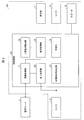
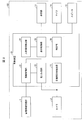
- FIG. 1 It is the schematic of the display apparatus which concerns on Embodiment 1 of this invention. It is a schematic block diagram of the display apparatus shown in FIG. It is a flowchart which shows the flow of a process until the information display in the display apparatus shown in FIG. (A) (b) is a figure which shows the database which the display apparatus shown in FIG. 1 uses. It is a flowchart which shows the flow of a process of the displayed information in the display apparatus shown in FIG. (A)-(c) is a figure explaining the process of the displayed information in the display apparatus shown in FIG. It is a figure which shows the display system provided with the display apparatus shown in FIG. It is a schematic block diagram of a display device according to a modification of the first embodiment.
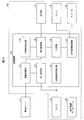
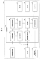
- FIG. 11 It is a schematic block diagram of the display apparatus which concerns on Embodiment 2 of this invention. It is a schematic block diagram of the display apparatus which concerns on the modification of Embodiment 2 of this invention. It is a figure which shows the state before performing an utterance process in the display apparatus shown to FIG. 11 is a flowchart showing the flow of speech processing in the display device shown in FIGS. 11 is a flowchart showing a flow of processing of displayed information in the display device shown in FIGS. (A)-(c) is a figure explaining the process of the displayed information in the display apparatus shown to FIG. It is a schematic block diagram of a display device according to Embodiment 3 of the present invention. (A) (b) is a figure which shows an example of an utterance process before information display. It is a figure which shows an example of the state detection of the identified individual in the display apparatus which concerns on Embodiment 4 of this invention.
- Embodiment 1 Hereinafter, embodiments of the present invention will be described in detail.
- a half mirror will be described as an example of a light transmitting and reflecting member that functions as a mirror.
- FIG. 1 is a diagram for explaining an overview of a display device with a mirror function (hereinafter referred to as a display device) 101 according to the present embodiment.
- the display device 101 is provided around the display unit 11, a half mirror (light transmitting / reflecting member) 12 arranged on the display surface 11 a of the display unit 11, and the display unit 11.
- a camera 13, a microphone 14, and a speaker (speech unit) 15 are provided.
- the display unit 11 is a means for displaying an image, and is composed of a liquid crystal display panel.
- EL organic, inorganic
- PDP Plasma Display Panel
- SED Surface-conduction Electron Emitter Display
- FPD flat panel display
- the half mirror 12 is a light transmitting / reflecting member formed by forming a very thin reflective film on a plate glass or an organic glass such as acrylic so that the incident rate and reflectance of light are the same, and making it semitransparent. is there.
- a commercially available one can be used as the half mirror 12.
- the half mirror 12 is arranged so as to overlap the display surface 11a of the display unit 11, the image displayed on the display surface 11a is transmitted through and projected from the outside toward the display surface 11a. A part of the incident light is reflected to generate a mirror image.
- the mirror image 16 and the images 17a to 17d displayed on the display surface 11a of the display unit 11 can be synthesized in a pseudo manner.
- setting is made on the display surface 11a of the display unit 11 so that the person area 11b that displays the image of the person that has passed through the half mirror 12 and the image area 11c that displays the images 17a to 17d do not overlap.
- the video area 11c is set at a position that does not overlap the person area 11b on the display surface 11a, but is preferably set at a position where a person in front of the display device 101 can easily recognize, that is, a position where the amount of eye movement is small. . That is, the mirror image 16 and various types of information (videos 17a to 17d) are displayed on the display surface 11a. Note that the video area 11c and the person area 11b may be slightly overlapped as long as various information displayed in the video area 11c can be visually recognized.
- the images 17a to 17d displayed in the image area 11c correspond to the person in front of the display device 101, that is, the person of the mirror image 16 displayed on the half mirror 12, and the place where the display device 101 is installed. It becomes information according to.
- “weather forecast” is displayed on the video 17 a
- “today's fortune” is displayed on the video 17 b
- “news” is displayed on the video 17 c
- “traffic information” is displayed on the video 17 d as the above information.
- selection of information displayed in the video area 11c is performed with reference to a database (FIGS. 5A and 5B) described later. Details of this information selection will be described later.
- the camera 13 is a photographing unit (first photographing unit, second photographing unit) for photographing a person in front of the display device 101, and is provided at two locations on the left and right sides of the peripheral portion that does not contribute to the display of the display unit 11. It has been.
- the two cameras 13 are provided in order to measure the distance between the person in front of the display device 101 and the display surface 11 a of the display unit 11.
- the camera 13 is a general small digital camera that uses a CCD (Charge-Coupled Device), CMOS (Complementary-Metal-Oxide-Semiconductor) or the like as an image sensor, and can photograph a person in front of the display device 101. Anything is acceptable.
- CCD Charge-Coupled Device
- CMOS Complementary-Metal-Oxide-Semiconductor
- the camera 13 can capture a corneal reflection image obtained by irradiating the eyeball of the person with infrared rays so as to detect the line of sight of the person in front of the display device 101.
- a person specifying unit for specifying a person in front of the display device 101 is essential. Therefore, in this embodiment, a person in front of the display device 101 is photographed and an individual is specified from the photographed video. Therefore, the person in front of the display device 101 is photographed using the camera 13, and this photographed video is used for personal identification. That is, the camera 13 is used for detecting the eyes of a person in front of the display device 101 and for identifying an individual.
- a camera (first imaging unit) for detecting the eyes of a person and a camera (second imaging unit) for specifying an individual may be provided separately.
- the microphone 14 is a means for capturing sound emitted by a person in front of the display device 101, and is configured by a general microphone used for a smartphone or a mobile phone. Further, an individual may be specified from the voice captured by the microphone 14.
- the speaker 15 is a unit that emits voice to a person in front of the display device 101, and is configured by a general speaker used for a smartphone, a mobile phone, or the like.
- the speaker 15 is also used as a means for notifying a user of information necessary for the person in front of the display device 101 by voice.
- the speaker 15 emits information corresponding to the video images 17a to 17d displayed on the display surface 11a of the display unit 11 and notifies the person in front of the display device 101.
- the camera 13 may be used to detect the movement of a person in front of the half mirror 12.
- the result of the motion detection is input to the control device 20, and a command corresponding to the motion is executed (a gesture input process).
- a command corresponding to the motion is executed (a gesture input process). For example, the fingertip of a person may be detected, its movement detected, and customization information displayed at the position pointed by the fingertip may be selected.
- the display device 101 is connected to the management server 2 via a network, and includes a display unit 11, a camera 13, a microphone 14, a speaker 15, and a control device 20 for controlling them.
- the control device 20 includes an information acquisition unit (information acquisition unit) 21, an individual identification unit (person identification unit) 22, an eye movement destination detection unit (eye movement destination detection unit) 23, a person area detection unit (area detection unit) 24, A display control unit (display control unit) 25 and a specifying unit 26 are included.
- the personal identification unit 22 identifies a person in front of the display device 101. Specifically, the individual identifying unit 22 identifies a person from a captured video obtained by photographing a person in front of the display device 101 with the camera 13. For example, information on a person (face image) is registered in advance, and a person (hereinafter referred to as an individual) is specified by determining whether or not the captured video is a registered face image. In this case, by assigning an ID to each registered face image, the identified individual ID is sent to the information acquisition unit 21 as the identified individual information.
- the person in front of the display device 101 in addition to the method of using the captured image using the camera 13 as described above, acquiring information from the wearable device worn by the individual.
- the individual may be specified by.
- information from the wearable device worn by the person is sent to the personal identification unit 22 inside the display device 101.
- the wearable device and the display device 101 are connected by wireless communication such as infrared communication, WIFI (registered trademark), and Bluetooth (registered trademark). Note that the transmission of information from the wearable device to the display device 101 may be wired communication or may be transmitted via a network in addition to the wireless communication described above.
- the method for identifying the person in front of the display device 101 is not limited to the above-described two individual identification methods, and for example, an individual identification method using voice may be used.
- an individual identification method using voice may be used.
- the individual specifying unit 22 specifies the individual by collating with voice data registered in advance.
- voice in order to prevent the person from being identified in the state where the person is not in front of the display device 101, it is detected by voice after detecting the presence of the person in front of the display device 101. Identify individuals.
- the information acquisition unit 21 acquires necessary information from the management server 2 connected via a communication network such as the Internet.
- the necessary information is customization information corresponding to the individual specified by the individual specifying unit 22.
- the customization information is information (customization information) customized according to each individual among information preset for each installation location of the display device 101.
- the customer information includes, for example, the weather forecast shown in FIG. 1, today's fortune-telling, news, and traffic information. These customization information is sent to the display control unit 25.
- the customization information is information set for each individual and for each installation location of the display device 101, for example, “information to be displayed” shown in FIG. 4B, and further includes information reflecting personal preferences. You may go out.
- the person area detection unit 24 detects an area (person area 11b) in which an image of a person transmitted through the half mirror 12 is displayed on the display surface 11a.
- the distance between the display device 101 and the person is obtained from the captured image of the person in front of the display device 101 photographed by the two cameras 13, and the mirror image 16 projected on the half mirror 12 is obtained from this distance.
- a method of obtaining the size and the display position and detecting the display position of the mirror image 16 projected on the display surface 11a of the display unit 11 of the display device 101 as the person region 11b may be used.
- the number of cameras 13 may be one.
- the person area 11 b detected by the person area detection unit 24 is sent to the display control unit 25.
- the display control unit 25 controls the display position of the video to be displayed on the display surface 11a of the display unit 11. Specifically, the display control unit 25 specifies the display position of the person area 11b from the person area detection unit 24, sets an area that does not overlap the person area 11b (the video area 11c in FIG. 1), and The display unit 11 is controlled to display the customization information acquired by the information acquisition unit 21 in the video area 11c.
- the display control unit 25 can convert the captured image from the camera 13 to a desired size and display it as a photographed image of a person at a desired position on the display surface 11a of the display unit 11.
- the line-of-sight movement destination detection unit 23 detects where the line of sight of the person in front of the display device 101 (the line-of-sight movement destination) is on the display surface 11 a of the display unit 11. Specifically, the eye movement destination detection unit 23 detects the eye movement destination of the person from the cornea reflection image of the eyeball of the person in front of the display device 101 photographed by the camera 13.
- the eye movement destination detection unit 23 may be any detection unit as long as the eye eye movement destination can be detected in addition to the corneal reflection image taken by the camera 13.
- Information on the detected eye movement destination is sent to the specifying unit 26.
- the detected information of the eye movement destination is information indicating the coordinate position of the display surface 11a, but is not limited to this, and any information that can specify the position in the display surface 11a can be used. May be correct information.
- the specifying unit 26 specifies customization information of a position corresponding to the eye movement destination detected by the eye movement destination detection unit 23, and determines what information the specified customization information is. For example, if there is a video 17d at a position corresponding to the eye movement destination among the videos 17a to 17d in the video area 11c shown in FIG. 1, it is determined what information the video 17d is. In the case of FIG. 1, the video 17 d is “traffic information”. Therefore, the eye movement destination of the person in front of the display device 101 is “traffic information”. The information selected by the specifying unit 26 is sent to the display control unit 25.
- the specifying unit 26 specifies information based on the information of the person's eye movement destination, but is not limited thereto, and specifies information using information based on the person's voice or gesture. May be.
- the microphone 14 captures the voice “traffic information” and sends it to the specifying unit 26.
- the identifying unit 26 performs existing voice recognition processing, and determines that the information selected by the person in front of the display device 101 is “traffic information”.
- a gesture recognition unit recognizes, for example, a hand from a captured image obtained by photographing a person corresponding to the mirror image 16 by the camera 13, and the display surface 11a pointed to by the recognized hand. Get the coordinate position of.
- the acquired coordinate position is sent to the specifying unit 26.
- any one of the images 17a to 17d displayed on the display surface 11a is selected from the sent coordinate position, and information corresponding to the selected image 17 is determined. For example, if there is a video 17d at the coordinate position among the videos 17a to 17d in the video area 11c shown in FIG. 1, this video 17d is selected, and it is determined what information this video 17d is.
- the display control unit 25 displays the information specified by the specifying unit 26 (any one of the videos 17a to 17d displayed in the video area 11c in FIG. 1) at a position where a person in front of the display device 101 can easily see.
- the selected information is displayed at this position.
- the mirror image display area is detected (step S11).
- the display area of the person image formed on the half mirror 12 is detected by the person area detection unit 24 of the control device 20. Specifically, the person area 11b shown in FIG. 1 is detected.
- the method for detecting the display area of the mirror image 16 is performed by the method described above.
- step S12 an individual is specified (step S12).
- the person in front of the display device 101 is specified by the individual specifying unit 22 of the control device 20.
- the individual identification method is performed by the method described above.
- step S13 information tailored to the individual (customized information) is acquired.
- the information acquisition unit 21 of the control device 20 acquires information that matches the person in front of the display device 101 from the management server 2.
- step S14 the display control unit 25 of the control device 20 sets the video area 11c serving as the information display position at the display position of the mirror image 16 detected in step S11, that is, the position not overlapping the person area 11b in FIG.
- the acquired information is displayed in the video area 11c.
- the information to be acquired (customized information displayed on the display device 101) varies depending on the installation location of the display device 101. This is because, as shown in FIG. 4A, the purpose, time / scene, mirror image, and time in front of the mirror differ depending on the place where the display device 101 is installed.
- the installation location of the display device 101 is a wash basin, its purpose is face washing, tooth brushing, and hand washing.
- the time and scene in which the washstand is used is generally determined, and when waking up, before going to bed.
- the mirror image of the display device 101 installed on the washstand is above the chest, mainly the face, and the time in front of the mirror is relatively long. Therefore, as shown in FIG. 4B, the display device 101 installed in the washstand basically has all information such as news, weather forecast, traffic information, fortune telling, mace, SNS (Social Network Service), etc. Is displayed. However, some information is not displayed depending on the time.
- the information to be displayed varies depending on the purpose, time / scene, mirror image, and time in front of the mirror.
- the database shown in FIGS. 4A and 4B is set for each individual. By attaching an ID for identifying an individual to the database, it is possible to acquire customized information corresponding to the individual from the identified individual ID. That is, in the display device 101, an individual is specified by the individual specifying unit 22, and customization information corresponding to the individual is acquired by reading the corresponding database from the management server 2 from the ID of the individual specified by the information acquisition unit 21. It becomes possible to do.
- the database corresponding to the individual sets, for example, “information to be displayed” shown in FIG. 4B according to information related to the individual (gender, date of birth, favorite color, hobby, etc.). Database.
- the items shown in FIG. 4A may be set in accordance with information related to individuals.
- Customized information can be provided at an appropriate time.
- the eye movement destination of the person in front of the display device 101 is detected (step S21).
- the eye movement destination detection unit 23 detects the eye movement destination from the cornea reflection image of the human eyeball in front of the display device 101.
- step S22 it is determined whether or not a predetermined time has passed at the same position at the detected eye movement destination (step S22).
- the specifying unit 26 determines whether or not a predetermined time has elapsed for the time during which the detected eye movement destination does not move (the time during which the person is gazing).
- the eye movement destination detection unit 23 detects the eye movement destination in step S21 again.
- the display control unit 25 displays the customization information specified by the specifying unit 26.
- the area is exchanged with a display area for a human image. Or it transfers to step S23 and the display control part 25 replaces the display position of the image
- FIG. 6A shows an example in which the eye movement destination is detected as the video 17d and the video 17d is selected.
- the detection destination video 17d is changed to a thick frame in order to distinguish it from the other videos 17a to 17c.
- the position where the traffic information displayed in the video 17d is easy to see that is, the display position of the mirror image 16 And is displayed as an image 17d '.
- a photographed video 16 'obtained by photographing the person in front of the display device 101 with the camera 13 is displayed at the position where the original video 17d is displayed.
- the image of the movement destination is displayed at an easy-to-see position.
- a ring 18 indicating that the photographed image 16 ′ has been selected is displayed as shown in FIG. 6C, and when a predetermined time elapses in this state. Again, as shown in FIG. 6A, the mirror image 16 is displayed.
- the person in front of the display device 101 can confirm necessary information at a position where it can be easily seen while confirming his / her appearance.
- FIG. 7 is a diagram showing an overview of a display system including a plurality of display devices 101 in the home and the management server 2.
- the display device 101 is installed in a wash basin, a mirror stand, a figure, a front door, and a bathroom assuming that it is used in the home.
- the installation location is not limited to these.
- symbols a to e are added for convenience in order to distinguish the display device 101 for each installation location. That is, the display device 101a is used for the washstand, the display device 101b is used for the mirror table, the display device 101c is used for the appearance, the display device 101d is used for the entrance, and the display device 101e is used for the bathroom.
- the display devices 101a to 101e at each installation location are connected to the management server 2 via the network, acquire necessary information from the management server 2, and transmit information to be stored. is doing.
- the management server 2 stores information to be displayed as the video 17 displayed on the display device 101 shown in FIG.
- the management server 2 sends information that requires immediateness, such as weather forecasts, today's fortune-telling, news, and traffic information, from the outside via a network (Internet). Get it regularly.
- the acquired information is associated with an item corresponding to the display device 101 at each installation location in the database (FIGS. 4A and 4B) in the management server 2 and the display device 101 at the installation location requested to be transmitted. Sent to.
- each display device 101 is connected to the common management server 2, it is possible to display common information.
- the common information in this case is, for example, “foreign information to be displayed” shown in FIG. 4B, weather forecast and traffic information except for the place where the display device 101 is installed in the bathroom. That is, it is possible to display the weather forecast and traffic information on all the display devices 101 that are viewed by the individual from getting up to work. As a result, the user can confirm the information to be confirmed at any time from when he / she wakes up to work, thereby preventing the user from forgetting to confirm the information.
- the display color of the selected information is selected.
- a display color for example, gray
- traffic information at the time of attendance
- traffic information at the time of attendance
- FIG. 8 is a block diagram illustrating an outline of the display device 102 in which the information acquisition unit 21 acquires the information acquired from the management information storage unit 3 provided inside the device.
- the display device 102 basically has the same configuration as the display device 101 shown in FIG. 3, but the acquisition source of information displayed on the display surface 11 a of the display unit 11 is changed from the management server 2 to the management information storage unit 3. ing.
- the display device 102 can execute the same function as the display device 101 shown in FIG.
- immediacy information weather forecast, traffic information, etc.
- Information with immediacy is acquired by connecting the management information storage unit 3 to a network such as the Internet.
- the display device 102 having the above configuration is effective when there is only one installation location and immediacy information is almost unnecessary.
- FIG. 9 is a block diagram illustrating an outline of the display device 103 according to the present embodiment.
- a voice recognition processing unit speech recognition processing unit, speech unit 27 and a voice recognition database 28 are newly added to the display device 101 shown in FIG. Yes.
- the voice recognition processing unit 27 converts the information specified by the specifying unit 26 into voice data, and sends the converted voice data to the speaker 15. Information is output from the speaker 15 by voice.
- the display control unit 25 outputs information displayed on the display surface 11a of the display unit 11 to the speaker 15 as voice data.
- the voice recognition processing unit 27 outputs the voice data to the speaker 15 in accordance with the timing for displaying information on the display surface 11a, or the voice data at a timing later than the timing for displaying information on the display surface 11a. Output to the speaker 15.
- the voice recognition processing unit 27 not only performs processing for outputting information by voice, but also recognizes voice data input from the microphone 14 and outputs a command corresponding to the recognized voice data to the specifying unit 26.
- the command is stored in the voice recognition database 28 in association with the voice data.
- the command is a command for selecting information. That is, the voice data input from the microphone 14 is recognized, and a command corresponding to the recognized voice data is read from the voice recognition database 28 and sent to the specifying unit 26, so that the specifying unit 26 responds to the sent command. Select the corresponding information.
- the speech recognition processing unit 27 and the speech recognition database 28 may be configured to be referred to by connecting to a network such as the Internet.
- the acquisition destination of the information selected by the specifying unit 26 is the management server 2.
- the information acquisition destination may be the display device 104 using the management information storage unit 3 as shown in FIG.
- FIG. 11 is a diagram showing a state in which a mirror image of a person is projected in front of the display device 103 (104). Even after information is acquired, this state (information is not displayed and only the mirror image 16 is displayed). State). This point is different from FIG. 1 of the first embodiment.
- an individual is specified (step S31).
- the person in front of the display device 103 is specified by the individual specifying unit 22 of the control device 20.
- the personal identification method is performed in the same manner as in the first embodiment, and detailed description thereof is omitted.
- step S32 information tailored to the individual is acquired.
- the information acquisition unit 21 of the control device 20 acquires information that matches the person in front of the display device 103 from the management server 2.
- step S33 the acquired information is output as a voice (step S33).
- the information acquired in step S32 is converted into voice data by the voice recognition processing unit 27 of the control device 20, and the speaker 15 speaks.
- a voice instruction of a person in front of the display device 103 is recognized (step S41).
- the voice recognition processing unit 27 recognizes the contents of the voice instruction from the voice data uttered by the person in front of the display device 101 toward the microphone 14. This content is an information selection instruction.
- step S42 information is displayed according to the recognized instruction (step S42).
- the information selected by the specifying unit 26 that has received the content of the voice instruction recognized by the voice recognition processing unit 27 is displayed on the display surface 11 a of the display unit 11.
- the mirror image 16 is converted into a captured image 16 ′ captured by the camera 13, and the captured image 16 ′ is displayed at a position different from the information display position.
- the eye movement destination detection unit 23 detects the eye movement destination from the cornea reflection image of the human eyeball in front of the display device 103.
- step S44 it is determined whether or not a predetermined time has passed at the same position at the detected eye movement destination (step S44).
- the specifying unit 26 determines whether or not a predetermined time has elapsed for the time during which the detected eye movement destination does not move (the time during which the person is gazing). If the eye movement destination has moved without a predetermined time (No in step S44), eye movement destination detection by the eye movement destination detection unit 23 is performed again in step S43. On the other hand, if the predetermined time has elapsed (Yes in step S44), it is considered that a person has selected a certain video, the process proceeds to step S45, and the display control unit 25 displays the video display area specified by the specifying unit 26. Is replaced with the display area of the mirror image 16.
- FIG. 14 (a) only the mirror image 16 is displayed on the display unit 11, and the person corresponding to the mirror image 16 from the state where the individual is identified and the acquisition of information is completed, that is, the display
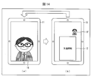
- a person in front of the device 103 speaks “traffic information” to the microphone 14, as shown in FIG. 14B, an image 17 indicating the traffic information is displayed at the display position of the mirror image 16.
- a photographed video 16 ′ obtained by photographing a person in front of the display device 103 with the camera 13 is displayed at a position different from the display position of the video 17. The same operation is performed when displaying other information.
- a person in front of the display device 103 can confirm necessary information at a position where it can be easily seen while confirming his / her appearance.
- the example in which the information displayed on the display surface 11a of the display unit 11 is selected by a voice command and the display devices 103 and 104 are uttered has been described.
- An example of speaking from the display device side to a person who is in the office will be described.
- FIG. 15 is a block diagram illustrating an outline of the display device 105 according to the present embodiment.
- the display device 105 is substantially the same as the display device 103 shown in FIG. 9 of the second embodiment, and is different in that an utterance database 29 is provided instead of the speech recognition database 28.
- the person identifying unit 22 identifies a person in front of the display device 105, and utters content (information customized according to the person) that matches the identified person from the speaker 15 of the display device 105. To do.
- the commands corresponding to the voice data described in the second embodiment are stored in association with each other, but also the specified person in the state where the person in front of the display device 105 is specified.
- the utterance content to be uttered is stored. For example, in the case of the display device 103 installed in the wash basin, if the time is 7 o'clock, “Good morning. The weather is sunny” is displayed from the speaker 15 to the specified person in front of the display device 103. Try to speak.
- This utterance content is stored in the utterance database 29 as a database so that it can be changed according to the installation location, time, and specified person of the display device 103.
- the voice recognition processing unit 27 makes a reply “Today is sunny” by referring to the information on the weather forecast acquired by the information acquisition unit 21.
- the display device 105 As in the display device 103, information tailored to the specified individual is displayed on the display surface 11a of the display unit 11, but before the display of these information, the display device 105 is displayed. You may speak to a person who is in or speak from a person.
- FIG. 16A shows an example in which a mirror image before utterance is displayed
- FIG. 16B shows an example in which a past photographed image is superimposed on the mirror image in FIG.
- the management server 2 stores video shot of each individual in association with the date and time, and transmits the video shot of the individual at the specified date and time to the display device 105.
- the display device 105 identifies the person by the individual identification unit 22.
- the voice data with the content “??” utters “Recently?” To the person through the speaker 15.
- the voice recognition processing unit 27 receives the voice data “Is it?” From the microphone 14 and sends a command corresponding to this voice data. Read from the utterance database 29, and output the read command to the information acquisition unit 21.
- the information acquisition unit 21 reads a past captured video of the person managed by the management server 2 from the command, outputs the past captured video to the display control unit 25, and superimposes it on the mirror image 16 in the display unit 11. Display.
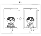
- FIG. 16B is a diagram showing a state where the read past captured video 116 is superimposed on the current mirror image 16.
- the photographed image 116 read out for comparison with the mirror image 16 is a photographed image one month or more before the present. This is because the body shape does not change so much in one day or two days, but it is highly likely that the body shape has changed one month ago or more.
- the past captured video 116 to be read is not limited to the one captured at one time point, but may be superimposed on the captured video images 116 at a plurality of time points (for example, one month ago, three months ago, six months ago, one year ago) You may make it display along with the position of the display surface 11a which does not overlap with the mirror image 16.
- FIG. Thereby, the person of the mirror image 16 can easily confirm that his / her body shape has changed from his / her own captured video.
- a person in front of the display device 105 is further specified, and the state of the person, for example, the hairstyle, facial expression, clothing color, the presence or absence of a hat, or the like is detected from the captured video of the specified person.
- the state of the person for example, the hairstyle, facial expression, clothing color, the presence or absence of a hat, or the like is detected from the captured video of the specified person.
- the individual identification unit 22 shown in FIG. 2 further detects the state of the person from the captured video of the camera 13 used for identification of the individual.
- the state of the person includes a hairstyle, facial expression, clothing color, presence / absence of a hat, etc., as described above.
- the person in front of the display device 101 is rotated and photographed by the camera 13 when the front mirror image 16 shown in FIG.
- the determination of the front and back of a person is performed by image recognition.
- image recognition if there is a face, it is determined to be the front, and if there is no face, it is determined to be the back.
- the hairstyle of the person is detected from the captured images (front and back) obtained by rotating the person in front of the display device 101. Accordingly, the person can be informed of the presence or absence of the disorder of the person's hair from the detected hairstyle. Although the front of the hair can be actually seen and judged, it is difficult to confirm the back of the hair by yourself, so the above notification is effective.
- a position that does not overlap with the mirror image 16 of the display surface 11a of the display unit 11, for example, the “hair state” may be displayed on the video area 11c, or, similarly to the second and third embodiments.
- the hair state for example, “the back hair is distorted” may be notified by voice.
- the degree of fatigue is calculated by comprehensively determining the presence or absence of skin tension, sagging, wrinkles, and bears under the eyes by analyzing the face image.
- information associated with the detected clothing color may be presented to the person.
- information associated in this case for example, fortune-telling based on the color of clothes can be mentioned.
- advice information indicating whether the coordination between the color of the clothes and the presence / absence of the hat is appropriate is presented to the person. You may do it.
- the absence of a hat is detected as a specified individual status, if it is predicted from the weather forecast for the day that the sun is strong and the amount of ultraviolet rays is high, it will be communicated to that effect and will be instructed to wear the hat.
- the information to be displayed may be presented to the person.
- the display devices 101 to 105 use the half mirror 12 as a means for realizing the mirror function, but the means for realizing the mirror function is limited to the half mirror 12. is not.
- the half mirror 12 may be a light-transmitting / reflecting member in which the light transmittance and the light reflectance are equal, but the light transmittance and the light reflectance are different.
- control blocks (control device 20) of the display devices 101 to 105 may be realized by a logic circuit (hardware) formed in an integrated circuit (IC chip) or the like, or software using a CPU (Central Processing Unit). It may be realized by.
- the control device 20 includes a CPU that executes instructions of a program that is software that implements each function, a ROM (Read Only Memory) in which the program and various data are recorded so as to be readable by a computer (or CPU), or A storage device (these are referred to as “recording media”), a RAM (Random Access Memory) for expanding the program, and the like are provided.
- a computer or CPU
- the recording medium a “non-temporary tangible medium” such as a tape, a disk, a card, a semiconductor memory, a programmable logic circuit, or the like can be used.
- the program may be supplied to the computer via an arbitrary transmission medium (such as a communication network or a broadcast wave) that can transmit the program.
- a transmission medium such as a communication network or a broadcast wave
- the present invention can also be realized in the form of a data signal embedded in a carrier wave in which the program is embodied by electronic transmission.
- the display device is a display device in which a light transmission / reflection member (half mirror 12) that transmits part of light and reflects part of the light is disposed on the display surface 11 a of the display unit 11.
- a region detecting unit for detecting a region (person region 11b) in which the human image 16 transmitted through the light transmitting / reflecting member (half mirror 12) is displayed on the display surface 11a; Information generated according to the person specified by the person specifying unit (individual specifying unit 22) from information associated with the person specifying unit (person specifying unit 22) for specifying a person and the installation location of the display device Information acquisition unit (information acquisition unit 21) for acquiring information as customization information, and customization information acquired by the information acquisition unit (information acquisition unit 21) on the display surface 11a. It is characterized in that it comprises, a display control unit 25 for displaying the detected area (person area 11b) and the different areas (image area 11c) by the person area detection unit 24).
- generated according to the person is acquired as customization information from the information matched with the installation place of the display apparatus by the display control part 25, and the acquired customization information is displayed on a display surface.
- the user in front of the display device can confirm his / her mirror image displayed on the light transmitting / reflecting member. It becomes possible to confirm customization information.
- the customization information is a string for each installation location of a display device with a mirror function (a place where a display device with a mirror function is supposed to be installed in a household such as a washstand, a mirror stand, a figure, a front door, a bathroom, etc.). It refers to various information attached. For example, information linked to the wash basin, which is one of the installation locations, such as news, weather forecasts, traffic information, fortune telling, e-mail, etc., taking into account usage time / use scene, mirror image, time in front of the mirror Can be mentioned.
- the display device having the above configuration it is possible to acquire necessary information for a person in front of the display device at an appropriate timing in consideration of the installation location of the display device, so that the user stands in front of the display device. As a result, it is possible to obtain and display information necessary for the user at an appropriate timing.
- the display control unit 25 converts the customization information acquired by the information acquisition unit 21 into the region detection unit (person region detection) on the display surface 11a.
- the image is displayed in a region (video region 11c) that does not overlap the region (person region 11b) detected by the unit 24).
- the information tailored to the individual and the mirror image are displayed by displaying the information tailored to the individual acquired by the information acquisition unit at a position on the display surface of the display unit that does not overlap the mirror image of the person. Are surely separated and displayed. Thereby, it becomes easy to confirm information tailored to the individual displayed on the display unit.
- the display device includes the specifying unit 26 that specifies the customization information specified by the user in the above-described aspect 1 or 2, and the display control unit 25 includes the customization specified by the specifying unit 26.
- Information may be displayed on the person area (display unit 11) on the display surface 11a.
- the user can easily confirm necessary information by displaying the selected information among the information matched to the individual at the display position of the mirror image of the person.
- the display device is the first image capturing in which the person specified by the person specifying unit (person specifying unit 22) is imaged from the light transmitting / reflecting member (half mirror 12) side.
- the display control unit 25 includes an area (person area 11b) detected by the area detection unit (person area detection unit 24) for the customized information determined to be specified by the specifying unit 26. ) And an image of the person imaged by the first image capturing unit (camera 13) on the display surface 11a detected by the area detecting unit (person area detecting unit 24) (person area 11b). ) May be displayed in an area other than.
- the specified customization information is displayed in the area where the mirror image of the person is displayed among the customization information corresponding to the individual, so that the specified customization information can be easily viewed by the user. Will be displayed. Further, since the mirror image of the original individual is displayed at a position different from the display position of the information selected as the captured video, it is possible to view the captured video while confirming the selected information.
- the display device further includes a line-of-sight movement destination detection unit 23 that detects the movement destination of the line of sight of the person identified by the person identification unit (individual identification unit 22) in the above-described aspect 3 or 4.
- the specifying unit 26 determines that the customization information is specified when the destination of the person's eyes detected by the eye movement destination detection unit 23 is one of the customization information displayed on the display surface 11a.
- the display control unit 25 determines the customization information determined to be specified by the specifying unit 26 as a region (person region) detected by the region detection unit (person region detection unit 24) on the display surface 11a. 11b) may be displayed.
- any of the customization information corresponding to the individual displayed on the display unit 11 is specified by detecting the movement destination of the line of sight of the person in front of the display device. Can do. That is, the user can identify information suitable for himself and confirm the information only by moving his eyes while confirming his mirror image.
- the display device is the display device according to any one of Aspects 1 to 5, wherein the second imaging unit (camera 13) that captures a person in front of the light transmission / reflection member (half mirror 12) is provided.
- the person specifying unit (individual specifying unit 22) may specify a person from a video image of the person shot by the second shooting unit (camera 13).
- the display device according to aspect 7 of the present invention is the display device according to any one of the above aspects 1 to 5, wherein the person specifying unit (individual specifying unit 22) uses information acquired from a wearable device storing information for specifying a person. It is preferable to specify a person.
- the wearable device for identifying an individual, it is possible to identify the individual more reliably than the identification of the individual using the captured video.
- the display device is a display device in which a light transmission / reflection member (half mirror 12) that transmits part of light and reflects part of the light is disposed on the display surface 11 a of the display unit 11.
- the person specifying unit person specifying unit 22
- the information acquisition unit 21 that acquires information generated according to the person specified by the specifying unit (personal specifying unit 22) as customization information, and the customization information acquired by the information acquisition unit 21 are output by voice.
- An utterance unit (voice recognition processing unit 27) is provided.
- the user who is in front of the light transmitting / reflecting member outputs the mirror image of the user reflected on the light transmitting / reflecting member by outputting the customized information acquired by the information acquiring unit by voice by the utterance unit. While confirming, it is possible to confirm customization information tailored to yourself.
- the customization information is a string for each installation location of a display device with a mirror function (a place where a display device with a mirror function is supposed to be installed in a household such as a washstand, a mirror stand, a figure, a front door, a bathroom, etc.). It refers to various information attached. For example, information linked to the wash basin, which is one of the installation locations, such as news, weather forecasts, traffic information, fortune telling, e-mail, etc., taking into account usage time / use scene, mirror image, time in front of the mirror Can be mentioned.
- the display device having the above configuration it is possible to acquire necessary information for a person in front of the display device at an appropriate timing in consideration of the installation location of the display device, so that the user stands in front of the display device. As a result, it is possible to output information necessary for the user at an appropriate timing.
- the display device preferably includes a display control unit 25 that causes the display surface 11a to display the customization information acquired by the information acquisition unit 21 in the above aspect 8.
- the utterance unit may output the customization information by voice before the customization information is displayed on the display surface 11a.
- the person region that detects the person region 11b in which the image of the person transmitted through the light transmitting and reflecting member (half mirror 12) is displayed on the display surface 11a is detected.
- the display control unit 25 may include the detection unit 24 and may display the customization information acquired by the information acquisition unit 21 in an area that does not overlap the person area 11b on the display surface 11a.
- the customization information acquired by the information acquisition unit 21 is displayed on the display surface 11a of the display unit 11 at a position that does not overlap the person region 11b. Are surely separated and displayed. Thereby, it becomes easy to confirm the customization information displayed on the display unit 11.
- the display device includes the specifying unit 26 that specifies customization information specified by the user in the above-described aspect 11, and the display control unit 25 displays the customization information specified by the specifying unit 26.
- the person area 11b on the display surface 11a may be displayed.
- the specifying unit 26 generates one of the customization information displayed on the display surface based on the sound emitted by the person specified by the person specifying unit 26. You may choose.
- the identified individual can appropriately select the desired information simply by emitting a voice. That is, the user can select the customized information and confirm the information only by uttering the sound while confirming his / her mirror image.
- the display device according to aspect 14 of the present invention is the display device according to any one of the above aspects 8 to 13, further comprising a photographing unit that photographs a person present on the light reflecting surface side of the light transmitting / reflecting member. 26 may identify a person from the video of the person photographed by the photographing unit.
- the display device according to aspect 15 of the present invention is the display device according to any one of the above aspects 8 to 13, wherein the person specifying unit 26 selects a person based on the person information acquired from the wearable device that stores the person information specifying the person. You may specify.
- the wearable device for identifying an individual, it is possible to identify the individual more reliably than the identification of the individual using the captured video.
- the display device according to aspect 16 of the present invention is the display device according to any one of the aspects 1 to 15, wherein the information acquisition unit 21 receives a person from the management server 2 that manages the customization information via a communication network. It is preferable to obtain customization information according to the above.
- any display device can be used as long as the user is a display device connected to the same management server 2.
- the same information can be obtained by using.
- the display device connected to the same management server 2 is used at the entrance to the wash basin, the mirror stand, the figure, etc., which will be used until the user wakes up and works at home, for example. If the user is installed, the user can continue to check the same information before getting up and going to work.
- the present invention can be used for a display device with a mirror function installed at a place where the user's purpose and use time as a mirror are different, particularly a display device with a mirror function installed at each place in the home.
- management server 3 management information storage unit 11 display unit 11a display surface 11b person area 11c video area 12 half mirror (light transmission / reflection member) 13 cameras (first and second imaging units) 14 Microphone 15 Speaker (speaking part) 16 Mirror image 16 'Shooting video 17 Video (information) 18 Ring 20 Control device 21 Information acquisition unit 22 Individual identification unit (person identification unit) 23 Eye movement destination detection unit 24 Human region detection unit (region detection unit) 25 Display control unit 26 Identification unit 27 Voice recognition processing unit (voice recognition processing unit, speech unit) 28 Speech recognition database 29 Utterance database 101 to 105 Display device 116 Photographed video
Landscapes
- Engineering & Computer Science (AREA)
- Physics & Mathematics (AREA)
- General Physics & Mathematics (AREA)
- Theoretical Computer Science (AREA)
- Computer Hardware Design (AREA)
- Controls And Circuits For Display Device (AREA)
Abstract
鏡の設置場所を考慮し、鏡の前に居る人物に対して必要な情報を適切なタイミングで提供する。本発明に係る表示装置(101)は、表示装置(101)の設置場所と対応付けられた情報に基づいて、人物に応じて生成されたカスタマイズ情報(17a~17d)を、表示部(11)の表示面(11a)における、人物の像を表示する人物領域(11b)と異なる映像領域(11c)に表示する。
Description
本発明は、表示装置に関し、特に、表示面において、光の一部を透過し、一部を反射する光透過反射機能を有する表示装置に関する。
一般に、表示面において、光の一部を透過し、一部を反射する光透過反射機能を有する表示装置、所謂ミラー機能付き表示装置では、表示装置の表示面に表示された情報(画像も含む)は、鏡像とともに映し出される。
例えば、特許文献1には、鏡像に重ならない位置に、ユーザの行動に関する生活情報映像を表示する情報表示装置が開示されている。
ところで、ミラー機能付きの表示装置の設置場所として、洗面台、鏡台、クローゼット、玄関などが考えられ、これら設置場所によって、ユーザの鏡を使用する目的や使用する時間が異なる。このため、ユーザが欲する情報も異なる。例えば洗面台では、洗顔、歯磨き、手洗いを目的とし、使用する時間も比較的長いため、ユーザが欲する情報は、天気予報、交通情報に加えて、ニュース、占い、メールなどほとんど全ての情報が該当し、玄関では、身だしなみのチェックを行うことを目的とし、使用する時間はとても短いため、ユーザが欲する情報は、天気予報、交通情報といった外出時に最低限必要な情報が該当する。
しかしながら、特許文献1では、ユーザの取り得る複数の行動と、これらの行動に関連する映像との関係を示す行動情報を、生活情報映像として、鏡の前に居るユーザに提示しているだけである。つまり、特許文献1では、ユーザの一般的な行動パターンから導き出される一般的な生活情報映像を提示しているだけであり、表示装置の設置場所を考慮して、情報の提供を行っていない。
このように、特許文献1では、表示装置の設置場所を考慮して、情報の提供を行っていないため、表示装置の前に居るユーザにとって必要な情報を適切なタイミングで提供でないという問題が生じる。
本発明は、上記の問題点に鑑みなされたものであって、その目的は、鏡の設置場所を考慮し、鏡の前に居る個人に対して必要な情報を適切なタイミングで提供できる表示装置を提供することにある。
上記の課題を解決するために、本発明の一態様に係る表示装置は、光の一部が透過し、一部が反射する光透過反射部材を、表示部の表示面上に重ねて配置した表示装置において、上記光透過反射部材を透過した人物の像が上記表示面に表示される人物領域を検出する領域検出部と、上記人物を特定する人物特定部と、表示装置の設置場所と対応付けられた情報から、上記人物特定部によって特定された人物に応じて生成された情報を、カスタマイズ情報として取得する情報取得部と、上記情報取得部によって取得されたカスタマイズ情報を、上記表示面における、上記領域検出部によって検出された人物領域と異なる領域に表示させる表示制御部と、を備えることを特徴としている。
また、上記の課題を解決するために、本発明の一態様に係る表示装置は、光の一部が透過し、一部が反射する光透過反射部材を、表示部の表示面上に重ねて配置した表示装置において、上記光透過反射部材の光反射面側に存在する人物を特定する人物特定部と、表示装置の設置場所と対応付けられた情報から、上記人物特定部によって特定された人物に応じて生成された情報を、カスタマイズ情報として取得する情報取得部と、上記情報取得部によって取得されたカスタマイズ情報を、音声で出力する発話部と、備えていることを特徴としている。
本発明の一態様によれば、ユーザが表示装置の前に立つだけで、表示装置の設置場所に応じた情報であり、かつ、ユーザにとって必要な情報(カスタマイズ情報)を適切なタイミングで取得して表示させることができるという効果を奏する。
また、本発明の一態様によれば、ユーザが表示装置の前に立つだけで、表示装置の設置場所に応じた情報であり、かつ、ユーザにとって必要な情報を音声により適切なタイミングで確認できるという効果を奏する。
〔実施形態1〕
以下、本発明の実施の形態について、詳細に説明する。本実施形態では、ミラー(鏡)として機能する光透過反射部材として、ハーフミラーを例に説明する。
以下、本発明の実施の形態について、詳細に説明する。本実施形態では、ミラー(鏡)として機能する光透過反射部材として、ハーフミラーを例に説明する。
(表示装置の概要)
図1は、本実施形態に係るミラー機能付き表示装置(以下、表示装置と称する)101の概要を説明するための図である。
図1は、本実施形態に係るミラー機能付き表示装置(以下、表示装置と称する)101の概要を説明するための図である。
表示装置101は、図1に示すように、表示部11と、表示部11の表示面11a上に重ねて配置されたハーフミラー(光透過反射部材)12と、表示部11の周囲に設けられた、カメラ13と、マイク14、スピーカ(発話部)15とを備えている。
表示部11は、映像を表示する手段であり、液晶表示パネルからなり、液晶表示パネル以外の、EL(有機、無機)、PDP(Plasma Display Panel)、SED(Surface-conduction Electron-emitter Display)等のFPD(フラットパネルディスプレイ)であってもよい。
ハーフミラー12は、光の入射率と反射率とが同じになるように、板ガラス、あるいはアクリルなどの有機ガラスに、反射膜をごく薄く形成し、半透明にして形成された光透過反射部材である。ハーフミラー12としては、市販されているものを使用することができる。
ハーフミラー12は、上述のように、表示部11の表示面11a上に重ねて配置されているので、当該表示面11aに表示される映像を透過して映し出し、外部から表示面11aに向かって入射される光の一部を反射して鏡像が生成される。これにより、図1に示すように、ハーフミラー12上で、鏡像16と、上記表示部11の表示面11aに表示された映像17a~17dとを擬似的に合成することができる。
図1に示す例では、表示部11の表示面11aにおいて、ハーフミラー12を透過した人物の像を表示する人物領域11bと、映像17a~17dを表示する映像領域11cとが重ならないように設定されている。映像領域11cは、表示面11aにおける人物領域11bに重ならない位置に設定されるが、表示装置101の前に居る人物が認識しやすい位置、すなわち目線の移動量が少ない位置に設定するのが好ましい。つまり、表示面11aには、鏡像16と、各種情報(映像17a~17d)とが表示される。なお、映像領域11cに表示されている各種情報が視認することができればよいので、映像領域11cと人物領域11bとが多少重なっていてもよい。
また、上記映像領域11cに表示される映像17a~17dは、表示装置101の前に居る人物、すなわちハーフミラー12に映し出された鏡像16の人物に合わせ、且つ表示装置101を設置している場所に応じた情報となる。図1では、映像17aには「天気予報」が、映像17bには「今日の占い」が、映像17cには「ニュース」が、映像17dには「交通情報」が上記情報として表示されている。なお、上述したように、映像領域11cに表示される情報の選択は、後述するデータベース(図5の(a)(b))を参照して行われる。この情報選択の詳細については後述する。
カメラ13は、表示装置101の前に居る人物を撮影するための撮影部(第1撮影部、第2撮影部)であって、表示部11の表示に寄与しない周縁部の左右に2箇所設けられている。カメラ13を2箇所設けるのは、表示装置101の前に居る人物と表示部11の表示面11aとの間の距離を測定するためである。
また、カメラ13は、撮像素子として、CCD(Charge Coupled Device)、CMOS(Complementary Metal Oxide Semiconductor)等を用いた一般的な小型のデジタルカメラであり、表示装置101の前に居る人物を撮影できるものであれば、何でもよい。
さらに、カメラ13は、表示装置101の前に居る人物の目線を検出するように、当該人物の眼球に赤外線を照射して得られる角膜反射像を撮影できるようにもなっている。
さらに、本発明では、表示装置101の前に居る人物を特定するための人物特定部が必須である。従って、本実施形態では、表示装置101の前に居る人物を撮影して、その撮影映像から個人を特定することを行う。従って、上記カメラ13を用いて、表示装置101の前に居る人物を撮影して、この撮影映像を個人特定に用いる。つまり、カメラ13は、表示装置101の前に居る人物の目線を検出するためと、個人を特定するために用いられる。なお、人物の目線を検出するためのカメラ(第1撮影部)と、個人を特定するためのカメラ(第2撮影部)とを別々に設けてもよい。
マイク14は、表示装置101の前に居る人物が発する音声を取り込むための手段であり、スマートフォンや携帯電話等に用いられる一般的なマイクで構成されている。また、マイク14によって取り込まれた音声から個人を特定するようにしてもよい。
スピーカ15は、表示装置101の前に居る人物に対して音声を発する手段であり、スマートフォンや携帯電話等に用いられる一般的なスピーカで構成されている。また、スピーカ15は、表示装置101の前に居る人物に対して必要とされる情報を音声で報知するための手段としても用いられる。例えば、スピーカ15は、表示部11の表示面11aに表示された映像17a~17dに対応する情報を音声で発して、表示装置101の前に居る人物に報知する。
なお、上記カメラ13は、ハーフミラー12の前に居る人物の動きを検出するために用いてもよい。この動き検出の結果は、制御装置20に入力され、動きに応じたコマンドを実行(ジャスチャ入力処理)するようになっている。例えば、人物の指先を検出し、その動きを検出し、指先が指した位置に表示されているカスタマイズ情報を選択するようにしてもよい。
(表示装置の詳細)
ここで、表示装置101の詳細について図2を参照しながら以下に説明する。
ここで、表示装置101の詳細について図2を参照しながら以下に説明する。
表示装置101は、図2に示すように、ネットワークを介して管理サーバ2に接続されており、表示部11、カメラ13、マイク14、スピーカ15、これらを制御する制御装置20を備えている。
制御装置20は、情報取得部(情報取得部)21、個人特定部(人物特定部)22、目線移動先検出部(目線移動先検出部)23、人物領域検出部(領域検出部)24、表示制御部(表示制御部)25、特定部26を含んでいる。
個人特定部22は、表示装置101の前に居る人物を特定する。具体的には、個人特定部22は、カメラ13によって表示装置101の前に居る人物を撮影して得られた撮影映像から、人物を特定する。例えば、予め人物の情報(顔画像)を登録しておき、撮影映像が、登録済みの顔画像であるか否かを判定することで、人物(以下、個人と称する)を特定する。この場合、登録済みの顔画像毎にIDを付しておくことで、特定した個人のIDを、特定した個人の情報として、情報取得部21に送る。
なお、表示装置101の前に居る人物を特定する方法としては、上記のようなカメラ13を用いた撮像画像を利用する方法の他に、個人が身につけるウェアラブル装置からの情報を取得することによって、個人を特定してもよい。この場合、人物が表示装置101の前に居ない状態で当該人物の特定が行われるのを防止するために、表示装置101の前に人物が居ること、すなわち、当該人物の鏡像16がハーフミラー12に映し出されていることを検出してから、当該人物が身につけたウェアラブル装置からの情報が、表示装置101内部の個人特定部22に送られる。ウェアラブル装置と表示装置101との接続は、赤外線通信、WIFI(登録商標)、Bluetooth(登録商標)等の無線通信で行われる。なお、ウェアラブル装置から表示装置101への情報の送信は、上記の無線通信の他、有線通信であってもよいし、ネットワークを介して送るようにしてもよい。
また、表示装置101の前に居る人物を特定する方法については、上記の2通りの個人特定方法に限定されず、例えば、音声による個人特定方法であってもよい。この場合、表示装置101の前に居る人物が、当該表示装置101に搭載されたマイク14に向かって音声を発することにより、マイク14からの音声信号が制御装置20内の個人特定部22に送られ、当該個人特定部22にて予め登録された音声データと照合して個人が特定される。なお、この場合も、人物が表示装置101の前に居ない状態で当該人物の特定が行われるのを防止するために、表示装置101の前に人物が居ることを検出してから、音声による個人の特定を行う。
情報取得部21は、インターネット等の通信ネットワークを介して接続された管理サーバ2から必要な情報を取得する。ここで、必要な情報とは、個人特定部22によって特定された個人に応じたカスタマイズ情報である。カスタマイズ情報は、表示装置101の設置場所毎に予め設定された情報のうち、各個人に応じてカスタマイズされた情報(カスタマイズ情報)である。カスタマズ情報は、例えば図1に示す天気予報、今日の占い、ニュース、交通情報があり、これらのカスタマイズ情報は、表示制御部25に送られる。
カスタマイズ情報は、個人毎に、且つ表示装置101の設置場所毎に設定された情報、例えば図4の(b)に示す「表示する情報」であり、さらに、個人の好みを反映した情報を含んでいてもよい。
人物領域検出部24は、ハーフミラー12を透過した人物の像が上記表示面11aに表示される領域(人物領域11b)を検出する。ここでは、2つのカメラ13により撮影された表示装置101の前に居る人物の撮影映像から、表示装置101と人物との間の距離を求め、この距離からハーフミラー12に映し出された鏡像16の大きさおよび表示位置を求めて、当該表示装置101の表示部11の表示面11aに投影される鏡像16の表示位置を人物領域11bとして検出する方法であってもよい。なお、ハーフミラー12が鏡台や洗面台に設置された時のように、ハーフミラー12と人物との距離が予測されるときには、カメラ13は1つであってもよい。
人物領域検出部24によって検出された人物領域11bは、表示制御部25に送られる。
表示制御部25は、表示部11の表示面11aに表示すべき映像の表示位置を制御する。具体的には、表示制御部25は、人物領域検出部24からの人物領域11bの表示位置を特定し、この人物領域11bに重ならない領域(図1では、映像領域11c)を設定し、この映像領域11cに情報取得部21が取得したカスタマイズ情報を表示するように表示部11を制御している。
また、表示制御部25は、カメラ13からの撮影映像を所望のサイズに変換して、人物の撮影映像として表示部11の表示面11aの所望する位置に表示させることもできる。
目線移動先検出部23は、表示装置101の前に居る人物の目線の移動した先(目線移動先)が表示部11の表示面11a内のどこにあるかを検出する。具体的には、目線移動先検出部23は、カメラ13によって撮影された表示装置101の前に居る人物の眼球の角膜反射像から、当該人物の目線の移動先を検出する。目線移動先検出部23としては、カメラ13によって撮影された角膜反射像を用いるほか、人物の目線の移動先を検出できればどのような検出部であってもよい。検出された目線移動先の情報は、特定部26に送られる。ここで、検出された目線移動先の情報は、表示面11aの座標位置を示す情報であるが、これに限定されるものではなく、表示面11a内の位置が特定できる情報であればどのような情報であってもよい。
特定部26は、目線移動先検出部23によって検出された目線移動先に対応する位置のカスタマイズ情報が特定され、この特定されたカスタマイズ情報がどのような情報であるかを判定する。例えば、図1に示す映像領域11cの映像17a~17dのうち、目線移動先に対応する位置に映像17dがあれば、この映像17dがどのような情報であるかを判定する。図1の場合、映像17dは「交通情報」である。従って、表示装置101の前に居る人物の目線移動先は「交通情報」になる。特定部26によって選択された情報は、表示制御部25に送られる。
特定部26は、人物の目線移動先の情報に基づいて情報の特定を行っているが、これに限定されるものではなく、人物の音声やジェスチャに基づいた情報を用いて情報の特定を行ってもよい。
例えば、音声を用いた情報の選択の場合、鏡像16に対応する人物から例えば「交通情報」と発せられたら、マイク14が「交通情報」という音声を取り込んで、特定部26に送る。特定部26では、既存の音声認識処理を行い、表示装置101の前に居る人物によって選択された情報が「交通情報」と判定する。
また、ジェスチャを用いた情報の選択の場合、図示しないジェスチャ認識部にて、鏡像16に対応する人物をカメラ13によって撮影した撮影映像から、例えば手先を認識し、認識した手先が指す表示面11aの座標位置を取得する。この取得した座標位置を特定部26に送る。特定部26では、送られた座標位置から表示面11aに表示されている映像17a~17dの何れかが選択され、選択された映像17に対応する情報を判定する。例えば、図1に示す映像領域11cの映像17a~17dのうち、上記座標位置に映像17dがあれば、この映像17dが選択され、この映像17dがどのような情報であるかを判定する。
表示制御部25は、特定部26によって特定された情報(図1の映像領域11cに表示された映像17a~17dの何れか)を、表示装置101の前に居る人物が見やすい位置に表示させる。この場合、鏡像16の表示位置が見やすい位置であると考えられるため、この位置に選択された情報を表示する。なお、選択された情報を表示する際には、既に表示されている鏡像16を全て覆うような形で表示するのが好ましい。選択された情報の表示処理についての詳細は後述する。
(情報表示までの処理)
表示装置101の前に人物の鏡像が映し出された後、必要な情報(カスタマイズ情報)が表示される前の処理の流れについて、図3に示すフローチャートを参照しながら以下に説明する。
表示装置101の前に人物の鏡像が映し出された後、必要な情報(カスタマイズ情報)が表示される前の処理の流れについて、図3に示すフローチャートを参照しながら以下に説明する。
まず、鏡像の表示領域の検出を行う(ステップS11)。ここでは、制御装置20の人物領域検出部24によって、ハーフミラー12に結像される人物の像の表示領域を検出する。具体的には、図1に示す人物領域11bを検出する。鏡像16の表示領域の検出方法については、上述した方法により行う。
次に、個人の特定を行う(ステップS12)。ここでは、制御装置20の個人特定部22によって、表示装置101の前に居る人物を特定する。個人の特定方法については、上述した方法により行う。
続いて、個人に合わせた情報(カスタマイズ情報)の取得を行う(ステップS13)。ここでは、制御装置20の情報取得部21によって、表示装置101の前に居る人物に合わせた情報を、管理サーバ2から取得する。
最後に、取得したカスタマイズ情報の表示を行う(ステップS14)。ここでは、制御装置20の表示制御部25によって、ステップS11において検出された鏡像16の表示位置、すなわち図1の人物領域11bに重ならない位置に、情報の表示位置となる映像領域11cを設定し、この映像領域11cに取得した情報を表示させる。
(データベース)
続いて、上記ステップS13において取得する情報について、図4の(a)(b)に示すデータベースを参照しながら以下に説明する。
続いて、上記ステップS13において取得する情報について、図4の(a)(b)に示すデータベースを参照しながら以下に説明する。
取得する情報(表示装置101に表示するカスタマイズ情報)は、表示装置101の設置場所毎に異なる。これは、図4の(a)に示すように、表示装置101を設置した場所によって、目的、時間・シーン、鏡像、鏡の前に居る時間が異なるためである。
例えば表示装置101の設置場所が、洗面台であれば、その目的は洗顔、歯磨き、手洗いである。そして、洗面台を使用する時間・シーンについてもだいたい決まっており、起床時、就寝前となる。また、洗面台に設置された表示装置101の鏡像も胸から上、主に顔であり、鏡の前に居る時間も比較的長い。従って、洗面台に設置された表示装置101には、図4の(b)に示すように、ニュース、天気予報、交通情報、占い、メース、SNS(Social Network Service)等、基本的に全情報が表示される。但し、時間によって、表示しない情報もある。
表示装置101の他の設置場所においても、図4の(a)(b)に示すように、目的、時間・シーン、鏡像、鏡の前に居る時間に応じて、表示する情報が異なる。
図4の(a)(b)に示すデータベースは、個人毎に設定されている。個人を識別するためのIDをデータベースに付すことで、特定した個人のIDから、当該個人に応じたカスタマイズ情報を取得することが可能となる。つまり、表示装置101において、個人特定部22によって個人が特定され、情報取得部21によって特定された個人のIDから、対応するデータベースを管理サーバ2から読み出すことで、個人に応じたカスタマイズ情報を取得することが可能となる。ここで、個人に対応するデータベースとは、個人に関連する情報(性別、生年月日、好きな色、趣味等)に合わせて、例えば図4の(b)に示す「表示する情報」を設定したデータベースである。図4の(b)に示す「表示する情報」だけでなく、図4の(a)に示す項目を個人に関連する情報に合わせて設定してもよい。
このように、表示装置101の設置場所に応じて、特定した個人毎に登録されたデータベースから必要な情報を取得することができるので、表示装置101の前に居る人物に対して、必要とするカスタマイズ情報を適切なタイミングで提供できる。
ここまでの説明では、表示装置101の前に居る人物に対するカスタマイズ情報を表示するまでの処理について説明したが、以下では、表示されたカスタマイズ情報の処理について説明する。
(表示されたカスタマイズ情報の処理)
続いて、図1に示すように、鏡像16と映像17とが表示された状態で、鏡像16に対応する人物による映像17の選択処理について、図5に示すフローチャートおよび図6を参照しながら以下に説明する。ここでは、人物の目線移動先による情報の選択処理について説明する。
続いて、図1に示すように、鏡像16と映像17とが表示された状態で、鏡像16に対応する人物による映像17の選択処理について、図5に示すフローチャートおよび図6を参照しながら以下に説明する。ここでは、人物の目線移動先による情報の選択処理について説明する。
まず、表示装置101の前に居る人物の目線移動先検出を行う(ステップS21)。ここでは、目線移動先検出部23によって、表示装置101の前に居る人物の眼球の角膜反射像から、目線移動先を検出する。
次に、検出された目線移動先での目線が同じ位置で所定時間経過か否かを判定する(ステップS22)。ここでは、特定部26によって、検出された目線移動先が移動しない時間(人物が注視している時間)が所定時間経過したか否かを判定する。所定時間経過せずに、目線移動先が移動した場合(ステップS22のNo)には、再度ステップS21にて、目線移動先検出部23による目線移動先検出を行う。一方、所定時間経過した場合(ステップS22のYes)には、人物がある映像を選択したとみなして、ステップS23に移行して、表示制御部25は、特定部26によって特定したカスタマイズ情報の表示領域を、人物の像の表示領域と交換する。あるいは、ステップS23に移行して、表示制御部25は、特定部26によって選択した映像の表示位置を、鏡像16の表示位置に入替える。
例えば図6の(a)は、目線移動先が映像17dと検出され、当該映像17dが選択された例を示している。この例では、検出先の映像17dを他の映像17a~17cと区別するために、太枠に変更している。
そして、選択された映像17dから目線移動先が所定時間移動しなかった場合、図6の(b)に示すように、映像17dに表示されている交通情報を見やすい位置、すなわち鏡像16の表示位置に拡大して映像17d’として表示する。このとき、鏡像16の代わりに、表示装置101の前に居る人物をカメラ13で撮影した撮影映像16’を元の映像17dが表示された位置に表示する。
同様にして、他の映像17a~17cの何れかに目線移動先が移動した場合も、移動先の映像が見やすい位置に表示される。
また、目線移動先を撮影映像16’に移動させると、図6の(c)に示すように、撮影映像16’が選択されたことを示すリング18が表示され、この状態で所定時間経過すると、再び、図6の(a)に示すように、鏡像16が表示される。
上記の処理を繰り返すことで、表示装置101の前に居る人物は、自分の姿を確認しながら、必要な情報を見やすい位置で確認することができる。
(クラウド化による効果)
表示装置101は、上述したように、家庭内の様々な場所に設置される。各設置場所に設置された表示装置101は、それぞれ通信ネットワークを介し管理サーバ2に接続されている。図7は、家庭内の複数の表示装置101と管理サーバ2とで構成される表示システムの概要を示す図である。
表示装置101は、上述したように、家庭内の様々な場所に設置される。各設置場所に設置された表示装置101は、それぞれ通信ネットワークを介し管理サーバ2に接続されている。図7は、家庭内の複数の表示装置101と管理サーバ2とで構成される表示システムの概要を示す図である。
表示装置101は、家庭内で使用されることを前提として、洗面台、鏡台、姿見、玄関、お風呂場に設置されるものとする。なお、設置場所についてこれらに限定されるものではない。図7では、設置場所毎の表示装置101を区別するために便宜上、符号a~eを追加している。すなわち、洗面台では表示装置101a、鏡台では表示装置101b、姿見では表示装置101c、玄関では表示装置101d、お風呂場では表示装置101eとしている。また、各設置場所の表示装置101a~表示装置101eは、図7に示すように、ネットワークを介して管理サーバ2に接続され、管理サーバ2から必要な情報を取得し、保存すべき情報を送信している。
管理サーバ2には、図1に示す表示装置101に表示されている映像17として表示すべき情報が格納されている。なお、管理サーバ2は、管理している情報のうち、上述したように、天気予報、今日の占い、ニュース、交通情報などの即時性が必要な情報を、ネットワーク(インターネット)を介して外部から定期的に取得するようになっている。取得した情報は、管理サーバ2内のデータベース(図4の(a)(b))の各設置場所の表示装置101に対応する項目に紐付けられ、送信要求のあった設置場所の表示装置101に送信される。
上記構成の表示システムにおいて、各表示装置101は、共通の管理サーバ2に接続されているため、共通の情報を表示することが可能である。この場合の共通の情報とは、例えば図4の(b)に示す「表示する情報」では、表示装置101の設置場所がお風呂場を除いて、天気予報、交通情報である。つまり、起床から出勤までの間に、個人が見ていく表示装置101全てに、天気予報、交通情報を表示しておくことができる。これにより、ユーザは、確認すべき情報を、起床から出勤までの間の何れかで確認することができるので、情報の確認のし忘れを防止することができる。
なお、表示装置101全てに共通の情報が表示されているので、ユーザは、各情報をどの時点で確認したか、あるいは未だ確認していないかを把握することができない。
そこで、表示部11の表示面11aに表示された情報(映像17)が、表示装置101の前に居る人物によって選択されたか否かを示すために、例えば選択された情報の表示色を、選択された情報と異なる表示色(例えばグレー)にすることで、ユーザは、各情報をどの時点で確認したか、あるいは未だ確認していないかを把握することができる。
さらに、未確認の情報のうち、特に、ユーザにとって重要である情報(出勤時であれば「交通情報」)を強調表示する等してユーザが認識しやすいようにしてもよい。
(変形例)
(表示装置の詳細)
図8は、情報取得部21が取得する情報の取得先を装置内部に設けられた管理情報記憶部3とした表示装置102の概略を示すブロック図である。
(表示装置の詳細)
図8は、情報取得部21が取得する情報の取得先を装置内部に設けられた管理情報記憶部3とした表示装置102の概略を示すブロック図である。
表示装置102は、基本的に、図3に示す表示装置101と同じ構成であるが、表示部11の表示面11aに表示する情報の取得先を管理サーバ2から管理情報記憶部3に変更されている。
管理情報記憶部3は、管理サーバ2に格納された情報と同じ情報を格納しておけば、表示装置102は、図3に示す表示装置101と同じ機能を実行できる。但し、管理情報記憶部3においては、ほとんどの情報に関しては、予め登録するだけでよいが、即時性のある情報(天気予報、交通情報等)については対応していない。なお、即時性のある情報は、管理情報記憶部3をインターネット等のネットワークに接続することで取得する。
上記構成の表示装置102は、設置場所が1箇所であり、且つ、即時性の情報もほとんど不要である場合に有効である。
〔実施形態2〕
本発明の他の実施形態について説明すれば、以下のとおりである。なお、説明の便宜上、前記実施形態にて説明した部材と同じ機能を有する部材については、同じ符号を付記し、その説明を省略する。
本発明の他の実施形態について説明すれば、以下のとおりである。なお、説明の便宜上、前記実施形態にて説明した部材と同じ機能を有する部材については、同じ符号を付記し、その説明を省略する。
(表示装置の詳細)
図9は、本実施形態に係る表示装置103の概略を示すブロック図である。
図9は、本実施形態に係る表示装置103の概略を示すブロック図である。
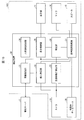
表示装置103は、図3に示す表示装置101に対して、情報の音声による出力を行うための音声認識処理部(音声認識処理部、発話部)27、音声認識データベース28が新たに追加されている。
音声認識処理部27は、特定部26によって特定された情報を音声データに変換し、変換した音声データをスピーカ15に送る。スピーカ15からは、音声により情報が出力される。
音声認識処理部27は、表示制御部25が表示部11の表示面11aに表示されている情報を音声データとしてスピーカ15に出力する。ここで、音声認識処理部27は、表示面11aに情報を表示するタイミングに合わせて音声データをスピーカ15に出力するか、あるいは表示面11aに情報を表示するタイミングよりも遅いタイミングで音声データをスピーカ15に出力する。
音声認識処理部27は、情報を音声で出力するための処理を行うだけでなく、マイク14から入力される音声データを認識し、認識した音声データに対応するコマンドを特定部26に出力する。コマンドは、音声認識データベース28において、音声データに対応付けられて格納されている。ここで、コマンドは情報を選択するためのコマンドである。つまり、マイク14から入力された音声データを認識し、認識した音声データに対応するコマンドを音声認識データベース28から読み出して、特定部26に送ることで、当該特定部26は、送られたコマンドに対応する情報を選択する。なお、音声認識処理部27と音声認識データベース28は、いずれかまたは両方がインターネット等のネットワークに接続することで参照できるように構成してもよい。
図9に示す表示装置103は、特定部26によって選択する情報の取得先は、管理サーバ2である。前記実施形態1と同様に、情報の取得先は、図10に示すように、管理情報記憶部3を用いた表示装置104であってもよい。
(情報発話までの処理)
図11は、表示装置103(104)の前に人物の鏡像が映し出され状態を示す図であり、情報が取得された後もこの状態(情報が表示されず、鏡像16のみが表示されている状態)である。この点が前記実施形態1の図1と異なる点である。
図11は、表示装置103(104)の前に人物の鏡像が映し出され状態を示す図であり、情報が取得された後もこの状態(情報が表示されず、鏡像16のみが表示されている状態)である。この点が前記実施形態1の図1と異なる点である。
情報が発話される前の処理の流れについて、図12に示すフローチャートを参照しながら以下に説明する。
まず、個人の特定を行う(ステップS31)。ここでは、制御装置20の個人特定部22によって、表示装置103の前に居る人物を特定する。個人の特定方法については、前記実施形態1と同様の方法で行うため、詳細な説明は省略する。
続いて、個人に合わせた情報の取得を行う(ステップS32)。ここでは、制御装置20の情報取得部21によって、表示装置103の前に居る人物に合わせた情報を、管理サーバ2から取得する。
最後に、取得した情報の音声出力を行う(ステップS33)。ここでは、制御装置20の音声認識処理部27によって、ステップS32において取得した情報を音声データに変換して、スピーカ15から発話する。
このように、情報を表示する代わりに発話することで、鏡像16と情報との重なりを考慮するための処理を行う必要がなくなる。また、ユーザは、鏡像16に集中することができるため、本来の目的を達成しながら、必要な情報を聞くことができる。
(表示された情報の処理)
続いて、図11に示すように、鏡像16が表示された状態で、鏡像16に対応する人物による情報の選択処理について、図13に示すフローチャートおよび図14を参照しながら以下に説明する。ここでは、人物の音声による情報の選択処理について説明する。
続いて、図11に示すように、鏡像16が表示された状態で、鏡像16に対応する人物による情報の選択処理について、図13に示すフローチャートおよび図14を参照しながら以下に説明する。ここでは、人物の音声による情報の選択処理について説明する。
まず、表示装置103の前に居る人物の音声指示の認識を行う(ステップS41)。ここでは、音声認識処理部27によって、表示装置101の前に居る人物がマイク14に向かって発話した音声データから、音声指示の内容を認識する。この内容は、情報の選択指示である。
次に、認識された指示により情報を表示する(ステップS42)。ここでは、音声認識処理部27によって認識された音声指示の内容を受け取った特定部26によって選択された情報を表示部11の表示面11aに表示する。この情報表示に伴って、鏡像16をカメラ13により撮影された撮影映像16’に変換して、撮影映像16’を情報の表示位置と異なる位置に表示する。
続いて、表示装置103の前に居る人物の目線移動先検出を行う(ステップS43)。ここでは、目線移動先検出部23によって、表示装置103の前に居る人物の眼球の角膜反射像から、目線移動先を検出する。
次に、検出された目線移動先での目線が同じ位置で所定時間経過か否かを判定する(ステップS44)。ここでは、特定部26によって、検出された目線移動先が移動しない時間(人物が注視している時間)が所定時間経過したか否かを判定する。所定時間経過せずに、目線移動先が移動した場合(ステップS44のNo)には、再度ステップS43にて、目線移動先検出部23による目線移動先検出を行う。一方、所定時間経過した場合(ステップS44のYes)には、人物がある映像を選択したとみなして、ステップS45に移行して、表示制御部25は、特定部26によって特定した映像の表示領域を、鏡像16の表示領域と交換する。
例えば図14の(a)に示すように、表示部11に鏡像16のみが表示された状態であり、個人が特定され、情報の取得が終わった状態から、鏡像16に対応する人物、すなわち表示装置103の前に居る人物が「交通情報」とマイク14に向かって発話すると、図14の(b)に示すように、交通情報を示す映像17が鏡像16の表示位置に表示され、代わりに、表示装置103の前に居る人物をカメラ13で撮影した撮影映像16’が、映像17の表示位置と異なる位置に表示される。他の情報を表示させる場合も同様の操作を行う。
図14の(b)の状態で、表示装置103の前に居る人物の目線移動先を撮影映像16’に移動させて、所定時間経過すると、再び、図14の(a)に示すように、鏡像16が表示される。
上記の処理を繰り返すことで、表示装置103の前に居る人物は、自分の姿を確認しながら、必要な情報を見やすい位置で確認することができる。
本実施形態では、表示部11の表示面11aに表示された情報を、音声コマンドにより選択し、表示装置103、104を発話させる例について説明したが、以下の実施形態3では、表示装置の前に居る人物に対して、表示装置側から発話する例について説明する。
〔実施形態3〕
本発明の他の実施形態について説明すれば、以下のとおりである。なお、説明の便宜上、前記実施形態にて説明した部材と同じ機能を有する部材については、同じ符号を付記し、その説明を省略する。
本発明の他の実施形態について説明すれば、以下のとおりである。なお、説明の便宜上、前記実施形態にて説明した部材と同じ機能を有する部材については、同じ符号を付記し、その説明を省略する。
(表示装置の詳細)
図15は、本実施形態に係る表示装置105の概略を示すブロック図である。
図15は、本実施形態に係る表示装置105の概略を示すブロック図である。
表示装置105は、前記実施形態2の図9に示す表示装置103とほぼ同じであり、音声認識データベース28の代わりに、発話用データベース29を備えている点で異なる。
本実施形態では、表示装置105の前に人物が立つことをトリガにして、当該人物に表示装置105から発話する点について説明する。具体的には、個人特定部22によって表示装置105の前に居る人物を特定することで、特定した人物に合わせた内容(人物に応じてカスタマイズされた情報)を表示装置105のスピーカ15から発話する。
発話用データベース29には、前記実施形態2で説明した音声データに対応するコマンドが対応付けられて格納されているだけでなく、表示装置105の前に居る人物を特定した状態で、特定した人物に対して発話する発話内容が格納されている。例えば洗面台に設置された表示装置103の場合、時間が7時であれば、表示装置103の前に居る特定された人物に対して「おはようございます。天気は晴れです。」をスピーカ15から発話するようにする。この発話内容は、表示装置103の設置場所、時間、特定された人物等に合わせて、変更できるように、データベース化して発話用データベース29に格納しておく。
また、表示装置105から発話するのではなく、当該表示装置105の前に居る人物が発話した内容に返答するようにしてもよい。例えば、表示装置105の前に居る人物が、「今日の天気は?」と発話すると、この発話内容に対応する「今日は晴れです」という返答を当該表示装置103からスピーカ15から発話するようにしてもよい。この場合、音声認識処理部27は、情報取得部21が取得した天気予報に関する情報を参照することで、「今日は晴れです」という返答を行っている。
なお、表示装置105においても、表示装置103と同様に、特定した個人に合わせた情報を表示部11の表示面11aに表示しているが、これら情報の表示の前に、表示装置105の前に居る人物に対して発話したり、人物から発話したりしてもよい。
(情報表示の前に発話処理の一例)
図16の(a)は、発話前の鏡像を表示した例を示し、図16の(b)は、(a)の鏡像に過去の撮影映像を重ね合わせて表示した例を示している。なお、管理サーバ2には、各個人を撮影した映像を日時に対応付けて保存しており、指定された日時の個人の撮影映像を表示装置105に送信する。
図16の(a)は、発話前の鏡像を表示した例を示し、図16の(b)は、(a)の鏡像に過去の撮影映像を重ね合わせて表示した例を示している。なお、管理サーバ2には、各個人を撮影した映像を日時に対応付けて保存しており、指定された日時の個人の撮影映像を表示装置105に送信する。
表示装置105は、図16の(a)に示すように、人物が表示部11の前に来ると、個人特定部22によって人物が特定され、このタイミングで、音声認識処理部27によって「最近ふとった?」という内容の音声データがスピーカ15を経て当該人物に「最近ふとった?」と発話する。
これに対して、上記人物が「そうかな?」とマイク14に向かって発話すると、音声認識処理部27は、上記マイク14から「そうかな?」という音声データを受け取り、この音声データに対応するコマンドを発話用データベース29から読み出し、読み出したコマンドを情報取得部21に出力する。情報取得部21は、上記コマンドから管理サーバ2に管理されている当該人物の過去の撮影映像を読み出し、過去の撮影映像を表示制御部25に出力して、表示部11において鏡像16に重ねて表示させる。図16の(b)は、現在の鏡像16に、読み出した過去の撮影映像116を重ねた状態を示す図である。ここで、鏡像16と比較するために読み出す撮影映像116は、現在から1ヶ月以上前の撮影映像であるのが好ましい。これは、1日や2日で体型はそれほど変化しないが、1ヶ月前、あるいはそれ以上前であれば、体型が変化している可能性が高いためである。
また、読み出す過去の撮影映像116は、1時点のものだけでなく、複数の時点(例えば1ヶ月前、3ヶ月前、6ヶ月前、1年前)の撮影映像116を重ねてもよいし、鏡像16と重ならない表示面11aの位置に並べて表示するようにしてもよい。これにより、鏡像16の本人が、過去の自分の撮影映像から自分の体型が変化している様子を容易に確認できる。
以下の実施形態4では、さらに、表示装置105の前に居る人物を特定し、特定した人物の撮影映像から、当該人物の状態、例えば髪型、表情、服の色、帽子の有無等を検出して、この個人の状態に応じた情報を提供する例について説明する。
〔実施形態4〕
本発明の他の実施形態について説明すれば、以下のとおりである。なお、本実施形態に係る表示装置として、前記実施形態1の表示装置101(102)、実施形態2の表示装置103(104)の何れも用いることができるため、表示装置101を例に説明する。
本発明の他の実施形態について説明すれば、以下のとおりである。なお、本実施形態に係る表示装置として、前記実施形態1の表示装置101(102)、実施形態2の表示装置103(104)の何れも用いることができるため、表示装置101を例に説明する。
(特定された個人の状態検出の一例)
図2に示す個人特定部22は、表示装置101の前に居る人物の特定が完了した時点で、さらに、個人の特定に用いたカメラ13の撮影映像から、当該人物の状態を検出する。ここで人物の状態とは、上述したように、髪型、顔の表情、服の色、帽子の有無等である。
図2に示す個人特定部22は、表示装置101の前に居る人物の特定が完了した時点で、さらに、個人の特定に用いたカメラ13の撮影映像から、当該人物の状態を検出する。ここで人物の状態とは、上述したように、髪型、顔の表情、服の色、帽子の有無等である。
例えば人物の髪型を検出する場合、表示装置101の前の人物に回転してもらい、図17の(a)に示す正面の鏡像16を映し出したときにカメラ13によって撮影し、図17の(b)に示す背面の鏡像16を映し出したときにカメラ13によって撮影する。ここで、人物の正面、背面の判断は、画像認識により実行している。画像認識の結果、顔があれば、正面、顔がなければ、背面であるというように判断している。
このように、表示装置101の前に居る人物が回転して得られた撮影映像(正面、背面)から、当該人物の髪型を検出する。これにより、検出した髪型から、人物の髪の乱れの有無を当該人物に知らせることができる。髪の正面については実際に見て判断できるが、髪の後ろは自分で確認し難いため、上記のような報知は有効である。
この報知方法としては、表示部11の表示面11aの鏡像16と重ならない位置、例えば映像領域11cに「髪の状態」として表示してもよいし、あるいは、前記実施形態2や3と同様に、髪の状態として、例えば「後ろ髪が乱れています」と音声で報知するようにしてもよい。
また、特定された個人の状態として、顔の表情、服の色、帽子の有無等についても個人特定部22によって検出され、「髪の状態」の報知と同様の方法によって、人物に報知するようにすればよい。
(個人の状態に応じた情報の提示)
特定された個人の状態が検出されれば、検出された状態に合わせた情報を、表示部11の前に居る人物に提示するようにしてもよい。
特定された個人の状態が検出されれば、検出された状態に合わせた情報を、表示部11の前に居る人物に提示するようにしてもよい。
例えば、特定された個人の状態として顔の表情が検出された場合、顔の表情から疲れの度合いを示す情報を上記人物に提示するようにしてもよい。この場合、顔の映像を解析することで、肌の張りやたるみ、しわや、目の下のくまの有無などを総合的に判断して、疲れ度合いを算出する。
また、特定された個人の状態として服の色が検出された場合、検出した服の色から連想される情報を上記人物に提示するようにしてもよい。この場合の連想される情報としては、例えば服の色に基づいた占いを挙げることができる。
さらに、特定された個人の状態として服の色、帽子の有無が検出されたとき、服の色と、帽子の有無とにおけるコーディネートが適切であるか否かを示すアドバイス情報を上記人物に提示するようにしてもよい。
また、特定された個人の状態として帽子の無が検出されたとき、当日の天気予報から、日差しが強く、紫外線量も多いと予測されるときには、その旨を伝えるとともに、帽子を被るように指示する情報を上記人物に提示するようにしてもよい。
以上の各実施形態において、表示装置101~105では、ミラー機能を実現するための手段としてハーフミラー12を用いているが、ミラー機能を実現するための手段としてはハーフミラー12に限定されるものではない。ハーフミラー12は、光の透過率と光の反射率とが等しいが、光の透過率と光の反射率とが異なる光透過反射部材であってもよい。
〔ソフトウェアによる実現例〕
表示装置101~105の制御ブロック(制御装置20)は、集積回路(ICチップ)等に形成された論理回路(ハードウェア)によって実現してもよいし、CPU(Central Processing Unit)を用いてソフトウェアによって実現してもよい。
表示装置101~105の制御ブロック(制御装置20)は、集積回路(ICチップ)等に形成された論理回路(ハードウェア)によって実現してもよいし、CPU(Central Processing Unit)を用いてソフトウェアによって実現してもよい。
後者の場合、制御装置20は、各機能を実現するソフトウェアであるプログラムの命令を実行するCPU、上記プログラムおよび各種データがコンピュータ(またはCPU)で読み取り可能に記録されたROM(Read Only Memory)または記憶装置(これらを「記録媒体」と称する)、上記プログラムを展開するRAM(Random Access Memory)などを備えている。そして、コンピュータ(またはCPU)が上記プログラムを上記記録媒体から読み取って実行することにより、本発明の目的が達成される。上記記録媒体としては、「一時的でない有形の媒体」、例えば、テープ、ディスク、カード、半導体メモリ、プログラマブルな論理回路などを用いることができる。また、上記プログラムは、該プログラムを伝送可能な任意の伝送媒体(通信ネットワークや放送波等)を介して上記コンピュータに供給されてもよい。なお、本発明は、上記プログラムが電子的な伝送によって具現化された、搬送波に埋め込まれたデータ信号の形態でも実現され得る。
〔まとめ〕
本発明の態様1に係る表示装置は、光の一部が透過し、一部が反射する光透過反射部材(ハーフミラー12)を、表示部11の表示面11a上に重ねて配置した表示装置において、上記光透過反射部材(ハーフミラー12)を透過した人物の像16が上記表示面11aに表示される領域(人物領域11b)を検出する領域検出部(人物領域検出部24)と、上記人物を特定する人物特定部(個人特定部22)と、表示装置の設置場所と対応付けられた情報から、上記人物特定部(個人特定部22)によって特定された人物に応じて生成された情報を、カスタマイズ情報として取得する情報取得部(情報取得部21)と、上記情報取得部(情報取得部21)によって取得されたカスタマイズ情報を、上記表示面11aにおける、上記領域検出部(人物領域検出部24)によって検出された領域(人物領域11b)と異なる領域(映像領域11c)に表示させる表示制御部25と、を備えることを特徴としている。
本発明の態様1に係る表示装置は、光の一部が透過し、一部が反射する光透過反射部材(ハーフミラー12)を、表示部11の表示面11a上に重ねて配置した表示装置において、上記光透過反射部材(ハーフミラー12)を透過した人物の像16が上記表示面11aに表示される領域(人物領域11b)を検出する領域検出部(人物領域検出部24)と、上記人物を特定する人物特定部(個人特定部22)と、表示装置の設置場所と対応付けられた情報から、上記人物特定部(個人特定部22)によって特定された人物に応じて生成された情報を、カスタマイズ情報として取得する情報取得部(情報取得部21)と、上記情報取得部(情報取得部21)によって取得されたカスタマイズ情報を、上記表示面11aにおける、上記領域検出部(人物領域検出部24)によって検出された領域(人物領域11b)と異なる領域(映像領域11c)に表示させる表示制御部25と、を備えることを特徴としている。
上記の構成によれば、表示制御部25によって、表示装置の設置場所と対応付けられた情報から、人物に応じて生成された情報を、カスタマイズ情報として取得し、取得したカスタマイズ情報を、表示面における、光透過反射部材を透過した人物の像が表示される領域と異なる領域に表示させることで、表示装置の前に居るユーザは、光透過反射部材に映された自分の鏡像を確認しながら、カスタマイズ情報を確認することが可能となる。
ここで、カスタマイズ情報とは、ミラー機能付き表示装置の設置場所(洗面台、鏡台、姿見、玄関、お風呂場等の家庭内でミラー機能付き表示装置の設置が想定される場所)毎に紐付けられた各種情報をいう。例えば、設置場所の一つである洗面台に紐付けられた情報として、利用時間・利用シーン、鏡像、鏡の前に居る時間を考慮したニュース、天気予報、交通情報、占い、メールなどの情報を挙げることができる。
従って、上記構成の表示装置によれば、表示装置の設置場所を考慮し、表示装置の前に居る人物に対して必要な情報を適切なタイミングで取得できるので、ユーザが表示装置の前に立つだけで、ユーザにとって必要な情報を適切なタイミングで取得して表示させることができるという効果を奏する。
本発明の態様2に係る表示装置は、上記態様1において、上記表示制御部25は、上記情報取得部21によって取得されたカスタマイズ情報を、上記表示面11aにおける、上記領域検出部(人物領域検出部24)によって検出された領域(人物領域11b)に重ならない領域(映像領域11c)に表示させることが好ましい。
上記構成によれば、上記情報取得部によって取得された個人に合わせた情報を、上記表示部の表示面における、上記人物の鏡像に重ならない位置に表示させることで、個人に合わせた情報と鏡像とが確実に分離して表示されることになる。これにより、表示部に表示された個人に合わせた情報の確認がしやすくなる。
本発明の態様3に係る表示装置は、上記態様1または2において、ユーザに指定されたカスタマイズ情報を特定する特定部26を備え、上記表示制御部25は、上記特定部26によって特定されたカスタマイズ情報を、上記表示面11aにおける上記人物領域(表示部11)に表示させてもよい。
上記の構成によれば、個人に合わせた情報のうち、選択された情報を、人物の鏡像の表示位置に表示させることで、ユーザは、必要な情報を容易に確認することができる。
本発明の態様4に係る表示装置は、上記態様3において、上記人物特定部(個人特定部22)によって特定された人物を、上記光透過反射部材(ハーフミラー12)側から撮影する第1撮影部(カメラ13)を備え、上記表示制御部25は、上記特定部26によって特定されたと判定されたカスタマイズ情報を、上記領域検出部(人物領域検出部24)によって検出された領域(人物領域11b)に表示させるとともに、上記第1撮影部(カメラ13)によって撮影された人物の映像を、上記表示面11aにおける、上記領域検出部(人物領域検出部24)によって検出された領域(人物領域11b)以外の領域に表示させてもよい。
上記の構成によれば、個人に応じたカスタマイズ情報のうち、特定されたカスタマイズ情報が、人物の鏡像が表示されていた領域に表示されることで、当該特定されたカスタマイズ情報がユーザにとって見やすい位置に表示されることになる。さらに、元の個人の鏡像が撮影映像として選択された情報の表示位置と異なる位置に表示されるので、選択された情報を確認しながら、自分の撮影映像も見ることができる。
本発明の態様5に係る表示装置は、上記態様3または4において、上記人物特定部(個人特定部22)によって特定された人物の目線の移動先を検出する目線移動先検出部23をさらに備え、上記特定部26は、上記目線移動先検出部23によって検出された人物の目線の移動先が、上記表示面11aに表示されたカスタマイズ情報の一つであるとき、当該カスタマイズ情報が特定されたと判定し、上記表示制御部25は、上記特定部26によって特定されたと判定されたカスタマイズ情報を、上記表示面11aにおける、上記領域検出部(人物領域検出部24)によって検出された領域(人物領域11b)に表示させてもよい。
上記構成によれば、表示装置の前に居る人物の目線の移動先を検出することで、表示部11に表示された個人に応じたカスタマイズ情報の何れかが特定されていることが判定することができる。つまり、ユーザは、自分の鏡像を確認しながら、目線を移動させるだけで、自分に合わせた情報を特定し、当該情報を確認することができる。
本発明の態様6に係る表示装置は、上記態様1~5の何れか1態様において、上記光透過反射部材(ハーフミラー12)の前に居る人物を撮影する第2撮影部(カメラ13)をさらに備え、上記人物特定部(個人特定部22)は、上記第2撮影部(カメラ13)によって撮影された人物の撮影映像から、人物を特定してもよい。
これにより、表示装置に搭載されているカメラで個人の特定を行うことが可能となる。
本発明の態様7に係る表示装置は、上記態様1~5の何れか1態様において、上記人物特定部(個人特定部22)は、人物を特定する情報を格納したウェアラブル装置から取得した情報によって人物を特定することが好ましい。
これにより、個人の特定にウェアラブル装置が使用されることで、撮影映像による個人の特定よりも確実に個人を特定することができる。
本発明の態様8に係る表示装置は、光の一部が透過し、一部が反射する光透過反射部材(ハーフミラー12)を、表示部11の表示面11a上に重ねて配置した表示装置において、上記光透過反射部材(ハーフミラー12)の光反射面側に存在する人物を特定する人物特定部(個人特定部22)と、表示装置の設置場所と対応付けられた情報から、上記人物特定部(個人特定部22)によって特定された人物に応じて生成された情報を、カスタマイズ情報として取得する情報取得部21と、上記情報取得部21によって取得されたカスタマイズ情報を、音声で出力する発話部(音声認識処理部27)と、備えていることを特徴としている。
上記の構成によれば、発話部によって、情報取得部によって取得されたカスタマイズ情報を音声で出力することで、光透過反射部材の前に居るユーザは、光透過反射部材に映された自分の鏡像を確認しながら、自分に合わせたカスタマイズ情報を耳で確認することが可能となる。
ここで、カスタマイズ情報とは、ミラー機能付き表示装置の設置場所(洗面台、鏡台、姿見、玄関、お風呂場等の家庭内でミラー機能付き表示装置の設置が想定される場所)毎に紐付けられた各種情報をいう。例えば、設置場所の一つである洗面台に紐付けられた情報として、利用時間・利用シーン、鏡像、鏡の前に居る時間を考慮したニュース、天気予報、交通情報、占い、メールなどの情報を挙げることができる。
従って、上記構成の表示装置によれば、表示装置の設置場所を考慮し、表示装置の前に居る人物に対して必要な情報を適切なタイミングで取得できるので、ユーザが表示装置の前に立つだけで、ユーザにとって必要な情報を適切なタイミングで音声出力することができるという効果を奏する。
本発明の態様9に係る表示装置は、上記態様8において、さらに、上記情報取得部21によって取得されたカスタマイズ情報を、上記表示面11aに表示させる表示制御部25を備えていることが好ましい。
本発明の態様10に係る表示装置は、上記態様8または9において、上記発話部は、上記カスタマイズ情報が上記表示面11aに表示される前に、当該カスタマイズ情報を音声で出力してもよい。
本発明の態様11に係る表示装置は、上記態様9または10において、光透過反射部材(ハーフミラー12)を透過した人物の像が上記表示面11aに表示される人物領域11bを検出する人物領域検出部24を備え、上記表示制御部25は、上記情報取得部21によって取得されたカスタマイズ情報を、上記表示面11aにおける上記人物領域11bに重ならない領域に表示させてもよい。
上記構成によれば、上記情報取得部21によって取得されたカスタマイズ情報を、上記表示部11の表示面11aにおける、上記人物領域11bに重ならない位置に表示させることで、カスタマイズ情報と人物の像とが確実に分離して表示されることになる。これにより、表示部11に表示されたカスタマイズ情報の確認がしやすくなる。
本発明の態様12に係る表示装置は、上記態様11において、ユーザに指定されたカスタマイズ情報を特定する特定部26を備え、上記表示制御部25は、上記特定部26によって特定されたカスタマイズ情報を、上記表示面11aにおける上記人物領域11bに表示させてもよい。
本発明の態様13に係る表示装置は、上記態様12において、上記特定部26は、上記人物特定部26によって特定された人物の発する音声により、上記表示面に表示されたカスタマイズ情報の一つを選択してもよい。
上記の構成によれば、音声を発するだけで、特定された個人は、所望する情報を適切に選択することができる。つまり、ユーザは、自分の鏡像を確認しながら、音声を発するだけで、カスタマイズ情報を選択し、当該情報を確認することができる。
本発明の態様14に係る表示装置は、上記態様8~13の何れか1態様において、上記光透過反射部材の光反射面側に存在する人物を撮影する撮影部をさらに備え、上記人物特定部26は、上記撮影部によって撮影された人物の映像から、人物を特定してもよい。
これにより、表示装置に搭載されているカメラで個人の特定を行うことが可能となる。
本発明の態様15に係る表示装置は、上記態様8~13の何れか1態様において、上記人物特定部26は、人物を特定する人物情報を格納したウェアラブル装置から取得した当該人物情報によって人物を特定してもよい。
これにより、個人の特定にウェアラブル装置が使用されることで、撮影映像による個人の特定よりも確実に個人を特定することができる。
本発明の態様16に係る表示装置は、上記態様1~15の何れか1態様において、上記情報取得部21は、上記カスタマイズ情報を管理している管理サーバ2から、通信ネットワークを介して、人物に応じたカスタマイズ情報を取得するのが好ましい。
これにより、同一の管理サーバ2に接続されている表示装置同士は、同一の情報を共有することができるので、ユーザは、同一管理サーバ2に接続されている表示装置であれば、どの表示装置を利用しても同じ情報を得ることができる。
従って、同一の管理サーバ2に接続されている表示装置を、例えば家庭内において、ユーザが起床して出勤するまでの間に使用するであろう、洗面台、鏡台、姿に、玄関に表示装置を設置すれば、ユーザは、起床して出勤するまでの間に同じ情報を確認し続けることができる。
本発明は上述した各実施形態に限定されるものではなく、請求項に示した範囲で種々の変更が可能であり、異なる実施形態にそれぞれ開示された技術的手段を適宜組み合わせて得られる実施形態についても本発明の技術的範囲に含まれる。さらに、各実施形態にそれぞれ開示された技術的手段を組み合わせることにより、新しい技術的特徴を形成することができる。
本発明は、鏡としてのユーザの使用目的や使用時間が異なる場所に設置されるミラー機能付きの表示装置、特に家庭内の各場所に設置されるミラー機能付き表示装置に利用することができる。
2 管理サーバ
3 管理情報記憶部
11 表示部
11a 表示面
11b 人物領域
11c 映像領域
12 ハーフミラー(光透過反射部材)
13 カメラ(第1撮影部、第2撮影部)
14 マイク
15 スピーカ(発話部)
16 鏡像
16’ 撮影映像
17 映像(情報)
18 リング
20 制御装置
21 情報取得部
22 個人特定部(人物特定部)
23 目線移動先検出部
24 人物領域検出部(領域検出部)
25 表示制御部
26 特定部
27 音声認識処理部(音声認識処理部、発話部)
28 音声認識データベース
29 発話用データベース
101~105 表示装置
116 撮影映像
3 管理情報記憶部
11 表示部
11a 表示面
11b 人物領域
11c 映像領域
12 ハーフミラー(光透過反射部材)
13 カメラ(第1撮影部、第2撮影部)
14 マイク
15 スピーカ(発話部)
16 鏡像
16’ 撮影映像
17 映像(情報)
18 リング
20 制御装置
21 情報取得部
22 個人特定部(人物特定部)
23 目線移動先検出部
24 人物領域検出部(領域検出部)
25 表示制御部
26 特定部
27 音声認識処理部(音声認識処理部、発話部)
28 音声認識データベース
29 発話用データベース
101~105 表示装置
116 撮影映像
Claims (9)
- 光の一部が透過し、一部が反射する光透過反射部材を、表示部の表示面上に重ねて配置した表示装置において、
上記光透過反射部材を透過した人物の像が上記表示面に表示される人物領域を検出する領域検出部と、
上記人物を特定する人物特定部と、
表示装置の設置場所と対応付けられた情報から、上記人物特定部によって特定された人物に応じて生成された情報を、カスタマイズ情報として取得する情報取得部と、
上記情報取得部によって取得されたカスタマイズ情報を、上記表示面における、上記領域検出部によって検出された人物領域と異なる領域に表示させる表示制御部と、
を備えることを特徴とする表示装置。 - 上記表示制御部は、
上記情報取得部によって取得されたカスタマイズ情報を、上記表示面における上記人物領域に重ならない領域に表示させることを特徴とする請求項1に記載の表示装置。 - ユーザに指定されたカスタマイズ情報を特定する特定部を備え、
上記表示制御部は、
上記特定部によって特定されたカスタマイズ情報を、上記表示面における上記人物領域に表示させることを特徴とする請求項1または2に記載の表示装置。 - 上記人物特定部によって特定された人物の目線の移動先を検出する目線移動先検出部をさらに備え、
上記特定部は、
上記目線移動先検出部によって検出された人物の目線の移動先に表示されたカスタマイズ情報を特定し、
上記表示制御部は、
上記特定部によって特定されたカスタマイズ情報を、上記表示面における上記人物領域に表示させることを特徴とする請求項3に記載の表示装置。 - 光の一部が透過し、一部が反射する光透過反射部材を、表示部の表示面上に重ねて配置した表示装置において、
上記光透過反射部材の光反射面側に存在する人物を特定する人物特定部と、
表示装置の設置場所と対応付けられた情報から、上記人物特定部によって特定された人物に応じて生成された情報を、カスタマイズ情報として取得する情報取得部と、
上記情報取得部によって取得されたカスタマイズ情報を、音声で出力する発話部と、
を備えていることを特徴とする表示装置。 - さらに、上記情報取得部によって取得されたカスタマイズ情報を、上記表示面に表示させる表示制御部を備えていることを特徴とする請求項5に記載の表示装置。
- 上記発話部は、
上記カスタマイズ情報が上記表示面に表示される前に、当該カスタマイズ情報を音声で出力することを特徴とする請求項6に記載の表示装置。 - 上記人物特定部は、
人物を特定する人物情報を格納したウェアラブル装置から取得した当該人物情報によって人物を特定することを特徴とする請求項5~7の何れか1項に記載の表示装置。 - 上記情報取得部は、
上記カスタマイズ情報を管理する管理サーバから、通信ネットワークを介して、人物に応じたカスタマイズ情報を取得することを特徴とする請求項1~8の何れか1項に記載の表示装置。
Applications Claiming Priority (4)
| Application Number | Priority Date | Filing Date | Title |
|---|---|---|---|
| JP2014094204A JP6541940B2 (ja) | 2014-04-30 | 2014-04-30 | 表示装置 |
| JP2014-094204 | 2014-04-30 | ||
| JP2014-094206 | 2014-04-30 | ||
| JP2014094206A JP2015210797A (ja) | 2014-04-30 | 2014-04-30 | 表示装置 |
Publications (1)
| Publication Number | Publication Date |
|---|---|
| WO2015166691A1 true WO2015166691A1 (ja) | 2015-11-05 |
Family
ID=54358432
Family Applications (1)
| Application Number | Title | Priority Date | Filing Date |
|---|---|---|---|
| PCT/JP2015/054590 Ceased WO2015166691A1 (ja) | 2014-04-30 | 2015-02-19 | 表示装置 |
Country Status (1)
| Country | Link |
|---|---|
| WO (1) | WO2015166691A1 (ja) |
Citations (6)
| Publication number | Priority date | Publication date | Assignee | Title |
|---|---|---|---|---|
| JPH11197116A (ja) * | 1998-01-08 | 1999-07-27 | Mitsubishi Electric Corp | 健康管理装置 |
| JP2009053328A (ja) * | 2007-08-24 | 2009-03-12 | Nec Corp | 画像表示装置 |
| JP2010004118A (ja) * | 2008-06-18 | 2010-01-07 | Olympus Corp | デジタルフォトフレーム、情報処理システム、制御方法、プログラム及び情報記憶媒体 |
| JP2010087755A (ja) * | 2008-09-30 | 2010-04-15 | Kddi Corp | 視聴制限方法およびシステム |
| WO2013084395A1 (ja) * | 2011-12-07 | 2013-06-13 | 株式会社ニコン | 電子機器、情報処理方法およびプログラム |
| JP2013246184A (ja) * | 2012-05-23 | 2013-12-09 | Sharp Corp | 表示装置 |
-
2015
- 2015-02-19 WO PCT/JP2015/054590 patent/WO2015166691A1/ja not_active Ceased
Patent Citations (6)
| Publication number | Priority date | Publication date | Assignee | Title |
|---|---|---|---|---|
| JPH11197116A (ja) * | 1998-01-08 | 1999-07-27 | Mitsubishi Electric Corp | 健康管理装置 |
| JP2009053328A (ja) * | 2007-08-24 | 2009-03-12 | Nec Corp | 画像表示装置 |
| JP2010004118A (ja) * | 2008-06-18 | 2010-01-07 | Olympus Corp | デジタルフォトフレーム、情報処理システム、制御方法、プログラム及び情報記憶媒体 |
| JP2010087755A (ja) * | 2008-09-30 | 2010-04-15 | Kddi Corp | 視聴制限方法およびシステム |
| WO2013084395A1 (ja) * | 2011-12-07 | 2013-06-13 | 株式会社ニコン | 電子機器、情報処理方法およびプログラム |
| JP2013246184A (ja) * | 2012-05-23 | 2013-12-09 | Sharp Corp | 表示装置 |
Similar Documents
| Publication | Publication Date | Title |
|---|---|---|
| US20250264722A1 (en) | Display System | |
| JP2015210797A (ja) | 表示装置 | |
| CN112181152B (zh) | 基于mr眼镜的广告推送管理方法、设备及应用 | |
| CN113383295B (zh) | 调节数字内容以激发更大的瞳孔半径响应的生物反馈方法 | |
| US10386637B2 (en) | Information display terminal, information display system, and information display method | |
| US11194535B2 (en) | Information processing apparatus, information processing system, and non-transitory computer readable medium storing program | |
| WO2016158792A1 (ja) | 情報処理装置、制御方法、およびプログラム | |
| JP2012146216A (ja) | 電子機器および電子機器の制御プログラム | |
| JP5771998B2 (ja) | 電子機器および電子機器の制御プログラム | |
| US20180150722A1 (en) | Photo synthesizing method, device, and medium | |
| JP2016021259A (ja) | 電子機器および電子機器の制御プログラム | |
| US20260118956A1 (en) | Retinal Reflection Tracking For Gaze Alignment | |
| JP2016161835A (ja) | 表示装置、制御プログラム、および制御方法 | |
| JP6316648B2 (ja) | 表示装置 | |
| JP6541940B2 (ja) | 表示装置 | |
| US20240319789A1 (en) | User interactions and eye tracking with text embedded elements | |
| WO2015166691A1 (ja) | 表示装置 | |
| JP2012146208A (ja) | 電子機器および電子機器の制御プログラム | |
| JP5771999B2 (ja) | 電子機器および電子機器の制御プログラム | |
| JP5811537B2 (ja) | 電子機器 | |
| JP2019023872A (ja) | 電子機器 | |
| JP2012146219A (ja) | 電子機器および電子機器の制御プログラム | |
| US20240221301A1 (en) | Extended reality assistance based on user understanding | |
| US12394299B2 (en) | User suggestions based on engagement | |
| KR102957608B1 (ko) | 외부 웨어러블 전자 장치로부터 정보를 수신하는 웨어러블 전자 장치 및 그 작동 방법 |
Legal Events
| Date | Code | Title | Description |
|---|---|---|---|
| 121 | Ep: the epo has been informed by wipo that ep was designated in this application |
Ref document number: 15786039 Country of ref document: EP Kind code of ref document: A1 |
|
| NENP | Non-entry into the national phase |
Ref country code: DE |
|
| 122 | Ep: pct application non-entry in european phase |
Ref document number: 15786039 Country of ref document: EP Kind code of ref document: A1 |