WO2015162722A1 - 映像投写装置 - Google Patents
映像投写装置 Download PDFInfo
- Publication number
- WO2015162722A1 WO2015162722A1 PCT/JP2014/061434 JP2014061434W WO2015162722A1 WO 2015162722 A1 WO2015162722 A1 WO 2015162722A1 JP 2014061434 W JP2014061434 W JP 2014061434W WO 2015162722 A1 WO2015162722 A1 WO 2015162722A1
- Authority
- WO
- WIPO (PCT)
- Prior art keywords
- sensor
- detection
- image
- image projection
- gesture
- Prior art date
- Legal status (The legal status is an assumption and is not a legal conclusion. Google has not performed a legal analysis and makes no representation as to the accuracy of the status listed.)
- Ceased
Links
Images












Classifications
-
- G—PHYSICS
- G06—COMPUTING OR CALCULATING; COUNTING
- G06F—ELECTRIC DIGITAL DATA PROCESSING
- G06F3/00—Input arrangements for transferring data to be processed into a form capable of being handled by the computer; Output arrangements for transferring data from processing unit to output unit, e.g. interface arrangements
- G06F3/01—Input arrangements or combined input and output arrangements for interaction between user and computer
-
- G—PHYSICS
- G06—COMPUTING OR CALCULATING; COUNTING
- G06F—ELECTRIC DIGITAL DATA PROCESSING
- G06F3/00—Input arrangements for transferring data to be processed into a form capable of being handled by the computer; Output arrangements for transferring data from processing unit to output unit, e.g. interface arrangements
- G06F3/01—Input arrangements or combined input and output arrangements for interaction between user and computer
- G06F3/03—Arrangements for converting the position or the displacement of a member into a coded form
- G06F3/033—Pointing devices displaced or positioned by the user, e.g. mice, trackballs, pens or joysticks; Accessories therefor
- G06F3/0346—Pointing devices displaced or positioned by the user, e.g. mice, trackballs, pens or joysticks; Accessories therefor with detection of the device orientation or free movement in a three-dimensional [3D] space, e.g. 3D mice, 6-DOF [six degrees of freedom] pointers using gyroscopes, accelerometers or tilt-sensors
-
- G—PHYSICS
- G06—COMPUTING OR CALCULATING; COUNTING
- G06F—ELECTRIC DIGITAL DATA PROCESSING
- G06F3/00—Input arrangements for transferring data to be processed into a form capable of being handled by the computer; Output arrangements for transferring data from processing unit to output unit, e.g. interface arrangements
- G06F3/01—Input arrangements or combined input and output arrangements for interaction between user and computer
- G06F3/03—Arrangements for converting the position or the displacement of a member into a coded form
- G06F3/041—Digitisers, e.g. for touch screens or touch pads, characterised by the transducing means
- G06F3/042—Digitisers, e.g. for touch screens or touch pads, characterised by the transducing means by opto-electronic means
Definitions
- the present invention relates to an image projection apparatus having a gesture detection function.
- Patent Document 1 As background art in this technical field.
- the problem is that “an operator's gesture made in a predetermined direction different from the projection direction of image light can be detected, and the operator's gesture can be detected even when the distance between the projector and the projection surface is narrow.
- an image projection apparatus that can detect and can further improve the detection sensitivity of an operator's gesture without reducing the visibility of the image projected on the projection surface.
- the image projection apparatus 1 that modulates light from a light source into image light by a light modulation element, projects image light through an imaging optical system, and displays an image on the projection surface 20.
- the gesture detection means 13 capable of detecting the gesture JS of the operator OP performed in a predetermined direction different from the projection direction D1, and detection of the gesture by the gesture detection means 13
- a detection range setting means for determining the coverage area has been described as a configuration equipped with a control signal generating means for generating a control signal based on the gesture information which is the detection result of the gesture detection means 13 ".
- the gesture detection means recognizes an operator's gesture when an object enters the detection range, and does not consider whether the object is a hand or a human body. Therefore, for example, when a person passes through the detection range, it is recognized as a gesture, and there arises a problem that control contrary to the operator's intention is performed.
- a video projector particularly in a desktop projector using a short focus lens
- the operator operates at a position close to the desk surface on which the video is projected.
- the human body of the operator on the back is often included.
- An object of the present invention is to provide an image projection device that improves gesture detection accuracy by distinguishing between the operator's hand and the human body and performs control according to the operator's intention.
- the present invention is an image projection apparatus capable of controlling an image projected based on an operator's gesture, an image projection unit that generates image light based on the image signal and projects the image on a projection surface, and an operator's gesture And an operation detection unit that generates an operation signal for controlling the projection image based on a gesture detected by the sensor, the sensor including a plurality of detection elements,
- the projection surface is an installation surface on which the video projection device is installed
- at least one predetermined detection element of the plurality of detection elements has a ratio of the projected video screen included in the detection range equal to or higher than a predetermined ratio. It is characterized by becoming.
- an image projection apparatus that performs control according to the operator's intention without erroneous detection of a gesture.
- FIG. 1 is an overview diagram of a video projection apparatus according to Embodiment 1.
- FIG. The block diagram which shows the internal structure of a video projector. The figure which shows the case where a sensor is arrange
- the figure which showed the frequency component of the signal obtained by the motion of a hand and the motion of a human body (Example 2).
- the figure which showed an example of the detection circuit structure of the sensor using a thermopile Example 3
- FIG. 10 is a diagram illustrating a gesture in the z direction (Example 4). The figure which showed the relationship between the hand and detection range at the time of z direction gesture. The figure which showed the time change of the sensor signal of each CH at the time of az direction operation
- FIG. 10 is a diagram illustrating time variation of output signals of a normal detection element and a detection element in a failure state (Example 5). The figure which showed the flowchart of failure determination of a detection element. The figure which shows the pattern of a hand gesture. The figure which shows the pattern excluded from error determination. The figure which showed the kind of gesture (Example 6).
- FIG. 1 is an overview of the image projection apparatus according to the first embodiment.
- the image projection apparatus 1 is installed on an installation surface (desk) 11, magnifies the image light generated inside the apparatus by the projection lens 4 d, reflects the image light by the reflection mirror 4 e, and projects the image screen 10 on the installation surface 11. .
- the focus of the projected image is adjusted by the focus ring 15.
- the reflection mirror 4e is configured to be foldable, and is stored so that the reflection surface faces the image projection device 1 when not in use.
- the video projection device 1 includes a sensor 2 that detects an operator's gesture. The sensor 2 detects the movement and direction of the operator's hand within the detection range 2a.
- the sensor 2 may have a light source to detect an operator's hand, or may be a passive sensor that does not have a light source.
- a pyroelectric sensor that is a temperature sensor that detects the temperature of the operator's hand can be used.
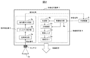
- FIG. 2 is a block diagram showing the internal configuration of the image projection apparatus 1.
- the video projection device 1 includes an operation detection unit 3 and a video projection unit 4.
- the operation detection unit 3 includes a signal detection unit 3a, a gesture determination unit 3b, and an operation signal generation unit 3c.
- the signal detection unit 3a detects the signal from the sensor 2 and supplies it to the gesture determination unit 3b.
- the gesture determination unit 3b performs processing for determining various gesture movements based on the supplied signal.
- the operation signal generation unit 3c generates an operation signal corresponding to the determination result of the gesture determination unit 3b and outputs the operation signal to an external device 6 such as a PC (Personal Computer) or a smartphone.
- the external device 6 controls the video signal supplied to the video projection device 1 according to the operation signal from the operation signal generation unit 3c.
- the operation signal is generated based on the gesture of the operator, and the image projected from the image projection apparatus 1 is controlled by the operation signal. For example, according to the direction in which the operator moves his / her hand, an operation of scrolling, frame-by-frame advancement, or switching between slides is performed.
- the external device 6 may be any device that supplies a video signal to the video projection device 1.
- a card-like storage medium inserted into a card interface provided in the video projection device 1 may be used.
- the video projection unit 4 includes a video control unit 4a, a light source unit 4b, a light control unit 4c, a projection lens 4d, and a projection mirror 4e.
- the video control unit 4a sends a control signal to the light source unit 4b and the light control unit 4c in accordance with the video signal supplied from the external device 6.
- the light source unit 4b is a light source such as a halogen lamp, an LED, or a laser, and adjusts the amount of light according to the control signal of the video control unit 4a. When the light source unit 4b includes three colors of R, G, and B, the light amount may be controlled independently according to the video signal.
- the light control unit 4c has optical system components such as a mirror, a lens, a prism, and an imager (for example, a display device such as a liquid crystal panel), and is supplied from the external device 6 using light emitted from the light source unit 4b. An optical image based on the processed image signal is generated.
- the projection lens 4d enlarges the image output from the light control unit 4c.
- the projection mirror 4 e reflects the light emitted from the projection lens 4 d and projects the video screen 10 on the installation surface 11.
- the projection mirror 4e uses an aspherical mirror, and when projecting an image screen of the same size, the projection distance can be shortened compared to a general projection apparatus.
- the projection lens 4d and the projection mirror 4e are collectively referred to as a projection optical unit.
- the installation surface (desk surface) 11 is an xz plane, and the image projection apparatus 1 is installed upright in the y direction.
- the operator is positioned in the z direction with respect to the image projection apparatus 1.
- FIG. 3 is a diagram showing a case where the sensor 2 is arranged on the upper side (y direction) of the image projection device 1.
- the detection range of the sensor 2 at this time is indicated by 2a.
- FIG. 3 shows the positional relationship between the human body 20 and the hand 21 of the operator at this time.
- FIG. 4 is a diagram showing a case where the sensor 2 is arranged on the upper side of the image projection device 1 and the detection range 2a is enlarged.
- the detection range 2a is expanded so as to include the video screen 10
- the detection can be satisfactorily detected at a position close to the video projection apparatus 1, but the detection sensitivity is lowered at the end position of the video screen 10 far from the video projection apparatus 1. Judgment becomes difficult. Therefore, it is necessary to make the detection possible at a height close to the installation surface without reducing the sensitivity to the end position of the video screen.
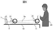
- FIG. 5 is a diagram showing a case where the sensor 2 is arranged on the lower side of the image projection device 1.
- the sensitivity does not decrease regardless of the distance from the sensor 2, so that gesture detection is possible on a video screen close to the installation surface.
- the average length of the hand is 19 cm.
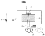
- FIG. 6 is a diagram showing an example of erroneous detection due to the movement of the human body.
- the sensor 2 recognizes the movement and direction of the human body 20 as a gesture, and erroneous detection occurs. Therefore, it is necessary to separate the gesture of the hand 21 from the movement of the human body 20.
- the following describes a configuration that can perform an intuitive operation on a video screen close to the installation surface without reducing the sensitivity at the edge of the video screen and suppress false detection. That is, the configuration of the sensor 2 for suppressing erroneous detection and the setting of the detection range 2a for separating the movement of the hand and the human body will be described.
- FIG. 7A and 7B are diagrams showing a configuration example and a detection range of the sensor 2, wherein FIG. 7A is a diagram viewed from the z direction, and FIG. 7B is a diagram viewed from the y direction and the x direction.
- the sensor 2 has a plurality (four in this case) of detection elements 16, and each of the detection elements 16 has a different detection range.
- the detection elements located in the y ′ direction, the x ′ direction, the y direction, and the x direction from the center of the sensor 2 will be referred to as CH1, CH2, CH3, and CH4, respectively.
- the sensor 2 detects a gesture using the signal amplitude from each detection element 16 and the timing of signal output. For example, when a hand is shaken in the x to x ′ direction, the CH1 and CH3 signals are detected after the CH4 signal is output, and finally the CH2 signal is detected. At this time, a time difference occurs between the signal outputs of CH4 and CH2.
- the gesture at that time is a gesture from x to the x 'direction.
- four detection elements 16 are used. However, the number of detection elements is not limited to four, and may be appropriately increased or decreased according to the movement direction of the hand gesture.
- FIG. (B) shows an example of the detection range 2a of each detection element 16 in the xz section and the yz section direction of the sensor 2.
- the detection ranges 2a of the detection elements 16 CH1 to CH4 are arranged so as to expand radially from the central axis (z direction) of the sensor 2 (x direction and y direction).
- the central axis of each CH detection range 2a does not necessarily extend radially, and the detection range 2a of each CH may be different even if it is parallel to the central axis of the sensor 2.
- a part of the detection range 2a of each CH may overlap.
- FIG. 8 is a diagram illustrating an example of setting the detection range 2a.
- At least one predetermined detection element of the detection elements 16 is set so that the video screen 10 included in the detection range 2a becomes a predetermined ratio or more.
- the ratio of the video screen 10 to the detection range 2a is referred to as “video screen occupation ratio”.
- the predetermined detection element is a detection element of CH1, and this detection element (CH1) is set so that the video screen occupation ratio is larger than that of the other elements.
- the movement of the hand on the video screen of the operator and the movement of the human body of the operator can be separated.
- the predetermined detection element whose video screen occupancy rate is equal to or higher than the predetermined value will be referred to as a “gesture monitoring element” (reference numeral 16g). 7 and 8, CH1 is the gesture monitoring element 16g.
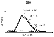
- FIG. 9 is a diagram for explaining the separation of the movement of the hand and the human body by the gesture monitoring element.
- FIG. 9 shows changes in sensor signals generated in the gesture monitoring element CH1 (16g) and the other detection elements CH3 with respect to the movement of the hand 21 and the movement of the human body 20 shown in FIG.
- the gesture monitoring element CH1 since the movement of the hand 21 crosses the detection range 2a (CH1), a large signal change occurs. However, since the movement of the human body 20 has a small ratio across the detection range 2a (CH1), the signal change is small. On the other hand, since the other detection element CH3 detects any movement of the hand 21 and the human body 20, the signal change becomes large. In this manner, the gesture monitoring element detects the movement of the operator's hand with priority over the movement of other human bodies. The movement of the hand and the human body can be separated by comparing the signal level of the gesture monitoring element with the signal level of the other detection elements.
- the video screen occupancy rate of the gesture monitoring element may be determined so as to satisfy this. .
- the video screen occupancy is about 50% or more, it is practically satisfactory.
- the gesture monitoring element 16 g is included in the sensor 2, but the gesture monitoring element may be provided separately from the sensor 2. It is assumed that the gesture monitoring element is included in the sensor 2 and the sensor 2 is tilted downward (installation surface side). At this time, the gesture monitoring element has a detection range on the video screen (installation surface). However, since the other detection elements are also directed downward, the detection sensitivity at the edge of the video screen may be reduced. On the other hand, by providing the gesture monitoring element as a separate body, there is an advantage that the degree of freedom with respect to the operability of the sensor 2 is increased and the sensitivity at the end of the video screen can be secured.
- FIG. 10 is a diagram illustrating an example in which the gesture monitoring element is configured separately from the sensor 2.
- the video projection device 1 is provided with a gesture monitoring element 17 g that is separate from the sensor 2, and the gesture monitoring element 17 g is arranged at a different position so as to detect only the video screen 10.
- a region 2b indicates a range detected by the gesture monitoring element 17g, and only the hand movement in the region 2b can be detected.
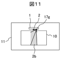
- FIG. 11 is a diagram showing an example in which the operation range by the gesture monitoring element is limited.
- the gesture monitoring element 17g configured as a separate body can not only separate the hand and the human body but also limit the operation range of the operator by limiting the detection range 2b. For example, it is possible to use such that the operation range of the operator is limited only to the center of the video screen 10.
- the limit of the operation range can be changed according to the situation. For example, when it is possible to operate at any position on the video screen, the detection range 2b is expanded to the entire video screen 10, and when it is desired to limit the operation to only the front of the video projector 1, the detection range 2b is limited to the center of the video screen. . If the area is a predetermined ratio (for example, 1/3), the operable range can be limited to 1/3. Needless to say, the operation range can be changed to the left, right, and four corners of the video screen depending on the use environment.
- the operation range may be switched from the menu screen of the image projection apparatus 1 or may be switched by a mechanical switch. Alternatively, the operation range may be switched by a gesture after enabling the operation range switching mode.
- the operation range switching mode may be enabled by a menu or may be enabled by a specific gesture.
- FIG. 12 is a diagram showing the setting of the detection range of the sensor 2 according to the application.
- (a) is a case where priority is given to suppression of erroneous detection.
- (B) shows a case where priority is given to operability.
- the center axis of the sensor 2 is attached to the image projection apparatus so as to be inclined with respect to the installation surface of the image projection apparatus.
- the height h from the installation surface 11 to the center of the sensor 2 is 2 ⁇
- the angle of the detection range 2 a of the sensor 2 is 2 ⁇
- the inclination ⁇ of the central axis of the sensor 2 with respect to the installation surface and from the sensor 2 to the edge of the video screen 10
- the total length of the hand 21 is H.
- the detection range of the gesture monitoring element 16g is determined by determining the detection range 2a based on the size H of the hand 21.
- the center axis of the sensor 2 is set to the height center H / 2 of the hand 21 operating the video screen end.
- the relational expressions at this time are as shown in the expressions (2) and (3).
- ⁇ tan ⁇ 1 ((H / 2 ⁇ h) / L) (2) However, ⁇ > tan ⁇ 1 (h / L) (3)
- H 19 cm
- the center axis of the sensor 2 may be set so as to pass through the height of 9.5 cm from the installation at the image screen end.
- the mounting position of the sensor 2 with respect to the image projection apparatus 1 will be described.
- the mounting position of the sensor 2 is easy to secure a space, and is less susceptible to the influence of image light (projection light) projected from the image projection unit 4, so that the image projection apparatus 1 is projected so as to project an image on the installation surface 11.
- image light projection light
- the sensor 2 near the video screen In order to set the detection range of the sensor 2 on the video screen 10 of the installation surface 11, it is desirable to arrange the sensor 2 near the video screen.
- the image projection unit 4 is disposed above the center to provide a distance from the installation surface, and the emission direction from the projection lens 4d is on the upper side. Therefore, it is easy to secure a space below the projection lens 4d. In addition, the influence of direct light on the sensor 2 by the image projection unit 4 is reduced.
- the detection range of the sensor 2 in the left-right direction (x direction).
- An appropriate human hand gesture in the horizontal direction (x direction) is 20 to 30 cm.
- the detection range may be adjusted so that the hand shake is 20 to 30 cm at the edge of the video screen.
- the detection range of each detection element may be set independently. You may set to the visual field which has anisotropy instead of the visual field which expands isotropically.
- the horizontal direction (x direction) is set to expand to 20 to 30 cm at the end of the video screen
- the vertical direction (y direction) is preferably set to an expansion of about 10 cm because it is preferable for the operator to have a small hand shake. .
- the gesture monitoring element is used, and the movement of the hand and the human body is separated using the difference in the movement speed between the hand and the human body, and the gesture is detected with high accuracy.
- the difference in the operation speed between the hand and the human body will be described first, and the speed constraint for separating the movement of the hand and the human body will be described.
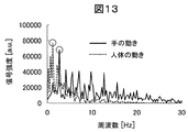
- FIG. 13 is a diagram illustrating frequency components of signals obtained by hand movements and human body movements.
- a solid line indicates a signal obtained by hand movement
- a broken line indicates a signal obtained by the movement of the human body.
- the peak of hand movement is 2.7 Hz
- the peak of human movement is 1.2 Hz.
- the movement of the human body is measured at a speed that is enough to walk in the office. These speed differences (frequency differences) are about 2.3 times, and by extracting this speed difference, the movement of the hand and the human body can be separated with higher accuracy.
- FIG. 14 is a diagram showing an example of detecting the movement of a human body, and shows an example of walking at a speed v in the x direction so as to cross the detection range 2a.
- the movement in the x direction is detected using the detection elements CH4 and CH2 of the sensor 2 of FIG.
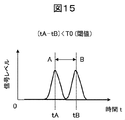
- FIG. 15 is a diagram showing a time change of the output signal of the sensor 2 by the human body.
- tA indicates the time when the human body crosses the position A within the detection range 2a
- tb indicates the time when the human body crosses the position B within the detection range 2a.
- this speed difference is used to determine whether or not the moving body indicates a gesture from the speed of the moving body that has moved within the detection range 2a.
- a threshold T0 for the travel time from A to B is set.
- the time tA at which the detection signal output from the sensor 2 (CH4) shows a peak when the moving body crosses the position A of the detection range.
- the time difference (tB ⁇ tA) from the time tB when the detection signal output from the sensor 2 (CH2) shows a peak when crossing the position B of the detection range is compared with the threshold value T0. If (tB ⁇ tA) ⁇ T0 as a result of the comparison, the moving body is determined or detected as a hand gesture. If (tB-tA)> T0, it is determined that the moving body is not a gesture (or is not detected as a gesture). In the experiments of the present inventors, the speed at which a person moves is 1 to 1.5 m / sec, and the speed of hand shaking is 2 to 4 m / sec. Therefore, the threshold value T0 may be set based on these. . As described above, in this embodiment, the passing time of the moving body is measured and compared with the threshold value T0, thereby eliminating the false detection due to the movement of the human body other than the hand of the operator and further improving the detection accuracy of the gesture. Can do.
- Example 3 describes a detection element 16 used for gesture detection.
- the detection element 16 of the sensor 2 an element that detects infrared radiation from a hand (human body) such as a thermopile can be used.
- a thermopile an element that detects infrared radiation from a hand (human body)
- thermopile an element that detects infrared radiation from a hand (human body)
- thermopile when using a thermopile, signal detection may not be possible due to the influence of the ambient temperature. In order to eliminate the influence, it is desirable to have a circuit configuration that detects the time change of the signal (hereinafter referred to as a change detection circuit).
- a change detection circuit a circuit configuration that detects the time change of the signal
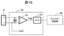
- FIG. 16 is a diagram showing an example of a detection circuit configuration of the sensor 2 using a thermopile.
- An output signal from the sensor 2 (detection element 16) is detected by the signal detection unit 3a and sent to the gesture determination unit 3b.
- the signal detector 3a includes an amplifier 18 that amplifies a signal, an A / D converter 19 that performs A / D conversion, and electronic components such as a resistor capacitor.
- the A / D conversion unit 19 may use an IC having an A / D conversion function, or may use a microcomputer having an A / D function and perform processing together with the gesture determination unit 3b in the subsequent stage.
- thermopile used for the sensor 2 outputs a signal substantially proportional to the temperature difference between the temperature of the object (for example, a human hand) and the thermopile itself.
- the output signal of the thermopile is amplified by the amplifier 18. Further, the positive terminal of the thermopile is input to the positive terminal of the amplifier 18, and the reference voltage Vref is input to the negative terminal. Then, the amplifier 18 amplifies the detection signal from the thermopile input to the positive terminal with reference to the reference voltage Vref input to the negative terminal, and outputs the voltage Vobj.
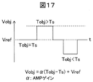
- FIG. 17 is a diagram showing the output voltage of the amplifier 18 with respect to the object temperature.
- the object temperature is Tobj
- the thermopile temperature is Ts
- the reference voltage is Vref
- the output voltage of the amplifier 18 is Vobj
- Toobj> Ts Vobj> Vref
- Vobj ⁇ Ts Vobj ⁇ Vs.
- the output voltage Vobj of the amplifier 18 is determined by the relationship between the temperature Tobj of the object and the temperature Ts of the thermopile, and is expressed by Expression (4).
- Vobj ⁇ (Tobj ⁇ Ts) + Vref (4)
- ⁇ is a coefficient determined by the sensitivity of the thermopile and the gain of the amplifier 18.
- Equation (4) when the difference between the thermopile temperature Ts and the object temperature Tobj is increased, the output voltage Vobj is saturated and sticks to Vcc or GND. In the image projection apparatus 1, due to the heat generated from the light source unit 4b, the thermopile temperature Ts also rises significantly, making it difficult to detect the object. In order to avoid this, a change detection circuit is used to eliminate the influence of the temperature increase of the thermopile.
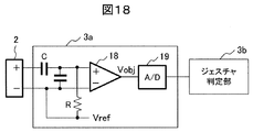
- FIG. 18 is a diagram illustrating a configuration of a change detection circuit of the sensor 2.
- the change detection circuit has a configuration in which a capacitor C is inserted in series between the positive terminal of the sensor 2 and the positive terminal of the amplifier 18, and a resistor R is inserted between the positive terminal and the negative terminal of the amplifier 18.
- the CR time constant circuit reacts to a temperature change in a short time, but does not depend on the temperature Ts increase of the thermopile, which is a long-time temperature change.
- This time constant is desirably 3 sec or less, for example, in accordance with the operation time of the gesture.
- the output voltage Vobj at this time is expressed by Expression (5) when the object temperature changes from Tobj1 to Tobj2.
- Vobj ⁇ (Tobj2 ⁇ Tobj1) (5)
- the gesture direction is mainly described in the x direction and the y direction.
- the detection of the gesture in the z direction will be described.
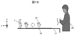
- FIG. 19 is a diagram showing a gesture in the z direction, and the operation in the z direction is performed by covering the image projection apparatus 1 with the hand 21.
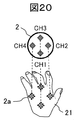
- FIG. 20 is a diagram showing the relationship between the hand and the detection range during the z-direction gesture.
- the detection range 2a of each detection element CH1 to CH4 of the sensor 2 is assumed to be included in the range of the hand 21.
- the detection of the gesture in the z direction is determined using the detection signals of the detection elements CH1 to CH4 based on whether or not these detection signals are synchronized.
- FIG. 21 is a diagram showing a time change of the sensor signal of each CH during the z-direction operation.
- the change detection circuit (FIG. 18) of the third embodiment is used for this detection circuit, and the sensor signal on the vertical axis is the output level of the amplifier 18.
- the sensor signal from each CH rises, and the sensor signal peaks when the detection range is completely covered. If the state covering the detection range continues, the sensor signal decreases after a predetermined holding time according to the time constant of the capacitor C and the resistance R of the change detection circuit.
- the gesture is an original z direction, the rise time and holding time of the signal detected by each CH should be synchronized. Therefore, it is determined whether or not the gesture is in the z direction by evaluating the difference between the rise times (tmin to tmax) of each CH and the holding time “thold” in which the signal level is equal to or higher than the threshold value Vth.
- FIG. 22 is a diagram showing a flowchart for detecting a z-direction gesture.
- the determination in the z direction has three stages: threshold determination, rise time difference determination, and signal level maintenance period determination. This will be described below with reference to a flowchart.
- threshold determination is performed.
- a signal of each CH obtained by A / D converting the output signal of the sensor 2 by the signal detection unit 3a is used.
- a signal change from the offset level is detected, and when the signal level exceeds the threshold value Vth, the next rise time is detected. If the signal level does not exceed the threshold, the threshold determination is repeated.
- the rise time is detected.
- the time exceeding the threshold value Vth is detected for each CH.
- the signal of each CH rises almost simultaneously with respect to the gesture in the z direction.
- a difference occurs in the rise time of each CH. Therefore, the rise time is detected to distinguish the gesture in the z direction from the movement in the other direction.
- the rise time difference is determined. Of the rise time obtained in S103, the minimum value tmin and the maximum value tmax are obtained. If the rise time difference (tmax ⁇ tmin) is less than the predetermined time, the next signal level maintaining period determination (S105) is performed. If the rise time difference (tmax ⁇ tmin) is equal to or greater than the predetermined time, the process returns to the threshold determination process (S101).
- the value of the predetermined time depends on the movement speed of the hand, but is preferably about 50 to 100 msec in consideration of operability.
- the signal level maintenance period is determined.
- a period thold in which the signal levels of all the detection elements CH1 to CH4 exceed the threshold value Vth is detected. If the detected threshold is equal to or longer than a predetermined time, it is regarded as a gesture in the z direction.
- the predetermined time is desirably about 600 msec as a time that does not cause discomfort to humans. If the time is longer than that, the time for covering the sensor 2 with the hand becomes longer, so that the operator feels stress.
- a control signal corresponding to the operation is output.
- the present embodiment it is possible to suppress erroneous detection that is not intended by the operator in gesture detection in the z direction. For example, in the operation of pointing a finger on the image, the possibility of completely covering the detection range 2a is reduced unless the position is very close to the sensor 2, so that the z-direction operation and the finger pointing operation can be separated. Moreover, you may recognize as a gesture of az direction by repeating the operation
- Example 5 a method for detecting a failure state of the detection element 16 in the sensor 2 will be described.
- the change state detection circuit (FIG. 18) of the third embodiment is used, and the failure state is determined by comparing the signal levels of the plurality of detection elements 16.
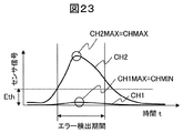
- FIG. 23 is a diagram showing temporal changes in the output signals of a normal detection element and a detection element in a failure state.
- CH1 is shown as a failure detection element (failure element)
- CH2 is shown as a normal detection element (normal element).
- the normal element CH2 outputs a signal (maximum value CH2MAX), but the faulty element CH1 has a small or zero signal output (maximum value CH1MAX). Therefore, failure determination is possible by comparing the signal level of each CH.
- FIG. 24 is a diagram showing a flowchart for determining a failure of the detection element.
- failure determination using four detection elements will be described.
- the failure determination is performed in front of the sensor 2 and includes five levels of determination: threshold determination for each detection element, count clear determination, error exclusion determination, error determination, and failure determination.
- threshold determination for each detection element
- count clear determination for each detection element
- error exclusion determination for each detection element
- failure determination for failure determination
- failure determination includes five levels of determination: threshold determination for each detection element, count clear determination, error exclusion determination, error determination, and failure determination.
- it demonstrates along a flowchart.
- the maximum value of each CH is detected.
- the maximum value of each detection element hereinafter, CH1MAX, CH2MAX, CH3MAX, CH4MAX
- a count clear determination is performed.
- the maximum value of each CH detected in S203 is compared with the threshold Eth. If it is greater than or equal to the threshold, the error count for that CH is cleared. If it is less than the threshold, the error count is not cleared and the process proceeds to maximum value detection (S206).
- the threshold Eth may be set to be equal to or higher than the noise level, or may be set according to the magnitude of the signal level. Any level can be used as long as it is detected that a hand gesture has been input.
- the error detection period may be determined according to the urgency of detection together with the error count value at the time of failure determination. If error detection is required immediately in time, the detection period and the error count number may be set small.
- maximum value detection is performed.
- CHMAX maximum value
- CHMIN minimum value among the maximum values (CH1MAX, CH2MAX, CH3MAX, CH4MAX) of each CH are obtained.
- error exclusion determination is performed.
- the error exclusion determination is introduced to distinguish whether the detection element is in a failure state or whether the detection element is normal but no signal is detected.
- the error exclusion determination pattern will be described with reference to FIGS.
- FIG. 25A and 25B are diagrams showing hand movement patterns, where FIG. 25A shows a combination of hand movements in the y direction, and FIG. 25B shows a combination of hand movements in the x direction.
- FIG. 25A shows a combination of hand movements in the y direction
- FIG. 25B shows a combination of hand movements in the x direction.
- FIG. 26 is a diagram showing patterns to be excluded from error determination.
- the cases of (1), (3), (4), and (6) in FIG. 25 are excluded, and the combinations of the minimum value CHMIN and the maximum value CHMAX at that time are shown. That is, the combination of CHMAX and CHMIN shown in FIG. 26 is excluded from the error determination.
- error determination is performed.
- the maximum value (CH1MAX, CH2MAX, CH3MAX, CH4MAX) of each detection element is compared with the CHMAX value, and an error is determined when Expression (6) is satisfied. (Maximum value of each detecting element) ⁇ CHMAX / (constant coefficient) (6)
- the error count value is incremented.
- failure determination is performed.
- the count value of the error determination process in S208 exceeds a certain value, it is determined that the detection element is in a failure state.
- the count value may be set arbitrarily together with the detection period when detecting the maximum value of each detection element.
- the failure state of the detection element 16 in the sensor 2 can be detected with high accuracy.
- Example 6 describes an example of assigning video screen operation functions to gesture types.
- the main functions of the video screen operation are PageUp / PageDown (function to move the page to the next or previous page when displaying PowerPoint, pdf, etc.), PowerOn / Off (power ON / OFF), FrameLock (stop the display screen), There are ENTER (selection / determination), Blank (display ON / OFF), and Zoom (enlarge display). Gesture ON / OFF (gesture valid / invalid switching) is added to these functions, and each screen operation function by the gesture is realized.
- PageUp / PageDown function to move the page to the next or previous page when displaying PowerPoint, pdf, etc.
- PowerOn / Off power ON / OFF
- FrameLock stop the display screen
- ENTER selection / determination
- Blank display ON / OFF
- Zoom enlarge display
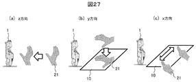
- FIG. 27 is a diagram showing gesture types, in which (a) shows a gesture in the z direction, (b) shows a gesture in the y direction, and (c) shows a gesture in the x direction.
- the gesture in the z direction in (a) is a pushing operation, which is a large operation compared to the operation in the other direction. Therefore, it is desirable as an intuitive operation to assign a function that greatly changes the display state of the projector. It is desirable to assign a function for changing the display state, such as Power ON / OFF, Blank, and Frame Lock, to the gesture in the z direction.
- the y-direction gesture works like pressing a switch on the screen. Therefore, it is desirable to assign it to input or function switching. It is desirable to assign functions such as Zoom, ENTER, and Geometry ON / OFF to the y-direction gesture.
Landscapes
- Engineering & Computer Science (AREA)
- General Engineering & Computer Science (AREA)
- Theoretical Computer Science (AREA)
- Human Computer Interaction (AREA)
- Physics & Mathematics (AREA)
- General Physics & Mathematics (AREA)
- User Interface Of Digital Computer (AREA)
Abstract
映像投写装置1は、操作者のジェスチャをセンサ2にて検出し操作信号を生成する操作検出部3と、映像信号に基づき映像光を生成し投写面に映像を投写する映像投写部4と、を備える。投写面が映像投写装置1が設置される設置面11である場合、操作検出部3のセンサ2は、操作者のジェスチャを検出する複数の検出素子16から構成される。複数の検出素子の検出範囲は互いに異なり、複数の検出素子の少なくとも1個は、その検出範囲に投写される映像画面が所定の割合以上含まれるジェスチャ監視素子16gである。
Description
本発明は、ジェスチャ検出機能を有する映像投写装置に関する。
本技術分野の背景技術として、特許文献1がある。該文献の要約には、課題として、「映像光の投影方向とは異なる所定方向において行われた操作者のジェスチャを検出可能とし、プロジェクタと投影面との間隔が狭い場合でも操作者のジェスチャを検出することができ、投影面に投影された画像の視認性を低下させることなく、さらに、操作者のジェスチャの検出感度を向上させることができる画像投影装置を提供する」と記載され、解決手段として、「光源からの光を光変調素子により映像光に変調し、結像光学系を介して映像光を投影し、投影面20に画像表示を行う画像投影装置1であって、映像光の投影方向D1とは異なる所定方向において行われた操作者OPのジェスチャJSを検出することが可能なジェスチャ検出手段13と、ジェスチャ検出手段13によるジェスチャの検出可能範囲を定めるための検出範囲設定手段と、ジェスチャ検出手段13の検出結果であるジェスチャ情報に基づいて制御信号を生成する制御信号生成手段とを備えた構成としてある」と記載されている。
特許文献1では、ジェスチャ検出手段は検出範囲に物体が入った際に操作者のジェスチャと認識するものであり、その物体が手であるか人体であるかを区別することは考慮されていない。そのため、検出範囲を例えば人が通ることでジェスチャと認識され、操作者の意図に反した制御が行われてしまうという問題が生じる。
映像投写装置の中で、特に短焦点レンズを用いた机上投写プロジェクタにおいては、操作者は、映像が投写されている机上面に近い位置で操作する。この場合、ジェスチャの検出範囲に操作者が手を入れようとすると、背面にある操作者の人体も含まれてしまうことが多い。その結果、手と人体のどちらが検出されたかを識別できず、誤動作の原因となる。
本発明の目的は、操作者の手と人体を区別することでジェスチャの検出精度を向上させ、操作者の意図に従った制御を行う映像投写装置を提供することである。
本発明は、操作者のジェスチャに基づいて投写する映像を制御可能な映像投写装置であって、映像信号に基づき映像光を生成し投写面に映像を投写する映像投写部と、操作者のジェスチャを検出するためのセンサと、該センサにて検出されたジェスチャに基づき前記投写映像を制御するための操作信号を生成する操作検出部と、を備え、前記センサは複数の検出素子を含み、前記投写面が当該映像投写装置が設置される設置面である場合、該複数の検出素子の少なくとも1個の所定検出素子は、その検出範囲に含まれる前記投写される映像画面が所定の割合以上となることを特徴とする。
本発明によれば、ジェスチャの誤検出がなく操作者の意図に従った制御を行う映像投写装置を提供できる。
以下、本発明の映像投写装置の実施例について図面を用い説明する。以下に述べる実施例では、机上投写プロジェクタを対象とし、操作者のジェスチャに基づいて投写する映像を制御する構成について説明する。
図1は、実施例1に係る映像投写装置の概観図である。映像投写装置1は、設置面(机)11上に設置され、装置内部で生成した映像光を投写レンズ4dで拡大した後、反射ミラー4eで反射して設置面11に映像画面10を投写する。投射映像のフォーカスは、フォーカスリング15で調整する。反射ミラー4eは折り畳み可能に構成されており、不使用時には反射面が映像投写装置1と対向するように収納される。映像投写装置1は、操作者のジェスチャを検出するセンサ2を有する。センサ2は、検出範囲2a内の操作者の手の動きとその方向を検出する。センサ2は、操作者の手を検出するために光源を有してもよいし、光源を有さないパッシブ型のセンサであってもよい。例えばパッシブ型のセンサセンサ2として、操作者の手の温度を検出する温度センサである焦電型センサを使用することもできる。
図2は、映像投写装置1の内部構成を示すブロック図である。映像投写装置1は、操作検出部3と映像投写部4を有する。
まず操作検出部3から説明する。操作検出部3は、信号検出部3a、ジェスチャ判定部3b、操作信号生成部3cを有する。信号検出部3aはセンサ2からの信号を検出して、ジェスチャ判定部3bに供給する。ジェスチャ判定部3bは供給された信号に基づき、様々なジェスチャの動きを判別する処理を行う。操作信号生成部3cはジェスチャ判定部3bの判定結果に応じた操作信号を生成し、PC(Personal Computer)、スマートフォンなどの外部機器6に出力する。外部機器6は、操作信号生成部3cからの操作信号に応じて、映像投写装置1に供給する映像信号を制御する。
このように、操作者のジェスチャに基づいて操作信号が生成され、この操作信号により映像投写装置1から投写される映像が制御される。例えば、操作者が手を動かした方向に応じて、表示する画像をスクロール、コマ送り、或いはスライドを切替するような動作を行う。なお、外部機器6は、映像投写装置1に映像信号を供給する装置であれば何でもよい。例えば、映像投写装置1に備えられたカードインタフェースに挿入されるカード状の記憶媒体であってもよい。
次に映像投写部4について説明する。映像投写部4は、映像制御部4a、光源部4b、光制御部4c、投写レンズ4d、投写ミラー4eを有する。映像制御部4aは、外部機器6から供給された映像信号に応じ、光源部4b、光制御部4cに制御信号を送る。光源部4bは、ハロゲンランプ、LED、レーザ等の光源であり、映像制御部4aの制御信号に応じ光量を調整する。光源部4bがR、G、Bの3色を含む場合、映像信号に応じ各々独立して光量を制御してもよい。光制御部4cは、ミラー、レンズ、プリズム、イメージャ(例えば液晶パネルのような表示デバイス)等の光学系構成要素を有し、光源部4bから出射された光を用いて、外部機器6から供給された映像信号に基づく光学的な映像を生成する。投写レンズ4dは光制御部4cから出力された映像を拡大する。投写ミラー4eは投写レンズ4dから放射された光を反射し、設置面11に映像画面10を投写する。投写ミラー4eは非球面ミラーを用いており、同サイズの映像画面を投写する場合、一般的な投写装置と比較し投写距離を短くすることができる。本実施例では投写ミラー4eを用いた映像投写部4の例を示したが、映像投写を実現できる構成であれば他の構成でもよい。なお、以下では投写レンズ4dと投写ミラー4eを併せて、投写光学部と呼ぶ。
次に、センサ2の配置に関し説明するが、図3~図6を用いて、一般的な配置における問題点を述べる。以後、説明を容易にするためにx、y、z軸を用いて方向を示す。設置面(机上面)11はxz面で、映像投写装置1はy方向に起立して設置される。映像投写装置1に対し操作者はz方向に位置することになる。操作者の操作方向は、x、y、zの3方向が存在する。
図3は、センサ2を映像投写装置1の上側(y方向)に配置した場合を示す図である。このときのセンサ2の検出範囲を2aで示す。人間による直感的な操作を行う場合、映像画面10が投写された設置面11上に近い空間でジェスチャ操作することが想定される。図3は、このときの操作者の人体20と手21の位置関係を示す。このようにセンサ2を配置した場合、映像投写装置1に近い位置では手21が検出範囲2aから外れることとなり、ジェスチャ検出が不可能となる(×印)。
図4は、センサ2を映像投写装置1の上側に配置し、かつ検出範囲2aを拡大した場合を示す図である。検出範囲2aを映像画面10を含むように拡大した場合、映像投写装置1に近い位置では良好に検出可能だが、映像投写装置1から遠い映像画面10端部位置では検出感度が低下するため、ジェスチャ判定が困難になる。よって、映像画面の端部位置まで感度を低下させず、かつ設置面に近い高さで検出可能とすることが必要である。
図5は、センサ2を映像投写装置1の下側に配置した場合を示す図である。このようなセンサ配置と検出範囲2aの場合、センサ2からの距離によらず感度が低下しないため、設置面に近い映像画面上でジェスチャ検出が可能である。センサ2の設置面11からの高さは、操作者の手21の高さに合わせて設定することが望ましい。一例として経済産業省の人体寸法・形状データの調査によると、手の長さは平均19cmであることから、それ以下の値に設定すればよい。
しかしながら図5のように検出範囲2aを設定すると、手21の動きだけではなく背景の人体20の動きも検出することとなり、操作者の意図と異なるジェスチャを検出することになる(以下、誤検出と呼ぶ)。
図6は、人体の動きによる誤検出の例を示した図である。人体20がx方向に移動してセンサ2の検出範囲2a内に入ると、センサ2は人体20の動きと方向をジェスチャと認識し、誤検出が生じる。そのため、手21によるジェスチャと人体20の動きを分離することが必要となる。
このような問題点を鑑み、以下では、映像画面端での感度を低下させず、設置面に近い映像画面上での直感的な操作が可能で、誤検出を抑制する構成を述べる。すなわち、誤検出を抑制するためのセンサ2の構成と、手と人体の動きを分離する検出範囲2aの設定を説明する。
図7は、センサ2の構成例と検出範囲を示した図であり、(a)はz方向から見た図、(b)はy方向とx方向から見た図である。
(a)で示すように、センサ2は複数(ここでは4個)の検出素子16を有し、それぞれの検出素子16は異なる検出範囲を持つ。以下、センサ2の中心からy’方向、x’方向、y方向、x方向に位置する検出素子をそれぞれCH1、CH2、CH3、CH4と呼ぶことにする。センサ2では、各検出素子16からの信号振幅と信号出力のタイミングを用いてジェスチャを検出する。例えばxからx’方向に手振りをすると、CH4の信号出力後にCH1とCH3の信号が検出され、最後にCH2の信号が検出される。このときCH4とCH2の信号出力には時間差が生じる。時間的にCH4、CH2の順で信号が出力されれば、その時の手振りはxからx’方向に向かう手振りであると判定することができる。以下の説明では4個の検出素子16を用いているが、検出素子数は4個に限らず、手振りの動き方向に応じて適宜増減すればよい。
(b)は、センサ2のxz断面とyz断面方向の各検出素子16の検出範囲2aの例を示す。ここでは、各検出素子16(CH1~CH4)の検出範囲2aが、センサ2の中心軸(z方向)から放射状(x方向、y方向)に拡がるように配置した例を示す。なお、各CHの検出範囲2aの中心軸は、必ずしも放射状に拡がる必要はなく、センサ2の中心軸に平行であっても、各CHの検出範囲2aが異なればよい。また、各CHの検出範囲2aの一部が重なっていてもよい。
次に、手と人体の動きを分離するための検出範囲2aの設定について説明する。
図8は、検出範囲2aの設定例を示した図である。検出素子16のうち少なくとも1個の所定検出素子は、その検出範囲2aに含まれる映像画面10が所定の割合以上となるように設定する。以下、検出範囲2aに映像画面10が占める割合を「映像画面占有率」と呼ぶことにする。図8の場合は、所定検出素子をCH1の検出素子としており、この検出素子(CH1)は、他の素子よりも映像画面占有率が大きくなるよう設定している。映像画面占有率が所定値以上の検出素子を用いることで、操作者の映像画面上での手の動きと、操作者の人体の動きを分離することができる。以降、映像画面占有率が所定値以上としている所定検出素子を「ジェスチャ監視素子」(符号16g)と呼ぶことにする。図7と図8において、CH1がジェスチャ監視素子16gである。
図8は、検出範囲2aの設定例を示した図である。検出素子16のうち少なくとも1個の所定検出素子は、その検出範囲2aに含まれる映像画面10が所定の割合以上となるように設定する。以下、検出範囲2aに映像画面10が占める割合を「映像画面占有率」と呼ぶことにする。図8の場合は、所定検出素子をCH1の検出素子としており、この検出素子(CH1)は、他の素子よりも映像画面占有率が大きくなるよう設定している。映像画面占有率が所定値以上の検出素子を用いることで、操作者の映像画面上での手の動きと、操作者の人体の動きを分離することができる。以降、映像画面占有率が所定値以上としている所定検出素子を「ジェスチャ監視素子」(符号16g)と呼ぶことにする。図7と図8において、CH1がジェスチャ監視素子16gである。
図9は、ジェスチャ監視素子による手と人体の動きの分離を説明する図である。図8に示す手21の動きと人体20の動きに対し、ジェスチャ監視素子CH1(16g)とその他の検出素子CH3に生じるセンサ信号の変化を示している。
ジェスチャ監視素子CH1において、手21の動きは検出範囲2a(CH1)を横切るため大きな信号変化が生じる。しかし、人体20の動きは検出範囲2a(CH1)を横切る割合が少ないため信号変化は小さい。一方他の検出素子CH3では、手21と人体20のいずれの動きも検出するので信号変化は大きくなる。このようにジェスチャ監視素子は、操作者の手の動きを他の人体の動きよりも優先して検出する。ジェスチャ監視素子の信号レベルと他の検出素子の信号レベルを比較することで、手と人体の動きを分離することができる。手と人体の動きを分離するには、ジェスチャ監視素子と他の検出素子の信号レベルに明確な差が発生すれば良く、これを満足するようジェスチャ監視素子の映像画面占有率を定めればよい。例えば、映像画面占有率が約50%以上とすれば、実用的に満足できるものとなる。
前述の例では、ジェスチャ監視素子16gはセンサ2内に含まれる構成としたが、ジェスチャ監視素子はセンサ2と別に設けてもよい。ジェスチャ監視素子がセンサ2内に含まれ、センサ2を下側(設置面側)に傾けた場合を想定する。このときジェスチャ監視素子は映像画面(設置面)に検出範囲を持つようになる。しかし、他の検出素子も下向きとなるため、映像画面の端部における検出感度が低下する可能性がある。これに対しジェスチャ監視素子を別体として設けることで、センサ2の操作性に対する自由度が高まり、映像画面端部での感度を確保できるメリットがある。
図10は、ジェスチャ監視素子をセンサ2と別体に構成した例を示す図である。映像投写装置1には、センサ2とは別体のジェスチャ監視素子17gを設け、ジェスチャ監視素子17gは映像画面10のみを検出するよう異なる位置に配置する。領域2bはジェスチャ監視素子17gが検出する範囲を示し、この領域2bにおける手の動作のみ検出可能となる。このようにジェスチャ監視素子を別体として設けることで、検出感度を低下させず、手と人体の分離を行うことが可能となる。
図11は、ジェスチャ監視素子による操作範囲を制限した例を示す図である。別体で構成したジェスチャ監視素子17gは、手と人体の分離を行うだけでなく、その検出範囲2bを制限することで操作者の操作範囲を制限することが可能である。例えば、操作者の操作範囲を映像画面10の中央のみに制限するような使い方が可能である。
また、ジェスチャ監視素子17gの検出範囲2bを可変とすることで、状況に応じて操作範囲の制限を変更することができる。例えば、映像画面上どの位置でも操作可能とする場合は検出範囲2bを映像画面10全体に拡げ、映像投写装置1の正面のみでの操作に制限したい場合は検出範囲2bを映像画面中央に制限する。その面積を所定の割合(例えば1/3)とすれば、操作可能範囲を1/3に制限できる。また、使用環境により操作範囲を、映像画面の左側、右側、四隅等、変更可能なことは言うまでもない。操作範囲は映像投写装置1のメニュー画面から切替えてもよいし、機械的なスイッチで切替えてもよい。もしくは、操作範囲切替モードを有効にした後ジェスチャにより操作範囲を切替えてもよい。操作範囲切替モードはメニューにより有効にしてもよいし、特定のジェスチャにより有効化してもよい。
また、センサ2による検出範囲の設定は、誤検出抑制と操作性のどちらを優先するかによって最適化できる。
図12は、用途に応じたセンサ2の検出範囲の設定を示す図であり、設置面11に映像を投写するような映像投写装置1の設置において、(a)は誤検出抑制を優先する場合、(b)は操作性を優先する場合を示す。ここでは、いずれの場合もセンサ2の中心軸は、映像投写装置の設置面に対し傾くように映像投写装置に取り付けられている。ここで、設置面11からセンサ2の中心までの高さh、センサ2の検出範囲2aの角度を2θ、設置面に対するセンサ2の中心軸の傾きφ、センサ2から映像画面10の端部までの距離L、手21の全長をHとする。
図12は、用途に応じたセンサ2の検出範囲の設定を示す図であり、設置面11に映像を投写するような映像投写装置1の設置において、(a)は誤検出抑制を優先する場合、(b)は操作性を優先する場合を示す。ここでは、いずれの場合もセンサ2の中心軸は、映像投写装置の設置面に対し傾くように映像投写装置に取り付けられている。ここで、設置面11からセンサ2の中心までの高さh、センサ2の検出範囲2aの角度を2θ、設置面に対するセンサ2の中心軸の傾きφ、センサ2から映像画面10の端部までの距離L、手21の全長をHとする。
まず(a)の誤検出抑制を優先する場合を説明する。操作に必要な範囲は映像画面10内であるため、画面端に検出範囲2aを設定するための関係式は(1)式のようになる。
(φ-θ)=tan-1(h/L)・・・(1)
(1)式のように設定することで、センサ2は映像画面10の外側に存在する人体等の動きを検出しないので、誤検出を抑制することができる。
(φ-θ)=tan-1(h/L)・・・(1)
(1)式のように設定することで、センサ2は映像画面10の外側に存在する人体等の動きを検出しないので、誤検出を抑制することができる。
次に(b)の操作性を優先する場合を説明する。ジェスチャを直感的に行うためには映像画面10に近い高さで操作を行う。そのため、手21のサイズHを基準に検出範囲2aを決定することにより、ジェスチャ監視素子16gの検出範囲を決定する。ここでは映像画面端部を操作する手21の高さ中央H/2にセンサ2の中心軸を設定する。このときの関係式は(2)、(3)式のようになる。
φ=tan-1((H/2-h)/L)・・・(2)
ただし、θ-φ>tan-1(h/L)・・・(3)
一例として手の長さH=19cmのときは、センサ2の中心軸が映像画面端において、設置からの高さ9.5cmを通るように設定すればよい。
φ=tan-1((H/2-h)/L)・・・(2)
ただし、θ-φ>tan-1(h/L)・・・(3)
一例として手の長さH=19cmのときは、センサ2の中心軸が映像画面端において、設置からの高さ9.5cmを通るように設定すればよい。
次に、図1を参照して、映像投写装置1に対するセンサ2の取付け位置について説明する。センサ2の取付け位置は、スペース確保が容易で、映像投写部4から投写される映像光(投写光)の影響を受けにくくするため、設置面11に映像を投写するように映像投写装置1を配置した場合において、映像光を出力する映像光出力部である投写レンズ4dの下方(好ましくは直下)とするのがよい。センサ2の検出範囲を設置面11の映像画面10上に設定するためには、センサ2を映像画面の近くに配置することが望ましい。ここで映像投写部4は、設置面からの距離を設けるため中央より上側に配置され、投写レンズ4dからの出射方向は上側となる。そのため投写レンズ4d下側にスペースを確保しやすい。また、映像投写部4によるセンサ2への直接光による影響は少なくなる。
以上まとめると、センサ2の好ましい設置位置の例は、設置面11からの高さh=10cm以内、水平方向に対するセンサ2の中心軸の傾きφ=±5°、検出範囲2aの検出幅角2θ=15~35°である。
また、センサ2の左右方向(x方向)の検出範囲に関しても合わせて調整を行うのがよい。人間の水平方向(x方向)の手振りは20~30cmが適切であり、それ以上になると手振りが大きくなるため操作性が損なわれる。一方非常に狭い範囲に設定すると、ちょっとした仕草により反応するため誤検出が発生する可能性がある。そのため水平方向の距離20~30cmを基準に調整するのが望ましい。例えば映像画面端で手振りが20~30cmとなるよう検出範囲を調整してもよい。また、各検出素子の検出範囲を独立して設定してもよい。等方的に拡がる視野ではなく、異方性をもつ視野に設定してもよい。例えば水平方向(x方向)は映像画面端で20~30cmに拡がるように設定し、垂直方向(y方向)は手振りが小さい方が操作者にとって好ましいため、10cm程度の拡がりに設定してもよい。このように、操作性に応じ必要な検出範囲を適宜設定するのがよい。
実施例2では、ジェスチャ監視素子を用いるとともに、手と人体の動作速度の違いを利用して手と人体の動きを分離し、高精度にジェスチャを検出するものである。ここでは、まず手と人体の動作速度の違いを説明し、手と人体の動きを分離する速度制約に関し説明する。
図13は、手の動きと人体の動きによって得られる信号の周波数成分を示した図である。実線が手の動き、破線が人体の動きによって得られる信号を示す。手の動きのピークは2.7Hzであり、人体の動きのピークは1.2Hzである。なお、人体の動きはオフィス内を歩く程度の速度で測定したものである。これらの速度差(周波数差)は約2.3倍であり、この速度差を抽出することで手と人体の動きをより高精度に分離することができる。
次に、手と人体の動きを分離する速度制約に関し説明する。
図14は、人体の動きを検出する一例を示した図であり、検出範囲2aを横切るようにx方向に速度vで歩いている例を示す。人体20は、点Aを時間t=tAで、点Bを時間t=tBで通過したとする。ここでは、図7のセンサ2の検出素子CH4とCH2を用いて、x方向の動きを検出する。
図14は、人体の動きを検出する一例を示した図であり、検出範囲2aを横切るようにx方向に速度vで歩いている例を示す。人体20は、点Aを時間t=tAで、点Bを時間t=tBで通過したとする。ここでは、図7のセンサ2の検出素子CH4とCH2を用いて、x方向の動きを検出する。
図15は、人体によるセンサ2の出力信号の時間変化を示した図である。tAは検出範囲2a内の位置Aを人体が横切る時間を示し、tbは検出範囲2a内の位置Bを人体が横切る時間を示す。人体20が位置AからBまでを横切る速度vは、v=(AからBまでの距離)/(tB-tA)から求まる。
一般に、人が動く速度と手振り(ジェスチャ)の速度に差があり、図13に示したように、手振りの速度の方が人の動く速度よりも速い。本実施例はこの速度差を利用し、検出範囲2a内で動いた移動体の速度から、当該移動体がジェスチャを示すものか否かを判定する。具体的には、AからBまでの距離は検出範囲2aに応じて決まるため、AからBまでの移動時間に対する閾値T0を設定しておく。そして、図14に示されるように、移動体がAからBに移動する場合に、移動体が検出範囲のA位置を横切る時にセンサ2(CH4)から出力された検出信号がピークを示す時間tAと、検出範囲のB位置を横切る時にセンサ2(CH2)から出力された検出信号がピークを示す時間tBとの時間差(tB-tA)を閾値T0と比較する。比較の結果、(tB-tA)<T0であれば、当該移動体を手によるジェスチャとして判定或いは検出する。(tB-tA)>T0であれば、当該移動体はジェスチャではないと判定する(或いはジェスチャとして検出しないようにする)。本発明者らの実験では、人が動く速度は1~1.5m/secであり、手振りの速度は2~4m/secであるため、これらを基にして上記閾値T0を設定してもよい。このように本実施例では、移動体の通過時間を測定して閾値T0と比較することで、操作者の手以外の人体の動きによる誤検出を排除し、ジェスチャの検出精度をさらに向上することができる。
実施例3では、ジェスチャ検出に用いる検出素子16について述べる。センサ2の検出素子16には、サーモパイルのような手(人体)からの赤外線放射を検出する素子を使用できる。またLEDとPDを用いたアクティブセンサを用いてもよい。手の動きを検出可能なセンサであればこの限りではない。
例えばサーモパイルを用いる場合、周辺温度の影響により信号検出ができなくなる場合があり、その影響をなくすため信号の時間変化分を検出する回路構成(以下、変化分検出回路)とするのが望ましい。以下サーモパイルを用いた検出回路の構成、その問題点、変化分検出回路の構成に関し説明する。
図16は、サーモパイルを用いたセンサ2の検出回路構成の一例を示した図である。センサ2(検出素子16)からの出力信号は、信号検出部3aで検出され、ジェスチャ判定部3bに送られる。信号検出部3aは、信号を増幅する増幅器18、A/D変換を行うA/D変換部19、抵抗コンデンサ等の電子部品から構成される。A/D変換部19はA/D変換の機能をもつICを用いてもよいし、A/Dの機能をもつマイコンを使用し後段のジェスチャ判定部3bと合わせて処理してもよい。
センサ2(検出素子)に用いるサーモパイルは、対象物(例えば人の手)の温度とサーモパイル自身の温度差にほぼ比例した信号を出力する。サーモパイルの出力信号は増幅器18により増幅される。また、増幅器18の正極性端子にはサーモパイルの正極性端子信号が入力され、負極性端子には基準電圧Vrefが入力される。そして増幅器18は、負極性端子に入力された基準電圧Vrefを基準にして、正極性端子に入力されたサーモパイルからの検出信号を増幅し、電圧Vobjを出力する。
図17は、対象物温度に対する増幅器18の出力電圧を示した図である。対象物温度をTobj、サーモパイル温度をTs、基準電圧をVref、増幅器18の出力電圧をVobjとすると、Tobj=Tsの場合、Vobj=Vrefとなる。またTobj>Tsの場合、Vobj>Vrefとなり、Tobj<Tsの場合Vobj<Vsとなる。増幅器18の出力電圧Vobjは、対象物の温度Tobjとサーモパイルの温度Tsとの関係で決まり、式(4)で表される。
Vobj=α(Tobj-Ts)+Vref・・・(4)
ここで、αはサーモパイルの感度、増幅器18のゲインによって定まる係数である。
Vobj=α(Tobj-Ts)+Vref・・・(4)
ここで、αはサーモパイルの感度、増幅器18のゲインによって定まる係数である。
式(4)で示すように、サーモパイル温度Tsと対象物温度Tobjの差が大きくなると、出力電圧Vobjが飽和し、VccもしくはGNDに張り付くという問題を生じる。映像投写装置1では光源部4bからの発熱のため、サーモパイル温度Tsも大幅に温度上昇して、対象物の検出が困難になる。これを回避するため、変化分検出回路を使用しサーモパイルの温度上昇による影響をなくす。
図18は、センサ2の変化分検出回路の構成を示した図である。変化分検出回路は、センサ2の正極性端子と増幅器18の正極端子間に直列にコンデンサCを、増幅器18の正極性端子と負極性端子間に抵抗Rを挿入した構成である。この検出回路によれば、CR時定数回路により短時間での温度変化には反応するが、長時間の温度変化であるサーモパイルの温度Ts上昇には無依存となる。この時定数はジェスチャの操作時間に合わせ、例えば3sec以下とするのが望ましい。このときの出力電圧Vobjは、対象物温度がTobj1からTobj2に変化した場合、式(5)で表される。
Vobj=α(Tobj2-Tobj1)・・・(5)
このように変化分検出回路を用いることで、映像投写装置1内の温度上昇によるサーモパイルの温度上昇に依存せず、信号検出が可能となる。
Vobj=α(Tobj2-Tobj1)・・・(5)
このように変化分検出回路を用いることで、映像投写装置1内の温度上昇によるサーモパイルの温度上昇に依存せず、信号検出が可能となる。
前記各実施例では、ジェスチャの方向がx方向とy方向を主に説明したが、本実施例ではz方向のジェスチャの検出に関し説明する。
図19は、z方向のジェスチャを示した図であり、z方向の操作は映像投写装置1を手21で覆う動作で行う。
図20は、z方向ジェスチャ時の手と検出範囲の関係を示した図である。センサ2の各検出素子CH1~CH4の検出範囲2aは、手21の範囲に含まれるものとする。z方向のジェスチャの検出は、各検出素子CH1~CH4の検出信号を用いて、これらの検出信号が同期しているか否かで判定する。
図21は、z方向動作時の各CHのセンサ信号の時間変化を示した図である。この検出回路には、前記実施例3の変化分検出回路(図18)を用いており、縦軸のセンサ信号は増幅器18の出力レベルである。手21がセンサ2に近づくにつれ各CHからのセンサ信号が上昇し、検出範囲を完全に覆った時センサ信号はピークとなる。検出範囲を覆う状態が継続すると、変化分検出回路のコンデンサCと抵抗Rの時定数に従って、所定の保持時間後にセンサ信号が減少する。本来のz方向のジェスチャであれば、各CHで検出する信号の立上り時間や保持時間は同期するはずである。よって、各CHの立上り時間の差(tmin~tmax)と信号レベルが閾値Vth以上となっている保持時間tholdを評価することで、z方向のジェスチャであるか否かを判定する。
図22は、z方向ジェスチャの検出を行うフローチャートを示した図である。z方向の判定は、閾値判定、立上り時間差判定、信号レベル維持期間判定の3段階ある。以下フローチャートに沿って説明する。
S101~S102では、閾値判定を行う。閾値判定では、センサ2の出力信号を信号検出部3aにてA/D変換した各CHの信号を使用する。オフセットレベルからの信号変化を検出し、信号レベルが閾値Vthを超えたら次の立上り時間を検出する。信号レベルが閾値を超えなければ閾値判定を繰り返す。
S103では、立上り時間を検出する。立上り時間検出では、各CHについて閾値Vthを超えた時間を検出する。z方向のジェスチャに対し、各CHの信号がほぼ同時に立上るという特徴がある。一方z方向以外の動きに対しては、各CHの立上り時間に差が生じる。そこで、z方向のジェスチャと他の方向の動きを区別するため立上り時間を検出する。
S104では、立上り時間差を判定する。S103で得られた立上り時間のうち、最小値tminと最大値tmaxを求める。立上り時間差(tmax-tmin)が所定時間未満であれば、次の信号レベル維持期間判定(S105)を行う。立上り時間差(tmax-tmin)が所定時間以上であれば、閾値判定処理(S101)に戻る。所定時間の値は手の動き速度に依存するが、操作性を考慮すると50~100msec程度が望ましい。
S105では、信号レベル維持期間を判定する。ここでは、全検出素子CH1~CH4の信号レベルが閾値Vthを超える期間tholdを検出する。検出したtholdが所定時間以上であればz方向のジェスチャとみなす。所定時間は人間に不快感を与えない時間として600msec程度とすることが望ましい。それ以上の時間ではセンサ2を手で覆う時間が長くなるため、操作者にストレスを感じさせるものとなる。
S106では、操作に応じた制御信号を出力する。
S106では、操作に応じた制御信号を出力する。
本実施例によれば、z方向のジェスチャ検出において、操作者の意図しない誤検出を抑制することが可能となる。例えば映像上に指を差す動作では、センサ2に非常に近い位置でない限り検出範囲2aを完全に覆う可能性が低くなるため、z方向の動作と指差動作を分離可能となる。また、本実施例で説明したz方向の動作を複数回繰り返すことで、z方向のジェスチャと認識してもよい。人間が意図して操作しない限り、z方向の動作が複数回入力される可能性は低い。そのためz方向の動作を複数回行うことでジェスチャと認識することで、さらなる誤検出低減に有効である。
実施例5では、センサ2内の検出素子16の故障状態を検出する方法に関し説明する。故障状態の検出には実施例3の変化分検出回路(図18)を用い、複数の検出素子16の信号レベルを比較することで故障状態を判定する。
図23は、正常な検出素子と故障状態の検出素子の出力信号の時間変化を示した図である。ここでは一例として、CH1を故障状態の検出素子(故障素子)、CH2を正常な検出素子(正常素子)として示している。センサ2の前で手振りをした際、正常素子であるCH2は信号を出力するが(最大値CH2MAX)、故障素子であるCH1は信号出力が小さい、もしくはゼロとなる(最大値CH1MAX)。そのため、各CHの信号レベルを比較することで故障判定が可能となる。
図24は、検出素子の故障判定のフローチャートを示した図である。ここでは4個の検出素子を用いた故障判定を説明する。故障判定は、センサ2の前で手振りを行い、各検出素子の閾値判定、カウントクリア判定、エラー除外判定、エラー判定、故障判定の5段階の判定から構成される。以下、フローチャートに沿って説明する。
S201~S202では、各CHの信号測定を行い、測定した信号が閾値Ethを超えたか否かを判定を行う。閾値Ethを超えた場合は各CHの最大値検出を行うが、閾値を超えない場合は再度信号測定を行う。
S203では、各CHの最大値検出を行う。測定開始後一定検出期間(エラー検出期間)内で、各検出素子の最大値(以下、CH1MAX,CH2MAX,CH3MAX,CH4MAX)を検出する。
S204~S205では、カウントクリア判定を行う。カウントクリア判定では、S203で検出したそれぞれのCHの最大値を閾値Ethと比較する。閾値以上である場合、そのCHのエラーカウントをクリアする。閾値未満の場合はエラーカウントをクリアせず、最大値検出(S206)へ進む。ここで閾値Ethはノイズレベル以上に設定するか、信号レベルの大きさに応じ設定してもよい。手振りが入力されたことを検出できるレベルであればよい。エラー検出期間は故障判定時のエラーカウント値と合わせ、検出の緊急度によって決めればよい。時間的にすぐにエラー検出が必要な場合は検出期間、エラーカウント数を少なく設定すればよい。
S206では、最大値検出を行う。最大値検出では、各CHの最大値(CH1MAX,CH2MAX,CH3MAX,CH4MAX)の中の最大値(以下CHMAX)と最小値(以下CHMIN)を求める。
S207では、エラー除外判定を行う。エラー除外判定は、検出素子が故障状態なのか、あるいは正常であるが信号が検出されていないのかを区別するために導入する。図25と図26を用いてエラー除外判定のパターンを説明する。
図25は手振りのパターンを示す図で、(a)はy方向の手振りの組み合わせ、(b)はx方向の手振りの組み合わせを示す。例えばパターン(1)のようにCH4側をy軸方向に手振りした場合、CH4は大きな出力信号が得られるが、CH2は小さな信号しか得られない。つまり一方のCHに偏った手振りを行うと、故障状態なのか、正常であるが偏った手振りなのか判別することは難しい。このように、偏った手振りについてはエラー判定から除外する。
図26は、エラー判定から除外するパターンを示す図である。除外するのは図25の(1)(3)(4)(6)の場合で、その時の最小値CHMINと最大値CHMAXの組み合わせを示している。すなわち、図26に示すCHMAXとCHMINの組み合わせの場合は、エラー判定から除外する。
S208では、エラー判定を行う。エラー判定では、各検出素子の最大値(CH1MAX,CH2MAX,CH3MAX,CH4MAX)をCHMAX値と比較し、式(6)を満たす場合エラーと判定する。
(各検出素子の最大値)<CHMAX/(一定係数)・・・(6)
エラーと判定したCHについては、エラーカウント値をインクリメントする。
(各検出素子の最大値)<CHMAX/(一定係数)・・・(6)
エラーと判定したCHについては、エラーカウント値をインクリメントする。
S209では故障判定を行う。S208のエラー判定処理のカウント値が一定値を超えた場合、その検出素子は故障状態であると判定する。各検出素子の最大値検出時の検出期間と合わせ、カウント値は任意に設定してよい。
本実施例によれば、センサ2内の検出素子16の故障状態を精度良く検出することができる。
実施例6では、ジェスチャの種類に対する映像画面操作機能の割当ての例について説明する。映像画面操作の主な機能として、PageUp/PageDown(パワーポイントやpdf等表示時、次ページもしくは前ページにページ移動する機能)、PowerOn/Off(電源ON/OFF)、FrameLock(表示画面を停止)、ENTER(選択/決定)、Blank(表示ON/OFF)、Zoom(表示を拡大)がある。これらの機能にGestureON/OFF(ジェスチャの有効/無効切替)を追加し、ジェスチャによる各画面操作機能を実現する。
図27は、ジェスチャの種類を示した図であり、(a)はz方向、(b)はy方向、(c)はx方向のジェスチャを示す。
(a)のz方向のジェスチャは押込み動作であり、他の方向の動作と比較し大きな動作となる。そこでプロジェクタの表示状態を大きく変える機能を割当てることが直感的な動作として望ましい。z方向のジェスチャは、PowerON/OFF、Blank、FrameLockのような表示状態を変える機能を割り当てることが望ましい。
(b)のy方向ジェスチャは、画面に対しスイッチを押すような動作となる。そのため入力や機能の切替えに割当てることが望ましい。y方向ジェスチャには、Zoom、ENTER、GestureON/OFFのような機能を割当てることが望ましい。
(c)のx方向のジェスチャは、ページを送る動作に最適である。そのためPageUP/PageDownを割り当てることが望ましい。
以上、ジェスチャの種類と映像画面操作機能の割当てについて説明したが、直感的に結びつきやすい対応関係とすることで、映像投写装置の使い勝手が向上する。
1:映像投写装置、2:センサ、2a,2b:検出範囲、3:操作検出部、3a:信号検出部、3b:ジェスチャ判定部、3c:操作信号生成部、4:映像投写部、4a:映像制御部、4b:光源部、4c:光制御部、4d:投写レンズ、4e:投写ミラー、6:外部機器、10:映像画面、11:設置面、16:検出素子、16g,17g:ジェスチャ監視素子、18:増幅器、19:A/D変換部、20:人体、21:手。
Claims (15)
- 操作者のジェスチャに基づいて投写する映像を制御可能な映像投写装置であって、
映像信号に基づき映像光を生成し投写面に映像を投写する映像投写部と、操作者のジェスチャを検出するためのセンサと、該センサにて検出されたジェスチャに基づき前記投写映像を制御するための操作信号を生成する操作検出部と、を備え、
前記センサは、複数の検出素子を含み、
前記投写面が当該映像投写装置が設置される設置面である場合、
該複数の検出素子の少なくとも1個の所定検出素子は、その検出範囲に含まれる前記投写される映像画面が所定の割合以上となることを特徴とする映像投写装置。 - 請求項1に記載の映像投写装置であって、
前記所定検出素子は、他の検出素子が含まれる前記センサと別体で構成し、前記センサとは異なる位置に配置したことを特徴とする映像投写装置。 - 請求項1に記載の映像投写装置であって、
前記所定検出素子は、前記操作者の手の動きを優先して検出することを特徴とする映像投写装置。 - 請求項1に記載の映像投写装置であって、
前記映像投写部は投写レンズと投写ミラーを有し、前記センサは、前記投写レンズよりも前記映像画面側の位置に配置したことを特徴とする映像投写装置。 - 請求項1に記載の映像投写装置であって、
前記センサの検出範囲は放射状に拡がるものであって、該検出範囲の中心軸方向は、前記設置面に対し上向きに設定したことを特徴とする映像投写装置。 - 請求項1に記載の映像投写装置であって、
前記所定検出素子の検出範囲に前記映像画面が含まれる割合は50%以上であることを特徴とする映像投写装置。 - 請求項1に記載の映像投写装置であって、
前記映像画面に対し前記所定検出素子の検出範囲が占める面積を所定の割合としたことを特徴とする映像投写装置。 - 請求項1に記載の映像投写装置であって、
前記センサが検出するジェスチャの方向は、前記映像画面と平行で前記センサに向う方向、前記映像画面と平行で前記センサに向う方向と垂直な方向、前記映像画面と垂直な方向の3方向であることを特徴とする映像投写装置。 - 請求項1に記載の映像投写装置であって、
前記センサに含まれる前記複数の検出素子からの検出信号の時間差を求め、該時間差を閾値と比較することで、前記センサで検出した信号が前記操作者の手の動きによるものか否かを判定することを特徴とする映像投写装置。 - 請求項1に記載の映像投写装置であって、
前記検出素子として前記操作者からの赤外線放射を検出するサーモパイルを用いたことを特徴とする映像投写装置。 - 請求項1に記載の映像投写装置であって、
前記操作検出部は、前記センサからの検出信号の時間変化を検出する信号検出部を有することを特徴とする映像投写装置。 - 請求項1に記載の映像投写装置であって、
前記センサにより前記映像画面と平行で前記センサに向う方向のジェスチャを検出する場合、前記複数の検出素子からの検出信号を用いて、所定時間内で該複数の検出信号の立ち上がりが生じているか否かで判定することを特徴とする映像投写装置。 - 請求項1に記載の映像投写装置であって、
前記センサに対して手振り動作を行い、前記複数の検出素子からの信号レベルを比較することで、故障状態の検出素子であるか否かを判定することを特徴とする映像投写装置。 - 操作者のジェスチャに基づいて投写する映像を制御可能な映像投写装置であって、
映像信号に基づき映像光を生成し投写面に映像を投写する映像投写部と、操作者のジェスチャを検出するためのセンサと、該センサにて検出されたジェスチャに基づき前記投写映像を制御するための操作信号を生成する操作検出部と、を備え、
前記操作検出部の前記センサは、前記操作者のジェスチャを検出する複数の検出素子を含み、
前記映像投写装置の設置面に前記映像を投写するように前記映像投写装置を設置した場合に、前記センサは前記映像光を投射するための映像光投写部の下方に位置し、かつ前記センサの中心軸が前記設置面に対し傾いていることを特徴とする映像投写装置。 - 請求項14に記載の映像投写装置であって、
前記センサは複数の検出素子を含み、
前記複数の検出素子の少なくとも1個の所定検出素子の検出範囲の中心軸が、前記センサの中心軸に対し傾いていることを特徴とする映像投写装置。
Priority Applications (1)
| Application Number | Priority Date | Filing Date | Title |
|---|---|---|---|
| PCT/JP2014/061434 WO2015162722A1 (ja) | 2014-04-23 | 2014-04-23 | 映像投写装置 |
Applications Claiming Priority (1)
| Application Number | Priority Date | Filing Date | Title |
|---|---|---|---|
| PCT/JP2014/061434 WO2015162722A1 (ja) | 2014-04-23 | 2014-04-23 | 映像投写装置 |
Publications (1)
| Publication Number | Publication Date |
|---|---|
| WO2015162722A1 true WO2015162722A1 (ja) | 2015-10-29 |
Family
ID=54331911
Family Applications (1)
| Application Number | Title | Priority Date | Filing Date |
|---|---|---|---|
| PCT/JP2014/061434 Ceased WO2015162722A1 (ja) | 2014-04-23 | 2014-04-23 | 映像投写装置 |
Country Status (1)
| Country | Link |
|---|---|
| WO (1) | WO2015162722A1 (ja) |
Citations (7)
| Publication number | Priority date | Publication date | Assignee | Title |
|---|---|---|---|---|
| US6281878B1 (en) * | 1994-11-01 | 2001-08-28 | Stephen V. R. Montellese | Apparatus and method for inputing data |
| JP2002526867A (ja) * | 1998-10-07 | 2002-08-20 | インテル コーポレイション | データ入力方法 |
| JP2005047412A (ja) * | 2003-07-30 | 2005-02-24 | Nissan Motor Co Ltd | 非接触式情報入力装置 |
| JP2005141542A (ja) * | 2003-11-07 | 2005-06-02 | Hitachi Ltd | 非接触入力インターフェース装置 |
| US8382295B1 (en) * | 2010-06-30 | 2013-02-26 | Amazon Technologies, Inc. | Optical assembly for electronic devices |
| JP2013148802A (ja) * | 2012-01-23 | 2013-08-01 | Nikon Corp | プロジェクタ |
| US20130289820A1 (en) * | 2012-04-27 | 2013-10-31 | Innnova Electronics, Inc. | Automotive Diagnostic Tool with Virtual Display and Input |
-
2014
- 2014-04-23 WO PCT/JP2014/061434 patent/WO2015162722A1/ja not_active Ceased
Patent Citations (7)
| Publication number | Priority date | Publication date | Assignee | Title |
|---|---|---|---|---|
| US6281878B1 (en) * | 1994-11-01 | 2001-08-28 | Stephen V. R. Montellese | Apparatus and method for inputing data |
| JP2002526867A (ja) * | 1998-10-07 | 2002-08-20 | インテル コーポレイション | データ入力方法 |
| JP2005047412A (ja) * | 2003-07-30 | 2005-02-24 | Nissan Motor Co Ltd | 非接触式情報入力装置 |
| JP2005141542A (ja) * | 2003-11-07 | 2005-06-02 | Hitachi Ltd | 非接触入力インターフェース装置 |
| US8382295B1 (en) * | 2010-06-30 | 2013-02-26 | Amazon Technologies, Inc. | Optical assembly for electronic devices |
| JP2013148802A (ja) * | 2012-01-23 | 2013-08-01 | Nikon Corp | プロジェクタ |
| US20130289820A1 (en) * | 2012-04-27 | 2013-10-31 | Innnova Electronics, Inc. | Automotive Diagnostic Tool with Virtual Display and Input |
Similar Documents
| Publication | Publication Date | Title |
|---|---|---|
| JP6222830B2 (ja) | 画像投射装置 | |
| JP6134804B2 (ja) | 映像投射装置 | |
| US8408720B2 (en) | Image display apparatus, image display method, and recording medium having image display program stored therein | |
| JP5974189B2 (ja) | 投写型映像表示装置及び投写型映像表示方法 | |
| US20110242054A1 (en) | Projection system with touch-sensitive projection image | |
| US8830210B2 (en) | Optical touch apparatus and drive method to control an average brightness of LEDs | |
| US20110279361A1 (en) | Optical detection device, display device, and electronic apparatus | |
| US8582118B2 (en) | Optical detecting device, display device, and electronic equipment | |
| JP2014149740A (ja) | 位置検出装置、調整方法、および調整プログラム | |
| US20160004337A1 (en) | Projector device, interactive system, and interactive control method | |
| KR101375056B1 (ko) | 적외선펜의 좌표를 인식하는 터치스크린시스템 | |
| US10677448B2 (en) | Lighting device | |
| JP2014137813A (ja) | マルチビューディスプレイシステム及びその操作方法 | |
| JP7294350B2 (ja) | 情報処理装置、情報処理方法、およびプログラム | |
| JP2015088060A (ja) | プロジェクタ | |
| WO2017060943A1 (ja) | 光測距装置及び映像投写装置 | |
| WO2017212601A1 (ja) | 光測距装置、及びこれを備えた映像投写装置 | |
| WO2015162722A1 (ja) | 映像投写装置 | |
| JP6634904B2 (ja) | 電子デバイス、及び電子デバイスの制御方法 | |
| US20140267033A1 (en) | Information Technology Device Input Systems And Associated Methods | |
| KR101510342B1 (ko) | 안전 버튼을 구비한 곡면 디스플레이 장치 | |
| JP2015158558A (ja) | プロジェクター | |
| JP2020191045A (ja) | 指示体、表示システムおよび動作方法 | |
| JP6575882B2 (ja) | 入力システム、情報処理装置、制御方法、及びプログラム | |
| JP2006053738A (ja) | 電子黒板付プロジェクタと電子ペン位置表示範囲規制方法 |
Legal Events
| Date | Code | Title | Description |
|---|---|---|---|
| 121 | Ep: the epo has been informed by wipo that ep was designated in this application |
Ref document number: 14890289 Country of ref document: EP Kind code of ref document: A1 |
|
| NENP | Non-entry into the national phase |
Ref country code: DE |
|
| NENP | Non-entry into the national phase |
Ref country code: JP |
|
| 122 | Ep: pct application non-entry in european phase |
Ref document number: 14890289 Country of ref document: EP Kind code of ref document: A1 |