WO2015162665A1 - 手術支援システム、プロジェクタシステム,医療画像投影方法 - Google Patents
手術支援システム、プロジェクタシステム,医療画像投影方法 Download PDFInfo
- Publication number
- WO2015162665A1 WO2015162665A1 PCT/JP2014/061160 JP2014061160W WO2015162665A1 WO 2015162665 A1 WO2015162665 A1 WO 2015162665A1 JP 2014061160 W JP2014061160 W JP 2014061160W WO 2015162665 A1 WO2015162665 A1 WO 2015162665A1
- Authority
- WO
- WIPO (PCT)
- Prior art keywords
- coordinate system
- projector
- registration
- camera
- information
- Prior art date
- Legal status (The legal status is an assumption and is not a legal conclusion. Google has not performed a legal analysis and makes no representation as to the accuracy of the status listed.)
- Ceased
Links
Images








Classifications
-
- A—HUMAN NECESSITIES
- A61—MEDICAL OR VETERINARY SCIENCE; HYGIENE
- A61B—DIAGNOSIS; SURGERY; IDENTIFICATION
- A61B90/00—Instruments, implements or accessories specially adapted for surgery or diagnosis and not covered by any of the groups A61B1/00 - A61B50/00, e.g. for luxation treatment or for protecting wound edges
Definitions
- the present invention is a surgical support technology using a projector system.
- Patent Document 1 Since it can project unrealistic images and entertain the eyes of the audience, it is also applied to the field of entertainment (Patent Document 1).
- an image of a body surface is acquired together with a medical image in advance, the body surface image is projected onto the body surface, alignment is performed, and position matching is confirmed, and then a target image (projection target image based on the medical image) Project.
- This invention solves the said subject, and aims at providing the surgery assistance system which performs registration of a projector fully automatically.
- the surgical operation support system of the present invention that solves the above problems includes a camera, a projector, a registration tracker installed on the surface of the projection target, and an image processing device, and the image processing device is based on the camera. Registration is performed based on a captured image of the registration tracker and registration tracker information acquired at the same time as acquiring a medical image in advance, and target information for the projector to project onto a projection target is acquired. .
- the surgical operation support system of the present invention that solves the above problems includes a camera, a projector, a registration tracker installed on the surface of the projection target, and an image processing device, and the image processing device includes: A camera coordinate system setting function unit for setting a viewed three-dimensional coordinate system, a projector coordinate system setting function unit for setting a three-dimensional coordinate system viewed from the projector, a positional relationship between the camera and the projector, and the camera coordinates A registration tracker information conversion function unit that acquires registration tracker information of the projector coordinate system based on the registration tracker information of the system, and registration tracker information and medical image coordinates of the medical image coordinate system acquired in advance A medical image input function unit for inputting system target information; Target imaging that acquires target information of the projector coordinate system based on the positional relationship between the registration tracker information of the medical image coordinate system and the target information of the medical image coordinate system and the registration tracker information of the projector coordinate system An image acquisition function unit; and a dimension conversion function unit that converts target information of the project
- the camera captures the registration tracker
- the image processing apparatus acquires registration tracker information of the camera coordinate system based on a captured image of the registration tracker by the camera. It has a registration tracker shooting function section.
- the registration tracker is provided with a registration marker
- the camera photographs the registration marker
- the image processing device is configured to capture the camera based on a captured image of the registration marker.
- the registration marker information of the coordinate system is acquired, and the registration tracker information of the camera coordinate system is obtained based on the positional relationship between the registration tracker and the registration marker and the registration marker information of the camera coordinate system.
- a registration marker photographing function unit to be acquired is included.
- the projector projects a target image, which is an image related to a target inside the projection target, onto the projection target based on the target information.
- the registration tracker information of the medical image coordinate system is acquired in a state where the registration tracker is installed at a predetermined position on the surface of the projection target.
- the surgery support system of the present invention further includes a unit moving mechanism for moving a unit including the camera and the projector.
- the registration tracker is a polyhedron.
- the image processing apparatus includes a movement detection function unit that repeatedly outputs a control command when the movement of the camera is detected.
- a projector system of the present invention that solves the above problems includes a camera, a projector, a registration tracker installed on a surface of a projection target, and an image processing device, and the image processing device is viewed from the camera.
- a camera coordinate system setting function unit for setting a three-dimensional coordinate system
- a projector coordinate system setting function unit for setting a three-dimensional coordinate system viewed from the projector, a positional relationship between the camera and the projector, and the camera coordinate system
- a registration tracker information conversion function unit for acquiring registration tracker information of the projector coordinate system based on the registration tracker information of Pre-image input function to input target information Based on the positional relationship between the registration tracker information of the previous image coordinate system and the target information of the previous image coordinate system, and the registration tracker information of the projector coordinate system.
- a target captured image acquisition function unit, and a dimension conversion function unit that converts target information of the projector coordinate system from three-dimensional coordinates to two-dimensional coordinates.
- the projector system of the present invention can be applied to uses other than surgical support.
- the medical image creation device creates registration tracker information simultaneously with the creation of the medical image related to the target, and is installed on the surface of the camera, the projector, and the projection target.
- a unit including the camera and the projector of the surgery support system including the registration tracker and the image processing apparatus is installed so as to correspond to the projection target, and the camera is a surface of the projection target.
- the registration tracker installed in the camera is photographed, and the registration is performed based on the registration tracker information acquired at the same time when the image processing apparatus acquires the medical track and the captured image of the registration tracker.
- To the target inside the projection target Acquires target information is image information, the projector, based on said target information, to project the target image on a projection target.
- the medical image creation device creates registration tracker information in the medical image coordinate system and target information in the medical image coordinate system in advance, and includes a camera, a projector, Of the surgical operation support system including a registration tracker installed on the surface of the projection target and an image processing apparatus, a unit including the camera and the projector is installed to correspond to the projection target, and the camera Image a registration tracker installed on the surface of the projection target, and the image processing device acquires registration tracker information of the camera coordinate system based on a captured image of the registration tracker by the camera, The positional relationship between the camera and the projector and the registration of the camera coordinate system
- the registration tracker information of the projector coordinate system is acquired based on the translation tracker information, the positional relationship between the registration tracker information of the medical image coordinate system and the target information of the medical image coordinate system, and the projector coordinates Based on the registration tracker information of the system, acquires target information of the projector coordinate system, converts the target information of the
- a unit including the camera and the projector is moved, and each time the unit is moved, photographing by the camera, image processing by the image processing apparatus, and projection by the projector are repeated.
- the operation support system of the present invention can perform registration of a projector fully automatically. As a result, the burden on the operator is greatly reduced.
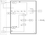
- FIG. 1 is a functional block diagram of the system. The structure which concerns on the surgery assistance system of this embodiment is demonstrated.
- the surgery support system includes a camera 1, a projector 2, a registration tracker 3, and an image processing device 4.
- Camera 1 and projector 2 are unit 5. Therefore, the positional relationship between the camera 1 and the projector 2 is known and stored in the image processing device 4.
- optical characteristics (lens characteristics) of the camera 1 and the projector 2 are known.
- the camera 1 photographs the registration tracker 3.
- the projector 2 projects the target image onto the projection target.
- the target image is an image related to a target inside the projection target, and is acquired based on a medical image acquired separately.
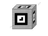
- FIG. 2 is an example of a registration tracker.
- the registration tracker 3 is preferably a polyhedron (see the second embodiment). In the figure, it is a hexahedron.
- the registration tracker 3 When creating a medical image, the registration tracker 3 is installed at an arbitrary position on the body surface (see FIG. 6). However, it is installed at the same position when the target image is projected (see FIG. 7).
- the registration tracker 3 when imaging the registration tracker 3 as a CT image, it is preferable that the registration tracker 3 is a material (for example, wood) harder than the living skin tissue.
- the 3D shape information of the registration tracker 3 is known and stored in the image processing apparatus 4.
- a reflection type registration marker 6 is provided on the surface of the registration tracker 3.
- the registration marker 6 is provided on at least one surface so as to face the camera 1, but it is preferable that the registration marker 6 be provided on a plurality of surfaces as shown (see the second embodiment).
- the positional relationship of the registration marker 6 in the registration tracker 3 is known and stored in the image processing apparatus 4.
- FIG. 3 shows a modification of the registration tracker.
- the registration tracker 3 in FIG. 2 is a hexahedron, whereas the modified example has a plate shape. That is, it need not be a polyhedron.
- the registration marker 6 is provided on the surface of the registration tracker 3, whereas in the modified example, the four corners of the registration tracker 3 function as the registration marker 6.
- the registration tracker is not limited to this as long as the three-dimensional shape information can be acquired and can be identified by the camera.
- the camera coordinate system setting function unit 41 sets a three-dimensional coordinate system viewed from the camera 1 based on the optical characteristics of the camera 1.
- the projector coordinate system setting function unit 42 sets a three-dimensional coordinate system viewed from the projector 2 based on the optical characteristics of the projector 2.
- the registration marker photographing function unit 43 obtains registration marker information Mm (for example, three-dimensional coordinates of four points at the four corners of the marker) in the camera coordinate system based on the photographed image information m m (two-dimensional) of the registration marker 6. get. Furthermore, based on the positional relationship between the registration tracker 3 and the registration marker 6 and the registration marker information Mm in the camera coordinate system, the registration tracker information Mt in the camera coordinate system (for example, 4 at the four corners of the opposing surface). 3D coordinates of the point) are acquired.
- registration marker information Mm for example, three-dimensional coordinates of four points at the four corners of the marker
- the camera 1 identifies the registration markers on the plurality of surfaces. This improves the accuracy of registration.
- the registration tracker information conversion function unit 44 acquires registration tracker information Pt in the projector coordinate system based on the positional relationship between the camera 1 and the projector 2 and the registration tracker information Mt in the camera coordinate system.
- the medical image input function unit 45 inputs registration tracker information CTt of the medical image coordinate system and target information CTg of the medical image coordinate system acquired in advance.
- the target photographed image acquisition function unit 46 calculates the projector based on the positional relationship between the registration tracker information CTt in the medical image coordinate system and the target information CTg in the medical image coordinate system, and the registration tracker information Pt in the projector coordinate system. Get target information Pg of coordinate system.
- Dimensional transform function unit 47 converts the target information of the projector coordinate system from the three-dimensional coordinates Pg in two-dimensional coordinates p g.
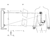
- FIG. 4 is a conceptual diagram of the operation of this system
- FIG. 5 is a processing flow diagram of the system. The operation
- a medical image coordinate system registration tracker information CTt and a medical image coordinate system target information CTg are created by a medical image creation device (see FIG. 6) (step S1).
- Medical images include CT images and MRI images. Three-dimensional information can be obtained by overlapping two-dimensional images in layers.
- FIG. 6 is an operation explanatory diagram when creating a medical image.
- the illustration shows a CT scanning device.
- the registration tracker 3 is installed at an arbitrary position on the body surface.
- the medical image coordinate system registration tracker information CTt and the medical image coordinate system target information CTg are input to the image processing apparatus 4.
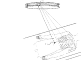
- FIG. 7 is an explanatory diagram of an operation at the time of projecting a target image.
- the installation position of the registration tracker 3 is marked on the patient's body surface.
- the registration tracker 3 is installed at a predetermined position.
- the unit 5 including the camera 1 and the projector 2 is installed so as to correspond to the projection target (predetermined range on the patient body surface) (step S2). More specifically, the projector 2 can project the target image onto the projection target so that the camera 1 can photograph the registration tracker 3.
- the camera 1 photographs the registration tracker 3 installed on the surface of the projection target (step S3).
- the image processing apparatus 4 performs registration based on the image taken by the registration tracker by the camera and the registration tracker information acquired at the same time as acquiring the medical image, and the inside of the projection target (under the body surface) Target information, which is image information related to the target at, is acquired (step S4). Details of the image processing will be described below.
- registration tracker information Mt in the camera coordinate system is acquired based on an image taken by the registration tracker 3 by the camera 1 (step S41).
- the camera 1 identifies the registration marker 6.
- the actual registration DOO marker 6 to form a dimension known square (see FIG. 2) registration preparative marker 6 in the captured image is a two-dimensional form a quadrangle m m was crushed. Based on the degree of deformation, registration marker information Mm (three-dimensional coordinates) in the camera coordinate system is acquired.
- the positional relationship between the registration tracker 3 and the registration marker 6 is known, whereby registration tracker information Mt in the camera coordinate system can be acquired.
- step S42 Furthermore, the positional relationship between the camera 1 and the projector 2 is known, and registration tracker information Pt in the projector coordinate system is acquired (step S42).
- test image may be projected onto the registration tracker 3.
- the positional relationship between the registration tracker information CTt in the medical image coordinate system and the target information CTg in the medical image coordinate system is known, and the target information Pg in the projector coordinate system is acquired (step S43).
- the projection image of the projector 2 is two-dimensional. Therefore, to convert the target information of the projector coordinate system from the three-dimensional coordinates Pg in two-dimensional coordinates p g (step S44).
- the projector 2 based on the 2-dimensional target information p g, projecting a target image on a projection target (step S5).
- the surgeon can easily grasp the internal structure intuitively from the target image. Thereby, an operation is started.
- the surgeon can easily grasp the internal structure intuitively. As a result, the burden on the surgeon for the surgery is greatly reduced, and a reduction in surgical mistakes can be expected.
- FIG. 8 is a functional block diagram of the system of the second embodiment.
- the operation support system includes the camera 1, the projector 2, the registration tracker 3, and the image processing device 4 in common with the first embodiment.
- the second embodiment further includes a unit moving mechanism 7 that moves the unit 5.
- the unit moving mechanism 7 is a rail that moves the unit 5 and a driving device.
- the rail is provided in an annular shape on the upper part of the operating table.
- a partial rail cross section is displayed.
- the projector 2 can project from all directions.
- the image processing apparatus 4 further includes a movement detection function unit 48.
- the movement detection function unit 48 receives movement information from the unit moving mechanism 7 and outputs a control command repeatedly when detecting movement of the camera 1.
- FIG. 9 is a processing flowchart of the system of the second embodiment.
- movement which concerns on the surgery assistance system of this embodiment is demonstrated.
- the operations from steps S1 to S5 are the same as those in the first embodiment.
- the process related to step S6 is further performed.
- the image processing device 4 inputs the movement information output by the unit moving mechanism 7 and repeatedly outputs a control command (step S6).
- the camera 1 images a registration tracker installed on the surface of the projection target (step S3), and the image processing apparatus 4 performs registration and acquires target information for projection (step S4).
- the projector 2 projects the target image onto the projection target (step S5), and a series of operations are repeated.
- the registration tracker 3 is a polyhedron, and there are registration markers on a plurality of surfaces (see FIG. 2). When the unit 5 moves greatly, the camera 1 recognizes the registration marker on the other surface, and the image processing apparatus 4 performs registration again.
- the position of the operator may change, and the operator may become an obstacle and the target image may not be projected onto the projection target.
- the unit 5 is moved as the operator position changes. Since registration is performed in real time, the target image can be projected again from another direction. Thereby, it can be avoided that the surgeon becomes an obstacle to projection.
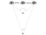
- FIG. 10 is a diagram illustrating the principle of a pseudo three-dimensional image.
- FIG. 11 is an explanatory diagram of an operation for obtaining a pseudo 3D image.
- the projection direction from the projector 2 changes.
- a phenomenon similar to visual motion parallax occurs. That is, the object in the deep part from the body surface moves little, and the object near the body surface moves greatly.
- the movement of the sternum is larger than the movement of the spine. Thereby, the depth can be intuitively recognized.
- the projection image from the projector 2 is two-dimensional information
- a pseudo three-dimensional image is obtained by the movement of the unit 5.
- FIG. 12 is a functional block diagram according to a modification.
- the movement detection function unit 48 inputs movement information from the unit moving mechanism 7, whereas in FIG. 12, the movement detection function unit 48 inputs movement information from the registration marker photographing function unit 43.
- the image processing device 4 repeatedly outputs a control command based on the change in the captured image by the camera 1 (step S6).
- the unit is moved by the unit moving mechanism 7, but the unit 5 can be made portable by downsizing the camera and the projector.
- the same effect as in the second embodiment can be obtained when the surgical assistant moves with the unit 5.
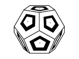
- FIG. 13 shows a modification of the registration tracker.
- the registration tracker 3 is preferably a polyhedron.
- it is a hexahedron
- FIG. 13 it is a dodecahedron. This improves the registration accuracy.
- the present invention is a surgery support system, but is not limited to medical treatment or surgery, and can be applied to a case where the objective is to project an internal structure by a projector.
- FIG. 14 is an example of application to a non-destructive inspection of a projector system.
- the system configuration and system processing flow are the same as those of the surgery support system.
- the internal rebar may be damaged even if there is no damage to the concrete structure by visual confirmation.
- ultrasonic inspection of the reinforcing bar is performed from the concrete surface to confirm that the reinforcing bar is healthy. The operation of the application example will be described below.
- 3D CAD information of concrete structures and reinforcements is created in advance based on the design drawings. Further, the installation position of the registration tracker 3 is determined in advance and added to the three-dimensional CAD information (step S1). As a result, the positional relationship between the registration tracker information CDt in the three-dimensional CAD coordinate system and the target information CDg in the three-dimensional CAD coordinate system becomes known.
- ⁇ Registration tracker 3 is installed at a predetermined position on the concrete structure surface. Further, the unit 5 including the camera 1 and the projector 2 is installed so as to correspond to the projection target (inspection range of the concrete structure) (step S2). More specifically, the projector 2 can project the target image onto the projection target so that the camera 1 can photograph the registration tracker 3. Whether the camera 1 is properly capturing the registration tracker 3 may be confirmed by a monitor.
- the bar arrangement image is projected onto the concrete structure.
- the camera 1 images the registration tracker 3 installed on the surface of the projection target (step S3), and the image processing apparatus 4 performs registration and acquires target information for projection (step S4).
- 2 projects a target image (reinforcement image) onto a projection target (step S5).
- a pseudo three-dimensional image may be obtained by moving the unit 5 (step S6).
Landscapes
- Health & Medical Sciences (AREA)
- Surgery (AREA)
- Life Sciences & Earth Sciences (AREA)
- Heart & Thoracic Surgery (AREA)
- Molecular Biology (AREA)
- Oral & Maxillofacial Surgery (AREA)
- Engineering & Computer Science (AREA)
- Biomedical Technology (AREA)
- Nuclear Medicine, Radiotherapy & Molecular Imaging (AREA)
- Medical Informatics (AREA)
- Pathology (AREA)
- Animal Behavior & Ethology (AREA)
- General Health & Medical Sciences (AREA)
- Public Health (AREA)
- Veterinary Medicine (AREA)
- Controls And Circuits For Display Device (AREA)
- Apparatus For Radiation Diagnosis (AREA)
Abstract
全自動でプロジェクタのレジストレーションを行うことができる手術支援システムを提供する。手術支援システムは、カメラ1と、プロジェクタ2と、レジストレーショントラッカー3と、画像処理装置4とを備える。医療画像は予め取得されている。レジストレーショントラッカー3が体表の所定位置に設置される。カメラ1は、レジストレーショントラッカー3を撮影する。画像処理装置4は、カメラ1によるレジストレーショントラッカー3の撮影画像mmと、予め医療画像を取得するときと同時に取得されたレジストレーショントラッカー情報Ctと、基づいて、レジストレーションを行い、プロジェクタが被投影対象に投影するためのターゲット情報pgを取得する。プロジェクタ2は、ターゲット情報pgに基づいて、ターゲット画像を被投影対象に投影する。
Description
本発明は、プロジェクタシステムを活用した手術支援技術である。
近年、プロジェクトマッピングに係る技術が注目されている。東京駅駅舎や大阪城などの壁面に、非現実的な映像を投影することにより、幻想的な空間を演出できる。また、ビル壁面に芸術的な映像を投影することにより、都市景観に変化を付けることができる。プロジェクトマッピングを利用したイベントは、観客の目を楽しませ、大きな集客力を見込める。これにより、大きな経済効果を期待できる。
また、非現実的な映像を投影し、観客の目を楽しませることができる為、娯楽の分野にも適用されている(特許文献1)。
一方で、医療の分野でもプロジェクタを用いた手術支援技術の研究が行われている。CTやMRIで撮影した医療画像を体表や臓器に投影する。投影により直感的な内部構造の把握を容易にし,手術ミスの低減が見込める。
このとき、投影画像と被投影対象の位置合わせ(レジストレーション)が重要となる。レジストレーションのやり方は様々の方法が検討され、確立した技術がない。
例えば、予め医療画像と一緒に体表の画像も取得し、体表画像を体表に投影し、位置合わせを行い、位置の一致を確認した後、ターゲット画像(医療画像に基づく投影対象画像)を投影する。
ところで、上述のプロジェクトマッピング技術の実務では、専門知識を持った映像技術者が特殊な機械を用いている。一方で、手術者は、映像技術に関する専門知識が乏しい場合も多い。レジストレーションに不具合があると、適切な手術支援ができないだけでなく、逆に、手術現場が混乱するおそれもある。
手術に少しの失敗も許されない。手術者は想像以上の緊張を強いられる。したがって、少しの追加負担も手術者に課すことは好ましくない。
本発明は上記課題を解決するものであり、全自動でプロジェクタのレジストレーションを行う手術支援システムを提供することを目的とする。
上記課題を解決する本発明の手術支援システムは、カメラと、プロジェクタと、被投影対象の表面に設置されるレジストレーショントラッカーと、画像処理装置と、を備え、前記画像処理装置は、前記カメラによるレジストレーショントラッカーの撮影画像と、予め医療画像を取得するときと同時に取得されたレジストレーショントラッカー情報と、基づいて、レジストレーションを行い、前記プロジェクタが被投影対象に投影するためのターゲット情報を取得する。
上記課題を解決する本発明の手術支援システムは、カメラと、プロジェクタと、被投影対象の表面に設置されるレジストレーショントラッカーと、画像処理装置と、を備え、前記画像処理装置は、前記カメラから見た3次元座標系を設定するカメラ座標系設定機能部と、前記プロジェクタから見た3次元座標系を設定するプロジェクタ座標系設定機能部と、前記カメラとプロジェクタとの位置関係と、前記カメラ座標系のレジストレーショントラッカー情報と、に基づいて、前記プロジェクタ座標系のレジストレーショントラッカー情報を取得するレジストレーショントラッカー情報変換機能部と、予め取得された医療画像座標系のレジストレーショントラッカー情報と医療画像座標系のターゲット情報とを入力する医療画像入力機能部と、前記医療画像座標系のレジストレーショントラッカー情報と医療画像座標系のターゲット情報との位置関係と、前記プロジェクタ座標系のレジストレーショントラッカー情報と、に基づいて、プロジェクタ座標系のターゲット情報を取得するターゲット撮影画像取得機能部と、プロジェクタ座標系のターゲット情報を3次元座標から2次元座標に変換する次元変換機能部と、を有する。
上記構成により全自動でプロジェクタのレジストレーションを行うことができる。
上記発明において、好ましくは、前記カメラは、前記レジストレーショントラッカーを撮影し、前記画像処理装置は、前記カメラによるレジストレーショントラッカーの撮影画像に基づいて、前記カメラ座標系のレジストレーショントラッカー情報を取得するレジストレーショントラッカー撮影機能部を有する。
上記発明において、好ましくは、前記レジストレーショントラッカーにはレジストレーションマーカが設けられ、前記カメラは、前記レジストレーションマーカを撮影し、前記画像処理装置は、レジストレーションマーカの撮影画像に基づいて、前記カメラ座標系のレジストレーションマーカ情報を取得し、前記レジストレーショントラッカーとレジストレーションマーカとの位置関係と、前記カメラ座標系のレジストレーションマーカ情報と、に基づいて、前記カメラ座標系のレジストレーショントラッカー情報を取得するレジストレーションマーカ撮影機能部を有する。
上記発明において、好ましくは、前記プロジェクタは、前記ターゲット情報に基づいて、被投影対象内部にあるターゲットに関する画像であるターゲット画像を被投影対象に投影する。
上記発明において、好ましくは、前記医療画像座標系のレジストレーショントラッカー情報は、該レジストレーショントラッカーが被投影対象の表面の所定位置に設置された状態で取得される。
上記本発明の手術支援システムは、前記カメラとプロジェクタとを含むユニットを移動するユニット移動機構を更に備える。
上記発明において、前記レジストレーショントラッカーは多面体である。
上記発明において、前記画像処理装置は、前記カメラの移動を検出すると、繰り返し制御指令を出力する移動検出機能部を有する。
これにより、多方向からターゲット画像を投影できる。これにより、手術者が投影の障害となることを避けることができる。さらに、疑似3次元画像が得られる。
上記課題を解決する本発明のプロジェクタシステムは、カメラと、プロジェクタと、被投影対象の表面に設置されるレジストレーショントラッカーと、画像処理装置と、を備え、前記画像処理装置は、前記カメラから見た3次元座標系を設定するカメラ座標系設定機能部と、前記プロジェクタから見た3次元座標系を設定するプロジェクタ座標系設定機能部と、前記カメラとプロジェクタとの位置関係と、前記カメラ座標系のレジストレーショントラッカー情報と、に基づいて、前記プロジェクタ座標系のレジストレーショントラッカー情報を取得するレジストレーショントラッカー情報変換機能部と、予め取得された事前画像座標系のレジストレーショントラッカー情報と事前画像座標系のターゲット情報とを入力する事前画像入力機能部と、前記事前画像座標系のレジストレーショントラッカー情報と事前画像座標系のターゲット情報との位置関係と、前記プロジェクタ座標系のレジストレーショントラッカー情報と、に基づいて、プロジェクタ座標系のターゲット情報を取得するターゲット撮影画像取得機能部と、プロジェクタ座標系のターゲット情報を3次元座標から2次元座標に変換する次元変換機能部と、を有する。
本発明のプロジェクタシステムは、手術支援以外の用途にも適用可能である。
上記課題を解決する本発明の医療画像投影方法は、医療画像作成装置が、ターゲットに係る医療画像作成と同時にレジストレーショントラッカー情報を作成し、カメラと、プロジェクタと、被投影対象の表面に設置されたレジストレーショントラッカーと、画像処理装置と、を備える手術支援システムのうち、該カメラと該プロジェクタとを含むユニットが、被投影対象に対応するように設置され、前記カメラが、被投影対象の表面に設置されたレジストレーショントラッカーを撮影し、前記画像処理装置が、前記カメラによるレジストレーショントラッカーの撮影画像と、予め医療画像を取得するときと同時に取得されたレジストレーショントラッカー情報と、基づいて、レジストレーションを行い、被投影対象内部にあるターゲットに関する画像情報であるターゲット情報を取得し、前記プロジェクタが、前記ターゲット情報に基づいて、ターゲット画像を被投影対象に投影する。
上記課題を解決する本発明の医療画像投影方法は、医療画像作成装置が、医療画像座標系のレジストレーショントラッカー情報と医療画像座標系のターゲット情報とを予め作成し、カメラと、プロジェクタと、被投影対象の表面に設置されたレジストレーショントラッカーと、画像処理装置と、を備える手術支援システムのうち、該カメラと該プロジェクタとを含むユニットが、被投影対象に対応するように設置され、前記カメラが、被投影対象の表面に設置されたレジストレーショントラッカーを撮影し、前記画像処理装置が、前記カメラによるレジストレーショントラッカーの撮影画像に基づいて、前記カメラ座標系のレジストレーショントラッカー情報を取得し、前記カメラとプロジェクタとの位置関係と、前記カメラ座標系のレジストレーショントラッカー情報と、に基づいて、前記プロジェクタ座標系のレジストレーショントラッカー情報を取得し、前記医療画像座標系のレジストレーショントラッカー情報と医療画像座標系のターゲット情報との位置関係と、前記プロジェクタ座標系のレジストレーショントラッカー情報と、に基づいて、プロジェクタ座標系のターゲット情報を取得し、プロジェクタ座標系のターゲット情報を3次元座標から2次元座標に変換し、前記プロジェクタが、前記2次元ターゲット情報に基づいて、ターゲット画像を被投影対象に投影する。
上記発明において、前記カメラと該プロジェクタとを含むユニットが移動され、前記ユニット移動の度に、前記カメラによる撮影と、前記画像処理装置による画像処理と、前記プロジェクタによる投影と、が繰り返される。
本発明の手術支援システムは、全自動でプロジェクタのレジストレーションを行うことができる。その結果、手術者の負担が大幅に軽減される。
<第1実施形態>
~構成~
図1は、システムの機能ブロック図である。本実施形態の手術支援システムに係る構成について説明する。手術支援システムは、カメラ1と、プロジェクタ2と、レジストレーショントラッカー3と、画像処理装置4とを備える。
~構成~
図1は、システムの機能ブロック図である。本実施形態の手術支援システムに係る構成について説明する。手術支援システムは、カメラ1と、プロジェクタ2と、レジストレーショントラッカー3と、画像処理装置4とを備える。
カメラ1とプロジェクタ2はユニット5になっている。したがって、カメラ1とプロジェクタ2の位置関係は既知であり、画像処理装置4に記憶されている。
カメラ1とプロジェクタ2の光学的特性(レンズ特性)は既知である。
カメラ1は、レジストレーショントラッカー3を撮影する。プロジェクタ2はターゲット画像を被投影対象に投影する。ターゲット画像は、被投影対象内部にあるターゲットに関する画像であり、別途取得される医療画像に基づき取得される。
図2は、レジストレーショントラッカーの一例である。レジストレーショントラッカー3は多面体であることが好ましい(第2実施形態参照)。図示では六面体である。
医療画像作成時、レジストレーショントラッカー3は、体表の任意位置に設置される(図6参照)。ただし、ターゲット画像投影時も、同じ位置に設置される(図7参照)。
なお、CT画像としてレジストレーショントラッカー3を撮影する場合には、レジストレーショントラッカー3は生体皮膚組織より固めの素材(例えば木材)であることが好ましい。
レジストレーショントラッカー3の3次元形状情報は既知であり、画像処理装置4に記憶されている。
レジストレーショントラッカー3の表面には反射型のレジストレーションマーカ6が設けられている。レジストレーションマーカ6は、カメラ1に対向するように少なくとも一面に設けられるが、図示のように複数面に設けられと尚よい(第2実施形態参照)。
レジストレーショントラッカー3におけるレジストレーションマーカ6の位置関係は既知であり、画像処理装置4に記憶されている。
図3は、レジストレーショントラッカーの変形例である。図2のレジストレーショントラッカー3が六面体であるのに対し、変形例はプレート形状である。すなわち多面体でなくとも良い。また、図2では、レジストレーショントラッカー3の表面にレジストレーションマーカ6が設けられているのに対し、変形例では、レジストレーショントラッカー3の四隅がレジストレーションマーカ6として機能する。
すなわち、レジストレーショントラッカーは、3次元形状情報が取得でき、かつ、カメラにより識別できれば、これらに限定されない。
図1に戻り、画像処理装置4の各機能部41~47について説明する。
カメラ座標系設定機能部41は、カメラ1の光学的特性に基づき、カメラ1から見た3次元座標系を設定する。
プロジェクタ座標系設定機能部42は、プロジェクタ2の光学的特性に基づき、プロジェクタ2から見た3次元座標系を設定する。
レジストレーションマーカ撮影機能部43は、レジストレーションマーカ6の撮影画像情報mm(2次元)に基づいて、カメラ座標系のレジストレーションマーカ情報Mm(例えばマーカの四隅の4点の3次元座標)を取得する。さらに、レジストレーショントラッカー3とレジストレーションマーカ6との位置関係と、カメラ座標系のレジストレーションマーカ情報Mmと、に基づいて、カメラ座標系のレジストレーショントラッカー情報Mt(例えば対向する一面の四隅の4点の3次元座標)を取得する。
なお、説明の便宜のため、レジストレーショントラッカーの一面のみを用いたが、複数面にレジストレーションマーカがある場合(図2参照)は、カメラ1は、複数面のレジストレーションマーカをそれぞれ識別する。これにより、レジストレーションの精度が向上する。
レジストレーショントラッカー情報変換機能部44は、カメラ1とプロジェクタ2との位置関係と、カメラ座標系のレジストレーショントラッカー情報Mtと、に基づいて、プロジェクタ座標系のレジストレーショントラッカー情報Ptを取得する。
医療画像入力機能部45は、予め取得された医療画像座標系のレジストレーショントラッカー情報CTtと医療画像座標系のターゲット情報CTgとを入力する。
ターゲット撮影画像取得機能部46は、医療画像座標系のレジストレーショントラッカー情報CTtと医療画像座標系のターゲット情報CTgとの位置関係と、プロジェクタ座標系のレジストレーショントラッカー情報Ptと、に基づいて、プロジェクタ座標系のターゲット情報Pgを取得する。
次元変換機能部47は、プロジェクタ座標系のターゲット情報を3次元座標Pgから2次元座標pgに変換する。
~動作~
図4は本システムの動作概念図であり、図5は、システムの処理フロー図である。本実施形態の手術支援システムに係る動作について説明する。
図4は本システムの動作概念図であり、図5は、システムの処理フロー図である。本実施形態の手術支援システムに係る動作について説明する。
予め、医療画像作成装置(図6参照)により、医療画像座標系のレジストレーショントラッカー情報CTtと医療画像座標系のターゲット情報CTgとを作成する(ステップS1)。医療画像には、CT画像やMRI画像等がある。2次元画像を何層にも重ねることで、3次元情報が得られる。
図6は、医療画像作成時の動作説明図である。図示はCTスキャン装置である。CTスキャン時に、レジストレーショントラッカー3を体表の任意位置に設置する。ただし、ターゲット画像投影時のレジストレーショントラッカー3の設置位置(図7参照)と、同じ位置とする必要がある。したがって、ターゲット画像投影の障害とならないように考慮する。
通常、手術の前日に医療画像を作成する。医療画像作成後、レジストレーショントラッカー3の設置位置を体表にマークした後、レジストレーショントラッカー3を取り外す。
医療画像座標系のレジストレーショントラッカー情報CTtと医療画像座標系のターゲット情報CTgを画像処理装置4に入力する。
次いで、手術時の動作について説明する。図7は、ターゲット画像投影時の動作説明図である。
患者の体表には、レジストレーショントラッカー3の設置位置がマークされている。レジストレーショントラッカー3を所定の位置に設置する。
カメラ1とプロジェクタ2とを含むユニット5を被投影対象(患者体表の所定範囲)に対応するように設置する(ステップS2)。より具体的には、カメラ1がレジストレーショントラッカー3を撮影可能なように、プロジェクタ2がターゲット画像を被投影対象に投影可能なようにする。
カメラ1は、被投影対象の表面に設置されたレジストレーショントラッカー3を撮影する(ステップS3)。
画像処理装置4は、カメラによるレジストレーショントラッカーの撮影画像と、医療画像を取得するときと同時に取得されたレジストレーショントラッカー情報と、基づいて、レジストレーションを行い、被投影対象内部(体表下)にあるターゲットに関する画像情報であるターゲット情報を取得する(ステップS4)。以下、画像処理の詳細について説明する。
まず、カメラ1によるレジストレーショントラッカー3の撮影画像に基づいて、カメラ座標系のレジストレーショントラッカー情報Mtを取得する(ステップS41)。
カメラ1はレジストレーショントマーカ6を識別する。実際のレジストレーショントマーカ6は寸法既知の正方形を形成する(図2参照)のに対し、2次元である撮影画像におけるレジストレーショントマーカ6は押し潰された四角形mmを形成する。この変形程度に基づいて、カメラ座標系のレジストレーションマーカ情報Mm(3次元座標)を取得する。
また、レジストレーショントラッカー3とレジストレーションマーカ6との位置関係は既知であり、これにより、カメラ座標系のレジストレーショントラッカー情報Mtを取得できる。
さらに、カメラ1とプロジェクタ2との位置関係は既知であり、プロジェクタ座標系のレジストレーショントラッカー情報Ptを取得する(ステップS42)。
これにより、レジストレーションが完了する。確認のために、テスト画像をレジストレーショントラッカー3に投影しても良い。
医療画像座標系のレジストレーショントラッカー情報CTtと医療画像座標系のターゲット情報CTgとの位置関係は既知であり、プロジェクタ座標系のターゲット情報Pgを取得する(ステップS43)。
プロジェクタ2の投影画像は2次元である。したがって、プロジェクタ座標系のターゲット情報を3次元座標Pgから2次元座標pgに変換する(ステップS44)。
プロジェクタ2は、2次元ターゲット情報pgに基づいて、ターゲット画像を被投影対象に投影する(ステップS5)。
手術者は、ターゲット画像により直感的に内部構造を容易に把握できる。これにより、手術が開始される。
~効果~
以上のように、本システムでは、全自動でプロジェクタのレジストレーションを行うことができる。レジストレーションの不具合で、手術現場が混乱するおそれはない。その結果、システム導入に対する手術者の負担が大幅に軽減され、手術者は手術に集中できる。
以上のように、本システムでは、全自動でプロジェクタのレジストレーションを行うことができる。レジストレーションの不具合で、手術現場が混乱するおそれはない。その結果、システム導入に対する手術者の負担が大幅に軽減され、手術者は手術に集中できる。
さらに、ターゲット画像の支援により、手術者は直感的に内部構造を容易に把握できる。その結果、手術に対する手術者の負担は大幅に軽減され、手術ミスの低減が期待できる。
<第2実施形態>
~構成・動作~
図8は、第2実施形態のシステムの機能ブロック図である。本実施形態の手術支援システムに係る構成について説明する。手術支援システムが、カメラ1と、プロジェクタ2と、レジストレーショントラッカー3と、画像処理装置4とを備える点は、第1実施形態と共通する。第2実施形態は更に、ユニット5を移動するユニット移動機構7を備える。
~構成・動作~
図8は、第2実施形態のシステムの機能ブロック図である。本実施形態の手術支援システムに係る構成について説明する。手術支援システムが、カメラ1と、プロジェクタ2と、レジストレーショントラッカー3と、画像処理装置4とを備える点は、第1実施形態と共通する。第2実施形態は更に、ユニット5を移動するユニット移動機構7を備える。
たとえば、図7において、ユニット移動機構7はユニット5を移動するレールと駆動装置である。レールは、手術台上部に環状に設けられている。理解のため、一部レール断面を表示する。ユニット5がレール上を一周することにより、プロジェクタ2は全方向から投影できる。
画像処理装置4は、さらに、移動検出機能部48を有する。移動検出機能部48は、ユニット移動機構7から移動情報を入力し、カメラ1の移動を検出すると、繰り返し制御指令を出力する。
図9は、第2実施形態のシステムの処理フロー図である。本実施形態の手術支援システムに係る動作について説明する。ステップS1~S5までの動作は、第1実施形態と共通する。第2実施形態は更に、ステップS6に係る処理を行う。
ユニット移動機構7がユニット5を移動すると、プロジェクタ2の位置が変わり、再度レジストレーションをする必要がある。画像処理装置4は、ユニット移動機構7が出力する移動情報を入力し、繰り返し制御指令を出力する(ステップS6)。
再度、カメラ1は、被投影対象の表面に設置されたレジストレーショントラッカーを撮影し(ステップS3)、画像処理装置4は、レジストレーションを行い、投影のためのターゲット情報を取得し(ステップS4)、プロジェクタ2は、ターゲット画像を被投影対象に投影する(ステップS5)一連の動作が繰り返される。
レジストレーショントラッカー3は多面体であり、複数面にレジストレーションマーカがある(図2参照)。ユニット5が大きく移動した場合、カメラ1は別面のレジストレーションマーカを認識し、画像処理装置4は再度レジストレーションをおこなう。
~効果~
手術中、手術者の位置が変わることもあり、手術者が障害となって、ターゲット画像を被投影対象に投影できないおそれもある。
手術中、手術者の位置が変わることもあり、手術者が障害となって、ターゲット画像を被投影対象に投影できないおそれもある。
本実施形態では、手術者位置の変動に伴い、ユニット5を移動する。リアルタイムにレジストレーションを行うため、再度、別の方向からターゲット画像を投影できる。これにより、手術者が投影の障害となることを避けることができる。
さらに、本実施形態では、疑似3次元画像が得られる。以下詳述する。
図10は、疑似3次元画像の原理説明図である。同一視線上に2つの対象物があり、視線を左右に動かす場合、近くの対象物は大きく動くように見え、遠くの対象物は小さく動くように見える。この現象は、視覚の運動視差と呼ばれる。これにより、奥行きが認識可能となる。
図11は、疑似3次元画像を得る動作の説明図である。ユニット5が移動することにより、プロジェクタ2からの投影方向が変化する。これにより、視覚の運動視差と同様な現象が生じる。すなわち、体表から深部にある対象は動きが小さく、体表近傍にある対象は大きく動く。図示の例では、背骨の動きに比べて胸骨の動きが大きい。これにより、直感的に奥行きを認識できる。
プロジェクタ2からの投影画像は2次元情報であるが、ユニット5の移動により、疑似3次元画像が得られる。
~変形例~
図12は、変形例に係る機能ブロック図である。図8において、移動検出機能部48は、ユニット移動機構7から移動情報を入力するのに対し、図12では、移動検出機能部48は、レジストレーションマーカ撮影機能部43から移動情報を入力する。
図12は、変形例に係る機能ブロック図である。図8において、移動検出機能部48は、ユニット移動機構7から移動情報を入力するのに対し、図12では、移動検出機能部48は、レジストレーションマーカ撮影機能部43から移動情報を入力する。
すなわち、ユニット5が移動するとカメラ1の視野も移動し、カメラ1は既知のレジストレーションマーカを認識できなくなる。画像処理装置4は、カメラ1による撮影画像の変化に基づいて、繰り返し制御指令を出力する(ステップS6)。
図7および図8では、ユニット移動機構7によりユニットを移動したが、カメラおよびプロジェクタを小型化することにより、ユニット5をポータブルとすることができる。たとえば、手術補助者がユニット5を持って移動することで、第2実施形態と同様の効果が得られる。
図13はレジストレーショントラッカーの変形例である。第2実施形態においては、レジストレーショントラッカー3は多面体であることが好ましい旨について説明した。図2では六面体であるのに対し、図13では十二面体である。これによりレジストレーションの精度が向上する。
<第3実施形態>
本発明は手術支援システムであるが、医療や手術に限定されず、プロジェクタにより内部構造を投影することを目的とする場合に、適用可能である。
本発明は手術支援システムであるが、医療や手術に限定されず、プロジェクタにより内部構造を投影することを目的とする場合に、適用可能である。
図14は、プロジェクタシステムの非破壊検査への適用例である。システム構成やシステムの処理フローは、手術支援システムと同様である。
たとえば、地震後、目視確認ではコンクリート構造物に被害がない場合でも、内部の鉄筋が損傷している場合がある。これに対し、コンクリート表面から、鉄筋の超音波探査を行い、鉄筋が健全であることを確かめる。以下、適用例の動作について説明する。
まず、コンクリート構造物および配筋の3次元CAD情報を、設計図面に基づいて事前に作成しておく。さらに、レジストレーショントラッカー3の設置位置を予め決めておき、3次元CAD情報に追加する(ステップS1)。これにより、3次元CAD座標系のレジストレーショントラッカー情報CDtと3次元CAD座標系のターゲット情報CDgとの位置関係は既知となる。
コンクリート構造物表面の所定位置にレジストレーショントラッカー3を設置する。また、カメラ1とプロジェクタ2とを含むユニット5を被投影対象(コンクリート構造物の調査範囲)に対応するように設置する(ステップS2)。より具体的には、カメラ1がレジストレーショントラッカー3を撮影可能なように、プロジェクタ2がターゲット画像を被投影対象に投影可能なようにする。カメラ1がレジストレーショントラッカー3を適切に撮影しているか、モニタにより確認しても良い。
以上の準備が終わり次第、配筋画像をコンクリート構造物に投影する。カメラ1は、被投影対象の表面に設置されたレジストレーショントラッカー3を撮影し(ステップS3)、画像処理装置4は、レジストレーションを行い、投影用のターゲット情報を取得し(ステップS4)、プロジェクタ2は、ターゲット画像(配筋画像)を被投影対象に投影する(ステップS5)。
さらに、ユニット5の移動により、疑似3次元画像を得ても良い(ステップS6)。
投影画像を参照しながら、対象鉄筋位置を推定し、超音波探査をおこなう。配筋を可視化することで、調査対象を特定でき、探査精度が向上する。
調査現場では、全自動でプロジェクタのレジストレーションを行うことができるので、投影作業に手間取ることなく、調査員は調査に集中できる。
1 カメラ
2 プロジェクタ
3 レジストレーショントラッカー
4 画像処理装置
5 ユニット
6 レジストレーションマーカ
7 ユニット移動機構
41 カメラ座標系設定機能部
42 プロジェクタ座標系設定機能部
43 レジストレーションマーカ撮影機能部
44 レジストレーショントラッカー情報変換機能部
45 医療画像入力機能部
46 ターゲット撮影画像取得機能部
47 次元変換機能部
48 移動検出機能部
2 プロジェクタ
3 レジストレーショントラッカー
4 画像処理装置
5 ユニット
6 レジストレーションマーカ
7 ユニット移動機構
41 カメラ座標系設定機能部
42 プロジェクタ座標系設定機能部
43 レジストレーションマーカ撮影機能部
44 レジストレーショントラッカー情報変換機能部
45 医療画像入力機能部
46 ターゲット撮影画像取得機能部
47 次元変換機能部
48 移動検出機能部
Claims (13)
- カメラと、プロジェクタと、被投影対象の表面に設置されるレジストレーショントラッカーと、画像処理装置と、を備え、
前記画像処理装置は、
前記カメラによるレジストレーショントラッカーの撮影画像と、予め医療画像を取得するときと同時に取得されたレジストレーショントラッカー情報と、基づいて、レジストレーションを行い、
前記プロジェクタが被投影対象に投影するためのターゲット情報を取得する
ことを特徴とする手術支援システム。 - カメラと、プロジェクタと、被投影対象の表面に設置されるレジストレーショントラッカーと、画像処理装置と、を備え、
前記画像処理装置は、
前記カメラから見た3次元座標系を設定するカメラ座標系設定機能部と、
前記プロジェクタから見た3次元座標系を設定するプロジェクタ座標系設定機能部と、
前記カメラとプロジェクタとの位置関係と、前記カメラ座標系のレジストレーショントラッカー情報と、に基づいて、前記プロジェクタ座標系のレジストレーショントラッカー情報を取得するレジストレーショントラッカー情報変換機能部と、
予め取得された医療画像座標系のレジストレーショントラッカー情報と医療画像座標系のターゲット情報とを入力する医療画像入力機能部と、
前記医療画像座標系のレジストレーショントラッカー情報と医療画像座標系のターゲット情報との位置関係と、前記プロジェクタ座標系のレジストレーショントラッカー情報と、に基づいて、プロジェクタ座標系のターゲット情報を取得するターゲット撮影画像取得機能部と、
プロジェクタ座標系のターゲット情報を3次元座標から2次元座標に変換する次元変換機能部と、
を有する
ことを特徴とする手術支援システム。 - 前記カメラは、前記レジストレーショントラッカーを撮影し、
前記画像処理装置は、
前記カメラによるレジストレーショントラッカーの撮影画像に基づいて、前記カメラ座標系のレジストレーショントラッカー情報を取得するレジストレーショントラッカー撮影機能部
を有する
ことを特徴とする請求項1または2記載の手術支援システム。 - 前記レジストレーショントラッカーにはレジストレーションマーカが設けられ、
前記カメラは、前記レジストレーションマーカを撮影し、
前記画像処理装置は、
レジストレーションマーカの撮影画像に基づいて、前記カメラ座標系のレジストレーションマーカ情報を取得し、前記レジストレーショントラッカーとレジストレーションマーカとの位置関係と、前記カメラ座標系のレジストレーションマーカ情報と、に基づいて、前記カメラ座標系のレジストレーショントラッカー情報を取得するレジストレーションマーカ撮影機能部
を有する
ことを特徴とする請求項1または2記載の手術支援システム。 - 前記プロジェクタは、前記ターゲット情報に基づいて、被投影対象内部にあるターゲットに関する画像であるターゲット画像を被投影対象に投影する
ことを特徴とする請求項1または2記載の手術支援システム。 - 前記医療画像座標系のレジストレーショントラッカー情報は、該レジストレーショントラッカーが被投影対象の表面の所定位置に設置された状態で取得される
ことを特徴とする請求項1または2記載の手術支援システム。 - 前記カメラとプロジェクタとを含むユニットを移動するユニット移動機構
を更に備える
ことを特徴とする請求項1~6いずれかに記載の手術支援システム。 - 前記レジストレーショントラッカーは多面体である
ことを特徴とする請求項1~7いずれかに記載の手術支援システム。 - 前記画像処理装置は、
前記カメラの移動を検出すると、繰り返し制御指令を出力する移動検出機能部
を有する
ことを特徴とする請求項1~8いずれかに記載の手術支援システム。 - カメラと、プロジェクタと、被投影対象の表面に設置されるレジストレーショントラッカーと、画像処理装置と、を備え、
前記画像処理装置は、
前記カメラから見た3次元座標系を設定するカメラ座標系設定機能部と、
前記プロジェクタから見た3次元座標系を設定するプロジェクタ座標系設定機能部と、
前記カメラとプロジェクタとの位置関係と、前記カメラ座標系のレジストレーショントラッカー情報と、に基づいて、前記プロジェクタ座標系のレジストレーショントラッカー情報を取得するレジストレーショントラッカー情報変換機能部と、
予め取得された事前画像座標系のレジストレーショントラッカー情報と事前画像座標系のターゲット情報とを入力する事前画像入力機能部と、
前記事前画像座標系のレジストレーショントラッカー情報と事前画像座標系のターゲット情報との位置関係と、前記プロジェクタ座標系のレジストレーショントラッカー情報と、に基づいて、プロジェクタ座標系のターゲット情報を取得するターゲット撮影画像取得機能部と、
プロジェクタ座標系のターゲット情報を3次元座標から2次元座標に変換する次元変換機能部と、
を有する
ことを特徴とするプロジェクタシステム。 - 医療画像作成装置が、ターゲットに係る医療画像作成と同時にレジストレーショントラッカー情報を作成し、
カメラと、プロジェクタと、被投影対象の表面に設置されたレジストレーショントラッカーと、画像処理装置と、を備える手術支援システムのうち、該カメラと該プロジェクタとを含むユニットが、被投影対象に対応するように設置され、
前記カメラが、被投影対象の表面に設置されたレジストレーショントラッカーを撮影し、
前記画像処理装置が、
前記カメラによるレジストレーショントラッカーの撮影画像と、予め医療画像を取得するときと同時に取得されたレジストレーショントラッカー情報と、基づいて、レジストレーションを行い、
被投影対象内部にあるターゲットに関する画像情報であるターゲット情報を取得し、
前記プロジェクタが、前記ターゲット情報に基づいて、ターゲット画像を被投影対象に投影する
ことを特徴とする医療画像投影方法。 - 医療画像作成装置が、医療画像座標系のレジストレーショントラッカー情報と医療画像座標系のターゲット情報とを予め作成し、
カメラと、プロジェクタと、被投影対象の表面に設置されたレジストレーショントラッカーと、画像処理装置と、を備える手術支援システムのうち、該カメラと該プロジェクタとを含むユニットが、被投影対象に対応するように設置され、
前記カメラが、被投影対象の表面に設置されたレジストレーショントラッカーを撮影し、
前記画像処理装置が、
前記カメラによるレジストレーショントラッカーの撮影画像に基づいて、前記カメラ座標系のレジストレーショントラッカー情報を取得し、
前記カメラとプロジェクタとの位置関係と、前記カメラ座標系のレジストレーショントラッカー情報と、に基づいて、前記プロジェクタ座標系のレジストレーショントラッカー情報を取得し、
前記医療画像座標系のレジストレーショントラッカー情報と医療画像座標系のターゲット情報との位置関係と、前記プロジェクタ座標系のレジストレーショントラッカー情報と、に基づいて、プロジェクタ座標系のターゲット情報を取得し、
プロジェクタ座標系のターゲット情報を3次元座標から2次元座標に変換し、
前記プロジェクタが、前記2次元ターゲット情報に基づいて、ターゲット画像を被投影対象に投影する
ことを特徴とする医療画像投影方法。 - 前記カメラと該プロジェクタとを含むユニットが移動され、
前記ユニット移動の度に、
前記カメラによる撮影と、前記画像処理装置による画像処理と、前記プロジェクタによる投影と、が繰り返される
ことを特徴とする請求項11または12記載の医療画像投影方法。
Priority Applications (2)
| Application Number | Priority Date | Filing Date | Title |
|---|---|---|---|
| PCT/JP2014/061160 WO2015162665A1 (ja) | 2014-04-21 | 2014-04-21 | 手術支援システム、プロジェクタシステム,医療画像投影方法 |
| JP2015558674A JP5987998B2 (ja) | 2014-04-21 | 2014-04-21 | 手術支援システム、プロジェクタシステム,医療画像投影方法 |
Applications Claiming Priority (1)
| Application Number | Priority Date | Filing Date | Title |
|---|---|---|---|
| PCT/JP2014/061160 WO2015162665A1 (ja) | 2014-04-21 | 2014-04-21 | 手術支援システム、プロジェクタシステム,医療画像投影方法 |
Publications (1)
| Publication Number | Publication Date |
|---|---|
| WO2015162665A1 true WO2015162665A1 (ja) | 2015-10-29 |
Family
ID=54331861
Family Applications (1)
| Application Number | Title | Priority Date | Filing Date |
|---|---|---|---|
| PCT/JP2014/061160 Ceased WO2015162665A1 (ja) | 2014-04-21 | 2014-04-21 | 手術支援システム、プロジェクタシステム,医療画像投影方法 |
Country Status (2)
| Country | Link |
|---|---|
| JP (1) | JP5987998B2 (ja) |
| WO (1) | WO2015162665A1 (ja) |
Cited By (6)
| Publication number | Priority date | Publication date | Assignee | Title |
|---|---|---|---|---|
| CN108186117A (zh) * | 2018-02-28 | 2018-06-22 | 安徽大中润科技有限公司 | 一种分布式光学定位跟踪系统及方法 |
| CN109074639A (zh) * | 2015-10-19 | 2018-12-21 | 上海联影医疗科技有限公司 | 医学成像系统中的图像配准系统和方法 |
| JP2019168640A (ja) * | 2018-03-26 | 2019-10-03 | カシオ計算機株式会社 | 投影制御装置、投影装置、マーカ検出方法及びプログラム |
| CN113143463A (zh) * | 2021-03-16 | 2021-07-23 | 上海交通大学 | 一种手术导航装置、系统、标定方法、介质及电子设备 |
| CN113317874A (zh) * | 2021-04-30 | 2021-08-31 | 上海友脉科技有限责任公司 | 一种医学图像处理装置及介质 |
| CN114159160A (zh) * | 2020-09-10 | 2022-03-11 | 杭州三坛医疗科技有限公司 | 手术导航方法、装置、电子设备、存储介质 |
Citations (4)
| Publication number | Priority date | Publication date | Assignee | Title |
|---|---|---|---|---|
| JP2010274044A (ja) * | 2009-06-01 | 2010-12-09 | Olympus Corp | 手術支援装置、手術支援方法及び手術支援プログラム |
| US20110015521A1 (en) * | 2003-03-27 | 2011-01-20 | Boulder Innovation Group, Inc. | Means of Tracking Movement of Bodies During Medical Treatment |
| EP2438880A1 (en) * | 2010-10-05 | 2012-04-11 | Universität Bern | Image projection system for projecting image on the surface of an object |
| JP2013236757A (ja) * | 2012-05-15 | 2013-11-28 | Ge Medical Systems Global Technology Co Llc | 手術支援装置 |
Family Cites Families (2)
| Publication number | Priority date | Publication date | Assignee | Title |
|---|---|---|---|---|
| EP2493411A4 (en) * | 2009-10-28 | 2015-04-29 | Imris Inc | AUTOMATIC REGISTRATION OF PICTURES FOR IMAGE-CONTROLLED SURGERY |
| WO2013052187A2 (en) * | 2011-06-27 | 2013-04-11 | Board Of Regents Of The University Of Nebraska | On-board tool tracking system and methods of computer assisted surgery |
-
2014
- 2014-04-21 WO PCT/JP2014/061160 patent/WO2015162665A1/ja not_active Ceased
- 2014-04-21 JP JP2015558674A patent/JP5987998B2/ja active Active
Patent Citations (4)
| Publication number | Priority date | Publication date | Assignee | Title |
|---|---|---|---|---|
| US20110015521A1 (en) * | 2003-03-27 | 2011-01-20 | Boulder Innovation Group, Inc. | Means of Tracking Movement of Bodies During Medical Treatment |
| JP2010274044A (ja) * | 2009-06-01 | 2010-12-09 | Olympus Corp | 手術支援装置、手術支援方法及び手術支援プログラム |
| EP2438880A1 (en) * | 2010-10-05 | 2012-04-11 | Universität Bern | Image projection system for projecting image on the surface of an object |
| JP2013236757A (ja) * | 2012-05-15 | 2013-11-28 | Ge Medical Systems Global Technology Co Llc | 手術支援装置 |
Cited By (10)
| Publication number | Priority date | Publication date | Assignee | Title |
|---|---|---|---|---|
| CN109074639A (zh) * | 2015-10-19 | 2018-12-21 | 上海联影医疗科技有限公司 | 医学成像系统中的图像配准系统和方法 |
| CN109074639B (zh) * | 2015-10-19 | 2023-06-27 | 上海联影医疗科技股份有限公司 | 医学成像系统中的图像配准系统和方法 |
| CN108186117A (zh) * | 2018-02-28 | 2018-06-22 | 安徽大中润科技有限公司 | 一种分布式光学定位跟踪系统及方法 |
| JP2019168640A (ja) * | 2018-03-26 | 2019-10-03 | カシオ計算機株式会社 | 投影制御装置、投影装置、マーカ検出方法及びプログラム |
| JP7187794B2 (ja) | 2018-03-26 | 2022-12-13 | カシオ計算機株式会社 | 投影制御装置、マーカ検出方法及びプログラム |
| CN114159160A (zh) * | 2020-09-10 | 2022-03-11 | 杭州三坛医疗科技有限公司 | 手术导航方法、装置、电子设备、存储介质 |
| CN114159160B (zh) * | 2020-09-10 | 2023-09-05 | 杭州三坛医疗科技有限公司 | 手术导航方法、装置、电子设备、存储介质 |
| CN113143463A (zh) * | 2021-03-16 | 2021-07-23 | 上海交通大学 | 一种手术导航装置、系统、标定方法、介质及电子设备 |
| CN113317874A (zh) * | 2021-04-30 | 2021-08-31 | 上海友脉科技有限责任公司 | 一种医学图像处理装置及介质 |
| CN113317874B (zh) * | 2021-04-30 | 2022-11-29 | 上海友脉科技有限责任公司 | 一种医学图像处理装置及介质 |
Also Published As
| Publication number | Publication date |
|---|---|
| JP5987998B2 (ja) | 2017-01-25 |
| JPWO2015162665A1 (ja) | 2017-04-13 |
Similar Documents
| Publication | Publication Date | Title |
|---|---|---|
| JP5987998B2 (ja) | 手術支援システム、プロジェクタシステム,医療画像投影方法 | |
| JP7802047B2 (ja) | ロボット操作手術器具の位置を追跡システムおよび方法 | |
| US9665936B2 (en) | Systems and methods for see-through views of patients | |
| CN114126527B (zh) | 复合医学成像系统和方法 | |
| Wang et al. | Video see‐through augmented reality for oral and maxillofacial surgery | |
| CN204909663U (zh) | 一种基于图像的外科手术导航系统 | |
| CN103759716B (zh) | 基于机械臂末端单目视觉的动态目标位置和姿态测量方法 | |
| US20200261155A1 (en) | Image based robot guidance | |
| US11937967B2 (en) | Automating a medical environment | |
| CN106308946A (zh) | 一种应用于立体定向手术机器人的增强现实装置及其方法 | |
| US10078906B2 (en) | Device and method for image registration, and non-transitory recording medium | |
| Noohi et al. | Using monocular images to estimate interaction forces during minimally invasive surgery | |
| EP2997925A3 (en) | Systems and methods for planning and navigation | |
| JP6846661B2 (ja) | 3次元的な投影対象のための投影方法及び装置 | |
| JP2016514984A (ja) | 3次元の画像形成を行うための方法及びシステム | |
| KR20230066061A (ko) | 깊이 인지 및 충돌 회피를 위한 3d 시각화 향상 | |
| CN115530978B (zh) | 一种导航定位方法及系统 | |
| Leizea et al. | Real-time visual tracking of deformable objects in robot-assisted surgery | |
| CN116324909A (zh) | 对象关键点检测 | |
| Piccinelli et al. | Rigid 3D registration of pre-operative information for semi-autonomous surgery | |
| CN110243375A (zh) | 一种同时构建二维地图和三维地图的方法 | |
| Saikia et al. | Robotic arm platform for multi-view image acquisition and 3d reconstruction in minimally invasive surgery | |
| US20150348311A1 (en) | Method and apparatus for determining a surface topography of a body in a coordinate system fixed in space and/or fixed on the body | |
| KR20120032681A (ko) | 3차원 물체 추적 방법 및 장치 | |
| CN115177367A (zh) | 手术机器人的姿态指导方法、指导系统及可读存储介质 |
Legal Events
| Date | Code | Title | Description |
|---|---|---|---|
| ENP | Entry into the national phase |
Ref document number: 2015558674 Country of ref document: JP Kind code of ref document: A |
|
| 121 | Ep: the epo has been informed by wipo that ep was designated in this application |
Ref document number: 14889848 Country of ref document: EP Kind code of ref document: A1 |
|
| NENP | Non-entry into the national phase |
Ref country code: DE |
|
| 122 | Ep: pct application non-entry in european phase |
Ref document number: 14889848 Country of ref document: EP Kind code of ref document: A1 |