WO2015159768A1 - 入力装置 - Google Patents
入力装置 Download PDFInfo
- Publication number
- WO2015159768A1 WO2015159768A1 PCT/JP2015/060929 JP2015060929W WO2015159768A1 WO 2015159768 A1 WO2015159768 A1 WO 2015159768A1 JP 2015060929 W JP2015060929 W JP 2015060929W WO 2015159768 A1 WO2015159768 A1 WO 2015159768A1
- Authority
- WO
- WIPO (PCT)
- Prior art keywords
- detection
- unit
- region
- display
- detection region
- Prior art date
- Legal status (The legal status is an assumption and is not a legal conclusion. Google has not performed a legal analysis and makes no representation as to the accuracy of the status listed.)
- Ceased
Links
Images










Classifications
-
- G—PHYSICS
- G06—COMPUTING OR CALCULATING; COUNTING
- G06F—ELECTRIC DIGITAL DATA PROCESSING
- G06F3/00—Input arrangements for transferring data to be processed into a form capable of being handled by the computer; Output arrangements for transferring data from processing unit to output unit, e.g. interface arrangements
- G06F3/01—Input arrangements or combined input and output arrangements for interaction between user and computer
- G06F3/03—Arrangements for converting the position or the displacement of a member into a coded form
- G06F3/041—Digitisers, e.g. for touch screens or touch pads, characterised by the transducing means
- G06F3/0416—Control or interface arrangements specially adapted for digitisers
-
- G—PHYSICS
- G06—COMPUTING OR CALCULATING; COUNTING
- G06F—ELECTRIC DIGITAL DATA PROCESSING
- G06F3/00—Input arrangements for transferring data to be processed into a form capable of being handled by the computer; Output arrangements for transferring data from processing unit to output unit, e.g. interface arrangements
- G06F3/01—Input arrangements or combined input and output arrangements for interaction between user and computer
- G06F3/017—Gesture based interaction, e.g. based on a set of recognized hand gestures
-
- G—PHYSICS
- G06—COMPUTING OR CALCULATING; COUNTING
- G06F—ELECTRIC DIGITAL DATA PROCESSING
- G06F3/00—Input arrangements for transferring data to be processed into a form capable of being handled by the computer; Output arrangements for transferring data from processing unit to output unit, e.g. interface arrangements
- G06F3/01—Input arrangements or combined input and output arrangements for interaction between user and computer
- G06F3/03—Arrangements for converting the position or the displacement of a member into a coded form
- G06F3/041—Digitisers, e.g. for touch screens or touch pads, characterised by the transducing means
- G06F3/0412—Digitisers structurally integrated in a display
-
- G—PHYSICS
- G06—COMPUTING OR CALCULATING; COUNTING
- G06F—ELECTRIC DIGITAL DATA PROCESSING
- G06F3/00—Input arrangements for transferring data to be processed into a form capable of being handled by the computer; Output arrangements for transferring data from processing unit to output unit, e.g. interface arrangements
- G06F3/01—Input arrangements or combined input and output arrangements for interaction between user and computer
- G06F3/03—Arrangements for converting the position or the displacement of a member into a coded form
- G06F3/041—Digitisers, e.g. for touch screens or touch pads, characterised by the transducing means
- G06F3/044—Digitisers, e.g. for touch screens or touch pads, characterised by the transducing means by capacitive means
-
- G—PHYSICS
- G06—COMPUTING OR CALCULATING; COUNTING
- G06F—ELECTRIC DIGITAL DATA PROCESSING
- G06F3/00—Input arrangements for transferring data to be processed into a form capable of being handled by the computer; Output arrangements for transferring data from processing unit to output unit, e.g. interface arrangements
- G06F3/01—Input arrangements or combined input and output arrangements for interaction between user and computer
- G06F3/048—Interaction techniques based on graphical user interfaces [GUI]
-
- G—PHYSICS
- G06—COMPUTING OR CALCULATING; COUNTING
- G06F—ELECTRIC DIGITAL DATA PROCESSING
- G06F3/00—Input arrangements for transferring data to be processed into a form capable of being handled by the computer; Output arrangements for transferring data from processing unit to output unit, e.g. interface arrangements
- G06F3/01—Input arrangements or combined input and output arrangements for interaction between user and computer
- G06F3/048—Interaction techniques based on graphical user interfaces [GUI]
- G06F3/0481—Interaction techniques based on graphical user interfaces [GUI] based on specific properties of the displayed interaction object or a metaphor-based environment, e.g. interaction with desktop elements like windows or icons, or assisted by a cursor's changing behaviour or appearance
- G06F3/04815—Interaction with a metaphor-based environment or interaction object displayed as three-dimensional [3D], e.g. changing the user viewpoint with respect to the environment or object
-
- G—PHYSICS
- G06—COMPUTING OR CALCULATING; COUNTING
- G06F—ELECTRIC DIGITAL DATA PROCESSING
- G06F3/00—Input arrangements for transferring data to be processed into a form capable of being handled by the computer; Output arrangements for transferring data from processing unit to output unit, e.g. interface arrangements
- G06F3/01—Input arrangements or combined input and output arrangements for interaction between user and computer
- G06F3/048—Interaction techniques based on graphical user interfaces [GUI]
- G06F3/0487—Interaction techniques based on graphical user interfaces [GUI] using specific features provided by the input device, e.g. functions controlled by the rotation of a mouse with dual sensing arrangements, or of the nature of the input device, e.g. tap gestures based on pressure sensed by a digitiser
- G06F3/0488—Interaction techniques based on graphical user interfaces [GUI] using specific features provided by the input device, e.g. functions controlled by the rotation of a mouse with dual sensing arrangements, or of the nature of the input device, e.g. tap gestures based on pressure sensed by a digitiser using a touch-screen or digitiser, e.g. input of commands through traced gestures
- G06F3/04883—Interaction techniques based on graphical user interfaces [GUI] using specific features provided by the input device, e.g. functions controlled by the rotation of a mouse with dual sensing arrangements, or of the nature of the input device, e.g. tap gestures based on pressure sensed by a digitiser using a touch-screen or digitiser, e.g. input of commands through traced gestures for inputting data by handwriting, e.g. gesture or text
-
- G—PHYSICS
- G06—COMPUTING OR CALCULATING; COUNTING
- G06F—ELECTRIC DIGITAL DATA PROCESSING
- G06F2203/00—Indexing scheme relating to G06F3/00 - G06F3/048
- G06F2203/041—Indexing scheme relating to G06F3/041 - G06F3/045
- G06F2203/04101—2.5D-digitiser, i.e. digitiser detecting the X/Y position of the input means, finger or stylus, also when it does not touch, but is proximate to the digitiser's interaction surface and also measures the distance of the input means within a short range in the Z direction, possibly with a separate measurement setup
-
- G—PHYSICS
- G06—COMPUTING OR CALCULATING; COUNTING
- G06F—ELECTRIC DIGITAL DATA PROCESSING
- G06F2203/00—Indexing scheme relating to G06F3/00 - G06F3/048
- G06F2203/041—Indexing scheme relating to G06F3/041 - G06F3/045
- G06F2203/04103—Manufacturing, i.e. details related to manufacturing processes specially suited for touch sensitive devices
Definitions
- the present invention relates to an input device.
- Patent Document 1 there is known a non-contact type input device that performs an input operation such as switching a display image by moving a hand in a space area in front of a display panel.
- the movement (that is, gesture) of the user's hand is photographed by a camera, and the gesture is recognized using the captured image data.
- An object of the present invention is to provide a non-contact type input device having excellent input operability.
- An input device detects a position coordinate in a detection area of a detection target such as a finger that has entered the detection area while forming a detection area in a reference area and a spatial area in front of the reference plane.
- the position coordinate in the front-rear direction of the virtual plane set to partition the detection area in the front-rear direction, and the position coordinate in the front-rear direction of the detection target detected by the position detection unit
- a comparison unit and a determination unit that determines an input operation to be detected based on a comparison result of the comparison unit.
- the input device compares position coordinates in the front-rear direction of a virtual plane set to partition the detection area in the front-rear direction and position coordinates in the front-rear direction of the detection target detected by the position detection unit. Thus, it is possible to determine the input operation of the detection target. That is, the input device can determine an input operation in the front-rear direction of the detection target, and is excellent in input operability.
- the determination unit when the comparison result of the comparison unit indicates that the position coordinate of the detection target is equal to or less than the position coordinate of the virtual plane, the determination unit performs the input operation with respect to the virtual plane as the reference plane. It may be determined as a click operation that passes in a direction approaching the.
- the input device provides a position coordinate in the detection region of a detection target such as a finger that has entered the detection region while forming a detection region in a reference region and a spatial region in front of the reference surface.
- a virtual plane that partitions the detection region in the front-rear direction so that the detection region is divided into a first detection region and a second detection region, and a detection result of the position detection unit Based on the detection result of the position detection unit based on the detection result of the position detection unit from the second detection region to the first detection region after waiting for the predetermined time based on the detection result of the position detection unit.
- a change amount detection unit that detects a change amount of the detection target that moves toward the target, and a determination unit that determines an input operation of the detection target based on a detection result of the change amount detection unit.
- the detection area is divided into a first detection area and a second detection area in the front-rear direction by a virtual plane. By using these two detection areas, input in the front-rear direction of the detection target is performed. The operation can be determined, and the input operability is excellent.
- the input device provides a position coordinate in the detection region of a detection target such as a finger that has entered the detection region while forming a detection region in a reference region and a spatial region in front of the reference surface.
- a virtual plane that partitions the detection region in the front-rear direction so that the detection region is divided into a first detection region and a second detection region, and a detection result of the position detection unit Based on the detection result of the position detection unit based on the detection result of the position detection unit from the first detection region to the second detection region after waiting for the predetermined time, based on the detection result of the position detection unit.
- a change amount detection unit that detects a change amount of the detection target that moves toward the target, and a determination unit that determines an input operation of the detection target based on a detection result of the change amount detection unit.
- the detection area is divided into a first detection area and a second detection area in the front-rear direction by a virtual plane. By using these two detection areas, input in the front-rear direction of the detection target is performed. The operation can be determined, and the input operability is excellent.
- the reference surface may be a display surface of a display unit that displays an image.
- the input device may include a display switching unit that switches an image to be displayed on the display surface of the display unit to another image associated with the input operation based on a determination result of the determination unit.
- the input device includes a display unit that displays a three-dimensional image so as to float from the display surface, and a finger that has entered the detection region while forming a detection region in a spatial region in front of the display surface.
- a position detection unit that detects a position coordinate of the detection target in the detection area, and the like, and a virtual part set to overlap the position of the three-dimensional image floating from the display surface while partitioning the detection area in the front-rear direction
- a comparison unit that compares the position coordinates in the front-rear direction of the plane with the position coordinates in the front-rear direction of the detection target acquired by the position detection unit, and the input operation of the detection target based on the comparison result of the comparison unit And a determination unit for determining.
- the position of the virtual plane that divides the detection region in the front-rear direction is set to overlap the position of the three-dimensional image that floats from the display surface of the display unit, and the user can input in the front-rear direction such as a finger By the operation, it is possible to perform an input operation with a feeling of directly touching the three-dimensional image.
- the determination unit when the comparison result of the comparison unit indicates that the position coordinate of the detection target is equal to or less than the position coordinate of the virtual plane, the determination unit performs the input operation with respect to the virtual plane as the reference plane. It may be determined as a click operation that passes in a direction approaching the.
- a display switching unit that switches a three-dimensional image displayed so that the display unit floats from the display surface to another three-dimensional image associated with the input operation based on a determination result of the determination unit May be provided.
- the three-dimensional image is switched to another three-dimensional image in this way, the user can feel as if the user has directly switched to the other three-dimensional image by touching the original three-dimensional image.
- the position detection unit includes a sensor including a pair of electrodes for forming the detection region by an electric field, and acquires position coordinates of the detection target based on capacitance between the electrodes.
- a sensor including a pair of electrodes for forming the detection region by an electric field, and acquires position coordinates of the detection target based on capacitance between the electrodes.
- the position detection unit configured by a capacitive sensor or the like is generally superior in detection accuracy in the front-rear direction with respect to the reference surface (or display surface) compared to other methods. Therefore, it is preferable to use a position detection unit including such a capacitance sensor.
- the non-contact type input device excellent in input operability can be provided.
- FIG. 2 is a functional block diagram illustrating a main configuration of the display operation device according to the first embodiment.
- Explanatory drawing schematically showing the electric field distribution formed in front of the display surface Explanatory drawing schematically showing the signal intensity in the Z-axis direction of the capacitance sensor
- the flowchart which shows the procedure of the input process with respect to the display operation apparatus based on the click operation by a fingertip Explanatory diagram schematically showing single-click operation
- Explanatory drawing which represented the state which retreated the fingertip to the 2nd detection area typically Explanatory drawing which represented the external appearance of the display operation apparatus of Embodiment 2 typically.
- Functional block diagram which shows the principal part structure of the display operation apparatus of Embodiment 2.
- FIG. Explanatory drawing which represented typically the relationship between a three-dimensional image and the detection area
- the flowchart which shows the procedure of the input process with respect to the display operation apparatus based on the click operation by a fingertip
- the front view which represented typically the modification 1 of the electrode with which an electrostatic capacitance sensor is provided AA line sectional view of FIG.
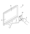
- FIG. 1 is an explanatory diagram schematically illustrating the appearance of the display operation device 1 according to the first embodiment.
- FIG. 1 shows the display operation device 1 as seen from the front.
- the display operation device 1 can operate an image displayed on the display surface 2a of the display unit 2 by a hand movement (so-called gesture) without directly touching the display surface (reference surface) 2a.
- the display unit 2 includes a horizontally long display surface 2 a. Around the display surface 2a, as will be described later, electrodes 3a and 3b used for detecting hand movement are provided.
- the display operation device 1 is supported by a stand ST.
- FIG. 2 is a functional block diagram illustrating a main configuration of the display operation device 1 according to the first embodiment.
- the display operation device 1 includes a display unit 2, a finger position detection unit (position detection unit) 3, a CPU 4, a ROM 5, a RAM 6, a timer 7, a display control unit (display switching unit) 8, a storage unit 9, and the like.
- the CPU (Central Processing Unit) 4 is connected to each part of the hardware via the bus line 10.
- a ROM (Read-Only Memory) 5 stores various control programs, operation parameters, and the like in advance.
- a RAM (Random Access Memory) 6 includes an SRAM (Static RAM), a DRAM (Dynamic RAM), a flash memory, and the like, and temporarily stores various data generated when the CPU 4 executes various programs.
- the CPU 4 constitutes a determination unit, a comparison unit, a standby detection unit, a change amount detection unit, and the like according to the present invention.
- the CPU 4 controls each part of the hardware by loading a control program stored in the ROM 5 in advance on the RAM 6 and executing it, and operates the entire device as the display operation device 1. Further, the CPU 4 receives an input of a processing instruction from the user via the finger position detection unit 3 as will be described later.
- the timer 7 measures various times related to the processing of the CPU 4 and measures time.
- the storage unit 9 is configured by a nonvolatile storage medium such as a flash memory, an EEPROM, or an HDD.
- the storage unit 9 stores in advance various data (position coordinate data (threshold values ⁇ , ⁇ ) of the first virtual plane R1 and second virtual plane R2 and data for a predetermined time such as ⁇ t) described later. .
- the display unit 2 includes a display panel such as a liquid crystal display panel and an organic EL (Electroluminescence) panel. Various information (such as images) is displayed on the display surface 2 a of the display unit 2 in accordance with instructions from the CPU 4.
- a display panel such as a liquid crystal display panel and an organic EL (Electroluminescence) panel.
- Various information (such as images) is displayed on the display surface 2 a of the display unit 2 in accordance with instructions from the CPU 4.
- the finger position detection unit 3 includes a capacitive sensor 30, an integrated circuit such as a programmable system on chip, and the like, and a position coordinate P (X of a user's fingertip positioned in front of the display surface 2a. Coordinate value, Y coordinate value, Z coordinate value) are detected.
- the origin of the coordinate axis is set to the upper left corner of the display surface 2a when viewed from the front, the direction from left to right is the X-axis positive direction, and the direction from top to bottom is the Y-axis positive direction.
- a direction away from the display surface 2a while being orthogonal to the display surface 2a is defined as a positive Z-axis direction.
- the position coordinates P of the detection target such as a fingertip acquired by the position detection unit 3 are stored in the storage unit 9 as appropriate.
- the CPU 4 reads the data of the position coordinates P from the storage unit 9 as necessary, and performs an appropriate calculation using the data.
- the finger position detection unit 3 includes a pair of electrodes 3a and 3b for detecting the position coordinate P of the fingertip, as shown in FIG.
- One electrode 3a is a transmitter electrode (driving side electrode) 3a and has a frame shape (frame shape) surrounding the display area (active area) AA of the display surface 2a.
- a transparent thin film electrode member is used as the transmitter electrode 3a.
- a transparent insulating layer 3c is formed on the transmitter electrode 3a.
- the other electrode 3b is a receiver electrode 3b, and is disposed around the display surface 2a so as to overlap the transmitter electrode 3a through a transparent insulating layer 3c.
- the receiver electrode 3b is divided into four parts, and is arranged so as to be assigned to each side of the rectangular display surface 2a. These electrodes 3a and 3b are set to face the same direction (Z-axis direction) as the display surface 2a.
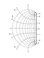
- FIG. 3 is an explanatory diagram schematically showing the electric field distribution formed in front of the display surface 2a.
- a voltage is applied between the electrodes 3a and 3b described above, an electric field having a predetermined distribution is formed in front of the display surface 2a.
- FIG. 3 schematically shows electric lines of force 3d and equipotential lines 3e.
- the spatial region in which the electric field is formed in front of the display surface 2a is a region (detection region F) where a detection target such as a fingertip is detected by the finger position detection unit 3.
- the capacitance sensor 30 including the electrodes 3a and 3b generates a predetermined capacitance between the electrodes 3a and 3b in response to a fingertip entering the region, and an electric signal corresponding to the capacitance. Is output.
- the finger position detection unit 3 detects the electrostatic capacitance generated between the electrodes 3a and 3b based on such an output signal, and further, based on the detection result, the fingertip position coordinates P ( X coordinate value, Y coordinate value, Z coordinate value) can be calculated.
- the detection of the fingertip position coordinates P by the finger position detection unit 3 is repeatedly and regularly executed at regular time intervals.
- a known method is employed as a method for calculating the fingertip position coordinate P from the capacitance generated between the electrodes 3a and 3b.
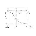
- FIG. 4 is an explanatory diagram schematically showing the signal intensity in the Z-axis direction of the capacitance sensor 30.
- the detection limit signal value (S1) It is about 20 cm (over 20 cm) in the Z-axis direction from 2a.
- a rectangular parallelepiped space region is set as the detection region F.
- two virtual planes having a constant Z coordinate value are set.
- One virtual plane is the first virtual plane R1 set at a position 9 cm away from the display surface 2a in the Z-axis direction, and the other virtual plane is set at a position 20 cm away from the display surface 2a in the Z-axis direction.
- This is the second virtual plane R2.
- the second virtual plane R2 is set at the detection limit position of the Z coordinate value.
- the first virtual plane R1 is set between the display surface 2a and the second virtual plane R2.
- the detection area F is divided into two spatial areas by the first virtual plane R1.
- a space (between the display surface 2a and the first virtual plane R1) on the display surface 2a side from the first virtual plane R1 in the detection region F is particularly referred to as a first detection region F1.
- a space sandwiched between the first virtual plane R1 and the second virtual plane R2 is particularly referred to as a second detection region F2.
- the first detection region F1 is used to recognize a click operation based on the movement of the fingertip in the Z-axis direction.
- the second detection region F2 is for recognizing an input operation based on the movement of the fingertip in the Z-axis direction and an operation based on the movement of the fingertip in the X-axis direction and the Y-axis direction (for example, a flick operation). Used.
- the detection area F is divided into two detection areas F1 and F2 in order of increasing distance from the display surface (reference surface) 2a.
- the CPU 4 recognizes the movement of the user's finger by comparing the position coordinate P of the fingertip detected by the finger position detection unit 3 with various threshold values ( ⁇ and the like) set in advance. The processing content previously associated with is accepted. Further, the CPU 4 controls each target unit (for example, the display control unit 8) in order to execute the received processing content.
- the display control unit 8 displays a predetermined image on the display unit 2 in accordance with an instruction from the CPU 4. For example, the display control unit 8 reads appropriate information from the storage unit 9 based on an instruction from the CPU 4 corresponding to the movement of the user's fingertip (for example, a change in the Z coordinate value of the fingertip), and the read information
- the display image of the display unit 2 is controlled so as to be switched to an image based on.
- the display control unit 8 may be a software function realized by the CPU 4 executing a control program stored in the ROM 5, or may be realized by a dedicated hardware circuit.
- the display operation device 1 according to the present embodiment may include an input unit (push-down input unit) that is not illustrated.
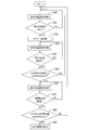
- FIG. 5 is a flowchart showing a procedure of input processing for the display operation device 1 based on a click operation by a fingertip
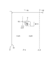
- FIG. 6 is an explanatory diagram schematically showing a single click operation
- FIG. 7 is a double click operation. It is explanatory drawing which represented operation
- the user U first performs a predetermined operation on the display operation device 1 and performs a process of displaying a predetermined reception image (not shown) on the display surface 2a of the display unit 2 before performing an input by a click operation.
- the CPU 4 executes it.
- step S10 the finger position detector 3 acquires the position coordinate P of the fingertip of the user U according to an instruction from the CPU 4.
- the finger position detection unit 3 acquires the position coordinates P (X coordinate value, Y coordinate value, Z coordinate value) of the fingertip.
- the shape of the user U's hand is a state in which only the index finger extends from the fist state toward the display surface 2a. Therefore, the position coordinate of the tip of the index finger is acquired by the finger position detection unit 3.
- the movement of the hand (finger) of the user U who performs an input operation on the display operation device 1 is referred to as “advance” when approaching the display surface 2a, and “reverse” when the user U moves away from the display surface 2a. May be called.
- the CPU 4 determines whether or not the Z coordinate value of the acquired position coordinate P is equal to or less than a predetermined threshold value ⁇ in step S11.
- the threshold value ⁇ is a Z coordinate value of the first virtual plane R1, and indicates a position 9 cm away from the display surface 2a in the Z-axis direction.
- the process proceeds to step S10 again.
- the Z coordinate value of the acquired position coordinate P is equal to or less than the threshold value ⁇ (Z ⁇ ⁇ )
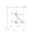
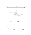
- the process proceeds to step S12. 6 and 7, when the fingertip has entered the first detection area F1 beyond the first virtual plane R1, the Z coordinate value (Z1) at the position coordinate P1 of the fingertip is , ⁇ or less.
- the detection of the fingertip position coordinate P by the finger position detection unit 3 is repeatedly and regularly executed at regular time intervals, and is performed regardless of the presence or absence of the detection target (finger) in the detection region F. . Then, every time the position coordinate P is detected, the process proceeds to step S11, and the detection result (Z coordinate value) by the CPU 4 is compared with the threshold value ⁇ as described above.
- step S12 the CPU 4 starts the timer 7 and measures the time. Thereafter, in step S13, the position coordinate P of the fingertip is detected again as in step S10. After detecting the position coordinates P, the CPU 4 determines whether or not a predetermined time ⁇ t has elapsed since the timer 7 was started. If the CPU 4 determines that the predetermined time ⁇ t has not elapsed, the process proceeds to step S13 again, and the finger position coordinate P is detected again. On the other hand, when the CPU 4 determines that the predetermined time ⁇ t has elapsed, the process proceeds to step S15.
- the finger position detection unit 3 repeats the detection of the fingertip position coordinate P until a predetermined time ⁇ t has elapsed.
- the predetermined time ⁇ t, the detection interval of the position coordinates P, and the like are set so that the detection of the position coordinates P of the fingertip in step S13 is performed a plurality of times (two or more times).
- step S15 the CPU 4 determines whether or not Z ⁇ ⁇ again after the Z coordinate value of the fingertip position coordinate P becomes ⁇ ⁇ Z within a predetermined time ⁇ t. For example, as shown in FIG. 6, if the fingertip has entered the first detection area F1 beyond the first virtual plane R1 for ⁇ t time, Z at the position coordinate P in that case The coordinate value is always ⁇ or less. In such a case, the process proceeds from step S15 to step S16, and the movement of the fingertip of the user U in the detection area F (movement in the Z-axis direction) is recognized as a single click operation and is associated with the movement in advance. Is executed. In the case of the present embodiment, for example, an instruction for switching the received image (not shown) to another image (not shown) is given to the display operation device 1 by such a click operation (single click operation). Entered.
- the first virtual plane R1 is again crossed over the first virtual plane R1.
- the Z coordinate value of the fingertip position coordinate P becomes Z ⁇ ⁇ again after ⁇ ⁇ Z. That is, the Z coordinate value (Z2) at the position coordinate P2 is ⁇ ⁇ Z2, and the Z coordinate value (Z3) at the position coordinate P3 is Z3 ⁇ ⁇ .
- step S15 the process proceeds from step S15 to step S17, and the movement of the fingertip of the user U in the detection area F (movement in the Z-axis direction) is recognized as a double-click operation, and is associated with the process in advance. Is executed.
- an instruction for switching the above-described reception screen (not shown) to another image (not shown) is input to the display operation device 1 by such a click operation (double click operation). Is done.
- the Z coordinate value of the first virtual plane R1 set in the detection region F is the threshold value ⁇ for recognizing the click operation (the motion of the finger of the user U in the Z-axis direction). It is used as. Therefore, the user U can use the first virtual plane R1 as a “click surface” that is a target of click input, and the display unit 2 is moved to the display unit 2 by the movement of the fingertip in the front-rear direction (movement in the Z-axis direction). An input operation can be easily performed on the display operation device 1 without directly touching it. Further, in the display operation device 1 of the present embodiment, the amount of data to be processed by the CPU 4 is smaller than that of a conventional device that recognizes a user's gesture using image data.
- FIG. 8 is a flowchart showing the procedure of the input process for the display operation device 1 based on the forward movement by the fingertip.
- FIG. 9 schematically shows a state in which the fingertip is made to wait in the second detection region F2 before the fingertip is advanced.
- FIG. 10 is an explanatory diagram schematically showing a state in which the fingertip is advanced to the first detection region F1.
- the user U first performs a predetermined operation on the display operation device 1 and displays a predetermined image (not shown) on the display surface 2a of the display unit 2 before performing an input for instructing the display enlargement by the forward movement.
- CPU4 is made to perform the process to perform.
- step S20 the finger position detection unit 3 acquires the position coordinate P of the fingertip of the user U according to an instruction from the CPU 4.
- the CPU 4 determines whether or not the Z coordinate value of the acquired position coordinate P is within a predetermined range ( ⁇ ⁇ Z ⁇ ). judge.
- the threshold value ⁇ is as described above.
- the threshold value ⁇ is the Z coordinate value of the second virtual plane R2, and corresponds to the Z coordinate value at a position 20 cm away from the display surface 2a in the Z-axis direction. Using such threshold values ⁇ and ⁇ , it is determined whether or not the fingertip position coordinate P exists in the second detection region F2.
- the Z coordinate value at the position coordinate P11 of the fingertip satisfies the range of ⁇ ⁇ Z ⁇ . . If the Z coordinate value of the position coordinate P of the fingertip acquired in this way is within the above range, the process proceeds to step S22. On the other hand, if the acquired Z coordinate value of the position coordinate P of the fingertip is outside the above range, the process proceeds to step S20, and the position coordinate P of the finger is detected again.
- the detection of the fingertip position coordinate P by the finger position detection unit 3 is repeatedly performed at regular time intervals, and the presence or absence of the detection target (finger) in the detection region F Done regardless of Then, every time the position coordinate P is detected, the process proceeds to step S21.
- step S22 the CPU 4 starts the timer 7 and measures the time. Thereafter, in step S23, the position coordinate P of the fingertip is detected again as in step S20. After detecting the position coordinate P, the CPU 4 determines whether or not a predetermined time ⁇ t1 (for example, 3 seconds) has elapsed since the timer 7 was started. When the CPU 4 determines that the predetermined time ⁇ t1 has not elapsed, the process proceeds to step S23 again, and the finger position coordinate P is detected again. On the other hand, when the CPU 4 determines that the predetermined time ⁇ t1 has elapsed, the process proceeds to step S25.
- a predetermined time ⁇ t1 for example, 3 seconds
- the finger position detection unit 3 repeats the detection of the fingertip position coordinate P until a predetermined time ⁇ t1 has elapsed.
- the timer 7 is used for measuring the predetermined time ⁇ t1 and is also used for measuring the predetermined time ⁇ t2 described later.
- step S25 the CPU 4 determines that the change amount ⁇ Z1 of the Z coordinate values at the plurality of position coordinates P detected within the predetermined time ⁇ t1 is within a predetermined allowable value D1 (for example, ⁇ 0.5 cm). Determine whether or not.
- the change amount ⁇ Z1 is, for example, the difference between the Z coordinate value (reference value) determined to satisfy the range of ⁇ ⁇ Z ⁇ and the Z coordinate value at the position coordinate P detected within the predetermined time ⁇ t1 in step S21. It is calculated from the difference. If all the change amounts ⁇ Z1 of the Z coordinate values at all the position coordinates P detected after the timer 7 is activated are within the allowable value D1, the process proceeds to step S26.
- step S20 it is determined whether or not the fingertip of the user U is stationary in at least the Z-axis direction within the second detection region F2.
- step S26 the position coordinate P of the fingertip is detected again. This detection is repeated until a predetermined time ⁇ t2 has elapsed since the timer 7 was started, as shown in step S27.
- the predetermined time ⁇ t2 is longer than the predetermined time ⁇ t1 described above. For example, when ⁇ t1 is 3 seconds, ⁇ t2 is set to 3.3 seconds.
- the CPU 4 determines that the predetermined time ⁇ t2 has elapsed, the process proceeds to step 28.
- step S28 the CPU 4 determines whether or not there is at least one Z coordinate value at a plurality of position coordinates P detected within the predetermined time ⁇ t2 that is less than or equal to ⁇ (Z ⁇ ⁇ ). That is, in step S28, it is determined whether or not the fingertip of the user U has moved (moved forward) from the second detection area F2 to the first detection area F1 within ⁇ t2- ⁇ t1 (eg, 0.3 seconds). Is done. For example, as shown in FIG. 10, when the fingertip of the user U waits for a predetermined time ⁇ t1 in the second detection region F2 and moves forward to ⁇ t2 and enters the first detection region F1.
- the Z coordinate value at the position coordinate P12 of the fingertip is ⁇ or less (Z ⁇ ⁇ ).
- the Z coordinate values at a plurality of position coordinates P detected between ⁇ t2 and ⁇ t1 are at least less than ⁇ (Z ⁇ ⁇ ). It may be determined whether there is one.
- step S28 if the CPU 4 determines that there is no Z coordinate value equal to or less than ⁇ (Z ⁇ ⁇ ), the process proceeds to step S20. On the other hand, if the CPU 4 determines in step S28 that there is at least one Z coordinate value equal to or less than ⁇ (Z ⁇ ⁇ ), the process proceeds to step S29.
- step S29 the CPU 4 receives an instruction to switch the image displayed on the display unit 2 to an enlarged image. In this manner, an instruction to switch the image displayed on the display unit 2 to the enlarged image can be input to the display operation device 1 by the forward movement (an example of gesture) by the fingertip of the user U.
- the display control unit 8 reads information on the enlarged image from the storage unit 9 based on an instruction from the CPU 4 and displays the information on the display unit 2 in advance based on the read information.
- An enlarged image is displayed instead of the image that has been displayed.
- an input operation can be easily performed by a forward movement (movement of the fingertip in the Z-axis direction) by the fingertip of the user U without directly touching the display unit 2.
- FIG. 11 is a flowchart showing a procedure of input processing for the display operation device 1 based on the backward movement operation by the fingertip
- FIG. 12 schematically shows a state in which the fingertip is made to wait in the first detection area F1 before the fingertip is moved backward
- FIG. 13 is an explanatory diagram schematically showing a state in which the fingertip is retracted to the second detection region F2.
- the user U performs a predetermined operation on the display operation device 1 and displays a predetermined image (not shown) on the display surface 2a of the display unit 2 before performing an input for instructing the display reduction by the backward movement.
- CPU4 is made to perform the process to perform.
- step S30 the finger position detection unit 3 acquires the position coordinate P of the fingertip of the user U according to an instruction from the CPU 4.
- the CPU 4 determines whether or not the Z coordinate value of the acquired position coordinate P is within a predetermined range (Z ⁇ ⁇ ).
- the threshold value ⁇ is as described above. Using such a threshold value ⁇ , it is determined whether or not the position coordinate P of the fingertip exists in the first detection region F1.
- the Z coordinate value at the position coordinate P21 of the fingertip satisfies the range of Z ⁇ ⁇ . If the Z coordinate value of the position coordinate P of the fingertip acquired in this way is within the above range, the process proceeds to step S32. On the other hand, if the acquired Z coordinate value of the position coordinate P of the fingertip is outside the above range, the process proceeds to step S30, and the position coordinate P of the finger is detected again.
- the detection of the fingertip position coordinate P by the finger position detection unit 3 is repeatedly performed at regular time intervals, and the presence or absence of the detection target (finger) in the detection region F Done regardless of Each time the position coordinate P is detected, the process proceeds to step S31.
- step S32 the CPU 4 starts the timer 7 and measures the time. After that, in step S33, the position coordinate P of the fingertip is detected again as in step S30. After detecting the position coordinate P, the CPU 4 determines whether or not a predetermined time ⁇ t3 (for example, 3 seconds) has elapsed since the timer 7 was started. If the CPU 4 determines that the predetermined time ⁇ t3 has not elapsed, the process proceeds to step S33 again to detect the finger position coordinate P again. On the other hand, when the CPU 4 determines that the predetermined time ⁇ t3 has elapsed, the process proceeds to step S35.
- a predetermined time ⁇ t3 for example, 3 seconds
- the finger position detection unit 3 repeats the detection of the fingertip position coordinate P until a predetermined time ⁇ t3 has elapsed.
- the timer 7 is used for measuring the predetermined time ⁇ t3 and is also used for measuring the predetermined time ⁇ t4 described later.
- step S35 the CPU 4 determines that the change amount ⁇ Z2 of the Z coordinate values at the plurality of position coordinates P detected within the predetermined time ⁇ t3 is within a predetermined allowable value D2 (for example, ⁇ 0.5 cm). Determine whether or not.
- the change amount ⁇ Z2 is obtained from the difference between the Z coordinate value (reference value) determined to satisfy the range of Z ⁇ ⁇ in step S31 and the Z coordinate value at the position coordinate P detected within the predetermined time ⁇ t13. Desired. If all the change amounts ⁇ Z2 of the Z coordinate values at all the position coordinates P detected after the timer 7 is started are within the allowable value D2, the process proceeds to step S36.
- step S30 it is determined whether or not the fingertip of the user U is stationary in at least the Z-axis direction within the first detection area F1.
- step S36 the position coordinate P of the fingertip is detected again. This detection is repeated until a predetermined time ⁇ t4 after the timer 7 is started, as shown in step S37.
- the predetermined time ⁇ t4 is longer than the predetermined time ⁇ t3 described above. For example, when ⁇ t3 is 3 seconds, ⁇ t4 is set to 3.3 seconds.
- the CPU 4 determines that the predetermined time ⁇ t4 has elapsed, the process proceeds to step 38.
- step S38 the CPU 4 determines in advance a difference ⁇ Z3 between the Z coordinate values of the plurality of position coordinates P detected within the predetermined time ⁇ t4 and the Z coordinate value (that is, ⁇ ) of the first virtual plane R1. It is determined whether or not there is at least one case that is equal to or greater than a predetermined value D3 (for example, 3 cm). That is, in step S38, it is determined whether or not the fingertip of the user U has moved (moved forward) from the first detection area F1 to the second detection area F2 within ⁇ t4- ⁇ t3 (eg, 0.3 seconds). Is done.
- a predetermined value D3 for example, 3 cm
- the difference ⁇ Z3 between the Z coordinate values at a plurality of position coordinates P detected between ⁇ t4 and ⁇ t3 (for example, 0.3 seconds) and ⁇ is a predetermined value. It may be determined whether or not there is at least one case of D3 or more.
- the fingertip of the user U waits for a predetermined time ⁇ t3 in the first detection area F1, and then, as shown in FIG. Retreat from the plane R1 to a position (position coordinate P22) that is separated by a predetermined value D3 or more along the Z-axis direction. If the CPU 4 determines in step S38 that the difference ⁇ Z3 is not greater than or equal to the predetermined value D3, the process proceeds to step S30. On the other hand, when the CPU 4 determines that there is at least one case where the difference ⁇ Z3 is equal to or greater than the predetermined value D3 in step S38, the process proceeds to step S39.
- step S39 the CPU 4 receives an instruction (input) to switch the image displayed on the display unit 2 to a reduced image.
- an instruction to switch the image displayed on the display unit 2 to a reduced image can be input to the display operation device 1 by the backward movement (an example of gesture) by the fingertip of the user U.
- the display control unit 8 reads information on the reduced image from the storage unit 9 based on an instruction from the CPU 4 and displays the information on the display unit 2 based on the read information.
- a reduced image is displayed instead of the image that has been displayed.
- the display operation device 1 it is possible to easily perform an input operation by a retreating operation (movement of the fingertip in the Z-axis direction) by the fingertip of the user U without directly touching the display unit 2.
- FIG. 14 is an explanatory diagram schematically illustrating the appearance of the display operation device 1A according to the second embodiment
- FIG. 15 is a functional block diagram illustrating the main configuration of the display operation device 1A according to the second embodiment.
- the display operation device 1A according to the present embodiment includes the 3D image display unit 2A instead of the display unit 2 in the display operation device 1 according to the above-described first embodiment, and also performs 3D image display control instead of the display control unit 8. 8A is provided.
- the display operation device 1 ⁇ / b> A according to the present embodiment information corresponding to the three-dimensional image is stored in the storage unit 9. Since other configurations are the same as those of the first embodiment, the same reference numerals are given to the same configurations, and descriptions thereof are omitted.
- the display operation device 1A displays a 3D image 100 in front of the 3D image display unit 2A.
- the three-dimensional image display unit 2A displays the three-dimensional image 100 by a parallax barrier method (parallax barrier method), and includes a liquid crystal display panel, a parallax barrier, and the like.
- the three-dimensional image 100 is visually recognized by the user U as if it floats up from the display surface 2Aa of the three-dimensional image display unit 2Aa.
- the three-dimensional image display control unit 8A displays a predetermined three-dimensional image 100 on the three-dimensional image display unit 2A in response to an instruction from the CPU 4.
- the 3D image display control unit 8A may be a software function realized by the CPU 4 executing a control program stored in the ROM 5, or may be realized by a dedicated hardware circuit.
- the display operation device 1A of the present embodiment also includes the finger position detection unit 3 similar to the display operation device 1 described above. As shown in FIG. 16, the display operation device 1A is in front of the display operation device 1A. A similar detection region F is formed.
- FIG. 17 is a flowchart showing the procedure of the input process for the display operation device 1A based on the click operation by the fingertip.
- step S40 the user U performs a predetermined operation on the display operation device 1A, and the CPU 4 performs a process in which the 3D image display unit 2A displays the predetermined 3D image 100 on the first virtual plane R1. Let it run.
- step S41 the CPU 4 determines whether or not there is a click input.
- the processing content in step S41 is the same as the processing content of the click operation of the first embodiment (steps S10 to S16 in the flowchart of FIG. 5).
- the user U performs a click input using the first virtual plane R ⁇ b> 1 with the feeling of directly touching the three-dimensional image 100.
- step S41 when the CPU 4 determines that an input by a click operation (single click operation) has been received, the process proceeds to step S42, and a new three-dimensional image (not shown) previously associated with the click input is converted into a third order.
- the original image display unit 2A displays it.
- the three-dimensional image 100 on the back surface of the playing card shown in FIG. 14 may be switched to a three-dimensional image on the playing card surface by clicking input.
- the 3D image 100 displayed by the 3D image display unit 2A is arranged so as to overlap the first virtual plane R1 (click surface).
- An input operation for switching to another three-dimensional image can be performed as if the image 100 is touched directly with a fingertip.
- the user U cannot easily recognize the operation target (the click surface formed of the first virtual plane R1), but the display operation device 1A of the present embodiment has such a problem. It will be resolved.
- the display unit may have a touch panel function. That is, the non-contact type input unit as described above and the contact type input unit may be used in combination.
- the arrangement of the electrodes (transmitter electrode, receiver electrode) provided in the electrostatic capacity sensor may be such that a predetermined detection region as exemplified in the above embodiment can be formed in front of the display unit (user side).
- a predetermined detection region as exemplified in the above embodiment can be formed in front of the display unit (user side).
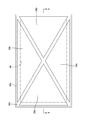
- FIG. 18 is a front view schematically showing Modification 1 of the electrodes 3Aa and 3Ab included in the capacitance sensor
- FIG. 19 is a cross-sectional view taken along line AA of FIG.
- one electrode (transmitter electrode) 3Aa is arranged so as to overlap the display area (active area) AA of the display unit 2
- the other electrode (receiver electrode) 3Ab has a transparent insulating layer 3Ac.
- the electrode 3Ab is divided into four parts, each of which has a triangular shape.
- the electrodes 3Aa and 3Ab may be arranged so as to overlap the display area AA.
- a transparent conductive film is used as an electrode material constituting the electrodes 3Aa and 3Ab.
- FIG. 20 is a front view schematically showing Modification 2 of the electrodes 3Ba and 3Bb included in the capacitance sensor
- FIG. 21 is a cross-sectional view taken along the line BB of FIG.
- one electrode (transmitter electrode) 3Ba has a frame shape (frame shape) surrounding the display area (active area) AA of the display unit 2. That is, the electrode 3Ba is disposed in the non-display area (frame region).
- a frame-shaped insulating layer 3Bc is formed on the electrode 3Ba.
- the other electrode (receiver electrode) 3Bb is disposed so as to overlap the electrode 3Ba via the insulating layer 3Bc.
- the electrode 3Bb has a frame shape as a whole, but is divided into four parts so as to be assigned to each side of the rectangular display area AA. As in Modification 2, the electrodes 3Ba and 3Bb may be arranged only in the non-display area (frame area) surrounding the display area AA.
- the finger position detection unit has received an input operation by detecting the position coordinates of the user's hand (fingertip), but the present invention is not limited to this, In other embodiments, for example, a detection object such as a pen type may be a detection target of the finger position detection unit.
- the second virtual plane is set to the position of the detection limit of the signal intensity in the Z-axis direction.
- the position of the second virtual plane is set to the detection limit. May also be set at a position closer to the display / operation device side.
- the first virtual plane is not particularly limited as long as it is set between the display surface (reference surface) of the display unit and the detection limit position in the Z-axis direction.
- the first virtual plane is set closer to the display surface side (display operation device side) than the intermediate position between the display surface and the detection limit position for the purpose of securing a large second detection area in the Z-axis direction. It is preferable to do.
- the position of the first virtual plane closer to the display surface side the user can easily put his / her fingertips in and out of the first detection area, and the first virtual plane (click plane) It becomes easy to perform an input operation (click operation).
- the display image is switched to the enlarged image by the input operation based on the forward movement by the fingertip, and the display image is switched to the reduced image by the input operation based on the backward movement.
- the display image may be switched to a reduced image by an input operation based on a forward movement, and the display image may be switched to an enlarged image by an input operation based on a backward movement.
- the display operation device may be instructed to perform processing other than enlargement / reduction of the display image by the forward operation and the backward operation by the fingertip.
- the display image is switched by an input operation based on the operation of the fingertip.
- processing in other configurations for example, a speaker
- the movement of the fingertip in the Z-axis direction is recognized using only the Z coordinate value of the obtained fingertip position coordinates P. In other embodiments, however, it is necessary. Accordingly, the movement of the fingertip may be recognized using not only the Z coordinate value but also the X coordinate value and the Y coordinate value. In addition, it is preferable to use a capacitance sensor as a sensor of the finger position detection unit because the movement of the fingertip that is the detection target in the Z-axis direction can be easily grasped.
- the three-dimensional image is switched to another three-dimensional image (still image) in accordance with the operation of the user's fingertip (clicking operation).
- the display operation device may be configured such that a three-dimensional image (for example, the earth) performs an operation such as rotation after receiving the operation (clicking operation) of the fingertip of the user.
- a switch image may be displayed as a three-dimensional image so that the user can recognize the image as a virtual switch.
- SYMBOLS 1 Display operation apparatus (input device), 2 ... Display part, 2a ... Display surface (reference surface), 3 ... Finger position detection part (position detection part), 3a, 3b ... Electrode, 30 ... sensor, 4 ... CPU (determination unit, comparison unit, standby detection unit, change amount detection unit), 5 ... ROM, 6 ... RAM, 7 ... timer, 8. .. display control unit (display switching unit), 9 ... storage unit, 10 ... bus line, F ... detection area, R1 ... first virtual plane (virtual plane), R2 ... first 2 virtual planes, U ... user, P ... position coordinates of detection target
Landscapes
- Engineering & Computer Science (AREA)
- General Engineering & Computer Science (AREA)
- Theoretical Computer Science (AREA)
- Human Computer Interaction (AREA)
- Physics & Mathematics (AREA)
- General Physics & Mathematics (AREA)
- Position Input By Displaying (AREA)
Abstract
本発明の入力装置1は、基準面2aと、基準面2aの前方の空間領域に検出領域Fを形成しつつ、検出領域内に進入した指等の検出対象Uの検出領域F内における位置座標Pを検出する位置検出部3と、検出領域Fを前後方向で仕切るように設定された仮想平面R1の前後方向における位置座標(閾値α)と、位置検出部3により検出された検出対象Uの前後方向における位置座標(Z座標値)とを比較する比較部と、比較部の比較結果に基づいて、検出対象Uの入力動作を判断する判断部とを備える。
Description
本発明は、入力装置に関する。
特許文献1に示されるように、利用者が表示パネルの前方にある空間領域で手を動かすことにより、表示画像を切り替える等の入力操作を行う非接触型の入力装置が知られている。前記装置では、利用者の手の動き(つまり、ジェスチャー)をカメラで撮影し、その撮像データを利用してジェスチャーを認識している。
(発明が解決しようとする課題)
カメラを利用したジェスチャー認識では、表示パネルの表示面に対して平行に移動する手の動きは認識し易いものの、表示面に対して垂直に移動する手の動き(つまり、表示面に対する前後方向の動き)は、移動距離を測定し難い等の理由により、認識することが難しい。
カメラを利用したジェスチャー認識では、表示パネルの表示面に対して平行に移動する手の動きは認識し易いものの、表示面に対して垂直に移動する手の動き(つまり、表示面に対する前後方向の動き)は、移動距離を測定し難い等の理由により、認識することが難しい。
本発明の目的は、入力操作性に優れる非接触型の入力装置を提供することである。
(課題を解決するための手段)
本発明に係る入力装置は、基準面と、前記基準面の前方の空間領域に検出領域を形成しつつ、前記検出領域内に進入した指等の検出対象の前記検出領域内における位置座標を検出する位置検出部と、前記検出領域を前後方向で仕切るように設定された仮想平面の前後方向における位置座標と、前記位置検出部により検出された前記検出対象の前後方向における位置座標とを比較する比較部と、前記比較部の比較結果に基づいて、前記検出対象の入力動作を判断する判断部とを備える。
本発明に係る入力装置は、基準面と、前記基準面の前方の空間領域に検出領域を形成しつつ、前記検出領域内に進入した指等の検出対象の前記検出領域内における位置座標を検出する位置検出部と、前記検出領域を前後方向で仕切るように設定された仮想平面の前後方向における位置座標と、前記位置検出部により検出された前記検出対象の前後方向における位置座標とを比較する比較部と、前記比較部の比較結果に基づいて、前記検出対象の入力動作を判断する判断部とを備える。
前記入力装置は、前記検出領域を前後方向で仕切るように設定された仮想平面の前後方向における位置座標と、前記位置検出部により検出された前記検出対象の前後方向における位置座標とを比較することで、前記検出対象の入力動作を判断することが可能である。つまり、前記入力装置は、前記検出対象の前後方向における入力動作を判断することが可能であり、入力操作性に優れる。
前記入力装置において、前記判断部は、前記比較部の比較結果が、前記検出対象の前記位置座標が前記仮想平面の前記位置座標以下である場合、前記入力動作を、前記仮想平面を前記基準面に近付く向きに通過するクリック動作として判断するものであってもよい。
また、本発明に係る入力装置は、基準面と、前記基準面の前方の空間領域に検出領域を形成しつつ、前記検出領域内に進入した指等の検出対象の前記検出領域内における位置座標を検出する位置検出部と、前記検出領域が第1検出領域及び第2検出領域に分かれるように前記検出領域を前後方向に仕切る仮想平面と、前記位置検出部の検出結果に基づいて、前記検出対象が前記第2検出領域で所定時間待機することを検出する待機検出部と、前記位置検出部の検出結果に基づいて、前記所定時間の待機後に前記第2検出領域から前記第1検出領域に向かって移動する前記検出対象の変化量を検出する変化量検出部と、前記変化量検出部の検出結果に基づいて、前記検出対象の入力動作を判断する判断部とを備える。
前記入力装置では、検出領域が仮想平面によって、前後方向に第1検出領域及び第2検出領域に分けられており、これらの2つの検出領域を利用することによって、前記検出対象の前後方向における入力動作を判断することが可能であり、入力操作性に優れる。
また、本発明に係る入力装置は、基準面と、前記基準面の前方の空間領域に検出領域を形成しつつ、前記検出領域内に進入した指等の検出対象の前記検出領域内における位置座標を検出する位置検出部と、前記検出領域が第1検出領域及び第2検出領域に分かれるように前記検出領域を前後方向に仕切る仮想平面と、前記位置検出部の検出結果に基づいて、前記検出対象が前記第1検出領域で所定時間待機することを検出する待機検出部と、前記位置検出部の検出結果に基づいて、前記所定時間の待機後に前記第1検出領域から前記第2検出領域に向かって移動する前記検出対象の変化量を検出する変化量検出部と、前記変化量検出部の検出結果に基づいて、前記検出対象の入力動作を判断する判断部とを備える。
前記入力装置では、検出領域が仮想平面によって、前後方向に第1検出領域及び第2検出領域に分けられており、これらの2つの検出領域を利用することによって、前記検出対象の前後方向における入力動作を判断することが可能であり、入力操作性に優れる。
前記入力装置において、前記基準面は、画像を表示する表示部の表示面からなるものであってもよい。
前記入力装置において、前記表示部の表示面に表示する画像を、前記判断部の判断結果に基づいて前記入力動作に対応付けられた他の画像に切り替える表示切替部を備えるものであってもよい。
また、本発明に係る入力装置は、表示面から浮き上がるように三次元画像を表示する表示部と、前記表示面の前方の空間領域に検出領域を形成しつつ、前記検出領域内に進入した指等の検出対象の前記検出領域内における位置座標を検出する位置検出部と、前記検出領域を前後方向で仕切ると共に、前記表示面から浮き上がった前記三次元画像の位置と重なるように設定された仮想平面の前後方向における位置座標と、前記位置検出部により取得された前記検出対象の前後方向における位置座標とを比較する比較部と、前記比較部の比較結果に基づいて、前記検出対象の入力動作を判断する判断部とを備える。
前記入力装置では、検出領域を前後方向で仕切る仮想平面の位置が、表示部の表示面から浮き上がった三次元画像の位置と重なるように設定されており、利用者は指等の前後方向における入力動作により、三次元画像に直接、触れる感覚で入力操作を行うことが可能である。
前記入力装置において、前記判断部は、前記比較部の比較結果が、前記検出対象の前記位置座標が前記仮想平面の前記位置座標以下である場合、前記入力動作を、前記仮想平面を前記基準面に近付く向きに通過するクリック動作として判断するものであってもよい。
前記入力装置において、前記表示部が前記表示面から浮き上がるように表示する三次元画像を、前記判断部の判断結果に基づいて前記入力動作に対応付けられた他の三次元画像に切り替える表示切替部を備えるものであってもよい。このように三次元画像が他の三次元画像に切り替えられると、利用者は直接、元の三次元画像に触れたことによって、他の三次元画像に切り替わったように感じることができる。
前記入力装置において、前記位置検出部は、前記検出領域を電界によって形成するための一対の電極を含むセンサを有し、前記電極間の静電容量に基づいて前記検出対象の位置座標を取得するものが好ましい。つまり、静電容量方式のセンサ等によって構成された位置検出部は、一般的に他の方式と比べて、基準面(又は表示面)に対する前後方向の検出精度が優れる。そのため、このような静電容量センサを含む位置検出部を利用することが好ましい。
(発明の効果)
本発明によれば、入力操作性に優れる非接触型の入力装置を提供することができる。
本発明によれば、入力操作性に優れる非接触型の入力装置を提供することができる。
<実施形態1>
以下、本発明の実施形態1を、図1乃至図13を参照しつつ説明する。本実施形態では、入力装置の一例として、表示操作装置1を例示する。図1は、実施形態1の表示操作装置1の外観を模式的に表した説明図である。図1には、正面から見た状態の表示操作装置1が示されている。表示操作装置1は、表示部2の表示面2aに表示される画像を、利用者が表示面(基準面)2aに直接、触れることなく、手の動作(所謂、ジェスチャー)によって操作することが可能な装置である。表示部2は、図1に示されるように横長の矩形状の表示面2aを備えている。表示面2aの周囲には、後述するように、手の動作を検出するために利用される電極3a,3bが設けられている。表示操作装置1は、スタンドSTによって支えられている。
以下、本発明の実施形態1を、図1乃至図13を参照しつつ説明する。本実施形態では、入力装置の一例として、表示操作装置1を例示する。図1は、実施形態1の表示操作装置1の外観を模式的に表した説明図である。図1には、正面から見た状態の表示操作装置1が示されている。表示操作装置1は、表示部2の表示面2aに表示される画像を、利用者が表示面(基準面)2aに直接、触れることなく、手の動作(所謂、ジェスチャー)によって操作することが可能な装置である。表示部2は、図1に示されるように横長の矩形状の表示面2aを備えている。表示面2aの周囲には、後述するように、手の動作を検出するために利用される電極3a,3bが設けられている。表示操作装置1は、スタンドSTによって支えられている。
図2は、実施形態1の表示操作装置1の要部構成を示す機能ブロック図である。表示操作装置1は、表示部2、指位置検出部(位置検出部)3、CPU4、ROM5、RAM6、タイマー7、表示制御部(表示切替部)8、記憶部9等を備えている。
CPU(Central Processing Unit)4は、バスライン10を介してハードウェア各部に接続されている。ROM(Read-Only Memory)5には各種の制御プログラム、演算用のパラメータ等が予め格納されている。RAM(Random Access Memory)6は、SRAM(Static RAM)、DRAM(Dynamic RAM)、フラッシュメモリ等からなり、CPU4による各種プログラムの実行時に発生する種々のデータを一時的に記憶する。なお、CPU4は、本発明の判断部、比較部、待機検出部、変化量検出部等を構成する。
CPU4は、ROM5に予め格納されている制御プログラムをRAM6上にロードして実行することによりハードウェア各部を制御し、装置全体を表示操作装置1として動作させる。また、CPU4は、後述するように指位置検出部3を介して、利用者から処理の指示の入力を受け付ける。タイマー7は、CPU4の処理に係る各種の時間の計測や時刻をする。記憶部9は、フラッシュメモリ、EEPROM、HDD等の不揮発性の記憶媒体により構成されている。なお、記憶部9には、後述する各種データ(第1仮想平面R1,第2仮想平面R2の位置座標データ(閾値α、β)や、Δt等の所定時間のデータ)が予め記憶されている。
表示部2は、液晶表示パネル、有機EL(Electro luminescence)パネル等の表示パネル等から構成される。表示部2の表示面2aには、CPU4からの指示に従い各種情報(画像等)が表示される。
指位置検出部3は、静電容量方式のセンサ30や、プログラマブル・システム・オン・チップ等の集積回路等から構成され、表示面2aの前方に位置する利用者の指先の位置座標P(X座標値、Y座標値、Z座標値)を検出する。なお、本実施形態では、座標軸の原点を表示面2aの正面視左上角に設定し、左から右へ向かう方向をX軸正方向とし、上から下へ向かう方向をY軸正方向とする。また、表示面2aに直交しつつ表示面2aから離れる方向を、Z軸正方向とする。位置検出部3により取得された指先等の検出対象の位置座標Pは、適宜、記憶部9に記憶される。なお、CPU4は、必要に応じて記憶部9から位置座標Pのデータを読み出し、そのデータを用いて適宜、演算を行う。
指位置検出部3は、図1に示されるように、指先の位置座標Pを検出するための一対の電極3a,3bを備えている。一方の電極3aは、トランスミッタ電極(駆動側電極)3aであり、表示面2aの表示エリア(アクティブエリア)AAの回りを囲むような枠状(額縁状)をなしている。トランスミッタ電極3aとしては、透明な薄膜状の電極部材が利用される。なお、トランスミッタ電極3a上には、透明な絶縁層3cが形成されている。他方の電極3bは、レシーバ電極3bであり、透明な絶縁層3cを介してトランスミッタ電極3aと重なるように、表示面2aの周囲に配置されている。本実施形態の場合、レシーバ電極3bは4個に分けられており、矩形状をなす表示面2aの各辺に割り当てられるように配置されている。これらの電極3a,3bは、表示面2aと同じ方向(Z軸方向)を向くように設定されている。
図3は、表示面2aの前方に形成される電界分布を模式的に表した説明図である。上述した電極3a,3b間に電圧が印加されると、表示面2aの前方に、所定の分布を有する電界が形成される。図3には、電気力線3d及び等電位線3eが模式的に示されている。このように表示面2aの前方に電界が形成された空間領域が、指位置検出部3によって指先等の検出対象が検出される領域(検出領域F)となっている。この領域内に、検出対象である指先等が進入すると、電極3a,3b間の静電容量が変動する。前記電極3a,3bを備える静電容量センサ30は、前記領域に指先が進入するのに応じて前記電極3a,3b間に所定の静電容量を生じさせ、その静電容量に応じた電気信号を出力する。指位置検出部3は、このような出力信号に基づいて、前記電極3a,3b間に生じた静電容量を検出し、更にこの検出結果に基づいて、検出領域内における指先の位置座標P(X座標値、Y座標値、Z座標値)を算出することができる。なお、指位置検出部3による指先の位置座標Pの検出は、一定の時間間隔で繰り返し定常的に実行される。なお、前記電極3a,3b間に生じた静電容量から、指先の位置座標Pを算出する方法としては、公知の手法が採用される。
図4は、静電容量センサ30のZ軸方向のシグナル強度を模式的に表した説明図である。本実施形態の場合、表示面2aの大きさが対角7型であり、静電容量センサ30の駆動電圧を3.3Vが設定された場合、検出限界のシグナル値(S1)は、表示面2aからZ軸方向に約20cm(20cm強)のところとなる。本実施形態の場合、表示面2aの〔横方向(X軸方向)の長さ〕×〔表示面2aの縦方向(Y軸方向)の長さ〕×〔Z軸方向の長さ(20cm)〕からなる直方体状の空間領域が、検出領域Fとして設定されている。
また、検出領域Fには、Z座標値が一定である2つの仮想平面が設定されている。一方の仮想平面は、表示面2aからZ軸方向に9cm離れた位置に設定される第1仮想平面R1であり、他方の仮想平面は、表示面2aからZ軸方向に20cm離れた位置に設定される第2仮想平面R2である。本実施形態の場合、第2仮想平面R2は、Z座標値の検出限界位置に設定されている。第1仮想平面R1は、表示面2aと第2仮想平面R2との間に設定される。
第1仮想平面R1により、検出領域Fは、2つの空間領域に分けられている。本明細書において、検出領域Fのうち、第1仮想平面R1から表示面2a側にある空間(表示面2aと第1仮想平面R1との間)を、特に第1検出領域F1と称する。これに対し、第1仮想平面R1と第2仮想平面R2とで挟まれた空間を、特に第2検出領域F2と称する。第1検出領域F1は、例えば、後述するように、指先のZ軸方向の動きに基づいたクリック動作を認識するために利用される。これに対し、第2検出領域F2は、指先のZ軸方向の動きに基づく入力動作や、指先のX軸方向及びY軸方向の動きに基づいた動作(例えば、フリック動作)を認識するために利用される。このように、検出領域Fは、表示面(基準面)2aから近い順に2つの検出領域F1,F2に分けて用いられる。
CPU4は、指位置検出部3により検出された指先の位置座標Pと、予め設定されている各種の閾値(α等)とを比較することにより、利用者の指の動きを認識し、その動きに対して予め対応付けられている処理内容を受け付ける。そして、更にCPU4は、受け付けた処理内容を実行するために、目的となる各部(例えば、表示制御部8)を制御する。
表示制御部8は、CPU4からの指示に応じて表示部2に所定の画像を表示させる。表示制御部8は、例えば、利用者の指先の動き(例えば、指先のZ座標値の変化)に対応したCPU4からの指示に基づいて、適切な情報を記憶部9から読み出し、その読み出した情報に基づく画像に切り替わるように表示部2の表示画像を制御する。なお、表示制御部8は、ROM5に記憶されている制御プログラムをCPU4が実行することによって実現されるソフトウェア機能であってもよいし、専用のハードウェア回路によって実現されてもよい。なお、本実施形態の表示操作装置1は、図示されない入力部(押下式入力部)等を備えてもよい。
以下、本実施形態の表示操作装置1において行われる、利用者Uの指先の動作(Z軸方向の動き)に基づいた入力処理の手順を説明する。なお、以下に示される内容は、利用者Uの指先の動作(Z軸方向の動き)に基づいた入力処理の一例であり、本発明の内容はこれらの内容に限られない。ここで、先ず、2種類のクリック動作(シングルクリック動作、及びダブルクリック動作)に基づいた入力処理の手順について説明する。
(クリック動作による入力操作)
図5は、指先によるクリック動作に基づいた表示操作装置1に対する入力処理の手順を示すフローチャートであり、図6は、シングルクリック動作を模式的に表した説明図であり、図7は、ダブルクリック動作を模式的に表した説明図である。利用者Uは、先ず、クリック動作による入力を行う前に、表示操作装置1に対して所定の操作を行い、表示部2の表示面2aに所定の受付画像(不図示)を表示する処理をCPU4に実行させる。
図5は、指先によるクリック動作に基づいた表示操作装置1に対する入力処理の手順を示すフローチャートであり、図6は、シングルクリック動作を模式的に表した説明図であり、図7は、ダブルクリック動作を模式的に表した説明図である。利用者Uは、先ず、クリック動作による入力を行う前に、表示操作装置1に対して所定の操作を行い、表示部2の表示面2aに所定の受付画像(不図示)を表示する処理をCPU4に実行させる。
ステップS10において、CPU4からの指示により、指位置検出部3が、利用者Uの指先の位置座標Pを取得する。検出領域F内に指が進入すると、ステップS10において、指位置検出部3により、指先の位置座標P(X座標値、Y座標値、Z座標値)が取得される。本実施形態の場合、利用者Uの手の形は、図6及び図7に示されるように、握りこぶしの状態から人差し指のみが表示面2aに向かって延びた状態となっている。そのため、人差し指の先端の位置座標が、指位置検出部3により取得されることになる。なお、表示操作装置1に対して入力操作を行う利用者Uの手(指)の動きについて、表示面2aに近付く場合を「前進」と称し、反対に表示面2aから遠ざかる場合を「後退」と称する場合がある。
指先の位置座標Pが取得された後、CPU4が、ステップS11において、取得された位置座標PのZ座標値が、予め定められている閾値α以下であるか否かを判定する。閾値αは、第1仮想平面R1のZ座標値のことであり、表示面2aからZ軸方向に9cm離れた位置を示す。取得された位置座標PのZ座標値が、閾値αよりも大きい場合(Z>α)、再びステップS10へ移行する。これに対し、取得された位置座標PのZ座標値が、閾値α以下の場合(Z≦α)、ステップS12へ移行する。なお、図6及び図7に示されるように、指先が第1仮想平面R1を越えて第1検出領域F1内に進入している場合、その指先の位置座標P1におけるZ座標値(Z1)は、α以下となっている。
なお、指位置検出部3による指先の位置座標Pの検出は、一定の時間間隔で繰り返し定常的に実行されるものであり、検出領域F内の検出対象(指)の有無に関係なく行われる。そして、位置座標Pの検出が行われる度に、ステップS11へ移行し、上述のようにCPU4による検出結果(Z座標値)と閾値αとの比較が行われる。
ステップS12において、CPU4は、タイマー7を起動させて時間を計測する。その後、ステップS13において、再びステップS10と同様、指先の位置座標Pを検出する。位置座標Pの検出後、CPU4は、タイマー7が起動してから予め定められている所定時間Δtを経過したか否かを判断する。CPU4が所定時間Δtを経過していないと判断した場合は、再びステップS13へ移行し、再び指の位置座標Pの検出を行う。これに対し、CPU4が所定時間Δtを経過したと判断した場合、ステップS15へ移行する。つまり、指先が第1検出領域F1内に進入してタイマー7が起動した後、所定時間Δtを経過するまで、指位置検出部3は、指先の位置座標Pの検出を繰り返すことになる。本実施形態の場合、ステップS13における指先の位置座標Pの検出は、複数回(2回以上)行われるように、所定時間Δtや位置座標Pの検出間隔等が設定されている。
ステップS15において、CPU4は、所定時間Δt内に、指先の位置座標PのZ座標値が、α<Zとなった後、再びZ≦αとなったか否かを判断する。例えば、図6に示されるように、指先が第1仮想平面R1を越えて第1検出領域F1内に、Δt時間の間、進入し状態となっていると、その場合の位置座標PにおけるZ座標値は、常にα以下となる。このような場合、ステップS15からステップS16へ移行し、検出領域F内における利用者Uの指先の動き(Z軸方向の動き)は、シングルクリック動作と認識され、それに予め対応付けられている処理が実行される。本実施形態の場合、このようなクリック動作(シングルクリック動作)により、例えば、上述の受付画像(不図示)が、他の画像(不図示)に切り替わるような指示が表示操作装置1に対して入力される。
これに対し、例えば、所定時間Δt内において、図7に示されるように、指先が一旦、第2検出領域F2側に後退した後(位置座標P2)、再び第1仮想平面R1を越えて第1検出領域F1内に進入した場合(位置座標P3)、指先の位置座標PのZ座標値は、α<Zとなった後、再びZ≦αとなる。つまり、位置座標P2におけるZ座標値(Z2)は、α<Z2となっており、位置座標P3におけるZ座標値(Z3)は、Z3≦αとなっている。このような場合、ステップS15からステップS17へ移行し、検出領域F内における利用者Uの指先の動き(Z軸方向の動き)は、ダブルクリック動作と認識され、それに予め対応付けられている処理が実行される。本実施形態の場合、このようなクリック動作(ダブルクリック動作)により、例えば、上述の受付画面(不図示)が他の画像(不図示)に切り替わるような指示が表示操作装置1に対して入力される。
このように表示操作装置1では、検出領域F内に設定された第1仮想平面R1のZ座標値が、クリック動作(利用者UのZ軸方向の指の動作)を認識するための閾値αとして利用されている。そのため、利用者Uは、第1仮想平面R1を、クリック入力の対象となる「クリック面」として利用することができ、指先の前後方向の動き(Z軸方向の動き)によって、表示部2に直接、触れることなく、表示操作装置1に対して容易に入力操作を行うことができる。また、本実施形態の表示操作装置1では、撮像データを利用して利用者のジェスチャーを認識する従来の装置と比べて、CPU4が処理すべきデータ量が少なくなる。
(前進動作による入力操作)
次いで、利用者Uの指先による前進動作に基づいた入力処理の手順について説明する。本実施形態では、指先による前進動作によって、表示部2に表示される画像が拡大画像に切り替わるような指示が表示操作装置1に対して入力される。図8は、指先による前進動作に基づいた表示操作装置1に対する入力処理の手順を示すフローチャートであり、図9は、指先を前進させる前に、第2検出領域F2内で待機させた状態を模式的に表した説明図であり、図10は、指先を第1検出領域F1まで前進させた状態を模式的に表した説明図である。
次いで、利用者Uの指先による前進動作に基づいた入力処理の手順について説明する。本実施形態では、指先による前進動作によって、表示部2に表示される画像が拡大画像に切り替わるような指示が表示操作装置1に対して入力される。図8は、指先による前進動作に基づいた表示操作装置1に対する入力処理の手順を示すフローチャートであり、図9は、指先を前進させる前に、第2検出領域F2内で待機させた状態を模式的に表した説明図であり、図10は、指先を第1検出領域F1まで前進させた状態を模式的に表した説明図である。
利用者Uは、先ず前進動作による表示拡大を指示する入力を行う前に、表示操作装置1に対して所定の操作を行い、表示部2の表示面2aに所定の画像(不図示)を表示する処理をCPU4に実行させる。
次いで、ステップS20において、CPU4からの指示により、指位置検出部3が、利用者Uの指先の位置座標Pを取得する。指先の位置座標Pが取得された後、ステップ21において、CPU4が、取得された位置座標PのZ座標値が、予め定められている範囲(α<Z<β)内にあるか否かを判定する。閾値αは上述のとおりである。閾値βは、第2仮想平面R2のZ座標値のことであり、表示面2aからZ軸方向に20cm離れた位置のZ座標値に相当する。このような閾値α,βを利用して、指先の位置座標Pが第2検出領域F2内に存在するか否かが判断される。
例えば、図9に示されるように、利用者Uの指先が第2検出領域F2内にある場合、その指先の位置座標P11におけるZ座標値は、α<Z<βの範囲を満たすことになる。このように取得された指先の位置座標PのZ座標値が、上記範囲内であれば、ステップS22へ移行する。これに対し、取得された指先の位置座標PのZ座標値が、上記範囲外であれば、ステップS20へ移行し、再び指の位置座標Pの検出を行う。
なお、指位置検出部3による指先の位置座標Pの検出は、上述したように、一定の時間間隔で繰り返し定常的に実行されるものであり、検出領域F内の検出対象(指)の有無に関係なく行われる。そして、位置座標Pの検出が行われる度に、ステップS21へ移行することになる。
ステップS22において、CPU4は、タイマー7を起動させて時間を計測する。その後、ステップS23において、再びステップS20と同様、指先の位置座標Pを検出する。位置座標Pの検出後、CPU4は、タイマー7が起動してから予め定められている所定時間Δt1(例えば、3秒)を経過したか否かを判断する。CPU4が所定時間Δt1を経過していないと判断した場合は、再びステップS23へ移行し、再び指の位置座標Pの検出を行う。これに対し、CPU4が所定時間Δt1を経過したと判断した場合、ステップS25へ移行する。つまり、指先が第2検出領域F2内に進入してタイマー7が起動した後、所定時間Δt1を経過するまで、指位置検出部3は、指先の位置座標Pの検出を繰り返すことになる。なお、タイマー7は、所定時間Δt1の計測に利用されると共に、後述する所定時間Δt2の計測にも利用される。
ステップS25において、CPU4は、所定時間Δt1内に検出された複数の位置座標PにおけるZ座標値について、それらの変化量ΔZ1が予め定められた許容値D1(例えば、±0.5cm)以内であるか否かを判断する。変化量ΔZ1は、例えば、ステップS21において、α<Z<βの範囲を満たすと判断されたZ座標値(基準値)と、所定時間Δt1内に検出された位置座標PにおけるZ座標値との差から求められる。タイマー7が起動した後に検出された全ての位置座標PにおけるZ座標値について、それらの変化量ΔZ1が全て許容値D1以内であれば、ステップS26へ移行する。これに対し、Z座標値の変化量ΔZ1が、1つでも許容値D1を超えるものがあった場合には、再びステップS20へ移行する。つまり、ステップS25では、利用者Uの指先が第2検出領域F2内で、少なくともZ軸方向において静止した状態となっているか否かが判断される。
ステップS26において、再び指先の位置座標Pが検出される。この検出は、ステップS27に示されるように、タイマー7が起動してからの所定時間Δt2を経過するまで繰り返される。なお、所定時間Δt2は、上述の所定時間Δt1よりも長いものであり、例えば、Δt1が3秒の場合、Δt2は3.3秒に設定される。CPU4が所定時間Δt2を経過したと判断した場合、ステップ28へ移行する。
ステップS28において、CPU4は、所定時間Δt2内に検出された複数の位置座標PにおけるZ座標値について、α以下(Z≦α)となったものが少なくとも1個あるか否かを判断する。つまり、ステップS28では、Δt2-Δt1の間(例えば、0.3秒)内に、利用者Uの指先が第2検出領域F2から第1検出領域F1へ移動(前進)したか否かが判断される。例えば、図10に示されるように、利用者Uの指先が、第2検出領域F2内で所定時間Δt1の間待機した後、Δt2までの間に前進して第1検出領域F1内に進入すると、その指先の位置座標P12におけるZ座標値は、α以下(Z≦α)となる。なお、他の実施形態においては、Δt2-Δt1の間(例えば、0.3秒)に検出された複数の位置座標PにおけるZ座標値について、α以下(Z≦α)となったものが少なくとも1個あるか否かを判断してもよい。
ステップS28において、CPU4が、α以下(Z≦α)となったZ座標値が無いと判断した場合には、ステップS20へ移行する。これに対し、ステップS28において、CPU4が、α以下(Z≦α)となったZ座標値が少なくとも1個あると判断した場合には、ステップS29へ移行する。ステップS29では、CPU4が、表示部2に表示される画像を拡大画像に切り替えるための指示を受け付ける。このように利用者Uの指先による前進動作(ジェスチャーの一例)によって、表示部2に表示される画像を拡大画像に切り替える指示を表示操作装置1に対して入力できる。なお、CPU4がこのような入力を受け付けると、CPU4からの指示に基づいて、表示制御部8は、拡大画像に関する情報を記憶部9から読み出し、その読み出した情報に基づいて表示部2に予め表示されていた画像に替えて拡大画像を表示する。このように表示操作装置1では、表示部2に直接、触れることなく、利用者Uの指先による前進動作(Z軸方向における指先の動き)によって、容易に入力操作を行うことができる。
(後退動作による入力操作)
次いで、利用者Uの指先による後退動作に基づいた入力処理の手順について説明する。本実施形態では、指先による後退動作によって、表示部2に表示される画像が縮小画像に切り替わるような指示が表示操作装置1に対して入力される。図11は、指先による後退動作に基づいた表示操作装置1に対する入力処理の手順を示すフローチャートであり、図12は、指先を後退させる前に、第1検出領域F1内で待機させた状態を模式的に表した説明図であり、図13は、指先を第2検出領域F2まで後退させた状態を模式的に表した説明図である。
次いで、利用者Uの指先による後退動作に基づいた入力処理の手順について説明する。本実施形態では、指先による後退動作によって、表示部2に表示される画像が縮小画像に切り替わるような指示が表示操作装置1に対して入力される。図11は、指先による後退動作に基づいた表示操作装置1に対する入力処理の手順を示すフローチャートであり、図12は、指先を後退させる前に、第1検出領域F1内で待機させた状態を模式的に表した説明図であり、図13は、指先を第2検出領域F2まで後退させた状態を模式的に表した説明図である。
利用者Uは、先ず後退動作による表示縮小を指示する入力を行う前に、表示操作装置1に対して所定の操作を行い、表示部2の表示面2aに所定の画像(不図示)を表示する処理をCPU4に実行させる。
次いで、ステップS30において、CPU4からの指示により、指位置検出部3が、利用者Uの指先の位置座標Pを取得する。指先の位置座標Pが取得された後、ステップ31において、CPU4が、取得された位置座標PのZ座標値が、予め定められている範囲(Z≦α)内にあるか否かを判定する。閾値αは上述のとおりである。このような閾値αを利用して、指先の位置座標Pが第1検出領域F1内に存在するか否かが判断される。
例えば、図12に示されるように、利用者Uの指先が第1検出領域F1内にある場合、その指先の位置座標P21におけるZ座標値は、Z≦αの範囲を満たすことになる。このように取得された指先の位置座標PのZ座標値が、上記範囲内であれば、ステップS32へ移行する。これに対し、取得された指先の位置座標PのZ座標値が、上記範囲外であれば、ステップS30へ移行し、再び指の位置座標Pの検出を行う。
なお、指位置検出部3による指先の位置座標Pの検出は、上述したように、一定の時間間隔で繰り返し定常的に実行されるものであり、検出領域F内の検出対象(指)の有無に関係なく行われる。そして、位置座標Pの検出が行われる度に、ステップS31へ移行することになる。
ステップS32において、CPU4は、タイマー7を起動させて時間を計測する。その後、ステップS33において、再びステップS30と同様、指先の位置座標Pを検出する。位置座標Pの検出後、CPU4は、タイマー7が起動してから予め定められている所定時間Δt3(例えば、3秒)を経過したか否かを判断する。CPU4が所定時間Δt3を経過していないと判断した場合は、再びステップS33へ移行し、再び指の位置座標Pの検出を行う。これに対し、CPU4が所定時間Δt3を経過したと判断した場合、ステップS35へ移行する。つまり、指先が第1検出領域F1内に進入してタイマー7が起動した後、所定時間Δt3を経過するまで、指位置検出部3は、指先の位置座標Pの検出を繰り返すことになる。なお、タイマー7は、所定時間Δt3の計測に利用されると共に、後述する所定時間Δt4の計測にも利用される。
ステップS35において、CPU4は、所定時間Δt3内に検出された複数の位置座標PにおけるZ座標値について、それらの変化量ΔZ2が予め定められた許容値D2(例えば、±0.5cm)以内であるか否かを判断する。変化量ΔZ2は、例えば、ステップS31において、Z≦αの範囲を満たすと判断されたZ座標値(基準値)と、所定時間Δt13内に検出された位置座標PにおけるZ座標値との差から求められる。タイマー7が起動した後に検出された全ての位置座標PにおけるZ座標値について、それらの変化量ΔZ2が全て許容値D2以内であれば、ステップS36へ移行する。これに対し、Z座標値の変化量ΔZ2が、1つでも許容値D2を超えるものがあった場合には、再びステップS30へ移行する。つまり、ステップS35では、利用者Uの指先が第1検出領域F1内で、少なくともZ軸方向において静止した状態となっているか否かが判断される。
ステップS36において、再び指先の位置座標Pが検出される。この検出は、ステップS37に示されるように、タイマー7が起動してからの所定時間Δt4を経過するまで繰り返される。なお、所定時間Δt4は、上述の所定時間Δt3よりも長いものであり、例えば、Δt3が3秒の場合、Δt4は3.3秒に設定される。CPU4が所定時間Δt4を経過したと判断した場合、ステップ38へ移行する。
ステップS38において、CPU4は、所定時間Δt4内に検出された複数の位置座標PのZ座標値と、第1仮想平面R1のZ座標値(つまり、α)との差ΔZ3が、予め定められた所定値D3(例えば、3cm)以上となる場合が少なくとも1つあるか否かを判断する。つまり、ステップS38では、Δt4-Δt3の間(例えば、0.3秒)内に、利用者Uの指先が第1検出領域F1から第2検出領域F2へ移動(前進)したか否かが判断される。なお、他の実施形態においては、Δt4-Δt3の間(例えば、0.3秒)に検出された複数の位置座標PにおけるZ座標値と、αとの差ΔZ3が、予め定められた所定値D3以上となる場合が少なくとも1つあるか否かを判断してもよい。
例えば、図12に示されるように、利用者Uの指先は、第1検出領域F1内で所定時間Δt3の間、待機した後、図13に示されるように、Δt4までの間に第1仮想平面R1からZ軸方向に沿って所定値D3以上離れた位置(位置座標P22)まで後退する。ステップS38において、差ΔZ3が所定値D3以上となる場合が無いとCPU4が判断した場合には、ステップS30へ移行する。これに対し、ステップS38において、差ΔZ3が所定値D3以上となる場合が少なくとも1つあると、CPU4が判断した場合には、ステップS39へ移行する。
ステップS39では、CPU4が、表示部2に表示される画像を縮小画像に切り替える指示(入力)を受け付ける。このように利用者Uの指先による後退動作(ジェスチャーの一例)によって、表示部2に表示される画像を縮小画像に切り替える指示を表示操作装置1に対して入力できる。なお、CPU4がこのような入力を受け付けると、CPU4からの指示に基づいて、表示制御部8は、縮小画像に関する情報を記憶部9から読み出し、その読み出した情報に基づいて表示部2に予め表示されていた画像に替えて縮小画像を表示する。このように表示操作装置1では、表示部2に直接、触れることなく、利用者Uの指先による後退動作(Z軸方向における指先の動き)によって、容易に入力操作を行うことができる。
<実施形態2>
次いで、実施形態2に係る表示操作装置1Aについて、図14乃至図17を参照しつつ説明する。図14は、実施形態2の表示操作装置1Aの外観を模式的に表した説明図であり、図15は、実施形態2の表示操作装置1Aの要部構成を示す機能ブロック図である。本実施形態の表示操作装置1Aは、上述の実施形態1の表示操作装置1において、表示部2の代わりに三次元画像表示部2Aを備えると共に、表示制御部8の代わりに三次元画像表示制御部8Aを備える。また、本実施形態の表示操作装置1Aは、記憶部9に、三次元画像に対応した情報が記憶されている。その他の構成は、上述の実施形態1と同様であるため、同様の構成については同一の符号を付して説明を省略する。
次いで、実施形態2に係る表示操作装置1Aについて、図14乃至図17を参照しつつ説明する。図14は、実施形態2の表示操作装置1Aの外観を模式的に表した説明図であり、図15は、実施形態2の表示操作装置1Aの要部構成を示す機能ブロック図である。本実施形態の表示操作装置1Aは、上述の実施形態1の表示操作装置1において、表示部2の代わりに三次元画像表示部2Aを備えると共に、表示制御部8の代わりに三次元画像表示制御部8Aを備える。また、本実施形態の表示操作装置1Aは、記憶部9に、三次元画像に対応した情報が記憶されている。その他の構成は、上述の実施形態1と同様であるため、同様の構成については同一の符号を付して説明を省略する。
図14に示されるように、表示操作装置1Aは、三次元画像表示部2Aの前方に、三次元画像100を表示する。三次元画像表示部2Aは、視差バリア方式(パララックスバリア方式)で三次元画像100を表示するものであり、液晶表示パネルや視差バリア等から構成される。三次元画像100は、三次元画像表示部2Aaの表示面2Aaから浮き上がったように利用者Uに視認される。三次元画像表示制御部8Aは、CPU4からの指示に応じて三次元画像表示部2Aに所定の三次元画像100を表示させる。なお、三次元画像表示制御部8Aは、ROM5に記憶されている制御プログラムをCPU4が実行することによって実現されるソフトウェア機能であってもよいし、専用のハードウェア回路によって実現されてもよい。
また、本実施形態の表示操作装置1Aも、上述した表示操作装置1と同様の指位置検出部3を備えており、図16に示されるように、表示操作装置1Aの前方に実施形態1と同様の検出領域Fが形成されている。そして、上述した三次元画像100は、三次元画像表示部2Aの前方において、第1仮想平面R1と重なるように表示される。つまり、三次元画像100は、利用者Uから見て、三次元画像表示部2Aの表示面2Aaから9cm(Z=α)浮き上がったように見える。
次いで、利用者Uの指先によるクリック動作(シングルクリック動作)に基づいた入力処理の手順について説明する。図17は、指先によるクリック動作に基づいた表示操作装置1Aに対する入力処理の手順を示すフローチャートである。
先ず、ステップS40において、利用者Uは表示操作装置1Aに対して所定の操作を行い、三次元画像表示部2Aが所定の三次元画像100を第1仮想平面R1上に表示する処理をCPU4に実行させる。
次いで、ステップS41において、CPU4が、クリック入力があったか否かを判断する。なお、ステップS41における処理内容は、上述した実施形態1のクリック動作の処理内容(図5のフローチャートのステップS10~ステップS16)と同じである。ただし、本実施形態の場合、利用者Uは、三次元画像100に対して直接、触れる感覚で、第1仮想平面R1を利用したクリック入力を行うことになる。
ステップS41において、CPU4が、クリック動作(シングルクリック動作)による入力を受け付けたと判断した場合、ステップS42へ移行し、前記クリック入力に予め対応付けられている新しい三次元画像(不図示)を、三次元画像表示部2Aが表示する。例えば、図14に示されるトランプ裏面の三次元画像100を、クリック入力によりトランプ表面の三次元画像に切り替えてもよい。このように表示操作装置1Aでは、三次元画像表示部2Aにより表示された三次元画像100が、第1仮想平面R1(クリック面)と重なるように配置されているため、利用者Uが三次元画像100を指先で直接、触れるような感覚で、他の三次元画像に切り替えるための入力操作を行うことができる。上述した実施形態1の表示操作装置1では、利用者Uが操作対象(第1仮想平面R1からなるクリック面)を認識し難いものの、本実施形態の表示操作装置1Aでは、このような問題が解消される。
<他の実施形態>
本発明は上記記述及び図面によって説明した実施形態に限定されるものではなく、例えば次のような実施形態も本発明の技術的範囲に含まれる。
本発明は上記記述及び図面によって説明した実施形態に限定されるものではなく、例えば次のような実施形態も本発明の技術的範囲に含まれる。
(1)他の実施形態における表示操作装置においては、表示部がタッチパネル機能を備えるものであってもよい。つまり、上述したような非接触型の入力手段と、接触型の入力手段とを併用してもよい。
(2)静電容量センサが備える電極(トランスミッタ電極、レシーバ電極)の配置は、表示部の前方(利用者側)に上記実施形態で例示したような所定の検出領域を形成できるものであれば、特に制限はなく、目的に応じて設定される。
(3)図18は、静電容量センサが備える電極3Aa,3Abの変形例1を模式的に表した正面図であり、図19は、図18のA-A線断面図である。この変形例1では、一方の電極(トランスミッタ電極)3Aaが、表示部2の表示エリア(アクティブエリア)AAと重なるように配置され、他方の電極(レシーバ電極)3Abが、透明な絶縁層3Acを介して電極3Aaと重なるように配置されている。なお、電極3Abは、4つの部分に分割されており、各々が三角形状をなしている。変形例1のように、電極3Aa,3Abを、表示エリアAAと重なるように配置してもよい。この場合、電極3Aa,3Abを構成する電極材料としては、透明導電膜が利用される。
(4)図20は、静電容量センサが備える電極3Ba,3Bbの変形例2を模式的に表した正面図であり、図21は、図20のB-B線断面図である。この変形例2では、一方の電極(トランスミッタ電極)3Baが、表示部2の表示エリア(アクティブエリア)AAの回りを囲むような枠状(額縁状)をなしている。つまり、電極3Baは、非表示エリア(額縁領域)に配置されている。電極3Ba上には、額縁状の絶縁層3Bcが形成されている。これに対し、他方の電極(レシーバ電極)3Bbは、絶縁層3Bcを介して電極3Baと重なるように配置されている。電極3Bbは、全体的には額縁状をなしているものの、矩形状の表示エリアAAの各辺に割り当てられるように、4つの部分に分割されている。このような変形例2のように、表示エリアAAを取り囲む非表示エリア(額縁領域)のみに、電極3Ba,3Bbを配置してもよい。
(5)上記実施形態の表示操作装置では、指位置検出部が、利用者の手(指先)の位置座標を検出することにより、入力操作を受け付けていたが、本発明はこれに限られず、他の実施形態においては、例えば、ペン型等の被検出体を、指位置検出部の検出対象としてもよい。
(6)上記実施形態において、第2仮想平面を、Z軸方向におけるシグナル強度の検出限界の位置に設定していたが、他の実施形態においては、第2仮想平面の位置を、検出限界よりも表示操作装置側寄りの位置に設定してもよい。
(7)第1仮想平面は、表示部の表示面(基準面)とZ軸方向における検出限界位置との間に設定されるものであれば、特に制限はない。ただし、第2検出領域をZ軸方向に大きく確保する等の目的で、第1仮想平面は、表示面と検出限界位置との中間位置よりも、表示面側(表示操作装置側)寄りに設定することが好ましい。このように、第1仮想平面の位置を表示面側寄りに設定することによって、利用者は、指先を第1検出領域に対して出し入れし易くなり、第1仮想平面(クリック面)に対して入力動作(クリック動作)を行い易くなる。
(8)上記実施形態1において、指先による前進動作に基づいた入力操作により、表示画像を拡大画像に切り替え、かつその後退動作に基づいた入力操作より、表示画像を縮小画像に切り替えを行っていたが、他の実施形態においては、反対に、前進動作に基づいた入力操作により、表示画像を縮小画像に切り替え、かつ後退動作に基づいた入力操作により、表示画像を拡大画像に切り替えてもよい。また、指先による前進動作、及び後退動作によって、表示画像の拡大・縮小以外の他の処理を表示操作装置に指示してもよい。
(9)上記実施形態では、指先の動作に基づいた入力操作により、表示画像の切替を行ったが、他の実施形態においては、表示画像の切替以外に、他の構成における処理(例えば、スピーカの音量調節)を実行させてもよい。
(10)上記実施形態では、取得された指先の位置座標Pのうち、Z座標値のみを利用して、指先のZ軸方向における動きを認識していたが、他の実施形態においては、必要に応じて、Z座標値のみならず、X座標値及びY座標値を利用して、指先の動きを認識してもよい。なお、検出対象である指先のZ軸方向における動きを容易に把握することができる等の理由により、指位置検出部のセンサとして、静電容量センサを用いることが好ましい。
(11)上記実施形態2では、利用者の指先の動作(クリック動作)に応じて、三次元画像を他の三次元画像(静止画)に切り替えていたが、本発明は、これに限られず、例えば、利用者の指先の動作(クリック動作)を受け付けた後、三次元画像(例えば、地球)が回転等の動作を行うように、表示操作装置を構成してもよい。また、三次元画像として、スイッチ画像を表示し、利用者がその画像を仮想的なスイッチとして認識できるように構成してもよい。
1...表示操作装置(入力装置)、2...表示部、2a...表示面(基準面)、3...指位置検出部(位置検出部)、3a,3b...電極、30...センサ、4...CPU(判断部、比較部、待機検出部、変化量検出部)、5...ROM、6...RAM、7...タイマー、8...表示制御部(表示切替部)、9...記憶部、10...バスライン、F...検出領域、R1...第1仮想平面(仮想平面)、R2...第2仮想平面、U...利用者、P...検出対象の位置座標
Claims (10)
- 基準面と、
前記基準面の前方の空間領域に検出領域を形成しつつ、前記検出領域内に進入した指等の検出対象の前記検出領域内における位置座標を検出する位置検出部と、
前記検出領域を前後方向で仕切るように設定された仮想平面の前後方向における位置座標と、前記位置検出部により検出された前記検出対象の前後方向における位置座標とを比較する比較部と、
前記比較部の比較結果に基づいて、前記検出対象の入力動作を判断する判断部とを備える入力装置。 - 前記判断部は、前記比較部の比較結果が、前記検出対象の前記位置座標が前記仮想平面の前記位置座標以下である場合、前記入力動作を、前記仮想平面を前記基準面に近付く向きに通過するクリック動作として判断する請求項1に記載の入力装置。
- 基準面と、
前記基準面の前方の空間領域に検出領域を形成しつつ、前記検出領域内に進入した指等の検出対象の前記検出領域内における位置座標を検出する位置検出部と、
前記検出領域が第1検出領域及び第2検出領域に分かれるように前記検出領域を前後方向に仕切る仮想平面と、
前記位置検出部の検出結果に基づいて、前記検出対象が前記第2検出領域で所定時間待機することを検出する待機検出部と、
前記位置検出部の検出結果に基づいて、前記所定時間の待機後に前記第2検出領域から前記第1検出領域に向かって移動する前記検出対象の変化量を検出する変化量検出部と、
前記変化量検出部の検出結果に基づいて、前記検出対象の入力動作を判断する判断部とを備える入力装置。 - 基準面と、
前記基準面の前方の空間領域に検出領域を形成しつつ、前記検出領域内に進入した指等の検出対象の前記検出領域内における位置座標を検出する位置検出部と、
前記検出領域が第1検出領域及び第2検出領域に分かれるように前記検出領域を前後方向に仕切る仮想平面と、
前記位置検出部の検出結果に基づいて、前記検出対象が前記第1検出領域で所定時間待機することを検出する待機検出部と、
前記位置検出部の検出結果に基づいて、前記所定時間の待機後に前記第1検出領域から前記第2検出領域に向かって移動する前記検出対象の変化量を検出する変化量検出部と、
前記変化量検出部の検出結果に基づいて、前記検出対象の入力動作を判断する判断部とを備える入力装置。 - 前記基準面は、画像を表示する表示部の表示面からなる請求項1から請求項4の何れか一項に記載の入力装置。
- 前記表示部の表示面に表示する画像を、前記判断部の判断結果に基づいて前記入力動作に対応付けられた他の画像に切り替える表示切替部を備える請求項5に記載の入力装置。
- 表示面から浮き上がるように三次元画像を表示する表示部と、
前記表示面の前方の空間領域に検出領域を形成しつつ、前記検出領域内に進入した指等の検出対象の前記検出領域内における位置座標を検出する位置検出部と、
前記検出領域を前後方向で仕切ると共に、前記表示面から浮き上がった前記三次元画像の位置と重なるように設定された仮想平面の前後方向における位置座標と、前記位置検出部により取得された前記検出対象の前後方向における位置座標とを比較する比較部と、
前記比較部の比較結果に基づいて、前記検出対象の入力動作を判断する判断部とを備える入力装置。 - 前記判断部は、前記比較部の比較結果が、前記検出対象の前記位置座標が前記仮想平面の前記位置座標以下である場合、前記入力動作を、前記仮想平面を前記基準面に近付く向きに通過するクリック動作として判断する請求項7に記載の入力装置。
- 前記表示部が前記表示面から浮き上がるように表示する三次元画像を、前記判断部の判断結果に基づいて前記入力動作に対応付けられた他の三次元画像に切り替える表示切替部を備える請求項7又は請求項8に記載の入力装置。
- 前記位置検出部は、前記検出領域を電界によって形成するための一対の電極を含むセンサを有し、前記電極間の静電容量に基づいて前記検出対象の位置座標を取得する請求項1から請求項9の何れか一項に記載の入力装置。
Priority Applications (1)
| Application Number | Priority Date | Filing Date | Title |
|---|---|---|---|
| US15/302,656 US20170031515A1 (en) | 2014-04-15 | 2015-04-08 | Input device |
Applications Claiming Priority (2)
| Application Number | Priority Date | Filing Date | Title |
|---|---|---|---|
| JP2014-083534 | 2014-04-15 | ||
| JP2014083534 | 2014-04-15 |
Publications (1)
| Publication Number | Publication Date |
|---|---|
| WO2015159768A1 true WO2015159768A1 (ja) | 2015-10-22 |
Family
ID=54323979
Family Applications (1)
| Application Number | Title | Priority Date | Filing Date |
|---|---|---|---|
| PCT/JP2015/060929 Ceased WO2015159768A1 (ja) | 2014-04-15 | 2015-04-08 | 入力装置 |
Country Status (2)
| Country | Link |
|---|---|
| US (1) | US20170031515A1 (ja) |
| WO (1) | WO2015159768A1 (ja) |
Cited By (1)
| Publication number | Priority date | Publication date | Assignee | Title |
|---|---|---|---|---|
| JP2018136738A (ja) * | 2017-02-22 | 2018-08-30 | 株式会社ブンシジャパン | 作業支援端末、作業支援プログラム及び作業支援システム |
Families Citing this family (1)
| Publication number | Priority date | Publication date | Assignee | Title |
|---|---|---|---|---|
| JP7335487B2 (ja) * | 2019-04-02 | 2023-08-30 | 船井電機株式会社 | 入力装置 |
Citations (4)
| Publication number | Priority date | Publication date | Assignee | Title |
|---|---|---|---|---|
| JP2008502072A (ja) * | 2004-06-09 | 2008-01-24 | コーニンクレッカ フィリップス エレクトロニクス エヌ ヴィ | 入力システム |
| JP2011175617A (ja) * | 2010-01-29 | 2011-09-08 | Shimane Prefecture | 画像認識装置および操作判定方法並びにプログラム |
| WO2012011263A1 (ja) * | 2010-07-20 | 2012-01-26 | パナソニック株式会社 | ジェスチャ入力装置およびジェスチャ入力方法 |
| JP2013200792A (ja) * | 2012-03-26 | 2013-10-03 | Sharp Corp | 端末装置、および、制御方法 |
Family Cites Families (1)
| Publication number | Priority date | Publication date | Assignee | Title |
|---|---|---|---|---|
| JP5812054B2 (ja) * | 2012-08-23 | 2015-11-11 | 株式会社デンソー | 操作デバイス |
-
2015
- 2015-04-08 US US15/302,656 patent/US20170031515A1/en not_active Abandoned
- 2015-04-08 WO PCT/JP2015/060929 patent/WO2015159768A1/ja not_active Ceased
Patent Citations (4)
| Publication number | Priority date | Publication date | Assignee | Title |
|---|---|---|---|---|
| JP2008502072A (ja) * | 2004-06-09 | 2008-01-24 | コーニンクレッカ フィリップス エレクトロニクス エヌ ヴィ | 入力システム |
| JP2011175617A (ja) * | 2010-01-29 | 2011-09-08 | Shimane Prefecture | 画像認識装置および操作判定方法並びにプログラム |
| WO2012011263A1 (ja) * | 2010-07-20 | 2012-01-26 | パナソニック株式会社 | ジェスチャ入力装置およびジェスチャ入力方法 |
| JP2013200792A (ja) * | 2012-03-26 | 2013-10-03 | Sharp Corp | 端末装置、および、制御方法 |
Cited By (1)
| Publication number | Priority date | Publication date | Assignee | Title |
|---|---|---|---|---|
| JP2018136738A (ja) * | 2017-02-22 | 2018-08-30 | 株式会社ブンシジャパン | 作業支援端末、作業支援プログラム及び作業支援システム |
Also Published As
| Publication number | Publication date |
|---|---|
| US20170031515A1 (en) | 2017-02-02 |
Similar Documents
| Publication | Publication Date | Title |
|---|---|---|
| US10268322B2 (en) | Method for temporarily manipulating operation of object in accordance with touch pressure or touch area and terminal thereof | |
| EP3040828B1 (en) | Touch panel and display device including the same | |
| US9916046B2 (en) | Controlling movement of displayed objects based on user operation | |
| US9454255B2 (en) | Device and method for localized force sensing | |
| CN107231814B (zh) | 检测错误边界触摸输入的方法和设备 | |
| US20160224171A1 (en) | Touch type distinguishing method and touch input device performing the same | |
| US9721365B2 (en) | Low latency modification of display frames | |
| US20110109577A1 (en) | Method and apparatus with proximity touch detection | |
| US20140362016A1 (en) | Electronic book display device that performs page turning in response to user operation pressing screen, page turning method, and program | |
| US20150268802A1 (en) | Menu control method and menu control device including touch input device performing the same | |
| US10613723B2 (en) | Information processing apparatus, information processing method, and computer program product | |
| US20150268827A1 (en) | Method for controlling moving direction of display object and a terminal thereof | |
| US20130155016A1 (en) | Capacitive touch sensor and capacitive pen | |
| US20140125598A1 (en) | User interface systems and methods for managing multiple regions | |
| US10809841B2 (en) | Method of human-machine interaction by combining touch and contactless controls | |
| US20160196034A1 (en) | Touchscreen Control Method and Terminal Device | |
| CN104335150A (zh) | 与实施电容性控制表面的设备交互的方法、实施该方法的界面和设备 | |
| KR102325806B1 (ko) | 표시장치 및 그 구동 방법 | |
| JP2014179035A (ja) | タッチパネル装置、制御方法 | |
| JP7317494B2 (ja) | 電子機器及び電子機器の制御方法 | |
| US10318047B2 (en) | User interface for electronic device, input processing method, and electronic device | |
| WO2015159768A1 (ja) | 入力装置 | |
| US10452194B2 (en) | Display device and driving method for display device using the same | |
| JP2016006610A (ja) | 電子機器及び制御方法 | |
| US20180284941A1 (en) | Information processing apparatus, information processing method, and program |
Legal Events
| Date | Code | Title | Description |
|---|---|---|---|
| 121 | Ep: the epo has been informed by wipo that ep was designated in this application |
Ref document number: 15780606 Country of ref document: EP Kind code of ref document: A1 |
|
| WWE | Wipo information: entry into national phase |
Ref document number: 15302656 Country of ref document: US |
|
| NENP | Non-entry into the national phase |
Ref country code: DE |
|
| 122 | Ep: pct application non-entry in european phase |
Ref document number: 15780606 Country of ref document: EP Kind code of ref document: A1 |
|
| NENP | Non-entry into the national phase |
Ref country code: JP |