WO2015159586A1 - 入力装置、情報処理装置及びプログラム - Google Patents
入力装置、情報処理装置及びプログラム Download PDFInfo
- Publication number
- WO2015159586A1 WO2015159586A1 PCT/JP2015/055007 JP2015055007W WO2015159586A1 WO 2015159586 A1 WO2015159586 A1 WO 2015159586A1 JP 2015055007 W JP2015055007 W JP 2015055007W WO 2015159586 A1 WO2015159586 A1 WO 2015159586A1
- Authority
- WO
- WIPO (PCT)
- Prior art keywords
- input
- sensor
- detected
- area
- unit
- Prior art date
- Legal status (The legal status is an assumption and is not a legal conclusion. Google has not performed a legal analysis and makes no representation as to the accuracy of the status listed.)
- Ceased
Links
Images








Classifications
-
- G—PHYSICS
- G06—COMPUTING OR CALCULATING; COUNTING
- G06F—ELECTRIC DIGITAL DATA PROCESSING
- G06F3/00—Input arrangements for transferring data to be processed into a form capable of being handled by the computer; Output arrangements for transferring data from processing unit to output unit, e.g. interface arrangements
- G06F3/01—Input arrangements or combined input and output arrangements for interaction between user and computer
- G06F3/048—Interaction techniques based on graphical user interfaces [GUI]
- G06F3/0487—Interaction techniques based on graphical user interfaces [GUI] using specific features provided by the input device, e.g. functions controlled by the rotation of a mouse with dual sensing arrangements, or of the nature of the input device, e.g. tap gestures based on pressure sensed by a digitiser
- G06F3/0488—Interaction techniques based on graphical user interfaces [GUI] using specific features provided by the input device, e.g. functions controlled by the rotation of a mouse with dual sensing arrangements, or of the nature of the input device, e.g. tap gestures based on pressure sensed by a digitiser using a touch-screen or digitiser, e.g. input of commands through traced gestures
-
- G—PHYSICS
- G06—COMPUTING OR CALCULATING; COUNTING
- G06F—ELECTRIC DIGITAL DATA PROCESSING
- G06F3/00—Input arrangements for transferring data to be processed into a form capable of being handled by the computer; Output arrangements for transferring data from processing unit to output unit, e.g. interface arrangements
- G06F3/01—Input arrangements or combined input and output arrangements for interaction between user and computer
- G06F3/048—Interaction techniques based on graphical user interfaces [GUI]
- G06F3/0487—Interaction techniques based on graphical user interfaces [GUI] using specific features provided by the input device, e.g. functions controlled by the rotation of a mouse with dual sensing arrangements, or of the nature of the input device, e.g. tap gestures based on pressure sensed by a digitiser
-
- G—PHYSICS
- G06—COMPUTING OR CALCULATING; COUNTING
- G06F—ELECTRIC DIGITAL DATA PROCESSING
- G06F3/00—Input arrangements for transferring data to be processed into a form capable of being handled by the computer; Output arrangements for transferring data from processing unit to output unit, e.g. interface arrangements
- G06F3/14—Digital output to display device ; Cooperation and interconnection of the display device with other functional units
- G06F3/1423—Digital output to display device ; Cooperation and interconnection of the display device with other functional units controlling a plurality of local displays, e.g. CRT and flat panel display
- G06F3/1446—Digital output to display device ; Cooperation and interconnection of the display device with other functional units controlling a plurality of local displays, e.g. CRT and flat panel display display composed of modules, e.g. video walls
Definitions
- the present disclosure relates to a technique for detecting contact or approach of an object in an input device such as a touch panel.
- JP 2013-229010 A discloses a large touch panel having a plurality of detection areas.
- a touch position in the detection area is detected by a controller corresponding to each detection area, and a position on the entire touch panel corresponding to the touch position is calculated using the touch position detected by each controller.
- the present application discloses an input device that can recognize an input operation over a plurality of detection regions.
- An input device disclosed in the present application includes a plurality of sensor regions arranged adjacent to each other, a position of contact or approach of an object for each of the plurality of sensor areas, and an input operation by the object at the position. Based on the detection unit to detect, the contact or approach position in each of the plurality of sensor regions detected by the detection unit, and the input operation at the position, the input position and input operation on the entire surface of the plurality of sensor regions And an output unit that outputs the input position and the input operation determined by the combining unit.
- the input operation detected by the detection unit includes an input start operation indicating the start of detection of contact or approach of the object to the sensor area, and an object that has been in contact with or approached the sensor area. Includes a release operation indicating that it is gone.
- the combining unit is another sensor region adjacent to the one sensor region within a reference time after the release operation is detected in the one sensor region by the detection unit, and the position of the release operation is used as a reference.
- the input start operation is detected in the reference area to be determined, it is determined that the input start operation of the other sensor area is related to the release operation in the one sensor area.
- an input device capable of recognizing input operations over a plurality of detection areas can be realized.
- FIG. 1 is a block diagram illustrating a configuration example of an input device according to the first embodiment.
- FIG. 2 is a diagram illustrating a detailed configuration example of the synthesis unit illustrated in FIG. 1.
- FIG. 3A is a schematic diagram showing the first to fourth touch panels 101 to 104 shown in FIG.
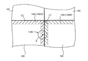
- FIG. 3B is a diagram illustrating boundary areas in the third touch panel and the fourth touch panel shown in FIG. 3A.
- FIG. 3C is a diagram illustrating an example of an exclusive area.
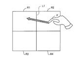
- FIG. 4A is a diagram illustrating an example of an input operation that slides over a plurality of sensor regions.
- FIG. 4B is a diagram illustrating an example of a position detected in the input operation illustrated in FIG. 4A.
- FIG. 5 is a flowchart illustrating an operation example of the combining unit 12.
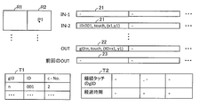
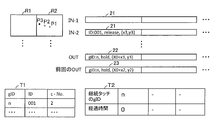
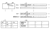
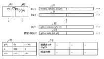
- 6A is a diagram illustrating an example of transition of data in the buffer and the table when the combining unit 12 processes the input operation illustrated in FIG. 4 according to the flow illustrated in FIG. 6B is a diagram illustrating an example of transition of data in the buffer and the table when the combining unit 12 processes the input operation illustrated in FIG. 4 according to the flow illustrated in FIG.
- FIG. 6E is a diagram illustrating an example of transition of data in the buffer and the table when the combining unit 12 processes the input operation illustrated in FIG. 4 according to the flow illustrated in FIG.
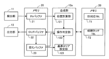
- FIG. 7 is a block diagram illustrating a configuration example of the synthesis unit 12a according to the second embodiment.
- FIG. 8 is a diagram illustrating an example of data when the size of the reference area is recorded in the continuous touch table T2.
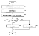
- FIG. 9 is a flowchart illustrating an operation example of the reference area setting unit 123.
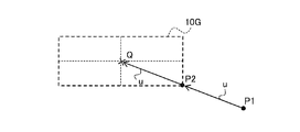
- FIG. 10A is a diagram illustrating an example of a reference area.
- FIG. 10B is a diagram illustrating another example of the reference area.
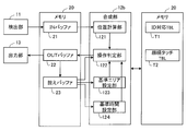
- FIG. 11 is a block diagram illustrating a configuration example of the synthesis unit 12b according to the third embodiment.
- FIG. 12 is a diagram illustrating an example of data when the reference time is recorded in the continuous touch table T2.
- An input device includes a plurality of sensor areas arranged adjacent to each other, a position of contact or approach of an object for each of the plurality of sensor areas, and the object at the position.
- a region combining the plurality of sensor regions based on a detection unit that detects an input operation, a contact or approach position in each of the plurality of sensor regions detected by the detection unit, and an input operation at the position
- a combining unit that determines an input position and an input operation with respect to the whole; and an output unit that outputs the input position and the input operation determined by the combining unit.
- the input operation detected by the detection unit is an input start operation that indicates the start of contact or approach of the object to the sensor area, and an object that has touched or approached the sensor area is detected separately.
- the combining unit is another sensor region adjacent to the one sensor region within a reference time after the release operation is detected in the one sensor region by the detection unit, and the position of the release operation is used as a reference.
- the input start operation is detected in the reference area to be determined, it is determined that the input start operation of the other sensor area is related to the release operation in the one sensor area.
- an input start operation detected in the reference area of another sensor area is related to the release operation within the reference time from the detection of the release operation.
- the input operation is determined.
- the release operation in one sensor region detected by the detection unit and the input start operation in another sensor region are recognized as input operations related to each other in the synthesis unit. For example, when an operation of moving an object from one sensor area to another sensor area is performed, an input operation detected in one sensor area and an input operation detected in another sensor area
- the synthesis unit can recognize that the operation is performed continuously. That is, an input operation over a plurality of adjacent sensor regions can be recognized as an input operation related to each other.
- the combining unit determines whether the position of the release operation detected in the one sensor region is within a boundary area including a boundary between the one sensor region and another adjacent sensor region. be able to.
- the input operation is detected in the other sensor area in the reference area within a reference time from the release operation when the combining unit determines that the release operation is in a boundary area, It can be determined that the input start operation in the other sensor region and the release operation in the one sensor region are related input operations.
- the combining unit may determine a range of the reference area according to a distance between a release operation position in the one sensor area and an input operation position in the one sensor area before the release operation. it can. Thereby, the range of the reference area can be adjusted according to the amount of movement of the object until the release operation. As a result, detection accuracy can be improved.
- the synthesizing unit can determine the reference time according to the distance between the position of the release operation in the one sensor area and the position of the input operation in the sensor area at the position before the release operation.
- the reference time can be adjusted according to the amount of movement of the object until the release operation. As a result, processing efficiency can be improved.
- An information processing apparatus detects, for each of a plurality of sensor regions arranged adjacent to each other, a position of contact or approach of an object and an input operation by the object at the position.
- This is an information processing apparatus that operates in cooperation with the detection unit.
- the information processing apparatus is configured to input an input position with respect to an entire region obtained by combining the plurality of sensor regions based on a contact or approach position in each of the plurality of sensor regions detected by the detection unit and an input operation at the position.
- a combining unit that determines an input operation, and an output unit that outputs the input position and the input operation determined by the combining unit.
- the input operation detected by the detection unit is an input start operation indicating detection of the start of contact or approach of the object to the sensor area, and an object that has been in contact with or approached the sensor area is detected separately. Includes a release operation indicating that it is gone.
- the combining unit is another sensor region adjacent to the one sensor region within a reference time after the release operation is detected in the one sensor region by the detection unit, and the position of the release operation is used as a reference. When the input start operation is detected in the reference area to be determined, it is determined that the input start operation of the other sensor area is related to the release operation in the one sensor area.
- a program for causing a computer to operate as the information processing apparatus is also one embodiment of the present invention.
- the input device can include a plurality of touch panels.
- each of the plurality of touch panels can be configured to have the sensor areas.
- the touch panel may be arranged so that the plurality of sensor regions are on the same plane. Therefore, the input device which can recognize input operation over a some touch panel is realizable. Therefore, for example, the touch panel can be easily increased in size.
- a sensor-equipped display device that includes the above-described input device and a display panel having a display area at a position overlapping the plurality of sensor regions of the input device is also included in the embodiment of the present invention.
- FIG. 1 is a block diagram illustrating a configuration example of an input device according to the first embodiment.
- the input device 1 is an example of an input device having a plurality of sensor regions.
- the input device 1 has a configuration in which each of a plurality of sensor areas is driven to detect an object such as a finger or a pen for each sensor area.
- the input device 1 includes a plurality of touch panels, that is, first to fourth touch panels 101 to 104, a detection unit 11, a synthesis unit 12, and an output unit 13.
- the first to fourth touch panels 101 to 104 have sensor regions R1 to R4, respectively.
- the sensor regions R1 to R4 are portions that detect contact or approach of an object, and are arranged on the same plane in this example.
- the detection unit 11 detects, for each of the plurality of sensor regions R1 to R4, the position of contact or approach of the object with respect to each sensor region and the input operation at that position.
- the detection unit 11 includes first to fourth controllers 111 to 114 provided corresponding to the sensor regions R1 to R4, respectively.
- the detection unit 11 can detect the contact or approach position of an object in each sensor region for each sensor region, for example, by detecting a signal output from an electrode provided in each sensor region. Moreover, the detection part 11 can detect the time series change of the contact or approach of the target object with respect to a sensor area
- the input operation detected by the detection unit 11 can be a contact or approach state at a position where the contact or approach of the object is detected.
- the detection unit 11 performs an input start operation (new touch operation) indicating the start of contact or approach of the object to the sensor region, and an input maintenance operation (ie, maintenance of contact or approach of the object). Hold operation) and a release operation indicating that an object that has been in contact or approached is no longer detected away from the sensor region can be detected.
- the detection unit 11 can determine the relationship between input operations at a plurality of positions. For example, the detection unit 11 can determine an operation from when the object starts contacting or approaching the sensor area until it leaves the sensor area as a series of input operations related to each other. That is, the detection unit 11 can recognize a series of input operations from the input start operation to the release operation as input operations related to each other. For example, the detection unit 11 can record the relevance of the input operation as data by giving a common identifier (ID) to the input operations related to each other.
- ID common identifier
- the combining unit 12 selects the plurality of sensor regions R1 to R4. An input position for the entire combined area and an input operation at each input position are determined. For example, the combining unit 12 converts coordinates (local coordinates) indicating the position of the object detected in each of the plurality of sensor regions R1 to R4 into coordinates (wide area coordinates) of the plurality of sensor regions R1 to R4 as a whole. . Further, the synthesis unit 12 determines the relevance of the input operation in the plurality of sensor regions R1 to R4. That is, the combining unit 12 can detect input operations related to each other among input operations detected in two or more different sensor regions.
- the combining unit 12 detects the release operation in one sensor region among the plurality of sensor regions R1 to R4 by the detection unit 11, and the other unit adjacent to the one sensor region within a reference time. It is determined whether or not an input start operation is detected in the sensor area. Based on the determination result, it is possible to determine whether or not an input operation related to the release operation of one sensor region is performed in another sensor region. For example, if an input start operation is detected in the reference area based on the release operation within another sensor area within the reference time, the synthesis unit 12 performs an input start operation for the other sensor area. And the release operation in the one sensor area can be determined as an input operation.
- the combining unit 12 can recognize input operations related to each other among the input operations detected in the plurality of sensor regions R1 to R4. Therefore, for example, the combining unit 12 performs an input start operation in one sensor region, moves to another sensor region while maintaining contact or approach of the object, and performs a release operation in the other sensor region. Can be recognized as input operations related to each other. In such a case, since the input operation in one sensor region and the input operation in another sensor region are detected independently in the detection unit 11, they are recognized as separate input operations that are not related to each other. The synthesizing unit 12 can recognize that these input operations are a series of input operations related to each other. The relevance of the input operation can be recorded as data by assigning a common identifier (ID) to the combining unit 12, for example, the input operations related to each other.
- ID common identifier
- the output unit 13 outputs the input position and input operation determined by the synthesis unit 12. That is, the input position for the entire surface of the plurality of sensor regions R1 to R4 and the input operation at each input position are output. A continuous input operation over a plurality of sensor regions R1 to R4 can be output as an input operation related to each other. In this example, the output unit 13 outputs the input position and the input operation to the control device 3.
- touch panels 101 to 104 are arranged on the display panel 2 so as to overlap each other.
- the first to fourth sensor areas R1 to R4 of the input device 1 and the display area AA of the display panel are arranged so as to overlap.
- the input device 1 is connected to a control device 3 provided outside the input device 1.
- the input device 1 outputs the coordinates on the touch panels 101 to 104 to the control device 3.
- An image based on the coordinates is displayed on the display panel 2 by the control device 3.
- the display area AA of the display panel 40 is an area where an image is displayed. Pixels for displaying an image are arranged in the display area AA.
- the display panel 40 can be composed of, for example, a liquid crystal panel.
- the liquid crystal panel includes an active matrix substrate, a counter substrate, and a liquid crystal layer provided between the active matrix substrate and the counter substrate.
- the touch panel 100 when the first touch panel 101, the second touch panel 102, the third touch panel 103, and the fourth touch panel 104 are not distinguished, they are collectively referred to as the touch panel 100.
- the first controller 111, the second controller 112, the third controller 113, and the fourth controller 114 are not distinguished, they are collectively referred to as the controller 110.
- the sensing signal of the controller 110 receives a drive signal output from the controller 110 to the drive electrode, and the capacitance between the drive electrode and the sense electrode is observed. is doing.
- the object touches (touches) or approaches the sensor region R the capacitance corresponding to the intersection (node) between the drive electrode and the sense electrode corresponding to the position changes. Thereby, contact or approach can be recognized. Coordinates indicating the position of contact or approach can be calculated from the position of the intersection.
- each of the first to fourth controllers 111 to 114 inputs a drive signal to the drive electrode of the corresponding sensor region, and based on the response signal output from the sense electrode, the object for the corresponding sensor region Detecting contact or approach. Thereby, the detection of the object is performed independently in each of the sensor regions R1 to R4.
- the detection unit 11, the synthesis unit 12, and the output unit 13 can be formed by a circuit such as an IC (Integrated Circuit), for example. That is, the input device 1 can be configured to include a detection circuit, a synthesis circuit, and an output circuit.
- Each of the first to fourth controllers 111 to 114 can be composed of separate ICs. Alternatively, the first to fourth controllers 111 to 114 can be configured in the same IC.
- the synthesizing unit 12 and the output unit 13 can be configured by a computer including a processor and a memory.
- the hardware configurations of the detection unit 11, the synthesis unit 12, and the output unit 13 are not limited to specific ones.
- the detection unit 11, the synthesis unit 12, and the output unit 13 may be configured by one IC (semiconductor chip), or may be configured by at least two or more ICs. It is not always necessary to provide an IC corresponding to each of the detection unit 11, the synthesis unit 12, and the output unit 13. Note that a program that causes a computer to operate as the combining unit 12 and the output unit 13 and a non-transitory recording medium in which such a program is recorded are also one embodiment of the present invention.
- FIG. 2 is a diagram illustrating a detailed configuration example of the synthesis unit illustrated in FIG. 1.
- the combining unit 12 can access the memory 20.
- an IN buffer 21, an OUT buffer 22, a copy buffer 23, an ID correspondence table T1, and a continuous touch table T2 are recorded.
- the combining unit 12 includes a position calculation unit 121 and an operation determination unit 122.
- the IN buffer 21 stores the position of the object for each of the sensor regions R1 to R4 detected by the detection unit 11 and data of the input operation at that position. For example, a record including coordinates (local coordinates) indicating a detection position of an object, input operation, and an ID for identifying an input operation in each sensor area is stored in the IN buffer as data indicating a detection result of one point. Stored.
- the detecting unit 11 updates the data in the IN buffer 21 at a constant cycle, and the synthesizing unit 12 can read the data in the IN buffer 21 at the cycle.
- the data in the IN buffer 21 can be updated and read at a cycle (or sampling rate) in which the detection unit 11 scans or monitors each sensor area to detect the position of contact or approach of the object. .
- the position calculation unit 121 specifies the contact position (detection position) of the target object in the entire plurality of sensor regions R1 to R4. Specifically, the position calculation unit 121 reads out the data stored in the IN buffer 21, and converts the position of the object detected in each sensor area into data indicating the position in the plurality of sensor areas R1 to R4 as a whole. Convert. For example, the position calculation unit 121 converts the coordinates (local coordinates) indicating the position in each sensor area stored in the IN buffer 21 into the coordinates (wide area coordinates) on the coordinate plane set for the entire plurality of sensor areas R1 to R4. ).
- the operation determination unit 122 determines the relevance of the input operations detected in the plurality of sensor regions R1 to R4, and determines the input operation at each detection position based on the determination result. Specifically, the operation determination unit 122 reads the data stored in the IN buffer 21, and obtains the position of the object detected in each of the plurality of sensor regions R1 to R4 and the input operation at each position. it can. Further, by reading data from the IN buffer 21 at a constant cycle, it is possible to grasp the detection timing of input operations in the plurality of sensor regions R1 to R4. The operation determination unit 122 can determine the relevance between the input operations detected in the different sensor regions based on the positional relationship and timing of the input operations detected in the different sensor regions.
- the operation determination unit 122 identifies combinations of input operations related to each other among a plurality of input operations detected in different sensor regions. In this case, the operation determination unit 122 can give the same identifier (in this example, gID) to the input operations related to each other. Further, the operation determination unit 122 determines each input operation according to the determined relationship between the input operations.
- the input operation determined here can include, for example, any of an input start operation, an input maintenance operation, or a release operation. Data indicating the determined input operation and the relationship between the input operations (for example, gID) is stored in the OUT buffer 22 in association with the wide-area coordinates of the detection position specified by the position calculation unit 121.
- the operation determination unit 122 sends, to the ID correspondence table T1, data indicating the correspondence between the gID assigned to identify the input operation in the whole of the plurality of sensor regions R1 to R4 and the ID of the input operation in each sensor region. Store it.
- the OUT buffer 22 stores data indicating the input positions and input operations in the whole of the plurality of sensor regions R1 to R4 determined by the combining unit 12.
- the OUT buffer 22 includes, for example, a record including wide-area coordinates indicating input positions in the entire plurality of sensor areas R1 to R4, data indicating input operations, and an ID (gID) for identifying input operations in the entire sensor areas R1 to R4. Is stored as data indicating the detection result of one point.
- the data stored in the OUT buffer 22 is read by the output unit 13 and output to the outside. Data that has been output by the output unit 13 is copied to the copy buffer 23. As a result, the previously output data is stored in the backup buffer 23.
- the operation determination unit 122 sets the position of the release operation in the boundary area (specifically It is determined whether or not the example is within (described later).
- the identifier (gID) of this release operation is recorded in the continuous touch table T2.
- the operation determination unit 122 periodically refers to the continuous touch table T2 and deletes an identifier (gID) that has passed a predetermined reference time. As a result, the gID of the release operation detected in one sensor area can be stored for the reference time.
- the operation determination unit 122 indicates that the position of the input start operation is the reference area (specific example) of the gID release operation recorded in the continuous touch table T2. It is determined whether or not within the following. Thereby, it can be determined whether or not the release operation and the input start operation are related input operations.
- FIG. 3A is a schematic diagram showing the first to fourth touch panels 101 to 104 shown in FIG.
- the boundary area includes an area 100R between a broken line substantially parallel to the boundary L1 and a boundary L1 that is a predetermined distance away from the boundary L1 in the X axis positive or negative direction, and the Y axis positive or negative direction from the boundary L2.
- This is a region 100R between a broken line substantially parallel to the boundary L2 and a boundary L2 that is a certain distance apart.
- the boundary L ⁇ b> 1 is a boundary between the first touch panel 101 and the second touch panel 102 and between the third touch panel 103 and the fourth touch panel 104.
- the boundary L ⁇ b> 2 is a boundary between the first touch panel 101 and the third touch panel 103 and between the second touch panel 102 and the fourth touch panel 104. That is, the boundary area in the touch panel 100 is an area near the boundary including the boundary with the adjacent touch panel 100.
- a region 103r (100R) including a boundary L1 between the adjacent fourth touch panel 104 and a boundary L2 with the adjacent first touch panel 101 is defined as a boundary area.
- an area 104r (100R) including a boundary L1 between the adjacent third touch panel 103 and a boundary L2 between the adjacent second touch panel 102 is a boundary area.
- the coordinate range of the boundary area in each touch panel 100 can be recorded in advance in the memory 20 or the like accessible by the combining unit 12.
- the boundary area is an area that is set in order to recognize an input operation for moving an object across the boundaries of a plurality of sensor areas, that is, the boundary of the touch panel, as a series of input operations.
- the width of the boundary area can be, for example, the maximum amount of movement of the object that can be detected at the sampling rate of the detection unit 11. Note that the shape of the boundary area is not limited to the example shown in FIG. 3A.
- the operation determining unit 122 may determine that the input start operation is an operation continued from the release operation when the input start operation of the sensor region R of the other touch panel 100 exists within the reference area within the reference time. it can.
- the operation determination unit 122 can recognize both the release operation and the input start operation as input maintaining operations, and can assign the same gID to these input operations. Further, when the input start operation of the sensor area R of the other touch panel 100 does not exist within the reference time within the reference area, the operation determination unit 122 can confirm the release operation.
- the reference area is an area that is set in order to determine whether or not the input start operation within the reference time from the detection of the release operation is a continuation operation of the release operation.
- the reference area can also be called an exclusive area.
- the reference area can be recorded in advance in the memory 20 or the like accessible by the combining unit 12.
- the shape of the reference area is not limited to the circular shape in the above example. For example, a semicircle, a fan shape, a rectangle, and other various shapes are possible.
- the data indicating the reference area can be recorded as a value of the distance from the position of the release operation, for example. Further, as will be described later, the reference area can be dynamically changed according to the detected input operation.
- FIG. 4A a case will be described in which an input operation of sliding over a plurality of sensor regions is performed in a state where an object is in contact with or close to the sensor region.
- the finger F when the finger F is slid from the second sensor region R2 over the boundary L1 to the first sensor region R1, for example, as shown in FIG. 4B, the second sensor region R2 at regular intervals.
- P1, P2, and P3 are sequentially detected by the second controller 112 as contact positions.
- P4 and P5 in the first sensor region R1 are sequentially detected by the first controller 111 as contact positions.
- the contact position P4 is detected S seconds after the detection of the contact position P3.
- the second controller 112 of the detection unit 11 detects the input start operation at P1, the input maintenance operation at P2, and the release operation at P3.
- the first controller 111 of the detection unit 11 detects an input start operation at P4 and a release operation at P5.
- the input operations P1 to P3 and the input operations P4 to P5 are detected separately.
- the synthesizing unit 12 determines the input operations of P1 to P3 and the input operations of P4 to P5 as input operations related to each other. At that time, the combining unit 12 determines whether or not the position of the release operation of P3 is within the boundary area, whether or not the time (S seconds) from the release operation of P3 to the input start operation of P4 is within the reference time, The above determination can be made based on whether or not the position of the input start operation of P4 is within the reference area based on the position of the release operation of P3. If all of these are YES, the combining unit 12 determines that the input operations P1 to P3 and the input operations P4 to P5 are input operations related to each other. Furthermore, the composition unit 12 determines that the input operations of P3 and P4 are input maintaining operations. Thereby, the synthesizing unit 12 can recognize the input operations P1 to P5 as a series of input operations related to each other.
- FIG. 5 is a flowchart showing an operation example of the synthesis unit 12.
- the synthesizer 12 repeats the process shown in FIG. 5 at a predetermined cycle (or sampling rate).
- the synthesis unit 12 determines whether there is a continuous touch (S1).
- a release operation is detected in the boundary area of one sensor region, but this release operation is determined to be a release operation because there is a possibility of continuing to an input operation in another sensor region. Is something that is on hold.
- the continuous touch identifier (gID) is recorded in the continuous touch table T2. Therefore, the composition unit 12 can determine whether or not there is a continuous touch by referring to the continuous touch table T2.
- the composition unit 12 determines whether or not a reference time has elapsed since the continuous touch was detected (S2). For example, the elapsed time or detection time of the continuous touch can be recorded in the continuous touch table T2. In this case, the composition unit 12 can determine the elapse of the reference time by referring to the continuous touch table T2.
- the reference time is a value used as a threshold when determining whether or not the input start operation in the reference area after the release operation is detected is an operation performed continuously after the release operation.
- the reference time is a preset time and can be recorded in advance in the memory 20 or the like. As will be described later, the reference time can be dynamically changed according to the detected input operation.
- the composition unit 12 clears that the continuous touch input operation is hold (input maintenance operation) and releases it (S3). . Specifically, the synthesis unit 12 stores a record including gID of continuous touch, coordinates indicating the position of continuous touch, and data indicating that the input operation is release in the OUT buffer 22. The processes of S2 and S3 are repeatedly executed for all continuous touches recorded in the continuous touch table T2 (until YES in S4). The continuous touch that has passed the reference time by the processing of S1 to S4 is output as a release input operation and determination.
- the composition unit 12 acquires the touch information detected by each of the first to fourth controllers 111 to 114 from the IN buffer 21 (S5).
- the touch information includes, for example, data indicating the identifier (ID) of the input operation in each sensor area, the local coordinates of the touch position in each sensor area, and the status of the input operation.
- a record including the ID, the local coordinates of the touch position, and the status is stored in the IN buffer 21 for each detected touch.
- a new touch input start operation
- hold input maintenance operation
- release release operation
- the position calculation unit 121 of the combining unit 12 converts the local coordinates of the touch position in each sensor area included in the acquired touch information into wide-area coordinates in a coordinate system when the plurality of sensor areas R1 to R4 are one plane. (S6). Thereby, the coordinates of the touch detection position in the whole of the plurality of sensor regions R1 to R4 are obtained.
- the wide-area coordinates can be coordinates used for specifying a position in one sensor area when a plurality of sensor areas R1 to R4 are recognized as one sensor area, for example. Wide area coordinates can also be referred to as composite coordinates.
- the combining unit 12 may calculate the number of touches detected in the plurality of sensor regions R1 to R4 (S6).
- the operation determination unit 122 of the synthesis unit 12 determines an input operation for each of the touches (hereinafter referred to as “detection touch”) detected in the plurality of sensor regions R1 to R4 in the processes of S7 to S19 described below.
- the operation determination unit 122 selects the detected touch records stored in the IN buffer 21 one by one, and determines the input operation for the detected touch of the selected record.
- the operation determination unit 122 determines whether or not the position of the detected touch is within the reference area for the continuous touch (S8). For example, the operation determination unit 122 acquires the coordinates corresponding to the identifier gID of the continuous touch recorded in the continuous touch table T2 from the copy buffer 23. The acquired coordinate of the continuous touch is a sensor region adjacent to the sensor region of the detected touch, and the distance between the position indicating the coordinate of the continuous touch and the position of the detected touch is from the value set as the reference area If it is smaller, the operation determination unit 122 can determine that it is within the reference area (YES in S8).
- the operation determination unit 122 determines YES in S8, the status of the detected touch is determined to be hold (S10), and the gID of the detected touch (identifier in the plurality of sensor regions R1 to R4) is set as the gID of the continuous touch. decide. Data indicating the correspondence between the determined gID and the local ID in the sensor area of the detected touch is recorded in the ID correspondence table T1 (S11).
- the operation determination unit 122 stores in the OUT buffer 22 a record including the gID of the detected touch that has been determined, the global coordinates of the detected touch, and data indicating that the input operation is hold.
- the operation determination unit 122 determines NO in S8, the status of the detected touch is a new touch. In this case, a new gID is given to the detected touch.
- the operation determination unit 122 stores, in the OUT buffer 22, a record including the gID of the newly added detected touch, the global coordinates of the detected touch, and data indicating that the input operation is a new touch.
- the operation determination unit 122 determines whether or not the position of the detected touch is within the boundary area (S13). When the position of the detected touch is within the boundary area (YES in S13), the operation determining unit 122 records the gID of the detected touch as a continuous touch in the continuous touch table T2 (S15). Here, the gID of the detected touch can be acquired from the copy buffer 23, for example. The operation determination unit 122 determines that the status of the detected touch is “hold” (S16). A record including the gID of the detected touch, the global coordinates of the detected touch, and data indicating that the input operation is hold is stored in the OUT buffer 22.
- the operation determination unit 122 determines that the status of the detected touch is release (S14).
- a record including the gID of the detected touch, the global coordinates of the detected touch, and data indicating that the input operation is release is stored in the OUT buffer 22.
- the operation determination unit 122 determines that the status of the detected touch is “hold” (S18).
- a record including the gID of the detected touch, the global coordinates of the detected touch, and data indicating that the input operation is hold is stored in the OUT buffer 22.
- FIGS. 6A to 6E are diagrams showing an example of transition of data in the buffers 21 to 23 and the tables T1 to T2 when the combining unit 12 processes the input operation shown in FIG. 4A according to the flow shown in FIG. 6A to 6E
- IN-1 indicates an IN buffer 21 for storing touch information in the first sensor region R1
- IN-2 indicates an IN buffer 21 for storing touch information in the second sensor region R2.
- OUT indicates the OUT buffer 22, and the previous OUT indicates the buffer buffer 23.
- FIG. 6A shows data in the buffers 21 to 23 and the tables T1 to T2 when a new touch operation is performed at the position P1 in the second sensor region R2.
- a record including the local ID “001”, status “touch”, and local coordinates (x1, y1) of the detected touch detected at P1 of the second sensor region R2 is an IN buffer for the second sensor region R2. 21 is stored.
- the synthesizing unit 12 reads the record in the IN buffer 21 and determines the input positions and input operations of the entire sensor areas R1 to R4.
- the OUT buffer 22 stores a record including the determined input position (X0 + x1, y1), the input operation “touch”, and the newly assigned gID.
- a local ID in the second sensor region R2 of the detected touch and a gID in the entire sensor region R1 to R4 are recorded in association with each other.
- controller No. “2” for identifying the controller 112 is also recorded in association therewith.
- FIG. 6B shows data in the buffers 21 to 23 when the finger F is detected while moving from P1 to P2.
- the record of the detected touch detected at P2 in the second sensor region R2 is stored in the IN buffer 21.
- the synthesizing unit 12 reads the record in the IN buffer 21 and determines the input positions and input operations of the entire sensor areas R1 to R4.
- the OUT buffer 22 stores a record including the determined input position (X0 + x2, y2), input operation “hold”, and gID.
- the data of the ID correspondence table T1 and the continuous touch table T2 are omitted because there is no change.
- FIG. 6C shows data in the buffers 21 to 23 and the tables T1 to T2 when the finger F is detected in a state where the finger F moves from P2 to P3 and away from the second sensor region R2.
- a record including the ID of the detected touch detected in P3, status “release”, and local coordinates (x3, y3) is stored in the IN buffer 21.
- the synthesizing unit 12 reads this and determines the input positions and input operations of the entire sensor regions R1 to R4.
- P3 is determined to be a boundary area (YES in S13 of FIG. 5)
- gID “n” is registered in the continuous touch table T2 (S15)
- the status of the detected touch is determined to be hold (hold) ( S16). Therefore, the OUT buffer 22 stores a record including the input position (X0 + x3, y3), the input operation “hold”, and gID.
- FIG. 6D shows data in the buffers 21 to 23 and the tables T1 to T2 when the finger F leaves the second sensor region R2, enters the first sensor region R1, and is detected at P4.
- a record including the local ID “002” in the first sensor region R1 of the detected touch detected in P4, the status “touch” indicating the new touch, and the local coordinates (x4, y4) is for the first sensor region.
- the synthesizing unit 12 Stored in the IN buffer 21.
- the synthesizing unit 12 reads this, and determines the input positions (wide area coordinates) and input operations of the entire sensor regions R1 to R4.
- the synthesizing unit 12 acquires the position (X0 + x3, y3) of the continuous touch of gID “n” recorded in the continuous touch table T2 from the copy buffer 23.
- the composition unit 12 determines whether or not the position (x4, y4) of the new touch detected in P4 is within the reference area with the position (X0 + x3, y3) of the continuous touch as a reference.
- the position of P4 is determined to be within the reference area for the continuous touch of gID “n” (YES in S8 of FIG. 5).
- the status of the detected touch is determined to be hold (S10).
- the ID correspondence table T1 is updated so that gID “n” is associated with the local ID “002” of P4.
- the gID “n” in the continuous touch table T2 is deleted.
- the OUT buffer 22 stores a record including the input position (x4, y4), the input operation “hold”, and gID.
- FIG. 6E shows data in the buffers 21 to 23 and the tables T1 to T2 when the finger F moves from P4 to P5 and is separated from the first sensor region R1.
- a record including the ID “002” of the detected touch detected in P5, the release status “release”, and the local coordinates (x5, y5) is stored in the IN buffer 21.
- the synthesizing unit 12 reads this and determines the input positions and input operations of the entire sensor regions R1 to R4. At this time, it is determined that the position of P5 is not within the boundary area (NO in S13 of FIG. 5), and the status of the detected touch is determined to be release (S14).
- the OUT buffer 22 stores a record including an input position (x5, y5), an input operation “release”, and gID. There is no change in the contents of the ID correspondence table T1 and the continuous touch table T2.
- the operation example of the synthesis unit 12 has been described above, but the operation of the synthesis unit 12 is not limited to the above example.
- the buffer configuration, the record configuration, and the table configuration are not limited to the above example.
- the combining unit 12 may operate so as to set the detected release operation as a continuous touch.
- the continuous touch table T2 For example, data indicating whether or not there is a continuous touch can be stored in the OUT buffer 22 or other memory.
- input operations may be detected at a plurality of positions simultaneously in one sensor region.
- the reference area used as a reference for determining the relationship between the release operation and the input start operation from the viewpoint of distance is a predetermined value.
- the reference area can be dynamically set according to the distance between the position of the release operation and the position of the input operation before the release operation.
- FIG. 7 is a block diagram illustrating a configuration example of the synthesis unit 12a according to the second embodiment.
- the combining unit 12a further includes a reference area setting unit 123.
- the reference area setting unit 123 determines a reference area based on the release operation detected by the detection unit 11 based on the input position detected in the same sensor area as the release operation before the release operation.
- the operation determination unit 122 uses the reference area determined by the reference area setting unit 123 to determine whether there is an input start operation related to the release operation.
- the reference area setting unit 123 determines the size of the reference area according to the distance between the position of the detected release operation and the position of the input operation detected in the same sensor region before the release operation. Can do. That is, the size of the reference area can be determined according to the amount of movement of the object from the previous detection to the detection of the release operation. For example, the reference area can be set to be larger as the distance between the previous detection position and the release operation detection position is larger. Thereby, the faster the movement of the object, the larger the size of the reference area can be set. Therefore, a reference area having an appropriate size is set according to the movement of the object, and the accuracy of the determination is improved.
- the reference area size is not limited to the position of the input operation detected last time of the release operation.
- the position of the input operation detected two or more times before the detection of the release operation may be used to determine the reference area size.
- the size of the reference area determined by the reference area setting unit 123 can be recorded, for example, in the continuous touch table T2.
- FIG. 8 is a diagram illustrating an example of data when the size of the reference area is recorded in the continuous touch table T2. In the example illustrated in FIG. 8, a value indicating the size of the reference area is also recorded in association with the gID of the continuous touch.
- the form of data for associating the reference area with the gID of the continuous touch is not limited to the continuous touch table T2.
- FIG. 9 is a flowchart showing an operation example of the reference area setting unit 123.
- the reference area setting unit 123 first acquires the coordinates of the detection position of the input operation detected in the same sensor region last time of the target release operation (S21).
- the reference area setting unit 123 refers to an input operation detected before the release operation by referring to the wide-area coordinates of the same gID as the gID of the release operation in the copy buffer 23 storing the data of the previous OUT buffer. The position of can be obtained.
- the reference area setting unit 123 calculates the distance between the target release operation position and the previous input operation position acquired in S21 (S22).
- the reference area setting unit 123 calculates the size W of the reference area based on the distance calculated in S22 (S23).
- a predetermined calculation formula or table may be used for the calculation of the size W of the reference area. For example, when the reference area is a circle having a radius r centered on the position of the release operation as shown in FIG. 3C, the length of the radius r can be determined as the size W of the reference area.
- the reference area setting unit 123 determines whether or not the size W calculated in S23 is smaller than a preset minimum value Wmin (S24). If the size W is smaller than the minimum value Wmin, the size of the reference area is set to the minimum value Wmin (S26). If the size W is not smaller than the minimum value Wmin, the size of the reference area is determined as the size W calculated in S23. can do. Thereby, it can be prevented that the size of the reference area becomes too small to make an accurate determination.
- the reference area size determination process is not limited to the above example.
- the reference area setting unit 123 can determine not only the size of the reference area but also the position and shape. For example, the reference area setting unit 123 specifies a range in which the input operation is likely to be detected next to the release operation based on the input position detected in the same sensor area as the release operation before the release operation. Can do. In this case, the specified range is determined as the reference area.
- the reference area setting unit 123 can determine a range based on a vector connecting the position of the release operation and the position of the input operation (previous input operation) detected before the release operation as the reference area. .
- the reference area setting unit 123 calculates a vector from the position of the previous input operation to the position of the release operation.
- the reference area can be determined based on the position moved by the calculated vector from the position of the release operation. For example, a range within a predetermined distance from a position moved by a vector from the position of the release operation can be determined as the reference area.
- FIG. 10A and 10B are diagrams illustrating examples of reference areas determined by the reference area setting unit 123.
- FIG. 10A a vector u from the position P1 of the previous input operation to the position P2 of the release operation is calculated.
- a circle centered on the position Q obtained by adding the vector u from P1 is determined as the reference area 10F.
- the radius of the circle of the reference area 10F can be a predetermined value. Alternatively, the radius of this circle can be determined based on the length of the vector u.
- a circle having a size corresponding to the amount of movement from P1 to P2 can be set as the reference area.
- data indicating the reference area for example, the coordinates and radius values of the center of the circle can be recorded in the memory 20.
- a rectangle centered at a position Q obtained by adding the vector u from P1 is determined as the reference area 10G.
- the length of the reference area 10G in the x direction can be determined based on the x component of the vector u
- the length of the reference area 10G in the y direction can be determined based on the y component of the vector u.
- the reference time used as a reference for determining the relationship between the release operation and the input start operation from the viewpoint of time is a predetermined value.
- the reference time can be dynamically set according to the distance between the position of the release operation and the position of the input operation before the release operation.
- FIG. 11 is a block diagram illustrating a configuration example of the synthesis unit 12b according to the third embodiment.
- the combining unit 12b further includes a reference area setting unit 123 and a reference time setting unit 124.
- the reference area setting unit 123 can be configured similarly to the second embodiment.
- the reference time setting unit 124 uses a reference time, which is the maximum value of the time during which the status of the release operation by the detection unit 11 is held in the hold, as an input position detected in the same sensor area as the release operation before the release operation. Determine based on.
- the operation determination unit 122 uses the reference time determined by the reference time setting unit 124 to determine whether there is an input start operation associated with the release operation.
- the reference time setting unit 124 determines the length of the reference time according to the distance between the position of the detected release operation and the position of the input operation detected in the same sensor area before the release operation. be able to. That is, the length of the reference time can be determined according to the amount of movement of the object from the previous detection to the detection of the release operation. For example, the reference time can be set shorter as the distance between the previous detection position and the release operation detection position is larger. Thus, the faster the movement of the object, the shorter the reference time can be set. Therefore, a reference time having an appropriate length is set according to the movement of the object, and the processing efficiency is improved.
- the data used to determine the reference time is not limited to the position of the input operation detected in the previous release operation.
- the position of the input operation detected two or more times before the detection of the release operation may be used for determining the reference time.
- the length of the reference time determined by the reference time setting unit 124 can be recorded in, for example, the continuous touch table T2.
- FIG. 12 is a diagram illustrating an example of data when the reference time is recorded in the continuous touch table T2. In the example shown in FIG. 12, a value indicating the reference time is also recorded in association with the gID of the continuous touch.
- both the reference area setting unit 123 and the reference time setting unit 124 are provided.
- only the reference time setting unit 124 may be provided.
- the local coordinates indicating the position in each sensor area detected by the detection unit 11 are converted into the wide-area coordinates on the entire coordinate plane including the plurality of sensor areas.
- the conversion to the wide area coordinates can also be performed by the control device 3.
- a controller is provided in each sensor region.
- a configuration in which a single controller that controls a plurality of sensor regions may be provided.
- a mutual capacitive touch panel is used as an example of the touch panel, but the touch panel may be a self-capacitance system. Further, the touch panel is not limited to the capacitive type. For example, a resistance method, an electromagnetic induction method, an active pen method, an optical method, and other types of touch panels can be applied to the above embodiment.
- the touch panel may be an in-cell method or an out-cell method.
- the display panel is not limited to a liquid crystal panel.
- the display panel may be, for example, an organic EL display, a plasma display, or a display using electrophoresis or MEMS.
- the input device 1 according to the first to third embodiments can be suitably used for a large touch panel.
- the sensor area when the touch panel is increased in size, the sensor area also increases. As the sensor area becomes larger, the time required to scan the sensor area becomes longer due to an increase in resistance of the drive electrode and the sense electrode and an increase in the number of wirings. As a result, it may happen that scanning at the required rate is not possible. Therefore, by dividing the sensor area and detecting the object in each sensor area, the scanning rate of each sensor area can be increased. In such a configuration, by applying the above embodiment, it is possible to accurately recognize input operations continuously over a plurality of sensor regions. Therefore, a large touch panel with few detection errors can be realized.
- the input device 1 is not limited to a large touch panel, and can be used for a small and medium touch panel.
- Various electronic devices including the input device 1 described in the first to third embodiments are also included in the embodiments of the present invention.
- a display device including the input device of the present invention can be applied to a board, an electronic white board, or the like.
- the present invention can be applied to various electronic devices as the independent input device 1 without a display panel.
- the input device can be applied to operation panels, buttons, consoles, and the like of various devices.
Landscapes
- Engineering & Computer Science (AREA)
- General Engineering & Computer Science (AREA)
- Theoretical Computer Science (AREA)
- Human Computer Interaction (AREA)
- Physics & Mathematics (AREA)
- General Physics & Mathematics (AREA)
- User Interface Of Digital Computer (AREA)
Abstract
入力装置(1)は、複数のセンサ領域(R1~R4)の各々について、対象物の位置と入力操作とを検出する検出部(11)と、検出部(11)により検出された複数のセンサ領域の各々における位置と入力操作とに基づいて、複数のセンサ領域を組み合わせた領域全体に対する入力位置及び入力操作を決定する合成部(12)と、出力部(13)とを備える。検出部(11)が検出する入力操作は、入力開始操作及びリリース操作を含む。合成部(12)は、リリース操作が検出されてから基準時間内に、隣接する他のセンサ領域の基準エリア内において入力開始操作が検出された場合、他のセンサ領域の入力開始操作と、リリース操作とが関連する入力操作であると決定する。
Description
本願開示は、タッチパネル等の入力装置において対象物の接触又は接近を検知する技術に関する。
近年、表示パネルの上にタッチパネルを積層した表示装置が広く普及している。また、表示パネルの大型化に伴って、タッチパネルを大型化する技術が提案されている。
特開2013-229010号公報には、複数の検出領域を有する大型のタッチパネルが開示されている。このタッチパネルは、各検出領域に対応するコントローラによって検出領域におけるタッチ位置を検出し、各コントローラが検出されたタッチ位置を用い、そのタッチ位置に対応するタッチパネル全面における位置を算出する。
従来技術では、異なる複数の検出領域でそれぞれにおいて別個に検出された入力操作について互いに関連性を判断し、複数の検出領域にわたる入力操作を正しく認識するための仕組みが十分でなかった。そこで、本願は、複数の検出領域にわたる入力操作を認識することができる入力装置を開示する。
本願開示の入力装置は、互いに隣接して配置された複数のセンサ領域と、前記複数のセンサ領域の各々について、対象物の接触又は接近の位置と、前記位置における前記対象物による入力操作とを検出する検出部と、前記検出部により検出された複数のセンサ領域の各々における接触又は接近の位置と、前記位置における入力操作とに基づいて、前記複数のセンサ領域の全面に対する入力位置及び入力操作を決定する合成部と、前記合成部により決定された入力位置及び入力操作を出力する出力部と、を備える。前記検出部が検出する入力操作は、前記センサ領域への前記対象物の接触又は接近の検出の開始を示す入力開始操作及び、前記センサ領域へ接触又は接近していた対象物が離れて検出されなくなったことを示すリリース操作を含む。前記合成部は、前記検出部により一のセンサ領域でリリース操作が検出されてから基準時間内に、前記一のセンサ領域に隣接する他のセンサ領域であって、当該リリース操作の位置を基準とする基準エリア内において入力開始操作が検出された場合、当該他のセンサ領域の入力開始操作と、前記一のセンサ領域におけるリリース操作とが関連する入力操作であると決定する。
本願開示によれば、複数の検出領域にわたる入力操作を認識することができる入力装置が実現できる。
本発明の一実施形態における入力装置は、互いに隣接して配置された複数のセンサ領域と、前記複数のセンサ領域の各々について、対象物の接触又は接近の位置と、前記位置における前記対象物による入力操作とを検出する検出部と、前記検出部により検出された複数のセンサ領域の各々における接触又は接近の位置と、前記位置における入力操作とに基づいて、前記複数のセンサ領域を組み合わせた領域全体に対する入力位置及び入力操作を決定する合成部と、前記合成部により決定された入力位置及び入力操作を出力する出力部と、を備える。前記検出部が検出する入力操作は、前記センサ領域への前記対象物の接触又は接近の開始の開始を示す入力開始操作及び、前記センサ領域へ接触又は接近していた対象物が離れて検出されなくなったことを示すリリース操作を含む。前記合成部は、前記検出部により一のセンサ領域でリリース操作が検出されてから基準時間内に、前記一のセンサ領域に隣接する他のセンサ領域であって、当該リリース操作の位置を基準とする基準エリア内において入力開始操作が検出された場合、当該他のセンサ領域の入力開始操作と、前記一のセンサ領域におけるリリース操作とが関連する入力操作であると決定する。
上記構成によれば、一のセンサ領域でリリース操作が検出されると、リリース操作の検出から基準時間内に、他のセンサ領域の基準エリア内で検出された入力開始操作は、リリース操作と関連する入力操作として決定される。これにより、検出部で検出された一のセンサ領域におけるリリース操作と、他のセンサ領域における入力開始操作とが、合成部にて、互いに関連する入力操作として認識される。例えば、一のセンサ領域から他のセンサ領域にわたって対象物を接触させたまま移動させる操作がなされた場合、一のセンサ領域で検出される入力操作と、他のセンサ領域で検出される入力操作とが、連続的に行われた操作であることを合成部にて認識することが可能になる。すなわち、互いに隣接する複数のセンサ領域に渡る入力操作を互いに関連する入力操作として認識することが可能になる。
前記合成部は、前記一のセンサ領域で検出された前記リリース操作の位置が、前記一のセンサ領域と、隣接する他のセンサ領域との境界を含む境界エリア内であるか否かを判断することができる。前記合成部は、前記リリース操作が境界エリア内であると判断したときに、前記リリース操作から基準時間内に、前記基準エリア内の前記他のセンサ領域において前記入力開始操作が検出されれば、当該他のセンサ領域の入力開始操作と、前記一のセンサ領域におけるリリース操作とが関連する入力操作であると決定することができる。
これにより、一のセンサ領域の境界付近でリリース操作がされたときに、他のセンサ領域の入力開始操作との関連が判断される。そのため、判断処理を効率よく実行することができる。
前記合成部は、前記一のセンサ領域におけるリリース操作の位置と、前記リリース操作の前の前記一のセンサ領域における入力操作の位置との距離に応じて、前記基準エリアの範囲を決定することができる。これにより、リリース操作に至るまでの対象物の移動量に応じて、基準エリアの範囲を調整することができる。その結果、検出精度を向上させることができる。
前記合成部は、前記一のセンサ領域におけるリリース操作の位置と、前記リリース操作の前の前記位置のセンサ領域における入力操作の位置との距離に応じて、前記基準時間を決定することができる。リリース操作に至るまでの対象物の移動量に応じて、基準時間を調整することができる。その結果、処理効率を向上させることができる。
本願発明の一実施形態における情報処理装置は、互いに隣接して配置された複数のセンサ領域の各々について、対象物の接触又は接近の位置と、前記位置における前記対象物による入力操作とを検出する検出部と連携動作する情報処理装置である。情報処理装置は、前記検出部により検出された複数のセンサ領域の各々における接触又は接近の位置と、前記位置における入力操作とに基づいて、前記複数のセンサ領域を組み合わせた領域の全体に対する入力位置及び入力操作を決定する合成部と、前記合成部により決定された入力位置及び入力操作を出力する出力部と、を備える。前記検出部が検出する入力操作は、前記センサ領域への前記対象物の接触又は接近の開始の検出を示す入力開始操作及び、前記センサ領域へ接触又は接近していた対象物が離れて検出されなくなったことを示すリリース操作を含む。前記合成部は、前記検出部により一のセンサ領域でリリース操作が検出されてから基準時間内に、前記一のセンサ領域に隣接する他のセンサ領域であって、当該リリース操作の位置を基準とする基準エリア内において入力開始操作が検出された場合、当該他のセンサ領域の入力開始操作と、前記一のセンサ領域におけるリリース操作とが関連する入力操作であると決定する。
コンピュータを上記情報処理装置として動作させるためのプログラムも、本発明の実施形態の一つである。
前記入力装置は、複数のタッチパネルを含むことができる。この場合、前記複数のタッチパネルのそれぞれは、前記各センサ領域を有する構成にすることができる。前記複数のセンサ領域が同一面になるように、前記タッチパネルが配置されてもよい。これにより、複数のタッチパネルにわたる入力操作を認識できる入力装置が実現できる。そのため、例えば、タッチパネルの大型化が容易になる。
上記の入力装置と、前記入力装置の前記複数のセンサ領域に重なる位置に表示領域を有する表示パネルとを備えるセンサ付き表示装置も、本発明の実施形態に含まれる。
以下、図面を参照し、本発明の実施の形態を詳しく説明する。図中同一または相当部分には同一符号を付してその説明は繰り返さない。なお、説明を分かりやすくするために、以下で参照する図面においては、構成が簡略化または模式化して示されたり、一部の構成部材が省略されたりしている。また、各図に示された構成部材間の寸法比は、必ずしも実際の寸法比を示すものではない。
<実施形態1>
(入力装置の構成例)
図1は、実施形態1における入力装置の構成例を示すブロック図である。入力装置1は、複数のセンサ領域を有する入力装置の一例である。入力装置1は、複数のセンサ領域のそれぞれを駆動して、センサ領域ごとに、指又はペン等の対象物を検出する構成を有する。具体的には、入力装置1は、複数のタッチパネル、すなわち第1~第4タッチパネル101~104、検出部11、合成部12、及び、出力部13を備える。第1~第4タッチパネル101~104は、それぞれ、センサ領域R1~R4を有する。センサ領域R1~R4は、対象物の接触又は接近を検知する部分であり、本例では、同一面上に配置されている。
(入力装置の構成例)
図1は、実施形態1における入力装置の構成例を示すブロック図である。入力装置1は、複数のセンサ領域を有する入力装置の一例である。入力装置1は、複数のセンサ領域のそれぞれを駆動して、センサ領域ごとに、指又はペン等の対象物を検出する構成を有する。具体的には、入力装置1は、複数のタッチパネル、すなわち第1~第4タッチパネル101~104、検出部11、合成部12、及び、出力部13を備える。第1~第4タッチパネル101~104は、それぞれ、センサ領域R1~R4を有する。センサ領域R1~R4は、対象物の接触又は接近を検知する部分であり、本例では、同一面上に配置されている。
検出部11は、複数のセンサ領域R1~R4の各々について、各センサ領域に対する対象物の接触又は接近の位置と、その位置における入力操作とを検出する。図1に示す例では、検出部11は、センサ領域R1~R4のそれぞれに対応して設けられた、第1~第4コントローラ111~114を有する。
検出部11は、例えば、各センサ領域に設けられた電極から出力される信号を検出することにより、各センサ領域における対象物の接触又は接近の位置を、センサ領域ごとに検出することができる。また、検出部11は、一定時間ごとに、すなわち、所定の周期で、センサ領域を監視又は走査することにより、センサ領域に対する対象物の接触又は接近の時系列変化を検出できる。これにより、検出部11は、対象物が接触又は接近した位置それぞれにおける入力操作を、その前に検出された入力操作に基づいて判定することができる。
ここで、検出部11により検出される入力操作は、対象物の接触又は接近が検出された位置における接触又は接近の状態とすることができる。例えば、検出部11は、入力操作として、対象物のセンサ領域への接触又は接近の開始の開始を示す入力開始操作(新規タッチ操作)、対象物の接触又は接近の維持を示す入力維持操作(ホールド操作)、及び、接触又は接近していた対象物がセンサ領域から離れて検出されなくなったことを示すリリース操作を、検出することができる。
また、検出部11は、複数の位置における入力操作間の関係を判断することができる。例えば、検出部11は、対象物がセンサ領域に接触又は接近を開始してから、センサ領域から離れるまでの動作を、一連の互いに関連した入力操作として判別することができる。すなわち、検出部11は、入力開始操作からリリース操作までの一連の入力操作を、互いに関連した入力操作として認識することができる。検出部11は、例えば、互いに関連する入力操作に共通の識別子(ID)を付与することで、入力操作の関連性を、データとして記録することができる。
合成部12は、検出部11により検出された複数のセンサ領域R1~R4の各々における対象物の接触又は接近の位置と、各位置における入力操作とに基づいて、複数のセンサ領域R1~R4を組み合わせた領域の全体に対する入力位置、及び各入力位置における入力操作を決定する。例えば、合成部12は、複数のセンサ領域R1~R4の各々で検出された対象物の位置を示す座標(ローカル座標)を、複数のセンサ領域R1~R4全体の座標(広域座標)に変換する。また、合成部12は、複数のセンサ領域R1~R4における入力操作の関連性を判定する。すなわち、合成部12は、異なる2つ以上のセンサ領域で検出された入力操作のうち、互いに関連する入力操作を検出することができる。
具体的には、合成部12は、検出部11により複数のセンサ領域R1~R4のうち一のセンサ領域でリリース操作が検出されてから基準時間内に、前記一のセンサ領域に隣接する他のセンサ領域において、入力開始操作が検出されるか否かを判断する。判断結果に基づいて、一のセンサ領域のリリース操作に関連する入力操作が他のセンサ領域でなされた否かを判定することができる。例えば、合成部12は、上記基準時間内に、他のセンサ領域であって上記リリース操作を基準とする基準エリア内において、入力開始操作が検出された場合、当該他のセンサ領域の入力開始操作と、上記一のセンサ領域におけるリリース操作とが関連する入力操作であると決定することができる。
このようにして、合成部12は、複数のセンサ領域R1~R4で検出された入力操作のうち、互いに関連する入力操作を認識することができる。そのため、合成部12は、例えば、一のセンサ領域で入力開始操作がされて対象物の接触又は接近が維持されたまま他のセンサ領域に移動し、他のセンサ領域においてリリース操作がされるまでの一連の入力操作を、互いに関連した入力操作として認識することができる。このような場合、検出部11では、一のセンサ領域における入力操作と、他のセンサ領域における入力操作は、それぞれ独立して検出されるため、互いに関連しない別々の入力操作として認識される。合成部12により、これらの入力操作が、互いに関連する一連の入力操作であることを認識することができる。合成部12、例えば、互いに関連する入力操作に共通の識別子(ID)を付与することで、入力操作の関連性をデータとして記録することができる。
出力部13は、合成部12により決定された入力位置及び入力操作を出力する。すなわち、複数のセンサ領域R1~R4全面に対する入力位置及び、各入力位置における入力操作が出力される。複数のセンサ領域R1~R4にわたる連続した入力操作は、互いに関連する入力操作として出力することができる。本例では、出力部13は、制御装置3に、入力位置及び入力操作を出力する。
図1に示す例では、表示パネル2の上にタッチパネル101~104が重ねて配置される。具体的には、入力装置1の第1~第4センサ領域R1~R4と、表示パネルの表示領域AAが重なるように配置される。入力装置1の第1~第4センサ領域R1~R4の少なくとも一部を表示領域AAと重ねて配置することにより、表示領域AAに表示される画像に対する入力動作を受け付けることができる。
入力装置1は、入力装置1の外部に設けられた制御装置3と接続されている。入力装置1は、タッチパネル101~104における座標を制御装置3に出力する。その座標に基づく画像が、制御装置3によって表示パネル2に表示される。
表示パネル40の表示領域AAは、画像が表示される領域である。表示領域AAには、画像を表示するための画素が配置されている。表示パネル40は、例えば、液晶パネルで構成することができる。液晶パネルは、アクティブマトリクス基板、対向基板、及びアクティブマトリクス基板及び対向基板の間に設けられる液晶層を備える。
以下、第1タッチパネル101、第2タッチパネル102、第3タッチパネル103、及び第4タッチパネル104を区別しないときは、これらを総称して、タッチパネル100と称する。同様に、第1センサ領域R1、第2センサ領域R2、第3センサ領域R3、及び第4センサ領域R4を区別しないときは、これらを総称して、センサ領域Rと称する。また、第1コントローラ111、第2コントローラ112、第3コントローラ113、及び第4コントローラ114を区別しないときは、これらを総称して、コントローラ110と称する。
例えば、タッチパネル100が、相互容量方式の静電容量タッチパネルである場合、コントローラ110がドライブ電極に対して出力する駆動信号を、コントローラ110のセンシング回路が受け取り、ドライブ電極とセンス電極間の容量を観測している。センサ領域Rに対して対象物の接触(タッチ)又は接近があると、その位置に対応するドライブ電極とセンス電極との交点(ノード)に対応における容量が変化する。これにより、接触又は接近を認識できる。その交点の位置から接触又は接近の位置を示す座標を計算することができる。
このように、第1~第4コントローラ111~114の各々は、対応するセンサ領域のドライブ電極に駆動信号を入力し、センス電極から出力される応答信号に基づいて、対応するセンサ領域に対する対象物の接触又は接近を検出する。これにより、センサ領域R1~R4のそれぞれにおいて、独立して、対象物の検出が行われる。
検出部11、合成部12及び出力部13は、例えば、IC(Integrated Circuit)等の回路により形成することができる。すなわち、入力装置1は、検出回路、合成回路、及び出力回路を備える構成にできる。第1~第4コントローラ111~114をそれぞれ、別々のICで構成することができる。又は、第1~第4コントローラ111~114を、同一IC内に構成することもできる。合成部12及び出力部13は、プロセッサ(processor)と、メモリ(memory)を備えるコンピュータにより構成することができる。なお、検出部11、合成部12及び出力部13のハードウエア構成は、特定のものに限定されない。例えば、検出部11、合成部12及び出力部13を1つのIC(半導体チップ)で構成してもよいし、これらを、少なくとも2つ以上のICで構成することもできる。必ずしも、検出部11、合成部12及び出力部13それぞれに対応するICを設ける必要はない。なお、コンピュータを合成部12、及び出力部13として動作させるプログラム、及びそのようなプログラムを記録した非一時的(non-transitory)な記録媒体も、本願発明の実施形態の1つである。
(合成部の詳細な構成例)
図2は、図1に示す合成部の詳細な構成例を示す図である。図2に示す例では、合成部12は、メモリ20にアクセス可能である。メモリ20には、INバッファ21、OUTバッファ22、控えバッファ23、ID対応テーブルT1、及び継続タッチテーブルT2が記録される。合成部12は、位置計算部121と、操作判定部122とを備える。
図2は、図1に示す合成部の詳細な構成例を示す図である。図2に示す例では、合成部12は、メモリ20にアクセス可能である。メモリ20には、INバッファ21、OUTバッファ22、控えバッファ23、ID対応テーブルT1、及び継続タッチテーブルT2が記録される。合成部12は、位置計算部121と、操作判定部122とを備える。
INバッファ21には、検出部11が検出したセンサ領域R1~R4ごとの対象物の位置及びその位置の入力操作のデータが格納される。例えば、対象物の検出位置を示す座標(ローカル座標)、入力操作を示すデータ、及び各センサ領域における入力操作を識別するIDを含むレコードが、1点の検出結果を示すデータとして、INバッファに格納される。
検出部11は、INバッファ21のデータを、一定の周期で更新し、合成部12は、INバッファ21のデータを、その周期で読み込むことができる。例えば、検出部11が各センサ領域を走査または監視して、対象物の接触又は接近の位置を検出する周期(または、サンプリングレート)で、INバッファ21のデータの更新及び読み込みをすることができる。
位置計算部121は、複数のセンサ領域R1~R4全体における対象物の接触又は接近の位置(検出位置)を特定する。具体的には、位置計算部121は、INバッファ21に格納されたデータを読み出して、各センサ領域において検出された対象物の位置を、複数のセンサ領域R1~R4全体における位置を示すデータに変換する。例えば、位置計算部121は、INバッファ21に格納された各センサ領域における位置を示す座標(ローカル座標)を、複数のセンサ領域R1~R4全体に対して設定された座標面における座標(広域座標)に変換することができる。
操作判定部122は、複数のセンサ領域R1~R4で検出された入力操作の関連性を判断し、判断結果に基づいて各検出位置における入力操作を決定する。具体的には、操作判定部122は、INバッファ21に格納されたデータを読み出して、複数のセンサ領域R1~R4それぞれにおいて検出された対象物の位置及び各位置における入力操作を取得することができる。また、INバッファ21から一定の周期でデータを読み出すことで、複数のセンサ領域R1~R4における入力操作の検出タイミングを把握することができる。操作判定部122は、異なる複数のセンサ領域において検出された複数の入力操作の位置関係及びタイミングに基づいて、異なるセンサ領域で検出された入力操作間の関連性を決定することができる。
例えば、操作判定部122は、異なるセンサ領域で検出された複数の入力操作のうち、互いに関連する入力操作の組み合わせを特定する。この場合、操作判定部122は、互いに関連する入力操作に対して、同じ識別子(本例では、gIDとする)を付与することができる。また、操作判定部122は、決定した入力操作間の関連性に従って、各入力操作を決定する。ここで決定される入力操作には、例えば、入力開始操作、入力維持操作、又はリリース操作のいずれかを含めることができる。決定された入力操作及び入力操作間の関係を示すデータ(例えば、gID)は、位置計算部121が特定した検出位置の広域座標と対応づけてOUTバッファ22に格納される。また、操作判定部122は、複数のセンサ領域R1~R4全体における入力操作を識別するために付与したgIDと、各センサ領域における入力操作のIDとの対応を示すデータを、ID対応テーブルT1へ格納しておく。
これにより、OUTバッファ22には、合成部12で決定された、複数のセンサ領域R1~R4全体における入力位置及び入力操作を示すデータが、格納される。OUTバッファ22には、例えば、複数のセンサ領域R1~R4全体における入力位置を示す広域座標、入力操作を示すデータ、及びセンサ領域R1~R4全体における入力操作を識別するID(gID)を含むレコードが、1点の検出結果を示すデータとして、格納される。
OUTバッファ22に格納されたデータは、出力部13によって読み出され、外部へ出力される。出力部13による出力が完了したデータは、控えバッファ23にコピーされる。これにより、控えバッファ23には、前回出力したデータが保存される。
上記構成において、操作判定部122は、複数のセンサ領域R1~R4のうち一のセンサ領域において検出されたリリース操作のデータがINバッファに格納されると、このリリース操作の位置が境界エリア(具体例は後述)内か否かを判断する。リリース操作の位置が境界エリア内である場合、このリリース操作の識別子(gID)を継続タッチテーブルT2に記録する。操作判定部122は、継続タッチテーブルT2を定期的に参照し、予め決められた基準時間を経過した識別子(gID)は削除するようにする。これにより、一のセンサ領域において検出されたリリース操作のgIDを基準時間だけ、保存することができる。また、操作判定部122は、入力開始操作のデータがINバッファに格納された場合に、その入力開始操作の位置が、継続タッチテーブルT2に記録されているgIDのリリース操作の基準エリア(具体例は後述)内であるか否かを判断する。これにより、リリース操作と入力開始操作が関連する入力操作であるか否かを判断することができる。
(境界エリアの例)
ここで、境界エリアについて図3Aを用いて説明する。図3Aは、図1に示す第1~第4タッチパネル101~104を示した模式図である。境界エリアは、タッチパネル100において、境界L1からX軸正又は負方向に一定距離だけ離れた境界L1に略平行な破線と境界L1との間の領域100Rと、境界L2からY軸正又は負方向に一定距離だけ離れた境界L2に略平行な破線と境界L2との間の領域100Rである。境界L1は、第1タッチパネル101と第2タッチパネル102の間と、第3タッチパネル103と第4タッチパネル104の間の境界である。また、境界L2は、第1タッチパネル101と第3タッチパネル103の間と、第2タッチパネル102と第4タッチパネル104の間の境界である。つまり、タッチパネル100における境界エリアは、隣接するタッチパネル100との境界を含む境界近傍の領域である。
ここで、境界エリアについて図3Aを用いて説明する。図3Aは、図1に示す第1~第4タッチパネル101~104を示した模式図である。境界エリアは、タッチパネル100において、境界L1からX軸正又は負方向に一定距離だけ離れた境界L1に略平行な破線と境界L1との間の領域100Rと、境界L2からY軸正又は負方向に一定距離だけ離れた境界L2に略平行な破線と境界L2との間の領域100Rである。境界L1は、第1タッチパネル101と第2タッチパネル102の間と、第3タッチパネル103と第4タッチパネル104の間の境界である。また、境界L2は、第1タッチパネル101と第3タッチパネル103の間と、第2タッチパネル102と第4タッチパネル104の間の境界である。つまり、タッチパネル100における境界エリアは、隣接するタッチパネル100との境界を含む境界近傍の領域である。
従って、例えば、図3Bに示すように、第3タッチパネル103において、隣接する第4タッチパネル104との境界L1と、隣接する第1タッチパネル101との境界L2を含む領域103r(100R)が境界エリアとなる。また、第4タッチパネル104において、隣接する第3タッチパネル103との境界L1と、隣接する第2タッチパネル102との境界L2を含む領域104r(100R)が境界エリアとなる。各タッチパネル100における境界エリアの座標範囲は、合成部12がアクセス可能なメモリ20等に予め記録しておくことができる。
境界エリアは、複数のセンサ領域の境界、すなわち、タッチパネルの境界を跨ぐよう対象物を移動させる入力操作を、一連の入力操作として認識するために設定されるエリアである。あるセンサ領域の境界エリアにおいてリリース操作が検出された場合は、隣接するセンサ領域で、入力操作が継続される可能性があると判断できる。そのため、境界エリアの幅は、例えば、検出部11のサンプリングレートで検出され得る対象物の最大の移動量とすることができる。なお、境界エリアの形状は、図3Aに示す例に限定されない。
(基準エリアの例)
ここで、基準エリアについて説明する。例えば、図3Cに示すように、第3タッチパネル103の第3センサ領域R3におけるリリース操作の位置Sの座標を中心として一定の半径を有する円形状の領域10Eが基準エリアとして設定される。基準エリア10Eは、例えば人差し指の腹部分程度の大きさとすることができるが、基準エリアの大きさはこれに限定されない。操作判定部122は、基準エリア内に他のタッチパネル100のセンサ領域Rの入力開始操作が基準時間内に存在する場合、その入力開始操作を、リリース操作から継続した操作であると判断することができる。この場合、操作判定部122は、これらのリリース操作及び入力開始操作を、いずれも入力維持操作と認識し、これらの入力操作に、同じgIDを付与することができる。また、基準エリア内に、他のタッチパネル100のセンサ領域Rの入力開始操作が、基準時間内に存在しない場合、操作判定部122は、リリース操作を確定することができる。
ここで、基準エリアについて説明する。例えば、図3Cに示すように、第3タッチパネル103の第3センサ領域R3におけるリリース操作の位置Sの座標を中心として一定の半径を有する円形状の領域10Eが基準エリアとして設定される。基準エリア10Eは、例えば人差し指の腹部分程度の大きさとすることができるが、基準エリアの大きさはこれに限定されない。操作判定部122は、基準エリア内に他のタッチパネル100のセンサ領域Rの入力開始操作が基準時間内に存在する場合、その入力開始操作を、リリース操作から継続した操作であると判断することができる。この場合、操作判定部122は、これらのリリース操作及び入力開始操作を、いずれも入力維持操作と認識し、これらの入力操作に、同じgIDを付与することができる。また、基準エリア内に、他のタッチパネル100のセンサ領域Rの入力開始操作が、基準時間内に存在しない場合、操作判定部122は、リリース操作を確定することができる。
このように、基準エリアは、リリース操作の検出から基準時間内の入力開始操作を、このリリース操作の継続操作であるか否かを判断するために設定されるエリアである。基準エリアは、排他エリアと呼ぶこともできる。基準エリアは、合成部12がアクセス可能なメモリ20等に予め記録しておくことができる。なお、基準エリアの形状は、上記例の円形に限られない。例えば、半円、扇型、矩形その他様々な形状が可能である。また基準エリアを示すデータは、例えば、リリース操作の位置からの距離の値として記録することもできる。さらに、後述するように、検出された入力操作に応じて基準エリアを動的に変更することもできる。
(動作例)
一例として、図4Aに示すように、対象物をセンサ領域に接触または接近させた状態で、複数のセンサ領域にわたってスライドする入力操作がなされた場合について説明する。図4Aにおいて、第2センサ領域R2から境界L1の上を通り、第1センサ領域R1まで指Fをスライドさせた場合、例えば、図4Bに示すように、一定時間ごとに、第2センサ領域R2におけるP1,P2,P3が接触位置として第2コントローラ112によって順次検出される。さらに、第1センサ領域R1におけるP4,P5が接触位置として第1コントローラ111によって順次検出される。指Fが境界L1の上を通る際、接触位置P3の検出のS秒後に、接触位置P4が検出されるとする。
一例として、図4Aに示すように、対象物をセンサ領域に接触または接近させた状態で、複数のセンサ領域にわたってスライドする入力操作がなされた場合について説明する。図4Aにおいて、第2センサ領域R2から境界L1の上を通り、第1センサ領域R1まで指Fをスライドさせた場合、例えば、図4Bに示すように、一定時間ごとに、第2センサ領域R2におけるP1,P2,P3が接触位置として第2コントローラ112によって順次検出される。さらに、第1センサ領域R1におけるP4,P5が接触位置として第1コントローラ111によって順次検出される。指Fが境界L1の上を通る際、接触位置P3の検出のS秒後に、接触位置P4が検出されるとする。
この場合、検出部11の第2コントローラ112は、P1における入力開始操作、P2における入力維持操作、及びP3におけるリリース操作を検出する。検出部11の第1コントローラ111は、P4における入力開始操作及びP5におけるリリース操作を検出する。このように、P1~P3の入力操作と、P4~P5の入力操作は、それぞれ別々に検出される。
合成部12は、これらのP1~P3の入力操作及び、P4~P5の入力操作を、互いに関連する入力操作と決定する。その際、合成部12は、P3のリリース操作の位置が境界エリア内であるか否か、P3のリリース操作からP4の入力開始操作までの時間(S秒)が、基準時間内か否か、及び、P3のリリース操作の位置を基準とする基準エリア内に、P4の入力開始操作の位置があるか否か、に基づいて、上記の決定をすることができる。これらが全てYESの場合、合成部12は、P1~P3の入力操作及び、P4~P5の入力操作を、互いに関連する入力操作であると決定する。さらに合成部12は、P3及びP4の入力操作を、入力維持操作と決定する。これにより、合成部12では、P1~P5の入力操作を、互いに関連する一連の入力操作と認識することができる。
図5は、合成部12の動作例を示すフローチャートである。合成部12は、図5に示す処理を、所定の周期(またはサンプリングレート)で繰り返す。図5に示す例では、まず、合成部12は、継続タッチがあるか否かを判断する(S1)。ここで、継続タッチは、一のセンサ領域の境界エリアにおいてリリース操作が検出されているが、このリリース操作は、他のセンサ領域の入力操作に継続する可能性があるためにリリース操作と決定することを保留にしているものである。継続タッチの識別子(gID)は、上記の継続タッチテーブルT2に記録される。そのため、合成部12は、上記の継続タッチテーブルT2を参照することにより、継続タッチがあるか否かを判断することができる。
継続タッチがある場合、合成部12は、継続タッチが検出されてから基準時間が経過しているか否かを判断する(S2)。例えば、継続タッチテーブルT2に継続タッチの経過時間又は検出時刻を記録することができる。この場合、合成部12は、継続タッチテーブルT2を参照することで、基準時間の経過を判断することができる。
ここで、基準時間は、リリース操作検出後の基準エリア内の入力開始操作が、このリリース操作に継続して行われる操作か否かを判断する際に閾値として用いられる値である。基準時間は、予め設定された時間であり、メモリ20等に予め記録しておくことができる。なお、後述するように、検出された入力操作に応じて基準時間を動的に変更することもできる。
継続タッチが基準時間を経過している場合(S2でYES)、合成部12は、継続タッチの入力操作がホールド(入力維持操作)となっているのをクリアして、リリースとする(S3)。具体的には、合成部12は、継続タッチのgIDと、継続タッチの位置を示す座標、及び、入力操作がリリースであることを示すデータとを含むレコードをOUTバッファ22に格納する。S2、S3の処理は、継続タッチテーブルT2に記録されている全ての継続タッチについて(S4でYESとなるまで)繰り返し実行される。S1~S4の処理により、基準時間を経過した継続タッチは、リリースの入力操作と決定として出力される。
S5にて、合成部12は、第1~第4コントローラ111~114のそれぞれで検出されたタッチ情報を、INバッファ21から取得する(S5)。タッチ情報には、例えば、各センサ領域における入力操作の識別子(ID)、各センサ領域におけるタッチ位置のローカル座標、入力操作のステータスを示すデータが含まれる。これらのID、タッチ位置のローカル座標及びステータスを含むレコードが、検出されたタッチごとにINバッファ21に格納される。なお、ここでは、一例として、ステータスとして、新規タッチ(入力開始操作)、ホールド(入力維持操作)、又は、リリース(リリース操作)のいずれかが検出される場合について説明する。
合成部12の位置計算部121は、取得したタッチ情報に含まれる各センサ領域におけるタッチ位置のローカル座標を、複数のセンサ領域R1~R4を1面とした場合の座標系の広域座標に変換する(S6)。これにより、複数のセンサ領域R1~R4全体におけるタッチの検出位置の座標が得られる。なお、広域座標は、例えば、複数のセンサ領域R1~R4を1つのセンサ領域として認識した場合に、この1つのセンサ領域における位置を特定するのに用いられる座標とすることができる。広域座標は、合成座標と称することもできる。合成部12は、複数のセンサ領域R1~R4において検出されたタッチの数を算出してもよい(S6)。
合成部12の操作判定部122は、下記のS7~S19の処理において、複数のセンサ領域R1~R4において検出されたタッチ(以下、「検出タッチ」と称する)それぞれについて、入力操作を決定する。操作判定部122は、INバッファ21に格納されている検出タッチのレコードを1つずつ選択し、選択したレコードの検出タッチについて入力操作を判断する。
検出タッチのステータスが、新規タッチの場合(S7でYES)、操作判定部122は、この検出タッチの位置が、継続タッチの基準エリア内か否かを判断する(S8)。例えば、操作判定部122は、継続タッチテーブルT2に記録されている継続タッチの識別子gIDに対応する座標を、控えバッファ23から取得する。この取得した継続タッチの座標が、検出タッチのセンサ領域に隣接するセンサ領域であって、かつ、継続タッチの座標を示す位置と検出タッチの位置との距離が、基準エリアとして設定された値より小さい場合、操作判定部122は、基準エリア内である(S8でYES)と判断することができる。
操作判定部122は、S8でYESと判断した場合、この検出タッチのステータスは、ホールドに決定し(S10)、検出タッチのgID(複数のセンサ領域R1~R4における識別子)を継続タッチのgIDと決定する。この決定したgIDと、検出タッチのセンサ領域におけるローカルなIDとの対応関係を示すデータは、ID対応テーブルT1に記録される(S11)。操作判定部122は、決定した検出タッチのgID、検出タッチの広域座標、及び、入力操作がホールドであることを示すデータを含むレコードを、OUTバッファ22に格納する。
操作判定部122は、S8でNOと判断した場合、この検出タッチのステータスは、新規タッチとする。この場合、検出タッチに新たなgIDが付与される。操作判定部122は、新たに付与された検出タッチのgID、検出タッチの広域座標、及び、入力操作が新規タッチであることを示すデータを含むレコードを、OUTバッファ22に格納する。
検出タッチのステータスが、リリースの場合(S12でYES)、操作判定部122は、検出タッチの位置が境界エリア内か否かを判断する(S13)。検出タッチの位置が境界エリア内の場合(S13でYES)、操作判定部122は、検出タッチのgIDを継続タッチとして継続タッチテーブルT2へ記録する(S15)。ここで、検出タッチのgIDは、例えば、控えバッファ23から取得することができる。操作判定部122は、この検出タッチのステータスをホールドと決定する(S16)。検出タッチのgID、検出タッチの広域座標、及び、入力操作がホールドであることを示すデータを含むレコードが、OUTバッファ22に格納される。一方、検出タッチの位置が境界エリア内でない場合(S13でNO)、操作判定部122は、この検出タッチのステータスをリリースと決定する(S14)。検出タッチのgID、検出タッチの広域座標、及び、入力操作がリリースであることを示すデータを含むレコードが、OUTバッファ22に格納される。
検出タッチのステータスが、ホールドの場合(S17でYES)、操作判定部122は、この検出タッチのステータスをホールドと決定する(S18)。検出タッチのgID、検出タッチの広域座標、及び、入力操作がホールドであることを示すデータを含むレコードが、OUTバッファ22に格納される。
以上のS7~S18の処理が、INバッファ21に格納された全てのレコードについて(S19でYESとなるまで)、繰り返される。上記処理により、ある一つのセンサ領域の境界エリアでリリース操作が検出されたとき、とりあえずリリース操作のステータスをホールドにして出力しながら、基準時間だけ待って、他のセンサ領域にて継続する入力操作が開始されるか否かを判断することができる。すなわち、検出されたリリースは、最大で基準時間は、ホールドとされる。基準時間内に、基準エリア内の他のセンサ領域において入力開始操作が検出された場合、この他のセンサ領域の入力開始操作と、上記一のセンサ領域で検出されたリリース操作とが関連する入力操作であると決定される。この場合、リリース操作を識別するgIDが、新たに基準エリア内で開始された入力操作に継続される。基準時間経過後も、基準エリア内に入力がない場合、リリース処理が実行される。
(バッファデータの遷移例)
図6A~図6Eは、図4Aに示す入力操作を、図5に示すフローに従って合成部12が処理した場合のバッファ21~23及びテーブルT1~T2のデータの遷移の一例を示す図である。図6A~図6Eにおいて、IN-1は、第1センサ領域R1におけるタッチ情報を格納するINバッファ21、IN-2は、第2センサ領域R2におけるタッチ情報を格納するINバッファ21、…を示している。OUTは、OUTバッファ22、前回のOUTは、控えバッファ23を示している。
図6A~図6Eは、図4Aに示す入力操作を、図5に示すフローに従って合成部12が処理した場合のバッファ21~23及びテーブルT1~T2のデータの遷移の一例を示す図である。図6A~図6Eにおいて、IN-1は、第1センサ領域R1におけるタッチ情報を格納するINバッファ21、IN-2は、第2センサ領域R2におけるタッチ情報を格納するINバッファ21、…を示している。OUTは、OUTバッファ22、前回のOUTは、控えバッファ23を示している。
図6Aは、第2センサ領域R2において、P1の位置に新規にタッチ操作がされた場合のバッファ21~23及びテーブルT1~T2のデータを示す。この場合、第2センサ領域R2のP1で検出された検出タッチのローカルなID「001」、ステータス「touch」、ローカル座標(x1,y1)を含むレコードが、第2センサ領域R2用のINバッファ21に格納される。合成部12がこのINバッファ21のレコードを読み込み、センサ領域R1~R4全体の入力位置及び入力操作を決定する。OUTバッファ22には、その決定した入力位置(X0+x1,y1)、入力操作「touch」と、新たに付与されたgIDを含むレコードが格納される。ID対応テーブルT1には、検出タッチの第2センサ領域R2にローカルなIDと、センサ領域R1~R4全体におけるgIDとが対応付けられて記録される。ここでは、コントローラ112を識別するコントローラNo「2」もさらに対応づけて記録される。
図6Bは、指FがP1からP2に移動した状態で検出された場合のバッファ21~23のデータを示す。この場合、第2センサ領域R2のP2で検出された検出タッチのレコードが、INバッファ21に格納される。合成部12がこのINバッファ21のレコードを読み込み、センサ領域R1~R4全体の入力位置及び入力操作を決定する。OUTバッファ22には、その決定した入力位置(X0+x2,y2)、入力操作「hold」と、gIDを含むレコードが格納される。ID対応テーブルT1及び、継続タッチテーブルT2のデータは変化がないので省略している。
図6Cは、指FがP2からP3に移動して第2センサ領域R2から離れた状態で検出された場合のバッファ21~23及びテーブルT1~T2のデータを示す。この場合、P3で検出された検出タッチのID、ステータス「release」、ローカル座標(x3,y3)を含むレコードが、INバッファ21に格納される。合成部12が、これを読み込んで、センサ領域R1~R4全体の入力位置及び入力操作を決定する。このとき、P3は、境界エリアと判断され(図5のS13でYES)、継続タッチテーブルT2へgID「n」が登録(S15)され、検出タッチのステータスがホールド(hold)に決定される(S16)。そのため、OUTバッファ22には、入力位置(X0+x3,y3)、入力操作「hold」と、gIDを含むレコードが格納される。
図6Dは、指Fが第2センサ領域R2を離れ、第1センサ領域R1に入ってP4で検出された場合のバッファ21~23及びテーブルT1~T2のデータを示す。この場合、P4で検出された検出タッチの第1センサ領域R1におけるローカルなID「002」、新規タッチを示すステータス「touch」、ローカル座標(x4,y4)を含むレコードが、第1センサ領域用のINバッファ21に格納される。合成部12が、これを読み込んで、センサ領域R1~R4全体の入力位置(広域座標)及び入力操作を決定する。さらに合成部12は、継続タッチテーブルT2に記録されたgID「n」の継続タッチの位置(X0+x3,y3)を控えバッファ23から取得する。合成部12は、P4で検出された新規タッチの位置(x4,y4)が、継続タッチの位置(X0+x3,y3)を基準とする基準エリア内か否かを判断する。本例では、P4の位置は、gID「n」の継続タッチの基準エリア内と判断される(図5のS8でYES)。検出タッチのステータスは、ホールド(hold)に決定される(S10)。また、gID「n」はP4のローカルID「002」と対応付けられるようにID対応テーブルT1が更新される。継続タッチテーブルT2のgID「n」は、削除される。OUTバッファ22には、入力位置(x4,y4)、入力操作「hold」と、gIDを含むレコードが格納される。
図6Eは、指Fが、P4からP5に移動して第1センサ領域R1から離れた状態が検出された場合のバッファ21~23及びテーブルT1~T2のデータを示す。この場合、P5で検出された検出タッチのID「002」、リリースのステータス「release」、ローカル座標(x5,y5)を含むレコードが、INバッファ21に格納される。合成部12が、これを読み込んで、センサ領域R1~R4全体の入力位置及び入力操作を決定する。このとき、P5の位置は、境界エリア内ではないと判断され(図5のS13でNO)、検出タッチのステータスがリリース(release)に決定される(S14)。OUTバッファ22には、入力位置(x5,y5)、入力操作「release」と、gIDを含むレコードが格納される。ID対応テーブルT1と継続タッチテーブルT2の内容に変化はない。
以上、合成部12の動作例を説明したが、合成部12の動作は、上記例に限定されない。例えば、バッファ構成、レコード構成、及びテーブル構成は、上記例に限定されない。また、検出部11でリリース操作が検出された場合に、必ずしも境界エリア内か否かの判断を行わなくてもよい。例えば、図5のS12でYESの場合は、検出されたリリース操作を、継続タッチとして設定するよう合成部12が動作してもよい。また、継続タッチテーブルT2を必ずしも設ける必要はない。例えば、継続タッチがあるか否かを示すデータを、OUTバッファ22又はその他のメモリにて、格納しておくこともできる。また、上記例において、1つのセンサ領域で、同時に複数の位置で入力操作が検出されてもよい。
<実施形態2>
上記実施形態1では、リリース操作と入力開始操作との関連性を距離の観点から判断するための基準として用いる基準エリアは、予め決められた値であった。本実施形態2では、この基準エリアは、リリース操作の位置と、そのリリース操作の前の入力操作の位置との距離に応じて動的に設定することができる。
上記実施形態1では、リリース操作と入力開始操作との関連性を距離の観点から判断するための基準として用いる基準エリアは、予め決められた値であった。本実施形態2では、この基準エリアは、リリース操作の位置と、そのリリース操作の前の入力操作の位置との距離に応じて動的に設定することができる。
図7は、実施形態2における合成部12aの構成例を示すブロック図である。合成部12aは、基準エリア設定部123をさらに備える。基準エリア設定部123は、検出部11で検出されたリリース操作を基準とする基準エリアを、当該リリース操作の前にリリース操作と同じセンサ領域で検出された入力位置に基づいて決定する。操作判定部122は、基準エリア設定部123により決定された基準エリアを用いて、リリース操作と関連する入力開始操作の有無を判断する。
基準エリア設定部123は、例えば、検出されたリリース操作の位置と、このリリース操作の前に同じセンサ領域で検出された入力操作の位置との距離に応じて、基準エリアのサイズを決定することができる。すなわち、前回の検出からリリース操作の検出に至るまでの対象物の移動量に応じて、基準エリアのサイズを決定することができる。例えば、前回検出位置とリリース操作検出位置との距離が大きい程、基準エリアのサイズが大きくなるように設定することができる。これにより、対象物の動きが速いほど、基準エリアのサイズを大きく設定することができる。そのため、対象物の動きの応じて適切なサイズの基準エリアが設定され、判断の精度が向上する。
同様に、前回検出位置とリリース操作検出位置との距離が小さい程、基準エリアのサイズが小さくなるように設定することも可能である。なお、基準エリアサイズの決定に用いられるデータは、リリース操作の前回に検出された入力操作の位置に限られない。例えば、リリース操作の検出の2回以上前に検出された入力操作を位置が、基準エリアサイズの決定に用いられてもよい。
基準エリア設定部123により決定された基準エリアのサイズは、例えば、継続タッチテーブルT2に記録することができる。図8は、継続タッチテーブルT2に基準エリアのサイズが記録される場合のデータの例を示す図である。図8に示す例では、継続タッチのgIDに対応付けて、基準エリアのサイズを示す値も記録される。なお、基準エリアと継続タッチのgIDとを対応付けるデータの形態は、上記継続タッチテーブルT2に限られない。
図9は、基準エリア設定部123の動作例を示すフローチャートである。図9に示す例では、基準エリア設定部123は、まず、対象とするリリース操作の前回に同じセンサ領域で検出された入力操作の検出位置の座標を取得する(S21)。例えば、基準エリア設定部123は、前回のOUTバッファのデータを保存している控えバッファ23におけるリリース操作のgIDと同じgIDの広域座標を参照することにより、リリース操作の前に検出された入力操作の位置を取得することができる。
基準エリア設定部123は、対象とするリリース操作の位置と、S21で取得した前回の入力操作の位置との距離を計算する(S22)。基準エリア設定部123は、S22で計算された距離に基づいて、基準エリアのサイズWを計算する(S23)。この基準エリアのサイズWの計算には、例えば、予め決められた計算式又はテーブルを用いてもよい。例えば、基準エリアが、図3Cに示すように、リリース操作の位置を中心とする半径rの円である場合、この半径rの長さを、基準エリアのサイズWとして決定することができる。
基準エリア設定部123は、S23で計算したサイズWが、予め設定された最小値Wminより小さいか否かを判断する(S24)。サイズWが最小値Wminより小さい場合は、基準エリアのサイズを最小値Wminとし(S26)、サイズWが最小値Wminより小さくない場合は、基準エリアのサイズをS23で計算されたサイズWに決定することができる。これにより、基準エリアのサイズが小さくなりすぎて正確な判断ができなくなることを防ぐことができる。なお、基準エリアのサイズの決定処理は、上記の例に限られない。
(変形例)
基準エリア設定部123は、基準エリアのサイズだけでなく、位置や形状等も決定することができる。例えば、基準エリア設定部123は、リリース操作の前にリリース操作と同じセンサ領域で検出された入力位置に基づいて、リリース操作の次に入力操作が検出される可能性の高い範囲を特定することができる。この場合、特定した範囲が基準エリアに決定される。
基準エリア設定部123は、基準エリアのサイズだけでなく、位置や形状等も決定することができる。例えば、基準エリア設定部123は、リリース操作の前にリリース操作と同じセンサ領域で検出された入力位置に基づいて、リリース操作の次に入力操作が検出される可能性の高い範囲を特定することができる。この場合、特定した範囲が基準エリアに決定される。
一例として、基準エリア設定部123は、リリース操作の位置と、リリース操作の前に検出された入力操作(前回入力操作)の位置とを結ぶベクトルに基づく範囲を、基準エリアに決定することができる。この場合、基準エリア設定部123は、前回入力操作の位置からリリース操作の位置に向かうベクトルを計算する。リリース操作の位置から、計算されたベクトルだけ移動した位置に基づいて基準エリアを決定することができる。例えば、リリース操作の位置からベクトル分移動した位置から所定の距離内の範囲を基準エリアに決定することができる。
図10A及び図10Bは、基準エリア設定部123で決定される基準エリアの例を示す図である。図10Aに示す例では、前回入力操作の位置P1からリリース操作の位置P2へのベクトルuが計算される。P1からベクトルuを足した位置Qを中心とする円が基準エリア10Fとして決定される。基準エリア10Fの円の半径は、予め決められた値とすることができる。或いは、この円の半径をベクトルuの長さに基づいて決定することもできる。これにより、P1からP2までの移動量に応じたサイズの円を基準エリアとして設定できる。基準エリアを示すデータとして、例えば、円の中心の座標及び半径の値を、メモリ20に記録することができる。
図10Bに示す例では、P1からベクトルuを足した位置Qを中心とする長方形が基準エリア10Gとして決定される。この場合、ベクトルuのx成分に基づいて、基準エリア10Gのx方向の長さを決定し、ベクトルuのy成分に基づいて、基準エリア10Gのy方向の長さを決定することができる。
<実施形態3>
上記実施形態1では、リリース操作と入力開始操作との関連性を時間の観点から判断するための基準として用いる基準時間は、予め決められた値であった。本実施形態3では、この基準時間は、リリース操作の位置と、そのリリース操作の前の入力操作の位置との距離に応じて動的に設定することができる。
上記実施形態1では、リリース操作と入力開始操作との関連性を時間の観点から判断するための基準として用いる基準時間は、予め決められた値であった。本実施形態3では、この基準時間は、リリース操作の位置と、そのリリース操作の前の入力操作の位置との距離に応じて動的に設定することができる。
図11は、実施形態3における合成部12bの構成例を示すブロック図である。合成
部12bは、基準エリア設定部123及び基準時間設定部124をさらに備える。基準エリア設定部123は、上記実施形態2と同様に構成することができる。基準時間設定部124は、検出部11によるリリース操作のステータスをホールドに保留しておく時間の最大値である基準時間を、当該リリース操作の前にリリース操作と同じセンサ領域で検出された入力位置に基づいて決定する。操作判定部122は、基準時間設定部124により決定された基準時間を用いて、リリース操作と関連する入力開始操作の有無を判断する。
部12bは、基準エリア設定部123及び基準時間設定部124をさらに備える。基準エリア設定部123は、上記実施形態2と同様に構成することができる。基準時間設定部124は、検出部11によるリリース操作のステータスをホールドに保留しておく時間の最大値である基準時間を、当該リリース操作の前にリリース操作と同じセンサ領域で検出された入力位置に基づいて決定する。操作判定部122は、基準時間設定部124により決定された基準時間を用いて、リリース操作と関連する入力開始操作の有無を判断する。
基準時間設定部124は、例えば、検出されたリリース操作の位置と、このリリース操作の前に同じセンサ領域で検出された入力操作の位置との距離に応じて、基準時間の長さを決定することができる。すなわち、前回の検出からリリース操作の検出に至るまでの対象物の移動量に応じて、基準時間の長さを決定することができる。例えば、前回検出位置とリリース操作検出位置との距離が大きい程、基準時間が短くなるように設定することができる。これにより、対象物の動きが速いほど、基準時間を短く設定することができる。そのため、対象物の動きの応じて適切な長さの基準時間設定され、処理効率が向上する。
なお、基準時間の決定に用いられるデータは、リリース操作の前回に検出された入力操作の位置に限られない。例えば、リリース操作の検出の2回以上前に検出された入力操作を位置が、基準時間の決定に用いられてもよい。
基準時間設定部124により決定された基準時間の長さは、例えば、継続タッチテーブルT2に記録することができる。 図12は、継続タッチテーブルT2に基準時間が記録
される場合のデータの例を示す図である。 図12に示す例では、継続タッチのgIDに
対応付けて、基準時間を示す値も記録される。
される場合のデータの例を示す図である。 図12に示す例では、継続タッチのgIDに
対応付けて、基準時間を示す値も記録される。
なお、本実施形態では、基準エリア設定部123及び基準時間設定部124の双方が設けられるが、基準時間設定部124のみを設ける構成にすることもできる。
以上、本発明の実施の形態を説明したが、上述した実施の形態は本発明を実施するための例示に過ぎない。よって、本発明は上述した実施の形態に限定されることなく、その趣旨を逸脱しない範囲内で上述した実施の形態を適宜変形して実施することが可能である。以下、本発明の変形例について説明する。
<変形例>
上記実施形態1~3では、4つのタッチパネル101~104をマトリクス状に隣接して配置した例に説明したが、タッチパネルの構成はこれに限定されない。例えば、複数のタッチパネルを1つの方向に並べて配置することもできる。
上記実施形態1~3では、4つのタッチパネル101~104をマトリクス状に隣接して配置した例に説明したが、タッチパネルの構成はこれに限定されない。例えば、複数のタッチパネルを1つの方向に並べて配置することもできる。
上記実施形態1~3では、入力装置1において、検出部11で検出されたそれぞれのセンサ領域における位置を示すローカル座標を、複数のセンサ領域を合わせた全体の座標面における広域座標に変換する例を説明した。広域座標への変換は、制御装置3において行うこともできる。
また、上記実施形態1~3では、各センサ領域にコントローラが設けられる構成であるが、複数のセンサ領域を制御する1台のコントローラを設ける構成であってもよい。
上記実施形態1~3では、タッチパネルの例として相互容量方式のタッチパネルを挙げているが、タッチパネルは、自己容量方式であってもよい。また、タッチパネルは、静電容量方式に限られない。例えば、抵抗方式、電磁誘導方式、アクティブペン方式、光学方式、その他の方式のタッチパネルを上記実施形態に適用することができる。また、タッチパネルは、インセル方式であってもアウトセル方式であってもよい。
また、表示パネルは、液晶パネルに限定されない。表示パネルは、例えば、有機ELディスプレイ、プラズマディスプレイ、或は、電気泳動又はMEMSを用いたディスプレイなどであってもよい。
<実施形態の適用例>
上記実施形態1~3の入力装置1は、大型のタッチパネルにも好適に用いることができる。例えば、タッチパネルを大型化すると、センサ領域も大きくなる。センサ領域が大きくなると、ドライブ電極及びセンス電極の抵抗の増加や、配線数の増加などによりセンサ領域を走査するのに要する時間も長くなる。その結果、要求されるレートでの走査ができない場合が起こり得る。そこで、センサ領域を分割し、各センサ領域で対象物を検出する構成にすることで、各センサ領域の走査のレートを上げることができる。このような構成において、上記実施形態を適用することで、複数のセンサ領域にわたる連続して入力操作を正確に認識することができる。そのため、大型で検出ミスの少ないタッチパネルが実現できる。なお、入力装置1は、大型のタッチパネルに限られず、小型、中型のタッチパネルに用いることもできる。
上記実施形態1~3の入力装置1は、大型のタッチパネルにも好適に用いることができる。例えば、タッチパネルを大型化すると、センサ領域も大きくなる。センサ領域が大きくなると、ドライブ電極及びセンス電極の抵抗の増加や、配線数の増加などによりセンサ領域を走査するのに要する時間も長くなる。その結果、要求されるレートでの走査ができない場合が起こり得る。そこで、センサ領域を分割し、各センサ領域で対象物を検出する構成にすることで、各センサ領域の走査のレートを上げることができる。このような構成において、上記実施形態を適用することで、複数のセンサ領域にわたる連続して入力操作を正確に認識することができる。そのため、大型で検出ミスの少ないタッチパネルが実現できる。なお、入力装置1は、大型のタッチパネルに限られず、小型、中型のタッチパネルに用いることもできる。
上記実施形態1~3に記載の入力装置1を含む各種電子機器も、本発明の実施形態に含まれる。例えば、スマートフォン、タブレット端末、ゲーム機、デジタルカメラ、ビデオカメラ、メディアプレイヤ、電子書籍リーダ、汎用コンピュータ、各種機器のリモートコントローラ、車載パネル、カーナビゲーション装置、テレビジョン装置、ATM、電子掲示板、電子案内板、電子白板、等に本発明の入力装置を含む表示装置を適用することができる。また、本発明は、表示パネルを伴わない独立した入力装置1として、各種電子機器に適用できる。例えば、各種機器の操作板、ボタン、コンソール等に、上記入力装置を適用することができる。このような各種電子機器に、上記実施形態1~3の入力装置1を搭載することで、電子機器の用途に応じたセンサ領域を持つ機器が実現できる。
1 入力装置
2 表示パネル
11 検出部
12 合成部
13 出力部
100、101、102、103、104 タッチパネル
R1、R2、R4、R5 センサ領域
2 表示パネル
11 検出部
12 合成部
13 出力部
100、101、102、103、104 タッチパネル
R1、R2、R4、R5 センサ領域
Claims (6)
- 互いに隣接して配置された複数のセンサ領域と、
前記複数のセンサ領域の各々について、対象物の接触又は接近の位置と、前記位置における前記対象物による入力操作とを検出する検出部と、
前記検出部により検出された複数のセンサ領域の各々における接触又は接近の位置と、前記位置における入力操作とに基づいて、前記複数のセンサ領域を組み合わせた領域全体に対する入力位置及び入力操作を決定する合成部と、
前記合成部により決定された入力位置及び入力操作を出力する出力部と、を備え、
前記検出部が検出する入力操作は、前記センサ領域への前記対象物の接触又は接近の検出の開始を示す入力開始操作及び、前記センサ領域へ接触又は接近していた対象物が離れて検出されなくなったことを示すリリース操作を含み、
前記合成部は、前記検出部により一のセンサ領域でリリース操作が検出されてから基準時間内に、前記一のセンサ領域に隣接する他のセンサ領域であって、当該リリース操作の位置を基準とする基準エリア内において入力開始操作が検出された場合、当該他のセンサ領域の入力開始操作と、前記一のセンサ領域におけるリリース操作とが関連する入力操作であると決定する、入力装置。 - 前記合成部は、前記一のセンサ領域で検出された前記リリース操作の位置が、前記一のセンサ領域と、隣接する他のセンサ領域との境界を含む境界エリア内であるとき、前記リリース操作から基準時間内に、前記基準エリア内の前記他のセンサ領域において前記入力開始操作が検出された場合、当該他のセンサ領域の入力開始操作と、前記一のセンサ領域におけるリリース操作とが関連する入力操作であると決定する、請求項1に記載の入力装置。
- 前記合成部は、前記一のセンサ領域におけるリリース操作の位置と、前記リリース操作の前の前記一のセンサ領域における入力操作の位置との距離に応じて、前記基準エリアの範囲を決定する、請求項1又は2に記載の入力装置。
- 前記合成部は、前記一のセンサ領域におけるリリース操作の位置と、前記リリース操作の前の前記位置のセンサ領域における入力操作の位置との距離に応じて、前記基準時間を決定する、請求項1~3のいずれか1項に記載の入力装置。
- 互いに隣接して配置された複数のセンサ領域の各々について、対象物の接触又は接近の位置と、前記位置における前記対象物による入力操作とを検出する検出部と連携動作する情報処理装置であって、
前記検出部により検出された複数のセンサ領域の各々における接触又は接近の位置と、前記位置における入力操作とに基づいて、前記複数のセンサ領域を組み合わせた領域全体に対する入力位置及び入力操作を決定する合成部と、
前記合成部により決定された入力位置及び入力操作を出力する出力部と、を備え、
前記検出部が検出する入力操作は、前記センサ領域への前記対象物の接触又は接近の検出の開始を示す入力開始操作及び、前記センサ領域へ接触又は接近していた対象物が離れて検出されなくなったことを示すリリース操作を含み、
前記合成部は、前記検出部により一のセンサ領域でリリース操作が検出されてから基準時間内に、前記一のセンサ領域に隣接する他のセンサ領域であって、当該リリース操作の位置を基準とする基準エリア内において入力開始操作が検出された場合、当該他のセンサ領域の入力開始操作と、前記一のセンサ領域におけるリリース操作とが関連する入力操作であると決定する、情報処理装置。 - 互いに隣接して配置された複数のセンサ領域の各々について検出された、対象物の接触又は接近の位置と、前記位置における前記対象物による入力操作とを取得する検出処理と、
前記検出処理により検出された複数のセンサ領域の各々における接触又は接近の位置と、前記位置における入力操作とに基づいて、前記複数のセンサ領域を組み合わせた領域全体に対する入力位置及び入力操作を決定する合成処理と、
前記合成処理により決定された入力位置及び入力操作を出力する出力処理と、をコンピュータに実行させ、
前記検出処理で検出される入力操作は、前記センサ領域への前記対象物の接触又は接近の検出の開始を示す入力開始操作及び、前記センサ領域へ接触又は接近していた対象物が離れて検出されなくなったことを示すリリース操作を含み、
前記合成処理は、前記検出処理により一のセンサ領域でリリース操作が検出されてから基準時間内に、前記一のセンサ領域に隣接する他のセンサ領域であって、当該リリース操作の位置を基準とする基準エリア内において入力開始操作が検出された場合、当該他のセンサ領域の入力開始操作と、前記一のセンサ領域におけるリリース操作とが関連する入力操作であると決定する処理を含む、プログラム。
Applications Claiming Priority (2)
| Application Number | Priority Date | Filing Date | Title |
|---|---|---|---|
| JP2014-085499 | 2014-04-17 | ||
| JP2014085499A JP2017107254A (ja) | 2014-04-17 | 2014-04-17 | 入力装置、情報処理装置及びプログラム |
Publications (1)
| Publication Number | Publication Date |
|---|---|
| WO2015159586A1 true WO2015159586A1 (ja) | 2015-10-22 |
Family
ID=54323804
Family Applications (1)
| Application Number | Title | Priority Date | Filing Date |
|---|---|---|---|
| PCT/JP2015/055007 Ceased WO2015159586A1 (ja) | 2014-04-17 | 2015-02-23 | 入力装置、情報処理装置及びプログラム |
Country Status (2)
| Country | Link |
|---|---|
| JP (1) | JP2017107254A (ja) |
| WO (1) | WO2015159586A1 (ja) |
Cited By (1)
| Publication number | Priority date | Publication date | Assignee | Title |
|---|---|---|---|---|
| WO2017130344A1 (ja) * | 2016-01-28 | 2017-08-03 | 三菱電機株式会社 | インタフェース装置、接触検知装置および接触検知方法 |
Citations (2)
| Publication number | Priority date | Publication date | Assignee | Title |
|---|---|---|---|---|
| JP2011233082A (ja) * | 2010-04-30 | 2011-11-17 | Nec Casio Mobile Communications Ltd | 入力装置、入力プログラム、及び入力方法 |
| JP2013228836A (ja) * | 2012-04-25 | 2013-11-07 | Konica Minolta Inc | 操作表示装置及び操作表示方法プログラム |
-
2014
- 2014-04-17 JP JP2014085499A patent/JP2017107254A/ja active Pending
-
2015
- 2015-02-23 WO PCT/JP2015/055007 patent/WO2015159586A1/ja not_active Ceased
Patent Citations (2)
| Publication number | Priority date | Publication date | Assignee | Title |
|---|---|---|---|---|
| JP2011233082A (ja) * | 2010-04-30 | 2011-11-17 | Nec Casio Mobile Communications Ltd | 入力装置、入力プログラム、及び入力方法 |
| JP2013228836A (ja) * | 2012-04-25 | 2013-11-07 | Konica Minolta Inc | 操作表示装置及び操作表示方法プログラム |
Cited By (2)
| Publication number | Priority date | Publication date | Assignee | Title |
|---|---|---|---|---|
| WO2017130344A1 (ja) * | 2016-01-28 | 2017-08-03 | 三菱電機株式会社 | インタフェース装置、接触検知装置および接触検知方法 |
| JPWO2017130344A1 (ja) * | 2016-01-28 | 2018-06-21 | 三菱電機株式会社 | インタフェース装置、接触検知装置および接触検知方法 |
Also Published As
| Publication number | Publication date |
|---|---|
| JP2017107254A (ja) | 2017-06-15 |
Similar Documents
| Publication | Publication Date | Title |
|---|---|---|
| US20140192016A1 (en) | Input display device, control device of input display device, and recording medium | |
| JP6558704B2 (ja) | 非表示更新期間後の表示アーチファクトの低減 | |
| CN105005422B (zh) | 使用频率调制的干扰检测 | |
| US11194420B2 (en) | Device and method for proximity sensing for display panel having a variable display frame rate | |
| US9423931B2 (en) | Thumbnail display apparatus, thumbnail display method, and computer readable medium for switching displayed images | |
| US20150160842A1 (en) | Electronic device and controlling method and program therefor | |
| US10325566B2 (en) | Touch device detecting mutual capacitance and self capacitance and driving method thereof | |
| US9933895B2 (en) | Electronic device, control method for the same, and non-transitory computer-readable storage medium | |
| US20130342481A1 (en) | Disabling display lines during input sensing periods | |
| US20150077339A1 (en) | Information processing device | |
| JP6005563B2 (ja) | タッチパネル装置、制御方法 | |
| CN107209593A (zh) | 用于显示面板的输入设备控制 | |
| US20150355819A1 (en) | Information processing apparatus, input method, and recording medium | |
| US20120287063A1 (en) | System and method for selecting objects of electronic device | |
| KR101932316B1 (ko) | 통합된 입력 디바이스에서 디스플레이 업데이팅의 재개시 디스플레이 아티팩트들의 감소 | |
| US10564762B2 (en) | Electronic apparatus and control method thereof | |
| CN103309496A (zh) | 输入控制装置和输入控制方法 | |
| KR101533603B1 (ko) | 인식방법 및 인식장치 | |
| WO2015159586A1 (ja) | 入力装置、情報処理装置及びプログラム | |
| US20150324025A1 (en) | User input device and method thereof | |
| CN113010032B (zh) | 触摸感测装置 | |
| CN104076970A (zh) | 信息处理设备、信息处理方法和信息处理程序 | |
| KR102249035B1 (ko) | 터치 스크린 패널 및 터치 제어장치 | |
| US10126869B2 (en) | Electronic device and method for preventing touch input error | |
| US20140292680A1 (en) | Electronic device and method for controlling the same |
Legal Events
| Date | Code | Title | Description |
|---|---|---|---|
| 121 | Ep: the epo has been informed by wipo that ep was designated in this application |
Ref document number: 15780309 Country of ref document: EP Kind code of ref document: A1 |
|
| NENP | Non-entry into the national phase |
Ref country code: DE |
|
| 122 | Ep: pct application non-entry in european phase |
Ref document number: 15780309 Country of ref document: EP Kind code of ref document: A1 |
|
| NENP | Non-entry into the national phase |
Ref country code: JP |