WO2015159518A1 - 電子機器及びその筐体の製造方法 - Google Patents
電子機器及びその筐体の製造方法 Download PDFInfo
- Publication number
- WO2015159518A1 WO2015159518A1 PCT/JP2015/001998 JP2015001998W WO2015159518A1 WO 2015159518 A1 WO2015159518 A1 WO 2015159518A1 JP 2015001998 W JP2015001998 W JP 2015001998W WO 2015159518 A1 WO2015159518 A1 WO 2015159518A1
- Authority
- WO
- WIPO (PCT)
- Prior art keywords
- metal
- metal frame
- electronic device
- main body
- frame main
- Prior art date
- Legal status (The legal status is an assumption and is not a legal conclusion. Google has not performed a legal analysis and makes no representation as to the accuracy of the status listed.)
- Ceased
Links
Images






Classifications
-
- B—PERFORMING OPERATIONS; TRANSPORTING
- B29—WORKING OF PLASTICS; WORKING OF SUBSTANCES IN A PLASTIC STATE IN GENERAL
- B29C—SHAPING OR JOINING OF PLASTICS; SHAPING OF MATERIAL IN A PLASTIC STATE, NOT OTHERWISE PROVIDED FOR; AFTER-TREATMENT OF THE SHAPED PRODUCTS, e.g. REPAIRING
- B29C45/00—Injection moulding, i.e. forcing the required volume of moulding material through a nozzle into a closed mould; Apparatus therefor
- B29C45/14—Injection moulding, i.e. forcing the required volume of moulding material through a nozzle into a closed mould; Apparatus therefor incorporating preformed parts or layers, e.g. injection moulding around inserts or for coating articles
-
- H—ELECTRICITY
- H04—ELECTRIC COMMUNICATION TECHNIQUE
- H04M—TELEPHONIC COMMUNICATION
- H04M1/00—Substation equipment, e.g. for use by subscribers
- H04M1/02—Constructional features of telephone sets
Definitions
- the present invention relates to an electronic device and a method for manufacturing the casing thereof.
- Patent Document 1 a processed metal metal frame, a coating material including a thermosetting synthetic resin coated on and attached to the surface of the metal frame, and an upper surface of the coating material
- an electronic device casing that is integrally molded by heat fusion and that is made of a thermoplastic synthetic resin and includes a metal frame and a structure portion for forming the shape and structure of the electronic device casing. In this housing, the uneven shape necessary for the resin portion is realized.
- the present invention has been made in view of such a point, and an object of the present invention is to obtain an inexpensive, lightweight, and highly rigid housing that uses a metal for a necessary portion.
- At least a part of the metal frame main body that appears in the appearance and the metal member are connected by insert molding.
- the casing includes the metal frame main body and at least one metal member joined to the metal frame main body. It is assumed that it is made of a resin molded product in which at least a part of the joint with the metal member is covered with a resin material.
- the portion made of metal of the housing is constituted by a plurality of metal members, it is possible to use a metal having an optimum material, thickness, etc., as compared with that constituted by one metal molded product, Design flexibility is increased. Further, it is not necessary to provide a protrusion or the like by cutting out from a thick metal plate, and the processing cost is greatly reduced, and unnecessary portions can be easily omitted and the housing is lightened. Further, heat generated inside the housing can be transmitted to the metal frame main body through the metal member and radiated. Furthermore, since at least a part of the joint between the metal frame main body and the metal member is covered with the resin material, the joint is difficult to come off and the strength is high.
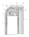
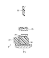
- FIG. 5 is an enlarged cross-sectional view taken along a line II in FIG. BRIEF DESCRIPTION OF THE DRAWINGS
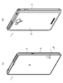
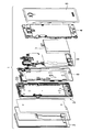
- the mobile telephone which concerns on Embodiment 1 of this invention is shown, (a) is the perspective view seen from the front, (b) is the perspective view seen from the back. It is a disassembled perspective view which shows a mobile telephone.
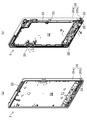
- FIG. 2A is a perspective view of the housing, viewed from the front
- FIG. FIG. 5 is a view corresponding to FIG. 4 with a resin portion removed, where (a) is a perspective view seen from the front, and (b) is a perspective view seen from the back.
- FIG. 6 is a view corresponding to FIG.
- the mobile phone 1 includes, for example, a housing 3 in which a display unit 2 is housed on the front side, and the back thereof. Is covered with a back side cabinet 4 and the back side is covered with a flat rear plate 5.
- a main substrate 6, a rechargeable battery 7, a waterproof packing 8 and the like are accommodated between the back surface of the housing 3 and the front surface of the rear plate 5.
- the side wall end 31 ′′ a of the cylindrical metal sheet 31 ′′ is cut.
- a metal sheet 31 ′′ ′′ is formed in a rectangular ring shape as shown in FIG.
- a slit 31 '' 'a is provided at the boundary between the outer wall portion 31a and the antenna portion 31b.
- necessary through holes are also provided.
- both ends in the thickness direction of the ring-shaped metal sheet 31 ′′ ′′ are cut into a ring shape.
- the antenna portion 31b is electrically divided by a resin material made of an insulating material.
- the antenna part 31b and the outer wall part 31a are connected by the resin part 33, the required strength is ensured.
- the antenna portion 31b can be electrically joined to the main board 6 via the contact part 34 while being electrically insulated from the outer wall portion 31a and the reinforcing sheet metal 32.
- the antenna member can be easily manufactured as compared with a component composed of a plurality of components that constitute the antenna member as a separate component, and the strength can be ensured while reducing the necessary space.
- the metal frame main body 31 can be formed from a single metal sheet 31 'by pressing or the like, machining time and cost are greatly reduced compared to machining from a metal block.
- the metal part of the housing 3 is composed of a plurality of members (metal frame main body 31, reinforcing sheet metal 32, and contact part 34). The degree becomes higher. Further, it is not necessary to provide a protrusion or the like by cutting out from a thick metal plate, the processing cost is greatly reduced, and unnecessary portions can be easily omitted, and the housing 3 is lightened.
- the sensitive antenna portion 31b can be provided by a simple and inexpensive method.
- (Embodiment 2) 10 to 15 show a second embodiment of the present invention, which differs from the first embodiment mainly in that the shape of the metal frame main body 131 is different.
- the same portions as those in FIGS. 1 to 9 are denoted by the same reference numerals, and detailed description thereof is omitted.
- the metal frame main body 131 has a bottom plate 131c unlike the first embodiment. For this reason, in the edge part cutting process after a press process, although the baseplate 131c is not cut off, the lower side wall is cut off. This lower part is covered with a resin part 133.
- the rigidity of the metal frame main body 131 is as high as the bottom plate 131c is present, and it is easy to dissipate the internal heat, but the mass is increased accordingly.
- a housing mounting nut 135 is joined to the antenna portion 131b by, for example, spot welding. Since the joint portion 136 is completely covered with the resin portion 133, the joint portion 136 is reinforced and does not deteriorate due to contact with air. The casing mounting nut 135 is exposed at a portion other than the joint 136.
- the antenna 131b can be used as an antenna by being connected to a main board (not shown).
- the resin portion 133 is formed with a continuous flat surface 133a as a mating surface, and a waterproof packing (not shown) comes into contact therewith.
- a contact part 134 is joined to the bottom plate 131c.
- a part of the joining part 136 is covered with the resin part 133, but a part is exposed.
- the casing 103 is reinforced by embedding a reinforcing plate 137 having an L-shaped cross section under the casing 103.
- a reinforcing plate 137 having an L-shaped cross section under the casing 103.
- the entire reinforcing plate 137 including the joint 136 is covered.
- the joining portion 136 is covered with the resin portion 133, but a part of the reinforcing plate 137 is exposed.
- the cellular phone 1 it is possible to obtain an inexpensive, lightweight, and highly rigid housing 3 that uses a metal for a necessary portion.
- the present invention may be configured as follows with respect to the above embodiment.
- the shape is not particularly limited, and may be a rectangular frame shape, a circular dish shape, an elliptical dish shape, or the like.
Landscapes
- Engineering & Computer Science (AREA)
- Signal Processing (AREA)
- Manufacturing & Machinery (AREA)
- Mechanical Engineering (AREA)
- Telephone Set Structure (AREA)
Abstract
少なくとも一部が外観に現れる金属フレーム本体(31)に少なくとも1つの金属部材(補強板金(32)、接点部品)を接合した状態でインサート成形により、樹脂部(33)を設ける。これにより、必要な部分に金属を使用した安価で軽量かつ剛性の高い筐体を得る。
Description
本発明は、電子機器及びその筐体の製造方法に関するものである。
従来より、例えば、特許文献1のように、加工された金属製の金属フレームと、金属フレームの表面に被覆され、表面に付着された熱硬化性合成樹脂を含むコーティング材と、コーティング材の上面に一体に熱融着により成形されもので、かつ熱可塑性合成樹脂製で金属フレームと共に電子機器筐体の形状、構造を形成するための構造部とからなる電子機器筐体は知られている。この筐体では、樹脂部で必要となる凹凸のある形状を実現している。
しかしながら、従来の電子機器では、金属フレームに樹脂製の凹凸のあるリブ等をインサート成形することはできるが、リブなどの突出部分を金属製のものとする場合、金属部材の削り出しや金属成形品を用いる必要がある。金属板を用いる場合、削り出しなどの機械加工の費用を必要としないが、リブなどの凹凸のある複雑な形状とすることができない。
本発明は、かかる点に鑑みてなされたものであり、その目的とするところは、必要な部分に金属を使用した安価で軽量かつ剛性の高い筐体を得ることにある。
上記の目的を達成するために、この発明では、少なくとも一部が外観に現れる金属フレーム本体と金属部材とを接続したものをインサート成形するようにした。
具体的には、本発明では、金属フレーム本体を有する筐体を備えた電子機器を前提とし、上記筐体は、上記金属フレーム本体に少なくとも1つの金属部材を接合した状態で該金属フレーム本体と該金属部材との接合部の少なくとも一部が樹脂材料で覆われた樹脂成形品よりなるものとする。
上記の構成によると、筐体の金属で構成される部分を複数の金属部材で構成するので、1つの金属成形品で構成するものに比べ、最適な材質、厚さ等の金属を使用でき、設計自由度が高くなる。また、厚い金属板から削り出しによって突起などを設ける必要がなく、加工費が大幅に削減されると共に、不要な部分を省きやすくなって筐体が軽くなる。また、筐体内部で発生した熱を金属部材を介して金属フレーム本体に伝達し放熱することができる。さらに金属フレーム本体と金属部材との接合部の少なくとも一部を樹脂材料で覆っているので、接合部が外れにくく強度が高い。
また、本発明では、金属フレーム本体を有する電子機器の筐体の製造方法を前提とし、この製造方法は、
1枚の金属シートを筒状に絞るプレス工程と、
上記筒状の金属シートの側壁端部を切断する端部切断工程と、
上記側壁端部を切断した金属シートから形成した金属フレーム本体に少なくとも1つの金属部材を接合する接合工程と、
上記金属部材が接合された金属フレーム本体を射出成形型に載置した状態で溶融樹脂を射出し、上記金属フレーム本体と上記金属部材との接合部の少なくとも一部を樹脂材料で覆うインサート成形工程とを含む構成とする。
1枚の金属シートを筒状に絞るプレス工程と、
上記筒状の金属シートの側壁端部を切断する端部切断工程と、
上記側壁端部を切断した金属シートから形成した金属フレーム本体に少なくとも1つの金属部材を接合する接合工程と、
上記金属部材が接合された金属フレーム本体を射出成形型に載置した状態で溶融樹脂を射出し、上記金属フレーム本体と上記金属部材との接合部の少なくとも一部を樹脂材料で覆うインサート成形工程とを含む構成とする。
上記の構成によると、一枚のシートから金属フレーム本体をプレス加工等により成形できるので、金属ブロックからの削り出しに比べ、最適な材質、厚さ等の金属を使用でき、機械加工の時間及び費用が大幅に低減される。また、筐体の金属で構成される部分を複数の金属部材で構成するので、1つの金属成形品で構成するものに比べ、設計自由度が高くなると共に、不要な部分を省きやすくなって筐体が軽くなる。また、筐体内部で発生した熱を金属部材を介して金属フレーム本体に伝達し放熱することができる。さらに金属フレーム本体と金属部材との接合部の少なくとも一部を樹脂材料で覆っているので、接合部が外れにくく強度が高い。
以上説明したように、本発明によれば、筐体を金属フレーム本体に少なくとも1つの金属部材を接合した状態でインサート成形された樹脂成形品で構成したので、必要な部分に金属を使用した安価で軽量かつ剛性の高い筐体を得ることができる。
以下、本発明の実施形態を図面に基づいて説明する。
(実施形態1)
図2及び図3は、本発明の実施形態1の電子機器としての携帯電話機1を示し、この携帯電話機1は、例えば、正面側に表示部2が収容された筐体3を備え、その背後が背面側キャビネット4で覆われ、その背面が平板状のリアプレート5で覆われている。筐体3の背面とリアプレート5の正面との間には、例えばメイン基板6、充電池7、防水パッキン8等が収容されている。
図2及び図3は、本発明の実施形態1の電子機器としての携帯電話機1を示し、この携帯電話機1は、例えば、正面側に表示部2が収容された筐体3を備え、その背後が背面側キャビネット4で覆われ、その背面が平板状のリアプレート5で覆われている。筐体3の背面とリアプレート5の正面との間には、例えばメイン基板6、充電池7、防水パッキン8等が収容されている。
図4~図6に示すように、本実施形態の筐体3は、矩形枠状の金属フレーム本体31と、矩形板状の金属部材としての補強板金32等がインサート成形されて枠状の樹脂部33が一体成形されている。金属フレーム本体31は、外壁部31aとその下側の樹脂部33で分断されたアンテナ部31bとを有する。アンテナ部31bを電気的に分断するため、樹脂部33は、絶縁材よりなる。外壁部31aには、補強板金32の周縁に垂直に折り曲げられた折曲部32aがスポット溶接により接合されている。図8にも示すように、アンテナ部31bには、金属部材としての接点部品34が同様に接合されている。本実施形態では、板厚が薄くてよい補強板金32よりも接点部品34の板厚が大きくなっている。これらの接合方法は、接着、嵌め込み等でもよい。金属フレーム本体31、補強板金32及び接点部品34の材質は特に限定されず、アルミニウム合金、ステンレス鋼板等よりなる。なお、図8に示す金属製ナット35は、金属フレーム本体31には接合されてはおらず、インサート成形時又はその後に取り付けられる。
図1及び図7に示すように、金属フレーム本体31の内側周縁は矩形枠状に樹脂部33で覆われており、背面側キャビネット4との間で密閉性を保つために挟み込む防水パッキン8が当接するほぼ連続した合わせ面としての平坦面33aが形成されている。平坦面33aは、防水パッキン8が当たる場合だけでなく、両面テープや接着材によって接着が行われる場合もある。このように、筐体3が金属フレーム本体31と補強板金32及び接点部品34とを含むような構成でも、インサート成形される樹脂部33であれば連続した平坦面33aを有する複雑な形状でも形成しやすく、筐体3に高い防水性能を発揮させることができる。
-筐体の製造方法-
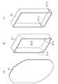
次に、本実施形態に係る筐体3の製造方法について簡単に説明する。まず、アルミニウム合金などよりなる1枚の金属シート31’を用意し、外形カット工程において、図9(a)に示すように適切な形状にカットする。
次に、本実施形態に係る筐体3の製造方法について簡単に説明する。まず、アルミニウム合金などよりなる1枚の金属シート31’を用意し、外形カット工程において、図9(a)に示すように適切な形状にカットする。
次いで、プレス工程において、例えばプレス機械を用いて図9(b)に示すように筒状の金属シート31’’に成形する。
次いで、端部切断工程において、筒状の金属シート31’’の側壁端部31’’aを切断する。このとき、底板31’’bも切断することにより、図9(c)に示すように、矩形のリング状に金属シート31’’’が成形される。そして、例えば外壁部31aとアンテナ部31bとの境界にスリット31’’’aを設けておく。このスリット31’’’a以外は、特に図示しないが、必要な貫通孔等も設けておく。
次いで、接合工程において、リング状の金属シート31’’’に複数の金属部材をスポット溶接等により接合する。具体的には、外壁部31aに補強板金32の折曲部32aをスポット溶接し、アンテナ部31bとなる、スリット31’’’aよりも下側部分には、複数の接点部品34をスポット溶接する。スポット溶接であれば、熱変形などの悪影響を受けにくい。
次いで、インサート成形工程において、補強板金32及び接点部品34が接合された金属フレーム本体31を射出成形型に載置した状態で溶融樹脂を射出する。このとき、少なくとも外壁部31aと補強板金32の接合部36及びアンテナ部31bと接点部品34の接合部36の全体をそれぞれ樹脂材料で覆う。このようにすれば、スポット溶接のように比較的強度の弱い接合であっても、樹脂部33で覆うことで、強度が向上する上に接合部36が空気に触れて劣化することがない。
次いで、インサート成形後にリング状の金属シート31’’’の厚さ方向両端部をカットしてリング状に切断する。このとき、スリット31’’’aの厚さ方向両端部も切断することで、アンテナ部31bが絶縁材よりなる樹脂材料で電気的に分断される。また、アンテナ部31bと外壁部31aとは樹脂部33で連結されているので、必要な強度は確保されている。このことで、アンテナ部31bは、電気的に外壁部31a及び補強板金32と絶縁されながら、接点部品34を介してメイン基板6と電気的に接合可能となる。このようにすれば、アンテナ部材を別部品として構成する複数部品からなるものに比べて製造が容易であり、また必要なスペースを小さくしながら、強度も確保することができる。
このように、一枚の金属シート31’から金属フレーム本体31をプレス加工等により成形できるので、金属ブロックからの削り出しに比べ、機械加工の時間及び費用が大幅に低減される。
また、筐体3の金属で構成される部分を複数の部材(金属フレーム本体31、補強板金32及び接点部品34)で構成するので、最適な材質、厚さ等の金属を使用でき、設計自由度が高くなる。また、厚い金属板から削り出しによって突起などを設ける必要がなく、加工費が大幅に削減されると共に、不要な部分を省きやすくなって筐体3が軽くなる。
本実施形態では、金属フレーム本体31と補強板金32及び接点部品34との接合部36の全体を樹脂材料で覆ったので、補強板金32及び接点部品34が金属フレーム本体31から外れるのが防止され、剛性も向上する。また樹脂で覆われた溶接部分は空気に触れないので、劣化しにくい。
また、本実施形態では、リング形状の金属フレーム本体31(外壁部31a)の内周面に平板状の補強板金32を接続したので、筐体3の内部でメイン基板6や充電池7において発生した熱を補強板金32からリング形状の金属フレーム本体31に伝達させて効果的に外部に放熱させることができる。
また、本実施形態では、リング形状の金属フレーム本体31の一部が樹脂部33によって分離されてアンテナ部31bを構成し、そのアンテナ部31bに接点部品34を接合した上でインサート成形するようにしたので、感度のよいアンテナ部31bを簡単かつ安価な方法で設けることができる。
したがって、本実施形態に係る携帯電話機1によると、必要な部分に金属を使用した安価で軽量かつ剛性の高い筐体3を得ることができる。
(実施形態2)
図10~図15は、本発明の実施形態2を示し、主に金属フレーム本体131の形状が異なる点で上記実施形態1と異なる。なお、本実施形態では、図1~図9と同じ部分については同じ符号を付してその詳細な説明は省略する。
図10~図15は、本発明の実施形態2を示し、主に金属フレーム本体131の形状が異なる点で上記実施形態1と異なる。なお、本実施形態では、図1~図9と同じ部分については同じ符号を付してその詳細な説明は省略する。
本実施形態では、金属フレーム本体131は、上記実施形態1と異なり、底板131cを有する。このため、プレス工程後の端部切断工程において、底板131cは切り離さないが、下側の側壁が切り離されている。この下側部分は、樹脂部133で覆われている。底板131cがある分だけ金属フレーム本体131の剛性は高く、内部の熱を放熱しやすくなっているが、その分だけ質量は重くなっている。
図11に示すように、筐体取付用ナット135がアンテナ部131bに例えばスポット溶接等により、接合されている。この接合部136は、樹脂部133で完全に覆われているので、接合部136が補強されると共に、空気に触れて劣化することはない。筐体取付用ナット135は接合部136以外の部分は露出しており、例えば、図示しないメイン基板に接続することで、アンテナ部131bをアンテナとして使用できる。本実施形態においても、樹脂部133には、連続した、合わせ面としての平坦面133aが形成されており、図示しない防水パッキンが当接するようになっている。
また図12に示すように、底板131cには、接点部品134が接合されている。この断面では、接合部136の一部が樹脂部133で覆われているが、一部は露出している。この弾性を有する接点部品134に図示しないメイン基板が接続されることで、グランドを取ったり、底板131cをアンテナとして使用したりすることができる。
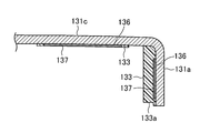
また図13及び図14に示すように、筐体103の下側には、断面L字状の補強板137を埋設させることで、筐体103の補強が行われている。外壁部131a側では、接合部136を含め補強板137の全体が覆われている。底板131c側では、接合部136が樹脂部133で覆われているが、補強板137の一部は露出している。
したがって、本実施形態に係る携帯電話機1においても、必要な部分に金属を使用した安価で軽量かつ剛性の高い筐体3を得ることができる。
(その他の実施形態)
本発明は、上記実施形態について、以下のような構成としてもよい。
本発明は、上記実施形態について、以下のような構成としてもよい。
すなわち、上記実施形態では、矩形皿状の筐体3について説明したが、その形状は特に限定されず、矩形枠状、円形皿状、楕円皿状等でもよい。
上記実施形態では、電子機器は、携帯電話機1としたが、タブレット端末、PHS(Personal Handy-phone System )、PDA(Personal Digital Assistant)、パソコン、モバイルツール、電子辞書、電卓、ゲーム機等であってもよく、特に小型の液晶ディスプレイ、液晶テレビ、ブルーレイディスクレコーダ、DVDレコーダ等であってもよい。
なお、以上の実施形態は、本質的に好ましい例示であって、本発明、その適用物や用途の範囲を制限することを意図するものではない。また、各実施形態に記載された技術的特徴は、互いに組合せ可能であり、組み合わせることにより、新しい技術的特徴を形成することができる。
1 携帯電話機(電子機器)
2 表示部
3 筐体
4 背面側キャビネット
5 リアプレート
6 メイン基板
7 充電池
8 防水パッキン
31 金属フレーム本体
31a 外壁部
31b アンテナ部
32 補強板金(金属部材)
32a 折曲部
33 樹脂部
33a 平坦面(合わせ面)
34 接点部品(金属部材)
35 金属製ナット
36 接合部
31’ 1枚の金属シート
31’’ 筒状の金属シート
31’’b 底板
31’’a 側壁端部
31’’’ リング状の金属シート
31’’’a スリット
103 筐体
131 金属フレーム本体
131a 外壁部
131b アンテナ部
131c 底板
133 樹脂部
133a 平坦面(合わせ面)
134 接点部品
135 筐体取付用ナット
136 接合部
137 補強板
2 表示部
3 筐体
4 背面側キャビネット
5 リアプレート
6 メイン基板
7 充電池
8 防水パッキン
31 金属フレーム本体
31a 外壁部
31b アンテナ部
32 補強板金(金属部材)
32a 折曲部
33 樹脂部
33a 平坦面(合わせ面)
34 接点部品(金属部材)
35 金属製ナット
36 接合部
31’ 1枚の金属シート
31’’ 筒状の金属シート
31’’b 底板
31’’a 側壁端部
31’’’ リング状の金属シート
31’’’a スリット
103 筐体
131 金属フレーム本体
131a 外壁部
131b アンテナ部
131c 底板
133 樹脂部
133a 平坦面(合わせ面)
134 接点部品
135 筐体取付用ナット
136 接合部
137 補強板
Claims (7)
- 少なくとも一部が外観に現れる金属フレーム本体を有する筐体を備えた電子機器において、
上記筐体は、上記金属フレーム本体に少なくとも1つの金属部材を接合した状態で該金属フレーム本体と該金属部材との接合部の少なくとも一部が樹脂材料で覆われた樹脂成形品よりなる
ことを特徴とする電子機器。 - 請求項1に記載の電子機器において、
上記金属フレーム本体と上記金属部材との接合部の全体が樹脂材料で覆われている
ことを特徴とする電子機器。 - 請求項1又は2に記載の電子機器において、
上記金属フレーム本体の周縁は、樹脂材料で覆われ、他の部品との合わせ面となる平坦面を有する
ことを特徴とする電子機器。 - 請求項1から3のいずれか1つに記載の電子機器において、
上記金属フレーム本体は、リング形状であり、
上記金属部材は、上記リング形状の金属フレーム本体の内周面に接続された平板状の補強板金である
ことを特徴とする電子機器。 - 請求項4に記載の電子機器において、
上記リング形状の金属フレーム本体の一部は上記樹脂材料によって分離されてアンテナ部を構成し、
上記金属部材は、上記アンテナ部に接続される接点部品である
ことを特徴とする電子機器。 - 金属フレーム本体を有する電子機器の筐体の製造方法において、
1枚の金属シートを筒状に絞るプレス工程と、
上記筒状の金属シートの側壁端部を切断する端部切断工程と、
上記側壁端部を切断した金属シートから形成した金属フレーム本体に少なくとも1つの金属部材を接合する接合工程と、
上記金属部材が接合された金属フレーム本体を金型に載置した状態で溶融樹脂を注入し、上記金属フレーム本体と上記金属部材との接合部の少なくとも一部を樹脂材料で覆うインサート成形工程とを含む
ことを特徴とする電子機器の筐体の製造方法。 - 請求項6に記載の電子機器の筐体の製造方法において、
上記インサート成形工程の後に上記金属フレーム本体をリング状に切断し、一部をアンテナ部として上記樹脂材料で分断する工程とを含み、
上記アンテナ部は、上記金属部材としての接点部品が接合されている
ことを特徴とする電子機器の筐体の製造方法。
Applications Claiming Priority (2)
| Application Number | Priority Date | Filing Date | Title |
|---|---|---|---|
| JP2014086436 | 2014-04-18 | ||
| JP2014-086436 | 2014-04-18 |
Publications (1)
| Publication Number | Publication Date |
|---|---|
| WO2015159518A1 true WO2015159518A1 (ja) | 2015-10-22 |
Family
ID=54323742
Family Applications (1)
| Application Number | Title | Priority Date | Filing Date |
|---|---|---|---|
| PCT/JP2015/001998 Ceased WO2015159518A1 (ja) | 2014-04-18 | 2015-04-09 | 電子機器及びその筐体の製造方法 |
Country Status (1)
| Country | Link |
|---|---|
| WO (1) | WO2015159518A1 (ja) |
Cited By (3)
| Publication number | Priority date | Publication date | Assignee | Title |
|---|---|---|---|---|
| CN108882579A (zh) * | 2018-06-29 | 2018-11-23 | Oppo广东移动通信有限公司 | 中框组件及电子装置 |
| CN108882580A (zh) * | 2018-06-30 | 2018-11-23 | Oppo广东移动通信有限公司 | 壳体、电子设备及壳体制作方法 |
| JP2020191124A (ja) * | 2016-09-22 | 2020-11-26 | アップル インコーポレイテッドApple Inc. | ディスプレイモジュール及びアンダーカットプラスチックフレームをもつガラス |
Citations (5)
| Publication number | Priority date | Publication date | Assignee | Title |
|---|---|---|---|---|
| JPH0839603A (ja) * | 1994-07-29 | 1996-02-13 | Matsushita Electric Ind Co Ltd | インサート部品の成形方法 |
| JP2004050488A (ja) * | 2002-07-17 | 2004-02-19 | Taisei Plas Co Ltd | アルミニューム合金と樹脂の複合体とその製造方法 |
| JP2007176108A (ja) * | 2005-12-28 | 2007-07-12 | Sharp Corp | 電子機器のキャビネットをインサート成形する方法及び皮革製カバーによって覆われたキャビネットを有する電子機器 |
| US20100215938A1 (en) * | 2009-02-20 | 2010-08-26 | Taiwan Green Point Enterprises Co., Ltd. | Method of selective plastic insert molding on metal component |
| JP2014029918A (ja) * | 2012-07-31 | 2014-02-13 | Sharp Corp | 携帯端末 |
-
2015
- 2015-04-09 WO PCT/JP2015/001998 patent/WO2015159518A1/ja not_active Ceased
Patent Citations (5)
| Publication number | Priority date | Publication date | Assignee | Title |
|---|---|---|---|---|
| JPH0839603A (ja) * | 1994-07-29 | 1996-02-13 | Matsushita Electric Ind Co Ltd | インサート部品の成形方法 |
| JP2004050488A (ja) * | 2002-07-17 | 2004-02-19 | Taisei Plas Co Ltd | アルミニューム合金と樹脂の複合体とその製造方法 |
| JP2007176108A (ja) * | 2005-12-28 | 2007-07-12 | Sharp Corp | 電子機器のキャビネットをインサート成形する方法及び皮革製カバーによって覆われたキャビネットを有する電子機器 |
| US20100215938A1 (en) * | 2009-02-20 | 2010-08-26 | Taiwan Green Point Enterprises Co., Ltd. | Method of selective plastic insert molding on metal component |
| JP2014029918A (ja) * | 2012-07-31 | 2014-02-13 | Sharp Corp | 携帯端末 |
Cited By (3)
| Publication number | Priority date | Publication date | Assignee | Title |
|---|---|---|---|---|
| JP2020191124A (ja) * | 2016-09-22 | 2020-11-26 | アップル インコーポレイテッドApple Inc. | ディスプレイモジュール及びアンダーカットプラスチックフレームをもつガラス |
| CN108882579A (zh) * | 2018-06-29 | 2018-11-23 | Oppo广东移动通信有限公司 | 中框组件及电子装置 |
| CN108882580A (zh) * | 2018-06-30 | 2018-11-23 | Oppo广东移动通信有限公司 | 壳体、电子设备及壳体制作方法 |
Similar Documents
| Publication | Publication Date | Title |
|---|---|---|
| KR102866538B1 (ko) | 디바이스 인클로저 | |
| US8338703B2 (en) | Housing for an electronic device, device comprising such a housing and method for manufacturing such a housing | |
| US9001002B2 (en) | Portable electronic device housing having insert molding around antenna | |
| KR101748344B1 (ko) | 스피커 모듈 | |
| KR101819734B1 (ko) | 스피커모듈 사운드홀 차폐부재와 그 장착방법 및 스피커모듈 | |
| EP2632171B1 (en) | Loudspeaker housing and mobile terminal device | |
| US10088873B2 (en) | Chassis structure for portable electronic devices | |
| US20120033357A1 (en) | Electronic device housing and manufacturing method thereof | |
| US20240284624A1 (en) | Core shell with various filler materials for enhanced thermal conductivity | |
| KR101431566B1 (ko) | 베젤 내부에 부품 실장이 가능한 지문인식 모듈 제조방법 및 그 지문인식 모듈 | |
| WO2015159518A1 (ja) | 電子機器及びその筐体の製造方法 | |
| CN106295589A (zh) | 指纹模组和具有其的终端设备、及该指纹模组的加工方法 | |
| US10869147B2 (en) | Sound device and assembling method therefor | |
| US8437131B2 (en) | Electronic device housing and manufacturing method thereof | |
| JP2014057165A (ja) | 防水携帯端末 | |
| CN206100435U (zh) | 一种扬声器模组壳体、扬声器模组及发声装置 | |
| US20180184184A1 (en) | Loudspeaker module | |
| CN107222817B (zh) | 扬声器模组外壳以及扬声器模组 | |
| CN206180108U (zh) | 壳体、天线装置及移动终端 | |
| KR101421487B1 (ko) | 필름이 적용된 인몰드 안테나 및 그 제작 방법 | |
| WO2019105294A1 (zh) | 中框组件、电子设备及中框组件的制造方法 | |
| JP2015050675A (ja) | 携帯端末及びその製造方法 | |
| KR20140045641A (ko) | 이동단말기 및 이동 단말기 내부 프레임의 제조 방법 | |
| JP2013008844A (ja) | 筐体および該筐体を備えた携帯電子機器、並びに該筐体の製造方法 | |
| JP2015088873A (ja) | 基板支持ケース及び基板付ケース |
Legal Events
| Date | Code | Title | Description |
|---|---|---|---|
| 121 | Ep: the epo has been informed by wipo that ep was designated in this application |
Ref document number: 15779363 Country of ref document: EP Kind code of ref document: A1 |
|
| NENP | Non-entry into the national phase |
Ref country code: DE |
|
| NENP | Non-entry into the national phase |
Ref country code: JP |
|
| 122 | Ep: pct application non-entry in european phase |
Ref document number: 15779363 Country of ref document: EP Kind code of ref document: A1 |