WO2015156200A1 - Turbine ventilation structure - Google Patents
Turbine ventilation structure Download PDFInfo
- Publication number
- WO2015156200A1 WO2015156200A1 PCT/JP2015/060461 JP2015060461W WO2015156200A1 WO 2015156200 A1 WO2015156200 A1 WO 2015156200A1 JP 2015060461 W JP2015060461 W JP 2015060461W WO 2015156200 A1 WO2015156200 A1 WO 2015156200A1
- Authority
- WO
- WIPO (PCT)
- Prior art keywords
- strut
- exhaust
- turbine
- strut cover
- housing
- Prior art date
Links
Images


Classifications
-
- F—MECHANICAL ENGINEERING; LIGHTING; HEATING; WEAPONS; BLASTING
- F01—MACHINES OR ENGINES IN GENERAL; ENGINE PLANTS IN GENERAL; STEAM ENGINES
- F01D—NON-POSITIVE DISPLACEMENT MACHINES OR ENGINES, e.g. STEAM TURBINES
- F01D25/00—Component parts, details, or accessories, not provided for in, or of interest apart from, other groups
- F01D25/30—Exhaust heads, chambers, or the like
-
- F—MECHANICAL ENGINEERING; LIGHTING; HEATING; WEAPONS; BLASTING
- F01—MACHINES OR ENGINES IN GENERAL; ENGINE PLANTS IN GENERAL; STEAM ENGINES
- F01D—NON-POSITIVE DISPLACEMENT MACHINES OR ENGINES, e.g. STEAM TURBINES
- F01D25/00—Component parts, details, or accessories, not provided for in, or of interest apart from, other groups
- F01D25/08—Cooling; Heating; Heat-insulation
- F01D25/12—Cooling
- F01D25/125—Cooling of bearings
-
- F—MECHANICAL ENGINEERING; LIGHTING; HEATING; WEAPONS; BLASTING
- F01—MACHINES OR ENGINES IN GENERAL; ENGINE PLANTS IN GENERAL; STEAM ENGINES
- F01D—NON-POSITIVE DISPLACEMENT MACHINES OR ENGINES, e.g. STEAM TURBINES
- F01D25/00—Component parts, details, or accessories, not provided for in, or of interest apart from, other groups
- F01D25/16—Arrangement of bearings; Supporting or mounting bearings in casings
- F01D25/162—Bearing supports
-
- F—MECHANICAL ENGINEERING; LIGHTING; HEATING; WEAPONS; BLASTING
- F01—MACHINES OR ENGINES IN GENERAL; ENGINE PLANTS IN GENERAL; STEAM ENGINES
- F01D—NON-POSITIVE DISPLACEMENT MACHINES OR ENGINES, e.g. STEAM TURBINES
- F01D25/00—Component parts, details, or accessories, not provided for in, or of interest apart from, other groups
- F01D25/24—Casings; Casing parts, e.g. diaphragms, casing fastenings
-
- F—MECHANICAL ENGINEERING; LIGHTING; HEATING; WEAPONS; BLASTING
- F01—MACHINES OR ENGINES IN GENERAL; ENGINE PLANTS IN GENERAL; STEAM ENGINES
- F01D—NON-POSITIVE DISPLACEMENT MACHINES OR ENGINES, e.g. STEAM TURBINES
- F01D9/00—Stators
- F01D9/02—Nozzles; Nozzle boxes; Stator blades; Guide conduits, e.g. individual nozzles
-
- F—MECHANICAL ENGINEERING; LIGHTING; HEATING; WEAPONS; BLASTING
- F01—MACHINES OR ENGINES IN GENERAL; ENGINE PLANTS IN GENERAL; STEAM ENGINES
- F01D—NON-POSITIVE DISPLACEMENT MACHINES OR ENGINES, e.g. STEAM TURBINES
- F01D9/00—Stators
- F01D9/06—Fluid supply conduits to nozzles or the like
- F01D9/065—Fluid supply or removal conduits traversing the working fluid flow, e.g. for lubrication-, cooling-, or sealing fluids
-
- F—MECHANICAL ENGINEERING; LIGHTING; HEATING; WEAPONS; BLASTING
- F02—COMBUSTION ENGINES; HOT-GAS OR COMBUSTION-PRODUCT ENGINE PLANTS
- F02C—GAS-TURBINE PLANTS; AIR INTAKES FOR JET-PROPULSION PLANTS; CONTROLLING FUEL SUPPLY IN AIR-BREATHING JET-PROPULSION PLANTS
- F02C7/00—Features, components parts, details or accessories, not provided for in, or of interest apart form groups F02C1/00 - F02C6/00; Air intakes for jet-propulsion plants
- F02C7/04—Air intakes for gas-turbine plants or jet-propulsion plants
-
- F—MECHANICAL ENGINEERING; LIGHTING; HEATING; WEAPONS; BLASTING
- F05—INDEXING SCHEMES RELATING TO ENGINES OR PUMPS IN VARIOUS SUBCLASSES OF CLASSES F01-F04
- F05D—INDEXING SCHEME FOR ASPECTS RELATING TO NON-POSITIVE-DISPLACEMENT MACHINES OR ENGINES, GAS-TURBINES OR JET-PROPULSION PLANTS
- F05D2220/00—Application
- F05D2220/30—Application in turbines
- F05D2220/32—Application in turbines in gas turbines
-
- F—MECHANICAL ENGINEERING; LIGHTING; HEATING; WEAPONS; BLASTING
- F05—INDEXING SCHEMES RELATING TO ENGINES OR PUMPS IN VARIOUS SUBCLASSES OF CLASSES F01-F04
- F05D—INDEXING SCHEME FOR ASPECTS RELATING TO NON-POSITIVE-DISPLACEMENT MACHINES OR ENGINES, GAS-TURBINES OR JET-PROPULSION PLANTS
- F05D2240/00—Components
- F05D2240/10—Stators
- F05D2240/12—Fluid guiding means, e.g. vanes
- F05D2240/122—Fluid guiding means, e.g. vanes related to the trailing edge of a stator vane
-
- F—MECHANICAL ENGINEERING; LIGHTING; HEATING; WEAPONS; BLASTING
- F05—INDEXING SCHEMES RELATING TO ENGINES OR PUMPS IN VARIOUS SUBCLASSES OF CLASSES F01-F04
- F05D—INDEXING SCHEME FOR ASPECTS RELATING TO NON-POSITIVE-DISPLACEMENT MACHINES OR ENGINES, GAS-TURBINES OR JET-PROPULSION PLANTS
- F05D2260/00—Function
- F05D2260/20—Heat transfer, e.g. cooling
- F05D2260/205—Cooling fluid recirculation, i.e. after cooling one or more components is the cooling fluid recovered and used elsewhere for other purposes
-
- F—MECHANICAL ENGINEERING; LIGHTING; HEATING; WEAPONS; BLASTING
- F05—INDEXING SCHEMES RELATING TO ENGINES OR PUMPS IN VARIOUS SUBCLASSES OF CLASSES F01-F04
- F05D—INDEXING SCHEME FOR ASPECTS RELATING TO NON-POSITIVE-DISPLACEMENT MACHINES OR ENGINES, GAS-TURBINES OR JET-PROPULSION PLANTS
- F05D2260/00—Function
- F05D2260/60—Fluid transfer
- F05D2260/608—Aeration, ventilation, dehumidification or moisture removal of closed spaces
Definitions
- the present invention mainly relates to a turbine ventilation structure of a gas turbine engine including an exhaust diffuser having a sheet metal double structure.
- an exhaust diffuser for discharging exhaust gas from a turbine in a gas turbine engine As a structure of an exhaust diffuser for discharging exhaust gas from a turbine in a gas turbine engine, a double structure including a sheet metal outer cylinder and an inner cylinder is generally employed (for example, Patent Document 1).
- appropriate ventilation is required to thermally protect members formed by casting, such as a support structure material inside the diffuser and a bearing box. Is done.
- ventilation can be performed by sucking ventilation air into the exhaust diffuser using the negative pressure.
- the exhaust in the exhaust diffuser becomes a swirling flow and collides with the strut in an oblique direction.
- the exhaust flow is disturbed in the vicinity of the strut, and as a result, a sufficient negative pressure cannot be obtained in the exhaust diffuser.
- the exhaust air from the turbine is separated from the inner wall of the exhaust diffuser due to the ventilation air flowing along the inner wall of the exhaust diffuser, and the exhaust diffuser performance is improved. descend.
- the object of the present invention is to solve the above-mentioned problems by providing a sufficient negative pressure for ventilation in the exhaust diffuser without degrading the performance of the exhaust diffuser in all operating conditions (load conditions) of the gas turbine engine. It is an object of the present invention to provide a turbine ventilation structure capable of generating
- a turbine ventilation structure in a gas turbine engine includes an exhaust diffuser that forms an annular exhaust passage through which exhaust gas from a turbine passes between an inner cylinder and an outer cylinder, A strut that supports a bearing inside the inner cylinder across the exhaust diffuser from a radially outer housing of the outer cylinder, a strut cover that is disposed in the exhaust path and covers the outer periphery of the strut, and the exhaust path And a connecting member for connecting the housing and the inner cylinder, the housing introducing air from outside.
- the strut cover has a discharge hole at the rear edge thereof, and further, the middle of the connecting member from the first introduction port.
- the negative pressure in the rear region of the strut cover is reduced by providing the exhaust hole for exhausting ventilation air at the rear edge of the strut cover, which is a structure in the exhaust diffuser, that is, downstream of the exhaust gas flow.
- a plurality of the exhaust holes are provided apart from each other in a direction crossing the exhaust passage in the strut cover. According to this configuration, by providing a plurality of exhaust holes, the distribution of the air flow for ventilation in the exhaust diffuser is made uniform, so that the influence on the exhaust gas flow is suppressed, so that the performance of the exhaust diffuser is reduced. More effectively prevented.
- the strut cover has a flat surface whose rear edge portion faces the downstream side of the exhaust gas, and the cross section of the other portion excluding the rear edge portion is a blade.
- the shape is preferred. According to this configuration, it is possible to more reliably generate the negative pressure behind the strut cover while suppressing the resistance of the strut cover.
- the housing is provided with a second introduction port for introducing air from outside, and the second introduction port is provided between the housing and the outer cylinder. It is preferable to further include a second ventilation passage that passes through the space between the strut and the strut cover and exits from the discharge hole of the strut cover into the exhaust passage.
- the second introduction port is provided separately from the first introduction port, and the second ventilation passage is set separately from the first ventilation passage, thereby cooling the structure around the exhaust diffuser more effectively. can do.
- the second introduction port is provided at an axial position between the turbine outlet in the housing and the strut cover, the portion of the housing that is at a high temperature near the turbine outlet is effectively cooled.
- FIG. 2 is a schematic cross-sectional view taken along line II-II in FIG. It is sectional drawing which expands and shows the peripheral part of an exhaust diffuser of the ventilation structure of FIG.
- FIG. 1 It is a perspective view which shows the strut and strut cover which are used for the ventilation structure of FIG. It is a schematic diagram explaining the effect
- FIG. 1 is a side view in which a part of a gas turbine engine (hereinafter simply referred to as a gas turbine) 1 to which a turbine ventilation structure according to an embodiment of the present invention is applied is broken.
- a gas turbine 1 compresses introduced air IA with a compressor 3 and leads it to a combustor 5, injects fuel F into the combustor 5 and burns it, and uses the obtained high-temperature and high-pressure combustion gas G.
- the turbine 7 is driven.
- a plurality of the combustors 5 are arranged at equal intervals along the circumferential direction of the gas turbine 1.
- the compressor 3 side in the axial direction of the gas turbine 1 may be referred to as “front side” and the turbine 7 side may be referred to as “rear side”.
- an axial flow type compressor is used as the compressor 3.
- the axial flow compressor 3 compresses the air IA sucked from the intake cylinder 15 by a combination of a large number of moving blades 11 and a large number of stationary blades 13.
- the moving blade 11 is disposed on the outer peripheral surface of the front portion of the rotor 17 constituting the rotating portion of the gas turbine 1, and the stationary blade 13 is disposed on the inner peripheral surface of the housing 19.
- Compressed air A compressed by the compressor 3 is supplied to the combustor 5.
- the combustor 5 mixes and combusts the compressed air A supplied from the compressor 3 and the fuel F injected into the combustor 5, and sends a high-temperature and high-pressure combustion gas G to the turbine 7.
- the turbine 7 includes a turbine casing 21 provided inside the housing 19 and covering the rear portion of the rotor 17.
- a plurality of stages of turbine vanes 23 are attached to the inner peripheral portion of the turbine casing 21 at predetermined intervals in the axial direction.
- a plurality of stages of turbine rotor blades 25 are provided at the rear of the rotor 17.
- the turbine stationary blades 23 and the turbine rotor blades 25 are alternately arranged along the axial direction.
- the entire rotor 17 is rotatably supported by the housing 19 via front and rear bearings 27 and 29.
- the rear end of the turbine rotor blade 25 located at the last stage among the multiple stages of turbine rotor blades 25 is a turbine outlet 31.
- An annular exhaust diffuser 33 that exhausts exhaust gas EG from the turbine 7 to the outside is connected to the turbine outlet 31.
- the exhaust diffuser 33 includes an outer cylinder 35 and an inner cylinder 37 that are arranged concentrically with each other, and a first connecting member 41 and a second connecting member 43 that connect the outer cylinder 35 and the inner cylinder 37. .
- the outer cylinder 35 and the inner cylinder 37 are each formed of a sheet metal made of a metal material having excellent heat resistance.
- a space between the outer cylinder 35 and the inner cylinder 37 forms an annular exhaust passage 45 through which the exhaust gas EG passes.
- the outer cylinder 35 is supported by the housing 19.
- a waste heat boiler (not shown) that operates using the heat of the exhaust gas EG is connected to the downstream side of the exhaust diffuser 33.
- FIG. 2 shows a cross-sectional view along the line II-II in Fig. 1.
- FIG. 2 shows a cross section of a portion where the first connecting member 41 and the strut 47 are arranged, but the second connecting member 43 also has the first connecting portion except that no strut is arranged therein. It has the same structure as the member 41.
- the first connecting member 41 (and the second connecting member 43) crosses the exhaust passage 45 in the radial direction.
- a plurality of first connection members 41 (and second connection members 43), for example, six, are provided at equal intervals in the circumferential direction.
- the 1st connection member 41 and the 2nd connection member 43 are each formed with the sheet metal, and have the hollow parts 41a and 43a.
- a strut 47 extending from the housing 19 across the exhaust diffuser 33 is inserted into the hollow portion 41 a of the first connecting member 41.
- the first connecting member 41 forms a strut cover 49 that covers the outer periphery of the strut 47.
- a gap (space) S is formed between the strut 47 and the strut cover 49.
- a ventilation duct 51 is provided at an axial position corresponding to the radially outer side of the second connecting member 43 of the housing 19.
- the ventilation duct 51 forms a first inlet for introducing outside air as ventilation air VA into the gas turbine 1.
- Equipment, for example, a bearing lubricant supply pipe (not shown) is inserted through the hollow portion 43 a of the second connecting member 43.
- the strut 47 is disposed at an axial position substantially corresponding to the rear bearing 29, penetrates the outer cylinder 35 from the radial outer side of the outer cylinder 35 of the exhaust diffuser 33, traverses the exhaust passage 45 in the radial direction, and further the inner cylinder.
- the inner cylinder 37 is penetrated from the radially outer side of 37 and is connected to a bearing support 53 provided on the radially outer side of the rear bearing 29. That is, the strut 47 supports the rear bearing 29 on the housing 19 through the bearing support 53.
- the first connecting member 41, the second connecting member 43, and the strut 47 do not necessarily cross the exhaust passage 45 in the radial direction, and may cross diagonally with respect to the radial direction.
- the strut 47 and the strut cover 49 surrounding the outer periphery thereof are elongated along the axial direction of the gas turbine 1.
- the cut surface of the strut 47 cut by a cylindrical surface concentric with the axial center of the gas turbine 1 is formed into an elongated, substantially rectangular shape, and the strut cover 49 has a substantially blade-shaped cut surface. It is formed into a shape.
- a discharge hole 55 for discharging the air inside the strut cover 49 to the outside is provided in the rear edge portion 49a of the strut cover 49 shown in FIG.
- the “rear edge” of the strut cover 49 refers to the downstream end in the flow direction of the exhaust gas EG (the axial center direction of the gas turbine 1) and the vicinity thereof.
- the strut cover 49 has a flat surface with the rear edge 49a facing the rear side (downstream side of the exhaust gas EG), and the other portions except the rear edge 49a are airfoil in cross section. Is formed. That is, the strut cover 49 has a curved portion 49b having a wing-shaped curved surface that forms a front portion and a side portion, and a flat surface portion 49c having a flat surface that forms a rear portion.
- the discharge hole 55 is provided only in one of the two corner portions 49d corresponding to the boundary between the curved portion 49b and the flat surface portion 49c.
- a plurality of exhaust holes 55 are spaced apart (in this example, in a direction crossing the exhaust passage 45 in the strut cover 49, that is, in the height direction H of the strut cover 49 (in this example, the radial direction of the gas turbine 1). 3) provided.
- a plurality of discharge holes 55 By providing a plurality of discharge holes 55, the distribution of the ventilation air VA flow introduced into the exhaust passage 45 through the first ventilation passage VP1 and the second ventilation passage VP2 described later is made uniform. As a result, since the influence of the ventilation air VA flow on the exhaust gas EG flow is suppressed, the performance degradation of the exhaust diffuser 33 is effectively prevented.
- the position where the discharge hole 55 is provided in the strut cover 49 is not particularly limited as long as it is the rear edge portion 49 a of the strut cover 49.
- it may be provided on the flat surface portion 49c of the strut cover 49, or may be provided in the vicinity of the corner portion 49d of the curved portion 49b.
- the exhaust gas EG flows parallel to the axis of the gas turbine 1 in the full load state shown in FIG. 5A, that is, parallel to the longitudinal direction of the strut cover 49, but in the partial load state including idling, the gas turbine 1 It has a swivel component around one axis. Therefore, in the present embodiment, of the two corner portions 49d of the rear edge portion 49a of the strut cover 49, the corner portion 49d located on the downstream side in the turning direction R of the exhaust gas EG under the idling state of the gas turbine 1 is used. Only the discharge hole 55 is provided. As a result, not only in the full-load operation state shown in FIG. 5A but also in the idling state in FIG.
- the negative pressure is greatest around the strut cover 49.
- the discharge hole 55 is provided in the vicinity of the region D to be formed. Therefore, it is possible to reliably draw the ventilation air VA into the exhaust diffuser 33 in any operating state of the gas turbine 1.
- the range in which the discharge hole 55 is provided in the transverse direction H is the height L of the strut cover 49, that is, the radial direction between the inner peripheral surface of the outer cylinder 35 and the outer peripheral surface of the inner cylinder 37.
- the distance d from both ends in the transverse direction H of the strut cover 49 is preferably 0.1 L or more, and more preferably 0.15 L or more.
- the rear portion may be formed into a curved surface continuous from the curved portion 49b, for example, and the entire cross section of the strut cover 49c may be a complete airfoil.
- the rear portion of the strut cover 49 as the flat surface portion 49c, the negative pressure can be more reliably generated at the rear (downstream side) of the strut cover 49.
- the housing 19 is further provided with a second inlet 61 that penetrates the housing 19, separately from the ventilation duct 51 that is the first inlet. External air is also introduced into the gas turbine 1 as ventilation air VA from the second inlet 61. More specifically, the second introduction port 61 is provided at an axial position in the housing 19 corresponding to the radially outer side of the turbine outlet 31.
- the axial position where the second inlet 61 is provided is not limited to the example shown in the figure, but is preferably provided at an axial position in front of the ventilation duct 51, and the axial position between the turbine outlet 31 and the strut cover 49. More preferably.
- an external pressure is generated through the ventilation duct (first inlet) 51 and the second inlet 61 due to the negative pressure generated in the downstream portion of the discharge hole 55 of the strut cover 49.
- ventilation air VA is introduced as ventilation air VA, and two ventilation passages VP1 and VP2 are formed. That is, the discharge hole of the strut cover 49 passes from the outside of the housing 19 through the hollow portion 43 a of the second connecting member 43, through the space S between the strut 47 and the strut cover 49 from the inner diameter side end of the strut 47.
- a first ventilation passage VP1 is formed from 55 into the exhaust passage 45.
- the second introduction port 61 passes between the housing 19 and the outer cylinder 35, passes through the space S between the strut 47 and the strut cover 49, and enters the exhaust passage 45 from the discharge hole 55 of the strut cover 49.
- the ventilation passage VP2 is formed.
- the first ventilation passage VP1 cools the bearing 29 via the bearing support 53 and ventilates the space S1 inside the exhaust diffuser 33. Further, the second ventilation passage VP2 effectively cools the portion of the housing 19 that is at a high temperature near the turbine outlet 31.
- a second introduction port 61 is provided separately from the ventilation duct (first introduction port) 51, and separately from the first ventilation passage VP1.
- the structure around the exhaust diffuser 33 can be cooled more extensively and effectively.
Abstract
A turbine ventilation structure is provided with: an exhaust gas diffuser (33) for forming an annular exhaust gas passage between an inner cylinder and an outer cylinder, the exhaust gas passage allowing exhaust gas from a turbine to pass therethrough; a strut (47) extending across the exhaust gas diffuser from a housing (19) outside the outer cylinder and supporting a bearing inside the inner cylinder; a strut cover (49) disposed in the exhaust gas passage and covering the outer periphery of the strut; and a connection member (43) disposed in the exhaust gas passage at a position downstream of the strut cover, the connection member (43) having a hollow section and connecting the housing and the inner cylinder. The housing is provided with a first introduction opening (51) for introducing air from the outside. The strut cover has a discharge hole (55) provided at the rear end thereof. The turbine ventilation structure is further provided with a first ventilation passage (VP1) leading from the first introduction opening through the hollow section of the connection member, the first ventilation passage (VP1) further leading from the inner end of the strut through the space between the strut and the strut cover and coming out of the discharge hole into the exhaust gas passage.
Description
本出願は、2014年4月7日出願の特願2014-078651の優先権を主張するものであり、その全体を参照により本願の一部をなすものとして引用する。
This application claims the priority of Japanese Patent Application No. 2014-0786651 filed on Apr. 7, 2014, and is incorporated herein by reference in its entirety.
本発明は、主として板金二重構造を有する排気ディフューザを備えるガスタービンエンジンのタービンの換気構造に関する。
The present invention mainly relates to a turbine ventilation structure of a gas turbine engine including an exhaust diffuser having a sheet metal double structure.
ガスタービンエンジンにおける、タービンからの排気を排出する排気ディフューザの構造として、板金製の外筒および内筒からなる二重構造が一般的に採用されている(例えば、特許文献1)。このような構造の排気ディフューザを備えるガスタービンエンジンでは、ディフューザ内部の支持構造材や軸受箱などの、鋳造により形成された部材を熱的に保護するために、適切な換気(冷却)が必要とされる。排気ディフューザ入口の負圧を、あらゆる運転条件下で十分に確保できる場合には、その負圧を利用して排気ディフューザ内に換気用空気を吸い込ませることにより、換気を行うことができる。
As a structure of an exhaust diffuser for discharging exhaust gas from a turbine in a gas turbine engine, a double structure including a sheet metal outer cylinder and an inner cylinder is generally employed (for example, Patent Document 1). In a gas turbine engine provided with an exhaust diffuser having such a structure, appropriate ventilation (cooling) is required to thermally protect members formed by casting, such as a support structure material inside the diffuser and a bearing box. Is done. When the negative pressure at the exhaust diffuser inlet can be sufficiently secured under all operating conditions, ventilation can be performed by sucking ventilation air into the exhaust diffuser using the negative pressure.
また、排気ディフューザ入口の負圧を利用して排気ディフューザ内に換気用空気を吸い込む場合、タービンロータの軸受を支持するストラットとこれを覆うストラットカバーとの間の隙間を換気用空気の通路として利用することにより、効率的にディフューザ内部の構造物を冷却することが提案されている(例えば、特許文献2,3)。
In addition, when suction air is sucked into the exhaust diffuser by using the negative pressure at the exhaust diffuser inlet, the gap between the strut that supports the turbine rotor bearing and the strut cover that covers it is used as a passage for the ventilation air. Thus, it has been proposed to efficiently cool the structure inside the diffuser (for example, Patent Documents 2 and 3).
しかしながら、あらゆる運転条件下において換気に十分な負圧を確保することが困難な場合がある。例えば、エンジンの部分負荷運転(アイドリング)状態では、排気ディフューザ内での排気が旋回流となってストラットに斜め方向に衝突する。これにより、ストラット近傍で排気流に乱れが発生する結果、排気ディフューザ内で十分な負圧が得られない。
However, it may be difficult to ensure sufficient negative pressure for ventilation under all operating conditions. For example, in the partial load operation (idling) state of the engine, the exhaust in the exhaust diffuser becomes a swirling flow and collides with the strut in an oblique direction. As a result, the exhaust flow is disturbed in the vicinity of the strut, and as a result, a sufficient negative pressure cannot be obtained in the exhaust diffuser.
さらに、排気ディフューザ入口から排気ディフューザ内に換気用空気を取り込む場合、換気用空気が排気ディフューザの内壁に沿って流れることよってタービンからの排気ガスが排気ディフューザの内壁から剥離して、排気ディフューザ性能が低下する。
Furthermore, when taking ventilation air into the exhaust diffuser from the exhaust diffuser inlet, the exhaust air from the turbine is separated from the inner wall of the exhaust diffuser due to the ventilation air flowing along the inner wall of the exhaust diffuser, and the exhaust diffuser performance is improved. descend.
本発明の目的は、上記の課題を解決するために、ガスタービンエンジンのあらゆる運転条件(負荷条件)において、排気ディフューザの性能を低下させることなく、排気ディフューザ内に換気のための十分な負圧を発生させることができるタービンの換気構造を提供することにある。
The object of the present invention is to solve the above-mentioned problems by providing a sufficient negative pressure for ventilation in the exhaust diffuser without degrading the performance of the exhaust diffuser in all operating conditions (load conditions) of the gas turbine engine. It is an object of the present invention to provide a turbine ventilation structure capable of generating
前記した目的を達成するために、本発明に係るガスタービンエンジンにおけるタービンの換気構造は、内筒と外筒の間にタービンからの排気ガスが通過する環状の排気通路を形成する排気ディフューザと、前記外筒の径方向外側のハウジングから前記排気ディフューザを横断して前記内筒の内側の軸受を支持するストラットと、前記排気通路に配置されて前記ストラットの外周を覆うストラットカバーと、前記排気通路におけるストラットカバーの下流側に配置されて、内部に装備品を通す中空部を有し、前記ハウジングと前記内筒とを連結する連結部材とを備え、前記ハウジングが外部からの空気を導入する第1の導入口を有し、前記ストラットカバーが、その後縁部に排出孔を有し、さらに、前記第1導入口から前記連結部材の前記中空部を通り、前記ストラットの内端部から前記ストラットと前記ストラットカバーとの間の空間を通って前記ストラットカバーの前記排出孔から前記排気通路内に出る第1の換気通路が設けられている。
In order to achieve the above-described object, a turbine ventilation structure in a gas turbine engine according to the present invention includes an exhaust diffuser that forms an annular exhaust passage through which exhaust gas from a turbine passes between an inner cylinder and an outer cylinder, A strut that supports a bearing inside the inner cylinder across the exhaust diffuser from a radially outer housing of the outer cylinder, a strut cover that is disposed in the exhaust path and covers the outer periphery of the strut, and the exhaust path And a connecting member for connecting the housing and the inner cylinder, the housing introducing air from outside. 1, the strut cover has a discharge hole at the rear edge thereof, and further, the middle of the connecting member from the first introduction port. Through the parts, a first ventilation passage out from the discharge hole of the strut cover through the space between the strut cover and the strut from the inner end portion of the strut into the exhaust passage is provided.
この構成によれば、排気ディフューザ内の構造物であるストラットカバーの後縁部、すなわち排気ガス流の下流側に換気用空気を排出する排出孔を設けることにより、ストラットカバー後方領域の負圧を利用して、ガスタービンエンジンの全負荷運転時のみならず、アイドリング運転時にも安定的に換気用空気流を発生させることができる。しかも、換気用空気を、排気ディフューザの内壁から離間した領域に流すことが可能となるので、排気ディフューザの性能低下を防止できる。
According to this configuration, the negative pressure in the rear region of the strut cover is reduced by providing the exhaust hole for exhausting ventilation air at the rear edge of the strut cover, which is a structure in the exhaust diffuser, that is, downstream of the exhaust gas flow. By utilizing this, it is possible to stably generate the air flow for ventilation not only during full load operation of the gas turbine engine but also during idling operation. In addition, since the ventilation air can be flowed to a region separated from the inner wall of the exhaust diffuser, it is possible to prevent the exhaust diffuser from degrading.
本発明の一実施形態に係るタービンの換気構造において、前記排出孔は、前記ストラットカバーにおける前記排気通路を横断する方向に沿って離間して複数設けられていることが好ましい。この構成によれば、排出孔を複数設けることにより、排気ディフューザ内での換気用空気流の分布が均一化される結果、排気ガス流への影響が抑制されるので、排気ディフューザの性能低下が一層効果的に防止される。
In the turbine ventilation structure according to an embodiment of the present invention, it is preferable that a plurality of the exhaust holes are provided apart from each other in a direction crossing the exhaust passage in the strut cover. According to this configuration, by providing a plurality of exhaust holes, the distribution of the air flow for ventilation in the exhaust diffuser is made uniform, so that the influence on the exhaust gas flow is suppressed, so that the performance of the exhaust diffuser is reduced. More effectively prevented.
本発明の一実施形態に係るタービンの換気構造において、前記ストラットカバーは、その後縁部が排気ガスの下流側に向いた平坦面を有し、後縁部を除く他の部分の横断面が翼形であることが好ましい。この構成によれば、ストラットカバーの抵抗を抑制しながら、より確実に、ストラットカバーの後方に負圧を発生させることができる。
In the turbine ventilation structure according to an embodiment of the present invention, the strut cover has a flat surface whose rear edge portion faces the downstream side of the exhaust gas, and the cross section of the other portion excluding the rear edge portion is a blade. The shape is preferred. According to this configuration, it is possible to more reliably generate the negative pressure behind the strut cover while suppressing the resistance of the strut cover.
本発明の一実施形態に係るタービンの換気構造において、前記ハウジングに外部からの空気を導入する第2の導入口が設けられており、この第2導入口から前記ハウジングと前記外筒との間を通り、前記ストラットと前記ストラットカバーの間の空間を通って前記ストラットカバーの排出孔から前記排気通路内に出る第2の換気通路をさらに備えていることが好ましい。この構成によれば、第1導入口とは別に第2導入口を設けて、第1換気通路とは別に第2換気通路を設定することにより、排気ディフューザ周辺の構造物をより効果的に冷却することができる。特に、第2導入口をハウジングにおけるタービン出口と前記ストラットカバーとの間の軸方向位置に設けた場合、ハウジングにおけるタービン出口に近い高温となる部分が効果的に冷却される。
In the turbine ventilation structure according to an embodiment of the present invention, the housing is provided with a second introduction port for introducing air from outside, and the second introduction port is provided between the housing and the outer cylinder. It is preferable to further include a second ventilation passage that passes through the space between the strut and the strut cover and exits from the discharge hole of the strut cover into the exhaust passage. According to this configuration, the second introduction port is provided separately from the first introduction port, and the second ventilation passage is set separately from the first ventilation passage, thereby cooling the structure around the exhaust diffuser more effectively. can do. In particular, when the second introduction port is provided at an axial position between the turbine outlet in the housing and the strut cover, the portion of the housing that is at a high temperature near the turbine outlet is effectively cooled.
請求の範囲および/または明細書および/または図面に開示された少なくとも2つの構成のどのような組合せも、本発明に含まれる。特に、請求の範囲の各請求項の2つ以上のどのような組合せも、本発明に含まれる。
Any combination of at least two configurations disclosed in the claims and / or the specification and / or drawings is included in the present invention. In particular, any combination of two or more of each claim in the claims is included in the present invention.
この発明は、添付の図面を参考にした以下の好適な実施形態の説明から、より明瞭に理解されるであろう。しかしながら、実施形態および図面は単なる図示および説明のためのものであり、この発明の範囲を定めるために利用されるべきものではない。この発明の範囲は添付の請求の範囲によって定まる。添付図面において、複数の図面における同一の符号は、同一または相当する部分を示す。
本発明の一実施形態に係る換気構造が適用されるガスタービンエンジンを示す部分破断側面図である。
図1のII-II線に沿った模式的な断面図である。
図1の換気構造の、排気ディフューザの周辺部分を拡大して示す断面図である。
図1の換気構造に使用されるストラットおよびストラットカバーを示す斜視図である。
図1の換気構造の全負荷状態における作用を説明する模式図である。
図1の換気構造のアイドリング状態における作用を説明する模式図である。
The present invention will be more clearly understood from the following description of preferred embodiments with reference to the accompanying drawings. However, the embodiments and drawings are for illustration and description only and should not be used to define the scope of the present invention. The scope of the invention is defined by the appended claims. In the accompanying drawings, the same reference numerals in a plurality of drawings indicate the same or corresponding parts.
It is a partial fracture side view showing a gas turbine engine to which a ventilation structure concerning one embodiment of the present invention is applied. FIG. 2 is a schematic cross-sectional view taken along line II-II in FIG. It is sectional drawing which expands and shows the peripheral part of an exhaust diffuser of the ventilation structure of FIG. It is a perspective view which shows the strut and strut cover which are used for the ventilation structure of FIG. It is a schematic diagram explaining the effect | action in the full load state of the ventilation structure of FIG. It is a schematic diagram explaining the effect | action in the idling state of the ventilation structure of FIG.
以下、本発明に係る実施形態を図面に従って説明するが、本発明はこの実施形態に限定されるものではない。
Hereinafter, embodiments according to the present invention will be described with reference to the drawings. However, the present invention is not limited to the embodiments.
図1は、本発明の一実施形態に係るタービンの換気構造が適用されるガスタービンエンジン(以下、単にガスタービンと称する。)1の一部を破断した側面図である。同図において、ガスタービン1は、導入空気IAを圧縮機3で圧縮して燃焼器5に導き、燃料Fを燃焼器5内に噴射して燃焼させ、得られた高温高圧の燃焼ガスGによりタービン7を駆動する。燃焼器5は、ガスタービン1の周方向に沿って複数個が等間隔に配置されている。なお、以下の説明において、ガスタービン1の軸心方向における圧縮機3側を「前側」と呼び、タービン7側を「後側」と呼ぶ場合がある。
FIG. 1 is a side view in which a part of a gas turbine engine (hereinafter simply referred to as a gas turbine) 1 to which a turbine ventilation structure according to an embodiment of the present invention is applied is broken. In the figure, a gas turbine 1 compresses introduced air IA with a compressor 3 and leads it to a combustor 5, injects fuel F into the combustor 5 and burns it, and uses the obtained high-temperature and high-pressure combustion gas G. The turbine 7 is driven. A plurality of the combustors 5 are arranged at equal intervals along the circumferential direction of the gas turbine 1. In the following description, the compressor 3 side in the axial direction of the gas turbine 1 may be referred to as “front side” and the turbine 7 side may be referred to as “rear side”.
本実施形態では、圧縮機3として軸流型の圧縮機を用いている。この軸流型圧縮機3は、多数の動翼11と、多数の静翼13との組み合わせにより、吸気筒15から吸入した空気IAを圧縮する。動翼11は、ガスタービン1の回転部分を構成するロータ17の前部の外周面に配置されており、静翼13は、ハウジング19の内周面に配置されている。
In this embodiment, an axial flow type compressor is used as the compressor 3. The axial flow compressor 3 compresses the air IA sucked from the intake cylinder 15 by a combination of a large number of moving blades 11 and a large number of stationary blades 13. The moving blade 11 is disposed on the outer peripheral surface of the front portion of the rotor 17 constituting the rotating portion of the gas turbine 1, and the stationary blade 13 is disposed on the inner peripheral surface of the housing 19.
圧縮機3で圧縮された圧縮空気Aは燃焼器5に送給される。燃焼器5は、圧縮機3から送給された圧縮空気Aと、燃焼器5内に噴射された燃料Fとを混合して燃焼し、高温高圧の燃焼ガスGをタービン7に送る。
Compressed air A compressed by the compressor 3 is supplied to the combustor 5. The combustor 5 mixes and combusts the compressed air A supplied from the compressor 3 and the fuel F injected into the combustor 5, and sends a high-temperature and high-pressure combustion gas G to the turbine 7.
タービン7は、ハウジング19の内方に設けられてロータ17の後部を覆うタービンケーシング21を備えている。タービンケーシング21の内周部には、複数段のタービン静翼23が、軸心方向に所定間隔をおいて取り付けられている。一方、ロータ17の後部には複数段のタービン動翼25が設けられている。これらタービン静翼23とタービン動翼25とが、軸心方向に沿って交互に配置されている。ロータ17の全体は、前部および後部の軸受27,29を介して、ハウジング19に回転自在に支持されている。
The turbine 7 includes a turbine casing 21 provided inside the housing 19 and covering the rear portion of the rotor 17. A plurality of stages of turbine vanes 23 are attached to the inner peripheral portion of the turbine casing 21 at predetermined intervals in the axial direction. On the other hand, a plurality of stages of turbine rotor blades 25 are provided at the rear of the rotor 17. The turbine stationary blades 23 and the turbine rotor blades 25 are alternately arranged along the axial direction. The entire rotor 17 is rotatably supported by the housing 19 via front and rear bearings 27 and 29.
複数段のタービン動翼25のうち最後段に位置するタービン動翼25の後端がタービン出口31となっている。このタービン出口31に、タービン7からの排気ガスEGを外部に排出する環状の排気ディフューザ33が接続されている。排気ディフューザ33は、互いに同心状に配置された外筒35および内筒37と、これら外筒35と内筒37とを連結する第1連結部材41および第2連結部材43とによって構成されている。外筒35および内筒37は、それぞれ、耐熱性に優れた金属材料からなる板金で形成されている。外筒35と内筒37との間の空間は、排気ガスEGが通過する環状の排気通路45を形成している。外筒35はハウジング19に支持されている。排気ディフューザ33の下流側には、排気ガスEGの熱を利用して動作する廃熱ボイラ(図示せず)が接続されている。
The rear end of the turbine rotor blade 25 located at the last stage among the multiple stages of turbine rotor blades 25 is a turbine outlet 31. An annular exhaust diffuser 33 that exhausts exhaust gas EG from the turbine 7 to the outside is connected to the turbine outlet 31. The exhaust diffuser 33 includes an outer cylinder 35 and an inner cylinder 37 that are arranged concentrically with each other, and a first connecting member 41 and a second connecting member 43 that connect the outer cylinder 35 and the inner cylinder 37. . The outer cylinder 35 and the inner cylinder 37 are each formed of a sheet metal made of a metal material having excellent heat resistance. A space between the outer cylinder 35 and the inner cylinder 37 forms an annular exhaust passage 45 through which the exhaust gas EG passes. The outer cylinder 35 is supported by the housing 19. A waste heat boiler (not shown) that operates using the heat of the exhaust gas EG is connected to the downstream side of the exhaust diffuser 33.
図1のII-II線に沿った断面図を図2に示す。なお、図2には、第1連結部材41およびストラット47が配置される部分の横断面を示すが、第2連結部材43も、内部にストラットが配置されていない点を除いて、第1連結部材41と同様の構造を有している。第1連結部材41(および第2連結部材43)は、排気通路45を径方向に横断している。第1連結部材41(および第2連結部材43)は、それぞれ複数、例えば6つずつ、周方向に等間隔に設けられている。図3に示すように、第1連結部材41および第2連結部材43は、それぞれ、板金で形成されており、中空部41a,43aを有している。第1連結部材41の中空部41aには、ハウジング19から排気ディフューザ33を横断して延びるストラット47が挿通されている。換言すれば、第1連結部材41は、ストラット47の外周を覆うストラットカバー49を形成している。ストラット47とストラットカバー49との間には隙間(空間)Sが形成されている。一方、ハウジング19の、第2連結部材43の径方向外側に相当する軸方向位置には換気ダクト51が設けられている。換気ダクト51は、外部の空気を換気用空気VAとしてガスタービン1の内部に導入する第1の導入口を形成する。第2連結部材43の中空部43aには、装備品、例えば軸受用潤滑油の供給管(図示せず)が挿通されている。
Fig. 2 shows a cross-sectional view along the line II-II in Fig. 1. FIG. 2 shows a cross section of a portion where the first connecting member 41 and the strut 47 are arranged, but the second connecting member 43 also has the first connecting portion except that no strut is arranged therein. It has the same structure as the member 41. The first connecting member 41 (and the second connecting member 43) crosses the exhaust passage 45 in the radial direction. A plurality of first connection members 41 (and second connection members 43), for example, six, are provided at equal intervals in the circumferential direction. As shown in FIG. 3, the 1st connection member 41 and the 2nd connection member 43 are each formed with the sheet metal, and have the hollow parts 41a and 43a. A strut 47 extending from the housing 19 across the exhaust diffuser 33 is inserted into the hollow portion 41 a of the first connecting member 41. In other words, the first connecting member 41 forms a strut cover 49 that covers the outer periphery of the strut 47. A gap (space) S is formed between the strut 47 and the strut cover 49. On the other hand, a ventilation duct 51 is provided at an axial position corresponding to the radially outer side of the second connecting member 43 of the housing 19. The ventilation duct 51 forms a first inlet for introducing outside air as ventilation air VA into the gas turbine 1. Equipment, for example, a bearing lubricant supply pipe (not shown) is inserted through the hollow portion 43 a of the second connecting member 43.
ストラット47は、後部軸受29にほぼ対応する軸方向位置に配置され、排気ディフューザ33の外筒35の径方向外側から外筒35を貫通して排気通路45を径方向に横断し、さらに内筒37の径方向外側から内筒37を貫通して、後部軸受29の径方向外側に設けられた軸受サポート53に連結されている。すなわち、ストラット47は、軸受サポート53を介して後部軸受29をハウジング19に支持している。なお、第1連結部材41、第2連結部材43およびストラット47は、排気通路45を必ずしも径方向に横断している必要はなく、径方向に対して斜めに横断していてもよい。
The strut 47 is disposed at an axial position substantially corresponding to the rear bearing 29, penetrates the outer cylinder 35 from the radial outer side of the outer cylinder 35 of the exhaust diffuser 33, traverses the exhaust passage 45 in the radial direction, and further the inner cylinder. The inner cylinder 37 is penetrated from the radially outer side of 37 and is connected to a bearing support 53 provided on the radially outer side of the rear bearing 29. That is, the strut 47 supports the rear bearing 29 on the housing 19 through the bearing support 53. The first connecting member 41, the second connecting member 43, and the strut 47 do not necessarily cross the exhaust passage 45 in the radial direction, and may cross diagonally with respect to the radial direction.
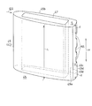
図4に示すように、ストラット47およびその外周を囲むストラットカバー49は、ガスタービン1の軸心方向に沿って細長く延びている。図5Aからわかるように、ストラット47の、ガスタービン1の軸心と同心の円筒面で切断した切断面が、細長いほぼ矩形に形成されており、ストラットカバー49は、その切断面が、ほぼ翼形状に形成されている。図4に示すストラットカバー49の後縁部49aには、ストラットカバー49内部の空気を外部へ排出するための排出孔55が設けられている。ここで、ストラットカバー49の「後縁部」とは、排気ガスEGの流れ方向(ガスタービン1の軸心方向)における下流端およびその近傍の部分を指す。
As shown in FIG. 4, the strut 47 and the strut cover 49 surrounding the outer periphery thereof are elongated along the axial direction of the gas turbine 1. As can be seen from FIG. 5A, the cut surface of the strut 47 cut by a cylindrical surface concentric with the axial center of the gas turbine 1 is formed into an elongated, substantially rectangular shape, and the strut cover 49 has a substantially blade-shaped cut surface. It is formed into a shape. A discharge hole 55 for discharging the air inside the strut cover 49 to the outside is provided in the rear edge portion 49a of the strut cover 49 shown in FIG. Here, the “rear edge” of the strut cover 49 refers to the downstream end in the flow direction of the exhaust gas EG (the axial center direction of the gas turbine 1) and the vicinity thereof.
より詳細には、ストラットカバー49は、その後縁部49aが後側(排気ガスEGの下流側)に向いた平坦面を有し、後縁部49aを除く他の部分は、横断面が翼形に形成されている。すなわち、ストラットカバー49は、前部および側部を形成する、翼形状の湾曲面を有する湾曲部49bと、後部を形成する、平坦面を有する平坦面部49cとを有している。本実施形態では、排出孔55は、湾曲部49bと平坦面部49cとの境界に相当する2つの角部49dの一方のみに設けられている。
More specifically, the strut cover 49 has a flat surface with the rear edge 49a facing the rear side (downstream side of the exhaust gas EG), and the other portions except the rear edge 49a are airfoil in cross section. Is formed. That is, the strut cover 49 has a curved portion 49b having a wing-shaped curved surface that forms a front portion and a side portion, and a flat surface portion 49c having a flat surface that forms a rear portion. In the present embodiment, the discharge hole 55 is provided only in one of the two corner portions 49d corresponding to the boundary between the curved portion 49b and the flat surface portion 49c.
さらに、排出孔55は、ストラットカバー49における排気通路45を横断する方向、つまりストラットカバー49の高さ方向H(この例ではガスタービン1の径方向)に沿って離間して複数(この例では3つ)設けられている。排出孔55を複数設けることにより、後述する第1換気通路VP1および第2換気通路VP2を通って、排気通路45内に導入される換気用空気VA流の分布が均一化される。その結果、換気用空気VA流が排気ガスEG流へ与える影響が抑制されるので、排気ディフューザ33の性能低下が効果的に防止される。
Further, a plurality of exhaust holes 55 are spaced apart (in this example, in a direction crossing the exhaust passage 45 in the strut cover 49, that is, in the height direction H of the strut cover 49 (in this example, the radial direction of the gas turbine 1). 3) provided. By providing a plurality of discharge holes 55, the distribution of the ventilation air VA flow introduced into the exhaust passage 45 through the first ventilation passage VP1 and the second ventilation passage VP2 described later is made uniform. As a result, since the influence of the ventilation air VA flow on the exhaust gas EG flow is suppressed, the performance degradation of the exhaust diffuser 33 is effectively prevented.
ストラットカバー49における排出孔55を設ける位置は、ストラットカバー49の後縁部49aであれば特に限定されない。例えば、ストラットカバー49の平坦面部49cに設けてもよく、湾曲部49bにおける角部49dの近傍に設けてもよい。
The position where the discharge hole 55 is provided in the strut cover 49 is not particularly limited as long as it is the rear edge portion 49 a of the strut cover 49. For example, it may be provided on the flat surface portion 49c of the strut cover 49, or may be provided in the vicinity of the corner portion 49d of the curved portion 49b.
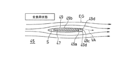
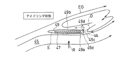
しかし、排気ガスEGは、図5Aに示す全負荷状態では、ガスタービン1の軸心と平行、つまりストラットカバー49の長手方向と平行な流れであるが、アイドリングを含む部分負荷状態では、ガスタービン1の軸心回りの旋回成分を持つ。そこで、本実施形態では、ストラットカバー49の後縁部49aの2つの角部49dのうち、ガスタービン1のアイドリング状態下での排気ガスEGの旋回方向Rにおける下流側に位置する角部49dにのみ排出孔55を設けている。これにより、図5Aに示す全負荷運転状態のみならず、換気用空気VAを吸い込むための負圧不足が特に問題となる図5Bのアイドリング状態においても、ストラットカバー49の周辺で最も負圧が大きくなる領域Dの近傍に排出孔55を設けることとなる。したがって、ガスタービン1のどのような運転状態においても確実に換気用空気VAを排気ディフューザ33内に引き込むことが可能となる。
However, the exhaust gas EG flows parallel to the axis of the gas turbine 1 in the full load state shown in FIG. 5A, that is, parallel to the longitudinal direction of the strut cover 49, but in the partial load state including idling, the gas turbine 1 It has a swivel component around one axis. Therefore, in the present embodiment, of the two corner portions 49d of the rear edge portion 49a of the strut cover 49, the corner portion 49d located on the downstream side in the turning direction R of the exhaust gas EG under the idling state of the gas turbine 1 is used. Only the discharge hole 55 is provided. As a result, not only in the full-load operation state shown in FIG. 5A but also in the idling state in FIG. 5B where the lack of negative pressure for sucking in the ventilation air VA is particularly problematic, the negative pressure is greatest around the strut cover 49. The discharge hole 55 is provided in the vicinity of the region D to be formed. Therefore, it is possible to reliably draw the ventilation air VA into the exhaust diffuser 33 in any operating state of the gas turbine 1.
図4に示すように、横断方向Hにおける排出孔55を設ける範囲としては、ストラットカバー49の高さL、つまり外筒35の内周面と内筒37の外周面との間の径方向における距離を基準として、ストラットカバー49の横断方向Hの両端からの距離dが0.1L以上であることが好ましく、0.15L以上であることがより好ましい。排出孔55をこのような範囲に設けることにより、換気用空気VAによって排気ガスEGが排気ディフューザ33(図1)の内壁面から剥離することが回避され、排気ディフューザ33の性能低下が防止される。
As shown in FIG. 4, the range in which the discharge hole 55 is provided in the transverse direction H is the height L of the strut cover 49, that is, the radial direction between the inner peripheral surface of the outer cylinder 35 and the outer peripheral surface of the inner cylinder 37. On the basis of the distance, the distance d from both ends in the transverse direction H of the strut cover 49 is preferably 0.1 L or more, and more preferably 0.15 L or more. By providing the exhaust hole 55 in such a range, it is avoided that the exhaust gas EG is separated from the inner wall surface of the exhaust diffuser 33 (FIG. 1) by the ventilation air VA, and the performance degradation of the exhaust diffuser 33 is prevented. .
ストラットカバー49に平坦面部49cを設けずに、後部を、例えば湾曲部49bから連続する曲面状に形成して、ストラットカバー49c全体の横断面を完全な翼形としてもよい。しかし、ストラットカバー49の後部を平坦面部49cとして形成することにより、ストラットカバー49の後方(下流側)に、より確実に、負圧を発生させることができる。
Instead of providing the flat surface portion 49c on the strut cover 49, the rear portion may be formed into a curved surface continuous from the curved portion 49b, for example, and the entire cross section of the strut cover 49c may be a complete airfoil. However, by forming the rear portion of the strut cover 49 as the flat surface portion 49c, the negative pressure can be more reliably generated at the rear (downstream side) of the strut cover 49.
図3に示すように、ハウジング19には、さらに、第1の導入口である換気ダクト51とは別に、ハウジング19を貫通する第2の導入口61が設けられている。この第2導入口61からも、外部の空気が換気用空気VAとしてガスタービン1の内部に導入される。より具体的には、第2導入口61は、ハウジング19における、タービン出口31の径方向外側に相当する軸方向位置に設けられている。第2導入口61を設ける軸方向位置は、図示の例に限らないが、換気ダクト51よりも前方の軸方向位置に設けることが好ましく、タービン出口31とストラットカバー49との間の軸方向位置に設けることがより好ましい。
As shown in FIG. 3, the housing 19 is further provided with a second inlet 61 that penetrates the housing 19, separately from the ventilation duct 51 that is the first inlet. External air is also introduced into the gas turbine 1 as ventilation air VA from the second inlet 61. More specifically, the second introduction port 61 is provided at an axial position in the housing 19 corresponding to the radially outer side of the turbine outlet 31. The axial position where the second inlet 61 is provided is not limited to the example shown in the figure, but is preferably provided at an axial position in front of the ventilation duct 51, and the axial position between the turbine outlet 31 and the strut cover 49. More preferably.
このような構成を有するガスタービン1の換気構造において、ストラットカバー49の排出孔55の下流部に発生する負圧によって、換気ダクト(第1導入口)51および第2導入口61を介して外部の空気が換気用空気VAとして導入され、二経路の換気通路VP1,VP2が形成される。すなわち、ハウジング19の外方から第2連結部材43の中空部43aを通り、ストラット47の内径側端部からストラット47とストラットカバー49との間の空間Sを通って、ストラットカバー49の排出孔55から排気通路45内に出る第1の換気通路VP1が形成される。さらに、第2導入口61からハウジング19と外筒35との間を通り、ストラット47とストラットカバー49の間の空間Sを通ってストラットカバー49の排出孔55から排気通路45内に出る第2の換気通路VP2が形成される。
In the ventilation structure of the gas turbine 1 having such a configuration, an external pressure is generated through the ventilation duct (first inlet) 51 and the second inlet 61 due to the negative pressure generated in the downstream portion of the discharge hole 55 of the strut cover 49. Are introduced as ventilation air VA, and two ventilation passages VP1 and VP2 are formed. That is, the discharge hole of the strut cover 49 passes from the outside of the housing 19 through the hollow portion 43 a of the second connecting member 43, through the space S between the strut 47 and the strut cover 49 from the inner diameter side end of the strut 47. A first ventilation passage VP1 is formed from 55 into the exhaust passage 45. Further, the second introduction port 61 passes between the housing 19 and the outer cylinder 35, passes through the space S between the strut 47 and the strut cover 49, and enters the exhaust passage 45 from the discharge hole 55 of the strut cover 49. The ventilation passage VP2 is formed.
第1換気通路VP1により、軸受サポート53を介して軸受29が冷却されるとともに、排気ディフューザ33の内側の空間S1が換気される。また、第2換気通路VP2により、ハウジング19におけるタービン出口31に近い高温となる部分が効果的に冷却される。
The first ventilation passage VP1 cools the bearing 29 via the bearing support 53 and ventilates the space S1 inside the exhaust diffuser 33. Further, the second ventilation passage VP2 effectively cools the portion of the housing 19 that is at a high temperature near the turbine outlet 31.
なお、第2導入口61および第2換気通路VP2は省略してもよいが、換気ダクト(第1導入口)51とは別に第2導入口61を設けて、第1換気通路VP1とは別に第2換気通路VP2を設定することにより、排気ディフューザ33周辺の構造物をより広範囲にかつ効果的に冷却することができる。
Although the second introduction port 61 and the second ventilation passage VP2 may be omitted, a second introduction port 61 is provided separately from the ventilation duct (first introduction port) 51, and separately from the first ventilation passage VP1. By setting the second ventilation passage VP2, the structure around the exhaust diffuser 33 can be cooled more extensively and effectively.
本実施形態に係るタービンの換気構造によれば、排気ディフューザ33内の構造物であるストラットカバー49の後縁部49a、すなわち排気ガスEG流の下流側に換気用空気VAを排出する排出孔55を設けることにより、ストラットカバー49後方領域の負圧を利用して、ガスタービンエンジン1の全負荷運転時のみならず、アイドリング運転時にも安定的に換気用空気VA流を発生させることができる。しかも、換気用空気VAを、排気ディフューザ33の内壁から離間した領域に流すことが可能となるので、排気ディフューザ33の性能低下を防止できる。
According to the turbine ventilation structure according to the present embodiment, the exhaust hole 55 that discharges the ventilation air VA to the rear edge 49a of the strut cover 49 that is a structure in the exhaust diffuser 33, that is, downstream of the exhaust gas EG flow. By providing the above, it is possible to stably generate the ventilation air VA flow not only during the full load operation of the gas turbine engine 1 but also during the idling operation by using the negative pressure in the rear region of the strut cover 49. Moreover, since the ventilation air VA can be flowed to a region separated from the inner wall of the exhaust diffuser 33, the performance of the exhaust diffuser 33 can be prevented from being deteriorated.
以上のとおり、図面を参照しながら本発明の好適な実施形態を説明したが、本発明の趣旨を逸脱しない範囲内で、種々の追加、変更または削除が可能である。したがって、そのようなものも本発明の範囲内に含まれる。
As described above, the preferred embodiments of the present invention have been described with reference to the drawings, but various additions, modifications, or deletions can be made without departing from the spirit of the present invention. Therefore, such a thing is also included in the scope of the present invention.
1 ガスタービンエンジン
3 圧縮機
5 燃焼器
7 タービン
17 ロータ(回転軸)
19 ハウジング
27,29 軸受
33 排気ディフューザ
35 外筒
37 内筒
43 第2連結部材(連結部材)
45 排気通路
47 ストラット
49 ストラットカバー
49a ストラットカバーの中空部
51 換気ダクト(第1の導入口)
55 排出孔
61 第2の導入口
EG 排気ガス
VA 換気用空気VA
VP1 第1の換気通路
VP2 第2の換気通路 1 Gas Turbine Engine 3Compressor 5 Combustor 7 Turbine 17 Rotor (Rotating shaft)
19 Housing 27, 29 Bearing 33 Exhaust diffuser 35 Outer cylinder 37 Inner cylinder 43 Second connecting member (connecting member)
45Exhaust passage 47 Strut 49 Strut cover 49a Strut cover hollow 51 Ventilation duct (first inlet)
55Exhaust hole 61 Second inlet EG Exhaust gas VA Ventilation air VA
VP1 first ventilation passage VP2 second ventilation passage
3 圧縮機
5 燃焼器
7 タービン
17 ロータ(回転軸)
19 ハウジング
27,29 軸受
33 排気ディフューザ
35 外筒
37 内筒
43 第2連結部材(連結部材)
45 排気通路
47 ストラット
49 ストラットカバー
49a ストラットカバーの中空部
51 換気ダクト(第1の導入口)
55 排出孔
61 第2の導入口
EG 排気ガス
VA 換気用空気VA
VP1 第1の換気通路
VP2 第2の換気通路 1 Gas Turbine Engine 3
19
45
55
VP1 first ventilation passage VP2 second ventilation passage
Claims (5)
- 内筒と外筒の間にタービンからの排気ガスが通過する環状の排気通路を形成する排気ディフューザと、
前記外筒の径方向外側のハウジングから前記排気ディフューザを横断して前記内筒の内側の軸受を支持するストラットと、
前記排気通路に配置されて前記ストラットの外周を覆うストラットカバーと、
前記排気通路における前記ストラットカバーの下流側に配置されて、内部に装備品を通す中空部を有し、前記ハウジングと前記内筒とを連結する連結部材とを備え、
前記ハウジングが外部からの空気を導入する第1の導入口を有し、
前記ストラットカバーが、その後縁部に排出孔を有し、さらに、
前記第1導入口から前記連結部材の前記中空部を通り、前記ストラットの内端部から前記ストラットと前記ストラットカバーとの間の空間を通って前記ストラットカバーの前記排出孔から前記排気通路内に出る第1の換気通路が設けられている、
ガスタービンエンジンにおけるタービンの換気構造。 An exhaust diffuser that forms an annular exhaust passage through which exhaust gas from the turbine passes between the inner cylinder and the outer cylinder;
A strut that supports a bearing inside the inner cylinder across the exhaust diffuser from a radially outer housing of the outer cylinder;
A strut cover disposed in the exhaust passage and covering an outer periphery of the strut;
A hollow member that is disposed on the downstream side of the strut cover in the exhaust passage, and has a hollow portion through which equipment is passed, and a connecting member that connects the housing and the inner cylinder;
The housing has a first inlet for introducing air from outside;
The strut cover has a discharge hole at a rear edge thereof;
The first introduction port passes through the hollow portion of the connecting member, passes through the space between the strut and the strut cover from the inner end portion of the strut, and enters the exhaust passage from the discharge hole of the strut cover. A first vent passage is provided,
A turbine ventilation structure in a gas turbine engine. - 請求項1に記載の換気構造において、前記排出孔は、前記ストラットカバーにおける前記排気通路を横断する方向に沿って離間して複数設けられているタービンの換気構造。 2. The ventilation structure according to claim 1, wherein a plurality of the discharge holes are provided apart from each other in a direction crossing the exhaust passage in the strut cover.
- 請求項1または2に記載の換気構造において、前記ストラットカバーは、その後縁部が排気ガスの下流側に向いた平坦面を有し、前記後縁部を除く他の部分の横断面が翼形であるタービンの換気構造。 3. The ventilation structure according to claim 1, wherein the strut cover has a flat surface whose rear edge portion faces the downstream side of the exhaust gas, and a cross section of the other portion excluding the rear edge portion is an airfoil. Is a turbine ventilation structure.
- 請求項1から3のいずれか一項に記載の換気構造において、前記ハウジングに外部からの空気を導入する第2の導入口が設けられており、この第2導入口から前記ハウジングと前記外筒との間を通り、前記ストラットと前記ストラットカバーの間の空間を通って前記ストラットカバーの排出孔から前記排気通路内に出る第2の換気通路をさらに備えるタービンの換気構造。 The ventilation structure according to any one of claims 1 to 3, wherein a second introduction port for introducing air from outside is provided in the housing, and the housing and the outer cylinder are provided from the second introduction port. And a second ventilation passage that passes through a space between the strut and the strut cover and exits from the exhaust hole of the strut cover into the exhaust passage.
- 請求項4に記載の換気構造において、前記第2導入口が前記ハウジングにおけるタービン出口と前記ストラットカバーとの間の軸方向位置に設けられているタービンの換気構造。 The ventilation structure according to claim 4, wherein the second introduction port is provided at an axial position between a turbine outlet in the housing and the strut cover.
Priority Applications (3)
| Application Number | Priority Date | Filing Date | Title |
|---|---|---|---|
| EP15777352.4A EP3130768B1 (en) | 2014-04-07 | 2015-04-02 | Gas turbine engine with turbine ventilation structure |
| CN201580017221.2A CN106460563B (en) | 2014-04-07 | 2015-04-02 | The ventilation of turbine constructs |
| US15/285,910 US10533458B2 (en) | 2014-04-07 | 2016-10-05 | Turbine ventilation structure |
Applications Claiming Priority (2)
| Application Number | Priority Date | Filing Date | Title |
|---|---|---|---|
| JP2014078651A JP5876894B2 (en) | 2014-04-07 | 2014-04-07 | Turbine ventilation structure |
| JP2014-078651 | 2014-04-07 |
Related Child Applications (1)
| Application Number | Title | Priority Date | Filing Date |
|---|---|---|---|
| US15/285,910 Continuation US10533458B2 (en) | 2014-04-07 | 2016-10-05 | Turbine ventilation structure |
Publications (1)
| Publication Number | Publication Date |
|---|---|
| WO2015156200A1 true WO2015156200A1 (en) | 2015-10-15 |
Family
ID=54287777
Family Applications (1)
| Application Number | Title | Priority Date | Filing Date |
|---|---|---|---|
| PCT/JP2015/060461 WO2015156200A1 (en) | 2014-04-07 | 2015-04-02 | Turbine ventilation structure |
Country Status (5)
| Country | Link |
|---|---|
| US (1) | US10533458B2 (en) |
| EP (1) | EP3130768B1 (en) |
| JP (1) | JP5876894B2 (en) |
| CN (1) | CN106460563B (en) |
| WO (1) | WO2015156200A1 (en) |
Families Citing this family (7)
| Publication number | Priority date | Publication date | Assignee | Title |
|---|---|---|---|---|
| JP6862292B2 (en) * | 2017-06-19 | 2021-04-21 | 川崎重工業株式会社 | Gas turbine engine |
| KR101914870B1 (en) * | 2017-06-28 | 2018-12-28 | 두산중공업 주식회사 | Method of disassembling and assembling a gas turbine and a gas turbine assembled thereby |
| KR101965493B1 (en) * | 2017-06-28 | 2019-04-03 | 두산중공업 주식회사 | Method of disassembling and assembling a gas turbine and a gas turbine assembled thereby |
| US11391179B2 (en) | 2019-02-12 | 2022-07-19 | Pratt & Whitney Canada Corp. | Gas turbine engine with bearing support structure |
| US11346249B2 (en) | 2019-03-05 | 2022-05-31 | Pratt & Whitney Canada Corp. | Gas turbine engine with feed pipe for bearing housing |
| KR102441613B1 (en) | 2020-03-05 | 2022-09-06 | 두산에너빌리티 주식회사 | Anti-Separation Strut for Exhaust Diffuser |
| CN115307179B (en) * | 2022-08-15 | 2023-08-01 | 北京航空航天大学 | Curved support plate double-concave-cavity integrated afterburner |
Citations (9)
| Publication number | Priority date | Publication date | Assignee | Title |
|---|---|---|---|---|
| JPS56129725A (en) * | 1980-03-17 | 1981-10-12 | Hitachi Ltd | Method of cooling gas turbine and apparatus therefor |
| JPH01187323A (en) * | 1987-11-05 | 1989-07-26 | General Electric Co <Ge> | Gas turbine engine |
| JP2005083199A (en) * | 2003-09-04 | 2005-03-31 | Hitachi Ltd | Gas turbine equipment and cooling air feeding method |
| JP2007192028A (en) * | 2006-01-17 | 2007-08-02 | Mitsubishi Heavy Ind Ltd | Cooling structure of gas turbine exhaust section and gas turbine facility equipped with the structure |
| JP2011127447A (en) * | 2009-12-15 | 2011-06-30 | Kawasaki Heavy Ind Ltd | Gas turbine engine with improved ventilation structure |
| JP2012149640A (en) * | 2011-01-20 | 2012-08-09 | General Electric Co <Ge> | System and method for gas turbine exhaust diffuser |
| JP2013057302A (en) * | 2011-09-09 | 2013-03-28 | Mitsubishi Heavy Ind Ltd | Gas turbine |
| US20130084172A1 (en) * | 2011-10-03 | 2013-04-04 | General Electric Company | Turbine exhaust section structures with internal flow passages |
| US20130149107A1 (en) * | 2011-12-08 | 2013-06-13 | Mrinal Munshi | Gas turbine outer case active ambient cooling including air exhaust into a sub-ambient region of exhaust flow |
Family Cites Families (9)
| Publication number | Priority date | Publication date | Assignee | Title |
|---|---|---|---|---|
| US2744722A (en) * | 1951-04-06 | 1956-05-08 | Gen Motors Corp | Turbine bearing support |
| US3970252A (en) * | 1967-09-28 | 1976-07-20 | General Motors Corporation | Cooled exhaust duct |
| US5152661A (en) * | 1988-05-27 | 1992-10-06 | Sheets Herman E | Method and apparatus for producing fluid pressure and controlling boundary layer |
| US6746755B2 (en) * | 2001-09-24 | 2004-06-08 | Siemens Westinghouse Power Corporation | Ceramic matrix composite structure having integral cooling passages and method of manufacture |
| JP2004197696A (en) | 2002-12-20 | 2004-07-15 | Kawasaki Heavy Ind Ltd | Gas turbine equipped with whirling nozzle |
| US8029234B2 (en) * | 2007-07-24 | 2011-10-04 | United Technologies Corp. | Systems and methods involving aerodynamic struts |
| JP5118496B2 (en) * | 2008-01-10 | 2013-01-16 | 三菱重工業株式会社 | Gas turbine exhaust structure and gas turbine |
| EP2381071A1 (en) | 2010-04-21 | 2011-10-26 | Siemens Aktiengesellschaft | Exhaust gas diffusor of a gas turbine |
| US8641362B1 (en) * | 2011-09-13 | 2014-02-04 | Florida Turbine Technologies, Inc. | Turbine exhaust cylinder and strut cooling |
-
2014
- 2014-04-07 JP JP2014078651A patent/JP5876894B2/en active Active
-
2015
- 2015-04-02 EP EP15777352.4A patent/EP3130768B1/en active Active
- 2015-04-02 WO PCT/JP2015/060461 patent/WO2015156200A1/en active Application Filing
- 2015-04-02 CN CN201580017221.2A patent/CN106460563B/en active Active
-
2016
- 2016-10-05 US US15/285,910 patent/US10533458B2/en active Active
Patent Citations (9)
| Publication number | Priority date | Publication date | Assignee | Title |
|---|---|---|---|---|
| JPS56129725A (en) * | 1980-03-17 | 1981-10-12 | Hitachi Ltd | Method of cooling gas turbine and apparatus therefor |
| JPH01187323A (en) * | 1987-11-05 | 1989-07-26 | General Electric Co <Ge> | Gas turbine engine |
| JP2005083199A (en) * | 2003-09-04 | 2005-03-31 | Hitachi Ltd | Gas turbine equipment and cooling air feeding method |
| JP2007192028A (en) * | 2006-01-17 | 2007-08-02 | Mitsubishi Heavy Ind Ltd | Cooling structure of gas turbine exhaust section and gas turbine facility equipped with the structure |
| JP2011127447A (en) * | 2009-12-15 | 2011-06-30 | Kawasaki Heavy Ind Ltd | Gas turbine engine with improved ventilation structure |
| JP2012149640A (en) * | 2011-01-20 | 2012-08-09 | General Electric Co <Ge> | System and method for gas turbine exhaust diffuser |
| JP2013057302A (en) * | 2011-09-09 | 2013-03-28 | Mitsubishi Heavy Ind Ltd | Gas turbine |
| US20130084172A1 (en) * | 2011-10-03 | 2013-04-04 | General Electric Company | Turbine exhaust section structures with internal flow passages |
| US20130149107A1 (en) * | 2011-12-08 | 2013-06-13 | Mrinal Munshi | Gas turbine outer case active ambient cooling including air exhaust into a sub-ambient region of exhaust flow |
Also Published As
| Publication number | Publication date |
|---|---|
| CN106460563B (en) | 2018-08-03 |
| JP2015200211A (en) | 2015-11-12 |
| CN106460563A (en) | 2017-02-22 |
| JP5876894B2 (en) | 2016-03-02 |
| US20170022843A1 (en) | 2017-01-26 |
| US10533458B2 (en) | 2020-01-14 |
| EP3130768A4 (en) | 2018-01-10 |
| EP3130768A1 (en) | 2017-02-15 |
| EP3130768B1 (en) | 2020-01-08 |
Similar Documents
| Publication | Publication Date | Title |
|---|---|---|
| JP5876894B2 (en) | Turbine ventilation structure | |
| JP6324548B2 (en) | Gas turbine engine with a rotor centering cooling system in the exhaust diffuser | |
| JP6399894B2 (en) | Exhaust device and gas turbine | |
| KR20100021522A (en) | Exhaust section structure of gas turbine and gas turbine | |
| US9670785B2 (en) | Cooling assembly for a gas turbine system | |
| BR102016007109A2 (en) | airfoil for a turbine frame | |
| US10605266B2 (en) | Gas turbine engine | |
| US20140321981A1 (en) | Turbine engine shutdown temperature control system | |
| EP3196422B1 (en) | Exhaust frame | |
| US20180149024A1 (en) | Turbine blade and gas turbine | |
| JP2012072708A (en) | Gas turbine and method for cooling gas turbine | |
| JP2013151934A (en) | Turbine exhaust diffuser system | |
| US11060726B2 (en) | Compressor diffuser and gas turbine | |
| JP2013060948A (en) | Gas turbine | |
| JP2017538062A (en) | Compressor bleed passage having an auxiliary impeller in the axial bore | |
| JP2016089830A (en) | Turbomachine including transition piece to turbine portion variable purge flow seal member | |
| JP6961340B2 (en) | Rotating machine | |
| JP6194120B2 (en) | gas turbine | |
| JP5529939B2 (en) | Gas turbine exhaust structure and gas turbine | |
| JP5851900B2 (en) | Exhaust diffuser and turbine | |
| JP2012255440A5 (en) | ||
| JP2024011501A (en) | gas turbine | |
| JP2015528878A (en) | Turbine shroud for turbomachine |
Legal Events
| Date | Code | Title | Description |
|---|---|---|---|
| 121 | Ep: the epo has been informed by wipo that ep was designated in this application |
Ref document number: 15777352 Country of ref document: EP Kind code of ref document: A1 |
|
| NENP | Non-entry into the national phase |
Ref country code: DE |
|
| REEP | Request for entry into the european phase |
Ref document number: 2015777352 Country of ref document: EP |
|
| WWE | Wipo information: entry into national phase |
Ref document number: 2015777352 Country of ref document: EP |