WO2015156183A1 - シリンジ - Google Patents
シリンジ Download PDFInfo
- Publication number
- WO2015156183A1 WO2015156183A1 PCT/JP2015/060324 JP2015060324W WO2015156183A1 WO 2015156183 A1 WO2015156183 A1 WO 2015156183A1 JP 2015060324 W JP2015060324 W JP 2015060324W WO 2015156183 A1 WO2015156183 A1 WO 2015156183A1
- Authority
- WO
- WIPO (PCT)
- Prior art keywords
- scale
- barrel
- syringe
- plunger
- shaft portion
- Prior art date
- Legal status (The legal status is an assumption and is not a legal conclusion. Google has not performed a legal analysis and makes no representation as to the accuracy of the status listed.)
- Ceased
Links
Images






Classifications
-
- A—HUMAN NECESSITIES
- A61—MEDICAL OR VETERINARY SCIENCE; HYGIENE
- A61M—DEVICES FOR INTRODUCING MEDIA INTO, OR ONTO, THE BODY; DEVICES FOR TRANSDUCING BODY MEDIA OR FOR TAKING MEDIA FROM THE BODY; DEVICES FOR PRODUCING OR ENDING SLEEP OR STUPOR
- A61M5/00—Devices for bringing media into the body in a subcutaneous, intra-vascular or intramuscular way; Accessories therefor, e.g. filling or cleaning devices, arm-rests
- A61M5/178—Syringes
- A61M5/31—Details
-
- A—HUMAN NECESSITIES
- A61—MEDICAL OR VETERINARY SCIENCE; HYGIENE
- A61M—DEVICES FOR INTRODUCING MEDIA INTO, OR ONTO, THE BODY; DEVICES FOR TRANSDUCING BODY MEDIA OR FOR TAKING MEDIA FROM THE BODY; DEVICES FOR PRODUCING OR ENDING SLEEP OR STUPOR
- A61M5/00—Devices for bringing media into the body in a subcutaneous, intra-vascular or intramuscular way; Accessories therefor, e.g. filling or cleaning devices, arm-rests
- A61M5/178—Syringes
- A61M5/31—Details
- A61M5/315—Pistons; Piston-rods; Guiding, blocking or restricting the movement of the rod or piston; Appliances on the rod for facilitating dosing ; Dosing mechanisms
Definitions
- the present invention relates to a syringe.
- Patent Document 1 Japanese Patent Application Laid-Open No. 2008-99862 is a prior document disclosing a syringe having a scale on each of a barrel and a plunger.
- the syringe described in Patent Document 1 includes a barrel, a plunger formed to be slidable in the barrel, and an outer periphery of the plunger that is fitted to the rear end of the barrel so that the plunger is inserted into the barrel. And a stopper for regulating.
- the syringe described in Patent Document 1 is a so-called prefilled type syringe pre-filled with a chemical solution, and a scale provided on the outer peripheral surface of the plunger displays the dose of the chemical solution.
- a scale provided on the outer peripheral surface of the plunger displays the dose of the chemical solution.
- it is necessary to inhale a desired amount of liquid medicine.
- the plunger When inhaling a desired amount of medicinal solution with a general syringe, the plunger is pulled while looking at the scale provided on the barrel to inhale the medicinal solution. At this time, since the barrel is gripped, the scale may be difficult to see because it is hidden by hand. In this case, it becomes difficult to inhale a desired amount of the drug solution.
- the syringe described in Patent Document 1 is a prefilled type syringe, it is not considered to inhale a desired amount of liquid medicine. Moreover, the syringe described in Patent Document 1 has a substantially cylindrical plunger. For this reason, when a syringe is held with one hand and an attempt is made to inhale the chemical solution, the hand is slippery and it is difficult to inhale the chemical solution.
- the present invention has been made in view of the above problems, and provides a syringe that can inhale or administer a desired amount of medicinal solution and can easily inhale medicinal solution while being held with one hand. For the purpose.
- the syringe according to the present invention is provided at the rear end with a barrel having a chemical inlet / outlet provided at the front end and an opening provided at the rear end, a gasket portion provided at the front end side and sliding with the inner peripheral surface of the barrel.
- a plunger including a shaft portion connecting the gasket portion and the flange portion.
- the plunger further includes an auxiliary scale member attached to the outer peripheral side of the shaft portion and provided with a scale. In the scale, a scale overlapping the rear end of the barrel is attached so as to display the amount of the chemical liquid stored in the barrel or the dose of the chemical liquid stored in the barrel.
- At least a part of the shaft portion includes a plate-like portion that protrudes radially from the shaft center.
- a gap is provided between the auxiliary scale member and the flange portion so that the shaft portion can be clamped.
- the surface of the auxiliary scale member that is graduated is curved so as to follow the inner peripheral surface of the barrel.
- the plunger includes two auxiliary scale members.
- the two auxiliary scale members are respectively provided on opposite sides in the radial direction of the shaft portion.
- the auxiliary scale member is provided over a substantially half circumference in the circumferential direction of the shaft portion.
- a desired amount of medicinal solution can be inhaled or administered, and the medicinal solution can be easily inhaled while being held with one hand.
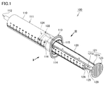
- FIG. 1 is a perspective view showing a state in which a plunger is pulled in the syringe according to Embodiment 1 of the present invention.
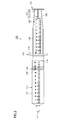
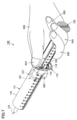
- FIG. 2 is a view of the syringe of FIG. 1 as seen from the direction of arrow II.
- FIG. 3 is a view of the syringe of FIG. 1 as viewed from the direction of arrow III.
- FIG. 4 is a perspective view showing a state where the plunger is pushed in the syringe according to the first embodiment of the present invention.
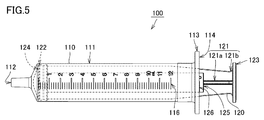
- FIG. 5 is a view of the syringe of FIG.
- the syringe 100 includes a barrel 110 and a plunger 120.
- the barrel 110 has a cylindrical storage portion 111 that stores a chemical solution therein.
- a chemical solution inlet / outlet port 112 is provided at the tip of the barrel 110.
- An opening 115 is provided at the rear end of the barrel 110.
- a first scale 116 is attached to the outer peripheral surface of the barrel 110.
- a chemical solution inlet / outlet port 112 to which an injection needle or the like can be attached is provided on the distal end side of the accommodating portion 111.
- a flange 113 having a rear end surface 114 perpendicular to the axis of the accommodating portion 111 is provided around the opening 115.
- a first scale 116 is attached to the outer peripheral surface of the accommodating portion 111.
- the barrel 110 is made of a transparent or translucent resin such as polypropylene.
- Lubricating oil such as silicone oil is applied to the inner peripheral surface of the barrel 110.
- a gasket portion 122 that slides with the inner peripheral surface of the barrel 110 is provided on the distal end side of the plunger 120.
- a flange portion 123 is provided at the rear end of the plunger 120.
- the plunger 120 includes a shaft portion 121 that connects the gasket portion 122 and the flange portion 123.
- the plunger 120 further includes an auxiliary scale member 125 attached to the outer peripheral side of the shaft portion 121 and provided with a second scale 126.
- the gasket portion 122 has an outer diameter slightly larger than the inner diameter of the accommodating portion 111.
- the gasket part 122 is comprised with elastic bodies, such as a vulcanized rubber or a thermoplastic elastomer.
- the gasket portion 122 is in close contact with the inner peripheral surface of the housing portion 111 over the entire circumference in a state of being inserted into the housing portion 111.
- a tip surface 124 that is perpendicular to the axis of the shaft portion 121 is formed at the tip of the gasket portion 122.
- the shaft portion 121, the flange portion 123, and the auxiliary scale member 125 are integrally formed by injection molding a resin such as polypropylene.
- the shaft portion 121 and the flange portion 123 may be integrally formed, and a separate auxiliary scale member 125 may be attached to the shaft portion 121.
- At least a part of the shaft part 121 includes a plate-like part protruding radially from the axis.
- the shaft portion 121 is composed of two plate-like portions 121a and 121b that are orthogonal to each other, and has a substantially cross shape in cross section.
- the rigidity of the shaft 121 is secured while reducing the resin material to be used, and the plunger 120 is pushed into the barrel 110. Deformation can be suppressed.
- the shape of the shaft portion 121 is not limited to the above, and may be any shape that can suppress the deformation of the plunger 120 when being pushed into the barrel 110.
- at least a part of the shaft 121 may have a star shape in the cross section.
- the front end of the shaft portion 121 is connected to the rear end of the gasket portion 122.
- the flange portion 123 is provided with a plurality of recesses or protrusions for preventing slipping at intervals.
- the diameter of the flange portion 123 is slightly larger than the inner diameter of the accommodating portion 111.
- the auxiliary scale member 125 is provided at one end portion in the radial direction of the shaft portion 121 in one plate-like portion 121a of two plate-like portions constituting the shaft portion 121. .
- the auxiliary scale member 125 is provided so as to face the other plate-like portion 121b of the two plate-like portions.
- a gap 129 is provided between the auxiliary scale member 125 and the flange portion 123 so that the shaft portion 121 can be clamped.
- the surface to which the second scale 126 is attached is curved so as to follow the inner peripheral surface of the barrel 110.
- the surface to which the second scale 126 is attached may be a flat surface.
- the user when inhaling the drug solution, the user can visually recognize whichever one of the first scale 116 provided on the barrel 110 and the second scale 126 provided on the plunger 120 is easier to see, The amount of the chemical solution sucked into the barrel 110 can be confirmed.
- a scale that overlaps the tip surface 124 of the gasket portion 122 is attached so as to display the amount of the chemical solution stored in the barrel 110.
- a scale that overlaps the rear end surface 114 of the flange 113 of the barrel 110 is attached so as to display the amount of the chemical solution stored in the barrel 110.
- the scale that overlaps the front end surface 124 of the gasket portion 122 in the first scale 116 is 10 ml
- the scale that overlaps the rear end face 114 of the flange 113 in the second scale 126 is also 10 ml.
- 10 ml of the chemical solution is accommodated in the barrel 110.
- the scale which overlaps the front end surface 124 of the gasket part 122 in the first scale 116 is 0 ml
- the scale which overlaps the rear end face 114 of the flange 113 in the second scale 126 is also 0 ml.
- 0 ml of the chemical solution is stored in the barrel 110. That is, the chemical solution is not stored in the barrel 110.
- the measurable amount of medicinal solution can be confirmed by visually checking the scale that is easy to see, so that the medicinal solution having a desired amount can be inhaled.
- auxiliary scale member 125 is attached to the outer peripheral side of the shaft portion 121, the second scale 126 and the rear end surface 114 of the flange 113 approach each other, and the scale at the position where the two scales overlap is easy to read.
- the surface to which the second scale 126 is attached is curved so as to be along the inner peripheral surface of the barrel 110, so that the second scale 126 and the rear end surface 114 of the flange 113 are closer to each other. In addition, it is easier to read the scale where the two overlap.
- the first scale 116 and the second scale 126 have the same scale width, but may have different scale widths.
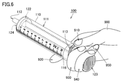
- FIG. 6 is a perspective view showing a state in which the syringe before the plunger is pulled is held with one hand.
- FIG. 7 is a perspective view showing a state where the plunger is pulled with one hand.
- the middle finger 930 and the ring finger 940 are inserted between the flange 113 and the flange portion 123, and the inside of the ring finger 940 is inserted.
- a ring is formed with the outside of the little finger 950 and the ring is hooked on the flange portion 123.
- the thumb 910 is pressed against the flange 113, and the index finger 920 is lightly applied to the housing portion 111 to sandwich the barrel 110.
- the plunger 120 can be pulled from the barrel 110 by pulling the barrel 110 and the plunger 120 apart by pushing up the flange 113 with the thumb 910.
- the second scale 126 that overlaps the rear end surface 114 of the flange 113 of the barrel 110 is not covered by the hand and is visible.
- the syringe 100 according to the present embodiment can easily inhale a desired amount of chemical liquid while being held with one hand. If the plunger has a cylindrical outer shape, if the plunger is pulled while being held with one hand, the hand and the plunger are not sufficiently caught, and the hand may easily slip and inhale the chemical solution. Have difficulty.
- the gap 129 is provided between the auxiliary scale member 125 and the flange portion 123 so that the shaft portion 121 can be sandwiched, the shaft portion between the inner side of the ring finger 940 and the outer side of the little finger 950 is provided. 121 can be held. As a result, since the flange portion 123 can be firmly hooked on the ring formed by the inner side of the ring finger 940 and the outer side of the little finger 950, the one hand 900 can be more reliably prevented from slipping when the plunger 120 is pulled.
- FIG. 8 is a perspective view showing a state where the plunger is pulled in the syringe according to the present modification.
- FIG. 9 is a view of the syringe of FIG. 8 as viewed from the direction of the arrow IX.
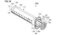
- FIG. 10 is a perspective view showing a state in which the plunger is pushed in the syringe according to this modification.
- the auxiliary scale member 125 a is provided over a substantially half circumference in the circumferential direction of the shaft portion 121. As shown in FIG. 9, the auxiliary scale member 125a has a substantially semi-cylindrical shape. The front end of the auxiliary scale member 125 a is in contact with the rear end of the gasket portion 122.
- the shaft portion 121 is composed of two plate-like portions 121a and 121b that are orthogonal to each other only between the flange portion 123 and the auxiliary scale member 125a.
- only one plate-like portion 121a of the two plate-like portions is provided from the front end to the rear end of the shaft portion 121.
- the other plate-like portion 121b of the two plate-like portions is provided only between the flange portion 123 and the auxiliary scale member 125a.
- a plurality of partition plate portions 121c orthogonal to one of the two plate-like portions 121a are provided at intervals.
- the syringe 100a according to this modification has higher rigidity than the plunger 120 of the syringe 100 according to the first embodiment because the plunger 120 has the above-described shape. Therefore, in the syringe 100a according to the present modification, the deformation of the plunger 120 when pushed into the barrel 110 can be suppressed from the syringe 100 according to the first embodiment. As a result, the drug solution can be more stably administered from the drug solution inlet / outlet 112.
- the syringe 200 according to the second embodiment of the present invention is different from the syringe 100 according to the first embodiment only in that the two auxiliary scale members 125 are provided, and the description of the other configurations will not be repeated.
- FIG. 11 is a perspective view showing a state where the plunger is pulled in the syringe according to the second embodiment of the present invention.
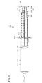
- 12 is a view of the syringe of FIG. 11 as viewed from the direction of arrow XII.
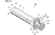
- FIG. 13 is a perspective view showing a state where the plunger is pushed in the syringe according to the second embodiment of the present invention.
- the plunger 120 includes two auxiliary scale members 125.
- the two auxiliary scale members 125 are respectively provided on opposite sides in the radial direction of the shaft portion 121.
- the two auxiliary scale members 125 are respectively provided at both end portions in the radial direction of the shaft portion 121 in one plate-like portion 121 a of the two plate-like portions constituting the shaft portion 121. .
- the two auxiliary scale members 125 are provided so as to face the other plate-like portion 121b of the two plate-like portions, respectively.
- the syringe 200 according to the present embodiment since the plunger 120 includes two auxiliary scale members 125, when inhaling the chemical liquid, the amount of the chemical liquid inhaled by visually observing the second scale 126 that is easy to see is determined. I can confirm. As a result, the syringe 200 according to the present embodiment can inhale a drug solution of a desired liquid amount more easily than the syringe 100 according to the first embodiment.
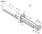
- FIG. 14 is a perspective view illustrating a state where the plunger is pulled in the syringe according to the third embodiment of the present invention.
- FIG. 15 is a perspective view illustrating a state where the plunger is pushed in the syringe according to the third embodiment of the present invention.
- the second scale 326 of the auxiliary scale member 125 of the plunger 320 has a scale that overlaps the rear end surface 114 of the flange 113 of the barrel 110. The dose of the chemical contained in the barrel 110 is displayed.
- the scale that overlaps the rear end surface 114 of the flange 113 in the second scale 326 is 2 ml.
- 2 ml of 12 ml of the chemical solution stored in the barrel 110 is administered.
- the scale which overlaps with the rear-end surface 114 of the flange 113 in the 2nd scale 326 is 12 ml.
- 12 ml of 12 ml of the chemical solution housed in the barrel 110 is administered. That is, it is a state in which all of the chemical liquid stored in the barrel 110 is administered.
- the first scale 116 is attached so as to display the amount of the chemical liquid stored in the barrel 110
- the second scale 326 is the chemical liquid stored in the barrel 110. It is attached to display the dose.
- the amount of the inhaled medicinal solution can be confirmed by visually checking the first scale 116, and when the medicinal solution is administered, the second scale 326 is confirmed. It is possible to confirm the liquid volume of the administered drug solution by visually checking.
- the first scale 116 does not necessarily have to be attached to the barrel 110.
- the drug solution having a desired amount can be administered by visually confirming the second scale 326 and confirming the amount of the administered drug solution.
Landscapes
- Health & Medical Sciences (AREA)
- Vascular Medicine (AREA)
- Engineering & Computer Science (AREA)
- Anesthesiology (AREA)
- Biomedical Technology (AREA)
- Heart & Thoracic Surgery (AREA)
- Hematology (AREA)
- Life Sciences & Earth Sciences (AREA)
- Animal Behavior & Ethology (AREA)
- General Health & Medical Sciences (AREA)
- Public Health (AREA)
- Veterinary Medicine (AREA)
- Infusion, Injection, And Reservoir Apparatuses (AREA)
Abstract
シリンジは、先端に設けられた薬液出入口(112)および後端に設けられた開口(115)を有するバレル(110)と、先端側に設けられてバレル(110)の内周面と摺動するガスケット部(122)、後端に設けられたフランジ部(123)、および、ガスケット部(122)とフランジ部(123)とを結ぶ軸部(121)を含むプランジャ(120)とを備える。プランジャ(120)は、軸部(121)の外周側に付設されて第2目盛(126)が付された補助目盛部材(125)をさらに含む。第2目盛(126)においては、バレル(110)の後端(114)と重なる目盛が、バレル(110)の内部に収容されている薬液量またはバレル(110)の内部に収容された薬液の投与量を表示するように付されている。
Description
本発明は、シリンジに関する。
バレルおよびプランジャの各々に目盛を設けたシリンジを開示した先行文献として、特開2008-99862号公報(特許文献1)がある。特許文献1に記載されたシリンジは、バレルと、バレル内を摺動自在に形成されたプランジャと、プランジャの外周に嵌装されバレルの後端に衝止することによりプランジャのバレルへの挿入を規制するストッパとを備える。
特許文献1に記載されたシリンジは、薬液を予め充填したいわゆるプレフィルドタイプのシリンジであり、プランジャの外周面に設けられた目盛は薬液の投与量を表示している。プレフィルドタイプ以外のシリンジにおいては、所望の液量の薬液を吸入する必要がある。
一般的なシリンジにおいて所望の液量の薬液を吸入する際には、バレルに設けられた目盛を見ながらプランジャを引いて薬液を吸入する。この時、バレルを把持しているため、目盛が手で隠れて見え難くなることがある。この場合、所望の液量の薬液を吸入することが困難となる。
ディスポーザブルシリンジにおいては、薬液が吸入された後のバイアルに貼られていたラベルから切り取られた薬液名表示部が、バレルの表面に貼り付けられることにより、誤投与の防止が図られることがある。そのため、バレルに設けられた目盛が、薬液名表示部によって覆われて見え難くなることがある。この場合、所望の液量の薬液を投与することが困難となる。
特許文献1に記載されたシリンジは、プレフィルドタイプのシリンジであるため、所望の液量の薬液を吸入することについては考慮されていない。また、特許文献1に記載されたシリンジは、略円柱状のプランジャを有している。そのため、片手でシリンジを把持して薬液を吸入しようとした場合、手が滑りやすく薬液を吸入することが困難である。
本発明は上記の問題点に鑑みてなされたものであって、所望の液量の薬液を吸入または投与可能であり、かつ、片手で把持した状態で薬液を容易に吸入できる、シリンジを提供することを目的とする。
本発明に基づくシリンジは、先端に設けられた薬液出入口および後端に設けられた開口を有するバレルと、先端側に設けられてバレルの内周面と摺動するガスケット部、後端に設けられたフランジ部、および、ガスケット部とフランジ部とを結ぶ軸部を含むプランジャとを備える。プランジャは、軸部の外周側に付設されて目盛が付された補助目盛部材をさらに含む。上記目盛においては、バレルの後端と重なる目盛が、バレルの内部に収容されている薬液量またはバレルの内部に収容された薬液の投与量を表示するように付されている。
本発明の一形態においては、軸部の少なくとも一部は、軸心から放射状に突出した板状部を含む。
本発明の一形態においては、補助目盛部材とフランジ部との間に、軸部を挟持可能とする隙間が設けられている。
本発明の一形態においては、補助目盛部材において、目盛が付されている面が、バレルの内周面に沿うように湾曲している。
本発明の一形態においては、プランジャが2つの補助目盛部材を含む。2つの補助目盛部材は、軸部の径方向において互いに反対側にそれぞれ設けられている。
本発明の一形態においては、補助目盛部材が、軸部の周方向において略半周に亘って設けられている。
本発明によれば、所望の液量の薬液を吸入または投与可能であり、かつ、片手で把持した状態で薬液を容易に吸入できる。
以下、本発明の各実施形態に係るシリンジについて図面を参照して説明する。以下の実施形態の説明においては、図中の同一または相当部分には同一符号を付して、その説明は繰り返さない。
(実施形態1)
図1は、本発明の実施形態1に係るシリンジにおいてプランジャが引かれた状態を示す斜視図である。図2は、図1のシリンジを矢印II方向から見た図である。図3は、図1のシリンジを矢印III方向から見た図である。図4は、本発明の実施形態1に係るシリンジにおいてプランジャが押し込まれた状態を示す斜視図である。図5は、図4のシリンジを矢印V方向から見た図である。
図1は、本発明の実施形態1に係るシリンジにおいてプランジャが引かれた状態を示す斜視図である。図2は、図1のシリンジを矢印II方向から見た図である。図3は、図1のシリンジを矢印III方向から見た図である。図4は、本発明の実施形態1に係るシリンジにおいてプランジャが押し込まれた状態を示す斜視図である。図5は、図4のシリンジを矢印V方向から見た図である。
図1~5に示すように、本発明の実施形態1に係るシリンジ100は、バレル110とプランジャ120とを備える。バレル110は、内部に薬液を収容する円筒状の収容部111を有する。バレル110の先端には、薬液出入口112が設けられている。バレル110の後端には、開口115が設けられている。バレル110の外周面には、第1目盛116が付されている。
具体的には、収容部111の先端側において、注射針などが取り付け可能な薬液出入口112が設けられている。収容部111の後端側において、収容部111の軸心と互いに垂直である後端面114を有するフランジ113が、開口115の周囲に設けられている。収容部111の外周面に、第1目盛116が付されている。
バレル110は、ポリプロピレンなどの透明または半透明の樹脂にて構成されている。バレル110の内周面には、シリコーンオイルなどの潤滑油が塗布されている。
プランジャ120の先端側には、バレル110の内周面と摺動するガスケット部122が設けられている。プランジャ120の後端には、フランジ部123が設けられている。プランジャ120は、ガスケット部122とフランジ部123とを結ぶ軸部121を含む。プランジャ120は、軸部121の外周側に付設されて第2目盛126が付された補助目盛部材125をさらに含む。
具体的には、ガスケット部122は、収容部111の内径より僅かに大きい外径を有する。ガスケット部122は、加硫ゴムまたは熱可塑性エラストマなどの弾性体で構成されている。ガスケット部122は、収容部111内に挿入された状態で、収容部111の内周面と全周に亘って密着する。ガスケット部122の先端には、軸部121の軸心と互いに垂直である先端面124が形成されている。
本実施形態においては、軸部121、フランジ部123および補助目盛部材125は、ポリプロピレンなどの樹脂を射出成形することにより一体で構成されている。ただし、軸部121とフランジ部123とが一体で構成され、軸部121に別体の補助目盛部材125が取り付けられていてもよい。
軸部121の少なくとも一部は、軸心から放射状に突出した板状部を含む。本実施形態においては、軸部121は、互いに直交する2つの板状部121a,121bから構成されて、横断面にて略十字形状を有する。
軸部121の少なくとも一部を横断面にて略十字形状とすることにより、使用する樹脂材料を削減しつつ軸部121の剛性を確保して、バレル110の内部に押し込まれる際のプランジャ120の変形を抑制することができる。
ただし、軸部121の形状は、上記に限られず、バレル110の内部に押し込まれる際のプランジャ120の変形を抑制可能な形状であればよい。たとえば、軸部121の少なくとも一部が、横断面にて星印形状を有していてもよい。軸部121の先端は、ガスケット部122の後端と接続されている。
フランジ部123には、滑り止め用の複数の凹部または凸部が互いに間隔を置いて設けられている。本実施形態においては、フランジ部123の直径は、収容部111の内径より僅かに大きい。
本実施形態においては、補助目盛部材125は、軸部121を構成する2つの板状部のうちの一方の板状部121aにおいて、軸部121の径方向の一方の端部に設けられている。また、補助目盛部材125は、2つの板状部のうちの他方の板状部121bと対向するように設けられている。補助目盛部材125とフランジ部123との間に、軸部121を挟持可能とする隙間129が設けられている。
補助目盛部材125において、第2目盛126が付されている面は、バレル110の内周面に沿うように湾曲している。ただし、補助目盛部材125において、第2目盛126が付されている面が平坦面であってもよい。
本実施形態に係るシリンジ100においては、薬液を吸入する際に、バレル110に設けられた第1目盛116およびプランジャ120に設けられた第2目盛126のいずれか見易い方の目盛を視認して、バレル110内に吸入した薬液の液量を確認できる。
具体的には、第1目盛116においては、ガスケット部122の先端面124と重なる目盛が、バレル110の内部に収容されている薬液量を表示するように付されている。第2目盛126においては、バレル110のフランジ113の後端面114と重なる目盛が、バレル110の内部に収容されている薬液量を表示するように付されている。
たとえば、図2においては、第1目盛116におけるガスケット部122の先端面124と重なる目盛は10mlであり、第2目盛126におけるフランジ113の後端面114と重なる目盛も10mlである。この状態においては、バレル110の内部に薬液が10ml収容されている。
図5においては、第1目盛116におけるガスケット部122の先端面124と重なる目盛は0mlであり、第2目盛126におけるフランジ113の後端面114と重なる目盛も0mlである。この状態においては、バレル110の内部に薬液が0ml収容されている。すなわち、バレル110の内部に薬液が収容されていない状態である。
このように、本実施形態に係るシリンジ100においては、薬液を吸入する際に、見易い方の目盛を視認して吸入した薬液の液量を確認できることにより、所望の液量の薬液を吸入できる。
また、補助目盛部材125が軸部121の外周側に付設されていることにより、第2目盛126とフランジ113の後端面114とが接近し、両者が重なった位置の目盛が読み易くなる。
補助目盛部材125において、第2目盛126が付されている面が、バレル110の内周面に沿うように湾曲していることにより、第2目盛126とフランジ113の後端面114とがさらに接近し、両者が重なった位置の目盛がより読み易くなる。
上記のように、第2目盛126とフランジ113の後端面114とが重なった位置の目盛が読み易くなることにより、シリンジ100を用いて薬液を吸入する際に、所望の液量の薬液を吸入できるようになる。本実施形態においては、第1目盛116と第2目盛126とは、同一の目幅を有しているが、互いに異なる目幅を有していてもよい。
次に、本実施形態に係るシリンジ100を片手で把持した状態で薬液を吸入する方法について説明する。図6は、プランジャが引かれる前のシリンジを片手で把持した状態を示す斜視図である。図7は、プランジャを片手で引いた状態を示す斜視図である。
図6に示すように、プランジャ120が引かれる前のシリンジ100を片手900で把持する際には、フランジ113とフランジ部123との間に、中指930および薬指940を入れて、薬指940の内側と小指950の外側とで輪を作り、その輪をフランジ部123に引っ掛けた状態にする。さらに、親指910をフランジ113に押し当て、人差し指920を軽く収容部111に当ててバレル110を挟み持つ。
図7に示すように、親指910でフランジ113を突き上げるようにしてバレル110とプランジャ120とを引き離すことにより、バレル110からプランジャ120を引くことができる。この状態において、バレル110のフランジ113の後端面114と重なる第2目盛126は、手に覆われておらず視認可能である。このようにして、本実施形態に係るシリンジ100は、片手で把持した状態で所望の液量の薬液を容易に吸入できる。仮に、プランジャが円柱状の外形を有している場合、片手で把持した状態でプランジャを引くと、手とプランジャとの引っ掛かりが不十分であるために、手が滑りやすく薬液を吸入することが困難である。
また、上記のように、補助目盛部材125とフランジ部123との間に、軸部121を挟持可能とする隙間129が設けられているため、薬指940の内側と小指950の外側とで軸部121を挟持することができる。その結果、薬指940の内側と小指950の外側とで作られた輪にフランジ部123をしっかりと引っ掛けることができるため、プランジャ120を引く際に片手900が滑ることをより確実に抑制できる。
以下、本実施形態に係るシリンジ100の変形例について説明する。なお、本変形例に係るシリンジ100aは、補助目盛部材125aの形状のみ、実施形態1に係るシリンジ100と異なるため、他の構成については説明を繰り返さない。
図8は、本変形例に係るシリンジにおいてプランジャが引かれた状態を示す斜視図である。図9は、図8のシリンジを矢印IX方向から見た図である。図10は、本変形例に係るシリンジにおいてプランジャが押し込まれた状態を示す斜視図である。
図8~10に示すように、本変形例に係るシリンジ100aにおいては、補助目盛部材125aが、軸部121の周方向において略半周に亘って設けられている。図9に示すように、補助目盛部材125aは、略半円筒形状を有している。補助目盛部材125aの先端は、ガスケット部122の後端と接している。
本変形例に係るシリンジ100aにおいては、軸部121は、フランジ部123と補助目盛部材125aとの間においてのみ、互いに直交する2つの板状部121a,121bから構成されている。
具体的には、2つの板状部のうちの一方の板状部121aのみ、軸部121の先端から後端に亘って設けられている。2つの板状部のうちの他方の板状部121bは、フランジ部123と補助目盛部材125aとの間にのみ設けられている。補助目盛部材125aの内側には、2つの板状部のうちの一方の板状部121aと直交する複数の仕切板部121cが、互いに間隔を置いて設けられている。
本変形例に係るシリンジ100aにおいては、プランジャ120が上記の形状を有していることにより、実施形態1に係るシリンジ100のプランジャ120より高い剛性を有している。そのため、本変形例に係るシリンジ100aにおいては、バレル110の内部に押し込まれる際のプランジャ120の変形を、実施形態1に係るシリンジ100より抑制することができる。その結果、薬液出入口112からより安定して薬液を投与することができる。
以下、本発明の実施形態2に係るシリンジについて説明する。なお、本発明の実施形態2に係るシリンジ200は、2つの補助目盛部材125が設けられている点のみ、実施形態1に係るシリンジ100と異なるため、他の構成については説明を繰り返さない。
(実施形態2)
図11は、本発明の実施形態2に係るシリンジにおいてプランジャが引かれた状態を示す斜視図である。図12は、図11のシリンジを矢印XII方向から見た図である。図13は、本発明の実施形態2に係るシリンジにおいてプランジャが押し込まれた状態を示す斜視図である。
図11は、本発明の実施形態2に係るシリンジにおいてプランジャが引かれた状態を示す斜視図である。図12は、図11のシリンジを矢印XII方向から見た図である。図13は、本発明の実施形態2に係るシリンジにおいてプランジャが押し込まれた状態を示す斜視図である。
図11~13に示すように、本発明の実施形態2に係るシリンジ200においては、プランジャ120が2つの補助目盛部材125を含む。2つの補助目盛部材125は、軸部121の径方向において互いに反対側にそれぞれ設けられている。
具体的には、2つの補助目盛部材125は、軸部121を構成する2つの板状部のうちの一方の板状部121aにおいて、軸部121の径方向の両端部にそれぞれ設けられている。また、2つの補助目盛部材125は、2つの板状部のうちの他方の板状部121bとそれぞれ対向するように設けられている。
本実施形態に係るシリンジ200においては、プランジャ120が2つの補助目盛部材125を備えているため、薬液を吸入する際に、見易い方の第2目盛126を視認して吸入した薬液の液量を確認できる。その結果、本実施形態に係るシリンジ200は、実施形態1に係るシリンジ100と比較して、より容易に、所望の液量の薬液を吸入できる。
以下、本発明の実施形態3に係るシリンジについて説明する。なお、本発明の実施形態3に係るシリンジ300は、補助目盛部材の第2目盛のみ、実施形態1に係るシリンジ100と異なるため、他の構成については説明を繰り返さない。
(実施形態3)
図14は、本発明の実施形態3に係るシリンジにおいてプランジャが引かれた状態を示す斜視図である。図15は、本発明の実施形態3に係るシリンジにおいてプランジャが押し込まれた状態を示す斜視図である。
図14は、本発明の実施形態3に係るシリンジにおいてプランジャが引かれた状態を示す斜視図である。図15は、本発明の実施形態3に係るシリンジにおいてプランジャが押し込まれた状態を示す斜視図である。
図14,15に示すように、本発明の実施形態3に係るシリンジ300においては、プランジャ320の補助目盛部材125の第2目盛326においては、バレル110のフランジ113の後端面114と重なる目盛が、バレル110の内部に収容された薬液の投与量を表示するように付されている。
たとえば、図14においては、第2目盛326におけるフランジ113の後端面114と重なる目盛は2mlである。この状態においては、バレル110の内部に収容された12mlの薬液のうちの2mlが投与されている。図15においては、第2目盛326におけるフランジ113の後端面114と重なる目盛は12mlである。この状態においては、バレル110の内部に収容された12mlの薬液のうちの12mlが投与されている。すなわち、バレル110の内部に収容された薬液の全てが投与された状態である。
本実施形態に係るシリンジ300においては、第1目盛116は、バレル110の内部に収容されている薬液量を表示するように付され、第2目盛326は、バレル110の内部に収容された薬液の投与量を表示するように付されている。
よって、本実施形態に係るシリンジ300においては、薬液を吸入する際には、第1目盛116を視認して吸入した薬液の液量を確認でき、薬液を投与する際には、第2目盛326を視認して投与した薬液の液量を確認できる。なお、必ずしもバレル110に第1目盛116が付されていなくてもよい。
このように、本実施形態に係るシリンジ300においては、薬液を投与する際に、第2目盛326を視認して投与した薬液の液量を確認できることにより、所望の液量の薬液を投与できる。
なお、今回開示した上記実施形態はすべての点で例示であって、限定的な解釈の根拠となるものではない。したがって、本発明の技術的範囲は、上記した実施形態のみによって解釈されるものではなく、請求の範囲の記載に基づいて画定される。また、請求の範囲と均等の意味および範囲内でのすべての変更が含まれる。
100,100a,200,300 シリンジ、110 バレル、111 収容部、112 薬液出入口、113 フランジ、114 後端面、115 開口、116 第1目盛、120,320 プランジャ、121 軸部、121a,121b 板状部、121c 仕切板部、122 ガスケット部、123 フランジ部、124 先端面、125,125a 補助目盛部材、126,326 第2目盛、129 隙間、900 片手、910 親指、920 人差し指、930 中指、940 薬指、950 小指。
Claims (6)
- 先端に設けられた薬液出入口および後端に設けられた開口を有するバレルと、
先端側に設けられて前記バレルの内周面と摺動するガスケット部、後端に設けられたフランジ部、および、該ガスケット部と該フランジ部とを結ぶ軸部を含むプランジャとを備え、
前記プランジャは、前記軸部の外周側に付設されて目盛が付された補助目盛部材をさらに含み、
前記目盛においては、前記バレルの後端と重なる目盛が、前記バレルの内部に収容されている薬液量または前記バレルの内部に収容された薬液の投与量を表示するように付されている、シリンジ。 - 前記軸部の少なくとも一部は、軸心から放射状に突出した板状部を含む、請求項1に記載のシリンジ。
- 前記補助目盛部材と前記フランジ部との間に、前記軸部を挟持可能とする隙間が設けられている、請求項1または2に記載のシリンジ。
- 前記補助目盛部材において、前記目盛が付されている面が、前記バレルの前記内周面に沿うように湾曲している、請求項1から3のいずれか1項に記載のシリンジ。
- 前記プランジャが2つの前記補助目盛部材を含み、
2つの前記補助目盛部材は、前記軸部の径方向において互いに反対側にそれぞれ設けられている、請求項1から4のいずれか1項に記載のシリンジ。 - 前記補助目盛部材が、前記軸部の周方向において略半周に亘って設けられている、請求項1から4のいずれか1項に記載のシリンジ。
Priority Applications (1)
| Application Number | Priority Date | Filing Date | Title |
|---|---|---|---|
| JP2016512683A JP6520926B2 (ja) | 2014-04-07 | 2015-04-01 | シリンジ |
Applications Claiming Priority (2)
| Application Number | Priority Date | Filing Date | Title |
|---|---|---|---|
| JP2014-078508 | 2014-04-07 | ||
| JP2014078508 | 2014-04-07 |
Publications (1)
| Publication Number | Publication Date |
|---|---|
| WO2015156183A1 true WO2015156183A1 (ja) | 2015-10-15 |
Family
ID=54287760
Family Applications (1)
| Application Number | Title | Priority Date | Filing Date |
|---|---|---|---|
| PCT/JP2015/060324 Ceased WO2015156183A1 (ja) | 2014-04-07 | 2015-04-01 | シリンジ |
Country Status (2)
| Country | Link |
|---|---|
| JP (1) | JP6520926B2 (ja) |
| WO (1) | WO2015156183A1 (ja) |
Cited By (5)
| Publication number | Priority date | Publication date | Assignee | Title |
|---|---|---|---|---|
| WO2019123491A1 (en) * | 2017-12-19 | 2019-06-27 | Matex Lab S.P.A. | Pusher unit for a syringe, and corresponding syringe |
| JP2020150998A (ja) * | 2019-03-18 | 2020-09-24 | 住友ベークライト株式会社 | シリンジ |
| JP2021507771A (ja) * | 2017-12-21 | 2021-02-25 | クルツァー ゲゼルシャフト ミット ベシュレンクテル ハフツングKulzer GmbH | 特に歯科用ペースト状組成物を投与するための、後流無しの注射器 |
| CN113304377A (zh) * | 2021-04-25 | 2021-08-27 | 山东大学齐鲁医院 | 一种麻醉用注射器 |
| JP2022540955A (ja) * | 2019-07-18 | 2022-09-20 | アイエスピー インヴェストメンツ エルエルシー | シリンジのための放射線感受性インジケータを備える可撓性自己接着性ラベル |
Citations (6)
| Publication number | Priority date | Publication date | Assignee | Title |
|---|---|---|---|---|
| JPS6151828U (ja) * | 1984-09-10 | 1986-04-08 | ||
| US5376081A (en) * | 1991-03-25 | 1994-12-27 | Sapienza; Salvatore | Opaque syringe |
| JP2003199828A (ja) * | 2001-12-28 | 2003-07-15 | Terumo Corp | シリンジ |
| US20040024365A1 (en) * | 2001-02-28 | 2004-02-05 | Mats Bonnier | Injection syringe having dosage device |
| US20070244444A1 (en) * | 2006-03-13 | 2007-10-18 | Guelker Benjamin R | Adjustable dosage syringe |
| JP2014195516A (ja) * | 2013-03-29 | 2014-10-16 | 株式会社ジェイ・エム・エス | シリンジ |
Family Cites Families (1)
| Publication number | Priority date | Publication date | Assignee | Title |
|---|---|---|---|---|
| WO2012069969A1 (en) * | 2010-11-22 | 2012-05-31 | Robert Pattison-Emms | Metering device |
-
2015
- 2015-04-01 WO PCT/JP2015/060324 patent/WO2015156183A1/ja not_active Ceased
- 2015-04-01 JP JP2016512683A patent/JP6520926B2/ja active Active
Patent Citations (6)
| Publication number | Priority date | Publication date | Assignee | Title |
|---|---|---|---|---|
| JPS6151828U (ja) * | 1984-09-10 | 1986-04-08 | ||
| US5376081A (en) * | 1991-03-25 | 1994-12-27 | Sapienza; Salvatore | Opaque syringe |
| US20040024365A1 (en) * | 2001-02-28 | 2004-02-05 | Mats Bonnier | Injection syringe having dosage device |
| JP2003199828A (ja) * | 2001-12-28 | 2003-07-15 | Terumo Corp | シリンジ |
| US20070244444A1 (en) * | 2006-03-13 | 2007-10-18 | Guelker Benjamin R | Adjustable dosage syringe |
| JP2014195516A (ja) * | 2013-03-29 | 2014-10-16 | 株式会社ジェイ・エム・エス | シリンジ |
Cited By (8)
| Publication number | Priority date | Publication date | Assignee | Title |
|---|---|---|---|---|
| WO2019123491A1 (en) * | 2017-12-19 | 2019-06-27 | Matex Lab S.P.A. | Pusher unit for a syringe, and corresponding syringe |
| JP2021507771A (ja) * | 2017-12-21 | 2021-02-25 | クルツァー ゲゼルシャフト ミット ベシュレンクテル ハフツングKulzer GmbH | 特に歯科用ペースト状組成物を投与するための、後流無しの注射器 |
| JP7326288B2 (ja) | 2017-12-21 | 2023-08-15 | クルツァー ゲゼルシャフト ミット ベシュレンクテル ハフツング | 特に歯科用ペースト状組成物を投与するための、後流無しの注射器 |
| JP2020150998A (ja) * | 2019-03-18 | 2020-09-24 | 住友ベークライト株式会社 | シリンジ |
| JP7259433B2 (ja) | 2019-03-18 | 2023-04-18 | 住友ベークライト株式会社 | シリンジ |
| JP2022540955A (ja) * | 2019-07-18 | 2022-09-20 | アイエスピー インヴェストメンツ エルエルシー | シリンジのための放射線感受性インジケータを備える可撓性自己接着性ラベル |
| JP7603651B2 (ja) | 2019-07-18 | 2024-12-20 | アイエスピー インヴェストメンツ エルエルシー | シリンジのための放射線感受性インジケータを備える可撓性自己接着性ラベル |
| CN113304377A (zh) * | 2021-04-25 | 2021-08-27 | 山东大学齐鲁医院 | 一种麻醉用注射器 |
Also Published As
| Publication number | Publication date |
|---|---|
| JP6520926B2 (ja) | 2019-05-29 |
| JPWO2015156183A1 (ja) | 2017-04-13 |
Similar Documents
| Publication | Publication Date | Title |
|---|---|---|
| US10279119B2 (en) | Safety syringe and methods for administration of a medicament dose by subject weight | |
| US9775950B2 (en) | Syringe with dosage indicator for the visually impaired | |
| US9925343B2 (en) | Luer connection adapters for syringes | |
| CA2639320C (en) | Pen-needle assembly for preventing under-torquing and over-torquing of pen-needle | |
| WO2015156183A1 (ja) | シリンジ | |
| JP6752775B2 (ja) | シリンジホルダ及び薬液投与セット | |
| CN105188636B (zh) | 药剂容器载架和适配器 | |
| US20150231335A1 (en) | Measurement indicia syringe sleeve and syringe needle retraction mechanism | |
| BR112015023470A2 (pt) | dispositivo de aplicação de medicamento ativado com a palma da mão | |
| US20150073354A1 (en) | Measurement indicia syringe sleeve and syringe needle retraction mechanism | |
| US20170354787A1 (en) | Safety syringe with dose window | |
| US9302052B1 (en) | Pre-loaded syringe with metered dosing and methods of use | |
| US20130240393A1 (en) | Functional packaging for a medical device | |
| WO2016176523A1 (en) | Measurement indicia syringe sleeve and syringe needle retraction mechanism | |
| EP1559443A1 (en) | Dosing spacer for a syringe | |
| JP6729149B2 (ja) | シリンジおよびプレフィルドシリンジ | |
| US20130310760A1 (en) | Stopper Having a Scale Line Formed Thereon | |
| US20110046562A1 (en) | Split syringe device | |
| JP2015228878A (ja) | 定量吐出容器 |
Legal Events
| Date | Code | Title | Description |
|---|---|---|---|
| 121 | Ep: the epo has been informed by wipo that ep was designated in this application |
Ref document number: 15776564 Country of ref document: EP Kind code of ref document: A1 |
|
| ENP | Entry into the national phase |
Ref document number: 2016512683 Country of ref document: JP Kind code of ref document: A |
|
| NENP | Non-entry into the national phase |
Ref country code: DE |
|
| 122 | Ep: pct application non-entry in european phase |
Ref document number: 15776564 Country of ref document: EP Kind code of ref document: A1 |