WO2015156162A1 - 大気曝露試験装置 - Google Patents
大気曝露試験装置 Download PDFInfo
- Publication number
- WO2015156162A1 WO2015156162A1 PCT/JP2015/059978 JP2015059978W WO2015156162A1 WO 2015156162 A1 WO2015156162 A1 WO 2015156162A1 JP 2015059978 W JP2015059978 W JP 2015059978W WO 2015156162 A1 WO2015156162 A1 WO 2015156162A1
- Authority
- WO
- WIPO (PCT)
- Prior art keywords
- test piece
- hood
- atmospheric exposure
- test
- degrees
- Prior art date
- Legal status (The legal status is an assumption and is not a legal conclusion. Google has not performed a legal analysis and makes no representation as to the accuracy of the status listed.)
- Ceased
Links
Images









Classifications
-
- G—PHYSICS
- G01—MEASURING; TESTING
- G01N—INVESTIGATING OR ANALYSING MATERIALS BY DETERMINING THEIR CHEMICAL OR PHYSICAL PROPERTIES
- G01N17/00—Investigating resistance of materials to the weather, to corrosion, or to light
Definitions
- the present invention relates to an atmospheric exposure test apparatus that can be used for a shielding exposure test.
- This application claims priority based on Japanese Patent Application No. 2014-078712 filed in Japan on April 7, 2014, the contents of which are incorporated herein by reference.
- Non-patent Document 1 Japanese Industrial Standard JISZ2381 “General Rules for Atmospheric Exposure Test Methods”
- the outer surface is exposed to sunlight and wind and rain, and therefore, it is preferable to perform an evaluation by the “direct exposure test” among the above-mentioned standards.
- the lower surface side and the inner side of the bridge girder are not easily exposed to sunlight or wind and rain, and the residual salt content on the surface of the structure affects the weather resistance. Therefore, it is preferable to perform an evaluation by a “shielding exposure test” that can avoid the influence of wind and rain that causes these residual salts to be washed away.
- an atmospheric exposure test apparatus in which a subject as a test material is accommodated in an exposure container or an exposure stand having an intended shielding performance.
- a structure that uses a patch made of a test material as a small rectangular plate as an object uses a housing similar to a 100-leaf box as an exposure container, and avoids the effects of wind and rain while obtaining ventilation.
- An object of the present invention is to provide an atmospheric exposure test apparatus that can eliminate the influence of condensed moisture and that can provide a more realistic exposure test environment.
- An atmospheric exposure test apparatus includes a test piece support unit that horizontally supports a test piece, and a hood that covers an upper surface of the test piece support unit.
- a connecting member having a frame having a support beam, a lower step portion connected to the support beam, an upper step portion connected to the lower step portion and disposed at a position higher than the lower step portion, and the upper step portion.
- a test piece fixing member that extends downward and horizontally supports the test piece at a position lower than the support beam, and the height position of the lower end portion of the hood is the height of the lower end portion of the test piece.
- the inclination angle ⁇ of the lower surface of the portion of the hood that overlaps the test piece when viewed in plan is 30 degrees or more.
- the inclination angle ⁇ of the lower surface of the upper stage portion of the connecting member with respect to the horizontal plane may be 5 degrees or more and 20 degrees or less.
- the connecting member may have an upright portion that rises from at least a part of the periphery of the upper step portion and the lower step portion.
- the frame includes a pair of support girders provided to face each other, and the support girders are provided with the support girders.
- the test piece fixing member may be connected via a connecting member, and the test piece may be horizontally supported by the pair of test piece fixing members.
- the inclination angle ⁇ may be 45 degrees or less.
- the hood is any one of a cone shape, a pyramid shape, a ridge roof shape, a gable roof shape, and a single-flow roof shape. It may be.
- the atmospheric exposure test apparatus According to the atmospheric exposure test apparatus according to the above aspect of the present invention, it is possible to eliminate the influence of condensed moisture and to obtain a more realistic exposure test environment.
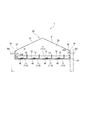
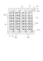
- FIG. 1 It is a perspective view which shows the atmospheric exposure test apparatus 1 which concerns on one Embodiment of this invention. It is a schematic diagram which shows the inside of the atmospheric exposure test apparatus 1 which concerns on the same embodiment. It is a top view which shows the state except a part of food
- FIG. 6 is a perspective view showing a ridge roof-shaped hood 20B that is a modification of the hood 20; It is a perspective view which shows the hood 20C of the single flow roof shape which is a modification of the hood 20.
- FIG. 6 is a perspective view showing a quadrangular pyramid-shaped hood 20D that is a modification of the hood 20; It is a perspective view which shows the cone-shaped food
- FIG. It is a perspective view which shows the hemispherical food
- FIG. 6 is a perspective view showing a semi-cylindrical hood 20H that is a modified example of the hood 20. It is a perspective view which shows the hood 20I of the shape which connected the quarter sphere (the shape of the quarter of a sphere) to the both ends of the half cylinder of FIG.
- FIG. 4 is a schematic view showing an aspect in which another test piece 50 is further attached to the test piece support unit 10. 6 is a side view showing a modified example of the test piece 40.
- FIG. It is sectional drawing which shows the aspect which supports a test piece horizontally with a pair of support girder 112 which mutually opposes.
- the atmospheric exposure test apparatus 1 is an apparatus for performing a shielding exposure test. As shown in FIGS. 1 to 3, a test piece support unit 10 that horizontally supports a test piece 40, and this test And a hood 20 that covers the upper surface of the single support unit 10.
- a test piece support unit 10 that horizontally supports a test piece 40, and this test And a hood 20 that covers the upper surface of the single support unit 10.
- an extremely thin material or an ultrafine material having a thickness or a diameter of 10 ⁇ m to 500 ⁇ m is used as the test piece 40, thereby evaluating the perforation of the ultrathin material and cutting the ultrafine material. It is also possible to perform evaluation or comparative evaluation with different materials installed at the same time.
- the material of the test piece 40 is not limited to iron, and other materials that cause corrosion problems such as other metals and concrete can be used.
- the hood 20 is formed in a gable roof shape. That is, the hood 20 has a pair of inclined surfaces 21, a side surface 22 that hangs down from the lower edge thereof, and an intersecting surface (wife surface) 23 that intersects the inclined surface 21 and the side surface 22. These inclined surface 21, side surface 22, and intersecting surface 23 are each formed of a steel plate, and surfaces are formed and joined by bending, welding, and rivets.
- the lower surface of the inclined surface 21 that overlaps the test piece 40 that is, the inner surface facing the test piece 40 has an inclination angle ⁇ of 30 degrees or more with respect to the horizontal plane.
- the column 22 is attached to the side surface 22 in the vicinity of both ends thereof.
- the support column 24 is formed of a steel pipe and is fixed to the side surface 22 by a U-shaped fixing bracket 241.
- the fixing bracket 241 has a pair of tips inserted into a pair of holes formed in the side surface 22 and protrudes to the inside of the side surface 22, and a nut 242 is screwed into each.
- the fixing bracket 241 tightens the column 24 to the side surface 22, thereby fixing the column 24.
- the tightening fixing position of the column 24, that is, the height position of the hood 20 can be changed.
- a fixed plate 25 is fixed to the lower end of the support column 24 by welding.
- the fixed plate 25 is formed of a steel plate, and fixed holes are formed at the four corners.
- the support column 24 is placed on the foundation by the fixing plate 25, and can be prevented from inadvertently moving even in a strong wind by tightening and fixing with a bolt or the like (not shown) embedded in the foundation.
- the test piece support unit 10 includes a frame 11, a connecting member 13, and a test piece fixing member 15.
- the frame 11 is formed by spanning a support girder 112 over a pair of main girders 111.
- the main girder 111 and the support girder 112 are each formed of a steel material having an L-shaped section or a C-shaped section.
- both ends of the main beam 111 are fixed to the inner surface of the side surface 22 of the hood 20.
- the frame 11 is held horizontally along the opening surface on the lower surface side of the hood 20, and the upper surface side thereof is covered with the hood 20.
- the support beam 112 has a lower surface portion 112A and an upper surface portion 112B that stands upright from the lower surface portion 112A, and has a predetermined interval in its extending direction (longitudinal direction).
- a plurality of connecting members 13 are attached.
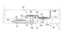
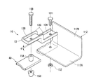
- the connecting member 13 is formed of a steel plate and has a crank-shaped side surface shape as shown in FIGS. More specifically, the connecting member 13 is connected to the lower step portion 13A connected by the bolt 131 and the nut 132 on the lower surface portion 112A of the support beam 112 of the frame 11, and is connected to the lower step portion 13A and more than the lower step portion 13A. And an upper step portion 13B disposed at a high position.
- the connecting member 13 is formed with an upright portion 13C that rises upward from the periphery of the lower step portion 13A and the upper step portion 13B except for the tip of the lower step portion 13A.
- the upper step portion 13B of the connecting member 13 is inclined by a slight inclination angle ⁇ with respect to the horizontal plane (or the lower step portion 13A), and the side away from the lower step portion 13A is formed high.
- a test piece 40 is supported on the lower surface side of the upper stage portion 13B via a test piece fixing member 15 extending in the vertical direction.
- the test piece fixing member 15 includes a spacer 15A, a bolt 15B, and a nut 15C.
- the spacer 15 ⁇ / b> A extends downward from the upper step portion 13 ⁇ / b> B of the connecting member 13 and horizontally supports the test piece 40 at a position lower than the support beam 112.
- the spacer 15A is a hollow cylindrical member, and the bolt 15B is inserted through the hole formed in the upper step portion 13B of the connecting member 13, the hollow portion of the spacer 15A, and the hole formed in the test piece 40, and the lower end of the bolt 15B. It is fixed by screwing the nut 15C into the nut.
- the test piece 40 includes a plastic plate-like base material 42 fixed by the test piece fixing member 15, and a thin plate (for example, 3 mm) of a test material attached to the front and back of the base material 42. ⁇ 5 mm).
- a plate material made of an insulating material which is hardly corroded such as vinyl chloride resin or FRP (fiber reinforced plastic) is used.
- the test piece 40 is held at a position where the surface of the test patch 41 on the lower surface side is substantially the same as the height of the opening surface on the lower surface side of the hood 20. Further, the surface of the test patch 41 on the upper surface side is held below the lower surface portion 112 ⁇ / b> A of the support beam 112.
- the atmospheric exposure test is performed by the following procedure. First, a test piece 40 having a test patch 41 for a desired test material is supported by the test piece support unit 10. Next, the atmospheric exposure test apparatus 1 to which the test piece 40 is attached is carried into the test place and installed in a state where the test piece 40 is erected by the support column 24. In this state, an air exposure test is performed over a predetermined period. When the test period ends, the air exposure test apparatus 1 is collected, transported to an analysis place, and analyzed.
- test piece 40 supported by the test piece support unit 10 is covered with the hood 20 and can be used as a shielding exposure test.
- the lower surface of the portion of the hood 20 that overlaps with the test piece 40 in plan view, that is, the inner surface facing the test piece 40 has an inclination angle ⁇ with respect to the horizontal plane of 30 degrees or more. For this reason, even if dew condensation occurs on the lower surface of the inclined surface 21 during the atmospheric exposure test, and the water droplet grows and reaches a size that drops, the water droplet flows down along the inclined lower surface.
- the inclination angle ⁇ with respect to the horizontal plane is 30 degrees or more, even when the distortion occurs during the manufacture of the hood 20, or when the deflection occurs due to its own weight or environmental change (temperature change) after the hood 20 is installed, Condensation generated on the lower surface of the hood 20 can be prevented from dripping as water droplets, and the influence of condensed moisture on the test piece 40 can be eliminated.
- the inclination angle ⁇ with respect to the horizontal plane is preferably 33 degrees or more, and more preferably 35 degrees or more.
- the inclination angle ⁇ of the lower surface of the hood 20 with respect to the horizontal plane may be 45 degrees or less.
- the entire lower surface side of the pair of inclined surfaces 21 can be inclined at 30 degrees or more with respect to the horizontal plane.
- the gable roof shape is a shape in which a pair of inclined surfaces 21 are joined by a central ridgeline, and can be a simple structure.
- the test piece 40 can be supported horizontally, and the surface of the test patch 41 on the lower surface side of the test piece 40 is disposed substantially the same as the height of the lower end of the hood 20, that is, the lower surface side opening surface. Can do.
- the test piece 40 of the present embodiment can be exposed to a rain and rain exposure environment similar to the lower flange of a bridge using H steel, and an exposure test environment closer to the actual can be obtained.
- the influence of the cross wind at the height position of the lower end of the hood 20 becomes smaller from the plan view end of the hood 20 toward the plan view central portion of the hood 20.
- the height position of the surface of the test patch 41 on the lower surface side of the test piece 40 disposed in the center of the hood 20 in plan view is the height of the lower end of the hood 20.
- the surface of the test patch 41 on the lower surface side of the test piece 40 is included in the region sandwiched between the surfaces having an inclination of ⁇ 6% or less.
- the test piece 40 is supported by the support beam 112 of the frame 11 via the connecting member 13 and the test piece fixing member 15. Therefore, the position of the test piece 40 can be appropriately selected regardless of the mechanical configuration of the frame 11 by appropriately adjusting the shape of the connecting member 13 or the test piece fixing member 15.
- the horizontally supported test piece 40 is supported at a position lower than the frame 11 so that the wind blown to the test piece 40 during the test can be directly received, and the hood 20 and the frame. 11 can be avoided. Therefore, an exposure test environment that is closer to reality can be obtained.
- the upper step portion 13B of the connecting member 13 that supports the horizontal test piece 40 is installed at a position higher than the lower step portion 13A connected to the frame 11. For this reason, even if water droplets due to condensation occur on the connecting member 13 or the frame 11, the water droplets can be prevented from flowing toward the test piece 40.
- the upright portion 13C is formed around the connection member 13, in addition to increasing the rigidity of the connection member 13, even if dew condensation occurs on the upper surface of the upper step portion 13B of the connection member 13, it falls to the test piece 40. Can be prevented, and can flow down to the lower side where the upright portion 13C is open.
- the upper stage portion 13B of the connecting member 13 is arranged with an inclination angle ⁇ with respect to the horizontal, it is possible to promote the outflow of water droplets to the lower stage portion 13A.
- the inclination angle ⁇ is preferably set to 5 degrees or more, and more preferably set to 7 degrees or more.
- the inclination angle ⁇ since the above effect is saturated even if the inclination angle ⁇ exceeds 20 degrees, the inclination angle ⁇ may be 20 degrees or less.
- the atmospheric exposure test apparatus 1 according to one embodiment of the present invention has been described above with reference to FIGS. 1 to 5.
- the present invention is not limited to the above-described embodiment, and the object of the present invention is Variations that can be achieved are included in the present invention.
- hood 20 is used, and the inclination
- a ridge roof-shaped hood 20B, a single-flow roof-shaped hood 20C, a quadrangular pyramid-shaped hood 20D, and a conical hood 20E as shown in FIGS. 6B to 6E may be used. .
- the gable roof shape is a shape in which a pair of inclined surfaces are joined by a central ridgeline, and the dormitory roof shape has a total of four inclined surfaces formed on each crossing surface of the gable roof shape described above. It is a shape having an inclined surface, and the single-flow roof shape is a shape composed of only one inclined surface.
- the hood 20B is formed in the shape of a roof, and the two pairs of inclined surfaces 21A and 21B each have an inclination angle of 30 degrees or more with respect to the horizontal surface on the lower surface side.
- the hood 20C is formed in a single-flow roof shape, and the single inclined surface 21C has an inclination angle of 30 degrees or more with respect to the horizontal surface on the lower surface side.
- the hood 20D is formed in a quadrangular pyramid shape, and each of the four inclined surfaces 21D has an inclination angle of 30 degrees or more with respect to the horizontal surface on the lower surface side.
- the hood 20E is formed in a conical shape, and the inclined surface 21E has an inclination angle of 30 degrees or more with respect to the horizontal surface on the lower surface side.
- FIG. 6F shows a hemispherical hood 20F.
- the inner surface 21F has an inclination angle of 30 degrees or more with respect to the horizontal plane, except for a partial region near the apex.
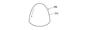
- FIG. 6G shows a hemispherical hood 20G stretched vertically.
- the inner side surface 21G has an inclination angle of 30 degrees or more with respect to the horizontal plane except for a partial region near the apex.
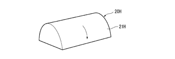
- FIG. 6H shows a semi-cylindrical hood 20H.
- the inner side surface 21H has an inclination angle of 30 degrees or more with respect to the horizontal plane except for a partial region near the top ridge line.
- FIG. 6I shows a hood 20I having a shape in which a quarter hemisphere (a quarter shape of a sphere) is connected to both ends of the half cylinder of FIG. 6H.
- the inner side surface 21I has an inclination angle of 30 degrees or more with respect to the horizontal plane except for a partial region near the top ridgeline.
- the hoods 20F to 20I include portions where the inclination angle with respect to the horizontal plane on the lower surface side of each hood is less than 30 degrees. Therefore, it is preferable not to install the test piece directly below the portion of the hood where the inclination angle with respect to the horizontal surface on the lower surface side is less than 30 degrees.
- the inclination angle ⁇ of the lower surface of the portion of the hood that overlaps with the test piece when viewed in plan may be 30 degrees or more.
- the inclination angle of the lower surface with respect to the horizontal plane means the angle formed with the tangential horizontal plane of each part of the hood.
- test piece 40 that is horizontally supported is attached to the test piece support unit 10 as shown in FIG.
- another test piece 50 installed in the vertical direction may be further attached to the test piece support unit 10. Similar to the test piece 40, the other test piece 50 is obtained by attaching a test patch, which is a thin plate of a test material, to the front and back of a plastic substrate. Even in such a configuration, it is possible to obtain the same effect as that of the above-described embodiment of FIG. 1 by adding the test result by the other test piece 50 installed in the vertical direction.
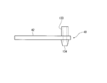
- the base material 42 itself may be formed of a test material and the test patch 41 may be omitted. Even in such a configuration, the exposure test can be performed on the surface of the base material 42 formed of the test material in the same manner as in the case where the atmospheric exposure test apparatus 1 according to the embodiment of FIG. 1 described above is used.
- the single hood 20 is used.
- another cover that covers the outside of the hood 20 may be further installed, or may be duplicated, or around the hood 20.
- Another fence or the like may be installed to adjust the crosswind.
- test piece fixing member 15 is used as a separate member from the connecting member 13 and the test piece 40. It may be formed integrally with the test piece 40.
- FIG. 9 shows another embodiment of the present invention.
- the test piece fixing member 15 and the connecting member 13 are connected to one end of the test piece 40 and supported by the support beam 112, and the test piece 40 is a so-called cantilever lever. It was in a state. For this reason, the cantilever lever may vibrate due to strong winds.
- the test piece 40 is horizontally supported by the test piece support unit 10 ⁇ / b> A having the pair of support girders 112 provided facing each other, that is, By supporting the test piece 40 across the pair of frames 11, the possibility of vibration as described above can be greatly reduced.
- two support girders 112 are installed back-to-back so that the upper surface portions 112B of the support girders 112 face each other, and the lower surface portions 112A of the support girders 112 project on both sides. And between the adjacent support girders 112, the lower surface portions 112A are arranged to face each other.
- test piece fixing member 15 is provided on the facing lower surface portion 112 ⁇ / b> A via the connecting member 13, and the test piece 40 is horizontally supported between the pair of test piece fixing members 15.
- the test piece 40 is configured so that the test piece fixing member 15 can be connected to both ends of the base material 42.
- Test patches 41 are attached to the front and back surfaces of the base material 42, respectively.
- the same effects as those of the embodiment of FIG. 1 described above can be obtained, and the following effects can be obtained. That is, in this embodiment, the test piece 40 is supported by the pair of support girders 112 at both ends. For this reason, for example, rocking hardly occurs as in the case of being supported in a cantilever state, and the influence on the test result due to vibration or the like can be avoided even when exposed to a strong wind.
- an atmospheric exposure test apparatus that can be used for a shielding exposure test of steel materials used for structures such as bridges.
- Test piece support unit 11 Frame 111: Main beam 112: Support beam 112A: Lower surface portion 112B: Upper surface portion 13: Connecting member 13A: Lower step portion 13B: Upper step portion 13C: Standing portion 131 : Bolt 132: Nut 15: Test piece fixing member 15A: Spacer 15B: Bolt 15C: Nut 20, 20B to 20I: Hood 21, 21A to 21I: Inclined surface 22: Side surface 23: Crossing surface (wife surface) 24: support 241: fixing bracket 242: nut 25: fixing plate 40: test piece 41: test patch 42: base material 50: other test piece ⁇ : inclination angle of the upper step of the connecting member ⁇ : inclination of the lower surface of the hood angle
Landscapes
- Life Sciences & Earth Sciences (AREA)
- Biodiversity & Conservation Biology (AREA)
- Ecology (AREA)
- Environmental & Geological Engineering (AREA)
- Environmental Sciences (AREA)
- Physics & Mathematics (AREA)
- Health & Medical Sciences (AREA)
- Chemical & Material Sciences (AREA)
- Analytical Chemistry (AREA)
- Biochemistry (AREA)
- General Health & Medical Sciences (AREA)
- General Physics & Mathematics (AREA)
- Immunology (AREA)
- Pathology (AREA)
- Testing Resistance To Weather, Investigating Materials By Mechanical Methods (AREA)
Abstract
この大気曝露試験装置は、試験片を水平に支持する試験片支持ユニットと、前記試験片支持ユニットの上面を覆うフードと、を備え、前記試験片支持ユニットは、支持桁を有するフレームと、前記支持桁に連結される下段部、及び、前記下段部に接続されて前記下段部よりも高い位置に配置される上段部を有する連結部材と、前記上段部から下方に延出し、前記支持桁よりも低い位置で前記試験片を水平に支持する試験片固定部材と、を備え、前記フードの下端部の高さ位置が、前記試験片の下端部の高さ位置と略同一であり、前記フードの、平面視した場合に前記試験片と重なる部位の下面の水平面に対する傾斜角度θが30度以上である。
Description
本発明は、遮蔽曝露試験に利用できる大気曝露試験装置に関する。
本願は、2014年4月7日に、日本に出願された特願2014-078712号に基づき優先権を主張し、その内容をここに援用する。
本願は、2014年4月7日に、日本に出願された特願2014-078712号に基づき優先権を主張し、その内容をここに援用する。
橋梁その他の鉄鋼構造物においては、開放大気環境下での耐候性・耐食性を考慮することが要求される。
これらの耐候性・耐食性の評価には、日本工業規格JISZ2381「大気暴露試験方法通則」(非特許文献1)が利用される。
これらの耐候性・耐食性の評価には、日本工業規格JISZ2381「大気暴露試験方法通則」(非特許文献1)が利用される。
橋梁などの構造物では、外面が太陽光や風雨に曝されるため、前述した規格のなかでも「直接曝露試験」による評価を行うことが好ましい。一方、橋桁の下面側や内側は太陽光や風雨に曝されにくく、構造物表面の残留塩分等が耐候性に影響する。従って、これらの残留塩分等を流失させる風雨などの影響を避けられる「遮蔽曝露試験」による評価を行うことが好ましい。
遮蔽曝露試験には、試験材料である被検体を、所期の遮蔽性能を有する曝露容器あるいは曝露架台に収容した大気曝露試験装置が用いられる。
例えば、被検体として試験材料を小型の矩形板状に形成したワッペンを用い、曝露容器として百葉箱に類似の筐体を用い、通気は得るようにしつつ風雨の影響を避けるようにした構造が知られている(非特許文献2)。
例えば、被検体として試験材料を小型の矩形板状に形成したワッペンを用い、曝露容器として百葉箱に類似の筐体を用い、通気は得るようにしつつ風雨の影響を避けるようにした構造が知られている(非特許文献2)。
日本工業規格JISZ2381:2001「大気暴露試験方法通則」、一般財団法人日本規格協会
「耐候性鋼橋梁の適用性評価と防食予防安全」42頁‐43頁、平成21年9月、社団法人日本鋼構造協会
前述した遮蔽曝露試験では、風雨の影響を避けるような曝露容器などを用いている。しかし、気候条件によっては、曝露容器の内側に結露が生じ、この結露水分が滴下して被検体にかかる可能性がある。
このような水分滴下により、被検体の表面の付着塩分等が流失すると、適切な試験結果が得られない可能性がでてくる。さらに、水分滴下が特定の部位に限られる場合など、周囲の他の被検体との比較結果が適切でなくなる可能性がある。
このような水分滴下により、被検体の表面の付着塩分等が流失すると、適切な試験結果が得られない可能性がでてくる。さらに、水分滴下が特定の部位に限られる場合など、周囲の他の被検体との比較結果が適切でなくなる可能性がある。
さらに、橋梁などの構造物では、特にその下面側や内側での風の影響を考慮する必要があるが、前述した従来の曝露容器では、橋梁などの構造物に相当する環境が再現できていなかった。このため、橋梁などの構造物における風の影響をも評価できるような、曝露試験としての性能向上が望まれていた。
本発明の目的は、結露水分の影響を解消することができるとともに、より実際に近い曝露試験環境が得られる大気曝露試験装置を提供することにある。
本発明は以下の構成を採用する。
(1)本発明の一態様に係る大気曝露試験装置は、試験片を水平に支持する試験片支持ユニットと、前記試験片支持ユニットの上面を覆うフードと、を備え、前記試験片支持ユニットは、支持桁を有するフレームと、前記支持桁に連結される下段部、及び、前記下段部に接続されて前記下段部よりも高い位置に配置される上段部を有する連結部材と、前記上段部から下方に延出し、前記支持桁よりも低い位置で前記試験片を水平に支持する試験片固定部材と、を備え、前記フードの下端部の高さ位置が、前記試験片の下端部の高さ位置と略同一であり、前記フードの、平面視した場合に前記試験片と重なる部位の下面の水平面に対する傾斜角度θが30度以上である。
(2)上記(1)に係る大気曝露試験装置では、前記連結部材の前記上段部の下面の水平面に対する傾斜角度αが5度以上20度以下であってもよい。
(3)上記(1)又は(2)に係る大気曝露試験装置では、前記連結部材が、前記上段部及び前記下段部の周縁の少なくとも一部から起立する起立部を有してもよい。
(4)上記(1)~(3)のいずれか一項に係る大気曝露試験装置では、前記フレームが、互いに対向して設けられる一対の前記支持桁を有するとともに、それぞれの前記支持桁に前記連結部材を介して前記試験片固定部材が接続され、前記試験片が、前記一対の試験片固定部材により水平に支持されてもよい。
(5)上記(1)~(4)のいずれか一項に係る大気曝露試験装置では、前記傾斜角度θが45度以下であってもよい。
(6)上記(1)~(5)のいずれか一項に係る大気曝露試験装置では、前記フードは、円錐状、角錐状、寄棟屋根状、切妻屋根状、片流れ屋根状の何れか一種であってもよい。
(1)本発明の一態様に係る大気曝露試験装置は、試験片を水平に支持する試験片支持ユニットと、前記試験片支持ユニットの上面を覆うフードと、を備え、前記試験片支持ユニットは、支持桁を有するフレームと、前記支持桁に連結される下段部、及び、前記下段部に接続されて前記下段部よりも高い位置に配置される上段部を有する連結部材と、前記上段部から下方に延出し、前記支持桁よりも低い位置で前記試験片を水平に支持する試験片固定部材と、を備え、前記フードの下端部の高さ位置が、前記試験片の下端部の高さ位置と略同一であり、前記フードの、平面視した場合に前記試験片と重なる部位の下面の水平面に対する傾斜角度θが30度以上である。
(2)上記(1)に係る大気曝露試験装置では、前記連結部材の前記上段部の下面の水平面に対する傾斜角度αが5度以上20度以下であってもよい。
(3)上記(1)又は(2)に係る大気曝露試験装置では、前記連結部材が、前記上段部及び前記下段部の周縁の少なくとも一部から起立する起立部を有してもよい。
(4)上記(1)~(3)のいずれか一項に係る大気曝露試験装置では、前記フレームが、互いに対向して設けられる一対の前記支持桁を有するとともに、それぞれの前記支持桁に前記連結部材を介して前記試験片固定部材が接続され、前記試験片が、前記一対の試験片固定部材により水平に支持されてもよい。
(5)上記(1)~(4)のいずれか一項に係る大気曝露試験装置では、前記傾斜角度θが45度以下であってもよい。
(6)上記(1)~(5)のいずれか一項に係る大気曝露試験装置では、前記フードは、円錐状、角錐状、寄棟屋根状、切妻屋根状、片流れ屋根状の何れか一種であってもよい。
本発明の上記態様に係る大気曝露試験装置によれば、結露水分の影響を解消することができるとともに、より実際に近い曝露試験環境を得ることもできる。
以下、本発明の一実施形態に係る大気曝露試験装置1について図面に基づいて説明する。
本実施形態に係る大気曝露試験装置1は遮蔽曝露試験を行うための装置であり、図1~図3に示されるように、試験片40を水平に支持する試験片支持ユニット10と、この試験片支持ユニット10の上面を覆うフード20と、を備えて構成される。
尚、この大気曝露試験装置1では、試験片40として、例えば10μm~500μmの厚さまたは直径を有する極薄材料または極細材料を用いることで、極薄材料の穴あきの評価、極細材料の切断の評価、或いは同時に設置された異なる材料との比較評価を行うことも可能である。また、試験片40の素材も鉄に限らず他の金属やコンクリートなど腐食が問題となる素材を利用できる。
本実施形態に係る大気曝露試験装置1は遮蔽曝露試験を行うための装置であり、図1~図3に示されるように、試験片40を水平に支持する試験片支持ユニット10と、この試験片支持ユニット10の上面を覆うフード20と、を備えて構成される。
尚、この大気曝露試験装置1では、試験片40として、例えば10μm~500μmの厚さまたは直径を有する極薄材料または極細材料を用いることで、極薄材料の穴あきの評価、極細材料の切断の評価、或いは同時に設置された異なる材料との比較評価を行うことも可能である。また、試験片40の素材も鉄に限らず他の金属やコンクリートなど腐食が問題となる素材を利用できる。
フード20は、図1に示すように、切妻屋根状に形成されている。すなわち、フード20は、一対の傾斜面21と、その下縁から垂下する側面22と、傾斜面21と側面22に交差する交差面(妻面)23とを有する。
これらの傾斜面21、側面22、および交差面23は、それぞれ鋼板で形成され、折り曲げ加工、溶接、リベットで面が形成され接合されている。
フード20のうち、平面視した場合に試験片40と重なる部位の傾斜面21の下面、すなわち、試験片40に向き合う内側面は、水平面に対する傾斜角度θが30度以上とされている。
これらの傾斜面21、側面22、および交差面23は、それぞれ鋼板で形成され、折り曲げ加工、溶接、リベットで面が形成され接合されている。
フード20のうち、平面視した場合に試験片40と重なる部位の傾斜面21の下面、すなわち、試験片40に向き合う内側面は、水平面に対する傾斜角度θが30度以上とされている。
側面22には、その両端近傍に支柱24が取り付けられている。支柱24は、鋼管で形成され、U字状の固定金具241で側面22に固定されている。固定金具241は、一対の先端が側面22に形成された一対の孔に挿入され、側面22の内側に突出されており、各々にはナット242が螺合されている。
従って、側面22の内側でナット242を締め付けることで、固定金具241が支柱24を側面22に締め付け、これにより支柱24の固定が行われる。なお、ナット242を緩めることで、支柱24の締め付け固定位置つまりフード20の高さ位置を変更可能である。
支柱24の下端には固定板25が溶接で固定されている。固定板25は、鋼板で形成され、四隅に固定孔が形成されている。支柱24は、この固定板25により基礎上に載置されるとともに、基礎に埋設されたボルト等(図示省略)で締め付け固定すれば、強風時にも不用意に移動することを防止できる。
図2~図5に示すように、試験片支持ユニット10は、フレーム11と、連結部材13と、試験片固定部材15とにより構成される。
フレーム11は、一対の主桁111に支持桁112を掛け渡して形成されている。主桁111および支持桁112は、それぞれ断面L字状あるいはC字状の鋼材で形成されている。図1~図3に示すように、主桁111の両端は、フード20の側面22の内側面に固定されている。これにより、フレーム11は、フード20の下面側の開口面に沿って水平に保持され、その上面側がフード20によって覆われている。
支持桁112は、図3~図5に示すように、下面部112Aと、下面部112Aから垂直に起立する上面部112Bとを有し、その延在方向(長手方向)に所定間隔を空けて複数の連結部材13が取り付けられる。
連結部材13は鋼板で形成され、図4、図5に示すようにクランク状の側面形状を有する。より詳細には、連結部材13は、フレーム11の支持桁112の下面部112Aの上にボルト131及びナット132により連結される下段部13Aと、下段部13Aに接続されるとともに下段部13Aよりも高い位置に配置される上段部13Bとを有する。
本実施形態においては、連結部材13は、その下段部13Aの先端を除いて、下段部13A及び上段部13Bの周縁から上方に向けて起立する起立部13Cが形成されている。また、連結部材13の上段部13Bは、水平面(又は下段部13A)に対して僅かな傾斜角度αだけ傾斜し、下段部13Aから離れた側が高く形成されている。
本実施形態においては、連結部材13は、その下段部13Aの先端を除いて、下段部13A及び上段部13Bの周縁から上方に向けて起立する起立部13Cが形成されている。また、連結部材13の上段部13Bは、水平面(又は下段部13A)に対して僅かな傾斜角度αだけ傾斜し、下段部13Aから離れた側が高く形成されている。
上段部13Bの下面側には、鉛直方向に延在する試験片固定部材15を介して試験片40が支持されている。
試験片固定部材15は、スペーサー15Aと、ボルト15Bと、ナット15Cにより構成される。
スペーサー15Aは、連結部材13の上段部13Bから下方に延出し、支持桁112よりも低い位置で試験片40を水平に支持する。
スペーサー15Aは中空円筒状の部材であり、連結部材13の上段部13Bに形成された孔、スペーサー15Aの中空部、及び試験片40に形成された孔にボルト15Bを挿通し、ボルト15Bの下端にナット15Cを螺合することにより固定される。
試験片固定部材15は、スペーサー15Aと、ボルト15Bと、ナット15Cにより構成される。
スペーサー15Aは、連結部材13の上段部13Bから下方に延出し、支持桁112よりも低い位置で試験片40を水平に支持する。
スペーサー15Aは中空円筒状の部材であり、連結部材13の上段部13Bに形成された孔、スペーサー15Aの中空部、及び試験片40に形成された孔にボルト15Bを挿通し、ボルト15Bの下端にナット15Cを螺合することにより固定される。
試験片40は、図4に示すように、試験片固定部材15により固定されるプラスチック製の板状の基材42と、基材42の表裏に貼られた、被検材の薄板(例えば3mm~5mm)である試験用ワッペン41とにより構成される。
基材42としては、例えば、塩化ビニル樹脂やFRP(繊維強化プラスチック)等の腐蝕しにくく、かつ絶縁性の材料で形成された板材が用いられる。
基材42としては、例えば、塩化ビニル樹脂やFRP(繊維強化プラスチック)等の腐蝕しにくく、かつ絶縁性の材料で形成された板材が用いられる。
試験片40は、図4に示す通り、下面側の試験用ワッペン41の表面が、フード20の下面側開口面の高さと略同一である位置に保持されている。また、上面側の試験用ワッペン41の表面は、支持桁112の下面部112Aより下方に保持されている。
このような本実施形態においては、次の手順で大気曝露試験を実施する。
先ず、所期の被検材の試験用ワッペン41を有する試験片40を、試験片支持ユニット10により支持する。次に、試験片40が装着された大気曝露試験装置1を、試験場所に搬入し、支柱24で起立させた状態で設置する。
この状態で、所期の期間にわたり、大気曝露試験を行い、試験期間が終了したら、大気曝露試験装置1を回収し、分析場所に搬送し、分析を行う。
先ず、所期の被検材の試験用ワッペン41を有する試験片40を、試験片支持ユニット10により支持する。次に、試験片40が装着された大気曝露試験装置1を、試験場所に搬入し、支柱24で起立させた状態で設置する。
この状態で、所期の期間にわたり、大気曝露試験を行い、試験期間が終了したら、大気曝露試験装置1を回収し、分析場所に搬送し、分析を行う。
このような本実施形態では、次のような効果がある。
試験片支持ユニット10により支持された試験片40は、フード20により覆われて遮蔽曝露試験とすることができる。
この際、フード20のうち、平面視した場合に試験片40と重なる部位の下面、つまり試験片40に向き合う内側面は、水平面に対する傾斜角度θが30度以上とされている。このため、大気曝露試験の際に傾斜面21の下面に結露が生じ、水滴が成長して滴下する程度の大きさに至ったとしても、この水滴は傾斜した下面を伝って下方へ流下する。従って、フード20の下面に結露を生じても、水滴として滴下することを防止でき、試験片40に対する結露水分の影響を解消することができる。
また、水平面に対する傾斜角度θが30度以上であれば、フード20の製造時に発生する歪みや、フード20の設置後の自重又は環境変化(温度変化)によって撓みが発生した場合であっても、フード20の下面に生じる結露が水滴として滴下することを防止でき、試験片40に対する結露水分の影響を解消することができる。
水平面に対する傾斜角度θは33度以上であれば好ましく、35度以上であれば更に好ましい。
一方、水平面に対する傾斜角度θが45度を超えても上記の効果は飽和し、製作コストが必要以上に上昇する。従って、フード20の下面の水平面に対する傾斜角度θは45度以下としてもよい。
試験片支持ユニット10により支持された試験片40は、フード20により覆われて遮蔽曝露試験とすることができる。
この際、フード20のうち、平面視した場合に試験片40と重なる部位の下面、つまり試験片40に向き合う内側面は、水平面に対する傾斜角度θが30度以上とされている。このため、大気曝露試験の際に傾斜面21の下面に結露が生じ、水滴が成長して滴下する程度の大きさに至ったとしても、この水滴は傾斜した下面を伝って下方へ流下する。従って、フード20の下面に結露を生じても、水滴として滴下することを防止でき、試験片40に対する結露水分の影響を解消することができる。
また、水平面に対する傾斜角度θが30度以上であれば、フード20の製造時に発生する歪みや、フード20の設置後の自重又は環境変化(温度変化)によって撓みが発生した場合であっても、フード20の下面に生じる結露が水滴として滴下することを防止でき、試験片40に対する結露水分の影響を解消することができる。
水平面に対する傾斜角度θは33度以上であれば好ましく、35度以上であれば更に好ましい。
一方、水平面に対する傾斜角度θが45度を超えても上記の効果は飽和し、製作コストが必要以上に上昇する。従って、フード20の下面の水平面に対する傾斜角度θは45度以下としてもよい。
本実施形態では、フード20を切妻屋根状としたため、一対の傾斜面21の下面側の全体を、水平面に対して傾斜を30度以上とすることができる。また、切妻屋根状は、一対の傾斜面21が、中央の棟線で接合された形状であり、簡単な構造とすることができる。
本実施形態では、試験片40を水平に支持することができ、試験片40の下面側の試験用ワッペン41の表面を、フード20の下端つまり下面側開口面の高さと略同一に配置することができる。このような配置により、本実施形態の試験片40は、H鋼を用いた橋梁の下フランジと同様な風雨曝露環境とすることができ、より実際に近い曝露試験環境を得ることができる。
尚、フード20の下端部の高さ位置における横風の影響は、フード20の平面視端部からフード20の平面視中央部に向かうほど小さくなる。例えばフード20の平面寸法が1000mm×1000mmの場合、フード20の平面視中央部に配置される試験片40の下面側の試験用ワッペン41の表面の高さ位置は、フード20の下端部の高さ位置よりも±30mm程度までなら高低差があってもよい。従って、「フード20の下端部の高さ位置が、試験片40の高さ位置と略同一」とは、厳密には、フード20の下端部を含む水平面に対し、フード20の下端部を基準として±6%以下の傾斜勾配を有する面で挟まれる領域に、試験片40の下面側の試験用ワッペン41の表面が含まれる形態であればよい。
尚、フード20の下端部の高さ位置における横風の影響は、フード20の平面視端部からフード20の平面視中央部に向かうほど小さくなる。例えばフード20の平面寸法が1000mm×1000mmの場合、フード20の平面視中央部に配置される試験片40の下面側の試験用ワッペン41の表面の高さ位置は、フード20の下端部の高さ位置よりも±30mm程度までなら高低差があってもよい。従って、「フード20の下端部の高さ位置が、試験片40の高さ位置と略同一」とは、厳密には、フード20の下端部を含む水平面に対し、フード20の下端部を基準として±6%以下の傾斜勾配を有する面で挟まれる領域に、試験片40の下面側の試験用ワッペン41の表面が含まれる形態であればよい。
本実施形態において、試験片40は、連結部材13及び試験片固定部材15を介してフレーム11の支持桁112に支持されている。従って、連結部材13又は試験片固定部材15の形状を適宜調整することで、フレーム11の機械的構成に拘わらず、試験片40の位置を適切に選択することができる。
とくに、本実施形態では、水平に支持される試験片40を、フレーム11よりも低い位置に支持することで、試験中に試験片40に吹き付けられる風を直接受けることができ、フード20およびフレーム11による風の乱れ等を回避することができる。従って、より実際に近い曝露試験環境を得ることができる。
とくに、本実施形態では、水平に支持される試験片40を、フレーム11よりも低い位置に支持することで、試験中に試験片40に吹き付けられる風を直接受けることができ、フード20およびフレーム11による風の乱れ等を回避することができる。従って、より実際に近い曝露試験環境を得ることができる。
本発実施形態において、水平な試験片40を支持する連結部材13の上段部13Bは、フレーム11に接続される下段部13Aよりも高い位置に設置されている。このため、結露による水滴が連結部材13又はフレーム11に生じても、この水滴が試験片40側に流れることを防止できる。
とくに、連結部材13において、周囲に起立部13Cが形成される場合、連結部材13の剛性を高めることに加え、連結部材13の上段部13Bの上面に結露が生じても、試験片40に落下することを防止でき、起立部13Cが開いている下段側へと専ら流下させることができる。
さらに、連結部材13の上段部13Bが水平に対する傾斜角度αを有して配置される場合、下段部13Aへの水滴の流出を促進することができる。この効果を得るためには、傾斜角度αを5度以上に設定することが好ましく、7度以上に設定することが更に好ましい。一方、傾斜角度αが20度を超えても上記の効果は飽和するため、傾斜角度αは20度以下としてもよい。
さらに、連結部材13の上段部13Bが水平に対する傾斜角度αを有して配置される場合、下段部13Aへの水滴の流出を促進することができる。この効果を得るためには、傾斜角度αを5度以上に設定することが好ましく、7度以上に設定することが更に好ましい。一方、傾斜角度αが20度を超えても上記の効果は飽和するため、傾斜角度αは20度以下としてもよい。
以上、図1~図5を参照して本発明の一実施形態に係る大気曝露試験装置1を説明したが、本発明は前述した実施形態のみに限定されるものではなく、本発明の目的を達成できる範囲での変形などは本発明に含まれる。
図6Aに示すように、前述した実施形態に係る大気曝露試験装置1では切妻屋根状のフード20を用い、一対の傾斜面21の下面側の水平面に対する傾斜角度を30度以上としている。これに対し、本発明においては、図6B~図6Eに示すような寄せ棟屋根状のフード20B、片流れ屋根状のフード20C、四角錐状のフード20D、円錐状のフード20Eを用いてもよい。
尚、切妻屋根状とは一対の傾斜面が中央の棟線で接合された形状であり、寄棟屋根状とは前述した切妻屋根状の各交差面にも傾斜面が形成されて合計四つの傾斜面を有する形状であり、片流れ屋根状とは一つの傾斜面だけで構成される形状である。
尚、切妻屋根状とは一対の傾斜面が中央の棟線で接合された形状であり、寄棟屋根状とは前述した切妻屋根状の各交差面にも傾斜面が形成されて合計四つの傾斜面を有する形状であり、片流れ屋根状とは一つの傾斜面だけで構成される形状である。
図6Bにおいて、フード20Bは寄せ棟屋根状に形成され、二対の傾斜面21A、21Bは、それぞれ下面側の水平面に対する傾斜角度を30度以上としている。
図6Cにおいて、フード20Cは片流れ屋根状に形成され、単一の傾斜面21Cは、その下面側の水平面に対する傾斜角度を30度以上としている。
図6Dにおいて、フード20Dは四角錐状に形成され、4つの傾斜面21Dは、それぞれ下面側の水平面に対する傾斜角度を30度以上としている。
図6Eにおいて、フード20Eは円錐状に形成され、その傾斜面21Eは、下面側の水平面に対する傾斜角度を30度以上としている。
図6Cにおいて、フード20Cは片流れ屋根状に形成され、単一の傾斜面21Cは、その下面側の水平面に対する傾斜角度を30度以上としている。
図6Dにおいて、フード20Dは四角錐状に形成され、4つの傾斜面21Dは、それぞれ下面側の水平面に対する傾斜角度を30度以上としている。
図6Eにおいて、フード20Eは円錐状に形成され、その傾斜面21Eは、下面側の水平面に対する傾斜角度を30度以上としている。
更には、本発明においては、図6F~図6Iに示す変形例のフード20F~20Iを用いてもよい。
図6Fは、半球状のフード20Fを示す。その内側面21Fは、頂点近くの一部領域を除き、水平面に対して傾斜角度30度以上とされている。
図6Gは、縦に引き伸ばした半球状のフード20Gを示す。その内側面21Gは、頂点近くの一部領域を除き、水平面に対して傾斜角度30度以上とされている。
図6Hは、半円筒形状のフード20Hを示す。その内側面21Hは、頂上稜線近くの一部領域を除き、水平面に対して傾斜角度30度以上とされている。
図6Iは、図6Hの半円筒の両端に、四半球(球の四分の一の形状)を接続した形状のフード20Iを示す。その内側面21Iは、頂上稜線近くの一部領域を除き、水平面に対して傾斜角度30度以上とされている。
図6Fは、半球状のフード20Fを示す。その内側面21Fは、頂点近くの一部領域を除き、水平面に対して傾斜角度30度以上とされている。
図6Gは、縦に引き伸ばした半球状のフード20Gを示す。その内側面21Gは、頂点近くの一部領域を除き、水平面に対して傾斜角度30度以上とされている。
図6Hは、半円筒形状のフード20Hを示す。その内側面21Hは、頂上稜線近くの一部領域を除き、水平面に対して傾斜角度30度以上とされている。
図6Iは、図6Hの半円筒の両端に、四半球(球の四分の一の形状)を接続した形状のフード20Iを示す。その内側面21Iは、頂上稜線近くの一部領域を除き、水平面に対して傾斜角度30度以上とされている。
上記変形例のフード20F~20Iでは、各フードの下面側の水平面に対する傾斜角度が30度未満の部位を含む。従って、フードの部位のうち、下面側の水平面に対する傾斜角度が30度未満の部位の直下には、試験片を設置しないことが好ましい。
換言すると、フードのうち、平面視した場合に試験片と重なる部位の下面の水平面に対する傾斜角度θが30度以上であればよい。
尚、図6F~図6Iに示す変形例のように曲面を含むフードの場合、下面の水平面に対する傾斜角度は、フードの各部位の接線の水平面となす角度を意味する。
換言すると、フードのうち、平面視した場合に試験片と重なる部位の下面の水平面に対する傾斜角度θが30度以上であればよい。
尚、図6F~図6Iに示す変形例のように曲面を含むフードの場合、下面の水平面に対する傾斜角度は、フードの各部位の接線の水平面となす角度を意味する。
前述した実施形態に係る大気曝露試験装置1では、図4に示すように、水平に支持される試験片40のみが試験片支持ユニット10に取り付けられる。
これに対し、図7に示すように、水平に支持される試験片40に加え、鉛直方向に設置される他の試験片50を試験片支持ユニット10に更に取り付けてもよい。他の試験片50は、試験片40と同様に、プラスチック製の基材の表裏に、被検材の薄板である試験用ワッペンを貼ったものである。
このような構成でも、鉛直方向に設置される他の試験片50による試験結果を加えて、前述した図1の実施形態と同様な効果を得ることができる。
これに対し、図7に示すように、水平に支持される試験片40に加え、鉛直方向に設置される他の試験片50を試験片支持ユニット10に更に取り付けてもよい。他の試験片50は、試験片40と同様に、プラスチック製の基材の表裏に、被検材の薄板である試験用ワッペンを貼ったものである。
このような構成でも、鉛直方向に設置される他の試験片50による試験結果を加えて、前述した図1の実施形態と同様な効果を得ることができる。
また、前述した実施形態に係る大気曝露試験装置1では、図4に示すように、試験片40として、基材42に試験用ワッペン41を貼ったものを用いた。これに対し、本発明においては、図8に示すように、基材42自体を被検材で形成し、試験用ワッペン41を省略してもよい。
このような構成でも、被検材で形成された基材42の表面において、前述した図1の実施形態に係る大気曝露試験装置1を用いた場合と同様に曝露試験を行うことができる。
このような構成でも、被検材で形成された基材42の表面において、前述した図1の実施形態に係る大気曝露試験装置1を用いた場合と同様に曝露試験を行うことができる。
さらに、前述した実施形態に係る大気曝露試験装置1では、単独のフード20を用いたが、更にフード20の外側を覆う別のカバーを設置して二重化してもよく、あるいはフード20の周囲に別のフェンス等を設置して横風を調節するようにしてもよい。
さらに、前述した実施形態に係る大気曝露試験装置1では、試験片固定部材15を連結部材13及び試験片40とは別個の部材として利用しているが、試験片固定部材15は連結部材13又は試験片40と一体に形成されてもよい。
図9には、本発明の他の実施形態が示されている。
前述した実施形態に係る大気曝露試験装置1では、試験片40の一端に試験片固定部材15及び連結部材13を接続して支持桁112に支持しており、試験片40はいわゆる片持ちレバーの状態であった。このため、強風により片持ちレバーが振動する可能性があった。
これに対し、図9に示す実施形態では、試験片40を、互いに対向して設けられた一対の支持桁112を有する試験片支持ユニット10Aが試験片40を水平に支持することで、すなわち、試験片40を一対のフレーム11に掛け渡して支持することで、前述のような振動の可能性を大幅に低減することができる。
前述した実施形態に係る大気曝露試験装置1では、試験片40の一端に試験片固定部材15及び連結部材13を接続して支持桁112に支持しており、試験片40はいわゆる片持ちレバーの状態であった。このため、強風により片持ちレバーが振動する可能性があった。
これに対し、図9に示す実施形態では、試験片40を、互いに対向して設けられた一対の支持桁112を有する試験片支持ユニット10Aが試験片40を水平に支持することで、すなわち、試験片40を一対のフレーム11に掛け渡して支持することで、前述のような振動の可能性を大幅に低減することができる。
図9において、試験片支持ユニット10Aは、支持桁112の上面部112Bが互いに向かい合うように、支持桁112が2本ずつ背中合わせで設置され、支持桁112の下面部112Aは両側に張り出している。そして、隣接する支持桁112との間で、互いの下面部112Aが向かい合わせで配置されている。
向かい合う下面部112Aには、それぞれ連結部材13を介して試験片固定部材15が設けられ、これら一対の試験片固定部材15の間に試験片40が水平に支持されている。
試験片40は、基材42の両端に試験片固定部材15が接続できるように構成されている。基材42の表裏には、それぞれ試験用ワッペン41が貼られている。
試験片40は、基材42の両端に試験片固定部材15が接続できるように構成されている。基材42の表裏には、それぞれ試験用ワッペン41が貼られている。
このような本実施形態では、前述した図1の実施形態と同様な効果が得られるとともに、次のような効果が得られる。
すなわち、本実施形態では、試験片40が両端を一対の支持桁112で支持される。このため、例えば片持ちレバー状態で支持された場合のように揺動が生じにくく、強風に曝された場合でも振動などによる試験結果への影響を回避することができる。
すなわち、本実施形態では、試験片40が両端を一対の支持桁112で支持される。このため、例えば片持ちレバー状態で支持された場合のように揺動が生じにくく、強風に曝された場合でも振動などによる試験結果への影響を回避することができる。
本発明によれば、橋梁などの構造物に使用される鋼材などの遮蔽曝露試験に利用できる大気曝露試験装置を提供することができる。
1:大気曝露試験装置
10、10A:試験片支持ユニット
11:フレーム
111:主桁
112:支持桁
112A:下面部
112B:上面部
13:連結部材
13A:下段部
13B:上段部
13C:起立部
131:ボルト
132:ナット
15:試験片固定部材
15A:スペーサー
15B:ボルト
15C:ナット
20、20B~20I:フード
21、21A~21I:傾斜面
22:側面
23:交差面(妻面)
24:支柱
241:固定金具
242:ナット
25:固定板
40:試験片
41:試験用ワッペン
42:基材
50:他の試験片
α:連結部材の上段部の傾斜角度
θ:フードの下面の傾斜角度
10、10A:試験片支持ユニット
11:フレーム
111:主桁
112:支持桁
112A:下面部
112B:上面部
13:連結部材
13A:下段部
13B:上段部
13C:起立部
131:ボルト
132:ナット
15:試験片固定部材
15A:スペーサー
15B:ボルト
15C:ナット
20、20B~20I:フード
21、21A~21I:傾斜面
22:側面
23:交差面(妻面)
24:支柱
241:固定金具
242:ナット
25:固定板
40:試験片
41:試験用ワッペン
42:基材
50:他の試験片
α:連結部材の上段部の傾斜角度
θ:フードの下面の傾斜角度
Claims (6)
- 試験片を水平に支持する試験片支持ユニットと、
前記試験片支持ユニットの上面を覆うフードと、
を備え、
前記試験片支持ユニットは、
支持桁を有するフレームと、
前記支持桁に連結される下段部、及び、前記下段部に接続されて前記下段部よりも高い位置に配置される上段部を有する連結部材と、
前記上段部から下方に延出し、前記支持桁よりも低い位置で前記試験片を水平に支持する試験片固定部材と、
を備え、
前記フードの下端部の高さ位置が、前記試験片の下端部の高さ位置と略同一であり、
前記フードの、平面視した場合に前記試験片と重なる部位の下面の水平面に対する傾斜角度θが30度以上である
ことを特徴とする大気曝露試験装置。 - 前記連結部材の前記上段部の下面の水平面に対する傾斜角度αが5度以上20度以下である
ことを特徴とする請求項1に記載の大気曝露試験装置。 - 前記連結部材が、前記上段部及び前記下段部の周縁の少なくとも一部から起立する起立部を有する
ことを特徴とする請求項1又は2に記載の大気曝露試験装置。 - 前記フレームが、互いに対向して設けられる一対の前記支持桁を有するとともに、それぞれの前記支持桁に前記連結部材を介して前記試験片固定部材が接続され、前記試験片が、前記一対の試験片固定部材により水平に支持される
ことを特徴とする請求項1~3のいずれか一項に記載の大気曝露試験装置。 - 前記傾斜角度θが45度以下である
ことを特徴とする請求項1~4のいずれか一項に記載の大気曝露試験装置。 - 前記フードは、円錐状、角錐状、寄棟屋根状、切妻屋根状、片流れ屋根状の何れか一種である
ことを特徴とする請求項1~5のいずれか一項に記載の大気曝露試験装置。
Priority Applications (1)
| Application Number | Priority Date | Filing Date | Title |
|---|---|---|---|
| JP2016512673A JP6069583B2 (ja) | 2014-04-07 | 2015-03-30 | 大気曝露試験装置 |
Applications Claiming Priority (2)
| Application Number | Priority Date | Filing Date | Title |
|---|---|---|---|
| JP2014-078712 | 2014-04-07 | ||
| JP2014078712 | 2014-04-07 |
Publications (1)
| Publication Number | Publication Date |
|---|---|
| WO2015156162A1 true WO2015156162A1 (ja) | 2015-10-15 |
Family
ID=54287739
Family Applications (1)
| Application Number | Title | Priority Date | Filing Date |
|---|---|---|---|
| PCT/JP2015/059978 Ceased WO2015156162A1 (ja) | 2014-04-07 | 2015-03-30 | 大気曝露試験装置 |
Country Status (2)
| Country | Link |
|---|---|
| JP (1) | JP6069583B2 (ja) |
| WO (1) | WO2015156162A1 (ja) |
Cited By (3)
| Publication number | Priority date | Publication date | Assignee | Title |
|---|---|---|---|---|
| CN107271356A (zh) * | 2017-06-21 | 2017-10-20 | 山西路桥建设集团有限公司 | 自由升降式暴露试验装置、应用及其使用方法 |
| KR102064966B1 (ko) * | 2019-02-13 | 2020-01-14 | 대한민국 | 문화재용 단청소재의 자연내후성 시험을 위한 구조물 |
| CN112362568A (zh) * | 2020-11-23 | 2021-02-12 | 华北电力科学研究院有限责任公司 | 获得户外自然环境中大气腐蚀性的试验装置及方法 |
Families Citing this family (2)
| Publication number | Priority date | Publication date | Assignee | Title |
|---|---|---|---|---|
| JP6382690B2 (ja) * | 2014-11-11 | 2018-08-29 | 新日鐵住金株式会社 | 大気暴露試験容器および大気暴露試験装置 |
| JP6460734B2 (ja) * | 2014-11-11 | 2019-01-30 | 新日鐵住金株式会社 | 大気暴露試験容器および大気暴露試験装置 |
Citations (3)
| Publication number | Priority date | Publication date | Assignee | Title |
|---|---|---|---|---|
| JPS5218091U (ja) * | 1975-07-28 | 1977-02-08 | ||
| JPS5560553U (ja) * | 1978-10-23 | 1980-04-24 | ||
| JP2003130787A (ja) * | 2001-10-19 | 2003-05-08 | Kawasaki Steel Corp | 鋼材の腐食速度推定方法および腐食評価方法 |
Family Cites Families (1)
| Publication number | Priority date | Publication date | Assignee | Title |
|---|---|---|---|---|
| US4779468A (en) * | 1987-03-12 | 1988-10-25 | Kabushiki-Kaisha Toyo Seisakusho | Humid-environmental testing apparatus for determining corrosion-resistance of self-propelled vehicle |
-
2015
- 2015-03-30 JP JP2016512673A patent/JP6069583B2/ja not_active Expired - Fee Related
- 2015-03-30 WO PCT/JP2015/059978 patent/WO2015156162A1/ja not_active Ceased
Patent Citations (3)
| Publication number | Priority date | Publication date | Assignee | Title |
|---|---|---|---|---|
| JPS5218091U (ja) * | 1975-07-28 | 1977-02-08 | ||
| JPS5560553U (ja) * | 1978-10-23 | 1980-04-24 | ||
| JP2003130787A (ja) * | 2001-10-19 | 2003-05-08 | Kawasaki Steel Corp | 鋼材の腐食速度推定方法および腐食評価方法 |
Non-Patent Citations (1)
| Title |
|---|
| MISAKO TOCHIHARA ET AL.: "Atmospheric Corrosion Behavior of Stainless Steels for Buildings and its Estimation Method", KAWASAKI SEITETSU GIHO, vol. 30, no. 2, August 1998 (1998-08-01), pages 41 - 46 * |
Cited By (4)
| Publication number | Priority date | Publication date | Assignee | Title |
|---|---|---|---|---|
| CN107271356A (zh) * | 2017-06-21 | 2017-10-20 | 山西路桥建设集团有限公司 | 自由升降式暴露试验装置、应用及其使用方法 |
| CN107271356B (zh) * | 2017-06-21 | 2024-06-21 | 南京工业大学 | 自由升降式暴露试验装置、应用及其使用方法 |
| KR102064966B1 (ko) * | 2019-02-13 | 2020-01-14 | 대한민국 | 문화재용 단청소재의 자연내후성 시험을 위한 구조물 |
| CN112362568A (zh) * | 2020-11-23 | 2021-02-12 | 华北电力科学研究院有限责任公司 | 获得户外自然环境中大气腐蚀性的试验装置及方法 |
Also Published As
| Publication number | Publication date |
|---|---|
| JP6069583B2 (ja) | 2017-02-01 |
| JPWO2015156162A1 (ja) | 2017-04-13 |
Similar Documents
| Publication | Publication Date | Title |
|---|---|---|
| JP6069583B2 (ja) | 大気曝露試験装置 | |
| CN104533135B (zh) | 一种可快速安装和拆卸的围栏装置 | |
| DE16834229T1 (de) | Befestigungssystem zur montage auf dächern und verwendung solch eines befestigungssystems | |
| KR101213751B1 (ko) | 비틀림 방향 제진을 위한 amd 시스템 | |
| JP2019151985A (ja) | 制振装置の変形量検出装置 | |
| BR112016022695B1 (pt) | viga de suporte de múltiplos elementos | |
| JP6460734B2 (ja) | 大気暴露試験容器および大気暴露試験装置 | |
| JP6382690B2 (ja) | 大気暴露試験容器および大気暴露試験装置 | |
| KR20150007372A (ko) | 선박용 액세스 플로어의 지지장치 및 그 고정방법 | |
| KR101622702B1 (ko) | 와이어가 불필요한 시설물 설치용 지주 구조물 | |
| KR101253722B1 (ko) | 보강지지부 고정부재를 구비하는 도로시설물 설치용 지주장치 | |
| KR101632155B1 (ko) | 설치가 간편한 케노피 구조물 | |
| JP2018145657A (ja) | 太陽電池モジュール固定装置、太陽電池システムおよび太陽電池システムの点検方法 | |
| JP2015059360A (ja) | ソーラーパネルの支持構造 | |
| JP6518556B2 (ja) | 斜め柱架構 | |
| JP6212277B2 (ja) | 角パイプを用いる補強構造、梁及び構造体の補強構造 | |
| CN107893900B (zh) | 一种测风仪夹具 | |
| US1712691A (en) | Nonfouling flagstaff | |
| JP6621035B2 (ja) | 雪庇発生防止装置 | |
| JP2016011543A (ja) | 太陽光発電屋根及び架台 | |
| JP6214262B2 (ja) | 大型制震装置等の重量構造物支持構造 | |
| JP2012062680A (ja) | テント | |
| JP2017166896A (ja) | 金属屋根材の強度試験方法、強度試験設備及び仮想強度試験プログラム | |
| JP2014190050A (ja) | 落雪防止装置 | |
| CN221840996U (zh) | 一种湿度梯度监测设备 |
Legal Events
| Date | Code | Title | Description |
|---|---|---|---|
| 121 | Ep: the epo has been informed by wipo that ep was designated in this application |
Ref document number: 15776464 Country of ref document: EP Kind code of ref document: A1 |
|
| ENP | Entry into the national phase |
Ref document number: 2016512673 Country of ref document: JP Kind code of ref document: A |
|
| NENP | Non-entry into the national phase |
Ref country code: DE |
|
| 122 | Ep: pct application non-entry in european phase |
Ref document number: 15776464 Country of ref document: EP Kind code of ref document: A1 |