WO2015147592A1 - Method and apparatus for reporting channel state information for supporting 256qam in wireless access system - Google Patents
Method and apparatus for reporting channel state information for supporting 256qam in wireless access system Download PDFInfo
- Publication number
- WO2015147592A1 WO2015147592A1 PCT/KR2015/003044 KR2015003044W WO2015147592A1 WO 2015147592 A1 WO2015147592 A1 WO 2015147592A1 KR 2015003044 W KR2015003044 W KR 2015003044W WO 2015147592 A1 WO2015147592 A1 WO 2015147592A1
- Authority
- WO
- WIPO (PCT)
- Prior art keywords
- cqi
- csi
- terminal
- transmission
- reporting
- Prior art date
Links
- 238000000034 method Methods 0.000 title claims abstract description 192
- 230000008569 process Effects 0.000 claims abstract description 116
- 230000005540 biological transmission Effects 0.000 description 165
- 210000004027 cell Anatomy 0.000 description 96
- 239000010410 layer Substances 0.000 description 40
- 230000002776 aggregation Effects 0.000 description 31
- 238000004220 aggregation Methods 0.000 description 31
- 230000000737 periodic effect Effects 0.000 description 25
- 238000012544 monitoring process Methods 0.000 description 21
- 101000741965 Homo sapiens Inactive tyrosine-protein kinase PRAG1 Proteins 0.000 description 20
- 102100038659 Inactive tyrosine-protein kinase PRAG1 Human genes 0.000 description 20
- 238000005259 measurement Methods 0.000 description 18
- 239000000969 carrier Substances 0.000 description 17
- 239000011159 matrix material Substances 0.000 description 17
- 230000008878 coupling Effects 0.000 description 16
- 238000010168 coupling process Methods 0.000 description 16
- 238000005859 coupling reaction Methods 0.000 description 16
- 230000011664 signaling Effects 0.000 description 16
- 125000004122 cyclic group Chemical group 0.000 description 14
- 101100493820 Caenorhabditis elegans best-1 gene Proteins 0.000 description 13
- 238000010586 diagram Methods 0.000 description 13
- 230000006870 function Effects 0.000 description 9
- 238000004891 communication Methods 0.000 description 8
- 238000013507 mapping Methods 0.000 description 8
- 230000007480 spreading Effects 0.000 description 8
- 210000004457 myocytus nodalis Anatomy 0.000 description 6
- 238000013468 resource allocation Methods 0.000 description 6
- 230000000694 effects Effects 0.000 description 5
- 238000012546 transfer Methods 0.000 description 5
- 108010003272 Hyaluronate lyase Proteins 0.000 description 4
- 210000003719 b-lymphocyte Anatomy 0.000 description 4
- 230000008859 change Effects 0.000 description 4
- 239000013256 coordination polymer Substances 0.000 description 4
- 238000012545 processing Methods 0.000 description 4
- 230000008054 signal transmission Effects 0.000 description 4
- 210000003771 C cell Anatomy 0.000 description 3
- 238000005516 engineering process Methods 0.000 description 3
- 238000010295 mobile communication Methods 0.000 description 3
- 230000010363 phase shift Effects 0.000 description 3
- 230000004044 response Effects 0.000 description 3
- 210000004128 D cell Anatomy 0.000 description 2
- 230000006978 adaptation Effects 0.000 description 2
- 230000008901 benefit Effects 0.000 description 2
- 238000004364 calculation method Methods 0.000 description 2
- 238000012937 correction Methods 0.000 description 2
- 230000007774 longterm Effects 0.000 description 2
- 230000002085 persistent effect Effects 0.000 description 2
- 238000005070 sampling Methods 0.000 description 2
- 239000002356 single layer Substances 0.000 description 2
- 241000760358 Enodes Species 0.000 description 1
- 229920006934 PMI Polymers 0.000 description 1
- 238000001994 activation Methods 0.000 description 1
- 238000013459 approach Methods 0.000 description 1
- 238000003491 array Methods 0.000 description 1
- 230000004888 barrier function Effects 0.000 description 1
- 230000001143 conditioned effect Effects 0.000 description 1
- 230000001419 dependent effect Effects 0.000 description 1
- 230000003001 depressive effect Effects 0.000 description 1
- 238000007726 management method Methods 0.000 description 1
- 230000001151 other effect Effects 0.000 description 1
- 229920000833 poly(n-hexyl isocyanate) polymer Polymers 0.000 description 1
- 238000004549 pulsed laser deposition Methods 0.000 description 1
- 230000003595 spectral effect Effects 0.000 description 1
- 238000001228 spectrum Methods 0.000 description 1
- 238000013517 stratification Methods 0.000 description 1
- 230000001960 triggered effect Effects 0.000 description 1
Classifications
-
- H—ELECTRICITY
- H04—ELECTRIC COMMUNICATION TECHNIQUE
- H04L—TRANSMISSION OF DIGITAL INFORMATION, e.g. TELEGRAPHIC COMMUNICATION
- H04L5/00—Arrangements affording multiple use of the transmission path
- H04L5/003—Arrangements for allocating sub-channels of the transmission path
- H04L5/0053—Allocation of signaling, i.e. of overhead other than pilot signals
- H04L5/0057—Physical resource allocation for CQI
-
- H—ELECTRICITY
- H04—ELECTRIC COMMUNICATION TECHNIQUE
- H04B—TRANSMISSION
- H04B7/00—Radio transmission systems, i.e. using radiation field
- H04B7/02—Diversity systems; Multi-antenna system, i.e. transmission or reception using multiple antennas
- H04B7/04—Diversity systems; Multi-antenna system, i.e. transmission or reception using multiple antennas using two or more spaced independent antennas
- H04B7/06—Diversity systems; Multi-antenna system, i.e. transmission or reception using multiple antennas using two or more spaced independent antennas at the transmitting station
- H04B7/0613—Diversity systems; Multi-antenna system, i.e. transmission or reception using multiple antennas using two or more spaced independent antennas at the transmitting station using simultaneous transmission
- H04B7/0615—Diversity systems; Multi-antenna system, i.e. transmission or reception using multiple antennas using two or more spaced independent antennas at the transmitting station using simultaneous transmission of weighted versions of same signal
- H04B7/0619—Diversity systems; Multi-antenna system, i.e. transmission or reception using multiple antennas using two or more spaced independent antennas at the transmitting station using simultaneous transmission of weighted versions of same signal using feedback from receiving side
- H04B7/0621—Feedback content
- H04B7/0626—Channel coefficients, e.g. channel state information [CSI]
-
- H—ELECTRICITY
- H04—ELECTRIC COMMUNICATION TECHNIQUE
- H04B—TRANSMISSION
- H04B7/00—Radio transmission systems, i.e. using radiation field
- H04B7/02—Diversity systems; Multi-antenna system, i.e. transmission or reception using multiple antennas
- H04B7/04—Diversity systems; Multi-antenna system, i.e. transmission or reception using multiple antennas using two or more spaced independent antennas
- H04B7/06—Diversity systems; Multi-antenna system, i.e. transmission or reception using multiple antennas using two or more spaced independent antennas at the transmitting station
- H04B7/0613—Diversity systems; Multi-antenna system, i.e. transmission or reception using multiple antennas using two or more spaced independent antennas at the transmitting station using simultaneous transmission
- H04B7/0615—Diversity systems; Multi-antenna system, i.e. transmission or reception using multiple antennas using two or more spaced independent antennas at the transmitting station using simultaneous transmission of weighted versions of same signal
- H04B7/0619—Diversity systems; Multi-antenna system, i.e. transmission or reception using multiple antennas using two or more spaced independent antennas at the transmitting station using simultaneous transmission of weighted versions of same signal using feedback from receiving side
- H04B7/0621—Feedback content
- H04B7/0632—Channel quality parameters, e.g. channel quality indicator [CQI]
-
- H—ELECTRICITY
- H04—ELECTRIC COMMUNICATION TECHNIQUE
- H04L—TRANSMISSION OF DIGITAL INFORMATION, e.g. TELEGRAPHIC COMMUNICATION
- H04L1/00—Arrangements for detecting or preventing errors in the information received
-
- H—ELECTRICITY
- H04—ELECTRIC COMMUNICATION TECHNIQUE
- H04L—TRANSMISSION OF DIGITAL INFORMATION, e.g. TELEGRAPHIC COMMUNICATION
- H04L1/00—Arrangements for detecting or preventing errors in the information received
- H04L1/0001—Systems modifying transmission characteristics according to link quality, e.g. power backoff
- H04L1/0002—Systems modifying transmission characteristics according to link quality, e.g. power backoff by adapting the transmission rate
- H04L1/0003—Systems modifying transmission characteristics according to link quality, e.g. power backoff by adapting the transmission rate by switching between different modulation schemes
-
- H—ELECTRICITY
- H04—ELECTRIC COMMUNICATION TECHNIQUE
- H04L—TRANSMISSION OF DIGITAL INFORMATION, e.g. TELEGRAPHIC COMMUNICATION
- H04L1/00—Arrangements for detecting or preventing errors in the information received
- H04L1/0001—Systems modifying transmission characteristics according to link quality, e.g. power backoff
- H04L1/0006—Systems modifying transmission characteristics according to link quality, e.g. power backoff by adapting the transmission format
- H04L1/0007—Systems modifying transmission characteristics according to link quality, e.g. power backoff by adapting the transmission format by modifying the frame length
-
- H—ELECTRICITY
- H04—ELECTRIC COMMUNICATION TECHNIQUE
- H04L—TRANSMISSION OF DIGITAL INFORMATION, e.g. TELEGRAPHIC COMMUNICATION
- H04L1/00—Arrangements for detecting or preventing errors in the information received
- H04L1/0001—Systems modifying transmission characteristics according to link quality, e.g. power backoff
- H04L1/0015—Systems modifying transmission characteristics according to link quality, e.g. power backoff characterised by the adaptation strategy
- H04L1/0016—Systems modifying transmission characteristics according to link quality, e.g. power backoff characterised by the adaptation strategy involving special memory structures, e.g. look-up tables
-
- H—ELECTRICITY
- H04—ELECTRIC COMMUNICATION TECHNIQUE
- H04L—TRANSMISSION OF DIGITAL INFORMATION, e.g. TELEGRAPHIC COMMUNICATION
- H04L1/00—Arrangements for detecting or preventing errors in the information received
- H04L1/0001—Systems modifying transmission characteristics according to link quality, e.g. power backoff
- H04L1/0023—Systems modifying transmission characteristics according to link quality, e.g. power backoff characterised by the signalling
- H04L1/0026—Transmission of channel quality indication
-
- H—ELECTRICITY
- H04—ELECTRIC COMMUNICATION TECHNIQUE
- H04L—TRANSMISSION OF DIGITAL INFORMATION, e.g. TELEGRAPHIC COMMUNICATION
- H04L1/00—Arrangements for detecting or preventing errors in the information received
- H04L1/12—Arrangements for detecting or preventing errors in the information received by using return channel
- H04L1/16—Arrangements for detecting or preventing errors in the information received by using return channel in which the return channel carries supervisory signals, e.g. repetition request signals
- H04L1/1607—Details of the supervisory signal
- H04L1/1671—Details of the supervisory signal the supervisory signal being transmitted together with control information
-
- H—ELECTRICITY
- H04—ELECTRIC COMMUNICATION TECHNIQUE
- H04L—TRANSMISSION OF DIGITAL INFORMATION, e.g. TELEGRAPHIC COMMUNICATION
- H04L27/00—Modulated-carrier systems
- H04L27/0012—Modulated-carrier systems arrangements for identifying the type of modulation
-
- H—ELECTRICITY
- H04—ELECTRIC COMMUNICATION TECHNIQUE
- H04L—TRANSMISSION OF DIGITAL INFORMATION, e.g. TELEGRAPHIC COMMUNICATION
- H04L27/00—Modulated-carrier systems
- H04L27/32—Carrier systems characterised by combinations of two or more of the types covered by groups H04L27/02, H04L27/10, H04L27/18 or H04L27/26
- H04L27/34—Amplitude- and phase-modulated carrier systems, e.g. quadrature-amplitude modulated carrier systems
- H04L27/345—Modifications of the signal space to allow the transmission of additional information
-
- H—ELECTRICITY
- H04—ELECTRIC COMMUNICATION TECHNIQUE
- H04L—TRANSMISSION OF DIGITAL INFORMATION, e.g. TELEGRAPHIC COMMUNICATION
- H04L5/00—Arrangements affording multiple use of the transmission path
- H04L5/003—Arrangements for allocating sub-channels of the transmission path
- H04L5/0053—Allocation of signaling, i.e. of overhead other than pilot signals
- H04L5/0055—Physical resource allocation for ACK/NACK
-
- H—ELECTRICITY
- H04—ELECTRIC COMMUNICATION TECHNIQUE
- H04W—WIRELESS COMMUNICATION NETWORKS
- H04W24/00—Supervisory, monitoring or testing arrangements
- H04W24/08—Testing, supervising or monitoring using real traffic
Definitions
- the present invention relates to a wireless access system, and more particularly, to methods and apparatuses for transmitting and receiving channel status information (CSI) for supporting a Quadrature Amplitude Modulation (QAM) modulation scheme.
- CSI channel status information
- QAM Quadrature Amplitude Modulation
- Wireless access systems are widely deployed to provide various kinds of communication services such as voice and data.
- a wireless access system is a multiple access system capable of supporting communication with multiple users by sharing available system resources (bandwidth, transmission power, etc.).
- multiple access systems include code division multiple access (CDMA) systems, frequency division multiple access (FDMA) systems, time division multiple access (TDMA) systems, orthogonal frequency division multiple access (OFDMA) systems, and single carrier frequency (SC-FDMA). division multiple access).
- CDMA code division multiple access
- FDMA frequency division multiple access
- TDMA time division multiple access
- OFDMA orthogonal frequency division multiple access
- SC-FDMA single carrier frequency division multiple access
- LTE / LTE-A system adopts only Quadrature Phase Shift Keying (QPSK), Quadrature Amplitude Modulation (16QAM), and 64 QAM as modulation methods.
- QPSK Quadrature Phase Shift Keying
- 16QAM Quadrature Amplitude Modulation
- 64 QAM 64 QAM as modulation methods.
- 256QAM with higher modulation order is used for increasing data transmission and efficient use of radio resources.
- a new transmission block size must be defined, and new MCS signaling needs to be defined to support 256QAM modulation.
- a new CSI feedback method needs to be newly defined.
- An object of the present invention is to provide an efficient data transmission method.
- Another object of the present invention is to provide a method for feeding back channel state information for data having a high modulation order.
- RI tank indicator
- Another object of the present invention is to provide an apparatus supporting these methods. will be.
- the present invention relates to a wireless access system, and more particularly, to methods and apparatuses for transmitting and receiving channel state information (CSI) for supporting 256QAM modulation scheme.
- CSI channel state information
- a method for reporting a channel state information (CSI) by a terminal capable of supporting 256 QAM (Quadrature Amplitude Modulation) in a wireless access system includes: configuring a first tank indicator (RI) reference process at the terminal; Receiving a higher layer signal to the step of measuring the channel quality for at least one CSI process associated with the first RI reference process configured in the terminal and the first Channel Quality Indication (CQI) table or the first for the at least one CSI process 2 may include selecting a CQI index using only the CQI table and reporting a CSI including the CQI index.
- the first CQI table may support up to 64 QAM and the second CQI table may support up to 256 QAM, but only the same CQI table may be applied to one or more CSI processes associated with the first RI reference process.
- a terminal for reporting channel state information (CSI) in a wireless access system supporting 256QAM may control a transmitter, a receiver, and such a transmitter and a receiver to support CSI reporting. It may include a processor configured.
- the processor is configured to: control a receiver to receive a higher layer signal for configuring a first bulk indicator (RI) reference process; Controlling the receiver to measure channel quality for one or more CSI processes associated with a first reference process configured in the terminal; Select a CQI index for the one or more CSI processes using only the first Channel Quality Indication (CQI) table or the second CQI table;
- the transmitter is configured to report a CSI including a CQI index, wherein the first CQI table is capable of supporting up to 64 QAM and the second CQI table is capable of supporting up to 256 QAM, wherein the at least one CSI process is associated with the first RI reference process.
- the same RI may be applied to one or more CSI processes associated with the first RI reference process.
- the first CQI table and the second CQI table may be configured to have a size of 4 bits.
- the higher layer signal may further include configuration information for configuring a second RI reference process in the terminal, and one or more CSI processes associated with the second RI reference process may be applied with the same CQI table.
- channel state information on data having a high modulation order may be fed back.
- interference between cells may be reduced by differently applying a modulation scheme for each CSI subframe set.
- FIG. 1 is a diagram for explaining physical channels that can be used in embodiments of the present invention and a signal transmission method using the same.
- FIG. 2 illustrates the structure of a wireless frame used in embodiments of the present invention.
- FIG. 3 is a diagram illustrating a resource grid for a downlink slot that may be used in embodiments of the present invention.
- FIG. 4 shows a structure of an uplink subframe that can be used in embodiments of the present invention.
- FIG. 5 shows a structure of a downlink subframe that can be used in embodiments of the present invention.
- FIG. 6 shows PUCCH formats la and lb in the case of a general cyclic prefix used in embodiments of the present invention.
- 7 shows the PUCCH formats la and lb in case of extended cyclic prefix.
- FIG. 10 shows a PUCCH format la and lb used in embodiments of the present invention.
- FIG. 11 is a diagram illustrating channelization of a mixed structure of PUCCH formats la / lb and format 2 / 2a / 2b in the same PRB used in the embodiments of the present invention.
- FIG. 12 is a diagram illustrating PRB allocation used in embodiments of the present invention.
- FIG. 13 is a diagram illustrating an example of a carrier combination used in a component carrier (CC) and LTE_A system used in embodiments of the present invention.
- Figure 14 is according to the cross carrier scheduling used in the embodiments of the present invention.
- a subframe structure of the LTE-A system is shown.
- FIG. 15 is a diagram illustrating an example of a configuration of a serving cell according to cross carrier scheduling used in embodiments of the present invention.
- 16 is a diagram illustrating a signal processing procedure of a CA PUCCH.
- FIG. 17 illustrates one of methods for reporting CSI through an uplink channel according to an embodiment of the present invention.
- FIG. 18 illustrates one of methods of reporting CSI through PUSCH according to an embodiment of the present invention.
- FIG. 19 illustrates another one of methods for reporting CSI through a PUSCH according to an embodiment of the present invention.
- FIG. 20 illustrates one of the CSI reporting methods when an RI reference process is allocated.
- the apparatus described with reference to FIG. 21 is a means by which the methods described with reference to FIGS. 1 through 19 may be implemented.
- Embodiments of the present invention relate to a wireless access system, and provide methods and apparatuses for transmitting and receiving channel state information for supporting a 256QAM modulation scheme.
- each component or feature may be considered to be optional unless otherwise stated.
- Each component or feature may be embodied in a form that is not combined with other components or features.
- some components and / or features may be combined to form an embodiment of the present invention.
- the order of the operations described in the embodiments of the present invention may be changed. Some configurations or features of one embodiment may be included in another embodiment, or may be replaced with other configurations or features of another embodiment.
- Embodiments of the present invention have been described with reference to data transmission / reception relations between a base station and a mobile station.
- the base station is meant as a terminal node of a network that directly communicates with a mobile station. Certain operations described as being performed by the base station in this document may be performed by an upper node of the base station in some cases.
- the 'base station' may be a fixed station, a Node B, an eNode B (eNB), an advanced base station (ABS). Or by an term such as an access point.
- eNB eNode B
- ABS advanced base station
- a terminal may be a user equipment (UE), a mobile station (MS), a subscriber station (SS), or a mobile subscriber station (MSS: Mobile). It may be replaced with terms such as Subscriber Station, Mobile Terminal, or Advanced Mobile Station (AMS).
- UE user equipment
- MS mobile station
- SS subscriber station
- MSS mobile subscriber station
- AMS Advanced Mobile Station
- the transmitting end refers to a fixed and / or mobile node providing a data service or a voice service
- the receiving end refers to a fixed and / or mobile node receiving a data service or a voice service. Therefore, in uplink, a mobile station may be a transmitting end and a base station may be a receiving end. Similarly, in downlink, a mobile station may be a receiving end and a base station may be a transmitting end.
- Embodiments of the present invention may be supported by standard documents disclosed under at least one of wireless access systems IEEE 802.XX system, 3rd Generation Partnership Project (3GPP) system, 3GPP LTE system and 3GPP2 system, and in particular Embodiments of the present invention may be supported by 3GPP TS 36.211, 3GPP TS 36.212, 3GPP TS 36.213, 3GPP TS 36.321 and / or 3GPP TS 36.331 documents. That is, obvious steps or parts which are not described among the embodiments of the present invention may be described with reference to the above documents. In addition, all terms disclosed in the present document can be described by the above standard document.
- the channel quality indicator (CQI) feedback table used in the LTE / LTE-A system is defined as a first CQI table or a legacy table, and supports 256QAM proposed by the present invention.
- the CQI feedback table may be defined as a second CQI table or a new table.
- the CSI subset refers to a set of CSI subframes and may be used in the same sense as the CSI subframe set or the CSI subframe set.
- the following techniques are code division multiple access (CDMA), frequency division multiple access (FD A), time division multiple access (TDMA), orthogonal frequency division multiple access (OFDMA), and single carrier frequency division multiple (SC-FDMA). It can be applied to various connectionless systems such as access.
- CDMA may be implemented by a radio technology such as Universal Terrestrial Radio Access (UTRA) or CDMA2000.
- TDMA may be implemented with wireless technologies such as Global System for Mobile communications (GSM) / General Packet Radio Service (GPRS) / Enhanced Data Rates for GSM Evolution (EDGE).
- GSM Global System for Mobile communications
- GPRS General Packet Radio Service
- EDGE Enhanced Data Rates for GSM Evolution
- OFDMA may be implemented in a wireless technology such as IEEE 802.11 (Wi-Fi), IEEE 802.16 (WiMAX), IEEE 802-20, Evolved UTRA (E-UTRA).
- UTRA is part of the Universal Mobile Telecommunications System (UMTS).
- 3GPP Long Term Evolution (LTE) is part of Evolved UMTS (E-UMTS) using E-UTRA, and employs OFDMA in downlink and SC-FDMA in uplink.
- LTE-A (Advanced) system is an improved system of the 3GPP LTE system.
- embodiments of the present invention will be described based on the 3GPP LTE / LTE-A system, but can also be applied to IEEE 802.16e / m system.
- a terminal receives information from a base station through downlink (DL) and transmits information to a base station through uplink (UL).
- the information transmitted and received by the base station and the terminal includes general data information and various control information, and various physical channels exist according to the type / use of the information they transmit and receive.
- FIG. 1 is a diagram for explaining physical channels that can be used in embodiments of the present invention and a signal transmission method using the same.
- the terminal In the state in which the power is turned off, the terminal is powered on again or enters a new cell, and performs an initial cell search operation such as synchronizing with the base station in step S1.
- the UE may transmit a primary synchronization channel (P-SCH) Receives a synchronization channel (S-SCH) and a secondary synchronization channel (S-SCH) to synchronize with the base station, and obtains information such as a cell ID.
- P-SCH primary synchronization channel
- S-SCH synchronization channel
- S-SCH secondary synchronization channel
- the terminal may receive a physical broadcast channel (PBCH) signal from the base station to obtain broadcast information in a cell.
- PBCH physical broadcast channel
- the UE may check the downlink channel state by receiving a downlink reference signal (DL RS) in the initial cell search step.
- DL RS downlink reference signal
- the UE After the initial cell search, the UE receives a physical downlink control channel (PDCCH) and a physical downlink control channel (PDSCH) according to the information of the physical downlink control channel in step S12. To obtain more specific system information.
- a physical downlink control channel (PDCCH)
- a physical downlink control channel (PDSCH)
- the terminal may perform a random access procedure such as step S13 to step S16 to complete the access to the base station.
- the UE transmits a preamble through a physical random access channel (PRACH) (S13), and responds to the preamble through a physical downlink control channel and a corresponding physical downlink shared channel.
- PRACH physical random access channel
- the message may be received (S14).
- the UE may additionally resolve a collision resolution procedure such as transmitting an additional physical random access channel signal (S15) and receiving a physical downlink control channel signal and a physical downlink shared channel signal (S16). Resolution Procedure)
- the UE may receive a physical downlink control channel signal and / or a physical downlink shared channel signal as a general uplink / downlink signal transmission procedure (S17) and a physical uplink shared channel ( A PUSCH (physical uplink shared channel) signal and / or a physical uplink control channel (PUCCH) signal may be transmitted (S18).
- S17 general uplink / downlink signal transmission procedure
- a PUSCH (physical uplink shared channel) signal and / or a physical uplink control channel (PUCCH) signal may be transmitted (S18).
- UCI uplink control information
- HARQ-ACK / NACK Hybrid Automatic Repeat and reQuest Acknowledgment Negative-ACK
- SR Scheduling Request
- CQI Channel Quality Indication
- PMI Precoding Matrix Indication
- RI Rank Indication
- UCI is generally transmitted periodically through a PUCCH, but may be transmitted through a PUSCH when control information and traffic data should be transmitted at the same time.
- UCI is aperiodically transmitted through PUSCH by network request / instruction. Can transmit
- FIG. 2 shows the structure of a wireless frame used in embodiments of the present invention.
- FIG. 2 (a) shows a frame structure type 1.
- the type 1 frame structure can be applied to both full duplex Frequency Division Duplex (FDD) systems and half duplex FDD systems.
- FDD Frequency Division Duplex
- TTI transmission time interval
- the slot includes a plurality of OFDM symbols or SC-FDMA symbols in the time domain and a plurality of resource blocks in the frequency domain.
- One slot includes a plurality of orthogonal frequency division multiplexing (OFDM) symbols in the time domain. Since 3GPP LTE uses OFDMA in downlink, the OFDM symbol is for representing one symbol period. The OFDM symbol may be referred to as one SC-FDMA symbol or symbol period.
- a resource block is a resource allocation unit and includes a plurality of consecutive subcarriers in one slot.
- 10 subframes may be used simultaneously for downlink transmission and uplink transmission during each 10 ms period. At this time, uplink and downlink transmission are separated in the frequency domain.
- the terminal cannot transmit and receive at the same time.
- the above-described structure of the radio frame is just one example, and the number of subframes included in the radio frame, the number of slots included in the subframe, and the number of OFDM symbols included in the slot may be variously changed. have.
- FIG. 2 (b) shows a frame structure type 2.
- Type 2 frame structure is applied to the TDD system.
- Type 2 frames include DwPTS (Downlink Pilot Time Slot) and Guard Period (GP) :
- UpPTS Uplink Pilot Time Slot
- the DwPTS is used for initial cell search, synchronization or channel estimation in the terminal.
- UpPTS is used for channel estimation at the base station and synchronization of uplink transmission of the terminal.
- the guard period is a period for removing interference generated in the uplink due to the multipath delay of the downlink signal between the uplink and the downlink.
- Table 1 shows the structure of a special frame (length of DwPTS / GP / UpPTS).
- FIG. 3 is a diagram illustrating a resource grid for a downlink slot that may be used in embodiments of the present invention.
- one downlink slot includes a plurality of OFDM symbols in the time domain.
- one downlink slot includes seven OFDM symbols, and one resource block includes 12 subcarriers in a frequency domain, but is not limited thereto.
- Each element on the resource grid is a resource element, and one resource block includes 12 X 7 resource elements.
- the number NDL of resource blocks included in the downlink slot depends on the downlink transmission bandwidth.
- Uplink The structure of the slot may be the same as that of the downlink slot.
- FIG. 4 shows a structure of an uplink subframe that can be used in embodiments of the present invention.
- an uplink subframe may be divided into a control region and a emitter region in the frequency domain.
- the control region is allocated a PUCCINI carrying uplink control information.
- the data area is allocated a PUSCH carrying user data.
- one UE does not simultaneously transmit a PUCCH and a PUSCH.
- the PUCCH for one UE is allocated an RB pair in a subframe. RBs belonging to the RB pair occupy different subcarriers in each of the two slots. This RB pair allocated to the PUCCH is said to be frequency hopping at the slot boundary (slot boundary).
- FIG. 5 shows a structure of a downlink subframe that can be used in embodiments of the present invention.
- a downlink control channel used in 3GPP LTE includes a Physical Control Format Indicator Channel (PCFICH), a PDCCH, and a Physical Hybrid-ARQ Indicator Channel (PHICH).
- PCFICH Physical Control Format Indicator Channel
- PDCCH Physical Downlink Control Channel
- PHICH Physical Hybrid-ARQ Indicator Channel
- the PCFICH is transmitted in the first OFDM symbol of a subframe and carries information about the number of OFDM symbols (ie, the size of a control region) used for transmission of control channels in the subframe.
- PHICH is a response channel for the uplink
- PHICH is for a hybrid automatic repeat request (HARQ).
- the downlink control information includes uplink resource allocation information, downlink resource allocation information, or an uplink transmission (Tx) power control command for a certain terminal group.
- the PDCCH is a resource allocation and transmission format of DL-SCH (Downlink Shared Channel).
- DL grant (DL-Grant)
- resource allocation information of UL-SCH (uplink shared channel (UL-Grant)
- paging information on paging channel PCH
- DL- System information in the SCH resource allocation for upper-layer control messages such as random access response transmitted in PDSCH, set of transmit power control commands for individual terminals in any terminal group , Information about whether VoIP (Voice over IP) is activated or the like can be carried.
- a plurality of PDCCHs may be transmitted in a control region, and the terminal may monitor the plurality of PDCCHs.
- the PDCCH consists of an aggregation of one or several consecutive control channel elements (CCEs).
- CCE is a logical allocation unit used to provide a coding rate according to the state of a radio channel to a PDCCH.
- the CCE corresponds to a plurality of resource element groups (REGs).
- the format of the PDCCH and the number of bits of the PDCCH are determined according to the correlation between the number of CCEs and the coding rate provided by the CCEs.
- a plurality of multiplexed PDCCHs for a plurality of terminals may be transmitted in a control region.
- the PDCCH is composed of one or more consecutive CCE aggregations (CCE aggregation).
- CCE refers to a unit based on nine sets of REGs consisting of four resource elements.
- QPSK Quadrature Phase Shift Keying
- RS reference signal
- the concept of REG which maps four resource elements to one group, may be applied to other downlink control channels (eg, PCFICH or PHICH).
- PCFICH or PHIC ⁇ REG the number of CCEs available in the system is -Has index up to 1 .
- a PDCCH format including n CCEs may start with a CCE having an index equal to a multiple of n.
- the base station may use ⁇ 1, 2, 4, 8 ⁇ CCEs to configure one PDCCH signal, wherein ⁇ 1, 2, 4, 8 ⁇ is called a CCE aggregation level. .
- the number of CCEs used for transmission of a specific PDCCH is determined by the base station according to the channel state. For example, a PDCCH for a terminal having a good downlink channel state (close to the base station) may be divided into only one CCE. On the other hand, in case of a UE having a bad channel state (when it is at a cell boundary), eight CCEs may be required for sufficient robustness.
- the power level of the PDCCH may also be adjusted to match the channel state.
- Table 2 shows the PDCCH format, and four PDCCH formats are supported as shown in Table 2 according to the CCE aggregation level.
- the reason why the CCE aggregation level is different for each UE is because the format or control and coding scheme (MCS) level of control information carried on the PDCCH is different.
- MCS control and coding scheme
- the MCS level refers to the code rate and modulation order used for data coding.
- the depressive MCS level is used for link adaptation. In general, three to four MCS levels may be considered in a control channel for totaling control information.
- control information transmitted through the PDCCH is referred to as downlink control information (DCI).
- DCI downlink control information
- the configuration of information carried in the PDCCH payload may vary depending on the DCI format.
- the PDCCH payload means an information bit. Table 3 below shows DCI according to DCI format.
- DCI format format 0 for PUSCH scheduling, format 1 for scheduling one PDSCH codeword, format 1A for compact scheduling of one PDSCH codeword, and DL- Format 1C for very simple scheduling of SCH, format 2 for PDSCH scheduling in closed-loop spatial multiplexing mode, format 2A for PDSCH scheduling in open-loop spatial multiplexing mode, uplink There are formats 3 and 3A for the transmission of Transmission Power Control (TPC) commands for channels.
- TPC Transmission Power Control
- DCI format 4 for PUSCH scheduling in a multi-antenna port transmission mode has been added.
- DCI format 1A may be used for PDSCH scheduling regardless of a transmission mode configured in the terminal.
- the PDCCH payload length may vary depending on the DCI format.
- the type and length thereof of the PDCCH payload may vary depending on whether it is a simple scheduling or a transmission mode configured in the terminal.
- the transmission mode may be configured for the UE to receive downlink data through the PDSCH.
- the downlink data through the PDSCH may include scheduled data for the terminal, paging, random access answer, or broadcast information through BCCH.
- Downlink data through the PDSCH is related to the DCI format signaled through the PDCCH.
- the transmission mode may be set semi-statically to the terminal through higher layer signaling (eg, RRC (Radio Resource Control) signaling).
- RRC Radio Resource Control
- the transmission mode may be classified into single antenna transmission or multi-antenna transmission.
- the terminal is set to a semi-static transmission mode through higher layer signaling.
- multi-antenna transmissions include transmit diversity, open-loop or closed-loop spatial multiplexing, and multi-user-multiple input multiple outputs.
- beamforming have.
- Transmit diversity is a technique of increasing transmission reliability by transmitting the same data in multiple transmit antennas.
- Spatial multiplexing is a technique that allows high-speed data transmission without increasing the bandwidth of the system by simultaneously transmitting different data from multiple transmit antennas.
- Beamforming is a technique of increasing the signal to interference plus noise ratio (SINR) of a signal by applying weights according to channel conditions in multiple antennas.
- SINR signal to interference plus noise ratio
- the DCI format is dependent on a transmission mode configured in the terminal (depend on).
- the UE has a reference DCI format for monitoring according to a transmission mode set to the UE.
- the transmission mode set in the terminal may have ten transmission modes as follows.
- Transmission mode 1 single antenna transmission
- Transmission mode 3 Open-loop codebook based precoding if the layer is larger than 1, and transmit diversity if the rank is 1
- Transmission mode 4 Closed-loop codebook based precoding
- Transmission mode 5 Multi-user MIMO for transmission mode 4
- Transmission mode 6 closed loop codebook based precoding in special cases limited to single layer transmission
- Transfer Mode 7 Precoding not based on codebook that only supports single layer transfer (release 8)
- Transfer Mode 8 Precoding not based on codebook supporting up to 2 layers (release 9)
- Transport Mode 9 Precoding not based on codebooks supporting up to 8 layers (release 10)
- Transport Mode 10 Precoding not based on codebooks supporting up to 8 layers, for COMP applications (release 1 1)
- the base station determines the PDCCH format according to the DCI to be transmitted to the terminal, and attaches a CRC (Cyclic Redundancy Check) to the control information.
- a unique identifier eg, a Radio Network Temporary Identifier (RNTI)
- RNTI Radio Network Temporary Identifier
- a unique identifier eg, C-RNTI (Cell-RNTI)
- Cell-RNTI C-RNTI
- a paging indication identifier eg, P-RNTI (P-RNTI)
- P-RNTI P-RNTI
- a system information identifier eg, a system information RNTI
- RA-RNTI random access-RNTI
- the base station performs channel coding on the control information added with the CRC to generate coded data.
- channel coding may be performed at a code rate according to the MCS level.
- the base station performs rate matching on the transmission according to the CCE aggregation level allocated to the PDCCH format, and modulates coded data to generate modulation symbols.
- a modulation sequence according to the MCS level can be used.
- the modulation symbols constituting one PDCCH may have one of 1, 2, 4, and 8 CCE aggregation levels.
- the base station maps modulation symbols to physical resource elements (CCE to RE mapping).
- CCE to RE mapping Physical resource elements
- a plurality of PDCCHs may be transmitted in one subframe. That is, the control region of one subframe includes a plurality of CCEs having indices 0 to ⁇ ccW 1 .
- N cc means the total number of CCEs in the control region of the kth subframe.
- the UE monitors the plurality of PDCCHs in every subframe. Here, monitoring means that the UE attempts to decode each of the PDCCHs according to the monitored PDCCH format.
- blind decoding refers to a method in which a UE de-masks its UE ID in a CRC portion and then checks the CRC error to determine whether the corresponding PDCCH is its control channel.
- the UE receives data transmitted to the UE.
- PDCCH of every subframe is monitored.
- the UE wakes up in the monitoring interval of every DRX cycle and monitors the PDCCH in a subframe corresponding to the monitoring interval.
- a subframe in which PDCCH monitoring is performed is called a non-DRX subframe.
- the UE In order to receive the PDCCH transmitted to the UE, the UE should perform blind decoding on all CCEs present in the control region of the non-DRX subframe. Since the UE does not know which PDCCH format is transmitted, it is necessary to decode all PDCCHs at the CCE aggregation level possible until blind decoding of the PDCCH is successful in every non-DRX subframe. Since the UE does not know how many CCEs the PDCCH uses, it should try to detect all possible CCE aggregation levels until the blind decoding of the PDCCH succeeds.
- a concept of search space is defined for blind decoding of a terminal.
- the search space means a PDCCH candidate set for the UE to monitor and may have a different size according to each PDCCH format.
- the search space may be configured as a common search space (CSS) and a UE-specific / dedicated search space (USS).
- the UE In the case of the common search space, all terminals may know the size of the common search space, but the terminal specific search space may be individually set for each terminal. Accordingly, the UE must monitor both the UE-specific search space and the common search space in order to decode the PDCCH, thus performing up to 44 blind decoding (BDs) in one subframe, including different CRC values (e.g., For example, blind decoding performed according to C-RNTI, P-RNTI, SI-RNTI, and RA-RNTI is not included.
- BDs blind decoding
- the base station may not be able to secure the CCE resources for transmitting the PDCCH to all of the UEs wishing to transmit the PDCCH in a given subframe. This is because resources remaining after the CCE location is allocated may not be included in the search space of a specific UE.
- a terminal specific hopping sequence may be applied to the starting point of the terminal specific search space to minimize this barrier that may continue to the next subframe.
- the UE does not simultaneously perform searches according to all defined DCI formats. Specifically, the terminal always performs a search for DCI formats 0 and 1A in the UE-specific search space. At this time, the DCI formats 0 and 1A have the same size, but the UE may distinguish the DCI formats by using a flag used for distinguishing DCI formats 0 and 1A included in the PDCCH. In addition, a DCI format other than DCI format 0 and DCI format 1A may be required for the UE. Examples of the DCI formats include 1, 1B, and 2.
- the UE may search for DCI formats 1A and 1C.
- the UE may be configured to search for DCI format 3 or 3A, and DCI formats 1 3 and 3A have the same size as DCI formats 0 and 1A, but the UE may use a scrambled CRC by an identifier other than the UE specific identifier.
- DCI format can be distinguished by using.
- the search space means a pDCCH candidate set according to aggregation level ⁇ 1, 2, 4, 8 ⁇ .
- the CCE according to the PDCCH candidate set m of the search space may be determined by Equation 1 below.
- M "denotes the number of PDCCH candidates according to the CCE aggregation level L to be monitored in the search space
- w 0 ⁇ ' ⁇ ' ( ⁇ ) -1 where / is in each pDCCH candidate
- an index for designating an individual CCE indicates a slot index in a radio frame.
- the UE monitors both the UE-specific search space and the common search space to decode the PDCCH.
- the common search space (CSS) supports PDCCHs having an aggregation level of ⁇ 4, 8 ⁇
- the UE specific search space supports PDCCHs having an aggregation level of ⁇ 1, 2, 4, 8 ⁇ .
- Table 5 PDCCH candidates monitored by the terminal are shown.
- the UE-specific search space for the aggregation level L is defined as in Equation 2.
- [12th PUCCH includes the following format for transmitting uplink control information.
- Format 1 is used for on-off keying (OOK) modulation and scheduling request (SR).
- Table 6 shows the modulation scheme and the number of bits per subframe according to the PUCCH format.
- Table 7 shows the number of reference signals per slot according to the PUCCH format.
- Table 8 is a table showing the SC-FDMA symbol position of the reference signal according to the PUCCH format.
- PUCCH formats 2a and 2b correspond to a case of general cyclic prefix.
- PUCCH format modulation scheme Number of bits per subframe Modulation scheme (Mbit)
- 6 shows PUCCH format la and lb in the case of a general cyclic prefix.
- 7 shows the PUCCH formats la and lb in case of extended cyclic prefix.
- the ACK / NACK signal at each terminal includes a cyclic shift (CS) (frequency domain code) and an orthogonal cover code (OC / OCC) of a computer-generated constant amplitude zero auto correlation (CG-CAZAC) sequence. / orthogonal cover code) is transmitted through different resources.
- OC includes, for example, Walsh / DFT orthogonal code. If the number of 0S is six and the number of OC is three, a total of 18 terminals can be multiplexed within the same physical resource block (PRB) based on a single antenna.
- Orthogonal sequences w0, wl, w2, w3 can be applied in any time domain (after FFT modulation) or in any frequency domain (before FFT modulation).
- ACK / NACK resources composed of CS, OC, and PRB (Physical Resource Block) are controlled through RRC (Radio Resource Control). It may be given to the terminal.
- RRC Radio Resource Control
- ACK / NACK resources can be implicitly given to the terminal by the lowest CCE index of the PDCCH corresponding to the PDSCH.
- Table 9 shows Orthogonal Sinces (OC) of length 4 for PUCCH format 1 / la / lb.
- Table 10 shows an orthogonal sequence (OC) of length 3 for PUCCH format 1 / l a / l b.
- Table 1 1 shows orthogonal sequence (OC) [w (0) ⁇ ⁇ v CCH ⁇ i) for RS in PUCCH format la / lb.
- one subframe includes 10 QPSK data symbols in addition to the RS symbol.
- Each QPSK symbol is spread in the frequency domain by the CS and then mapped to the corresponding SC-FDMA symbol and ball.
- SC-FDMA symbol level CS hopping can be applied to randomize inter-sal interference.
- RS can be multiplexed by CDM using cyclic shift. For example, assuming that the number of available CSs is 12 or 6, 12 or 6 terminals may be multiplexed in the same PRB, respectively.
- a plurality of UEs within PUCCH packets 1 / la / lb and 2 / 2a / 2b may be multiplexed by CS + OC + PRB and CS + PRB, respectively.
- FIG. 10 is a diagram illustrating ACK7NACK channelization for PUCCH formats la and lb.
- Figure 10 corresponds to the case of ⁇ eu.
- FIG. 11 is a diagram illustrating channelization of a mixed structure of PUCCH format la / lb and format 2 / 2a / 2b in the same PRB.
- Cyclic Shift hopping and Orthogonal Cover remapping may be applied as follows.
- the resource (nr) for the PUCCH format la / lb includes the following combination.
- the representative index nr includes ncs, noc, and nrb.
- a combination of CQI, PMI, RI, and > CQI and ACK / NACK may be delivered through PUCCH format 2 / 2a / 2b.
- Reed Muller (RM) channel coding may be applied.
- channel coding for UL CQI is described as follows.
- ⁇ bit stream “0, , ⁇ ,” 3 '' ⁇ -1 is a (20, A) RM code.
- ⁇ and -1 represent a Most Significant Bit (MSB) and a Least Significant Bit (LSB).
- MSB Most Significant Bit
- LSB Least Significant Bit
- the maximum information bit is 11 bits except when the CQI and the ACK / NACK are simultaneously transmitted.
- QPSK modulation may be applied. Coded bits can be scrambled before QPSK modulation.
- Table 12 shows a basic sequence for the ( 20 , A) code.
- channel coding bits ⁇ , ⁇ , ⁇ , ,... ' ⁇ -! May be generated by Equation 3 below.
- bandwidths of an uplink control information (UCI) field for CQI / PMI are shown in Tables 8 to 10 below.
- Table 13 shows the UCI field for CQI feedback in case of wideband reporting (single antenna port, transmit diversity or open loop spatial multiplexing PDSCH transmission).
- Table 14 shows broadband reporting (closed loop spatial multiplexing).
- PDSCH transmission indicates a UCI field for CQI and PMI feedback.
- Table 15 shows a UCI field for RI feedback in case of wideband reporting.
- the PRB may be used for PUCCH transmission in slot ns.
- CA Carrier Aggregation
- LTE system 3rd Generation Partnership Project Long Term Evolution (Rel-8 or Rel-9) system
- MCM Multi-Carrier Modulation
- LTE-A system a method such as Carrier Aggregation (CA) may be used in which one or more component carriers are combined to support a wider system bandwidth than the LTE system.
- CA Carrier Aggregation
- Carrier coupling may be replaced by the terms carrier aggregation, carrier matching, multi-component carrier environment (Multi-CC) or multicarrier environment.
- the multi-carrier means a combination of carriers (or carrier aggregation), and the combination of carriers means both coupling between non-contiguous carriers as well as coupling between contiguous carriers.
- the number of component carriers aggregated between downlink and uplink may be set differently.
- 'DL CC' the number of downlink component carriers
- 'UL CC' the number of uplink component carriers
- a carrier like this Coupling may be used interchangeably with terms such as carrier aggregation, bandwidth aggregation, spectrum aggregation, and the like.
- Carrier aggregation in which two or more component carriers are combined, aims to support up to 100 MHz bandwidth in an LTE-A system.
- the bandwidth of the combining carrier may be limited to the bandwidth used by the existing system to maintain backward compatibility with the existing IMT system.
- the existing 3GPP LTE system supports ⁇ 1.4, 3, 5, 10, 15, 20 ⁇ MHz bandwidth
- the 3GPP LTE-advanced system that is, LTE-A
- Only bandwidths above may be used to support a bandwidth larger than 20 MHz.
- the carrier combining system used in the present invention may support carrier combining by defining a new bandwidth regardless of the bandwidth used in the existing system.
- the carrier coupling may be classified into an intra-band CA and an inter-band CA.
- Intra-band carrier coupling means that a plurality of DL CCs and / or UL CCs are located adjacent or in close proximity in frequency. In other words, it may mean that the carrier frequencies of the DL CCs and / or UL CCs are located in the same band.
- the inter-band environment is far from the frequency domain.
- inter-band CA It may be called an inter-band CA.
- the terminal may use a plurality of radio frequency (RF) terminals to perform communication in a carrier coupling environment.
- RF radio frequency
- LTE-A system uses the concept of a cell (cell) to manage radio resources.
- the aforementioned carrier binding environment may be referred to as a multiple cell environment.
- a cell is defined as a combination of a downlink resource (DL CC) and an uplink resource (UL CC), but the uplink resource is not an essential element. Accordingly, the cell may be configured with only downlink resources or with downlink resources and uplink resources.
- a specific UE when a specific UE has only one configured serving cell, it may have one DL CC and one UL CC, but when a specific UE has two or more configured serving cells, There may be as many DL CCs as the number of cells and the number of UL CCs may be the same or less. Or, conversely, DL CC and UL CC may be configured. It may be. That is, when a specific UE has a plurality of configured serving cells, a carrier combining environment having more UL CCs than the number of DL CCs may be supported.
- carrier coupling may be understood as a combination of two or more cells, each having a different carrier frequency (center frequency of the cell).
- 'cell' should be distinguished from 'cell' as a geographic area covered by a commonly used base station.
- intra-band multi-cell intra-band multi-cell
- inter-band carrier coupling is referred to as inter-band multi-cell.
- a cell includes a primary cell (PCell) and a secondary cell (SCell).
- the P cell and the S cell may be used as a serving cell.
- the UE in the case of the UE is in the RRC_CON ECTED state and the carrier coupling is configured, one or more serving cells may exist, and the entire serving cell includes a PCell and one or more SCells.
- the serving cell may be set through an RRC parameter.
- PhysCellld is the cell's physical layer identifier and has an integer value from 0 to 503.
- SCelllndex is a short identifier used to identify an SCell and has an integer value from 1 to 7.
- ServCelllndex is a short identifier used to identify a serving cell (P cell or S cell) and has an integer value from 0 to 7.
- a value of 0 is applied to the Pcell, and SCdllndex is given in advance to apply to the Scell. That is, a cell having the smallest cell ID (or cell index) in ServCelllndex becomes a Pcell.
- a P cell refers to a cell operating on a primary frequency (or primary CC).
- the UE may be used to perform an initial connection establishment process or to perform a connection re-establishment process and may also refer to a cell indicated in a handover process.
- the P cell refers to a cell serving as a center of control-related communication among serving cells configured in a carrier coupling environment. That is, the UE may receive and transmit a PUCCH only in its own Pcell, and may use only Psal to acquire system information or change a monitoring procedure.
- E-UTRAN Evolved Universal Terrestrial Radio Access
- the S sal may refer to a cell operating on a secondary frequency (or, secondary CC).
- Only one Psal may be allocated to a specific terminal, and one or more Psal may be allocated.
- the SCell is configurable after the RRC connection is established and can be used to provide additional radio resources. Among the serving cells configured in the carrier coupling environment, the remaining cells except Psal, that is, the Ssal do not exist in PUCCINI.
- the E-UTRAN When the E-UTRAN is added to the terminal supporting the carrier coupling environment, the E-UTRAN may provide all system information related to the operation of the related cell in the RRC ⁇ CONNECTED state through a dedicated signal. .
- the change of the system information can be controlled by the release and addition of the related SCE, and at this time, an RRC connection reconfigutaion message of a higher layer can be used.
- the E-UTRAN may perform dedicated signaling having different parameters for each terminal, rather than broadcasting in the related SCell.
- the E-UTRAN may configure a network including one or more scelol in addition to the psal initially configured during the connection establishment process.
- the Pcell and SCell can operate as respective component carriers.
- the primary component carrier (PCC) may be used in the same sense as the PCell
- the secondary component carrier (SCC) may be used in the same sense as the SCell.
- FIG. 13 is a diagram illustrating an example of carrier combining used in a component carrier (CC) and an LTE_A system.
- Component carriers include a DL CC and an UL CC.
- One component carrier may have a frequency range of 20 MHz.
- FIG. 13 (b) shows a carrier combining structure used in the LTE_A system.
- three component carriers having a frequency size of 20 MHz are combined.
- the number of DL CCs and UL CCs is not limited.
- the UE may simultaneously monitor three CCs, receive downlink signals / data, and transmit uplink signals / data.
- the network may allocate M (M ⁇ N) DL CCs to the UE. At this time, the UE is only M limited DL CC Can monitor and receive DL signals.
- the network may assign L (L ⁇ M ⁇ N) DL CCs to allocate a main DL CC to the UE, in which case the UE must monitor the L DL CCs. This method can be equally applied to uplink transmission.
- the linkage between the carrier frequency (or DL CC) of the downlink resource and the carrier frequency (or UL CC) of the uplink resource may be indicated by a higher layer message or system information such as an RRC message.
- a combination of DL resources and UL resources may be configured by a linkage defined by SIB2 (System Information Block Type2).
- SIB2 System Information Block Type2
- the linkage may mean a mapping relationship between a DL CC on which a PDCCH carrying a UL grant is transmitted and a UL CC using the UL grant, and a DL CC (or UL CC) and HARQ ACK on which data for HARQ is transmitted. It may mean a mapping relationship between UL CCs (or DL CCs) through which a / NACK signal is transmitted.
- Cross carrier scheduling may be referred to as Cross Component Carrier Scheduling or Cross Cell Scheduling.
- Self-scheduling is a UL CC in which a PDCCH (DL Grant) and a PDSCH are transmitted in the same DL CC or a PUSCH transmitted according to a PDCCH (UL Grant) transmitted in a DL CC is linked to a DL CC in which an UL Grant is received. Means to be transmitted through.
- a PDCCH (DL Grant) and a PDSCH are transmitted to different DL CCs, or a PUSCH transmitted according to a PDCCH (UL Grant) transmitted from a DL CC is linked to a DL CC having received an UL grant. This means that it is transmitted through a UL CC other than the UL CC.
- Whether to perform cross carrier scheduling may be activated or deactivated UE-specifically, and may be known for each UE semi-statically through higher layer signaling (eg, RRC signaling). .
- the PDCCH may allocate PDSCH resources or PUSCH resources to one of a plurality of component carriers using CIF. That is, CIF is set when a PDSCH or PUSCH resource is allocated to one of DL / UL CCs in which PDCCHs on a DL CC are multi-aggregated.
- the DCI format of LTE Release-8 may be extended according to the CIF.
- the set CIF may be fixed as a 3-bit field or the position of the set CIF may be fixed regardless of the DCI port size.
- the PDCCH structure (same coding and resource mapping based on the same CCE) of LTE Release-8 may be reused.
- the PDCCH on the DL CC allocates PDSCH resources on the same DL CC or PUSCH resources on a single linked UL CC.
- CIF is not set.
- the same PDCCH structure (same coding and resource mapping based on the same CCE) and DCI format as in LTE Release-8 may be used.
- the UE When cross carrier scheduling is possible, the UE needs to monitor PDCCHs for a plurality of DCIs in a control region of the monitoring CC according to a transmission mode and / or bandwidth for each CC. Therefore, it is necessary to configure the search space and PDCCH monitoring that can support this.
- the terminal DL CC set represents a set of DL CCs scheduled for the terminal to receive a PDSCH
- the terminal UL CC set represents a set of scheduled UL CCs even if the terminal transmits a PUSCH.
- the PDCCH monitoring set represents a set of at least one DL CC that performs PDCCH monitoring.
- the PDCCH monitoring set may be the same as the UE DL CC set or may be a subset of the UE DL CC set.
- the PDCCH monitoring set may include at least one of DL CCs in the terminal DL CC set. Alternatively, the PDCCH monitoring set may be defined separately regardless of the UE DL CC set.
- the DL CC included in the PDCCH monitoring set may be configured to always enable self-scheduling for the linked UL CC.
- the UE DL CC set, the UE UL CC set, and the PDCCH monitoring set may be configured UE-specifically, UE group-specifically, or cell-specifically.
- the PDCCH monitoring set When cross carrier scheduling is deactivated, it means that the PDCCH monitoring set is always the same as the UE DL CC set. In this case, an indication such as separate signaling for the PDCCH monitoring set is not necessary. However, if cross-carrier scheduling is enabled, the PDCCH monitoring set is the UE DL CC. It is preferred to be defined within a set. That is, in order to schedule PDSCH or PUSCH for the UE, the base station transmits the PDCCH through only the PDCCH monitoring set.
- FIG. 14 illustrates a subframe structure of an LTE-A system according to cross carrier scheduling used in embodiments of the present invention.
- DL CCs three DL component carriers (DL CCs) are combined in a DL subframe for an LTE-A terminal, and DL CC 'A' represents a case in which a PDCCH monitoring DL CC is configured.
- each DL CC may transmit a PDCCH for scheduling its PDSCH without CIF.
- only one DL CC 'A' may transmit a PDCCH for scheduling its PDSCH or PDSCH of another CC using the CIF.
- DL CCs ' ⁇ ' and 'C' that are not set as PDCCH monitoring DL CCs do not transmit the PDCCH.
- FIG. 15 is a diagram illustrating an example of a configuration of a serving cell according to cross carrier scheduling used in embodiments of the present invention.
- a base station and / or terminals may be configured with one or more serving cells.
- the base station can support a total of four serving cells, such as A cell, B cell, C cell, and D cell, and terminal A is composed of A cell, B cell, and C cell, and terminal B is B cell, C cell, It is assumed that the D cell and the terminal C is configured as a B cell.
- at least one of the cells configured in each terminal may be configured as a P cell.
- the PCell is always in an activated state, and the SCell may be activated or deactivated by the base station and / or the terminal.
- a cell configured in FIG. 15 is a cell capable of adding a sal to a CA based on a measurement report message from a terminal among cells of a base station, and may be configured for each terminal.
- the configured cell reserves a resource for an ACK7NACK message transmission in advance for the PDSCH signal transmission.
- An activated cell is a cell configured to transmit an actual PDSCH signal and / or a PUSCH signal among configured cells, and performs CSI reporting and SRS (Sounding Reference Signal) transmission.
- a de-activated cell is a cell configured not to transmit or receive a PDSCH / PUSCH signal by a command or timer operation of a base station, and also stops CSI reporting and SRS transmission.
- CA PUCCH Carrier Aggregation Physical Uplink Control Channel
- a PUCCH format for feeding back UCI (eg, multiple ACK / NACK bits) may be defined.
- this PUCCH format is referred to as a CA PUCCH format.
- 16 illustrates a signal processing procedure of a CA PUCCH.
- a channel coding block may encode the information bits a_0, a-1, ..., a_M-l (eg, multiple ACK / NACK bits) by encoding the coding bits.
- bit, coded bit or coding bit) (or codeword) b_0, b_l, b ⁇ N– 1 M represents the size of information bits, and N represents the size of coding bits.
- the information bits include uplink control information (UCI), for example multiple ACK / NACKs for a plurality of data (or PDSCHs) received on a plurality of downlink component carriers.
- UCI uplink control information
- the information bits a_0, a_l, a—M-1 are joint coded regardless of the type / number / size of the UCI constituting the information bits.
- channel coding is not performed for each downlink component carrier and for individual ACK / NACK bits. Is performed, from which a single codeword is generated.
- Channel coding includes, but is not limited to, simple repetition, simple coding, Reed Muller (RM) coding, punctured RM coding, tail-biting convolutional coding (TBCC), and low-density parity-LDPC. check) or turbo-coding.
- coding bits may be rate-matched in consideration of modulation order and resource amount.
- the rate matching function may be included as part of the channel coding block or may be performed through a separate function block.
- a modulator modulates coding bits b_0, b_l, b_N-l to generate modulation symbols cj) ⁇ c— 1, c— L-1.
- L represents the size of the modulation symbol.
- the modulation method is performed by modifying the magnitude and phase of the transmission signal. Modulation methods include, for example, Phase Shift Keying (n-PSK) and Quadrature Amplitude Modulation (n-QAM) (n is an integer of 2 or more).
- the modulation method may include Binary PSK (BPSK), Quadrature PSK (QPSK), 8-PSK, QAM, 16-QAM, 64-QAM, and the like.
- a divider divides modulation symbols c), c_l, and c_L-l into each slot.
- the order / pattern / method for dividing the modulation symbols into each slot is not particularly limited.
- the divider may divide a modulation symbol into each slot in order from the front (local type). In this case, as shown, modulation symbols c_0, c_l and c_L / 2-l are assigned to slot 0.
- the modulation symbols c_L / 2, c_L / 2 + 1 and c_L-l may be divided into slots 1.
- the modulation symbols can be interleaved (or permutated) upon dispensing into each slot. For example, an even numbered modulation symbol may be divided into slot 0 and an odd numbered modulation symbol may be divided into slot 1. The modulation process and the dispensing process can be reversed.
- a DFT precoder performs DFT precoding (eg, 12-point DFT) on modulation symbols divided into respective slots to generate a single carrier waveform.
- DFT precoding eg, 12-point DFT
- modulation symbols c— 0, c_l and c_L / 2-1 divided into slot 0 are DFT precoded into DFT symbols d_0, d_l, ..., d_L / 2-1 and divided into slot 1.
- the modulation symbols c_ L / 2, c— L / 2 + 1 and c— Ll are DFT precoded with DFT symbols d_ L / 2, d_ L / 2 + 1 and d_L-1.
- DFT precoding can be replaced with other corresponding linear operations (eg, walsh precoding).
- a spreading block indicates a signal on which the DFT is performed at the SC-FDMA symbol level.
- Time domain spreading at the SC-FDMA symbol level is performed using spreading codes (or spreading sequences).
- the spreading code includes a quasi-orthogonal code and an orthogonal code.
- Quasi-orthogonal codes include, but are not limited to, Pseudo Noise (PN) codes.
- Orthogonal codes include, but are not limited to, Walsh codes, DFT codes.
- Orthogonal Code (OC) can be commonly used with orthogonal sequence, Orthogonal Cover (C), Orthogonal Cover Code (OCC).
- the orthogonal code is mainly described as a representative example of the spreading code, but this is an example.
- the maximum value of the spreading code size is limited by the number of SC-FDMA symbols used for transmission of control information. For example, when five SC-FDMA symbols are used for transmission of control information in one slot, a (quasi) orthogonal code (w0, wl, w2, w3, w4) of length 5 may be used for each slot.
- SF denotes a spreading degree of control information and may be related to a multiplexing order or antenna multiplexing order of a terminal. SF may vary according to system requirements, such as 1, 2, 3, 4, 5, ..., may be predefined between the base station and the terminal, or may be known to the terminal through DCI or RRC signaling.
- a signal generated through the above process is mapped to a subcarrier in a PRB and then converted into a time domain signal through an IFFT.
- CP is added to the time domain signal, and the generated SC-FDMA symbol is transmitted through the RF stage.
- CSI Channel State Information
- a downlink reception entity eg, a terminal
- a downlink transmission entity eg, a base station
- reception strength of a reference signal transmitted in downlink RSRP: reference signal
- Measurement of received power, reference signal received quality (RSRQ), etc. may be performed at any time, and the measurement results may be reported to the base station periodically or event triggered.
- Each terminal reports downlink channel information according to the downlink channel situation through the uplink, and the base station uses the downlink channel information received from each terminal to provide an appropriate time / for data transmission for each terminal.
- Frequency resources and modulation and coding schemes (MCS) can be determined.
- the channel state information may be configured of Channel Quality Indication (CQI), Precoding Matrix Indicator (PMI), Precoder Type Indication (PTI), and / or Rank Indication (RI), respectively.
- CQI Channel Quality Indication
- PMI Precoding Matrix Indicator
- PTI Precoder Type Indication
- RI Rank Indication
- the CQI is determined by the received signal quality of the UE, which can generally be determined based on the establishment of the downlink reference signal.
- the CQI value actually transmitted to the base station corresponds to an MCS capable of achieving maximum performance while maintaining a block error rate (BLER) of 10% or less in the received signal quality measured by the terminal.
- BLER block error rate
- the reporting method of such channel information is divided into periodic reporting transmitted periodically and aperiodic reporting transmitted at the request of the base station.
- each base station is configured to each terminal by one bit of a CQI request bit included in uplink scheduling information given to the terminal by the base station.
- Channel information considering the transmission mode of may be delivered to the base station through the PUSCH.
- RI and CQI / PMI may not be transmitted on the same PUSCH.
- a period in which channel information is transmitted through an upper layer signal and an offset in a corresponding period are signaled to each terminal in subframe units, and each terminal is transmitted according to a predetermined period.
- Channel information considering the PUCCH It can be delivered to the base station through.
- the corresponding channel information may be transmitted through PUSCH together with data other than PUCCH.
- a limited bit for example, 1 1 bit
- RI and CQI / PMI may be transmitted on the same PUSCH.
- the most recently transmitted RI may be used.
- RI in PUCCH CSI reporting mode is independent of RI in PUSCH CSI reporting mode, and RI in PUSCH CSI reporting mode
- Table 16 describes a CSI feedback type and a PUCCH CSI report mode transmitted on a PUCCH.
- Mode 1-0 has no PMI transmission and WB CQI is transmitted.
- RI is transmitted only in case of open-loop (OL) spatial multiplexing (SM), and one WB CQI represented by 4 bits may be transmitted. If the RI is greater than 1, the CQI for the first codeword may be transmitted.
- Mode 1-1 is a case where a single PMI and WB CQI are transmitted.
- four bits of WB CQI and four bits of WB PMI may be transmitted together with the RI transmission.
- 3 bits of WB spatial differential CQI may be transmitted.
- the WB space differential CQI may indicate a difference value between a WB CQI index for codeword 1 and a WB CQI index for codeword 2. These difference values may be represented by 3 bits with one of the set ⁇ -4, -3, -2, -1, 0, 1, 2, 3 ⁇ .
- Mode 2-0 is a case in which there is no PMI transmission and CQI of a UE selected band is transmitted.
- RI is transmitted only in case of open-loop spatial multiplication (OL SM), and WB CQI represented by 4 bits may be transmitted.
- WB CQI represented by 4 bits
- the best-best CQI may be transmitted in each bandwidth part (BP)
- the best-1 CQI may be represented by 4 bits.
- an indicator of L bits indicating Best-1 may be transmitted together. If the RI is greater than 1, the CQI for the first codeword may be transmitted.
- Mode 2-1 is a case where a single PMI and a CQI of a UE selected band are transmitted.
- four bits of WB CQI, three bits of WB space differential CQI, and four bits of WB PMI may be transmitted together with the RI transmission.
- four bits of Best-1 CQI may be transmitted in each bandwidth portion (BP), and L bits of Best-1 indicator may be transmitted together.
- RI bandwidth portion
- L bits of Best-1 indicator may be transmitted together.
- RI is greater than 1
- three bits of Best-1 spatial differential CQI may be transmitted. This may indicate a difference between a Best-1 CQI index of Codeword 1 and a Best-1 CQI Index of Codeword 2 in two codeword transmissions.
- the periodic PUCCH CSI reporting mode is supported as follows. 1) Transmission mode 1: mode 1-0 and 2-0
- Transmission Mode 7 Modes 1-0 and 2-0
- Transmission Mode 8 Mode 1-1 and 2-1 when the UE is configured for PMI / RI reporting, Mode 1-0 and 2-0 when the UE is configured not to perform PMI / RI reporting
- Mode 1-1 is set to either submode 1 or submode 2 by higher layer signaling using the 'PUCCH_formatl-l— CSI_reporting_mode' parameter.
- the CQI report in a specific subframe of a specific serving cell means measurement of one or more channel states of a bandwidth part (BP) which is a part of the bandwidth of the serving cell.
- BP bandwidth part
- the bandwidth part is indexed without increasing the bandwidth size in order of increasing frequency starting from the lowest frequency.
- YV RB denotes the resource block (RB) number of the serving cell, the system bandwidth.
- the system bandwidth may be divided into N (1, 2, 3, ..., N) SB CQIs.
- One SB CQI may be defined in Table 15 below. If the total number of RBs in the bandwidth is not an integer multiple of k ( 0 ), the number of RBs constituting the last (Nth) SB CQI may be determined by Equation 4.
- Table 17 shows the relationship between the subband size (k) and the bandwidth portion (BP) and the downlink system bandwidth (RB). [236] [Table 17]
- the UE may calculate the CQI index for the CQI subband of the best one (Best-1) preferred in the BP enhancement and transmit the CQI index through the PUCCH.
- a Best-1 indicator indicating which Best-1 CQI subband is selected in one BP may be transmitted together.
- the best-1 indicator may be composed of L bits, and L is represented by Equation 5.
- a frequency band for calculating a CQI index may be determined.
- Table 18 shows the CQI and PMI payload size of each PUCCH CSI report mode.
- each CQI / PMI and RI report type supported for the PUCCH CSI reporting mode is as follows.
- Report type 1 supports CQI feedback for a subband selected by the UE.
- the reporting type la supports subband CQI and second PMI feedback.
- Report types 2, 2b, and 2c support WB CQI and PMI feedback.
- Report type 2a supports WB PMI feedback.
- Report Type 3 supports RI feedback.
- Report Type 4 supports WB CQI.
- Report Type 5 supports RI and WB PMI feedback.
- [2511 Report Type 6 supports RI and PTI feedback.
- the UE may receive information consisting of a combination of the transmission period and the offset of the channel information in the layer through RRC signaling.
- the terminal may transmit the channel information to the base station based on the received information on the channel information transmission period.
- the period N P d in the subframe for CQI / PMI reporting and The offset " OFFSET , c in the subframe is determined based on the parameter 'cqi-pmi-ConfigIndex' ( Ic Q" PM ) set by higher layer signaling (see Tables 14 and 15).
- the offset Wofra ⁇ w associated with the period M «for RI reporting is determined based on the 'ri-ConfigIndex' ( ⁇ ) parameter set by higher layer signaling (see Table 16).
- the offset for RI reporting has a value of ⁇ 0 ' 1 ' (N- 1) ⁇ .
- Table 19 shows a mapping relationship between N P d and ⁇ rrazrr.ce / of parameters in FDD.
- Table 20 shows every 3 ⁇ 4 relationship with N P d and W 0 Ra £ T C3 ⁇ 4 / of the parameter in TDD.
- the reporting interval of the RI report is equal to a period integer multiple of ⁇ «/ in a subframe.
- the subframe for RI reporting satisfies Equation 7 below.
- the CQI / WB PMI (or WB CQI / WB second PMI in transmission mode 9) report has a period ⁇ ⁇ N P d :, and the subframe satisfies Equation 9 below.
- the UE may not report the SB CQI not transmitted before the second of the two WB CQI / WB PMI (or WB CQI / WB second PMI in transmission mode 9).
- the total cycle of each BP has an order of increasing from 0th BP to Uth BP, and the K parameter may be set by higher layer signaling.
- the first WB PMI has a period ⁇ ' ⁇ ⁇ ⁇ ⁇ ' , and the subframe satisfies Equation 10 below.
- H ' is signaled by the higher layer.
- the remaining report between two consecutive first WB PMI reports may use the second WB PMI in the CQI.
- the reporting interval of RI is WB CQI / PMI period ⁇ Mri times.
- the RI is reported through the same PUCCH cyclic shift resource as the WB CQI / PMI and SB CQI reporting, and the subframe for RI reporting satisfies Equation 11 below.
- the terminal transmits a CSI report of only one serving cell in a predetermined subframe.
- a collision occurs between a CSI report having PUCCH formats 3, 5, 6, or 2a of one serving cell and a CSI report having PUCCH formats 1, la, 2, 2b, 2c, or 4 of another serving cell. If so, the CSI report with the lower priority PUCCH format (1, la, 2, 2b, 2c or 4) is dropped.
- a low priority CSI reports with the PUCCH format (1, 1a) are dropped.
- the operation of the terminal and the corresponding PUCCH format allocation in the stratification of CSI and HARQ-ACK / NACK are as follows.
- the CSI report of the determined PUCCH format may be transmitted through the PUCCH resource "PUCCH.
- PUCCH is UE specific and is set by a higher layer for each serving cell. If a collision occurs between a CSI and an active SR in the same subframe, the CSI is dropped.
- the following period values are applied according to the TDD uplink / downlink configuration.
- the reporting period W ⁇ 1 applies only to the TDD uplink / downlink configurations 0, 1, 3, 4, and 6.
- all uplink subframes of the radio frame are used for CQI / PMI reporting.
- the reporting period N P d 5 applies only to the TDD uplink / downlink configurations 0, 1, 2, and 6.
- the reporting period ⁇ 10 , 20 , 40 ' 80 ' 160 is applied to all TDD uplink / downlink configurations. Can be applied.
- Table 22 shows a subsampling codebook of PUCCH mode 1-1 submode 2. Where represents the first PMI and ('2 represents the second PMI.
- Table 23 shows RI and ! 'In PUCCH mode 1-1 submode 1. It represents the joint encoding of '. Where 'represents the first PMI. "[290] [Table 23]
- Table 24 shows a subsampling codebook of PUCCH mode 2-1. Where / 2 represents the second PMI.
- RI reporting on a serving cell in periodic reporting mode is valid only for CQI / PMI reporting on a serving cell in periodic CSI reporting mode.
- the CQI / PMI calculation is conditioned on the last reported RI, but conditionally on the lowest possible RI given by the bitmap parameter 'codebookSubsetRestrictkm' if there is no last reported RI. If reporting for more than one set of CSI subframes is established, the CQI / PMI is conditionally calculated at the last reported RI linked to the same subframe as the CQI / PMI reporting. [295] 3.3.1.3 Wideband Feedback
- the UE determines the RI on the assumption of subband set (S) transmission and reports the report as a report type 3 including one RI.
- the UE reports the report type 4 including one WB CQI value calculated on the assumption of the subband set (S).
- the CQI is calculated conditionally on the last reported periodic RI.
- the CQI is calculated conditionally for rank 1 transmission.
- the UE determines the RI on the assumption of subband set (S) transmission, and reports to the reporting type 3 including one RI. report.
- the UE assumes subband set (S) transmission and performs RI.
- a report type that includes the RI and the first PMI determined according to a single precoding matrix selected from a codebook subset assuming a subband set (S) transmission. With 5 report. PCT / ⁇ . IU 3 H 4
- a single precoding matrix is selected from a codebook subset assuming a subband set (S) transmission, and the UE may report a type 2 / 2b / 2c. .
- a single WB CQI value calculated based on the assumption that the subband set (S) transmission and the use of a single precoding matrix in all subbands is included.
- the UE may report in report type 2 configured with a single second PMI selected.
- the UE may report in report type 2b including the selected single first PMI.
- the UE may report in report type 2c including first and second PMIs according to a single selected precoding matrix.
- report type 2c including first and second PMIs according to a single selected precoding matrix.
- WB CQI having a spatial difference of 3 bits may be reported.
- PMI and CQI are calculated conditionally on the last reported periodic RI.
- Daron transfer mode it is conditionally calculated for tank 1 transfer.
- the UE determines the RI on the assumption of transmission of a subband set (S), and reports a report type 3 including one RI.
- the UE reports a report type 4 including one WB CQI value calculated on the assumption of a subband set (S). 1 When 1> 1, WB CQI indicates channel quality of the first codeword.
- transmission mode 3 the CQI is calculated conditionally on the last reported periodic RI. In other modes of transmission, the CQI is calculated conditionally for rank 1 transmission.
- the UE selects a preferred best one (Best-1) from J BPs consisting of ⁇ subband sets (see Table 15), and the preferred subband indicator.
- Report type 1 including one CQI value reflecting the selected subband transmission of the BP determined according to (L).
- Report type 1 for each BP may be reported alternately.
- CQI indicates channel quality of the first codeword.
- Preferred subband in transmission mode 3 The selection and CQI values are conditionally " 3 ⁇ 4F " at the last reported periodic RI. ⁇ 'In Song mode, the CQI is calculated conditionally for tank 1 transmission.
- the UE assumes the subband set (S) transmission RI Is determined and reported as a report type 3 including one RI.
- the UE determines the RI on the assumption of transmission of a subband set (S), and the UE determines a Precoder Type Indication (PTI). And report to report type 6 including one RI and a PTI.
- S subband set
- PTI Precoder Type Indication
- a single precoding matrix is selected from a codebook subset assuming subband set (S) transmission. Except for transmission mode 9, the terminal may report as type 2. At this time, it includes a single WB CQI value and a single selected PMI calculated on the assumption of subband set (S) transmission and the use of a single precoding matrix in all subbands.
- RI> 1 WB CQI having a spatial difference of 3 bits may be reported.
- the UE may report in report type 2a.
- the UE may report in report type 2b.
- it includes the first ⁇ according to a single selected precoding matrix.
- the second ⁇ is determined according to a single WB CQI value and a single selected precoding matrix calculated assuming subband set (S) transmission and the use of a single precoding matrix within all subbands. Include.
- ⁇ 1, if RI> 1, WB CQI having a spatial difference of 3 bits may be reported.
- PMI and CQI are calculated conditionally on the last reported periodic RI.
- the UE selects a preferred best one (Best-1) from J BPs consisting of N > subband sets (see Table 20), and CSI. Except for transmission mode 9 in which the number of RS ports is set to 8, the UE reports to report type 1 including the CQI value for codeword 0 reflecting the selected subband transmission of BP determined according to the preferred subband indicator (L). You can report it. If RI> 1, an SB CQI having an additional 3 bits of spatial difference with respect to the offset level of codeword 1 may be reported.
- the offset level of codeword 1 represents the difference of the SB CQI index for codeword 1 in the SB CQI index for codeword 0, and the use of a single precoding matrix within the subband set (S) transmission and all subbands.
- SB CQI can be calculated assuming.
- the UE may report in report type 2b. In this case, it is calculated assuming subband set (S) transmission and the use of a single precoding matrix in all subbands. Preferred precoding matrix selected from the codebook subset assuming WB CQI value and subband set (S) transmission. Includes the second PMI. In the case of 1 1> 1, an SB CQI having an additional 3 bits of spatial difference with respect to the offset level of codeword 1 may be reported.
- the offset level of codeword 1 represents the difference between the SB CQI index for codeword 1 and the SB CQI index for codeword 0, and the use of a single precoding matrix within the subband set (S) transmission and all subbands.
- SB CQI can be calculated assuming.
- the UE may report by reporting type la per BP.
- the CQI value for codeword 0 reflecting the selected subband transmission of the BP determined according to the preferred subband indicator L is included. It also includes the second PMI of the preferred precoding matrix selected from the codebook subset assuming the selected subband transmission of the BP determined according to the determined preferred subband indicator (L). If RI> 1, an SB CQI having an additional 3 bits of spatial difference with respect to the offset level of codeword 1 may be reported.
- the offset level of codeword 1 represents the difference of the SB CQI index for codeword 1 in the SB CQI index for codeword 0, and the use of a single precoding matrix within the subband set (S) transmission and all subbands.
- SB CQI can be calculated assuming.
- subband selection and CQI are conditionally calculated for the last reported periodic WB PMI and RI.
- subband selection and CQI are conditionally calculated for the last reported periodic WB PMI and RI.
- it is calculated conditionally on the last reported PMI and tank 1 transmission.
- the UE is determined in the corresponding subframe.
- Periodic CSI reporting of the PUCCH format may be dropped.
- PUSCH transmission and periodic in the subframe CSI reporting payload may not be multiplexed.
- a cooperative operation may be performed between network entities. For example, during a particular subframe in which Cell A transmits data, cells other than Cell A transmit only common control information and not data, thereby minimizing interference to users receiving data in Cell A. can do.
- the influence of interference between cells can be reduced by transmitting only a minimum amount of common control information from other cells except cells that transmit data at a specific moment through cooperation between cells in the network.
- the UE may perform a resource-restricted measurement (RRM) operation.
- RRM resource-restricted measurement
- Table 25 shows an example of a higher layer signal for setting a CSI subframe set.
- the CQI report configuration message includes aperiodic CQI report (cqi-ReportAperiodic-rlO) IE, nomPDSCH-RS-EPRE-Offset IE, periodic The CQI Report (cqi-ReportPeriodci-rlO) IE, the PMI-RI Report (pmi-RI-Report-r9) IE, and the CSI Subframe Pattern Configuration (csi-subframePatternConfig) IE may be included.
- the CSI subframe pattern configuration IE includes a CSI measurement subframe set 1 information (csi-MeasSubframeSetl) IE and a CSI measurement subframe set 2 information (csi-MeasSubframeSet2) IE indicating a subframe pattern for each subframe set.
- the CSI measurement subframe set l (csi-MeasSubframeSetl-rlO) information element (IE) and the CSI measurement subframe set 2 (csi-MeasSubframeSet2-rlO) IE are 40 bit bitmap information. Represents information on a subframe belonging to a set.
- the aperiodic CQI report (CQI-ReportAperiodic-rlO) IE is an IE for performing the setting for aperiodic CQI reporting for the terminal
- the periodic CQI report (CQI-ReportPeriodic-rlO) IE is set for the periodic CQI reporting IE is done.
- the nomPDSCH-RS-EPRE-Offset IE indicates a value.
- the actual value (Actual
- the PMI-RI Report IE indicates that PMI / IR reporting is configured or not.
- EUTRAN configures the PMI-RI Report IE only when the transmission mode is set to TM8, 9 or 10.
- Table 26 is an example of a CQI feedback table used in an LTE / LTE-A system.
- Table 26 a total of 16 CQI indexes may be defined with a size of 4 bits. In this case, the CQI index is mapped to a corresponding modulation order and code rate.
- Table 26 is a CQI feedback table used in the current LTE / LTE-A system.
- a CQI feedback table for supporting the legacy modulation schemes shown in Table 26 is defined as a first CQI table or a legacy table.
- the radio access systems designed after the LTE-A system consider the introduction of higher order modulation schemes of 256QAM or higher to improve downlink data rate.
- a link adaptation method should be considered along with the existing modulation method.
- a 4-bit CQI feedback table is used for the first codeword, and the difference value of the CQI feedback value for the first CW is expressed as 3 bits for the second codeword.
- the payload of the corresponding report type is transmitted using PUCCH format 2 / 2a / 2b and PUCCH format 3.
- PUCCH format 2 / 2a / 2b and PUCCH format 3 block coding based on Reed-Muller coding is performed. Therefore, there is a limit on the size of the input payload. For example, in case of PUCCH format 2 / 2a / 2b, a payload size of 13 bits or less is supported. In case of PUCCH format 3, an input payload of 22 bits or less is assumed.
- a CQI feedback table for 256QAM support is newly defined.
- the CQI feedback table for 256QAM support may be referred to as a second CQI feedback table or a new table.
- 256QAM modulation scheme will be described for some of the existing CQI indexes without increasing the size of the existing CQI feedback table.
- Table 27 and Table 28 show configuration examples of the second CQI feedback table.
- the already implemented CSI feedback operation may be reused. In other words, compatibility with legacy systems is maintained.
- Table 26 which is the first CQI feedback table, is preferably borrowed from the CQI indexes 10 to 15 used in the 64QAM. .
- the switching point for switching the modulation scheme of 64QAM and 256QAM is preferably the effective coding rate 0.6 0.65, so that CQI index 13-15 (see Table 27) or CQI index 1 2 ⁇ 15 (see Table 28) can be used as the CQI index for the 2 56 QAM modulation scheme.
- the CQI index used in the modulation scheme other than 64QAM may be borrowed in order to support the 256QAM modulation scheme.
- Table 29 below shows other examples of CQI tables supporting 256QAM : the lowest three CQIs except the CQI index (ie, CQI index 0) that fall outside the range.
- CQI index ie, CQI index 0
- Table 30 shows another example * of a 4-bit CQI feedback table supporting 256QAM.
- Table 30 shows an example of a CQI table in which 256QAM CQI indexes are added after removing the lowest three CQI indexes of the existing CQI table.
- the size of the second CQI feedback table is increased to 5 bits will be described for convenience of description. Of course, this may be larger depending on the code rate or the wireless channel environment.
- the SINR Signal to Interference-plus-Noise Ratio
- the lowest CQI index 0 is set to out-of-range indicating service unavailable, and the SINR corresponds to about -6 dB to -7 dB.
- a 5-bit CQI feedback table can represent a wireless channel having a dynamic range of 32 dB with a 1 dB resolution.
- the effective coding rate of the switching point at which each modulation scheme is changed is 0.6 to 0.65.
- the second CQI table configured by reflecting the above considerations may be configured as shown in Table 31 below.
- PUCCH report mode 1-1 uses a low 12 CQI feedback table having a 5-bit size.
- Table 32 shows another example of a 5-bit CQI feedback table supporting 256QAM.
- the UE may transmit the CQI index using the 4-bit or 5-bit CQI feedback table described in Section 4.2 whether or not it supports MIMO transmission.
- the UE may be configured not to report a CSI payload of 11 bits or more at a specific CSI report instant. In this case, the CSI transmission is dropped.
- CSI When a UE reports CSI using PUCCH, up to 6 bits of CSI can be transmitted in a transmission mode that does not support MIMO transmission, and up to 11 bits in a transmission mode (TM) that supports MIMO transmission.
- CSI may be transmitted through the PUCCH.
- TM transmission mode
- CSI may be transmitted through the PUCCH.
- the size of the CSI information bit exceeds 11 bits, which causes a problem in performing CSI reporting.
- the first CQI feedback table in Table 26 is used for CSI reporting in the case of the TM which does not perform MIMO transmission in the wireless access system, and the second in Tables 27 through 32 in the case of the TM supporting MIMO transmission. Can be set to use the CQI feedback table.
- FIG. 17 illustrates one of methods for reporting CSI through an uplink channel according to an embodiment of the present invention.
- the UE and the eNB are maintaining the first CQI feedback table and the second CQI feedback table, respectively.
- the crab 1 CQI feedback table is shown in Table 25 and defines a CQI feedback index for the legacy UE.
- the second CQI feedback table is shown in Tables 26 to 28, and defines a CQI feedback index for a terminal supporting 256QAM.
- CQI feedback tables configured to support 256QAM described in the embodiments of the present invention may be used as the second CQI feedback table.
- the terminal and the base station perform a terminal performance negotiation process for negotiating 256QAM support after initial access (S1710).
- step S1710 the UE and the base station have confirmed that they support 256QAM, and it is assumed that various parameters and / or fields are exchanged to support 256QAM.
- first physical layer signal including a table identifier indicating a 256QAM indicator or a second CQI feedback table to indicate the use of 256QAM to the terminal (eg , PDCCH A signal and / or an EPDCCH signal) or an upper layer signal (for example, a MAC signal or an RRC signal) may be transmitted to the terminal (S1720).
- a table identifier indicating a 256QAM indicator or a second CQI feedback table to indicate the use of 256QAM to the terminal
- an upper layer signal for example, a MAC signal or an RRC signal
- the UE that receives the 256QAM indicator or the second CQI feedback table identifier indicating the use of 256QAM may recognize that downlink data to be transmitted from the base station may be modulated to 256QAM.
- the base station transmits a PDCCH / EPDCCH signal including uplink scheduling information to the terminal to obtain channel state information.
- the PDCCH / EPDCCH signal may include a CSI request field to indicate a periodic or aperiodic CSI request (S1730).
- the terminal performs a channel measurement process to obtain channel state information on the channel connected to the base station.
- the UE that receives the 256QAM indicator indicating the use of 256QAM selects an appropriate CQI index from the second CQ1 feedback table based on the information about the channel state measured in operation S1740. Thereafter, the terminal may transmit the selected CQI index to the base station through an uplink channel indicated by the uplink scheduling information.
- the uplink channel may be a PUCCH or a PUSCH (S1750).
- the base station transmits a PDCCH signal and / or an EPCCH signal including 256QAM and IMCS indicating an appropriate coding rate to the UE.
- the UE may derive a transport block size (TBS) supporting 256QAM according to the received IMCS (S1760).
- TBS transport block size
- the base station modulates and transmits downlink data (eg, DL-SCH signal) according to the modulation order and TBS informed to the terminal through IMCS.
- the terminal receives and demodulates downlink data modulated by 256QAM based on the IMCS received in step S1760 (S 1770).
- a problem of exceeding the size of the CSI information bit that may be transmitted to the PUCCH at a specific report instant may occur. Can be.
- the UE may transmit the corresponding CQI index to the base station through the aperiodic CSI report (ie, via the PUSCH).
- FIG. 18 illustrates a method of reporting CSI through a PUSCH as an embodiment of the present invention.
- FIG. It is a figure which shows one.
- the UE and the base station maintain the first CQI feedback table (for example : Table 25) and the second CQI feedback table (for example, Tables 26 to 28), respectively. Assume that there is.
- the terminal and the base station perform a terminal performance negotiation process with the base station to negotiate 256QAM support after initial access (S1810).
- step S1810 it is confirmed that the terminal and the base station support 256QAM with each other, and it is assumed that various parameters and / or fields are exchanged to support 256QAM.
- a physical layer signal including a table identifier indicating a 256QAM indicator or a second CQI feedback table for instructing the UE to use 256QAM eg, The PDCCH signal and / or the EPDCCH signal or the higher layer signal (for example, the MAC signal or the RRC signal) may be transmitted to the UE (S1820).
- the terminal After receiving the 2S6QAM indicator or the second CQI feedback table identifier indicating the use of 256QAM in step S1820, the terminal recognizes that downlink data transmitted from the base station may be modulated to 256QAM.
- the base station transmits a PDCCH / EPDCCH signal including uplink scheduling information to the terminal to request channel state information.
- the PDCCH / EPDCCH signal may include a CSI request field to indicate a periodic or aperiodic CSI request (S1830).
- the terminal performs a channel measurement process to obtain channel state information on the channel connected to the base station (S 1840).
- the UE Upon receiving the 256QAM indicator indicating the use of 256QAM in step S1820, the UE selects an appropriate CQI index from the CQI feedback table based on the channel state information measured in step S1840. Thereafter, the terminal transmits the selected CQI index to the base station through a PUSCH signal transmitted aperiodically. If, in step S1820, the 256QAM indicator indicates that 256QAM is not used, the UE may select the CQI index from the U CQI feedback table and periodically report the CSI to the base station through the PUCCH (S1850).
- the base station determines 256QAM and A PDCCH signal and / or an EPCCH signal including an IMCS indicating an appropriate coding rate are transmitted to the terminal.
- the UE may derive a transport block size (TBS) supporting 256QAM according to the received IMCS (S1860).
- TBS transport block size
- the base station modulates and transmits downlink data (eg, DL-SCH signal) according to a modulation order and TBS informed to the terminal through IMCS.
- the terminal receives and demodulates downlink data modulated with 256QAM based on the IMCS received in step S1860 (S 1870).
- FIG. 19 illustrates another one of methods for reporting CSI through PUSCH according to an embodiment of the present invention.
- FIG. 19 The embodiment of the present invention described in FIG. 19 is basically similar to the embodiment of FIG. 18. Thus, the description thereof refers to FIG. 18. Hereinafter, different parts from FIG. 18 will be described.
- a terminal supporting 256QAM may transmit information on whether 256QAM is used and which CQI table are used to the base station. That is, the terminal may determine whether to use 256QAM using the channel measurement result measured in step S1940 (S1950).
- the CSI report is performed using the second CQI feedback table supporting 256QAM, and if the channel situation is not good enough to use 256QAM, the CSI is used using the first CQI feedback table. Report can be performed.
- the UE transmits an identifier for the CQI feedback table used by the UE to the base station with the CSI report (S1960).
- the corresponding CSI reporting may be performed through the PUCCH and / or the PUSCH, and when the second CQI feedback table is used, the corresponding CSI reporting may be performed through the PUSCH. have.
- the CQI index is always selected from the first CQI feedback table when the UE performs CQI feedback on the PUCCH, and the CQI index is always selected from the second CQI feedback table when the CQI feedback is performed on the PUSCH.
- the base station may interpret the CQI index from the first CQI feedback table when the CSI is reported through the PUCCH, and may interpret the CQI index from the second CQI feedback table when the CSI is reported through the PUSCH. Therefore, the terminal of step S1960 The identifier for the CQI feedback table does not need to be sent.
- CSI-RS Channel State Information-Reference Signal
- CSI-IM Channel State Information-Interference Measurement
- the CQI feedback table supporting 256QAM described in Tables 26 to 28 may be set for each CSI subset. This is because the modulation environment requiring a high SINR, such as 256QAM, may not be supported for a specific CSI subset because the interference environment is large for each CSI subset.
- the CSI subset means at least one CSI subframe set configured in the UE.
- the UE performs CSI reporting on one or more configured CSI processes or CSI subsets, but sets the first CQI feedback table and the second CQI feedback table for the same CSI RS resource for the CSI process or the CSI subset, respectively. Can be.
- the base station receiving the CSI report for one or more CSI processes of the terminal may include MCS information according to the CSI report in the DCI of the PDCCH signal and transmit the same.
- the base station may transmit an MCS index (IMCS) indicating 256QAM to the UE and transmit downlink data modulated with 256QAM according to channel conditions. have.
- IMCS MCS index
- the network or the base station may set an RI reference process for the terminal configured in the transmission mode (TM) 10.
- the CSI processes associated with the RI reference process are limited according to the codebook subset restriction set for the CSI reporting mode, the number of CSI-RS antenna ports, and / or the subframe measurement set. Assume that a restricted RI is the same.
- the UE may assume that the CSI process associated with the RI reference process uses the same CQI table. That is, the UE uses a CQI table (ie, a second CQI table) supporting 256QAM for all CSI processes associated with one RI reference process, or a legacy CQI table (ie, a first CQI table) that does not support 256QAM. ) Can be used.
- a CQI table ie, a second CQI table
- a legacy CQI table ie, a first CQI table
- the CSI processes associated with a particular RI reference process use different CQI tables (for example, the first CSI process X associated with a specific RI reference process uses a second CQI table that supports 256QAM). If the second CSI process associated with that RI reference process uses the first CQI table, Y), the associated CSI processes use the same RI values used in a particular RI reference process, which may increase inaccuracy in CQI estimation. Because there is.
- DPB frequency selective dynamic point blanking
- the BS When implementing such a frequency selective DPB, if the UE performs CSI feedback in a CSI process that assumes a different tank for each PRB, the BS performs the CSI feedback for a specific PRB pair.
- the error in calibration can be large when selecting the MCS for. Because, in the current LTE / LTE-A standard, one PDSCH assumes that the tanks are the same and RI, CQI / PMI, etc. are considered together in the calculation of CSI. This is because it must be reflected in the selection.
- one UE may be allocated one or more CSI processes, and one or more RI reference processes may be allocated to one or more CSI processes.
- one RI reference process includes one or more CSI. Processes may be associated.
- an RI reference process may be designated for each CSI process, and two or more RI reference processes may be set in one UE.
- FIG. 20 illustrates one of CSI reporting methods when an RI reference process is allocated.
- the base station may set the RI reference process to the terminal through a higher layer signal.
- two or more RI reference processes may be configured in one UE, and one or more CSI processes may be associated with each RI reference process (S2010).
- the UE may measure a channel state by receiving a downlink channel (eg, PDSCH, etc.) from a base station (S2020).
- a downlink channel eg, PDSCH, etc.
- S2020 base station
- the UE may select a CQI index using the same CQI table for each RI reference process (S2030).
- the terminal may calculate CSI for each CSI process associated with the RI reference process.
- the UE may use the same CQI table for CSI processes associated with each RI reference process.
- the same first CQI table may be used for all CSI processes associated with a G1 RI reference process
- the same second CQI table may be used for all CSI processes associated with a second RI reference process.
- the same CQI table may be applied to CSI processes associated with one RI reference process, and the same or different CQI tables may be applied to different RI reference processes.
- the UE may report the CSI measured in step S2030 to the base station through the PUSCH or the PUCCH (S2040). [422] 6. Implementation device
- the apparatus described with reference to FIG. 21 may be implemented with the methods described with reference to FIGS. 1 through 20. It is a means.
- a user equipment may operate as a transmitter in uplink and as a receiver in downlink.
- an e-Node B eNB
- eNB e-Node B
- the terminal and the base station may include transmitters 2140 and 2150 and receivers 2150 and 2170 to control transmission and reception of information, data and / or messages, respectively.
- the terminal and the base station each of the processor (processor 2120, 2130) for performing the above-described embodiments of the present invention and the memory (2180, 2190) that can temporarily or continuously store the processing of the processor Each may include.
- Embodiments of the present invention can be performed using the components and functions of the above-described terminal and base station apparatus.
- the processor of the base station and / or the terminal combines the methods disclosed in the above-described sections 1 to 5 to combine the first CQI feedback table that does not support 256QAM and / or the second CQI feedback tables to support 256QAM. Maintain and manage.
- the base station may transmit the downlink data modulated to 256QAM after notifying the terminal whether to use the 256QAM.
- the UE may transmit the CQI index selected in the second CQI feedback table to the base station when reporting CSI after receiving downlink data.
- the processor of the terminal may be configured to apply the same CQI feedback table for each RI reference process.
- the same second CQI feedback table may be applied to CSI processes associated with first RI reference processes, or the same first CQI feedback table may be applied to CSI processes associated with second RI reference processes. have. For details, see the description in Sections 1-5.
- the processor of the terminal may be further included in the configuration described in FIG.
- a transmitter and a receiver included in a terminal and a base station include a packet modulation and demodulation function, a high speed packet channel coding function, an orthogonal frequency division multiple access (OFDMA) pattern scheduling, and a time division duplex (TDD) for data transmission.
- OFDMA orthogonal frequency division multiple access
- TDD time division duplex
- Packet scheduling and / or channel multiplexing may be performed.
- the terminal and the base station of FIG. 21 may further include low power RF (Intermediate Frequency) models.
- the terminal is a personal digital assistant (PDA), a Overr phone, a personal communication service (PCS) phone, a GSM (Global System for Mobile) phone, a WCDMA (Wideband CDMA).
- PCS personal communication service
- GSM Global System for Mobile
- WCDMA Wideband CDMA
- a smart phone is a terminal that combines the advantages of a mobile communication terminal and a personal portable terminal, and includes a terminal integrating data communication functions such as schedule management, fax transmission and reception, and Internet access, which are functions of a personal portable terminal.
- data communication functions such as schedule management, fax transmission and reception, and Internet access, which are functions of a personal portable terminal.
- multimode multiband terminals can be equipped with a multi-modem chip to operate in both portable Internet systems and other mobile communication systems (e.g., code division multiple access (CDMA) 2000 systems, wideband CDMA (WCDMA) systems, etc.). Speak the terminal.
- CDMA code division multiple access
- WCDMA wideband CDMA
- Embodiments of the present invention may be implemented through various means.
- embodiments of the present invention may be implemented by hardware, firmware, software, or a combination thereof.
- the method according to the embodiments of the present invention may include one or more application specific integrated circuits (ASICs), digital signal processors (DSPs), digital signal processing devices (DSPDs), and programmable PLDs. logic devices), field programmable gate arrays (FPGAs), processors, controllers, microcontrollers, microprocessors, and the like.
- ASICs application specific integrated circuits
- DSPs digital signal processors
- DSPDs digital signal processing devices
- programmable PLDs programmable PLDs.
- logic devices field programmable gate arrays (FPGAs)
- processors controllers, microcontrollers, microprocessors, and the like.
- the method according to the embodiments of the present invention may be implemented in the form of modules, procedures, or functions that perform the functions or operations described above.
- the software code may be stored in the memory units 2180 and 2190 to be driven by the processors 2120 and 2130.
- the memory unit may be located inside or outside the processor, and may exchange data with the processor by various known means.
- Embodiments of the present invention can be applied to various wireless access systems.
- various radio access systems include 3rd Generation Partnership Project (3GPP), 3GPP2 and / or IEEE 802.XX (Institute of Electrical and Electronic Engineers 802) systems.
- 3GPP 3rd Generation Partnership Project
- 3GPP2 3rd Generation Partnership Project2
- IEEE 802.XX Institute of Electrical and Electronic Engineers 802
- Embodiments of the present invention can be applied not only to the various radio access systems, but also to all technical fields to which the various radio access systems are applied.
Abstract
Description


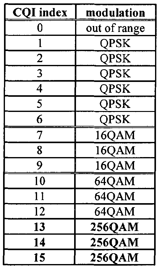


Claims
Priority Applications (5)
| Application Number | Priority Date | Filing Date | Title |
|---|---|---|---|
| US15/129,621 US9887824B2 (en) | 2014-03-28 | 2015-03-27 | Method and apparatus for reporting channel state information for supporting 256QAM in wireless access system |
| EP15769902.6A EP3125456B1 (en) | 2014-03-28 | 2015-03-27 | Method and apparatus for reporting channel state information for supporting 256qam in wireless access system |
| KR1020167024052A KR101842204B1 (en) | 2014-03-28 | 2015-03-27 | Method and apparatus for reporting channel state information for supporting 256qam in wireless access system |
| CN201580017085.7A CN106134120B (en) | 2014-03-28 | 2015-03-27 | Method and apparatus of the reporting channel status information to support 256QAM in wireless access system |
| JP2016559579A JP6392369B2 (en) | 2014-03-28 | 2015-03-27 | Channel state information reporting method and apparatus for supporting 256QAM in wireless access system |
Applications Claiming Priority (2)
| Application Number | Priority Date | Filing Date | Title |
|---|---|---|---|
| US201461971549P | 2014-03-28 | 2014-03-28 | |
| US61/971,549 | 2014-03-28 |
Publications (1)
| Publication Number | Publication Date |
|---|---|
| WO2015147592A1 true WO2015147592A1 (en) | 2015-10-01 |
Family
ID=54196003
Family Applications (1)
| Application Number | Title | Priority Date | Filing Date |
|---|---|---|---|
| PCT/KR2015/003044 WO2015147592A1 (en) | 2014-03-28 | 2015-03-27 | Method and apparatus for reporting channel state information for supporting 256qam in wireless access system |
Country Status (6)
| Country | Link |
|---|---|
| US (1) | US9887824B2 (en) |
| EP (1) | EP3125456B1 (en) |
| JP (1) | JP6392369B2 (en) |
| KR (1) | KR101842204B1 (en) |
| CN (1) | CN106134120B (en) |
| WO (1) | WO2015147592A1 (en) |
Cited By (4)
| Publication number | Priority date | Publication date | Assignee | Title |
|---|---|---|---|---|
| JP2018014719A (en) * | 2016-07-22 | 2018-01-25 | 華碩電腦股▲ふん▼有限公司 | Method and device for transmission or reception using beam forming in wireless communication system |
| CN109152078A (en) * | 2017-06-16 | 2019-01-04 | 电信科学技术研究院 | Sending method, method of reseptance, device, terminal and the base station of uplink control channel |
| US11234150B2 (en) | 2017-02-28 | 2022-01-25 | Guangdong Oppo Mobile Telecommunications Corp., Ltd. | Wireless communication method, terminal device, and network device |
| CN117580064A (en) * | 2023-08-11 | 2024-02-20 | 中国电信股份有限公司技术创新中心 | Method, device, network equipment, terminal and medium for selecting reporting sub-configuration |
Families Citing this family (18)
| Publication number | Priority date | Publication date | Assignee | Title |
|---|---|---|---|---|
| US9722848B2 (en) * | 2014-05-08 | 2017-08-01 | Intel Corporation | Techniques for using a modulation and coding scheme for downlink transmissions |
| CN104202115B (en) * | 2014-05-09 | 2019-05-07 | 中兴通讯股份有限公司 | The modulation processing method and device, base station, terminal of high-order coding |
| EP3902142A1 (en) * | 2016-05-12 | 2021-10-27 | MediaTek Inc. | Qc-ldpc coding methods and apparatus |
| CN114745037A (en) | 2017-01-09 | 2022-07-12 | Lg 电子株式会社 | Method and apparatus for reporting channel state information in wireless communication system |
| EP3579465B1 (en) * | 2017-02-05 | 2022-03-02 | LG Electronics Inc. | Method for determining modulation and coding scheme in wireless communication system, and device therefor |
| US10938537B2 (en) * | 2017-05-05 | 2021-03-02 | Qualcomm Incorporated | Techniques and apparatuses for channel state information feedback performance for introduction of 64-QAM in machine type communication devices |
| KR101963365B1 (en) * | 2017-07-21 | 2019-03-28 | 엘지전자 주식회사 | Method for transmitting and receiving channel state information reference signal in a wireless communication system and apparatus therefor |
| US11005549B2 (en) * | 2017-07-26 | 2021-05-11 | Qualcomm Incorporated | Dedicated channel state information reporting for a control channel |
| CN110999175A (en) * | 2017-08-08 | 2020-04-10 | 株式会社Ntt都科摩 | Wireless communication method |
| TWI693853B (en) * | 2017-09-19 | 2020-05-11 | 聯發科技股份有限公司 | Uplink transmission method and communication apparatus |
| DK3691155T3 (en) * | 2017-09-30 | 2022-04-11 | Guangdong Oppo Mobile Telecommunications Corp Ltd | METHOD OF CALCULATING CHANNEL QUALITY INDICATOR (CQI), TERMINAL UNIT AND NETWORK UNIT |
| KR20200085768A (en) * | 2017-11-16 | 2020-07-15 | 소니 주식회사 | Methods, infrastructure equipment and communication devices |
| US10505605B2 (en) | 2017-12-08 | 2019-12-10 | Huawei Technologies Co., Ltd. | Rank indication method, rank indication reporting method, device and system, and storage medium |
| CN108111195B (en) * | 2017-12-08 | 2023-02-14 | 华为技术有限公司 | Rank indication method, rank indication reporting method, device and system, and storage medium |
| CN111182626A (en) * | 2018-11-09 | 2020-05-19 | 北京展讯高科通信技术有限公司 | Information sending method, user terminal and computer readable storage medium |
| US11323231B2 (en) | 2019-02-12 | 2022-05-03 | Samsung Electronics Co., Ltd. | Adapting a number of repetitions for a physical uplink control channel |
| WO2021103004A1 (en) * | 2019-11-29 | 2021-06-03 | 华为技术有限公司 | Data transmission method and apparatus |
| US20210368489A1 (en) * | 2020-05-23 | 2021-11-25 | Qualcomm Incorporated | Cqi table selection in sidelink |
Citations (2)
| Publication number | Priority date | Publication date | Assignee | Title |
|---|---|---|---|---|
| US20130322376A1 (en) * | 2012-06-04 | 2013-12-05 | Interdigital Patent Holdings, Inc. | Communicating channel state information (csi) of multiple transmission points |
| US20140086174A1 (en) * | 2012-09-27 | 2014-03-27 | Samsung Electronics Co., Ltd | Method and apparatus for transmitting/receiving channel state information |
Family Cites Families (2)
| Publication number | Priority date | Publication date | Assignee | Title |
|---|---|---|---|---|
| JP5896619B2 (en) * | 2011-04-05 | 2016-03-30 | シャープ株式会社 | Terminal apparatus, base station apparatus, communication system, and communication method |
| US9648601B2 (en) * | 2012-08-24 | 2017-05-09 | Sun Patent Trust | Communication method, base station and user equipment using a set of legacy or aggressive CQI table and legacy or aggressive MCS table |
-
2015
- 2015-03-27 KR KR1020167024052A patent/KR101842204B1/en active IP Right Grant
- 2015-03-27 US US15/129,621 patent/US9887824B2/en active Active
- 2015-03-27 JP JP2016559579A patent/JP6392369B2/en active Active
- 2015-03-27 WO PCT/KR2015/003044 patent/WO2015147592A1/en active Application Filing
- 2015-03-27 EP EP15769902.6A patent/EP3125456B1/en active Active
- 2015-03-27 CN CN201580017085.7A patent/CN106134120B/en not_active Expired - Fee Related
Patent Citations (2)
| Publication number | Priority date | Publication date | Assignee | Title |
|---|---|---|---|---|
| US20130322376A1 (en) * | 2012-06-04 | 2013-12-05 | Interdigital Patent Holdings, Inc. | Communicating channel state information (csi) of multiple transmission points |
| US20140086174A1 (en) * | 2012-09-27 | 2014-03-27 | Samsung Electronics Co., Ltd | Method and apparatus for transmitting/receiving channel state information |
Non-Patent Citations (3)
| Title |
|---|
| HITACHI LTD.: "Discussion on Mechanism to Support 256QAM in TM 10", RL-141393, 3GPP TSG RAN WG1 #76BIS, Shenzhen, China, XP050787063, Retrieved from the Internet <URL:http://www.3gpp.org/ftp/tsg_ran/WG1_RL1/TSGR1_76b/Docs> [retrieved on 20140322] * |
| HUAWEI ET AL.: "Further discussions on CQI/MCS table design for 256QAM", RL-141120, 3GPP TSG RAN WG1 #76BIS, Shenzhen, China, XP050786795, Retrieved from the Internet <URL:http://www.3gpp.org/ftp/tsg_ran/WG1_RL1/TSGR1_76b/Docs> [retrieved on 20140322] * |
| LG ELECTRONICS: "Further details on 256QAM operation", RL-141338, 3GPP TSG RAN WG1 #76BIS, Shenzhen, China, XP050787010, Retrieved from the Internet <URL:http://www.3gpp.org/ftp/tsg_ran/WG1_RL1/TSGR1_76b/Docs> [retrieved on 20140322] * |
Cited By (8)
| Publication number | Priority date | Publication date | Assignee | Title |
|---|---|---|---|---|
| JP2018014719A (en) * | 2016-07-22 | 2018-01-25 | 華碩電腦股▲ふん▼有限公司 | Method and device for transmission or reception using beam forming in wireless communication system |
| US10887868B2 (en) | 2016-07-22 | 2021-01-05 | Asustek Computer Inc. | Method and apparatus for transmission or reception using beamforming in a wireless communication system |
| US11558856B2 (en) | 2016-07-22 | 2023-01-17 | Asustek Computer Inc. | Method and apparatus for transmission or reception using beamforming in a wireless communication system |
| US11234150B2 (en) | 2017-02-28 | 2022-01-25 | Guangdong Oppo Mobile Telecommunications Corp., Ltd. | Wireless communication method, terminal device, and network device |
| AU2017401773B2 (en) * | 2017-02-28 | 2022-05-12 | Guangdong Oppo Mobile Telecommunications Corp., Ltd. | Wireless communication method, terminal device, and network device |
| US11653247B2 (en) | 2017-02-28 | 2023-05-16 | Guangdong Oppo Mobile Telecommunications Corp., Ltd. | Wireless communication method, terminal device, and network device |
| CN109152078A (en) * | 2017-06-16 | 2019-01-04 | 电信科学技术研究院 | Sending method, method of reseptance, device, terminal and the base station of uplink control channel |
| CN117580064A (en) * | 2023-08-11 | 2024-02-20 | 中国电信股份有限公司技术创新中心 | Method, device, network equipment, terminal and medium for selecting reporting sub-configuration |
Also Published As
| Publication number | Publication date |
|---|---|
| KR20160138392A (en) | 2016-12-05 |
| EP3125456B1 (en) | 2019-06-19 |
| EP3125456A1 (en) | 2017-02-01 |
| US9887824B2 (en) | 2018-02-06 |
| JP6392369B2 (en) | 2018-09-19 |
| KR101842204B1 (en) | 2018-03-26 |
| CN106134120B (en) | 2019-07-16 |
| EP3125456A4 (en) | 2018-03-14 |
| US20170180099A1 (en) | 2017-06-22 |
| JP2017517914A (en) | 2017-06-29 |
| CN106134120A (en) | 2016-11-16 |
Similar Documents
| Publication | Publication Date | Title |
|---|---|---|
| US10116414B2 (en) | Method and apparatus for transmitting and receiving channel status information (CSI) for supporting 256QAM in wireless access system | |
| KR101842204B1 (en) | Method and apparatus for reporting channel state information for supporting 256qam in wireless access system | |
| JP6251398B2 (en) | Channel state information transmission / reception method and apparatus for supporting 256QAM in wireless connection system | |
| JP6298164B2 (en) | Method and apparatus for transmitting channel state information in wireless access system supporting machine communication | |
| KR102047707B1 (en) | Method and apparatus for transmitting channel state information in wireless access system supporting machine type communication | |
| US9794046B2 (en) | Method for transmitting uplink control information in wireless access system and apparatus therefor | |
| US9094966B2 (en) | Method for aperiodic feedback of channel state information in a wireless access system supporting multi-carrier aggregation | |
| US10757736B2 (en) | Method for supporting carrier sensing in wireless access system supporting unlicensed band, and device supporting same | |
| EP2704342A2 (en) | Method for transmitting channel state information in wireless access system and terminal therefor | |
| EP3076577B1 (en) | Methods and apparatuses for performing hybrid automatic retransmission request in wireless access system supporting machine-type communication | |
| WO2015084093A1 (en) | Method and apparatus for controlling uplink transmission power in wireless access system supporting machine-type communication | |
| WO2015084048A1 (en) | Methods and apparatuses for transmitting uplink in wireless access system supporting machine-type communication | |
| WO2014168410A1 (en) | Method and device for transmitting channel status information in wireless access system |
Legal Events
| Date | Code | Title | Description |
|---|---|---|---|
| 121 | Ep: the epo has been informed by wipo that ep was designated in this application |
Ref document number: 15769902 Country of ref document: EP Kind code of ref document: A1 |
|
| ENP | Entry into the national phase |
Ref document number: 20167024052 Country of ref document: KR Kind code of ref document: A |
|
| WWE | Wipo information: entry into national phase |
Ref document number: 15129621 Country of ref document: US |
|
| ENP | Entry into the national phase |
Ref document number: 2016559579 Country of ref document: JP Kind code of ref document: A |
|
| NENP | Non-entry into the national phase |
Ref country code: DE |
|
| REEP | Request for entry into the european phase |
Ref document number: 2015769902 Country of ref document: EP |
|
| WWE | Wipo information: entry into national phase |
Ref document number: 2015769902 Country of ref document: EP |