WO2015146883A1 - Polyester resin film, method for producing polyester resin film, polarizing plate, image display device, hard coat film, sensor film for touch panels, glass scattering prevention film and touch panel - Google Patents
Polyester resin film, method for producing polyester resin film, polarizing plate, image display device, hard coat film, sensor film for touch panels, glass scattering prevention film and touch panel Download PDFInfo
- Publication number
- WO2015146883A1 WO2015146883A1 PCT/JP2015/058674 JP2015058674W WO2015146883A1 WO 2015146883 A1 WO2015146883 A1 WO 2015146883A1 JP 2015058674 W JP2015058674 W JP 2015058674W WO 2015146883 A1 WO2015146883 A1 WO 2015146883A1
- Authority
- WO
- WIPO (PCT)
- Prior art keywords
- polyester resin
- resin film
- film
- formula
- stretching
- Prior art date
Links
Images
Classifications
-
- C—CHEMISTRY; METALLURGY
- C08—ORGANIC MACROMOLECULAR COMPOUNDS; THEIR PREPARATION OR CHEMICAL WORKING-UP; COMPOSITIONS BASED THEREON
- C08J—WORKING-UP; GENERAL PROCESSES OF COMPOUNDING; AFTER-TREATMENT NOT COVERED BY SUBCLASSES C08B, C08C, C08F, C08G or C08H
- C08J5/00—Manufacture of articles or shaped materials containing macromolecular substances
- C08J5/18—Manufacture of films or sheets
-
- B—PERFORMING OPERATIONS; TRANSPORTING
- B29—WORKING OF PLASTICS; WORKING OF SUBSTANCES IN A PLASTIC STATE IN GENERAL
- B29C—SHAPING OR JOINING OF PLASTICS; SHAPING OF MATERIAL IN A PLASTIC STATE, NOT OTHERWISE PROVIDED FOR; AFTER-TREATMENT OF THE SHAPED PRODUCTS, e.g. REPAIRING
- B29C55/00—Shaping by stretching, e.g. drawing through a die; Apparatus therefor
- B29C55/02—Shaping by stretching, e.g. drawing through a die; Apparatus therefor of plates or sheets
- B29C55/10—Shaping by stretching, e.g. drawing through a die; Apparatus therefor of plates or sheets multiaxial
- B29C55/12—Shaping by stretching, e.g. drawing through a die; Apparatus therefor of plates or sheets multiaxial biaxial
- B29C55/14—Shaping by stretching, e.g. drawing through a die; Apparatus therefor of plates or sheets multiaxial biaxial successively
- B29C55/143—Shaping by stretching, e.g. drawing through a die; Apparatus therefor of plates or sheets multiaxial biaxial successively firstly parallel to the direction of feed and then transversely thereto
-
- G—PHYSICS
- G02—OPTICS
- G02B—OPTICAL ELEMENTS, SYSTEMS OR APPARATUS
- G02B5/00—Optical elements other than lenses
- G02B5/30—Polarising elements
- G02B5/3025—Polarisers, i.e. arrangements capable of producing a definite output polarisation state from an unpolarised input state
-
- G—PHYSICS
- G02—OPTICS
- G02B—OPTICAL ELEMENTS, SYSTEMS OR APPARATUS
- G02B5/00—Optical elements other than lenses
- G02B5/30—Polarising elements
- G02B5/3083—Birefringent or phase retarding elements
-
- C—CHEMISTRY; METALLURGY
- C08—ORGANIC MACROMOLECULAR COMPOUNDS; THEIR PREPARATION OR CHEMICAL WORKING-UP; COMPOSITIONS BASED THEREON
- C08J—WORKING-UP; GENERAL PROCESSES OF COMPOUNDING; AFTER-TREATMENT NOT COVERED BY SUBCLASSES C08B, C08C, C08F, C08G or C08H
- C08J2367/00—Characterised by the use of polyesters obtained by reactions forming a carboxylic ester link in the main chain; Derivatives of such polymers
- C08J2367/02—Polyesters derived from dicarboxylic acids and dihydroxy compounds
-
- G—PHYSICS
- G02—OPTICS
- G02F—OPTICAL DEVICES OR ARRANGEMENTS FOR THE CONTROL OF LIGHT BY MODIFICATION OF THE OPTICAL PROPERTIES OF THE MEDIA OF THE ELEMENTS INVOLVED THEREIN; NON-LINEAR OPTICS; FREQUENCY-CHANGING OF LIGHT; OPTICAL LOGIC ELEMENTS; OPTICAL ANALOGUE/DIGITAL CONVERTERS
- G02F1/00—Devices or arrangements for the control of the intensity, colour, phase, polarisation or direction of light arriving from an independent light source, e.g. switching, gating or modulating; Non-linear optics
- G02F1/01—Devices or arrangements for the control of the intensity, colour, phase, polarisation or direction of light arriving from an independent light source, e.g. switching, gating or modulating; Non-linear optics for the control of the intensity, phase, polarisation or colour
- G02F1/13—Devices or arrangements for the control of the intensity, colour, phase, polarisation or direction of light arriving from an independent light source, e.g. switching, gating or modulating; Non-linear optics for the control of the intensity, phase, polarisation or colour based on liquid crystals, e.g. single liquid crystal display cells
- G02F1/133—Constructional arrangements; Operation of liquid crystal cells; Circuit arrangements
- G02F1/1333—Constructional arrangements; Manufacturing methods
- G02F1/133308—Support structures for LCD panels, e.g. frames or bezels
- G02F1/133311—Environmental protection, e.g. against dust or humidity
Definitions
- the present invention relates to a polyester resin film, a method for producing a polyester resin film, a polarizing plate, an image display device, a hard coat film, a sensor film for a touch panel, a glass scattering prevention film, and a touch panel.
- Image display devices such as liquid crystal display (LCD), plasma display (PDP), electroluminescence display (OELD or IELD), field emission display (FED), touch panel, and electronic paper have a polarizing plate on the display screen side of the image display panel. Is arranged. For example, a liquid crystal display device has low power consumption, and its application is expanding year by year as a space-saving image display device.
- a liquid crystal display device has a major disadvantage that the viewing angle dependence of a display image is large, but a wide viewing angle liquid crystal mode such as a VA (Virtual Alignment) mode and an IPS (In-Place-Switching) mode is put into practical use As a result, the demand for liquid crystal display devices is rapidly expanding even in markets where high-quality images such as televisions are required.
- VA Virtual Alignment
- IPS Intelligent Place-Switching
- a polarizing plate used in a liquid crystal display device is generally composed of a polarizer made of a polyvinyl alcohol film or the like on which iodine or dye is adsorbed and oriented, and a transparent protective film (polarizing plate protective film) on both sides of the polarizer. It has a configuration.
- the protective film on the surface (the side opposite to the display side) to be bonded to the liquid crystal cell is called an inner film, and the opposite side (display side) is called an outer film.
- Polyester resin films and the like have advantages such as low cost, high mechanical strength, and low moisture permeability, and therefore are expected to be used as outer films.
- polyester resin films are increasingly used as touch panel members such as transparent conductive films, scattering prevention films, and hard coat films. .
- a polyester resin film that can simultaneously improve rainbow unevenness when viewed from the front and rainbow unevenness when viewed from the oblique direction, a method for producing a polyester resin film, a polarizing plate, and an image.
- a display device, a hard coat film, a sensor film for a touch panel, a glass scattering prevention film, and a touch panel are provided.
- the present inventors have controlled the film thickness, the birefringence in the film in-plane direction, the birefringence in the film thickness direction, and the birefringence unevenness in the film plane. As a result, it was found that rainbow unevenness when the display is viewed from an oblique direction can be eliminated, and the present invention has been completed.
- the present invention which is a specific means for achieving the above object, is as follows.
- Th represents the thickness of the polyester resin film, the unit of the thickness of the polyester resin film is ⁇ m;
- nx represents the refractive index in the slow axis direction in the polyester resin film plane,
- ny represents the refractive index in the fast axis direction in the plane of the polyester resin film,
- nz represents the refractive index in the thickness direction of the polyester resin film, and
- n ⁇ represents (nx ⁇ ny) in an arbitrary area 1 m 2 of the polyester resin film.
- the polyester resin film according to [1] preferably satisfies the following formula (5); 130 ° C. ⁇ Tpre ⁇ 200 ° C.
- Formula (5) Tpre represents the pre-peak temperature measured by differential scanning calorimetry of the polyester resin film, and the unit is ° C.
- the polyester resin film according to [1] or [2] preferably has a polyester resin film density of 1.370 to 1.390 g / cm 3 .
- the polyester resin film according to any one of [1] to [3] has a thermal shrinkage ratio of 3.5 and TD in the polyester resin film after standing at 150 ° C. for 30 minutes. % Or less is preferable.
- the polyester resin film according to any one of [1] to [4] has a thermal shrinkage of 0.3% in the MD direction and the TD direction of the polyester resin film after standing at 80 ° C. for 24 hours. The following is preferable.
- the width of the polyester resin film is preferably 0.6 to 6 m.
- the polyester resin film according to any one of [1] to [6] is preferably biaxially oriented.
- a transverse stretching step of transversely stretching the polyester resin film after the longitudinal stretching in the width direction perpendicular to the longitudinal direction, A method for producing a polyester resin film satisfying the following formulas (1 ′) and (6) to (11); 15 ⁇ m ⁇ Th ′ ⁇ 60 ⁇ m Formula (1 ′) 2.8 ⁇ DMD ⁇ 3.6
- Th ′ represents the thickness of the polyester resin film after the transverse stretching step, and the unit of the thickness of the polyester resin film after the transverse stretching step is ⁇ m; Represents the draw ratio in the machine direction, DTD represents the draw ratio in the transverse direction, TSET represents the maximum surface temperature at the time of heat setting, TTDs represents the film surface temperature at the start of transverse stretching, and TTDe is the end of transverse stretching Represents the film surface temperature of the hour; units of TSET, TTDs, and TTDe are in ° C.
- nx (MD) represents the refractive index in the slow axis direction in the plane of the polyester resin film after longitudinal stretching
- ny (MD) represents the polyester resin film after longitudinal stretching
- the refractive index in the in-plane fast axis direction is represented, and nz (MD) represents the refractive index in the thickness direction of the polyester resin film after longitudinal stretching.
- the method for producing a polyester resin film according to [8] or [9] includes a heat fixing part for heating and crystallizing a heat-fixed portion of the polyester resin film after longitudinal stretching and transverse stretching, and heat fixing. Heating the formed polyester resin film, and including a step of transporting a thermal relaxation portion that relaxes the tension of the polyester resin film and removes residual distortion of the film, In the thermal relaxation portion, it is preferable that the longitudinal relaxation rate is 1 to 10% and the lateral relaxation rate is 3 to 23%.
- the method for producing a polyester resin film according to any one of [8] to [10] is a method of heating and crystallizing the heat-fixed polyester resin film after longitudinal and transverse stretching.
- the fixing unit includes a step of heating the heat-fixed polyester resin film, transporting a heat relaxation unit that relaxes the tension of the polyester resin film and removes residual distortion of the film, It is preferable that an intermediate cooling part is included between the laterally stretched part and the heat fixing part.
- the method for producing a polyester resin film according to [11] preferably satisfies the following formula (14) in the intermediate cooling section; 30 ° C. ⁇ TMC ⁇ (TTDe ⁇ 10) ° C.
- TMC represents the minimum film surface temperature
- TTDe represents the film surface temperature at the end of the transverse stretching
- both units are ° C.
- a polarizing plate comprising a polarizer and the polyester resin film according to any one of [1] to [7].
- An image display device comprising the polyester resin film according to any one of [1] to [7] or the polarizing plate according to claim 13.
- the image display device includes a light source unit having at least blue, green, and red light emission peaks, and a liquid crystal cell having polarizing plates on both sides, the green light emission peak of the light source unit, and red Of the emission peaks, the half width W having the smaller half width is preferably 50 nm or less.
- the light source unit includes at least a blue light emitting diode or an ultraviolet light emitting diode and a phosphor capable of emitting light by being excited by light from the blue light emitting diode or the ultraviolet light emitting diode. It is preferable.
- At least one of the phosphors is a quantum dot.
- a hard coat film comprising the polyester resin film according to any one of [1] to [7].
- a touch panel sensor film comprising the polyester resin film according to any one of [1] to [7].
- a glass scattering prevention film comprising the polyester resin film according to any one of [1] to [7].
- a touch panel provided with at least any one of a film and the glass scattering prevention film as described in [20].
- a polyester resin film capable of simultaneously improving rainbow unevenness when viewed from the front and rainbow unevenness when viewed from an oblique direction, a method for producing a polyester resin film, a polarizing plate, an image display device, and hardware
- a coat film, a sensor film for a touch panel, a glass scattering prevention film, and a touch panel can be provided.
- a numerical range expressed using “to” means a range including numerical values described before and after “to” as a lower limit value and an upper limit value.
- the polyester resin film of the present invention (hereinafter also simply referred to as “film”) satisfies the following formulas (1) to (4). 15 ⁇ m ⁇ Th ⁇ 60 ⁇ m (1) 0 ⁇ nx ⁇ ny ⁇ 0.020 (2) 0.120 ⁇ (nx + ny) / 2 ⁇ nz ⁇ 0.160 Formula (3) 0 ⁇ n ⁇ ⁇ 0.014 (4)
- Th represents the thickness of the polyester resin film, the unit of the thickness of the polyester resin film is ⁇ m;
- nx represents the refractive index in the slow axis direction in the polyester resin film plane,
- ny represents the refractive index in the fast axis direction in the plane of the polyester resin film,
- nz represents the refractive index in the thickness direction of the polyester resin film, and
- n ⁇ represents (nx ⁇ ny) in an arbitrary area 1 m 2 of the polyester resin film. It represents the difference between the maximum and minimum values.
- the polyester resin film of the present invention can simultaneously improve rainbow unevenness when viewed from the front and rainbow unevenness when viewed from an oblique direction.
- the rainbow unevenness when viewed from the front can be improved by reducing the in-plane birefringence, but the rainbow unevenness when viewed from an oblique direction cannot be improved.
- the maximum thickness and the minimum of the birefringence in the film plane, the birefringence in the thickness direction of the film, and the birefringence in the plane within an arbitrary area 1 m 2 of the film are set in a specific range.
- the thickness of the polyester resin film of the present invention satisfies the following formula (1), preferably satisfies the following formula (1-2), and more preferably satisfies the following formula (1-3).
- 15 ⁇ m ⁇ Th ⁇ 60 ⁇ m (1) 20 ⁇ m ⁇ Th ⁇ 55 ⁇ m Formula (1-2) 23 ⁇ m ⁇ Th ⁇ 50 ⁇ m Formula (1-3)
- Th represents the thickness ( ⁇ m) of the polyester resin film.
- the thickness of the polyester resin film is 60 ⁇ m or less, rainbow unevenness becomes difficult to see.
- the thickness Th of the polyester resin film for example, using a contact-type film thickness meter, 50 points are sampled at equal intervals over 0.5 m in the longitudinally stretched direction (longitudinal direction), and further, the film width direction (perpendicular to the longitudinal direction). ) was sampled at regular intervals (50 equal parts in the width direction) over the entire width of the film, and the thicknesses of these 100 points were measured. The average thickness of these 100 points was determined and used as the thickness of the polyester film.
- the in-plane birefringence of the polyester resin film of the present invention satisfies the following formula (2), preferably satisfies the following formula (2-2), and more preferably satisfies the following formula (2-3).
- nx represents the refractive index in the slow axis direction in the polyester resin film surface
- ny represents the refractive index in the fast axis direction in the polyester resin film surface.
- the in-plane birefringence of the polyester resin film of the present invention is larger than 0, the in-plane birefringence distribution (n ⁇ ) does not become too large, and rainbow unevenness becomes difficult to see. If the in-plane birefringence of the polyester resin film of the present invention is 0.020 or less, rainbow unevenness is difficult to see.
- the birefringence in the thickness direction of the polyester resin film of the present invention satisfies the following formula (3) from the viewpoint of rainbow unevenness, preferably satisfies the following formula (3-2), and satisfies the following formula (3-3): It is more preferable.
- nx represents the refractive index in the slow axis direction in the polyester resin film surface
- ny represents the refractive index in the fast axis direction in the polyester resin film surface
- nz represents the refractive index in the polyester resin film thickness direction. If the birefringence in the thickness direction of the polyester resin film of the present invention is less than 0.120, the vertical and horizontal orientations become too small, causing problems in film strength, and the film cannot be formed. If the birefringence in the thickness direction of the polyester resin film of the present invention is less than 0.160, rainbow unevenness is difficult to see.
- nx, ny, and nz can be measured as follows. Using two polarizing plates, the orientation axis direction of the polyester resin film was determined, and a 4 cm ⁇ 2 cm rectangle was cut out so that the orientation axis directions were perpendicular to each other, and used as a measurement sample. For this sample, the biaxial refractive index (nx, ny) perpendicular to each other and the refractive index (nz) in the thickness direction were determined by an Abbe refractometer, and equations (2) to (4) were determined.
- the unevenness (in-plane birefringence distribution) as a difference between the maximum value and the minimum value of (nx ⁇ ny) in an arbitrary area 1 m 2 of the polyester resin film of the present invention satisfies the following formula (4), and It is preferable to satisfy the formula (4-2), and it is more preferable to satisfy the following formula (4-3).
- n ⁇ For a polyester resin film 1 m 2, uniformly sampled film width direction, the flow direction for each 100 mm. For example, in the case of a film having a film width of 2 m and a film length of 0.5 m, a total of 100 film pieces are cut out, 20 points in the width direction and 5 points in the flow direction. About the magnitude
- In-plane birefringence, birefringence in the thickness direction, and in-plane birefringence distribution are the types of polyester resin used in the film, the amount of the polyester resin and additives, the addition of a retardation developer, and the film thickness.
- the film can be adjusted by the stretching direction and stretching ratio of the film.
- the pre-peak temperature measured by differential scanning calorimetry preferably satisfies the following formula (5), more preferably satisfies the following formula (5-2), and the following formula ( It is more preferable to satisfy 5-3).
- the pre-peak temperature measured by differential scanning calorimetry preferably satisfies the following formula (5), more preferably satisfies the following formula (5-2), and the following formula ( It is more preferable to satisfy 5-3).
- Formula (5) 140 ° C. ⁇ Tpre ⁇ 190 ° C.
- Formula (5-2) 150 ° C. ⁇ Tpre ⁇ 180 ° C.
- Tpre represents a pre-peak temperature measured by differential scanning calorimetry of a polyester resin film, and its unit is ° C.
- the pre-peak temperature By setting the pre-peak temperature to 130 ° C. or higher, rainbow unevenness can be suppressed, and further, the problem of strength and heat resistance of the polyester resin film can be solved due to insufficient crystallization.
- the polyester resin film can be controlled so that the in-plane birefringence distribution falls within the ranges of the above formulas (3) and (4), and the rainbow unevenness becomes difficult to see.
- DSC is an abbreviation for differential scanning calorimetry
- the “pre-peak temperature” of DSC is the temperature of the peak that appears first when the polyester resin film is subjected to DSC measurement.
- the DSC pre-peak temperature generally corresponds to the highest film surface temperature (heat setting temperature) of the polyester resin film at the time of heat setting during the transverse stretching step performed by uniaxial stretching of the polyester resin film.
- the DSC pre-peak temperature is a value obtained by a conventional method in differential scanning calorimetry (DSC).
- the density of the polyester resin film of the present invention is preferably 1.370 to 1.390 g / cm 3 , more preferably 1.372 to 1.388 g / cm 3 , and 1.374 to 1.386 g. More preferably, it is / m 3 .
- a density 1.370g / cm 3 or more it is possible to eliminate the film strength and heat resistance issues, With 1.390g / cm 3 or less, rainbow unevenness is hardly visible.
- the density can be measured according to JIS K7112.
- the thermal shrinkage in the MD direction and TD direction of the polyester resin film after standing at 150 ° C. for 30 minutes is preferably 3.5% or less, more preferably 3% or less. More preferably, it is 5% or less.
- the thermal shrinkage rate is set to 3.5% or less, the shrinkage of the polyester resin film is suppressed when used in a liquid crystal display device or a touch panel, and display failure is less likely to occur.
- the heat shrinkage rate in the MD direction of the film after standing at 150 ° C. for 30 minutes is defined as follows. Two reference lines are put in advance in a sample piece M of a polyester resin film cut in 30 mm in the TD direction and 120 mm in the MD direction so as to have an interval of 100 mm in the MD direction in advance. After leaving the sample piece M in a heating oven at 150 ° C. for 30 minutes under no tension, the sample piece M is cooled to room temperature, and the interval between the two reference lines is measured. The interval after processing measured at this time is A [mm]. The numerical value [%] calculated by using the formula “100 ⁇ (100 ⁇ A) / 100” from the interval 100 mm before the processing and the interval Amm after the processing is used as the MD thermal contraction rate (S ).
- the thermal shrinkage rate in the TD direction of the film after standing at 150 ° C. for 30 minutes is defined as follows. Two reference lines are put in advance in a sample piece M of a polyester resin film cut in 30 mm in the MD direction and 120 mm in the TD direction so as to have an interval of 100 mm in the TD direction. After leaving the sample piece M in a heating oven at 150 ° C. for 30 minutes under no tension, the sample piece M is cooled to room temperature, and the interval between the two reference lines is measured. The interval after processing measured at this time is A [mm]. The numerical value [%] calculated by using the formula “100 ⁇ (100 ⁇ A) / 100” from the interval 100 mm before the processing and the interval Amm after the processing is used as the TD thermal contraction rate (S ).
- the film conveyance direction is also referred to as MD (Machine Direction) direction.
- the MD direction of the film is also referred to as the longitudinal direction of the film.
- the film width direction is a direction orthogonal to the longitudinal direction.
- the film width direction is also called a TD (Transverse Direction) direction in a film manufactured while transporting the film.
- the film width direction is referred to as TD or TD direction
- the direction orthogonal to the film width direction is referred to as MD or MD direction.
- the heat shrinkage in the MD direction is also referred to as MD heat shrinkage, and the ratio is referred to as MD heat shrinkage rate. Therefore, the thermal contraction rate in the direction orthogonal to the film width direction is also expressed as MD thermal contraction rate.
- the thermal shrinkage in the MD direction and TD direction of the polyester resin film after standing at 80 ° C. for 24 hours is preferably 0.3% or less, more preferably 0.2% or less, More preferably, it is 0.15% or less.
- the thermal shrinkage rate is set to 0.3% or less, the shrinkage of the polyester resin film is suppressed when used for a liquid crystal display device or a touch panel, and display failure is less likely to occur.
- the thermal shrinkage rate in the MD direction of the film after standing at 80 ° C. for 24 hours is defined as follows. Two reference lines are put in advance in a sample piece M of a polyester resin film cut in 30 mm in the TD direction and 120 mm in the MD direction so as to have an interval of 100 mm in the MD direction in advance. After leaving the sample piece M in a heating oven at 80 ° C. under no tension for 24 hours, the sample piece M is cooled to room temperature, and the interval between the two reference lines is measured. The interval after processing measured at this time is A [mm]. The numerical value [%] calculated by using the formula “100 ⁇ (100 ⁇ A) / 100” from the interval 100 mm before the processing and the interval Amm after the processing is used as the MD thermal contraction rate (S ).
- the thermal shrinkage rate in the TD direction of the film after standing at 80 ° C. for 24 hours is defined as follows. Two reference lines are put in advance in a sample piece M of a polyester resin film cut in 30 mm in the MD direction and 120 mm in the TD direction so as to have an interval of 100 mm in the TD direction. After leaving the sample piece M in a heating oven at 80 ° C. under no tension for 24 hours, the sample piece M is cooled to room temperature, and the interval between the two reference lines is measured. The interval after processing measured at this time is A [mm]. The numerical value [%] calculated by using the formula “100 ⁇ (100 ⁇ A) / 100” from the interval 100 mm before the processing and the interval Amm after the processing is used as the TD thermal contraction rate (S ).
- the width of the polyester resin film of the present invention is preferably 0.6 to 6 m, more preferably 0.8 to 5.6 m, and further preferably 1.0 to 3.0 m.
- the polyester resin film of the present invention has a non-uniformity (hereinafter also referred to as width-direction orientation angle unevenness) of 15 ° or less as a difference between the maximum value and the minimum value of the orientation angle in the film width direction. It is preferable from the viewpoint that the shrinkage rate unevenness does not become excessively large and the film is difficult to break in the subsequent process.
- the orientation angle unevenness in the width direction is more preferably 12 ° or less, further preferably 10 ° or less, and most preferably 8 ° or less.
- the polyester resin film of the present invention is preferably biaxially oriented. Specifically, the polyester resin film of the present invention preferably has a refractive index in the longitudinal direction of 1.590 or less and a crystallinity exceeding 5%. The degree of crystallinity of the polyester resin film of the present invention is preferably 5% or more, more preferably 20% or more, and further preferably 30% or more.
- the polyester resin film of the present invention contains a polyester resin.
- the polyester resin film of the present invention may be a single layer film having a polyester resin as a main component, or may be a multilayer film having at least one layer having a polyester resin as a main component.
- the surface treatment may be performed on both surfaces or one surface of these single layer films or multilayer films, and this surface treatment is performed by corona treatment, saponification treatment, heat treatment, ultraviolet irradiation, electron beam irradiation, or the like. Modification may be sufficient, and thin film formation by application
- the mass ratio of the polyester resin in the entire film is usually 50% by mass or more, preferably 70% by mass or more, more preferably 90% by mass or more.
- polyester resin one having a composition of [0042] of WO2012 / 157762 is preferably used.
- polyester polyethylene terephthalate (PET), polyethylene naphthalate (PEN), polybutylene terephthalate (PBT), polycyclohexanedimethylene terephthalate (PCT), etc.
- PET and PEN are more preferable because of cost and heat resistance. More preferably, it is PET (PEN has a slight Re / Rth, that is, in-plane retardation / thickness direction retardation tends to be small).
- Polyester is most preferably polyethylene terephthalate, but polyethylene naphthalate can also be preferably used. For example, those described in JP-A-2008-39803 can be preferably used.
- Polyethylene terephthalate is a polyester having a structural unit derived from terephthalic acid as a dicarboxylic acid component and a structural unit derived from ethylene glycol as a diol component, and 80 mol% or more of all repeating units are preferably ethylene terephthalate.
- the structural unit derived from other copolymerization components may be included.
- copolymer components include isophthalic acid, p- ⁇ -oxyethoxybenzoic acid, 4,4′-dicarboxydiphenyl, 4,4′-dicarboxybenzophenone, bis (4-carboxyphenyl) ethane, adipic acid , Dicarboxylic acid components such as sebacic acid, 5-sodium sulfoisophthalic acid, 1,4-dicarboxycyclohexane, propylene glycol, butanediol, neopentyl glycol, diethylene glycol, cyclohexanediol, bisphenol A ethylene oxide adduct, polyethylene glycol And diol components such as polypropylene glycol and polytetramethylene glycol.
- Dicarboxylic acid components such as sebacic acid, 5-sodium sulfoisophthalic acid, 1,4-dicarboxycyclohexane, propylene glycol, butanediol
- dicarboxylic acid components and diol components can be used in combination of two or more if necessary.
- an oxycarboxylic acid such as p-oxybenzoic acid can be used in combination with the carboxylic acid component or diol component.
- a dicarboxylic acid component and / or a diol component containing a small amount of an amide bond, a urethane bond, an ether bond, a carbonate bond, or the like may be used.
- Polyethylene terephthalate can be produced by a direct polymerization method in which terephthalic acid and ethylene glycol and, if necessary, other dicarboxylic acid and / or other diol are directly reacted, dimethyl ester of terephthalic acid and ethylene glycol, and necessary
- any production method such as a so-called transesterification method in which a dimethyl ester of another dicarboxylic acid and / or another diol is transesterified can be applied.
- the intrinsic viscosity IV of the polyester resin is preferably 0.5 or more and 0.9 or less, more preferably 0.52 or more and 0.8 or less, and still more preferably Is 0.54 or more and 0.7 or less.
- solid phase polymerization may be used in combination with the melt polymerization described later when the polyester resin is synthesized.
- the acetaldehyde content of the polyester resin is preferably 50 ppm or less. More preferably, it is 40 ppm or less, Most preferably, it is 30 ppm or less. Acetaldehyde easily causes a condensation reaction between acetaldehydes, and water is generated as a side reaction product, which may cause hydrolysis of the polyester. The lower limit of the acetaldehyde content is practically about 1 ppm.
- (1-3) Catalyst For the polymerization of the polyester resin, Sb, Ge, Ti, Al-based catalysts are used, preferably Sb, Ti, Al-based catalysts, and more preferably Al-based catalysts. That is, it is preferable that the polyester resin used as the raw material resin is polymerized using an aluminum catalyst.
- an Al-based catalyst Re (in-plane retardation) is more easily expressed than when other catalysts (for example, Sb, Ti) are used, and PET can be thinned. That is, it means that the Al-based catalyst is more easily oriented. This is presumed to be due to the following reasons.
- the Al-based catalyst has a lower reactivity (polymerization activity) than Sb and Ti, the reaction is mild, and a by-product (diethylene glycol unit: DEG) is hardly generated. As a result, the regularity of PET increases, and it is easy to be oriented and to develop in-plane birefringence.
- Al-based catalyst As the Al-based catalyst, those described in [0013] to [0148] of WO2011 / 040161 ([0021] to [0123] of US2012 / 0183761) are used. The contents described in these publications are incorporated herein by reference.
- the method for polymerizing the polyester resin using the Al-based catalyst is not particularly limited, but specifically, [0091] to [0094] of WO2012 / 008488 ([0144] to US2013 / 0112271) [0153]) can be used to polymerize according to these publications, the contents of which are incorporated herein.
- Such Al-based catalysts include, for example, [0052] to [0054], [0099] to [0104] of JP2012-122051 ([0045] to [0047], [0091] of WO2012 / 029725. To [0096]) can be prepared according to these publications, and the contents described in these publications are incorporated herein.
- the amount of the Al-based catalyst is preferably 3 to 80 ppm, more preferably 5 to 60 ppm, and still more preferably 5 to 40 ppm as the amount of Al element with respect to the mass of the polyester resin.
- Sb-based catalyst As the Sb-based catalyst, those described in JP-A-2012-41519, [0050], [0052] to [0054] can be used.
- the method for polymerizing the polyester resin using the Sb-based catalyst is not particularly limited. Specifically, the polymerization can be performed according to [0086] to [0087] of WO2012 / 157762.
- additive It is also preferable to add a known additive to the polyester resin film of the present invention.
- a known additive include ultraviolet absorbers, particles, lubricants, antiblocking agents, heat stabilizers, antioxidants, antistatic agents, light resistance agents, impact resistance improvers, lubricants, dyes, pigments and the like.
- the polyester resin film generally requires transparency, it is preferable to keep the additive amount to a minimum.
- the polyester resin film of the present invention may contain an ultraviolet absorber in order to prevent the liquid crystal or the like of the liquid crystal display from being deteriorated by ultraviolet rays.
- the ultraviolet absorber is not particularly limited as long as it is a compound having ultraviolet absorbing ability and can withstand the heat applied in the production process of the polyester resin film.
- As the ultraviolet absorber there are an organic ultraviolet absorber and an inorganic ultraviolet absorber. From the viewpoint of transparency, an organic ultraviolet absorber is preferable. Those described in [0057] of WO2012 / 157762 and cyclic iminoester-based ultraviolet absorbers described later can be used.
- the cyclic imino ester-based ultraviolet absorber is not limited to the following, and examples thereof include 2-methyl-3,1-benzoxazin-4-one and 2-butyl-3,1-benzoxazine-4. -One, 2-phenyl-3,1-benzoxazin-4-one, 2- (1- or 2-naphthyl) -3,1-benzoxazin-4-one, 2- (4-biphenyl) -3, 1-benzoxazin-4-one, 2-p-nitrophenyl-3,1-benzoxazin-4-one, 2-m-nitrophenyl-3,1-benzoxazin-4-one, 2-p-benzoyl Phenyl-3,1-benzoxazin-4-one, 2-p-methoxyphenyl-3,1-benzoxazin-4-one, 2-o-methoxyphenyl-3,1-benzoxazin-4-one 2-cyclohexyl-3,1-benzoxazin-4-one, 2-
- a benzoxazinone-based compound which is difficult to be yellowed is preferably used.
- a compound represented by the following general formula (1) is more preferably used. It is done.
- R represents a divalent aromatic hydrocarbon group
- X 1 and X 2 are each independently selected from hydrogen or the following functional group group, but are not necessarily limited thereto. Absent.
- 2,2 ′-(1,4-phenylene) bis (4H-3,1-benzoxazin-4-one) is particularly preferable in the present invention.
- the amount of the ultraviolet absorber to be contained in the polyester resin film of the present invention is usually 10.0% by mass or less, preferably 0.3 to 3.0% by mass.
- the ultraviolet absorber may bleed out on the surface, which may cause deterioration of surface functionality such as adhesion deterioration.
- the ultraviolet absorber is preferably blended in the intermediate layer.
- this compound can be prevented from bleeding out to the film surface, and as a result, characteristics such as film adhesion can be maintained.
- the masterbatch method described in [0050] to [0051] of WO2011 / 162198 can be used for these formulations.
- the method for producing a polyester resin film of the present invention includes a step of melt-extruding a polyester raw material resin into a sheet shape, cooling on a casting drum to form a polyester resin film, and longitudinally stretching the formed polyester resin film in the longitudinal direction.
- 15 ⁇ m ⁇ Th ′ ⁇ 60 ⁇ m Formula (1 ′) 2.8 ⁇ DMD ⁇ 3.6 Formula (6)
- Formula (8) 80 ° C. ⁇ TTDs ⁇ 120 ° C.
- Formula (9) 120 ° C. ⁇ TTDe ⁇ 180 ° C.
- Formula (10) 20 ° C. ⁇ TTDe ⁇ TTDs ⁇ 80 ° C.
- Th ′ represents the thickness of the polyester resin film after the transverse stretching step, and the unit of the thickness of the polyester resin film after the transverse stretching step is ⁇ m;
- DTD represents the draw ratio in the transverse direction
- TSET represents the maximum surface temperature at the time of heat setting
- TTDs represents the film surface temperature at the start of transverse stretching
- TTDe is the end of transverse stretching Represents the film surface temperature of the hour; units of TSET, TTDs, and TTDe are in ° C.
- the method for producing a polyester resin film of the present invention includes a preheating portion for preheating the polyester resin film after longitudinal stretching to a temperature at which the polyester resin film can be stretched, and stretching the preheated polyester resin film in the width direction perpendicular to the longitudinal direction.
- the heat-fixed part that heats and crystallizes the stretched part, the longitudinally stretched and the laterally stretched polyester resin film, and heat-sets, heats the polyester resin film that is heat-fixed, and relaxes the tension of the polyester resin film It is preferable to convey the polyester resin film in this order to a heat relaxation part for removing residual distortion of the film and a cooling part for cooling the polyester resin film after heat relaxation.
- the draw ratio in the machine direction and the transverse direction are within a specific range, and the highest reached film surface temperature at the time of heat setting, the film surface temperature at the start of transverse stretching, and the end of transverse stretching.
- polyester resin film of this invention can be manufactured by a well-known method.
- the preferable aspect of the manufacturing method of the polyester resin film of this invention is demonstrated.
- the unstretched polyester resin film is preferably formed into a film by melt-extruding the polyester resin. It is preferable to dry the polyester resin or the master batch of the polyester resin and additive produced by the above-described master batch method to a moisture content of 200 ppm or less, and then introduce the melt into a single or twin screw extruder and melt it. At this time, in order to suppress degradation of the polyester, it is also preferable to melt in nitrogen or vacuum.
- the detailed conditions can be implemented in accordance with these publications with the aid of Patent Nos. 4992661 [0051] to [0052] (US 2013/0100378 publication [0085] to [0086]) and are described in these publications. The contents are incorporated herein. Furthermore, it is also preferable to use a gear pump in order to increase the delivery accuracy of the molten resin (melt). It is also preferable to use a 3 ⁇ m to 20 ⁇ m filter for removing foreign substances.
- melt containing the polyester resin melt-kneaded from the die it may be extruded as a single layer or as a multilayer.
- a layer containing an ultraviolet grade agent (UV agent) and a layer not containing it may be laminated.
- UV agent ultraviolet grade agent
- the bleed-out UV agent is undesirably easily transferred to a pass roll in the film-forming process, increasing the coefficient of friction between the film and the roll, and causing scratches.
- the thickness of the inner layer (ratio to the total layer) of the obtained polyester resin film is preferably 50% to 95%, more preferably 60% to 90%. More preferably, it is 70% or more and 85% or less.
- Such lamination can be performed by using a feed block die or a multi-manifold die.
- the refractive index in the longitudinal direction of the unstretched polyester resin film is preferably 1.590 or less, more preferably 1.585 or less, and further preferably 1.580 or less.
- the crystallinity of the unstretched polyester resin film is preferably 5% or less, more preferably 3% or less, and even more preferably 1% or less.
- the crystallinity degree of the unstretched polyester resin film here means the crystallinity degree of the center part of a film width direction.
- a polymer layer (preferably an easy-adhesion layer) may be formed by coating before or after stretching described later.
- the polymer layer generally include a functional layer that the polarizing plate may have, and among them, it is preferable to form an easy adhesion layer as the polymer layer.
- the easy-adhesion layer can be applied by the method described in [0062] to [0070] of WO2012 / 157762.
- the production method of the present invention includes a longitudinal stretching step of longitudinally stretching the molded polyester resin film in the longitudinal direction.
- the longitudinal stretching of the film is performed, for example, by applying tension between two or more pairs of nip rolls arranged in the film conveyance direction while passing the film through a pair of nip rolls sandwiching the film and conveying the film in the longitudinal direction of the film. be able to.
- the rotational speed of the nip roll B on the downstream side is By making it faster than the rotational speed of the nip roll A on the upstream side, the film is stretched in the transport direction (MD direction).
- Two or more pairs of nip rolls may be installed independently on the upstream side and the downstream side, respectively.
- the stretching ratio in the longitudinal direction of the polyester resin film satisfies the following formula (6), preferably satisfies the following formula (6-2), and more preferably satisfies the following formula (6-3). . 2.8 ⁇ DMD ⁇ 3.6 Formula (6) 2.9 ⁇ DMD ⁇ 3.5 Formula (6-2) 3.0 ⁇ DMD ⁇ 3.4 Formula (6-3)
- DMD represents the stretching ratio in the longitudinal direction.
- the area stretch ratio represented by the product of the longitudinal and lateral stretch ratios is preferably 6 to 18 times, more preferably 8 to 16 times, more preferably 9 to 15 times the area of the polyester resin film before stretching. More preferably, it is double.
- the temperature during the longitudinal stretching of the polyester resin film (hereinafter also referred to as “longitudinal stretching temperature”) is preferably Tg ⁇ 20 ° C. or more and Tg + 50 ° C. or less when the glass transition temperature of the polyester resin film is Tg. It is preferably Tg-10 ° C. or higher and Tg + 40 ° C. or lower, more preferably Tg ° C. or higher and Tg + 30 ° C. or lower.
- the polyester resin film in contact with the roll is heated by providing a pipe that can flow a heater or a hot solvent inside the roll. can do.
- a polyester resin film can be heated by spraying a warm air on a polyester resin film, making it contact with heat sources, such as a heater, or letting the vicinity of a heat source pass.
- the polyester resin film is at least 2 in the longitudinal direction (conveying direction, MD) of the polyester resin film and the direction (TD direction) orthogonal to the longitudinal direction of the polyester resin film. It will stretch to the axis. The stretching in the MD direction and the TD direction may be performed at least once each.
- the direction (TD) orthogonal to the longitudinal direction (conveyance direction, MD) of a polyester resin film intends the direction perpendicular
- a direction in which the angle with respect to the longitudinal direction (that is, the conveyance direction) can be regarded as 90 ° due to mechanical errors or the like (for example, a direction of 90 ° ⁇ 5 ° with respect to the MD direction) is included.
- the biaxial stretching method may be any of a sequential biaxial stretching method in which longitudinal stretching and lateral stretching are separated and a simultaneous biaxial stretching method in which longitudinal stretching and lateral stretching are simultaneously performed.
- the longitudinal stretching and the lateral stretching may be independently performed twice or more, and the order of the longitudinal stretching and the lateral stretching is not limited.
- stretching modes such as longitudinal stretching ⁇ transverse stretching, longitudinal stretching ⁇ transverse stretching ⁇ longitudinal stretching, longitudinal stretching ⁇ longitudinal stretching ⁇ transverse stretching, transverse stretching ⁇ longitudinal stretching can be mentioned. Of these, longitudinal stretching ⁇ transverse stretching is preferred.
- the birefringence of the film after longitudinal stretching and before lateral stretching preferably satisfies the following formula (12), more preferably satisfies the following formula (12-2), and satisfies the following formula (12-3). Further preferred.
- nx (MD) represents the refractive index in the slow axis direction in the plane of the polyester resin film after longitudinal stretching
- ny (MD) represents the fast axis direction in the plane of the polyester resin film after longitudinal stretching.
- Expression (12) exceeds 0.030 and is equal to or less than 0.090, control within the predetermined range in Expressions (2) to (4) can be performed, and rainbow unevenness becomes difficult to see.
- the birefringence of the film after longitudinal stretching and before lateral stretching preferably satisfies the following formula (13) in addition to satisfying the above formula (12), and preferably satisfies the following formula (13-2): It is more preferable that the following formula (13-3) is satisfied.
- nx (MD) represents the refractive index in the slow axis direction in the plane of the polyester resin film after longitudinal stretching
- ny (MD) represents the fast axis direction in the plane of the polyester resin film after longitudinal stretching
- nz (MD) represents the refractive index in the thickness direction of the polyester resin film after longitudinal stretching. If the expression (13) is 0.030 or more and less than 0.090, it becomes possible to control within the predetermined range in the above expressions (2) to (4), and the rainbow unevenness becomes difficult to see.
- nx (MD), ny (MD), and nz (MD) can be measured by the same method as the above nx, ny, and nz.
- the polyester resin film after longitudinal stretching is stretched in the width direction perpendicular to the longitudinal direction.
- the transverse stretching step in the present invention is a step of transversely stretching the polyester resin film after longitudinal stretching in the width direction orthogonal to the longitudinal direction.
- A a preheating portion for preheating the polyester resin film after longitudinal stretching to a temperature at which it can be stretched;
- B a stretched part that stretches the preheated polyester resin film in a transverse direction by applying tension to the width direction perpendicular to the longitudinal direction;
- C a heat fixing part for heating and crystallizing the heat-fixed polyester resin film after the longitudinal stretching and the transverse stretching;
- D a heat relaxation portion that heats the heat-fixed polyester resin film, relaxes the tension of the polyester resin film, and removes residual strain of the film; and
- E It is preferable to convey a polyester resin film in this order to the cooling part which cools the polyester resin film after heat relaxation.
- the specific means is not limited as long as the polyester resin film is transversely stretched in the above configuration, but a lateral stretching apparatus or biaxial capable of processing each step constituting the above configuration. It is preferable to use a stretching machine.
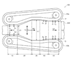
- the biaxial stretching machine 100 includes a pair of annular rails 60a and 60b, and gripping members 2a to 2l attached to the respective annular rails and movable along the rails.
- the annular rails 60a and 60b are arranged symmetrically with respect to the polyester resin film 200, and can be stretched in the film width direction by holding the polyester resin film 200 with the gripping members 2a to 2l and moving along the rails. It is like that.
- FIG. 1 is a top view showing an example of a biaxial stretching machine from the top.
- the biaxial stretching machine 100 includes a preheating unit 10 that preheats the polyester resin film 200 and a stretching unit that stretches the polyester resin film 200 in the arrow TD direction, which is a direction orthogonal to the arrow MD direction, and applies tension to the polyester resin film. 20, a heat fixing portion 30 for heating the tensioned polyester resin film while applying tension, and a heat relaxation portion 40 for relaxing the tension of the heat-fixed polyester resin film by heating.
- the cooling part 50 which cools the polyester resin film which passed through the heat relaxation part is comprised.
- Grip members 2a, 2b, 2e, 2f, 2i, and 2j that are movable along the annular rail 60a are attached to the annular rail 60a, and the annular rail 60b is movable along the annular rail 60b.
- Gripping members 2c, 2d, 2g, 2h, 2k, and 2l are attached.
- the grip members 2a, 2b, 2e, 2f, 2i, and 2j grip one end of the polyester resin film 200 in the TD direction, and the grip members 2c, 2d, 2g, 2h, 2k, and 2l are polyester resins. The other end of the film 200 in the TD direction is gripped.
- the gripping members 2a to 2l are generally called chucks, clips, and the like.
- the gripping members 2a, 2b, 2e, 2f, 2i, and 2j move counterclockwise along the annular rail 60a, and the gripping members 2c, 2d, 2g, 2h, 2k, and 2l move along the annular rail 60b. Move clockwise.
- the gripping members 2a to 2d grip the end portion of the polyester resin film 200 in the preheating portion 10 and move along the annular rail 60a or 60b while being gripped, and the extending portion 20 and the gripping members 2e to 2h are located. It proceeds through the thermal relaxation section 40 to the cooling section 50 where the gripping members 2i to 2l are located. Thereafter, the gripping members 2a and 2b and the gripping members 2c and 2d are separated from the end of the polyester resin film 200 at the end of the cooling unit 50 on the downstream side in the MD direction in the transport direction, and then the annular rail 60a or It moves along 60b and returns to the preheating part 10.
- the polyester resin film 200 moves in the direction of the arrow MD, and sequentially preheats in the preheating unit 10, stretches in the stretching unit 20, heat fixing in the heat fixing unit 30, heat relaxation in the heat relaxation unit 40, Cooling in the cooling unit 50 is performed and transverse stretching is performed.
- the moving speed of the gripping members 2a to 2l in each region such as the preheating portion becomes the conveying speed of the polyester resin film 200.
- the gripping members 2a to 2l can change the moving speed independently of each other.
- the biaxial stretching machine 100 enables transverse stretching in which the polyester resin film 200 is stretched in the TD direction in the stretching unit 20, but the polyester resin film can be changed by changing the moving speed of the gripping members 2a to 2l. 200 can also be stretched in the MD direction. That is, simultaneous biaxial stretching can be performed using the biaxial stretching machine 100.
- the gripping member for gripping the end portion in the TD direction of the polyester resin film 200 is only 2a to 2l in FIG. 1, but in order to support the polyester resin film 200, the biaxial stretching machine 100 is not limited to 2a to 2l.
- a gripping member (not shown) is attached.
- the gripping members 2a to 21 may be collectively referred to as “grip member 2”.
- the polyester resin film after longitudinal stretching in the longitudinal stretching step is preheated to a temperature at which stretching is possible.
- the polyester resin film 200 is preheated in the preheating unit 10.
- the polyester resin film 200 is heated in advance before being stretched so that the polyester resin film 200 can be easily stretched laterally.
- the film surface temperature at the end point of the preheating part (hereinafter also referred to as “preheating temperature”) is preferably Tg ⁇ 10 ° C. to Tg + 60 ° C., where Tg is the glass transition temperature of the polyester resin film 200, and Tg ° C. It is more preferable that Tg + 50 ° C.
- the end point of the preheating portion refers to the time when the preheating of the polyester resin film 200 is finished, that is, the position where the polyester resin film 200 is separated from the region of the preheating portion 10.
- the polyester resin film preheated in the preheating portion is stretched in the transverse direction with tension in the width direction (TD direction) perpendicular to the longitudinal direction (MD direction).
- the preheated polyester resin film 200 is laterally stretched at least in the TD direction orthogonal to the longitudinal direction of the polyester resin film 200 to give tension to the polyester resin film 200.
- Stretching (lateral stretching) in the direction (TD) perpendicular to the longitudinal direction (conveying direction, MD) of the polyester resin film 200 is an angle perpendicular to the longitudinal direction (conveying direction, MD) of the polyester resin film 200 (90 °).
- the direction may be in the range of mechanical error.
- the range of the mechanical error is a direction at an angle (90 ° ⁇ 5 °) that can be regarded as perpendicular to the longitudinal direction (conveying direction, MD) of the polyester.
- the stretch ratio (stretch ratio in the transverse direction) of the polyester resin film 200 satisfies the following formula (7), preferably satisfies the following formula (7-2), It is more preferable to satisfy.
- Formula (7-3) DMD represents the stretching ratio in the longitudinal direction
- DTD represents the stretching ratio in the transverse direction.
- the area stretch ratio (product of each stretch ratio) of the polyester resin film 200 is preferably 6 to 18 times, more preferably 8 to 16 times the area of the polyester resin film 200 before stretching. Preferably, it is 9 to 15 times.
- the film surface temperature at the start of transverse stretching of the polyester resin film 200 satisfies the following formula (9), preferably satisfies the following formula (9-2), and more preferably satisfies the following formula (9-3).
- Formula (9) 85 ° C. ⁇ TTDs ⁇ 115 ° C.
- Formula (9-2) 90 ° C. ⁇ TTDs ⁇ 110 ° C.
- TTDs represents the film surface temperature at the start of transverse stretching (unit: ° C.).
- the film surface temperature at the end of the transverse stretching of the polyester resin film 200 satisfies the following formula (10), preferably satisfies the following formula (10-2), and more preferably satisfies the following formula (10-3). preferable. 120 ° C. ⁇ TTDe ⁇ 180 ° C. Formula (10) 125 ° C. ⁇ TTDe ⁇ 170 ° C. Formula (10-2) 130 ° C. ⁇ TTDe ⁇ 160 ° C. Formula (10-3)
- TTDe represents the film surface temperature at the end of transverse stretching (unit: ° C.).
- the difference (TTDe ⁇ TTDs) between the film surface temperature at the end of the lateral stretching of the polyester resin film 200 and the film surface temperature at the start of the lateral stretching of the polyester resin film 200 satisfies the following formula (11), 11-2) is preferably satisfied, and it is more preferable that the following formula (11-3) is satisfied.
- Formula (11-2) 30 ° C. ⁇ TTDe ⁇ TTDs ⁇ 60 ° C.
- TTDs represents the film surface temperature at the start of transverse stretching (unit: ° C)
- TTDe represents the film surface temperature at the end of transverse stretching (unit: ° C). If the difference is 20 ° C. or more or 80 ° C. or less, it is easy to control the in-plane birefringence distribution in the formula (4) to a predetermined range, and rainbow unevenness is difficult to see.
- the movement speeds of the gripping members 2a to 2l can be changed independently. Therefore, for example, by increasing the moving speed of the gripping member 2 on the downstream side in the MD direction of the stretching section 20 such as the stretching section 20 and the heat fixing section 30 rather than the moving speed of the gripping member 2 in the preheating section 10, the polyester resin film It is also possible to perform longitudinal stretching in which 200 is stretched in the transport direction (MD direction).
- the longitudinal stretching of the polyester resin film 200 in the lateral stretching step may be performed only by the stretching unit 20, or may be performed by the heat fixing unit 30, the thermal relaxation unit 40, or the cooling unit 50 described later. You may longitudinally stretch in several places.
- (C. Heat fixing part) In the heat setting section, the polyester resin film that has already been subjected to longitudinal stretching and lateral stretching is heated and crystallized to be heat-set.
- the heat setting means that the polyester resin film 200 is heated in the stretched portion 20 while being tensioned to crystallize the polyester.
- the maximum reached film surface temperature of the surface of the polyester resin film 200 with respect to the tensioned polyester resin film 200 (in this specification, “TSET”, “heat fixing temperature”) Also satisfies the following formula (8), preferably satisfies the following formula (8-2), and more preferably satisfies the following formula (8-3).
- TSET represents the maximum film surface temperature at the time of heat setting (unit: ° C).
- TSET represents the maximum film surface temperature at the time of heat setting (unit: ° C).
- the maximum film surface temperature is a value measured by bringing a thermocouple into contact with the surface of the polyester resin film 200.
- the variation in the maximum film surface temperature in the film width direction is 0.5 ° C. or higher and 10.0 ° C. or lower.
- the variation in the maximum film surface temperature of the film is 0.5 ° C. or more, which is advantageous in terms of wrinkles during conveyance in the subsequent process, and the variation is 10.0 ° C. or less.
- the variation in the maximum reached film surface temperature is more preferably 0.5 ° C. or more and 7.0 ° C. or less, further preferably 0.5 ° C. or more and 5.0 ° C. or less, for the same reason as described above. It is particularly preferably from 5 ° C to 4.0 ° C.
- the heating of the film during heat setting may be performed only from one side of the film or from both sides.
- the molded polyester resin film is cooled differently on one side and the opposite side, so the film is likely to curl easily It has become.
- the surface temperature immediately after heating on the heating surface in heat setting is higher in the range of 0.5 ° C. or more and 5.0 ° C.
- the temperature difference between the heated surface and the non-heated surface on the opposite side is more preferably in the range of 0.7 to 3.0 ° C, and 0.8 ° C or higher and 2.0 ° C. The following is more preferable.
- the TD direction edge part of a polyester resin film is selectively radiatively heated with a heater in at least one of the heat fixing part 30 and the heat relaxation part 40. Unless such radiant heating is performed, the MD thermal shrinkage rate in the TD direction of the produced polyester resin film is not lowered, and the distribution of the MD thermal shrinkage rate and the amount of change in the MD thermal shrinkage rate are not reduced.
- the radiant heating in the heat fixing unit 30 may be omitted, or may be performed in both the heat fixing unit 30 and the heat relaxation unit 40.
- the end portion in the TD direction of the polyester resin film refers to the edge of both ends in the TD direction of the polyester resin film and the region from the edge to 10% of the total length (that is, the width) of the polyester resin film in the TD direction.
- the heating of the end portion in the TD direction of the polyester resin film is performed using a heater capable of radiation heating, and at least one end portion in the TD direction of the polyester resin film is selectively heated. From the viewpoint of suppressing local MD heat shrinkage, it is preferable to heat both ends of the polyester resin film in the TD direction.
- “selectively heating” means that the entire film including the end of the polyester resin film is not heated but the film end is locally heated.
- a heater capable of radiation heating for example, an infrared heater can be mentioned, and it is particularly preferable to use a ceramic heater (ceramic heater).
- the heating of the end portion in the TD direction of the polyester resin film is preferably performed by adjusting the surface temperature of the heater and the distance (linear distance) between the polyester resin film surface and the heater.
- the surface temperature of the heater is 300 ° C. to 800 ° C.
- the distance between the polyester resin film surface and the heater is preferably 20 mm to 250 mm
- the heater surface temperature is 400 ° C. to 700 ° C.
- the distance is more preferably 50 mm to 200 mm.
- the temperature variation in the film TD direction when radiant heating is performed, it is preferable to narrow the temperature variation in the film TD direction to a range of 0.7 ° C. or more and 3.0 ° C. or less, and thereby the variation in crystallinity in the film width direction is 0.5% or more. It can be reduced to a range of up to 3.0%. If it does in this way, the local increase / decrease in MD thermal contraction rate can be suppressed, generation
- the residence time in the heat setting part is 5 seconds or more and 50 seconds or less.
- the residence time is the time during which the state in which the film is heated in the heat fixing part is continued.
- the residence time is 5 seconds or longer, the change in crystallinity with respect to the heating time is small, and therefore, it is advantageous in that unevenness of crystallinity in the width direction is relatively less likely to occur. This is advantageous in terms of productivity because it is not necessary to extremely reduce the line speed.
- the residence time is preferably 8 seconds or longer and 40 seconds or shorter, and more preferably 10 seconds or longer and 30 seconds or shorter, for the same reason as described above.
- the polyester resin film end is radiantly heated in at least one of the heat fixing part and the heat relaxation part.
- selective radiant heating may be performed. Radiant heating to the end of the polyester resin film in the TD direction reduces the temperature variation in the TD direction of the film, and hence the variation in crystallinity, and makes it easy to suppress local increase and decrease in the MD thermal shrinkage rate.
- the heat-fixed polyester resin film is heated to relieve the tension of the polyester resin film and remove the residual distortion of the film.
- the end portion in the TD direction of the polyester resin film is selectively radiantly heated by the heater.
- the selective radiant heating of the end portion in the TD direction of the polyester resin film at the heat relaxation portion may be performed in the same manner as the selective radiant heating of the end portion in the TD direction of the polyester resin film at the heat fixing portion.
- the numerical range and preferred embodiments are also the same.
- heat relaxation is to heat the polyester resin film that has been heat-fixed to relieve the tension of the polyester resin film, and it is preferable to heat the polyester resin film at the heat relaxation portion as follows. .
- the maximum ultimate film surface temperature of the surface of the polyester resin film 200 is 5 ° C. or more lower than the maximum ultimate film surface temperature (TSET) of the polyester resin film 200 in the heat fixing part 30.
- TSET maximum ultimate film surface temperature
- the highest reached film surface temperature of the surface of the polyester resin film 200 during thermal relaxation is also referred to as “thermal relaxation temperature (T thermal relaxation )”.
- the thermal relaxation temperature (T thermal relaxation ) is heated at a temperature lower by 5 ° C. or more (T thermal relaxation ⁇ TSET ⁇ 5 ° C.) than the heat fixing temperature (TSET) to release the tension (the stretching tension is reduced ).
- T thermal relaxation is “TSET-5 ° C.” or less, the hydrolysis resistance of the polyester resin film is excellent.
- TSET is preferably 100 ° C. or higher in that the dimensional stability is improved.
- T thermal relaxation is preferably in a temperature range of 100 ° C. or higher and 15 ° C. or lower than TSET (100 ° C.
- T thermal relaxation ⁇ TSET ⁇ 15 ° C. 110 ° C. or higher
- the T heat relaxation is a value measured by bringing a thermocouple into contact with the surface of the polyester resin film 200.
- the longitudinal relaxation rate ⁇ S in the thermal relaxation portion is preferably 1 to 10%, more preferably 2 to 9%, and further preferably 3 to 8%.
- the longitudinal relaxation rate ⁇ L in the thermal relaxation portion is preferably 3 to 23%, more preferably 5 to 21%, and even more preferably 7 to 19%.
- the thermal shrinkage rate in the lateral direction of the film is reduced, and when it is used as a liquid crystal display or touch panel, the shrinkage of the film is suppressed and the display failure is reduced.
- the relaxation rate is set to 23% or less, relaxation unevenness is reduced and display failure is reduced.
- the relaxation rate ⁇ S in the vertical direction can be obtained by the following equation
- the relaxation rate ⁇ L in the horizontal direction can be obtained by the following equation.
- L1 represents the maximum width (length in the TD direction) of the polyester resin film 200
- L2 represents the width of the polyester resin film at the end of the cooling part where the polyester resin film is separated from the cooling part.
- S1 represents the conveyance speed in the preheating part 10 of the polyester resin film 200
- S2 represents the conveyance speed of the polyester resin film in the edge part of a cooling part.
- L1 is the maximum length of the polyester resin film in the TD direction after the polyester resin film is widened in the TD direction at the stretched portion.
- L2 is the width of the polyester resin film when the gripping members (the gripping members 2j and 2l in FIG. 1), which are located in the cooling section and grip the polyester resin film, release the polyester resin film.
- S1 corresponds to the moving speed of a gripping member (2a to 2d in FIG. 1) that grips the polyester resin film and moves the edge of the annular rail.
- S2 corresponds to the conveyance speed when the polyester resin film 200 exceeds the straight line connecting the P point and the Q point.
- (E. Cooling part) In a cooling part, the polyester resin film after heat-relaxing in a heat relaxation part is cooled. As shown in FIG. 1, in the cooling part 50, the polyester resin film 200 which passed through the heat relaxation part 40 is cooled. By cooling the polyester resin film 200 heated by the heat fixing part 30 or the heat relaxation part 40, the shape of the polyester resin film 200 is fixed.
- the temperature (hereinafter also referred to as “cooling temperature”) of the polyester at the cooling part outlet of the polyester resin film 200 in the cooling part 50 is lower than the glass transition temperature Tg + 50 ° C. of the polyester resin film 200.
- the temperature is preferably 25 ° C to 110 ° C, more preferably 25 ° C to 95 ° C, and further preferably 25 ° C to 80 ° C.
- the cooling unit outlet refers to an end of the cooling unit 50 when the polyester resin film 200 is separated from the cooling unit 50, and the holding member 2 that holds the polyester resin film 200 (in FIG. 1, the holding member 2j and the holding member 2j). 2l) refers to the position when the polyester resin film 200 is released.
- the average cooling rate when the temperature of the surface (film surface) of the polyester resin film is cooled from 150 ° C. to 70 ° C. is preferably in the range of 2 ° C./second to 100 ° C./second.
- an average cooling rate is calculated
- the average cooling rate is more preferably 4 ° C./second to 80 ° C./second, and further preferably 5 ° C./second to 50 ° C./second.
- thermocontrol means for heating or cooling the polyester resin film 200 in preheating, stretching, heat setting, heat relaxation, and cooling in the transverse stretching step, hot or cold air is blown on the polyester resin film 200, or polyester resin is used.
- the film 200 may be brought into contact with the surface of a metal plate whose temperature can be controlled, or the film 200 is passed through the vicinity of the metal plate.
- the method for producing a polyester resin of the present invention may include an intermediate cooling part between the laterally stretched part and the heat fixing part.
- cooling is performed by the same method as that of the cooling unit.
- the minimum film surface temperature of the film in the intermediate cooling section preferably satisfies the following formula (14), more preferably satisfies the following formula (14-2), and further preferably satisfies the following formula (14-3). . 30 ° C. ⁇ TMC ⁇ (TTDe ⁇ 10) ° C. Formula (14) 40 ° C. ⁇ TMC ⁇ (TTDe-30) ° C. Formula (14-2) 50 ° C. ⁇ TMC ⁇ (TTDe-50) ° C. Formula (14-3) In the formula, TMC represents the minimum film surface temperature (unit: ° C.), and TTDe represents the film surface temperature at the end of transverse stretching (unit: ° C.).
- TMC minimum film surface temperature
- the film is trimmed, slit, and thickened as necessary, and wound for recovery.
- the thickness of the polyester resin film after the transverse stretching step preferably satisfies the following formula (1 ′), preferably satisfies the following formula (1′-2), and the following formula (1′-3): It is more preferable to satisfy.
- Th ′ represents the thickness of the polyester resin film after the transverse stretching step, and the unit of the thickness of the polyester resin film after the transverse stretching step is ⁇ m.
- the film width after being released from the clip is preferably 0.8 to 6 m from the viewpoint of efficiently securing the film product width and preventing the apparatus size from becoming excessive, and is preferably 1 to 5 m. Is more preferably 1 to 4 m.
- an optical film that requires accuracy is usually formed with a thickness of less than 3 m.
- the film formed into a wide film may be slit to preferably 2 or more, 6 or less, more preferably 2 or more and 5 or less, and still more preferably 3 or more and 4 or less, and then wound.
- the film width after trimming or slit corresponds to the film width of the polyester resin film of the present invention, and 0 It is preferable to satisfy 6 to 6 m.
- the thickness of the wound film is the same as [0049] of Japanese Patent No. 4926661. It is also preferable to bond a masking film before winding.
- the polyester resin film of the present invention can be used for a hard coat film.
- the hard coat film has a hard coat layer and the polyester resin film of the present invention as a transparent film.
- the hard coat layer may be formed by either a wet coating method or a dry coating method (vacuum film formation), but is preferably formed by a wet coating method having excellent productivity.
- hard coat layer for example, JP2013-45045A, JP2013-43352A, JP2012-232424A, JP2012-128157A, JP2011-131409A, JP JP2011-131404A, JP2011-126162A, JP2011-75705A, JP2009-286981, JP2009-263567, JP2009-75248, JP2007-. No.
- the polyester resin film of the present invention can be used for a sensor film for a touch panel.
- a hard coat layer and a transparent conductive layer are laminated on a polyester resin film.
- a general method for forming the transparent conductive layer there are a PVD method such as a sputtering method, a vacuum deposition method, and an ion plating method, a CVD (Chemical Vapor Deposition) method, a coating method, and a printing method.
- the material for forming the transparent conductive layer is not particularly limited, and examples thereof include indium / tin composite oxide (ITO), tin oxide, copper, silver, aluminum, nickel, chromium, and the like. May be formed in an overlapping manner.
- the transparent conductive layer may be provided with an undercoat layer for improving transparency and optical characteristics before forming the transparent conductive layer.
- a metal layer made of a single metal element or an alloy of two or more metal elements may be provided between the undercoat layer and the polyester resin film. It is desirable to use a metal selected from the group consisting of silicon, titanium, tin and zinc for the metal layer.
- the polyester resin film of this invention can be used for a glass scattering prevention film.
- a hard coat layer and an adhesive layer are laminated on a polyester resin film.
- the pressure-sensitive adhesive layer may be formed by either a wet coating method or a dry coating method.
- an acrylic pressure-sensitive adhesive composition such as a solvent-based acrylic polymer, a solvent-based acrylic syrup, a solvent-free acrylic syrup, or a solvent-free urethane acrylate can be used.
- the polyester resin film of the present invention can be used in a touch panel.
- at least one of the hard coat film of the present invention, the sensor film for touch panel of the present invention, and the glass scattering prevention film of the present invention can be used in the touch panel.
- the touch panel includes a so-called touch sensor and a touch pad.
- the layer structure of the touch panel sensor electrode part in the touch panel is a bonding method in which two transparent electrodes are bonded, a method in which transparent electrodes are provided on both surfaces of a single substrate, a single-sided jumper or a through-hole method, or a single-area layer method. But you can.
- the projected capacitive touch panel is preferably AC (Alternating Current) drive than DC (Direct Current) drive, and more preferably a drive method in which the voltage application time to the electrodes is short.
- the polyester resin film of the present invention can be used as a polarizing plate protective film.
- the polarizing plate of the present invention includes a polarizer having polarizing performance and the polyester resin film of the present invention.
- the polarizing plate of the present invention may further include a polarizing plate protective film such as a cellulose acylate film in addition to the polyester resin film of the present invention.
- the shape of the polarizing plate was not only a polarizing plate in the form of a film piece cut to a size that can be incorporated into a liquid crystal display device as it is, but also produced in a long shape by continuous production and rolled up into a roll shape.
- a polarizing plate of an embodiment (for example, an embodiment having a roll length of 2500 m or more or 3900 m or more) is also included.
- the width of the polarizing plate is preferably 1470 mm or more.
- a polarizer comprising PVA and the polyester resin film of the present invention can be bonded to prepare a polarizing plate. Under the present circumstances, it is preferable to make the said easily bonding layer contact PVA. Furthermore, it is also preferable to combine with a protective film having retardation as described in [0024] of WO2011 / 162198.
- the polyester resin film of this invention can be used for an image display apparatus, and the polarizing plate containing the polyester resin film of this invention can be used as a polarizing plate of an image display apparatus.
- the image display device of the present invention includes the polyester resin film of the present invention or the polarizing plate of the present invention.
- Examples of the image display device include a liquid crystal display (LCD), a plasma display (PDP), an electroluminescence display (OELD or IELD), a field emission display (FED), a touch panel, and electronic paper.
- These image display devices preferably include the polarizing plate of the present invention on the display screen side of the image display panel.
- a method of bonding the polarizing plate to an image display device such as a liquid crystal display device a known method can be used.
- a roll-to-panel manufacturing method can be used, which is preferable for improving productivity and yield.
- the roll-to-panel manufacturing method is described in JP2011-48381, JP2009-175653, JP4628488, JP4729647, WO2012 / 014602, WO2012 / 014571, and the like. It is not limited.
- the image display device it is preferable to use a light source having an emission spectrum having a continuous emission spectrum as the light source. This is because it becomes easy to eliminate rainbow unevenness as described in [0019] to [0020] of WO2011 / 162198.
- a light source used in the image display device the one described in [0013] of WO2011 / 162198 is used.
- the light sources described in [0014] to [0015] of WO 2011/162198 are not continuous light sources and are not preferable.
- the image display device is an LCD
- the configuration described in [0011] to [0012] of WO2011 / 162198 can be used as the liquid crystal display device (LCD).
- the liquid crystal display device using the polyester resin film of the present invention and / or the polarizing plate of the present invention preferably uses a white light source having a continuous emission spectrum, thereby using a discontinuous (bright line) light source.
- Rainbow unevenness can be reduced more effectively than in the case. This is due to the reason similar to this reason, with the reason described in [0015] to [0027] of Patent No. 4888853 ([0029] to [0041] of US2012 / 0229732).
- the contents described in these publications are incorporated herein.
- the liquid crystal display device preferably includes the polarizing plate of the present invention and a liquid crystal display element.
- the liquid crystal display element is typically a liquid crystal panel having a liquid crystal cell in which liquid crystal is sealed between upper and lower substrates and displaying an image by changing the alignment state of the liquid crystal by applying a voltage.
- the polarizing plate of the present invention can be applied to various known displays such as a display panel, a CRT (Cathode Ray Tube) display, and an organic EL display.
- the polarizing plate which has the polyester resin film of this invention with high retardation is applied to a liquid crystal display element, the curvature of a liquid crystal display element can be prevented.
- the rainbow-like color spots are caused by the retardation of the polyester resin film having a high retardation and the emission spectrum of the backlight light source.
- a fluorescent tube such as a cold cathode tube or a hot cathode tube is used as a backlight source of a liquid crystal display device.
- the spectral distribution of a fluorescent lamp such as a cold cathode tube or a hot cathode tube shows an emission spectrum having a plurality of peaks, and these discontinuous emission spectra are combined to obtain a white light source.
- the transmitted light intensity varies depending on the wavelength. For this reason, when the backlight light source has a discontinuous emission spectrum, only a specific wavelength is strongly transmitted, and a rainbow-like color spot is generated.
- the image display device is a liquid crystal display device
- a backlight light source and a liquid crystal cell disposed between two polarizing plates as constituent members.
- the configuration of the backlight may be an edge light method using a light guide plate, a reflection plate, or the like, or a direct type, but in the present invention, white is used as the backlight light source of the liquid crystal display device. It is preferable to use a light emitting diode (white LED: Light Emitting Diode) from the viewpoint of improving rainbow unevenness.
- the white LED is an element that emits white by combining a phosphor with a phosphor system, that is, a light emitting diode that emits blue light or ultraviolet light using a compound semiconductor.
- the phosphor include yttrium / aluminum / garnet yellow phosphor and terbium / aluminum / garnet yellow phosphor.
- white light-emitting diodes which are composed of light-emitting elements that combine blue light-emitting diodes using compound semiconductors with yttrium, aluminum, and garnet-based yellow phosphors, have a continuous and broad emission spectrum and are also efficient in light emission Since it is excellent, it is suitable as a backlight light source of the image display device of the present invention.
- the continuous emission spectrum means that there is no wavelength at which the light intensity becomes zero at least in the visible light region.
- the white LED with low power consumption can be widely used according to the present invention, an effect of energy saving can be achieved.
- the mechanism by which the occurrence of rainbow-like color spots is suppressed by the above embodiment is described in International Publication No. WO2011 / 162198, and the contents of this publication are incorporated in the present invention.
- the image display device preferably includes a light source unit having at least blue, green, and red emission peaks as a backlight light source, and a liquid crystal cell having polarizing plates on both sides.
- the emission spectrum of the light source unit has at least blue, green and red emission peaks, the full width at half maximum of the green and red emission peaks is 20 nm or more, and at least one minimum value L1 is present between wavelengths 460 nm to 520 nm.
- Having at least one maximum value L2 between wavelengths 520 nm and 560 nm, having at least one minimum value L3 between wavelengths 560 nm and 620 nm, and the values of L1 and L3 being less than 35% of L2 Preferably there is.
- the full width at half maximum of the green and red emission peaks is preferably 20 nm or more and 60 nm or less.
- the half width W of the smaller half width is 50 nm or less. It is preferable that it is 20 nm or more and 40 nm or less. It is preferable that the full width at half maximum is small because the color reproducibility of the liquid crystal display device can be improved. Moreover, it is preferable for the full width at half maximum to be 20 nm or more because rainbow unevenness can be prevented from occurring by using the first protective film having Re of 5000 nm or more.
- the values of L1 and L3 are more preferably less than 20% of L2, and most preferably less than 10%.
- the light source unit may include a blue light emitting diode, a green light emitting diode, and a red light emitting diode, but from the viewpoint of cost reduction, the blue light emitting diode or the ultraviolet light emitting diode and the blue light emitting diode or the ultraviolet light emitting diode are used. It is preferable to have at least a phosphor capable of emitting light when excited by light.
- a blue light emitting diode When using a blue light emitting diode, it is preferable to have a phosphor that emits green light and a phosphor that emits red light.
- a phosphor that emits blue light When an ultraviolet light emitting diode is used, a phosphor that emits blue light, It is preferable to have a phosphor that emits green light and a phosphor that emits red light.
- the phosphor may be enclosed in a blue light emitting diode or an ultraviolet light emitting diode, but in order to prevent deterioration of the phosphor due to heat, the phosphor is enclosed in a glass tube and the blue light emitting diode or ultraviolet light is emitted.
- the light emitting diode is disposed so as to emit light, or a film containing a phosphor is disposed inside the light source unit.
- the phosphor preferably includes quantum dots, at least one of which is a nanometer-sized semiconductor particle.
- the quantum dot phosphor is preferable because it can reduce the full width at half maximum of the emission peak and can improve the color reproducibility of the liquid crystal display device.
- a light source including quantum dots has high luminous efficiency, heat generation from the backlight unit can be suppressed as compared with a backlight unit using a white LED or a cold cathode fluorescent lamp (CCFL). Therefore, after the liquid crystal display device is stored in a high-temperature and high-humidity environment, an increase in temperature when it is turned on can be suppressed, and warpage of the liquid crystal cell and display unevenness can be further reduced.
- CCFL cold cathode fluorescent lamp
- the emission spectrum of the light source unit can be measured using a spectroradiometer “SR-3” manufactured by Topcon Technohouse Co., Ltd.
- CCFL general cold cathode fluorescent lamp
- Blue, green, and red have sharp emission peaks, so blue, green, and red light emission are separated, and the color reproducibility of liquid crystal display devices using CCFLs is generally higher than that of liquid crystal displays using white LEDs. Also excellent.
- the full width at half maximum of the green and red light emission peaks is as small as about 2 nm or less, when a film having high Re is used as the first protective film, rainbow unevenness is visually recognized.
- a white LED is usually manufactured by enclosing an organic phosphor that emits yellow or green and red light inside a blue light emitting diode.
- the full width at half maximum of the green and red emission peaks is 20 nm or more. Therefore, in general, in a liquid crystal display device using a white LED, when a film having a high Re is used as the first protective film, rainbow unevenness occurs. It is suppressed.
- a light source using a quantum dot phosphor generally has a full width at half maximum of green and red emission peaks of 20 nm or more, has at least one minimum value L1 between wavelengths of 460 nm and 520 nm, and has a wavelength of 520 nm to Since it has at least one maximum value L2 between 560 nm, at least one minimum value L3 between wavelengths 560 nm to 620 nm, and the values of L1 and L3 are less than 35% of L2, It can be suitably used as a light source unit.
- the arrangement of the polarizing plate of the present invention is not particularly limited.
- the polarizing plate of the present invention is preferably used as a polarizing plate for the viewing side in a liquid crystal display device.
- the arrangement of the polyester resin film of the present invention having a high retardation in the in-plane direction is not particularly limited, but is arranged on the incident light side (light source side), the polarizing plate, the liquid crystal cell, and the outgoing light side (viewing side).
- the polarizer protective film on the incident light side of the polarizing plate arranged on the incident light side, or the polarized light on the outgoing light side of the polarizing plate arranged on the outgoing light side is preferably the polyester resin film of the present invention having high in-plane retardation.
- a particularly preferred embodiment is an embodiment in which the polarizer protective film on the exit light side of the polarizing plate disposed on the exit light side is the polyester resin film of the present invention having a high retardation in the in-plane direction.
- the polyester resin film having a high retardation in the in-plane direction When a polyester resin film having a high retardation in the in-plane direction is disposed at a position other than the above, the polarization characteristics of the liquid crystal cell may be changed. Since the polyester resin film of the present invention having high retardation in the in-plane direction is preferably used in a place where polarization characteristics are not required, it is preferably used as a protective film for a polarizing plate at such a specific position. .
- the liquid crystal cell of the liquid crystal display device preferably has a liquid crystal layer and two glass substrates provided on both sides of the liquid crystal layer.
- the thickness of the glass substrate is preferably 0.5 mm or less, more preferably 0.4 mm or less, and particularly preferably 0.3 mm or less.
- the liquid crystal cell of the liquid crystal display device is preferably in the IPS mode, VA mode, or FFS (Fringe Field Switching) mode.
- the reaction product was transferred to a second esterification reaction vessel, and reacted with stirring at a temperature in the reaction vessel of 250 ° C. and an average residence time of 1.2 hours.
- an ethylene glycol solution of magnesium acetate and an ethylene glycol solution of trimethyl phosphate are continuously supplied so that the added amount of Mg and the added amount of P are 65 ppm and 35 ppm in terms of element, respectively. did.
- reaction tank temperature was 276 ° C.
- reaction tank pressure was 5 torr (6.67 ⁇ 10 ⁇ 4 MPa)
- residence time was about 1.2 hours.
- the reaction (polycondensation) was performed under the conditions.
- the reaction product (polyethylene terephthalate (PET)) was obtained by reaction (polycondensation) under the following conditions.
- polyester pellets cross section: major axis: about 4 mm, minor axis: about 2 mm, length: about 3 mm).
- the raw material polyester 1 (PET1) was dried to a moisture content of 20 ppm or less and then charged into the hopper 1 of a single-screw kneading extruder 1 having a diameter of 50 mm.
- the raw material polyester 1 was melted at 300 ° C. and extruded from a die through a gear pump and a filter (pore diameter: 20 ⁇ m) under the following extrusion conditions.
- the molten resin was extruded from the die under the conditions that the pressure fluctuation was 1% and the temperature distribution of the molten resin was 2%.
- the back pressure was increased by 1% with respect to the average pressure in the barrel of the extruder, and the piping temperature of the extruder was heated at a temperature 2% higher than the average temperature in the barrel of the extruder.
- the molten resin extruded from the die was extruded onto a cooling cast drum set at a temperature of 25 ° C., and was brought into close contact with the cooling cast drum using an electrostatic application method. It peeled using the peeling roll arrange
- the refractive index of the unstretched polyester resin film was measured by the following method. Using two polarizing plates, the orientation axis direction of the unstretched polyester resin film was determined, and a 4 cm ⁇ 2 cm rectangle was cut out so that the orientation axis directions were orthogonal to each other, and used as a measurement sample.
- the biaxial refractive index (nx, ny) orthogonal to each other and the refractive index (nz) in the thickness direction were determined by an Abbe refractometer (NAGO-4T, measurement wavelength 589 nm, manufactured by Atago Co., Ltd.).
- the crystallinity of the unstretched polyester resin film was measured by the following method.
- the crystallinity can be calculated from the density of the film. That is, the density X (g / cm 3) of the film, density 1.335 g / cm 3 in crystallinity 0%, using density 1.501g / cm 3 at 100% crystalline crystal from the following formula
- the preheating temperature was 90 ° C., and the mixture was heated to a temperature at which stretching was possible.
- the preheated unstretched polyester resin film 1 was stretched in the width direction using a tenter under the following conditions.
- the film surface temperature was measured with a radiation thermometer (manufactured by Hayashi Denko, model number: RT61-2, used at an emissivity of 0.95).
- the stretched polyester resin film was cooled in an intermediate cooling section so that cool air from the up and down direction was applied to the film from the blowing nozzle to the film, and the minimum film surface temperature TMC of the polyester resin film was 85 ° C.
- the film surface temperature of the film in the intermediate cooling part was measured with a radiation thermometer (manufactured by Hayashi Denko, model number: RT61-2, used at an emissivity of 0.95).
- the 10-point film surface temperature was measured uniformly in the MD direction in the intermediate cooling section, and the minimum temperature was defined as the minimum film surface temperature TMC.
- Heat fixing part Next, hot fixing treatment was performed while hot air from the up and down direction was applied to the film from the hot air blowing nozzle to the film and the film surface temperature of the polyester resin film was controlled within the following range. ⁇ Condition> ⁇ Maximum film surface temperature (heat setting temperature): 170 °C Heat setting time: 15 seconds The heat setting temperature here is the DSC pre-peak temperature [° C.].
- Heat relaxation part The heat-fixed polyester resin film was subjected to hot air from above and below the film through a hot air blowing nozzle and heated to the following temperature to relax the film.
- -Thermal relaxation temperature Maximum film surface temperature of the heat fixing part -10 ° C (in the case of Example 1, 160 ° C)
- TD direction film width direction
- MD direction film flow direction
- the polyester resin film after heat relaxation was cooled at a cooling temperature at which the film surface temperature of the film was 40 ° C. Also in the other Examples and Comparative Examples, the cooling temperature was set to the same value as the film film surface temperature when the clip opened the film. The film surface temperature was measured with a radiation thermometer (manufactured by Hayashi Denko, model number: RT61-2, used at an emissivity of 0.95).
- both ends of the polyester resin film were trimmed by 20 cm.
- the film width after trimming was 2.1 m.
- a film having a length of 10,000 m was wound up in a roll form with a tension of 18 kg / m.
- the polyester resin film of Example 1 having a thickness of 35 ⁇ m wound in a roll form was produced.
- Example 1 [Examples 2 to 14, 16 and Comparative Examples 1 to 4, 6 to 9]
- Example 1 As described in the following table, the longitudinal draw ratio, the transverse draw ratio, the film surface temperature at the start of the transverse draw, the film surface temperature at the end of the transverse draw, the minimum film surface temperature of the intermediate cooling section, and heat setting A polyester resin film was produced in the same manner as in Example 1 except that the maximum film surface temperature, the longitudinal relaxation rate, the lateral relaxation rate, and the film width were changed.
- Example 15 Comparative Example 5
- Example 1 a polyester resin film was produced in the same manner as in Example 1 except that the cooling in the intermediate cooling part was not performed.
- the biaxial refractive index (nx, ny) orthogonal to each other and the refractive index (nz) in the thickness direction were determined by an Abbe refractometer (NAGO-4T, measurement wavelength 589 nm, manufactured by Atago Co., Ltd.). From the values, the values of nx-ny and (nx + ny) / 2-nz were calculated and listed in the table below.
- n ⁇ is a film having a film width of 2 m and a film length of 0.5 m for each 100 mm of the film 1 m 2 of each Example and Comparative Example.
- a piece of film was cut out.
- size of the film piece it cut out to the same size as the method described by the above-mentioned refractive index measurement (Abbe refractometer).
- the refractive index is measured by the same method as the above-described refractive index measurement, the nx ⁇ ny value is derived, and the difference between the maximum value and the minimum value of the nx ⁇ ny values of all the film pieces.
- n ⁇ is a film having a film width of 2 m and a film length of 0.5 m for each 100 mm of the film 1 m 2 of each Example and Comparative Example.
- the thickness of the obtained polyester resin film of each Example and Comparative Example was obtained as follows.
- 50 points were sampled at equal intervals over 0.5 m in the longitudinally stretched direction (longitudinal direction), Furthermore, after sampling 50 points at equal intervals (50 equal parts in the width direction) over the entire width of the film in the film width direction (direction perpendicular to the longitudinal direction), the thicknesses of these 100 points were measured. The average thickness of these 100 points was determined and used as the thickness of the polyester resin film. The results are shown in the table below.
- the above polarizer is sandwiched between the polyester film of each example and comparative example and the saponified cellulose acylate, and an aqueous PVA solution (fully saponified PVA5) is placed between the polarizer / polyester and between the cellulose acylate / polarizer. % Aqueous solution) was applied, these were pressure-bonded with a nip roll and bonded together, and then dried at 70 ° C. for 10 minutes to obtain a polarizing plate. The obtained polarizing plate was made into the polarizing plate of each Example and a comparative example.
- the obtained two pairs of polarizing plates have the polyester film outside with respect to the liquid crystal cell, the absorption axis of the polarizer is orthogonally arranged, and a continuous light source (white LED) or a discontinuous light source (cold cathode tube) as a backlight. It was incorporated in a liquid crystal display device, and the light transmittance was adjusted to 50%.
- the obtained liquid crystal display device was used as the image display device of each example and comparative example.
- the polyester resin films of Examples manufactured so as to fall within the range of the above formulas (6) to (11) satisfy all the above formulas (1) to (4) and are viewed from the front. It can be seen that the rainbow unevenness and the rainbow unevenness when viewed from an oblique direction are simultaneously improved.
- the polyester resin film of Comparative Example 1 or 2 manufactured without satisfying the formula (1 ′) does not satisfy the formula (1), the rainbow unevenness when viewed from the front, and when viewed from the oblique direction. Rainbow unevenness has not been improved at the same time.
- the polyester resin films of Comparative Examples 3 to 9 produced without satisfying at least one of the above formulas (6) to (11) do not satisfy at least one of the formulas (2) to (4). The rainbow unevenness when viewed from the front and the rainbow unevenness when viewed from the diagonal are not simultaneously improved.
- the polyester resin film of the comparative example 7 did not satisfy
Abstract
A polyester resin film satisfying formulae (1)-(4), which is capable of improving iridescent unevenness when viewed from the front and iridescent unevenness when viewed from an oblique direction at the same time; a method for producing a polyester resin film; a polarizing plate; an image display device; a hard coat film; a sensor film for touch panels; a glass scattering prevention film; and a touch panel. 15 μm ≤ Th ≤ 60 μm formula (1) 0 < nx - ny ≤ 0.020 formula (2) 0.120 ≤ (nx + ny)/2 - nz < 0.160 formula (3) 0 < n∆ ≤ 0.014 formula (4)
Description
本発明は、ポリエステル樹脂フィルム、ポリエステル樹脂フィルムの製造方法、偏光板、画像表示装置、ハードコートフィルム、タッチパネル用センサーフィルム、ガラス飛散防止フィルム、およびタッチパネルに関する。
The present invention relates to a polyester resin film, a method for producing a polyester resin film, a polarizing plate, an image display device, a hard coat film, a sensor film for a touch panel, a glass scattering prevention film, and a touch panel.
液晶ディスプレイ(LCD)、プラズマディスプレイ(PDP)、エレクトロルミネッセンスディスプレイ(OELD又はIELD)、フィールドエミッションディスプレイ(FED)、タッチパネル、電子ペーパー等の画像表示装置は、画像表示パネルの表示画面側に偏光板が配置されている。例えば、液晶表示装置は、消費電力が小さく、省スペースの画像表示装置として年々その用途が広がっている。従来、液晶表示装置は表示画像の視野角依存性が大きいことが大きな欠点であったが、VA(Virtical Alignment)モード、IPS(In-Place-Switching)モード等の広視野角液晶モードが実用化されており、これによってテレビ等の高品位の画像が要求される市場でも液晶表示装置の需要が急速に拡大しつつある。
Image display devices such as liquid crystal display (LCD), plasma display (PDP), electroluminescence display (OELD or IELD), field emission display (FED), touch panel, and electronic paper have a polarizing plate on the display screen side of the image display panel. Is arranged. For example, a liquid crystal display device has low power consumption, and its application is expanding year by year as a space-saving image display device. Conventionally, a liquid crystal display device has a major disadvantage that the viewing angle dependence of a display image is large, but a wide viewing angle liquid crystal mode such as a VA (Virtual Alignment) mode and an IPS (In-Place-Switching) mode is put into practical use As a result, the demand for liquid crystal display devices is rapidly expanding even in markets where high-quality images such as televisions are required.
液晶表示装置に用いられる偏光板は、一般にヨウ素や染料を吸着配向させたポリビニルアルコールフィルム等からなる偏光子と、その偏光子の表裏両側に透明な保護フィルム(偏光板保護フィルム)を貼り合わせた構成となっている。便宜上、液晶セルに貼合する面(表示側の反対側)の保護フィルムをインナーフィルム、対向側(表示側)をアウターフィルムと呼ぶ。ポリエステル樹脂フィルムなどは、コストも安く、機械強度が高い、低透湿性を有する、などの利点を持つため、アウターフィルムとしての活用が期待されている。
A polarizing plate used in a liquid crystal display device is generally composed of a polarizer made of a polyvinyl alcohol film or the like on which iodine or dye is adsorbed and oriented, and a transparent protective film (polarizing plate protective film) on both sides of the polarizer. It has a configuration. For convenience, the protective film on the surface (the side opposite to the display side) to be bonded to the liquid crystal cell is called an inner film, and the opposite side (display side) is called an outer film. Polyester resin films and the like have advantages such as low cost, high mechanical strength, and low moisture permeability, and therefore are expected to be used as outer films.
また、ポリエステル樹脂フィルムは、偏光板の保護フィルム等の液晶表示装置の基材として用いる他に、透明導電性フィルム、飛散防止フィルム、ハードコートフィルム等のタッチパネル用部材として用いられることが増えている。
In addition to being used as a base material for liquid crystal display devices such as a protective film for polarizing plates, polyester resin films are increasingly used as touch panel members such as transparent conductive films, scattering prevention films, and hard coat films. .
このような基材や部材にポリエステル樹脂フィルムを用いる際、例えば、特許文献1、特許文献2のように、面内の複屈折を小さくすることで、ディスプレイに表示する際の正面の虹ムラを抑制できることが知られている。
When using a polyester resin film for such a substrate or member, for example, as in Patent Document 1 and Patent Document 2, by reducing in-plane birefringence, the rainbow unevenness on the front when displaying on the display is reduced. It is known that it can be suppressed.
しかし、特許文献1や特許文献2に記載されている方法では、面内の複屈折を小さくすることでディスプレイを正面から見たときの虹ムラはある程度抑制できるが、ディスプレイを斜めから見たときの虹ムラは抑制できないという問題がある。
However, with the methods described in Patent Document 1 and Patent Document 2, rainbow unevenness when the display is viewed from the front can be suppressed to some extent by reducing in-plane birefringence, but when the display is viewed from an oblique direction. There is a problem that rainbow unevenness cannot be suppressed.
本発明の解決しようとする課題は、正面から見たときの虹ムラ、および斜めから見た時の虹ムラを同時に改善することができるポリエステル樹脂フィルム、ポリエステル樹脂フィルムの製造方法、偏光板、画像表示装置、ハードコートフィルム、タッチパネル用センサーフィルム、ガラス飛散防止フィルム、およびタッチパネルを提供することである。
Problems to be solved by the present invention are a polyester resin film that can simultaneously improve rainbow unevenness when viewed from the front and rainbow unevenness when viewed from the oblique direction, a method for producing a polyester resin film, a polarizing plate, and an image. A display device, a hard coat film, a sensor film for a touch panel, a glass scattering prevention film, and a touch panel are provided.
上記の課題を解決するために鋭意検討を行った結果、本発明者らは、フィルムの厚み、フィルム面内方向の複屈折、フィルム厚み方向の複屈折や、フィルム面内の複屈折ムラを制御することで、ディスプレイを斜めから見たときの虹ムラも解消できることを見出し、本発明を完成させるに至った。
上記課題を達成するための具体的手段である本発明は以下のとおりである。 As a result of intensive studies to solve the above problems, the present inventors have controlled the film thickness, the birefringence in the film in-plane direction, the birefringence in the film thickness direction, and the birefringence unevenness in the film plane. As a result, it was found that rainbow unevenness when the display is viewed from an oblique direction can be eliminated, and the present invention has been completed.
The present invention, which is a specific means for achieving the above object, is as follows.
[1] 下記式(1)~(4)を満たすポリエステル樹脂フィルム;
15μm≦Th≦60μm ・・・式(1)
0<nx-ny≦0.020 ・・・式(2)
0.120≦(nx+ny)/2-nz<0.160 ・・・式(3)
0<nΔ≦0.014 ・・・式(4)
式(1)~(4)中、Thはポリエステル樹脂フィルムの厚みを表し、ポリエステル樹脂フィルムの厚みの単位はμmである;nxはポリエステル樹脂フィルム面内の遅相軸方向の屈折率を表し、nyはポリエステル樹脂フィルム面内の進相軸方向の屈折率を表し、nzはポリエステル樹脂フィルム厚み方向の屈折率を表し、nΔはポリエステル樹脂フィルムの任意の箇所1m2内の(nx-ny)の最大値と最小値との差を表す。
[2] [1]に記載のポリエステル樹脂フィルムは、下記式(5)を満たすことが好ましい;
130℃≦Tpre≦200℃ ・・・式(5)
式(5)中、Tpreはポリエステル樹脂フィルムの示差走査熱量測定で測定されるプレピーク温度を表し、単位は℃である。
[3] [1]または[2]に記載のポリエステル樹脂フィルムは、ポリエステル樹脂フィルムの密度が、1.370~1.390g/cm3であることが好ましい。
[4] [1]~[3]のいずれか一つに記載のポリエステル樹脂フィルムは、150℃で30分静置した後のポリエステル樹脂フィルムのMD方向及びTD方向の熱収縮率が3.5%以下であることが好ましい。
[5] [1]~[4]のいずれか一つに記載のポリエステル樹脂フィルムは、80℃24時間静置した後のポリエステル樹脂フィルムのMD方向及びTD方向の熱収縮率が0.3%以下であることが好ましい。
[6] [1]~[5]のいずれか一つに記載のポリエステル樹脂フィルムは、ポリエステル樹脂フィルムの幅が0.6~6mであることが好ましい。
[7] [1]~[6]のいずれか一つに記載のポリエステル樹脂フィルムは、二軸配向であることが好ましい。
[8] ポリエステル原料樹脂をシート状に溶融押出し、キャスティングドラム上で冷却してポリエステル樹脂フィルムを成形する工程と、
成形されたポリエステル樹脂フィルムを長手方向に縦延伸する縦延伸工程と、
縦延伸後のポリエステル樹脂フィルムを長手方向に直交する幅方向に横延伸する横延伸工程と、を含み、
下記式(1’)および(6)~(11)を満たすポリエステル樹脂フィルムの製造方法;
15μm≦Th’≦60μm ・・・式(1’)
2.8≦DMD≦3.6 ・・・式(6)
DMD-1.0≦DTD≦DMD+0.5 ・・・式(7)
130℃≦TSET≦200℃ ・・・式(8)
80℃≦TTDs≦120℃ ・・・式(9)
120℃≦TTDe≦180℃ ・・・式(10)
20℃≦TTDe-TTDs≦80℃ ・・・式(11)
式(1’)および(6)~(11)中、Th’は横延伸工程後のポリエステル樹脂フィルムの厚みを表し、横延伸工程後のポリエステル樹脂フィルムの厚みの単位はμmである;DMDは縦方向の延伸倍率を表し、DTDは横方向の延伸倍率を表し、TSETは熱固定時の最高到達膜面温度を表し、TTDsは横延伸開始時の膜面温度を表し、TTDeは横延伸終了時の膜面温度を表す;TSET、TTDs、およびTTDeの単位は℃である。
[9] [8]に記載のポリエステル樹脂フィルムの製造方法は、縦延伸後かつ横延伸前のポリエステル樹脂フィルムの複屈折が、下記式(12)および式(13)を満たすことが好ましい;
0.030<nx(MD)-ny(MD)≦0.090 ・・・式(12)
0.030≦(nx(MD)+ny(MD))/2-nz(MD)<0.090 ・・・(13)
式(12)および式(13)中、nx(MD)は縦延伸後のポリエステル樹脂フィルムの面内の遅相軸方向の屈折率を表し、ny(MD)は縦延伸後のポリエステル樹脂フィルムの面内の進相軸方向の屈折率を表し、nz(MD)は縦延伸後のポリエステル樹脂フィルムの厚み方向の屈折率を表す。
[10] [8]または[9]に記載のポリエステル樹脂フィルムの製造方法は、縦延伸及び横延伸を行なった後のポリエステル樹脂フィルムを加熱し結晶化させて熱固定する熱固定部、熱固定されたポリエステル樹脂フィルムを加熱し、ポリエステル樹脂フィルムの緊張を緩和してフィルムの残留歪みを除去する熱緩和部を搬送する工程を含み、
熱緩和部における、縦方向の緩和率を1~10%、横方向の緩和率を3~23%とすることが好ましい。
[11] [8]~[10]のいずれか一つに記載のポリエステル樹脂フィルムの製造方法は、縦延伸及び横延伸を行なった後のポリエステル樹脂フィルムを加熱し結晶化させて熱固定する熱固定部、熱固定されたポリエステル樹脂フィルムを加熱し、ポリエステル樹脂フィルムの緊張を緩和してフィルムの残留歪みを除去する熱緩和部を搬送する工程を含み、
横延伸部と熱固定部との間に、中間冷却部を含むことが好ましい。
[12] [11]に記載のポリエステル樹脂フィルムの製造方法は、中間冷却部において、下記式(14)を満たすことが好ましい;
30℃≦TMC≦(TTDe-10)℃ ・・・式(14)
式(14)中、TMCは最低膜面温度を表し、TTDeは横延伸終了時に膜面温度を表し、ともに単位は℃である。
[13] 偏光子と、[1]~[7]のいずれか一つに記載のポリエステル樹脂フィルムとを含む偏光板。
[14] [1]~[7]のいずれか一つに記載のポリエステル樹脂フィルム、または、請求項13に記載の偏光板を備える画像表示装置。
[15] [14]に記載の画像表示装置は、少なくとも青色と緑色と赤色の発光ピークを有する光源ユニットと、両面に偏光板を有する液晶セルを含み、光源ユニットの緑色の発光ピーク、及び赤色の発光ピークのうち、半値幅の小さい方の半値幅Wが50nm以下であることが好ましい。
[16] [15]に記載の画像表示装置は、光源ユニットが、青色発光ダイオード、または紫外線発光ダイオードと、青色発光ダイオードまたは紫外線発光ダイオードからの光によって励起されて発光できる蛍光体とを少なくとも有することが好ましい。
[17] [16]に記載の画像表示装置は、蛍光体のうち少なくとも1つが量子ドットであることが好ましい。
[18] [1]~[7]のいずれか一つに記載のポリエステル樹脂フィルムを含むハードコートフィルム。
[19] [1]~[7]のいずれか一つに記載のポリエステル樹脂フィルムを含むタッチパネル用センサーフィルム。
[20] [1]~[7]のいずれか一つに記載のポリエステル樹脂フィルムを含むガラス飛散防止フィルム。
[21] [1]~[7]のいずれか一つに記載のポリエステル樹脂フィルム、[13]に記載の偏光板、[18]に記載のハードコートフィルム、[19]に記載のタッチパネル用センサーフィルム、および[20]に記載のガラス飛散防止フィルムの少なくともいずれかを備えるタッチパネル。 [1] A polyester resin film satisfying the following formulas (1) to (4);
15 μm ≦ Th ≦ 60 μm (1)
0 <nx−ny ≦ 0.020 (2)
0.120 ≦ (nx + ny) / 2−nz <0.160 Formula (3)
0 <nΔ ≦ 0.014 (4)
In the formulas (1) to (4), Th represents the thickness of the polyester resin film, the unit of the thickness of the polyester resin film is μm; nx represents the refractive index in the slow axis direction in the polyester resin film plane, ny represents the refractive index in the fast axis direction in the plane of the polyester resin film, nz represents the refractive index in the thickness direction of the polyester resin film, and nΔ represents (nx−ny) in an arbitrary area 1 m 2 of the polyester resin film. It represents the difference between the maximum and minimum values.
[2] The polyester resin film according to [1] preferably satisfies the following formula (5);
130 ° C. ≦ Tpre ≦ 200 ° C. Formula (5)
In formula (5), Tpre represents the pre-peak temperature measured by differential scanning calorimetry of the polyester resin film, and the unit is ° C.
[3] The polyester resin film according to [1] or [2] preferably has a polyester resin film density of 1.370 to 1.390 g / cm 3 .
[4] The polyester resin film according to any one of [1] to [3] has a thermal shrinkage ratio of 3.5 and TD in the polyester resin film after standing at 150 ° C. for 30 minutes. % Or less is preferable.
[5] The polyester resin film according to any one of [1] to [4] has a thermal shrinkage of 0.3% in the MD direction and the TD direction of the polyester resin film after standing at 80 ° C. for 24 hours. The following is preferable.
[6] In the polyester resin film according to any one of [1] to [5], the width of the polyester resin film is preferably 0.6 to 6 m.
[7] The polyester resin film according to any one of [1] to [6] is preferably biaxially oriented.
[8] A step of melt-extruding a polyester raw resin into a sheet and cooling on a casting drum to form a polyester resin film;
A longitudinal stretching step of longitudinally stretching the molded polyester resin film in the longitudinal direction;
A transverse stretching step of transversely stretching the polyester resin film after the longitudinal stretching in the width direction perpendicular to the longitudinal direction,
A method for producing a polyester resin film satisfying the following formulas (1 ′) and (6) to (11);
15 μm ≦ Th ′ ≦ 60 μm Formula (1 ′)
2.8 ≦ DMD ≦ 3.6 Formula (6)
DMD−1.0 ≦ DTD ≦ DMD + 0.5 (7)
130 ° C. ≦ TSET ≦ 200 ° C. Formula (8)
80 ° C. ≦ TTDs ≦ 120 ° C. Formula (9)
120 ° C. ≦ TTDe ≦ 180 ° C. Formula (10)
20 ° C. ≦ TTDe−TTDs ≦ 80 ° C. Formula (11)
In the formulas (1 ′) and (6) to (11), Th ′ represents the thickness of the polyester resin film after the transverse stretching step, and the unit of the thickness of the polyester resin film after the transverse stretching step is μm; Represents the draw ratio in the machine direction, DTD represents the draw ratio in the transverse direction, TSET represents the maximum surface temperature at the time of heat setting, TTDs represents the film surface temperature at the start of transverse stretching, and TTDe is the end of transverse stretching Represents the film surface temperature of the hour; units of TSET, TTDs, and TTDe are in ° C.
[9] In the method for producing a polyester resin film according to [8], it is preferable that the birefringence of the polyester resin film after longitudinal stretching and before lateral stretching satisfies the following formulas (12) and (13);
0.030 <nx (MD) −ny (MD) ≦ 0.090 (12)
0.030 ≦ (nx (MD) + ny (MD)) / 2−nz (MD) <0.090 (13)
In formula (12) and formula (13), nx (MD) represents the refractive index in the slow axis direction in the plane of the polyester resin film after longitudinal stretching, and ny (MD) represents the polyester resin film after longitudinal stretching. The refractive index in the in-plane fast axis direction is represented, and nz (MD) represents the refractive index in the thickness direction of the polyester resin film after longitudinal stretching.
[10] The method for producing a polyester resin film according to [8] or [9] includes a heat fixing part for heating and crystallizing a heat-fixed portion of the polyester resin film after longitudinal stretching and transverse stretching, and heat fixing. Heating the formed polyester resin film, and including a step of transporting a thermal relaxation portion that relaxes the tension of the polyester resin film and removes residual distortion of the film,
In the thermal relaxation portion, it is preferable that the longitudinal relaxation rate is 1 to 10% and the lateral relaxation rate is 3 to 23%.
[11] The method for producing a polyester resin film according to any one of [8] to [10] is a method of heating and crystallizing the heat-fixed polyester resin film after longitudinal and transverse stretching. The fixing unit includes a step of heating the heat-fixed polyester resin film, transporting a heat relaxation unit that relaxes the tension of the polyester resin film and removes residual distortion of the film,
It is preferable that an intermediate cooling part is included between the laterally stretched part and the heat fixing part.
[12] The method for producing a polyester resin film according to [11] preferably satisfies the following formula (14) in the intermediate cooling section;
30 ° C. ≦ TMC ≦ (TTDe−10) ° C. Formula (14)
In the formula (14), TMC represents the minimum film surface temperature, TTDe represents the film surface temperature at the end of the transverse stretching, and both units are ° C.
[13] A polarizing plate comprising a polarizer and the polyester resin film according to any one of [1] to [7].
[14] An image display device comprising the polyester resin film according to any one of [1] to [7] or the polarizing plate according to claim 13.
[15] The image display device according to [14] includes a light source unit having at least blue, green, and red light emission peaks, and a liquid crystal cell having polarizing plates on both sides, the green light emission peak of the light source unit, and red Of the emission peaks, the half width W having the smaller half width is preferably 50 nm or less.
[16] In the image display device according to [15], the light source unit includes at least a blue light emitting diode or an ultraviolet light emitting diode and a phosphor capable of emitting light by being excited by light from the blue light emitting diode or the ultraviolet light emitting diode. It is preferable.
[17] In the image display device according to [16], it is preferable that at least one of the phosphors is a quantum dot.
[18] A hard coat film comprising the polyester resin film according to any one of [1] to [7].
[19] A touch panel sensor film comprising the polyester resin film according to any one of [1] to [7].
[20] A glass scattering prevention film comprising the polyester resin film according to any one of [1] to [7].
[21] The polyester resin film according to any one of [1] to [7], the polarizing plate according to [13], the hard coat film according to [18], and the touch panel sensor according to [19]. A touch panel provided with at least any one of a film and the glass scattering prevention film as described in [20].
本発明によれば、正面から見たときの虹ムラ、および斜めから見た時の虹ムラを同時に改善することができるポリエステル樹脂フィルム、ポリエステル樹脂フィルムの製造方法、偏光板、画像表示装置、ハードコートフィルム、タッチパネル用センサーフィルム、ガラス飛散防止フィルム、およびタッチパネルを提供することができる。
According to the present invention, a polyester resin film capable of simultaneously improving rainbow unevenness when viewed from the front and rainbow unevenness when viewed from an oblique direction, a method for producing a polyester resin film, a polarizing plate, an image display device, and hardware A coat film, a sensor film for a touch panel, a glass scattering prevention film, and a touch panel can be provided.
以下において、本発明について詳細に説明する。以下に記載する構成要件の説明は、代表的な実施形態や具体例に基づいてなされることがあるが、本発明はそのような実施形態に限定されるものではない。なお、本明細書において「~」を用いて表される数値範囲は「~」前後に記載される数値を下限値および上限値として含む範囲を意味する。
Hereinafter, the present invention will be described in detail. The description of the constituent elements described below may be made based on representative embodiments and specific examples, but the present invention is not limited to such embodiments. In the present specification, a numerical range expressed using “to” means a range including numerical values described before and after “to” as a lower limit value and an upper limit value.
[ポリエステル樹脂フィルム]
本発明のポリエステル樹脂フィルム(以下、単に「フィルム」ともいう)は、下記式(1)~(4)を満たす。
15μm≦Th≦60μm ・・・式(1)
0<nx-ny≦0.020 ・・・式(2)
0.120≦(nx+ny)/2-nz<0.160 ・・・式(3)
0<nΔ≦0.014 ・・・式(4)
式(1)~(4)中、Thはポリエステル樹脂フィルムの厚みを表し、ポリエステル樹脂フィルムの厚みの単位はμmである;nxはポリエステル樹脂フィルム面内の遅相軸方向の屈折率を表し、nyはポリエステル樹脂フィルム面内の進相軸方向の屈折率を表し、nzはポリエステル樹脂フィルム厚み方向の屈折率を表し、nΔはポリエステル樹脂フィルムの任意の箇所1m2内の(nx-ny)の最大値と最小値との差を表す。 [Polyester resin film]
The polyester resin film of the present invention (hereinafter also simply referred to as “film”) satisfies the following formulas (1) to (4).
15 μm ≦ Th ≦ 60 μm (1)
0 <nx−ny ≦ 0.020 (2)
0.120 ≦ (nx + ny) / 2−nz <0.160 Formula (3)
0 <nΔ ≦ 0.014 (4)
In the formulas (1) to (4), Th represents the thickness of the polyester resin film, the unit of the thickness of the polyester resin film is μm; nx represents the refractive index in the slow axis direction in the polyester resin film plane, ny represents the refractive index in the fast axis direction in the plane of the polyester resin film, nz represents the refractive index in the thickness direction of the polyester resin film, and nΔ represents (nx−ny) in an arbitrary area 1 m 2 of the polyester resin film. It represents the difference between the maximum and minimum values.
このような構成により、本発明のポリエステル樹脂フィルムは、正面から見たときの虹ムラ、および斜めから見た時の虹ムラを同時に改善することができる。
正面から見たときの虹ムラは、面内の複屈折を小さくすることで改善することができるが、斜めから見た時の虹ムラを改善することができない。
本発明では、フィルムの厚みを特定の範囲とし、且つ、フィルム面内の複屈折、フィルムの厚み方向の複屈折、およびフィルムの任意の箇所1m2内の面内の複屈折の最大値と最小値との差としてのムラ(以下、面内の複屈折分布ともいう)を特定の範囲とすることで、正面から見たときの虹ムラ、および斜めから見た時の虹ムラを同時に改善することができる。
以下、本発明のポリエステル樹脂フィルムの好ましい態様について説明する。 With such a configuration, the polyester resin film of the present invention can simultaneously improve rainbow unevenness when viewed from the front and rainbow unevenness when viewed from an oblique direction.
The rainbow unevenness when viewed from the front can be improved by reducing the in-plane birefringence, but the rainbow unevenness when viewed from an oblique direction cannot be improved.
In the present invention, the maximum thickness and the minimum of the birefringence in the film plane, the birefringence in the thickness direction of the film, and the birefringence in the plane within an arbitrary area 1 m 2 of the film are set in a specific range. By making unevenness as a difference from the value (hereinafter also referred to as in-plane birefringence distribution) a specific range, rainbow unevenness when viewed from the front and rainbow unevenness when viewed from an oblique direction are simultaneously improved. be able to.
Hereinafter, the preferable aspect of the polyester resin film of this invention is demonstrated.
<ポリエステル樹脂フィルムの厚み>
本発明のポリエステル樹脂フィルムの厚みは、下記式(1)を満たし、下記式(1-2)を満たすことが好ましく、下記式(1-3)を満たすことがより好ましい。
15μm≦Th≦60μm ・・・式(1)
20μm≦Th≦55μm ・・・式(1-2)
23μm≦Th≦50μm ・・・式(1-3)
Thはポリエステル樹脂フィルムの厚み(μm)を表す。
ポリエステル樹脂フィルムの厚みが15μm以上であると、液晶表示装置やタッチパネルへの貼り合わせ時にシワ等が生じ難くなり、そこが虹ムラの表示故障になり難い。ポリエステル樹脂フィルムの厚みが60μm以下であると、虹ムラが見え難くなる。
ポリエステル樹脂フィルムの厚みThは、例えば、接触式膜厚測定計を用い、縦延伸した方向(長手方向)に0.5mにわたり等間隔に50点をサンプリングし、さらにフィルム幅方向(長手方向に直交する方向)にフィルム全幅にわたり等間隔(幅方向に50等分)に50点をサンプリングした後、これらの100点の厚みを測定した。これら100点の平均の厚みを求め、ポリエステルフィルムの厚みとした。 <Thickness of polyester resin film>
The thickness of the polyester resin film of the present invention satisfies the following formula (1), preferably satisfies the following formula (1-2), and more preferably satisfies the following formula (1-3).
15 μm ≦ Th ≦ 60 μm (1)
20 μm ≦ Th ≦ 55 μm Formula (1-2)
23 μm ≦ Th ≦ 50 μm Formula (1-3)
Th represents the thickness (μm) of the polyester resin film.
When the thickness of the polyester resin film is 15 μm or more, wrinkles or the like are unlikely to occur at the time of bonding to a liquid crystal display device or a touch panel, which is unlikely to cause a rainbow unevenness display failure. If the thickness of the polyester resin film is 60 μm or less, rainbow unevenness becomes difficult to see.
As for the thickness Th of the polyester resin film, for example, using a contact-type film thickness meter, 50 points are sampled at equal intervals over 0.5 m in the longitudinally stretched direction (longitudinal direction), and further, the film width direction (perpendicular to the longitudinal direction). ) Was sampled at regular intervals (50 equal parts in the width direction) over the entire width of the film, and the thicknesses of these 100 points were measured. The average thickness of these 100 points was determined and used as the thickness of the polyester film.
<ポリエステル樹脂フィルムの複屈折>
本発明のポリエステル樹脂フィルムの面内の複屈折は、下記式(2)を満たし、下記式(2-2)を満たすことが好ましく、下記式(2-3)を満たすことがより好ましい。
0<nx-ny≦0.020 ・・・式(2)
0.001≦nx-ny≦0.015 ・・・式(2-2)
0.002≦nx-ny≦0.012 ・・・式(2-3)
nxはポリエステル樹脂フィルム面内の遅相軸方向の屈折率を表し、nyはポリエステル樹脂フィルム面内の進相軸方向の屈折率を表す。
本発明のポリエステル樹脂フィルムの面内の複屈折が0より大きいと、面内の複屈折分布(nΔ)が大きくなり過ぎず、虹ムラが見え難くなる。本発明のポリエステル樹脂フィルムの面内の複屈折が0.020以下であると、虹ムラが見え難い。 <Birefringence of polyester resin film>
The in-plane birefringence of the polyester resin film of the present invention satisfies the following formula (2), preferably satisfies the following formula (2-2), and more preferably satisfies the following formula (2-3).
0 <nx−ny ≦ 0.020 (2)
0.001 ≦ nx−ny ≦ 0.015 Formula (2-2)
0.002 ≦ nx−ny ≦ 0.012 Formula (2-3)
nx represents the refractive index in the slow axis direction in the polyester resin film surface, and ny represents the refractive index in the fast axis direction in the polyester resin film surface.
When the in-plane birefringence of the polyester resin film of the present invention is larger than 0, the in-plane birefringence distribution (nΔ) does not become too large, and rainbow unevenness becomes difficult to see. If the in-plane birefringence of the polyester resin film of the present invention is 0.020 or less, rainbow unevenness is difficult to see.
本発明のポリエステル樹脂フィルムの厚み方向の複屈折は、虹ムラの観点から、下記式(3)を満たし、下記式(3-2)を満たすことが好ましく、下記式(3-3)を満たすことがより好ましい。
0.120≦(nx+ny)/2-nz<0.160 ・・・式(3)
0.130≦(nx+ny)/2-nz<0.159 ・・・式(3-2)
0.140≦(nx+ny)/2-nz<0.158 ・・・式(3-3)
nxはポリエステル樹脂フィルム面内の遅相軸方向の屈折率を表し、nyはポリエステル樹脂フィルム面内の進相軸方向の屈折率を表し、nzはポリエステル樹脂フィルム厚み方向の屈折率を表す。
本発明のポリエステル樹脂フィルムの厚み方向の複屈折が0.120未満であると、縦、横の配向が小さくなりすぎてフィルム強度に問題が生じ、フィルムとしての体をなさなくなる。本発明のポリエステル樹脂フィルムの厚み方向の複屈折が0.160未満であると、虹ムラが見え難い。 The birefringence in the thickness direction of the polyester resin film of the present invention satisfies the following formula (3) from the viewpoint of rainbow unevenness, preferably satisfies the following formula (3-2), and satisfies the following formula (3-3): It is more preferable.
0.120 ≦ (nx + ny) / 2−nz <0.160 Formula (3)
0.130 ≦ (nx + ny) / 2−nz <0.159 Expression (3-2)
0.140 ≦ (nx + ny) / 2−nz <0.158 Formula (3-3)
nx represents the refractive index in the slow axis direction in the polyester resin film surface, ny represents the refractive index in the fast axis direction in the polyester resin film surface, and nz represents the refractive index in the polyester resin film thickness direction.
If the birefringence in the thickness direction of the polyester resin film of the present invention is less than 0.120, the vertical and horizontal orientations become too small, causing problems in film strength, and the film cannot be formed. If the birefringence in the thickness direction of the polyester resin film of the present invention is less than 0.160, rainbow unevenness is difficult to see.
nx、ny、nzは、以下のように測定することができる。
二枚の偏光板を用いて、ポリエステル樹脂フィルムの配向軸方向を求め、配向軸方向が直交するように4cm×2cmの長方形を切り出し、測定用サンプルとした。このサンプルについて、直交する二軸の屈折率(nx,ny)、及び厚さ方向の屈折率(nz)をアッベ屈折率計によって求め、式(2)~(4)を求めた。 nx, ny, and nz can be measured as follows.
Using two polarizing plates, the orientation axis direction of the polyester resin film was determined, and a 4 cm × 2 cm rectangle was cut out so that the orientation axis directions were perpendicular to each other, and used as a measurement sample. For this sample, the biaxial refractive index (nx, ny) perpendicular to each other and the refractive index (nz) in the thickness direction were determined by an Abbe refractometer, and equations (2) to (4) were determined.
本発明のポリエステル樹脂フィルムの任意の箇所1m2内の(nx-ny)の最大値と最小値との差としてのムラ(面内の複屈折分布)は、下記式(4)を満たし、下記式(4-2)を満たすことが好ましく、下記式(4-3)を満たすことがより好ましい。
0<nΔ≦0.014 ・・・式(4)
0.001<nΔ≦0.010 ・・・式(4-2)
0.002<nΔ≦0.008 ・・・式(4-3)
面内の複屈折分布nΔが0より大きいと、ポリエステル樹脂フィルムを高倍率に延伸する必要が生じず、面内の複屈折や厚み方向の複屈折を上記式(2)、式(3)の範囲内となるようにポリエステル樹脂フィルムを制御することが容易となる。面内の複屈折分布nΔが0.014以下であると、虹ムラが見え難い。
nΔは、以下のように測定することができる。
ポリエステル樹脂フィルム1m2について、100mm毎にフィルム幅方向、流れ方向について均等にサンプリングする。例えばフィルム幅が2m、フィルム長さが0.5mのフィルムの場合、幅方向に20点、流れ方向に5点の合計100点のフィルム片が切り出される。フィルム片の大きさについては前述の屈折率測定(アッベ屈折計)で記載した方法と同じサイズに切り出す。切り出されたフィルム片について、全て前述の屈折率測定と同じ方法で屈折率を測定し、nx-nyの値を導出する。 全てのフィルム片のnx-ny値の最大値と最小値との差をnΔとする。 The unevenness (in-plane birefringence distribution) as a difference between the maximum value and the minimum value of (nx−ny) in an arbitrary area 1 m 2 of the polyester resin film of the present invention satisfies the following formula (4), and It is preferable to satisfy the formula (4-2), and it is more preferable to satisfy the following formula (4-3).
0 <nΔ ≦ 0.014 (4)
0.001 <nΔ ≦ 0.010 Formula (4-2)
0.002 <nΔ ≦ 0.008 Formula (4-3)
When the in-plane birefringence distribution nΔ is larger than 0, it is not necessary to stretch the polyester resin film at a high magnification, and the in-plane birefringence and the birefringence in the thickness direction are expressed by the above formulas (2) and (3). It becomes easy to control the polyester resin film so as to be within the range. If the in-plane birefringence distribution nΔ is 0.014 or less, rainbow unevenness is difficult to see.
nΔ can be measured as follows.
For a polyester resin film 1 m 2, uniformly sampled film width direction, the flow direction for each 100 mm. For example, in the case of a film having a film width of 2 m and a film length of 0.5 m, a total of 100 film pieces are cut out, 20 points in the width direction and 5 points in the flow direction. About the magnitude | size of a film piece, it cuts out to the same size as the method described by the above-mentioned refractive index measurement (Abbe refractometer). With respect to all the cut film pieces, the refractive index is measured by the same method as the refractive index measurement described above, and the value of nx−ny is derived. The difference between the maximum value and the minimum value of the nx−ny values of all the film pieces is defined as nΔ.
面内の複屈折、厚み方向の複屈折、および面内の複屈折分布は、フィルムに用いられるポリエステル樹脂の種類、上記ポリエステル樹脂と添加剤の量、レターデーション発現剤の添加、フィルムの膜厚、フィルムの延伸方向と延伸率等により調整することができる。
本発明のポリエステル樹脂フィルムを上記の面内の複屈折、厚み方向の複屈折、および面内の複屈折分布を所定の範囲に制御する方法は特に制限はないが、例えば延伸法や熱固定によって達成できる。詳細は後述する。 In-plane birefringence, birefringence in the thickness direction, and in-plane birefringence distribution are the types of polyester resin used in the film, the amount of the polyester resin and additives, the addition of a retardation developer, and the film thickness. The film can be adjusted by the stretching direction and stretching ratio of the film.
There is no particular limitation on the method for controlling the in-plane birefringence, the birefringence in the thickness direction, and the in-plane birefringence distribution within a predetermined range for the polyester resin film of the present invention. Can be achieved. Details will be described later.
<ポリエステル樹脂フィルムの特性>
(DSCプレピーク温度)
本発明のポリエステル樹脂フィルムは、示差走査熱量測定(DSC)で測定されるプレピーク温度が下記式(5)を満たすことが好ましく、下記式(5-2)を満たすことがより好ましく、下記式(5-3)を満たすことがさらに好ましい。
130℃≦Tpre≦200℃ ・・・式(5)
140℃≦Tpre≦190℃ ・・・式(5-2)
150℃≦Tpre≦180℃ ・・・式(5-3)
Tpreはポリエステル樹脂フィルムの示差走査熱量測定で測定されるプレピーク温度を表し、単位は℃である。
プレピーク温度が130℃以上とすることで、虹ムラを抑制でき、さらに結晶化不足でポリエステル樹脂フィルムの強度や耐熱性の問題を解決でき、200℃以下とすることで、厚み方向の複屈折や、面内の複屈折分布を上記式(3)、式(4)の範囲内となるようにポリエステル樹脂フィルムを制御することが可能となり、虹ムラが見えにくくなる。
ここで、DSCとは、示差走査熱量測定(Differential scanning calorimetry)の略称であり、DSCの「プレピーク温度」とは、ポリエステル樹脂フィルムをDSC測定したときに最初に現れるピークの温度である。
DSCのプレピーク温度は、一般に、ポリエステル樹脂フィルムの一軸延伸で行われる横延伸工程中の熱固定時におけるポリエステル樹脂フィルムの最高到達膜面温度(熱固定温度)に相当する。
なお、DSCのプレピーク温度は、示差走査熱量測定(DSC)で常法により求められる値である。 <Characteristics of polyester resin film>
(DSC pre-peak temperature)
In the polyester resin film of the present invention, the pre-peak temperature measured by differential scanning calorimetry (DSC) preferably satisfies the following formula (5), more preferably satisfies the following formula (5-2), and the following formula ( It is more preferable to satisfy 5-3).
130 ° C. ≦ Tpre ≦ 200 ° C. Formula (5)
140 ° C. ≦ Tpre ≦ 190 ° C. Formula (5-2)
150 ° C. ≦ Tpre ≦ 180 ° C. Formula (5-3)
Tpre represents a pre-peak temperature measured by differential scanning calorimetry of a polyester resin film, and its unit is ° C.
By setting the pre-peak temperature to 130 ° C. or higher, rainbow unevenness can be suppressed, and further, the problem of strength and heat resistance of the polyester resin film can be solved due to insufficient crystallization. The polyester resin film can be controlled so that the in-plane birefringence distribution falls within the ranges of the above formulas (3) and (4), and the rainbow unevenness becomes difficult to see.
Here, DSC is an abbreviation for differential scanning calorimetry, and the “pre-peak temperature” of DSC is the temperature of the peak that appears first when the polyester resin film is subjected to DSC measurement.
The DSC pre-peak temperature generally corresponds to the highest film surface temperature (heat setting temperature) of the polyester resin film at the time of heat setting during the transverse stretching step performed by uniaxial stretching of the polyester resin film.
The DSC pre-peak temperature is a value obtained by a conventional method in differential scanning calorimetry (DSC).
(密度)
本発明のポリエステル樹脂フィルムの密度は、1.370~1.390g/cm3であることが好ましく、1.372~1.388g/cm3であることがより好ましく、1.374~1.386g/m3であることがさらに好ましい。
密度を1.370g/cm3以上とすることで、フィルム強度や耐熱性の問題を解消することができ、1.390g/cm3以下とすることで、虹ムラが見えにくくなる。
密度の測定は、JIS K7112に準じて測定することができる。 (density)
The density of the polyester resin film of the present invention is preferably 1.370 to 1.390 g / cm 3 , more preferably 1.372 to 1.388 g / cm 3 , and 1.374 to 1.386 g. More preferably, it is / m 3 .
With a density 1.370g / cm 3 or more, it is possible to eliminate the film strength and heat resistance issues, With 1.390g / cm 3 or less, rainbow unevenness is hardly visible.
The density can be measured according to JIS K7112.
(MD方向及びTD方向の熱収縮率)
本発明では、150℃30分静置した後のポリエステル樹脂フィルムのMD方向及びTD方向の熱収縮率が3.5%以下であることが好ましく、3%以下であることがより好ましく、2.5%以下であることがさらに好ましい。
熱収縮率を3.5%以下とすることで、液晶表示装置やタッチパネルに用いたときにポリエステル樹脂フィルムの収縮が抑制され、表示故障が生じにくくなる。 (Heat shrinkage in MD and TD directions)
In the present invention, the thermal shrinkage in the MD direction and TD direction of the polyester resin film after standing at 150 ° C. for 30 minutes is preferably 3.5% or less, more preferably 3% or less. More preferably, it is 5% or less.
By setting the thermal shrinkage rate to 3.5% or less, the shrinkage of the polyester resin film is suppressed when used in a liquid crystal display device or a touch panel, and display failure is less likely to occur.
本発明において、150℃で30分静置した後のフィルムのMD方向の熱収縮率とは、次のように定義する。
TD方向30mm、MD方向120mmに裁断したポリエステル樹脂フィルムの試料片Mに、予めMD方向で100mmの間隔となるように2本の基準線を入れる。試料片Mを、無張力下で150℃の加熱オーブン中に30分間静置した後、試料片Mを室温まで冷却する処理を行い、2本の基準線の間隔を測定する。このときに測定される処理後の間隔をA〔mm〕とする。処理前の間隔100mmと、処理後の間隔Ammとから、「100×(100-A)/100」の式を用いて算出される数値〔%〕を、試料片MのMD熱収縮率(S)とする。 In the present invention, the heat shrinkage rate in the MD direction of the film after standing at 150 ° C. for 30 minutes is defined as follows.
Two reference lines are put in advance in a sample piece M of a polyester resin film cut in 30 mm in the TD direction and 120 mm in the MD direction so as to have an interval of 100 mm in the MD direction in advance. After leaving the sample piece M in a heating oven at 150 ° C. for 30 minutes under no tension, the sample piece M is cooled to room temperature, and the interval between the two reference lines is measured. The interval after processing measured at this time is A [mm]. The numerical value [%] calculated by using the formula “100 × (100−A) / 100” from theinterval 100 mm before the processing and the interval Amm after the processing is used as the MD thermal contraction rate (S ).
TD方向30mm、MD方向120mmに裁断したポリエステル樹脂フィルムの試料片Mに、予めMD方向で100mmの間隔となるように2本の基準線を入れる。試料片Mを、無張力下で150℃の加熱オーブン中に30分間静置した後、試料片Mを室温まで冷却する処理を行い、2本の基準線の間隔を測定する。このときに測定される処理後の間隔をA〔mm〕とする。処理前の間隔100mmと、処理後の間隔Ammとから、「100×(100-A)/100」の式を用いて算出される数値〔%〕を、試料片MのMD熱収縮率(S)とする。 In the present invention, the heat shrinkage rate in the MD direction of the film after standing at 150 ° C. for 30 minutes is defined as follows.
Two reference lines are put in advance in a sample piece M of a polyester resin film cut in 30 mm in the TD direction and 120 mm in the MD direction so as to have an interval of 100 mm in the MD direction in advance. After leaving the sample piece M in a heating oven at 150 ° C. for 30 minutes under no tension, the sample piece M is cooled to room temperature, and the interval between the two reference lines is measured. The interval after processing measured at this time is A [mm]. The numerical value [%] calculated by using the formula “100 × (100−A) / 100” from the
また、本発明において、150℃で30分静置した後のフィルムのTD方向の熱収縮率とは、次のように定義する。
MD方向30mm、TD方向120mmに裁断したポリエステル樹脂フィルムの試料片Mに、予めTD方向で100mmの間隔となるように2本の基準線を入れる。試料片Mを、無張力下で150℃の加熱オーブン中に30分間静置した後、試料片Mを室温まで冷却する処理を行い、2本の基準線の間隔を測定する。このときに測定される処理後の間隔をA〔mm〕とする。処理前の間隔100mmと、処理後の間隔Ammとから、「100×(100-A)/100」の式を用いて算出される数値〔%〕を、試料片MのTD熱収縮率(S)とする。 In the present invention, the thermal shrinkage rate in the TD direction of the film after standing at 150 ° C. for 30 minutes is defined as follows.
Two reference lines are put in advance in a sample piece M of a polyester resin film cut in 30 mm in the MD direction and 120 mm in the TD direction so as to have an interval of 100 mm in the TD direction. After leaving the sample piece M in a heating oven at 150 ° C. for 30 minutes under no tension, the sample piece M is cooled to room temperature, and the interval between the two reference lines is measured. The interval after processing measured at this time is A [mm]. The numerical value [%] calculated by using the formula “100 × (100−A) / 100” from theinterval 100 mm before the processing and the interval Amm after the processing is used as the TD thermal contraction rate (S ).
MD方向30mm、TD方向120mmに裁断したポリエステル樹脂フィルムの試料片Mに、予めTD方向で100mmの間隔となるように2本の基準線を入れる。試料片Mを、無張力下で150℃の加熱オーブン中に30分間静置した後、試料片Mを室温まで冷却する処理を行い、2本の基準線の間隔を測定する。このときに測定される処理後の間隔をA〔mm〕とする。処理前の間隔100mmと、処理後の間隔Ammとから、「100×(100-A)/100」の式を用いて算出される数値〔%〕を、試料片MのTD熱収縮率(S)とする。 In the present invention, the thermal shrinkage rate in the TD direction of the film after standing at 150 ° C. for 30 minutes is defined as follows.
Two reference lines are put in advance in a sample piece M of a polyester resin film cut in 30 mm in the MD direction and 120 mm in the TD direction so as to have an interval of 100 mm in the TD direction. After leaving the sample piece M in a heating oven at 150 ° C. for 30 minutes under no tension, the sample piece M is cooled to room temperature, and the interval between the two reference lines is measured. The interval after processing measured at this time is A [mm]. The numerical value [%] calculated by using the formula “100 × (100−A) / 100” from the
また、ポリエステル樹脂フィルムの製造方法は、後に詳述するが、ポリエステル樹脂フィルムは、通常、ロール等を用いて搬送し、延伸することにより得られる。このとき、フィルムの搬送方向をMD(Machine Direction)方向とも称する。また、フィルムのMD方向は、フィルムの長手方向とも称される。また、フィルム幅方向とは、長手方向に直交する方向である。フィルム幅方向は、フィルムを搬送しながら製造されたフィルムにおいては、TD(Transverse Direction)方向とも呼ばれる。
本発明においては、フィルム幅方向を、TDまたはTD方向と称し、フィルム幅方向と直交する方向を、MDまたはMD方向と称する。また、MD方向の熱収縮を、MD熱収縮ともいい、その割合をMD熱収縮率という。従って、フィルム幅方向と直交する方向の熱収縮率は、MD熱収縮率とも表現する。 Moreover, although the manufacturing method of a polyester resin film is explained in full detail behind, a polyester resin film is normally obtained by conveying using a roll etc. and extending | stretching. At this time, the film conveyance direction is also referred to as MD (Machine Direction) direction. The MD direction of the film is also referred to as the longitudinal direction of the film. The film width direction is a direction orthogonal to the longitudinal direction. The film width direction is also called a TD (Transverse Direction) direction in a film manufactured while transporting the film.
In the present invention, the film width direction is referred to as TD or TD direction, and the direction orthogonal to the film width direction is referred to as MD or MD direction. In addition, the heat shrinkage in the MD direction is also referred to as MD heat shrinkage, and the ratio is referred to as MD heat shrinkage rate. Therefore, the thermal contraction rate in the direction orthogonal to the film width direction is also expressed as MD thermal contraction rate.
本発明では、80℃24時間静置した後のポリエステル樹脂フィルムのMD方向及びTD方向の熱収縮率が0.3%以下であることが好ましく、0.2%以下であることがより好ましく、0.15%以下であることがさらに好ましい。
熱収縮率を0.3%以下とすることで、液晶表示装置やタッチパネルに用いたときにポリエステル樹脂フィルムの収縮が抑制され、表示故障が生じにくくなる。 In the present invention, the thermal shrinkage in the MD direction and TD direction of the polyester resin film after standing at 80 ° C. for 24 hours is preferably 0.3% or less, more preferably 0.2% or less, More preferably, it is 0.15% or less.
By setting the thermal shrinkage rate to 0.3% or less, the shrinkage of the polyester resin film is suppressed when used for a liquid crystal display device or a touch panel, and display failure is less likely to occur.
本発明において、80℃で24時間静置した後のフィルムのMD方向の熱収縮率とは、次のように定義する。
TD方向30mm、MD方向120mmに裁断したポリエステル樹脂フィルムの試料片Mに、予めMD方向で100mmの間隔となるように2本の基準線を入れる。試料片Mを、無張力下で80℃の加熱オーブン中に24時間静置した後、試料片Mを室温まで冷却する処理を行い、2本の基準線の間隔を測定する。このときに測定される処理後の間隔をA〔mm〕とする。処理前の間隔100mmと、処理後の間隔Ammとから、「100×(100-A)/100」の式を用いて算出される数値〔%〕を、試料片MのMD熱収縮率(S)とする。 In the present invention, the thermal shrinkage rate in the MD direction of the film after standing at 80 ° C. for 24 hours is defined as follows.
Two reference lines are put in advance in a sample piece M of a polyester resin film cut in 30 mm in the TD direction and 120 mm in the MD direction so as to have an interval of 100 mm in the MD direction in advance. After leaving the sample piece M in a heating oven at 80 ° C. under no tension for 24 hours, the sample piece M is cooled to room temperature, and the interval between the two reference lines is measured. The interval after processing measured at this time is A [mm]. The numerical value [%] calculated by using the formula “100 × (100−A) / 100” from theinterval 100 mm before the processing and the interval Amm after the processing is used as the MD thermal contraction rate (S ).
TD方向30mm、MD方向120mmに裁断したポリエステル樹脂フィルムの試料片Mに、予めMD方向で100mmの間隔となるように2本の基準線を入れる。試料片Mを、無張力下で80℃の加熱オーブン中に24時間静置した後、試料片Mを室温まで冷却する処理を行い、2本の基準線の間隔を測定する。このときに測定される処理後の間隔をA〔mm〕とする。処理前の間隔100mmと、処理後の間隔Ammとから、「100×(100-A)/100」の式を用いて算出される数値〔%〕を、試料片MのMD熱収縮率(S)とする。 In the present invention, the thermal shrinkage rate in the MD direction of the film after standing at 80 ° C. for 24 hours is defined as follows.
Two reference lines are put in advance in a sample piece M of a polyester resin film cut in 30 mm in the TD direction and 120 mm in the MD direction so as to have an interval of 100 mm in the MD direction in advance. After leaving the sample piece M in a heating oven at 80 ° C. under no tension for 24 hours, the sample piece M is cooled to room temperature, and the interval between the two reference lines is measured. The interval after processing measured at this time is A [mm]. The numerical value [%] calculated by using the formula “100 × (100−A) / 100” from the
80℃で24時間静置した後のフィルムのTD方向の熱収縮率とは、次のように定義する。
MD方向30mm、TD方向120mmに裁断したポリエステル樹脂フィルムの試料片Mに、予めTD方向で100mmの間隔となるように2本の基準線を入れる。試料片Mを、無張力下で80℃の加熱オーブン中に24時間静置した後、試料片Mを室温まで冷却する処理を行い、2本の基準線の間隔を測定する。このときに測定される処理後の間隔をA〔mm〕とする。処理前の間隔100mmと、処理後の間隔Ammとから、「100×(100-A)/100」の式を用いて算出される数値〔%〕を、試料片MのTD熱収縮率(S)とする。 The thermal shrinkage rate in the TD direction of the film after standing at 80 ° C. for 24 hours is defined as follows.
Two reference lines are put in advance in a sample piece M of a polyester resin film cut in 30 mm in the MD direction and 120 mm in the TD direction so as to have an interval of 100 mm in the TD direction. After leaving the sample piece M in a heating oven at 80 ° C. under no tension for 24 hours, the sample piece M is cooled to room temperature, and the interval between the two reference lines is measured. The interval after processing measured at this time is A [mm]. The numerical value [%] calculated by using the formula “100 × (100−A) / 100” from theinterval 100 mm before the processing and the interval Amm after the processing is used as the TD thermal contraction rate (S ).
MD方向30mm、TD方向120mmに裁断したポリエステル樹脂フィルムの試料片Mに、予めTD方向で100mmの間隔となるように2本の基準線を入れる。試料片Mを、無張力下で80℃の加熱オーブン中に24時間静置した後、試料片Mを室温まで冷却する処理を行い、2本の基準線の間隔を測定する。このときに測定される処理後の間隔をA〔mm〕とする。処理前の間隔100mmと、処理後の間隔Ammとから、「100×(100-A)/100」の式を用いて算出される数値〔%〕を、試料片MのTD熱収縮率(S)とする。 The thermal shrinkage rate in the TD direction of the film after standing at 80 ° C. for 24 hours is defined as follows.
Two reference lines are put in advance in a sample piece M of a polyester resin film cut in 30 mm in the MD direction and 120 mm in the TD direction so as to have an interval of 100 mm in the TD direction. After leaving the sample piece M in a heating oven at 80 ° C. under no tension for 24 hours, the sample piece M is cooled to room temperature, and the interval between the two reference lines is measured. The interval after processing measured at this time is A [mm]. The numerical value [%] calculated by using the formula “100 × (100−A) / 100” from the
(フィルム幅)
本発明のポリエステル樹脂フィルムの幅は、0.6~6mであることが好ましく、0.8~5.6mであることがより好ましく、1.0~3.0mであることがさらに好ましい。 (Film width)
The width of the polyester resin film of the present invention is preferably 0.6 to 6 m, more preferably 0.8 to 5.6 m, and further preferably 1.0 to 3.0 m.
本発明のポリエステル樹脂フィルムの幅は、0.6~6mであることが好ましく、0.8~5.6mであることがより好ましく、1.0~3.0mであることがさらに好ましい。 (Film width)
The width of the polyester resin film of the present invention is preferably 0.6 to 6 m, more preferably 0.8 to 5.6 m, and further preferably 1.0 to 3.0 m.
(幅方向の配向角ムラ)
本発明のポリエステル樹脂フィルムは、配向角のフィルム幅方向の最大値と最小値の差としてのムラ(以下、幅方向の配向角ムラとも言う)が15°以下であることが、円弧及びMD熱収縮率ムラが大きくなり過ぎず、後工程でフィルムが破断し難くなる観点から、好ましい。
幅方向の配向角ムラは、12°以下がより好ましく、10°以下が更に好ましく、8°以下が最も好ましい。 (Orientation angle unevenness in the width direction)
The polyester resin film of the present invention has a non-uniformity (hereinafter also referred to as width-direction orientation angle unevenness) of 15 ° or less as a difference between the maximum value and the minimum value of the orientation angle in the film width direction. It is preferable from the viewpoint that the shrinkage rate unevenness does not become excessively large and the film is difficult to break in the subsequent process.
The orientation angle unevenness in the width direction is more preferably 12 ° or less, further preferably 10 ° or less, and most preferably 8 ° or less.
(屈折率、結晶化度)
本発明のポリエステル樹脂フィルムは、二軸配向であることが好ましい。具体的には、本発明のポリエステル樹脂フィルムは、長手方向の屈折率が1.590以下であり、かつ、結晶化度が5%を超えることが好ましい。
本発明のポリエステル樹脂フィルムの結晶化度は、5%以上であることが好ましく、20%以上であることがより好ましく、30%以上であることが更に好ましい。 (Refractive index, crystallinity)
The polyester resin film of the present invention is preferably biaxially oriented. Specifically, the polyester resin film of the present invention preferably has a refractive index in the longitudinal direction of 1.590 or less and a crystallinity exceeding 5%.
The degree of crystallinity of the polyester resin film of the present invention is preferably 5% or more, more preferably 20% or more, and further preferably 30% or more.
<ポリエステル樹脂フィルムの材料、層構成、表面処理>
本発明のポリエステル樹脂フィルムは、ポリエステル樹脂を含む。
本発明のポリエステル樹脂フィルムは、ポリエステル樹脂を主成分とする層の単層フィルムであってもよいし、ポリエステル樹脂を主成分とする層を少なくとも1層有する多層フィルムであってもよい。また、これら単層フィルム又は多層フィルムの両面又は片面に表面処理が施されたものであってもよく、この表面処理は、コロナ処理、ケン化処理、熱処理、紫外線照射、電子線照射等による表面改質であってもよいし、高分子や金属等の塗布や蒸着等による薄膜形成であってもよい。フィルム全体に占めるポリエステル樹脂の質量割合は、通常50質量%以上、好ましくは70質量%以上、より好ましくは90質量%以上である。 <Polyester resin film material, layer structure, surface treatment>
The polyester resin film of the present invention contains a polyester resin.
The polyester resin film of the present invention may be a single layer film having a polyester resin as a main component, or may be a multilayer film having at least one layer having a polyester resin as a main component. Moreover, the surface treatment may be performed on both surfaces or one surface of these single layer films or multilayer films, and this surface treatment is performed by corona treatment, saponification treatment, heat treatment, ultraviolet irradiation, electron beam irradiation, or the like. Modification may be sufficient, and thin film formation by application | coating, vapor deposition, etc. of a polymer, a metal, etc. may be sufficient. The mass ratio of the polyester resin in the entire film is usually 50% by mass or more, preferably 70% by mass or more, more preferably 90% by mass or more.
(1-1)ポリエステル樹脂
上記ポリエステル樹脂としては、WO2012/157662号公報の[0042]の組成のものが好ましく用いられる。
ポリエステルとして、ポリエチレンテレフタレート(PET)、ポリエチレンナフタレート(PEN)、ポリブチレンテレヒタレート(PBT)、ポリシクロヘキサンジメチレンテレフタレート(PCT)等を使用できるが、コスト、耐熱性からPET、PENがより好ましく、さらに好ましくはPETである(PENはややRe/Rthすなわち面内リターデーション/厚さ方向リターデーションが小さくなりやすい)。
ポリエステルは、ポリエチレンテレフタレートが最も好ましいが、ポリエチレンナフタレートも好ましく用いることができ、例えば特開2008-39803号公報に記載のものを好ましく用いることができる。 (1-1) Polyester Resin As the above polyester resin, one having a composition of [0042] of WO2012 / 157762 is preferably used.
As the polyester, polyethylene terephthalate (PET), polyethylene naphthalate (PEN), polybutylene terephthalate (PBT), polycyclohexanedimethylene terephthalate (PCT), etc. can be used, but PET and PEN are more preferable because of cost and heat resistance. More preferably, it is PET (PEN has a slight Re / Rth, that is, in-plane retardation / thickness direction retardation tends to be small).
Polyester is most preferably polyethylene terephthalate, but polyethylene naphthalate can also be preferably used. For example, those described in JP-A-2008-39803 can be preferably used.
ポリエチレンテレフタレートは、ジカルボン酸成分としてテレフタル酸に由来する構成単位と、ジオール成分としてエチレングリコールに由来する構成単位とを有するポリエステルであり、全繰り返し単位の80モル%以上がエチレンテレフタレートであるのがよく、他の共重合成分に由来する構成単位を含んでいてもよい。他の共重合成分としては、イソフタル酸、p-β-オキシエトキシ安息香酸、4,4’-ジカルボキシジフェニール、4,4’-ジカルボキシベンゾフェノン、ビス(4-カルボキシフェニル)エタン、アジピン酸、セバシン酸、5-ナトリウムスルホイソフタル酸、1,4-ジカルボキシシクロヘキサン等のジカルボン酸成分や、プロピレングリコール、ブタンジオール、ネオペンチルグリコール、ジエチレングリコール、シクロヘキサンジオール、ビスフェノールAのエチレンオキサイド付加物、ポリエチレングリコール、ポリプロピレングリコール、ポリテトラメチレングリコール等のジオール成分が挙げられる。これらのジカルボン酸成分やジオール成分は、必要により2種類以上を組み合わせて使用することができる。また、上記カルボン酸成分やジオール成分と共に、p-オキシ安息香酸等のオキシカルボン酸を併用することも可能である。他の共重合成分として、少量のアミド結合、ウレタン結合、エーテル結合、カーボネート結合等を含有するジカルボン酸成分及び/又はジオール成分が用いられていてもよい。ポリエチレンテレフタレートの製造法としては、テレフタル酸とエチレングリコール、並びに必要に応じて他のジカルボン酸及び/又は他のジオールを直接反応させるいわゆる直接重合法や、テレフタル酸のジメチルエステルとエチレングリコール、並びに必要に応じて他のジカルボン酸のジメチルエステル及び/又は他のジオールをエステル交換反応させる、いわゆるエステル交換反応法等の任意の製造法を適用することができる。
Polyethylene terephthalate is a polyester having a structural unit derived from terephthalic acid as a dicarboxylic acid component and a structural unit derived from ethylene glycol as a diol component, and 80 mol% or more of all repeating units are preferably ethylene terephthalate. The structural unit derived from other copolymerization components may be included. Other copolymer components include isophthalic acid, p-β-oxyethoxybenzoic acid, 4,4′-dicarboxydiphenyl, 4,4′-dicarboxybenzophenone, bis (4-carboxyphenyl) ethane, adipic acid , Dicarboxylic acid components such as sebacic acid, 5-sodium sulfoisophthalic acid, 1,4-dicarboxycyclohexane, propylene glycol, butanediol, neopentyl glycol, diethylene glycol, cyclohexanediol, bisphenol A ethylene oxide adduct, polyethylene glycol And diol components such as polypropylene glycol and polytetramethylene glycol. These dicarboxylic acid components and diol components can be used in combination of two or more if necessary. In addition, an oxycarboxylic acid such as p-oxybenzoic acid can be used in combination with the carboxylic acid component or diol component. As another copolymer component, a dicarboxylic acid component and / or a diol component containing a small amount of an amide bond, a urethane bond, an ether bond, a carbonate bond, or the like may be used. Polyethylene terephthalate can be produced by a direct polymerization method in which terephthalic acid and ethylene glycol and, if necessary, other dicarboxylic acid and / or other diol are directly reacted, dimethyl ester of terephthalic acid and ethylene glycol, and necessary Depending on the above, any production method such as a so-called transesterification method in which a dimethyl ester of another dicarboxylic acid and / or another diol is transesterified can be applied.
(1-2)ポリエステル樹脂の物性
(1-2-1)固有粘度
ポリエステル樹脂の固有粘度IVは0.5以上0.9以下が好ましく、より好ましくは0.52以上0.8以下、さらに好ましくは0.54以上0.7以下である。このようなIVにするには、ポリエステル樹脂を合成するときに、後述の溶融重合に加えて、固相重合を併用しても構わない。 (1-2) Physical properties of polyester resin (1-2-1) Intrinsic viscosity The intrinsic viscosity IV of the polyester resin is preferably 0.5 or more and 0.9 or less, more preferably 0.52 or more and 0.8 or less, and still more preferably Is 0.54 or more and 0.7 or less. In order to obtain such an IV, solid phase polymerization may be used in combination with the melt polymerization described later when the polyester resin is synthesized.
(1-2-2)アセトアルデヒド含率
ポリエステル樹脂のアセトアルデヒド含有量は50ppm以下であることが好ましい。さらに好ましくは40ppm以下、特に好ましくは30ppm以下である。アセトアルデヒドはアセトアルデヒド同士で縮合反応を容易に起こし、副反応物として水が生成し、この水により、ポリエステルの加水分解が進む場合がある。アセトアルデヒド含有量の下限は現実的には1ppm程度である。アセトアルデヒド含有量を上記範囲にするためには、樹脂の製造時の溶融重合、固相重合など各工程での酸素濃度を低く保つ、樹脂保管時、乾燥時の酸素濃度を低く保つ、フィルム製造時に押出機、メルト配管、ダイ等で樹脂にかかる熱履歴を低くする、溶融させる際の押出機のスクリュー構成等で局所的に強い剪断がかからないようにするなどの方法を採用することが出来る。 (1-2-2) Acetaldehyde content The acetaldehyde content of the polyester resin is preferably 50 ppm or less. More preferably, it is 40 ppm or less, Most preferably, it is 30 ppm or less. Acetaldehyde easily causes a condensation reaction between acetaldehydes, and water is generated as a side reaction product, which may cause hydrolysis of the polyester. The lower limit of the acetaldehyde content is practically about 1 ppm. In order to keep the acetaldehyde content in the above range, keep the oxygen concentration in each step such as melt polymerization and solid phase polymerization at the time of resin production, keep the oxygen concentration at the time of resin storage and drying, at the time of film production Methods such as lowering the heat history applied to the resin by an extruder, melt piping, die, etc., or preventing local strong shearing by the screw configuration of the extruder during melting, etc. can be employed.
ポリエステル樹脂のアセトアルデヒド含有量は50ppm以下であることが好ましい。さらに好ましくは40ppm以下、特に好ましくは30ppm以下である。アセトアルデヒドはアセトアルデヒド同士で縮合反応を容易に起こし、副反応物として水が生成し、この水により、ポリエステルの加水分解が進む場合がある。アセトアルデヒド含有量の下限は現実的には1ppm程度である。アセトアルデヒド含有量を上記範囲にするためには、樹脂の製造時の溶融重合、固相重合など各工程での酸素濃度を低く保つ、樹脂保管時、乾燥時の酸素濃度を低く保つ、フィルム製造時に押出機、メルト配管、ダイ等で樹脂にかかる熱履歴を低くする、溶融させる際の押出機のスクリュー構成等で局所的に強い剪断がかからないようにするなどの方法を採用することが出来る。 (1-2-2) Acetaldehyde content The acetaldehyde content of the polyester resin is preferably 50 ppm or less. More preferably, it is 40 ppm or less, Most preferably, it is 30 ppm or less. Acetaldehyde easily causes a condensation reaction between acetaldehydes, and water is generated as a side reaction product, which may cause hydrolysis of the polyester. The lower limit of the acetaldehyde content is practically about 1 ppm. In order to keep the acetaldehyde content in the above range, keep the oxygen concentration in each step such as melt polymerization and solid phase polymerization at the time of resin production, keep the oxygen concentration at the time of resin storage and drying, at the time of film production Methods such as lowering the heat history applied to the resin by an extruder, melt piping, die, etc., or preventing local strong shearing by the screw configuration of the extruder during melting, etc. can be employed.
(1-3)触媒
ポリエステル樹脂の重合には、Sb、Ge、Ti、Al系触媒が用いられ、好ましくはSb、Ti、Al系触媒、さらに好ましくはAl系触媒である。
すなわち、原料樹脂として用いられるポリエステル樹脂がアルミニウム触媒を用い重合したものであることが好ましい。
Al系触媒を用いることで、他の触媒(例えばSb、Ti)を用いた場合より、Re(面内リターデーション)が発現し易くなり、PETの薄手化が可能になる。即ちAl系触媒のほうが配向し易いことを意味している。これは以下の理由によると推察される。
Al系触媒はSb,Tiにくらべ反応性(重合活性)が低い分、反応がマイルドであり、副生成物(ジエチレングリコールユニット:DEG)が生成し難い。
この結果、PETの規則性が高まり、配向し易く面内の複屈折を発現し易い。 (1-3) Catalyst For the polymerization of the polyester resin, Sb, Ge, Ti, Al-based catalysts are used, preferably Sb, Ti, Al-based catalysts, and more preferably Al-based catalysts.
That is, it is preferable that the polyester resin used as the raw material resin is polymerized using an aluminum catalyst.
By using an Al-based catalyst, Re (in-plane retardation) is more easily expressed than when other catalysts (for example, Sb, Ti) are used, and PET can be thinned. That is, it means that the Al-based catalyst is more easily oriented. This is presumed to be due to the following reasons.
Since the Al-based catalyst has a lower reactivity (polymerization activity) than Sb and Ti, the reaction is mild, and a by-product (diethylene glycol unit: DEG) is hardly generated.
As a result, the regularity of PET increases, and it is easy to be oriented and to develop in-plane birefringence.
(1-3-1)Al系触媒
上記Al系触媒としては、WO2011/040161号公報の[0013]~[0148](US2012/0183761号公報の[0021]~[0123])に記載のものを援用して使用でき、これらの公報に記載された内容は本願明細書に組み込まれる。
上記Al系触媒を用いてポリエステル樹脂を重合する方法としては特に制限はないが、具体的には、WO2012/008488号公報の[0091]~[0094](US2013/0112271号公報の[0144]~[0153])を援用して、これらの公報に従い重合でき、これらの公報に記載された内容は本願明細書に組み込まれる。
このようなAl系触媒は、例えば特開2012-122051号公報の[0052]~[0054]、[0099]~[0104](WO2012/029725号公報の[0045]~[0047]、[0091]~[0096])を援用して、これらの公報に従い調製でき、これらの公報に記載された内容は本願明細書に組み込まれる。Al系触媒量は、ポリエステル樹脂の質量に対するAl元素の量として3~80ppmが好ましく、より好ましくは5~60ppm、さらに好ましくは5~40ppmである。 (1-3-1) Al-based catalyst As the Al-based catalyst, those described in [0013] to [0148] of WO2011 / 040161 ([0021] to [0123] of US2012 / 0183761) are used. The contents described in these publications are incorporated herein by reference.
The method for polymerizing the polyester resin using the Al-based catalyst is not particularly limited, but specifically, [0091] to [0094] of WO2012 / 008488 ([0144] to US2013 / 0112271) [0153]) can be used to polymerize according to these publications, the contents of which are incorporated herein.
Such Al-based catalysts include, for example, [0052] to [0054], [0099] to [0104] of JP2012-122051 ([0045] to [0047], [0091] of WO2012 / 029725. To [0096]) can be prepared according to these publications, and the contents described in these publications are incorporated herein. The amount of the Al-based catalyst is preferably 3 to 80 ppm, more preferably 5 to 60 ppm, and still more preferably 5 to 40 ppm as the amount of Al element with respect to the mass of the polyester resin.
(1-3-2)Sb系触媒:
上記Sb系触媒としては、特開2012-41519号公報の[0050]、[0052]~[0054]の記載のものを使用できる。
上記Sb系触媒を用いてポリエステル樹脂を重合する方法としては特に制限はないが、具体的には、WO2012/157662号公報の[0086]~[0087]に従い重合できる。 (1-3-2) Sb-based catalyst:
As the Sb-based catalyst, those described in JP-A-2012-41519, [0050], [0052] to [0054] can be used.
The method for polymerizing the polyester resin using the Sb-based catalyst is not particularly limited. Specifically, the polymerization can be performed according to [0086] to [0087] of WO2012 / 157762.
(1-4)添加剤:
本発明のポリエステル樹脂フィルムには公知の添加剤を加えることも好ましい。その例としては、紫外線吸収剤、粒子、滑剤、ブロッキング防止剤、熱安定剤、酸化防止剤、帯電防止剤、耐光剤、耐衝撃性改良剤、潤滑剤、染料、顔料等が挙げられる。ただし、ポリエステル樹脂フィルムは、一般に透明性が必要とされるため、添加剤の添加量は最小限にとどめておくことが好ましい。 (1-4) Additive:
It is also preferable to add a known additive to the polyester resin film of the present invention. Examples thereof include ultraviolet absorbers, particles, lubricants, antiblocking agents, heat stabilizers, antioxidants, antistatic agents, light resistance agents, impact resistance improvers, lubricants, dyes, pigments and the like. However, since the polyester resin film generally requires transparency, it is preferable to keep the additive amount to a minimum.
(1-4-1)紫外線(UV)吸収剤:
本発明のポリエステル樹脂フィルムには、液晶ディスプレイの液晶等が紫外線により劣化することを防止するために、紫外線吸収剤を含有させることも可能である。紫外線吸収剤は、紫外線吸収能を有する化合物で、ポリエステル樹脂フィルムの製造工程で付加される熱に耐えうるものであれば特に限定されない。
紫外線吸収剤としては、有機系紫外線吸収剤と無機系紫外線吸収剤があるが、透明性の観点からは有機系紫外線吸収剤が好ましい。WO2012/157662号公報の[0057]に記載のものや、後述の環状イミノエステル系の紫外線吸収剤を使用できる。 (1-4-1) Ultraviolet (UV) absorber:
The polyester resin film of the present invention may contain an ultraviolet absorber in order to prevent the liquid crystal or the like of the liquid crystal display from being deteriorated by ultraviolet rays. The ultraviolet absorber is not particularly limited as long as it is a compound having ultraviolet absorbing ability and can withstand the heat applied in the production process of the polyester resin film.
As the ultraviolet absorber, there are an organic ultraviolet absorber and an inorganic ultraviolet absorber. From the viewpoint of transparency, an organic ultraviolet absorber is preferable. Those described in [0057] of WO2012 / 157762 and cyclic iminoester-based ultraviolet absorbers described later can be used.
環状イミノエステル系の紫外線吸収剤としては、下記に限定されるものではないが、例えば、2-メチル-3,1-ベンゾオキサジン-4-オン、2-ブチル-3,1-ベンゾオキサジン-4-オン、2-フェニル-3,1-ベンゾオキサジン-4-オン、2-(1-または2-ナフチル)-3,1-ベンゾオキサジン-4-オン、2-(4-ビフェニル)-3,1-ベンゾオキサジン-4-オン、2-p-ニトロフェニル-3,1-ベンゾオキサジン-4-オン、2-m-ニトロフェニル-3,1-ベンゾオキサジン-4-オン、2-p-ベンゾイルフェニル-3,1-ベンゾオキサジン-4-オン、2-p-メトキシフェニル-3,1-ベンゾオキサジン-4-オン、2-o-メトキシフェニル-3,1-ベンゾオキサジン-4-オン、2-シクロヘキシル-3,1-ベンゾオキサジン-4-オン、2-p-(またはm-)フタルイミドフェニル-3,1-ベンゾオキサジン-4-オン、N-フェニル-4-(3,1-ベンゾオキサジン-4-オン-2-イル)フタルイミド、N-ベンゾイル-4-(3,1-ベンゾオキサジン-4-オン-2-イル)アニリン、N-ベンゾイル-N-メチル-4-(3,1-ベンゾオキサジン-4-オン-2-イル)アニリン、2-(p-(N-メチルカルボニル)フェニル)-3,1-ベンゾオキサジン-4-オン、2,2’-ビス(3,1-ベンゾオキサジン-4-オン)、2,2’-エチレンビス(3,1-ベンゾオキサジン-4-オン)、2,2’-テトラメチレンビス(3,1-ベンゾオキサジン-4-オン)、2,2’-デカメチレンビス(3,1-ベンゾオキサジン-4-オン、2、2’-(1,4-フェニレン)ビス(4H-3,1-ベンゾオキサジン-4-オン)〔なお、2,2’-p-フェニレンビス(3,1-ベンゾオキサジン-4-オン)とも言う〕、2,2’-m-フェニレンビス(3,1-ベンゾオキサジン-4-オン)、2,2’-(4,4’-ジフェニレン)ビス(3,1-ベンゾオキサジン-4-オン)、2,2’-(2,6-または1,5-ナフチレン)ビス(3,1-ベンゾオキサジン-4-オン)、2,2’-(2-メチル-p-フェニレン)ビス(3,1-ベンゾオキサジン-4-オン)、2,2’-(2-ニトロ-p-フェニレン)ビス(3,1-ベンゾオキサジン-4-オン)、2,2’-(2-クロロ-p-フェニレン)ビス(3,1-ベンゾオキサジン-4-オン)、2,2’-(1,4-シクロヘキシレン)ビス(3,1-ベンゾオキサジン-4-オン)、1,3,5-トリ(3,1-ベンゾオキサジン-4-オン-2-イル)ベンゼン、1,3,5-トリ(3,1-ベンゾオキサジン-4-オン-2-イル)ナフタレン、2,4,6-トリ(3,1-ベンゾオキサジン-4-オン-2-イル)ナフタレン、2,8-ジメチル-4H,6H-ベンゾ(1,2-d;5,4-d’)ビス(1,3)-オキサジン-4,6-ジオン、2,7-ジメチル-4H,9H-ベンゾ(1,2-d;4,5-d’)ビス(1,3)-オキサジン-4,9-ジオン、2,8-ジフェニル-4H,8H-ベンゾ(1,2-d;5,4-d’)ビス(1,3)-オキサジン-4,6-ジオン、2,7-ジフェニル-4H,9H-ベンゾ(1,2-d;4,5-d’)ビス(1,3)-オキサジン-4,6-ジオン、6,6’-ビス(2-メチル-4H,3,1-ベンゾオキサジン-4-オン)、6,6’-ビス(2-エチル-4H,3,1-ベンゾオキサジン-4-オン)、6,6’-ビス(2-フェニル-4H,3,1-ベンゾオキサジン-4-オン)、6,6’-メチレンビス(2-メチル-4H,3,1-ベンゾオキサジン-4-オン)、6,6’-メチレンビス(2-フェニル-4H,3,1-ベンゾオキサジン-4-オン)、6,6’-エチレンビス(2-メチル-4H,3,1-ベンゾオキサジン-4-オン)、6,6’-エチレンビス(2-フェニル-4H,3,1-ベンゾオキサジン-4-オン)、6,6’-ブチレンビス(2-メチル-4H,3,1-ベンゾオキサジン-4-オン)、6,6’-ブチレンビス(2-フェニル-4H,3,1-ベンゾオキサジン-4-オン)、6,6’-オキシビス(2-メチル-4H,3,1-ベンゾオキサジン-4-オン)、6,6’-オキシビス(2-フェニル-4H,3,1-ベンゾオキサジン-4-オン)、6,6’-スルホニルビス(2-メチル-4H,3,1-ベンゾオキサジン-4-オン)、6,6’-スルホニルビス(2-フェニル-4H,3,1-ベンゾオキサジン-4-オン)、6,6’-カルボニルビス(2-メチル-4H,3,1-ベンゾオキサジン-4-オン)、6,6’-カルボニルビス(2-フェニル-4H,3,1-ベンゾオキサジン-4-オン)、7,7’-メチレンビス(2-メチル-4H,3,1-ベンゾオキサジン-4-オン)、7,7’-メチレンビス(2-フェニル-4H,3,1-ベンゾオキサジン-4-オン)、7,7’-ビス(2-メチル-4H,3,1-ベンゾオキサジン-4-オン)、7,7’-エチレンビス(2-メチル-4H,3,1-ベンゾオキサジン-4-オン)、7,7’-オキシビス(2-メチル-4H,3,1-ベンゾオキサジン-4-オン)、7,7’-スルホニルビス(2-メチル-4H,3,1-ベンゾオキサジン-4-オン)、7,7’-カルボニルビス(2-メチル-4H,3,1-ベンゾオキサジン-4-オン)、6,7’-ビス(2-メチル-4H,3,1-ベンゾオキサジン-4-オン)、6,7’-ビス(2-フェニル-4H,3,1-ベンゾオキサジン-4-オン、6,7’-メチレンビス(2-メチル-4H,3,1-ベンゾオキサジン-4-オン)、6,7’-メチレンビス(2-フェニル-4H,3,1-ベンゾオキサジン-4-オン)などが挙げられる。
The cyclic imino ester-based ultraviolet absorber is not limited to the following, and examples thereof include 2-methyl-3,1-benzoxazin-4-one and 2-butyl-3,1-benzoxazine-4. -One, 2-phenyl-3,1-benzoxazin-4-one, 2- (1- or 2-naphthyl) -3,1-benzoxazin-4-one, 2- (4-biphenyl) -3, 1-benzoxazin-4-one, 2-p-nitrophenyl-3,1-benzoxazin-4-one, 2-m-nitrophenyl-3,1-benzoxazin-4-one, 2-p-benzoyl Phenyl-3,1-benzoxazin-4-one, 2-p-methoxyphenyl-3,1-benzoxazin-4-one, 2-o-methoxyphenyl-3,1-benzoxazin-4-one 2-cyclohexyl-3,1-benzoxazin-4-one, 2-p- (or m-) phthalimidophenyl-3,1-benzoxazin-4-one, N-phenyl-4- (3,1-benzo Oxazin-4-one-2-yl) phthalimide, N-benzoyl-4- (3,1-benzoxazin-4-one-2-yl) aniline, N-benzoyl-N-methyl-4- (3,1 -Benzoxazin-4-one-2-yl) aniline, 2- (p- (N-methylcarbonyl) phenyl) -3,1-benzoxazin-4-one, 2,2'-bis (3,1- Benzoxazin-4-one), 2,2′-ethylenebis (3,1-benzoxazin-4-one), 2,2′-tetramethylenebis (3,1-benzoxazin-4-one), 2 , 2'-Deca Tylene bis (3,1-benzoxazin-4-one, 2,2 '-(1,4-phenylene) bis (4H-3,1-benzoxazin-4-one) [Note that 2,2'-p- Phenylenebis (3,1-benzoxazin-4-one)], 2,2'-m-phenylenebis (3,1-benzoxazin-4-one), 2,2 '-(4,4' -Diphenylene) bis (3,1-benzoxazin-4-one), 2,2 '-(2,6- or 1,5-naphthylene) bis (3,1-benzoxazin-4-one), 2, 2 '-(2-methyl-p-phenylene) bis (3,1-benzoxazin-4-one), 2,2'-(2-nitro-p-phenylene) bis (3,1-benzoxazine-4 -One), 2,2 '-(2-chloro-p-phenylene) bis ( 3,1-benzoxazin-4-one), 2,2 ′-(1,4-cyclohexylene) bis (3,1-benzoxazin-4-one), 1,3,5-tri (3,1 -Benzoxazin-4-one-2-yl) benzene, 1,3,5-tri (3,1-benzoxazin-4-one-2-yl) naphthalene, 2,4,6-tri (3,1 -Benzoxazin-4-one-2-yl) naphthalene, 2,8-dimethyl-4H, 6H-benzo (1,2-d; 5,4-d ') bis (1,3) -oxazine-4, 6-dione, 2,7-dimethyl-4H, 9H-benzo (1,2-d; 4,5-d ′) bis (1,3) -oxazine-4,9-dione, 2,8-diphenyl- 4H, 8H-benzo (1,2-d; 5,4-d ′) bis (1,3) -oxazine-4,6-di 2,7-diphenyl-4H, 9H-benzo (1,2-d; 4,5-d ′) bis (1,3) -oxazine-4,6-dione, 6,6′-bis (2 -Methyl-4H, 3,1-benzoxazin-4-one), 6,6′-bis (2-ethyl-4H, 3,1-benzoxazin-4-one), 6,6′-bis (2 -Phenyl-4H, 3,1-benzoxazin-4-one), 6,6′-methylenebis (2-methyl-4H, 3,1-benzoxazin-4-one), 6,6′-methylenebis (2 -Phenyl-4H, 3,1-benzoxazin-4-one), 6,6′-ethylenebis (2-methyl-4H, 3,1-benzoxazin-4-one), 6,6′-ethylenebis (2-phenyl-4H, 3,1-benzoxazin-4-one), 6,6 ′ Butylenebis (2-methyl-4H, 3,1-benzoxazin-4-one), 6,6′-butylenebis (2-phenyl-4H, 3,1-benzoxazin-4-one), 6,6′- Oxybis (2-methyl-4H, 3,1-benzoxazin-4-one), 6,6′-oxybis (2-phenyl-4H, 3,1-benzoxazin-4-one), 6,6′- Sulfonylbis (2-methyl-4H, 3,1-benzoxazin-4-one), 6,6′-sulfonylbis (2-phenyl-4H, 3,1-benzoxazin-4-one), 6,6 '-Carbonylbis (2-methyl-4H, 3,1-benzoxazin-4-one), 6,6'-carbonylbis (2-phenyl-4H, 3,1-benzoxazin-4-one), 7 , 7'-methylenebis ( 2-methyl-4H, 3,1-benzoxazin-4-one), 7,7′-methylenebis (2-phenyl-4H, 3,1-benzoxazin-4-one), 7,7′-bis ( 2-methyl-4H, 3,1-benzoxazin-4-one), 7,7′-ethylenebis (2-methyl-4H, 3,1-benzoxazin-4-one), 7,7′-oxybis (2-methyl-4H, 3,1-benzoxazin-4-one), 7,7′-sulfonylbis (2-methyl-4H, 3,1-benzoxazin-4-one), 7,7′- Carbonyl bis (2-methyl-4H, 3,1-benzoxazin-4-one), 6,7′-bis (2-methyl-4H, 3,1-benzoxazin-4-one), 6,7 ′ -Bis (2-phenyl-4H, 3,1-benzoxazine- -One, 6,7'-methylenebis (2-methyl-4H, 3,1-benzoxazin-4-one), 6,7'-methylenebis (2-phenyl-4H, 3,1-benzoxazine-4-one) ON).
上記化合物のうち、色調を考慮した場合、黄色味が付きにくいベンゾオキサジノン系の化合物が好適に用いられ、その例としては、下記の一般式(1)で表されるものがより好適に用いられる。
Among the above compounds, when considering the color tone, a benzoxazinone-based compound which is difficult to be yellowed is preferably used. As an example thereof, a compound represented by the following general formula (1) is more preferably used. It is done.
一般式(1)

General formula (1)
上記一般式(1)中、Rは2価の芳香族炭化水素基を表しX1およびX2はそれぞれ独立して水素または以下の官能基群から選ばれるが、必ずしもこれらに限定されるものではない。
In the general formula (1), R represents a divalent aromatic hydrocarbon group, and X 1 and X 2 are each independently selected from hydrogen or the following functional group group, but are not necessarily limited thereto. Absent.
官能基群:アルキル基、アリール基、ヘテロアリール基、ハロゲン、アルコキシル基、アリールオキシ基、ヒドロキシル基、カルボキシル基、エステル基、ニトロ基。
Functional group: alkyl group, aryl group, heteroaryl group, halogen, alkoxyl group, aryloxy group, hydroxyl group, carboxyl group, ester group, nitro group.
上記一般式(1)で表される化合物の中でも、本発明においては、2、2’-(1,4-フェニレン)ビス(4H-3,1-ベンゾオキサジン-4-オン)が特に好ましい。
Among the compounds represented by the general formula (1), 2,2 ′-(1,4-phenylene) bis (4H-3,1-benzoxazin-4-one) is particularly preferable in the present invention.
本発明のポリエステル樹脂フィルム中に含有させる紫外線吸収剤の量は、通常10.0質量%以下、好ましくは0.3~3.0質量%の範囲で含有するものである。10.0質量%を超える量の紫外線吸収剤を含有させた場合は、表面に紫外線吸収剤がブリードアウトし、接着性低下等、表面機能性の悪化を招くおそれがある。
The amount of the ultraviolet absorber to be contained in the polyester resin film of the present invention is usually 10.0% by mass or less, preferably 0.3 to 3.0% by mass. When an ultraviolet absorber in an amount exceeding 10.0% by mass is contained, the ultraviolet absorber may bleed out on the surface, which may cause deterioration of surface functionality such as adhesion deterioration.
また、多層構造の本発明のポリエステル樹脂フィルムの場合、少なくとも3層構造のものが好ましく、紫外線吸収剤は、その中間層に配合することが好ましい。中間層に紫外線吸収剤を配合することにより、この化合物がフィルム表面へブリードアウトしてくるのを防ぐことができ、その結果、フィルムの接着性等の特性を維持することができる。
これらの配合には、WO2011/162198号公報の[0050]~[0051]に記載のマスターバッチ法を利用できる。 Moreover, in the case of the polyester resin film of the present invention having a multilayer structure, those having at least a three-layer structure are preferred, and the ultraviolet absorber is preferably blended in the intermediate layer. By blending an ultraviolet absorber in the intermediate layer, this compound can be prevented from bleeding out to the film surface, and as a result, characteristics such as film adhesion can be maintained.
The masterbatch method described in [0050] to [0051] of WO2011 / 162198 can be used for these formulations.
(1-4-2)その他添加剤
本発明のポリエステル樹脂フィルムには、その他添加剤を用いてもよく、例えばWO2012/157662号公報の[0058]に記載のものを援用して使用でき、これらの公報に記載された内容は本明細書に組み込まれる。 (1-4-2) Other Additives Other additives may be used for the polyester resin film of the present invention. For example, those described in [0058] of WO2012 / 157762 can be used, and these can be used. The contents described in this publication are incorporated herein.
本発明のポリエステル樹脂フィルムには、その他添加剤を用いてもよく、例えばWO2012/157662号公報の[0058]に記載のものを援用して使用でき、これらの公報に記載された内容は本明細書に組み込まれる。 (1-4-2) Other Additives Other additives may be used for the polyester resin film of the present invention. For example, those described in [0058] of WO2012 / 157762 can be used, and these can be used. The contents described in this publication are incorporated herein.
[ポリエステル樹脂フィルムの製造方法]
本発明のポリエステル樹脂フィルムの製造方法は、ポリエステル原料樹脂をシート状に溶融押出し、キャスティングドラム上で冷却してポリエステル樹脂フィルムを成形する工程と、成形されたポリエステル樹脂フィルムを長手方向に縦延伸する縦延伸工程と、縦延伸後のポリエステル樹脂フィルムを長手方向に直交する幅方向に横延伸する横延伸工程と、を含み、下記式(1’)および(6)~(11)を満たす。
15μm≦Th’≦60μm ・・・式(1’)
2.8≦DMD≦3.6 ・・・式(6)
DMD-1.0≦DTD≦DMD+0.5 ・・・式(7)
130℃≦TSET≦200℃ ・・・式(8)
80℃≦TTDs≦120℃ ・・・式(9)
120℃≦TTDe≦180℃ ・・・式(10)
20℃≦TTDe-TTDs≦80℃ ・・・式(11)
式(1’)および(6)~(11)中、Th’は横延伸工程後のポリエステル樹脂フィルムの厚みを表し、横延伸工程後のポリエステル樹脂フィルムの厚みの単位はμmである;DMDは縦方向の延伸倍率を表し、DTDは横方向の延伸倍率を表し、TSETは熱固定時の最高到達膜面温度を表し、TTDsは横延伸開始時の膜面温度を表し、TTDeは横延伸終了時の膜面温度を表す;TSET、TTDs、およびTTDeの単位は℃である。
本発明のポリエステル樹脂フィルムの製造方法は、縦延伸後のポリエステル樹脂フィルムを延伸可能な温度に予熱する予熱部、予熱されたポリエステル樹脂フィルムを長手方向と直交する幅方向に緊張を与えて横延伸する延伸部、縦延伸及び横延伸を行なった後のポリエステル樹脂フィルムを加熱し結晶化させて熱固定する熱固定部、熱固定されたポリエステル樹脂フィルムを加熱し、ポリエステル樹脂フィルムの緊張を緩和してフィルムの残留歪みを除去する熱緩和部、並びに、熱緩和後のポリエステル樹脂フィルムを冷却する冷却部に、ポリエステル樹脂フィルムをこの順に搬送することが好ましい。 [Production method of polyester resin film]
The method for producing a polyester resin film of the present invention includes a step of melt-extruding a polyester raw material resin into a sheet shape, cooling on a casting drum to form a polyester resin film, and longitudinally stretching the formed polyester resin film in the longitudinal direction. A longitudinal stretching step and a transverse stretching step of transversely stretching the longitudinally stretched polyester resin film in the width direction perpendicular to the longitudinal direction, and satisfying the following formulas (1 ′) and (6) to (11).
15 μm ≦ Th ′ ≦ 60 μm Formula (1 ′)
2.8 ≦ DMD ≦ 3.6 Formula (6)
DMD−1.0 ≦ DTD ≦ DMD + 0.5 (7)
130 ° C. ≦ TSET ≦ 200 ° C. Formula (8)
80 ° C. ≦ TTDs ≦ 120 ° C. Formula (9)
120 ° C. ≦ TTDe ≦ 180 ° C. Formula (10)
20 ° C. ≦ TTDe−TTDs ≦ 80 ° C. Formula (11)
In the formulas (1 ′) and (6) to (11), Th ′ represents the thickness of the polyester resin film after the transverse stretching step, and the unit of the thickness of the polyester resin film after the transverse stretching step is μm; Represents the draw ratio in the machine direction, DTD represents the draw ratio in the transverse direction, TSET represents the maximum surface temperature at the time of heat setting, TTDs represents the film surface temperature at the start of transverse stretching, and TTDe is the end of transverse stretching Represents the film surface temperature of the hour; units of TSET, TTDs, and TTDe are in ° C.
The method for producing a polyester resin film of the present invention includes a preheating portion for preheating the polyester resin film after longitudinal stretching to a temperature at which the polyester resin film can be stretched, and stretching the preheated polyester resin film in the width direction perpendicular to the longitudinal direction. The heat-fixed part that heats and crystallizes the stretched part, the longitudinally stretched and the laterally stretched polyester resin film, and heat-sets, heats the polyester resin film that is heat-fixed, and relaxes the tension of the polyester resin film It is preferable to convey the polyester resin film in this order to a heat relaxation part for removing residual distortion of the film and a cooling part for cooling the polyester resin film after heat relaxation.
本発明のポリエステル樹脂フィルムの製造方法では、縦方向、横方向の延伸倍率を特定の範囲とし、且つ、熱固定時の最高到達膜面温度、横延伸開始時の膜面温度、および横延伸終了時の膜面温度を特定の範囲とすることで、正面から見たときの虹ムラ、および斜めから見た時の虹ムラを同時に改善することができる。
In the method for producing a polyester resin film of the present invention, the draw ratio in the machine direction and the transverse direction are within a specific range, and the highest reached film surface temperature at the time of heat setting, the film surface temperature at the start of transverse stretching, and the end of transverse stretching. By setting the film surface temperature at a specific range, it is possible to simultaneously improve rainbow unevenness when viewed from the front and rainbow unevenness when viewed from an oblique direction.
本発明のポリエステル樹脂フィルムの製造方法としては特に制限は無く、本発明のポリエステル樹脂フィルムは公知の方法で製造することができる。
以下、本発明のポリエステル樹脂フィルムの製造方法の好ましい態様について、説明する。 There is no restriction | limiting in particular as a manufacturing method of the polyester resin film of this invention, The polyester resin film of this invention can be manufactured by a well-known method.
Hereinafter, the preferable aspect of the manufacturing method of the polyester resin film of this invention is demonstrated.
<溶融混練>
未延伸のポリエステル樹脂フィルムは、ポリエステル樹脂を溶融押出ししてフィルム状に成形されてなることが好ましい。
ポリエステル樹脂、または上述のマスターバッチ法で製造したポリエステル樹脂と添加剤のマスターバッチを含水率200ppm以下に乾燥した後、単軸あるいは2軸の押出し機に導入し溶融させることが好ましい。この時、ポリエステルの分解を抑制するために、窒素中あるいは真空中で溶融することも好ましい。詳細な条件は、特許4962661号の[0051]~[0052](US2013/0100378号公報の[0085]~[0086])を援用して、これらの公報に従い実施でき、これらの公報に記載された内容は本願明細書に組み込まれる。さらに、溶融樹脂(メルト)の送り出し精度を上げるためギアポンプを使用することも好ましい。また、異物除去のための3μm~20μmの濾過機を用いることも好ましい。 <Melting and kneading>
The unstretched polyester resin film is preferably formed into a film by melt-extruding the polyester resin.
It is preferable to dry the polyester resin or the master batch of the polyester resin and additive produced by the above-described master batch method to a moisture content of 200 ppm or less, and then introduce the melt into a single or twin screw extruder and melt it. At this time, in order to suppress degradation of the polyester, it is also preferable to melt in nitrogen or vacuum. The detailed conditions can be implemented in accordance with these publications with the aid of Patent Nos. 4992661 [0051] to [0052] (US 2013/0100378 publication [0085] to [0086]) and are described in these publications. The contents are incorporated herein. Furthermore, it is also preferable to use a gear pump in order to increase the delivery accuracy of the molten resin (melt). It is also preferable to use a 3 μm to 20 μm filter for removing foreign substances.
<押出し、共押出し>
溶融混練したポリエステル樹脂を含むメルトをダイから押出すことが好ましいが、単層で押出しても、多層で押出しても良い。多層で押出す場合は、例えば、紫外線級取剤(UV剤)を含む層と含まない層を積層しても良く、より好ましくはUV剤を内層にした3層構成が、紫外線による偏光子の劣化を抑える上、UV剤のブリードアウトを抑制し好ましい。
ブリードアウトしたUV剤は工製膜工程のパスロールに転写、フィルムとロールの摩擦係数を増加しスリキズが発生し易く好ましくない。
ポリエステル樹脂フィルムが多層で押出されて製造されてなる場合、得られるポリエステル樹脂フィルムの好ましい内層の厚み(全層に対する比率)は50%以上95%以下が好ましく、より好ましくは60%以上90%以下、さらに好ましくは70%以上85%以下である。このような積層は、フィードブロックダイやマルチマニホールドダイを用いることで実施できる。 <Extrusion, coextrusion>
Although it is preferable to extrude the melt containing the polyester resin melt-kneaded from the die, it may be extruded as a single layer or as a multilayer. When extruding in multiple layers, for example, a layer containing an ultraviolet grade agent (UV agent) and a layer not containing it may be laminated. In addition to suppressing deterioration, it is preferable to suppress bleeding out of the UV agent.
The bleed-out UV agent is undesirably easily transferred to a pass roll in the film-forming process, increasing the coefficient of friction between the film and the roll, and causing scratches.
When the polyester resin film is produced by being extruded in multiple layers, the thickness of the inner layer (ratio to the total layer) of the obtained polyester resin film is preferably 50% to 95%, more preferably 60% to 90%. More preferably, it is 70% or more and 85% or less. Such lamination can be performed by using a feed block die or a multi-manifold die.
<キャスト>
特開2009-269301号公報の[0059]に従い、ダイから押出したメルトをキャスティングドラム上に押出し、冷却固化し未延伸のポリエステル樹脂フィルム(原反)を得ることが好ましい。
本発明の製造方法では、上記未延伸のポリエステル樹脂フィルムの長手方向の屈折率が1.590以下であることが好ましく、1.585以下がより好ましく、1.580以下が更に好ましい。
本発明の製造方法では、上記未延伸のポリエステル樹脂フィルムの結晶化度が5%以下であることが好ましく、3%以下がより好ましく、1%以下が更に好ましい。なお、ここでいう未延伸のポリエステル樹脂フィルムの結晶化度とは、フィルム幅方向の中央部の結晶化度を意味する。
結晶化度を調整する時、キャスティングドラムの端部の温度を低めにしたり、キャストドラム上に送風したりしてもよい。
結晶化度については、フィルムの密度から算出することができる。すなわち、フィルムの密度X(g/cm3)、結晶化度0%での密度Y=1.335g/cm3、結晶化度100%での密度Z=1.501g/cm3を用いて下記計算式より結晶化度(%)を導出することができる。
結晶化度={Z × (X-Y)}/{X × (Z-Y)}×100
なお、密度の測定は、JIS K7112に準じて測定を行った。 <Cast>
According to [0059] of JP-A-2009-269301, it is preferable to extrude the melt extruded from the die onto a casting drum and cool and solidify to obtain an unstretched polyester resin film (raw fabric).
In the production method of the present invention, the refractive index in the longitudinal direction of the unstretched polyester resin film is preferably 1.590 or less, more preferably 1.585 or less, and further preferably 1.580 or less.
In the production method of the present invention, the crystallinity of the unstretched polyester resin film is preferably 5% or less, more preferably 3% or less, and even more preferably 1% or less. In addition, the crystallinity degree of the unstretched polyester resin film here means the crystallinity degree of the center part of a film width direction.
When adjusting the degree of crystallinity, the temperature of the end of the casting drum may be lowered, or air may be blown onto the cast drum.
The crystallinity can be calculated from the density of the film. That is, the density X (g / cm 3) of the film density at a crystallinity of 0% Y = 1.335g / cm 3 , using density Z = 1.501g / cm 3 at 100% crystalline below The crystallinity (%) can be derived from the calculation formula.
Crystallinity = {Z × (XY)} / {X × (ZY)} × 100
The density was measured according to JIS K7112.
<ポリマー層(易接着層)の形成>
溶融押出しされた未延伸のポリエステル樹脂フィルムには、後述する延伸の前あるいは後にポリマー層(好ましくは易接着層)を塗布により形成してもよい。
上記ポリマー層としては、一般に偏光板が有していてもよい機能層を挙げることができ、その中でも上記ポリマー層として易接着層を形成することが好ましい。易接着層はWO2012/157662号公報の[0062]~[0070]に記載の方法で塗設することができる。 <Formation of polymer layer (adhesive layer)>
On the melt-extruded unstretched polyester resin film, a polymer layer (preferably an easy-adhesion layer) may be formed by coating before or after stretching described later.
Examples of the polymer layer generally include a functional layer that the polarizing plate may have, and among them, it is preferable to form an easy adhesion layer as the polymer layer. The easy-adhesion layer can be applied by the method described in [0062] to [0070] of WO2012 / 157762.
<縦延伸>
本発明の製造方法は、成形されたポリエステル樹脂フィルムを長手方向に縦延伸する縦延伸工程を含む。
フィルムの縦延伸は、例えば、フィルムを挟む1対のニップロールにフィルムを通して、フィルムの長手方向にフィルムを搬送しながら、フィルムの搬送方向に並べた2対以上のニップロール間で緊張を与えることにより行なうことができる。具体的には、例えば、フィルムの搬送方向上流側に1対のニップロールA、下流側に1対のニップロールBを設置したとき、フィルムを搬送する際に、下流側のニップロールBの回転速度を、上流側のニップロールAの回転速度より速くすることで、フィルムが搬送方向(MD方向)に延伸される。なお、上流側、下流側、それぞれに、各々独立に、2対以上のニップロールを設置してもよい。また、ポリエステル樹脂フィルムの縦延伸は、上記ニップロールを備えた縦延伸装置を用いて行なってもよい。 <Longitudinal stretching>
The production method of the present invention includes a longitudinal stretching step of longitudinally stretching the molded polyester resin film in the longitudinal direction.
The longitudinal stretching of the film is performed, for example, by applying tension between two or more pairs of nip rolls arranged in the film conveyance direction while passing the film through a pair of nip rolls sandwiching the film and conveying the film in the longitudinal direction of the film. be able to. Specifically, for example, when a pair of nip rolls A is installed on the upstream side in the film conveyance direction and a pair of nip rolls B is installed on the downstream side, when the film is conveyed, the rotational speed of the nip roll B on the downstream side is By making it faster than the rotational speed of the nip roll A on the upstream side, the film is stretched in the transport direction (MD direction). Two or more pairs of nip rolls may be installed independently on the upstream side and the downstream side, respectively. Moreover, you may perform the longitudinal stretch of a polyester resin film using the longitudinal stretch apparatus provided with the said nip roll.
縦延伸工程において、ポリエステル樹脂フィルムの縦方向の延伸倍率は、下記式(6)を満たし、下記式(6-2)を満たすことが好ましく、下記式(6-3)を満たすことがより好ましい。
2.8≦DMD≦3.6 ・・・式(6)
2.9≦DMD≦3.5 ・・・式(6-2)
3.0≦DMD≦3.4 ・・・式(6-3)
式中、DMDは、縦方向の延伸倍率を表す。
縦方向の延伸倍率が2.8倍以上であると、配向不足による強度の問題が生じ難い。3.6倍以下であると、上記式(3)における厚み方向の複屈折や、上記式(4)における面内の複屈折分布を特定の範囲に制御することが容易となり、虹ムラが見え難くなる。 In the longitudinal stretching step, the stretching ratio in the longitudinal direction of the polyester resin film satisfies the following formula (6), preferably satisfies the following formula (6-2), and more preferably satisfies the following formula (6-3). .
2.8 ≦ DMD ≦ 3.6 Formula (6)
2.9 ≦ DMD ≦ 3.5 Formula (6-2)
3.0 ≦ DMD ≦ 3.4 Formula (6-3)
In the formula, DMD represents the stretching ratio in the longitudinal direction.
When the stretching ratio in the longitudinal direction is 2.8 times or more, the problem of strength due to insufficient orientation hardly occurs. When it is 3.6 times or less, it becomes easy to control the birefringence in the thickness direction in the above formula (3) and the in-plane birefringence distribution in the above formula (4) to a specific range, and rainbow unevenness can be seen. It becomes difficult.
また、縦横の延伸倍率の積で表される面積延伸倍率は、延伸前のポリエステル樹脂フィルムの面積の6倍~18倍が好ましく、8倍~16倍であることがより好ましく、9倍~15倍であることがさらに好ましい。
ポリエステル樹脂フィルムの縦延伸時の温度(以下、「縦延伸温度」とも称する)は、ポリエステル樹脂フィルムのガラス転移温度をTgとするとき、Tg-20℃以上Tg+50℃以下であることが好ましく、より好ましくはTg-10℃以上Tg+40℃以下、さらに好ましくはTg℃以上Tg+30℃以下である。 The area stretch ratio represented by the product of the longitudinal and lateral stretch ratios is preferably 6 to 18 times, more preferably 8 to 16 times, more preferably 9 to 15 times the area of the polyester resin film before stretching. More preferably, it is double.
The temperature during the longitudinal stretching of the polyester resin film (hereinafter also referred to as “longitudinal stretching temperature”) is preferably Tg−20 ° C. or more and Tg + 50 ° C. or less when the glass transition temperature of the polyester resin film is Tg. It is preferably Tg-10 ° C. or higher and Tg + 40 ° C. or lower, more preferably Tg ° C. or higher and Tg + 30 ° C. or lower.
なお、ポリエステル樹脂フィルムを加熱する手段としては、ニップロール等のロールを用いて延伸する場合は、ロール内部にヒーターや温溶媒を流すことのできる配管を設けることで、ロールに接するポリエステル樹脂フィルムを加熱することができる。また、ロールを用いない場合においても、ポリエステル樹脂フィルムに温風を吹きかけたり、ヒーター等の熱源に接触させ、又は熱源の近傍を通過させることにより、ポリエステル樹脂フィルムを加熱することができる。
In addition, as a means for heating the polyester resin film, when stretching using a roll such as a nip roll, the polyester resin film in contact with the roll is heated by providing a pipe that can flow a heater or a hot solvent inside the roll. can do. Moreover, even when not using a roll, a polyester resin film can be heated by spraying a warm air on a polyester resin film, making it contact with heat sources, such as a heater, or letting the vicinity of a heat source pass.
本発明のポリエステル樹脂フィルムの製造方法では、縦延伸工程とは別に、後述する横延伸工程を含む。そのため、本発明のポリエステル樹脂フィルムの製造方法では、ポリエステル樹脂フィルムを、ポリエステル樹脂フィルムの長手方向(搬送方向、MD)と、ポリエステル樹脂フィルムの長手方向と直交する方向(TD方向)との少なくとも2軸に延伸することになる。MD方向及びTD方向への延伸は、それぞれ少なくとも1回ずつ行なえばよい。
なお、「ポリエステル樹脂フィルムの長手方向(搬送方向、MD)と直交する方向(TD)」とは、ポリエステル樹脂フィルムの長手方向(搬送方向、MD)と垂直(90°)をなす方向を意図するものであるが、機械的な誤差などから実質的に長手方向(すなわち搬送方向)に対する角度が90°とみなせる方向(例えば、MD方向に対し90°±5°の方向)が含まれる。 In the manufacturing method of the polyester resin film of this invention, the horizontal stretch process mentioned later is included separately from a vertical stretch process. Therefore, in the method for producing a polyester resin film of the present invention, the polyester resin film is at least 2 in the longitudinal direction (conveying direction, MD) of the polyester resin film and the direction (TD direction) orthogonal to the longitudinal direction of the polyester resin film. It will stretch to the axis. The stretching in the MD direction and the TD direction may be performed at least once each.
In addition, "the direction (TD) orthogonal to the longitudinal direction (conveyance direction, MD) of a polyester resin film" intends the direction perpendicular | vertical (90 degrees) with the longitudinal direction (conveyance direction, MD) of a polyester resin film. However, a direction in which the angle with respect to the longitudinal direction (that is, the conveyance direction) can be regarded as 90 ° due to mechanical errors or the like (for example, a direction of 90 ° ± 5 ° with respect to the MD direction) is included.
2軸延伸する方法としては、縦延伸と横延伸とを分離して行なう逐次2軸延伸方法のほか、縦延伸と横延伸を同時に行なう同時2軸延伸方法のいずれであってもよい。縦延伸と横延伸とは、各々独立に2回以上行なってもよく、縦延伸と横延伸の順序は問わない。例えば、縦延伸→横延伸、縦延伸→横延伸→縦延伸、縦延伸→縦延伸→横延伸、横延伸→縦延伸などの延伸態様が挙げられる。中でも縦延伸→横延伸が好ましい。
The biaxial stretching method may be any of a sequential biaxial stretching method in which longitudinal stretching and lateral stretching are separated and a simultaneous biaxial stretching method in which longitudinal stretching and lateral stretching are simultaneously performed. The longitudinal stretching and the lateral stretching may be independently performed twice or more, and the order of the longitudinal stretching and the lateral stretching is not limited. For example, stretching modes such as longitudinal stretching → transverse stretching, longitudinal stretching → transverse stretching → longitudinal stretching, longitudinal stretching → longitudinal stretching → transverse stretching, transverse stretching → longitudinal stretching can be mentioned. Of these, longitudinal stretching → transverse stretching is preferred.
縦延伸後かつ横延伸前のフィルムの複屈折は、下記式(12)を満たすことが好ましく、下記式(12-2)を満たすことがより好ましく、下記式(12-3)を満たすことがさらに好ましい。
0.030<nx(MD)-ny(MD)≦0.090 ・・・式(12)
0.040≦nx(MD)-ny(MD)≦0.080 ・・・式(12-2)
0.045≦nx(MD)-ny(MD)≦0.075 ・・・式(12-3)
式中、nx(MD)は縦延伸後のポリエステル樹脂フィルムの面内の遅相軸方向の屈折率を表し、ny(MD)は縦延伸後のポリエステル樹脂フィルムの面内の進相軸方向の屈折率を表す。
式(12)が0.030を超え、0.090以下とすることで、上記式(2)~(4)における所定の範囲内に制御することが可能となり、虹ムラが見えにくくなる。
また、縦延伸後かつ横延伸前のフィルムの複屈折は、上記式(12)を満たすことに加えて、下記式(13)を満たすことが好ましく、下記式(13-2)を満たすことがより好ましく、下記式(13-3)を満たすことがさらに好ましい。
0.030≦(nx(MD)+ny(MD))/2-nz(MD)<0.090・・・(13)
0.035≦(nx(MD)+ny(MD))/2-nz(MD)≦0.080・・・(13-2)
0.040≦(nx(MD)+ny(MD))/2-nz(MD)≦0.075・・・(13-3)
式中、nx(MD)は縦延伸後のポリエステル樹脂フィルムの面内の遅相軸方向の屈折率を表し、ny(MD)は縦延伸後のポリエステル樹脂フィルムの面内の進相軸方向の屈折率を表し、nz(MD)は縦延伸後のポリエステル樹脂フィルムの厚み方向の屈折率を表す。
式(13)が0.030以上であり、0.090未満であると、上記式(2)~(4)における所定の範囲内に制御することが可能となり、虹ムラが見えにくくなる。
nx(MD)、ny(MD)、およびnz(MD)は、上記nx、ny、およびnzと同様の方法で測定することができる。 The birefringence of the film after longitudinal stretching and before lateral stretching preferably satisfies the following formula (12), more preferably satisfies the following formula (12-2), and satisfies the following formula (12-3). Further preferred.
0.030 <nx (MD) −ny (MD) ≦ 0.090 (12)
0.040 ≦ nx (MD) −ny (MD) ≦ 0.080 Expression (12-2)
0.045 ≦ nx (MD) −ny (MD) ≦ 0.075 Formula (12-3)
In the formula, nx (MD) represents the refractive index in the slow axis direction in the plane of the polyester resin film after longitudinal stretching, and ny (MD) represents the fast axis direction in the plane of the polyester resin film after longitudinal stretching. Refractive index.
When Expression (12) exceeds 0.030 and is equal to or less than 0.090, control within the predetermined range in Expressions (2) to (4) can be performed, and rainbow unevenness becomes difficult to see.
The birefringence of the film after longitudinal stretching and before lateral stretching preferably satisfies the following formula (13) in addition to satisfying the above formula (12), and preferably satisfies the following formula (13-2): It is more preferable that the following formula (13-3) is satisfied.
0.030 ≦ (nx (MD) + ny (MD)) / 2−nz (MD) <0.090 (13)
0.035 ≦ (nx (MD) + ny (MD)) / 2−nz (MD) ≦ 0.080 (13-2)
0.040 ≦ (nx (MD) + ny (MD)) / 2−nz (MD) ≦ 0.075 (13-3)
In the formula, nx (MD) represents the refractive index in the slow axis direction in the plane of the polyester resin film after longitudinal stretching, and ny (MD) represents the fast axis direction in the plane of the polyester resin film after longitudinal stretching. The refractive index is represented, and nz (MD) represents the refractive index in the thickness direction of the polyester resin film after longitudinal stretching.
If the expression (13) is 0.030 or more and less than 0.090, it becomes possible to control within the predetermined range in the above expressions (2) to (4), and the rainbow unevenness becomes difficult to see.
nx (MD), ny (MD), and nz (MD) can be measured by the same method as the above nx, ny, and nz.
<横延伸>
本発明では、縦延伸後のポリエステル樹脂フィルムを長手方向に直交する幅方向に横延伸する。 <Horizontal stretching>
In the present invention, the polyester resin film after longitudinal stretching is stretched in the width direction perpendicular to the longitudinal direction.
本発明では、縦延伸後のポリエステル樹脂フィルムを長手方向に直交する幅方向に横延伸する。 <Horizontal stretching>
In the present invention, the polyester resin film after longitudinal stretching is stretched in the width direction perpendicular to the longitudinal direction.
本発明における横延伸工程は、縦延伸後のポリエステル樹脂フィルムを長手方向に直交する幅方向に横延伸する工程であるが、この横延伸を、
(a)縦延伸後のポリエステル樹脂フィルムを延伸可能な温度に予熱する予熱部、
(b)予熱されたポリエステル樹脂フィルムを長手方向と直交する幅方向に緊張を与えて横延伸する延伸部、
(c)縦延伸及び横延伸を行なった後のポリエステル樹脂フィルムを加熱し結晶化させて熱固定する熱固定部、
(d)熱固定されたポリエステル樹脂フィルムを加熱し、ポリエステル樹脂フィルムの緊張を緩和してフィルムの残留歪みを除去する熱緩和部、並びに、
(e)熱緩和後のポリエステル樹脂フィルムを冷却する冷却部
に、ポリエステル樹脂フィルムをこの順に搬送することが好ましい。
本発明における横延伸工程では、上記構成でポリエステル樹脂フィルムが横延伸される態様であればその具体的な手段は制限されないが、上記構成をなす各工程の処理が可能な横延伸装置又は2軸延伸機を用いて行なうことが好ましい。 The transverse stretching step in the present invention is a step of transversely stretching the polyester resin film after longitudinal stretching in the width direction orthogonal to the longitudinal direction.
(A) a preheating portion for preheating the polyester resin film after longitudinal stretching to a temperature at which it can be stretched;
(B) a stretched part that stretches the preheated polyester resin film in a transverse direction by applying tension to the width direction perpendicular to the longitudinal direction;
(C) a heat fixing part for heating and crystallizing the heat-fixed polyester resin film after the longitudinal stretching and the transverse stretching;
(D) a heat relaxation portion that heats the heat-fixed polyester resin film, relaxes the tension of the polyester resin film, and removes residual strain of the film; and
(E) It is preferable to convey a polyester resin film in this order to the cooling part which cools the polyester resin film after heat relaxation.
In the transverse stretching step of the present invention, the specific means is not limited as long as the polyester resin film is transversely stretched in the above configuration, but a lateral stretching apparatus or biaxial capable of processing each step constituting the above configuration. It is preferable to use a stretching machine.
-2軸延伸機-
図1に示すように、2軸延伸機100は、1対の環状レール60a及び60bと、各環状レールに取り付けられ、レールに沿って移動可能な把持部材2a~2lとを備えている。環状レール60a及び60bは、ポリエステル樹脂フィルム200を挟んで互いに対称配置されており、把持部材2a~2lでポリエステル樹脂フィルム200を握持し、レールに沿って移動させることによりフィルム幅方向に延伸可能なようになっている。
図1は、2軸延伸機の一例を上面から示す上面図である。 -Axis stretching machine-
As shown in FIG. 1, thebiaxial stretching machine 100 includes a pair of annular rails 60a and 60b, and gripping members 2a to 2l attached to the respective annular rails and movable along the rails. The annular rails 60a and 60b are arranged symmetrically with respect to the polyester resin film 200, and can be stretched in the film width direction by holding the polyester resin film 200 with the gripping members 2a to 2l and moving along the rails. It is like that.
FIG. 1 is a top view showing an example of a biaxial stretching machine from the top.
図1に示すように、2軸延伸機100は、1対の環状レール60a及び60bと、各環状レールに取り付けられ、レールに沿って移動可能な把持部材2a~2lとを備えている。環状レール60a及び60bは、ポリエステル樹脂フィルム200を挟んで互いに対称配置されており、把持部材2a~2lでポリエステル樹脂フィルム200を握持し、レールに沿って移動させることによりフィルム幅方向に延伸可能なようになっている。
図1は、2軸延伸機の一例を上面から示す上面図である。 -Axis stretching machine-
As shown in FIG. 1, the
FIG. 1 is a top view showing an example of a biaxial stretching machine from the top.
2軸延伸機100は、ポリエステル樹脂フィルム200を予熱する予熱部10と、ポリエステル樹脂フィルム200を、矢印MD方向と直交する方向である矢印TD方向に延伸してポリエステル樹脂フィルムに緊張を与える延伸部20と、緊張が与えられたポリエステル樹脂フィルムに緊張を与えたまま加熱する熱固定部30と、熱固定したポリエステル樹脂フィルムを加熱して熱固定したポリエステル樹脂フィルムの緊張を緩める熱緩和部40と、熱緩和部を経たポリエステル樹脂フィルムを冷却する冷却部50と、からなる領域で構成されている。
The biaxial stretching machine 100 includes a preheating unit 10 that preheats the polyester resin film 200 and a stretching unit that stretches the polyester resin film 200 in the arrow TD direction, which is a direction orthogonal to the arrow MD direction, and applies tension to the polyester resin film. 20, a heat fixing portion 30 for heating the tensioned polyester resin film while applying tension, and a heat relaxation portion 40 for relaxing the tension of the heat-fixed polyester resin film by heating. The cooling part 50 which cools the polyester resin film which passed through the heat relaxation part is comprised.
環状レール60aには、環状レール60aに沿って移動可能な把持部材2a、2b、2e、2f、2i、及び2jが取り付けられており、また環状レール60bには、環状レール60bに沿って移動可能な把持部材2c、2d、2g、2h、2k、及び2lが取り付けられている。把持部材2a、2b、2e、2f、2i、及び2jは、ポリエステル樹脂フィルム200のTD方向の一方の端部を把持し、把持部材2c、2d、2g、2h、2k、及び2lは、ポリエステル樹脂フィルム200のTD方向の他方の端部を把持する。把持部材2a~2lは、一般にチャック、クリップ等と称される。
把持部材2a、2b、2e、2f、2i、及び2jは、環状レール60aに沿って反時計回りに移動し、把持部材2c、2d、2g、2h、2k、及び2lは、環状レール60bに沿って時計回りに移動する。 Grip members 2a, 2b, 2e, 2f, 2i, and 2j that are movable along the annular rail 60a are attached to the annular rail 60a, and the annular rail 60b is movable along the annular rail 60b. Gripping members 2c, 2d, 2g, 2h, 2k, and 2l are attached. The grip members 2a, 2b, 2e, 2f, 2i, and 2j grip one end of the polyester resin film 200 in the TD direction, and the grip members 2c, 2d, 2g, 2h, 2k, and 2l are polyester resins. The other end of the film 200 in the TD direction is gripped. The gripping members 2a to 2l are generally called chucks, clips, and the like.
The gripping members 2a, 2b, 2e, 2f, 2i, and 2j move counterclockwise along the annular rail 60a, and the gripping members 2c, 2d, 2g, 2h, 2k, and 2l move along the annular rail 60b. Move clockwise.
把持部材2a、2b、2e、2f、2i、及び2jは、環状レール60aに沿って反時計回りに移動し、把持部材2c、2d、2g、2h、2k、及び2lは、環状レール60bに沿って時計回りに移動する。
The gripping
把持部材2a~2dは、予熱部10においてポリエステル樹脂フィルム200の端部を把持し、握持したまま環状レール60a又は60bに沿って移動し、延伸部20や、把持部材2e~2hが位置する熱緩和部40を経て、把持部材2i~2lが位置する冷却部50まで進行する。その後、把持部材2a及び2bと、把持部材2c及び2dとは、搬送方向順に、冷却部50のMD方向下流側の端部でポリエステル樹脂フィルム200の端部を離した後、さらに環状レール60a又は60bに沿って移動し、予熱部10に戻る。このとき、ポリエステル樹脂フィルム200は、矢印MD方向に移動して順次、予熱部10での予熱、延伸部20での延伸、熱固定部30での熱固定、熱緩和部40での熱緩和、冷却部50での冷却が行われ、横延伸される。把持部材2a~2lの予熱部等の各領域での移動速度が、ポリエステル樹脂フィルム200の搬送速度となる。
The gripping members 2a to 2d grip the end portion of the polyester resin film 200 in the preheating portion 10 and move along the annular rail 60a or 60b while being gripped, and the extending portion 20 and the gripping members 2e to 2h are located. It proceeds through the thermal relaxation section 40 to the cooling section 50 where the gripping members 2i to 2l are located. Thereafter, the gripping members 2a and 2b and the gripping members 2c and 2d are separated from the end of the polyester resin film 200 at the end of the cooling unit 50 on the downstream side in the MD direction in the transport direction, and then the annular rail 60a or It moves along 60b and returns to the preheating part 10. At this time, the polyester resin film 200 moves in the direction of the arrow MD, and sequentially preheats in the preheating unit 10, stretches in the stretching unit 20, heat fixing in the heat fixing unit 30, heat relaxation in the heat relaxation unit 40, Cooling in the cooling unit 50 is performed and transverse stretching is performed. The moving speed of the gripping members 2a to 2l in each region such as the preheating portion becomes the conveying speed of the polyester resin film 200.
把持部材2a~2lは、各々独立に、移動速度を変化することができる。
2軸延伸機100は、延伸部20において、ポリエステル樹脂フィルム200をTD方向に延伸する横延伸を可能とするものであるが、把持部材2a~2lの移動速度を変化させることにより、ポリエステル樹脂フィルム200をMD方向にも延伸することができる。すなわち、2軸延伸機100を用いて同時2軸延伸を行なうことも可能である。 The grippingmembers 2a to 2l can change the moving speed independently of each other.
Thebiaxial stretching machine 100 enables transverse stretching in which the polyester resin film 200 is stretched in the TD direction in the stretching unit 20, but the polyester resin film can be changed by changing the moving speed of the gripping members 2a to 2l. 200 can also be stretched in the MD direction. That is, simultaneous biaxial stretching can be performed using the biaxial stretching machine 100.
2軸延伸機100は、延伸部20において、ポリエステル樹脂フィルム200をTD方向に延伸する横延伸を可能とするものであるが、把持部材2a~2lの移動速度を変化させることにより、ポリエステル樹脂フィルム200をMD方向にも延伸することができる。すなわち、2軸延伸機100を用いて同時2軸延伸を行なうことも可能である。 The gripping
The
ポリエステル樹脂フィルム200のTD方向の端部を把持する把持部材は、図1では2a~2lのみを図示したが、ポリエステル樹脂フィルム200を支えるため、2軸延伸機100は、2a~2lのほかに図示しない把持部材が取り付けられている。なお、以下において、把持部材2a~2lを「把持部材2」と総称することがある。
The gripping member for gripping the end portion in the TD direction of the polyester resin film 200 is only 2a to 2l in FIG. 1, but in order to support the polyester resin film 200, the biaxial stretching machine 100 is not limited to 2a to 2l. A gripping member (not shown) is attached. Hereinafter, the gripping members 2a to 21 may be collectively referred to as “grip member 2”.
(a.予熱部)
予熱部では、縦延伸工程で縦延伸した後のポリエステル樹脂フィルムを延伸可能な温度に予熱する。
図1に示すように、予熱部10においてポリエステル樹脂フィルム200を予熱する。予熱部10では、ポリエステル樹脂フィルム200を延伸する前に予め加熱し、ポリエステル樹脂フィルム200の横延伸を容易に行なえるようにする。 (A. Preheating part)
In the preheating part, the polyester resin film after longitudinal stretching in the longitudinal stretching step is preheated to a temperature at which stretching is possible.
As shown in FIG. 1, thepolyester resin film 200 is preheated in the preheating unit 10. In the preheating unit 10, the polyester resin film 200 is heated in advance before being stretched so that the polyester resin film 200 can be easily stretched laterally.
予熱部では、縦延伸工程で縦延伸した後のポリエステル樹脂フィルムを延伸可能な温度に予熱する。
図1に示すように、予熱部10においてポリエステル樹脂フィルム200を予熱する。予熱部10では、ポリエステル樹脂フィルム200を延伸する前に予め加熱し、ポリエステル樹脂フィルム200の横延伸を容易に行なえるようにする。 (A. Preheating part)
In the preheating part, the polyester resin film after longitudinal stretching in the longitudinal stretching step is preheated to a temperature at which stretching is possible.
As shown in FIG. 1, the
予熱部終了点における膜面温度(以下、「予熱温度」ともいう。)は、ポリエステル樹脂フィルム200のガラス転移温度をTgとするとき、Tg-10℃~Tg+60℃であることが好ましく、Tg℃~Tg+50℃であることがより好ましい。
なお、予熱部終了点は、ポリエステル樹脂フィルム200の予熱を終了する時点、すなわち予熱部10の領域からポリエステル樹脂フィルム200が離れる位置をいう。 The film surface temperature at the end point of the preheating part (hereinafter also referred to as “preheating temperature”) is preferably Tg−10 ° C. to Tg + 60 ° C., where Tg is the glass transition temperature of thepolyester resin film 200, and Tg ° C. It is more preferable that Tg + 50 ° C.
The end point of the preheating portion refers to the time when the preheating of thepolyester resin film 200 is finished, that is, the position where the polyester resin film 200 is separated from the region of the preheating portion 10.
なお、予熱部終了点は、ポリエステル樹脂フィルム200の予熱を終了する時点、すなわち予熱部10の領域からポリエステル樹脂フィルム200が離れる位置をいう。 The film surface temperature at the end point of the preheating part (hereinafter also referred to as “preheating temperature”) is preferably Tg−10 ° C. to Tg + 60 ° C., where Tg is the glass transition temperature of the
The end point of the preheating portion refers to the time when the preheating of the
(b.延伸部)
延伸部では、予熱部で予熱されたポリエステル樹脂フィルムを長手方向(MD方向)と直交する幅方向(TD方向)に緊張を与えて横延伸する。
図1に示すように、延伸部20では、予熱されたポリエステル樹脂フィルム200を、少なくともポリエステル樹脂フィルム200の長手方向と直交するTD方向に横延伸してポリエステル樹脂フィルム200に緊張を与える。
ポリエステル樹脂フィルム200の長手方向(搬送方向、MD)と直交する方向(TD)への延伸(横延伸)は、ポリエステル樹脂フィルム200の長手方向(搬送方向、MD)と垂直(90°)の角度の方向に延伸することを意図するものであるが、機械誤差の範囲の方向であってもよい。機械誤差の範囲とは、ポリエステルの長手方向(搬送方向、MD)と垂直とみなせる角度(90°±5°)の方向である。 (B. Stretched part)
In the stretching portion, the polyester resin film preheated in the preheating portion is stretched in the transverse direction with tension in the width direction (TD direction) perpendicular to the longitudinal direction (MD direction).
As shown in FIG. 1, in the stretchedportion 20, the preheated polyester resin film 200 is laterally stretched at least in the TD direction orthogonal to the longitudinal direction of the polyester resin film 200 to give tension to the polyester resin film 200.
Stretching (lateral stretching) in the direction (TD) perpendicular to the longitudinal direction (conveying direction, MD) of thepolyester resin film 200 is an angle perpendicular to the longitudinal direction (conveying direction, MD) of the polyester resin film 200 (90 °). Although it is intended to be stretched in the direction, the direction may be in the range of mechanical error. The range of the mechanical error is a direction at an angle (90 ° ± 5 °) that can be regarded as perpendicular to the longitudinal direction (conveying direction, MD) of the polyester.
延伸部では、予熱部で予熱されたポリエステル樹脂フィルムを長手方向(MD方向)と直交する幅方向(TD方向)に緊張を与えて横延伸する。
図1に示すように、延伸部20では、予熱されたポリエステル樹脂フィルム200を、少なくともポリエステル樹脂フィルム200の長手方向と直交するTD方向に横延伸してポリエステル樹脂フィルム200に緊張を与える。
ポリエステル樹脂フィルム200の長手方向(搬送方向、MD)と直交する方向(TD)への延伸(横延伸)は、ポリエステル樹脂フィルム200の長手方向(搬送方向、MD)と垂直(90°)の角度の方向に延伸することを意図するものであるが、機械誤差の範囲の方向であってもよい。機械誤差の範囲とは、ポリエステルの長手方向(搬送方向、MD)と垂直とみなせる角度(90°±5°)の方向である。 (B. Stretched part)
In the stretching portion, the polyester resin film preheated in the preheating portion is stretched in the transverse direction with tension in the width direction (TD direction) perpendicular to the longitudinal direction (MD direction).
As shown in FIG. 1, in the stretched
Stretching (lateral stretching) in the direction (TD) perpendicular to the longitudinal direction (conveying direction, MD) of the
延伸部20において、ポリエステル樹脂フィルム200の延伸倍率(横方向の延伸倍率)は、下記式(7)を満たし、下記式(7-2)を満たすことが好ましく、下記式(7-3)を満たすことがより好ましい。
DMD-1.0≦DTD≦DMD+0.5 ・・・式(7)
DMD-0.8≦DTD≦DMD+0.3 ・・・式(7-2)
DMD-0.6≦DTD≦DMD+0.2 ・・・式(7-3)
式中、DMDは縦方向の延伸倍率を表し、DTDは横方向の延伸倍率を表す。
横方向の延伸倍率が、(DMD-1.0)倍以上であったり、(DMD+0.5)倍以下であったりすると、上記式(2)における面内複屈折を所定の範囲に制御することが容易となり、虹ムラが見え難くなる。 In the stretchedportion 20, the stretch ratio (stretch ratio in the transverse direction) of the polyester resin film 200 satisfies the following formula (7), preferably satisfies the following formula (7-2), It is more preferable to satisfy.
DMD−1.0 ≦ DTD ≦ DMD + 0.5 (7)
DMD−0.8 ≦ DTD ≦ DMD + 0.3 (7-2)
DMD−0.6 ≦ DTD ≦ DMD + 0.2 Formula (7-3)
In the formula, DMD represents the stretching ratio in the longitudinal direction, and DTD represents the stretching ratio in the transverse direction.
When the transverse draw ratio is (DMD-1.0) times or more or (DMD + 0.5) times or less, the in-plane birefringence in the above formula (2) is controlled within a predetermined range. Becomes easier and the rainbow unevenness becomes difficult to see.
DMD-1.0≦DTD≦DMD+0.5 ・・・式(7)
DMD-0.8≦DTD≦DMD+0.3 ・・・式(7-2)
DMD-0.6≦DTD≦DMD+0.2 ・・・式(7-3)
式中、DMDは縦方向の延伸倍率を表し、DTDは横方向の延伸倍率を表す。
横方向の延伸倍率が、(DMD-1.0)倍以上であったり、(DMD+0.5)倍以下であったりすると、上記式(2)における面内複屈折を所定の範囲に制御することが容易となり、虹ムラが見え難くなる。 In the stretched
DMD−1.0 ≦ DTD ≦ DMD + 0.5 (7)
DMD−0.8 ≦ DTD ≦ DMD + 0.3 (7-2)
DMD−0.6 ≦ DTD ≦ DMD + 0.2 Formula (7-3)
In the formula, DMD represents the stretching ratio in the longitudinal direction, and DTD represents the stretching ratio in the transverse direction.
When the transverse draw ratio is (DMD-1.0) times or more or (DMD + 0.5) times or less, the in-plane birefringence in the above formula (2) is controlled within a predetermined range. Becomes easier and the rainbow unevenness becomes difficult to see.
延伸部20において、ポリエステル樹脂フィルム200の面積延伸倍率(各延伸倍率の積)は、延伸前のポリエステル樹脂フィルム200の面積の6倍~18倍が好ましく、8倍~16倍であることがより好ましく、9倍~15倍であることがさらに好ましい。
In the stretched portion 20, the area stretch ratio (product of each stretch ratio) of the polyester resin film 200 is preferably 6 to 18 times, more preferably 8 to 16 times the area of the polyester resin film 200 before stretching. Preferably, it is 9 to 15 times.
ポリエステル樹脂フィルム200の横延伸開始時の膜面温度は、下記式(9)を満たし、下記式(9-2)を満たすことが好ましく、下記式(9-3)を満たすことがより好ましい。
80℃≦TTDs≦120℃ ・・・式(9)
85℃≦TTDs≦115℃ ・・・式(9-2)
90℃≦TTDs≦110℃ ・・・式(9-3)
式中、TTDsは横延伸開始時の膜面温度を表す(単位は℃)。
横延伸開始時の膜面温度が80℃以上であったり、120℃以下であったりすると、上記式(4)における面内の複屈折分布を所定の範囲に制御することが容易となり、虹ムラが見え難くなる。 The film surface temperature at the start of transverse stretching of thepolyester resin film 200 satisfies the following formula (9), preferably satisfies the following formula (9-2), and more preferably satisfies the following formula (9-3).
80 ° C. ≦ TTDs ≦ 120 ° C. Formula (9)
85 ° C. ≦ TTDs ≦ 115 ° C. Formula (9-2)
90 ° C. ≦ TTDs ≦ 110 ° C. Formula (9-3)
In the formula, TTDs represents the film surface temperature at the start of transverse stretching (unit: ° C.).
When the film surface temperature at the start of the transverse stretching is 80 ° C. or higher or 120 ° C. or lower, the in-plane birefringence distribution in the above formula (4) can be easily controlled within a predetermined range, and rainbow unevenness Becomes difficult to see.
80℃≦TTDs≦120℃ ・・・式(9)
85℃≦TTDs≦115℃ ・・・式(9-2)
90℃≦TTDs≦110℃ ・・・式(9-3)
式中、TTDsは横延伸開始時の膜面温度を表す(単位は℃)。
横延伸開始時の膜面温度が80℃以上であったり、120℃以下であったりすると、上記式(4)における面内の複屈折分布を所定の範囲に制御することが容易となり、虹ムラが見え難くなる。 The film surface temperature at the start of transverse stretching of the
80 ° C. ≦ TTDs ≦ 120 ° C. Formula (9)
85 ° C. ≦ TTDs ≦ 115 ° C. Formula (9-2)
90 ° C. ≦ TTDs ≦ 110 ° C. Formula (9-3)
In the formula, TTDs represents the film surface temperature at the start of transverse stretching (unit: ° C.).
When the film surface temperature at the start of the transverse stretching is 80 ° C. or higher or 120 ° C. or lower, the in-plane birefringence distribution in the above formula (4) can be easily controlled within a predetermined range, and rainbow unevenness Becomes difficult to see.
また、ポリエステル樹脂フィルム200の横延伸終了時の膜面温度は、下記式(10)を満たし、下記式(10-2)を満たすことが好ましく、下記式(10-3)を満たすことがより好ましい。
120℃≦TTDe≦180℃ ・・・式(10)
125℃≦TTDe≦170℃ ・・・式(10-2)
130℃≦TTDe≦160℃ ・・・式(10-3)
式中、TTDeは横延伸終了時の膜面温度を表す(単位は℃)。
横延伸終了時の膜面温度が120℃以上であったり、180℃以下であったりすると、式(4)における面内の複屈折分布を所定の範囲に制御することが容易となり、虹ムラが見え難くなる。 The film surface temperature at the end of the transverse stretching of thepolyester resin film 200 satisfies the following formula (10), preferably satisfies the following formula (10-2), and more preferably satisfies the following formula (10-3). preferable.
120 ° C. ≦ TTDe ≦ 180 ° C. Formula (10)
125 ° C. ≦ TTDe ≦ 170 ° C. Formula (10-2)
130 ° C. ≦ TTDe ≦ 160 ° C. Formula (10-3)
In the formula, TTDe represents the film surface temperature at the end of transverse stretching (unit: ° C.).
When the film surface temperature at the end of the transverse stretching is 120 ° C. or higher or 180 ° C. or lower, the in-plane birefringence distribution in the formula (4) can be easily controlled within a predetermined range, and rainbow unevenness is caused. It becomes difficult to see.
120℃≦TTDe≦180℃ ・・・式(10)
125℃≦TTDe≦170℃ ・・・式(10-2)
130℃≦TTDe≦160℃ ・・・式(10-3)
式中、TTDeは横延伸終了時の膜面温度を表す(単位は℃)。
横延伸終了時の膜面温度が120℃以上であったり、180℃以下であったりすると、式(4)における面内の複屈折分布を所定の範囲に制御することが容易となり、虹ムラが見え難くなる。 The film surface temperature at the end of the transverse stretching of the
120 ° C. ≦ TTDe ≦ 180 ° C. Formula (10)
125 ° C. ≦ TTDe ≦ 170 ° C. Formula (10-2)
130 ° C. ≦ TTDe ≦ 160 ° C. Formula (10-3)
In the formula, TTDe represents the film surface temperature at the end of transverse stretching (unit: ° C.).
When the film surface temperature at the end of the transverse stretching is 120 ° C. or higher or 180 ° C. or lower, the in-plane birefringence distribution in the formula (4) can be easily controlled within a predetermined range, and rainbow unevenness is caused. It becomes difficult to see.
また、ポリエステル樹脂フィルム200の横延伸終了時の膜面温度とポリエステル樹脂フィルム200の横延伸開始時の膜面温度との差(TTDe-TTDs)は、下記式(11)を満たし、下記式(11-2)を満たすことが好ましく、下記式(11-3)を満たすことがより好ましい。
20℃≦TTDe-TTDs≦80℃ ・・・式(11)
25℃≦TTDe-TTDs≦70℃ ・・・式(11-2)
30℃≦TTDe-TTDs≦60℃ ・・・式(11-3)
式中、TTDsは横延伸開始時の膜面温度を表し(単位は℃)、TTDeは横延伸終了時の膜面温度を表す(単位は℃)。
上記差が、20℃以上であったり、80℃以下であったりすると、式(4)における面内の複屈折分布を所定の範囲に制御することが容易となり、虹ムラが見え難くなる。 Further, the difference (TTDe−TTDs) between the film surface temperature at the end of the lateral stretching of thepolyester resin film 200 and the film surface temperature at the start of the lateral stretching of the polyester resin film 200 satisfies the following formula (11), 11-2) is preferably satisfied, and it is more preferable that the following formula (11-3) is satisfied.
20 ° C. ≦ TTDe−TTDs ≦ 80 ° C. Formula (11)
25 ° C. ≦ TTDe−TTDs ≦ 70 ° C. Formula (11-2)
30 ° C. ≦ TTDe−TTDs ≦ 60 ° C. Formula (11-3)
In the formula, TTDs represents the film surface temperature at the start of transverse stretching (unit: ° C), and TTDe represents the film surface temperature at the end of transverse stretching (unit: ° C).
If the difference is 20 ° C. or more or 80 ° C. or less, it is easy to control the in-plane birefringence distribution in the formula (4) to a predetermined range, and rainbow unevenness is difficult to see.
20℃≦TTDe-TTDs≦80℃ ・・・式(11)
25℃≦TTDe-TTDs≦70℃ ・・・式(11-2)
30℃≦TTDe-TTDs≦60℃ ・・・式(11-3)
式中、TTDsは横延伸開始時の膜面温度を表し(単位は℃)、TTDeは横延伸終了時の膜面温度を表す(単位は℃)。
上記差が、20℃以上であったり、80℃以下であったりすると、式(4)における面内の複屈折分布を所定の範囲に制御することが容易となり、虹ムラが見え難くなる。 Further, the difference (TTDe−TTDs) between the film surface temperature at the end of the lateral stretching of the
20 ° C. ≦ TTDe−TTDs ≦ 80 ° C. Formula (11)
25 ° C. ≦ TTDe−TTDs ≦ 70 ° C. Formula (11-2)
30 ° C. ≦ TTDe−TTDs ≦ 60 ° C. Formula (11-3)
In the formula, TTDs represents the film surface temperature at the start of transverse stretching (unit: ° C), and TTDe represents the film surface temperature at the end of transverse stretching (unit: ° C).
If the difference is 20 ° C. or more or 80 ° C. or less, it is easy to control the in-plane birefringence distribution in the formula (4) to a predetermined range, and rainbow unevenness is difficult to see.
既述のように、把持部材2a~2lは、各々独立に移動速度を変化させることができる。したがって、例えば、予熱部10における把持部材2の移動速度よりも、延伸部20、熱固定部30等の延伸部20のMD方向下流側における把持部材2の移動速度を速めることで、ポリエステル樹脂フィルム200を搬送方向(MD方向)に延伸する縦延伸を併せて行なうことも可能である。
横延伸工程でのポリエステル樹脂フィルム200の縦延伸は、延伸部20のみで行なってもよいし、後述する熱固定部30、熱緩和部40、又は冷却部50で行なってもよい。複数の箇所で縦延伸を行なってもよい。 As described above, the movement speeds of thegripping members 2a to 2l can be changed independently. Therefore, for example, by increasing the moving speed of the gripping member 2 on the downstream side in the MD direction of the stretching section 20 such as the stretching section 20 and the heat fixing section 30 rather than the moving speed of the gripping member 2 in the preheating section 10, the polyester resin film It is also possible to perform longitudinal stretching in which 200 is stretched in the transport direction (MD direction).
The longitudinal stretching of thepolyester resin film 200 in the lateral stretching step may be performed only by the stretching unit 20, or may be performed by the heat fixing unit 30, the thermal relaxation unit 40, or the cooling unit 50 described later. You may longitudinally stretch in several places.
横延伸工程でのポリエステル樹脂フィルム200の縦延伸は、延伸部20のみで行なってもよいし、後述する熱固定部30、熱緩和部40、又は冷却部50で行なってもよい。複数の箇所で縦延伸を行なってもよい。 As described above, the movement speeds of the
The longitudinal stretching of the
(c.熱固定部)
熱固定部では、既に縦延伸及び横延伸が施された後のポリエステル樹脂フィルムを加熱し結晶化させて熱固定する。
熱固定とは、延伸部20においてポリエステル樹脂フィルム200に緊張を与えたまま加熱し、ポリエステルを結晶化させることをいう。 (C. Heat fixing part)
In the heat setting section, the polyester resin film that has already been subjected to longitudinal stretching and lateral stretching is heated and crystallized to be heat-set.
The heat setting means that thepolyester resin film 200 is heated in the stretched portion 20 while being tensioned to crystallize the polyester.
熱固定部では、既に縦延伸及び横延伸が施された後のポリエステル樹脂フィルムを加熱し結晶化させて熱固定する。
熱固定とは、延伸部20においてポリエステル樹脂フィルム200に緊張を与えたまま加熱し、ポリエステルを結晶化させることをいう。 (C. Heat fixing part)
In the heat setting section, the polyester resin film that has already been subjected to longitudinal stretching and lateral stretching is heated and crystallized to be heat-set.
The heat setting means that the
図1に示す熱固定部30において、緊張が与えられたポリエステル樹脂フィルム200に対し、ポリエステル樹脂フィルム200の表面の最高到達膜面温度(本明細書中において、「TSET」、「熱固定温度」ともいう。)は、下記式(8)を満たし、下記式(8-2)を満たすことが好ましく、下記式(8-3)を満たすことがより好ましい。
130℃≦TSET≦200℃ ・・・式(8)
140℃≦TSET≦190℃ ・・・式(8-2)
150℃≦TSET≦180℃ ・・・式(8-3)
式中、TSETは熱固定時の最高到達膜面温度を表す(単位は℃)。
熱固定温度(TSET)が、130℃以上であると、結晶化が十分となり、フィルム強度や耐熱性に問題が生じ難い。また、上記式(4)における複屈折分布が良好な範囲に制御することが容易となり、虹ムラが見え難くなる。熱固定温度(TSET)が200℃以下であると、上記式(3)における厚み方向の複屈折や、上記式(4)における面内の複屈折分布を所定の範囲に制御することが容易となり、虹ムラが見え難くなる。
なお、最高到達膜面温度(熱固定温度)は、ポリエステル樹脂フィルム200の表面に熱電対を接触させて測定される値である。 In theheat fixing part 30 shown in FIG. 1, the maximum reached film surface temperature of the surface of the polyester resin film 200 with respect to the tensioned polyester resin film 200 (in this specification, “TSET”, “heat fixing temperature”) Also satisfies the following formula (8), preferably satisfies the following formula (8-2), and more preferably satisfies the following formula (8-3).
130 ° C. ≦ TSET ≦ 200 ° C. Formula (8)
140 ° C. ≦ TSET ≦ 190 ° C. Formula (8-2)
150 ° C. ≦ TSET ≦ 180 ° C. Formula (8-3)
In the formula, TSET represents the maximum film surface temperature at the time of heat setting (unit: ° C).
When the heat setting temperature (TSET) is 130 ° C. or higher, crystallization is sufficient and problems with film strength and heat resistance hardly occur. Moreover, it becomes easy to control the birefringence distribution in the above formula (4) within a favorable range, and rainbow unevenness becomes difficult to see. When the heat setting temperature (TSET) is 200 ° C. or less, it becomes easy to control the birefringence in the thickness direction in the above formula (3) and the in-plane birefringence distribution in the above formula (4) to a predetermined range. Rainbow rainbow becomes difficult to see.
The maximum film surface temperature (heat setting temperature) is a value measured by bringing a thermocouple into contact with the surface of thepolyester resin film 200.
130℃≦TSET≦200℃ ・・・式(8)
140℃≦TSET≦190℃ ・・・式(8-2)
150℃≦TSET≦180℃ ・・・式(8-3)
式中、TSETは熱固定時の最高到達膜面温度を表す(単位は℃)。
熱固定温度(TSET)が、130℃以上であると、結晶化が十分となり、フィルム強度や耐熱性に問題が生じ難い。また、上記式(4)における複屈折分布が良好な範囲に制御することが容易となり、虹ムラが見え難くなる。熱固定温度(TSET)が200℃以下であると、上記式(3)における厚み方向の複屈折や、上記式(4)における面内の複屈折分布を所定の範囲に制御することが容易となり、虹ムラが見え難くなる。
なお、最高到達膜面温度(熱固定温度)は、ポリエステル樹脂フィルム200の表面に熱電対を接触させて測定される値である。 In the
130 ° C. ≦ TSET ≦ 200 ° C. Formula (8)
140 ° C. ≦ TSET ≦ 190 ° C. Formula (8-2)
150 ° C. ≦ TSET ≦ 180 ° C. Formula (8-3)
In the formula, TSET represents the maximum film surface temperature at the time of heat setting (unit: ° C).
When the heat setting temperature (TSET) is 130 ° C. or higher, crystallization is sufficient and problems with film strength and heat resistance hardly occur. Moreover, it becomes easy to control the birefringence distribution in the above formula (4) within a favorable range, and rainbow unevenness becomes difficult to see. When the heat setting temperature (TSET) is 200 ° C. or less, it becomes easy to control the birefringence in the thickness direction in the above formula (3) and the in-plane birefringence distribution in the above formula (4) to a predetermined range. Rainbow rainbow becomes difficult to see.
The maximum film surface temperature (heat setting temperature) is a value measured by bringing a thermocouple into contact with the surface of the
さらに、TSETを130℃~200℃に制御するとき、フィルム幅方向における最高到達膜面温度のバラツキを0.5℃以上10.0℃以下とすることが好ましい。フィルム幅方向において、フィルムの最高到達膜面温度のバラツキが、0.5℃以上であることで、後工程での搬送時シワの点で有利であり、また、バラツキを10.0℃以下に抑えることで、幅方向における結晶化度のバラツキが抑制される。これにより、フィルム幅方向での弛み差が軽減し、製造過程でのフィルム面への傷の発生が防止され、耐加水分解性が高められる。
上記の中では、最高到達膜面温度のバラツキは、上記と同様の理由から、0.5℃以上7.0℃以下がより好ましく、0.5℃以上5.0℃以下が更に好ましく、0.5℃以上4.0℃以下が特に好ましい。 Furthermore, when TSET is controlled to 130 ° C. to 200 ° C., it is preferable that the variation in the maximum film surface temperature in the film width direction is 0.5 ° C. or higher and 10.0 ° C. or lower. In the film width direction, the variation in the maximum film surface temperature of the film is 0.5 ° C. or more, which is advantageous in terms of wrinkles during conveyance in the subsequent process, and the variation is 10.0 ° C. or less. By suppressing, variation in crystallinity in the width direction is suppressed. Thereby, the difference in slackness in the film width direction is reduced, the generation of scratches on the film surface during the production process is prevented, and the hydrolysis resistance is enhanced.
Among the above, the variation in the maximum reached film surface temperature is more preferably 0.5 ° C. or more and 7.0 ° C. or less, further preferably 0.5 ° C. or more and 5.0 ° C. or less, for the same reason as described above. It is particularly preferably from 5 ° C to 4.0 ° C.
また、熱固定時のフィルムへの加熱は、フィルムの一方の側からのみ行なってもよいし、両側から行なうようにしてもよい。例えば、フィルム成形工程で溶融押出後にキャスティングドラム上で冷却されたときには、成形されたポリエステル樹脂フィルムは一方の面とその反対側の面とで冷やされ方が異なっているため、フィルムがカールしやすくなっている。そのため、本熱固定での加熱を、フィルム成形工程でキャスティングドラムと接触させた面に対して行なうようにすることが好ましい。熱固定での加熱面をキャスティングドラムと接触させた面、すなわち冷却面とすることで、カールを解消することができる。
このとき、加熱は、熱固定での加熱面における加熱直後の表面温度が、加熱面と反対側の非加熱面の表面温度に比べて0.5℃以上5.0℃以下の範囲で高くなるように行なわれることが好ましい。熱固定時の加熱面の温度がその反対側の面より高く、その表裏間の温度差が0.5~5.0℃であることで、フィルムのカールがより効果的に解消される。カールの解消効果の観点からは、加熱面とその反対側の非加熱面との間の温度差は、0.7~3.0℃の範囲がより好ましく、0.8℃以上2.0℃以下が更に好ましい。 Further, the heating of the film during heat setting may be performed only from one side of the film or from both sides. For example, when cooled on a casting drum after melt extrusion in the film forming process, the molded polyester resin film is cooled differently on one side and the opposite side, so the film is likely to curl easily It has become. For this reason, it is preferable to perform the heating in the heat setting on the surface brought into contact with the casting drum in the film forming step. Curling can be eliminated by making the heating surface in heat setting a surface in contact with the casting drum, that is, a cooling surface.
At this time, in the heating, the surface temperature immediately after heating on the heating surface in heat setting is higher in the range of 0.5 ° C. or more and 5.0 ° C. or less than the surface temperature of the non-heating surface opposite to the heating surface. It is preferable to be carried out as follows. When the temperature of the heating surface during heat setting is higher than that of the opposite surface and the temperature difference between the front and back surfaces is 0.5 to 5.0 ° C., the curl of the film is more effectively eliminated. From the viewpoint of curling elimination effect, the temperature difference between the heated surface and the non-heated surface on the opposite side is more preferably in the range of 0.7 to 3.0 ° C, and 0.8 ° C or higher and 2.0 ° C. The following is more preferable.
また、本発明では、熱固定部30および熱緩和部40の少なくとも一方において、ポリエステル樹脂フィルムのTD方向端部をヒーターにより選択的に輻射加熱する。かかる輻射加熱を行わないと、作製されるポリエステル樹脂フィルムのTD方向におけるMD熱収縮率が下がらず、MD熱収縮率の分布およびMD熱収縮率の変化量が小さくならない。
熱緩和部40においてフィルムのTD方向端部を輻射加熱するときは、熱固定部30での輻射加熱を省略してもよいし、熱固定部30および熱緩和部40の両方において行ってもよい。
ここで、「ポリエステル樹脂フィルムのTD方向端部」とは、ポリエステル樹脂フィルムのTD方向の両端の縁および、縁から、ポリエステル樹脂フィルムのTD方向の全長(つまり、幅)の10%までの領域をいう。 Moreover, in this invention, the TD direction edge part of a polyester resin film is selectively radiatively heated with a heater in at least one of theheat fixing part 30 and the heat relaxation part 40. Unless such radiant heating is performed, the MD thermal shrinkage rate in the TD direction of the produced polyester resin film is not lowered, and the distribution of the MD thermal shrinkage rate and the amount of change in the MD thermal shrinkage rate are not reduced.
When the end portion of the film in the TD direction is radiantly heated in theheat relaxation unit 40, the radiant heating in the heat fixing unit 30 may be omitted, or may be performed in both the heat fixing unit 30 and the heat relaxation unit 40. .
Here, “the end portion in the TD direction of the polyester resin film” refers to the edge of both ends in the TD direction of the polyester resin film and the region from the edge to 10% of the total length (that is, the width) of the polyester resin film in the TD direction. Say.
熱緩和部40においてフィルムのTD方向端部を輻射加熱するときは、熱固定部30での輻射加熱を省略してもよいし、熱固定部30および熱緩和部40の両方において行ってもよい。
ここで、「ポリエステル樹脂フィルムのTD方向端部」とは、ポリエステル樹脂フィルムのTD方向の両端の縁および、縁から、ポリエステル樹脂フィルムのTD方向の全長(つまり、幅)の10%までの領域をいう。 Moreover, in this invention, the TD direction edge part of a polyester resin film is selectively radiatively heated with a heater in at least one of the
When the end portion of the film in the TD direction is radiantly heated in the
Here, “the end portion in the TD direction of the polyester resin film” refers to the edge of both ends in the TD direction of the polyester resin film and the region from the edge to 10% of the total length (that is, the width) of the polyester resin film in the TD direction. Say.
ポリエステル樹脂フィルムのTD方向端部の加熱は、輻射加熱可能なヒーターを用いて行われ、ポリエステル樹脂フィルムのTD方向の少なくとも一方の端部を選択的に加熱する。局所的なMD熱収縮を抑制する観点から、ポリエステル樹脂フィルムのTD方向の両方の端部を加熱することが好ましい。なお、「選択的に加熱」とは、ポリエステル樹脂フィルムの端部を含むフィルム全体を加熱するのではなく、フィルム端部を局所的に加熱することを意味する。
輻射加熱可能なヒーターとしては、例えば、赤外線ヒーターが挙げられ、特にセラミック製のヒーター(セラミックスヒーター)を用いることが好ましい。 The heating of the end portion in the TD direction of the polyester resin film is performed using a heater capable of radiation heating, and at least one end portion in the TD direction of the polyester resin film is selectively heated. From the viewpoint of suppressing local MD heat shrinkage, it is preferable to heat both ends of the polyester resin film in the TD direction. Note that “selectively heating” means that the entire film including the end of the polyester resin film is not heated but the film end is locally heated.
As a heater capable of radiation heating, for example, an infrared heater can be mentioned, and it is particularly preferable to use a ceramic heater (ceramic heater).
ポリエステル樹脂フィルムのTD方向端部の加熱は、ヒーターの表面温度、及び、ポリエステル樹脂フィルム表面と、ヒーターとの距離(直線距離)を調整して行うことが好ましい。
ヒーターの表面温度が300℃~800℃であるとき、ポリエステル樹脂フィルム表面と、ヒーターとの距離を20mm~250mmとすることが好ましく、ヒーター表面温度400℃~700℃、かつ、フィルム-ヒーター間の距離を50mm~200mmとすることがより好ましい。 The heating of the end portion in the TD direction of the polyester resin film is preferably performed by adjusting the surface temperature of the heater and the distance (linear distance) between the polyester resin film surface and the heater.
When the surface temperature of the heater is 300 ° C. to 800 ° C., the distance between the polyester resin film surface and the heater is preferably 20 mm to 250 mm, the heater surface temperature is 400 ° C. to 700 ° C., and between the film and the heater The distance is more preferably 50 mm to 200 mm.
また、輻射加熱したときには、フィルムTD方向における温度バラツキを0.7℃以上3.0℃以下の範囲に狭めることが好ましく、これによりフィルム幅方向での結晶化度のバラツキを0.5%以上~3.0%以下の範囲に軽減することができる。このようにすると、MD熱収縮率の局所的な増減を抑制でき、スジバリの発生が抑制されると共に、耐加水分解性をより向上させることができる。
In addition, when radiant heating is performed, it is preferable to narrow the temperature variation in the film TD direction to a range of 0.7 ° C. or more and 3.0 ° C. or less, and thereby the variation in crystallinity in the film width direction is 0.5% or more. It can be reduced to a range of up to 3.0%. If it does in this way, the local increase / decrease in MD thermal contraction rate can be suppressed, generation | occurrence | production of a stripe burr can be suppressed, and hydrolysis resistance can be improved more.
熱固定部において加熱する場合、熱固定部での滞留時間を5秒以上50秒以下とすることが好ましい。滞留時間とは、フィルムが熱固定部内で加熱されている状態が継続している時間である。滞留時間は、5秒以上であると、加熱時間に対する結晶化度変化が小さくなるため幅方向の結晶化度ムラが比較的生じにくくなる点で有利であり、また50秒以下であると、テンターのライン速度を極端に小さくする必要がないため生産性の点で有利である。
中でも、滞留時間は、上記同様の理由から、8秒以上40秒以下が好ましく、10秒以上30秒以下がより好ましい。 When heating in the heat setting part, it is preferable that the residence time in the heat setting part is 5 seconds or more and 50 seconds or less. The residence time is the time during which the state in which the film is heated in the heat fixing part is continued. When the residence time is 5 seconds or longer, the change in crystallinity with respect to the heating time is small, and therefore, it is advantageous in that unevenness of crystallinity in the width direction is relatively less likely to occur. This is advantageous in terms of productivity because it is not necessary to extremely reduce the line speed.
Among these, the residence time is preferably 8 seconds or longer and 40 seconds or shorter, and more preferably 10 seconds or longer and 30 seconds or shorter, for the same reason as described above.
本発明においては、熱固定部および熱緩和部の少なくとも一方において、ポリエステル樹脂フィルム端部を輻射加熱するが、さらに、予熱部もしくは延伸部、または、予熱部および延伸部の両方において、フィルム端部の選択的輻射加熱を行ってもよい。
ポリエステル樹脂フィルムのTD方向端部への輻射加熱は、フィルムのTD方向における温度バラツキ、ひいては結晶化度のバラツキを軽減するものであり、MD熱収縮率の局所的な増減を抑制し易くなる。 In the present invention, the polyester resin film end is radiantly heated in at least one of the heat fixing part and the heat relaxation part. Alternatively, selective radiant heating may be performed.
Radiant heating to the end of the polyester resin film in the TD direction reduces the temperature variation in the TD direction of the film, and hence the variation in crystallinity, and makes it easy to suppress local increase and decrease in the MD thermal shrinkage rate.
(d.熱緩和部)
熱緩和部では、熱固定されたポリエステル樹脂フィルムを加熱し、ポリエステル樹脂フィルムの緊張を緩和してフィルムの残留歪みを除去する。
既述のように、本発明のポリエステル樹脂フィルムの製造方法では、熱固定部および熱緩和部の少なくとも一方において、ポリエステル樹脂フィルムのTD方向端部をヒーターにより選択的に輻射加熱する。熱緩和部でのポリエステル樹脂フィルムのTD方向端部の選択的輻射加熱は、熱固定部でのポリエステル樹脂フィルムのTD方向端部の選択的輻射加熱と同様の方法で行えばよく、加熱温度の数値範囲および好ましい態様も同様である。 (D. Thermal relaxation part)
In the heat relaxation portion, the heat-fixed polyester resin film is heated to relieve the tension of the polyester resin film and remove the residual distortion of the film.
As described above, in the method for producing a polyester resin film of the present invention, at least one of the heat fixing portion and the heat relaxation portion, the end portion in the TD direction of the polyester resin film is selectively radiantly heated by the heater. The selective radiant heating of the end portion in the TD direction of the polyester resin film at the heat relaxation portion may be performed in the same manner as the selective radiant heating of the end portion in the TD direction of the polyester resin film at the heat fixing portion. The numerical range and preferred embodiments are also the same.
ところで、熱緩和は、熱固定されたポリエステル樹脂フィルムを加熱し、ポリエステル樹脂フィルムの緊張を緩和するものであり、熱緩和部でのポリエステル樹脂フィルムへの加熱は、次のように行うことが好ましい。
図1に示す熱緩和部40において、ポリエステル樹脂フィルム200の表面の最高到達膜面温度が、熱固定部30におけるポリエステル樹脂フィルム200の最高到達膜面温度(TSET)よりも5℃以上低い温度となるように、ポリエステル樹脂フィルム200を加熱する態様が好ましい。
以下、熱緩和時におけるポリエステル樹脂フィルム200の表面の最高到達膜面温度を「熱緩和温度(T熱緩和)」ともいう。 By the way, heat relaxation is to heat the polyester resin film that has been heat-fixed to relieve the tension of the polyester resin film, and it is preferable to heat the polyester resin film at the heat relaxation portion as follows. .
In thethermal relaxation part 40 shown in FIG. 1, the maximum ultimate film surface temperature of the surface of the polyester resin film 200 is 5 ° C. or more lower than the maximum ultimate film surface temperature (TSET) of the polyester resin film 200 in the heat fixing part 30. Thus, the aspect which heats the polyester resin film 200 is preferable.
Hereinafter, the highest reached film surface temperature of the surface of thepolyester resin film 200 during thermal relaxation is also referred to as “thermal relaxation temperature (T thermal relaxation )”.
図1に示す熱緩和部40において、ポリエステル樹脂フィルム200の表面の最高到達膜面温度が、熱固定部30におけるポリエステル樹脂フィルム200の最高到達膜面温度(TSET)よりも5℃以上低い温度となるように、ポリエステル樹脂フィルム200を加熱する態様が好ましい。
以下、熱緩和時におけるポリエステル樹脂フィルム200の表面の最高到達膜面温度を「熱緩和温度(T熱緩和)」ともいう。 By the way, heat relaxation is to heat the polyester resin film that has been heat-fixed to relieve the tension of the polyester resin film, and it is preferable to heat the polyester resin film at the heat relaxation portion as follows. .
In the
Hereinafter, the highest reached film surface temperature of the surface of the
熱緩和部40において、熱緩和温度(T熱緩和)を、熱固定温度(TSET)よりも5℃以上低い温度(T熱緩和≦TSET-5℃)で加熱して緊張を解く(延伸張力を小さくする)ことで、ポリエステル樹脂フィルムの寸法安定性をより向上させることができる。
T熱緩和が「TSET-5℃」以下であると、ポリエステル樹脂フィルムの耐加水分解性により優れる。また、TSETは、寸法安定性が良好になる点で、100℃以上であることが好ましい。
更には、T熱緩和は、100℃以上で、かつTSETよりも15℃以上低い温度領域(100℃≦T熱緩和≦TSET-15℃)であることが好ましく、110℃以上で、かつTSETよりも25℃以上低い温度領域(110℃≦T熱緩和≦TSET-25℃)であることがより好ましく、120℃以上で、かつTSETよりも30℃以上低い温度領域(120℃≦T熱緩和≦TSET-30℃)であることが特に好ましい。
なお、T熱緩和は、ポリエステル樹脂フィルム200の表面に熱電対を接触させることで測定される値である。 In thethermal relaxation section 40, the thermal relaxation temperature (T thermal relaxation ) is heated at a temperature lower by 5 ° C. or more (T thermal relaxation ≦ TSET−5 ° C.) than the heat fixing temperature (TSET) to release the tension (the stretching tension is reduced ). By reducing the size, the dimensional stability of the polyester resin film can be further improved.
When the T heat relaxation is “TSET-5 ° C.” or less, the hydrolysis resistance of the polyester resin film is excellent. Further, TSET is preferably 100 ° C. or higher in that the dimensional stability is improved.
Further, T thermal relaxation is preferably in a temperature range of 100 ° C. or higher and 15 ° C. or lower than TSET (100 ° C. ≦ T thermal relaxation ≦ TSET−15 ° C.), 110 ° C. or higher, and TSET Is more preferably a temperature range lower than 25 ° C. (110 ° C. ≦ T thermal relaxation ≦ TSET−25 ° C.), 120 ° C. or higher and 30 ° C. lower than TSET (120 ° C. ≦ T thermal relaxation ≦ TSET-30 ° C. is particularly preferable.
The T heat relaxation is a value measured by bringing a thermocouple into contact with the surface of thepolyester resin film 200.
T熱緩和が「TSET-5℃」以下であると、ポリエステル樹脂フィルムの耐加水分解性により優れる。また、TSETは、寸法安定性が良好になる点で、100℃以上であることが好ましい。
更には、T熱緩和は、100℃以上で、かつTSETよりも15℃以上低い温度領域(100℃≦T熱緩和≦TSET-15℃)であることが好ましく、110℃以上で、かつTSETよりも25℃以上低い温度領域(110℃≦T熱緩和≦TSET-25℃)であることがより好ましく、120℃以上で、かつTSETよりも30℃以上低い温度領域(120℃≦T熱緩和≦TSET-30℃)であることが特に好ましい。
なお、T熱緩和は、ポリエステル樹脂フィルム200の表面に熱電対を接触させることで測定される値である。 In the
When the T heat relaxation is “TSET-5 ° C.” or less, the hydrolysis resistance of the polyester resin film is excellent. Further, TSET is preferably 100 ° C. or higher in that the dimensional stability is improved.
Further, T thermal relaxation is preferably in a temperature range of 100 ° C. or higher and 15 ° C. or lower than TSET (100 ° C. ≦ T thermal relaxation ≦ TSET−15 ° C.), 110 ° C. or higher, and TSET Is more preferably a temperature range lower than 25 ° C. (110 ° C. ≦ T thermal relaxation ≦ TSET−25 ° C.), 120 ° C. or higher and 30 ° C. lower than TSET (120 ° C. ≦ T thermal relaxation ≦ TSET-30 ° C. is particularly preferable.
The T heat relaxation is a value measured by bringing a thermocouple into contact with the surface of the
熱緩和部における、縦方向の緩和率ΔSは、1~10%が好ましく、2~9%がより好ましく、3~8%がさらに好ましい。
縦方向の緩和率を1%以上とすることで、フィルムの縦方向の熱収縮率が小さくなり、液晶ディスプレイやタッチパネルにしたときに、フィルムの収縮が抑制され、表示故障が減少し、縦方向の緩和率を10%以下とすることで、緩和ムラが減少し、表示故障が減少する。
熱緩和部における、横方向の緩和率ΔLは、3~23%とすることが好ましく、5~21%がより好ましく、7~19%がさらに好ましい。
横方向の緩和率を3%以上とすることで、フィルムの横方向の熱収縮率が小さくなり、液晶ディスプレイやタッチパネルにしたときに、フィルムの収縮が抑制され、表示故障が減少し、横方向の緩和率を23%以下とすることで、緩和ムラが減少し、表示故障が減少する。 The longitudinal relaxation rate ΔS in the thermal relaxation portion is preferably 1 to 10%, more preferably 2 to 9%, and further preferably 3 to 8%.
By setting the longitudinal relaxation rate to 1% or more, the thermal shrinkage rate in the vertical direction of the film is reduced, and when it is used as a liquid crystal display or a touch panel, the shrinkage of the film is suppressed and the display failure is reduced. By setting the relaxation rate to 10% or less, the relaxation unevenness is reduced and the display failure is reduced.
The lateral relaxation rate ΔL in the thermal relaxation portion is preferably 3 to 23%, more preferably 5 to 21%, and even more preferably 7 to 19%.
By making the lateral relaxation rate 3% or more, the thermal shrinkage rate in the lateral direction of the film is reduced, and when it is used as a liquid crystal display or touch panel, the shrinkage of the film is suppressed and the display failure is reduced. By setting the relaxation rate to 23% or less, relaxation unevenness is reduced and display failure is reduced.
縦方向の緩和率ΔSは、下記式で求めることができ、横方向の緩和率ΔLは下記式で求めることができる。

式中、L1は、ポリエステル樹脂フィルム200の最大の幅(TD方向の長さ)を表し、L2は、冷却部からポリエステル樹脂フィルムが離れる冷却部の端部におけるポリエステル樹脂フィルムの幅を表す。S1は、ポリエステル樹脂フィルム200の予熱部10における搬送速度を表し、S2は、冷却部の端部におけるポリエステル樹脂フィルムの搬送速度を表す。
The relaxation rate ΔS in the vertical direction can be obtained by the following equation, and the relaxation rate ΔL in the horizontal direction can be obtained by the following equation.
In the formula, L1 represents the maximum width (length in the TD direction) of the polyester resin film 200, and L2 represents the width of the polyester resin film at the end of the cooling part where the polyester resin film is separated from the cooling part. S1 represents the conveyance speed in the preheating part 10 of the polyester resin film 200, and S2 represents the conveyance speed of the polyester resin film in the edge part of a cooling part.
L1は、ポリエステル樹脂フィルムが延伸部でTD方向に拡幅された後の、ポリエステル樹脂フィルムのTD方向の最大の長さである。
L2は、冷却部に位置し、ポリエステル樹脂フィルムを把持する把持部材(図1では、把持部材2jおよび2l)が、ポリエステル樹脂フィルムを離すときにおけるポリエステル樹脂フィルムの幅である。
S1は、ポリエステル樹脂フィルムを把持して環状レールの縁を移動する把持部材(図1では、2a~2d)の移動速度に相当する。
S2は、ポリエステル樹脂フィルム200がP点とQ点とを結んだ直線を超えるときの搬送速度に相当する。 L1 is the maximum length of the polyester resin film in the TD direction after the polyester resin film is widened in the TD direction at the stretched portion.
L2 is the width of the polyester resin film when the gripping members (the grippingmembers 2j and 2l in FIG. 1), which are located in the cooling section and grip the polyester resin film, release the polyester resin film.
S1 corresponds to the moving speed of a gripping member (2a to 2d in FIG. 1) that grips the polyester resin film and moves the edge of the annular rail.
S2 corresponds to the conveyance speed when thepolyester resin film 200 exceeds the straight line connecting the P point and the Q point.
L2は、冷却部に位置し、ポリエステル樹脂フィルムを把持する把持部材(図1では、把持部材2jおよび2l)が、ポリエステル樹脂フィルムを離すときにおけるポリエステル樹脂フィルムの幅である。
S1は、ポリエステル樹脂フィルムを把持して環状レールの縁を移動する把持部材(図1では、2a~2d)の移動速度に相当する。
S2は、ポリエステル樹脂フィルム200がP点とQ点とを結んだ直線を超えるときの搬送速度に相当する。 L1 is the maximum length of the polyester resin film in the TD direction after the polyester resin film is widened in the TD direction at the stretched portion.
L2 is the width of the polyester resin film when the gripping members (the gripping
S1 corresponds to the moving speed of a gripping member (2a to 2d in FIG. 1) that grips the polyester resin film and moves the edge of the annular rail.
S2 corresponds to the conveyance speed when the
(e.冷却部)
冷却部では、熱緩和部で熱緩和した後のポリエステル樹脂フィルムを冷却する。
図1に示すように、冷却部50では、熱緩和部40を経たポリエステル樹脂フィルム200が冷却される。熱固定部30や熱緩和部40で加熱されたポリエステル樹脂フィルム200を冷却することにより、ポリエステル樹脂フィルム200の形状が固定化される。 (E. Cooling part)
In a cooling part, the polyester resin film after heat-relaxing in a heat relaxation part is cooled.
As shown in FIG. 1, in the coolingpart 50, the polyester resin film 200 which passed through the heat relaxation part 40 is cooled. By cooling the polyester resin film 200 heated by the heat fixing part 30 or the heat relaxation part 40, the shape of the polyester resin film 200 is fixed.
冷却部では、熱緩和部で熱緩和した後のポリエステル樹脂フィルムを冷却する。
図1に示すように、冷却部50では、熱緩和部40を経たポリエステル樹脂フィルム200が冷却される。熱固定部30や熱緩和部40で加熱されたポリエステル樹脂フィルム200を冷却することにより、ポリエステル樹脂フィルム200の形状が固定化される。 (E. Cooling part)
In a cooling part, the polyester resin film after heat-relaxing in a heat relaxation part is cooled.
As shown in FIG. 1, in the cooling
冷却部50におけるポリエステル樹脂フィルム200の冷却部出口におけるポリエステルの表面(膜面)の温度(以下、「冷却温度」ともいう。)は、ポリエステル樹脂フィルム200のガラス転移温度Tg+50℃よりも低いことが好ましい。具体的には、25℃~110℃であることが好ましく、より好ましくは25℃~95℃、さらに好ましくは25℃~80℃である。冷却温度が上記範囲であることで、クリップ把持を解いた後にフィルムが不均一に縮むことを防止することができる。
ここで、冷却部出口とは、ポリエステル樹脂フィルム200が冷却部50から離れるときの、冷却部50の端部をいい、ポリエステル樹脂フィルム200を把持する把持部材2(図1では、把持部材2j及び2l)が、ポリエステル樹脂フィルム200を離すときの位置をいう。 The temperature (hereinafter also referred to as “cooling temperature”) of the polyester at the cooling part outlet of thepolyester resin film 200 in the cooling part 50 is lower than the glass transition temperature Tg + 50 ° C. of the polyester resin film 200. preferable. Specifically, the temperature is preferably 25 ° C to 110 ° C, more preferably 25 ° C to 95 ° C, and further preferably 25 ° C to 80 ° C. When the cooling temperature is in the above range, it is possible to prevent the film from shrinking unevenly after releasing the clip.
Here, the cooling unit outlet refers to an end of the coolingunit 50 when the polyester resin film 200 is separated from the cooling unit 50, and the holding member 2 that holds the polyester resin film 200 (in FIG. 1, the holding member 2j and the holding member 2j). 2l) refers to the position when the polyester resin film 200 is released.
ここで、冷却部出口とは、ポリエステル樹脂フィルム200が冷却部50から離れるときの、冷却部50の端部をいい、ポリエステル樹脂フィルム200を把持する把持部材2(図1では、把持部材2j及び2l)が、ポリエステル樹脂フィルム200を離すときの位置をいう。 The temperature (hereinafter also referred to as “cooling temperature”) of the polyester at the cooling part outlet of the
Here, the cooling unit outlet refers to an end of the cooling
さらに、冷却部50では、ポリエステル樹脂フィルムの表面(膜面)の温度を150℃から70℃まで冷却するときの平均冷却速度を、2℃/秒~100℃/秒の範囲とすることが好ましい。
ここで、平均冷却速度は、冷却ゾーンでのフィルムの膜温を放射温度計により実測することで求められる。すなわち、膜温が150℃になる地点と膜温が70℃になる地点の距離Zmと、フィルムの搬送速度Sm/秒から、150から70℃までの冷却時間(Z÷S)秒を求める。そこから更に(150-70)÷(Z÷S)を計算することにより、平均冷却速度が求められる。 Further, in thecooling unit 50, the average cooling rate when the temperature of the surface (film surface) of the polyester resin film is cooled from 150 ° C. to 70 ° C. is preferably in the range of 2 ° C./second to 100 ° C./second. .
Here, an average cooling rate is calculated | required by actually measuring the film | membrane temperature of the film in a cooling zone with a radiation thermometer. That is, the cooling time (Z ÷ S) seconds from 150 to 70 ° C. is obtained from the distance Zm between the point where the film temperature becomes 150 ° C. and the point where the film temperature becomes 70 ° C. and the film conveyance speed Sm / second. From this, the average cooling rate is obtained by further calculating (150−70) ÷ (Z ÷ S).
ここで、平均冷却速度は、冷却ゾーンでのフィルムの膜温を放射温度計により実測することで求められる。すなわち、膜温が150℃になる地点と膜温が70℃になる地点の距離Zmと、フィルムの搬送速度Sm/秒から、150から70℃までの冷却時間(Z÷S)秒を求める。そこから更に(150-70)÷(Z÷S)を計算することにより、平均冷却速度が求められる。 Further, in the
Here, an average cooling rate is calculated | required by actually measuring the film | membrane temperature of the film in a cooling zone with a radiation thermometer. That is, the cooling time (Z ÷ S) seconds from 150 to 70 ° C. is obtained from the distance Zm between the point where the film temperature becomes 150 ° C. and the point where the film temperature becomes 70 ° C. and the film conveyance speed Sm / second. From this, the average cooling rate is obtained by further calculating (150−70) ÷ (Z ÷ S).
平均冷却速度を2℃/秒以上とすることで、延伸装置でのポリエステル樹脂フィルムの冷却不足が抑制され、ポリエステル樹脂フィルムの粘着性が低くなる。そのため、冷却部出口からポリエステル樹脂フィルムが離れた後の工程で、ポリエステル樹脂フィルムが、フィルム搬送用のロールに粘着する等の故障が生じにくくなる。また、平均冷却速度を100℃/秒以下とすることで、ポリエステル樹脂フィルムの急冷が防止され、フィルム面内に残留応力ムラが生じにくく、熱収縮率のムラが抑制され、スジバリが生じ難くなる。
平均冷却速度は、4℃/秒~80℃/秒がより好ましく、5℃/秒~50℃/秒が更に好ましい。 By setting the average cooling rate to 2 ° C./second or more, insufficient cooling of the polyester resin film in the stretching apparatus is suppressed, and the tackiness of the polyester resin film is lowered. Therefore, in the process after the polyester resin film is separated from the outlet of the cooling section, it is difficult to cause a failure such as the polyester resin film sticking to the roll for film conveyance. Further, by setting the average cooling rate to 100 ° C./second or less, rapid cooling of the polyester resin film is prevented, unevenness of residual stress is hardly generated in the film surface, unevenness of the heat shrinkage rate is suppressed, and streaking is less likely to occur. .
The average cooling rate is more preferably 4 ° C./second to 80 ° C./second, and further preferably 5 ° C./second to 50 ° C./second.
横延伸工程における予熱、延伸、熱固定、熱緩和、及び冷却において、ポリエステル樹脂フィルム200を加熱し、又は冷却する温度制御手段としては、ポリエステル樹脂フィルム200に温風や冷風を吹きかけたり、ポリエステル樹脂フィルム200を、温度制御可能な金属板の表面に接触させ、又は金属板の近傍を通過させることが挙げられる。
As a temperature control means for heating or cooling the polyester resin film 200 in preheating, stretching, heat setting, heat relaxation, and cooling in the transverse stretching step, hot or cold air is blown on the polyester resin film 200, or polyester resin is used. For example, the film 200 may be brought into contact with the surface of a metal plate whose temperature can be controlled, or the film 200 is passed through the vicinity of the metal plate.
本発明のポリエステル樹脂の製造方法は、横延伸部と熱固定部との間に、中間冷却部を含んでいてもよい。
中間冷却部では、上記冷却部と同様の方法により冷却する。 The method for producing a polyester resin of the present invention may include an intermediate cooling part between the laterally stretched part and the heat fixing part.
In the intermediate cooling unit, cooling is performed by the same method as that of the cooling unit.
中間冷却部におけるフィルムの最低膜面温度は、下記式(14)を満たすことが好ましく、下記式(14-2)を満たすことがより好ましく、下記式(14-3)を満たすことがさらに好ましい。
30℃≦TMC≦(TTDe-10)℃ ・・・式(14)
40℃≦TMC≦(TTDe-30)℃ ・・・式(14-2)
50℃≦TMC≦(TTDe-50)℃ ・・・式(14-3)
式中、TMCは最低膜面温度を表し(単位は℃)、TTDeは横延伸終了時に膜面温度を表す(単位は℃)。
最低膜面温度(TMC)を30℃以上とすることで、中間冷却部のゾーン長を非常に短くすることができ、装置コストを下げられる。TMCを(TTDe-10)℃以下とすることで、上記式(4)における面内の複屈折分布を所定の範囲に制御することが可能となり、虹ムラが見えにくくなる。 The minimum film surface temperature of the film in the intermediate cooling section preferably satisfies the following formula (14), more preferably satisfies the following formula (14-2), and further preferably satisfies the following formula (14-3). .
30 ° C. ≦ TMC ≦ (TTDe−10) ° C. Formula (14)
40 ° C. ≦ TMC ≦ (TTDe-30) ° C. Formula (14-2)
50 ° C. ≦ TMC ≦ (TTDe-50) ° C. Formula (14-3)
In the formula, TMC represents the minimum film surface temperature (unit: ° C.), and TTDe represents the film surface temperature at the end of transverse stretching (unit: ° C.).
By setting the minimum film surface temperature (TMC) to 30 ° C. or higher, the zone length of the intermediate cooling section can be extremely shortened, and the apparatus cost can be reduced. By setting TMC to (TTDe−10) ° C. or lower, the in-plane birefringence distribution in the above formula (4) can be controlled within a predetermined range, and rainbow unevenness becomes difficult to see.
<クリップからのフィルムの開放>
本発明の製造方法は、上記クリップから上記横延伸後のポリエステル樹脂フィルムを開放する。 <Release film from clip>
In the production method of the present invention, the laterally stretched polyester resin film is released from the clip.
本発明の製造方法は、上記クリップから上記横延伸後のポリエステル樹脂フィルムを開放する。 <Release film from clip>
In the production method of the present invention, the laterally stretched polyester resin film is released from the clip.
<フィルムの回収、スリット、巻取り>
上記横延伸およびクリップからの開放工程が終わった後、フィルムを必要に応じてトリミング、スリット、厚み出し加工して、回収のために巻き取る。
本発明の製造方法では、横延伸工程後のポリエステル樹脂フィルムの厚みが下記式(1’)を満たし、下記式(1’-2)を満たすことが好ましく、下記式(1’-3)を満たすことがより好ましい。
15μm≦Th’≦60μm ・・・式(1’)
20μm≦Th’≦55μm ・・・式(1’-2)
23μm≦Th’≦50μm ・・・式(1’-3)
式(1’)中、Th’は横延伸工程後のポリエステル樹脂フィルムの厚みを表し、横延伸工程後のポリエステル樹脂フィルムの厚みの単位はμmである。
本発明の製造方法では、クリップから開放後のフィルム幅が0.8~6mであることがフィルム製品幅を効率よく確保し、かつ装置サイズが過大にならない観点から好ましく、1~5mであることがより好ましく、1~4mであることが特に好ましい。精度の必要な光学用フィルムは通常3m未満で製膜するが、本発明では上記のような幅で製膜することが好ましい。
また、幅広製膜したフィルムを好ましくは2本以上6本以下、より好ましくは2本以上5本以下、さらに好ましくは3本以上4本以下にスリットしてから、巻き取ってもよい。
なお、フィルムの端部を任意の幅でトリミングする場合や製膜後に任意の本数にスリットする場合は、トリミングまたはスリット後のフィルム幅が、本発明のポリエステル樹脂フィルムのフィルム幅に相当し、0.6~6mを満たすことが好ましい。 <Recovery of film, slit, winding>
After the transverse stretching and the step of releasing from the clip, the film is trimmed, slit, and thickened as necessary, and wound for recovery.
In the production method of the present invention, the thickness of the polyester resin film after the transverse stretching step preferably satisfies the following formula (1 ′), preferably satisfies the following formula (1′-2), and the following formula (1′-3): It is more preferable to satisfy.
15 μm ≦ Th ′ ≦ 60 μm Formula (1 ′)
20 μm ≦ Th ′ ≦ 55 μm Formula (1′-2)
23 μm ≦ Th ′ ≦ 50 μm Formula (1′-3)
In formula (1 ′), Th ′ represents the thickness of the polyester resin film after the transverse stretching step, and the unit of the thickness of the polyester resin film after the transverse stretching step is μm.
In the production method of the present invention, the film width after being released from the clip is preferably 0.8 to 6 m from the viewpoint of efficiently securing the film product width and preventing the apparatus size from becoming excessive, and is preferably 1 to 5 m. Is more preferably 1 to 4 m. An optical film that requires accuracy is usually formed with a thickness of less than 3 m.
In addition, the film formed into a wide film may be slit to preferably 2 or more, 6 or less, more preferably 2 or more and 5 or less, and still more preferably 3 or more and 4 or less, and then wound.
In addition, when trimming the edge part of the film with an arbitrary width or slitting into an arbitrary number after film formation, the film width after trimming or slit corresponds to the film width of the polyester resin film of the present invention, and 0 It is preferable to satisfy 6 to 6 m.
またスリット後、両端に厚み出し加工(ナーリング付与)することが好ましい。
巻取りは直径70mm以上600mm以下の巻き芯に1000m以上10000m以下巻きつけることが好ましい。フィルムの断面積あたりの巻取り張力は、3~30kgf/cm2(1kgf=9.80665N)が好ましく、より好ましくは5~25kgf/cm2、さらに好ましくは7~20kgf/cm2である。また、巻き取ったフィルムの厚みは特許4962661号の[0049]と同様である。また、巻き取る前にマスキングフィルムを貼り合せることも好ましい。 Moreover, after slitting, it is preferable to process the thickness at both ends (providing knurling).
The winding is preferably performed at a diameter of not less than 1000 m and not more than 10000 m on a core having a diameter of not less than 70 mm and not more than 600 mm. Winding tension per cross-sectional area of the film, 3 ~ 30kgf / cm 2 ( 1kgf = 9.80665N) , more preferably 5 ~ 25kgf / cm 2, more preferably from 7 ~ 20kgf / cm 2. The thickness of the wound film is the same as [0049] of Japanese Patent No. 4926661. It is also preferable to bond a masking film before winding.
[ハードコートフィルム]
本発明のポリエステル樹脂フィルムは、ハードコートフィルムに用いることができる、ハードコートフィルムは、ハードコート層と、透明フィルムとして本発明のポリエステル樹脂フィルムとを有する。
ハードコート層は、ウェット塗布法、ドライ塗布法(真空成膜)のいずれで形成されてもよいが、生産性に優れるウェット塗布法により形成されることが好ましい。
ハードコート層としては、例えば、特開2013-45045号公報、特開2013-43352号公報、特開2012-232459号公報、特開2012-128157号公報、特開2011-131409号公報、特開2011-131404号公報、特開2011-126162号公報、特開2011-75705号公報、特開2009-286981号公報、特開2009-263567号公報、特開2009-75248号公報、特開2007-164206号公報、特開2006-96811号公報、特開2004-75970号公報、特開2002-156505号公報、特開2001-272503号公報、WO12/018087、WO12/098967、WO12/086659、WO11/105594に記載のものを使用できる。 [Hard coat film]
The polyester resin film of the present invention can be used for a hard coat film. The hard coat film has a hard coat layer and the polyester resin film of the present invention as a transparent film.
The hard coat layer may be formed by either a wet coating method or a dry coating method (vacuum film formation), but is preferably formed by a wet coating method having excellent productivity.
As the hard coat layer, for example, JP2013-45045A, JP2013-43352A, JP2012-232424A, JP2012-128157A, JP2011-131409A, JP JP2011-131404A, JP2011-126162A, JP2011-75705A, JP2009-286981, JP2009-263567, JP2009-75248, JP2007-. No. 164206, JP-A-2006-96811, JP-A-2004-75970, JP-A-2002-156505, JP-A-2001-272503, WO12 / 018087, WO12 / 098967, WO12 / 0886659, WO11 / 866659 Described in 105594 The can be used.
[タッチパネル用センサーフィルム]
本発明のポリエステル樹脂フィルムは、タッチパネル用センサーフィルムに用いることができる。タッチパネル用センサーフィルムは、ポリエステル樹脂フィルムに、ハードコート層、透明導電層が積層される。
透明導電層を形成する一般的な方式としては、スパッタ法、真空蒸着法、イオンプレーティング法等のPVD法、あるいはCVD(Chemical Vapor Deposition)法、塗工法、印刷法等がある。なお透明導電層の形成材としては特に制限されるものではなく、例えば、インジュウム・スズ複合酸化物(ITO)、スズ酸化物、銅、銀、アルミニウム、ニッケル、クロムなどがあげられ、異なる形成材が重ねて形成されてもよい。また透明導電層は、透明導電層を形成する前に、透明性や光学特性等を向上させるためのアンダーコート層を設ける場合もある。さらに密着性を向上させるために、上記アンダーコート層とポリエステル樹脂フィルムとの間に単一の金属元素又は2種以上の金属元素の合金からなる金属層を設ける場合もある。金属層にはシリコン、チタン、錫及び亜鉛からなる群から選ばれた金属を用いることが望ましい。 [Sensor film for touch panel]
The polyester resin film of the present invention can be used for a sensor film for a touch panel. In the sensor film for a touch panel, a hard coat layer and a transparent conductive layer are laminated on a polyester resin film.
As a general method for forming the transparent conductive layer, there are a PVD method such as a sputtering method, a vacuum deposition method, and an ion plating method, a CVD (Chemical Vapor Deposition) method, a coating method, and a printing method. The material for forming the transparent conductive layer is not particularly limited, and examples thereof include indium / tin composite oxide (ITO), tin oxide, copper, silver, aluminum, nickel, chromium, and the like. May be formed in an overlapping manner. In addition, the transparent conductive layer may be provided with an undercoat layer for improving transparency and optical characteristics before forming the transparent conductive layer. In order to further improve the adhesion, a metal layer made of a single metal element or an alloy of two or more metal elements may be provided between the undercoat layer and the polyester resin film. It is desirable to use a metal selected from the group consisting of silicon, titanium, tin and zinc for the metal layer.
[ガラス飛散防止フィルム]
本発明のポリエステル樹脂フィルムは、ガラス飛散防止フィルムに用いることができる。ガラス飛散防止フィルムは、ポリエステル樹脂フィルムに、ハードコート層、粘着剤層が積層される。
粘着剤層は、ウェット塗布法、ドライ塗布法のいずれで形成されてもよい。粘着剤層を形成するには、溶剤系アクリルポリマーや溶剤系アクリルシロップ、無溶剤系アクリルシロップ、無溶剤ウレタンアクリレートなどのアクリル系粘着剤組成物が使用可能である。 [Glass scattering prevention film]
The polyester resin film of this invention can be used for a glass scattering prevention film. In the glass scattering prevention film, a hard coat layer and an adhesive layer are laminated on a polyester resin film.
The pressure-sensitive adhesive layer may be formed by either a wet coating method or a dry coating method. To form the pressure-sensitive adhesive layer, an acrylic pressure-sensitive adhesive composition such as a solvent-based acrylic polymer, a solvent-based acrylic syrup, a solvent-free acrylic syrup, or a solvent-free urethane acrylate can be used.
[タッチパネル]
本発明のポリエステル樹脂フィルムは、タッチパネルにおいて用いることができる。また、本発明のハードコートフィルム、本発明のタッチパネル用センサーフィルム、および本発明のガラス飛散防止フィルムの少なくともいずれかをタッチパネルにおいて用いることができる。
本発明のタッチパネルは特に制限はなく、目的に応じて適宜選択することができ、例えば、表面型静電容量方式タッチパネル、投影型静電容量方式タッチパネル、抵抗膜式タッチパネルなどが挙げられる。なお、タッチパネルとは、いわゆるタッチセンサ及びタッチパッドを含むものとする。タッチパネルにおけるタッチパネルセンサー電極部の層構成が、2枚の透明電極を貼合する貼合方式、1枚の基板の両面に透明電極を具備する方式、片面ジャンパーあるいはスルーホール方式あるいは片面積層方式のいずれでもよい。また投影型静電容量式タッチパネルは、DC(Direct Current)駆動よりAC(Alternating Current)駆動が好ましく、電極への電圧印加時間が少ない駆動方式がより好ましい。 [Touch panel]
The polyester resin film of the present invention can be used in a touch panel. In addition, at least one of the hard coat film of the present invention, the sensor film for touch panel of the present invention, and the glass scattering prevention film of the present invention can be used in the touch panel.
There is no restriction | limiting in particular in the touchscreen of this invention, According to the objective, it can select suitably, For example, a surface capacitive touch panel, a projection capacitive touch panel, a resistive touch panel, etc. are mentioned. The touch panel includes a so-called touch sensor and a touch pad. The layer structure of the touch panel sensor electrode part in the touch panel is a bonding method in which two transparent electrodes are bonded, a method in which transparent electrodes are provided on both surfaces of a single substrate, a single-sided jumper or a through-hole method, or a single-area layer method. But you can. In addition, the projected capacitive touch panel is preferably AC (Alternating Current) drive than DC (Direct Current) drive, and more preferably a drive method in which the voltage application time to the electrodes is short.
[偏光板]
本発明のポリエステル樹脂フィルムは偏光板保護フィルムとして用いることができる。
本発明の偏光板は、偏光性能を有する偏光子と、本発明のポリエステル樹脂フィルムを含む。本発明の偏光板は、本発明のポリエステル樹脂フィルム以外にセルロースアシレートフィルムなどの偏光板保護フィルムをさらに含んでいてもよい。 [Polarizer]
The polyester resin film of the present invention can be used as a polarizing plate protective film.
The polarizing plate of the present invention includes a polarizer having polarizing performance and the polyester resin film of the present invention. The polarizing plate of the present invention may further include a polarizing plate protective film such as a cellulose acylate film in addition to the polyester resin film of the present invention.
偏光板の形状は、液晶表示装置にそのまま組み込むことが可能な大きさに切断されたフィルム片の態様の偏光板のみならず、連続生産により、長尺状に作製され、ロール状に巻き上げられた態様(例えば、ロール長2500m以上や3900m以上の態様)の偏光板も含まれる。大画面液晶表示装置用とするためには、偏光板の幅は1470mm以上とすることが好ましい。
The shape of the polarizing plate was not only a polarizing plate in the form of a film piece cut to a size that can be incorporated into a liquid crystal display device as it is, but also produced in a long shape by continuous production and rolled up into a roll shape. A polarizing plate of an embodiment (for example, an embodiment having a roll length of 2500 m or more or 3900 m or more) is also included. In order to use for a large-screen liquid crystal display device, the width of the polarizing plate is preferably 1470 mm or more.
WO2011/162198号公報の[0025]に記載のようにPVAから成る偏光子と本発明のポリエステル樹脂フィルムを貼り合せ偏光板を調製することができる。この際、上記易接着層をPVAと接触させることが好ましい。さらに、WO2011/162198号公報の[0024]に記載のように、リターデーションを有する保護膜と組合せることも好ましい。
As described in [0025] of WO2011 / 162198, a polarizer comprising PVA and the polyester resin film of the present invention can be bonded to prepare a polarizing plate. Under the present circumstances, it is preferable to make the said easily bonding layer contact PVA. Furthermore, it is also preferable to combine with a protective film having retardation as described in [0024] of WO2011 / 162198.
[画像表示装置]
本発明のポリエステル樹脂フィルムは、画像表示装置に用いることができ、本発明のポリエステル樹脂フィルムを含む偏光板を画像表示装置の偏光板として用いることができる。
本発明の画像表示装置は、本発明のポリエステル樹脂フィルム、または、本発明の偏光板を備える。
上記画像表示装置としては、液晶ディスプレイ(LCD)、プラズマディスプレイ(PDP)、エレクトロルミネッセンスディスプレイ(OELD又はIELD)、フィールドエミッションディスプレイ(FED)、タッチパネル、電子ペーパー等を挙げることができる。これらの画像表示装置は、画像表示パネルの表示画面側に本発明の偏光板を備えることが好ましい。 [Image display device]
The polyester resin film of this invention can be used for an image display apparatus, and the polarizing plate containing the polyester resin film of this invention can be used as a polarizing plate of an image display apparatus.
The image display device of the present invention includes the polyester resin film of the present invention or the polarizing plate of the present invention.
Examples of the image display device include a liquid crystal display (LCD), a plasma display (PDP), an electroluminescence display (OELD or IELD), a field emission display (FED), a touch panel, and electronic paper. These image display devices preferably include the polarizing plate of the present invention on the display screen side of the image display panel.
偏光板を液晶表示装置などの画像表示装置へと貼合する方法としては、公知の方法を用いることができる。また、ロールtoパネル製法を用いることもでき、生産性、歩留まりを向上する上で好ましい。ロールtoパネル製法は特開2011-48381号公報、特開2009-175653号公報、特許4628488号公報、特許4729647号公報、WO2012/014602号、WO2012/014571号等に記載されているが、これらに限定されない。
As a method of bonding the polarizing plate to an image display device such as a liquid crystal display device, a known method can be used. In addition, a roll-to-panel manufacturing method can be used, which is preferable for improving productivity and yield. The roll-to-panel manufacturing method is described in JP2011-48381, JP2009-175653, JP4628488, JP4729647, WO2012 / 014602, WO2012 / 014571, and the like. It is not limited.
画像表示装置では、光源に連続的な発光スペクトルを有する発光スペクトルを有する光源を用いることが好ましい。
これはWO2011/162198号公報の[0019]~[0020]記載のように虹ムラを解消し易くなるためである。
画像表示装置に用いられる光源としては、WO2011/162198号公報の[0013]記載のものが使用される。一方、WO2011/162198号公報の[0014]~[0015]記載の光源は連続光源ではなく、好ましくない。
画像表示装置がLCDである場合、液晶表示装置(LCD)は、WO2011/162198号公報の[0011]~[0012]に記載の構成を使用できる。
本発明のポリエステル樹脂フィルムおよび/または本発明の偏光板を用いる液晶表示装置は連続的な発光スペクトルを有する白色光源を用いたものであることが好ましく、これにより不連続(輝線)光源を用いた場合より効果的に虹むらを低減できる。これは特許4888853号の[0015]~[0027](US2012/0229732号公報の[0029]~[0041])に記載の理由を援用して、この理由と同様の理由に因るものであり、これらの公報に記載された内容は本願明細書に組み込まれる。 In the image display device, it is preferable to use a light source having an emission spectrum having a continuous emission spectrum as the light source.
This is because it becomes easy to eliminate rainbow unevenness as described in [0019] to [0020] of WO2011 / 162198.
As a light source used in the image display device, the one described in [0013] of WO2011 / 162198 is used. On the other hand, the light sources described in [0014] to [0015] of WO 2011/162198 are not continuous light sources and are not preferable.
When the image display device is an LCD, the configuration described in [0011] to [0012] of WO2011 / 162198 can be used as the liquid crystal display device (LCD).
The liquid crystal display device using the polyester resin film of the present invention and / or the polarizing plate of the present invention preferably uses a white light source having a continuous emission spectrum, thereby using a discontinuous (bright line) light source. Rainbow unevenness can be reduced more effectively than in the case. This is due to the reason similar to this reason, with the reason described in [0015] to [0027] of Patent No. 4888853 ([0029] to [0041] of US2012 / 0229732). The contents described in these publications are incorporated herein.
液晶表示装置は、本発明の偏光板と、液晶表示素子とを備えるものであることが好ましい。ここで、液晶表示素子は、上下基板間に液晶が封入された液晶セルを備え、電圧印加により液晶の配向状態を変化させて画像の表示を行う液晶パネルが代表的であるが、その他、プラズマディスプレイパネル、CRT(Cathode Ray Tube)ディスプレイ、有機ELディスプレイ等、公知の各種ディスプレイに対しても、本発明の偏光板を適用することができる。このように、レターデーションが高い本発明のポリエステル樹脂フィルムを有する偏光板を液晶表示素子に適用した場合には、液晶表示素子の反りを防止することができる。
The liquid crystal display device preferably includes the polarizing plate of the present invention and a liquid crystal display element. Here, the liquid crystal display element is typically a liquid crystal panel having a liquid crystal cell in which liquid crystal is sealed between upper and lower substrates and displaying an image by changing the alignment state of the liquid crystal by applying a voltage. The polarizing plate of the present invention can be applied to various known displays such as a display panel, a CRT (Cathode Ray Tube) display, and an organic EL display. Thus, when the polarizing plate which has the polyester resin film of this invention with high retardation is applied to a liquid crystal display element, the curvature of a liquid crystal display element can be prevented.
ここで、虹状の色斑は、レターデーションが高いポリエステル樹脂フィルムのレターデーションとバックライト光源の発光スペクトルに起因する。従来、液晶表示装置のバックライト光源としては、冷陰極管や熱陰極管などの蛍光管を用いられる。冷陰極管や熱陰極管などの蛍光灯の分光分布は複数のピークを有する発光スペクトルを示し、これら不連続な発光スペクトルが合わさって白色の光源が得られている。レターデーションが高いフィルムを光が透過する場合、波長によって異なる透過光強度を示す。このため、バックライト光源が不連続な発光スペクトルであると、特定の波長のみ強く透過されることになり虹状の色斑が発生する。
Here, the rainbow-like color spots are caused by the retardation of the polyester resin film having a high retardation and the emission spectrum of the backlight light source. Conventionally, a fluorescent tube such as a cold cathode tube or a hot cathode tube is used as a backlight source of a liquid crystal display device. The spectral distribution of a fluorescent lamp such as a cold cathode tube or a hot cathode tube shows an emission spectrum having a plurality of peaks, and these discontinuous emission spectra are combined to obtain a white light source. When light passes through a film having a high retardation, the transmitted light intensity varies depending on the wavelength. For this reason, when the backlight light source has a discontinuous emission spectrum, only a specific wavelength is strongly transmitted, and a rainbow-like color spot is generated.
画像表示装置が液晶表示装置である場合は、バックライト光源と、2つの偏光板の間に配された液晶セルとを構成部材として含むことが好ましい。また、これら以外の他の構成、例えばカラーフィルター、レンズフィルム、拡散シート、反射防止フィルムなどを適宜有しても構わない。
When the image display device is a liquid crystal display device, it is preferable to include a backlight light source and a liquid crystal cell disposed between two polarizing plates as constituent members. Moreover, you may have suitably other structures other than these, for example, a color filter, a lens film, a diffusion sheet, an antireflection film etc. suitably.
バックライトの構成としては、導光板や反射板などを構成部材とするエッジライト方式であっても、直下型方式であっても構わないが、本発明では、液晶表示装置のバックライト光源として白色発光ダイオード(白色LED:Light Emitting Diode)を用いることが虹ムラを改善する観点から好ましい。本発明において、白色LEDとは、蛍光体方式、すなわち化合物半導体を使用した青色光、もしくは紫外光を発する発光ダイオードと蛍光体を組み合わせることにより白色を発する素子のことである。蛍光体としては、イットリウム・アルミニウム・ガーネット系の黄色蛍光体やテルビウム・アルミニウム・ガーネット系の黄色蛍光体等がある。なかでも、化合物半導体を使用した青色発光ダイオードとイットリウム・アルミニウム・ガーネット系黄色蛍光体とを組み合わせた発光素子からなる白色発光ダイオードは、連続的で幅広い発光スペクトルを有しているとともに発光効率にも優れるため、本発明の画像表示装置のバックライト光源として好適である。なお、ここで発光スペクトルが連続的であるとは、少なくとも可視光の領域において光の強度がゼロとなる波長が存在しないことをいう。また、本発明により消費電力の小さい白色LEDを広汎に利用可能になるので、省エネルギー化の効果も奏することが可能となる。
上記態様により虹状の色斑の発生が抑制される機構としては国際公開WO2011/162198号に記載があり、この公報の内容は本発明に組み込まれる。 The configuration of the backlight may be an edge light method using a light guide plate, a reflection plate, or the like, or a direct type, but in the present invention, white is used as the backlight light source of the liquid crystal display device. It is preferable to use a light emitting diode (white LED: Light Emitting Diode) from the viewpoint of improving rainbow unevenness. In the present invention, the white LED is an element that emits white by combining a phosphor with a phosphor system, that is, a light emitting diode that emits blue light or ultraviolet light using a compound semiconductor. Examples of the phosphor include yttrium / aluminum / garnet yellow phosphor and terbium / aluminum / garnet yellow phosphor. In particular, white light-emitting diodes, which are composed of light-emitting elements that combine blue light-emitting diodes using compound semiconductors with yttrium, aluminum, and garnet-based yellow phosphors, have a continuous and broad emission spectrum and are also efficient in light emission Since it is excellent, it is suitable as a backlight light source of the image display device of the present invention. Here, the continuous emission spectrum means that there is no wavelength at which the light intensity becomes zero at least in the visible light region. Further, since the white LED with low power consumption can be widely used according to the present invention, an effect of energy saving can be achieved.
The mechanism by which the occurrence of rainbow-like color spots is suppressed by the above embodiment is described in International Publication No. WO2011 / 162198, and the contents of this publication are incorporated in the present invention.
また、本発明における画像表示装置は、バックライト光源としては、少なくとも青色と緑色と赤色の発光ピークを有する光源ユニットと、両面に偏光板を有する液晶セルを含むことが好ましい。
光源ユニットの発光スペクトルは、少なくとも青色と緑色と赤色の発光ピークを有し、緑色、および赤色の発光ピークの半値全幅が20nm以上であり、波長460nm~520nmの間に少なくともひとつの極小値L1を有し、波長520nm~560nmの間に少なくともひとつの極大値L2を有し、波長560nm~620nmの間に少なくともひとつの極小値L3を有し、L1、およびL3の値がL2の35%未満であることが好ましい。
緑色、および赤色の発光ピークの半値全幅は20nm以上60nm以下であることが好ましく、光源ユニットの緑色の発光ピーク、及び赤色の発光ピークのうち、半値幅の小さい方の半値幅Wが50nm以下であることが好ましく、20nm以上40nm以下であることがもっとも好ましい。半値全幅が小さいと、液晶表示装置の色再現性を向上させることができるため、好ましい。また、半値全幅が20nm以上であると、5000nm以上のReを有する第1の保護フィルムを用いることによって、虹ムラが生じないようにすることができるため、好ましい。
L1、およびL3の値はL2の20%未満であることがより好ましく、10%未満であることがもっとも好ましい。L1、およびL3の値がL2の値よりも小さいと、青色、緑色、および赤色の発光が分離され、液晶表示装置の色再現性を向上させることができるため、好ましい。
光源ユニットは、青色発光ダイオード、緑色発光ダイオード、および赤色発光ダイオードを有していてもよいが、コスト低減の観点から、青色発光ダイオード、または紫外線発光ダイオードと、青色発光ダイオードまたは紫外線発光ダイオードからの光によって励起されて発光できる蛍光体とを少なくとも有することが好ましい。青色発光ダイオードを使用する場合には、緑色に発光する蛍光体、および赤色に発光する蛍光体を有していることが好ましく、紫外線発光ダイオードを使用する場合には、青色に発光する蛍光体、緑色に発光する蛍光体、および赤色に発光する蛍光体を有していることが好ましい。
蛍光体は青色発光ダイオード、または紫外線発光ダイオードの内部に封入されていてもよいが、熱による蛍光体の劣化を防止するため、蛍光体をガラスチューブの内部に封入し、青色発光ダイオード、または紫外線発光ダイオードの発光が当るように配置するか、または、蛍光体を含むフィルムを光源ユニットの内部に配置することが好ましい。
蛍光体は、少なくとも1つがナノメートルサイズの半導体粒子である量子ドットを含んでいることが好ましい。量子ドット蛍光体は発光ピークの半値全幅を小さくすることが可能であり、液晶表示装置の色再現性を向上させることができるため、好ましい。 In addition, the image display device according to the present invention preferably includes a light source unit having at least blue, green, and red emission peaks as a backlight light source, and a liquid crystal cell having polarizing plates on both sides.
The emission spectrum of the light source unit has at least blue, green and red emission peaks, the full width at half maximum of the green and red emission peaks is 20 nm or more, and at least one minimum value L1 is present between wavelengths 460 nm to 520 nm. Having at least one maximum value L2 between wavelengths 520 nm and 560 nm, having at least one minimum value L3 between wavelengths 560 nm and 620 nm, and the values of L1 and L3 being less than 35% of L2 Preferably there is.
The full width at half maximum of the green and red emission peaks is preferably 20 nm or more and 60 nm or less. Of the green emission peak and red emission peak of the light source unit, the half width W of the smaller half width is 50 nm or less. It is preferable that it is 20 nm or more and 40 nm or less. It is preferable that the full width at half maximum is small because the color reproducibility of the liquid crystal display device can be improved. Moreover, it is preferable for the full width at half maximum to be 20 nm or more because rainbow unevenness can be prevented from occurring by using the first protective film having Re of 5000 nm or more.
The values of L1 and L3 are more preferably less than 20% of L2, and most preferably less than 10%. It is preferable that the values of L1 and L3 are smaller than the value of L2, because light emission of blue, green, and red is separated and the color reproducibility of the liquid crystal display device can be improved.
The light source unit may include a blue light emitting diode, a green light emitting diode, and a red light emitting diode, but from the viewpoint of cost reduction, the blue light emitting diode or the ultraviolet light emitting diode and the blue light emitting diode or the ultraviolet light emitting diode are used. It is preferable to have at least a phosphor capable of emitting light when excited by light. When using a blue light emitting diode, it is preferable to have a phosphor that emits green light and a phosphor that emits red light. When an ultraviolet light emitting diode is used, a phosphor that emits blue light, It is preferable to have a phosphor that emits green light and a phosphor that emits red light.
The phosphor may be enclosed in a blue light emitting diode or an ultraviolet light emitting diode, but in order to prevent deterioration of the phosphor due to heat, the phosphor is enclosed in a glass tube and the blue light emitting diode or ultraviolet light is emitted. It is preferable that the light emitting diode is disposed so as to emit light, or a film containing a phosphor is disposed inside the light source unit.
The phosphor preferably includes quantum dots, at least one of which is a nanometer-sized semiconductor particle. The quantum dot phosphor is preferable because it can reduce the full width at half maximum of the emission peak and can improve the color reproducibility of the liquid crystal display device.
また、一般に量子ドットを含む光源は発光効率が高いため、白色LEDや冷陰極管(CCFL)を用いたバックライトユニットに比較して、バックライトユニットからの発熱を抑制することができる。そのため、液晶表示装置を高温高湿環境に保存後、点灯した場合の温度上昇を抑制でき、液晶セルの反り、および表示ムラをより低減することができる。
In general, since a light source including quantum dots has high luminous efficiency, heat generation from the backlight unit can be suppressed as compared with a backlight unit using a white LED or a cold cathode fluorescent lamp (CCFL). Therefore, after the liquid crystal display device is stored in a high-temperature and high-humidity environment, an increase in temperature when it is turned on can be suppressed, and warpage of the liquid crystal cell and display unevenness can be further reduced.
なお、光源ユニットの発光スペクトルは、株式会社トプコンテクノハウス社製分光放射計「SR-3」を用いて測定することができる。
The emission spectrum of the light source unit can be measured using a spectroradiometer “SR-3” manufactured by Topcon Technohouse Co., Ltd.
一般的な冷陰極管(CCFL)の発光スペクトルについて説明する。青色、緑色、および赤色に鋭い発光ピークを有しており、そのため青色、緑色、および赤色の発光が分離され、一般にCCFLを用いた液晶表示装置の色再現性は白色LEDを用いた液晶ディスプレイよりも優れる。一方、緑色、および赤色の発光ピークの半値全幅が約2nm以下と小さいため、第1の保護フィルムとして高いReを有するフィルムを用いた場合、虹ムラが視認されてしまう。
The emission spectrum of a general cold cathode fluorescent lamp (CCFL) will be described. Blue, green, and red have sharp emission peaks, so blue, green, and red light emission are separated, and the color reproducibility of liquid crystal display devices using CCFLs is generally higher than that of liquid crystal displays using white LEDs. Also excellent. On the other hand, since the full width at half maximum of the green and red light emission peaks is as small as about 2 nm or less, when a film having high Re is used as the first protective film, rainbow unevenness is visually recognized.
一般的な白色LEDの発光スペクトルについて説明する。白色LEDは通常、青色発光ダイオードの内部に、黄色、または緑色と赤色に発光する有機蛍光体を封入して作製される。この場合、緑色、および赤色の発光ピークの半値全幅は20nm以上となり、そのため一般に白色LEDを用いた液晶表示装置では、第1の保護フィルムとして高いReを有するフィルムを用いた場合に、虹ムラが抑制される。一方、波長460nm~520nmの間、および波長560nm~620nmの間に極小値を有さないか、もしくは極小値が波長520nm~560nmの間の極大値L2に比べて大きいため、青色、緑色、および赤色の発光の分離が不十分となり、色再現性は劣る。
The emission spectrum of a general white LED will be described. A white LED is usually manufactured by enclosing an organic phosphor that emits yellow or green and red light inside a blue light emitting diode. In this case, the full width at half maximum of the green and red emission peaks is 20 nm or more. Therefore, in general, in a liquid crystal display device using a white LED, when a film having a high Re is used as the first protective film, rainbow unevenness occurs. It is suppressed. On the other hand, since there is no minimum value between the wavelengths 460 nm and 520 nm and between the wavelengths 560 nm and 620 nm, or the minimum value is larger than the maximum value L2 between the wavelengths 520 nm and 560 nm, blue, green, and Separation of red light emission is insufficient and color reproducibility is poor.
量子ドット蛍光体を用いた光源の発光スペクトルについて説明する。量子ドット蛍光体を用いた光源は、一般的に、緑色、および赤色の発光ピークの半値全幅が20nm以上であり、波長460nm~520nmの間に少なくともひとつの極小値L1を有し、波長520nm~560nmの間に少なくともひとつの極大値L2を有し、波長560nm~620nmの間に少なくともひとつの極小値L3を有し、L1、およびL3の値がL2の35%未満であるため、本発明の光源ユニットとして好適に使用することができる。
An emission spectrum of a light source using a quantum dot phosphor will be described. A light source using a quantum dot phosphor generally has a full width at half maximum of green and red emission peaks of 20 nm or more, has at least one minimum value L1 between wavelengths of 460 nm and 520 nm, and has a wavelength of 520 nm to Since it has at least one maximum value L2 between 560 nm, at least one minimum value L3 between wavelengths 560 nm to 620 nm, and the values of L1 and L3 are less than 35% of L2, It can be suitably used as a light source unit.
本発明の画像表示装置が液晶表示装置である場合は、本発明の偏光板の配置は特に制限はない。本発明の偏光板は、液晶表示装置における視認側用の偏光板として用いられることが好ましい。
面内方向のレターデーションが高い本発明のポリエステル樹脂フィルムの配置は特に限定されないが、入射光側(光源側)に配される偏光板と、液晶セルと、出射光側(視認側)に配される偏光板とを配された液晶表示装置の場合、入射光側に配される偏光板の入射光側の偏光子保護フィルム、もしくは出射光側に配される偏光板の射出光側の偏光子保護フィルムが面内方向のレターデーションが高い本発明のポリエステル樹脂フィルムであることが好ましい。特に好ましい態様は、出射光側に配される偏光板の射出光側の偏光子保護フィルムを面内方向のレターデーションが高い本発明のポリエステル樹脂フィルムとする態様である。上記以外の位置に面内方向のレターデーションが高いポリエステル樹脂フィルムを配する場合は、液晶セルの偏光特性を変化させてしまう場合がある。偏光特性が必要とされない場所に、面内方向のレターデーションが高い本発明のポリエステル樹脂フィルムは用いられることが好ましいため、このような特定の位置の偏光板の保護フィルムとして使用されることが好ましい。 When the image display device of the present invention is a liquid crystal display device, the arrangement of the polarizing plate of the present invention is not particularly limited. The polarizing plate of the present invention is preferably used as a polarizing plate for the viewing side in a liquid crystal display device.
The arrangement of the polyester resin film of the present invention having a high retardation in the in-plane direction is not particularly limited, but is arranged on the incident light side (light source side), the polarizing plate, the liquid crystal cell, and the outgoing light side (viewing side). In the case of a liquid crystal display device provided with a polarizing plate, the polarizer protective film on the incident light side of the polarizing plate arranged on the incident light side, or the polarized light on the outgoing light side of the polarizing plate arranged on the outgoing light side The child protective film is preferably the polyester resin film of the present invention having high in-plane retardation. A particularly preferred embodiment is an embodiment in which the polarizer protective film on the exit light side of the polarizing plate disposed on the exit light side is the polyester resin film of the present invention having a high retardation in the in-plane direction. When a polyester resin film having a high retardation in the in-plane direction is disposed at a position other than the above, the polarization characteristics of the liquid crystal cell may be changed. Since the polyester resin film of the present invention having high retardation in the in-plane direction is preferably used in a place where polarization characteristics are not required, it is preferably used as a protective film for a polarizing plate at such a specific position. .
液晶表示装置の液晶セルは、液晶層と、上記液晶層の両側に設けられた2枚のガラス基板を有することが好ましい。ガラス基板の厚さは0.5mm以下であることが好ましく、0.4mm以下がより好ましく、0.3mm以下が特に好ましい。
液晶表示装置の液晶セルはIPSモード、VAモード、FFS(Fringe Field Switching)モードであることが好ましい。 The liquid crystal cell of the liquid crystal display device preferably has a liquid crystal layer and two glass substrates provided on both sides of the liquid crystal layer. The thickness of the glass substrate is preferably 0.5 mm or less, more preferably 0.4 mm or less, and particularly preferably 0.3 mm or less.
The liquid crystal cell of the liquid crystal display device is preferably in the IPS mode, VA mode, or FFS (Fringe Field Switching) mode.
以下に実施例と比較例を挙げて本発明の特徴をさらに具体的に説明する。以下の実施例に示す材料、使用量、割合、処理内容、処理手順等は、本発明の趣旨を逸脱しない限り適宜変更することができる。したがって、本発明の範囲は以下に示す具体例により限定的に解釈されるべきものではない。
なお、特に断りのない限り、「部」は質量基準である。 The features of the present invention will be described more specifically with reference to examples and comparative examples. The materials, amounts used, ratios, processing details, processing procedures, and the like shown in the following examples can be changed as appropriate without departing from the spirit of the present invention. Therefore, the scope of the present invention should not be construed as being limited by the specific examples shown below.
Unless otherwise specified, “part” is based on mass.
[実施例1]
<原料ポリエステルの合成>
(原料ポリエステル1)
以下に示すように、テレフタル酸及びエチレングリコールを直接反応させて水を留去し、エステル化した後、減圧下で重縮合を行なう直接エステル化法を用いて、連続重合装置により原料ポリエステル1(Sb触媒系PET)を得た。 [Example 1]
<Synthesis of raw material polyester>
(Raw material polyester 1)
As shown below, terephthalic acid and ethylene glycol are directly reacted to distill off water, esterify, and then, using a direct esterification method in which polycondensation is performed under reduced pressure, raw polyester 1 ( Sb catalyst system PET) was obtained.
(1)エステル化反応
第一エステル化反応槽に、高純度テレフタル酸4.7トンとエチレングリコール1.8トンを90分かけて混合してスラリー形成させ、3800kg/hの流量で連続的に第一エステル化反応槽に供給した。更に三酸化アンチモンのエチレングリコール溶液を連続的に供給し、反応槽内温度250℃、攪拌下、平均滞留時間約4.3時間で反応を行なった。このとき、三酸化アンチモンはSb添加量が元素換算値で150ppmとなるように連続的に添加した。 (1) Esterification reaction In a first esterification reactor, 4.7 tons of high-purity terephthalic acid and 1.8 tons of ethylene glycol are mixed over 90 minutes to form a slurry, and continuously at a flow rate of 3800 kg / h. It supplied to the 1st esterification reaction tank. Further, an ethylene glycol solution of antimony trioxide was continuously supplied, and the reaction was carried out at a reaction vessel temperature of 250 ° C. with stirring and an average residence time of about 4.3 hours. At this time, antimony trioxide was continuously added so that the amount of Sb added was 150 ppm in terms of element.
第一エステル化反応槽に、高純度テレフタル酸4.7トンとエチレングリコール1.8トンを90分かけて混合してスラリー形成させ、3800kg/hの流量で連続的に第一エステル化反応槽に供給した。更に三酸化アンチモンのエチレングリコール溶液を連続的に供給し、反応槽内温度250℃、攪拌下、平均滞留時間約4.3時間で反応を行なった。このとき、三酸化アンチモンはSb添加量が元素換算値で150ppmとなるように連続的に添加した。 (1) Esterification reaction In a first esterification reactor, 4.7 tons of high-purity terephthalic acid and 1.8 tons of ethylene glycol are mixed over 90 minutes to form a slurry, and continuously at a flow rate of 3800 kg / h. It supplied to the 1st esterification reaction tank. Further, an ethylene glycol solution of antimony trioxide was continuously supplied, and the reaction was carried out at a reaction vessel temperature of 250 ° C. with stirring and an average residence time of about 4.3 hours. At this time, antimony trioxide was continuously added so that the amount of Sb added was 150 ppm in terms of element.
この反応物を第二エステル化反応槽に移送し、攪拌下、反応槽内温度250℃で、平均滞留時間で1.2時間反応させた。第二エステル化反応槽には、酢酸マグネシウムのエチレングリコール溶液と、リン酸トリメチルのエチレングリコール溶液を、Mg添加量およびP添加量が元素換算値でそれぞれ65ppm、35ppmになるように連続的に供給した。
The reaction product was transferred to a second esterification reaction vessel, and reacted with stirring at a temperature in the reaction vessel of 250 ° C. and an average residence time of 1.2 hours. To the second esterification reaction tank, an ethylene glycol solution of magnesium acetate and an ethylene glycol solution of trimethyl phosphate are continuously supplied so that the added amount of Mg and the added amount of P are 65 ppm and 35 ppm in terms of element, respectively. did.
(2)重縮合反応
上記で得られたエステル化反応生成物を連続的に第一重縮合反応槽に供給し、攪拌下、反応温度270℃、反応槽内圧力20torr(2.67×10⁻³MPa)で、平均滞留時間約1.8時間で重縮合させた。 (2) the polycondensation reaction above-obtained esterification reaction product supplied to the first polycondensation reaction vessel continuously stirring, the reaction temperature 270 ° C., thereaction vessel pressure 20 torr (2.67 × 10 - 3 MPa) and polycondensation with an average residence time of about 1.8 hours.
上記で得られたエステル化反応生成物を連続的に第一重縮合反応槽に供給し、攪拌下、反応温度270℃、反応槽内圧力20torr(2.67×10⁻³MPa)で、平均滞留時間約1.8時間で重縮合させた。 (2) the polycondensation reaction above-obtained esterification reaction product supplied to the first polycondensation reaction vessel continuously stirring, the reaction temperature 270 ° C., the
更に、第二重縮合反応槽に移送し、この反応槽において攪拌下、反応槽内温度276℃、反応槽内圧力5torr(6.67×10⁻⁴MPa)で滞留時間約1.2時間の条件で反応(重縮合)させた。
Further, it was transferred to the second double condensation reaction tank, and while stirring in this reaction tank, the reaction tank temperature was 276 ° C., the reaction tank pressure was 5 torr (6.67 × 10 −4 MPa), and the residence time was about 1.2 hours. The reaction (polycondensation) was performed under the conditions.
次いで、更に第三重縮合反応槽に移送し、この反応槽では、反応槽内温度278℃、反応槽内圧力1.5torr(2.0×10⁻⁴MPa)で、滞留時間1.5時間の条件で反応(重縮合)させ、反応物(ポリエチレンテレフタレート(PET))を得た。
Subsequently, it was further transferred to the third triple condensation reaction tank, in which the temperature in the reaction tank was 278 ° C., the pressure in the reaction tank was 1.5 torr (2.0 × 10 −4 MPa), and the residence time was 1.5 hours. The reaction product (polyethylene terephthalate (PET)) was obtained by reaction (polycondensation) under the following conditions.
次に、得られた反応物を、冷水にストランド状に吐出し、直ちにカッティングしてポリエステルのペレット<断面:長径約4mm、短径約2mm、長さ:約3mm>を作製した。
Next, the obtained reaction product was discharged into cold water in a strand shape and immediately cut to prepare polyester pellets (cross section: major axis: about 4 mm, minor axis: about 2 mm, length: about 3 mm).
得られたポリマーは、IV=0.63であった(以降、PET1と略す)。このポリマーを原料ポリエステル1とした。
The obtained polymer had IV = 0.63 (hereinafter abbreviated as PET1). This polymer was designated as raw material polyester 1.
<ポリエステル樹脂フィルムの製造>
-フィルム成形工程-
原料ポリエステル1(PET1)を、含水率20ppm以下に乾燥させた後、直径50mmの1軸混練押出機1のホッパー1に投入した。原料ポリエステル1は、300℃に溶融し、下記押出条件により、ギアポンプ、濾過器(孔径20μm)を介し、ダイから押出した。
溶融樹脂の押出条件は、圧力変動を1%、溶融樹脂の温度分布を2%として、溶融樹脂をダイから押出した。具体的には、背圧を、押出機のバレル内平均圧力に対して1%加圧し、押出機の配管温度を、押出機のバレル内平均温度に対して2%高い温度で加熱した。
ダイから押出した溶融樹脂は、温度25℃に設定された冷却キャストドラム上に押出し、静電印加法を用い冷却キャストドラムに密着させた。冷却キャストドラムに対向配置された剥ぎ取りロールを用いて剥離し、未延伸ポリエステル樹脂フィルム1を得た。 <Manufacture of polyester resin film>
-Film forming process-
The raw material polyester 1 (PET1) was dried to a moisture content of 20 ppm or less and then charged into thehopper 1 of a single-screw kneading extruder 1 having a diameter of 50 mm. The raw material polyester 1 was melted at 300 ° C. and extruded from a die through a gear pump and a filter (pore diameter: 20 μm) under the following extrusion conditions.
The molten resin was extruded from the die under the conditions that the pressure fluctuation was 1% and the temperature distribution of the molten resin was 2%. Specifically, the back pressure was increased by 1% with respect to the average pressure in the barrel of the extruder, and the piping temperature of the extruder was heated at atemperature 2% higher than the average temperature in the barrel of the extruder.
The molten resin extruded from the die was extruded onto a cooling cast drum set at a temperature of 25 ° C., and was brought into close contact with the cooling cast drum using an electrostatic application method. It peeled using the peeling roll arrange | positioned facing the cooling cast drum, and the unstretchedpolyester resin film 1 was obtained.
-フィルム成形工程-
原料ポリエステル1(PET1)を、含水率20ppm以下に乾燥させた後、直径50mmの1軸混練押出機1のホッパー1に投入した。原料ポリエステル1は、300℃に溶融し、下記押出条件により、ギアポンプ、濾過器(孔径20μm)を介し、ダイから押出した。
溶融樹脂の押出条件は、圧力変動を1%、溶融樹脂の温度分布を2%として、溶融樹脂をダイから押出した。具体的には、背圧を、押出機のバレル内平均圧力に対して1%加圧し、押出機の配管温度を、押出機のバレル内平均温度に対して2%高い温度で加熱した。
ダイから押出した溶融樹脂は、温度25℃に設定された冷却キャストドラム上に押出し、静電印加法を用い冷却キャストドラムに密着させた。冷却キャストドラムに対向配置された剥ぎ取りロールを用いて剥離し、未延伸ポリエステル樹脂フィルム1を得た。 <Manufacture of polyester resin film>
-Film forming process-
The raw material polyester 1 (PET1) was dried to a moisture content of 20 ppm or less and then charged into the
The molten resin was extruded from the die under the conditions that the pressure fluctuation was 1% and the temperature distribution of the molten resin was 2%. Specifically, the back pressure was increased by 1% with respect to the average pressure in the barrel of the extruder, and the piping temperature of the extruder was heated at a
The molten resin extruded from the die was extruded onto a cooling cast drum set at a temperature of 25 ° C., and was brought into close contact with the cooling cast drum using an electrostatic application method. It peeled using the peeling roll arrange | positioned facing the cooling cast drum, and the unstretched
得られた未延伸ポリエステル樹脂フィルム1は、固有粘度(Inherent Viscosity;IVとも言う)IV=0.62、長手方向の屈折率が1.573、結晶化度が0.2%であった。
The obtained unstretched polyester resin film 1 had an intrinsic viscosity (also referred to as IV) IV = 0.62, a longitudinal refractive index of 1.573, and a crystallinity of 0.2%.
IVは、未延伸ポリエステル樹脂フィルム1を、1,1,2,2-テトラクロルエタン/フェノール(=2/3[質量比])混合溶媒に溶解し、上記混合溶媒中の25℃での溶液粘度から求めた。
未延伸ポリエステル樹脂フィルムの屈折率は以下の方法で測定した。
二枚の偏光板を用いて、未延伸ポリエステル樹脂フィルムの配向軸方向を求め、配向軸方向が直交するように4cm×2cmの長方形を切り出し、測定用サンプルとした。このサンプルについて、直交する二軸の屈折率(nx,ny)、及び厚さ方向の屈折率(nz)をアッベ屈折率計(アタゴ社製、NAR-4T、測定波長589nm)によって求めた。
未延伸ポリエステル樹脂フィルムの結晶化度は以下の方法で測定した。
結晶化度については、フィルムの密度から算出することができる。すなわち、フィルムの密度X(g/cm3)、結晶化度0%での密度1.335g/cm3、結晶化度100%での密度1.501g/cm3を用いて下記計算式より結晶化度(%)を導出することができる。
結晶化度={Z × (X-Y)}/{X × (Z-Y)}×100
なお、密度の測定は、JIS K7112に準じて測定を行った。 IV is an unstretchedpolyester resin film 1 dissolved in a 1,1,2,2-tetrachloroethane / phenol (= 2/3 [mass ratio]) mixed solvent and a solution at 25 ° C. in the mixed solvent. It was determined from the viscosity.
The refractive index of the unstretched polyester resin film was measured by the following method.
Using two polarizing plates, the orientation axis direction of the unstretched polyester resin film was determined, and a 4 cm × 2 cm rectangle was cut out so that the orientation axis directions were orthogonal to each other, and used as a measurement sample. For this sample, the biaxial refractive index (nx, ny) orthogonal to each other and the refractive index (nz) in the thickness direction were determined by an Abbe refractometer (NAGO-4T, measurement wavelength 589 nm, manufactured by Atago Co., Ltd.).
The crystallinity of the unstretched polyester resin film was measured by the following method.
The crystallinity can be calculated from the density of the film. That is, the density X (g / cm 3) of the film, density 1.335 g / cm 3 in crystallinity 0%, using density 1.501g / cm 3 at 100% crystalline crystal from the following formula The degree of conversion (%) can be derived.
Crystallinity = {Z × (XY)} / {X × (ZY)} × 100
The density was measured according to JIS K7112.
未延伸ポリエステル樹脂フィルムの屈折率は以下の方法で測定した。
二枚の偏光板を用いて、未延伸ポリエステル樹脂フィルムの配向軸方向を求め、配向軸方向が直交するように4cm×2cmの長方形を切り出し、測定用サンプルとした。このサンプルについて、直交する二軸の屈折率(nx,ny)、及び厚さ方向の屈折率(nz)をアッベ屈折率計(アタゴ社製、NAR-4T、測定波長589nm)によって求めた。
未延伸ポリエステル樹脂フィルムの結晶化度は以下の方法で測定した。
結晶化度については、フィルムの密度から算出することができる。すなわち、フィルムの密度X(g/cm3)、結晶化度0%での密度1.335g/cm3、結晶化度100%での密度1.501g/cm3を用いて下記計算式より結晶化度(%)を導出することができる。
結晶化度={Z × (X-Y)}/{X × (Z-Y)}×100
なお、密度の測定は、JIS K7112に準じて測定を行った。 IV is an unstretched
The refractive index of the unstretched polyester resin film was measured by the following method.
Using two polarizing plates, the orientation axis direction of the unstretched polyester resin film was determined, and a 4 cm × 2 cm rectangle was cut out so that the orientation axis directions were orthogonal to each other, and used as a measurement sample. For this sample, the biaxial refractive index (nx, ny) orthogonal to each other and the refractive index (nz) in the thickness direction were determined by an Abbe refractometer (NAGO-4T, measurement wavelength 589 nm, manufactured by Atago Co., Ltd.).
The crystallinity of the unstretched polyester resin film was measured by the following method.
The crystallinity can be calculated from the density of the film. That is, the density X (g / cm 3) of the film, density 1.335 g / cm 3 in crystallinity 0%, using density 1.501g / cm 3 at 100% crystalline crystal from the following formula The degree of conversion (%) can be derived.
Crystallinity = {Z × (XY)} / {X × (ZY)} × 100
The density was measured according to JIS K7112.
-縦延伸工程-
未延伸ポリエステル樹脂フィルム1を周速の異なる2対のニップロールの間に通し、下記条件で縦方向(搬送方向)に延伸した。なお、縦延伸後のポリエステル樹脂フィルム1の各屈折率(nx(MD)、ny(MD)、nz(MD))および各複屈折は、後述するポリエステル樹脂フィルムの屈折率および複屈折の測定方法と同様の方法にて測定した。
<条件>
・予熱温度 :80℃
・縦延伸温度:90℃
・縦延伸倍率:3.2倍 -Longitudinal drawing process-
The unstretchedpolyester resin film 1 was passed between two pairs of nip rolls having different peripheral speeds and stretched in the longitudinal direction (conveying direction) under the following conditions. In addition, each refractive index (nx (MD), ny (MD), nz (MD)) and each birefringence of the polyester resin film 1 after longitudinal stretching are the measuring methods of the refractive index and birefringence of the polyester resin film mentioned later. It measured by the same method.
<Condition>
-Preheating temperature: 80 ° C
-Longitudinal stretching temperature: 90 ° C
-Longitudinal stretch ratio: 3.2 times
未延伸ポリエステル樹脂フィルム1を周速の異なる2対のニップロールの間に通し、下記条件で縦方向(搬送方向)に延伸した。なお、縦延伸後のポリエステル樹脂フィルム1の各屈折率(nx(MD)、ny(MD)、nz(MD))および各複屈折は、後述するポリエステル樹脂フィルムの屈折率および複屈折の測定方法と同様の方法にて測定した。
<条件>
・予熱温度 :80℃
・縦延伸温度:90℃
・縦延伸倍率:3.2倍 -Longitudinal drawing process-
The unstretched
<Condition>
-Preheating temperature: 80 ° C
-Longitudinal stretching temperature: 90 ° C
-Longitudinal stretch ratio: 3.2 times
-横延伸工程-
縦延伸したポリエステル樹脂フィルム1をテンター(横延伸機)に導き、フィルムの端部をクリップで把持しながら、下記の方法、条件にて横延伸した。 -Transverse stretching process-
The vertically stretchedpolyester resin film 1 was guided to a tenter (transverse stretching machine), and was stretched laterally by the following method and conditions while gripping the ends of the film with clips.
縦延伸したポリエステル樹脂フィルム1をテンター(横延伸機)に導き、フィルムの端部をクリップで把持しながら、下記の方法、条件にて横延伸した。 -Transverse stretching process-
The vertically stretched
(予熱部)
予熱温度を90℃とし、延伸可能な温度まで加熱した。 (Preheating part)
The preheating temperature was 90 ° C., and the mixture was heated to a temperature at which stretching was possible.
予熱温度を90℃とし、延伸可能な温度まで加熱した。 (Preheating part)
The preheating temperature was 90 ° C., and the mixture was heated to a temperature at which stretching was possible.
(延伸部)
予熱された未延伸ポリエステル樹脂フィルム1を、幅方向に下記の条件にてテンターを用いて横延伸した。
<条件>
・横延伸温度(横延伸中の平均温度):90℃
・横延伸倍率:3.0倍
・横延伸開始時の膜面温度:95℃
・横延伸終了時の膜面温度:150℃
膜面温度は、放射温度計(林電工製、型番:RT61-2、放射率0.95で使用)により測定した。 (Extension part)
The preheated unstretchedpolyester resin film 1 was stretched in the width direction using a tenter under the following conditions.
<Condition>
-Transverse stretching temperature (average temperature during transverse stretching): 90 ° C
・ Horizontal draw ratio: 3.0 times ・ Film surface temperature at the start of transverse draw: 95 ° C.
-Film surface temperature at the end of transverse stretching: 150 ° C
The film surface temperature was measured with a radiation thermometer (manufactured by Hayashi Denko, model number: RT61-2, used at an emissivity of 0.95).
予熱された未延伸ポリエステル樹脂フィルム1を、幅方向に下記の条件にてテンターを用いて横延伸した。
<条件>
・横延伸温度(横延伸中の平均温度):90℃
・横延伸倍率:3.0倍
・横延伸開始時の膜面温度:95℃
・横延伸終了時の膜面温度:150℃
膜面温度は、放射温度計(林電工製、型番:RT61-2、放射率0.95で使用)により測定した。 (Extension part)
The preheated unstretched
<Condition>
-Transverse stretching temperature (average temperature during transverse stretching): 90 ° C
・ Horizontal draw ratio: 3.0 times ・ Film surface temperature at the start of transverse draw: 95 ° C.
-Film surface temperature at the end of transverse stretching: 150 ° C
The film surface temperature was measured with a radiation thermometer (manufactured by Hayashi Denko, model number: RT61-2, used at an emissivity of 0.95).
(中間冷却部)
延伸後のポリエステル樹脂フィルムを、フィルムに対して上下方向からの冷風を吹き出しノズルからフィルムに当て、ポリエステル樹脂フィルムの最低膜面温度TMCが85℃になるように中間冷却部で冷却した。
中間冷却部のフィルムの膜面温度は、放射温度計(林電工製、型番:RT61-2、放射率0.95で使用)により測定した。中間冷却部内にMD方向に均等に10点膜面温度を測定し、その最低温度を最低膜面温度TMCとした。 (Intermediate cooling section)
The stretched polyester resin film was cooled in an intermediate cooling section so that cool air from the up and down direction was applied to the film from the blowing nozzle to the film, and the minimum film surface temperature TMC of the polyester resin film was 85 ° C.
The film surface temperature of the film in the intermediate cooling part was measured with a radiation thermometer (manufactured by Hayashi Denko, model number: RT61-2, used at an emissivity of 0.95). The 10-point film surface temperature was measured uniformly in the MD direction in the intermediate cooling section, and the minimum temperature was defined as the minimum film surface temperature TMC.
(熱固定部)
次いで、フィルムに対して上下方向からの熱風を熱風吹き出しノズルからフィルムに当て、ポリエステル樹脂フィルムの膜面温度を下記範囲に制御しながら、熱固定処理を行った。
<条件>
・最高到達膜面温度(熱固定温度):170℃
・熱固定時間:15秒
ここでの熱固定温度が、DSCのプレピーク温度[℃]である。 (Heat fixing part)
Next, hot fixing treatment was performed while hot air from the up and down direction was applied to the film from the hot air blowing nozzle to the film and the film surface temperature of the polyester resin film was controlled within the following range.
<Condition>
・ Maximum film surface temperature (heat setting temperature): 170 ℃
Heat setting time: 15 seconds The heat setting temperature here is the DSC pre-peak temperature [° C.].
(熱緩和部)
熱固定後のポリエステル樹脂フィルムを、フィルムに対して上下方向からの熱風を熱風吹き出しノズルからフィルムに当て、下記の温度に加熱し、フィルムを緩和した。
・熱緩和温度:熱固定部の最高到達膜面温度-10℃(実施例1の場合、160℃)
・熱緩和率:TD方向(フィルム幅方向)15%
MD方向(フィルム流れ方向)5.5% (Heat relaxation part)
The heat-fixed polyester resin film was subjected to hot air from above and below the film through a hot air blowing nozzle and heated to the following temperature to relax the film.
-Thermal relaxation temperature: Maximum film surface temperature of the heat fixing part -10 ° C (in the case of Example 1, 160 ° C)
-Thermal relaxation rate: TD direction (film width direction) 15%
MD direction (film flow direction) 5.5%
(冷却部)
次に、熱緩和後のポリエステル樹脂フィルムをフィルムの膜面温度が40℃となる冷却温度にて冷却した。
その他の実施例および比較例においても、冷却温度は、クリップがフィルムを開放するときのフィルム膜面温度と同じ値とした。
なお膜面温度は、放射温度計(林電工製、型番:RT61-2、放射率0.95で使用)により測定した。 (Cooling section)
Next, the polyester resin film after heat relaxation was cooled at a cooling temperature at which the film surface temperature of the film was 40 ° C.
Also in the other Examples and Comparative Examples, the cooling temperature was set to the same value as the film film surface temperature when the clip opened the film.
The film surface temperature was measured with a radiation thermometer (manufactured by Hayashi Denko, model number: RT61-2, used at an emissivity of 0.95).
(フィルムの回収)
冷却およびクリップからのフィルムの開放の後、ポリエステル樹脂フィルムの両端を20cmずつトリミングした。トリミング後のフィルム幅は、2.1mであった。その後、両端に幅10mmで押出し加工(ナーリング)を行なった後、張力18kg/mで、10000mの長さのフィルムをロール形態に巻き取った。
以上のようにして、ロール形態で巻かれた、厚さ35μmの実施例1のポリエステル樹脂フィルムを製造した。 (Recovery of film)
After cooling and releasing the film from the clip, both ends of the polyester resin film were trimmed by 20 cm. The film width after trimming was 2.1 m. Then, after extruding (knurling) with a width of 10 mm at both ends, a film having a length of 10,000 m was wound up in a roll form with a tension of 18 kg / m.
As described above, the polyester resin film of Example 1 having a thickness of 35 μm wound in a roll form was produced.
[実施例2~14、16および比較例1~4、6~9]
実施例1において、下記表に記載のように縦延伸倍率、横延伸倍率、横延伸開始時の膜面温度、および横延伸終了時の膜面温度、中間冷却部の最低膜面温度、熱固定時の最高到達膜面温度、縦方向緩和率、横方向緩和率、フィルム幅を変更した以外は実施例1と同様にしてポリエステル樹脂フィルムを製造した。 [Examples 2 to 14, 16 and Comparative Examples 1 to 4, 6 to 9]
In Example 1, as described in the following table, the longitudinal draw ratio, the transverse draw ratio, the film surface temperature at the start of the transverse draw, the film surface temperature at the end of the transverse draw, the minimum film surface temperature of the intermediate cooling section, and heat setting A polyester resin film was produced in the same manner as in Example 1 except that the maximum film surface temperature, the longitudinal relaxation rate, the lateral relaxation rate, and the film width were changed.
[実施例15、比較例5]
実施例1において、中間冷却部での冷却を行わなかった以外は実施例1と同様にしてポリエステル樹脂フィルムを製造した。 [Example 15, Comparative Example 5]
In Example 1, a polyester resin film was produced in the same manner as in Example 1 except that the cooling in the intermediate cooling part was not performed.
実施例1において、中間冷却部での冷却を行わなかった以外は実施例1と同様にしてポリエステル樹脂フィルムを製造した。 [Example 15, Comparative Example 5]
In Example 1, a polyester resin film was produced in the same manner as in Example 1 except that the cooling in the intermediate cooling part was not performed.
[評価]
<屈折率、複屈折の測定>
(nx、ny、nz、および複屈折の測定)
各実施例および比較例のフィルムに対し、nx、ny、nz、および複屈折の測定を行った。二枚の偏光板を用いて、フィルムの配向軸方向を求め、配向軸方向が直交するように4cm×2cmの長方形を切り出し、測定用サンプルとした。このサンプルについて、直交する二軸の屈折率(nx,ny)、及び厚さ方向の屈折率(nz)をアッベ屈折率計(アタゴ社製、NAR-4T、測定波長589nm)によって求めた。その値から、nx-nyと、(nx+ny)/2-nzの値を計算し下記表に記載した。 [Evaluation]
<Measurement of refractive index and birefringence>
(Measurement of nx, ny, nz, and birefringence)
Measurements of nx, ny, nz, and birefringence were performed on the films of the examples and comparative examples. Using two polarizing plates, the orientation axis direction of the film was determined, and a 4 cm × 2 cm rectangle was cut out so that the orientation axis directions were perpendicular to each other, and used as a measurement sample. For this sample, the biaxial refractive index (nx, ny) orthogonal to each other and the refractive index (nz) in the thickness direction were determined by an Abbe refractometer (NAGO-4T, measurement wavelength 589 nm, manufactured by Atago Co., Ltd.). From the values, the values of nx-ny and (nx + ny) / 2-nz were calculated and listed in the table below.
(nΔの測定)
nΔは、各実施例および比較例のフィルム1m2について、100mm毎にフィルム幅が2m、フィルム長さが0.5mのフィルムを、幅方向に20点、流れ方向に5点の合計100点のフィルム片を切り出した。フィルム片の大きさについては前述の屈折率測定(アッベ屈折計)で記載した方法と同じサイズに切り出した。切り出されたフィルム片について、全て前述の屈折率測定と同じ方法で屈折率を測定し、nx-nyの値を導出し、全てのフィルム片のnx-ny値の最大値と最小値との差をnΔとして求めた。 (Measurement of nΔ)
nΔ is a film having a film width of 2 m and a film length of 0.5 m for each 100 mm of the film 1 m 2 of each Example and Comparative Example. A piece of film was cut out. About the magnitude | size of the film piece, it cut out to the same size as the method described by the above-mentioned refractive index measurement (Abbe refractometer). For all of the cut film pieces, the refractive index is measured by the same method as the above-described refractive index measurement, the nx−ny value is derived, and the difference between the maximum value and the minimum value of the nx−ny values of all the film pieces. Was determined as nΔ.
(150℃、30分静置した後のMD熱収縮率の測定)
各実施例および比較例のポリエステル樹脂フィルムの幅方向中央部と、両端の3点を裁断し、TD方向30mm、MD方向120mmの大きさの3種の試料片Mを作製した。
3種の試料片Mに対し、MD方向で100mmの間隔となるように、2本の基準線を入れ、無張力下で150℃の加熱オーブン中に30分間静置した。この静置の後、3種の試料片Mを室温まで冷却して、2本の基準線の間隔をそれぞれ測定し、それら3つの平均値をA(単位;mm)とした。測定されたAおよび「100×(100-A)/100」の式から算出された数値をMD熱収縮率とした。 (Measurement of MD heat shrinkage ratio after standing at 150 ° C. for 30 minutes)
The width direction center part of the polyester resin film of each Example and a comparative example and 3 points | pieces of both ends were cut, and three types of sample pieces M of the size of TD direction 30mm and MD direction 120mm were produced.
Two reference lines were inserted into the three types of sample pieces M so as to have an interval of 100 mm in the MD direction, and the samples were left in a heating oven at 150 ° C. for 30 minutes under no tension. After this standing, the three kinds of sample pieces M were cooled to room temperature, the distance between the two reference lines was measured, and the average of these three values was A (unit: mm). The numerical value calculated from the measured A and the formula of “100 × (100−A) / 100” was defined as the MD heat shrinkage rate.
(150℃、30分静置した後のTD熱収縮率の測定)
各実施例および比較例のポリエステル樹脂フィルムの幅方向中央部と、両端の3点を裁断し、MD方向30mm、TD方向120mmの大きさの3種の試料片Mを作製した。
3種の試料片Mに対し、TD方向で100mmの間隔となるように、2本の基準線を入れ、無張力下で150℃の加熱オーブン中に30分間静置した。この静置の後、3種の試料片Mを室温まで冷却して、2本の基準線の間隔をそれぞれ測定し、それら3つの平均値をA(単位;mm)とした。測定されたAおよび「100×(100-A)/100」の式から算出された数値をMD熱収縮率とした。 (Measurement of TD heat shrinkage ratio after standing at 150 ° C. for 30 minutes)
The width direction center part of the polyester resin film of each Example and a comparative example and 3 points | pieces of both ends were cut | judged, and three types of sample pieces M of the size of MD direction 30mm and TD direction 120mm were produced.
Two reference lines were inserted into the three types of sample pieces M so as to have an interval of 100 mm in the TD direction, and the samples were left in a heating oven at 150 ° C. for 30 minutes under no tension. After this standing, the three kinds of sample pieces M were cooled to room temperature, the distance between the two reference lines was measured, and the average of these three values was A (unit: mm). The numerical value calculated from the measured A and the formula of “100 × (100−A) / 100” was defined as the MD heat shrinkage rate.
(80℃、24時間静置した後のMD熱収縮率の測定)
無張力下で80℃の加熱オーブン中に24時間静置した以外は、150℃、30分静置した後のMD熱収縮率の測定と同様にして測定した。 (Measurement of MD thermal shrinkage after standing at 80 ° C. for 24 hours)
The measurement was performed in the same manner as the measurement of the MD heat shrinkage ratio after standing at 150 ° C. for 30 minutes, except that it was allowed to stand in a heating oven at 80 ° C. for 24 hours under no tension.
(80℃、24時間静置した後のTD熱収縮率の測定)
無張力下で80℃の加熱オーブン中に24時間静置した以外は、150℃、30分静置した後のTD熱収縮率の測定と同様にして測定した。 (Measurement of TD thermal shrinkage after standing at 80 ° C. for 24 hours)
The measurement was carried out in the same manner as the measurement of the TD heat shrinkage ratio after standing at 150 ° C. for 30 minutes except that it was left standing in a heating oven at 80 ° C. for 24 hours under no tension.
<フィルム厚みの測定>
得られた各実施例および比較例のポリエステル樹脂フィルムの厚みは、以下のようにして求めた。
各実施例および比較例のポリエステル樹脂フィルムに対して、接触式膜厚測定計(アンリツ社製)を用い、縦延伸した方向(長手方向)に0.5mにわたり等間隔に50点をサンプリングし、さらにフィルム幅方向(長手方向に直交する方向)にフィルム全幅にわたり等間隔(幅方向に50等分)に50点をサンプリングした後、これらの100点の厚みを測定した。これら100点の平均の厚みを求め、ポリエステル樹脂フィルムの厚みとした。結果を、下記表に示す。 <Measurement of film thickness>
The thickness of the obtained polyester resin film of each Example and Comparative Example was obtained as follows.
For the polyester resin film of each example and comparative example, using a contact-type film thickness meter (manufactured by Anritsu), 50 points were sampled at equal intervals over 0.5 m in the longitudinally stretched direction (longitudinal direction), Furthermore, after sampling 50 points at equal intervals (50 equal parts in the width direction) over the entire width of the film in the film width direction (direction perpendicular to the longitudinal direction), the thicknesses of these 100 points were measured. The average thickness of these 100 points was determined and used as the thickness of the polyester resin film. The results are shown in the table below.
<密度の測定>
JIS K7112に準じて、関東メジャー株式会社製のASG-320K、株式会社島津製作所製のAUX320を用いて測定した。 <Measurement of density>
According to JIS K7112, measurement was performed using ASG-320K manufactured by Kanto Major Co., Ltd. and AUX320 manufactured by Shimadzu Corporation.
JIS K7112に準じて、関東メジャー株式会社製のASG-320K、株式会社島津製作所製のAUX320を用いて測定した。 <Measurement of density>
According to JIS K7112, measurement was performed using ASG-320K manufactured by Kanto Major Co., Ltd. and AUX320 manufactured by Shimadzu Corporation.
<虹ムラの評価>
(偏光板および液晶表示装置の作製と虹ムラの評価)
各実施例および比較例のポリエステル樹脂フィルムを用いて、各実施例および比較例の偏光板ならびに各実施例および比較例の液晶表示装置を作製し、評価を行った。 <Evaluation of rainbow unevenness>
(Production of polarizing plate and liquid crystal display and evaluation of rainbow unevenness)
Using the polyester resin films of the examples and comparative examples, polarizing plates of the examples and comparative examples and liquid crystal display devices of the examples and comparative examples were produced and evaluated.
特開2011-59488号公報の[0225]に従い、PVAを含む偏光子を調製した。
According to [0225] of JP2011-59488A, a polarizer containing PVA was prepared.
下記セルロースアシレートフィルムを、特許4438270号の[0275](US2007/0178252の[0393]、これらの公報に記載された内容は本願明細書に組み込まれる)に準じてアルカリ水溶液に浸漬し鹸化処理した。
The following cellulose acylate film was immersed in an alkaline aqueous solution and saponified according to [0275] of Japanese Patent No. 4438270 ([0393] of US2007 / 0178252, the contents described in these publications are incorporated in the present specification). .
特許4731143号の[0199]~[0202](US2008/0158483の[0412]~[0416]、これらの公報に記載された内容は本願明細書に組み込まれる)と同様にしてセルロースアシレートフィルムを調製した。
Preparation of a cellulose acylate film in the same manner as [0199] to [0202] of Japanese Patent No. 4713143 ([0412] to [0416] of US2008 / 0158483, the contents described in these publications are incorporated herein) did.
各実施例および比較例のポリエステルフィルムと鹸化処理したセルロースアシレートの間に、上記偏光子を挟み、偏光子/ポリエステル間、セルロースアシレート/偏光子間に上に、PVA水溶液(完全鹸化型PVA5%水溶液)を塗布し、これらをニップロールで圧着し貼り合せた後、70℃で10分乾燥し偏光板を得た。
得られた偏光板を、各実施例および比較例の偏光板とした。 The above polarizer is sandwiched between the polyester film of each example and comparative example and the saponified cellulose acylate, and an aqueous PVA solution (fully saponified PVA5) is placed between the polarizer / polyester and between the cellulose acylate / polarizer. % Aqueous solution) was applied, these were pressure-bonded with a nip roll and bonded together, and then dried at 70 ° C. for 10 minutes to obtain a polarizing plate.
The obtained polarizing plate was made into the polarizing plate of each Example and a comparative example.
得られた偏光板2対を、液晶セルに対してポリエステルフィルムを外側とし、偏光子の吸収軸を直交配置として、連続光源(白色LED)または不連続光源(冷陰極管)をバックライトとして有する液晶表示装置に組み込み、光の透過度を50%となるように調整した。
得られた液晶表示装置を、各実施例および比較例の画像表示装置とした。 The obtained two pairs of polarizing plates have the polyester film outside with respect to the liquid crystal cell, the absorption axis of the polarizer is orthogonally arranged, and a continuous light source (white LED) or a discontinuous light source (cold cathode tube) as a backlight. It was incorporated in a liquid crystal display device, and the light transmittance was adjusted to 50%.
The obtained liquid crystal display device was used as the image display device of each example and comparative example.
一方から連続光源(白色LED)、不連続光源(冷陰極管)を用い、光を入射し、反対側から偏光サングラスを通して目視で発生した虹ムラを以下の基準で評価した。
なお、虹むらの評価は、偏光板の法線方向からと斜め方向(法線から45°)の両方から観察した。
A:虹ムラが全く見えない
B:虹ムラが見えない
C:虹ムラがほぼ見えない
D:虹ムラが見える Using a continuous light source (white LED) and a discontinuous light source (cold cathode tube) from one side, light was incident, and rainbow unevenness generated visually through polarized sunglasses from the opposite side was evaluated according to the following criteria.
Note that the rainbow unevenness was observed both from the normal direction of the polarizing plate and from the oblique direction (45 ° from the normal line).
A: Rainbow unevenness is not visible at all B: Rainbow unevenness is not visible C: Rainbow unevenness is almost invisible D: Rainbow unevenness is visible


上記表から、上記式(6)~(11)の範囲内となるように製造された、実施例のポリエステル樹脂フィルムは、上記式(1)~(4)をすべて満たし、正面から見たときの虹ムラ、および斜めから見た時の虹ムラを同時に改善されていることがわかる。
一方、式(1’)を満たさずに製造された比較例1または2のポリエステル樹脂フィルムは、式(1)を満たさないため、正面から見たときの虹ムラ、および斜めから見た時の虹ムラを同時に改善されていない。
また、上記式(6)~(11)の少なくとも1つを満たさずに製造された比較例3~9のポリエステル樹脂フィルムについても、式(2)~(4)の少なくとも1つを満たさないため、正面から見たときの虹ムラ、および斜めから見た時の虹ムラを同時に改善されていない。
なお、比較例7のポリエステル樹脂フィルムは上記式(5)も満たさないため、強度と耐熱性も悪かった。 From the above table, the polyester resin films of Examples manufactured so as to fall within the range of the above formulas (6) to (11) satisfy all the above formulas (1) to (4) and are viewed from the front. It can be seen that the rainbow unevenness and the rainbow unevenness when viewed from an oblique direction are simultaneously improved.
On the other hand, since the polyester resin film of Comparative Example 1 or 2 manufactured without satisfying the formula (1 ′) does not satisfy the formula (1), the rainbow unevenness when viewed from the front, and when viewed from the oblique direction. Rainbow unevenness has not been improved at the same time.
Further, the polyester resin films of Comparative Examples 3 to 9 produced without satisfying at least one of the above formulas (6) to (11) do not satisfy at least one of the formulas (2) to (4). The rainbow unevenness when viewed from the front and the rainbow unevenness when viewed from the diagonal are not simultaneously improved.
In addition, since the polyester resin film of the comparative example 7 did not satisfy | fill said Formula (5), intensity | strength and heat resistance were also bad.
2a~2l 把持部材
10 予熱部
20 延伸部
30 熱固定部
40 熱緩和部
50 冷却部
60 環状レール
100 2軸延伸機
200 ポリエステル樹脂フィルム 2a to 2l Holdingmember 10 Preheating part 20 Stretching part 30 Heat fixing part 40 Thermal relaxation part 50 Cooling part 60 Annular rail 100 Biaxial stretching machine 200 Polyester resin film
10 予熱部
20 延伸部
30 熱固定部
40 熱緩和部
50 冷却部
60 環状レール
100 2軸延伸機
200 ポリエステル樹脂フィルム 2a to 2l Holding
Claims (21)
- 下記式(1)~(4)を満たすポリエステル樹脂フィルム;
15μm≦Th≦60μm ・・・式(1)
0<nx-ny≦0.020 ・・・式(2)
0.120≦(nx+ny)/2-nz<0.160 ・・・式(3)
0<nΔ≦0.014 ・・・式(4)
式(1)~(4)中、Thはポリエステル樹脂フィルムの厚みを表し、ポリエステル樹脂フィルムの厚みの単位はμmである;nxはポリエステル樹脂フィルム面内の遅相軸方向の屈折率を表し、nyはポリエステル樹脂フィルム面内の進相軸方向の屈折率を表し、nzはポリエステル樹脂フィルム厚み方向の屈折率を表し、nΔはポリエステル樹脂フィルムの任意の箇所1m2内の(nx-ny)の最大値と最小値との差を表す。 A polyester resin film satisfying the following formulas (1) to (4);
15 μm ≦ Th ≦ 60 μm (1)
0 <nx−ny ≦ 0.020 (2)
0.120 ≦ (nx + ny) / 2−nz <0.160 Formula (3)
0 <nΔ ≦ 0.014 (4)
In the formulas (1) to (4), Th represents the thickness of the polyester resin film, the unit of the thickness of the polyester resin film is μm; nx represents the refractive index in the slow axis direction in the polyester resin film plane, ny represents the refractive index in the fast axis direction in the plane of the polyester resin film, nz represents the refractive index in the thickness direction of the polyester resin film, and nΔ represents (nx−ny) in an arbitrary area 1 m 2 of the polyester resin film. It represents the difference between the maximum and minimum values. - 下記式(5)を満たす、請求項1に記載のポリエステル樹脂フィルム;
130℃≦Tpre≦200℃ ・・・式(5)
式(5)中、Tpreはポリエステル樹脂フィルムの示差走査熱量測定で測定されるプレピーク温度を表し、単位は℃である。 The polyester resin film according to claim 1, which satisfies the following formula (5):
130 ° C. ≦ Tpre ≦ 200 ° C. Formula (5)
In formula (5), Tpre represents the pre-peak temperature measured by differential scanning calorimetry of the polyester resin film, and the unit is ° C. - 前記ポリエステル樹脂フィルムの密度が、1.370~1.390g/cm3である、請求項1または2に記載のポリエステル樹脂フィルム。 The polyester resin film according to claim 1 or 2, wherein the density of the polyester resin film is 1.370 to 1.390 g / cm 3 .
- 150℃で30分静置した後のポリエステル樹脂フィルムのMD方向及びTD方向の熱収縮率が3.5%以下である、請求項1~3のいずれか一項に記載のポリエステル樹脂フィルム。 The polyester resin film according to any one of claims 1 to 3, wherein the thermal shrinkage in the MD direction and the TD direction of the polyester resin film after standing at 150 ° C for 30 minutes is 3.5% or less.
- 80℃24時間静置した後のポリエステル樹脂フィルムのMD方向及びTD方向の熱収縮率が0.3%以下である、請求項1~4のいずれか一項に記載のポリエステル樹脂フィルム。 The polyester resin film according to any one of claims 1 to 4, wherein the thermal shrinkage in the MD direction and the TD direction of the polyester resin film after standing at 80 ° C for 24 hours is 0.3% or less.
- 前記ポリエステル樹脂フィルムの幅が0.6~6mである、請求項1~5のいずれか一項に記載のポリエステル樹脂フィルム。 The polyester resin film according to any one of claims 1 to 5, wherein the width of the polyester resin film is 0.6 to 6 m.
- 二軸配向である、請求項1~6のいずれか一項に記載のポリエステル樹脂フィルム。 The polyester resin film according to any one of claims 1 to 6, which is biaxially oriented.
- ポリエステル原料樹脂をシート状に溶融押出し、キャスティングドラム上で冷却してポリエステル樹脂フィルムを成形する工程と、
成形された前記ポリエステル樹脂フィルムを長手方向に縦延伸する縦延伸工程と、
前記縦延伸後のポリエステル樹脂フィルムを前記長手方向に直交する幅方向に横延伸する横延伸工程と、を含み、
下記式(1’)および(6)~(11)を満たすポリエステル樹脂フィルムの製造方法;
15μm≦Th’≦60μm ・・・式(1’)
2.8≦DMD≦3.6 ・・・式(6)
DMD-1.0≦DTD≦DMD+0.5 ・・・式(7)
130℃≦TSET≦200℃ ・・・式(8)
80℃≦TTDs≦120℃ ・・・式(9)
120℃≦TTDe≦180℃ ・・・式(10)
20℃≦TTDe-TTDs≦80℃ ・・・式(11)
式(1’)および(6)~(11)中、Th’は横延伸工程後のポリエステル樹脂フィルムの厚みを表し、横延伸工程後のポリエステル樹脂フィルムの厚みの単位はμmである;DMDは縦方向の延伸倍率を表し、DTDは横方向の延伸倍率を表し、TSETは熱固定時の最高到達膜面温度を表し、TTDsは横延伸開始時の膜面温度を表し、TTDeは横延伸終了時の膜面温度を表す;TSET、TTDs、およびTTDeの単位は℃である。 A step of melt-extruding a polyester raw resin into a sheet and cooling it on a casting drum to form a polyester resin film;
A longitudinal stretching step of longitudinally stretching the molded polyester resin film in the longitudinal direction;
A lateral stretching step of laterally stretching the polyester resin film after the longitudinal stretching in a width direction orthogonal to the longitudinal direction,
A method for producing a polyester resin film satisfying the following formulas (1 ′) and (6) to (11);
15 μm ≦ Th ′ ≦ 60 μm Formula (1 ′)
2.8 ≦ DMD ≦ 3.6 Formula (6)
DMD−1.0 ≦ DTD ≦ DMD + 0.5 (7)
130 ° C. ≦ TSET ≦ 200 ° C. Formula (8)
80 ° C. ≦ TTDs ≦ 120 ° C. Formula (9)
120 ° C. ≦ TTDe ≦ 180 ° C. Formula (10)
20 ° C. ≦ TTDe−TTDs ≦ 80 ° C. Formula (11)
In the formulas (1 ′) and (6) to (11), Th ′ represents the thickness of the polyester resin film after the transverse stretching step, and the unit of the thickness of the polyester resin film after the transverse stretching step is μm; Represents the draw ratio in the machine direction, DTD represents the draw ratio in the transverse direction, TSET represents the maximum surface temperature at the time of heat setting, TTDs represents the film surface temperature at the start of transverse stretching, and TTDe is the end of transverse stretching Represents the film surface temperature of the hour; units of TSET, TTDs, and TTDe are in ° C. - 前記縦延伸後かつ前記横延伸前のポリエステル樹脂フィルムの複屈折が、下記式(12)および式(13)を満たす、請求項8に記載のポリエステル樹脂フィルムの製造方法;
0.030<nx(MD)-ny(MD)≦0.090 ・・・式(12)
0.030≦(nx(MD)+ny(MD))/2-nz(MD)<0.090 ・・・(13)
式(12)および式(13)中、nx(MD)は縦延伸後の前記ポリエステル樹脂フィルムの面内の遅相軸方向の屈折率を表し、ny(MD)は縦延伸後のポリエステル樹脂フィルムの面内の進相軸方向の屈折率を表し、nz(MD)は縦延伸後のポリエステル樹脂フィルムの厚み方向の屈折率を表す。 The method for producing a polyester resin film according to claim 8, wherein the birefringence of the polyester resin film after the longitudinal stretching and before the lateral stretching satisfies the following formulas (12) and (13):
0.030 <nx (MD) −ny (MD) ≦ 0.090 (12)
0.030 ≦ (nx (MD) + ny (MD)) / 2−nz (MD) <0.090 (13)
In Formula (12) and Formula (13), nx (MD) represents the refractive index in the slow axis direction in the plane of the polyester resin film after longitudinal stretching, and ny (MD) is the polyester resin film after longitudinal stretching. Represents the refractive index in the fast axis direction, and nz (MD) represents the refractive index in the thickness direction of the polyester resin film after longitudinal stretching. - 前記縦延伸及び前記横延伸を行なった後の前記ポリエステル樹脂フィルムを加熱し結晶化させて熱固定する熱固定部、前記熱固定されたポリエステル樹脂フィルムを加熱し、ポリエステル樹脂フィルムの緊張を緩和してフィルムの残留歪みを除去する熱緩和部を搬送する工程を含み、
前記熱緩和部における、縦方向の緩和率を1~10%、横方向の緩和率を3~23%とする、請求項8または9に記載のポリエステル樹脂フィルムの製造方法。 The polyester resin film that has been subjected to the longitudinal stretching and the transverse stretching is heated and crystallized to heat-fix the heat-fixing part, the heat-fixed polyester resin film is heated, and the tension of the polyester resin film is relieved. Including a step of transporting a thermal relaxation part for removing residual distortion of the film,
10. The method for producing a polyester resin film according to claim 8, wherein a relaxation rate in the vertical direction is 1 to 10% and a relaxation rate in the horizontal direction is 3 to 23% in the heat relaxation part. - 前記縦延伸及び前記横延伸を行なった後の前記ポリエステル樹脂フィルムを加熱し結晶化させて熱固定する熱固定部、前記熱固定されたポリエステル樹脂フィルムを加熱し、ポリエステル樹脂フィルムの緊張を緩和してフィルムの残留歪みを除去する熱緩和部を搬送する工程を含み、
前記横延伸部と前記熱固定部との間に、中間冷却部を含む、請求項8~10のいずれか一項に記載のポリエステル樹脂フィルムの製造方法。 The polyester resin film that has been subjected to the longitudinal stretching and the transverse stretching is heated and crystallized to heat-fix the heat-fixing part, the heat-fixed polyester resin film is heated, and the tension of the polyester resin film is relieved. Including a step of transporting a thermal relaxation part for removing residual distortion of the film,
The method for producing a polyester resin film according to any one of claims 8 to 10, further comprising an intermediate cooling portion between the laterally stretched portion and the heat fixing portion. - 前記中間冷却部において、下記式(14)を満たす、請求項11に記載のポリエステル樹脂フィルムの製造方法;
30℃≦TMC≦(TTDe-10)℃ ・・・式(14)
式(14)中、TMCは最低膜面温度を表し、TTDeは横延伸終了時に膜面温度を表し、ともに単位は℃である。 In the said intermediate | middle cooling part, the manufacturing method of the polyester resin film of Claim 11 which satisfy | fills following formula (14);
30 ° C. ≦ TMC ≦ (TTDe−10) ° C. Formula (14)
In the formula (14), TMC represents the minimum film surface temperature, TTDe represents the film surface temperature at the end of the transverse stretching, and both units are ° C. - 偏光子と、請求項1~7のいずれか一項に記載のポリエステル樹脂フィルムとを含む偏光板。 A polarizing plate comprising a polarizer and the polyester resin film according to any one of claims 1 to 7.
- 請求項1~7のいずれか一項に記載のポリエステル樹脂フィルム、または、請求項13に記載の偏光板を備える画像表示装置。 An image display device comprising the polyester resin film according to any one of claims 1 to 7 or the polarizing plate according to claim 13.
- 前記画像表示装置が、少なくとも青色と緑色と赤色の発光ピークを有する光源ユニットと、両面に偏光板を有する液晶セルを含み、前記光源ユニットの緑色の発光ピーク、及び赤色の発光ピークのうち、半値幅の小さい方の半値幅Wが50nm以下である、請求項14に記載の画像表示装置。 The image display device includes a light source unit having at least blue, green, and red emission peaks, and a liquid crystal cell having polarizing plates on both sides, and half of the green emission peak and the red emission peak of the light source unit. The image display device according to claim 14, wherein the half value width W of the smaller value range is 50 nm or less.
- 前記光源ユニットが、青色発光ダイオード、または紫外線発光ダイオードと、青色発光ダイオードまたは紫外線発光ダイオードからの光によって励起されて発光できる蛍光体とを少なくとも有する、請求項15に記載の画像表示装置。 The image display device according to claim 15, wherein the light source unit includes at least a blue light emitting diode or an ultraviolet light emitting diode and a phosphor capable of emitting light by being excited by light from the blue light emitting diode or the ultraviolet light emitting diode.
- 前記蛍光体のうち少なくとも1つが量子ドットである、請求項16に記載の画像表示装置。 The image display device according to claim 16, wherein at least one of the phosphors is a quantum dot.
- 請求項1~7のいずれか一項に記載のポリエステル樹脂フィルムを含むハードコートフィルム。 A hard coat film comprising the polyester resin film according to any one of claims 1 to 7.
- 請求項1~7のいずれか一項に記載のポリエステル樹脂フィルムを含むタッチパネル用センサーフィルム。 A touch panel sensor film comprising the polyester resin film according to any one of claims 1 to 7.
- 請求項1~7のいずれか一項に記載のポリエステル樹脂フィルムを含むガラス飛散防止フィルム。 A glass scattering prevention film comprising the polyester resin film according to any one of claims 1 to 7.
- 請求項1~7のいずれか一項に記載のポリエステル樹脂フィルム、請求項13に記載の偏光板、請求項18に記載のハードコートフィルム、請求項19に記載のタッチパネル用センサーフィルム、および請求項20に記載のガラス飛散防止フィルムの少なくともいずれかを備えるタッチパネル。 The polyester resin film according to any one of claims 1 to 7, the polarizing plate according to claim 13, the hard coat film according to claim 18, the sensor film for touch panel according to claim 19, and the claim A touch panel provided with at least one of the glass scattering prevention films of 20.
Priority Applications (1)
| Application Number | Priority Date | Filing Date | Title |
|---|---|---|---|
| CN201580015388.5A CN106104332B (en) | 2014-03-26 | 2015-03-23 | Polyester resin film, the manufacturing method of polyester resin film, polarizing film, image display device, hard coat film, touch panel colorimetric sensor films, glass disperses prevents film and touch panel |
Applications Claiming Priority (2)
| Application Number | Priority Date | Filing Date | Title |
|---|---|---|---|
| JP2014-064162 | 2014-03-26 | ||
| JP2014064162A JP6297379B2 (en) | 2014-03-26 | 2014-03-26 | Polyester resin film, method for producing polyester resin film, polarizing plate, image display device, hard coat film, sensor film for touch panel, glass scattering prevention film, and touch panel |
Publications (1)
| Publication Number | Publication Date |
|---|---|
| WO2015146883A1 true WO2015146883A1 (en) | 2015-10-01 |
Family
ID=54195397
Family Applications (1)
| Application Number | Title | Priority Date | Filing Date |
|---|---|---|---|
| PCT/JP2015/058674 WO2015146883A1 (en) | 2014-03-26 | 2015-03-23 | Polyester resin film, method for producing polyester resin film, polarizing plate, image display device, hard coat film, sensor film for touch panels, glass scattering prevention film and touch panel |
Country Status (3)
| Country | Link |
|---|---|
| JP (1) | JP6297379B2 (en) |
| CN (1) | CN106104332B (en) |
| WO (1) | WO2015146883A1 (en) |
Cited By (1)
| Publication number | Priority date | Publication date | Assignee | Title |
|---|---|---|---|---|
| CN109196392A (en) * | 2016-05-31 | 2019-01-11 | Skc株式会社 | Polarizer protecting film, the polarizing film including the protective film and display device |
Families Citing this family (9)
| Publication number | Priority date | Publication date | Assignee | Title |
|---|---|---|---|---|
| JP6852264B2 (en) * | 2016-02-15 | 2021-03-31 | 東洋紡株式会社 | Biaxially stretched polyethylene terephthalate film for optical film inspection |
| WO2018221189A1 (en) * | 2017-05-31 | 2018-12-06 | 日本ゼオン株式会社 | Touch sensor substrate and manufacturing method therefor, touch sensor member and manufacturing method therefor, and display device |
| KR101952364B1 (en) * | 2017-10-27 | 2019-02-26 | 에스케이씨 주식회사 | Polarizing plate protective film and liquid crystal display comprising the same |
| EP3923263A4 (en) | 2019-02-08 | 2022-11-09 | Toyobo Co., Ltd. | Foldable display and portable terminal device |
| US11926720B2 (en) | 2019-05-28 | 2024-03-12 | Toyobo Co., Ltd. | Polyester film and application therefor |
| WO2020241278A1 (en) | 2019-05-28 | 2020-12-03 | 東洋紡株式会社 | Multilayer film and use of same |
| JP7480581B2 (en) | 2019-05-28 | 2024-05-10 | 東洋紡株式会社 | Polyester film and its uses |
| KR102415828B1 (en) * | 2019-09-30 | 2022-06-30 | 코오롱인더스트리 주식회사 | Polyester multilayer-film and methof for preparing thereof |
| CN113752600B (en) * | 2021-08-23 | 2023-10-13 | 四川东方绝缘材料股份有限公司 | Production line of polarizer release film base film and preparation method thereof |
Citations (16)
| Publication number | Priority date | Publication date | Assignee | Title |
|---|---|---|---|---|
| JPS5757630A (en) * | 1980-09-25 | 1982-04-06 | Teijin Ltd | Manufacture of biaxially drawn polyester film |
| JPS6270046A (en) * | 1985-09-24 | 1987-03-31 | ダイアホイルヘキスト株式会社 | Compounded biaxially oriented polyester film having excellent transparency |
| JPH04117427A (en) * | 1990-09-06 | 1992-04-17 | Teijin Ltd | Polyester film for metal laminate molding |
| JPH08169084A (en) * | 1994-12-16 | 1996-07-02 | Toray Ind Inc | Production of metal/film laminate |
| JPH09150492A (en) * | 1995-09-28 | 1997-06-10 | Toray Ind Inc | Laminated film for laminating metal plate |
| JP2005023107A (en) * | 2003-06-30 | 2005-01-27 | Toray Ind Inc | Biaxially oriented polyester film |
| JP2007279469A (en) * | 2006-04-10 | 2007-10-25 | Konica Minolta Opto Inc | Polarizing plate and liquid crystal display device |
| JP2010107892A (en) * | 2008-10-31 | 2010-05-13 | Nitto Denko Corp | Liquid crystal display |
| JP2010177656A (en) * | 2009-02-02 | 2010-08-12 | Samsung Electronics Co Ltd | Light emitting diode unit and display device including the same |
| JP2011099089A (en) * | 2009-10-09 | 2011-05-19 | Toyobo Co Ltd | Biaxially oriented polyethylene terephthalate film |
| JP2011112928A (en) * | 2009-11-27 | 2011-06-09 | Nitto Denko Corp | Image display apparatus |
| JP2011168652A (en) * | 2010-02-16 | 2011-09-01 | Lintec Corp | Anti-scattering self-adhesive sheet, anti-scattering glass panel, and portable information terminal device |
| JP2012188631A (en) * | 2011-03-14 | 2012-10-04 | Fujifilm Corp | Polyester film, method for producing the same, back sheet for solar cell, and solar cell module |
| JP2012220879A (en) * | 2011-04-13 | 2012-11-12 | Toyobo Co Ltd | Biaxially oriented polyethylene terephthalate film for protecting polarizer |
| JP2013047317A (en) * | 2011-02-15 | 2013-03-07 | Fujifilm Corp | Biaxially oriented polyester film, method for producing the same, solar cell back sheet, and solar cell module |
| WO2013100041A1 (en) * | 2011-12-28 | 2013-07-04 | 東洋紡株式会社 | Liquid-crystal display device, polarizer, and film for protecting polarizing element |
Family Cites Families (1)
| Publication number | Priority date | Publication date | Assignee | Title |
|---|---|---|---|---|
| TW226977B (en) * | 1990-09-06 | 1994-07-21 | Teijin Ltd |
-
2014
- 2014-03-26 JP JP2014064162A patent/JP6297379B2/en active Active
-
2015
- 2015-03-23 CN CN201580015388.5A patent/CN106104332B/en active Active
- 2015-03-23 WO PCT/JP2015/058674 patent/WO2015146883A1/en active Application Filing
Patent Citations (16)
| Publication number | Priority date | Publication date | Assignee | Title |
|---|---|---|---|---|
| JPS5757630A (en) * | 1980-09-25 | 1982-04-06 | Teijin Ltd | Manufacture of biaxially drawn polyester film |
| JPS6270046A (en) * | 1985-09-24 | 1987-03-31 | ダイアホイルヘキスト株式会社 | Compounded biaxially oriented polyester film having excellent transparency |
| JPH04117427A (en) * | 1990-09-06 | 1992-04-17 | Teijin Ltd | Polyester film for metal laminate molding |
| JPH08169084A (en) * | 1994-12-16 | 1996-07-02 | Toray Ind Inc | Production of metal/film laminate |
| JPH09150492A (en) * | 1995-09-28 | 1997-06-10 | Toray Ind Inc | Laminated film for laminating metal plate |
| JP2005023107A (en) * | 2003-06-30 | 2005-01-27 | Toray Ind Inc | Biaxially oriented polyester film |
| JP2007279469A (en) * | 2006-04-10 | 2007-10-25 | Konica Minolta Opto Inc | Polarizing plate and liquid crystal display device |
| JP2010107892A (en) * | 2008-10-31 | 2010-05-13 | Nitto Denko Corp | Liquid crystal display |
| JP2010177656A (en) * | 2009-02-02 | 2010-08-12 | Samsung Electronics Co Ltd | Light emitting diode unit and display device including the same |
| JP2011099089A (en) * | 2009-10-09 | 2011-05-19 | Toyobo Co Ltd | Biaxially oriented polyethylene terephthalate film |
| JP2011112928A (en) * | 2009-11-27 | 2011-06-09 | Nitto Denko Corp | Image display apparatus |
| JP2011168652A (en) * | 2010-02-16 | 2011-09-01 | Lintec Corp | Anti-scattering self-adhesive sheet, anti-scattering glass panel, and portable information terminal device |
| JP2013047317A (en) * | 2011-02-15 | 2013-03-07 | Fujifilm Corp | Biaxially oriented polyester film, method for producing the same, solar cell back sheet, and solar cell module |
| JP2012188631A (en) * | 2011-03-14 | 2012-10-04 | Fujifilm Corp | Polyester film, method for producing the same, back sheet for solar cell, and solar cell module |
| JP2012220879A (en) * | 2011-04-13 | 2012-11-12 | Toyobo Co Ltd | Biaxially oriented polyethylene terephthalate film for protecting polarizer |
| WO2013100041A1 (en) * | 2011-12-28 | 2013-07-04 | 東洋紡株式会社 | Liquid-crystal display device, polarizer, and film for protecting polarizing element |
Cited By (2)
| Publication number | Priority date | Publication date | Assignee | Title |
|---|---|---|---|---|
| CN109196392A (en) * | 2016-05-31 | 2019-01-11 | Skc株式会社 | Polarizer protecting film, the polarizing film including the protective film and display device |
| US11008430B2 (en) * | 2016-05-31 | 2021-05-18 | Skc Co., Ltd. | Polarizer protection film, polarizing plate comprising same, and display provided with same |
Also Published As
| Publication number | Publication date |
|---|---|
| CN106104332A (en) | 2016-11-09 |
| JP2015184664A (en) | 2015-10-22 |
| JP6297379B2 (en) | 2018-03-20 |
| CN106104332B (en) | 2018-12-04 |
Similar Documents
| Publication | Publication Date | Title |
|---|---|---|
| JP6297379B2 (en) | Polyester resin film, method for producing polyester resin film, polarizing plate, image display device, hard coat film, sensor film for touch panel, glass scattering prevention film, and touch panel | |
| WO2015182494A1 (en) | Polyester film, method for producing polyester film, polarizing plate, image display device, hard coat film, and touch panel | |
| JP6314228B2 (en) | Uniaxially oriented polyester film, hard coat film, sensor film for touch panel, anti-scattering film, antireflection film, touch panel and method for producing uniaxially oriented polyester film | |
| JP4918944B2 (en) | Polarizing plate using biaxially oriented polyethylene terephthalate film | |
| JP5614506B2 (en) | Liquid crystal display device, polarizing plate and polarizer protective film | |
| WO2015141533A1 (en) | Reflective polarizing film for liquid-crystal-display polarizer, liquid-crystal-display polarizer comprising same, liquid-crystal-display optical element, and liquid-crystal display | |
| WO2013080949A1 (en) | Liquid crystal display device, polarizing plate, and polarizer protective film | |
| JP2012220879A (en) | Biaxially oriented polyethylene terephthalate film for protecting polarizer | |
| KR20160002902A (en) | Polyester film, polarising plate, and image display device | |
| JP6264408B2 (en) | Polarizer | |
| TWI816867B (en) | Polarizing plate with retardation layer and image display device using the polarizing plate with retardation layer | |
| JP2018185535A (en) | Liquid crystal display device, polarization plate, and polarizer protective film | |
| JP5991416B2 (en) | Polarizer | |
| JP6127011B2 (en) | Polyester film, method for producing polyester film, polarizing plate, image display device, hard coat film, and touch panel | |
| WO2015046122A1 (en) | Polyester film, production method for polyester film, polarizing plate, and image display device | |
| TWI816868B (en) | Polarizing plate with retardation layer and image display device using the polarizing plate with retardation layer | |
| JP6171021B2 (en) | Polyester film and method for producing polyester film, polarizing plate and image display device | |
| JP6199399B2 (en) | Polyester film and method for producing polyester film, polarizing plate and image display device | |
| JP2023001907A (en) | Film | |
| JP6645005B2 (en) | Polarizer protective film, polarizing plate, and liquid crystal display device using the same | |
| JP2018055108A (en) | Liquid crystal display polarizer protective film, polarizing plate, and liquid crystal display | |
| TWI827659B (en) | Polarizing plate with retardation layer and image display device using the polarizing plate with retardation layer | |
| TW202348697A (en) | Method for producing polarizing film | |
| TW202401115A (en) | Method for producing polarizing film | |
| JP2016099553A (en) | Liquid crystal display device and polarizing plate |
Legal Events
| Date | Code | Title | Description |
|---|---|---|---|
| 121 | Ep: the epo has been informed by wipo that ep was designated in this application |
Ref document number: 15768971 Country of ref document: EP Kind code of ref document: A1 |
|
| NENP | Non-entry into the national phase |
Ref country code: DE |
|
| 122 | Ep: pct application non-entry in european phase |
Ref document number: 15768971 Country of ref document: EP Kind code of ref document: A1 |