WO2015146680A1 - Saddled vehicle - Google Patents
Saddled vehicle Download PDFInfo
- Publication number
- WO2015146680A1 WO2015146680A1 PCT/JP2015/057735 JP2015057735W WO2015146680A1 WO 2015146680 A1 WO2015146680 A1 WO 2015146680A1 JP 2015057735 W JP2015057735 W JP 2015057735W WO 2015146680 A1 WO2015146680 A1 WO 2015146680A1
- Authority
- WO
- WIPO (PCT)
- Prior art keywords
- vehicle speed
- lock
- link mechanism
- vehicle
- lock mechanism
- Prior art date
Links
Images
Classifications
-
- B—PERFORMING OPERATIONS; TRANSPORTING
- B62—LAND VEHICLES FOR TRAVELLING OTHERWISE THAN ON RAILS
- B62K—CYCLES; CYCLE FRAMES; CYCLE STEERING DEVICES; RIDER-OPERATED TERMINAL CONTROLS SPECIALLY ADAPTED FOR CYCLES; CYCLE AXLE SUSPENSIONS; CYCLE SIDE-CARS, FORECARS, OR THE LIKE
- B62K5/00—Cycles with handlebars, equipped with three or more main road wheels
- B62K5/10—Cycles with handlebars, equipped with three or more main road wheels with means for inwardly inclining the vehicle body on bends
-
- B—PERFORMING OPERATIONS; TRANSPORTING
- B60—VEHICLES IN GENERAL
- B60G—VEHICLE SUSPENSION ARRANGEMENTS
- B60G17/00—Resilient suspensions having means for adjusting the spring or vibration-damper characteristics, for regulating the distance between a supporting surface and a sprung part of vehicle or for locking suspension during use to meet varying vehicular or surface conditions, e.g. due to speed or load
- B60G17/015—Resilient suspensions having means for adjusting the spring or vibration-damper characteristics, for regulating the distance between a supporting surface and a sprung part of vehicle or for locking suspension during use to meet varying vehicular or surface conditions, e.g. due to speed or load the regulating means comprising electric or electronic elements
-
- B—PERFORMING OPERATIONS; TRANSPORTING
- B62—LAND VEHICLES FOR TRAVELLING OTHERWISE THAN ON RAILS
- B62K—CYCLES; CYCLE FRAMES; CYCLE STEERING DEVICES; RIDER-OPERATED TERMINAL CONTROLS SPECIALLY ADAPTED FOR CYCLES; CYCLE AXLE SUSPENSIONS; CYCLE SIDE-CARS, FORECARS, OR THE LIKE
- B62K23/00—Rider-operated controls specially adapted for cycles, i.e. means for initiating control operations, e.g. levers, grips
- B62K23/02—Rider-operated controls specially adapted for cycles, i.e. means for initiating control operations, e.g. levers, grips hand actuated
-
- B—PERFORMING OPERATIONS; TRANSPORTING
- B62—LAND VEHICLES FOR TRAVELLING OTHERWISE THAN ON RAILS
- B62K—CYCLES; CYCLE FRAMES; CYCLE STEERING DEVICES; RIDER-OPERATED TERMINAL CONTROLS SPECIALLY ADAPTED FOR CYCLES; CYCLE AXLE SUSPENSIONS; CYCLE SIDE-CARS, FORECARS, OR THE LIKE
- B62K5/00—Cycles with handlebars, equipped with three or more main road wheels
- B62K5/02—Tricycles
- B62K5/027—Motorcycles with three wheels
-
- B—PERFORMING OPERATIONS; TRANSPORTING
- B62—LAND VEHICLES FOR TRAVELLING OTHERWISE THAN ON RAILS
- B62K—CYCLES; CYCLE FRAMES; CYCLE STEERING DEVICES; RIDER-OPERATED TERMINAL CONTROLS SPECIALLY ADAPTED FOR CYCLES; CYCLE AXLE SUSPENSIONS; CYCLE SIDE-CARS, FORECARS, OR THE LIKE
- B62K5/00—Cycles with handlebars, equipped with three or more main road wheels
- B62K5/02—Tricycles
- B62K5/05—Tricycles characterised by a single rear wheel
-
- B—PERFORMING OPERATIONS; TRANSPORTING
- B62—LAND VEHICLES FOR TRAVELLING OTHERWISE THAN ON RAILS
- B62K—CYCLES; CYCLE FRAMES; CYCLE STEERING DEVICES; RIDER-OPERATED TERMINAL CONTROLS SPECIALLY ADAPTED FOR CYCLES; CYCLE AXLE SUSPENSIONS; CYCLE SIDE-CARS, FORECARS, OR THE LIKE
- B62K5/00—Cycles with handlebars, equipped with three or more main road wheels
- B62K5/08—Cycles with handlebars, equipped with three or more main road wheels with steering devices acting on two or more wheels
-
- B—PERFORMING OPERATIONS; TRANSPORTING
- B60—VEHICLES IN GENERAL
- B60Y—INDEXING SCHEME RELATING TO ASPECTS CROSS-CUTTING VEHICLE TECHNOLOGY
- B60Y2200/00—Type of vehicle
- B60Y2200/10—Road Vehicles
- B60Y2200/12—Motorcycles, Trikes; Quads; Scooters
- B60Y2200/122—Trikes
-
- B—PERFORMING OPERATIONS; TRANSPORTING
- B62—LAND VEHICLES FOR TRAVELLING OTHERWISE THAN ON RAILS
- B62J—CYCLE SADDLES OR SEATS; AUXILIARY DEVICES OR ACCESSORIES SPECIALLY ADAPTED TO CYCLES AND NOT OTHERWISE PROVIDED FOR, e.g. ARTICLE CARRIERS OR CYCLE PROTECTORS
- B62J45/00—Electrical equipment arrangements specially adapted for use as accessories on cycles, not otherwise provided for
- B62J45/40—Sensor arrangements; Mounting thereof
- B62J45/41—Sensor arrangements; Mounting thereof characterised by the type of sensor
- B62J45/412—Speed sensors
-
- B—PERFORMING OPERATIONS; TRANSPORTING
- B62—LAND VEHICLES FOR TRAVELLING OTHERWISE THAN ON RAILS
- B62K—CYCLES; CYCLE FRAMES; CYCLE STEERING DEVICES; RIDER-OPERATED TERMINAL CONTROLS SPECIALLY ADAPTED FOR CYCLES; CYCLE AXLE SUSPENSIONS; CYCLE SIDE-CARS, FORECARS, OR THE LIKE
- B62K5/00—Cycles with handlebars, equipped with three or more main road wheels
- B62K2005/001—Suspension details for cycles with three or more main road wheels
-
- B—PERFORMING OPERATIONS; TRANSPORTING
- B62—LAND VEHICLES FOR TRAVELLING OTHERWISE THAN ON RAILS
- B62K—CYCLES; CYCLE FRAMES; CYCLE STEERING DEVICES; RIDER-OPERATED TERMINAL CONTROLS SPECIALLY ADAPTED FOR CYCLES; CYCLE AXLE SUSPENSIONS; CYCLE SIDE-CARS, FORECARS, OR THE LIKE
- B62K21/00—Steering devices
- B62K21/12—Handlebars; Handlebar stems
Definitions
- the present invention relates to a straddle-type vehicle including a link mechanism that connects left and right front wheels to a vehicle body frame, and a lock mechanism for locking or unlocking the link mechanism.
- Patent Document 1 in a tricycle equipped with left and right front wheels, a configuration in which the left and right front wheels are connected to a vehicle body frame by a link mechanism is known.
- the configuration disclosed in Patent Document 1 includes an anti-roll device that stops the operation of the link mechanism.
- the anti-roll device disclosed in Patent Document 1 has a quarter-circle brake disc provided integrally with one element of a link mechanism, and a caliper attached to a vehicle body frame.
- the brake disc is fixed to the vehicle body frame by sandwiching the brake disc with a caliper. Thereby, since the operation of the link mechanism can be stopped, the roll motion of the vehicle can be prevented.
- the tricycle having the anti-roll device as described above, a configuration in which the throttle opening, the engine speed and the vehicle speed are considered as conditions for locking the brake disc by the caliper is known. When these values satisfy a predetermined condition, it is determined that the tricycle is stopped or in a state immediately before stopping, and the anti-roll device is operated.
- the throttle opening, the engine speed, and the vehicle speed are taken into account when releasing the caliper lock. That is, when the start of the tricycle is detected by any one of the throttle opening, the engine speed, and the vehicle speed, the caliper is unlocked. Specifically, when the throttle opening is larger than the threshold value, the caliper is unlocked. When the engine speed exceeds the threshold, the caliper is unlocked. When the vehicle speed exceeds the threshold, the caliper is unlocked.
- the link mechanism can be unlocked when the vehicle starts.
- the vehicle may start without increasing the throttle opening or the engine speed.
- the threshold value may be set to a somewhat large value so that the link mechanism is not unlocked when the driver is pushing the vehicle. In this case, if the vehicle starts without increasing the throttle opening or the engine speed, the link mechanism is not unlocked until the vehicle speed reaches a threshold value.
- An object of the present invention is to provide a straddle-type vehicle that can unlock the link mechanism before the vehicle speed reaches the unlocking condition even when the vehicle starts without increasing the throttle opening or the engine speed. It is to provide.
- a straddle-type vehicle includes an engine, a body frame, left and right front wheels, a link mechanism that connects the left and right front wheels to the body frame, and the operation of the link mechanism is restricted.
- a lock mechanism control unit that detects the vehicle speed, and a vehicle speed change rate acquisition unit that acquires a change rate of the vehicle speed.
- the lock mechanism control unit includes at least one of a vehicle speed detected by the vehicle speed detection unit and a vehicle speed change rate acquired by the vehicle speed change rate acquisition unit when the link mechanism is locked by the lock mechanism. When one of the lock conditions is satisfied, the link mechanism is unlocked by the lock mechanism (first configuration).
- the vehicle speed lock release condition may set the threshold value to a large value to some extent so that the lock of the link mechanism is not released when the driver is pushing the vehicle. In this case, when the vehicle starts on the downhill without increasing the throttle opening or the engine speed, the link mechanism is not unlocked until the vehicle speed reaches the threshold value.
- the link mechanism can be used when the vehicle speed change rate satisfies the unlock condition even before the vehicle speed satisfies the unlock condition. Can be unlocked.
- the link mechanism can be unlocked more quickly when the vehicle starts, and the link mechanism can be locked more quickly even when the vehicle starts downhill, compared to the conventional configuration in which the vehicle speed is used to determine the unlocking. It can be canceled.
- the unlocking condition is when the vehicle speed change rate is a predetermined value or more.
- the lock mechanism control unit is configured to link the link mechanism by the lock mechanism. The mechanism is brought into an unlocked state (second configuration).
- the link mechanism can be unlocked by the lock mechanism, so that the link mechanism can be unlocked when the vehicle starts.
- the vehicle speed change rate acquisition unit is a difference between a vehicle speed detected at a first time by the vehicle speed detection unit and a vehicle speed detected at a second time by the vehicle speed detection unit, or A differential value of the vehicle speed detected by the vehicle speed detector is output as the vehicle speed change rate (third configuration).
- the straddle-type vehicle further includes a throttle opening detection unit that detects a value corresponding to the throttle opening of the engine.
- a throttle opening detection unit that detects a value corresponding to the throttle opening of the engine.
- the threshold value may be set to a large value to some extent so that the lock is not released when the driver is pushing the vehicle.
- the unlocking condition is only the vehicle speed
- the link mechanism is unlocked until the vehicle speed reaches the threshold even though the vehicle has started running by increasing the engine speed by operating the accelerator grip.
- the link mechanism is brought into the unlocked state as described above, the value corresponding to the throttle opening is also taken into consideration, so that the link mechanism is unlocked when the driver operates the accelerator grip. be able to. Therefore, the lock of the link mechanism can be released before the vehicle speed reaches the threshold value.
- the straddle-type vehicle further includes a throttle opening degree detection unit that detects a value corresponding to the throttle opening degree of the engine.
- the lock mechanism control unit includes a value corresponding to a throttle opening detected by the throttle opening detection unit, a vehicle speed detected by the vehicle speed detection unit, and the vehicle speed when the link mechanism is unlocked.
- the link mechanism is locked by the lock mechanism (fifth configuration).
- the vehicle speed of the saddle riding type vehicle gradually increases, for example, on the downhill by setting the link mechanism to the lock state. Even if the value corresponding to the throttle opening and the vehicle speed satisfy the lock condition, the link mechanism can be prevented from being locked unless the vehicle speed change rate also satisfies the lock condition.
- the straddle-type vehicle further includes an input instruction unit that outputs an instruction signal that instructs the lock mechanism control unit to unlock the link mechanism by the lock mechanism.
- the lock mechanism control unit causes the link mechanism to be unlocked by the lock mechanism when the link mechanism is in a locked state (sixth configuration).
- the lock mechanism can be unlocked by an instruction signal output from the input instruction unit. Therefore, unlocking of the link mechanism by the lock mechanism can be performed based on an instruction from the occupant.
- the saddle riding type vehicle further includes an input instruction unit that outputs an instruction signal to instruct the lock mechanism control unit to lock the link mechanism by the lock mechanism.
- the lock mechanism control unit is configured such that the vehicle speed change rate, the value corresponding to the throttle opening, and the vehicle speed are When the state is changed from a state not satisfying the condition to a state satisfying the lock condition, the link mechanism is brought into a locked state by the lock mechanism (seventh configuration).
- the link mechanism can be locked. That is, when the driver gives an input instruction using the input instruction unit in advance, the link mechanism can be brought into the locked state when each value satisfies the lock condition. Therefore, with the above-described configuration, the link mechanism can be quickly brought into the locked state as compared with the case where the input instruction unit performs an input instruction after confirming that each value satisfies the lock condition.
- the saddle riding type vehicle further includes a damper mechanism capable of attenuating the antiphase vibration generated in the left and right front wheels.
- the lock mechanism is configured to lock the operation of the damper mechanism (eighth configuration).
- FIG. 1 It is a left view which shows schematic structure of the three-wheeled vehicle which concerns on embodiment of this invention. It is the figure which looked at the front part of the vehicle main body of a three-wheeled vehicle from the vehicle front in the state which removed the vehicle body cover. It is a figure which shows schematic structure of a damper mechanism. It is a block diagram which shows transmission / reception of the signal of a lock mechanism control part. It is a flow of lock control performed by the lock mechanism control unit. It is a flow of lock release control performed by the lock mechanism control unit. It is a figure which shows typically the relationship between the change of the vehicle speed when a three-wheeled vehicle starts on a flat ground, and unlocking
- front, rear, left and right mean front, rear, left and right as viewed from the driver who is seated on the seat 13 of the three-wheeled vehicle 1 while grasping the handle 12.
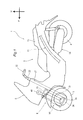
- FIG. 1 is a left side view showing an overall configuration of a three-wheeled vehicle 1 (saddle-ride type vehicle) according to an embodiment of the present invention.
- the three-wheeled vehicle 1 includes a vehicle body 2, left and right front wheels 3 disposed in front of the vehicle body 2, and one rear wheel 4 disposed behind the vehicle body 2.
- 1 indicates the forward direction of the three-wheeled vehicle 1
- the arrow U indicates the upward direction of the three-wheeled vehicle 1.
- the vehicle body 2 includes a body frame 11, a body cover 5, a handle 12, a seat 13, and a power unit 14.
- the vehicle body 2 includes a front wheel support mechanism 6 described later.
- the body frame 11 includes a head pipe 21.
- the head pipe 21 is disposed at the front portion of the three-wheeled vehicle 1.
- the head pipe 21 is connected to a main frame extending toward the rear of the vehicle and a down frame extending toward the vehicle lower side than the main frame.
- a steering shaft 22 is disposed in the head pipe 21.
- a handle 12 is rotatably connected to the head pipe 21 on the upper side of the steering shaft 22.
- a front wheel support mechanism 6 to be described later is connected to the head pipe 21 on the front side of the vehicle.
- the steering shaft 22 is connected to a left knuckle arm 31 and a right knuckle arm 32 of a front wheel support mechanism 6 which will be described later, although not particularly illustrated.
- the left and right front wheels 3 are rotatably supported by the left knuckle arm 31 and the right knuckle arm 32. Therefore, by rotating the steering shaft 22, the left and right front wheels 3 can be rotated in a top view.
- the vehicle body frame 11 having the above-described configuration is covered with a vehicle body cover 5.
- the vehicle body cover 5 is made of, for example, a resin material. Description of the detailed configuration of the vehicle body cover 5 is omitted.
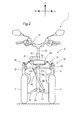
- the left and right front wheels 3 are rotatably supported by the left and right knuckle arms 31 and 32 of the front wheel support mechanism 6 as shown in FIG. That is, the left and right front wheels 3 are arranged on both the left and right sides of the front wheel support mechanism 6 so as to sandwich the front wheel support mechanism 6 connected to the head pipe 21 as described above.
- the rear wheel 4 has the same configuration as the rear wheel of a conventional motorcycle, description thereof is omitted. Further, the configuration of the power unit 14 including the engine, the driving force transmission device, and the like is the same as the configuration of the power unit of the conventional motorcycle, and thus detailed description thereof is omitted.
- the front wheel support mechanism 6 includes a link mechanism 30, a suspension 40, and a damper mechanism 50.
- the link mechanism 30 is rotatably supported with respect to the head pipe 21 as viewed from the front of the vehicle. Further, left and right front wheels 3 are attached to the left and right sides of the link mechanism 30 as viewed from above the vehicle. That is, the link mechanism 30 has a link structure that connects the left and right front wheels 3 and the head pipe 21.
- the suspension 40 is attached to the link mechanism 30 so as to attenuate the in-phase vibration generated in the left and right front wheels 3.
- the damper mechanism 50 is attached to the link mechanism 30 so as to attenuate the antiphase vibration generated in the left and right front wheels 3. The configuration related to the suspension 40 and the damper mechanism 50 will be described later.
- the link mechanism 30 includes left and right knuckle arms 31 and 32 positioned on the left and right sides of the vehicle, an upper arm 33 that connects the upper portions of the left and right knuckle arms 31 and 32 to the head pipe 21, and lower portions of the left and right knuckle arms 31 and 32. And a lower arm 34 connected to the head pipe 21.
- the left and right knuckle arms 31 and 32 are connected to the left and right front wheels 3, respectively. That is, the left and right front wheels 3 are rotatably supported at the lower ends of the left and right knuckle arms 31 and 32, respectively.
- the left knuckle arm 31 and the right knuckle arm 32 have substantially symmetrical shapes. Further, the left knuckle arm 31 and the right knuckle arm 32 are also symmetric with respect to the front wheel 3, the upper arm 33, and the lower arm 34. Therefore, in the following description, only the left knuckle arm 31 will be described.
- the left knuckle arm 31 extends in the vertical direction, and has a bent portion 31a that is bent so as to protrude toward the inside of the vehicle at the upper and lower central portions.
- the left knuckle arm 31 is rotatably connected to the upper arm 33 above the bent portion 31a.
- the left knuckle arm 31 is arranged so that the bent portion 31a straddles the inner side in the vehicle width direction of the tire of the front wheel 3 in the radial direction.
- the axle 3a (refer FIG. 1) of the front wheel 3 is rotatably connected below the bending part 31a of the left knuckle arm 31.
- the rubber-made tire is engage
- reference numeral 32 a is a bent portion provided on the right knuckle arm 32. Similarly to the bent portion 31a of the left knuckle arm 31, the bent portion 32a is also positioned so as to straddle the inner side in the vehicle width direction of the tire of the front wheel 3 in the radial direction.
- the upper arm 33 includes an upper left arm 35 that is rotatably connected to the left knuckle arm 31 and an upper right arm 36 that is rotatably connected to the right knuckle arm 32.
- the upper left arm 35 and the upper right arm 36 are rotatably connected to the head pipe 21, respectively.
- the upper left arm 35 and the upper right arm 36 rotate independently of the head pipe 21 and also rotate with respect to the left and right knuckle arms 31 and 32.
- the lower arm 34 includes a lower left arm 37 that is rotatably connected to the left knuckle arm 31 and a lower right arm 38 that is rotatably connected to the right knuckle arm 32. Similar to the upper left arm 35 and the upper right arm 36 described above, the lower left arm 37 and the lower right arm 38 are rotatably connected to the head pipe 21, respectively. Accordingly, the lower left arm 37 and the lower right arm 38 rotate independently of the head pipe 21 and also rotate with respect to the left and right knuckle arms 31 and 32.
- the link mechanism 30 of the present embodiment has a so-called double wishbone configuration in which the arms 35 to 38 move up and down independently in the upper and lower arms 33 and 34.
- a suspension 40 is attached to the upper side of the upper arm 33 constituting a part of the link mechanism 30 so as to connect the upper left arm 35 and the upper right arm 36. As shown in FIG. 2, the suspension 40 is disposed substantially parallel to the upper arm 33.
- the suspension 40 includes a columnar piston 41 and a cylindrical cylinder 42.
- the piston 41 has a piston body that divides the internal space of the cylinder 42 into two at one end in the longitudinal direction of the piston rod.
- the piston 41 is configured such that a piston main body provided at one end in the longitudinal direction is positioned in the cylinder 42 and is movable in the cylinder axis direction in the cylinder 42.
- the cylinder 42 is filled with hydraulic oil (fluid). When the piston 41 moves in the cylinder 42, a damping force is obtained by the suspension 40.
- the other end of the piston 41 located outside the cylinder 42 is rotatably connected to the upper right arm 36.
- the cylinder 42 is rotatably connected to the upper left arm 35 on the side opposite to the side on which the piston 41 is inserted.
- the piston 41 of the suspension 40 moves relative to the cylinder 42 in accordance with the relative displacement between the upper left arm 35 and the upper right arm 36. Therefore, the suspension 40 can attenuate vibrations that cause relative displacement in the upper left arm 35 and the upper right arm 36. For example, when vibrations having the same phase occur in the upper left arm 35 and the upper right arm 36, the vibration can be attenuated by the suspension 40.
- a damper mechanism 50 is attached between the upper arm 33 and the lower arm 34 so as to connect the upper right arm 36 of the upper arm 33 and the lower left arm 37 of the lower arm 34. That is, the damper mechanism 50 is disposed so as to intersect the head pipe 21 with respect to the substantially rectangular link mechanism 30 when viewed from the front of the vehicle.
- the damper mechanism 50 is a so-called through rod type damper in which a piston 51 passes through a cylindrical cylinder 52, as will be described in detail later.
- One end of the piston 51 of the damper mechanism 50 is rotatably connected to the upper right arm 36 of the upper arm 33.
- An end of the cylinder 52 opposite to the one end is rotatably connected to the lower left arm 37 of the lower arm 34.
- the damper mechanism 50 is disposed on the vehicle front side with respect to the head pipe 21.
- the damper mechanism 50 functions as a lock that prevents the head pipe 21 from falling by locking its operation as will be described later, and vibrations that cause relative displacement between the upper right arm 36 and the lower left arm 37 (that is, , Anti-phase vibration) can be attenuated.
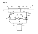
- the damper mechanism 50 includes a piston 62 and a cylinder 64.
- the piston 62 includes a piston main body 62A and a piston rod 62B.
- the piston main body 62A is disposed at the axially central portion of the piston rod 62B.
- the piston main body 62 ⁇ / b> A is disposed so as to be movable in the cylinder 64.
- the piston rod 62B is disposed so as to penetrate the cylinder 64 in the axial direction. That is, the damper mechanism 50 is a so-called through rod type damper.
- the hydraulic oil is accommodated in the cylinder 64.
- the cylinder 64 is partitioned into two spaces (a first space 66A and a second space 66B) by the piston body 62A.
- the first space 66A and the second space 66B are connected to each other by an attenuation circuit 68. Therefore, the hydraulic oil can move between the first space 66A and the second space 66B via the attenuation circuit 68.
- the attenuation circuit 68 includes four flow paths 70A, 70B, 70C, and 70D, two flow rate adjustment units 72A and 72B, and one temperature compensation chamber 74.
- the flow rate adjustment unit 72A is connected to the first space 66A via the flow path 70A.
- the flow rate adjusting unit 72A is connected to the flow rate adjusting unit 72B via the flow path 70B.
- the flow rate adjustment unit 72B is connected to the second space 66B via the flow path 70C.
- the temperature compensation chamber 74 is connected to the flow path 70B via the flow path 70D.
- the flow rate adjusting units 72A and 72B each include a valve body and a spring.
- the valve body is disposed at a position where the flow path in the switching valve 76 is closed by the biasing force of the spring.
- hydraulic fluid is prevented from flowing through the damping circuit 66. That is, the operation of the damper mechanism 50 is restricted.
- the operation of the link mechanism 36 is restricted. That is, the link mechanism 36 is locked.
- the actuator 78 is, for example, a motor.
- the actuator 78 moves the valve body against the biasing force of the spring.
- the valve body is disposed at a position where the flow paths in the flow rate adjustment units 72A and 72B are not blocked. Therefore, the hydraulic oil is allowed to flow in the attenuation circuit 66. That is, the operation of the damper mechanism 50 is allowed.
- the vibration is attenuated. For example, when anti-phase vibration occurs in the lower left arm 44L and the upper right arm 42R, that is, when anti-phase vibration occurs in the pair of front wheels 14L and 14R, the vibration is attenuated by the damper mechanism 50.
- the operation of the damper mechanism 50 is permitted, the operation of the link mechanism 36 is permitted. That is, the link mechanism is unlocked.
- the lock mechanism 80 is realized including the damper mechanism 50, the attenuation circuit 66, and the actuator 78.
- the relief valve 82 is arranged in parallel with the flow rate adjustment unit 72A.
- the relief valve 82 prevents the internal pressure of the cylinder 64 from increasing when the operation of the damper mechanism 50 is restricted.
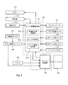
- the lock mechanism control unit 101 is provided, for example, in the control device 100 that controls the engine 14a and the like. That is, the control device 100 includes a lock mechanism control unit 101 that controls the operation of the damper mechanism 50 by the lock mechanism 80, and an engine control unit 102 that controls the drive of the engine 14a. In the control device 100, signals can be exchanged between the lock mechanism control unit 101 and the engine control unit 102.
- the lock mechanism control unit 101 is configured such that the vehicle speed, the vehicle speed change rate, and the throttle opening degree of the three-wheeled vehicle 1 are all equal to or less than the threshold value of the lock condition, and an instruction switch 103 (instruction SW, input instruction unit) provided on the handle 12 is used.
- instruction SW input instruction unit
- the damper mechanism 50 is brought into a locked state.
- the lock mechanism control unit 101 releases the lock of the damper mechanism 50 when at least one of the vehicle speed, the vehicle speed change rate, and the throttle opening of the three-wheeled vehicle 1 exceeds the threshold value of the unlock condition.
- the lock mechanism control unit 101 receives an instruction signal output from the instruction switch 103, a vehicle speed signal output from the wheel speed sensor 104 (vehicle speed detection unit), and a throttle position sensor 105 (TPS, throttle opening detection unit).
- the output throttle opening signal is input.
- the vehicle speed signal output from the wheel speed sensor 104 is once input to the ABS control unit 106 and then input to the lock mechanism control unit 101.
- the lock mechanism control unit 101 calculates a vehicle speed change rate based on the input vehicle speed signal.
- the throttle opening signal output from the throttle position sensor 105 is input to the control device 100 because it is used for control of the engine control unit 102.
- the lock mechanism control unit 101 receives signals output from the valve position sensor 107, the left arm angle sensor 108, and the right arm angle sensor 109, respectively.
- the valve position sensor 107 detects the position of the valve body in the flow rate adjustment units 72A and 72B of the damper mechanism 50.
- the position of the valve body detected by the valve position sensor 107 is used for opening / closing control of the flow paths in the flow rate adjusting units 72A and 72B.
- FIG. 4 only one valve position sensor 107 is illustrated, but in reality, one valve position sensor 107 is provided for one flow rate adjusting unit.
- the left arm angle sensor 108 detects the inclination of the upper left arm 35 and the lower left arm 37.
- the right arm angle sensor 109 detects the inclination of the upper right arm 36 and the lower right arm 38.
- the inclination of each arm detected by the left arm angle sensor 108 and the right arm angle sensor 109 is used, for example, when restricting locking or unlocking of the damper mechanism 50.
- a command signal output from the parking switch 110 (parking SW) is also input to the lock mechanism control unit 101.
- the lock mechanism control unit 101 causes the lock mechanism 80 to lock the damper mechanism 50. Thereby, the operation of the link mechanism 30 is restricted.
- the lock mechanism control unit 101 outputs a drive signal to the actuator 53 of the attenuation circuit 55. As will be described later, this drive signal is output from the lock mechanism control unit 101 when the damper mechanism 50 is switched to the locked state or the unlocked state. Further, the lock mechanism control unit 101 sends a signal to the buzzer 111 and the display unit 112 when the damper mechanism 50 is switched to the locked state or the unlocked state, or when waiting for the output of the instruction signal from the instruction switch 103. Is output.
- the lock mechanism control unit 101 includes a vehicle speed change rate acquisition unit 101a, a lock determination unit 101b, and an unlock determination unit 101c.
- the vehicle speed change rate acquisition unit 101 a calculates the vehicle speed change rate using the vehicle speed input from the wheel speed sensor 104 via the ABS control unit 106.
- the lock determination unit 101b generates a drive signal that causes the damper mechanism 50 to be locked when the three-wheeled vehicle 1 satisfies a predetermined lock condition.
- the unlock determination unit 101c generates a drive signal that puts the damper mechanism 50 into the unlock state when the three-wheeled vehicle 1 satisfies a predetermined unlock condition. Details of the lock condition and the lock release condition will be described later.
- the vehicle speed change rate acquisition unit 101a calculates the vehicle speed change rate using the vehicle speed output from the wheel speed sensor 104. Specifically, the vehicle speed change rate acquisition unit 101a obtains a difference between the vehicle speed detected by the wheel speed sensor 104 at the first time and the vehicle speed detected by the wheel speed sensor 104 at the second time, and calculates the difference. Output as vehicle speed change rate.
- the time difference between the first time and the second time may be a unit time or a predetermined time interval.
- the vehicle speed change rate acquisition unit 101a may be configured to differentiate the vehicle speed output from the wheel speed sensor 104 to obtain acceleration. That is, the vehicle speed change rate acquisition unit 101a may have any configuration as long as the vehicle speed change with respect to the time change can be calculated.
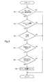
- step SA1 it is determined whether or not the damper mechanism 50 is in the unlocked state. Whether or not the lock is released is determined according to the position of the valve body in the flow rate adjustment units 72A and 72B detected by the valve position sensor 107.
- step SA1 it is determined that the damper mechanism 50 is not in the unlocked state, that is, in the locked state (in the case of NO), the flow is finished as it is (end).
- step SA1 determines whether the damper mechanism 50 is in the unlocked state. If it is determined in step SA1 that the damper mechanism 50 is in the unlocked state (in the case of YES), the process proceeds to step SA2 to determine whether the throttle opening is zero. Whether or not the throttle opening is zero is determined based on the throttle opening signal detected by the throttle position sensor 105. Note that the throttle opening being zero includes not only zero but also a throttle opening that is low enough not to give driving force to the vehicle. Further, in step SA2, whether or not the throttle opening is zero may be determined, and it may be determined whether or not the throttle opening is lower than a threshold that does not give driving force to the vehicle.
- step SA2 If it is determined in step SA2 that the throttle opening is not zero (in the case of NO), the flow is finished as it is (end). On the other hand, when it is determined in step SA2 that the throttle opening is zero (in the case of YES), the process proceeds to subsequent step SA3 to determine whether the vehicle speed is equal to or less than the threshold value P.
- This threshold value P is set to a vehicle speed lower than that during normal traveling, for example, immediately before the three-wheeled vehicle 1 stops.
- step SA3 If it is determined in step SA3 that the vehicle speed is greater than the threshold value P (in the case of NO), the flow is terminated as it is (end). On the other hand, when it is determined in step SA3 that the vehicle speed is equal to or less than the threshold value P (in the case of YES), the process proceeds to subsequent step SA4 to determine whether the vehicle speed change rate of the vehicle is equal to or less than the threshold value Q.
- This threshold value Q is set to a value lower than that during normal traveling, for example, immediately before the three-wheeled vehicle 1 stops.
- step SA4 If it is determined in step SA4 that the vehicle speed change rate is greater than the threshold value Q (in the case of NO), the flow is terminated as it is (end). On the other hand, when it is determined in step SA4 that the vehicle speed change rate is equal to or less than the threshold value Q (in the case of YES), the process proceeds to the subsequent step SA5 to determine whether there is an input instruction to the instruction switch 103. The presence / absence of an input instruction to the instruction switch 103 is determined by detecting an instruction signal output from the instruction switch 103.
- step SA5 If it is determined in step SA5 that there is no input instruction to the instruction switch 103 (in the case of NO), the flow is finished as it is (end). On the other hand, when it is determined in step SA5 that there is an input instruction to the instruction switch 103 (in the case of YES), the process proceeds to step SA6, and a drive signal for locking the damper mechanism 50 is generated.
- the instruction switch 103 is configured to continue outputting the instruction signal while the switch is input. Therefore, even when the input instruction to the instruction switch 103 is continued, the throttle opening, the vehicle speed, and the vehicle speed change rate satisfy the lock condition (in the case of YES in steps SA2 to SA4), the process proceeds to step SA5. It determines with YES and progresses to step SA6. Therefore, after the driver confirms that the throttle opening degree, the vehicle speed, and the vehicle speed change rate satisfy the lock condition, the damper mechanism 50 is quickly brought into the locked state as compared with the case where the input instruction is given to the instruction switch 103. can do.
- the lock mechanism control unit 101 has received an input instruction to the instruction switch 103 with the throttle opening being zero, the vehicle speed and the vehicle speed change rate being equal to or less than the threshold values. In this case, the damper mechanism 50 is brought into a locked state.
- the damper mechanism 50 is brought into the locked state, so that the vehicle is more reliably determined to be immediately before the stop. Only in this case, the damper mechanism 50 can be locked. Therefore, with the above-described configuration, the link mechanism 30 can be quickly locked immediately before the vehicle stops.
- the vehicle speed change rate is also the lock condition. Unless the condition is satisfied, the damper mechanism 50 is not locked. Thereby, when the three-wheeled vehicle 1 starts on a downhill, it can prevent more reliably that the link mechanism 30 is locked.
- the damper mechanism 50 when the damper mechanism 50 is locked by the lock mechanism 80, an input instruction by the instruction switch 103 is required. However, even if there is no input instruction by the instruction switch 103, the damper mechanism 50 may be locked by the lock mechanism 80 when the throttle opening degree, the vehicle speed, and the vehicle speed change rate satisfy the lock condition.
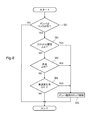
- step SB1 it is determined in step SB1 whether or not the damper mechanism 50 is in a locked state. Whether or not the damper mechanism 50 is in the locked state is determined according to the position of the valve body in the flow rate adjusting units 72A and 72B detected by the valve position sensor 107. When it is determined in step SB1 that the damper mechanism 50 is not in the locked state, that is, in the unlocked state (in the case of NO), the flow is finished as it is (end).
- step SB1 when it is determined in step SB1 that the damper mechanism 50 is in the locked state (in the case of YES), the process proceeds to step SB2, and it is determined whether or not the throttle opening is greater than or equal to the threshold value A. Whether or not the throttle opening is greater than or equal to the threshold value A is determined based on the throttle opening signal detected by the throttle position sensor 105.
- the threshold A is set to a throttle opening that can determine that the vehicle is accelerating, such as a throttle opening when the vehicle starts.
- step SB2 If it is determined in step SB2 that the throttle opening is greater than or equal to the threshold value A (in the case of YES), the process proceeds to step SB5 to generate a drive signal for bringing the damper mechanism 50 into the unlocked state. On the other hand, if it is determined in step SB2 that the throttle opening is smaller than the threshold value A (in the case of NO), the process proceeds to the subsequent step SB3 to determine whether the vehicle speed is equal to or higher than the threshold value B.
- the threshold value B is set to a predetermined vehicle speed at which it can be determined that the vehicle is traveling.
- step SB3 If it is determined in step SB3 that the vehicle speed is equal to or higher than the threshold value B (in the case of YES), the process proceeds to step SB5 to generate a drive signal for setting the damper mechanism 50 in the unlocked state. On the other hand, if it is determined in step SB3 that the vehicle speed is smaller than the threshold value B (in the case of NO), the process proceeds to the subsequent step SB4 to determine whether the vehicle speed change rate of the vehicle is greater than or equal to the threshold value C (predetermined value). judge.
- the threshold value C is set to a predetermined value that can be determined that the vehicle is accelerating for traveling.
- Step SB4 when it is determined that the vehicle speed change rate is equal to or higher than the threshold value C (in the case of YES), the process proceeds to Step SB5 to generate a drive signal for bringing the damper mechanism 50 into the unlocked state.
- Step SB4 when it is determined in step SB4 that the vehicle speed change rate is smaller than the threshold value C (in the case of NO), this flow is ended (END).
- step SB5 after generating a drive signal for bringing the damper mechanism 50 into the unlocked state, this flow is ended (END).
- the lock mechanism control unit 101 satisfies any one of the throttle opening degree equal to or greater than the threshold value A, the vehicle speed equal to or greater than the threshold value B, and the vehicle speed change rate equal to or greater than the threshold value C. In this case, the damper mechanism 50 is brought into the unlocked state.
- the damper mechanism 50 can be brought into the unlocked state more quickly than the configuration in which the damper mechanism 50 is brought into the unlocked state in consideration of the throttle opening and the vehicle speed.
- the damper mechanism 50 can be quickly and more reliably unlocked. That is, when the three-wheeled vehicle 1 starts on a downhill, the throttle opening degree and the vehicle speed are low, but it can be considered that the vehicle is gradually accelerating. Even in such a case, as described above, the damper mechanism 50 is brought into the unlocked state in consideration of the rate of change in the vehicle speed of the three-wheeled vehicle 1, so that the link mechanism 30 can be quickly and more reliably performed when the three-wheeled vehicle 1 starts. Can be unlocked.
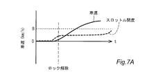
- FIG. 7A shows the timing for switching the damper mechanism 50 to the unlocked state when the three-wheeled vehicle 1 starts on a flat road.
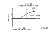
- FIG. 7B shows the timing for switching the damper mechanism 50 to the unlocked state when the three-wheeled vehicle 1 starts on a downhill.
- the lock mechanism control unit 101 having the above-described configuration can detect the start of the three-wheeled vehicle 1 quickly and more reliably even on a downhill than when the throttle opening and the vehicle speed are taken into consideration. Therefore, the damper mechanism 50 can be switched to the unlocked state quickly and more reliably according to the start of the three-wheeled vehicle 1.
- the lock mechanism control 101 determines that any one of the throttle opening, the vehicle speed, and the vehicle speed change rate satisfies the lock release condition (in the case of YES in any of steps SB2 to SB4). Then, the damper mechanism 50 is switched to the unlocked state. However, the lock mechanism control unit 101 switches the damper mechanism 50 to the unlocked state according to the input instruction of the instruction switch 103 even when any of the throttle opening degree, the vehicle speed, and the vehicle speed change rate does not satisfy the unlocking condition. It may be configured.
- the lock mechanism 80 that locks the link mechanism 30 by the lock mechanism 80 and the lock mechanism control that controls the lock mechanism 30 to be unlocked by the lock mechanism 80.
- the lock mechanism control unit 101 includes the vehicle speed detected by the wheel speed sensor 104 and the vehicle speed change rate acquired by the vehicle speed change rate acquisition unit 101a when the link mechanism 30 is locked by the lock mechanism 80. When at least one of the conditions satisfies the unlocking condition, the link mechanism 30 is brought into the unlocked state by the locking mechanism 80.
- the link mechanism 30 when the lock of the link mechanism 30 is released, not only the vehicle speed but also the rate of change of the vehicle speed is taken into account, so that the start of the vehicle is detected more reliably and the link mechanism 30 is unlocked quickly. Can do. That is, when the vehicle speed is set to the unlock condition, it is conceivable that the threshold value is set to a large value to some extent so that the link mechanism 30 is not unlocked when the driver is pushing the vehicle. In this case, the lock of the link mechanism 30 is not released until the vehicle speed reaches the threshold value. On the other hand, by considering not only the vehicle speed but also the vehicle speed change rate as the lock release condition, the link mechanism 30 can be quickly unlocked when the vehicle speed change rate satisfies the lock release condition.
- the start of the vehicle can be accurately determined based on the vehicle speed change rate. Therefore, the lock of the link mechanism 30 can be quickly released even when the vehicle starts on a downhill.
- the link mechanism 30 can be unlocked more quickly when the vehicle starts, and the link mechanism 30 can be locked even when the vehicle starts downhill. It can be released quickly.
- the unlocking condition is when the vehicle speed change rate is equal to or higher than a predetermined value.
- the lock mechanism control unit is 30 is unlocked.
- the link mechanism 30 When the rate of change in vehicle speed is equal to or higher than a predetermined value, the link mechanism 30 is unlocked by the lock mechanism 80, so that the link mechanism 30 can be unlocked more reliably when the vehicle starts.
- the vehicle speed change rate acquisition unit 101a uses the difference between the vehicle speed detected by the wheel speed sensor 104 at the first time and the vehicle speed detected by the wheel speed sensor 104 at the second time as the vehicle speed change rate. Output. Thereby, compared with the case where the vehicle speed is differentiated to obtain the vehicle speed change rate, the vehicle speed change rate can be easily obtained.
- the vehicle speed change rate acquisition unit 101a may output a differential value of the vehicle speed detected by the vehicle speed detection unit as the vehicle speed change rate.
- the three-wheel vehicle 1 further includes a throttle position sensor 105 that detects the throttle opening of the engine 14a.
- the lock mechanism control unit 101 performs the link mechanism by the lock mechanism 80. 30 is unlocked.
- the threshold value is set to a large value to some extent so that the lock is not released when the driver is pushing the vehicle.
- the lock of the link mechanism 30 is not released because the vehicle speed has not reached the threshold even though the vehicle has started running by increasing the engine speed by operating the accelerator grip of the driver. is there.
- the link mechanism 30 can be unlocked when the driver operates the accelerator grip. Therefore, it is possible to make it difficult for the link mechanism 30 to be unlocked even when the vehicle is traveling.
- the lock can be released quickly before the speed change rate increases at the time of start.
- the three-wheel vehicle 1 further includes a throttle position sensor 105 that detects the throttle opening of the engine 14a.
- the lock mechanism control unit 101 is acquired by the link opening 30 being unlocked and the throttle opening detected by the throttle position sensor 105, the vehicle speed detected by the wheel speed sensor 104, and the vehicle speed change rate acquisition unit 101a. When the vehicle speed change rate thus satisfied satisfies the lock condition, the link mechanism 30 is locked by the lock mechanism 80.
- the link mechanism 30 Only when the throttle opening, the vehicle speed, and the vehicle speed change rate all satisfy the lock condition, the link mechanism 30 is brought into the locked state so that the vehicle is more reliably determined to be immediately before stopping. 30 is locked. Therefore, with the above-described configuration, the link mechanism 30 can be quickly locked immediately before the vehicle stops. Further, with the above-described configuration, for example, when the vehicle speed of the three-wheeled vehicle 1 is gradually increasing on a downhill, even if the throttle opening and the vehicle speed satisfy the lock condition, the vehicle speed change rate is also the lock condition. Unless the condition is satisfied, the link mechanism 30 is not locked. This can more reliably prevent the link mechanism 30 from being locked when the vehicle starts on a downhill.
- the three-wheeled vehicle 1 further includes an instruction switch 103 that outputs an instruction signal that instructs the lock mechanism control unit 101 to unlock the link mechanism 30 by the lock mechanism 80.
- the lock mechanism control unit 101 causes the link mechanism 30 to be unlocked by the lock mechanism 80 when the link mechanism 30 is in the locked state.
- the lock mechanism 80 can unlock the link mechanism 30 according to the instruction signal output from the instruction switch 103. Accordingly, the lock mechanism 80 can be easily unlocked by the lock mechanism 80.
- the three-wheeled vehicle 1 further includes an instruction switch 103 that outputs an instruction signal that instructs the lock mechanism control unit 101 to lock the link mechanism 30 by the lock mechanism 80.
- the lock mechanism control unit 101 does not satisfy the lock condition for the change rate of the vehicle speed, the throttle opening degree, and the vehicle speed.
- the link mechanism 30 is brought into the locked state by the lock mechanism 80.
- the link mechanism 30 can be locked. That is, when the driver gives an input instruction using the instruction switch 103 in advance, the link mechanism 30 can be locked when each value satisfies the lock condition. Therefore, with the above-described configuration, the link mechanism 30 can be brought into the locked state more quickly than in the case where an input instruction is given by the instruction switch 103 after confirming that each value satisfies the lock condition.
- the three-wheeled vehicle 1 further includes a damper mechanism 50 capable of attenuating the antiphase vibration generated in the left and right front wheels 3.
- the lock mechanism 80 is configured to be able to lock the operation of the damper mechanism 50.
- the lock mechanism 80 that locks the operation of the link mechanism 30 can be configured by using the damper mechanism 50 that attenuates the anti-phase vibration generated in the left and right front wheels 3. Therefore, since it is not necessary to provide a separate locking mechanism, a compact and inexpensive three-wheeled vehicle 1 can be realized.
- the damper mechanism 50 the left damper 110, and the right damper 120
- so-called through rod type dampers in which the piston rod 51a penetrates both ends of the cylinder 52 are used.
- the damper mechanism may have a configuration other than the through rod type.
- the left and right arms respectively connected to the left knuckle arm 31 and the right knuckle arm 32 are separate members, and each arm is rotatably connected to the head pipe 21.
- This is a so-called double wishbone link mechanism.
- the link mechanism may be a link mechanism of any configuration such as a so-called parallel link mechanism in which the left knuckle arm 31 and the right knuckle arm 32 are connected by a connecting member that extends to the side of the vehicle.
- the damper mechanism 50 is provided between the lower left arm 37 and the upper right arm 36 of the link mechanism 30.
- the damper mechanism 50 is located between the upper left arm 35 and the lower right arm 38, between the other arms, or between the arm and the vehicle body, as long as it can attenuate the antiphase vibration generated in the left and right front wheels 3. It may be provided between the frame 11.
- the lock mechanism control unit 101 is configured to perform lock control or lock release control using the throttle opening signal output from the throttle position sensor 105.
- the lock mechanism control unit 101 may perform lock control or lock release control using any value as long as the value corresponds to the throttle opening, such as the detection result of the rotation angle of the accelerator grip. Therefore, the throttle opening detection unit may be configured other than the throttle position sensor as long as it can detect a value corresponding to the throttle opening.
- the vehicle speed change rate acquisition unit 101a of the lock mechanism control unit 101 calculates the vehicle speed change rate.
- the acceleration of the vehicle may be detected, and the lock mechanism control unit 101 may perform lock control or unlock control using the detection result.
- the wheel speed sensor 104 is used to detect the vehicle speed of the three-wheeled vehicle 1.
- a sensor other than the wheel speed sensor 104 may be used as long as the vehicle speed of the three-wheeled vehicle 1 can be detected.
Abstract
Description
図1は、本発明の実施形態に係る三輪車両1(鞍乗型車両)の全体構成を示す左側面図である。この三輪車両1は、車両本体2、車両本体2の前方に配置された左右の前輪3、及び、車両本体2の後方に配置された一つの後輪4を備える。なお、図1中の矢印Fは、三輪車両1の前方向を示し、矢印Uは三輪車両1の上方向を示す。 <Overall configuration of tricycle>
FIG. 1 is a left side view showing an overall configuration of a three-wheeled vehicle 1 (saddle-ride type vehicle) according to an embodiment of the present invention. The three-
次に、左右の前輪3をヘッドパイプ21に対して支持する前輪支持機構6の構成について、図1及び図2を用いて詳細に説明する。 <Front wheel support mechanism>
Next, the configuration of the front
図3に示すように、ダンパ機構50は、ピストン62と、シリンダ64とを備える。 <Damper mechanism>
As shown in FIG. 3, the
上述のような構成を有するダンパ機構50の動作をロック機構80によって制御するためのロック機構制御部101について、図4を用いて以下で説明する。 <Lock mechanism controller>
A lock
次に、上述の構成を有するロック機構制御部101によってダンパ機構50をロック状態に切り替えるロック制御について、図5のフローを用いて以下で説明する。 <Lock control>
Next, lock control for switching the
次に、上述の構成を有するロック機構制御部101によってダンパ機構50をロック解除状態に切り替えるロック解除制御について、図6のフローを用いて以下で説明する。 <Unlock control>
Next, unlocking control for switching the
以上、本発明の実施の形態を説明したが、上述した実施の形態は本発明を実施するための例示に過ぎない。よって、本発明は上述した実施の形態に限定されることなく、その趣旨を逸脱しない範囲内で上述した実施の形態を適宜変形して実施することが可能である。 (Other embodiments)
While the embodiments of the present invention have been described above, the above-described embodiments are merely examples for carrying out the present invention. Therefore, the present invention is not limited to the above-described embodiment, and can be implemented by appropriately modifying the above-described embodiment without departing from the spirit thereof.
Claims (8)
- エンジンと、
車体フレームと、
左右の前輪と、
前記左右の前輪を前記車体フレームに対して接続するリンク機構と、
前記リンク機構の動作を規制することにより前記リンク機構をロック状態にする一方、前記リンク機構の動作を許容することにより前記リンク機構をロック解除状態にするロック機構と、
前記ロック機構による前記リンク機構のロック及びロック解除を制御するロック機構制御部と、
車速を検出する車速検出部と、
前記車速の変化率を取得する車速変化率取得部とを備え、
前記ロック機構制御部は、前記ロック機構によって前記リンク機構がロック状態であり、且つ、前記車速検出部によって検出された車速、及び、前記車速変化率取得部によって取得された車速変化率のうち少なくとも一方がロック解除条件を満たしている場合に、前記ロック機構によって前記リンク機構をロック解除状態にする、鞍乗型車両。 Engine,
Body frame,
Left and right front wheels,
A link mechanism for connecting the left and right front wheels to the body frame;
A lock mechanism that locks the link mechanism by restricting the operation of the link mechanism, and that locks the link mechanism by allowing the link mechanism to operate;
A lock mechanism control unit that controls locking and unlocking of the link mechanism by the lock mechanism;
A vehicle speed detector for detecting the vehicle speed;
A vehicle speed change rate acquisition unit for acquiring the vehicle speed change rate;
The lock mechanism control unit includes at least one of a vehicle speed detected by the vehicle speed detection unit and a vehicle speed change rate acquired by the vehicle speed change rate acquisition unit when the link mechanism is locked by the lock mechanism. A straddle-type vehicle in which, when one of the lock release conditions is satisfied, the link mechanism is brought into an unlocked state by the lock mechanism. - 請求項1に記載の鞍乗型車両において、
前記ロック解除条件は、車速変化率が所定値以上の場合であり、
前記ロック機構制御部は、前記ロック機構によって前記リンク機構がロック状態であり、且つ、前記車速変化率取得部によって取得された車速変化率が前記所定値以上の場合に、前記ロック機構によって前記リンク機構をロック解除状態にする、鞍乗型車両。 The saddle riding type vehicle according to claim 1, wherein
The unlocking condition is when the vehicle speed change rate is a predetermined value or more,
When the link mechanism is locked by the lock mechanism and the vehicle speed change rate acquired by the vehicle speed change rate acquisition unit is greater than or equal to the predetermined value, the lock mechanism control unit is configured to link the link mechanism by the lock mechanism. A straddle-type vehicle whose mechanism is unlocked. - 請求項1または2に記載の鞍乗型車両において、
前記車速変化率取得部は、前記車速検出部によって第1時間に検出された車速と前記車速検出部によって第2時間に検出された車速との差分、または前記車速検出部によって検出された車速の微分値を、前記車速変化率として出力する、鞍乗型車両。 The saddle riding type vehicle according to claim 1 or 2,
The vehicle speed change rate acquisition unit is configured to obtain a difference between a vehicle speed detected at a first time by the vehicle speed detection unit and a vehicle speed detected at a second time by the vehicle speed detection unit, or a vehicle speed detected by the vehicle speed detection unit. A straddle-type vehicle that outputs a differential value as the vehicle speed change rate. - 請求項1から3のいずれか一つに記載の鞍乗型車両において、
前記エンジンのスロットル開度に対応する値を検出するスロットル開度検出部をさらに備え、
前記ロック機構制御部は、前記ロック機構によって前記リンク機構がロック状態であり、且つ、前記スロットル開度検出部によって検出されたスロットル開度に対応する値がロック解除条件を満たしている場合に、前記ロック機構によって前記リンク機構をロック解除状態にする、鞍乗型車両。 The saddle riding type vehicle according to any one of claims 1 to 3,
A throttle opening detector for detecting a value corresponding to the throttle opening of the engine;
When the link mechanism is locked by the lock mechanism and the value corresponding to the throttle opening detected by the throttle opening detector satisfies the unlock condition, the lock mechanism controller A straddle-type vehicle in which the link mechanism is unlocked by the lock mechanism. - 請求項1に記載の鞍乗型車両において、
前記エンジンのスロットル開度に対応する値を検出するスロットル開度検出部をさらに備え、
前記ロック機構制御部は、前記リンク機構がロック解除状態であり、且つ、前記スロットル開度検出部によって検出されたスロットル開度に対応する値、前記車速検出部によって検出された車速、及び前記車速変化率取得部によって取得された車速変化率がそれぞれロック条件を満たしている場合に、前記ロック機構によって前記リンク機構をロック状態にする、鞍乗型車両。 The saddle riding type vehicle according to claim 1, wherein
A throttle opening detector for detecting a value corresponding to the throttle opening of the engine;
The lock mechanism control unit includes a value corresponding to a throttle opening detected by the throttle opening detection unit, a vehicle speed detected by the vehicle speed detection unit, and the vehicle speed when the link mechanism is unlocked. A straddle-type vehicle in which the link mechanism is brought into a locked state by the lock mechanism when vehicle speed change rates acquired by the change rate acquisition unit respectively satisfy a lock condition. - 請求項1に記載の鞍乗型車両において、
前記ロック機構制御部に対し、前記ロック機構による前記リンク機構のロック解除を指示する指示信号を出力する入力指示部をさらに備え、
前記ロック機構制御部は、前記入力指示部から指示信号が入力された際に、前記リンク機構がロック状態では前記ロック機構によって前記リンク機構をロック解除状態にする、鞍乗型車両。 The saddle riding type vehicle according to claim 1, wherein
An input instruction unit that outputs an instruction signal to instruct the lock mechanism control unit to unlock the link mechanism by the lock mechanism;
The lock mechanism control unit is a straddle-type vehicle that, when an instruction signal is input from the input instruction unit, causes the link mechanism to be unlocked by the lock mechanism when the link mechanism is in a locked state. - 請求項5に記載の鞍乗型車両において、
前記ロック機構制御部に対し、前記ロック機構による前記リンク機構のロックを指示する指示信号を出力する入力指示部をさらに備え、
前記ロック機構制御部は、前記リンク機構がロック解除状態で、前記入力指示部から指示信号が入力されている間に、前記車速の変化率、スロットル開度に対応する値及び車速がそれぞれ前記ロック条件を満たしていない状態から該ロック条件を満たした状態に変化した際に、前記ロック機構によって前記リンク機構をロック状態にする、鞍乗型車両。 The saddle riding type vehicle according to claim 5,
An input instruction unit that outputs an instruction signal that instructs the lock mechanism control unit to lock the link mechanism by the lock mechanism;
While the link mechanism is in the unlocked state and the instruction signal is input from the input instruction unit, the lock mechanism control unit is configured such that the vehicle speed change rate, the value corresponding to the throttle opening, and the vehicle speed are A straddle-type vehicle in which the link mechanism is locked by the lock mechanism when the lock condition is changed from a condition that does not satisfy the condition. - 請求項1から7のいずれか一つに記載の鞍乗型車両において、
前記左右の前輪に生じる逆位相の振動を減衰可能なダンパ機構をさらに備え、
前記ロック機構は、前記ダンパ機構の動作をロック可能に構成されている、鞍乗型車両。 The saddle riding type vehicle according to any one of claims 1 to 7,
Further comprising a damper mechanism capable of attenuating anti-phase vibrations generated in the left and right front wheels,
The lock mechanism is a straddle-type vehicle configured to be able to lock the operation of the damper mechanism.
Priority Applications (5)
| Application Number | Priority Date | Filing Date | Title |
|---|---|---|---|
| CA2943765A CA2943765C (en) | 2014-03-24 | 2015-03-16 | Saddle riding type vehicle with two front wheels and lockable linkage |
| ES15770430T ES2727622T3 (en) | 2014-03-24 | 2015-03-16 | Straddle Vehicle |
| EP15770430.5A EP3124366B1 (en) | 2014-03-24 | 2015-03-16 | Saddled vehicle |
| US15/128,467 US10668972B2 (en) | 2014-03-24 | 2015-03-16 | Saddle riding type vehicle |
| JP2016510258A JPWO2015146680A1 (en) | 2014-03-24 | 2015-03-16 | Saddle riding vehicle |
Applications Claiming Priority (2)
| Application Number | Priority Date | Filing Date | Title |
|---|---|---|---|
| JP2014-060199 | 2014-03-24 | ||
| JP2014060199 | 2014-03-24 |
Publications (1)
| Publication Number | Publication Date |
|---|---|
| WO2015146680A1 true WO2015146680A1 (en) | 2015-10-01 |
Family
ID=54195203
Family Applications (1)
| Application Number | Title | Priority Date | Filing Date |
|---|---|---|---|
| PCT/JP2015/057735 WO2015146680A1 (en) | 2014-03-24 | 2015-03-16 | Saddled vehicle |
Country Status (6)
| Country | Link |
|---|---|
| US (1) | US10668972B2 (en) |
| EP (1) | EP3124366B1 (en) |
| JP (1) | JPWO2015146680A1 (en) |
| CA (1) | CA2943765C (en) |
| ES (1) | ES2727622T3 (en) |
| WO (1) | WO2015146680A1 (en) |
Cited By (8)
| Publication number | Priority date | Publication date | Assignee | Title |
|---|---|---|---|---|
| WO2017086351A1 (en) * | 2015-11-20 | 2017-05-26 | ヤマハ発動機株式会社 | Leaning vehicle |
| WO2017086350A1 (en) * | 2015-11-20 | 2017-05-26 | ヤマハ発動機株式会社 | Leaning vehicle |
| EP3300999A1 (en) * | 2016-09-29 | 2018-04-04 | Honda Motor Co., Ltd. | Rocking control device for two front wheels rocking vehicle |
| JP2018052308A (en) * | 2016-09-29 | 2018-04-05 | 本田技研工業株式会社 | Swing control device of front two-wheel swing vehicle |
| WO2019098284A1 (en) * | 2017-11-17 | 2019-05-23 | ヤマハ発動機株式会社 | Leaning vehicle |
| JP2021506661A (en) * | 2017-12-21 | 2021-02-22 | ピアッジオ・エ・チ・ソチエタ・ペル・アツィオーニ | How to safely interfere with the tilting motion of a three-wheeled or four-wheeled tilted motor vehicle and a three-wheeled or four-wheeled tilted motor vehicle |
| US11014600B2 (en) | 2015-11-20 | 2021-05-25 | Yamaha Hatsudoki Kabushiki Kaisha | Leaning vehicle |
| US11173979B2 (en) | 2015-11-20 | 2021-11-16 | Yamaha Hatsudoki Kabushiki Kaisha | Leaning vehicle |
Families Citing this family (16)
| Publication number | Priority date | Publication date | Assignee | Title |
|---|---|---|---|---|
| ES2727606T3 (en) * | 2014-03-24 | 2019-10-17 | Yamaha Motor Co Ltd | Straddle Type Vehicle |
| WO2017082425A1 (en) * | 2015-11-13 | 2017-05-18 | ヤマハ発動機株式会社 | Leaning vehicle |
| CA3005012A1 (en) * | 2015-11-13 | 2017-05-18 | Yamaha Hatsudoki Kabushiki Kaisha | Leaning vehicle |
| ITUB20159521A1 (en) | 2015-12-28 | 2017-06-28 | Piaggio & C Spa | Rolling motor vehicle with roll control |
| CN106314609A (en) * | 2016-09-12 | 2017-01-11 | 北海和思科技有限公司 | Intelligent bicycle system and method |
| IT201600123275A1 (en) * | 2016-12-05 | 2018-06-05 | Piaggio & C Spa | Motorcycle with two steering front wheels and one steering with variable steering ratio |
| IT201600129502A1 (en) | 2016-12-21 | 2018-06-21 | Piaggio & C Spa | ADVANCED ROLLER MOTORCYCLE WITH ROLLI CONTROL |
| IT201600129491A1 (en) * | 2016-12-21 | 2018-06-21 | Piaggio & C Spa | ADVANCE OF ROLLANTE MOTORCYCLE WITH ROLLO BLOCK |
| IT201600129510A1 (en) | 2016-12-21 | 2018-06-21 | Piaggio & C Spa | ADVANCE OF ROLLANTE MOTORCYCLE WITH ROLLIO CONTROL |
| IT201600129489A1 (en) | 2016-12-21 | 2018-06-21 | Piaggio & C Spa | ADVANCE OF ROLLANTE MOTORCYCLE WITH ROLLO BLOCK |
| JP2018144697A (en) * | 2017-03-07 | 2018-09-20 | ヤマハ発動機株式会社 | vehicle |
| JP2018144698A (en) * | 2017-03-07 | 2018-09-20 | ヤマハ発動機株式会社 | vehicle |
| ES2845231T3 (en) * | 2017-05-19 | 2021-07-26 | Yamaha Motor Co Ltd | Leaning vehicle |
| CN111263721B (en) * | 2017-09-29 | 2021-09-24 | 本田技研工业株式会社 | Saddle-ride type electric vehicle |
| EP3828069B1 (en) * | 2018-08-30 | 2024-03-13 | Yamaha Hatsudoki Kabushiki Kaisha | Attitude control actuator unit and leaning vehicle |
| CN109693745B (en) * | 2018-12-29 | 2021-04-02 | 北京牛电信息技术有限责任公司 | Vehicle tilting device and method and vehicle |
Citations (7)
| Publication number | Priority date | Publication date | Assignee | Title |
|---|---|---|---|---|
| JP2009286266A (en) * | 2008-05-29 | 2009-12-10 | Yamaha Motor Co Ltd | Saddle type vehicle |
| JP2010184690A (en) * | 2009-02-13 | 2010-08-26 | Honda Motor Co Ltd | Power steering device of saddle-riding type vehicle |
| JP2011042199A (en) * | 2009-08-20 | 2011-03-03 | Equos Research Co Ltd | Vehicle |
| JP2012025370A (en) * | 2010-06-25 | 2012-02-09 | Equos Research Co Ltd | Vehicle |
| JP2012081784A (en) * | 2010-10-07 | 2012-04-26 | Toyota Motor Corp | Vehicle body tilting device |
| JP2013112234A (en) * | 2011-11-30 | 2013-06-10 | Equos Research Co Ltd | Vehicle |
| JP2013244763A (en) * | 2012-05-23 | 2013-12-09 | Aisin Seiki Co Ltd | Vehicle control apparatus, vehicle control method, and program |
Family Cites Families (43)
| Publication number | Priority date | Publication date | Assignee | Title |
|---|---|---|---|---|
| JPS60163752A (en) * | 1984-02-06 | 1985-08-26 | Yamaha Motor Co Ltd | Brake device of vehicle for running on wasteland |
| JPS60193880U (en) * | 1984-06-04 | 1985-12-24 | 本田技研工業株式会社 | Vehicle carrier device |
| JPS6218378A (en) * | 1985-07-17 | 1987-01-27 | 本田技研工業株式会社 | Rear fender device in saddling type car |
| US4787470A (en) * | 1986-06-30 | 1988-11-29 | Yamaha Hatsudoki Kabushiki Kaisha | Three wheel vehicle |
| JP2918116B2 (en) * | 1989-06-22 | 1999-07-12 | ヤマハ発動機株式会社 | Fuel supply structure of scooter type motorcycles and tricycles |
| US6268794B1 (en) * | 2000-01-21 | 2001-07-31 | Harley-Davidson Motor Company Group, Inc. | Integrated security, tip-over, and turn signal system |
| ITPN20000034A1 (en) * | 2000-06-02 | 2001-12-02 | Aprilia Spa | REFINEMENTS FOR VEHICLES HAVING TWO FRONT AND STEERING WHEELS AND AT LEAST ONE REAR DRIVE WHEEL |
| US6588529B2 (en) * | 2000-07-05 | 2003-07-08 | Yamaha Hatsudoki Kabishuki Kaisha | Body cover and structure for motorcycle |
| PT1363794E (en) * | 2001-02-27 | 2006-10-31 | Aprilia Spa | VEHICLE OF THREE WHEELS WITH SYSTEM OF SUSPENSION BASCULANTE |
| JP4287136B2 (en) * | 2002-12-20 | 2009-07-01 | 本田技研工業株式会社 | Vehicle suspension arrangement structure |
| ITMI20031108A1 (en) * | 2003-06-03 | 2004-12-04 | Piaggio & C Spa | THREE-WHEEL ROLLING VEHICLE WITH TWO STEERING FRONT WHEELS |
| US7669864B2 (en) * | 2003-10-21 | 2010-03-02 | Rodney Ian Rawlinson | Laterally-leaning four wheeled vehicle |
| ITMI20040172A1 (en) * | 2004-02-04 | 2004-05-04 | Piaggio & C Spa | VEHICLE SUSPENSION STOPPING DEVICE |
| ITMI20040171A1 (en) | 2004-02-04 | 2004-05-04 | Piaggio & C Spa | ANTI-ROLL DEVICE FOR VEHICLES |
| JP2006088894A (en) * | 2004-09-24 | 2006-04-06 | Yamaha Motor Co Ltd | Saddle ride type vehicle |
| JP2006341837A (en) | 2005-06-10 | 2006-12-21 | Piaggio & C Spa | Electronic control system for vehicle operation unit |
| US7648148B1 (en) * | 2005-07-06 | 2010-01-19 | Bombardier Recreational Products Inc. | Leaning vehicle with tilting front wheels and suspension therefor |
| JP2009509857A (en) * | 2005-09-30 | 2009-03-12 | ハーレー−ダビッドソン・モーター・カンパニー・グループ・インコーポレーテッド | Tilt suspension machine |
| JP4886319B2 (en) * | 2006-02-27 | 2012-02-29 | 本田技研工業株式会社 | Vehicle deceleration device |
| USD547242S1 (en) * | 2006-03-02 | 2007-07-24 | Piaggio & C. S.P.A. | Motorcycle |
| US20090107754A1 (en) * | 2007-10-31 | 2009-04-30 | Harley-Davidson Motor Company Group, Inc. | Vehicle having a detachable pulley mount |
| WO2009059099A2 (en) * | 2007-10-31 | 2009-05-07 | Vectrix Corporation | Lockable tilt system for a three-wheeled vehicle |
| USD598328S1 (en) * | 2008-05-12 | 2009-08-18 | Piaggio & C. S.P.A. | Motorcycle |
| JP5204637B2 (en) * | 2008-12-16 | 2013-06-05 | ヤマハ発動機株式会社 | Saddle riding vehicle |
| IT1401130B1 (en) * | 2010-07-16 | 2013-07-12 | Piaggio & C Spa | MOTORCYCLE SUSPENSION SYSTEM |
| JP5694788B2 (en) * | 2011-01-17 | 2015-04-01 | 本田技研工業株式会社 | Saddle riding vehicle |
| ITMI20111469A1 (en) * | 2011-08-01 | 2013-02-02 | Piaggio & C Spa | ADJUSTMENT SYSTEM FOR THE HEADLIGHTS OF A TILTING VEHICLE WITH A ROLLIO MECHANISM |
| CN202414056U (en) * | 2012-01-14 | 2012-09-05 | 于金君 | Inverted motor tricycle capable of tilting tricycle body |
| JP5889685B2 (en) * | 2012-03-22 | 2016-03-22 | 本田技研工業株式会社 | Canister layout for saddle-ride type vehicles |
| JP5969232B2 (en) * | 2012-03-22 | 2016-08-17 | 本田技研工業株式会社 | Radiator hose layout structure for saddle-ride type vehicles |
| FR2995255B1 (en) * | 2012-09-07 | 2014-09-19 | Lmed | FLOOR LINK SYSTEM FOR RECLINING VEHICLE, SUCH AS A TRICYCLE |
| JP6077883B2 (en) * | 2013-02-27 | 2017-02-08 | 本田技研工業株式会社 | Blinker cancellation device for vehicle |
| JP5775560B2 (en) * | 2013-12-06 | 2015-09-09 | 本田技研工業株式会社 | Saddle riding |
| JP2015113074A (en) * | 2013-12-13 | 2015-06-22 | ヤマハ発動機株式会社 | Saddle-riding type vehicle |
| WO2015115110A1 (en) * | 2014-01-31 | 2015-08-06 | ヤマハ発動機株式会社 | Vehicle |
| CN105377683B (en) * | 2014-01-31 | 2018-04-03 | 雅马哈发动机株式会社 | Vehicle |
| WO2015146653A1 (en) * | 2014-03-24 | 2015-10-01 | ヤマハ発動機株式会社 | Saddle-type vehicle |
| ES2727606T3 (en) * | 2014-03-24 | 2019-10-17 | Yamaha Motor Co Ltd | Straddle Type Vehicle |
| EP3124367B1 (en) * | 2014-03-24 | 2020-05-06 | Yamaha Hatsudoki Kabushiki Kaisha | Saddled vehicle |
| JP6369217B2 (en) * | 2014-08-20 | 2018-08-08 | スズキ株式会社 | Fuel cell motorcycle |
| JP6086889B2 (en) * | 2014-09-30 | 2017-03-01 | 本田技研工業株式会社 | Rear fuel tank |
| JP6413873B2 (en) * | 2015-03-24 | 2018-10-31 | スズキ株式会社 | Saddle type fuel cell vehicle |
| JP6450267B2 (en) * | 2015-06-23 | 2019-01-09 | 本田技研工業株式会社 | Moving body |
-
2015
- 2015-03-16 ES ES15770430T patent/ES2727622T3/en active Active
- 2015-03-16 EP EP15770430.5A patent/EP3124366B1/en active Active
- 2015-03-16 WO PCT/JP2015/057735 patent/WO2015146680A1/en active Application Filing
- 2015-03-16 JP JP2016510258A patent/JPWO2015146680A1/en active Pending
- 2015-03-16 CA CA2943765A patent/CA2943765C/en active Active
- 2015-03-16 US US15/128,467 patent/US10668972B2/en active Active
Patent Citations (7)
| Publication number | Priority date | Publication date | Assignee | Title |
|---|---|---|---|---|
| JP2009286266A (en) * | 2008-05-29 | 2009-12-10 | Yamaha Motor Co Ltd | Saddle type vehicle |
| JP2010184690A (en) * | 2009-02-13 | 2010-08-26 | Honda Motor Co Ltd | Power steering device of saddle-riding type vehicle |
| JP2011042199A (en) * | 2009-08-20 | 2011-03-03 | Equos Research Co Ltd | Vehicle |
| JP2012025370A (en) * | 2010-06-25 | 2012-02-09 | Equos Research Co Ltd | Vehicle |
| JP2012081784A (en) * | 2010-10-07 | 2012-04-26 | Toyota Motor Corp | Vehicle body tilting device |
| JP2013112234A (en) * | 2011-11-30 | 2013-06-10 | Equos Research Co Ltd | Vehicle |
| JP2013244763A (en) * | 2012-05-23 | 2013-12-09 | Aisin Seiki Co Ltd | Vehicle control apparatus, vehicle control method, and program |
Cited By (17)
| Publication number | Priority date | Publication date | Assignee | Title |
|---|---|---|---|---|
| WO2017086351A1 (en) * | 2015-11-20 | 2017-05-26 | ヤマハ発動機株式会社 | Leaning vehicle |
| WO2017086350A1 (en) * | 2015-11-20 | 2017-05-26 | ヤマハ発動機株式会社 | Leaning vehicle |
| US11173979B2 (en) | 2015-11-20 | 2021-11-16 | Yamaha Hatsudoki Kabushiki Kaisha | Leaning vehicle |
| US11014422B2 (en) | 2015-11-20 | 2021-05-25 | Yamaha Hatsudoki Kabushiki Kaisha | Leaning vehicle |
| US11014600B2 (en) | 2015-11-20 | 2021-05-25 | Yamaha Hatsudoki Kabushiki Kaisha | Leaning vehicle |
| EP3366558A4 (en) * | 2015-11-20 | 2019-01-02 | Yamaha Hatsudoki Kabushiki Kaisha | Leaning vehicle |
| US10696346B2 (en) | 2015-11-20 | 2020-06-30 | Yamaha Hatsudoki Kabushiki Kaisha | Leaning vehicle |
| US10632812B2 (en) | 2016-09-29 | 2020-04-28 | Honda Motor Co., Ltd. | Rocking control device for two front wheels rocking vehicle |
| US10596872B2 (en) | 2016-09-29 | 2020-03-24 | Honda Motor Co., Ltd. | Rocking control device for two front wheels rocking vehicle |
| JP2018052309A (en) * | 2016-09-29 | 2018-04-05 | 本田技研工業株式会社 | Swing control device of front two-wheel swing vehicle |
| JP2018052308A (en) * | 2016-09-29 | 2018-04-05 | 本田技研工業株式会社 | Swing control device of front two-wheel swing vehicle |
| EP3300999A1 (en) * | 2016-09-29 | 2018-04-04 | Honda Motor Co., Ltd. | Rocking control device for two front wheels rocking vehicle |
| WO2019098284A1 (en) * | 2017-11-17 | 2019-05-23 | ヤマハ発動機株式会社 | Leaning vehicle |
| JPWO2019098284A1 (en) * | 2017-11-17 | 2020-10-22 | ヤマハ発動機株式会社 | Lean vehicle |
| TWI721334B (en) * | 2017-11-17 | 2021-03-11 | 日商山葉發動機股份有限公司 | Tilting vehicle |
| JP2021506661A (en) * | 2017-12-21 | 2021-02-22 | ピアッジオ・エ・チ・ソチエタ・ペル・アツィオーニ | How to safely interfere with the tilting motion of a three-wheeled or four-wheeled tilted motor vehicle and a three-wheeled or four-wheeled tilted motor vehicle |
| JP7368356B2 (en) | 2017-12-21 | 2023-10-24 | ピアッジオ・エ・チ・ソチエタ・ペル・アツィオーニ | Three-wheeled or four-wheeled tipping motor vehicle and how to safely impede the tipping motion of a three- or four-wheeled tipping motorized vehicle |
Also Published As
| Publication number | Publication date |
|---|---|
| EP3124366A1 (en) | 2017-02-01 |
| EP3124366B1 (en) | 2019-05-08 |
| US20170106930A1 (en) | 2017-04-20 |
| JPWO2015146680A1 (en) | 2017-04-13 |
| CA2943765A1 (en) | 2015-10-01 |
| US10668972B2 (en) | 2020-06-02 |
| EP3124366A4 (en) | 2017-07-26 |
| CA2943765C (en) | 2020-01-21 |
| ES2727622T3 (en) | 2019-10-17 |
Similar Documents
| Publication | Publication Date | Title |
|---|---|---|
| WO2015146680A1 (en) | Saddled vehicle | |
| JP6074543B2 (en) | Saddle riding vehicle | |
| WO2015146679A1 (en) | Saddle-type vehicle | |
| CA2943760C (en) | Saddle riding type vehicle with two front wheels and lockable linkage | |
| EP3164277B1 (en) | Electronic braking device of the tilting system of a vehicle with three or more tilting wheels | |
| EP3157805B1 (en) | Improved control system of the trim of vehicles with more than two wheels | |
| WO2012153526A1 (en) | Steering-damper control device and straddled vehicle provided therewith | |
| KR20040052400A (en) | a steering wheel vibration protecting device for vehicles |
Legal Events
| Date | Code | Title | Description |
|---|---|---|---|
| 121 | Ep: the epo has been informed by wipo that ep was designated in this application |
Ref document number: 15770430 Country of ref document: EP Kind code of ref document: A1 |
|
| ENP | Entry into the national phase |
Ref document number: 2016510258 Country of ref document: JP Kind code of ref document: A |
|
| ENP | Entry into the national phase |
Ref document number: 2943765 Country of ref document: CA |
|
| REEP | Request for entry into the european phase |
Ref document number: 2015770430 Country of ref document: EP |
|
| WWE | Wipo information: entry into national phase |
Ref document number: 15128467 Country of ref document: US Ref document number: IDP00201606365 Country of ref document: ID Ref document number: 2015770430 Country of ref document: EP |
|
| NENP | Non-entry into the national phase |
Ref country code: DE |