WO2015146406A1 - 管継手 - Google Patents
管継手 Download PDFInfo
- Publication number
- WO2015146406A1 WO2015146406A1 PCT/JP2015/054917 JP2015054917W WO2015146406A1 WO 2015146406 A1 WO2015146406 A1 WO 2015146406A1 JP 2015054917 W JP2015054917 W JP 2015054917W WO 2015146406 A1 WO2015146406 A1 WO 2015146406A1
- Authority
- WO
- WIPO (PCT)
- Prior art keywords
- pipe joint
- galling
- male screw
- external device
- screw
- Prior art date
- Legal status (The legal status is an assumption and is not a legal conclusion. Google has not performed a legal analysis and makes no representation as to the accuracy of the status listed.)
- Ceased
Links
Images

Classifications
-
- F—MECHANICAL ENGINEERING; LIGHTING; HEATING; WEAPONS; BLASTING
- F16—ENGINEERING ELEMENTS AND UNITS; GENERAL MEASURES FOR PRODUCING AND MAINTAINING EFFECTIVE FUNCTIONING OF MACHINES OR INSTALLATIONS; THERMAL INSULATION IN GENERAL
- F16L—PIPES; JOINTS OR FITTINGS FOR PIPES; SUPPORTS FOR PIPES, CABLES OR PROTECTIVE TUBING; MEANS FOR THERMAL INSULATION IN GENERAL
- F16L15/00—Screw-threaded joints; Forms of screw-threads for such joints
- F16L15/001—Screw-threaded joints; Forms of screw-threads for such joints with conical threads
-
- F—MECHANICAL ENGINEERING; LIGHTING; HEATING; WEAPONS; BLASTING
- F16—ENGINEERING ELEMENTS AND UNITS; GENERAL MEASURES FOR PRODUCING AND MAINTAINING EFFECTIVE FUNCTIONING OF MACHINES OR INSTALLATIONS; THERMAL INSULATION IN GENERAL
- F16L—PIPES; JOINTS OR FITTINGS FOR PIPES; SUPPORTS FOR PIPES, CABLES OR PROTECTIVE TUBING; MEANS FOR THERMAL INSULATION IN GENERAL
- F16L15/00—Screw-threaded joints; Forms of screw-threads for such joints
- F16L15/04—Screw-threaded joints; Forms of screw-threads for such joints with additional sealings
Definitions
- the embodiment of the present invention relates to a pipe joint for piping that can be used for general pneumatic applications and other fluid applications.
- a pipe joint in which one end is connected to an external device and a pipe is connected to the other end is disclosed (for example, Patent Document 1).
- a male thread is formed at one end of the pipe joint described in Patent Document 1, and is fastened to a female thread formed in an external device.
- the pipe joint configured as described above is generally formed of brass. Recently, however, an aluminum pipe joint that is lightweight and inexpensive in material cost has been desired.
- a pipe joint made of aluminum is likely to be galling or seized when it is fastened to a female thread formed on an external device.
- an object to be solved by the present invention is to provide an aluminum pipe joint that does not cause galling or seizure to a male screw.
- the pipe joint according to the embodiment is a pipe joint having one or more tube connection portions at one end and a male screw for connecting to an external device at the other end, and the material of the male screw Is aluminum having a tensile strength of 375 (N / mm 2 ) or more.
- the pipe joint of the embodiment it is possible to provide an inexpensive pipe joint that does not cause galling or seizure when being fastened to a female screw formed in an external device.
- the pipe joint includes a metal pipe joint (hereinafter referred to as a metal pipe joint) in which the main body and the screw member are integrally processed, and a pipe joint (separate part) made of a resin material and a male screw member made of a metal material.
- a resin pipe joint a pipe joint made of a resin material and a male screw member made of a metal material.
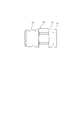
- FIG. 1 is an external view of a metal pipe joint according to the embodiment.
- the metal pipe joint 10 has a metal main body 12 and a release sleeve 13, and the metal main body 12 is formed with a threaded portion 11. Then, a tube is inserted on the release sleeve 13 side, and the screw portion 11 is attached to an external device.
- FIG. 2 is an external view of the resin pipe joint according to the embodiment.
- the resin pipe joint 20 includes a screw adapter 21, a resin main body 23, and a release sleeve 13.
- the screw adapter 21 is formed with a screw portion 22.
- a tube is inserted in the release sleeve 13 side, and the screw part 22 is attached to an external apparatus.
- the pipe joint of FIGS. 1 and 2 has a locking ring for holding a tube to be inserted.
- the threaded portions 11 and 22 are male threads and are tapered, and are pipe taper screws whose standards are unified by JIS. (According to JIS B0203 “Tapered screw for pipe”)
- a sealing material is applied to the threaded portions 11 and 22 or a sealing tape is wound around the threaded portions 11 and 22 in order to ensure sealing performance when fastened to the female screw of the external device.
- the manufacturer determines and manages the tightening torque and / or tightening method for each screw size. If the material of the threaded parts 11 and 22 of the metal pipe joint and the resin pipe joint is changed from brass to aluminum, even if the one specified for brass is applied or tightened with the tightening torque and / or tightening method, it will be galling or seized. May occur. In particular, galling and seizure are likely to occur in an aluminum material having a low tensile strength.
- the pipe joint used in the test had an external thread size of R1 / 4, and the tightening torque in the test was, for example, 14 N ⁇ m.
- the test was conducted by a method of visually confirming that there is no galling or seizure of the screw after repeating the fastening of the pipe joint to the female screw of Rc1 / 4 with the above torque three times.
- Example 1 of Table 1 a pipe joint made of aluminum and having a tensile strength of 560 (N / mm 2 ) or more was used.
- Example 2 a pipe joint made of aluminum and having a tensile strength of 375 (N / mm 2 ) or more was used.
- Comparative Example 1 a pipe joint made of aluminum and having a tensile strength of 310 (N / mm 2 ) or more was used.
- Comparative Example 2 a pipe joint made of brass and having a tensile strength of 335 (N / mm 2 ) or more was used.
- the tube connection part consists of a nut, a tightening part, and a parallel male screw formed on the main body. Even if this pipe joint is used, the present invention can be implemented as long as the material of the external thread to be fastened to the external device is the same as that of the embodiment. Various other forms can be implemented, and various omissions, replacements, and changes can be made without departing from the scope of the invention. These embodiments and modifications thereof are included in the scope and gist of the invention, and are included in the invention described in the claims and the equivalents thereof.
Landscapes
- Engineering & Computer Science (AREA)
- General Engineering & Computer Science (AREA)
- Mechanical Engineering (AREA)
- Non-Disconnectible Joints And Screw-Threaded Joints (AREA)
- Mutual Connection Of Rods And Tubes (AREA)
Abstract
一般空圧用途やその他の流体用途に使用されている管継手は、一般に黄銅材質である。近年、軽量で安価なアルミニウム材質の管継手を求められている。しかし、アルミ材質の管継手は外部機器に締結するための雄ねじを締結する際にかじりや焼き付きが生じやすい。そこで、アルミニウム材質の管継手の雄ねじを外部機器に形成された雌ねじに締結する際に、かじりや焼き付きが生じない安価な管継手を提供する。前記雄ねじ部が引張強度375(N/mm2)以上のアルミニウム材質である事を特徴とする。
Description
本発明の実施形態は、一般空気圧用途やその他の流体用途に使用できる配管用の管継手に関するものである。
管継手は、一端を外部機器に接続し、他端に配管を接続する管継手が開示されている(例えば、特許文献1)。上記特許文献1に記載の管継手の一端には、雄ねじが形成されており、外部機器に形成された雌ねじに締結される。このように構成された管継手は、一般に黄銅で形成されているが、近年、軽量で材料費が安価であるアルミニウムの管継手が所望されている。
しかしながら、アルミニウムで形成された管継手は、外部機器に形成された雌ねじに締結する際、雄ねじにかじりや焼き付きが生じやすい。
そこで本発明が解決しようとする課題は、雄ねじにかじりや焼き付きが生じないアルミニウム製の管継手を提供することを目的とする。
上記目的を達成するために、実施形態の管継手は、一端にチューブ接続部を1つ以上有し、他端に外部機器に接続するための雄ねじを有する管継手であって、前記雄ねじの材質が引張強度375(N/mm2)以上のアルミニウムである事を特徴とする。
実施形態の管継手によれば、外部機器に形成された雌ねじに締結する際にかじりや焼き付きが生じない安価な管継手を提供することができる。
以下、図面を参照して本発明の実施形態について説明する。
管継手には、本体とねじ部材が一体加工された金属材質の管継手(以下、金属管継手と称す。)と、本体の材質が樹脂で雄ねじの部材が金属材質で別部品の管継手(以下、樹脂管継手と称す。)がある。 図1は、実施形態に係る金属管継手の外観図である。
管継手には、本体とねじ部材が一体加工された金属材質の管継手(以下、金属管継手と称す。)と、本体の材質が樹脂で雄ねじの部材が金属材質で別部品の管継手(以下、樹脂管継手と称す。)がある。 図1は、実施形態に係る金属管継手の外観図である。
金属管継手10は、金属本体12とリリーススリーブ13を有しており、金属本体12は、ねじ部11が形成される。そして、リリーススリーブ13側にチューブを挿入し、ねじ部11を外部機器に取り付ける。
図2は、実施形態に係る樹脂管継手の外観図である。樹脂管継手20は、ねじアダプタ21、樹脂本体23、リリーススリーブ13を有する。ねじアダプタ21は、ねじ部22が形成される。そして、リリーススリーブ13側にチューブを挿入し、ねじ部22を外部機器に取り付ける。
図示していないが、図1、図2の管継手は、挿入されるチューブを保持する係止リングを有している。ねじ部11及び22は、雄ねじでテーパ形状であり、JISで規格が統一されている管用テーパねじである。(JIS B0203「管用テーパねじ」による。)
また、図示していないが、ねじ部11及び22には、外部機器の雌ねじに締結した際のシール性を確保するため、シール材を塗布するか、シールテープが巻かれる。
管継手を外部機器に締結する際は、メーカーがねじのサイズごとに締め付けトルク及び/又は締め付け方法を定めて管理している。金属管継手、樹脂管継手のねじ部11、22の材質を黄銅からアルミニウムに変更すると、黄銅用に定めたものを適用しても、締め付けトルク及び/又は締め付け方法で締結してもかじりや焼き付きが生じる場合がある。特に、引張強度が小さいアルミニウム材料ではかじりや焼き付きが生じやすい。
(締め付け試験)
管継手を締結する際にかじりや焼き付きが生じないアルミニウム材料を選定するため、引張強度(JIS Z2241「金属材料引張試験方法」による。)の異なる材料を加工した金属管継手で締め付け試験を行い、ねじのかじりや焼き付きの有無を比較して確認した。
管継手を締結する際にかじりや焼き付きが生じないアルミニウム材料を選定するため、引張強度(JIS Z2241「金属材料引張試験方法」による。)の異なる材料を加工した金属管継手で締め付け試験を行い、ねじのかじりや焼き付きの有無を比較して確認した。
試験に使用した管継手は、雄ねじサイズをR1/4とし、試験での締め付けトルクは、例えば14N・mとした。試験は、管継手をRc1/4の雌ねじに前記トルクで締結する事を3回繰り返した後、ねじのかじりや焼き付きがないか目視にて確認する方法で行った。
下表1は、その試験結果である。表1の実施例1では、材質がアルミニウムで、引張強度が560(N/mm2)以上の材料の管継手を使用した。また、実施例2では、材質がアルミニウムで、引張強度が375(N/mm2)以上の材料の管継手を使用した。一方、比較例1では、材質がアルミニウムで、引張強度が310(N/mm2)以上の材料の管継手を使用した。また、比較例2では、材質が黄銅で、引張強度が335(N/mm2)以上の材料の管継手を使用した。

表1の試験結果から、材質がアルミニウムで、引張強度が375(N/mm2)以上の材料の管継手では、かじりや焼き付きが生じない事が確認された。管継手にアルミニウム材質を選定する場合において、引張強度が560(N/mm2)以上の高価な高強度材料を使う必要はなく、引張強度が375(N/mm2)以上の材料であれば、ねじの締結でかじりや焼き付きが生じない事が確認できた。
本実施形態における管継手は、継手本体にチューブを挿入して係止リングにより係止する実施形態を説明したが、これらの実施形態は例として提示したものであり、発明の範囲を限定することは意図していない。
チューブ接続部がナットと締め付け部品と本体に形成された平行雄ねじよりなり、樹脂チューブを締め付け部品で変形させて取り付ける機構の管継手や、チューブ接続部が竹の子形状でチューブを拡径して取り付ける機構の管継手であっても、外部機器に締結する雄ねじ材質が実施例と同じであれば本発明が実施可能である。その他の様々な形態でも実施されることが可能であり、発明の要旨を逸脱しない範囲で、種々の省略、置き換え、変更を行うことができる。これら実施形態やその変形は、発明の範囲や要旨に含まれるとともに、特許請求の範囲に記載された発明とその均等の範囲に含まれる。
10 金属管継手
11 ねじ部
12 金属本体
13 リリーススリーブ
20 樹脂管継手
21 ねじアダプタ
22 ねじ部
23 樹脂本体
11 ねじ部
12 金属本体
13 リリーススリーブ
20 樹脂管継手
21 ねじアダプタ
22 ねじ部
23 樹脂本体
Claims (1)
- 一端にチューブ接続部を1つ以上有し、他端に外部機器に接続するための雄ねじを有する管継手であって、
前記雄ねじの材質が引張強度375(N/mm2)以上のアルミニウムである事を特徴とする管継手。
Priority Applications (1)
| Application Number | Priority Date | Filing Date | Title |
|---|---|---|---|
| JP2016510136A JPWO2015146406A1 (ja) | 2014-03-24 | 2015-02-23 | 管継手 |
Applications Claiming Priority (2)
| Application Number | Priority Date | Filing Date | Title |
|---|---|---|---|
| JP2014059865 | 2014-03-24 | ||
| JP2014-059865 | 2014-03-24 |
Publications (1)
| Publication Number | Publication Date |
|---|---|
| WO2015146406A1 true WO2015146406A1 (ja) | 2015-10-01 |
Family
ID=54194941
Family Applications (1)
| Application Number | Title | Priority Date | Filing Date |
|---|---|---|---|
| PCT/JP2015/054917 Ceased WO2015146406A1 (ja) | 2014-03-24 | 2015-02-23 | 管継手 |
Country Status (3)
| Country | Link |
|---|---|
| JP (1) | JPWO2015146406A1 (ja) |
| TW (1) | TW201540998A (ja) |
| WO (1) | WO2015146406A1 (ja) |
Citations (3)
| Publication number | Priority date | Publication date | Assignee | Title |
|---|---|---|---|---|
| JPS6199790A (ja) * | 1984-10-19 | 1986-05-17 | 富士精工株式会社 | オ−ルメタル超高真空継手 |
| JPH05196192A (ja) * | 1991-11-01 | 1993-08-06 | Nippondenso Co Ltd | プラグ |
| JPH11172359A (ja) * | 1997-12-12 | 1999-06-29 | Furukawa Electric Co Ltd:The | 高強度アルミニウム合金製ねじおよびその製造方法 |
-
2015
- 2015-02-16 TW TW104105301A patent/TW201540998A/zh unknown
- 2015-02-23 WO PCT/JP2015/054917 patent/WO2015146406A1/ja not_active Ceased
- 2015-02-23 JP JP2016510136A patent/JPWO2015146406A1/ja not_active Withdrawn
Patent Citations (3)
| Publication number | Priority date | Publication date | Assignee | Title |
|---|---|---|---|---|
| JPS6199790A (ja) * | 1984-10-19 | 1986-05-17 | 富士精工株式会社 | オ−ルメタル超高真空継手 |
| JPH05196192A (ja) * | 1991-11-01 | 1993-08-06 | Nippondenso Co Ltd | プラグ |
| JPH11172359A (ja) * | 1997-12-12 | 1999-06-29 | Furukawa Electric Co Ltd:The | 高強度アルミニウム合金製ねじおよびその製造方法 |
Also Published As
| Publication number | Publication date |
|---|---|
| TW201540998A (zh) | 2015-11-01 |
| JPWO2015146406A1 (ja) | 2017-04-13 |
Similar Documents
| Publication | Publication Date | Title |
|---|---|---|
| US9822912B2 (en) | Push-to-connect fitting device, arrangement and method | |
| US10291009B2 (en) | Integrated piping conduit with adaptor device and method | |
| MY191070A (en) | Threaded connection | |
| EA033015B1 (ru) | Резьбовое соединение для стальных труб | |
| US10096981B2 (en) | Integrated piping conduit with adaptor device and method | |
| EP3305986A3 (en) | Barrier cable coupler | |
| US2333350A (en) | Hose coupling | |
| SA520412111B1 (ar) | وصلة ملولبة لمواسير فولاذية | |
| CN104930280A (zh) | 异形夹 | |
| JP2009144916A (ja) | チューブとチューブ継手との接続方法及びそのチューブ継手 | |
| US10323777B2 (en) | Pipe coupling fitting with internal spacer sleeve | |
| US10871247B2 (en) | Compression couplings | |
| CN107482545B (zh) | 超级适配的管道本体 | |
| JP2015086979A (ja) | ホース継手用スリーブ、ホース継手及びホース継手構造体 | |
| KR100728174B1 (ko) | 관체 클램프기구 | |
| WO2015146406A1 (ja) | 管継手 | |
| JP3195332U (ja) | 継手構造 | |
| WO2015151584A1 (ja) | 狭所配管用継手 | |
| CN107304859A (zh) | Pvc排水管用管卡 | |
| JP2015197195A5 (ja) | ||
| JP5689916B2 (ja) | 管継手 | |
| US20150240973A1 (en) | Spigot couplings | |
| CN204677926U (zh) | 一种接头 | |
| JP2014003789A (ja) | 防爆形ケーブルグランドのケーブルクランプ装置 | |
| SI2202439T1 (sl) | Navojna prikljuäśna objemka za pritrjevanje podolgovatih predmetov ali cevi |
Legal Events
| Date | Code | Title | Description |
|---|---|---|---|
| 121 | Ep: the epo has been informed by wipo that ep was designated in this application |
Ref document number: 15767739 Country of ref document: EP Kind code of ref document: A1 |
|
| ENP | Entry into the national phase |
Ref document number: 2016510136 Country of ref document: JP Kind code of ref document: A |
|
| NENP | Non-entry into the national phase |
Ref country code: DE |
|
| 122 | Ep: pct application non-entry in european phase |
Ref document number: 15767739 Country of ref document: EP Kind code of ref document: A1 |