WO2015145774A1 - スピーカシステム - Google Patents
スピーカシステム Download PDFInfo
- Publication number
- WO2015145774A1 WO2015145774A1 PCT/JP2014/059362 JP2014059362W WO2015145774A1 WO 2015145774 A1 WO2015145774 A1 WO 2015145774A1 JP 2014059362 W JP2014059362 W JP 2014059362W WO 2015145774 A1 WO2015145774 A1 WO 2015145774A1
- Authority
- WO
- WIPO (PCT)
- Prior art keywords
- duct
- opening
- speaker
- inlet
- cabinet
- Prior art date
- Legal status (The legal status is an assumption and is not a legal conclusion. Google has not performed a legal analysis and makes no representation as to the accuracy of the status listed.)
- Ceased
Links
Images




Classifications
-
- H—ELECTRICITY
- H04—ELECTRIC COMMUNICATION TECHNIQUE
- H04R—LOUDSPEAKERS, MICROPHONES, GRAMOPHONE PICK-UPS OR LIKE ACOUSTIC ELECTROMECHANICAL TRANSDUCERS; ELECTRIC HEARING AIDS; PUBLIC ADDRESS SYSTEMS
- H04R1/00—Details of transducers, loudspeakers or microphones
- H04R1/02—Casings; Cabinets ; Supports therefor; Mountings therein
- H04R1/025—Arrangements for fixing loudspeaker transducers, e.g. in a box, furniture
-
- H—ELECTRICITY
- H04—ELECTRIC COMMUNICATION TECHNIQUE
- H04R—LOUDSPEAKERS, MICROPHONES, GRAMOPHONE PICK-UPS OR LIKE ACOUSTIC ELECTROMECHANICAL TRANSDUCERS; ELECTRIC HEARING AIDS; PUBLIC ADDRESS SYSTEMS
- H04R1/00—Details of transducers, loudspeakers or microphones
- H04R1/20—Arrangements for obtaining desired frequency or directional characteristics
- H04R1/22—Arrangements for obtaining desired frequency or directional characteristics for obtaining desired frequency characteristic only
- H04R1/28—Transducer mountings or enclosures modified by provision of mechanical or acoustic impedances, e.g. resonator, damping means
- H04R1/2807—Enclosures comprising vibrating or resonating arrangements
- H04R1/2815—Enclosures comprising vibrating or resonating arrangements of the bass reflex type
- H04R1/2823—Vents, i.e. ports, e.g. shape thereof or tuning thereof with damping material
- H04R1/2826—Vents, i.e. ports, e.g. shape thereof or tuning thereof with damping material for loudspeaker transducers
-
- H—ELECTRICITY
- H04—ELECTRIC COMMUNICATION TECHNIQUE
- H04R—LOUDSPEAKERS, MICROPHONES, GRAMOPHONE PICK-UPS OR LIKE ACOUSTIC ELECTROMECHANICAL TRANSDUCERS; ELECTRIC HEARING AIDS; PUBLIC ADDRESS SYSTEMS
- H04R1/00—Details of transducers, loudspeakers or microphones
- H04R1/20—Arrangements for obtaining desired frequency or directional characteristics
- H04R1/22—Arrangements for obtaining desired frequency or directional characteristics for obtaining desired frequency characteristic only
- H04R1/28—Transducer mountings or enclosures modified by provision of mechanical or acoustic impedances, e.g. resonator, damping means
- H04R1/2869—Reduction of undesired resonances, i.e. standing waves within enclosure, or of undesired vibrations, i.e. of the enclosure itself
- H04R1/2873—Reduction of undesired resonances, i.e. standing waves within enclosure, or of undesired vibrations, i.e. of the enclosure itself for loudspeaker transducers
-
- H—ELECTRICITY
- H04—ELECTRIC COMMUNICATION TECHNIQUE
- H04R—LOUDSPEAKERS, MICROPHONES, GRAMOPHONE PICK-UPS OR LIKE ACOUSTIC ELECTROMECHANICAL TRANSDUCERS; ELECTRIC HEARING AIDS; PUBLIC ADDRESS SYSTEMS
- H04R1/00—Details of transducers, loudspeakers or microphones
- H04R1/20—Arrangements for obtaining desired frequency or directional characteristics
- H04R1/32—Arrangements for obtaining desired frequency or directional characteristics for obtaining desired directional characteristic only
- H04R1/34—Arrangements for obtaining desired frequency or directional characteristics for obtaining desired directional characteristic only by using a single transducer with sound reflecting, diffracting, directing or guiding means
- H04R1/345—Arrangements for obtaining desired frequency or directional characteristics for obtaining desired directional characteristic only by using a single transducer with sound reflecting, diffracting, directing or guiding means for loudspeakers
-
- H—ELECTRICITY
- H04—ELECTRIC COMMUNICATION TECHNIQUE
- H04R—LOUDSPEAKERS, MICROPHONES, GRAMOPHONE PICK-UPS OR LIKE ACOUSTIC ELECTROMECHANICAL TRANSDUCERS; ELECTRIC HEARING AIDS; PUBLIC ADDRESS SYSTEMS
- H04R1/00—Details of transducers, loudspeakers or microphones
- H04R1/20—Arrangements for obtaining desired frequency or directional characteristics
- H04R1/22—Arrangements for obtaining desired frequency or directional characteristics for obtaining desired frequency characteristic only
- H04R1/28—Transducer mountings or enclosures modified by provision of mechanical or acoustic impedances, e.g. resonator, damping means
- H04R1/2807—Enclosures comprising vibrating or resonating arrangements
- H04R1/2853—Enclosures comprising vibrating or resonating arrangements using an acoustic labyrinth or a transmission line
- H04R1/2857—Enclosures comprising vibrating or resonating arrangements using an acoustic labyrinth or a transmission line for loudspeaker transducers
Definitions
- the present invention relates to a speaker system.
- a speaker cabinet described in Patent Document 1 is known as the above-described speaker system.
- the speaker cabinet includes a first cabinet to which a speaker unit is attached, and a second cabinet that forms a bass reflex duct attached to the bottom surface of the first cabinet.
- An opening communicating with the bass reflex duct is provided at an end of the first cabinet bottom wall.
- the first cabinet is provided in a substantially rectangular parallelepiped shape and has three pairs of wall portions facing each other. Between the wall portions facing each other, standing waves each having a node as a node and an antinode as a center are generated. In general, the amplitude of the standing wave is minimum at the vibration node, but the sound pressure is maximum at the vibration node. As described above, when an opening is provided at the end of the first cabinet bottom wall, an opening is provided in a portion corresponding to a node of the standing wave, that is, a portion where the sound pressure of the standing wave is maximized. For this reason, there has been a problem that the influence of standing waves on the sound radiated through the bass reflex duct becomes large. In particular, if an opening is provided in the bottom wall of the first cabinet that is vertically long, a large peak or dip occurs at a low frequency.
- an object of the present invention is to provide a speaker system that is not easily affected by standing waves.
- the invention described in claim 1 is a speaker device, a speaker mounting wall to which the speaker device is mounted, an opposing wall facing the speaker mounting wall, the speaker mounting wall, and the A cabinet having two pairs of opposite side walls provided between the opposing walls, and a first duct communicating with the inside of the cabinet is provided on the side wall of the cabinet, and the cabinet and the first
- the speaker system is characterized in that a first opening communicating with an inlet of one duct is provided at a position including one center of the pair of side walls having a small distance between the two pairs of side walls.
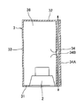
- FIG. 3 is a sectional view taken along line II-II in FIG. 2.
- FIG. 4 is a sectional view taken along line III-III in FIG. 3. It is explanatory drawing for demonstrating the standing wave which arises in the speaker system shown in FIG. It is a graph which shows the frequency characteristic of the speaker system shown in FIG. 1, and the 1st duct provided in this speaker system.
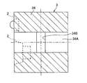
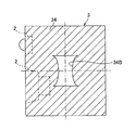
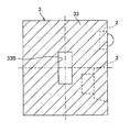
- It is the II sectional view taken on the line of FIG. 2 in another Example.
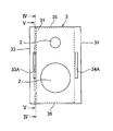
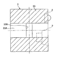
- It is a front view of the speaker system of the present invention in the second embodiment. It is the IV-IV sectional view taken on the line of FIG. It is the VV sectional view taken on the line of FIG.
- a speaker system includes a speaker device, a speaker mounting wall to which the speaker device is mounted, a facing wall facing the speaker mounting wall, and facing each other provided between the speaker mounting wall and the facing wall.
- the first opening can be provided in the portion corresponding to the antinode of the low-frequency standing wave that easily affects the frequency characteristics of the speaker, that is, the portion where the sound pressure of the standing wave is minimized. Less affected.
- the first duct may be extended along the side wall provided with the first opening, and the outlet of the first duct may be provided closer to the sound emission direction side of the speaker device than the inlet. Thereby, the sound which passed the 1st duct can be radiated
- the first duct may be extended along the side wall provided with the first opening, and the outlet of the first duct may be provided on the opposite side of the sound emission direction of the speaker device from the inlet. Thereby, the sound which passed the 1st duct can be radiated
- a second duct that communicates with the interior of the cabinet is provided on the side wall of the cabinet, and the second opening that communicates the interior of the cabinet with the second duct inlet is formed at the center of the other of the pair of side walls with a small distance from each other. You may be provided in the position to include. As a result, the second opening can be provided in the portion corresponding to the antinode of the low-frequency standing wave that easily affects the frequency characteristics of the speaker, that is, the portion where the sound pressure of the standing wave is minimized. Less affected.
- At least one of the first duct or the second duct extends along the side wall provided with the first opening or the second opening communicated with the inlet, and at least one of the first duct or the second duct is provided.
- the outlet may be provided closer to the sound emission direction of the speaker device than the inlet.
- At least one of the first duct or the second duct extends along the side wall provided with the first opening or the second opening communicated with the inlet, and at least one of the first duct or the second duct is provided.
- the outlet may be provided on the opposite side of the sound emission direction of the speaker device from the inlet.
- the first duct may be provided so that the area increases as it goes from the entrance to the exit. Thereby, sound can be radiated without generating unnecessary turbulence in the air in the first duct.
- the width of the first duct in the direction parallel to the side wall provided with the first opening increases from the inlet toward the outlet, and the width in the direction orthogonal to the side wall provided with the first opening becomes constant. It may be provided as follows. Thereby, the area of a 1st duct can be enlarged as it goes to an exit, maintaining the width
- At least one of the first duct or the two ducts may be provided so that the area increases as it goes from the entrance to the exit. Thereby, a sound can be radiated without generating unnecessary turbulent flow or the like in the air in the first duct or the second duct.
- At least one of the first duct and the second duct has a width in the direction parallel to the side wall provided with the first opening or the second opening as it goes from the inlet to the outlet, and the first opening or the second opening. It may be provided so that the width in the direction orthogonal to the side wall provided with is constant. Accordingly, the area of the second duct can be increased from the entrance toward the exit while keeping the width in the direction orthogonal to the side wall provided with the second opening of the speaker system constant.
- entrance of the said 1st duct in a 1st opening may be provided so that it may become near as it approaches the center. Thereby, a sound can be radiated without generating unnecessary turbulent flow or the like in the air in the first duct.
- the edge portion facing in the direction from the inlet to the outlet of the first duct or the second duct that communicates with the first opening is provided so as to become closer to the center. It may be done. Thereby, a sound can be radiated without generating unnecessary turbulent flow or the like in the air in the first duct or the second duct.
- the speaker system 1 includes a speaker device 2 and a rectangular parallelepiped cabinet 3 to which the speaker device 2 is attached.
- two speaker devices 2 are attached to the cabinet 3.
- the cabinet 3 is provided between a front wall 31 as a speaker mounting wall to which the speaker device 2 is mounted, a rear wall 32 as an opposing wall facing the front wall 31, and between the front wall 31 and the rear wall 32.
- a pair of side walls 33 and 34 and side walls 35 and 36 are provided.
- the two speaker devices 2 are mounted side by side on the inner surface of the front wall 31.
- the front wall 31 is provided in a rectangular shape in which the arrangement direction of the two speaker devices 2 is long.
- the rear wall 32 is provided in a long rectangular shape.
- the arrangement direction will be described as the vertical direction
- the facing direction of the front wall 31 and the rear wall 32 will be the front-rear direction
- the direction orthogonal to both the arrangement direction and the front-rear direction will be described as the left-right direction.
- Each of the side walls 33 to 36 stands from the edge of the front wall 31 toward the edge of the rear wall 32.
- the side walls 33 and 34 are erected from the edge of the front wall 31 along the vertical direction, and face each other in the left-right direction.
- These side walls 33 and 34 are provided with substantially the same shape and the same area.
- the side walls 35 and 36 are erected from an edge portion along the left-right direction of the front wall 31 and face each other in the vertical direction.
- These side walls 35 and 36 are also provided with substantially the same shape and the same area.
- the distance between the side walls 33 and 34 is smaller than the distance between the side walls 35 and 36. That is, the side walls 33 and 34 are a pair of side walls having a small distance from each other among the two pairs of the side walls 33 and 34 and the side walls 35 and 36.
- a first duct 34A that communicates with the inside of the cabinet 3, which is a space surrounded by the walls 31 to 36, is provided on the side wall 34 that is one of the pair of side walls 33 and 34. .
- the first duct 34 ⁇ / b> A allows the bass generated from the rear side in the front-rear direction of the speaker device 2 to pass through the cabinet 3 and radiate it outside the cabinet 3.
- the cross section of the first duct 34A is provided in a rectangular shape that is long in the vertical direction, and is provided so as to have a certain area from the inlet to the outlet.
- the side wall 34 is provided with a first opening 34B that connects the inside of the cabinet 3 and the inlet of the first duct 34A at a position including the center.
- the first opening 34 ⁇ / b> B is provided in a rectangular shape that is long in the vertical direction.
- the vertical height of the first opening 34B is the same as the vertical height of the first duct 34A.
- the bass emitted from the rear side of the speaker device 2 enters the first duct 34A from the first opening 34B as shown in FIG.
- the light passes through 34 ⁇ / b> A and is radiated out of the cabinet 3 through openings provided in the front wall 31 and the rear wall 32.
- the standing wave generated inside the cabinet 3 will be described with reference to FIG.
- a phenomenon called resonance or resonance occurs by creating two walls (edges) perpendicular to the traveling direction in a one-dimensional wave or plane wave. In the portion sandwiched between the two ends, the wave reflected at one end is reflected again at the other end. By repeating this process, a standing wave having a highly amplified amplitude is generated.
- the standing wave W1 is a standing wave in which the side wall 35 and the side wall 36, which are fixed ends, become nodes, and the center between the side wall 35 and the side wall 36 becomes an antinode.
- the standing wave W2 is a standing wave in which the front wall 31 and the rear wall 32 which are fixed ends are nodes, and the center between the front wall 31 and the rear wall 32 is an antinode.
- the standing wave W3 is a standing wave in which the side wall 33 and the side wall 34, which are fixed ends, become nodes, and the center between the side wall 33 and the side wall 34 becomes an antinode.
- the distance between the side walls 35 and 36 is the longest, then the distance between the front wall 31 and the rear wall 32 is long, and the distance between the side walls 33 and 34 is the shortest. Accordingly, the standing waves W1 to W3 have the lowest frequency of the standing wave W1, the next lower the standing wave W2, and the highest the standing wave W3.
- L1 indicates the frequency characteristic of the first duct 34A
- L2 indicates the frequency characteristic of the entire speaker system 1.
- the first duct 34A is a duct through which a low sound is guided. For this reason, the frequency characteristic of the first duct 34A has a high sound pressure at a low frequency and low at a high frequency.
- the frequency characteristics of the first duct 34A are disturbed at the frequencies of the respective standing waves W1 to W3, and the influence thereof affects the frequency characteristics of the speaker system 1. That is, if there are no standing waves W1 to W3, the frequency characteristics of the first duct 34A should gradually decrease as the frequency becomes higher as indicated by L1 in the figure, but the influence of the standing waves W1 to W3 will be reduced. As a result, the frequency characteristics are disturbed as indicated by N11 to N13.
- N11, N12, and N13 represent disturbances in the frequency characteristics of the first duct 34A due to the influence of the standing waves W1, W2, and W3, respectively.
- the sound pressure of the first duct 34A is high, and thus the frequency characteristics of the speaker system 1 are likely to be affected.
- the sound pressure of the first duct 34A is not so high, so that the frequency characteristic of the speaker system 1 is hardly affected.
- the frequency characteristic of the speaker system 1 is flat in the high frequency region as indicated by L2 in the figure, but is affected by the standing waves W1 and W2, and N21, N22 As shown in FIG. 3, the frequency characteristics are disturbed.
- N21 and N22 indicate disturbances in the frequency characteristics of the speaker system 1 due to the influence of the standing waves W1 and W2, respectively. However, there is almost no disturbance in the frequency characteristics due to the influence of the standing wave W3.
- the first opening 34B is provided at a position including the center of the side wall 34 which is one of the side walls 33 and 34 having a small distance from each other.
- the first opening 34B is located at the portion corresponding to the antinodes of the low standing waves W1 and W2 that easily affect the frequency characteristics of the speaker system 1, that is, the standing waves W1 and W2.
- the first opening 34B is provided in a portion corresponding to the node of the standing wave W3, that is, a portion where the sound pressure of the standing wave W3 is maximized, but as described above, the first wave 34B of the standing wave W3 having a high frequency is provided. The impact is small.
- the first duct 34A has the same area at any position from the inlet to the outlet, and the first opening 34B is provided in a rectangular shape, but the present invention is not limited to this.
- the first duct 34A may be provided in a horn shape whose area increases from the inlet toward the outlet. Thereby, sound can be radiated without generating unnecessary turbulence or the like in the air in the first duct 34A.
- the vicinity of the inlet of the first duct 34A may be provided in a shape such that the area decreases toward the outlet and then increases toward the outlet.
- the area of the first duct 34A can be increased from the entrance toward the exit while keeping the width in the left-right direction of the speaker system 1 constant.
- the first duct 34A may be provided in a horn shape, and the first opening 34B may be rectangular like the first embodiment.
- the second duct 33A allows the bass generated from the rear side in the front-rear direction of the speaker device 2 to pass through the cabinet 3 and radiate it outside the cabinet 3.
- the second duct 33A also extends in the front-rear direction along the side wall 33, and the outlets thereof are provided on the front and rear sides of the second duct 33A inlet. That is, the front wall 31 and the rear wall 32 are respectively provided with openings serving as outlets of the second duct 33A.
- the cross section of the second duct 33A is provided in a rectangular shape that is long in the vertical direction, and is provided so as to have a certain area from the inlet to the outlet.
- the side wall 33 is provided with a second opening 33B that communicates the inside of the cabinet 3 with the inlet of the second duct 33A at a position including the center.
- the second opening 33B is provided in a rectangular shape that is long in the vertical direction. The vertical height of the second opening 33B is the same as the vertical height of the second duct 33A.
- the second opening 33B at a position including the center of the side wall 33, the portion corresponding to the antinodes of the standing waves W1 and W2 having a low frequency is guided to the second duct 33A.
- the influence of W1 to W3 can be reduced.
- the second duct 33A may be provided so that the area increases from the entrance to the exit. Further, the second duct 33A may be provided such that the width in the vertical direction becomes wider as it goes from the inlet to the outlet, and the width in the left and right direction becomes constant from the inlet to the outlet. Similarly to the first opening 34B shown in FIGS. 8 and 9, the second opening 33B also has an edge that faces in the direction from the inlet of the second duct 33A toward the outlet in the second opening 33B as it approaches the center. You may provide so that it may become close.
- outlets of the first duct 34A and the second duct 33A are provided at two locations on the front side and the rear side, but the present invention is not limited to this.
- the outlets of the first duct 34A and the second duct 33A may be provided on either the front side or the rear side.
- the cabinet 3 is provided in a rectangular parallelepiped shape, but is not limited to this.
- the cabinet 3 should just be a substantially rectangular parallelepiped shape, for example, the shape which the corner
- the two speaker devices 2 are attached to the cabinet 3, but the present invention is not limited to this. Only one speaker device 2 may be attached to the cabinet 3 or three or more speaker devices 2 may be attached.
Landscapes
- Health & Medical Sciences (AREA)
- Otolaryngology (AREA)
- Physics & Mathematics (AREA)
- Engineering & Computer Science (AREA)
- Acoustics & Sound (AREA)
- Signal Processing (AREA)
- Details Of Audible-Bandwidth Transducers (AREA)
- Obtaining Desirable Characteristics In Audible-Bandwidth Transducers (AREA)
Abstract
Description
次に、第1実施例におけるスピーカシステムについて図1~図6を参照して説明する。同図に示すように、スピーカシステム1は、スピーカ装置2と、このスピーカ装置2が取り付けられる直方体状のキャビネット3と、を備えている。本実施例において、キャビネット3には、2台のスピーカ装置2が取り付けられている。上記キャビネット3は、スピーカ装置2が取り付けられるスピーカ取付壁としての前壁31と、この前壁31に対向する対向壁としての後壁32と、前壁31及び後壁32間に設けられた2対の側壁33及び34、側壁35及び36と、を有している。
次に、第2実施例におけるスピーカシステム1について図10~図12を参照して説明する。第1実施例と第2実施例とで異なる点は、互いの距離が小さい一対の側壁33及び34の他方である側壁33に第2ダクト33A及び第2開口33Bが設けられている点である。
2 スピーカ装置
3 キャビネット
31 前壁(スピーカ取付壁)
32 後壁(対向壁)
33~36 側壁
33A 第2ダクト
33B 第2開口
34A 第1ダクト
34B 第1開口
Claims (12)
- スピーカ装置と、
前記スピーカ装置が取り付けられるスピーカ取付壁と、該スピーカ取付壁に対向する対向壁と、前記スピーカ取付壁及び前記対向壁間に設けられた互いに対向する2対の側壁と、を有するキャビネットと、を備え、
前記キャビネットの側壁には、当該キャビネット内部と連通する第1ダクトが設けられ、
前記キャビネット内部と前記第1ダクト入口とを連通する第1開口が、前記2対の側壁のうち互いの距離が小さい一対の側壁の一方の中央を含む位置に設けられた
ことを特徴とするスピーカシステム。 - 前記第1ダクトが、前記第1開口が設けられた側壁に沿って延在され、
前記第1ダクトの出口が、入口よりも前記スピーカ装置の音放射方向側に設けられた
ことを特徴とする請求項1に記載のスピーカシステム。 - 前記第1ダクトが、前記第1開口が設けられた側壁に沿って延在され、
前記第1ダクトの出口が、入口よりも前記スピーカ装置の音放射方向と反対側に設けられた
ことを特徴とする請求項1に記載のスピーカシステム。 - 前記キャビネットの側壁には、当該キャビネット内部と連通する第2ダクトが設けられ、
前記キャビネット内部と前記第2ダクト入口とを連通する第2開口が、前記互いの距離が小さい一対の側壁の他方の中央を含む位置に設けられた
ことを特徴とする請求項1に記載のスピーカシステム。 - 前記第1ダクト又は前記第2ダクトの少なくとも一方が、その入口に連通された前記第1開口又は前記第2開口が設けられた側壁に沿って延在され、
前記第1ダクト又は前記第2ダクトの少なくとも一方の出口が、入口よりも前記スピーカ装置の音放射方向側に設けられた
ことを特徴とする請求項4に記載のスピーカシステム。 - 前記第1ダクト又は前記第2ダクトの少なくとも一方が、その入口に連通された前記第1開口又は前記第2開口が設けられた側壁に沿って延在され、
前記第1ダクト又は前記第2ダクトの少なくとも一方の出口が、入口よりも前記スピーカ装置の音放射方向と反対側に設けられた
ことを特徴とする請求項4に記載のスピーカシステム。 - 前記第1ダクトは、入口から出口に向かうに従って面積が広くなるように設けられた
ことを特徴とする請求項1に記載のスピーカシステム。 - 前記第1ダクトは、入口から出口に向かうに従って前記第1開口が設けられた側壁と平行方向の幅が広くなり、かつ、前記第1開口が設けられた側壁と直交する方向の幅が一定となるように設けられた
ことを特徴とする請求項7に記載のスピーカシステム。 - 前記第1ダクト又は前記2ダクトの少なくとも一方が、入口から出口に向かうに従って面積が広くなるように設けられた
ことを特徴とする請求項4に記載のスピーカシステム。 - 前記第1ダクト又は前記第2ダクトの少なくとも一方が、入口から出口に向かうに従って前記第1開口又は前記第2開口が設けられた側壁と平行方向の幅が広くなり、かつ、前記第1開口又は前記第2開口が設けられた側壁と直交する方向の幅が一定となるように設けられた
ことを特徴とする請求項9に記載のスピーカシステム。 - 前記第1開口において前記第1ダクトの入口から出口に向かう方向に対向する縁部が、中央に近づくに従って近くなるように設けられた
ことを特徴とする請求項1に記載のスピーカシステム。 - 前記第1開口又は前記2開口の何れか一方において、当該一方が連通する前記第1ダクト又は前記第2ダクトの入口から出口に向かう方向に対向する縁部が、中央に近づくに従って近くなるように設けられた
ことを特徴とする請求項4に記載のスピーカシステム。
Priority Applications (3)
| Application Number | Priority Date | Filing Date | Title |
|---|---|---|---|
| US15/129,082 US9854339B2 (en) | 2014-03-28 | 2014-03-28 | Speaker system |
| PCT/JP2014/059362 WO2015145774A1 (ja) | 2014-03-28 | 2014-03-28 | スピーカシステム |
| JP2016509864A JP6243513B2 (ja) | 2014-03-28 | 2014-03-28 | スピーカシステム |
Applications Claiming Priority (1)
| Application Number | Priority Date | Filing Date | Title |
|---|---|---|---|
| PCT/JP2014/059362 WO2015145774A1 (ja) | 2014-03-28 | 2014-03-28 | スピーカシステム |
Publications (1)
| Publication Number | Publication Date |
|---|---|
| WO2015145774A1 true WO2015145774A1 (ja) | 2015-10-01 |
Family
ID=54194358
Family Applications (1)
| Application Number | Title | Priority Date | Filing Date |
|---|---|---|---|
| PCT/JP2014/059362 Ceased WO2015145774A1 (ja) | 2014-03-28 | 2014-03-28 | スピーカシステム |
Country Status (3)
| Country | Link |
|---|---|
| US (1) | US9854339B2 (ja) |
| JP (1) | JP6243513B2 (ja) |
| WO (1) | WO2015145774A1 (ja) |
Cited By (1)
| Publication number | Priority date | Publication date | Assignee | Title |
|---|---|---|---|---|
| WO2025022701A1 (ja) * | 2023-07-25 | 2025-01-30 | パナソニックIpマネジメント株式会社 | スピーカ装置 |
Families Citing this family (2)
| Publication number | Priority date | Publication date | Assignee | Title |
|---|---|---|---|---|
| KR102533426B1 (ko) | 2018-05-03 | 2023-05-17 | 삼성전자 주식회사 | 전자장치의 관로 구조 및 이를 포함하는 전자장치 |
| US11330364B1 (en) * | 2021-01-12 | 2022-05-10 | Robert Bosch Gmbh | Ported speaker assembly |
Citations (5)
| Publication number | Priority date | Publication date | Assignee | Title |
|---|---|---|---|---|
| JPH04126488U (ja) * | 1991-05-09 | 1992-11-18 | オンキヨー株式会社 | スピーカボツクス |
| JPH0638284A (ja) * | 1992-07-14 | 1994-02-10 | Pioneer Electron Corp | 位相反転式スピーカ装置 |
| JPH0662484A (ja) * | 1992-08-05 | 1994-03-04 | Mitsubishi Electric Corp | バスレフ方式スピーカーシステム |
| JP2000295682A (ja) * | 1999-04-06 | 2000-10-20 | Pioneer Electronic Corp | 音響筐体及び吸音パネル |
| US6654472B1 (en) * | 1999-06-26 | 2003-11-25 | Lg Electronics Inc. | Speaker system in display |
Family Cites Families (10)
| Publication number | Priority date | Publication date | Assignee | Title |
|---|---|---|---|---|
| WO1991019406A1 (fr) * | 1990-05-25 | 1991-12-12 | Mitsubishi Denki Kabushiki Kaisha | Structure de haut-parleur |
| JPH04126488A (ja) | 1990-09-18 | 1992-04-27 | Canon Inc | ディジタル信号処理装置 |
| US5757946A (en) * | 1996-09-23 | 1998-05-26 | Northern Telecom Limited | Magnetic fluid loudspeaker assembly with ported enclosure |
| JP3763682B2 (ja) * | 1998-10-14 | 2006-04-05 | パイオニア株式会社 | スピーカ装置 |
| US6912390B2 (en) * | 2000-12-22 | 2005-06-28 | Telefonaktiebolaget Lm Ericsson | Connection handling in SRNC relocation |
| US7162049B2 (en) * | 2003-01-07 | 2007-01-09 | Britannia Investment Corporation | Ported loudspeaker system and method with reduced air turbulence, bipolar radiation pattern and novel appearance |
| US7207413B2 (en) * | 2003-06-02 | 2007-04-24 | Tbi Audio Systems Llc | Closed loop embedded audio transmission line technology for loudspeaker enclosures and systems |
| US7181039B2 (en) * | 2004-01-30 | 2007-02-20 | Step Technologies Inc. | Thermal chimney equipped audio speaker cabinet |
| EP1816273A1 (en) * | 2006-02-01 | 2007-08-08 | FEI Company | Enclosure for acoustic insulation of an apparatus contained within said enclosure |
| JP6044164B2 (ja) * | 2011-09-09 | 2016-12-14 | ヤマハ株式会社 | 音響装置 |
-
2014
- 2014-03-28 JP JP2016509864A patent/JP6243513B2/ja active Active
- 2014-03-28 WO PCT/JP2014/059362 patent/WO2015145774A1/ja not_active Ceased
- 2014-03-28 US US15/129,082 patent/US9854339B2/en active Active
Patent Citations (5)
| Publication number | Priority date | Publication date | Assignee | Title |
|---|---|---|---|---|
| JPH04126488U (ja) * | 1991-05-09 | 1992-11-18 | オンキヨー株式会社 | スピーカボツクス |
| JPH0638284A (ja) * | 1992-07-14 | 1994-02-10 | Pioneer Electron Corp | 位相反転式スピーカ装置 |
| JPH0662484A (ja) * | 1992-08-05 | 1994-03-04 | Mitsubishi Electric Corp | バスレフ方式スピーカーシステム |
| JP2000295682A (ja) * | 1999-04-06 | 2000-10-20 | Pioneer Electronic Corp | 音響筐体及び吸音パネル |
| US6654472B1 (en) * | 1999-06-26 | 2003-11-25 | Lg Electronics Inc. | Speaker system in display |
Cited By (1)
| Publication number | Priority date | Publication date | Assignee | Title |
|---|---|---|---|---|
| WO2025022701A1 (ja) * | 2023-07-25 | 2025-01-30 | パナソニックIpマネジメント株式会社 | スピーカ装置 |
Also Published As
| Publication number | Publication date |
|---|---|
| US20170127164A1 (en) | 2017-05-04 |
| JPWO2015145774A1 (ja) | 2017-04-13 |
| US9854339B2 (en) | 2017-12-26 |
| JP6243513B2 (ja) | 2017-12-06 |
Similar Documents
| Publication | Publication Date | Title |
|---|---|---|
| JP6255400B2 (ja) | 凹状ポートを有する、バスレフ型スピーカ | |
| US20160353199A1 (en) | Omni-directional ported speaker | |
| US10200784B2 (en) | Speaker box structure of electronic device | |
| JP7699607B2 (ja) | 音響装置 | |
| JP6243513B2 (ja) | スピーカシステム | |
| US20140291065A1 (en) | Loudspeaker having external extension | |
| JP7774663B2 (ja) | スピーカシステム | |
| US11206479B2 (en) | Speaker device and speaker cabinet | |
| EP2568718B1 (en) | Audio apparatus | |
| US9049517B2 (en) | Transmission line loudspeaker | |
| CN108781315B (zh) | 具有不同模块壳体几何形状和相似声学特性的扬声器模块 | |
| US9473848B2 (en) | Transmission line loudspeaker | |
| US20120288129A1 (en) | Open-back woofer baffle with resonance control ports | |
| US8807268B2 (en) | Loudspeaker | |
| JP6665613B2 (ja) | スピーカ装置 | |
| JP6880170B2 (ja) | スピーカシステム | |
| ITRM20120622A1 (it) | Diffusore acustico | |
| HK1188891B (zh) | 扬声器 | |
| JP2010068063A (ja) | スピーカーボックス |
Legal Events
| Date | Code | Title | Description |
|---|---|---|---|
| 121 | Ep: the epo has been informed by wipo that ep was designated in this application |
Ref document number: 14886696 Country of ref document: EP Kind code of ref document: A1 |
|
| ENP | Entry into the national phase |
Ref document number: 2016509864 Country of ref document: JP Kind code of ref document: A |
|
| WWE | Wipo information: entry into national phase |
Ref document number: 15129082 Country of ref document: US |
|
| NENP | Non-entry into the national phase |
Ref country code: DE |
|
| 122 | Ep: pct application non-entry in european phase |
Ref document number: 14886696 Country of ref document: EP Kind code of ref document: A1 |