WO2015145708A1 - Wireless communication system and control device - Google Patents
Wireless communication system and control device Download PDFInfo
- Publication number
- WO2015145708A1 WO2015145708A1 PCT/JP2014/059068 JP2014059068W WO2015145708A1 WO 2015145708 A1 WO2015145708 A1 WO 2015145708A1 JP 2014059068 W JP2014059068 W JP 2014059068W WO 2015145708 A1 WO2015145708 A1 WO 2015145708A1
- Authority
- WO
- WIPO (PCT)
- Prior art keywords
- terminal
- wireless
- data
- performance level
- communication
- Prior art date
Links
- 238000004891 communication Methods 0.000 title claims abstract description 190
- 230000005540 biological transmission Effects 0.000 claims abstract description 41
- 238000000034 method Methods 0.000 claims description 32
- 238000012546 transfer Methods 0.000 claims description 13
- 238000012545 processing Methods 0.000 description 35
- 230000006870 function Effects 0.000 description 22
- 230000014759 maintenance of location Effects 0.000 description 15
- 238000012790 confirmation Methods 0.000 description 11
- 230000008054 signal transmission Effects 0.000 description 9
- 238000010586 diagram Methods 0.000 description 6
- 230000007274 generation of a signal involved in cell-cell signaling Effects 0.000 description 4
- 238000006243 chemical reaction Methods 0.000 description 2
- 230000010365 information processing Effects 0.000 description 2
- 238000005259 measurement Methods 0.000 description 2
- 238000012986 modification Methods 0.000 description 2
- 230000004048 modification Effects 0.000 description 2
- 239000000470 constituent Substances 0.000 description 1
- 230000000694 effects Effects 0.000 description 1
- 238000005516 engineering process Methods 0.000 description 1
- 230000000717 retained effect Effects 0.000 description 1
Images


Classifications
-
- H—ELECTRICITY
- H04—ELECTRIC COMMUNICATION TECHNIQUE
- H04W—WIRELESS COMMUNICATION NETWORKS
- H04W36/00—Hand-off or reselection arrangements
- H04W36/24—Reselection being triggered by specific parameters
- H04W36/32—Reselection being triggered by specific parameters by location or mobility data, e.g. speed data
- H04W36/322—Reselection being triggered by specific parameters by location or mobility data, e.g. speed data by location data
-
- H—ELECTRICITY
- H04—ELECTRIC COMMUNICATION TECHNIQUE
- H04W—WIRELESS COMMUNICATION NETWORKS
- H04W36/00—Hand-off or reselection arrangements
- H04W36/24—Reselection being triggered by specific parameters
- H04W36/32—Reselection being triggered by specific parameters by location or mobility data, e.g. speed data
- H04W36/324—Reselection being triggered by specific parameters by location or mobility data, e.g. speed data by mobility data, e.g. speed data
-
- H—ELECTRICITY
- H04—ELECTRIC COMMUNICATION TECHNIQUE
- H04W—WIRELESS COMMUNICATION NETWORKS
- H04W28/00—Network traffic management; Network resource management
- H04W28/02—Traffic management, e.g. flow control or congestion control
- H04W28/06—Optimizing the usage of the radio link, e.g. header compression, information sizing, discarding information
-
- H—ELECTRICITY
- H04—ELECTRIC COMMUNICATION TECHNIQUE
- H04W—WIRELESS COMMUNICATION NETWORKS
- H04W72/00—Local resource management
- H04W72/12—Wireless traffic scheduling
Definitions
- the present invention relates to a radio communication technique in a radio communication system including at least a terminal, a radio station, and a gateway.
- Patent Document 1 discloses a method for controlling a communication session. Specifically, for a service that does not require real-time performance, data communication from start to end is divided into one or more communication sessions. The base station statistically collects the mobile station position and transmission power information, and stores the transmission power information as a database for each route from the map information. Then, the base station controls the communication session so that the communication session is performed where there is little propagation loss of radio waves and large transmission power is not required.
- Patent Document 1 describes a method for controlling a communication session when the propagation environment is poor, but only assumes a situation in which a mobile station communicates with one base station. For this reason, there is no description of what control is performed when the propagation environment is bad in a situation where the mobile station performs handover and communicates with a plurality of base stations.
- the present invention is a wireless communication apparatus that can perform communication between a radio station and a terminal in a good communication state when the terminal performs communication with a plurality of base stations while performing handover.
- An object is to provide a communication system, method and apparatus.
- a wireless communication system including a plurality of wireless stations that perform wireless communication with a terminal, a gateway connected to the plurality of wireless stations, and a control device connected to at least the plurality of wireless stations.
- a map creation unit that creates in advance a map indicating the relationship between the movement path of the terminal and information indicating the communication performance level between the terminal and the radio station;
- a scheduling unit that schedules data transmission to a terminal of a radio station, and a determination that determines whether or not the terminal exists at a position where the communication performance level is lower than a threshold when transmitting data to the terminal based on the map and scheduling
- a data holding unit that holds data and a plurality of wireless stations at a position where the communication performance level is higher than the threshold when it is determined that the terminal exists at a position where the communication performance level is lower than the threshold.
- a wireless station that is a connection destination of the terminal to be controlled has a control unit that controls to transmit the stored data.
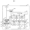
- FIG. 1 is a diagram illustrating a configuration of a wireless communication system according to the first embodiment.
- the wireless communication system includes at least a gateway (11), a wireless station 1 (12), a wireless station 2 (14), and a control device for the wireless communication system. (16) and a terminal (17).
- the communication areas of the wireless station 1 (12) and the wireless station 2 are illustrated as a communication area 1 (13) and a communication area 2 (15), respectively. This indicates that the terminal moves from the communication area (13) of the wireless station 1 (12) to the communication area (15) of the wireless station 2 (14).
- the gateway (11) is connected to a server (19) such as a Web content server via the Internet (18).
- data from the server (19) to the terminal (17) is transmitted to the wireless station (12) or the wireless station 2 (14) via the gateway (11), and the wireless station performs wireless communication. Send data to the terminal.
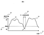
- the control device (16) is a map that shows the state of the communication performance level (22) with each wireless station with respect to the position (21) on the moving path of the terminal as shown in FIG. Create This map is created by collecting information on the communication performance level for several locations on the route, and interpolating using the information for the location where the information was collected for locations where information is not collected. The result is held in the map holding unit of the control device. The method for creating this map will be described later.
- the left curve (23) shows the state of the communication performance level when communicating with the wireless station 1
- the right curve (24) shows the state of the communication performance level when communicating with the wireless station 2.
- the control device sets a data holding section (25) that is not suitable for communication between the terminal and the wireless station in the map.
- the data holding section (25) is, for example, a section in which the communication performance level is lower than the threshold (26) preset in the communication performance level.
- the threshold (26) is set by the system operator.
- information on the position of the map is converted into information on time (162) as shown in FIG. 3 by estimating the average moving speed of the terminal.
- the time that the terminal is estimated to be in a location corresponding to the data holding section is defined as the data holding time (163), and the data addressed to the terminal sent from the server is held in the wireless station or gateway during the data holding time. Control to do.
- control is performed so that the data addressed to the terminal is transmitted from the handover destination radio station.
- the control device (16) also performs control of data retention in the gateway or the radio station.
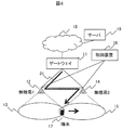
- FIG. 4 shows a data flow (31) from the gateway (11) to the terminal (17) when the data to the terminal is held by the wireless station in the wireless system of the present embodiment.
- the gateway (11) transmits the data addressed to the terminal (17) sent from the server to the wireless station 1 (12) currently transmitting to the terminal.
- the control device performs radio station transmission scheduling.
- the control device (16) Instructs the terminal to hold the data. If the terminal is handed over to the wireless station 2 while the wireless station 1 holds the data, the data addressed to the terminal is transferred to the wireless station 2 (14) to the wireless station 1 (12). Instruct to transfer. Then, the control device (16) performs control so that the wireless station 2 transmits data to the terminal after the end of the data holding time. By performing such control, it is possible to prevent data from being transmitted when the communication performance level between the radio station and the terminal is low, and to transmit data with a high communication performance level.
- the probability of transmission failure can be reduced, and as a result, radio resources can be effectively utilized.
- the control device does not wait for the handover of the terminal.
- data may be transmitted from the wireless station 1 to the wireless station 2 and the data addressed to the terminal may be retained until the data retention time ends at the wireless station 2.
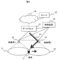
- FIG. 5 shows a data flow (41) in the case where the data addressed to the terminal is held not by the base station 1 (12) but by the gateway (11).
- the control device is also connected to the gateway.
- the gateway notifies the control device that it has received data for the terminal.
- the control device Upon receiving the notification, the control device performs transmission scheduling of the radio station to which the terminal is connected.
- the control device when it is determined that the time for transmitting data from the wireless station to the terminal is a time after the start time of the data holding time, the control device (16) sends the data to the terminal to the gateway (11). Instruct to retain the data.
- the gateway is controlled so that the data addressed to the terminal is transmitted to the wireless station after the handover.
- the control device does not wait for the handover of the terminal.
- the data may be transmitted from the gateway to the wireless station 2 to the terminal.
- Whether the data to the terminal is held by the wireless station or the gateway may be determined by the operator of the wireless system according to the application.
- the data to the terminal (17) is not directly passed through the wireless station (12) currently communicating with the terminal, but directly from the gateway (11), after the handover. 2 (14), the data transfer to the terminal handed over between the radio stations does not occur. Therefore, communication resources can be used efficiently.
- the map shown in FIG. 2 shows the relationship between the position of the terminal and the communication performance level between the terminal and the radio station.
- the communication performance level between the terminal and the radio station is, for example, the magnitude of the received power of the signal from the base station measured by the terminal, the CQI (Channel Quality Indicator) that is an indicator indicating the quality information of the downlink channel,
- the state of wireless communication between the terminal and the wireless station is represented by information such as the number of retransmission requests from the terminal.
- the communication performance level for example, the value of received power, CQI, or the number of retransmission requests may be converted into a numerical value.
- the result of comprehensively determining the state of wireless communication from the values for the two indices of received power and CQI is digitized, and the result of estimating the state of wireless communication using the numerical value is expressed as a communication performance level. Also good. What is necessary is just to comprise so that the magnitude
- the terminal is configured to transmit information related to the state of wireless communication and also feed back information related to the position of the terminal to the wireless station.
- Information on the position of the terminal can be obtained, for example, by utilizing GPS (Global Positioning System) or detecting the position using the principle of triangulation using a plurality of radio stations.
- GPS Global Positioning System
- the control device receives information on the communication performance level and position from the radio station, stores it in the memory in the control device, and creates the map shown in FIG. 2 using the statistical information.
- control device may be configured so as to hold error information with respect to the average value therein.
- the map may be created by measuring the communication performance level multiple times at a predetermined position prior to system operation.
- information may be collected by associating the communication performance level with the location information by using the GPS described above, and a map may be created using the statistical information.
- the present invention is particularly excellent in application to an environment in which a plurality of terminals are moving at a similar speed in a certain direction.
- a suitable example is the movement of terminals on a highway.
- a plurality of vehicles are moving at a speed within a certain range on a predetermined movement route. Therefore, the terminal moving with the vehicle can be regarded as moving along a route determined at a speed within a certain range. It is apparent that this embodiment can be applied to environments other than highways as long as a plurality of terminals can be regarded as moving at a similar speed in a certain direction.
- the terminal is configured to periodically feed back information on the communication performance level with the radio station, and the radio station obtains the information from the time when the information fed back from the terminal is received. What is necessary is just to comprise so that calculated time may be calculated. Or you may comprise so that a terminal may feed back together the information regarding a communication performance level, and the information regarding the time when the information was acquired.
- the control device receives the above information from the radio station and stores it in a memory in the control device.
- the control device is required to have a function for converting information relating to time into information relating to position, which will be described below.
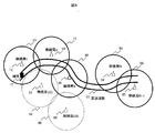
- a plurality of radio stations are arranged around the highway (61) that is the movement route of the terminal (17), and each radio station has a communication area (13, 15) as shown in FIG. , 52, 54, 56, 58, 60) will be described.
- a terminal (17) moving on the highway from the left side to the right side in FIG. 6 travels on the highway (61), and wirelessly transmits from the wireless station 1 (12) to the wireless station 2 (14). It is estimated that a handover is performed from the station 2 (14) to the radio station 3 (51) and from the radio station N (53) to the radio station N + 1 (55). Therefore, it is determined that the terminal that has handed over the radio stations in this order is moving from the left side to the right side in FIG.
- a terminal moving on the highway from the right side to the left side in FIG. 6 travels on the highway, so that the radio station N + 1 is transferred from the radio station N to the radio station N, the radio station 3 is transferred to the radio station 2, and the wireless station 2 is The terminal that is estimated to be handed over to the station 1 and handed over the radio stations in this order is determined to be moving from the right side to the left side of the road.
- handover is performed from the wireless station 1 (12) to the wireless station 101 (57) and from the wireless station 101 (57) to the wireless station 102 (59), Can be considered.
- the terminal location and moving speed are estimated using the history of handover of the terminal.
- FIG. 7 is a conceptual diagram showing a point where a handover is estimated to occur and a distance of a moving route of the terminal between the points.
- a handover occurrence point is measured a plurality of times in advance, and a position serving as an average point is calculated from the statistical information as a handover estimation point.
- the distance of the expressway between the handover estimated points is measured in advance, and this information is held in the control device.
- handover estimation in which a handover from the wireless station 2 to the wireless station 3 is estimated to occur from a handover estimated point 1 (71) where a handover from the wireless station 1 to the wireless station 2 is estimated to occur. It shows that the distance (74) to the point 2 (72) is AAAm.
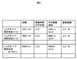
- FIG. 8 is an example of a table in which the control apparatus collects and summarizes information about when the terminal has performed handover from which radio station to which radio station.
- each wireless station notifies the control device of information related to handover.
- the terminal 1 is configured to notify the control device of the time when the terminal 1 performs handover from the wireless station 1 to the wireless station 2.
- the terminal 1 is configured to notify the control device of the time at which the terminal 1 is handed over from the wireless station 2 to the wireless station 3.
- the radio station notifies the control apparatus of the time.
- FIG. 8 Similar information is collected for other terminals traveling on the highway, for example, terminal 2 and terminal N, and the table shown in FIG. 8 is created.
- a handover from the wireless station 1 to the wireless station 2 occurs at 10: 5: 8
- a handover from the wireless station 2 to the wireless station 3 occurs at 10:05:44.
- the control device creates the table shown in FIG. 9 based on the information in FIG. 7 and the information in FIG.
- FIG. 9 is a diagram illustrating an example of a table summarizing the estimation results of the average moving speed and error range of the terminal obtained from the distance between the handover estimated points and the average value of the moving time between the handover estimated points in the first embodiment. It is.
- the table shown in FIG. 9 is created by the following method. From the information shown in FIG. 7, for example, it can be seen that the distance between the handover estimated point 1 and the handover estimated point 2 is AAAm.
- the average value of the time required for the terminal to move from the handover estimated point 1 to the handover estimated point 2 can be obtained from the information on the occurrence time of handover of the plurality of terminals described in the table shown in FIG. it can.
- the average travel time from the handover estimated point 1 to the handover estimated point 2 is a leap second.
- the average moving speed between the handover estimated point 1 and the handover estimated point 2 can be estimated as AAA / a [m / sec].
- the error range for the average moving speed can also be calculated based on the error information for the average calculated from the measurements of FIGS.
- the control device uses the time when the communication performance level information was acquired as the position information. Convert. Specifically, the time until the time when the communication performance level information is acquired is calculated based on the time when the terminal handover occurs. By multiplying the time by the average moving speed, the distance from the handover occurrence point is calculated, and the position of the terminal is estimated. Then, the map shown in FIG. 2 is created by associating the communication performance level information with the position information. Thus, the map shown in FIG. 2 can be created without using GPS or measuring the communication performance level at a predetermined position.
- a map showing the communication performance level with respect to the relative time from the handover occurrence time can be created by using the average moving speed of the terminal and setting it based on the time when the handover occurred.
- the terminals moving on the expressway are moving at almost the same speed within a certain time range. Therefore, using the map information created in the past shown in FIG. 2 and FIG. 3, the position or time when the communication performance level falls below the threshold, and the position or time for recovering the state are estimated. Specifically, scheduling of the radio station is performed, and the transmission time of data to the terminal is obtained. Next, using the data transmission time to the terminal and the map shown in FIG. 3, it is determined whether or not the data transmission time to the terminal corresponds to the data holding time. Estimate time above threshold. In addition, the difference between the data transmission time and the current time is multiplied by the average moving speed to estimate the distance that the terminal moves by the time of data transmission.
- the position of the terminal at the time of data transmission is estimated.
- the control device wirelessly transmits the data to the terminal at a time when the communication performance level exceeds the threshold or when the terminal exists at a position where the communication performance level exceeds the threshold. Instructs the station or gateway to hold the data to the terminal.
- the average moving speed of the terminal is calculated based on the position and time estimated to cause handover of the radio station, but the average moving speed of the terminal may be obtained using other methods.
- the average speed may be obtained by using information related to traffic such as traffic jam information, or by using a speed limit on a highway when there is no traffic jam.
- control device performs control so that the wireless station holds data.
- description will be given focusing on one terminal, but the wireless station may communicate with a plurality of terminals.
- the terminal 1 periodically notifies the currently connected wireless station 1 of the communication performance level (1300).
- the wireless station notifies the control device of information relating to the communication performance level and the time when the information was acquired as communication performance related information (1301).
- the radio station notifies the control apparatus of information related to the handover of the terminal (1301).
- the control device collects communication performance related information and handover related information from each wireless station (1302).
- the control device uses this information to create and update a map related to the communication performance level and time (1303).
- the wireless station 1 notifies the control device that the data to the terminal 1 has been received (1305).
- the control device estimates the current position of terminal 1 and the average moving speed (1306).
- the current position can be estimated in the same manner as described above using the handover occurrence time, the current time, and the average moving speed.
- the control apparatus performs scheduling of the wireless station 1 to which the terminal 1 is connected (1307), and determines that the transmission of the data to the terminal 1 is after the start time of the data holding time (1308).
- the wireless station 1 is instructed to hold data in the terminal 1 (1309).
- the radio station 2 notifies the control device of the handover of the terminal 1 (1310).
- the control device receives this notification and performs scheduling of the wireless station 2 (1311), and calculates a standby time for transmitting data to the terminal 1 after the end of the data holding time (1312).
- the control device instructs the wireless station 1 to transfer the data of the terminal 1 to the wireless station 2 and a waiting time until the transfer (1313).
- the wireless station 1 transfers the data of 1 to the terminal to the wireless station 2 after the end of the waiting time (1314).
- the wireless station 2 transmits the transferred data to the terminal 1 to the terminal 1 (1315).
- a function that equalizes the absolute time between the control device and the radio station may be implemented, and the time management may be performed using the time, and the time may be set between the control device and the radio station. It is also possible to configure such that the time management is performed at the relative time by providing the reference.
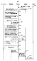
- FIG. 10 shows a sequence when it is determined that the transmission of the data to the terminal 1 is after the start time of the data holding time.
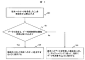
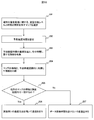
- FIG. 11 shows an operation flowchart of the control device for the determination. . In FIG. 11, operations overlapping with those in FIG. 10 are omitted.
- the control apparatus is notified from the wireless station that data for the terminal has been received from the gateway (141).
- the control device determines whether the data transmission is after the start time of the data holding time (142).
- the determination result is Yes, the wireless station is instructed to hold data to the terminal (143), and when the determination result is No, the wireless station that has received the data from the gateway to the terminal is controlled.
- the terminal is instructed to transmit data according to the scheduling determined by the apparatus (144).
- control device performs control so that data is held in the gateway.
- description will be given focusing on one terminal, but the wireless station may communicate with a plurality of terminals.
- the gateway receives data for the terminal 1, the gateway notifies the control device of the reception (2104). Upon receiving this notification, the control device estimates the current position of terminal 1 and the average moving speed (2105). Next, the control apparatus performs scheduling of the radio station 1 to which the terminal 1 is connected (2016), and when it is determined that the transmission of the data to the terminal 1 is after the start time of the data holding time (2107) The gateway is instructed to hold data in the terminal 1 (2108), and the gateway stores the data in the memory (2109). When the terminal is handed over to the radio station 2, the radio station 2 notifies the control device of the handover of the terminal 1 (2110).
- the control apparatus Upon receiving this notification, the control apparatus performs scheduling of the radio station 2 (2111), calculates a standby time for transmitting data to the terminal 1 after the data holding time ends from the created map, and waits (2112). ).
- the control device instructs the gateway to transmit the data to the terminal 1 to the wireless station 2 after the end of the standby time (2113).
- the gateway updates the forwarding table (2114), and transmits the data of terminal 1 to wireless station 2 (2115).
- the radio station 2 transmits data to the terminal 1 according to the scheduling of the control device (2116).
- FIG. 12 shows a sequence when it is determined that the transmission of the data to the terminal 1 is after the start time of the data holding time.
- the operation flow of the control apparatus for the determination is the same except that the notification target is changed from a wireless station to a gateway in FIG.
- the terminal 91 includes at least a wireless signal transmission / reception unit 92 that transmits and receives wireless signals, a wireless communication control unit 93 that controls wireless communication between the wireless station and the terminal, and an application control unit 94 that controls terminal applications. It is configured.
- the wireless signal transmission / reception unit 92, the wireless communication control unit 93, and the application control unit 94 are connected by a bus 95, and can exchange signals with each other.
- the wireless signal transmission / reception unit 92 transmits / receives a wireless signal to / from the wireless station.
- the wireless communication control unit 93 includes a feedback information creating unit 96 that creates feedback information to the wireless station.
- the feedback information creation unit 96 includes a CQI information creation unit 97 that creates Channel Quality Indicator (CQI) information to be fed back to the radio station, and a received power information creation unit 98 that creates information about the magnitude of received power. Is done.
- CQI Channel Quality Indicator
- the wireless station (100) controls a wired interface (103) serving as an interface to other devices connected to the wireless station by wire, a wireless signal transmission / reception unit (101) that performs wireless communication with the terminal, and the operation of the wireless station. And a bus (104) for connecting each functional block in the radio station. Included in the conversion of a signal received via the wired interface (103) into a wireless signal, in a wireless station, for example, conversion of a signal created by the wireless station operation control unit into a wireless signal, and a wireless signal transmission / reception unit The radio signal received by the antenna is converted into a digital signal by the radio signal transmitting / receiving unit (101).
- the radio station operation control unit (102) that controls the operation of the radio station includes a signal processing unit (105) that processes a signal that the radio station communicates with other devices, and the signal processing unit (105)
- a transmission signal processing unit (1015) that performs processing, a reception signal processing unit (1019) that processes received signals, and a control signal processing unit (106) that processes control signals are configured.
- the notification signal processing unit (107) includes a communication performance related information collecting unit (108) that collects information on the magnitude of received power and channel quality indicator (CQI) information included in the signal received by the wireless station from the terminal, A handover management unit (109) for managing the handover of the terminal, a signal generation and transmission processing unit (1017) for generating a signal for notifying the control device of the communication performance related information and the information related to the handover, and a transmission processing unit (1017) Consists of CQI) information included in the signal received by the wireless station from the terminal.
- a handover management unit (109) for managing the handover of the terminal
- a signal generation and transmission processing unit (1017) for generating a signal for notifying the control device of the communication performance related information and the information related to the handover
- the communication performance related information collection unit (108) has a function of calculating the measured time of the communication performance from the time when the wireless station receives the information related to the communication performance fed back from the terminal.
- the handover manager (109) manages the occurrence of terminal handover including the time.
- a signal for notifying the control device of information related to the handover of the terminal is generated by the signal generation and transmission processing unit (1017) together with information regarding the time at which the control is performed, and transmitted to the control device.
- the data retention related information processing unit (1010) is a data reception notification processing unit 10 (1018) that performs processing for notifying the control device that data has been received by the terminal, and control that processes a signal transmitted from the control device.
- Each processing unit may be configured to hold an internal memory, or may be configured to temporarily store data to be transmitted to a terminal or a handover destination of the terminal in the memory.
- processing unit which is a feature of the present invention, it may be configured to have a function equivalent to that of a general wireless station.
- the scheduling function for determining the schedule for transmitting data to the terminal is configured not to be installed in the radio station but to be provided in the control device. What is necessary is just to comprise so that data may be transmitted according to the instruction
- the control device by giving the control device a scheduling function, it is possible to perform scheduling in consideration of communication states of a plurality of radio stations managed by the control device.
- the radio station can simplify the function.
- scheduling is not performed only by the control device, but each wireless station is also equipped with a scheduling function, which is more sophisticated for data transmission to terminals whose communication performance level is higher than a threshold.
- the scheduling function may be distributed and implemented between the control device and the radio station, such as when scheduling is performed within the radio station.
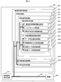
- the main function of the control device of the present embodiment is to understand the communication performance level in the wireless communication between the wireless station and the terminal in the movement path of the terminal, and a map representing the communication performance level with respect to the position as shown in FIG. Is to create. Further, a position that is lower than the threshold of the communication performance level preset by the system operator for the map is determined as a data holding section. Further, by estimating the average moving speed of the terminal and converting the communication performance level with respect to the terminal position to the communication performance level with respect to time based on the estimation result of the average moving speed, the data holding time is determined. is there.
- the control device After performing the above, as described with reference to FIGS. 10 to 12, the control device performs scheduling of the radio station to which the terminal is connected, and as a result, the data transmission time is the start time of the data holding time. If it is determined that it will be thereafter, the wireless station or gateway is instructed to hold data in the terminal. Then, control is performed so that data is transmitted from the wireless station to the terminal outside the data holding time. Therefore, the control device (110) includes a data control unit (111) that performs the above control, an interface (IF) (1118), and a bus (1119). Below, the data control part (111) especially relevant to a present Example is demonstrated.
- the data control unit includes a map management unit (115) that manages maps, a data retention control unit (1112) that controls data retention, and, as shown in FIG. 10 or FIG. It comprises a signal transmission / reception processing unit (1117) for processing a signal for performing communication with the gateway.
- the map management unit (115) includes a communication performance related information collection unit (116) that collects communication performance related information transmitted from a wireless station, and information on the location of the terminal, for example, GPS, in order to estimate the location of the terminal , Information related to handover, location history information collection unit (117) that collects information such as the history of handover and the time required to move between handover estimated points, and processes the signal that notifies the handover of the terminal notified from the radio station
- a map creation and update processing unit (1110) for appropriately performing update processing and a map holding unit (1111) for holding the created map are configured. It is.
- the data holding control unit (1112) includes a scheduling unit (1113) that performs scheduling of the radio station, a data holding determination unit (1114) that determines whether to hold the data, and the data holding control unit (1114) illustrated in FIGS. It comprises a standby time calculation unit (1115) that calculates the standby time described in the operation sequence, and a control signal generation unit (1116) that generates a control signal to be transmitted to a wireless station or a gateway.
- FIG. 16 is a configuration diagram of a gateway used in a wireless system in which data to the terminal is held by the gateway.
- the gateway includes an interface (IF) (122, 123, 124, 125), a buffer (126), an internal header addition unit (127), a transfer table (128), a switching unit (129), a table management unit (1210), and data holding It is comprised from a control part (1211).
- interface # 0 (IF # 0) (122) is an interface with the control device
- interface # 1 (IF # 1) (123) is an interface with the Internet
- interface # 2 (IF # 2) (124) to interface #n (IF # n) (125) are interfaces with the radio station.
- Data sent from the server via the Internet is input to the data holding control unit (1211).
- a reception notification signal processing unit (1212) that generates and transmits a signal for notifying the control device that the data to the terminal has been received, and from the control device instructing data holding It comprises a control signal processing unit (1213) for processing signals and a memory (1214) for storing data instructed to be held.
- the input data is input to the buffer (126) to add an internal header.
- the internal header is added to the data by the internal header adding unit (127) for adding the internal header in accordance with the transfer table (128) storing the information indicating the transfer destination, and the switching is performed by the switching unit (129).
- the table management unit (1210) that manages the information of the transfer table receives the information from the control device.
- the signal transmitted from the control device and instructing the change of the data transmission destination to the terminal is processed by the control signal processing unit (1213) and transmitted to the table management unit.
- the data held in the memory (1214) in accordance with an instruction from the control device is input to the buffer (126) to which the internal header is added, and after the internal header is added, it is directed to a predetermined radio station. Switched to output.
- the bus may be configured by including a central processing unit (CPU) as a processing unit, a memory as a storage unit, and an input / output unit as necessary.
- CPU central processing unit
- a program for operation is stored in a memory or the like, and is executed by the CPU as necessary to realize the above-described functions.
- the first embodiment even when a terminal performs communication with a plurality of radio stations while performing handover, it can be controlled to perform communication in a state where the communication performance level between the terminal and the radio station is good. Therefore, the frequency utilization efficiency of the wireless communication system can be improved. Furthermore, in the present embodiment, even when there is no function for notifying position information from the terminal and speed information to the wireless station, a position where the communication performance level is improved for the terminal is predicted, and the wireless station and the terminal are It is possible to provide a wireless communication system, method, and apparatus capable of performing communication between each other.
- Example 2 of the present invention will be described.
- the wireless communication system according to the first embodiment is suitable for use in a wireless communication with an environment in which a plurality of terminals travel in the same direction at a substantially equal moving speed, for example, a terminal moving on a highway, etc., on a certain route.
- a substantially equal moving speed for example, a terminal moving on a highway, etc.
- a map of the communication performance level and the position or time created by the control device based on the information on the communication performance level fed back by the terminal that has already moved along the same movement route and the information collected by the wireless station regarding the handover of the terminal. It is considered that information can be applied to terminals having the same average moving speed.
- the above information can be updated while being created based on information for a certain period of time collected from terminals and radio stations.
- the average moving speed of the terminal is significantly different from the average moving speed of the past terminal, there may occur a case where the map of the relationship between the communication performance level currently used by the control device and the time cannot be applied.
- a radio communication system for dealing with such a situation will be described.
- FIG. 17 is a map showing the error range (194) in addition to the average value (193) of the communication performance level between the wireless station and the plurality of terminals.
- the second embodiment as shown in FIG. 17, at least a part of the time not corresponding to the data holding time (195) is set as the predicted confirmation time (196), and this time is used to move the route from now on. Is determined to be suitable for the map indicating the relationship between the communication performance level (191) and the time (192) obtained from the past terminal.
- the control device estimates the route from which the terminal will move from the information of the handover of the terminal in the memory of the control device, and shows the relationship between the communication performance level and time created in the past with respect to the route.
- a map is selected (201).
- a prediction confirmation time is set for the map (202).
- the prediction confirmation time in this embodiment can be determined by the system operator, but it is desirable that the prediction confirmation time is long. In the present embodiment, when all the times other than the data holding time are set as the predicted confirmation time, the predicted confirmation time can be set to the longest time.
- the communication performance fed back from the terminal and information related to the time are collected from the wireless station (203).
- the control device uses the time when the terminal is handed over to the radio station that is currently communicating as a reference, information on the map indicating the relationship between the selected communication performance level and time, and information collected within the predicted confirmation time for the terminal. Are compared (204). Next, it is determined whether the information of the terminal matches the existing map information within the error range (205). If the information matches within the error range, the terminal can apply the selected map. It is determined that there is, and it is determined to perform communication using the communication method described in the first embodiment (206). If the error is out of the error range, the terminal determines that the selected map cannot be applied, and decides to perform communication without providing a data holding time (207).
- the terminal when it is determined that they match within the error range, the terminal can be determined to be a terminal that is moving on the route at the same average moving speed as the terminal used for creating the map used for the determination.
- Information collected by communication between the terminal and the wireless station may be stored in a memory as one of the map data.
- the average moving speed of the terminal is considered to be different from the average moving speed of the terminal in the map showing the relationship between the selected communication performance level and time.
- a new map may be created based on the obtained information indicating the relationship between the communication performance level and time.
- a plurality of maps showing the relationship between the communication performance level and the time are prepared, and information collected within the predicted confirmation time for the terminal is an error range.
- the operation of comparing whether or not they match may be performed on a plurality of maps.
- the wireless communication system As in the second embodiment, it is possible to confirm the suitability of the terminal with respect to the map used for the determination of the data retention time. Therefore, the terminal that shows an operation different from the operation predicted by the control device However, it is possible to provide a radio communication system, method and apparatus suitable for the terminal.
- the present embodiment is characterized in that the transmission method of the radio station is changed when it is out of the error range and when the terminal stays in the data holding section exceeds a predetermined threshold.
- the control device operates according to the operation flowchart shown in FIG.
- the control device newly creates a map showing the relationship between the time (162) and the communication performance level (161) as shown in FIG. 3 based on the information obtained by the terminal determined to be out of the error range (171). ).
- the time during which the communication performance level is equal to or lower than the predetermined threshold, that is, the data holding time is calculated (172).
- the calculated data retention time is compared with a predetermined upper limit value (173). As a result of the comparison, it is determined whether the calculated data retention time is longer than a predetermined upper limit value (174). If it is long, an operation of changing the transmission method of the related radio station is performed (175), and if it is short, the transmission method of the radio station is not changed (176).
- Changing the transmission method of the radio station is, for example, changing the antenna to be used by preparing a plurality of antennas having different directivities, or changing the beam pattern using the array antenna technology, or Various known techniques such as changing the transmission power of a radio station or transmitting a signal by linking two adjacent radio stations are applicable. In the present embodiment, among them, it is preferable to use a technique for improving the communication performance of the edge portion of the communication area of the wireless station.
- the communication performance level of the portion corresponding to the edge of the communication area of two adjacent wireless stations can be improved by changing the transmission method of the wireless stations. For example, on a highway, it is possible to improve the communication performance level of a terminal in a vehicle that has been congested for a long time at a portion corresponding to the edge of the communication area. As a result, for example, as shown in FIG. 20, in the map showing the relationship between the communication performance level and the time, the data holding time (183) when the communication performance level is below the threshold can be shortened.
- the system operator determines the upper limit of the data retention time.
- the upper limit value of the data retention time is not limited to one, and may be configured to set a different value depending on the terminal. For example, in a terminal that can perform best effort communication, the upper limit of the data retention time is increased, and wireless communication is performed. For a terminal that guarantees a certain performance level, the upper limit of the data holding time may be set short. Also, different values may be set depending on the time zone during which communication is performed. Thus, it goes without saying that the upper limit of the data holding time may be variously changed according to the policy of the system operator.
- the wireless system may be configured to perform an operation of changing the transmission method of the related wireless station.
- the change in the transmission method of the wireless station is, for example, for some wireless resources such as changing only the wireless resource used for data transmission to the terminal where the upper limit of the data holding time is set short. Only the transmission method may be changed.
- the third embodiment of the present invention it can be prevented that the communication performance level between the terminal and the wireless station is in a bad state for a predetermined time or longer. Therefore, it is possible to provide a wireless communication system in which a wireless station and a terminal can communicate with each other with a good communication performance level within a certain period of time. Therefore, occurrence of timeout in communication can be reduced. According to such a system, for example, when a traffic jam occurs on an expressway, it is possible to avoid a situation in which the moving speed of the terminal is slow and a specific terminal is long in a state where the communication performance level is poor.
- the control device can be configured as one device separately from the radio station and the gateway. Further, the function of the control device may be incorporated inside any one of the radio stations, or the same function may be incorporated for each radio station, or the functions may be distributed among a plurality of radio stations. . Moreover, you may comprise so that the function of a control apparatus may be integrated in a gateway apparatus.
Abstract
The purpose of the present invention is to provide a wireless communication system with which, when a terminal communicates with a plurality of wireless stations while handing over, it is possible to perform communication between the wireless station and the terminal in a condition that the communication state is good. The communication system is controlled so as to hold data when determination is made during data transmission to the terminal as to whether the terminal exists at a position where the communication performance level is lower than a threshold and it is determined that the terminal exists at the position where the communication performance level is lower than the threshold, and to transmit data when the terminal exists at a position where the communication performance level is higher than the threshold.
Description
本発明は、少なくとも端末、無線局、ゲートウェイとから構成された無線通信システムにおける無線通信技術に関する。
The present invention relates to a radio communication technique in a radio communication system including at least a terminal, a radio station, and a gateway.
電波状態が悪い環境における基地局と移動局の通信を改善する技術の一例として、特許文献1には、通信セッションを制御する方法が開示されている。具体的には、リアルタイム性を必要としないサービスを対象として、データ通信の開始から終了までを1つまたは複数の通信セッションに分割する。基地局で移動局の位置及び送信電力情報を統計的に収集し、地図情報から路線ごとに送信電力情報をデータベースとして保持しておく。そして、基地局は、電波の伝搬損失が少なく、大きな送信電力を必要としないところで、通信セッションを行なうように通信セッションを制御する。
As an example of a technique for improving communication between a base station and a mobile station in an environment where the radio wave condition is bad, Patent Document 1 discloses a method for controlling a communication session. Specifically, for a service that does not require real-time performance, data communication from start to end is divided into one or more communication sessions. The base station statistically collects the mobile station position and transmission power information, and stores the transmission power information as a database for each route from the map information. Then, the base station controls the communication session so that the communication session is performed where there is little propagation loss of radio waves and large transmission power is not required.
特許文献1では、伝搬環境が悪い場合の通信セッションの制御方法について記載されているが、移動局が1の基地局と通信する状況しか想定していない。そのため、移動局がハンドオーバしながら、複数の基地局と通信する状況において、伝搬環境が悪い場合にどのような制御を行うかについては記載がされていない。
Patent Document 1 describes a method for controlling a communication session when the propagation environment is poor, but only assumes a situation in which a mobile station communicates with one base station. For this reason, there is no description of what control is performed when the propagation environment is bad in a situation where the mobile station performs handover and communicates with a plurality of base stations.
本発明はこのような事情を鑑み、端末がハンドオーバをしながら複数の基地局との通信を行なう場合において、通信状態がよい状態で無線局と端末との間での通信を行なうことができる無線通信システム、方法ならびに装置を提供することを目的とする。
In view of such circumstances, the present invention is a wireless communication apparatus that can perform communication between a radio station and a terminal in a good communication state when the terminal performs communication with a plurality of base stations while performing handover. An object is to provide a communication system, method and apparatus.
本願において開示される発明のうち、代表的なものの概要を簡単に説明すれば、以下のとおりである。
Of the inventions disclosed in this application, the outline of typical ones will be briefly described as follows.
端末と無線通信を行う複数の無線局と、複数の無線局に接続されるゲートウェイと、少なくとも複数の無線局に接続される制御装置と、を備える無線通信システムである。端末と無線局との通信によって得られる情報に基づいて、端末の移動経路と、端末と無線局との間の通信性能レベルを示す情報との関係を示すマップを予め作成するマップ作成部と、無線局の端末に対するデータ送信のスケジューリングを行うスケジューリング部と、マップとスケジューリングに基づいて、端末へのデータ送信時に、通信性能レベルが閾値よりも低い位置に端末が存在するか否かを判定する判定部と、通信性能レベルが閾値よりも低い位置に端末が存在すると判定された場合、データを保持するデータ保持部と、複数の無線局の中で、通信性能レベルが閾値よりも高い位置に存在する端末の接続先である無線局が、保持されたデータの送信を行うように制御する制御部と、を有することを特徴とする。
A wireless communication system including a plurality of wireless stations that perform wireless communication with a terminal, a gateway connected to the plurality of wireless stations, and a control device connected to at least the plurality of wireless stations. Based on information obtained by communication between the terminal and the radio station, a map creation unit that creates in advance a map indicating the relationship between the movement path of the terminal and information indicating the communication performance level between the terminal and the radio station; A scheduling unit that schedules data transmission to a terminal of a radio station, and a determination that determines whether or not the terminal exists at a position where the communication performance level is lower than a threshold when transmitting data to the terminal based on the map and scheduling And a data holding unit that holds data and a plurality of wireless stations at a position where the communication performance level is higher than the threshold when it is determined that the terminal exists at a position where the communication performance level is lower than the threshold. A wireless station that is a connection destination of the terminal to be controlled has a control unit that controls to transmit the stored data.
端末がハンドオーバをしながら無線局との通信を行なう場合において、通信状態がよい状態で通信を行なうことができる。
上記した以外の課題、構成及び効果は、以下の実施形態の説明により明らかにされる。 When the terminal performs communication with the radio station while performing handover, communication can be performed in a good communication state.
Problems, configurations, and effects other than those described above will be clarified by the following description of embodiments.
以下、図面を用いて、本発明の実施例を説明する。
Hereinafter, embodiments of the present invention will be described with reference to the drawings.
なお、以下の実施の形態においては便宜上その必要があるときは、複数のセクションまたは実施の形態に分割して説明するが、特に明示した場合を除き、それらはお互い無関係なものではなく、一方は他方の一部または全部の変形例、詳細、補足説明などの関係にある。各実施の形態は、個別で実施してもよいが、組合せて実施してもよい。
In the following embodiment, when it is necessary for the sake of convenience, the description will be divided into a plurality of sections or embodiments, but they are not irrelevant unless otherwise specified. The other part or all of the modifications, details, supplementary explanations, and the like are related. Each embodiment may be implemented individually or in combination.
また、以下の実施の形態において、要素の数など(個数、数値、量、範囲等を含む)に言及する場合、特に明示した場合及び原理的に明らかに特定の数に限定される場合などを除き、その特定の数に限定されるものではなく、特定の数以上でも以下でもよいものとする。
Also, in the following embodiments, when referring to the number of elements (including the number, numerical value, quantity, range, etc.), particularly when clearly indicated and when clearly limited to a specific number in principle, etc. Except, it is not limited to the specific number, and may be a specific number or more.
さらに、以下の実施の形態において、その構成要素(要素ステップなどを含む)は、特に明示した場合及び原理的に明らかに必須であると考えられる場合などを除き、必ずしも必須のものではないことは言うまでもない。
Further, in the following embodiments, the constituent elements (including element steps) are not necessarily essential unless explicitly stated or considered to be clearly essential in principle. Needless to say.
同様に、以下の実施の形態において、構成要素などの形状、位置関係等に言及するときは、特に明示した場合及び原理的に明らかにそうでないと考えられる場合などを除き、実質的にその形状などに近似または類似するものなどを含むものとする。このことは前記数値及び範囲についても同様である。
Similarly, in the following embodiments, when referring to the shape, positional relationship, etc., of components, etc., the shape is substantially the same unless otherwise specified or otherwise apparent in principle. And the like are included. The same applies to the numerical values and ranges.
以下、各種の実施例を詳述する。
Hereinafter, various examples will be described in detail.
図1は実施例1における無線通信システムの構成を示す図であり、無線通信システムは、少なくともゲートウェイ(11)、無線局1(12)、無線局2(14)、本無線通信システムの制御装置(16)ならびに端末(17)とから構成されている。図1では、無線局1(12)並びに無線局2の通信エリアを、それぞれ通信エリア1(13)、通信エリア2(15)として図に示している。端末は、無線局1(12)の通信エリア(13)から、無線局2(14)の通信エリア(15)へと移動する状況であることを示している。また、ゲートウェイ(11)は、インターネット(18)を介して、たとえば、Webコンテンツサーバなどの、サーバ(19)に接続している。本実施例では、サーバ(19)から端末(17)へのデータは、ゲートウェイ(11)を経由して無線局(12)または無線局2(14)に伝達され、無線局は、無線通信で端末にデータを送信する。
FIG. 1 is a diagram illustrating a configuration of a wireless communication system according to the first embodiment. The wireless communication system includes at least a gateway (11), a wireless station 1 (12), a wireless station 2 (14), and a control device for the wireless communication system. (16) and a terminal (17). In FIG. 1, the communication areas of the wireless station 1 (12) and the wireless station 2 are illustrated as a communication area 1 (13) and a communication area 2 (15), respectively. This indicates that the terminal moves from the communication area (13) of the wireless station 1 (12) to the communication area (15) of the wireless station 2 (14). The gateway (11) is connected to a server (19) such as a Web content server via the Internet (18). In this embodiment, data from the server (19) to the terminal (17) is transmitted to the wireless station (12) or the wireless station 2 (14) via the gateway (11), and the wireless station performs wireless communication. Send data to the terminal.
実施例1では制御装置(16)は、図2に示すような、端末の移動経路上の位置(21)に対して、各無線局との間の通信性能レベル(22)の状態を示すマップを作成する。本マップは、経路上の何点かの位置に対する通信性能レベルに関する情報を収集し、情報を収集していない位置については、情報を収集した位置に対する情報を用いて補間することによって作成し、その結果を制御装置のマップ保持部に保持する。本マップの作成方法ついては、後に説明する。図2では、左側の曲線(23)が無線局1と通信する場合の通信性能レベルの状態を示し、右側の曲線(24)が無線局2と通信する場合の通信性能レベルの状態を示す。制御装置はマップに対して、端末と無線局の通信に適さないデータ保持区間(25)を設定する。データ保持区間(25)は、例えば、通信性能レベルで予め設定した閾値(26)よりも通信性能レベルが低くなる区間とする。本実施例では、閾値(26)はシステム運用者が設定する。
In the first embodiment, the control device (16) is a map that shows the state of the communication performance level (22) with each wireless station with respect to the position (21) on the moving path of the terminal as shown in FIG. Create This map is created by collecting information on the communication performance level for several locations on the route, and interpolating using the information for the location where the information was collected for locations where information is not collected. The result is held in the map holding unit of the control device. The method for creating this map will be described later. In FIG. 2, the left curve (23) shows the state of the communication performance level when communicating with the wireless station 1, and the right curve (24) shows the state of the communication performance level when communicating with the wireless station 2. The control device sets a data holding section (25) that is not suitable for communication between the terminal and the wireless station in the map. The data holding section (25) is, for example, a section in which the communication performance level is lower than the threshold (26) preset in the communication performance level. In this embodiment, the threshold (26) is set by the system operator.
実施例1では、端末の平均移動速度を推定することで、本マップの位置に関する情報を、図3に示すような時間(162)に関する情報に変換する。端末がデータ保持区間に相当する場所に存在すると推測される時間をデータ保持時間(163)とし、データ保持時間の間は、サーバから送られてきた前記端末宛のデータを無線局またはゲートウェイにおいて保持するように制御する。そして、データ保持時間の終了後に、端末が他の無線局にハンドオーバしている場合は、前記端末宛のデータを、ハンドオーバ先の無線局から送信するように制御する。本実施例では、ゲートウェイまたは無線局でのデータの保持の制御も制御装置(16)が行う。
In the first embodiment, information on the position of the map is converted into information on time (162) as shown in FIG. 3 by estimating the average moving speed of the terminal. The time that the terminal is estimated to be in a location corresponding to the data holding section is defined as the data holding time (163), and the data addressed to the terminal sent from the server is held in the wireless station or gateway during the data holding time. Control to do. Then, after the end of the data holding time, when the terminal is handed over to another radio station, control is performed so that the data addressed to the terminal is transmitted from the handover destination radio station. In the present embodiment, the control device (16) also performs control of data retention in the gateway or the radio station.
図4は、本実施例における無線システムで、端末へのデータを無線局で保持する場合の、ゲートウェイ(11)から端末(17)までのデータの流れ(31)を示している。図4に示す無線システムでは、ゲートウェイ(11)はサーバから送られてきた端末(17)宛のデータを、現在、端末と送信している無線局1(12)に対して伝送する。
FIG. 4 shows a data flow (31) from the gateway (11) to the terminal (17) when the data to the terminal is held by the wireless station in the wireless system of the present embodiment. In the wireless system shown in FIG. 4, the gateway (11) transmits the data addressed to the terminal (17) sent from the server to the wireless station 1 (12) currently transmitting to the terminal.
本実施例では、制御装置が無線局の送信スケジューリングを行う。スケジューリングの結果として、無線局から端末へデータが送信される時間が、データ保持時間の開始時間以降の時間になると判定された場合、制御装置(16)は無線局1(12)に対して、端末へのデータを保持するように指示する。そして、無線局1がデータを保持している間に、前記端末が無線局2にハンドオーバした場合は、無線局1(12)に対して、前記端末宛のデータを無線局2(14)に転送するように指示する。そして、制御装置(16)は、無線局2がデータ保持時間終了後に端末へデータを送信するように、制御する。このような制御を行うことで、無線局と端末の間の通信性能レベルが低いときにデータが送信されることを防ぎ、通信性能レベルが高い状態でデータを送信することができるため、データの送信に失敗する確率を下げることができ、結果として、無線リソースを有効活用することができる。また、制御装置が、端末の移動方向に対する過去の情報から、もしくは、その他の情報から、無線局1から無線局2に確実にハンドオーバすることが分かっている場合は、端末のハンドオーバを待たずに、無線局1から無線局2にデータを伝送し、無線局2でデータ保持時間が終了するまで、端末宛のデータを保持するように構成しても良い。
In this embodiment, the control device performs radio station transmission scheduling. As a result of the scheduling, when it is determined that the time for transmitting data from the wireless station to the terminal is a time after the start time of the data holding time, the control device (16) Instructs the terminal to hold the data. If the terminal is handed over to the wireless station 2 while the wireless station 1 holds the data, the data addressed to the terminal is transferred to the wireless station 2 (14) to the wireless station 1 (12). Instruct to transfer. Then, the control device (16) performs control so that the wireless station 2 transmits data to the terminal after the end of the data holding time. By performing such control, it is possible to prevent data from being transmitted when the communication performance level between the radio station and the terminal is low, and to transmit data with a high communication performance level. The probability of transmission failure can be reduced, and as a result, radio resources can be effectively utilized. In addition, if it is known from the past information on the moving direction of the terminal or other information that the control device is surely handed over from the wireless station 1 to the wireless station 2, the control device does not wait for the handover of the terminal. Alternatively, data may be transmitted from the wireless station 1 to the wireless station 2 and the data addressed to the terminal may be retained until the data retention time ends at the wireless station 2.
また、本実施例の他の構成例として、図5は、基地局1(12)ではなく、ゲートウェイ(11)で端末宛のデータを保持する場合のデータの流れ(41)を示す。本構成では、制御装置はゲートウェイとも接続される。
As another configuration example of the present embodiment, FIG. 5 shows a data flow (41) in the case where the data addressed to the terminal is held not by the base station 1 (12) but by the gateway (11). In this configuration, the control device is also connected to the gateway.
本構成において、ゲートウェイは端末へのデータを受信したことを制御装置に通知する。その通知を受信して、制御装置は、端末の接続先の無線局の送信スケジューリングを行う。スケジューリングの結果として、無線局から端末へデータが送信される時間が、データ保持時間の開始時間以降の時間になると判定された場合、制御装置(16)はゲートウェイ(11)に対して、端末へのデータを保持するように指示する。そして、データ保持時間後に、端末が他の無線局にハンドオーバしている場合は、端末宛のデータを、ハンドオーバ後の無線局に伝達するようにゲートウェイを制御する。
In this configuration, the gateway notifies the control device that it has received data for the terminal. Upon receiving the notification, the control device performs transmission scheduling of the radio station to which the terminal is connected. As a result of the scheduling, when it is determined that the time for transmitting data from the wireless station to the terminal is a time after the start time of the data holding time, the control device (16) sends the data to the terminal to the gateway (11). Instruct to retain the data. Then, when the terminal is handed over to another wireless station after the data holding time, the gateway is controlled so that the data addressed to the terminal is transmitted to the wireless station after the handover.
また、制御装置が、端末の移動方向に対する過去の情報から、もしくは、その他の情報から、無線局1から無線局2に確実にハンドオーバすることが分かっている場合は、端末のハンドオーバを待たずに、ゲートウェイから無線局2に端末へのデータを送信するような構成としても良い。
In addition, if it is known from the past information on the moving direction of the terminal or other information that the control device is surely handed over from the wireless station 1 to the wireless station 2, the control device does not wait for the handover of the terminal. The data may be transmitted from the gateway to the wireless station 2 to the terminal.
端末へのデータを無線局で保持するか、ゲートウェイで保持するかは、無線システムの運用者が、その用途に応じて決定すれば良い。
Whether the data to the terminal is held by the wireless station or the gateway may be determined by the operator of the wireless system according to the application.
図5に示す構成のように、端末(17)へのデータが、現在、端末と通信している無線局(12)を経由せずに、ゲートウェイ(11)から、直接、ハンドオーバ後の無線局2(14)に送られるように構成する場合は、無線局間でハンドオーバした端末に対するデータの転送が発生しない。そのため、通信リソースを効率良く使用できる。
As in the configuration shown in FIG. 5, the data to the terminal (17) is not directly passed through the wireless station (12) currently communicating with the terminal, but directly from the gateway (11), after the handover. 2 (14), the data transfer to the terminal handed over between the radio stations does not occur. Therefore, communication resources can be used efficiently.
実施例1の無線システムの動作の概要は上述の通りだが、マップの作成方法や、端末の平均移動速度の推定方法、また本無線システムの動作シーケンスについては、以下に詳述する。
Although the outline of the operation of the wireless system of the first embodiment is as described above, the map creation method, the average moving speed estimation method of the terminal, and the operation sequence of the wireless system will be described in detail below.
図2に示すマップでは、端末の位置と、端末と無線局との間の通信性能レベルの関係を示している。端末と無線局との間の通信性能レベルは、たとえば、端末で測定された基地局からの信号の受信電力の大きさや、下りチャネルの品質情報を示すインジケータであるCQI(Channel Quality Indicator)、また、端末からの再送要求の回数などの情報により、端末と無線局との間の無線通信の状態を表したものである。通信性能レベルは、たとえば、受信電力の値、CQI、又は再送要求の回数を数値化して用いてよい。また、受信電力とCQIの2つの指標に対する値から無線通信の状態を統合的に判断した結果を数値化して、その数値を用いて無線通信の状態を推定した結果を、通信性能レベルとして表しても良い。端末で受信された電力の大きさや、CQIの情報は、端末から無線局に周期的に、もしくはイベントドリブンでフィードバックするように構成すればよい。
The map shown in FIG. 2 shows the relationship between the position of the terminal and the communication performance level between the terminal and the radio station. The communication performance level between the terminal and the radio station is, for example, the magnitude of the received power of the signal from the base station measured by the terminal, the CQI (Channel Quality Indicator) that is an indicator indicating the quality information of the downlink channel, The state of wireless communication between the terminal and the wireless station is represented by information such as the number of retransmission requests from the terminal. As the communication performance level, for example, the value of received power, CQI, or the number of retransmission requests may be converted into a numerical value. In addition, the result of comprehensively determining the state of wireless communication from the values for the two indices of received power and CQI is digitized, and the result of estimating the state of wireless communication using the numerical value is expressed as a communication performance level. Also good. What is necessary is just to comprise so that the magnitude | size of the electric power received by the terminal and the information of CQI may be fed back periodically or event-driven from the terminal to the radio station.
端末は、無線通信の状態に関する情報の送信とともに、端末の位置に関する情報もあわせて無線局にフィードバックするように構成する。端末の位置に関する情報は、たとえば、GPS(Global Positioning System)の活用、または、複数の無線局を使用して三角測量の原理を用いて位置を検出するなどにより、得ることができる。
The terminal is configured to transmit information related to the state of wireless communication and also feed back information related to the position of the terminal to the wireless station. Information on the position of the terminal can be obtained, for example, by utilizing GPS (Global Positioning System) or detecting the position using the principle of triangulation using a plurality of radio stations.
制御装置は、通信性能レベルと位置に関する情報を無線局から受信し、制御装置内のメモリに保存し、その統計情報を用いて図2に示すマップを作成する。
The control device receives information on the communication performance level and position from the radio station, stores it in the memory in the control device, and creates the map shown in FIG. 2 using the statistical information.
図2では、統計情報によって得られた平均値のみを示しているが、制御装置は、その内部に平均値に対する誤差の情報も保持するように構成しても良い。
In FIG. 2, only the average value obtained from the statistical information is shown, but the control device may be configured so as to hold error information with respect to the average value therein.
また、マップはシステム運用に先立ち、予め決められた位置で通信性能レベルを複数回測定し、作成しても良い。また、システムを運用しながら、通信性能レベルと、先に述べたGPSの活用などによって位置情報とを関連付けて情報を収集し、その統計情報を用いてマップを作成しても良い。
Also, the map may be created by measuring the communication performance level multiple times at a predetermined position prior to system operation. In addition, while operating the system, information may be collected by associating the communication performance level with the location information by using the GPS described above, and a map may be created using the statistical information.
また、上記のような、GPSの活用や、予め決められた位置での測定を行ってマップを作成するのではなく、端末と無線局との通信性能レベルに関する情報から位置の推定を行い、マップを作成しても良い。その一例として、図6を用いて、無線局間ハンドオーバの情報を用いて、端末の位置の推定を行う方法を説明する。本実施例では、複数の端末が、一定の方向に対して、同様の速度で移動している環境への適用に特に優れている。その好適な一例が、高速道路における端末の移動である。高速道路では、決められた移動経路を、複数車両が一定の範囲内のスピードで移動している。従って、車両とともに移動している端末も、一定の範囲内のスピードで決められた経路を移動しているとみなせる。本実施例は、複数の端末が、一定の方向に対して、同様の速度で移動しているとみなせる環境であれば、高速道路以外の環境にも適用することができることは明白である。
Also, instead of creating a map by using GPS or measuring at a predetermined position as described above, the position is estimated from information on the communication performance level between the terminal and the radio station, and the map May be created. As an example, a method for estimating the position of a terminal using information on handover between wireless stations will be described with reference to FIG. In this embodiment, the present invention is particularly excellent in application to an environment in which a plurality of terminals are moving at a similar speed in a certain direction. A suitable example is the movement of terminals on a highway. On an expressway, a plurality of vehicles are moving at a speed within a certain range on a predetermined movement route. Therefore, the terminal moving with the vehicle can be regarded as moving along a route determined at a speed within a certain range. It is apparent that this embodiment can be applied to environments other than highways as long as a plurality of terminals can be regarded as moving at a similar speed in a certain direction.
本実施の形態では、端末は無線局との間の通信性能レベルの情報を周期的にフィードバックする構成とし、無線局は、端末からフィードバックされた情報を受信した時刻から、端末がその情報を入手した時間を算出するように構成すれば良い。もしくは、端末が、通信性能レベルに関する情報と、その情報を入手したときの時刻に関する情報をあわせてフィードバックするように構成しても良い。制御装置は、無線局から上記の情報を受信し、制御装置内のメモリに保存する。制御装置は、時刻に関する情報を位置に関する情報に変換するための機能が必要になるが、それについて以下に述べる。
In the present embodiment, the terminal is configured to periodically feed back information on the communication performance level with the radio station, and the radio station obtains the information from the time when the information fed back from the terminal is received. What is necessary is just to comprise so that calculated time may be calculated. Or you may comprise so that a terminal may feed back together the information regarding a communication performance level, and the information regarding the time when the information was acquired. The control device receives the above information from the radio station and stores it in a memory in the control device. The control device is required to have a function for converting information relating to time into information relating to position, which will be described below.
図6に示すように、端末(17)の移動経路である高速道路(61)の周辺に複数の無線局が配置されており、各無線局が図6に示すような通信エリア(13、15、52、54、56、58、60)を形成している場合について説明する。図6において、高速道路を図6の左側から右側へと移動する端末(17)は、高速道路(61)を走行することによって、無線局1(12)から無線局2(14)へ、無線局2(14)から無線局3(51)へ、無線局N(53)から無線局N+1(55)へとハンドオーバすると推定される。そのため、無線局をこの順番でハンドオーバしている端末は、高速道路を図6の左側から右側へと移動していると判断される。同様に、高速道路を図6の右側から左側へと移動する端末は、高速道路を走行することによって、無線局N+1から無線局Nへ、無線局3から無線局2へ、無線局2から無線局1へとハンドオーバすると推定され、無線局をこの順番でハンドオーバしている端末は、道路の右側から左側へと移動していると判断される。また、ハンドオーバが無線局1(12)から無線局101(57)、無線局101(57)から無線局102(59)へと行われる場合は、高速道路以外の場所を移動している端末とみなすことができる。
As shown in FIG. 6, a plurality of radio stations are arranged around the highway (61) that is the movement route of the terminal (17), and each radio station has a communication area (13, 15) as shown in FIG. , 52, 54, 56, 58, 60) will be described. In FIG. 6, a terminal (17) moving on the highway from the left side to the right side in FIG. 6 travels on the highway (61), and wirelessly transmits from the wireless station 1 (12) to the wireless station 2 (14). It is estimated that a handover is performed from the station 2 (14) to the radio station 3 (51) and from the radio station N (53) to the radio station N + 1 (55). Therefore, it is determined that the terminal that has handed over the radio stations in this order is moving from the left side to the right side in FIG. Similarly, a terminal moving on the highway from the right side to the left side in FIG. 6 travels on the highway, so that the radio station N + 1 is transferred from the radio station N to the radio station N, the radio station 3 is transferred to the radio station 2, and the wireless station 2 is The terminal that is estimated to be handed over to the station 1 and handed over the radio stations in this order is determined to be moving from the right side to the left side of the road. When handover is performed from the wireless station 1 (12) to the wireless station 101 (57) and from the wireless station 101 (57) to the wireless station 102 (59), Can be considered.
このように、本実施例では、高速道路を走行していると想定される端末からフィードバックされた情報を制御装置(16)で収集する。
Thus, in this embodiment, information fed back from a terminal assumed to be traveling on a highway is collected by the control device (16).
次に端末からフィードバックされた情報が、高速道路上のどの位置に相当する場所から送信されたものかを推定する方法を図7から図9を用いて説明する。本実施例では、端末のハンドオーバの履歴を用いて、端末の位置ならびに移動速度を推定する。
Next, a method for estimating from which location on the expressway the information fed back from the terminal is transmitted will be described with reference to FIGS. In the present embodiment, the terminal location and moving speed are estimated using the history of handover of the terminal.
図7は、ハンドオーバが発生すると推定される地点と、地点間の端末の移動経路の距離を示す概念図である。本実施例では、高速道路上を端末が移動する場合に、あらかじめ、ハンドオーバ発生地点を複数回測定し、その統計情報から平均的な地点となる位置をハンドオーバ推定地点として算出する。また、ハンドオーバ推定地点間の高速道路の距離を予め測定し、これらの情報を制御装置に保持する。図7に示す例では、無線局1から無線局2へのハンドオーバが起こると推定されるハンドオーバ推定地点1(71)から、無線局2から無線局3へのハンドオーバが発生すると推定されるハンドオーバ推定地点2(72)までの距離(74)がAAAmであることを示している。
FIG. 7 is a conceptual diagram showing a point where a handover is estimated to occur and a distance of a moving route of the terminal between the points. In the present embodiment, when a terminal moves on an expressway, a handover occurrence point is measured a plurality of times in advance, and a position serving as an average point is calculated from the statistical information as a handover estimation point. In addition, the distance of the expressway between the handover estimated points is measured in advance, and this information is held in the control device. In the example illustrated in FIG. 7, handover estimation in which a handover from the wireless station 2 to the wireless station 3 is estimated to occur from a handover estimated point 1 (71) where a handover from the wireless station 1 to the wireless station 2 is estimated to occur. It shows that the distance (74) to the point 2 (72) is AAAm.
次に、図8について説明する。図8は、制御装置が、端末がどの無線局からどの無線局へ、いつハンドオーバしたかについての情報を収集し、まとめた表の一例である。本実施例では、ハンドオーバに関する情報を各無線局が制御装置に通知する構成としている。本実施例では、例えば、端末1が、無線局1から無線局2にハンドオーバした時刻を、無線局2から制御装置に通知するように構成する。また、端末1が、無線局2から無線局3にハンドオーバした時刻を、無線局3から制御装置に通知するように構成する。同様に、本実施例の無線システムの制御装置が制御している無線局の間で、端末1のハンドオーバが起こるたびに、その時刻を無線局から制御装置に通知するように構成する。高速道路を走行している他の端末、たとえば、端末2、端末Nに対しても、同様の情報を収集して、図8に示す表を作成する。図8に示した例では、端末1では、無線局1から無線局2へのハンドオーバが10時5分8秒に発生、次に無線局2から無線局3へのハンドオーバが10時5分44秒に発生、無線局Nから無線局N+1へのハンドオーバが10時30分5秒に発生したことを示している。
Next, FIG. 8 will be described. FIG. 8 is an example of a table in which the control apparatus collects and summarizes information about when the terminal has performed handover from which radio station to which radio station. In this embodiment, each wireless station notifies the control device of information related to handover. In the present embodiment, for example, the terminal 1 is configured to notify the control device of the time when the terminal 1 performs handover from the wireless station 1 to the wireless station 2. In addition, the terminal 1 is configured to notify the control device of the time at which the terminal 1 is handed over from the wireless station 2 to the wireless station 3. Similarly, each time the terminal 1 is handed over between the radio stations controlled by the control apparatus of the radio system according to the present embodiment, the radio station notifies the control apparatus of the time. Similar information is collected for other terminals traveling on the highway, for example, terminal 2 and terminal N, and the table shown in FIG. 8 is created. In the example shown in FIG. 8, in the terminal 1, a handover from the wireless station 1 to the wireless station 2 occurs at 10: 5: 8, and then a handover from the wireless station 2 to the wireless station 3 occurs at 10:05:44. This shows that a handover from the wireless station N to the wireless station N + 1 occurred at 10: 30: 5.
制御装置は、図7の情報ならびに図8の情報をもとに、図9に示す表を作成する。図9は、実施例1におけるハンドオーバ推定地点間の距離と、ハンドオーバ推定地点間の移動時間の平均値から求めた、端末の平均移動速度ならびに誤差範囲の推定結果をまとめた表の一例を示す図である。図9に示す表は、以下の方法で作成する。図7に示す情報から、例えば、ハンドオーバ推定地点1とハンドオーバ推定地点2の間の距離がAAAmであることがわかる。また、図8に示した表に記載された複数の端末のハンドオーバの発生時間の情報から、ハンドオーバ推定地点1からハンドオーバ推定地点2までの移動に端末が必要とする時間の平均値を求めることができる。本実施例では、ハンドオーバ推定地点1からハンドオーバ推定地点2までの移動時間の平均値がa 秒であるとする。この2つの数値から、ハンドオーバ推定地点1からハンドオーバ推定地点2の間の平均移動速度はAAA/a [m/秒]と推定できる。また、図7並びに図8の測定から算出された平均に対する誤差の情報により、上記の平均移動速度に対する誤差範囲も算出することができる。
The control device creates the table shown in FIG. 9 based on the information in FIG. 7 and the information in FIG. FIG. 9 is a diagram illustrating an example of a table summarizing the estimation results of the average moving speed and error range of the terminal obtained from the distance between the handover estimated points and the average value of the moving time between the handover estimated points in the first embodiment. It is. The table shown in FIG. 9 is created by the following method. From the information shown in FIG. 7, for example, it can be seen that the distance between the handover estimated point 1 and the handover estimated point 2 is AAAm. Further, the average value of the time required for the terminal to move from the handover estimated point 1 to the handover estimated point 2 can be obtained from the information on the occurrence time of handover of the plurality of terminals described in the table shown in FIG. it can. In this embodiment, it is assumed that the average travel time from the handover estimated point 1 to the handover estimated point 2 is a leap second. From these two numerical values, the average moving speed between the handover estimated point 1 and the handover estimated point 2 can be estimated as AAA / a [m / sec]. Further, the error range for the average moving speed can also be calculated based on the error information for the average calculated from the measurements of FIGS.
制御装置は、ハンドオーバ推定地点間の端末の平均移動速度と、通信性能レベルの情報を取得した時刻より前のハンドオーバ発生時刻とに基づいて、通信性能レベルの情報を取得した時刻を、位置情報に変換する。具体的には、端末のハンドオーバが発生した時刻を基準にして、通信性能レベルの情報を取得した時刻までの時間を算出する。その時間に平均移動速度を乗算することにより、ハンドオーバ発生地点からの距離を算出し、端末の位置を推定する。そして、通信性能レベルの情報と位置情報とを関連付けることにより、図2に示すマップを作成する。これにより、GPSの活用や、予め決められた位置での通信性能レベルの測定を行わなくても、図2に示すマップを作成することができる。
Based on the average moving speed of the terminal between the estimated handover points and the handover occurrence time before the time when the communication performance level information was acquired, the control device uses the time when the communication performance level information was acquired as the position information. Convert. Specifically, the time until the time when the communication performance level information is acquired is calculated based on the time when the terminal handover occurs. By multiplying the time by the average moving speed, the distance from the handover occurrence point is calculated, and the position of the terminal is estimated. Then, the map shown in FIG. 2 is created by associating the communication performance level information with the position information. Thus, the map shown in FIG. 2 can be created without using GPS or measuring the communication performance level at a predetermined position.
また、端末の平均移動速度を用いて、ハンドオーバが発生した時刻を基準に設定することで、ハンドオーバ発生時刻からの相対時間に対する通信性能レベルを示すマップ(図3)を作成することができる。
Also, a map (FIG. 3) showing the communication performance level with respect to the relative time from the handover occurrence time can be created by using the average moving speed of the terminal and setting it based on the time when the handover occurred.
また、先に述べたように、高速道路を移動する端末は、一定時間の範囲内においては、ほぼ同等の速度で移動していると考えられる。そこで、図2や図3に示される過去に作成したマップの情報を用いて、通信性能レベルが閾値を下回る位置、もしくは時間、またその状態を回復する位置、もしくは時間を推測する。具体的には、無線局のスケジューリングを行い、端末へのデータの送信時間を求める。次に、端末へのデータの送信時間と図3に示すマップを用いて、端末へのデータの送信時間がデータ保持時間に該当するか否かを判定し、該当する場合には通信性能レベルが閾値を上回る時間を推測する。また、データの送信時間と現在時刻との差に平均移動速度を乗じ、データの送信時までに端末が移動する距離を推測する。その結果と現在位置に基づいて、データの送信時の端末の位置を推測する。推測された端末の位置と図2に示すマップを用いて、端末がデータ保持区間に存在するか否かを判定し、存在する場合には通信性能レベルが閾値を上回る位置を推測してもよい。その結果に基づいて、通信性能レベルが閾値を上回る時間に、または、通信性能レベルが閾値を上回る位置に端末が存在するときに、端末へのデータが送信されるように、制御装置は、無線局またはゲートウェイに対して、端末へのデータを保持するように指示する。
In addition, as described above, it is considered that the terminals moving on the expressway are moving at almost the same speed within a certain time range. Therefore, using the map information created in the past shown in FIG. 2 and FIG. 3, the position or time when the communication performance level falls below the threshold, and the position or time for recovering the state are estimated. Specifically, scheduling of the radio station is performed, and the transmission time of data to the terminal is obtained. Next, using the data transmission time to the terminal and the map shown in FIG. 3, it is determined whether or not the data transmission time to the terminal corresponds to the data holding time. Estimate time above threshold. In addition, the difference between the data transmission time and the current time is multiplied by the average moving speed to estimate the distance that the terminal moves by the time of data transmission. Based on the result and the current position, the position of the terminal at the time of data transmission is estimated. Using the estimated terminal position and the map shown in FIG. 2, it is determined whether the terminal exists in the data holding section, and if it exists, the position where the communication performance level exceeds the threshold value may be estimated. . Based on the result, the control device wirelessly transmits the data to the terminal at a time when the communication performance level exceeds the threshold or when the terminal exists at a position where the communication performance level exceeds the threshold. Instructs the station or gateway to hold the data to the terminal.
本実施例では、無線局のハンドオーバが発生すると推定される位置と時間を元に、端末の平均移動速度を算出したが、他の方法を用いて端末の平均移動速度を求めても良い。例えば、渋滞情報等の交通に関する情報を利用して、また、特に渋滞が発生していない場合などは高速道路での制限速度を利用して、平均速度を求めても良い。
In the present embodiment, the average moving speed of the terminal is calculated based on the position and time estimated to cause handover of the radio station, but the average moving speed of the terminal may be obtained using other methods. For example, the average speed may be obtained by using information related to traffic such as traffic jam information, or by using a speed limit on a highway when there is no traffic jam.
次に、図10を用いて、本実施例における無線システムの動作シーケンスの一例を説明する。本シーケンスでは、制御装置は、無線局でデータを保持するように制御を行う。以下では、1つの端末に着目して説明を行うが、無線局は複数の端末と通信していても良い。
Next, an example of the operation sequence of the wireless system in this embodiment will be described with reference to FIG. In this sequence, the control device performs control so that the wireless station holds data. In the following, description will be given focusing on one terminal, but the wireless station may communicate with a plurality of terminals.
端末1は通信性能レベルを、現在、接続している無線局1に対して定期的に通知する(1300)。無線局は通信性能レベルと、その情報が取得された時間に関する情報を通信性能関連情報として、制御装置に通知する(1301)。また、無線局は、端末のハンドオーバに関連する情報を制御装置に通知する(1301)。制御装置は各無線局から通信性能関連情報及びハンドオーバ関連情報を収集する(1302)。制御装置はこれらの情報を用いて、通信性能レベルと時間に関するマップの作成ならびに更新の処理を行う(1303)。ゲートウェイから無線局1に端末1へのデータが送信されると(1304)、無線局1は制御装置に端末1へのデータを受信したことを通知する(1305)。この通知を受信して、制御装置は端末1の現在位置と平均移動速度の推定を行う(1306)。現在位置は、ハンドオーバ発生時刻、現在時刻、及び平均移動速度を用いて、上述した方法と同様に推定可能である。次に、制御装置は端末1の接続先の無線局1のスケジューリングを実施し(1307)、端末1への前記データの送信は、データ保持時間の開始時間以降になると判定した場合(1308)、無線局1に端末1へのデータの保持を指示する(1309)。端末が無線局2にハンドオーバした場合は、無線局2から制御装置に対して、端末1のハンドオーバが通知される(1310)。制御装置は、この通知を受信して無線局2のスケジューリングを実施し(1311)、データ保持時間終了後に端末1にデータを送信するための待機時間を算出する(1312)。制御装置は無線局1に対して、端末1のデータの無線局2への転送と、転送するまでの待機時間を指示する(1313)。無線局1は、待機時間終了後、端末へ1のデータを無線局2へ転送する(1314)。無線局2は、転送された端末1へのデータを端末1に送信する(1315)。
The terminal 1 periodically notifies the currently connected wireless station 1 of the communication performance level (1300). The wireless station notifies the control device of information relating to the communication performance level and the time when the information was acquired as communication performance related information (1301). In addition, the radio station notifies the control apparatus of information related to the handover of the terminal (1301). The control device collects communication performance related information and handover related information from each wireless station (1302). The control device uses this information to create and update a map related to the communication performance level and time (1303). When data to the terminal 1 is transmitted from the gateway to the wireless station 1 (1304), the wireless station 1 notifies the control device that the data to the terminal 1 has been received (1305). Upon receiving this notification, the control device estimates the current position of terminal 1 and the average moving speed (1306). The current position can be estimated in the same manner as described above using the handover occurrence time, the current time, and the average moving speed. Next, the control apparatus performs scheduling of the wireless station 1 to which the terminal 1 is connected (1307), and determines that the transmission of the data to the terminal 1 is after the start time of the data holding time (1308). The wireless station 1 is instructed to hold data in the terminal 1 (1309). When the terminal is handed over to the radio station 2, the radio station 2 notifies the control device of the handover of the terminal 1 (1310). The control device receives this notification and performs scheduling of the wireless station 2 (1311), and calculates a standby time for transmitting data to the terminal 1 after the end of the data holding time (1312). The control device instructs the wireless station 1 to transfer the data of the terminal 1 to the wireless station 2 and a waiting time until the transfer (1313). The wireless station 1 transfers the data of 1 to the terminal to the wireless station 2 after the end of the waiting time (1314). The wireless station 2 transmits the transferred data to the terminal 1 to the terminal 1 (1315).
本実施例では、制御装置と無線局で絶対時刻が等しくなる機能を実装し、その時刻を用いて時間管理をするように構成しても良く、また、制御装置と無線局の間に、時刻の基準を設けて相対時刻で時間管理をするように構成しても良い。
In the present embodiment, a function that equalizes the absolute time between the control device and the radio station may be implemented, and the time management may be performed using the time, and the time may be set between the control device and the radio station. It is also possible to configure such that the time management is performed at the relative time by providing the reference.
図10では、端末1への前記データの送信は、データ保持時間の開始時間以降になると判定した場合のシーケンスを示しているが、図11は、その判定に対する制御装置の動作フローチャートを示している。図11では、図10に重複する動作は省略している。制御装置は、端末へのデータをゲートウェイから受信したことを無線局から通知される(141)。制御装置は、端末の接続先の無線局のスケジューリングを実施した結果、データの送信は、データ保持時間の開始時間以降になるかを判定する(142)。判定結果がYesである場合は、無線局に対して端末へのデータを保持するように指示し(143)、Noである場合はゲートウェイから端末へのデータを受信した無線局に対して、制御装置により決定されたスケジューリングに従って、端末にデータを送信するように指示する(144)。
FIG. 10 shows a sequence when it is determined that the transmission of the data to the terminal 1 is after the start time of the data holding time. FIG. 11 shows an operation flowchart of the control device for the determination. . In FIG. 11, operations overlapping with those in FIG. 10 are omitted. The control apparatus is notified from the wireless station that data for the terminal has been received from the gateway (141). As a result of scheduling of the wireless station to which the terminal is connected, the control device determines whether the data transmission is after the start time of the data holding time (142). When the determination result is Yes, the wireless station is instructed to hold data to the terminal (143), and when the determination result is No, the wireless station that has received the data from the gateway to the terminal is controlled. The terminal is instructed to transmit data according to the scheduling determined by the apparatus (144).
次に、図12を用いて本実施例における無線システムの動作シーケンスの他の一例を説明する。本シーケンスでは、制御装置は、ゲートウェイでデータを保持するように制御を行う。以下では、1つの端末に着目して説明を行うが、無線局は複数の端末と通信していても良い。
Next, another example of the operation sequence of the wireless system in the present embodiment will be described with reference to FIG. In this sequence, the control device performs control so that data is held in the gateway. In the following, description will be given focusing on one terminal, but the wireless station may communicate with a plurality of terminals.
本動作シーケンスで、図10と同様のシーケンスの説明は割愛する。ゲートウェイは端末1へのデータを受信すると、受信したことを制御装置に通知する(2104)。この通知を受信して、制御装置は端末1の現在位置と平均移動速度の推定を行う(2105)。次に、制御装置は端末1の接続先の無線局1のスケジューリングを実施し(2016)、端末1への前記データの送信は、データ保持時間の開始時間以降になると判定した場合は(2107)、ゲートウェイに端末1へのデータの保持を指示し(2108)、ゲートウェイはデータをメモリに保存する(2109)。端末が無線局2にハンドオーバした場合は、無線局2から制御装置に対して、端末1のハンドオーバが通知される(2110)。制御装置は、この通知を受信して無線局2のスケジューリングを実施し(2111)、作成したマップからデータ保持時間終了後に端末1にデータを送信するための待機時間を算出し、待機する(2112)。制御装置は、待機時間終了後にゲートウェイに対して端末1へのデータの送信先を無線局2にするように指示する(2113)。この指示を受信して、ゲートウェイは転送テーブルの更新を行い(2114)、端末1のデータを無線局2に送信する(2115)。無線局2は、制御装置のスケジューリングに従って、端末1へデータを送信する(2116)。
図12では、端末1への前記データの送信は、データ保持時間の開始時間以降になると判定した場合のシーケンスを示している。その判定に対する制御装置の動作フローは、図11において、通知対象が無線局からゲートウェイになる以外は同様である。 In this operation sequence, description of the same sequence as that in FIG. 10 is omitted. When the gateway receives data for theterminal 1, the gateway notifies the control device of the reception (2104). Upon receiving this notification, the control device estimates the current position of terminal 1 and the average moving speed (2105). Next, the control apparatus performs scheduling of the radio station 1 to which the terminal 1 is connected (2016), and when it is determined that the transmission of the data to the terminal 1 is after the start time of the data holding time (2107) The gateway is instructed to hold data in the terminal 1 (2108), and the gateway stores the data in the memory (2109). When the terminal is handed over to the radio station 2, the radio station 2 notifies the control device of the handover of the terminal 1 (2110). Upon receiving this notification, the control apparatus performs scheduling of the radio station 2 (2111), calculates a standby time for transmitting data to the terminal 1 after the data holding time ends from the created map, and waits (2112). ). The control device instructs the gateway to transmit the data to the terminal 1 to the wireless station 2 after the end of the standby time (2113). Upon receiving this instruction, the gateway updates the forwarding table (2114), and transmits the data of terminal 1 to wireless station 2 (2115). The radio station 2 transmits data to the terminal 1 according to the scheduling of the control device (2116).
FIG. 12 shows a sequence when it is determined that the transmission of the data to theterminal 1 is after the start time of the data holding time. The operation flow of the control apparatus for the determination is the same except that the notification target is changed from a wireless station to a gateway in FIG.
図12では、端末1への前記データの送信は、データ保持時間の開始時間以降になると判定した場合のシーケンスを示している。その判定に対する制御装置の動作フローは、図11において、通知対象が無線局からゲートウェイになる以外は同様である。 In this operation sequence, description of the same sequence as that in FIG. 10 is omitted. When the gateway receives data for the
FIG. 12 shows a sequence when it is determined that the transmission of the data to the
次に、図13を用いて実施例1における端末の一構成を説明する。
Next, a configuration of the terminal according to the first embodiment will be described with reference to FIG.
端末91は無線信号の送受信を行う無線信号送受信部92、無線局と端末との間の無線通信の制御を行う無線通信制御部93、端末のアプリケーションの制御を行うアプリケーション制御部94を少なくとも含んで構成されている。無線信号送受信部92、無線通信制御部93、アプリケーション制御部94はバス95によって、それぞれ接続されており、互いに信号のやり取りをすることができる。
The terminal 91 includes at least a wireless signal transmission / reception unit 92 that transmits and receives wireless signals, a wireless communication control unit 93 that controls wireless communication between the wireless station and the terminal, and an application control unit 94 that controls terminal applications. It is configured. The wireless signal transmission / reception unit 92, the wireless communication control unit 93, and the application control unit 94 are connected by a bus 95, and can exchange signals with each other.
無線信号送受信部92は無線局と無線信号の送受信を行う。無線通信制御部93は、無線局へのフィードバック情報を作成するフィードバック情報作成部96を含んで構成される。フィードバック情報作成部96は、無線局にフィードバックするChannel Quality Indicator(CQI)の情報を作成するCQI情報作成部97、ならびに受信電力の大きさに関する情報を作成する受信電力情報作成部98を含んで構成される。これらの制御部は、通常のCPUとメモリなどで、それぞれ構成可能である。CPUがメモリに格納された各種プログラムを実行することで、各種機能を実現可能である。
The wireless signal transmission / reception unit 92 transmits / receives a wireless signal to / from the wireless station. The wireless communication control unit 93 includes a feedback information creating unit 96 that creates feedback information to the wireless station. The feedback information creation unit 96 includes a CQI information creation unit 97 that creates Channel Quality Indicator (CQI) information to be fed back to the radio station, and a received power information creation unit 98 that creates information about the magnitude of received power. Is done. These control units can be configured by a normal CPU and a memory, respectively. Various functions can be realized by the CPU executing various programs stored in the memory.
次に、図14を用いて、実施例1における無線局の一構成を説明する。
Next, a configuration of the wireless station in the first embodiment will be described with reference to FIG.
無線局(100)は、有線で無線局と接続される他の装置へのインタフェースとなる有線インタフェース(103)と、端末と無線通信を行う無線信号送受信部(101)、無線局の動作を制御する無線局動作制御部(102)、無線局内の各機能ブロックを接続するバス(104)とから構成されている。有線インタフェース(103)経由で受信した信号の無線信号への変換や、無線局内で、例えば、無線局動作制御部で作成された信号の無線信号への変換、並びに、無線信号送受信部に含まれるアンテナで受信した無線信号のデジタル信号への変換は、無線信号送受信部(101)で行われる。
The wireless station (100) controls a wired interface (103) serving as an interface to other devices connected to the wireless station by wire, a wireless signal transmission / reception unit (101) that performs wireless communication with the terminal, and the operation of the wireless station. And a bus (104) for connecting each functional block in the radio station. Included in the conversion of a signal received via the wired interface (103) into a wireless signal, in a wireless station, for example, conversion of a signal created by the wireless station operation control unit into a wireless signal, and a wireless signal transmission / reception unit The radio signal received by the antenna is converted into a digital signal by the radio signal transmitting / receiving unit (101).
無線局の動作制御を行う無線局動作制御部(102)は、無線局が他の装置と通信する信号を処理する信号処理部(105)を含み、信号処理部(105)は、送信信号に対する処理を行う送信信号処理部(1015)と受信した信号の処理を行う受信信号処理部(1019)並びに制御信号の処理を行う制御信号処理部(106)とから構成される。
The radio station operation control unit (102) that controls the operation of the radio station includes a signal processing unit (105) that processes a signal that the radio station communicates with other devices, and the signal processing unit (105) A transmission signal processing unit (1015) that performs processing, a reception signal processing unit (1019) that processes received signals, and a control signal processing unit (106) that processes control signals are configured.
本実施例の特徴となる機能は、端末へのデータに対して送信制御を行うための制御信号処理部(106)であり、以下、制御信号処理部(106)の中で、本実施例の特徴となる、制御装置への通知信号処理部(107)とデータ保持関連情報処理部(1010)について説明する。通知信号処理部(107)は、無線局が端末から受信した信号に含まれる、受信電力の大きさに関する情報や、Channel Quality Indicator(CQI)情報を収集する通信性能関連情報収集部(108)、端末のハンドオーバを管理するハンドオーバ管理部(109)、これらの通信性能関連情報やハンドオーバに関する情報を制御装置に通知するための信号を作成し、送信処理を行う信号作成及び送信処理部(1017) とから構成される。
A function that is a feature of the present embodiment is a control signal processing unit (106) for performing transmission control on data to the terminal. Hereinafter, in the control signal processing unit (106), The characteristic signal processing unit (107) and the data holding related information processing unit (1010), which are features, will be described. The notification signal processing unit (107) includes a communication performance related information collecting unit (108) that collects information on the magnitude of received power and channel quality indicator (CQI) information included in the signal received by the wireless station from the terminal, A handover management unit (109) for managing the handover of the terminal, a signal generation and transmission processing unit (1017) for generating a signal for notifying the control device of the communication performance related information and the information related to the handover, and a transmission processing unit (1017) Consists of
通信性能関連情報収集部(108)は、端末からフィードバックされた通信性能に関連する情報を無線局が受信した時間から、その通信性能の測定された時間を算出する機能を有している。通信性能に関連する情報とその測定が実施された時間に関する情報の両方をセットにした信号は、信号作成及び送信処理部(1017)で作成され、制御装置に送信される。
The communication performance related information collection unit (108) has a function of calculating the measured time of the communication performance from the time when the wireless station receives the information related to the communication performance fed back from the terminal. A signal in which both information relating to communication performance and information relating to the time at which the measurement is performed is set, is generated by the signal generation and transmission processing unit (1017) and transmitted to the control device.
ハンドオーバ管理部(109)は、端末のハンドオーバの発生を、その時刻を含めて管理している。端末のハンドオーバに関する情報を制御装置に通知する信号は、その実施された時刻に関する情報とあわせて、信号作成及び送信処理部(1017)で作成され、制御装置に送信される。
The handover manager (109) manages the occurrence of terminal handover including the time. A signal for notifying the control device of information related to the handover of the terminal is generated by the signal generation and transmission processing unit (1017) together with information regarding the time at which the control is performed, and transmitted to the control device.
データ保持関連情報処理部(1010)は、端末へのデータを受信したことを制御装置に通知するための処理を行うデータ受信通知処理部 (1018)、制御装置から送信された信号を処理する制御装置からの信号処理部(1011)、ゲートウェイから無線局に送られてきた端末へのデータを制御装置からの指示に従い、端末のハンドオーバ先の無線局に送信する処理を行う転送データ送信処理部(1012)、ならびに、端末のハンドオーバ元の無線局からデータが送信された場合に、そのデータを受信して端末に送信する処理を行う転送データ受信処理部(1013)を含んで構成される。各処理部は、内部メモリを保持する構成にしても良く、端末または端末のハンドオーバ先に送信するデータを、一時的にそのメモリに保存するように構成しても良い。
The data retention related information processing unit (1010) is a data reception notification processing unit 10 (1018) that performs processing for notifying the control device that data has been received by the terminal, and control that processes a signal transmitted from the control device. A signal processing unit (1011) from the device, and a transfer data transmission processing unit (processing for transmitting data to the terminal transmitted from the gateway to the wireless station to the wireless station that is the handover destination of the terminal in accordance with an instruction from the control device. 1012) and a transfer data reception processing unit (1013) that performs processing to receive and transmit the data to the terminal when the data is transmitted from the handover source radio station of the terminal. Each processing unit may be configured to hold an internal memory, or may be configured to temporarily store data to be transmitted to a terminal or a handover destination of the terminal in the memory.
本発明の特徴となる上記の処理部以外は、一般的な無線局と同等の機能を有するように構成すればよい。
Other than the above processing unit, which is a feature of the present invention, it may be configured to have a function equivalent to that of a general wireless station.
なお、本実施例では、端末へのデータをどのようなスケジュールで送信するかを判断するスケジューリング機能は、無線局に搭載せず、制御装置に持たせるように構成しており、無線局は制御装置からの指示に従いデータを送信するように構成すれば良い。また、特に制御装置からの指示がない場合は、ゲートウェイから送られてきた順番に従って端末にデータを送信するように構成しても良い。
In this embodiment, the scheduling function for determining the schedule for transmitting data to the terminal is configured not to be installed in the radio station but to be provided in the control device. What is necessary is just to comprise so that data may be transmitted according to the instruction | indication from an apparatus. Moreover, when there is no instruction | indication from a control apparatus especially, you may comprise so that data may be transmitted to a terminal according to the order sent from the gateway.
このようにスケジューリング機能を制御装置に持たせることで、制御装置が管理する複数の無線局の通信状態を考慮したスケジューリングを行うことができる。また、無線局は機能を簡易化できる。
Thus, by giving the control device a scheduling function, it is possible to perform scheduling in consideration of communication states of a plurality of radio stations managed by the control device. In addition, the radio station can simplify the function.
また、制御装置のみがスケジューリングを行うのではなく、無線局それぞれにもスケジューリング機能を搭載するようにし、通信性能レベルが閾値よりも高い状態にある端末へのデータの送信に対して、さらに高度なスケジューリングを無線局内で実施するなど、制御装置と無線局でスケジューリング機能を分散して実装するように構成しても良い。
In addition, scheduling is not performed only by the control device, but each wireless station is also equipped with a scheduling function, which is more sophisticated for data transmission to terminals whose communication performance level is higher than a threshold. For example, the scheduling function may be distributed and implemented between the control device and the radio station, such as when scheduling is performed within the radio station.
次に、図15を用いて、実施例1における制御装置(110)の一構成を説明する。本実施例の制御装置の主な機能は、端末の移動経路における、無線局と端末の間の無線通信における通信性能レベルを把握し、図2に示すような、位置に対する通信性能レベルを表すマップを作成することである。さらに、そのマップに対してシステム運用者があらかじめ設定した通信性能レベルの閾値よりも低くなる位置をデータ保持区間として定めることである。さらに、端末の平均移動速度の推定を行うこと、その平均移動速度の推定結果に基づき端末の位置に対する通信性能レベルを時間に対する通信性能レベルに変換してデータ保持時間を定めるように構成することである。
Next, a configuration of the control device (110) in the first embodiment will be described with reference to FIG. The main function of the control device of the present embodiment is to understand the communication performance level in the wireless communication between the wireless station and the terminal in the movement path of the terminal, and a map representing the communication performance level with respect to the position as shown in FIG. Is to create. Further, a position that is lower than the threshold of the communication performance level preset by the system operator for the map is determined as a data holding section. Further, by estimating the average moving speed of the terminal and converting the communication performance level with respect to the terminal position to the communication performance level with respect to time based on the estimation result of the average moving speed, the data holding time is determined. is there.
上記を行ったうえで、図10から図12を用いて説明したように、制御装置は、端末の接続先の無線局のスケジューリングを実施した結果、データの送信時間が、データ保持時間の開始時間以降になると判定された場合は、端末へのデータの保持を無線局やゲートウェイに指示する。そして、データ保持時間以外で、無線局から端末にデータが送信されるように制御する。そのため、制御装置(110)は、上記の制御を行うデータ制御部(111)と、インタフェース(IF)(1118)とバス(1119)を含んで構成されている。以下では、本実施例に特に関連する、データ制御部(111)について説明する。
After performing the above, as described with reference to FIGS. 10 to 12, the control device performs scheduling of the radio station to which the terminal is connected, and as a result, the data transmission time is the start time of the data holding time. If it is determined that it will be thereafter, the wireless station or gateway is instructed to hold data in the terminal. Then, control is performed so that data is transmitted from the wireless station to the terminal outside the data holding time. Therefore, the control device (110) includes a data control unit (111) that performs the above control, an interface (IF) (1118), and a bus (1119). Below, the data control part (111) especially relevant to a present Example is demonstrated.
データ制御部は、マップの管理を行うマップ管理部(115)、データ保持の制御を行うデータ保持制御部(1112)、並びに、図10または図12に示したように、制御装置が無線局やゲートウェイとの通信を行うための信号の処理を行う信号送受信処理部(1117)とから構成される。
The data control unit includes a map management unit (115) that manages maps, a data retention control unit (1112) that controls data retention, and, as shown in FIG. 10 or FIG. It comprises a signal transmission / reception processing unit (1117) for processing a signal for performing communication with the gateway.
マップ管理部(115)は、無線局から送られてくる通信性能関連情報を収集する通信性能関連情報収集部(116)と、端末の位置を推定するために、端末の位置に関する情報、たとえばGPSによる情報や、ハンドオーバの履歴や、ハンドオーバ推定地点間の移動に要した時間などの情報を収集する位置関連情報収集部(117)、無線局から通知された端末のハンドオーバを通知する信号を処理するハンドオーバ通知信号処理部(118)、端末の位置や、平均移動速度を推定する端末位置及び平均移動速度推定部(119)、上記の収集した情報に基づきマップを作成し、かつ、作成したマップに対して、適宜更新処理を行うマップ作成及び更新処理部(1110)、作成したマップを保持するマップ保持部(1111)とから構成される。
The map management unit (115) includes a communication performance related information collection unit (116) that collects communication performance related information transmitted from a wireless station, and information on the location of the terminal, for example, GPS, in order to estimate the location of the terminal , Information related to handover, location history information collection unit (117) that collects information such as the history of handover and the time required to move between handover estimated points, and processes the signal that notifies the handover of the terminal notified from the radio station A handover notification signal processing unit (118), a terminal position, a terminal position for estimating an average moving speed and an average moving speed estimation unit (119), a map based on the collected information, and a map On the other hand, a map creation and update processing unit (1110) for appropriately performing update processing and a map holding unit (1111) for holding the created map are configured. It is.
また、データ保持制御部(1112)は、無線局のスケジューリングを行うスケジューリング部(1113)、データを保持するか、または保持しないかを判定するデータ保持判定部(1114)、図10や図12の動作シーケンスで説明した待機時間を算出する待機時間算出部(1115)、無線局やゲートウェイに送信する制御信号を作成する制御信号作成部(1116)とから構成する。
In addition, the data holding control unit (1112) includes a scheduling unit (1113) that performs scheduling of the radio station, a data holding determination unit (1114) that determines whether to hold the data, and the data holding control unit (1114) illustrated in FIGS. It comprises a standby time calculation unit (1115) that calculates the standby time described in the operation sequence, and a control signal generation unit (1116) that generates a control signal to be transmitted to a wireless station or a gateway.
次に、図16を用いて、実施例1におけるゲートウェイの一構成を説明する。図16は、端末へのデータをゲートウェイで保持する無線システムで使用するゲートウェイの構成図である。ゲートウェイはインタフェース(IF)(122、123、124、125)、バッファ(126)、内部ヘッダ付加部(127)、転送テーブル(128)、スイッチング部(129)、テーブル管理部(1210)、データ保持制御部(1211)から構成される。
Next, a configuration of the gateway according to the first embodiment will be described with reference to FIG. FIG. 16 is a configuration diagram of a gateway used in a wireless system in which data to the terminal is held by the gateway. The gateway includes an interface (IF) (122, 123, 124, 125), a buffer (126), an internal header addition unit (127), a transfer table (128), a switching unit (129), a table management unit (1210), and data holding It is comprised from a control part (1211).
本実施例では、インタフェース#0(IF#0)(122)は、制御装置とのインタフェースであり、インタフェース#1(IF#1)(123)はインターネットとのインタフェースであり、インタフェース#2(IF#2)(124)からインタフェース#n(IF#n)(125)は無線局とのインタフェースとなっている。インターネット経由でサーバから送られてきたデータは、データ保持制御部(1211)に入力される。データ保持制御部(1211)では、端末へのデータを受信したことを制御装置に通知するための信号を作成し送信する受信通知信号処理部(1212)、データの保持を指示する制御装置からの信号を処理する制御信号処理部(1213)ならびに、保持を指示されたデータを格納するメモリ(1214)とから構成される。
In this embodiment, interface # 0 (IF # 0) (122) is an interface with the control device, interface # 1 (IF # 1) (123) is an interface with the Internet, and interface # 2 (IF # 2) (124) to interface #n (IF # n) (125) are interfaces with the radio station. Data sent from the server via the Internet is input to the data holding control unit (1211). In the data holding control unit (1211), a reception notification signal processing unit (1212) that generates and transmits a signal for notifying the control device that the data to the terminal has been received, and from the control device instructing data holding It comprises a control signal processing unit (1213) for processing signals and a memory (1214) for storing data instructed to be held.
本実施例のゲートウェイでは、入力されたデータは、内部ヘッダを付加するためにバッファ(126)に入力される。転送先を示す情報を格納した転送テーブル(128)に従って、内部ヘッダを付加する内部ヘッダ付加部(127)により、データに内部ヘッダが付加されて、スイッチング部(129)でスイッチングされる。転送テーブルの情報を管理するテーブル管理部(1210)は、その情報を制御装置から受信する。
In the gateway of this embodiment, the input data is input to the buffer (126) to add an internal header. The internal header is added to the data by the internal header adding unit (127) for adding the internal header in accordance with the transfer table (128) storing the information indicating the transfer destination, and the switching is performed by the switching unit (129). The table management unit (1210) that manages the information of the transfer table receives the information from the control device.
図12で説明したように、制御装置から送信された、端末へのデータの送信先の変更を指示する信号が、制御信号処理部(1213)で処理されて、テーブル管理部に伝達される。それをトリガーとして、制御装置からの指示によりメモリ(1214)に保持されたデータは、内部ヘッダを付加するバッファ(126)に入力され、内部ヘッダを付加された後に、所定の無線局に向けて出力されるようにスイッチングされる。
As described with reference to FIG. 12, the signal transmitted from the control device and instructing the change of the data transmission destination to the terminal is processed by the control signal processing unit (1213) and transmitted to the table management unit. With this as a trigger, the data held in the memory (1214) in accordance with an instruction from the control device is input to the buffer (126) to which the internal header is added, and after the internal header is added, it is directed to a predetermined radio station. Switched to output.
以上、実施例1の構成要素として、端末、無線局、制御装置、ゲートウェイの一構成を説明したが、各装置における信号処理部や動作制御部などのハードウェア構成は通常のコンピュータ構成で実現可能であり、バス、処理部である中央処理部(Central Processing Unit:CPU)、記憶部であるメモリ、更には、必要に応じて入出力部を備えて、構成すれば良い。動作のためのプログラムはメモリなどに記憶され、必要に応じてCPUで実行されることにより、上述の機能を実現する。
As described above, the configuration of the terminal, the radio station, the control device, and the gateway has been described as the components of the first embodiment. However, the hardware configuration such as the signal processing unit and the operation control unit in each device can be realized by a normal computer configuration. The bus may be configured by including a central processing unit (CPU) as a processing unit, a memory as a storage unit, and an input / output unit as necessary. A program for operation is stored in a memory or the like, and is executed by the CPU as necessary to realize the above-described functions.
以上、第一の実施例により、端末がハンドオーバをしながら複数の無線局との通信を行なう場合においても、端末と無線局と通信性能レベルが良い状態において、通信を行なうように制御できる。そのため、無線通信システムの周波数利用効率を向上できる。さらに、本実施例では、端末からの位置情報や、速度情報の無線局への通知機能がない場合でも、端末にとって通信性能レベルの良くなる位置を予測して、その位置で無線局と端末との間での通信を行なうことができる無線通信システム、方法ならびに装置を提供することができる。
As described above, according to the first embodiment, even when a terminal performs communication with a plurality of radio stations while performing handover, it can be controlled to perform communication in a state where the communication performance level between the terminal and the radio station is good. Therefore, the frequency utilization efficiency of the wireless communication system can be improved. Furthermore, in the present embodiment, even when there is no function for notifying position information from the terminal and speed information to the wireless station, a position where the communication performance level is improved for the terminal is predicted, and the wireless station and the terminal are It is possible to provide a wireless communication system, method, and apparatus capable of performing communication between each other.
次に、本発明の実施例2を説明する。
Next, Example 2 of the present invention will be described.
実施例1による無線通信システムは、ある一定のルートを、複数の端末がほぼ同等の移動速度で、同一方向に進む環境、たとえば高速道路などを移動する端末との無線通信での使用に適している。既に同じ移動経路に沿って移動した端末がフィードバックした通信性能レベルの情報や、無線局が端末のハンドオーバに関して収集した情報をもとに、制御装置が作成する通信性能レベルと位置もしくは時間に関するマップの情報は、平均移動速度がほぼ同じ状態の端末に対して適用することが可能と考えられる。
The wireless communication system according to the first embodiment is suitable for use in a wireless communication with an environment in which a plurality of terminals travel in the same direction at a substantially equal moving speed, for example, a terminal moving on a highway, etc., on a certain route. Yes. A map of the communication performance level and the position or time created by the control device based on the information on the communication performance level fed back by the terminal that has already moved along the same movement route and the information collected by the wireless station regarding the handover of the terminal. It is considered that information can be applied to terminals having the same average moving speed.
上記の情報は、端末ならびに無線局から収集した過去一定の時間の情報を元に作成しながら、更新することが可能である。しかしながら、端末の平均移動速度が、過去の端末の平均移動速度から大きく異なっている場合は、制御装置が現在使用している通信性能レベルと時間の関係のマップを適用できない場合が発生する。実施例2では、そのような状況に対応するための無線通信システムについて説明する。
The above information can be updated while being created based on information for a certain period of time collected from terminals and radio stations. However, when the average moving speed of the terminal is significantly different from the average moving speed of the past terminal, there may occur a case where the map of the relationship between the communication performance level currently used by the control device and the time cannot be applied. In the second embodiment, a radio communication system for dealing with such a situation will be described.
図17は、無線局と複数の端末との通信性能レベルの平均値(193)に加えて誤差範囲(194)を示したマップになっている。実施例2では、図17に示すようにデータ保持時間(195)に該当しない時間の少なくとも一部を、予測確認時間(196)として設定し、この時間を用いて、これからこの経路を移動する端末が、過去の端末から取得した通信性能レベル(191)と時間(192)の関係を示すマップに適合するかどうかを判断する。
FIG. 17 is a map showing the error range (194) in addition to the average value (193) of the communication performance level between the wireless station and the plurality of terminals. In the second embodiment, as shown in FIG. 17, at least a part of the time not corresponding to the data holding time (195) is set as the predicted confirmation time (196), and this time is used to move the route from now on. Is determined to be suitable for the map indicating the relationship between the communication performance level (191) and the time (192) obtained from the past terminal.
実施例2の制御装置の動作フローを、図18を用いて説明する。制御装置は、制御装置のメモリの中から、当該端末のハンドオーバの情報などから、当該端末がこれから移動する経路を推定し、その経路に関して過去に作成された、通信性能レベルと時間の関係を示すマップを選択する(201)。次に、上記マップに対して、予測確認時間を設定する(202)。本実施例における予測確認時間はシステム運用者が決めることができるが、予測確認時間は長い方が望ましい。本実施例では、データ保持時間以外のすべての時間を予測確認時間にする場合に、予測確認時間を最も長い時間に設定することができる。次に、予測確認時間の間に、当該端末からフィードバックされた通信性能と、その時間に関する情報を無線局から収集する(203)。制御装置は、当該端末が現在通信している無線局にハンドオーバされた時間を基準として、選択した通信性能レベルと時間の関係を示すマップの情報と、当該端末に関して予測確認時間内に収集した情報を比較する(204)。次に、当該端末の情報は、既存のマップの情報と誤差範囲内で一致するかを判定し(205)、誤差範囲内で一致する場合は、当該端末は、選択したマップの適用が可であると判断し、実施例1に記載した通信方法を用いて通信を行うこと決定する(206)。また、誤差範囲外となった場合は、当該端末は選択したマップの適用が不可であると判断し、データ保持時間を設けないで通信を行うことを決定する(207)。
また、誤差範囲内で一致すると判定された場合、当該端末は、判定に使用したマップの作成に用いた端末と同様の平均移動速度で経路上を移動している端末であると判断できるため、当該端末と無線局との通信によって収集した情報を、前記マップのデータの1つとして、メモリに保存しても良い。 The operation flow of the control apparatus according to the second embodiment will be described with reference to FIG. The control device estimates the route from which the terminal will move from the information of the handover of the terminal in the memory of the control device, and shows the relationship between the communication performance level and time created in the past with respect to the route. A map is selected (201). Next, a prediction confirmation time is set for the map (202). The prediction confirmation time in this embodiment can be determined by the system operator, but it is desirable that the prediction confirmation time is long. In the present embodiment, when all the times other than the data holding time are set as the predicted confirmation time, the predicted confirmation time can be set to the longest time. Next, during the prediction confirmation time, the communication performance fed back from the terminal and information related to the time are collected from the wireless station (203). The control device uses the time when the terminal is handed over to the radio station that is currently communicating as a reference, information on the map indicating the relationship between the selected communication performance level and time, and information collected within the predicted confirmation time for the terminal. Are compared (204). Next, it is determined whether the information of the terminal matches the existing map information within the error range (205). If the information matches within the error range, the terminal can apply the selected map. It is determined that there is, and it is determined to perform communication using the communication method described in the first embodiment (206). If the error is out of the error range, the terminal determines that the selected map cannot be applied, and decides to perform communication without providing a data holding time (207).
Further, when it is determined that they match within the error range, the terminal can be determined to be a terminal that is moving on the route at the same average moving speed as the terminal used for creating the map used for the determination. Information collected by communication between the terminal and the wireless station may be stored in a memory as one of the map data.
また、誤差範囲外と判定された場合は、当該端末の平均移動速度が、選択した通信性能レベルと時間の関係を示すマップにおける端末の平均移動速度と異なっていると考えられるため、当該端末によって得られた通信性能レベルと時間の関係を示す情報に基づいて、新たなマップを作成するようにしても良い。
Also, if it is determined that it is out of the error range, the average moving speed of the terminal is considered to be different from the average moving speed of the terminal in the map showing the relationship between the selected communication performance level and time. A new map may be created based on the obtained information indicating the relationship between the communication performance level and time.
また、本実施例では、端末の平均移動速度が異なる場合に対して、通信性能レベルと時間の関係を示すマップを複数用意しておき、当該端末に関して予測確認時間内に収集した情報が誤差範囲内で一致するかどうかを比較する動作を、複数のマップに対して行うようにしても良い。
Also, in this embodiment, for a case where the average moving speed of the terminal is different, a plurality of maps showing the relationship between the communication performance level and the time are prepared, and information collected within the predicted confirmation time for the terminal is an error range. The operation of comparing whether or not they match may be performed on a plurality of maps.
実施例2のように無線通信システムを構成することで、データ保持時間の判断に使用するマップに対する端末の適合性を確認することができるため、制御装置で予測した動作と、異なる動作を示す端末に対しても、その端末に対して適切な無線通信システム、方法並びに装置を提供することができる。
By configuring the wireless communication system as in the second embodiment, it is possible to confirm the suitability of the terminal with respect to the map used for the determination of the data retention time. Therefore, the terminal that shows an operation different from the operation predicted by the control device However, it is possible to provide a radio communication system, method and apparatus suitable for the terminal.
次に、本発明の実施例3を説明する。
Next, a third embodiment of the present invention will be described.
実施例3の無線通信システムでは、実施例2で説明した図18のステップ205において、誤差範囲外と判定された場合の処理について説明する。本実施例では、誤差範囲外の場合であって、端末がデータ保持区間に滞在する時間が、予め定められた閾値を超える場合に、無線局の送信方法を変更することを特徴とする。
In the wireless communication system according to the third embodiment, a process when it is determined that the error range is out of step 205 in FIG. 18 described in the second embodiment will be described. The present embodiment is characterized in that the transmission method of the radio station is changed when it is out of the error range and when the terminal stays in the data holding section exceeds a predetermined threshold.
制御装置は、図19に示す動作フローチャートに従って動作する。
The control device operates according to the operation flowchart shown in FIG.
制御装置は、誤差範囲外と判定された端末によって得られた情報に基づいて図3に示すような時間(162)と通信性能のレベル(161)の関係を示すマップを新たに作成する(171)。次に、新たなマップに対して、通信性能レベルが所定の閾値以下となる時間、すなわちデータ保持時間を計算する(172)。次に、算出されたデータ保持時間を予め定めた上限値と比較する(173)。比較した結果、算出されたデータ保持時間は予め定めた上限値より長いかを判定する(174)。長い場合は、関連する無線局の送信方法を変更する動作を行い(175)、短い場合は無線局の送信方法を変更しない(176)。
The control device newly creates a map showing the relationship between the time (162) and the communication performance level (161) as shown in FIG. 3 based on the information obtained by the terminal determined to be out of the error range (171). ). Next, for the new map, the time during which the communication performance level is equal to or lower than the predetermined threshold, that is, the data holding time is calculated (172). Next, the calculated data retention time is compared with a predetermined upper limit value (173). As a result of the comparison, it is determined whether the calculated data retention time is longer than a predetermined upper limit value (174). If it is long, an operation of changing the transmission method of the related radio station is performed (175), and if it is short, the transmission method of the radio station is not changed (176).
無線局の送信方法の変更とは、例えば、指向性の異なる複数のアンテナを用意して使用するアンテナを変更すること、または、アレーアンテナの技術を用いてビームのパタンを変更すること、または、無線局の送信電力を変化させること、または、隣接する2つの無線局を連係動作させて信号を送信する、など種々の公知技術を適用可能である。本実施例では、それらの中で、無線局の通信エリアのエッジ部分の通信性能を改善する技術を用いるのが好適である。
Changing the transmission method of the radio station is, for example, changing the antenna to be used by preparing a plurality of antennas having different directivities, or changing the beam pattern using the array antenna technology, or Various known techniques such as changing the transmission power of a radio station or transmitting a signal by linking two adjacent radio stations are applicable. In the present embodiment, among them, it is preferable to use a technique for improving the communication performance of the edge portion of the communication area of the wireless station.
本実施例のように、無線局の送信方法を変更することにより、隣接する2つの無線局の通信エリアのエッジに相当する部分の通信性能レベルを改善することができる。例えば、高速道路において、通信エリアのエッジに相当する部分で長時間渋滞中の車両の中にある端末の通信性能レベルを改善することができる。その結果として、例えば図20に示すように通信性能レベルと時間の関係を示すマップにおいて、通信性能レベルが閾値以下になるデータ保持時間(183)を短くすることができる。
As in this embodiment, the communication performance level of the portion corresponding to the edge of the communication area of two adjacent wireless stations can be improved by changing the transmission method of the wireless stations. For example, on a highway, it is possible to improve the communication performance level of a terminal in a vehicle that has been congested for a long time at a portion corresponding to the edge of the communication area. As a result, for example, as shown in FIG. 20, in the map showing the relationship between the communication performance level and the time, the data holding time (183) when the communication performance level is below the threshold can be shortened.
本実施例では、データ保持時間の上限は、システム運用者が決定する。データ保持時間の上限の値は1つに限らず、端末によって異なる値を設定するように構成しても良く、例えば、ベストエフォートの通信でよい端末ではデータ保持時間の上限を長く、また無線通信での一定の性能レベルを保証している端末に対しては、データ保持時間の上限を短く設定するようにしても良い。また、通信が行われる時間帯によって異なる値を設定しても良い。このように、データ保持時間の上限は、システムの運用者の方針によって、種々変更しても良いことは言うまでもない。
In this embodiment, the system operator determines the upper limit of the data retention time. The upper limit value of the data retention time is not limited to one, and may be configured to set a different value depending on the terminal. For example, in a terminal that can perform best effort communication, the upper limit of the data retention time is increased, and wireless communication is performed. For a terminal that guarantees a certain performance level, the upper limit of the data holding time may be set short. Also, different values may be set depending on the time zone during which communication is performed. Thus, it goes without saying that the upper limit of the data holding time may be variously changed according to the policy of the system operator.
また、上記のように、データ保持時間の上限の値が端末によって異なる場合は、実施例2で説明した図18のステップ205において、誤差範囲内で一致する場合であっても、そのマップにおけるデータ保持時間が、データ保持時間の上限が長く設定されている端末の上限よりは短くても、データ保持時間の上限が短く設定されている達末の上限よりは長い、ということが発生する場合がある。その場合も、関連する無線局の送信方法を変更する動作を行うように無線システムを構成しても良い。このとき、無線局の送信方法の変更は、例えば、データ保持時間の上限が短く設定されている達末へのデータ送信に使用する無線リソースのみ変更する、というように一部の無線リソースに対してのみ、送信方法を変更するように構成しても良い。
In addition, as described above, when the upper limit value of the data holding time differs depending on the terminal, even if the error is within the error range in step 205 of FIG. 18 described in the second embodiment, the data in the map Even if the retention time is shorter than the upper limit of the device that has a long upper limit of the data retention time, the upper limit of the data retention time may be longer than the upper limit of the terminal that has been set shorter. is there. Even in that case, the wireless system may be configured to perform an operation of changing the transmission method of the related wireless station. At this time, the change in the transmission method of the wireless station is, for example, for some wireless resources such as changing only the wireless resource used for data transmission to the terminal where the upper limit of the data holding time is set short. Only the transmission method may be changed.
本発明の実施例3によれば、端末と無線局の間の通信性能レベルが悪い状態であることが、一定時間以上続くことをふせぐことができる。そのため、ある一定時間以内には、通信性能レベルの良い状態で、無線局と端末とが通信できる無線通信システムを提供することができる。そのため、通信におけるタイムアウトの発生を低減できる。このようなシステムによれば、例えば、高速道路における渋滞発生時などで、端末の移動速度が遅くなり、特定の端末が通信性能レベルが悪い状態に長く存在するという状況を回避することができる。
According to the third embodiment of the present invention, it can be prevented that the communication performance level between the terminal and the wireless station is in a bad state for a predetermined time or longer. Therefore, it is possible to provide a wireless communication system in which a wireless station and a terminal can communicate with each other with a good communication performance level within a certain period of time. Therefore, occurrence of timeout in communication can be reduced. According to such a system, for example, when a traffic jam occurs on an expressway, it is possible to avoid a situation in which the moving speed of the terminal is slow and a specific terminal is long in a state where the communication performance level is poor.
以上、本発明の実施例を述べたが、本発明の構成はこれに限ることはなく、本発明の主旨を逸脱しない範囲では、種々変更してもよいことは明白である。制御装置は、無線局やゲートウェイとは別に、1の装置として構成可能である。また、制御装置の機能を、無線局の中のいずれかの1つの無線局の内部に組み込む、または、無線局ごとに同じ機能を組み込む、または複数の無線局に機能を分散させて組み込んでもよい。また、制御装置の機能をゲートウェイ装置に組み込むように構成しても良い。
The embodiment of the present invention has been described above, but the configuration of the present invention is not limited to this, and it is obvious that various modifications may be made without departing from the gist of the present invention. The control device can be configured as one device separately from the radio station and the gateway. Further, the function of the control device may be incorporated inside any one of the radio stations, or the same function may be incorporated for each radio station, or the functions may be distributed among a plurality of radio stations. . Moreover, you may comprise so that the function of a control apparatus may be integrated in a gateway apparatus.
11、121:ゲートウェイ
12、14、100:無線局
13、15:無線局の通信エリア
16、110:制御装置
17、91:端末
18:インターネット
19:サーバ
25:データ保持区間
163、183、195:データ保持時間
196:予測確認時間 11, 121: Gateway 12, 14, 100: Wireless station 13, 15: Communication area 16, 110 of the wireless station, 110: Control device 17, 91: Terminal 18: Internet 19: Server 25: Data holding section 163, 183, 195: Data retention time 196: prediction confirmation time
12、14、100:無線局
13、15:無線局の通信エリア
16、110:制御装置
17、91:端末
18:インターネット
19:サーバ
25:データ保持区間
163、183、195:データ保持時間
196:予測確認時間 11, 121:
Claims (9)
- 端末と無線通信を行う複数の無線局と、前記複数の無線局に接続されるゲートウェイと、少なくとも前記複数の無線局に接続される制御装置と、を備える無線通信システムであって、
前記端末と前記無線局との通信によって得られる情報に基づいて、前記端末の移動経路と、前記端末と前記無線局との間の通信性能レベルを示す情報との関係を示すマップを予め作成するマップ作成部と、
前記無線局の前記端末に対するデータ送信のスケジューリングを行うスケジューリング部と、
前記マップと前記スケジューリングに基づいて、前記端末へのデータ送信時に、前記通信性能レベルが閾値よりも低い位置に端末が存在するか否かを判定する判定部と、
前記通信性能レベルが前記閾値よりも低い位置に端末が存在すると判定された場合、前記データを保持するデータ保持部と、
前記複数の無線局の中で、前記通信性能レベルが前記閾値よりも高い位置に存在する端末の接続先である無線局が、前記保持されたデータの送信を行うように制御する制御部と、を有することを特徴とする無線通信システム。 A wireless communication system comprising a plurality of wireless stations that perform wireless communication with a terminal, a gateway connected to the plurality of wireless stations, and a control device connected to at least the plurality of wireless stations,
Based on information obtained by communication between the terminal and the wireless station, a map indicating a relationship between a movement path of the terminal and information indicating a communication performance level between the terminal and the wireless station is created in advance. A map creator,
A scheduling unit for scheduling data transmission to the terminal of the wireless station;
Based on the map and the scheduling, a determination unit that determines whether or not the terminal exists at a position where the communication performance level is lower than a threshold during data transmission to the terminal;
When it is determined that the terminal is present at a position where the communication performance level is lower than the threshold, a data holding unit that holds the data;
Among the plurality of wireless stations, a control unit that controls a wireless station that is a connection destination of a terminal that exists at a position where the communication performance level is higher than the threshold, to transmit the held data; A wireless communication system comprising: - 請求項1に記載の無線通信システムであって、
前記制御装置は前記ゲートウェイに接続され、
前記ゲートウェイは前記データ保持部を有し、
前記制御部は、前記通信性能レベルが前記閾値よりも高い位置に存在する前記端末の接続先である無線局に対して前記データを転送するように、前記ゲートウェイに指示することを特徴とする無線通信システム。 The wireless communication system according to claim 1,
The control device is connected to the gateway;
The gateway includes the data holding unit;
The control unit instructs the gateway to transfer the data to a wireless station that is a connection destination of the terminal existing at a position where the communication performance level is higher than the threshold value. Communications system. - 請求項1に記載の無線通信システムであって、
前記通信性能レベルが前記閾値よりも低い位置に存在する端末の接続先である無線局を第1の無線局とし、
前記通信性能レベルが前記閾値よりも高い位置に存在する端末の接続先である無線局を第2の無線局とし、
前記第1の無線局は、前記データ保持部を有し、
前記制御部は、前記第2の無線局に対して前記データを転送するように、前記第1の無線局に指示することを特徴とする無線通信システム。 The wireless communication system according to claim 1,
A wireless station that is a connection destination of a terminal that exists at a position where the communication performance level is lower than the threshold is a first wireless station,
A radio station that is a connection destination of a terminal that exists at a position where the communication performance level is higher than the threshold is a second radio station,
The first wireless station has the data holding unit,
The wireless communication system, wherein the control unit instructs the first wireless station to transfer the data to the second wireless station. - 請求項1に記載の無線通信システムであって、
前記端末のハンドオーバの履歴に基づいて、前記端末の移動速度を推定する移動速度推定部をさらに有し、
前記マップ作成部は、前記端末の移動速度を用いて前記マップを作成することを特徴とする無線通信システム。 The wireless communication system according to claim 1,
Based on the history of handover of the terminal, further includes a movement speed estimation unit that estimates the movement speed of the terminal,
The radio communication system, wherein the map creation unit creates the map using a moving speed of the terminal. - 請求項1に記載の無線通信システムであって、
外部システムからの情報を用いて、前記端末の移動速度を推定する移動速度推定部をさらに有し、
前記マップ作成部は、前記端末の移動速度を用いて前記マップを作成することを特徴とする無線通信システム。 The wireless communication system according to claim 1,
It further includes a moving speed estimation unit that estimates the moving speed of the terminal using information from an external system,
The radio communication system, wherein the map creation unit creates the map using a moving speed of the terminal. - 請求項1に記載の無線通信システムであって、
通信中の端末に関する移動経路と通信性能レベルを示す情報との関係が、前記予め作成されたマップに適合しない場合、前記端末へのデータ送信時に前記通信性能レベルが前記閾値よりも低い位置に前記通信中の端末が存在するときでも、前記データを保持しないことを特徴とする無線通信システム。 The wireless communication system according to claim 1,
When the relationship between the movement path and the information indicating the communication performance level regarding the terminal in communication does not match the previously created map, the communication performance level is lower than the threshold when the data is transmitted to the terminal. A wireless communication system characterized by not holding the data even when a terminal in communication exists. - 請求項1に記載の無線通信システムであって、
通信中の端末に関する移動経路と通信性能レベルを示す情報との関係が、前記予め作成されたマップに適合しない場合であって、前記通信性能レベルが前記閾値よりも低い位置に存在する時間が所定値を超える場合、前記無線局のデータ送信方法を変更することを特徴とする無線通信システム。 The wireless communication system according to claim 1,
The relationship between the movement route related to the terminal in communication and the information indicating the communication performance level is not suitable for the previously created map, and the time during which the communication performance level is lower than the threshold is predetermined. If the value exceeds the value, a data transmission method of the wireless station is changed. - 請求項7に記載の無線通信システムであって、
前記所定値は、前記端末によって異なることを特徴とする無線通信システム。 The wireless communication system according to claim 7,
The wireless communication system, wherein the predetermined value varies depending on the terminal. - 端末と無線通信を行う複数の無線局に接続される制御装置であって、
前記端末と前記無線局との通信によって得られる情報に基づいて、前記端末の移動経路と、前記端末と前記無線局との間の通信性能レベルを示す情報との関係を示すマップを予め作成するマップ作成部と、
前記無線局の前記端末に対するデータ送信のスケジューリングを行うスケジューリング部と、
前記マップと前記スケジューリングに基づいて、前記端末へのデータ送信時に、前記通信性能レベルが閾値よりも低い位置に端末が存在するか否かを判定する判定部と、
前記複数の無線局の中で、前記通信性能レベルが前記閾値よりも高い位置に存在する端末の接続先である無線局が、保持された前記データの送信を行うように制御する制御部と、を有することを特徴とする制御装置。 A control device connected to a plurality of wireless stations that perform wireless communication with a terminal,
Based on information obtained by communication between the terminal and the wireless station, a map indicating a relationship between a movement path of the terminal and information indicating a communication performance level between the terminal and the wireless station is created in advance. A map creator,
A scheduling unit for scheduling data transmission to the terminal of the wireless station;
Based on the map and the scheduling, a determination unit that determines whether or not the terminal exists at a position where the communication performance level is lower than a threshold during data transmission to the terminal;
A control unit that controls a wireless station that is a connection destination of a terminal that exists at a position where the communication performance level is higher than the threshold among the plurality of wireless stations to transmit the held data; A control device comprising:
Priority Applications (1)
| Application Number | Priority Date | Filing Date | Title |
|---|---|---|---|
| PCT/JP2014/059068 WO2015145708A1 (en) | 2014-03-28 | 2014-03-28 | Wireless communication system and control device |
Applications Claiming Priority (1)
| Application Number | Priority Date | Filing Date | Title |
|---|---|---|---|
| PCT/JP2014/059068 WO2015145708A1 (en) | 2014-03-28 | 2014-03-28 | Wireless communication system and control device |
Publications (1)
| Publication Number | Publication Date |
|---|---|
| WO2015145708A1 true WO2015145708A1 (en) | 2015-10-01 |
Family
ID=54194297
Family Applications (1)
| Application Number | Title | Priority Date | Filing Date |
|---|---|---|---|
| PCT/JP2014/059068 WO2015145708A1 (en) | 2014-03-28 | 2014-03-28 | Wireless communication system and control device |
Country Status (1)
| Country | Link |
|---|---|
| WO (1) | WO2015145708A1 (en) |
Cited By (1)
| Publication number | Priority date | Publication date | Assignee | Title |
|---|---|---|---|---|
| WO2022153636A1 (en) * | 2021-01-13 | 2022-07-21 | 株式会社デンソー | Terminal device, base station device, and base station management device |
Citations (3)
| Publication number | Priority date | Publication date | Assignee | Title |
|---|---|---|---|---|
| JP2004235681A (en) * | 2003-01-28 | 2004-08-19 | Nissan Motor Co Ltd | Information providing system, center system, information providing method, and mobile information communication terminal |
| JP2004289267A (en) * | 2003-03-19 | 2004-10-14 | Matsushita Electric Ind Co Ltd | Data providing system |
| WO2008120332A1 (en) * | 2007-03-28 | 2008-10-09 | Pioneer Corporation | Content distribution system and its control method |
-
2014
- 2014-03-28 WO PCT/JP2014/059068 patent/WO2015145708A1/en active Application Filing
Patent Citations (3)
| Publication number | Priority date | Publication date | Assignee | Title |
|---|---|---|---|---|
| JP2004235681A (en) * | 2003-01-28 | 2004-08-19 | Nissan Motor Co Ltd | Information providing system, center system, information providing method, and mobile information communication terminal |
| JP2004289267A (en) * | 2003-03-19 | 2004-10-14 | Matsushita Electric Ind Co Ltd | Data providing system |
| WO2008120332A1 (en) * | 2007-03-28 | 2008-10-09 | Pioneer Corporation | Content distribution system and its control method |
Cited By (1)
| Publication number | Priority date | Publication date | Assignee | Title |
|---|---|---|---|---|
| WO2022153636A1 (en) * | 2021-01-13 | 2022-07-21 | 株式会社デンソー | Terminal device, base station device, and base station management device |
Similar Documents
| Publication | Publication Date | Title |
|---|---|---|
| EP3591911B1 (en) | A framework for traffic engineering in software defined networking | |
| KR101633711B1 (en) | Method of communication for mobile terminal, micro base station, macro base station in macro cell group | |
| EP3198932B1 (en) | Triggering pilot transmission for mobility measurements | |
| CN104902529A (en) | Network switching method, device and base station | |
| JP6765362B2 (en) | Server device and its control method, and program | |
| US9949187B2 (en) | Mobile wireless terminal and control method | |
| WO2010110344A1 (en) | Wireless communication system, wireless terminal, wireless base station, control apparatus, and wireless communication method | |
| WO2017080596A1 (en) | Mechanism for optimizing communication network setting for moving communication elements | |
| US20120238297A1 (en) | Communication controller, communication control method and radio communication system | |
| EP3292726B1 (en) | Method and apparatus for connectivity adjustment in a wireless communication network | |
| JP2007129594A (en) | Data transfer method and base station | |
| WO2018036609A1 (en) | Traffic control of a vehicle control device | |
| JP2005252623A (en) | Communication terminal, information provider, and handover processing method | |
| JP2002291015A (en) | Handover control method and device, and mobile communication system | |
| WO2014141453A1 (en) | Radio communication system, radio communication method, and radio station | |
| WO2015071793A1 (en) | Method for operating a cellular radio network | |
| US11533251B2 (en) | Method and system for dynamic traffic distribution and bi-casting in a hybrid network environment | |
| US20220256427A1 (en) | Reducing service disruption in handover scenarios | |
| JP6951530B2 (en) | Server device and its control method, and program | |
| WO2015145708A1 (en) | Wireless communication system and control device | |
| EP2667658A1 (en) | Method for reserving resources and associated equipment | |
| WO2016092616A1 (en) | Data provision system | |
| JP5748615B2 (en) | Communication device | |
| CN109076429A (en) | Communication means, forwarding device and terminal device | |
| KR101289412B1 (en) | System and method for predictive notification of bus arrivals |
Legal Events
| Date | Code | Title | Description |
|---|---|---|---|
| 121 | Ep: the epo has been informed by wipo that ep was designated in this application |
Ref document number: 14887221 Country of ref document: EP Kind code of ref document: A1 |
|
| NENP | Non-entry into the national phase |
Ref country code: DE |
|
| 122 | Ep: pct application non-entry in european phase |
Ref document number: 14887221 Country of ref document: EP Kind code of ref document: A1 |
|
| NENP | Non-entry into the national phase |
Ref country code: JP |