WO2015137273A1 - Lubricating oil supply mechanism - Google Patents
Lubricating oil supply mechanism Download PDFInfo
- Publication number
- WO2015137273A1 WO2015137273A1 PCT/JP2015/056805 JP2015056805W WO2015137273A1 WO 2015137273 A1 WO2015137273 A1 WO 2015137273A1 JP 2015056805 W JP2015056805 W JP 2015056805W WO 2015137273 A1 WO2015137273 A1 WO 2015137273A1
- Authority
- WO
- WIPO (PCT)
- Prior art keywords
- oil
- lubricating oil
- head
- supply mechanism
- supercharger
- Prior art date
Links
Images

Classifications
-
- F—MECHANICAL ENGINEERING; LIGHTING; HEATING; WEAPONS; BLASTING
- F01—MACHINES OR ENGINES IN GENERAL; ENGINE PLANTS IN GENERAL; STEAM ENGINES
- F01M—LUBRICATING OF MACHINES OR ENGINES IN GENERAL; LUBRICATING INTERNAL COMBUSTION ENGINES; CRANKCASE VENTILATING
- F01M1/00—Pressure lubrication
- F01M1/12—Closed-circuit lubricating systems not provided for in groups F01M1/02 - F01M1/10
-
- F—MECHANICAL ENGINEERING; LIGHTING; HEATING; WEAPONS; BLASTING
- F01—MACHINES OR ENGINES IN GENERAL; ENGINE PLANTS IN GENERAL; STEAM ENGINES
- F01M—LUBRICATING OF MACHINES OR ENGINES IN GENERAL; LUBRICATING INTERNAL COMBUSTION ENGINES; CRANKCASE VENTILATING
- F01M1/00—Pressure lubrication
- F01M1/02—Pressure lubrication using lubricating pumps
-
- F—MECHANICAL ENGINEERING; LIGHTING; HEATING; WEAPONS; BLASTING
- F01—MACHINES OR ENGINES IN GENERAL; ENGINE PLANTS IN GENERAL; STEAM ENGINES
- F01M—LUBRICATING OF MACHINES OR ENGINES IN GENERAL; LUBRICATING INTERNAL COMBUSTION ENGINES; CRANKCASE VENTILATING
- F01M1/00—Pressure lubrication
- F01M1/10—Lubricating systems characterised by the provision therein of lubricant venting or purifying means, e.g. of filters
-
- F—MECHANICAL ENGINEERING; LIGHTING; HEATING; WEAPONS; BLASTING
- F01—MACHINES OR ENGINES IN GENERAL; ENGINE PLANTS IN GENERAL; STEAM ENGINES
- F01M—LUBRICATING OF MACHINES OR ENGINES IN GENERAL; LUBRICATING INTERNAL COMBUSTION ENGINES; CRANKCASE VENTILATING
- F01M1/00—Pressure lubrication
- F01M1/16—Controlling lubricant pressure or quantity
-
- F—MECHANICAL ENGINEERING; LIGHTING; HEATING; WEAPONS; BLASTING
- F02—COMBUSTION ENGINES; HOT-GAS OR COMBUSTION-PRODUCT ENGINE PLANTS
- F02B—INTERNAL-COMBUSTION PISTON ENGINES; COMBUSTION ENGINES IN GENERAL
- F02B39/00—Component parts, details, or accessories relating to, driven charging or scavenging pumps, not provided for in groups F02B33/00 - F02B37/00
- F02B39/14—Lubrication of pumps; Safety measures therefor
-
- F—MECHANICAL ENGINEERING; LIGHTING; HEATING; WEAPONS; BLASTING
- F01—MACHINES OR ENGINES IN GENERAL; ENGINE PLANTS IN GENERAL; STEAM ENGINES
- F01M—LUBRICATING OF MACHINES OR ENGINES IN GENERAL; LUBRICATING INTERNAL COMBUSTION ENGINES; CRANKCASE VENTILATING
- F01M1/00—Pressure lubrication
- F01M1/02—Pressure lubrication using lubricating pumps
- F01M2001/0207—Pressure lubrication using lubricating pumps characterised by the type of pump
- F01M2001/0215—Electrical pumps
-
- F—MECHANICAL ENGINEERING; LIGHTING; HEATING; WEAPONS; BLASTING
- F01—MACHINES OR ENGINES IN GENERAL; ENGINE PLANTS IN GENERAL; STEAM ENGINES
- F01M—LUBRICATING OF MACHINES OR ENGINES IN GENERAL; LUBRICATING INTERNAL COMBUSTION ENGINES; CRANKCASE VENTILATING
- F01M1/00—Pressure lubrication
- F01M1/12—Closed-circuit lubricating systems not provided for in groups F01M1/02 - F01M1/10
- F01M2001/123—Closed-circuit lubricating systems not provided for in groups F01M1/02 - F01M1/10 using two or more pumps
Definitions
- the present invention relates to a lubricating oil supply mechanism that supplies lubricating oil to an engine and a supercharger attached to the engine.
- lubricating oil is supplied to an engine and a turbocharger attached to the engine, for example, from an oil pan provided in the engine (see, for example, Patent Document 1).
- lubricating oil is supplied to an engine and a supercharger by a main oil pump that is driven by transmission of power from the engine.
- a main oil pump that is driven by transmission of power from the engine.
- the amount of lubricating oil supplied by the main oil pump is not sufficient (for example, the viscosity of the lubricating oil increases due to operating conditions or the like, and a larger amount of lubricating oil than usual is generated. If necessary, drive the auxiliary oil pump.
- the lubricating oil contains a lot of sludge.
- the present invention has been made in view of the above situation, and provides a lubricating oil supply mechanism capable of improving the mechanical efficiency of a supercharger.
- the lubricating oil supply mechanism of the present invention is a lubricating oil supply mechanism that supplies lubricating oil to an engine and a supercharger attached to the engine, and is a first oil for supplying lubricating oil to a cylinder block of the engine.
- a first oil pan disposed on the path of the first oil path and storing the lubricating oil flowing through the first oil path; and a first oil pan for supplying the supercharger with the lubricating oil.
- a second oil pan that is disposed on the second oil passage and stores lubricating oil flowing through the second oil passage, and the first oil passage. And the second oil passage are configured as independent oil passages.
- the lubricating oil supply mechanism of the present invention is disposed in a state immersed in the lubricating oil stored in the second oil pan, and an electric oil pump that pumps the lubricating oil stored in the second oil pan; Are further provided.
- the second oil passage is formed as an oil passage for supplying lubricating oil stored in the second oil pan to the cylinder head of the engine. It is.
- the second oil pan is disposed below the supercharger.
- the mechanical efficiency of the supercharger can be improved.
- the mechanical efficiency of the supercharger can be effectively improved.
- the mechanical efficiency of the members arranged in the cylinder head can be improved.
- the lubricating oil can be circulated efficiently.
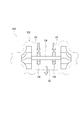
- the engine according to this embodiment includes a cylinder block 110, a cylinder head 120, and the like.
- a supercharger 130 is attached to one side surface of the cylinder head 120 of the engine.
- the engine is mounted on a vehicle such as an automobile.
- the cylinder block 110 is provided with a crankshaft 112, a piston 114, and the like.
- the cylinder head 120 is provided with an exhaust camshaft 122, an intake camshaft 124, and the like.
- the supercharger 130 is for increasing the pressure of the intake air of the engine.
- the supercharger 130 according to the present embodiment compresses air using engine exhaust gas, and sends the compressed air into the engine.
- the turbocharger 130 is a turbo-type supercharger, and is supported at both ends of the turbine shaft 134, a turbine shaft 134 disposed in the housing 132, two bearings 136 and 138 that support a midway portion of the turbine shaft 134. (See FIG. 2).
- the kind of supercharger is not limited to this embodiment, For example, you may be a mechanical supercharger which drives by transmitting the motive power of an engine.
- the lubricating oil supply mechanism 1 supplies lubricating oil A1 and A2 to such an engine (cylinder block 110 and cylinder head 120) and the supercharger 130.
- the lubricating oil supply mechanism 1 includes a block side oil pan 10, a block side oil pump 12, a block side oil passage 14, a head side oil pan 20, a head side oil pump 22, a head side oil passage 24, and the like.
- the block-side oil pan 10 is attached to the lower part of the cylinder block 110.
- the block-side oil pan 10 stores lubricating oil A1.
- the block side oil pump 12 is disposed in the cylinder block 110 of the engine.
- the block-side oil pump 12 is configured by, for example, a tocoloid pump that is connected to the crankshaft 112 of the engine and is driven by the rotation of the crankshaft 112. That is, the block-side oil pump 12 is driven by the engine and is driven at a rotational speed corresponding to the rotational speed of the engine.
- a relief valve (not shown) for returning the lubricating oil A1 from the discharge side of the block side oil pump 12 to the suction side according to the discharge pressure of the block side oil pump 12 is provided in the block side oil pump 12. .
- the block-side oil pump 12 communicates with the block-side oil pan 10 via an oil strainer 10a and piping.
- the block side oil pump 12 is driven by the engine to suck the lubricating oil A1 from the block side oil pan 10 and pumps the lubricating oil A1 toward the crankshaft 112 of the cylinder block 110 and the like.
- the lubricating oil A1 pumped by the block-side oil pump 12 is supplied to a main oil hole (not shown) that is a hole formed in the cylinder block 110 via the oil filter 12a.
- the oil filter 12a is provided with a relief valve (not shown) for circulating the lubricating oil A1 when the oil filter 12a is clogged.
- Lubricating oil A1 supplied to the main oil hole of the cylinder block 110 is branched and supplied to members arranged in the cylinder block 110, such as the crankshaft 112, the piston 114, the chain tensioner 116, the timing chain 118, and the like. Is done.
- the cylinder block 110 is formed with a plurality of passages that branch out from the main oil hole toward the crankshaft 112, the piston 114, and the like.
- the lubricating oil A1 is supplied to the cylinder block 110 through the passages.
- Lubricating oil A ⁇ b> 1 is collected in the block-side oil pan 10 after being supplied to the cylinder block 110.
- an oil drop (not shown) is formed as a passage that extends from below the crankshaft 112 and the piston 114 toward the block-side oil pan 10 and opens above the block-side oil pan 10.
- the lubricating oil A1 is collected in the block-side oil pan 10 through the oil drop.
- the block-side oil passage 14 is a route of the lubricating oil A1 that is supplied from the block-side oil pan 10 to the crankshaft 112, the piston 114, and the like of the cylinder block 110 and then recovered to the block-side oil pan 10.
- the block-side oil passage 14 includes a pipe that connects the block-side oil pump 12 and the oil strainer 10a, a main oil hole of the cylinder block 110, each passage formed in the cylinder block 110, and an oil drop. Composed of etc.
- the block side oil passage 14 functions as a first oil passage for supplying the lubricating oil A1 to the cylinder block 110 of the engine.
- block-side oil pan 10 is disposed on the block-side oil passage 14 and functions as a first oil pan in which the lubricating oil A1 flowing through the block-side oil passage 14 is stored.
- the head-side oil pan 20 is attached to the same side as the side to which the engine supercharger 130 is attached, for example, and is disposed below the supercharger 130. That is, the head side oil pan 20 is attached to one side surface of the cylinder head 120 of the engine.
- the head-side oil pan 20 stores lubricating oil A2.
- the head side oil pump 22 is composed of a commercially available electric pump.
- the head-side oil pump 22 is electrically connected to, for example, an ECU (Engine Control Unit) and a battery (not shown) mounted on the vehicle, and is driven by applying a voltage from the battery by an electric signal from the ECU.
- ECU Engine Control Unit
- battery not shown
- the head-side oil pump 22 is arranged inside the head-side oil pan 20, more specifically, in a state where the head-side oil pan 20 is immersed in the lubricating oil A2 of the head-side oil pan 20.
- the head-side oil pump 22 communicates with an oil hole (not shown) that is a hole formed in the cylinder head 120 via a pipe or the like.
- the head-side oil pump 22 is driven to pump the lubricating oil A2 from the head-side oil pan 20 toward the cylinder head 120.
- the head-side oil pump 22 functions as an oil pump that pumps the lubricating oil A2 stored in the head-side oil pan 20.
- the lubricating oil A2 pumped by the head-side oil pump 22 is branched into members disposed in the cylinder head 120 through the oil holes of the cylinder head 120, such as the exhaust camshaft 122 and the intake camshaft 124, respectively. Supplied.
- the cylinder head 120 is formed with a plurality of passages that branch out from the oil hole and extend toward the exhaust cam shaft 122 and the intake cam shaft 124 of the cylinder head 120.
- the lubricating oil A2 is supplied to the cylinder head 120 through each passage.
- Lubricating oil A ⁇ b> 2 is collected in the head-side oil pan 20 after being supplied to the cylinder head 120.
- an oil drop (not shown) is formed as a passage extending from below the exhaust cam shaft 122 and the intake cam shaft 124 toward the head side oil pan 20 and communicating with the head side oil pan 20.
- the lubricating oil A2 is collected in the head-side oil pan 20 through the oil drop.
- the lubricating oil A ⁇ b> 2 pumped by the head side oil pump 22 passes through the oil hole of the cylinder head 120 and is disposed in the supercharger 130, for example, the housing 132.
- the two bearings 136 and 138 that support the turbine shaft 134 are also branched and supplied.
- the cylinder head 120 is formed with a passage (not shown) that branches from the oil hole toward the supercharger 130 and extends.
- the housing 132 of the supercharger 130 is formed with a passage (not shown) that communicates with the passage of the cylinder head 120 and branches and extends toward the bearings 136 and 138 and the like.
- the lubricating oil A2 is supplied to the supercharger 130 through the passages (see arrow A2 shown on the upper side of FIG. 2).
- Lubricating oil A ⁇ b> 2 is collected in the head-side oil pan 20 after being supplied to the supercharger 130.
- an oil drop (not shown) is formed as a passage that extends from below the bearings 136 and 138 toward the head-side oil pan 20 and opens above the head-side oil pan 20. ing.
- the lubricating oil A2 passes through the oil drop and is collected in the head-side oil pan 20 (see arrow A2 shown on the lower side of FIG. 2).
- the head-side oil passage 24 is a route of the lubricating oil A2 that is supplied from the head-side oil pan 20 to the cylinder head 120 and the supercharger 130 and then collected by the head-side oil pan 20.
- the head side oil passage 24 includes a pipe that connects the head side oil pump 22 and the cylinder head 120, an oil hole of the cylinder head 120, each passage of the cylinder head 120 and the supercharger 130, and oil. Composed by dropping.
- the head side oil passage 24 functions as a second oil passage for supplying the lubricating oil A2 to the supercharger 130.
- the head-side oil pan 20 is disposed on the head-side oil passage 24 and functions as a second oil pan in which the lubricating oil A2 flowing through the head-side oil passage 24 is stored.
- the head-side oil pan 20 is disposed below the supercharger 130.
- the lubricating oil supply mechanism 1 can return the lubricating oil A2 to the head-side oil pan 20 only by dropping the lubricating oil A2 that lubricates the bearings 136 and 138 of the supercharger 130 by its own weight.
- the lubricating oil supply mechanism 1 can recover the lubricating oil A2 efficiently (without being separately pumped to the head-side oil pan 20 by a pump or the like).
- the lubricant oil A1 when the lubricant oil A1 is supplied to the cylinder block 110, the lubricant oil A1 contains a lot of sludge.
- the lubricating oil supply mechanism 1 does not supply one oil pan lubricating oil to the cylinder block 110 and the supercharger 130 by branching one oil passage, but two independent oils.
- the lubricating oils A1 and A2 of the two oil pans 10 and 20 are separately supplied from the paths 14 and 24.
- the lubricating oil supply mechanism 1 divides the lubricating oil passage into two parts so that the lubricating oil A1 supplied to the cylinder block 110 is not supplied to the supercharger 130. Yes.
- the lubricating oil supply mechanism 1 supplies the lubricating oil A1 containing a large amount of sludge only to the cylinder block 110. That is, the lubricating oil supply mechanism 1 can supply the supercharger 130 with the lubricating oil A2 that does not contain much sludge.
- the lubricating oil supply mechanism 1 can effectively lubricate the bearings 136 and 138 that support the turbine shaft 134 of the supercharger 130, and can suppress the occurrence of coking in the bearings 136 and 138.
- the lubricating oil supply mechanism 1 can improve the oxidation deterioration resistance of the lubricating oil A2 supplied to the supercharger 130.
- the lubricating oil supply mechanism 1 can improve the mechanical efficiency of the supercharger 130.
- the lubricating oil supply mechanism 1 configures the block side oil passage 14 and the head side oil passage 24 as independent oil passages.
- the head-side oil pump 22 is disposed in a state of being immersed in the lubricating oil A2 stored in the head-side oil pan 20.
- the lubricating oil supply mechanism 1 warms the lubricating oil A2 of the head side oil pan 20 by utilizing the heat generated by the head side oil pump 22 when driving the engine placed in a low temperature environment. be able to.
- the lubricating oil supply mechanism 1 can quickly reduce the viscosity of the lubricating oil A2 even in a low temperature environment, the friction of the supercharger 130 can be reduced.
- the oil pump according to the present invention does not suck air in the second oil pan (head-side oil pan 20 according to the present embodiment) during driving. What is necessary is just to be immersed in the lubricating oil of a 2nd oil pan.
- the “state immersed in the lubricating oil A2” indicates a state where the suction port of the head side oil pump 22 is immersed in the lubricating oil A2 when the head side oil pump 22 is driven. Accordingly, the head-side oil pump 22 does not necessarily have to be entirely immersed in the lubricating oil A2 of the head-side oil pan 20 during driving. For example, the upper end portion may protrude from the oil surface during driving. .
- the lubricating oil supply mechanism 1 employs an electric oil pump as such a head-side oil pump 22.
- the head side oil pump 22 can pump the amount of the lubricating oil A2 according to the applied voltage.
- the head-side oil pump 22 can stably supply the lubricating oil A2 to the supercharger 130 regardless of the rotational speed of the crankshaft 112, that is, the operating state of the engine. That is, the head-side oil pump 22 can always supply the lubricating oil A2 adjusted to an appropriate amount to the supercharger 130.
- the lubricating oil supply mechanism 1 can reduce the friction of the supercharger 130, the mechanical efficiency of the supercharger 130 can be effectively improved.
- the lubricating oil supply mechanism 1 can cool the head-side oil pump 22 by the lubricating oil A2 stored in the head-side oil pan 20. Therefore, the lubricating oil supply mechanism 1 can improve the cooling efficiency of the head-side oil pump 22.
- the lubricating oil supply mechanism 1 has a seal for preventing the lubricating oil A2 from leaking to the head side oil pump 22 as compared with the case where the head side oil pump 22 is arranged at a position away from the head side oil pan 20. There is no need to attach a member.
- the lubricating oil supply mechanism 1 can improve the mechanical efficiency of the supercharger 130 by disposing the electric head-side oil pump 22 soaked in the lubricating oil A2 of the head-side oil pan 20.
- the life of the head-side oil pump 22 can be extended and the number of parts can be reduced.
- the lubricating oil supply mechanism 1 also supplies the cylinder head 120 with the lubricating oil A2 that lubricates the supercharger 130.
- the lubricating oil supply mechanism 1 can supply the cylinder head 120 with the lubricating oil A2 that does not contain much sludge. For this reason, the lubricating oil supply mechanism 1 can effectively lubricate the exhaust camshaft 122, the intake camshaft 124, and the like of the cylinder head 120.
- the lubricating oil supply mechanism 1 can improve the oxidation deterioration resistance of the lubricating oil A2 supplied to the cylinder head 120.
- the lubricating oil supply mechanism 1 can improve the mechanical efficiency of members (for example, the exhaust camshaft 122 and the intake camshaft 124) disposed in the cylinder head 120.
- the head side oil passage 24 is formed as an oil passage for supplying the lubricating oil A2 stored in the head side oil pan 20 to the cylinder head 120 of the engine.
- the configuration of the lubricating oil supply mechanism is not limited to the present embodiment as long as the lubricating oil passage supplied to the cylinder block and the lubricating oil supply passage supplied to the supercharger are isolated from each other. .
- the lubricating oil supply mechanism includes a first oil passage 214 that supplies the lubricating oil A 201 to the cylinder block 110 and the cylinder head 120, as in the lubricating oil supply mechanism 201 according to another embodiment shown in FIG.
- a second oil passage 224 for supplying the lubricating oil A202 only to the machine 130 may be provided.
- the present invention can be applied to a lubricating oil supply mechanism that supplies lubricating oil to an engine and a supercharger attached to the engine.
- Lubricating oil supply mechanism 10 Block side oil pan (first oil pan) 14 Block side oil passage (first oil passage) 20 Head side oil pan (second oil pan) 24 Head side oil passage (second oil passage) 110 Cylinder block 130 Supercharger A1 Lubricating oil (lubricating oil flowing through the first oil passage) A2 Lubricating oil (Lubricating oil flowing through the second oil passage)
Landscapes
- Engineering & Computer Science (AREA)
- Mechanical Engineering (AREA)
- General Engineering & Computer Science (AREA)
- Chemical & Material Sciences (AREA)
- Combustion & Propulsion (AREA)
- Lubrication Of Internal Combustion Engines (AREA)
- Lubrication Details And Ventilation Of Internal Combustion Engines (AREA)
- Supercharger (AREA)
Abstract
Provided is a lubricating oil supply mechanism that can improve the mechanical efficiency of a supercharger. A lubricating oil supply mechanism (1) that supplies lubricating oil (A1, A2) to an engine and to a supercharger (130) that is attached to the engine, and that is provided with a block-side oil path (14) that is for supplying lubricating oil (A1) to a cylinder block (110) of the engine, a block-side oil pan (10) that is arranged along the route of the block-side oil path (14) and that collects the lubricating oil (A1) that flows in the block-side oil path (14), a head-side oil path (24) that is for supplying lubricating oil (A2) to the supercharger (130), and a head-side oil pan (20) that is arranged along the route of the head-side oil path (24) and that collects the lubricating oil (A2) that flows in the head-side oil path (24). The block-side oil path (14) and the head-side oil path (24) are configured as independent oil paths.
Description
本発明は、エンジンおよびエンジンに取り付けられる過給機に潤滑油を供給する潤滑油供給機構に関する。
The present invention relates to a lubricating oil supply mechanism that supplies lubricating oil to an engine and a supercharger attached to the engine.
従来、エンジンおよびエンジンに取り付けられる過給機には、例えば、エンジンに設けられるオイルパンから潤滑油が供給される(例えば、特許文献1参照)。
Conventionally, lubricating oil is supplied to an engine and a turbocharger attached to the engine, for example, from an oil pan provided in the engine (see, for example, Patent Document 1).
特許文献1に開示される技術では、エンジンより動力が伝達されて駆動するメインオイルポンプによって、エンジンおよび過給機に潤滑油を供給する。特許文献1に開示される技術では、メインオイルポンプが供給する潤滑油量が十分ではない場合(例えば、運転条件等によって潤滑油の粘度が高くなってしまい、通常よりも多い量の潤滑油が必要となる場合等)に補助オイルポンプを駆動させる。
In the technique disclosed in Patent Document 1, lubricating oil is supplied to an engine and a supercharger by a main oil pump that is driven by transmission of power from the engine. In the technique disclosed in Patent Document 1, when the amount of lubricating oil supplied by the main oil pump is not sufficient (for example, the viscosity of the lubricating oil increases due to operating conditions or the like, and a larger amount of lubricating oil than usual is generated. If necessary, drive the auxiliary oil pump.
これにより、特許文献1に開示される技術では、メインオイルポンプでの潤滑油供給量の不足分を補助オイルポンプで補っている。
Thus, in the technique disclosed in Patent Document 1, the shortage of the lubricating oil supply amount in the main oil pump is compensated by the auxiliary oil pump.
ここで、エンジンに潤滑油を供給することにより、潤滑油には多くのスラッジが含まれてしまう。
Here, by supplying lubricating oil to the engine, the lubricating oil contains a lot of sludge.
特許文献1に開示される技術では、エンジンおよび過給機に供給した潤滑油を同じオイルパンに戻す構成であるため、多くのスラッジが含まれた潤滑油を過給機に供給してしまうこととなる。
In the technique disclosed in Patent Document 1, since the lubricating oil supplied to the engine and the supercharger is returned to the same oil pan, the lubricating oil containing a lot of sludge is supplied to the supercharger. It becomes.
この場合には、過給機のタービン軸を支持する軸受を効果的に潤滑できない可能性がある。従って、特許文献1に開示される技術では、過給機の機械効率を向上させることができない可能性がある。
In this case, there is a possibility that the bearing that supports the turbine shaft of the turbocharger cannot be effectively lubricated. Therefore, with the technique disclosed in Patent Document 1, there is a possibility that the mechanical efficiency of the supercharger cannot be improved.
本発明は、以上の如き状況を鑑みてなされたものであり、過給機の機械効率を向上させることができる潤滑油供給機構を提供するものである。
The present invention has been made in view of the above situation, and provides a lubricating oil supply mechanism capable of improving the mechanical efficiency of a supercharger.
本発明の潤滑油供給機構は、エンジンおよび前記エンジンに取り付けられる過給機に潤滑油を供給する潤滑油供給機構であって、前記エンジンのシリンダブロックに潤滑油を供給するための第一の油路と、前記第一の油路の経路上に配置され、前記第一の油路を流れる潤滑油が貯溜される第一のオイルパンと、前記過給機に潤滑油を供給するための第二の油路と、前記第二の油路の経路上に配置され、前記第二の油路を流れる潤滑油が貯溜される第二のオイルパンと、を具備し、前記第一の油路と前記第二の油路とを互いに独立した油路として構成する、ものである。
The lubricating oil supply mechanism of the present invention is a lubricating oil supply mechanism that supplies lubricating oil to an engine and a supercharger attached to the engine, and is a first oil for supplying lubricating oil to a cylinder block of the engine. A first oil pan disposed on the path of the first oil path and storing the lubricating oil flowing through the first oil path; and a first oil pan for supplying the supercharger with the lubricating oil. And a second oil pan that is disposed on the second oil passage and stores lubricating oil flowing through the second oil passage, and the first oil passage. And the second oil passage are configured as independent oil passages.
本発明の潤滑油供給機構は、前記第二のオイルパンに貯溜される潤滑油に浸かった状態で配置され、前記第二のオイルパンに貯溜される潤滑油を圧送する電動式のオイルポンプと、をさらに具備する、ものである。
The lubricating oil supply mechanism of the present invention is disposed in a state immersed in the lubricating oil stored in the second oil pan, and an electric oil pump that pumps the lubricating oil stored in the second oil pan; Are further provided.
本発明の潤滑油供給機構においては、前記第二の油路は、前記エンジンのシリンダヘッドに、前記第二のオイルパンに貯溜される潤滑油を供給するための油路として形成される、ものである。
In the lubricating oil supply mechanism of the present invention, the second oil passage is formed as an oil passage for supplying lubricating oil stored in the second oil pan to the cylinder head of the engine. It is.
本発明の潤滑油供給機構においては、前記第二のオイルパンは、前記過給機の下方に配置される、ものである。
In the lubricating oil supply mechanism of the present invention, the second oil pan is disposed below the supercharger.
本発明の効果として、以下に示すような効果を奏する。
As the effects of the present invention, the following effects are obtained.
本発明の潤滑油供給機構においては、過給機の機械効率を向上させることができる。
In the lubricating oil supply mechanism of the present invention, the mechanical efficiency of the supercharger can be improved.
本発明の潤滑油供給機構においては、過給機の機械効率を効果的に向上させることができる。
In the lubricating oil supply mechanism of the present invention, the mechanical efficiency of the supercharger can be effectively improved.
本発明の潤滑油供給機構においては、シリンダヘッド内に配置される部材の機械効率を向上させることができる。
In the lubricating oil supply mechanism of the present invention, the mechanical efficiency of the members arranged in the cylinder head can be improved.
本発明の潤滑油供給機構においては、効率的に潤滑油を循環させることができる。
In the lubricating oil supply mechanism of the present invention, the lubricating oil can be circulated efficiently.
以下では、本発明の一実施形態に係る潤滑油供給機構1について説明する。
Hereinafter, the lubricating oil supply mechanism 1 according to an embodiment of the present invention will be described.
図1に示すように、本実施形態に係るエンジンは、シリンダブロック110およびシリンダヘッド120等を具備する。エンジンのシリンダヘッド120の一側面には、過給機130が取り付けられる。
As shown in FIG. 1, the engine according to this embodiment includes a cylinder block 110, a cylinder head 120, and the like. A supercharger 130 is attached to one side surface of the cylinder head 120 of the engine.
エンジンは、例えば、自動車等の車両に搭載される。シリンダブロック110には、クランクシャフト112およびピストン114等が設けられる。シリンダヘッド120には、エキゾーストカムシャフト122およびインテークカムシャフト124等が設けられる。
The engine is mounted on a vehicle such as an automobile. The cylinder block 110 is provided with a crankshaft 112, a piston 114, and the like. The cylinder head 120 is provided with an exhaust camshaft 122, an intake camshaft 124, and the like.
過給機130は、エンジンの吸引空気の圧力を高めるためのものである。本実施形態に係る過給機130は、エンジンの排気ガスを利用して空気を圧縮し、当該圧縮した空気をエンジン内に送るものである。過給機130は、ターボ式の過給機であり、ハウジング132内に配置されるタービン軸134、タービン軸134の中途部を支持する二つの軸受136・138、タービン軸134の両端部に支持されるホイール等を具備する(図2参照)。
The supercharger 130 is for increasing the pressure of the intake air of the engine. The supercharger 130 according to the present embodiment compresses air using engine exhaust gas, and sends the compressed air into the engine. The turbocharger 130 is a turbo-type supercharger, and is supported at both ends of the turbine shaft 134, a turbine shaft 134 disposed in the housing 132, two bearings 136 and 138 that support a midway portion of the turbine shaft 134. (See FIG. 2).
なお、過給機の種類は、本実施形態に限定されるものでなく、例えば、エンジンの動力が伝達されて駆動する機械式の過給機であっても構わない。
In addition, the kind of supercharger is not limited to this embodiment, For example, you may be a mechanical supercharger which drives by transmitting the motive power of an engine.
潤滑油供給機構1は、このようなエンジン(シリンダブロック110およびシリンダヘッド120)および過給機130に潤滑油A1・A2を供給するものである。
The lubricating oil supply mechanism 1 supplies lubricating oil A1 and A2 to such an engine (cylinder block 110 and cylinder head 120) and the supercharger 130.
潤滑油供給機構1は、ブロック側オイルパン10、ブロック側オイルポンプ12、ブロック側油路14、ヘッド側オイルパン20、ヘッド側オイルポンプ22、およびヘッド側油路24等を具備する。
The lubricating oil supply mechanism 1 includes a block side oil pan 10, a block side oil pump 12, a block side oil passage 14, a head side oil pan 20, a head side oil pump 22, a head side oil passage 24, and the like.
ブロック側オイルパン10は、シリンダブロック110の下部に取り付けられる。ブロック側オイルパン10には、潤滑油A1が貯溜される。
The block-side oil pan 10 is attached to the lower part of the cylinder block 110. The block-side oil pan 10 stores lubricating oil A1.
ブロック側オイルポンプ12は、エンジンのシリンダブロック110内に配置される。ブロック側オイルポンプ12は、例えば、エンジンのクランクシャフト112と連結され、クランクシャフト112の回転によって駆動するトコロイドポンプ等によって構成される。つまり、ブロック側オイルポンプ12は、エンジンによって駆動されるとともに、当該エンジンの回転数に応じた回転数で駆動される。
The block side oil pump 12 is disposed in the cylinder block 110 of the engine. The block-side oil pump 12 is configured by, for example, a tocoloid pump that is connected to the crankshaft 112 of the engine and is driven by the rotation of the crankshaft 112. That is, the block-side oil pump 12 is driven by the engine and is driven at a rotational speed corresponding to the rotational speed of the engine.
ブロック側オイルポンプ12内には、当該ブロック側オイルポンプ12の吐出圧に応じて、当該ブロック側オイルポンプ12の吐出側から吸入側へと潤滑油A1を戻すリリーフバルブ(不図示)が設けられる。
A relief valve (not shown) for returning the lubricating oil A1 from the discharge side of the block side oil pump 12 to the suction side according to the discharge pressure of the block side oil pump 12 is provided in the block side oil pump 12. .
ブロック側オイルポンプ12は、オイルストレーナ10aおよび配管等を介してブロック側オイルパン10と連通する。ブロック側オイルポンプ12は、エンジンの駆動によって駆動することでブロック側オイルパン10より潤滑油A1を吸引し、シリンダブロック110のクランクシャフト112等に向けて潤滑油A1を圧送する。
The block-side oil pump 12 communicates with the block-side oil pan 10 via an oil strainer 10a and piping. The block side oil pump 12 is driven by the engine to suck the lubricating oil A1 from the block side oil pan 10 and pumps the lubricating oil A1 toward the crankshaft 112 of the cylinder block 110 and the like.
ブロック側オイルポンプ12によって圧送される潤滑油A1は、オイルフィルター12aを介して、シリンダブロック110に形成される孔であるメインオイルホール(不図示)へと供給される。オイルフィルター12aには、当該オイルフィルター12aに目詰まりが生じた際に潤滑油A1を流通させるためのリリーフバルブ(不図示)が設けられる。
The lubricating oil A1 pumped by the block-side oil pump 12 is supplied to a main oil hole (not shown) that is a hole formed in the cylinder block 110 via the oil filter 12a. The oil filter 12a is provided with a relief valve (not shown) for circulating the lubricating oil A1 when the oil filter 12a is clogged.
シリンダブロック110のメインオイルホールに供給された潤滑油A1は、シリンダブロック110内に配置される部材、例えば、クランクシャフト112、ピストン114、チェーンテンショナー116、およびタイミングチェーン118等にそれぞれ分岐して供給される。
Lubricating oil A1 supplied to the main oil hole of the cylinder block 110 is branched and supplied to members arranged in the cylinder block 110, such as the crankshaft 112, the piston 114, the chain tensioner 116, the timing chain 118, and the like. Is done.
つまり、シリンダブロック110には、メインオイルホールよりクランクシャフト112およびピストン114等に向けて分岐して伸びる複数の通路が形成されている。潤滑油A1は、当該各通路を通ってシリンダブロック110に供給される。
That is, the cylinder block 110 is formed with a plurality of passages that branch out from the main oil hole toward the crankshaft 112, the piston 114, and the like. The lubricating oil A1 is supplied to the cylinder block 110 through the passages.
潤滑油A1は、シリンダブロック110に供給された後でブロック側オイルパン10に回収される。
Lubricating oil A <b> 1 is collected in the block-side oil pan 10 after being supplied to the cylinder block 110.
つまり、シリンダブロック110には、クランクシャフト112およびピストン114等の下方よりブロック側オイルパン10に向けて伸びるとともに、ブロック側オイルパン10の上方で開口する通路として、オイル落とし(不図示)が形成されている。潤滑油A1は、当該オイル落としを通ってブロック側オイルパン10に回収される。
That is, in the cylinder block 110, an oil drop (not shown) is formed as a passage that extends from below the crankshaft 112 and the piston 114 toward the block-side oil pan 10 and opens above the block-side oil pan 10. Has been. The lubricating oil A1 is collected in the block-side oil pan 10 through the oil drop.
ブロック側油路14は、ブロック側オイルパン10からシリンダブロック110のクランクシャフト112およびピストン114等に供給され、その後、ブロック側オイルパン10に回収されるまでの潤滑油A1の経路である。
The block-side oil passage 14 is a route of the lubricating oil A1 that is supplied from the block-side oil pan 10 to the crankshaft 112, the piston 114, and the like of the cylinder block 110 and then recovered to the block-side oil pan 10.
つまり、本実施形態に係るブロック側油路14は、ブロック側オイルポンプ12とオイルストレーナ10aとを連通する配管、シリンダブロック110のメインオイルホール、シリンダブロック110に形成される各通路、およびオイル落とし等によって構成される。
That is, the block-side oil passage 14 according to the present embodiment includes a pipe that connects the block-side oil pump 12 and the oil strainer 10a, a main oil hole of the cylinder block 110, each passage formed in the cylinder block 110, and an oil drop. Composed of etc.
このように、本実施形態に係るブロック側油路14は、エンジンのシリンダブロック110に潤滑油A1を供給するための第一の油路として機能する。
Thus, the block side oil passage 14 according to the present embodiment functions as a first oil passage for supplying the lubricating oil A1 to the cylinder block 110 of the engine.
また、本実施形態に係るブロック側オイルパン10は、ブロック側油路14の経路上に配置され、ブロック側油路14を流れる潤滑油A1が貯溜される第一のオイルパンとして機能する。
Further, the block-side oil pan 10 according to the present embodiment is disposed on the block-side oil passage 14 and functions as a first oil pan in which the lubricating oil A1 flowing through the block-side oil passage 14 is stored.
ヘッド側オイルパン20は、例えば、エンジンの過給機130が取り付けられる側面と同じ面に取り付けられ、過給機130の下方に配置される。つまり、ヘッド側オイルパン20は、エンジンのシリンダヘッド120一側面に取り付けられる。ヘッド側オイルパン20には、潤滑油A2が貯溜される。
The head-side oil pan 20 is attached to the same side as the side to which the engine supercharger 130 is attached, for example, and is disposed below the supercharger 130. That is, the head side oil pan 20 is attached to one side surface of the cylinder head 120 of the engine. The head-side oil pan 20 stores lubricating oil A2.
ヘッド側オイルポンプ22は、市販の電動式のポンプによって構成される。ヘッド側オイルポンプ22は、例えば、車両に搭載されるECU(Engine Control Unit)およびバッテリ(不図示)と電気的に接続され、ECUからの電気信号によってバッテリから電圧が印加されて駆動する。
The head side oil pump 22 is composed of a commercially available electric pump. The head-side oil pump 22 is electrically connected to, for example, an ECU (Engine Control Unit) and a battery (not shown) mounted on the vehicle, and is driven by applying a voltage from the battery by an electric signal from the ECU.
本実施形態に係るヘッド側オイルポンプ22は、ヘッド側オイルパン20の内側、より詳細には、ヘッド側オイルパン20の潤滑油A2に浸かった状態で配置される。ヘッド側オイルポンプ22は、配管等を介してシリンダヘッド120に形成される孔であるオイルホール(不図示)と連通する。
The head-side oil pump 22 according to the present embodiment is arranged inside the head-side oil pan 20, more specifically, in a state where the head-side oil pan 20 is immersed in the lubricating oil A2 of the head-side oil pan 20. The head-side oil pump 22 communicates with an oil hole (not shown) that is a hole formed in the cylinder head 120 via a pipe or the like.
ヘッド側オイルポンプ22は、駆動することでヘッド側オイルパン20よりシリンダヘッド120に向けて潤滑油A2を圧送する。
The head-side oil pump 22 is driven to pump the lubricating oil A2 from the head-side oil pan 20 toward the cylinder head 120.
つまり、本実施形態に係るヘッド側オイルポンプ22は、ヘッド側オイルパン20に貯溜される潤滑油A2を圧送するオイルポンプとして機能する。
That is, the head-side oil pump 22 according to the present embodiment functions as an oil pump that pumps the lubricating oil A2 stored in the head-side oil pan 20.
ヘッド側オイルポンプ22によって圧送される潤滑油A2は、シリンダヘッド120のオイルホールを通ってシリンダヘッド120内に配置される部材、例えば、エキゾーストカムシャフト122およびインテークカムシャフト124等にそれぞれ分岐して供給される。
The lubricating oil A2 pumped by the head-side oil pump 22 is branched into members disposed in the cylinder head 120 through the oil holes of the cylinder head 120, such as the exhaust camshaft 122 and the intake camshaft 124, respectively. Supplied.
つまり、シリンダヘッド120には、オイルホールよりシリンダヘッド120のエキゾーストカムシャフト122およびインテークカムシャフト124等に向けて分岐して伸びる複数の通路が形成されている。潤滑油A2は、当該各通路を通ってシリンダヘッド120に供給される。
That is, the cylinder head 120 is formed with a plurality of passages that branch out from the oil hole and extend toward the exhaust cam shaft 122 and the intake cam shaft 124 of the cylinder head 120. The lubricating oil A2 is supplied to the cylinder head 120 through each passage.
潤滑油A2は、シリンダヘッド120に供給された後でヘッド側オイルパン20に回収される。
Lubricating oil A <b> 2 is collected in the head-side oil pan 20 after being supplied to the cylinder head 120.
つまり、シリンダヘッド120には、エキゾーストカムシャフト122およびインテークカムシャフト124等の下方よりヘッド側オイルパン20に向けて伸びるとともにヘッド側オイルパン20と連通する通路として、オイル落とし(不図示)が形成されている。潤滑油A2は、当該オイル落としを通ってヘッド側オイルパン20に回収される。
That is, in the cylinder head 120, an oil drop (not shown) is formed as a passage extending from below the exhaust cam shaft 122 and the intake cam shaft 124 toward the head side oil pan 20 and communicating with the head side oil pan 20. Has been. The lubricating oil A2 is collected in the head-side oil pan 20 through the oil drop.
また、図1および図2に示すように、ヘッド側オイルポンプ22によって圧送される潤滑油A2は、シリンダヘッド120のオイルホールを通って過給機130内に配置される部材、例えば、ハウジング132内のタービン軸134を支持する二つの軸受136・138等にもそれぞれ分岐して供給される。
As shown in FIGS. 1 and 2, the lubricating oil A <b> 2 pumped by the head side oil pump 22 passes through the oil hole of the cylinder head 120 and is disposed in the supercharger 130, for example, the housing 132. The two bearings 136 and 138 that support the turbine shaft 134 are also branched and supplied.
つまり、シリンダヘッド120には、オイルホールより過給機130に向けて分岐して伸びる通路(不図示)が形成されている。過給機130のハウジング132には、前記シリンダヘッド120の通路と連通し、軸受136・138等に向けて分岐して伸びる通路(不図示)が形成されている。潤滑油A2は、当該各通路を通って過給機130に供給される(図2の上側に示す矢印A2参照)。
That is, the cylinder head 120 is formed with a passage (not shown) that branches from the oil hole toward the supercharger 130 and extends. The housing 132 of the supercharger 130 is formed with a passage (not shown) that communicates with the passage of the cylinder head 120 and branches and extends toward the bearings 136 and 138 and the like. The lubricating oil A2 is supplied to the supercharger 130 through the passages (see arrow A2 shown on the upper side of FIG. 2).
潤滑油A2は、過給機130に供給された後でヘッド側オイルパン20に回収される。
Lubricating oil A <b> 2 is collected in the head-side oil pan 20 after being supplied to the supercharger 130.
つまり、過給機130には、軸受136・138等の下方よりヘッド側オイルパン20に向けて伸びるとともに、ヘッド側オイルパン20の上方で開口する通路として、オイル落とし(不図示)が形成されている。潤滑油A2は、当該オイル落としを通ってヘッド側オイルパン20に回収される(図2の下側に示す矢印A2参照)。
That is, in the supercharger 130, an oil drop (not shown) is formed as a passage that extends from below the bearings 136 and 138 toward the head-side oil pan 20 and opens above the head-side oil pan 20. ing. The lubricating oil A2 passes through the oil drop and is collected in the head-side oil pan 20 (see arrow A2 shown on the lower side of FIG. 2).
ヘッド側油路24は、ヘッド側オイルパン20からシリンダヘッド120および過給機130に供給され、その後、ヘッド側オイルパン20に回収されるまでの潤滑油A2の経路である。
The head-side oil passage 24 is a route of the lubricating oil A2 that is supplied from the head-side oil pan 20 to the cylinder head 120 and the supercharger 130 and then collected by the head-side oil pan 20.
つまり、本実施形態に係るヘッド側油路24は、ヘッド側オイルポンプ22とシリンダヘッド120とを連通する配管、シリンダヘッド120のオイルホール、シリンダヘッド120および過給機130の各通路、およびオイル落とし等によって構成される。
That is, the head side oil passage 24 according to the present embodiment includes a pipe that connects the head side oil pump 22 and the cylinder head 120, an oil hole of the cylinder head 120, each passage of the cylinder head 120 and the supercharger 130, and oil. Composed by dropping.
このように、本実施形態に係るヘッド側油路24は、過給機130に潤滑油A2を供給するための第二の油路として機能する。
Thus, the head side oil passage 24 according to the present embodiment functions as a second oil passage for supplying the lubricating oil A2 to the supercharger 130.
また、本実施形態に係るヘッド側オイルパン20は、ヘッド側油路24の経路上に配置され、ヘッド側油路24を流れる潤滑油A2が貯溜される第二のオイルパンとして機能する。
The head-side oil pan 20 according to the present embodiment is disposed on the head-side oil passage 24 and functions as a second oil pan in which the lubricating oil A2 flowing through the head-side oil passage 24 is stored.
本実施形態に係るヘッド側オイルパン20は、過給機130の下方に配置されている。
The head-side oil pan 20 according to the present embodiment is disposed below the supercharger 130.
このため、潤滑油供給機構1は、過給機130の軸受136・138等を潤滑した潤滑油A2を自重によって落下させるだけで、潤滑油A2をヘッド側オイルパン20に戻すことができる。
For this reason, the lubricating oil supply mechanism 1 can return the lubricating oil A2 to the head-side oil pan 20 only by dropping the lubricating oil A2 that lubricates the bearings 136 and 138 of the supercharger 130 by its own weight.
従って、潤滑油供給機構1は、効率的に(別途ポンプ等によってヘッド側オイルパン20に圧送することなく)潤滑油A2を回収できる。
Therefore, the lubricating oil supply mechanism 1 can recover the lubricating oil A2 efficiently (without being separately pumped to the head-side oil pan 20 by a pump or the like).
ここで、シリンダブロック110に潤滑油A1を供給することにより、潤滑油A1には多くのスラッジが含まれてしまう。
Here, when the lubricant oil A1 is supplied to the cylinder block 110, the lubricant oil A1 contains a lot of sludge.
そこで、本実施形態に係る潤滑油供給機構1は、一つの油路を分岐させてシリンダブロック110および過給機130に一つのオイルパンの潤滑油を供給するのではなく、独立した二つの油路14・24より二つのオイルパン10・20の潤滑油A1・A2を別々に供給する構成としている。
Accordingly, the lubricating oil supply mechanism 1 according to the present embodiment does not supply one oil pan lubricating oil to the cylinder block 110 and the supercharger 130 by branching one oil passage, but two independent oils. The lubricating oils A1 and A2 of the two oil pans 10 and 20 are separately supplied from the paths 14 and 24.
つまり、本実施形態に係る潤滑油供給機構1は、シリンダブロック110に供給される潤滑油A1が過給機130に供給されることがないように、潤滑油の油路を二つに分けている。
That is, the lubricating oil supply mechanism 1 according to the present embodiment divides the lubricating oil passage into two parts so that the lubricating oil A1 supplied to the cylinder block 110 is not supplied to the supercharger 130. Yes.
これによれば、潤滑油供給機構1は、スラッジが多く含まれる潤滑油A1をシリンダブロック110だけに供給することとなる。つまり、潤滑油供給機構1は、スラッジが多く含まれない潤滑油A2を過給機130に供給できる。
According to this, the lubricating oil supply mechanism 1 supplies the lubricating oil A1 containing a large amount of sludge only to the cylinder block 110. That is, the lubricating oil supply mechanism 1 can supply the supercharger 130 with the lubricating oil A2 that does not contain much sludge.
このため、潤滑油供給機構1は、過給機130のタービン軸134を支持する軸受136・138を効果的に潤滑できるとともに、軸受136・138でのコーキングの発生を抑制できる。
Therefore, the lubricating oil supply mechanism 1 can effectively lubricate the bearings 136 and 138 that support the turbine shaft 134 of the supercharger 130, and can suppress the occurrence of coking in the bearings 136 and 138.
従って、潤滑油供給機構1は、過給機130に供給する潤滑油A2の耐酸化劣化性を向上できる。
Therefore, the lubricating oil supply mechanism 1 can improve the oxidation deterioration resistance of the lubricating oil A2 supplied to the supercharger 130.
つまり、潤滑油供給機構1は、過給機130の機械効率を向上させることができる。
That is, the lubricating oil supply mechanism 1 can improve the mechanical efficiency of the supercharger 130.
このように、潤滑油供給機構1は、ブロック側油路14とヘッド側油路24とを互いに独立した油路として構成する。
Thus, the lubricating oil supply mechanism 1 configures the block side oil passage 14 and the head side oil passage 24 as independent oil passages.
前述のように、本実施形態に係るヘッド側オイルポンプ22は、ヘッド側オイルパン20に貯溜される潤滑油A2に浸かった状態で配置されている。
As described above, the head-side oil pump 22 according to this embodiment is disposed in a state of being immersed in the lubricating oil A2 stored in the head-side oil pan 20.
これによれば、潤滑油供給機構1は、低温環境下に置かれたエンジンを駆動させるとき等において、ヘッド側オイルポンプ22の発熱を利用して、ヘッド側オイルパン20の潤滑油A2を温めることができる。
According to this, the lubricating oil supply mechanism 1 warms the lubricating oil A2 of the head side oil pan 20 by utilizing the heat generated by the head side oil pump 22 when driving the engine placed in a low temperature environment. be able to.
従って、潤滑油供給機構1は、低温環境下においても速やかに潤滑油A2の粘度を下げることができるため、過給機130のフリクションを低減できる。
Therefore, since the lubricating oil supply mechanism 1 can quickly reduce the viscosity of the lubricating oil A2 even in a low temperature environment, the friction of the supercharger 130 can be reduced.
なお、本発明に係るオイルポンプ(本実施形態に係るヘッド側オイルポンプ22)は、駆動時に第二のオイルパン(本実施形態に係るヘッド側オイルパン20)内の空気を吸引しない程度に、第二のオイルパンの潤滑油に浸かっていればよい。
The oil pump according to the present invention (head-side oil pump 22 according to the present embodiment) does not suck air in the second oil pan (head-side oil pan 20 according to the present embodiment) during driving. What is necessary is just to be immersed in the lubricating oil of a 2nd oil pan.
つまり、本実施形態において、「潤滑油A2に浸かった状態」とは、ヘッド側オイルポンプ22の吸引口が、ヘッド側オイルポンプ22の駆動時に潤滑油A2に浸かっている状態を指す。従って、ヘッド側オイルポンプ22は、駆動時に必ずしも全体がヘッド側オイルパン20の潤滑油A2に浸かっている状態でなくてもよく、例えば、駆動時に上端部が油面から出ていても構わない。
That is, in the present embodiment, the “state immersed in the lubricating oil A2” indicates a state where the suction port of the head side oil pump 22 is immersed in the lubricating oil A2 when the head side oil pump 22 is driven. Accordingly, the head-side oil pump 22 does not necessarily have to be entirely immersed in the lubricating oil A2 of the head-side oil pan 20 during driving. For example, the upper end portion may protrude from the oil surface during driving. .
潤滑油供給機構1は、このようなヘッド側オイルポンプ22として電動式のオイルポンプを採用している。
The lubricating oil supply mechanism 1 employs an electric oil pump as such a head-side oil pump 22.
これによれば、ヘッド側オイルポンプ22は、印加電圧に応じた量の潤滑油A2を圧送できる。
According to this, the head side oil pump 22 can pump the amount of the lubricating oil A2 according to the applied voltage.
このため、ヘッド側オイルポンプ22は、クランクシャフト112の回転数、すなわち、エンジンの運転状態に関わらず、過給機130に潤滑油A2を安定して供給できる。つまり、ヘッド側オイルポンプ22は、過給機130に対して、常に適正量に調整された潤滑油A2を供給できる。
For this reason, the head-side oil pump 22 can stably supply the lubricating oil A2 to the supercharger 130 regardless of the rotational speed of the crankshaft 112, that is, the operating state of the engine. That is, the head-side oil pump 22 can always supply the lubricating oil A2 adjusted to an appropriate amount to the supercharger 130.
従って、潤滑油供給機構1は、過給機130のフリクションを低減できるため、過給機130の機械効率を効果的に向上させることができる。
Therefore, since the lubricating oil supply mechanism 1 can reduce the friction of the supercharger 130, the mechanical efficiency of the supercharger 130 can be effectively improved.
また、潤滑油供給機構1は、ヘッド側オイルパン20に貯溜されている潤滑油A2によってヘッド側オイルポンプ22を冷却することができる。従って、潤滑油供給機構1は、ヘッド側オイルポンプ22の冷却効率を向上できる。
Further, the lubricating oil supply mechanism 1 can cool the head-side oil pump 22 by the lubricating oil A2 stored in the head-side oil pan 20. Therefore, the lubricating oil supply mechanism 1 can improve the cooling efficiency of the head-side oil pump 22.
さらに、潤滑油供給機構1は、ヘッド側オイルポンプ22をヘッド側オイルパン20から離れた位置に配置した場合と比較して、ヘッド側オイルポンプ22に潤滑油A2の漏れを防止するためのシール部材を取り付ける必要がなくなる。
Furthermore, the lubricating oil supply mechanism 1 has a seal for preventing the lubricating oil A2 from leaking to the head side oil pump 22 as compared with the case where the head side oil pump 22 is arranged at a position away from the head side oil pan 20. There is no need to attach a member.
つまり、潤滑油供給機構1は、電動式のヘッド側オイルポンプ22をヘッド側オイルパン20の潤滑油A2に浸かった状態で配置することにより、過給機130の機械効率を向上させることができるだけでなく、ヘッド側オイルポンプ22の長寿命化および部品点数の削減を実現できる。
That is, the lubricating oil supply mechanism 1 can improve the mechanical efficiency of the supercharger 130 by disposing the electric head-side oil pump 22 soaked in the lubricating oil A2 of the head-side oil pan 20. In addition, the life of the head-side oil pump 22 can be extended and the number of parts can be reduced.
本実施形態に係る潤滑油供給機構1は、過給機130を潤滑する潤滑油A2を、シリンダヘッド120にも供給している。
The lubricating oil supply mechanism 1 according to the present embodiment also supplies the cylinder head 120 with the lubricating oil A2 that lubricates the supercharger 130.
これによれば、潤滑油供給機構1は、スラッジが多く含まれない潤滑油A2をシリンダヘッド120に供給できる。このため、潤滑油供給機構1は、シリンダヘッド120のエキゾーストカムシャフト122およびインテークカムシャフト124等を効果的に潤滑できる。
According to this, the lubricating oil supply mechanism 1 can supply the cylinder head 120 with the lubricating oil A2 that does not contain much sludge. For this reason, the lubricating oil supply mechanism 1 can effectively lubricate the exhaust camshaft 122, the intake camshaft 124, and the like of the cylinder head 120.
従って、潤滑油供給機構1は、シリンダヘッド120に供給する潤滑油A2の耐酸化劣化性を向上できる。
Therefore, the lubricating oil supply mechanism 1 can improve the oxidation deterioration resistance of the lubricating oil A2 supplied to the cylinder head 120.
つまり、潤滑油供給機構1は、シリンダヘッド120内に配置される部材(例えば、エキゾーストカムシャフト122およびインテークカムシャフト124等)機械効率を向上させることができる。
That is, the lubricating oil supply mechanism 1 can improve the mechanical efficiency of members (for example, the exhaust camshaft 122 and the intake camshaft 124) disposed in the cylinder head 120.
このように、ヘッド側油路24は、エンジンのシリンダヘッド120に、ヘッド側オイルパン20に貯溜される潤滑油A2を供給するための油路として形成される。
Thus, the head side oil passage 24 is formed as an oil passage for supplying the lubricating oil A2 stored in the head side oil pan 20 to the cylinder head 120 of the engine.
なお、潤滑油供給機構の構成は、シリンダブロックに供給する潤滑油の油路と過給機に供給する潤滑油の油路とが隔絶されていればよく、本実施形態に限定されるものでない。
Note that the configuration of the lubricating oil supply mechanism is not limited to the present embodiment as long as the lubricating oil passage supplied to the cylinder block and the lubricating oil supply passage supplied to the supercharger are isolated from each other. .
例えば、潤滑油供給機構は、図3に示す別実施形態に係る潤滑油供給機構201のように、シリンダブロック110およびシリンダヘッド120に潤滑油A201を供給する第一の油路214と、過給機130だけに潤滑油A202を供給する第二の油路224とを具備していても構わない。
For example, the lubricating oil supply mechanism includes a first oil passage 214 that supplies the lubricating oil A 201 to the cylinder block 110 and the cylinder head 120, as in the lubricating oil supply mechanism 201 according to another embodiment shown in FIG. A second oil passage 224 for supplying the lubricating oil A202 only to the machine 130 may be provided.
本発明は、エンジンおよびエンジンに取り付けられる過給機に潤滑油を供給する潤滑油供給機構に適用することができる。
The present invention can be applied to a lubricating oil supply mechanism that supplies lubricating oil to an engine and a supercharger attached to the engine.
1 潤滑油供給機構
10 ブロック側オイルパン(第一のオイルパン)
14 ブロック側油路(第一の油路)
20 ヘッド側オイルパン(第二のオイルパン)
24 ヘッド側油路(第二の油路)
110 シリンダブロック
130 過給機
A1 潤滑油(第一の油路を流れる潤滑油)
A2 潤滑油(第二の油路を流れる潤滑油) 1 Lubricatingoil supply mechanism 10 Block side oil pan (first oil pan)
14 Block side oil passage (first oil passage)
20 Head side oil pan (second oil pan)
24 Head side oil passage (second oil passage)
110Cylinder block 130 Supercharger A1 Lubricating oil (lubricating oil flowing through the first oil passage)
A2 Lubricating oil (Lubricating oil flowing through the second oil passage)
10 ブロック側オイルパン(第一のオイルパン)
14 ブロック側油路(第一の油路)
20 ヘッド側オイルパン(第二のオイルパン)
24 ヘッド側油路(第二の油路)
110 シリンダブロック
130 過給機
A1 潤滑油(第一の油路を流れる潤滑油)
A2 潤滑油(第二の油路を流れる潤滑油) 1 Lubricating
14 Block side oil passage (first oil passage)
20 Head side oil pan (second oil pan)
24 Head side oil passage (second oil passage)
110
A2 Lubricating oil (Lubricating oil flowing through the second oil passage)
Claims (4)
- エンジンおよび前記エンジンに取り付けられる過給機に潤滑油を供給する潤滑油供給機構であって、
前記エンジンのシリンダブロックに潤滑油を供給するための第一の油路と、
前記第一の油路の経路上に配置され、前記第一の油路を流れる潤滑油が貯溜される第一のオイルパンと、
前記過給機に潤滑油を供給するための第二の油路と、
前記第二の油路の経路上に配置され、前記第二の油路を流れる潤滑油が貯溜される第二のオイルパンと、
を具備し、
前記第一の油路と前記第二の油路とを互いに独立した油路として構成する、
潤滑油供給機構。 A lubricating oil supply mechanism for supplying lubricating oil to an engine and a supercharger attached to the engine,
A first oil passage for supplying lubricating oil to the cylinder block of the engine;
A first oil pan disposed on the path of the first oil path and storing lubricating oil flowing through the first oil path;
A second oil passage for supplying lubricating oil to the supercharger;
A second oil pan disposed on the path of the second oil path and storing lubricating oil flowing through the second oil path;
Comprising
Configuring the first oil passage and the second oil passage as independent oil passages;
Lubricating oil supply mechanism. - 前記第二のオイルパンに貯溜される潤滑油に浸かった状態で配置され、前記第二のオイルパンに貯溜される潤滑油を圧送する電動式のオイルポンプと、
をさらに具備する、
請求項1に記載の潤滑油供給機構。 An electric oil pump that is arranged in a state immersed in the lubricating oil stored in the second oil pan, and that pumps the lubricating oil stored in the second oil pan;
Further comprising
The lubricating oil supply mechanism according to claim 1. - 前記第二の油路は、
前記エンジンのシリンダヘッドに、前記第二のオイルパンに貯溜される潤滑油を供給するための油路として形成される、
請求項1または請求項2に記載の潤滑油供給機構。 The second oil passage is
The engine cylinder head is formed as an oil passage for supplying lubricating oil stored in the second oil pan.
The lubricating oil supply mechanism according to claim 1 or 2. - 前記第二のオイルパンは、
前記過給機の下方に配置される、
請求項1から請求項3にまでのいずれか一項に記載の潤滑油供給機構。 The second oil pan is
Arranged below the supercharger,
The lubricating oil supply mechanism according to any one of claims 1 to 3.
Priority Applications (3)
| Application Number | Priority Date | Filing Date | Title |
|---|---|---|---|
| EP15761769.7A EP3118428A4 (en) | 2014-03-14 | 2015-03-09 | Lubricating oil supply mechanism |
| US15/112,874 US20160341081A1 (en) | 2014-03-14 | 2015-03-09 | Lubricant feed mechanism |
| CN201580013407.0A CN106103922A (en) | 2014-03-14 | 2015-03-09 | Lubricating oil feed mechanism |
Applications Claiming Priority (2)
| Application Number | Priority Date | Filing Date | Title |
|---|---|---|---|
| JP2014051540A JP6259688B2 (en) | 2014-03-14 | 2014-03-14 | Lubricating oil supply mechanism |
| JP2014-051540 | 2014-03-14 |
Publications (1)
| Publication Number | Publication Date |
|---|---|
| WO2015137273A1 true WO2015137273A1 (en) | 2015-09-17 |
Family
ID=54071718
Family Applications (1)
| Application Number | Title | Priority Date | Filing Date |
|---|---|---|---|
| PCT/JP2015/056805 WO2015137273A1 (en) | 2014-03-14 | 2015-03-09 | Lubricating oil supply mechanism |
Country Status (5)
| Country | Link |
|---|---|
| US (1) | US20160341081A1 (en) |
| EP (1) | EP3118428A4 (en) |
| JP (1) | JP6259688B2 (en) |
| CN (1) | CN106103922A (en) |
| WO (1) | WO2015137273A1 (en) |
Cited By (3)
| Publication number | Priority date | Publication date | Assignee | Title |
|---|---|---|---|---|
| WO2017081142A1 (en) * | 2015-11-13 | 2017-05-18 | Total Marketing Services | Drive system and associated motor vehicle |
| WO2017081123A1 (en) * | 2015-11-13 | 2017-05-18 | Total Marketing Services | Method for separate lubrication of a drive system for a motor vehicle |
| WO2018037101A1 (en) * | 2016-08-26 | 2018-03-01 | Total Marketing Services | Drive system and associated lubrication and cooling method |
Families Citing this family (5)
| Publication number | Priority date | Publication date | Assignee | Title |
|---|---|---|---|---|
| JP6142885B2 (en) * | 2015-03-05 | 2017-06-07 | マツダ株式会社 | Engine oil supply device, engine manufacturing method, and engine oil passage structure |
| JP6631590B2 (en) * | 2017-05-31 | 2020-01-15 | トヨタ自動車株式会社 | Oil circulation device for internal combustion engine |
| JP6669131B2 (en) * | 2017-05-31 | 2020-03-18 | トヨタ自動車株式会社 | Oil circulation device for internal combustion engine |
| DE102017114609A1 (en) * | 2017-06-30 | 2019-01-03 | Man Diesel & Turbo Se | Exhaust gas turbocharger with chambered oil distribution chamber |
| JP7071071B2 (en) | 2017-08-03 | 2022-05-18 | ホーチキ株式会社 | Tunnel emergency equipment |
Citations (4)
| Publication number | Priority date | Publication date | Assignee | Title |
|---|---|---|---|---|
| JPS56171635U (en) * | 1980-05-22 | 1981-12-18 | ||
| JPS604705U (en) * | 1983-06-23 | 1985-01-14 | 日産自動車株式会社 | Internal combustion engine valve lift control device |
| JPH11257585A (en) * | 1997-12-15 | 1999-09-21 | Caterpillar Inc | Engine |
| JP2009074394A (en) * | 2007-09-19 | 2009-04-09 | Toyota Central R&D Labs Inc | Internal combustion engine |
Family Cites Families (3)
| Publication number | Priority date | Publication date | Assignee | Title |
|---|---|---|---|---|
| JPS62193140U (en) * | 1986-05-30 | 1987-12-08 | ||
| JPH08270428A (en) * | 1995-03-29 | 1996-10-15 | Toyota Motor Corp | Lubricating device for internal combustion engine |
| CN1632293A (en) * | 2004-12-20 | 2005-06-29 | 粱文利 | Fuel supply apparatus for turbocharger |
-
2014
- 2014-03-14 JP JP2014051540A patent/JP6259688B2/en not_active Expired - Fee Related
-
2015
- 2015-03-09 WO PCT/JP2015/056805 patent/WO2015137273A1/en active Application Filing
- 2015-03-09 CN CN201580013407.0A patent/CN106103922A/en active Pending
- 2015-03-09 US US15/112,874 patent/US20160341081A1/en not_active Abandoned
- 2015-03-09 EP EP15761769.7A patent/EP3118428A4/en not_active Withdrawn
Patent Citations (4)
| Publication number | Priority date | Publication date | Assignee | Title |
|---|---|---|---|---|
| JPS56171635U (en) * | 1980-05-22 | 1981-12-18 | ||
| JPS604705U (en) * | 1983-06-23 | 1985-01-14 | 日産自動車株式会社 | Internal combustion engine valve lift control device |
| JPH11257585A (en) * | 1997-12-15 | 1999-09-21 | Caterpillar Inc | Engine |
| JP2009074394A (en) * | 2007-09-19 | 2009-04-09 | Toyota Central R&D Labs Inc | Internal combustion engine |
Cited By (8)
| Publication number | Priority date | Publication date | Assignee | Title |
|---|---|---|---|---|
| WO2017081142A1 (en) * | 2015-11-13 | 2017-05-18 | Total Marketing Services | Drive system and associated motor vehicle |
| WO2017081123A1 (en) * | 2015-11-13 | 2017-05-18 | Total Marketing Services | Method for separate lubrication of a drive system for a motor vehicle |
| FR3043717A1 (en) * | 2015-11-13 | 2017-05-19 | Total Marketing Services | MOTORIZATION SYSTEM AND ASSOCIATED MOTOR VEHICLE |
| FR3043718A1 (en) * | 2015-11-13 | 2017-05-19 | Total Marketing Services | METHOD FOR SEPARATELY LUBRICATING A MOTORIZATION SYSTEM FOR A MOTOR VEHICLE |
| CN108350773A (en) * | 2015-11-13 | 2018-07-31 | 道达尔销售服务公司 | The method individually lubricated for the drive system to motor vehicles |
| US10513953B2 (en) | 2015-11-13 | 2019-12-24 | Total Marketing Services | Drive system and associated motor vehicle |
| WO2018037101A1 (en) * | 2016-08-26 | 2018-03-01 | Total Marketing Services | Drive system and associated lubrication and cooling method |
| FR3055359A1 (en) * | 2016-08-26 | 2018-03-02 | Total Marketing Services | MOTORIZATION SYSTEM, HIGH-ENGINE AND LUBRICATION AND COOLING METHOD THEREOF |
Also Published As
| Publication number | Publication date |
|---|---|
| JP6259688B2 (en) | 2018-01-10 |
| EP3118428A4 (en) | 2017-11-29 |
| US20160341081A1 (en) | 2016-11-24 |
| EP3118428A1 (en) | 2017-01-18 |
| JP2015175272A (en) | 2015-10-05 |
| CN106103922A (en) | 2016-11-09 |
Similar Documents
| Publication | Publication Date | Title |
|---|---|---|
| JP6259688B2 (en) | Lubricating oil supply mechanism | |
| US8303359B2 (en) | Outboard motor | |
| JP6436289B2 (en) | Crankshaft support structure | |
| WO2006000269A8 (en) | Internal combustion engine with lubrication by circulation of oil under pressure according to the dry sump principle | |
| JP5632049B1 (en) | Hydraulic circuit for control of continuously variable transmission | |
| KR101081104B1 (en) | Discrete type idler gear shaft assembly | |
| JP2006266207A (en) | Lubricating oil feeder of engine | |
| JP5745795B2 (en) | Lubrication device | |
| US10590928B2 (en) | Gear pump that removes air from pumped oil | |
| CN102052118A (en) | Engine assembly including secondary oil pump and pump mounting structure | |
| JP2010203347A (en) | Lubricating device of supercharger | |
| JP2011127443A (en) | Lubricating device of internal combustion engine | |
| JP7189838B2 (en) | Engine unit with power generation function | |
| KR20100058367A (en) | Apparatus for anti- drain of oil in engine having hla | |
| JP2002295219A (en) | Lubricating system for engine | |
| US20170044972A1 (en) | Bearing housing body assembly of an exhaust-gas turbocharger | |
| JP5578050B2 (en) | Engine oil pump arrangement structure | |
| US9726056B2 (en) | High efficiency oil circuit | |
| JP2010071221A (en) | Engine structure | |
| KR100410497B1 (en) | lubricating device of vehicle | |
| JP2019105186A (en) | Oil supply system for engine | |
| GB2591272A (en) | Internal combustion engine for a vehicle | |
| JP4323897B2 (en) | Lubricating device for internal combustion engine | |
| TR200806401U (en) | Pilot lubrication before first run. | |
| JP2016040451A (en) | Lubrication oil supply structure of engine |
Legal Events
| Date | Code | Title | Description |
|---|---|---|---|
| 121 | Ep: the epo has been informed by wipo that ep was designated in this application |
Ref document number: 15761769 Country of ref document: EP Kind code of ref document: A1 |
|
| REEP | Request for entry into the european phase |
Ref document number: 2015761769 Country of ref document: EP |
|
| WWE | Wipo information: entry into national phase |
Ref document number: 2015761769 Country of ref document: EP |
|
| WWE | Wipo information: entry into national phase |
Ref document number: 15112874 Country of ref document: US |
|
| NENP | Non-entry into the national phase |
Ref country code: DE |