WO2015129338A1 - 船舶特性推定装置 - Google Patents
船舶特性推定装置 Download PDFInfo
- Publication number
- WO2015129338A1 WO2015129338A1 PCT/JP2015/051302 JP2015051302W WO2015129338A1 WO 2015129338 A1 WO2015129338 A1 WO 2015129338A1 JP 2015051302 W JP2015051302 W JP 2015051302W WO 2015129338 A1 WO2015129338 A1 WO 2015129338A1
- Authority
- WO
- WIPO (PCT)
- Prior art keywords
- ship
- speed
- estimator
- vector
- characteristic estimation
- Prior art date
- Legal status (The legal status is an assumption and is not a legal conclusion. Google has not performed a legal analysis and makes no representation as to the accuracy of the status listed.)
- Ceased
Links
Images












Classifications
-
- B—PERFORMING OPERATIONS; TRANSPORTING
- B63—SHIPS OR OTHER WATERBORNE VESSELS; RELATED EQUIPMENT
- B63B—SHIPS OR OTHER WATERBORNE VESSELS; EQUIPMENT FOR SHIPPING
- B63B71/00—Designing vessels; Predicting their performance
- B63B71/10—Designing vessels; Predicting their performance using computer simulation, e.g. finite element method [FEM] or computational fluid dynamics [CFD]
-
- B—PERFORMING OPERATIONS; TRANSPORTING
- B63—SHIPS OR OTHER WATERBORNE VESSELS; RELATED EQUIPMENT
- B63B—SHIPS OR OTHER WATERBORNE VESSELS; EQUIPMENT FOR SHIPPING
- B63B79/00—Monitoring properties or operating parameters of vessels in operation
- B63B79/30—Monitoring properties or operating parameters of vessels in operation for diagnosing, testing or predicting the integrity or performance of vessels
Definitions
- the present invention relates to a ship characteristic estimation device that estimates the characteristics of a ship.
- Patent Document 1 discloses a system capable of diagnosing the state of a ship based on operation information (temperature, pressure, rotation speed, etc. of the main engine of the ship) detected by various sensors attached to the ship. Yes.
- the parameters affecting the water speed of the ship include the speed of the propeller of the ship and the wind force with respect to the ship. Then, in a certain ship, when trying to grasp the relationship between the rotation speed of the propeller and the water speed of the ship caused by the rotation speed, other parameters (wind power, etc.) that affect the water speed of the ship are set. It is necessary to conduct experiments while maintaining a constant state, which is very time-consuming. The same applies to the case of grasping the relationship between the wind force for the ship and the water speed of the ship caused by the wind force.
- the present invention is for solving the above-mentioned problems, and its purpose is to facilitate the relationship between the value of a parameter that affects the water speed of a ship and the water speed of the ship caused by the parameter. To figure out.
- a ship characteristic estimation device includes a surface flow velocity vector that is a surface flow velocity vector at a target point where a navigating ship is located, and the target point.
- the value corresponding to each condition specified by the combination of the value of the surface flow velocity vector received and the value of the rotation speed is caused by the rotation of the propeller
- a target speed vector obtained by synthesizing a propeller propulsion speed vector that is a speed vector of the ship and the surface flow speed vector, and an estimator that outputs the estimated speed vector, and the target speed vector estimated by the estimator Propeller propulsion speed calculation that calculates the propeller propulsion speed vector based on the output value and the surface layer flow speed vector It has a, and.
- the propeller propulsion speed calculation unit calculates the propeller propulsion speed vector by subtracting the surface layer flow speed vector from the output value output from the estimator.
- a ship characteristic estimation device includes a ground speed calculation unit that calculates a ground speed vector of a ship at a target point where a navigating ship is located, and the target A surface flow velocity vector that is a surface flow velocity vector at the point, and an input of the rotation speed of the propeller of the ship at the target point, and the values of the received surface flow velocity vector and the rotation speed A value corresponding to each condition specified by the combination is estimated as a target speed vector in which a propeller propulsion speed vector that is a speed vector of the ship due to the rotation of the propeller and the surface flow speed vector are combined.
- An output estimator an output value as the target speed vector estimated by the estimator, and the ground speed calculation unit Based on the issued said ground speed vector, and a, a wind propulsion speed calculation unit for calculating a wind propulsion velocity vector is a velocity vector of the ship caused by wind against the ship in the target point.
- the ground speed is the speed relative to the ground.
- the wind-powered propulsion speed calculation unit calculates the wind-powered propulsion speed vector by subtracting the output value output from the estimator from the ground speed vector.
- the estimator is configured using a neural network.
- the ship characteristic estimation device further includes a ground speed calculation unit that calculates a ground speed vector of the ship, and the estimator is an average value of the plurality of ground speed vectors corresponding to the respective conditions. Is output as the output value.
- the ship characteristic estimation device includes a ground speed calculation unit that calculates a ground speed vector of the ship, the output value from the estimator, and the ground speed vector calculated from the ground speed vector. And an updating unit that updates the estimator so that an error between the output value and the ground speed vector is reduced.
- the estimator is configured using a neural network, each of which includes a plurality of input units to which any one of the information on the surface flow velocity vector and the rotation speed is input, and the target velocity.
- An output unit that outputs the output value as a vector, and a value output from the input side unit in the neural network is multiplied by a coupling coefficient and then transmitted to the output side unit, and the update
- the unit compares the output value with the ground speed vector as a teacher signal, and updates the coupling coefficient so that an error between the output value and the teacher signal is reduced.
- the ship characteristic estimation device further includes a ground speed calculation unit that calculates a ground speed vector of the ship, and a GNSS signal reception unit that is mounted on the ship and receives a GNSS signal,
- the ground speed calculator calculates the ground speed vector based on the GNSS signal received by the GNSS signal receiver and the time when the GNSS signal was received.
- the ship characteristic estimation device further includes a propeller rotational speed detection unit that detects the rotational speed, and a tide meter that measures the surface layer flow velocity vector, and the estimator includes the propeller The rotation speed detected by the rotation speed detector and the surface flow velocity vector measured by the tide meter are input.
- a ship characteristic estimation device receives the rotation speed of the propeller of the ship at a target point where the navigating ship is located, and the received rotation speed And an estimator for estimating and outputting a propeller propulsion speed vector that is a speed vector of the ship resulting from the rotation of the propeller.
- the estimator is configured using a neural network.
- the ship characteristic estimation device further includes a water speed calculation unit that calculates a water speed vector of the ship, and the estimator includes a plurality of the water speeds when the rotational speed is detected. An average value of a plurality of the water speed vectors corresponding to each value of the rotation speed is output as the propeller propulsion speed vector.
- the ship characteristic estimation device is configured to calculate a water speed vector of the ship, a water speed calculation unit that calculates an output value from the estimator, and the water speed calculation unit.
- An update unit that compares the water velocity vector and updates the estimator so as to reduce an error between the output value and the water velocity vector is further provided.
- the estimator is configured using a neural network, and includes an input unit to which the rotational speed is input and an output unit to output the output value, and the input side in the neural network
- the value output from the unit is multiplied by a coupling coefficient and then transmitted to the output unit, and the updating unit compares the output value with the water velocity vector as a teacher signal.
- the coupling coefficient is updated so that an error between the output value and the teacher signal is reduced.
- the ship characteristic estimation device is based on an output value output from the estimator and a water velocity vector of the ship at the target point, and is caused by wind force with respect to the ship at the target point.
- a wind power propulsion speed calculating unit that calculates a wind power propulsion speed vector that is a speed vector of the ship;
- the wind power propulsion speed calculation unit calculates the wind power propulsion speed vector by subtracting the output value output from the estimator from the water speed vector.
- FIG. 1 It is a block diagram which shows the structure of the ship characteristic estimation apparatus which concerns on a modification. It is a schematic diagram for demonstrating complementation of learning data. It is a figure which shows an example of the rotational speed meter displayed on a display part, Comprising: (A) is a figure of the rotational speed meter in the state in which the main machine has not deteriorated, (B) is the rotation in the state in which the main equipment has deteriorated somewhat. The speedometer diagram, (C) is a diagram of the tachometer when the main machine has deteriorated and needs repair. It is a block diagram which shows the structure of the ship characteristic estimation apparatus which concerns on a modification. It is a figure which shows an example of the wind force characteristic displayed on a display part.
- a ship characteristic estimation device 1 according to an embodiment of the present invention will be described with reference to the drawings.
- the ship characteristic estimation apparatus 1 which concerns on embodiment of this invention is mounted in the own ship (ship).
- the ship characteristic estimation device 1 estimates a speed resulting from rotation of a propeller of a ship among water speeds of the ship.
- the ship characteristic estimation device 1 automatically obtains predetermined parameters (in this embodiment, the rotation speed of the propeller of the ship, the bow direction surface flow velocity, and the starboard direction surface flow velocity) at each predetermined timing. For each condition specified by the combination of parameter values, the speed resulting from the rotation of the propeller of the ship is calculated.
- the propeller propulsion speed the speed resulting from the rotation of the propeller of the ship among the water speed of the ship.
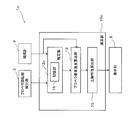
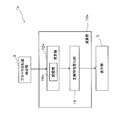
- FIG. 1 is a block diagram showing a configuration of a ship characteristic estimation apparatus 1 according to an embodiment of the present invention.
- the ship characteristic estimation device 1 includes a GPS signal reception unit 2, a propeller rotation speed detection unit 3, a tide meter 4, a calculation unit 10, and a display unit 5.
- the GPS signal receiving unit 2 is provided as a GNSS signal receiving unit for receiving a GPS signal as a navigation signal (GNSS signal) transmitted from a navigation satellite (not shown).
- the GPS signal receiving unit 2 is configured by, for example, a GPS antenna.
- the GPS signal received by the GPS signal receiving unit 2 (that is, the position information of the ship) is notified to the calculation unit 10 together with the time when the GPS signal is received.
- GNSS Global Navigation Satellite System
- GALILEO Global Navigation Satellite System
- GLONASS Global Navigation Satellite System
- the propeller rotational speed detection unit 3 is for detecting the rotational speed per unit time of the propeller for generating the thrust of the ship, and is constituted by a sensor capable of detecting the rotational speed, for example. The rotation speed detected by the propeller rotation speed detection unit 3 is notified to the calculation unit 10.
- the tide meter 4 is for measuring the flow velocity of the surface layer of seawater at the ship position, specifically, the surface flow velocity in the bow direction and the surface flow velocity in the starboard direction. Equipped to be exposed to.
- the tide meter 4 measures a surface current in a relatively shallow portion at the ship position.
- the bow direction surface flow velocity and starboard direction surface flow velocity measured by the tide meter 4 are notified to the arithmetic unit 10.
- the calculation unit 10 estimates the propeller propulsion speed at the ship position (target point) at each predetermined timing based on various information notified from the GPS signal reception unit 2, the propeller rotation number detection unit 3, and the tide meter 4. To do.
- the calculation unit 10 includes a ground speed calculation unit 11, an estimator 12, a propeller propulsion speed calculation unit 13, a coupling coefficient update unit 14, and a main engine characteristic calculation unit 15.
- the ground speed calculation unit 11 calculates the ground speed (ground speed vector) of the ship based on the position information of the ship notified from the GPS signal receiving unit 2 and the time when the ship position information is acquired. Specifically, the ground speed calculation unit 11 calculates the ground speed of the ship based on the ship position at at least two timings and the time when the position information of each ship position is acquired. The ground speed calculation unit 11 notifies the coupling coefficient update unit 14 of the ground speed calculated in this way.
- the estimator 12 is configured to estimate a speed (hereinafter referred to as a target speed) obtained by combining the propeller propulsion speed and the surface layer flow speed at the ship position.
- the estimator 12 includes the propeller rotation speed detected by the propeller rotation speed detection unit 3, the bow direction surface flow velocity and the starboard surface flow at the ship position measured by the tide meter.
- Speed is entered.
- the estimator 12 sets a value corresponding to a condition specified by a combination of these input values (a condition specified by a combination of a certain rotation speed, a certain bow direction surface flow velocity, and a certain starboard direction surface flow velocity),
- the target speed (target speed vector) is output to the propeller propulsion speed calculation unit 13.
- FIG. 2 is a diagram schematically illustrating an example of the configuration of the estimator 12.
- the estimator 12 is configured using a generally known neural network. Specifically, the estimator 12, a plurality of input units U IN_1 constituting the input layer, U IN_2, a U IN_3, a plurality of intermediate units U MID_1 constituting the hidden layer, U MID_2, a U MID_3, output layer Output units U OUT — 1 and U OUT — 2 are included.
- the configuration of the estimator 12 shown in FIG. 2 is merely an example, and the number of units in each layer and the number of hidden layers are not limited to those shown in FIG.
- the estimator 12 each of the input units U IN_1, U IN_2, when the input value U IN_3 (rotational speed of the propeller, etc.) is input, the coupling coefficient W I for those input values, M is multiplied , And output to the hidden layer intermediate units U MID — 1 , U MID — 2 and U MID — 3 .
- Each of the hidden layer intermediate units U MID — 1 , U MID — 2 and U MID — 3 sums the input values and multiplies the values based on the total values by the coupling coefficients W M, O to the output units U OUT — 1 and U OUT — 2 . Output.
- the output units U OUT — 1 and U OUT — 2 sum each input value and output a value based on the total value to the coupling coefficient update unit 14 as an output value.
- the value input to the estimator 12 does not necessarily have to be a parameter value itself such as a propeller rotational speed, but is a numerical value having a one-to-one relationship with those parameters (for example, proportional to the rotational speed). Or a voltage value that changes).
- each coupling coefficient W is updated by the coupling coefficient updating unit 14 as needed.
- each coupling coefficient W is coupled to the coupling coefficient updating unit 14 so that an error between the output value output from the estimator 12 and the surface layer flow velocity (teacher signal) measured by the tide meter 4 is reduced. Updated by.
- the output value output from the estimator 12 converges to the target speed every time the coupling coefficient W is updated, as will be described in detail later.
- the propeller propulsion speed calculation unit 13 calculates the propeller propulsion speed based on the output value as the target speed output from the estimator 12 and the surface layer flow speed measured by the tide meter 4. Specifically, the propeller propulsion speed calculation unit 13 calculates the propeller propulsion speed by subtracting the surface layer flow speed from the target speed.
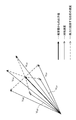
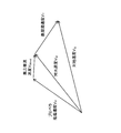
- FIG. 3 is a vector diagram showing a relationship among the target velocity vector V S , the propeller propulsion velocity vector VP, and the surface layer flow velocity vector V T.
- the target velocity vector V S is a vector obtained by synthesizing the propeller propulsion velocity vector VP and the surface flow velocity vector V T.
- the propelling speed calculating section 13 by subtracting the surface flow velocity vector V T from the target speed vector V S, the propeller propulsion velocity vector V P is calculated.
- the coupling coefficient update unit 14 sets the coupling coefficient W of the estimator 12 so that an error between the output value output from the estimator 12 and the ground speed (teacher signal) calculated by the ground speed calculation unit 11 is reduced. Update.
- the coupling coefficient updating unit 14 updates the coupling coefficient W by using back propagation (error back propagation method), for example.
- the main engine characteristic calculation unit 15 is for calculating characteristics of the main engine of the ship (a mechanism part for generating thrust in the ship).
- the main engine characteristic calculator 15 calculates the propeller propulsion speed with respect to the rotation speed of the propeller. Based on the propeller propulsion speed for each propeller rotation speed calculated by the propeller propulsion speed calculation section 13, the main engine characteristic calculation section 15 obtains the main engine characteristics by using, for example, regression analysis.
- FIG. 4 is a diagram illustrating an example of main machine characteristics displayed on the display unit 5.
- the main unit characteristics as shown by the solid line in FIG. 4 are displayed on the display unit 5.
- the main engine characteristics are ideal characteristics when a new boat is trialed or immediately after repair, and more specifically, characteristics such that the propeller propulsion speed with respect to the rotation speed of the propeller is increased (see the broken line in FIG. 4). . Therefore, for example, by comparing the main engine characteristics at the time of trial of a new boat with the main engine characteristics of the current ship, it is possible to infer the deterioration state of the engine, the fouling state of the hull surface, and the like. By knowing these states, the user can determine a more accurate operation plan, necessity of abnormality inspection, and the like.
- each coupling coefficient W stored in the estimator 12 has a coupling coefficient W so that an error between a value output from the estimator 12 and the ground speed as a teacher signal calculated from time to time becomes small. It is updated by the update unit 14.
- the ground speed in the case where the rotation speed of the propeller and the surface flow velocity are the same includes wind speed components of all magnitudes and directions. Therefore, when these are averaged, the wind speed components cancel each other, and the speed component obtained by synthesizing the propeller propulsion speed and the surface layer flow speed, that is, the target speed component remains. That is, when the coupling coefficient W of the estimator 12 is updated so that the error between the output value of the estimator 12 and the ground speed becomes small as described above, the influence of the wind speed component included in the ground speed gradually increases. Therefore, the output value of the estimator 12 converges to the target velocity component described above. Therefore, when the learning is sufficiently advanced (that is, when the coupling coefficient is updated a sufficient number of times), the output value from the estimator 12 can be estimated as the target speed.
- the propeller propulsion speed is based on the rotation speed of the propeller, the surface flow velocity measured by the tidal meter 4, and the target velocity estimated by the estimator 12. Is calculated. Thereby, the relationship between the rotation speed of the propeller and the water speed (propeller propulsion speed) of the ship at the rotation speed can be grasped relatively easily.
- the ship characteristic estimation apparatus 1 According to the ship characteristic estimation apparatus 1 according to the present embodiment, the relationship between the rotation speed of the propeller, which is a parameter affecting the water speed of the ship, and the water speed (propeller propulsion speed) of the ship corresponding thereto. Characteristics, that is, main engine characteristics can be easily grasped.
- the estimator 12 is configured using a neural network. Thereby, the estimator 12 capable of outputting the target speed can be appropriately configured.
- the estimator 12 is updated so that an error between the output value of the estimator 12 and the ground speed calculated by the ground speed calculation unit 11 is reduced. Thereby, the estimator 12 provided with the learning function can be configured. In addition, since the ship characteristic estimation device 1 can accumulate a large amount of data necessary for estimating an accurate target speed during navigation, learning data (ground speed data under certain conditions) is prepared in advance. Save time and effort.
- the ship characteristic estimation device 1 updates the coupling coefficient W stored in the estimator 12 so that an error between the output value of the estimator 12 and the ground speed calculated by the ground speed calculation unit 11 is reduced. ing. Thereby, the estimator 12 can be updated appropriately.
- the propeller propulsion speed is calculated by subtracting the surface layer flow speed from the target speed. Thereby, the propeller propulsion speed can be calculated more easily.
- the ground speed can be accurately calculated using GNSS which is widely spread, particularly GPS. Moreover, since a general ship is often equipped with a GPS antenna, the ground speed can be calculated without introducing a new device or the like.
- the propeller rotation speed and the surface flow velocity are detected by the propeller rotation speed detector 3 and the tide meter 4 mounted on the ship. Therefore, in the ship characteristic estimation apparatus 1, the propeller propulsion speed can be estimated using the propeller rotation speed detection unit 3 and the tide meter 4 that are widely used as general equipment.
- FIG. 6 is a block diagram showing a configuration of a ship characteristic estimation device 1a according to a modification.
- the ship characteristic estimation apparatus 1a according to the present modification has a configuration in which the coupling coefficient update unit 14 is omitted. That is, the ship characteristic estimation device 1a according to the present modification does not have a learning function. Further, in the ship characteristic estimation device 1a according to this modification, the GPS signal reception unit 2 and the ground speed calculation unit 11 are also omitted.
- the output as the target speed is obtained by the estimator 12a in which the coupling coefficient W is determined based on a lot of previously acquired learning data (data on the ground speed at a certain condition). The value is output. Even with such a configuration, the propeller propulsion speed can be easily calculated as in the case of the above embodiment.
- FIG. 7 is a block diagram showing a configuration of the ship characteristic estimation apparatus 1b according to the modification.
- the ship characteristic estimation device 1b according to this modification is greatly different in the configuration of the estimator 12b from the ship characteristic estimation device 1 according to the above embodiment.
- the estimator 12b is not configured using a neural network, but includes a storage unit 16 and an update unit 17.
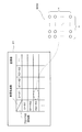
- FIG. 8 is a diagram for explaining the estimator 12b shown in FIG. 7 in detail.
- the storage unit 16 stores a matrix table.
- each condition (corresponding to each cell in the table) specified by a combination of each value (X1, X2, X3,...) Of the surface flow velocity and each value (R1, R2, R3,. )
- the ground speed calculated at the time of) is stored.
- one ground speed value is indicated by one circle. That is, the storage unit 16 stores, for example, five ground speed values calculated when the surface flow velocity is X1 and the rotation speed is R1.
- the estimator 12b When the rotational speed (for example, R2) detected by the propeller rotational speed detection unit 3 and the surface flow velocity (for example, X3) measured by the tide meter 4 are input to the estimator 12b, the estimator 12b An average value of the ground speeds (11 in the case of FIG. 8) included in the cell having the rotation speed R2 and the surface layer flow speed X3 is calculated. Then, the estimator 12b outputs the average value as an output value.
- the target speed can be appropriately estimated also by the estimator 12b according to this modification.
- the updating unit 17 updates the table stored in the storage unit 16 using the ground speed calculated at the timing when the rotational speed and the surface flow velocity input to the estimator 12b are detected. Specifically, the ground speed calculated for a predetermined rotation speed (for example, R3) and a predetermined surface layer flow speed (for example, X2) is added to the cell specified by R3 and X2. By performing this operation as needed, learning data is accumulated even during navigation, and the target speed can be estimated more accurately. That is, the estimator 12b according to this modification also has a learning function. As a result, the propeller propulsion speed can be calculated more accurately.
- a predetermined rotation speed for example, R3
- a predetermined surface layer flow speed for example, X2
- the ship characteristic estimation apparatus 1c which does not have a learning function can be comprised by setting it as the structure which abbreviate
- FIG. 10 is a block diagram showing a configuration of a ship characteristic estimation device 1d according to a modification.
- the ship characteristic estimation device 1d according to the present modification further includes a learning coefficient setting processing unit 20.
- the estimator 12d is configured using a neural network as in the case of the above embodiment, and is configured so that the coupling coefficient is updated as needed by so-called supervised learning.
- an error between the output value from the estimator 12d and the teacher signal (ground speed) is calculated.
- the ship characteristic estimation device 1d updates the coupling coefficient W while propagating the error as a learning signal from the unit on the output layer side to the unit on the input layer side.
- the correction amount of the coupling coefficient is given by the following equation (1).
- ⁇ W i, j n, n ⁇ 1 (t) is a correction amount for the weight of the coupling between the unit j of the n ⁇ 1 layer and the unit i of the n layer
- ⁇ is a learning coefficient
- ⁇ i n is a learning signal returned from the unit i of the nth layer to each unit of the n ⁇ 1 layer
- X j n ⁇ 1 is an output value of the unit j of the n ⁇ 1 layer
- ⁇ is a stabilization coefficient
- ⁇ W i, j n , n-1 (t-1) indicates the previous correction amount.
- the n-1th layer is one layer on the input side than the nth layer.
- FIG. 11 is a block diagram illustrating a configuration of the learning coefficient setting processing unit 20.
- the learning coefficient setting processing unit 20 is for setting the learning coefficient in Expression (1) as needed.
- the learning coefficient setting processing unit 20 includes a storage unit 21, an SOM update unit 22, a count unit 23, a learning coefficient calculation unit 24, and a learning coefficient setting unit 25. .
- FIG. 12 is a diagram schematically showing a table stored in the storage unit 21 and a self-organizing map SOM stored corresponding to each cell of the table.
- the storage unit 21 stores a table cut in a mesh shape for each predetermined propeller rotational speed and for each predetermined surface layer flow velocity.
- a corresponding self-organizing map SOM is stored in each cell of this table.
- Each self-organizing map SOM of this modification is a two-dimensional SOM composed of n ⁇ n units.
- Each unit stores a reference vector having the same dimension as the input vector. In an initial state (a state in which learning is not performed), an appropriate reference vector is set for each unit.
- the SOM update unit 22 updates the SOM according to an input vector (a vector composed of a propeller rotation speed, a surface flow velocity, a ground velocity, etc., input at every predetermined timing). Specifically, the SOM update unit 22 updates the SOM stored in the cell including the input rotation speed and surface flow velocity as follows.
- the SOM update unit 22 sets the unit having the shortest Euclidean distance from the input vector as the winner unit, the reference vector stored in the winner unit, and the reference vector stored in units around the winner unit. Is updated based on the following equation (2).
- m i is a reference vector
- x (t) is an input vector
- h i is a neighborhood function represented by c ⁇ exp ( ⁇ dis 2 / ⁇ 2 ).
- c is a learning rate coefficient
- dis
- mc is a reference vector that minimizes the Euclidean distance from x (t).
- the SOM update unit 22 updates the self-organizing map SOM at any time using the above-described equation (2) according to the input vector input at any time.
- the counting unit 23 counts the number of units having a reference vector whose difference from the input vector (Euclidean distance) is a threshold value or less.
- the learning coefficient calculation unit 24 takes the reciprocal of the value counted by the counting unit 23 and calculates the value as a learning coefficient. That is, the learning coefficient is small when the count value is large (when there are many similar input data), and the learning coefficient is large when the count value is small (when there are few similar input data).
- the learning coefficient setting unit 25 notifies the estimator 12d of the value calculated by the learning coefficient calculation unit 24, and sets it as the learning coefficient ⁇ in the equation (1).
- the estimator 12d uses the learning coefficient ⁇ to update the coupling coefficient based on the equation (1), and then calculates a water velocity vector based on the updated coupling coefficient.
- the learning coefficient becomes small.
- the correction amount ⁇ W i, j n, n ⁇ 1 (t) of the coupling coefficient becomes small.
- the correction amount of the coupling coefficient becomes large.
- FIG. 13 is a block diagram illustrating a configuration of the learning coefficient setting processing unit 40 of the ship characteristic estimation device according to the modification.
- the learning coefficient setting processing unit 40 according to the present modification has a learning coefficient ⁇ of Expression (1) used in an estimator configured using a neural network. Is for setting.
- the learning coefficient setting processing unit 40 according to the present modification is different in configuration from the learning coefficient setting processing unit 20 of the above-described modification.
- the learning coefficient setting processing unit 40 according to the present modification includes a storage unit 41, a learning coefficient calculation unit 42, and a learning coefficient setting unit 43.
- FIG. 14 is a diagram showing a table stored in the storage unit 41 and learning data stored corresponding to each cell (each area) of the table.
- the storage unit 41 stores a table cut in a mesh shape for each predetermined propeller rotational speed and for each predetermined surface layer flow velocity, as in the case of the above-described modification.
- the learning data stored in each area is mapped according to the ground speed of each learning data.
- each learning data is It is mapped according to the speed.
- the learning coefficient calculation unit 42 calculates the number of learning data (4 in the case of FIG. 14) stored in the sub-area including the most recently input learning data among all the sub-areas including the sub-area. A value obtained by normalizing the reciprocal of the value divided by the number of learning data stored in the subarea with the largest number of learning data (10 in subarea A in the case of FIG. 14) is set as the learning coefficient. Then, the learning coefficient setting unit 43 notifies the estimator of the learning coefficient set by the learning coefficient calculation unit 42 as in the learning coefficient setting unit 25 of the above modification, and sets it as the learning coefficient ⁇ in the equation (1). . Even with such a configuration, the learning coefficient can be set appropriately.
- FIG. 15 is a block diagram showing a configuration of the ship characteristic estimation device 1e according to the modification.
- the GPS signal receiving unit 2 and the like constituting a part of the ship characteristic estimation device 1e and the calculation unit 10e are mounted at different places.
- the GPS signal receiving unit 2, the propeller rotation number detecting unit 3, and the tide meter 4 are mounted on the own ship, and the calculation unit 10e is installed in, for example, a land center. 30.
- the ship characteristic estimation apparatus 1e which concerns on this modification is provided with the transmission part 19a and the receiving part 19b which were mounted in the own ship.
- the transmission unit 19a transmits various data detected by the GPS signal reception unit 2, the propeller rotation number detection unit 3, and the tide meter 4 to the data center 30 via the antenna.
- the calculation unit 10h of the data center 30 calculates the propeller propulsion speed based on the various data, as in the case of the above embodiment.
- the calculation unit 10 e calculates the propeller propulsion speed and stores them in the database unit 31.
- the receiving unit 19b receives the propeller propulsion speed stored in the database unit 31. This data is displayed on the display unit 5.
- a calculation unit having a relatively large calculation load can be provided in a place different from the own ship. Thereby, even if it does not mount a calculating part in own ship, the surface layer flow velocity in the own ship position can be estimated.
- the learning data can be supplemented when the learning data is not sufficiently accumulated.
- FIG. 16 is a schematic diagram for explaining complementation of learning data.
- a surface flow from 45 degrees on the port side and a surface flow from 45 degrees on the starboard side (the magnitude of the surface flow) Is the same as each other)
- the traveling direction is expected to be symmetrical.
- propeller speed predetermined rotational speed, orientation port rear 45 degree surface current when the surface layer flow speed is a predetermined magnitude, the ground speed is met V G
- the data can be supplemented as follows based on the learning data.
- the size of the propeller speed and surface velocity is the same as the learning data, orientation starboard rear 45 degree surface current, as learning data when the, vector V 'G obtained by mirror-inverting Can be complemented.
- the propeller propulsion speed can be accurately estimated even in the initial stage where the learning data is not sufficiently accumulated, for example.
- the surface layer flow velocity is measured using the tide meter 4, but the present invention is not limited to this, and it may be estimated by a surface layer flow estimation device or the like having a mechanism different from that of the tide meter 4.
- the main unit characteristic graph is displayed on the display unit 5 to notify the user of the current state of the main unit, but the present invention is not limited to this. Specifically, an indicator indicating the deterioration state of the main engine can be displayed on the display unit.
- FIG. 17 is a diagram illustrating an example of the tachometer 6 displayed on the display unit.
- the tachometer 6 is provided with a scale portion 6a on which a numerical value of the rotation speed is written, and the indicator needle 6b is configured to indicate the rotation speed of the propeller.
- the color of the indicator needle 6b functions as an index indicating the deterioration state of the main machine. Specifically, in a state where the main engine characteristics have not deteriorated, the color of the indicating needle 6b is displayed in, for example, blue (no hatching) as shown in FIG. In the state where the main engine characteristics are slightly deteriorated, the color of the indicating needle 6b is displayed, for example, in yellow (hatching with a wide interval) as shown in FIG. When the main machine characteristics are greatly deteriorated and repair is necessary, the color of the indicator needle 6b is displayed in, for example, red (hatching with a narrow interval) as shown in FIG. As a result, the user can easily visually recognize the deterioration of the main engine characteristics.
- the deterioration state of the main engine characteristics described above is, for example, a ratio between the propeller propulsion speed at the predetermined speed of the main engine at the time of the predetermined speed of the main engine at the time of the predetermined speed of the main engine at the time of trial of a new boat or immediately after repair. Can be determined based on
- the index indicating the deterioration state of the main engine is not limited to the color as described above.
- a pattern corresponding to the deterioration state can be used, or the brightness of the tachometer 6 is gradually increased according to the deterioration state. It can also be darkened.
- the color of the indicator needle 6b is changed according to the deterioration state of the main machine.
- the present invention is not limited to this.
- the color may be changed according to the deterioration state of the main engine.
- any character such as an announcement indicating the deterioration state may be used.
- FIG. 18 is a block diagram showing a configuration of a ship characteristic estimation device 1f according to a modification.
- the propeller propulsion speed and the main engine characteristics are calculated as the ship characteristics.
- the wind power propulsion speed (the speed of water against the ship due to the wind force with respect to the ship) as the characteristics of the ship.
- the ship characteristic estimation device 1 f according to the present modification includes a GPS signal receiving unit 2, a propeller rotational speed detection unit 3, a tide meter 4, a calculation unit 10 f, and a display unit 5. I have.
- the GPS signal receiver 2, the propeller rotation speed detector 3, and the tide meter 4 have the same configuration as in the above embodiment, and operate in the same manner as in the above embodiment.
- the calculation unit 10f includes a ground speed calculation unit 11, an estimator 12, a wind propulsion speed calculation unit 26, a coupling coefficient update unit 14, and a wind power characteristic calculation unit 27.
- the ground speed calculation unit 11, the estimator 12, and the coupling coefficient update unit 14 have the same configuration as in the above embodiment, and operate in the same manner as in the above embodiment.
- the wind power propulsion speed calculation unit 26 calculates the wind power propulsion speed that is the water speed of the own ship due to the wind power of the ship.
- the wind power propulsion speed calculator 26 calculates the wind power propulsion speed based on the output value as the target speed output from the estimator 12 and the ground speed calculated by the ground speed calculator. Specifically, the wind propulsion speed calculation unit 26 calculates the wind propulsion speed by subtracting the target speed (the output value from the estimator 12) from the ground speed.
- the ground speed V G is a vector obtained by synthesizing the target speed V S and the wind propulsion speed V Wind . Accordingly, the wind power propulsion speed calculation unit 26 subtracts the target speed V S from the ground speed V G as described above, thereby calculating the wind power propulsion speed V Wind .
- the wind power characteristic calculation unit 27 is for calculating at what speed the ship moves by the wind power of the ship. In the present embodiment, the wind power characteristic calculation unit 27 calculates the wind propulsion speed with respect to the direction and magnitude of the wind force.
- FIG. 19 is a diagram illustrating an example of wind power characteristics displayed on the display unit 5.
- wind characteristics as shown in FIG. 19 are displayed on the display unit 5, for example.
- the moving speed of the ship that is, the wind propulsion speed
- the user can know how much the own ship is made to flow (moves) at what wind direction and wind speed. Then, for example, the user can estimate the future route more appropriately as an example.
- each modification demonstrated as a modification in the ship characteristic estimation apparatus 1 which concerns on the said embodiment can be applied suitably to this modification.
- FIG. 20 is a block diagram showing a configuration of a ship characteristic estimation apparatus 1g according to a modification.
- the main engine characteristic or the wind power characteristic is calculated as the ship characteristic.
- both the main engine characteristics and the wind power characteristics can be calculated.
- FIG. 21 is a diagram illustrating an example of a display example of the display unit 5 of the ship characteristic estimation device 1g according to the present modification.
- the range of the ship position after a predetermined time has elapsed based on the main engine characteristic calculated by the main engine characteristic calculation unit 15 and the wind power characteristic calculated by the wind power characteristic calculation unit 27.
- FIG. 21 shows the range of the ship position when the rotation speed of the main engine is maintained at a predetermined rotation speed.
- the range indicated by the solid line in FIG. 21 is the case where the main engine continues navigating at a predetermined rotational speed, and the maximum wind speed V 3 [m / s] continues to blow.
- the range in which the ship can exist is shown. Thereby, the user can predict the range in which the ship can exist after a predetermined time has elapsed.
- the position range can be predicted based on the rotation number. Furthermore, in this modification, it is also possible to perform more accurate position prediction by taking into account the surface layer flow velocity.
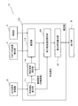
- FIG. 22 is a block diagram showing a configuration of a ship characteristic estimation device 1h according to a modification.
- the ship characteristic estimation device 1h according to this modification example calculates the propeller propulsion speed and the main engine characteristic as in the ship characteristic estimation apparatus according to the above-described embodiment and each modification example, but the calculation method is different.
- the ship characteristic estimation device 1 h includes a propeller rotation speed detection unit 3, a hydrometer 7, an estimator 12 h, a coupling coefficient update unit 14, and a main engine characteristic calculation unit. 15. Since the propeller rotational speed detection unit 3 operates in the same manner as in the above embodiment, a detailed description thereof is omitted.
- the water speed meter 7 is for measuring the water speed near the ship and is mounted on the ship.
- an acoustic water velocimeter can be cited as an example.
- FIG. 23 is a diagram schematically illustrating an example of the configuration of the estimator 12h.
- the estimator 12h is configured using a neural network as in the case of the above-described embodiment (see FIG. 2).
- one input unit U IN_1 to which the rotation speed of the propeller is input is provided.
- the configuration of the estimator 12h is merely an example, and the number of units in each layer and the number of hidden layers are not limited to those illustrated in FIG.
- each coupling coefficient W is updated by the coupling coefficient updating unit 14 as needed. Specifically, each coupling coefficient W is updated so that an error between the output value output from the estimator 12h and the water velocity (teacher signal) measured by the water velocity meter 7 is reduced. Updated by the unit 14.
- the coupling coefficient update unit 14 reduces the error between the output value output from the estimator 12h and the water speed (teacher signal) measured by the water speed meter 7 so that the coupling coefficient W of the estimator 12h is reduced. Update.
- the coupling coefficient updating unit 14 updates the coupling coefficient W by using back propagation (error back propagation method), for example.
- the main machine characteristic calculation unit 15 operates in the same manner as in the above embodiment, thereby calculating the main machine characteristic shown in FIG. 4 as an example.
- FIG. 24 is a diagram for explaining the reason why the output value output from the estimator 12h converges to the propeller propulsion speed every time the coupling coefficient W of the estimator 12 is updated. As described above, each coupling coefficient W stored in the estimator 12h is combined so that an error between a value output from the estimator 12h at any time and a water speed as a teacher signal measured at any time is small. Updated by the coefficient updating unit 14.
- the wind speed is different in size and direction due to the sea area, time, weather conditions, and the like. Therefore, it is considered that the wind speed component of any magnitude and direction is included in the water speed when the rotation speed of the propeller is the same. Therefore, when these are averaged, the wind speed components cancel each other, and the propeller propulsion speed remains. That is, when the coupling coefficient W of the estimator 12h is updated so as to reduce the error between the output value of the estimator 12h and the water speed, as described above, the influence of the wind speed component included in the water speed. Is gradually reduced, the output value of the estimator 12h converges to the propeller propulsion speed. Therefore, when the learning is sufficiently advanced (that is, when the coupling coefficient is updated a sufficient number of times), the output value from the estimator 12h can be estimated as the target speed.
- the propeller propulsion speed is calculated based on the rotation speed of the propeller and the water speed.
- the relationship between the rotation speed of the propeller and the water speed (propeller propulsion speed) of the ship at the rotation speed can be grasped relatively easily.
- the number of parameters required for estimating the propeller propulsion speed is smaller than in the case of the above-described embodiment, so that the main engine characteristic can be obtained more easily. be able to.
- the estimator 12h is configured using a neural network. Thereby, the estimator 12h that can output the propeller propulsion speed can be appropriately configured.
- the estimator 12h is updated so that the error between the output value of the estimator 12h and the water speed is reduced.
- the estimator 12h provided with the learning function can be configured.
- the ship characteristic estimation device 1h can accumulate a large amount of data necessary for estimating an accurate propeller propulsion speed during navigation, learning data (ground speed data under certain conditions) is prepared in advance. This saves you time and effort.
- the coupling coefficient W stored in the estimator 12h is updated so that the error between the output value of the estimator 12h and the water velocity is reduced. Thereby, the estimator 12h can be updated appropriately.
- the learning coefficient setting processing unit described with reference to FIGS. 10 to 14 may be provided in the ship characteristic estimation device 1h according to the present modification. Accordingly, an appropriate learning coefficient can be set as in the modification described with reference to FIGS. 10 to 14.
- FIG. 25 is a block diagram showing a configuration of the ship characteristic estimation apparatus 1i according to the modification.
- the ship characteristic estimation apparatus 1i according to the present modification has a configuration in which the coupling coefficient update unit 14 is omitted. That is, the ship characteristic estimation device 1i according to this modification does not have a learning function.
- the ship characteristic estimation apparatus 1i which concerns on this modification becomes a structure by which the water speedometer 7 was also abbreviate
- the propeller is determined by the estimator 12i in which the coupling coefficient W is determined based on a large amount of learning data acquired in advance (water speed data at each rotation speed). An output value as a propulsion speed is output. Even with such a configuration, the propeller propulsion speed can be easily calculated as in the case of the above embodiment.
- FIG. 26 is a block diagram showing a configuration of a ship characteristic estimation apparatus 1j according to a modification.
- the ship characteristic estimation device 1j according to the present modification is greatly different from the ship characteristic estimation device 1h shown in FIG. 22 in the configuration of the estimator 12j.
- the estimator 12j is not configured using a neural network, but includes a storage unit 16j and an update unit 17j.
- FIG. 27 is a diagram for explaining the estimator 12j shown in FIG. 26 in detail.
- the storage unit 16j As shown in FIG. 27, a plurality of water speeds measured at the time of detecting the detected number of revolutions are stored for each corresponding number of revolutions (in the case of FIG. 27, R1, R2, R3, ... everything).
- one water speed value is indicated by one circle. That is, the storage unit 16j stores, for example, five water speed values calculated when the rotation speed is R1.
- the estimator 12j measures the water speed (10 in the case of FIG. 27) corresponding to the rotational speed R2. The average value of is calculated. Then, the estimator 12j outputs the average value as an output value.
- the propeller propulsion speed can be appropriately estimated also by the estimator 12j according to this modification.
- the update unit 17j updates the table stored in the storage unit 16j using the water speed calculated at the timing when the rotation speed input to the estimator 12j is detected. Specifically, the water speed calculated at a predetermined rotation speed (for example, R3) is added to the cell specified by R3. By performing this operation as needed, learning data is accumulated even during navigation, and the target speed can be estimated more accurately. That is, the estimator 12j according to this modification also has a learning function. As a result, the propeller propulsion speed can be estimated more accurately.
- a predetermined rotation speed for example, R3
- the ship characteristic estimation apparatus 1k which does not have a learning function can be comprised (refer FIG. 28). In this case, it is necessary to store a plurality of learning data obtained in advance (data corresponding to one circle in FIG. 27) in the storage unit 16k.
- FIG. 29 is a block diagram showing a configuration of a ship characteristic estimation apparatus 1l according to a modification.
- the ship characteristic estimation device 11 according to the present modification has a configuration in which a wind propulsion speed calculation unit 26a and a wind characteristic calculation unit 27 are added to the ship characteristic estimation device 1h according to the modification described with reference to FIG. Yes.
- a wind force characteristic can also be calculated.
- FIG. 30 is a vector diagram showing a relationship among the water speed V W , the propeller propulsion speed V p, and the wind power propulsion speed V Wind .
- the wind power propulsion speed calculation unit 26a calculates the wind power propulsion speed V Wind based on the output value output from the estimator 12l (that is, the propeller propulsion speed V p ) and the water speed measured by the water speed meter 7. calculate. Specifically, the wind power propulsion speed calculation unit 26a calculates the wind power propulsion speed by subtracting the propeller propulsion speed from the water speed.
- the wind power characteristic calculation unit 27 operates in the same manner as the wind power characteristic calculation unit 27 according to the modification described with reference to FIG. 18. For example, the wind power characteristic calculation unit 27 displays the wind power characteristics as illustrated in FIG. 19 on the display unit 5.
- wind power characteristics can be easily calculated as in the modification described with reference to FIG. Moreover, according to the ship characteristic estimation device 11 according to the present modification, the number of parameters required for estimating the wind power propulsion speed is smaller than in the case shown in FIG. Can do.
- FIG. 31 is a block diagram showing the configuration of the water speed calculation unit for calculating the water speed.
- the water speed meter 7 is used to calculate the water speed.
- the present invention is not limited to this.
- the water velocity calculation unit 8 may be used.
- the ground speed calculated by the ground speed calculator 11 and the surface current measured by the tide meter 4 are input to the water speed calculator 8. Then, the water speed calculation unit 8 calculates the water speed by subtracting the surface layer flow speed from the ground speed. Thereby, the water velocity can be calculated appropriately.
Landscapes
- Engineering & Computer Science (AREA)
- Chemical & Material Sciences (AREA)
- Combustion & Propulsion (AREA)
- Mechanical Engineering (AREA)
- Ocean & Marine Engineering (AREA)
- Physics & Mathematics (AREA)
- Fluid Mechanics (AREA)
- General Engineering & Computer Science (AREA)
- Theoretical Computer Science (AREA)
- Testing Or Calibration Of Command Recording Devices (AREA)
- Traffic Control Systems (AREA)
Abstract
【課題】船舶の対水速度に影響を与えるパラメータの値と、該パラメータに起因する船舶の対水速度との関係性を、容易に把握する。 【解決手段】表層流速度ベクトル及び船舶のプロペラの回転数を受け付けるとともに、受け付けられた表層流速度ベクトルの値及び回転数の値の組み合わせにより特定される各条件に対応する値を、プロペラの回転に起因する船舶の速度ベクトルであるプロペラ推進速度ベクトルと表層流速度ベクトルとが合成された対象速度ベクトル、と推定して出力する推定器12aと、推定器12aの出力値と表層流速度ベクトルとに基づき、プロペラ推進速度ベクトルを算出するプロペラ推進速度算出部13と、を備えた船舶特性推定装置1aを構成する。
Description
本発明は、船舶の特性を推定する船舶特性推定装置に関する。
従来より、船舶の状態(経時的に変化する船舶の特性)を正確に把握するための様々な試みがなされている。例えば、特許文献1には、船舶に取り付けられた各種センサによって検出された運転情報(船舶の主機の温度、圧力、回転数等)に基づいて、船舶の状態を診断可能なシステムが開示されている。
ところで、船舶の状態を把握するにあたり、船舶の対水速度(水に対する船舶の速度)に影響を与えるパラメータの値と、各値に対応する実際の船舶の対水速度との関係を把握することは、非常に重要である。この関係性を把握することで、例えば一例として、船舶の航行計画をより正確に立てることができるようになる。しかし、上述した特許文献には、このことについては何ら記載されていない。
例えば、船舶の対水速度に影響を与えるパラメータとして、船舶のプロペラの回転数、及び船舶に対する風力、が挙げられる。そして、ある船舶において、プロペラの回転数と、該回転数に起因する船舶の対水速度との関係性を把握しようとすると、船舶の対水速度に影響を与える他のパラメータ(風力等)を一定に保った状態で実験を行う必要があり、非常に手間がかかる。これは、船舶に対する風力と、該風力に起因する船舶の対水速度との関係性を把握する場合も、同様である。
本発明は、上記課題を解決するためのものであり、その目的は、船舶の対水速度に影響を与えるパラメータの値と、該パラメータに起因する船舶の対水速度との関係性を、容易に把握することである。
(1)上記課題を解決するために、この発明のある局面に係る船舶特性推定装置は、航行する船舶が位置する対象地点における表層流の速度ベクトルである表層流速度ベクトル、及び、前記対象地点における前記船舶のプロペラの回転数の入力を受け付けるとともに、受け付けられた前記表層流速度ベクトルの値及び前記回転数の値の組み合わせにより特定される各条件に対応する値を、前記プロペラの回転に起因する前記船舶の速度ベクトルであるプロペラ推進速度ベクトルと前記表層流速度ベクトルとが合成された対象速度ベクトル、と推定して出力する推定器と、前記推定器で推定された前記対象速度ベクトルとしての出力値と、前記表層流速度ベクトルとに基づき、前記プロペラ推進速度ベクトルを算出するプロペラ推進速度算出部と、を備えている。
(2)好ましくは、前記プロペラ推進速度算出部は、前記推定器から出力された前記出力値から、前記表層流速度ベクトルを減算することにより、前記プロペラ推進速度ベクトルを算出する。
(3)上記課題を解決するために、この発明のある局面に係る船舶特性推定装置は、航行する船舶が位置する対象地点における該船舶の対地速度ベクトルを算出する対地速度算出部と、前記対象地点における表層流の速度ベクトルである表層流速度ベクトル、及び、前記対象地点における前記船舶のプロペラの回転数の入力を受け付けるとともに、受け付けられた前記表層流速度ベクトルの値及び前記回転数の値の組み合わせにより特定される各条件に対応する値を、前記プロペラの回転に起因する前記船舶の速度ベクトルであるプロペラ推進速度ベクトルと前記表層流速度ベクトルとが合成された対象速度ベクトル、と推定して出力する推定器と、前記推定器で推定された前記対象速度ベクトルとしての出力値と、前記対地速度算出部で算出された前記対地速度ベクトルとに基づき、前記対象地点における前記船舶に対する風力に起因する前記船舶の速度ベクトルである風力推進速度ベクトルを算出する風力推進速度算出部と、を備えている。
なお、対地速度とは、地面に対する速度である。
(4)好ましくは、前記風力推進速度算出部は、前記対地速度ベクトルから、前記推定器から出力された前記出力値を減算することにより、前記風力推進速度ベクトルを算出する。
(5)好ましくは、前記推定器は、ニューラルネットワークを用いて構成されている。
(6)好ましくは、前記船舶特性推定装置は、前記船舶の対地速度ベクトルを算出する対地速度算出部を更に備え、前記推定器は、前記各条件に対応する複数の前記対地速度ベクトルの平均値を前記出力値として出力するように、構成されている。
(7)好ましくは、前記船舶特性推定装置は、前記船舶の対地速度ベクトルを算出する対地速度算出部と、前記推定器からの前記出力値と、前記対地速度ベクトルで算出された前記対地速度ベクトルとを比較するとともに、該出力値と該対地速度ベクトルとの誤差が少なくなるように、前記推定器を更新する更新部と、を更に備えている。
(8)更に好ましくは、前記推定器は、ニューラルネットワークを用いて構成され、それぞれに、前記表層流速度ベクトルに関する情報及び前記回転数のいずれかが入力される複数の入力ユニットと、前記対象速度ベクトルとしての前記出力値を出力する出力ユニットとを有し、前記ニューラルネットワークにおける入力側のユニットから出力される値には、結合係数が乗算された後、出力側のユニットに伝送され、前記更新部は、前記出力値と、教師信号としての前記対地速度ベクトルとを比較するとともに、該出力値と該教師信号との誤差が少なくなるように、前記結合係数を更新する。
(9)好ましくは、前記船舶特性推定装置は、前記船舶の対地速度ベクトルを算出する対地速度算出部と、前記船舶に搭載され、GNSS信号を受信するGNSS信号受信部と、を更に備え、前記対地速度算出部は、前記GNSS信号受信部で受信されたGNSS信号、及び該GNSS信号が受信された時刻に基づき、前記対地速度ベクトルを算出する。
(10)好ましくは、前記船舶特性推定装置は、前記回転数を検出するプロペラ回転数検出部と、前記表層流速度ベクトルを計測する潮流計と、を更に備え、前記推定器には、前記プロペラ回転数検出部で検出された前記回転数と、前記潮流計で計測された前記表層流速度ベクトルと、が入力される。
(11)上記課題を解決するために、この発明のある局面に係る船舶特性推定装置は、航行する船舶が位置する対象地点における前記船舶のプロペラの回転数を受け付けるとともに、受け付けられた前記回転数の各値に対応する値を、前記プロペラの回転に起因する
前記船舶の速度ベクトルであるプロペラ推進速度ベクトル、と推定して出力する推定器、を備えている。
前記船舶の速度ベクトルであるプロペラ推進速度ベクトル、と推定して出力する推定器、を備えている。
(12)好ましくは、前記推定器は、ニューラルネットワークを用いて構成されている。
(13)好ましくは、前記船舶特性推定装置は、前記船舶の対水速度ベクトルを算出する対水速度算出部を更に備え、前記推定器は、前記回転数の検出時における複数の前記対水速度ベクトルであって、前記回転数の各値に対応する複数の前記対水速度ベクトル、の平均値を、前記プロペラ推進速度ベクトルとして出力するように、構成されている。
(14)好ましくは、前記船舶特性推定装置は、前記船舶の対水速度ベクトルを算出する対水速度算出部と、前記推定器からの出力値と、前記対水速度算出部で算出された前記対水速度ベクトルとを比較するとともに、該出力値と該対水速度ベクトルとの誤差が少なくなるように、前記推定器を更新する更新部と、を更に備えている。
(15)更に好ましくは、前記推定器は、ニューラルネットワークを用いて構成され、前記回転数が入力される入力ユニットと、前記出力値を出力する出力ユニットとを有し、前記ニューラルネットワークにおける入力側のユニットから出力される値には、結合係数が乗算された後、出力側のユニットに伝送され、前記更新部は、前記出力値と、教師信号としての前記対水速度ベクトルとを比較するとともに、該出力値と該教師信号との誤差が少なくなるように、前記結合係数を更新する。
(16)好ましくは、前記船舶特性推定装置は、前記推定器から出力された出力値と、前記対象地点における前記船舶の対水速度ベクトルとに基づき、前記対象地点における前記船舶に対する風力に起因する前記船舶の速度ベクトルである風力推進速度ベクトル、を算出する風力推進速度算出部、を更に備えている。
(17)更に好ましくは、前記風力推進速度算出部は、前記対水速度ベクトルから、前記推定器から出力された前記出力値を減算することにより、前記風力推進速度ベクトルを算出する。
本発明によれば、船舶の対水速度に影響を与えるパラメータの値と、該パラメータに起因する船舶の対水速度との関係性を、容易に把握できる。
本発明の実施形態に係る船舶特性推定装置1ついて、図を参照して説明する。本発明の実施形態に係る船舶特性推定装置1は、自船(船舶)に搭載されている。船舶特性推定装置1は、船舶の対水速度のうち、該船舶のプロペラの回転に起因する速度を推定する。船舶特性推定装置1では、所定のタイミング毎に所定のパラメータ(本実施形態では、自船のプロペラの回転数、船首方向表層流速度、及び右舷方向表層流速度)が自動で求められるとともに、各パラメータの値の組み合わせにより特定される条件毎に、自船のプロペラの回転に起因する速度が算出される。
なお、以下では、船舶の対水速度のうち、該船舶のプロペラの回転に起因する速度を、プロペラ推進速度と称する。
[全体構成]
図1は、本発明の実施形態に係る船舶特性推定装置1の構成を示すブロック図である。船舶特性推定装置1は、図1に示すように、GPS信号受信部2と、プロペラ回転数検出部3と、潮流計4と、演算部10と、表示部5と、を備えている。
図1は、本発明の実施形態に係る船舶特性推定装置1の構成を示すブロック図である。船舶特性推定装置1は、図1に示すように、GPS信号受信部2と、プロペラ回転数検出部3と、潮流計4と、演算部10と、表示部5と、を備えている。
GPS信号受信部2は、航法衛星(図示省略)から送信される航法信号(GNSS信号)としてのGPS信号を受信するための、GNSS信号受信部として設けられている。GPS信号受信部2は、例えば、GPSアンテナによって構成されている。GPS信号受信部2で受信されたGPS信号(すなわち、自船の位置情報)は、該GPS信号が受信された時刻とともに、演算部10に通知される。
なお、本実施形態では、GNSS信号受信部としてGPS信号受信部2を用いているが、これに限らず、その他のGNSSシステムにおいて用いられる受信部を用いてもよい。ここで、GNSSとは、全地球航法衛星システム(GNSS;Global Navigation Satellite Systems)の略語である。このGNSSは、米国により運営される「GPS」、欧州により運営される「GALILEO」及びロシアにより運営される「GLONASS」等の総称である。
プロペラ回転数検出部3は、自船の推力を発生させるためのプロペラの単位時間当たりの回転数を検出するためのものであって、例えば、回転数を検出可能なセンサによって構成されている。プロペラ回転数検出部3で検出された回転数は、演算部10に通知される。
潮流計4は、自船位置における海水の表層部分の流速、具体的には、船首方向表層流速度、及び右舷方向表層流速度を計測するためのものであって、例えば自船の船底において水中に露出するように装備される。潮流計4では、自船位置における比較的浅い部分の表層流が計測される。潮流計4で計測された船首方向表層流速度及び右舷方向表層流速度は、演算部10に通知される。
演算部10は、GPS信号受信部2、プロペラ回転数検出部3、及び潮流計4から通知された各種情報に基づき、所定のタイミング毎に、自船位置(対象地点)におけるプロペラ推進速度を推定する。演算部10は、対地速度算出部11と、推定器12と、プロペラ推進速度算出部13と、結合係数更新部14と、主機特性算出部15を備えている。
対地速度算出部11は、GPS信号受信部2から通知される自船の位置情報、及びその自船位置情報が取得された時刻に基づき、自船の対地速度(対地速度ベクトル)を算出する。具体的には、対地速度算出部11は、少なくとも2つのタイミングにおける自船位置、及び各自船位置の位置情報が取得された時刻に基づき、自船の対地速度を算出する。対地速度算出部11は、このようにして算出した対地速度を、結合係数更新部14に通知する。
推定器12は、自船位置におけるプロペラ推進速度と表層流速度とが合成された速度(以下、対象速度と称する)を推定するように構成されている。本実施形態では、推定器12には、プロペラ回転数検出部3で検出された自船のプロペラの回転数、及び潮流計で計測された自船位置における船首方向表層流速度及び右舷方向表層流速度、が入力される。推定器12は、これらの入力値の組み合わせによって特定される条件(ある回転数、ある船首方向表層流速度、及びある右舷方向表層流速度、の組み合わせで特定される条件)に対応する値を、対象速度(対象速度ベクトル)として、プロペラ推進速度算出部13に出力する。
図2は、推定器12の構成の一例を模式的に示す図である。本実施形態では、推定器12は、一般的に知られているニューラルネットワークを用いて構成されている。具体的には、推定器12は、入力層を構成する複数の入力ユニットUIN_1,UIN_2,UIN_3と、隠れ層を構成する複数の中間ユニットUMID_1,UMID_2,UMID_3と、出力層を構成する出力ユニットUOUT_1,UOUT_2と、を備えている。なお、図2に示す推定器12の構成はあくまで一例であり、各層におけるユニット数、隠れ層の層数については、図2に示す限りでない。
推定器12では、各入力ユニットUIN_1,UIN_2,UIN_3に各入力値(プロペラの回転数等)が入力されると、それらの入力値に対して結合係数WI,Mが乗算さ
れて、隠れ層の中間ユニットUMID_1,UMID_2,UMID_3に出力される。隠れ層の各中間ユニットUMID_1,UMID_2,UMID_3は、入力された各値を合計し、その合計値に基づく値に結合係数WM,Oを乗算して出力ユニットUOUT_1,UOUT_2に出力する。出力ユニットUOUT_1,UOUT_2は、入力された各値を合計し、その合計値に基づく値を出力値として、結合係数更新部14に出力する。なお、上記推定器12に入力される値は、必ずしも、プロペラ回転数等、パラメータの値そのもののでなくてもよく、それらのパラメータと一対一の関係にある数値(例えば一例として、回転数と比例して変化する電圧値)等であってもよい。
れて、隠れ層の中間ユニットUMID_1,UMID_2,UMID_3に出力される。隠れ層の各中間ユニットUMID_1,UMID_2,UMID_3は、入力された各値を合計し、その合計値に基づく値に結合係数WM,Oを乗算して出力ユニットUOUT_1,UOUT_2に出力する。出力ユニットUOUT_1,UOUT_2は、入力された各値を合計し、その合計値に基づく値を出力値として、結合係数更新部14に出力する。なお、上記推定器12に入力される値は、必ずしも、プロペラ回転数等、パラメータの値そのもののでなくてもよく、それらのパラメータと一対一の関係にある数値(例えば一例として、回転数と比例して変化する電圧値)等であってもよい。
推定器12では、初期状態においては、各結合係数Wに適当な初期値が設定されている。そして、各結合係数Wは、結合係数更新部14によって随時、更新される。具体的には、各結合係数Wは、推定器12から出力される出力値と、潮流計4で計測された表層流速度(教師信号)との誤差が少なくなるように、結合係数更新部14によって更新される。これにより、推定器12から出力される出力値は、詳しくは後述するが、結合係数Wが更新される毎に、対象速度に収束していく。
プロペラ推進速度算出部13は、推定器12から出力された対象速度としての出力値、及び潮流計4で計測された表層流速度に基づき、プロペラ推進速度を算出する。具体的には、プロペラ推進速度算出部13は、対象速度から表層流速度を減算することにより、プロペラ推進速度を算出する。
図3は、対象速度ベクトルVSと、プロペラ推進速度ベクトルVPと、表層流速度ベクトルVTとの関係を示すベクトル図である。上述のように、対象速度ベクトルVSは、プロペラ推進速度ベクトルVPと、表層流速度ベクトルVTとを合成したベクトルである。よって、プロペラ推進速度算出部13が、上述のように、対象速度ベクトルVSから表層流速度ベクトルVTを減算することにより、プロペラ推進速度ベクトルVPが算出される。
結合係数更新部14は、推定器12から出力される出力値と、対地速度算出部11で算出された対地速度(教師信号)との誤差が少なくなるように、推定器12の結合係数Wを更新する。結合係数更新部14は、例えば一例として、バックプロパゲーション(誤差逆伝播法)を用いて、結合係数Wを更新する。
主機特性算出部15は、船舶の主機(船舶において推力を発生させるための機構部分)の特性を算出するためのものである。本実施形態では、主機特性算出部15は、プロペラの回転数に対するプロペラ推進速度を算出する。主機特性算出部15は、プロペラ推進速度算出部13で算出された、プロペラ回転数毎のプロペラ推進速度に基づき、例えば一例として回帰分析を用いることにより、主機特性を求める。
図4は、表示部5に表示される主機特性の一例を示す図である。表示部5には、図4の実線に示すような主機特性が表示される。
一般的に、主機特性は、新艇のトライアル時又は修理直後において、理想的な特性、具体的には、プロペラの回転数に対するプロペラ推進速度が速くなるような特性となる(図4破線参照)。よって、例えば、新艇のトライアル時の主機特性と、現時点での自船の主機特性とを比較することにより、エンジンの劣化状態、船体表面の汚損状態等を推測することができる。ユーザは、これらの状態を知ることにより、より正確な運航計画、異常点検の必要性等を判断することができる。
[推定器から出力される出力値について]
図5は、推定器12から出力される出力値が、該推定器12の結合係数Wが更新される毎に、対象速度(プロペラ推進速度VPと表層流速度VTとを合成した速度)に収束していく理由を説明するための図である。上述のように、推定器12に記憶される各結合係数Wは、推定器12から随時出力される値と、随時算出される教師信号としての対地速度との誤差が小さくなるように、結合係数更新部14によって更新される。
図5は、推定器12から出力される出力値が、該推定器12の結合係数Wが更新される毎に、対象速度(プロペラ推進速度VPと表層流速度VTとを合成した速度)に収束していく理由を説明するための図である。上述のように、推定器12に記憶される各結合係数Wは、推定器12から随時出力される値と、随時算出される教師信号としての対地速度との誤差が小さくなるように、結合係数更新部14によって更新される。
風速は、海域、時刻、気象条件等に起因して、その大きさ及び向きが異なる。よって、プロペラの回転数及び表層流速度が同じ場合における対地速度には、あらゆる大きさ及び向きの風速成分が含まれていると考えられる。よって、これらを平均化すると、風速成分が互いに打ち消し合い、プロペラ推進速度及び表層流速度を合成した速度成分、すなわち対象速度成分が残る。すなわち、推定器12の結合係数Wが、上述のように、推定器12の出力値と対地速度との誤差が小さくなるように更新されていくと、対地速度に含まれる風速成分の影響が徐々に小さくなるため、推定器12の出力値は、上述した対象速度成分に収束していく。従って、学習が十分進んだ段階においては(すなわち、結合係数が十分な回数、更新された段階においては)、推定器12からの出力値を、対象速度と推定することができる。
[効果]
以上のように、本実施形態に係る船舶特性推定装置1では、プロペラの回転数、潮流計4で計測された表層流速度、及び推定器12によって推定された対象速度に基づいて、プロペラ推進速度を算出している。これにより、プロペラの回転数と、その回転数のときの船舶の対水速度(プロペラ推進速度)との関係性を、比較的容易に把握することができる。
以上のように、本実施形態に係る船舶特性推定装置1では、プロペラの回転数、潮流計4で計測された表層流速度、及び推定器12によって推定された対象速度に基づいて、プロペラ推進速度を算出している。これにより、プロペラの回転数と、その回転数のときの船舶の対水速度(プロペラ推進速度)との関係性を、比較的容易に把握することができる。
従って、本実施形態に係る船舶特性推定装置1によれば、船舶の対水速度に影響を与えるパラメータであるプロペラの回転数と、それに対応する船舶の対水速度(プロペラ推進速度)との関係性、すなわち主機特性を、容易に把握できる。
また、船舶特性推定装置1では、推定器12を、ニューラルネットワークを用いて構成している。これにより、対象速度を出力可能な推定器12を適切に構成することができる。
また、船舶特性推定装置1では、推定器12の出力値と、対地速度算出部11で算出された対地速度との誤差が少なくなるように、推定器12を更新している。これにより、学習機能を備えた推定器12を構成することができる。しかも、船舶特性推定装置1では、正確な対象速度を推定するために必要な多量のデータを航行中に蓄積することができるため、学習データ(ある条件時における対地速度のデータ)を予め準備する手間を省くことができる。
また、船舶特性推定装置1では、推定器12の出力値と、対地速度算出部11で算出された対地速度との誤差が少なくなるように、推定器12に記憶された結合係数Wを更新している。これにより、推定器12を適切に更新することができる。
また、船舶特性推定装置1では、対象速度から表層流速度を減算することにより、プロペラ推進速度を算出している。これにより、プロペラ推進速度を、更に容易に算出することができる。
また、船舶特性推定装置1では、広く普及しているGNSS、特にGPSを利用して、対地速度を正確に算出することができる。しかも、一般的な船舶には、GPSアンテナが搭載されている場合が多いため、新たな装置等を導入することなく、対地速度を算出する
ことができる。
ことができる。
また、船舶特性推定装置1では、自船に搭載されたプロペラ回転数検出部3及び潮流計4により、プロペラの回転数、及び表層流速度を検出している。よって、船舶特性推定装置1では、一般的な機器として普及しているプロペラ回転数検出部3及び潮流計4を利用して、プロペラ推進速度を推定することができる。
以上、本発明の実施形態について説明したが、本発明はこれらに限定されるものではなく、本発明の趣旨を逸脱しない限りにおいて種々の変更が可能である。
[変形例]
(1)図6は、変形例に係る船舶特性推定装置1aの構成を示すブロック図である。本変形例に係る船舶特性推定装置1aは、図1に示す船舶特性推定装置1と異なり、結合係数更新部14が省略された構成となっている。すなわち、本変形例に係る船舶特性推定装置1aは、学習機能を有さない。また、本変形例に係る船舶特性推定装置1aは、GPS信号受信部2及び対地速度算出部11も、省略された構成となっている。
(1)図6は、変形例に係る船舶特性推定装置1aの構成を示すブロック図である。本変形例に係る船舶特性推定装置1aは、図1に示す船舶特性推定装置1と異なり、結合係数更新部14が省略された構成となっている。すなわち、本変形例に係る船舶特性推定装置1aは、学習機能を有さない。また、本変形例に係る船舶特性推定装置1aは、GPS信号受信部2及び対地速度算出部11も、省略された構成となっている。
本変形例に係る船舶特性推定装置1aでは、予め取得された多くの学習データ(ある条件時における対地速度のデータ)に基づいて結合係数Wが決定された推定器12aによって、対象速度としての出力値が出力される。このような構成であっても、上記実施形態の場合と同様、プロペラ推進速度を容易に算出することができる。
(2)図7は、変形例に係る船舶特性推定装置1bの構成を示すブロック図である。本変形例に係る船舶特性推定装置1bは、上記実施形態に係る船舶特性推定装置1と比べて、推定器12bの構成が大きく異なっている。具体的には、推定器12bが、ニューラルネットワークを用いて構成されておらず、記憶部16及び更新部17を備えた構成となっている。
図8は、図7に示す推定器12bについて詳細に説明するための図である。
記憶部16には、図8に示すように、マトリックス状のテーブルが記憶されている。このテーブルには、表層流速度の各値(X1,X2,X3,…)及び回転数の各値(R1,R2,R3,…)の組み合わせによって特定される各条件(テーブルの各セルに対応)のときに算出された、対地速度が記憶されている。図8では、1つの対地速度の値が、1つの丸印で示されている。すなわち、記憶部16には、例えば、表層流速度がX1であり且つ回転数がR1のときに算出された対地速度の値が、5つ、記憶されている。
推定器12bに、プロペラ回転数検出部3で検出された回転数(例えばR2)と、潮流計4で計測された表層流速度(例えばX3)と、が入力されると、推定器12bは、回転数がR2であり且つ表層流速度がX3であるセルに含まれる対地速度(図8の場合、11個)の平均値を算出する。そして、推定器12bは、その平均値を出力値として出力する。
図5を用いて上述したように、ある条件(ある回転数及びある表層流速度の組み合わせで特定される条件)における対地速度を平均化すると、対地速度に含まれる風速成分が互いに相殺されるため、その平均値は、対象速度(プロペラ推進速度と表層流速度とを合成した速度)に近い値になる。従って、本変形例に係る推定器12bによっても、適切に対象速度を推定することができる。
更新部17は、推定器12bに入力された回転数及び表層流速度が検出されたタイミン
グにおいて算出された対地速度を用いて、記憶部16に記憶されているテーブルを更新する。具体的には、所定の回転数(例えばR3)及び所定の表層流速度(例えばX2)に算出された対地速度を、R3及びX2で特定されるセルに追加する。この動作が随時、行われることにより、航行中であっても学習データが蓄積され、より正確に対象速度を推定することができる。すなわち、本変形例に係る推定器12bも、学習機能を有している。その結果、より正確にプロペラ推進速度を算出できる。
グにおいて算出された対地速度を用いて、記憶部16に記憶されているテーブルを更新する。具体的には、所定の回転数(例えばR3)及び所定の表層流速度(例えばX2)に算出された対地速度を、R3及びX2で特定されるセルに追加する。この動作が随時、行われることにより、航行中であっても学習データが蓄積され、より正確に対象速度を推定することができる。すなわち、本変形例に係る推定器12bも、学習機能を有している。その結果、より正確にプロペラ推進速度を算出できる。
なお、本変形例において更新部17、GPS信号受信部2、及び対地速度算出部11を省略した構成とすることにより、学習機能を有さない船舶特性推定装置1cを構成することができる(図9参照)。この場合、記憶部16に、予め所得した複数の学習データ(図8における丸印1つに対応するデータ)を記憶させておく必要がある。
(3)図10は、変形例に係る船舶特性推定装置1dの構成を示すブロック図である。本変形例に係る船舶特性推定装置1dは、学習係数設定処理部20を更に備えている。
推定器12dは、上記実施形態の場合と同様、ニューラルネットワークを用いて構成されるとともに、いわゆる教師あり学習によって結合係数が随時、更新されるように構成されている。船舶特性推定装置1dでは、該推定器12dからの出力値と教師信号(対地速度)との誤差が計算される。そして、船舶特性推定装置1dは、その誤差を学習信号として出力層側のユニットから入力層側のユニットへ伝播させながら、結合係数Wを更新していく。結合係数の修正量は、次の(1)式で与えられる。
[数1]
ΔWi,j n,n-1(t)=ηδi nXj n-1+αΔWi,j n,n-1(t-1)…(1)
ΔWi,j n,n-1(t)=ηδi nXj n-1+αΔWi,j n,n-1(t-1)…(1)
式(1)において、ΔWi,j
n,n-1(t)は、n-1層のユニットjとn層のユニットiの間の結合の重みに対する修正量、ηは学習係数、δi
nはn層目のユニットiからn-1層の各ユニットへ戻される学習信号、Xj
n-1はn-1層のユニットjの出力値、αは安定化係数、ΔWi,j
n,n-1(t-1)は前回の修正量、を示す。なお、n-1層目の層は、n層目の層よりも1つ、入力側の層である。
図11は、学習係数設定処理部20の構成を示すブロック図である。学習係数設定処理部20は、式(1)における学習係数を随時、設定するためのものである。学習係数設定処理部20は、図11に示すように、記憶部21と、SOM更新部22と、カウント部23と、学習係数算出部24と、学習係数設定部25と、を有している。
図12は、記憶部21に記憶されるテーブルと、そのテーブルの各セルに対応して記憶される自己組織化マップSOMと、を模式的に示す図である。図12に示すように、記憶部21には、所定のプロペラ回転数毎及び所定の表層流速度毎にメッシュ状に切られたテーブルが記憶されている。このテーブルの各セルには、対応する自己組織化マップSOMが記憶されている。本変形例の各自己組織化マップSOMは、n×n個のユニットで構成された2次元SOMである。各ユニットには、入力ベクトルと同次元の参照ベクトルが記憶されている。初期状態(学習が行われていない状態)では、各ユニットには、適当な参照ベクトルが設定されている。
SOM更新部22は、入力ベクトル(所定のタイミング毎に入力されるプロペラの回転数、表層流速度、対地速度、等で構成されるベクトル)に応じて、SOMを更新する。具体的には、SOM更新部22は、入力された回転数及び表層流速度が含まれるセルに記憶されるSOMを、以下のようにして更新する。
具体的には、SOM更新部22は、入力ベクトルとのユークリッド距離が最も近いユニットを勝者ユニットとし、その勝者ユニットに記憶される参照ベクトルと、勝者ユニットの周囲のユニットに記憶される参照ベクトルとを、次の(2)式に基づいて、更新する。
[数2]
mi(t+1)=mi(t)+hi(t)[x(t)-mi(t)]…(2)
mi(t+1)=mi(t)+hi(t)[x(t)-mi(t)]…(2)
但し、miは参照ベクトル、x(t)は入力ベクトル、hiは、c・exp(-dis2/α2)で表される近傍関数である。近傍関数において、cは学習率係数、dis=|x-mc|である。ここで、mcは、x(t)とのユークリッド距離を最小にする参照ベクトルである。
SOM更新部22は、随時入力される入力ベクトルによって、上述した式(2)を用いて、自己組織化マップSOMを随時、更新する。
カウント部23は、入力ベクトルとの差(ユークリッド距離)がある閾値以下となる参照ベクトルを有するユニットの数をカウントする。
学習係数算出部24は、カウント部23でカウントされた値の逆数をとり、その値を学習係数として算出する。すなわち、カウント値が多い場合(類似する入力データが多い場合)には学習係数が小さくなり、カウント値が少ない場合(類似する入力データが少ない場合)には学習係数が大きくなる。
学習係数設定部25は、学習係数算出部24で算出された値を、推定器12dに通知し、(1)式における学習係数ηとして設定する。推定器12dは、その学習係数ηを用いて、(1)式に基づいて結合係数を更新した後、更新された結合係数に基づいて、対水速度ベクトルを算出する。
本変形例によれば、類似する学習データ(入力ベクトル)が多数、蓄積されている場合には、学習係数が小さくなる。この場合、上述した式(1)より明らかなように、結合係数の修正量ΔWi,j
n,n-1(t)が小さくなる。一方、類似する学習データが蓄積されていない、又は少ししか蓄積されていない場合には、学習係数が大きくなる。この場合、式(1)より明らかなように、結合係数の修正量が大きくなる。これにより、本変形例によれば、類似する学習データが多く蓄積されることに起因する、推定器からの出力値の偏りを抑制することができる。
(4)図13は、変形例に係る船舶特性推定装置の学習係数設定処理部40の構成を示すブロック図である。本変形例に係る学習係数設定処理部40は、上述した変形例の学習係数設定処理部20の場合と同様、ニューラルネットワークを用いて構成された推定器で用いられる式(1)の学習係数ηを設定するためのものである。しかし、本変形例に係る学習係数設定処理部40は、上述した変形例の学習係数設定処理部20と構成が異なる。本変形例の学習係数設定処理部40は、図13に示すように、記憶部41と、学習係数算出部42と、学習係数設定部43と、を有している。
図14は、記憶部41に記憶されるテーブルと、そのテーブルの各セル(各エリア)に対応して記憶される学習データとを示す図である。図14に示すように、記憶部41には、上述した変形例の場合と同様、所定のプロペラ回転数毎及び所定の表層流速度毎にメッシュ状に切られたテーブルが記憶されている。本変形例では、各エリアに記憶されている学習データが、各学習データの対地速度に応じてマッピングされている。具体的には、図14に示すように、所定の船首方向対地速度毎、及び所定の右舷方向対地速度毎にメッシ
ュ状に切られた複数のサブエリアを有するマップにおいて、各学習データが、対地速度に応じてマッピングされている。
ュ状に切られた複数のサブエリアを有するマップにおいて、各学習データが、対地速度に応じてマッピングされている。
学習係数算出部42は、直近で入力された学習データが含まれるサブエリアに記憶される学習データの数(図14の場合は4)を、該サブエリアが含まれるエリアの全サブエリアのうち最も学習データの数が多いサブエリアに記憶される学習データの数(図14の場合はサブエリアAの10)で除算した値の逆数を正規化した値を、学習係数として設定する。そして、学習係数設定部43は、上記変形例の学習係数設定部25と同様、学習係数算出部42で設定された学習係数を推定器に通知し、(1)式における学習係数ηとして設定する。このような構成であっても、学習係数を適切に設定することができる。
(5)図15は、変形例に係る船舶特性推定装置1eの構成を示すブロック図である。本変形例では、船舶特性推定装置1eの一部を構成するGPS信号受信部2等と、演算部10eとが、別々の場所に搭載されている。具体的には、本変形例では、GPS信号受信部2と、プロペラ回転数検出部3と、潮流計4とが、自船に搭載され、演算部10eが、例えば陸地に設置されたデータセンタ30に設けられている。そして、本変形例に係る船舶特性推定装置1eは、自船に搭載された送信部19a及び受信部19bを備えている。
送信部19aは、GPS信号受信部2、プロペラ回転数検出部3、及び潮流計4で検出された各種データを、アンテナを介してデータセンタ30に送信する。データセンタ30の演算部10hでは、当該各種データに基づいて、上記実施形態の場合と同様、プロペラ推進速度を算出する。演算部10eは、プロペラ推進速度を算出し、これらをデータベース部31に保存する。受信部19bは、データベース部31に保存されたプロペラ推進速度を受信する。このデータは、表示部5に表示される。
本変形例では、上記実施形態の場合と異なり、比較的計算負荷の大きい演算部を、自船とは異なる場所に設けることができる。これにより、自船に演算部を搭載しなくても、自船位置における表層流速度を推定することができる。
(6)また、上述した実施形態及び各変形例において、学習データの蓄積が十分でない場合に、学習データを補完することもできる。
図16は、学習データの補完について説明するための模式図である。例えば、ある条件下で航行している船に対して、左舷後方45度からの表層流が作用している場合と、右舷後方45度からの表層流が作用している場合(表層流の大きさは互いに同じ)とでは、その進行方向が左右対称になると予想される。よって、図16を参照して、例えば、プロペラ回転数が所定の回転数、表層流の向きが左舷後方45度、表層流速度が所定の大きさ、のときに、対地速度がVGであった場合、その学習データに基づいて、以下のようにデータを補完することができる。具体的には、プロペラ回転数及び表層流速度の大きさは上記学習データと同じであり、表層流の向きが右舷後方45度、のときの学習データとして、左右反転させたベクトルV'Gを補完することができる。このように学習データを補完することにより、例えば学習データの蓄積が不十分な初期段階であっても、精度よくプロペラ推進速度を推定することができる。
(7)上記実施形態では、潮流計4を用いて表層流速度を計測したが、これに限らず、潮流計4とは異なる機構の表層流推定装置等によって推定してもよい。
(8)上記実施形態では、表示部5に主機特性グラフを表示することにより、現時点における主機の状態をユーザに通知したが、これに限らない。具体的には、主機の劣化状態を示す指標を、表示部において表示することもできる。
図17は、表示部に表示される回転速度計6の一例を示す図である。回転速度計6には、回転速度の数値が記された目盛部6aが設けられていて、指示針6bがプロペラの回転速度を指し示すように構成されている。
そして、本実施形態では、指示針6bの色が、主機の劣化状態を示す指標として機能する。具体的には、主機特性が劣化していない状態では、指示針6bの色が、図17(A)に示すように、例えば青色(ハッチングなし)で表示される。また、主機特性がやや劣化した状態では、指示針6bの色が、図17(B)に示すように、例えば黄色(間隔が広いハッチング)で表示される。そして、主機特性が大きく劣化し修理が必要な状態になると、指示針6bの色が、図17(C)に示すように、例えば赤色(間隔が狭いハッチング)で表示される。これにより、ユーザは、主機特性の劣化を視覚的に容易に認識することができる。
上述した主機特性の劣化状態は、例えば一例として、新艇のトライアル時又は修理直後の主機の所定回転数時におけるプロペラ推進速度と、現時点での主機の所定回転数時におけるプロペラ推進速度との比に基づいて、判定することができる。
なお、主機の劣化状態を示す指標としては、上述のような色に限らず、例えば、劣化状態に対応する模様とすることもでき、或いは、劣化状態に応じて回転速度計6の明度が徐々に暗くなるようにすることもできる。
また、図17では、主機の劣化状態に応じて、指示針6bの色を変化させたが、これに限らず、例えば主機の回転速度がデジタル表示される場合には、デジタル表示された数字の色を、主機の劣化状態に応じて変化させてもよい。その他、主機の劣化状態を示す指標であれば、その劣化状態を示すアナウンス等の文字等、どのようなものであってもよい。
(9)図18は、変形例に係る船舶特性推定装置1fの構成を示すブロック図である。上記実施形態及び各実施形態では、船舶の特性として、プロペラ推進速度及び主機特性を算出した。これに対して、本変形例によれば、船舶の特性として、風力推進速度(自船に対する風力に起因する自船の対水速度)を算出することができる。本変形例に係る船舶特性推定装置1fは、図18に示すように、GPS信号受信部2と、プロペラ回転数検出部3と、潮流計4と、演算部10fと、表示部5と、を備えている。
GPS信号受信部2、プロペラ回転数検出部3、及び潮流計4は、上記実施形態の場合と同様の構成であり、上記実施形態の場合と同様に動作する。
演算部10fは、対地速度算出部11と、推定器12と、風力推進速度算出部26と、結合係数更新部14と、風力特性算出部27を備えている。対地速度算出部11、推定器12、結合係数更新部14は、上記実施形態の場合と同様の構成であり、上記実施形態の場合と同様に動作する。
風力推進速度算出部26は、上述したように、自船に対する風力に起因する自船の対水速度である風力推進速度を算出する。本実施形態では、風力推進速度算出部26は、推定器12から出力された対象速度としての出力値、及び対地速度算出部で算出された対地速度に基づき、風力推進速度を算出する。具体的には、風力推進速度算出部26は、対地速度から対象速度(推定器12からの出力値)を減算することにより、風力推進速度を算出する。
図3を参照して、対地速度VGは、対象速度VSと風力推進速度VWindとを合成し
たベクトルである。よって、風力推進速度算出部26が、上述のように、対地速度VGから対象速度VSを減算することにより、風力推進速度VWindが算出される。
たベクトルである。よって、風力推進速度算出部26が、上述のように、対地速度VGから対象速度VSを減算することにより、風力推進速度VWindが算出される。
風力特性算出部27は、船舶に対する風力によって、船舶がどのような速度で移動するかを算出するためのものである。本実施形態では、風力特性算出部27は、風力の方向及び大きさに対する風力推進速度を算出する。
図19は、表示部5に表示される風力特性の一例を示す図である。表示部5には、例えば一例として、図19に示すような風力特性が表示される。図19では、風速の大きさがV1[m/s]、V2[m/s]、V3[m/s]の場合のそれぞれにおいて、水平方向における各方位から風が吹いてきたと仮定した場合における、自船の移動速度(すなわち、風力推進速度)が表示される。これにより、ユーザは、どのような風向及び風速のときに、自船がどれくらい流されるか(移動するか)を知ることができる。そうすると、ユーザは、例えば一例として、今後の航路をより適切に推測することができる。
なお、上記実施形態に係る船舶特性推定装置1における変形例として説明した各変形例は、本変形例に適宜、適用することができる。
(10)図20は、変形例に係る船舶特性推定装置1gの構成を示すブロック図である。上記実施形態及び変形例では、船舶特性として、主機特性又は風力特性を算出した。これに対して、図20に示すように、本変形例によれば、主機特性及び風力特性の両方を算出することができる。
図21は、本変形例に係る船舶特性推定装置1gの表示部5の表示例の一例を示す図である。本変形例に係る船舶特性推定装置1gでは、主機特性算出部15で算出された主機特性、及び風力特性算出部27で算出された風力特性に基づき、所定時間経過後の自船位置の範囲を推定することができる。図21は、主機の回転数が所定の回転数に維持された場合における、自船位置の範囲が示されている。具体的には、図21の実線で示す範囲は、主機が所定回転数での航行を続けた場合であって、最大で風速V3[m/s]の大きさの風が吹き続けた場合における、自船が存在しうる範囲を示している。これにより、ユーザは、所定時間経過後において自船が存在しうる範囲を予測することができる。
また、本変形例において、例えば、ユーザが所望の回転数を入力することにより、当該回転数に基づいた位置範囲の予測を行うこともできる。更には、本変形例において、表層流速度をも加味することにより、より精度の高い位置予測を行うこともできる。
(11)図22は、変形例に係る船舶特性推定装置1hの構成を示すブロック図である。本変形例に係る船舶特性推定装置1hは、上記実施形態及び各変形例に係る船舶特性推定装置と同様、プロペラ推進速度及び主機特性を算出するが、その算出方法が異なっている。
本変形例に係る船舶特性推定装置1hは、図22に示すように、プロペラ回転数検出部3と、対水速度計7と、推定器12hと、結合係数更新部14と、主機特性算出部15と、を備えている。プロペラ回転数検出部3は、上記実施形態の場合と同様に動作するため、その詳細な説明を省略する。
対水速度計7は、自船付近の対水速度を計測するためのものであり、自船に搭載されている。対水速度計7としては、例えば一例として、音響式の対水速度計が挙げられるが、これに限らず、その他の方式のものであってもよい。
図23は、推定器12hの構成の一例を模式的に示す図である。本実施形態では、推定器12hは、上記実施形態の場合(図2参照)と同様、ニューラルネットワークを用いて構成されている。しかし、上記実施形態の場合と異なり、プロペラの回転数が入力される入力ユニットUIN_1が1つ、設けられている。なお、推定器12hの構成はあくまで一例であり、各層におけるユニット数、隠れ層の層数については、図23に示す限りでない。
推定器12hでは、初期状態においては、各結合係数Wに適当な初期値が設定されている。そして、各結合係数Wは、結合係数更新部14によって随時、更新される。具体的には、各結合係数Wは、推定器12hから出力される出力値と、対水速度計7で計測された対水速度(教師信号)との誤差が少なくなるように、結合係数更新部14によって更新される。
結合係数更新部14は、推定器12hから出力される出力値と、対水速度計7で計測された対水速度(教師信号)との誤差が少なくなるように、推定器12hの結合係数Wを更新する。結合係数更新部14は、例えば一例として、バックプロパゲーション(誤差逆伝播法)を用いて、結合係数Wを更新する。
主機特性算出部15は、上記実施形態の場合と同様に動作することにより、例えば一例として図4に示す主機特性を算出する。
[推定器から出力される出力値について]
図24は、推定器12hから出力される出力値が、該推定器12の結合係数Wが更新される毎に、プロペラ推進速度に収束していく理由を説明するための図である。上述のように、推定器12hに記憶される各結合係数Wは、推定器12hから随時出力される値と、随時計測される教師信号としての対水速度との誤差が小さくなるように、結合係数更新部14によって更新される。
図24は、推定器12hから出力される出力値が、該推定器12の結合係数Wが更新される毎に、プロペラ推進速度に収束していく理由を説明するための図である。上述のように、推定器12hに記憶される各結合係数Wは、推定器12hから随時出力される値と、随時計測される教師信号としての対水速度との誤差が小さくなるように、結合係数更新部14によって更新される。
上記実施形態において上述したように、風速は、海域、時刻、気象条件等に起因して、その大きさ及び向きが異なる。よって、プロペラの回転数が同じ場合における対水速度には、あらゆる大きさ及び向きの風速成分が含まれていると考えられる。よって、これらを平均化すると、風速成分が互いに打ち消し合い、プロペラ推進速度が残る。すなわち、推定器12hの結合係数Wが、上述のように、推定器12hの出力値と対水速度との誤差が小さくなるように更新されていくと、対水速度に含まれる風速成分の影響が徐々に小さくなるため、推定器12hの出力値は、プロペラ推進速度に収束していく。従って、学習が十分進んだ段階においては(すなわち、結合係数が十分な回数、更新された段階においては)、推定器12hからの出力値を、対象速度と推定することができる。
以上のように、本変形例に係る船舶特性推定装置1hでは、プロペラの回転数、及び対水速度に基づいて、プロペラ推進速度を算出している。これにより、プロペラの回転数と、その回転数のときの船舶の対水速度(プロペラ推進速度)との関係性を、比較的容易に把握することができる。しかも、本変形例に係る船舶特性推定装置1hによれば、上述した実施形態の場合よりも、プロペラ推進速度を推定するために必要となるパラメータが少なくて済むため、主機特性をより容易に求めることができる。
また、船舶特性推定装置1hでは、推定器12hを、ニューラルネットワークを用いて構成している。これにより、プロペラ推進速度を出力可能な推定器12hを適切に構成することができる。
また、船舶特性推定装置1hでは、推定器12hの出力値と、対水速度との誤差が少な
くなるように、推定器12hを更新している。これにより、学習機能を備えた推定器12hを構成することができる。しかも、船舶特性推定装置1hでは、正確なプロペラ推進速度を推定するために必要な多量のデータを航行中に蓄積することができるため、学習データ(ある条件時における対地速度のデータ)を予め準備する手間を省くことができる。
くなるように、推定器12hを更新している。これにより、学習機能を備えた推定器12hを構成することができる。しかも、船舶特性推定装置1hでは、正確なプロペラ推進速度を推定するために必要な多量のデータを航行中に蓄積することができるため、学習データ(ある条件時における対地速度のデータ)を予め準備する手間を省くことができる。
また、船舶特性推定装置1hでは、推定器12hの出力値と対水速度との誤差が少なくなるように、推定器12hに記憶された結合係数Wを更新している。これにより、推定器12hを適切に更新することができる。
なお、本変形例に係る船舶特性推定装置1hに、図10から図14を参照して説明した学習係数設定処理部を設けることもできる。これにより、図10から図14を参照して説明した変形例の場合と同様、適切な学習係数を設定できる。
(12)図25は、変形例に係る船舶特性推定装置1iの構成を示すブロック図である。本変形例に係る船舶特性推定装置1iは、図22に示す船舶特性推定装置1hと異なり、結合係数更新部14が省略された構成となっている。すなわち、本変形例に係る船舶特性推定装置1iは、学習機能を有さない。また、本変形例に係る船舶特性推定装置1iは、対水速度計7も省略された構成となっている。
本変形例に係る船舶特性推定装置1iでは、予め取得された多くの学習データ(各回転数時のときの対水速度のデータ)に基づいて結合係数Wが決定された推定器12iによって、プロペラ推進速度としての出力値が出力される。このような構成であっても、上記実施形態の場合と同様、プロペラ推進速度を容易に算出することができる。
(13)図26は、変形例に係る船舶特性推定装置1jの構成を示すブロック図である。本変形例に係る船舶特性推定装置1jは、図22に示す船舶特性推定装置1hと比べて、推定器12jの構成が大きく異なっている。具体的には、推定器12jが、ニューラルネットワークを用いて構成されておらず、記憶部16j及び更新部17jを備えた構成となっている。
図27は、図26に示す推定器12jについて詳細に説明するための図である。
記憶部16jには、図27に示すように、随時、検出された回転数の検出時に計測された複数の対水速度が、対応する回転数毎(図27の場合、R1,R2,R3,…毎)に記憶されている。図27では、1つの対水速度の値が、1つの丸印で示されている。すなわち、記憶部16jには、例えば、回転数がR1のときに算出された対水速度の値が、5つ、記憶されている。
推定器12jに、プロペラ回転数検出部3で検出された回転数(例えばR2)が入力されると、推定器12jは、回転数R2に対応する対水速度(図27の場合、10個)の平均値を算出する。そして、推定器12jは、その平均値を出力値として出力する。
図24を用いて上述したように、ある回転数時における対水速度を平均化すると、対水速度に含まれる風速成分が互いに相殺されるため、その平均値は、プロペラ推進速度に近い値になる。従って、本変形例に係る推定器12jによっても適切にプロペラ推進速度を推定することができる。
更新部17jは、推定器12jに入力された回転数が検出されたタイミングにおいて算出された対水速度を用いて、記憶部16jに記憶されているテーブルを更新する。具体的には、所定の回転数(例えばR3)に算出された対水速度を、R3で特定されるセルに追
加する。この動作が随時、行われることにより、航行中であっても学習データが蓄積され、より正確に対象速度を推定することができる。すなわち、本変形例に係る推定器12jも、学習機能を有している。その結果、より正確にプロペラ推進速度を推定できる。
加する。この動作が随時、行われることにより、航行中であっても学習データが蓄積され、より正確に対象速度を推定することができる。すなわち、本変形例に係る推定器12jも、学習機能を有している。その結果、より正確にプロペラ推進速度を推定できる。
なお、本変形例において更新部17j、及び対水速度計7を省略した構成とすることにより、学習機能を有さない船舶特性推定装置1kを構成することができる(図28参照)。この場合、記憶部16kに、予め所得した複数の学習データ(図27における丸印1つに対応するデータ)を記憶させておく必要がある。
(14)図29は、変形例に係る船舶特性推定装置1lの構成を示すブロック図である。本変形例に係る船舶特性推定装置1lは、図22を参照して説明した変形例に係る船舶特性推定装置1hにおいて、風力推進速度算出部26a及び風力特性算出部27を加えた構成となっている。これにより、本実施形態に係る船舶特性推定装置1lでは、主機特性の他に、風力特性をも算出することができる。
図30は、対水速度VWと、プロペラ推進速度Vpと、風力推進速度VWindとの関係を示すベクトル図である。風力推進速度算出部26aは、推定器12lから出力された出力値(すなわち、プロペラ推進速度Vp)と、対水速度計7で計測された対水速度とに基づき、風力推進速度VWindを算出する。具体的には、風力推進速度算出部26aは、対水速度からプロペラ推進速度を減算することにより、風力推進速度を算出している。
風力特性算出部27は、図18を用いて説明した変形例に係る風力特性算出部27と同様に動作し、例えば一例として、図19に示すような風力特性を表示部5に表示する。
よって、本変形例によっても、図18を用いて説明した変形例と同様、風力特性を容易に算出することができる。しかも、本変形例に係る船舶特性推定装置1lによれば、図18に示す場合よりも、風力推進速度を推定するために必要となるパラメータが少なくて済むため、風力特性をより容易に求めることができる。
(15)図31は、対水速度を算出するための対水速度算出部の構成を示すブロック図である。上述した各変形例(図22、図26、図29等)では、対水速度を算出するために、対水速度計7を用いたが、これに限らず、例えば図31に示すような構成の対水速度算出部8を用いてもよい。
対水速度算出部8には、上述した対地速度算出部11で算出された対地速度、及び潮流計4で計測された表層流速度が入力される。そして、対水速度算出部8は、対地速度から表層流速度を減算することにより、対水速度を算出する。これにより、対水速度を適切に算出することができる。
1,1a,1b,1c,…,1l 船舶特性推定装置
12,12a,…,12d,12h,…12l 推定器
13 プロペラ推進速度算出部
12,12a,…,12d,12h,…12l 推定器
13 プロペラ推進速度算出部
Claims (17)
- 航行する船舶が位置する対象地点における表層流の速度ベクトルである表層流速度ベクトル、及び、前記対象地点における前記船舶のプロペラの回転数の入力を受け付けるとともに、受け付けられた前記表層流速度ベクトルの値及び前記回転数の値の組み合わせにより特定される各条件に対応する値を、前記プロペラの回転に起因する前記船舶の速度ベクトルであるプロペラ推進速度ベクトルと前記表層流速度ベクトルとが合成された対象速度ベクトル、と推定して出力する推定器と、
前記推定器で推定された前記対象速度ベクトルとしての出力値と、前記表層流速度ベクトルとに基づき、前記プロペラ推進速度ベクトルを算出するプロペラ推進速度算出部と、
を備えていることを特徴とする、船舶特性推定装置。 - 請求項1に記載の船舶特性推定装置において、
前記プロペラ推進速度算出部は、前記推定器から出力された前記出力値から、前記表層流速度ベクトルを減算することにより、前記プロペラ推進速度ベクトルを算出することを特徴とする、船舶特性推定装置。 - 航行する船舶が位置する対象地点における該船舶の対地速度ベクトルを算出する対地速度算出部と、
前記対象地点における表層流の速度ベクトルである表層流速度ベクトル、及び、前記対象地点における前記船舶のプロペラの回転数の入力を受け付けるとともに、受け付けられた前記表層流速度ベクトルの値及び前記回転数の値の組み合わせにより特定される各条件に対応する値を、前記プロペラの回転に起因する前記船舶の速度ベクトルであるプロペラ推進速度ベクトルと前記表層流速度ベクトルとが合成された対象速度ベクトル、と推定して出力する推定器と、
前記推定器で推定された前記対象速度ベクトルとしての出力値と、前記対地速度算出部で算出された前記対地速度ベクトルとに基づき、前記対象地点における前記船舶に対する風力に起因する前記船舶の速度ベクトルである風力推進速度ベクトルを算出する風力推進速度算出部と、
を備えていることを特徴とする、船舶特性推定装置。 - 請求項3に記載の船舶特性推定装置において、
前記風力推進速度算出部は、前記対地速度ベクトルから、前記推定器から出力された前記出力値を減算することにより、前記風力推進速度ベクトルを算出することを特徴とする、船舶特性推定装置。 - 請求項1から請求項4のいずれか1項に記載の船舶特性推定装置において、
前記推定器は、ニューラルネットワークを用いて構成されていることを特徴とする、船舶特性推定装置。 - 請求項1から請求項4のいずれか1項に記載の船舶特性推定装置において、
前記船舶の対地速度ベクトルを算出する対地速度算出部を更に備え、
前記推定器は、前記各条件に対応する複数の前記対地速度ベクトルの平均値を前記出力値として出力するように、構成されていることを特徴とする、船舶特性推定装置。 - 請求項1から請求項6のいずれか1項に記載の船舶特性推定装置において、
前記船舶の対地速度ベクトルを算出する対地速度算出部と、
前記推定器からの前記出力値と、前記対地速度算出部で算出された前記対地速度ベクトルとを比較するとともに、該出力値と該対地速度ベクトルとの誤差が少なくなるように、前記推定器を更新する更新部と、
を更に備えていることを特徴とする、船舶特性推定装置。 - 請求項7に記載の船舶特性推定装置において、
前記推定器は、ニューラルネットワークを用いて構成され、
それぞれに、前記表層流速度ベクトルに関する情報及び前記回転数のいずれかが入力される複数の入力ユニットと、
前記対象速度ベクトルとしての前記出力値を出力する出力ユニットと
を有し、
前記ニューラルネットワークにおける入力側のユニットから出力される値には、結合係数が乗算された後、出力側のユニットに伝送され、
前記更新部は、前記出力値と、教師信号としての前記対地速度ベクトルとを比較するとともに、該出力値と該教師信号との誤差が少なくなるように、前記結合係数を更新することを特徴とする、船舶特性推定装置。 - 請求項1から請求項8のいずれか1項に記載の船舶特性推定装置において、
前記船舶の対地速度ベクトルを算出する対地速度算出部と、
前記船舶に搭載され、GNSS信号を受信するGNSS信号受信部と、を更に備え、
前記対地速度算出部は、前記GNSS信号受信部で受信されたGNSS信号、及び該GNSS信号が受信された時刻に基づき、前記対地速度ベクトルを算出することを特徴とする、船舶特性推定装置。 - 請求項1から請求項9のいずれか1項に記載の船舶特性推定装置において、
前記回転数を検出するプロペラ回転数検出部と、
前記表層流速度ベクトルを計測する潮流計と、を更に備え、
前記推定器には、前記プロペラ回転数検出部で検出された前記回転数と、前記潮流計で計測された前記表層流速度ベクトルと、が入力されることを特徴とする、船舶特性推定装置。 - 航行する船舶が位置する対象地点における前記船舶のプロペラの回転数を受け付けるとともに、受け付けられた前記回転数の各値に対応する値を、前記プロペラの回転に起因する前記船舶の速度ベクトルであるプロペラ推進速度ベクトル、と推定して出力する推定器、を備えていることを特徴とする、船舶特性推定装置。
- 請求項11に記載の船舶特性推定装置において、
前記推定器は、ニューラルネットワークを用いて構成されていることを特徴とする、船舶特性推定装置。 - 請求項11に記載の船舶特性推定装置において、
前記船舶の対水速度ベクトルを算出する対水速度算出部を更に備え、
前記推定器は、前記回転数の検出時における複数の前記対水速度ベクトルであって、前記回転数の各値に対応する複数の前記対水速度ベクトル、の平均値を、前記プロペラ推進速度ベクトルとして出力するように、構成されていることを特徴とする、船舶特性推定装置。 - 請求項11から請求項13のいずれか1項に記載の船舶特性推定装置において、
前記船舶の対水速度ベクトルを算出する対水速度算出部と、
前記推定器からの出力値と、前記対水速度算出部で算出された前記対水速度ベクトルとを比較するとともに、該出力値と該対水速度ベクトルとの誤差が少なくなるように、前記推定器を更新する更新部と、
を更に備えていることを特徴とする、船舶特性推定装置。 - 請求項14に記載の船舶特性推定装置において、
前記推定器は、ニューラルネットワークを用いて構成され、
前記回転数が入力される入力ユニットと、
前記出力値を出力する出力ユニットと
を有し、
前記ニューラルネットワークにおける入力側のユニットから出力される値には、結合係数が乗算された後、出力側のユニットに伝送され、
前記更新部は、前記出力値と、教師信号としての前記対水速度ベクトルとを比較するとともに、該出力値と該教師信号との誤差が少なくなるように、前記結合係数を更新することを特徴とする、船舶特性推定装置。 - 請求項11から請求項15のいずれか1項に記載の船舶特性推定装置において、
前記推定器から出力された出力値と、前記対象地点における前記船舶の対水速度ベクトルとに基づき、前記対象地点における前記船舶に対する風力に起因する前記船舶の速度ベクトルである風力推進速度ベクトル、を算出する風力推進速度算出部、を更に備えていることを特徴とする、船舶特性推定装置。 - 請求項16に記載の船舶特性推定装置において、
前記風力推進速度算出部は、前記対水速度ベクトルから、前記推定器から出力された前記出力値を減算することにより、前記風力推進速度ベクトルを算出することを特徴とする、船舶特性推定装置。
Priority Applications (1)
| Application Number | Priority Date | Filing Date | Title |
|---|---|---|---|
| JP2016505098A JP6154540B2 (ja) | 2014-02-25 | 2015-01-20 | 船舶特性推定装置 |
Applications Claiming Priority (2)
| Application Number | Priority Date | Filing Date | Title |
|---|---|---|---|
| JP2014034479 | 2014-02-25 | ||
| JP2014-034479 | 2014-02-25 |
Publications (1)
| Publication Number | Publication Date |
|---|---|
| WO2015129338A1 true WO2015129338A1 (ja) | 2015-09-03 |
Family
ID=54008667
Family Applications (1)
| Application Number | Title | Priority Date | Filing Date |
|---|---|---|---|
| PCT/JP2015/051302 Ceased WO2015129338A1 (ja) | 2014-02-25 | 2015-01-20 | 船舶特性推定装置 |
Country Status (2)
| Country | Link |
|---|---|
| JP (1) | JP6154540B2 (ja) |
| WO (1) | WO2015129338A1 (ja) |
Cited By (1)
| Publication number | Priority date | Publication date | Assignee | Title |
|---|---|---|---|---|
| JP2018165143A (ja) * | 2017-03-29 | 2018-10-25 | 本田技研工業株式会社 | 小型船舶の操船アシストシステム |
Families Citing this family (1)
| Publication number | Priority date | Publication date | Assignee | Title |
|---|---|---|---|---|
| KR101951142B1 (ko) * | 2018-04-13 | 2019-02-21 | 한국해양과학기술원 | 기계학습을 이용한 선박의 손실 항적 데이터 추정 시스템 |
Citations (5)
| Publication number | Priority date | Publication date | Assignee | Title |
|---|---|---|---|---|
| US20020007231A1 (en) * | 2000-06-06 | 2002-01-17 | Eads Deutschland Gmbh | Path controller for vehicles whose path is influenced by cross currents and a path control system and associated methods |
| JP2006315474A (ja) * | 2005-05-11 | 2006-11-24 | Japan Radio Co Ltd | 船舶用自動航法援助システム |
| JP2011063064A (ja) * | 2009-09-15 | 2011-03-31 | Nabtesco Corp | 推進ユニット用旋回装置 |
| JP2011214471A (ja) * | 2010-03-31 | 2011-10-27 | Mitsui Eng & Shipbuild Co Ltd | 船舶の主機制御システムおよび方法 |
| JP2013151241A (ja) * | 2012-01-25 | 2013-08-08 | Marol Ltd | 船体用制御装置、船体用制御プログラムおよび船体の制御方法 |
-
2015
- 2015-01-20 JP JP2016505098A patent/JP6154540B2/ja not_active Expired - Fee Related
- 2015-01-20 WO PCT/JP2015/051302 patent/WO2015129338A1/ja not_active Ceased
Patent Citations (5)
| Publication number | Priority date | Publication date | Assignee | Title |
|---|---|---|---|---|
| US20020007231A1 (en) * | 2000-06-06 | 2002-01-17 | Eads Deutschland Gmbh | Path controller for vehicles whose path is influenced by cross currents and a path control system and associated methods |
| JP2006315474A (ja) * | 2005-05-11 | 2006-11-24 | Japan Radio Co Ltd | 船舶用自動航法援助システム |
| JP2011063064A (ja) * | 2009-09-15 | 2011-03-31 | Nabtesco Corp | 推進ユニット用旋回装置 |
| JP2011214471A (ja) * | 2010-03-31 | 2011-10-27 | Mitsui Eng & Shipbuild Co Ltd | 船舶の主機制御システムおよび方法 |
| JP2013151241A (ja) * | 2012-01-25 | 2013-08-08 | Marol Ltd | 船体用制御装置、船体用制御プログラムおよび船体の制御方法 |
Cited By (1)
| Publication number | Priority date | Publication date | Assignee | Title |
|---|---|---|---|---|
| JP2018165143A (ja) * | 2017-03-29 | 2018-10-25 | 本田技研工業株式会社 | 小型船舶の操船アシストシステム |
Also Published As
| Publication number | Publication date |
|---|---|
| JPWO2015129338A1 (ja) | 2017-03-30 |
| JP6154540B2 (ja) | 2017-06-28 |
Similar Documents
| Publication | Publication Date | Title |
|---|---|---|
| JP6513677B2 (ja) | 船舶特性推定装置、及び自動操舵装置 | |
| US8761975B2 (en) | Method and apparatus for real-time polars | |
| JP6340067B2 (ja) | 表層流推定装置、表層流推定システム、海洋モデル推定装置、及び危険度判定装置 | |
| EP3321631B1 (en) | A inertial and terrain based navigation system | |
| KR100795497B1 (ko) | 레이더를 이용한 파랑 계측 시스템 및 방법 | |
| KR102340167B1 (ko) | 선박의 작동을 최적화하기 위한 방법 및 시스템 | |
| JP2009025042A (ja) | 船舶用目標追尾装置 | |
| JP6154540B2 (ja) | 船舶特性推定装置 | |
| WO2016098491A1 (ja) | 最適回転数推定装置、最適回転数推定システム、及び回転数制御装置 | |
| WO2019004362A1 (ja) | 船舶の運航支援装置及び運航支援プログラム | |
| WO2022230332A1 (ja) | 船舶監視システム、船舶監視方法、情報処理装置、及びプログラム | |
| EP4235622A1 (en) | Ship monitoring system, ship monitoring method, information processing device, and program | |
| US20250026458A1 (en) | Method for assisting with guiding a surface vessel for towing an underwater device by means of a cable | |
| US20240004062A1 (en) | Geographically augmented sonar | |
| JP2016114478A (ja) | 流速差推定装置 | |
| JP2006330884A (ja) | 潮流予測システム | |
| JP6864483B2 (ja) | 外乱推測装置 | |
| CN115900662B (zh) | 船舶航道水深的测量方法、系统和可读存储介质 | |
| Hamad et al. | A Survey of Positioning Systems for Ships Based on New Categories | |
| JP2019090645A (ja) | 対水速度推定装置、対水速度表示装置、潮流測定装置、自動航行装置及び対水速度推定方法 | |
| JP2023183382A (ja) | 外乱推定装置、外乱推定方法および外乱推定プログラム | |
| EP1714865A1 (en) | Prognosing the course of a vessel | |
| CN119743497A (zh) | 远程信息处理系统 | |
| RU2564786C1 (ru) | Способ управления движением судна с компенсацией медленно меняющихся внешних возмущений и система управления движением судна с компенсацией медленно меняющихся внешних возмущений | |
| Zhang et al. | Research on Safe Distance of Route off Dangers Based on MATLAB |
Legal Events
| Date | Code | Title | Description |
|---|---|---|---|
| 121 | Ep: the epo has been informed by wipo that ep was designated in this application |
Ref document number: 15755621 Country of ref document: EP Kind code of ref document: A1 |
|
| ENP | Entry into the national phase |
Ref document number: 2016505098 Country of ref document: JP Kind code of ref document: A |
|
| NENP | Non-entry into the national phase |
Ref country code: DE |
|
| 122 | Ep: pct application non-entry in european phase |
Ref document number: 15755621 Country of ref document: EP Kind code of ref document: A1 |