WO2015127977A1 - Shield for use with a shelf in a refrigeration appliance - Google Patents
Shield for use with a shelf in a refrigeration appliance Download PDFInfo
- Publication number
- WO2015127977A1 WO2015127977A1 PCT/EP2014/053870 EP2014053870W WO2015127977A1 WO 2015127977 A1 WO2015127977 A1 WO 2015127977A1 EP 2014053870 W EP2014053870 W EP 2014053870W WO 2015127977 A1 WO2015127977 A1 WO 2015127977A1
- Authority
- WO
- WIPO (PCT)
- Prior art keywords
- shelf
- support
- outlets
- refrigeration appliance
- supported
- Prior art date
- Legal status (The legal status is an assumption and is not a legal conclusion. Google has not performed a legal analysis and makes no representation as to the accuracy of the status listed.)
- Ceased
Links
Images


Classifications
-
- F—MECHANICAL ENGINEERING; LIGHTING; HEATING; WEAPONS; BLASTING
- F25—REFRIGERATION OR COOLING; COMBINED HEATING AND REFRIGERATION SYSTEMS; HEAT PUMP SYSTEMS; MANUFACTURE OR STORAGE OF ICE; LIQUEFACTION SOLIDIFICATION OF GASES
- F25D—REFRIGERATORS; COLD ROOMS; ICE-BOXES; COOLING OR FREEZING APPARATUS NOT OTHERWISE PROVIDED FOR
- F25D23/00—General constructional features
- F25D23/06—Walls
- F25D23/065—Details
- F25D23/067—Supporting elements
-
- F—MECHANICAL ENGINEERING; LIGHTING; HEATING; WEAPONS; BLASTING
- F25—REFRIGERATION OR COOLING; COMBINED HEATING AND REFRIGERATION SYSTEMS; HEAT PUMP SYSTEMS; MANUFACTURE OR STORAGE OF ICE; LIQUEFACTION SOLIDIFICATION OF GASES
- F25D—REFRIGERATORS; COLD ROOMS; ICE-BOXES; COOLING OR FREEZING APPARATUS NOT OTHERWISE PROVIDED FOR
- F25D11/00—Self-contained movable devices, e.g. domestic refrigerators
- F25D11/006—Self-contained movable devices, e.g. domestic refrigerators with cold storage accumulators
-
- F—MECHANICAL ENGINEERING; LIGHTING; HEATING; WEAPONS; BLASTING
- F25—REFRIGERATION OR COOLING; COMBINED HEATING AND REFRIGERATION SYSTEMS; HEAT PUMP SYSTEMS; MANUFACTURE OR STORAGE OF ICE; LIQUEFACTION SOLIDIFICATION OF GASES
- F25D—REFRIGERATORS; COLD ROOMS; ICE-BOXES; COOLING OR FREEZING APPARATUS NOT OTHERWISE PROVIDED FOR
- F25D17/00—Arrangements for circulating cooling fluids; Arrangements for circulating gas, e.g. air, within refrigerated spaces
- F25D17/04—Arrangements for circulating cooling fluids; Arrangements for circulating gas, e.g. air, within refrigerated spaces for circulating air, e.g. by convection
- F25D17/042—Air treating means within refrigerated spaces
- F25D17/045—Air flow control arrangements
-
- F—MECHANICAL ENGINEERING; LIGHTING; HEATING; WEAPONS; BLASTING
- F25—REFRIGERATION OR COOLING; COMBINED HEATING AND REFRIGERATION SYSTEMS; HEAT PUMP SYSTEMS; MANUFACTURE OR STORAGE OF ICE; LIQUEFACTION SOLIDIFICATION OF GASES
- F25D—REFRIGERATORS; COLD ROOMS; ICE-BOXES; COOLING OR FREEZING APPARATUS NOT OTHERWISE PROVIDED FOR
- F25D25/00—Charging, supporting, and discharging the articles to be cooled
- F25D25/02—Charging, supporting, and discharging the articles to be cooled by shelves
- F25D25/028—Cooled supporting means
-
- F—MECHANICAL ENGINEERING; LIGHTING; HEATING; WEAPONS; BLASTING
- F25—REFRIGERATION OR COOLING; COMBINED HEATING AND REFRIGERATION SYSTEMS; HEAT PUMP SYSTEMS; MANUFACTURE OR STORAGE OF ICE; LIQUEFACTION SOLIDIFICATION OF GASES
- F25D—REFRIGERATORS; COLD ROOMS; ICE-BOXES; COOLING OR FREEZING APPARATUS NOT OTHERWISE PROVIDED FOR
- F25D2303/00—Details of devices using other cold materials; Details of devices using cold-storage bodies
- F25D2303/08—Devices using cold storage material, i.e. ice or other freezable liquid
- F25D2303/084—Position of the cold storage material in relationship to a product to be cooled
- F25D2303/0845—Position of the cold storage material in relationship to a product to be cooled below the product
Definitions
- the present invention relates to a shelf for use in a refrigeration appliance.
- the present invention particularly relates to a shelf which has a phase change material (pcm).
- the present invention more particularly relates to a cooling facility for regulating an air flow via an evaporator towards a shelf which has a phase change material.
- the no-frost technology constitutes an effective method of reducing humidity in a refrigeration compartment to prevent formation of frost on the inner walls thereof and on the articles stored therein.
- a refrigeration appliance utilizing the no-frost technology typically includes a compartment for accommodating the articles to be refrigerated, a refrigeration circuit which includes an evaporator disposed at a location outside the refrigeration compartment and a circulation duct for conveying by means of a fan the air inside the refrigeration compartment towards the evaporator, and for subsequently discharging the air into the refrigeration compartment.
- the moisture in the circulated air freezes on the surface of the evaporator as the refrigerant evaporates.
- phase change materials it is common practice to utilize phase change materials to retard a temperature increase inside the refrigeration compartment during power outage. Thereby, a power outage period can be safely bridged.
- phase change materials in refrigeration appliances.
- the phase change material is filled into a shelf which carries the articles.
- WO 97/45685 discloses a domestic refrigerator which has a freezer compartment and a fresh food compartment.
- the freezer compartment is provided with a rack including a phase change material.
- the user replaces a rack of the fresh food compartment with the rack of the freezer compartment which includes the phase change material.
- phase change material which has a large heat capacity.
- large amounts of thermal energy can be stored and the articles can be effectively prevented from undergoing a temperature rise.
- a phase change material having a large heat capacity must be sufficiently cooled in order to achieve its full effect. Thus, there is a risk that the articles are excessively refrigerated if the phase change material is cooled intensively.
- An objective of the present invention is to provide a cooling facility for use with a shelf in a refrigeration appliance which overcomes the aforementioned drawbacks of the prior art and which enables effective and efficient cooling of a phase change material inside a shelf without compromising proper refrigeration of the articles placed thereon.
- the shield of the present invention is suitable for use with a shelf in a refrigeration appliance, in particular a domestic refrigerator.
- the shelf comprises a phase change material.
- the refrigeration appliance of the present invention comprises an upper shelf-support and a lower shelf-support which are successively provided one above the other, an evaporator cover which includes upper outlets which are arranged to discharge cooling air towards a lower side of a shelf which is supported by the upper shelf-support and lower outlets which are arranged to discharge cooling air towards a lower side of a shelf which is supported by the lower shelf-support.
- the shield of the present invention comprises a mounting portion which is configured to detachably attach to a rear side of the shelf and a cover portion which is configured to abut against the evaporator cover, wherein a size and a shape of the cover portion is configured such that when the shelf is supported by the upper shelf-support, the lower outlets are obstructed by a lower part of the cover portion and the upper outlets remain unobstructed, and when the shelf is supported by the lower shelf-support, the upper outlets are obstructed by an upper part of the cover portion and the lower outlets remain unobstructed.
- the shield and the shelf can be mounted by compression fit. Thereby, a user having ordinary skills can easily assemble the shield and the shelf.
- the shelf includes a phase change material which has a liquid/solid phase change temperature in a range of 1°C to 5°C.
- the shelf is particularly suited for the use in a fresh food compartment.
- the shield By virtue of the shield, only a lower side of the shelf is subjected to a cooling air flow regardless of a position of the shelf. Thereby, the shelf can be effectively and more efficiently cooled at relatively high flow rates of cooling air. Moreover, the lower side of the shelf can be always cooled under the same conditions so that the phase change material can rapidly achieve its full effect. Thereby, the articles can be reliably prevented from undergoing a temperature rise in case of power outage. Also by virtue of the cover portion of the shield, the articles can be prevented from being excessively refrigerated since the cooling air is exclusively directed to a lower side of the shelf.
- a shield has been provided which is easy to install, maintenance-free, and cost effective. Most importantly, the usability of the shelf has been improved without degrading a cooling process of the phase change material and the articles.
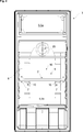
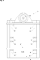
- Figure 1 – is a schematic partial front view of a refrigeration appliance according to an embodiment of the present invention, showing an intermediate shelf assembly being supported by an upper shelf-support;
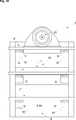
- Figure 2 – is a schematic partial front view of the refrigeration appliance according to an embodiment of the present invention, showing the intermediate shelf assembly being supported by a lower shelf-support;
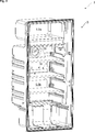
- Figure 3 – is a schematic partial perspective view of the refrigeration appliance according to an embodiment of the present invention, showing the intermediate shelf assembly being supported by the upper shelf-support;
- Figure 4 – is a schematic partial perspective view of the refrigeration appliance according to an embodiment of the present invention, showing a shield and the intermediate shelf prior to assembly;
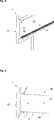
- Figure 5 – is a schematic partial enlarged perspective view of the shield of the shelf assembly according to an embodiment of the present invention.
- Figure 6 – is a schematic partial enlarged perspective view of the shelf assembly according to an embodiment of the present invention.
- Figure 7 – is a schematic partial perspective view of the refrigeration appliance according to an embodiment of the present invention, showing the intermediate shelf assembly being supported by the upper shelf-support;
- Figure 8 – is a schematic partial perspective view of the refrigeration appliance according to an embodiment of the present invention, showing the intermediate shelf assembly being supported by the lower shelf-support;
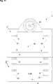
- Figure 9 – is a schematic partial front view of the refrigeration appliance according to an embodiment of the present invention, showing the intermediate shelf assembly being removed;
- Figure 10 – is a schematic partial front view of the refrigeration appliance according to an embodiment of the present invention, showing the intermediate shelf assembly being supported by the upper shelf-support;
- Figure 11 – is a schematic partial front view of the refrigeration appliance according to an embodiment of the present invention, showing the intermediate shelf assembly being supported by the lower shelf-support;
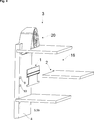
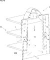
- Figure 12 – is a schematic partial perspective rear view of the refrigeration appliance according to an embodiment of the present invention, showing the intermediate shelf assembly being supported by the upper shelf-support, and the solid arrows showing a flow direction of cooling air in a duct.
- the shield (1) is suitable for use with a shelf (2) in a refrigeration appliance (3), in particular a domestic refrigerator (3) (Figs. 1 to 12).
- the shelf (2) comprises a phase change material (4) (Fig. 6).
- the refrigeration appliance (3) of the present invention comprises an upper shelf-support (6) and a lower shelf-support (7) which are successively provided one above the other, an evaporator cover (8) which includes upper outlets (9) which are arranged to discharge cooling air towards a lower side of a shelf (2) which is supported by the upper shelf-support (6) and lower outlets (10) which are arranged to discharge cooling air towards a lower side of a shelf (2) which is supported by the lower shelf-support (7) (Figs. 1 to 12).
- the shield (1) of the present invention comprises a mounting portion (11) which is configured to detachably attach to a rear side of the shelf (2) and a cover portion (12) which is configured to abut against the evaporator cover (8), wherein a size and a shape of the cover portion (12) is configured such that when the shelf (2) is supported by the upper shelf-support (6), the lower outlets (10) are obstructed by a lower part of the cover portion (12) and the upper outlets (9) remain unobstructed, and when the shelf (2) is supported by the lower shelf-support (7), the upper outlets (9) are obstructed by an upper part of the cover portion (12) and the lower outlets (10) remain unobstructed (Figs. 1 to 12).
- the shelf (2) can be efficiently cooled at a predetermined rate even when the user changes a position of the shelf (2). Consequently, in case of power outage, the articles can be reliably prevented from undergoing a temperature rise (Figs. 10 and 11).
- the mounting portion (11) has a slot (13) into which the rear side of the shelf (2) can be detachably attached by compression fit (Figs. 4 to 6).
- the shield (1) and the shelf (2) can be easily assembled together by a user having ordinary skills.
- the slot (13) has an upper ribbed surface (14) and a lower ribbed surface (15) which are configured to respectively abut against the upper surface and the lower surface of the shelf (2) (Figs. 4 to 5). Thereby, a grip between the shield (1) and the shelf (2) has been improved.
- the shelf assembly (16) of the present invention comprises the shield (1) and the shelf (2) (Figs. 4 to 6).
- a chamber (17) which is fillable with a phase change material (4) is arranged into a body (18) of the shelf (2) (Fig. 6).
- the shelf (2) is slidably mountable to either one of the upper shelf-support (6) and the lower shelf-support (7) (Figs. 1 to 3).
- the phase change material (4) has a liquid/solid phase change temperature in a range of 1 °C to 5 °C.
- the shelf (2) is particularly suitable for use in fresh food compartment.
- the refrigeration appliance (3) of the present invention is not limited to a single group consisting of the upper shelf-support (6) and the lower shelf-support (7). Thus, the present invention is applicable to a plurality of such groups.
- the refrigeration appliance (3) of the present invention comprises one or more than one group of shelf-supports (6,7), wherein each group has an upper shelf-support (6) and a lower shelf-support (7) which are successively arranged one above the other, and wherein the groups are successively arranged one above the other, an evaporator cover (8) which includes one or more than one group of upper outlets (9) and lower outlets (10), wherein in each group, the upper outlets (9) are arranged to discharge cooling air towards a lower side of a shelf (2) which is supported by the upper shelf-support (6) of the respective group, and the lower outlets (10) are arranged to discharge cooling air towards a lower side of a shelf (2) which is supported by the lower shelf-support (7) of the respective group and one or more than one shelf assembly (16) as defined in claim 4 or 5.
- FIG. 1 For a better illustration of the groups, the drawings show only one shield (1) which is fitted to a shelf (2), in particular the intermediate shelf (2) (Figs. 1 to 12). However, in the present invention a shield (1) can be fitted to an upper shelf (2 ⁇ ) and a lower shelf (2 ⁇ ⁇ ) (Figs. 9 to 11).
- the refrigeration appliance (3) comprises three groups of shelf-supports (6, 7) and three shelf assemblies (16), wherein each shelf assembly (16) is provided for use with a respective group of shelf-supports (6, 7) (Figs. 1 to 12).
- the upper outlets (9) and the lower outlets (10) of each group respectively include two air discharge openings.
- discharge openings are symmetrically arranged on the left side and the right side of the evaporator cover (8) (Fig. 9).
- the refrigeration appliance (3) comprises a freezer compartment (5a) and a fresh food compartment (5b), wherein said one or more than one group of shelf-supports (6-7) are arranged into the fresh food compartment (5b) (Figs. 1 to 3).
- the evaporator cover (8) has a duct (19) which is formed on its rear part and a fan assembly (20) which is built into its upper part.
- the fresh food evaporator is arranged in heat-exchange with the air in the duct (19).
- the upper outlets (9) and the lower outlets (10) are arranged in fluid communication with the duct (19).
- the fan assembly (20) draws the air out of the fresh food compartment (5b) into the duct (19) so as to circulate the air via the fresh food evaporator into the fresh food compartment (5b). The air is only discharged through the upper outlets (9) and lower outlets (10) which are not obstructed by the shield (1).
- a shield (1) has been provided which is easy to install, maintenance-free, and cost effective. Most importantly, by virtue of the shield (1), the usability of the shelf (2) has been improved while also securing a desired efficiency of the cooling process of the phase change material and safeguarding proper refrigeration of the articles.
Landscapes
- Engineering & Computer Science (AREA)
- Chemical & Material Sciences (AREA)
- Combustion & Propulsion (AREA)
- Physics & Mathematics (AREA)
- Mechanical Engineering (AREA)
- Thermal Sciences (AREA)
- General Engineering & Computer Science (AREA)
- Devices That Are Associated With Refrigeration Equipment (AREA)
- Cold Air Circulating Systems And Constructional Details In Refrigerators (AREA)
Abstract
The present invention relates to a shield (1) for use with a shelf (2) in a refrigeration appliance (3) comprising an upper shelf-support (6) and a lower shelf-support (7) which are successively provided one above the other, an evaporator cover (8) which includes upper outlets (9) arranged to discharge cooling air towards a lower side of a shelf (2) supported by the upper shelf-support (6) and lower outlets (10) arranged to discharge cooling air towards a lower side of a shelf (2) supported by the lower shelf-support (7).
Description
The present invention relates to a shelf for use in a refrigeration appliance. The present invention particularly relates to a shelf which has a phase change material (pcm). The present invention more particularly relates to a cooling facility for regulating an air flow via an evaporator towards a shelf which has a phase change material.
The no-frost technology constitutes an effective method of reducing humidity in a refrigeration compartment to prevent formation of frost on the inner walls thereof and on the articles stored therein. A refrigeration appliance utilizing the no-frost technology typically includes a compartment for accommodating the articles to be refrigerated,
a refrigeration circuit which includes an evaporator disposed at a location outside the refrigeration compartment and a circulation duct for conveying by means of a fan the air inside the refrigeration compartment towards the evaporator, and for subsequently discharging the air into the refrigeration compartment. Thereby, the moisture in the circulated air freezes on the surface of the evaporator as the refrigerant evaporates. During the circulation of the air, heat is also transferred with the circulated air from the articles stored in the refrigerating compartment to the evaporator through convection. As the moisture in the circulated air freezes on the surface of the evaporator, the proper functioning of the evaporator starts degrading. Therefore, the evaporator must be eventually defrosted.
a refrigeration circuit which includes an evaporator disposed at a location outside the refrigeration compartment and a circulation duct for conveying by means of a fan the air inside the refrigeration compartment towards the evaporator, and for subsequently discharging the air into the refrigeration compartment. Thereby, the moisture in the circulated air freezes on the surface of the evaporator as the refrigerant evaporates. During the circulation of the air, heat is also transferred with the circulated air from the articles stored in the refrigerating compartment to the evaporator through convection. As the moisture in the circulated air freezes on the surface of the evaporator, the proper functioning of the evaporator starts degrading. Therefore, the evaporator must be eventually defrosted.
During a power outage, a compressor of the refrigeration circuit and the fan stops, in turn, the temperature inside the refrigeration compartment starts increasing. Consequently, an actual expiration date of the articles gets closer so that these are likely to be spoiled or poisonous before being consumed by a user.
It is common practice to utilize phase change materials to retard a temperature increase inside the refrigeration compartment during power outage. Thereby, a power outage period can be safely bridged.
Several techniques have been devised to utilize phase change materials in refrigeration appliances. In a commonly known technique the phase change material is filled into a shelf which carries the articles.
WO 97/45685 discloses a domestic refrigerator which has a freezer compartment and a fresh food compartment. The freezer compartment is provided with a rack including a phase change material. In case of power outage the user replaces a rack of the fresh food compartment with the rack of the freezer compartment which includes the phase change material.
In general, it is preferred to utilize a phase change material which has a large heat capacity. Thereby, large amounts of thermal energy can be stored and the articles can be effectively prevented from undergoing a temperature rise. However, a phase change material having a large heat capacity must be sufficiently cooled in order to achieve its full effect. Thus, there is a risk that the articles are excessively refrigerated if the phase change material is cooled intensively.
An objective of the present invention is to provide a cooling facility for use with a shelf in a refrigeration appliance which overcomes the aforementioned drawbacks of the prior art and which enables effective and efficient cooling of a phase change material inside a shelf without compromising proper refrigeration of the articles placed thereon.
This objective has been achieved by the shield according to the present invention as defined in claim 1, the shelf assembly according to the present invention as defined in claim 4, and the refrigeration appliance according to the present invention as defined in claim 6. Further achievements have been attained by the subject-matters respectively defined in the dependent claims.
The shield of the present invention is suitable for use with a shelf in a refrigeration appliance, in particular a domestic refrigerator. The shelf comprises a phase change material. The refrigeration appliance of the present invention comprises an upper shelf-support and a lower shelf-support which are successively provided one above the other, an evaporator cover which includes upper outlets which are arranged to discharge cooling air towards a lower side of a shelf which is supported by the upper shelf-support and lower outlets which are arranged to discharge cooling air towards a lower side of a shelf which is supported by the lower shelf-support. The shield of the present invention comprises a mounting portion which is configured to detachably attach to a rear side of the shelf and a cover portion which is configured to abut against the evaporator cover, wherein a size and a shape of the cover portion is configured such that when the shelf is supported by the upper shelf-support, the lower outlets are obstructed by a lower part of the cover portion and the upper outlets remain unobstructed, and when the shelf is supported by the lower shelf-support, the upper outlets are obstructed by an upper part of the cover portion and the lower outlets remain unobstructed.
In an embodiment, the shield and the shelf can be mounted by compression fit. Thereby, a user having ordinary skills can easily assemble the shield and the shelf.
In another embodiment, the shelf includes a phase change material which has a liquid/solid phase change temperature in a range of 1°C to 5°C. Thereby, the shelf is particularly suited for the use in a fresh food compartment.
By virtue of the shield, only a lower side of the shelf is subjected to a cooling air flow regardless of a position of the shelf. Thereby, the shelf can be effectively and more efficiently cooled at relatively high flow rates of cooling air. Moreover, the lower side of the shelf can be always cooled under the same conditions so that the phase change material can rapidly achieve its full effect. Thereby, the articles can be reliably prevented from undergoing a temperature rise in case of power outage. Also by virtue of the cover portion of the shield, the articles can be prevented from being excessively refrigerated since the cooling air is exclusively directed to a lower side of the shelf. By the present invention a shield has been provided which is easy to install, maintenance-free, and cost effective. Most importantly, the usability of the shelf has been improved without degrading a cooling process of the phase change material and the articles.
Additional advantages of the shield according to the present invention and the refrigeration appliance of the present invention will become apparent with the detailed description of the embodiments with reference to the accompanying drawings in which:
Figure 1 – is a schematic partial front view of a refrigeration appliance according to an embodiment of the present invention, showing an intermediate shelf assembly being supported by an upper shelf-support;
Figure 2 – is a schematic partial front view of the refrigeration appliance according to an embodiment of the present invention, showing the intermediate shelf assembly being supported by a lower shelf-support;
Figure 3 – is a schematic partial perspective view of the refrigeration appliance according to an embodiment of the present invention, showing the intermediate shelf assembly being supported by the upper shelf-support;
Figure 4 – is a schematic partial perspective view of the refrigeration appliance according to an embodiment of the present invention, showing a shield and the intermediate shelf prior to assembly;
Figure 5 – is a schematic partial enlarged perspective view of the shield of the shelf assembly according to an embodiment of the present invention;
Figure 6 – is a schematic partial enlarged perspective view of the shelf assembly according to an embodiment of the present invention;
Figure 7 – is a schematic partial perspective view of the refrigeration appliance according to an embodiment of the present invention, showing the intermediate shelf assembly being supported by the upper shelf-support;
Figure 8 – is a schematic partial perspective view of the refrigeration appliance according to an embodiment of the present invention, showing the intermediate shelf assembly being supported by the lower shelf-support;
Figure 9 – is a schematic partial front view of the refrigeration appliance according to an embodiment of the present invention, showing the intermediate shelf assembly being removed;
Figure 10 – is a schematic partial front view of the refrigeration appliance according to an embodiment of the present invention, showing the intermediate shelf assembly being supported by the upper shelf-support;
Figure 11 – is a schematic partial front view of the refrigeration appliance according to an embodiment of the present invention, showing the intermediate shelf assembly being supported by the lower shelf-support;
Figure 12 – is a schematic partial perspective rear view of the refrigeration appliance according to an embodiment of the present invention, showing the intermediate shelf assembly being supported by the upper shelf-support, and the solid arrows showing a flow direction of cooling air in a duct.
The reference signs appearing on the drawings relate to the following technical features.
- Shield
- Shelf
2´ Shelf
2´´ Shelf
3. Refrigeration appliance
4. Phase change material (pcm)
5. Refrigeration compartment
5a. Freezer compartment
5b. Fresh food compartment
6. Upper shelf-support
7. Lower shelf-support
8. Evaporator cover
9. Upper outlets
9´ Upper outlets
9´´ Upper outlets
10. Lower outlets
10´ Lower outlets
10´´ Lower outlets
11. Mounting portion
12. Cover portion
13. Slot
14. Upper ribbed surface
15. Lower ribbed surface
16. Shelf assembly
17. Chamber
18. Shelf body
19. Duct
20. Fan assembly
The shield (1) is suitable for use with a shelf (2) in a refrigeration appliance (3), in particular a domestic refrigerator (3) (Figs. 1 to 12). The shelf (2) comprises a phase change material (4) (Fig. 6).
The refrigeration appliance (3) comprises a refrigeration compartment (5, 5a, 5b) (Figs. 1 to 12).
The refrigeration appliance (3) of the present invention comprises an upper shelf-support (6) and a lower shelf-support (7) which are successively provided one above the other, an evaporator cover (8) which includes upper outlets (9) which are arranged to discharge cooling air towards a lower side of a shelf (2) which is supported by the upper shelf-support (6) and lower outlets (10) which are arranged to discharge cooling air towards a lower side of a shelf (2) which is supported by the lower shelf-support (7) (Figs. 1 to 12).
The shield (1) of the present invention comprises a mounting portion (11) which is configured to detachably attach to a rear side of the shelf (2) and a cover portion (12) which is configured to abut against the evaporator cover (8), wherein a size and a shape of the cover portion (12) is configured such that when the shelf (2) is supported by the upper shelf-support (6), the lower outlets (10) are obstructed by a lower part of the cover portion (12) and the upper outlets (9) remain unobstructed, and when the shelf (2) is supported by the lower shelf-support (7), the upper outlets (9) are obstructed by an upper part of the cover portion (12) and the lower outlets (10) remain unobstructed (Figs. 1 to 12). Thereby, regardless of a position of the shelf (2), only a lower side thereof is subjected to a cooling air flow and the articles are prevented from being excessively refrigerated. Thus, the shelf (2) can be efficiently cooled at a predetermined rate even when the user changes a position of the shelf (2). Consequently, in case of power outage, the articles can be reliably prevented from undergoing a temperature rise (Figs. 10 and 11).
In an embodiment, the mounting portion (11) has a slot (13) into which the rear side of the shelf (2) can be detachably attached by compression fit (Figs. 4 to 6). Thereby, the shield (1) and the shelf (2) can be easily assembled together by a user having ordinary skills.
In a version of this embodiment, the slot (13) has an upper ribbed surface (14) and a lower ribbed surface (15) which are configured to respectively abut against the upper surface and the lower surface of the shelf (2) (Figs. 4 to 5). Thereby, a grip between the shield (1) and the shelf (2) has been improved.
The shelf assembly (16) of the present invention comprises the shield (1) and the shelf (2) (Figs. 4 to 6). A chamber (17) which is fillable with a phase change material (4) is arranged into a body (18) of the shelf (2) (Fig. 6). The shelf (2) is slidably mountable to either one of the upper shelf-support (6) and the lower shelf-support (7) (Figs. 1 to 3).
In another embodiment, the phase change material (4) has a liquid/solid phase change temperature in a range of 1 °C to 5 °C. In this embodiment, the shelf (2) is particularly suitable for use in fresh food compartment.
The refrigeration appliance (3) of the present invention is not limited to a single group consisting of the upper shelf-support (6) and the lower shelf-support (7). Thus, the present invention is applicable to a plurality of such groups. The refrigeration appliance (3) of the present invention comprises one or more than one group of shelf-supports (6,7), wherein each group has an upper shelf-support (6) and a lower shelf-support (7) which are successively arranged one above the other, and wherein the groups are successively arranged one above the other, an evaporator cover (8) which includes one or more than one group of upper outlets (9) and lower outlets (10), wherein in each group, the upper outlets (9) are arranged to discharge cooling air towards a lower side of a shelf (2) which is supported by the upper shelf-support (6) of the respective group, and the lower outlets (10) are arranged to discharge cooling air towards a lower side of a shelf (2) which is supported by the lower shelf-support (7) of the respective group and one or more than one shelf assembly (16) as defined in claim 4 or 5.
For a better illustration of the groups, the drawings show only one shield (1) which is fitted to a shelf (2), in particular the intermediate shelf (2) (Figs. 1 to 12). However, in the present invention a shield (1) can be fitted to an upper shelf (2´) and a lower shelf (2´´) (Figs. 9 to 11).
In another embodiment, the refrigeration appliance (3) comprises three groups of shelf-supports (6, 7) and three shelf assemblies (16), wherein each shelf assembly (16) is provided for use with a respective group of shelf-supports (6, 7) (Figs. 1 to 12).
In another embodiment, the upper outlets (9) and the lower outlets (10) of each group respectively include two air discharge openings.
In a version of this embodiment, discharge openings are symmetrically arranged on the left side and the right side of the evaporator cover (8) (Fig. 9).
In another embodiment, the refrigeration appliance (3) comprises a freezer compartment (5a) and a fresh food compartment (5b), wherein said one or more than one group of shelf-supports (6-7) are arranged into the fresh food compartment (5b) (Figs. 1 to 3).
In another embodiment, the evaporator cover (8) has a duct (19) which is formed on its rear part and a fan assembly (20) which is built into its upper part. In this embodiment, the fresh food evaporator is arranged in heat-exchange with the air in the duct (19). In addition, the upper outlets (9) and the lower outlets (10) are arranged in fluid communication with the duct (19). In operation, the fan assembly (20) draws the air out of the fresh food compartment (5b) into the duct (19) so as to circulate the air via the fresh food evaporator into the fresh food compartment (5b). The air is only discharged through the upper outlets (9) and lower outlets (10) which are not obstructed by the shield (1).
By the present invention, a shield (1) has been provided which is easy to install, maintenance-free, and cost effective. Most importantly, by virtue of the shield (1), the usability of the shelf (2) has been improved while also securing a desired efficiency of the cooling process of the phase change material and safeguarding proper refrigeration of the articles.
Claims (10)
- A shield (1) suitable for use with a shelf (2) in a refrigeration appliance (3), in particular a domestic refrigerator (3), wherein the shelf (2) comprises a phase change material (4), and the refrigeration appliance (3) comprises a refrigeration compartment (5, 5a, 5b), an upper shelf-support (6) and a lower shelf-support (7) which are successively provided one above the other, an evaporator cover (8) which includes upper outlets (9) which are arranged to discharge cooling air towards a lower side of a shelf (2) which is supported by the upper shelf-support (6) and lower outlets (10) which are arranged to discharge cooling air towards a lower side of a shelf (2) which is supported by the lower shelf-support (7),characterized in that- a mounting portion (11) which is configured to detachably attach to a rear side of the shelf (2) and- a cover portion (12) which is configured to abut against the evaporator cover (8), wherein a size and a shape of the cover portion (12) is configured such thatwhen the shelf (2) is supported by the upper shelf-support (6), the lower outlets (10) are obstructed by a lower part of the cover portion (12) and the upper outlets (9) remain unobstructed andwhen the shelf (2) is supported by the lower shelf-support (7), the upper outlets (9) are obstructed by an upper part of the cover portion (12) and the lower outlets (10) remain unobstructed.
- The shield (1) according to claim 1, characterized in that the mounting portion (11) has a slot (13) into which the rear side of the shelf (2) can be detachably attached by compression fit.
- The shield (1) according to claim 2, characterized in that the slot (13) has an upper ribbed surface (14) and a lower ribbed surface (15) which are configured to respectively abut against the upper surface and the lower surface of the shelf (2).
- A shelf assembly (16) for use in a refrigeration appliance (3), in particular a domestic refrigerator (3), wherein the refrigeration appliance (3) comprises a refrigeration compartment (5, 5a, 5b), an upper shelf-support (6) and a lower shelf-support (7) which are successively provided one above the other, an evaporator cover (8) which includes upper outlets (9) which are arranged to discharge cooling air towards a lower side of a shelf (2) which is supported by the upper shelf-support (6) and lower outlets (10) which are arranged to discharge cooling air towards a lower side of a shelf (2) which is supported by the lower shelf-support (7), the shelf assembly (16) comprising-a shelf (2) for carrying articles to be refrigerated, wherein the shelf (2) is slidably mountable to either one of the upper shelf-support (6) and the lower shelf-support (7),- a chamber (17) which is fillable with a phase change material (4), wherein the chamber (17) is arranged into a body (18) of the shelf (2),characterized in that a shield (1) as defined in any one of claims 1 to 3.
- The shelf assembly (16) according to claim 4, characterized in that the phase change material (4) has a liquid/solid phase change temperature in a range of 1 °C to 5 °C.
- A refrigeration appliance (3), in particular a domestic refrigerator (3) comprisinga refrigeration compartment (5, 5a, 5b),characterized in that- one or more than one group of shelf-supports (6,7), wherein each group has an upper shelf-support (6) and a lower shelf-support (7) which are successively arranged one above the other, and wherein the groups are successively arranged one above the other,- an evaporator cover (8) which includes one or more than one group of upper outlets (9) and lower outlets (10), wherein in each group, the upper outlets (9) are arranged to discharge cooling air towards a lower side of a shelf (2) which is supported by the upper shelf-support (6) of the same respective group, and the lower outlets (10) are arranged to discharge cooling air towards a lower side of a shelf (2) which is supported by the lower shelf-support (7) of the same respective group and- one or more than one shelf assembly (16) as defined in claim 4 or 5.
- The refrigeration appliance (3) according to claim 6, characterized in that three groups of shelf-supports (6, 7) and three shelf assemblies (16), wherein each shelf assembly (16) is provided for use with a respective group of shelf-supports (6, 7).
- The refrigeration appliance (3) according to claim 6 or 7, characterized in that the upper outlets (9) and the lower outlets (10) of each group respectively include two air discharge openings.
- The refrigeration appliance (3) according to any one of claim 6 to 8, characterized in that a freezer compartment (5a) and a fresh food compartment (5b), wherein said one or more than one group of shelf-supports (6-7) are arranged into the fresh food compartment (5b).
- The refrigeration appliance (3) according to claim 9, characterized in that the evaporator cover (8) has a duct (19) which is formed at a rear part thereof, and a fan assembly (20) which is built-in at an upper part thereof, wherein a fresh food evaporator is arranged in heat-exchange with the air in the duct (19), wherein the upper outlets (9) and the lower outlets (10) are arranged in fluid communication with the duct (19), and wherein the fan assembly (20) is configured to draw the air out of the fresh food compartment (5b) into the duct (19) so as to circulate the cooling air via the fresh food evaporator and through the upper outlets (9) and the lower outlets (10) into the fresh food compartment (5b).
Priority Applications (1)
| Application Number | Priority Date | Filing Date | Title |
|---|---|---|---|
| PCT/EP2014/053870 WO2015127977A1 (en) | 2014-02-27 | 2014-02-27 | Shield for use with a shelf in a refrigeration appliance |
Applications Claiming Priority (1)
| Application Number | Priority Date | Filing Date | Title |
|---|---|---|---|
| PCT/EP2014/053870 WO2015127977A1 (en) | 2014-02-27 | 2014-02-27 | Shield for use with a shelf in a refrigeration appliance |
Publications (1)
| Publication Number | Publication Date |
|---|---|
| WO2015127977A1 true WO2015127977A1 (en) | 2015-09-03 |
Family
ID=50241379
Family Applications (1)
| Application Number | Title | Priority Date | Filing Date |
|---|---|---|---|
| PCT/EP2014/053870 Ceased WO2015127977A1 (en) | 2014-02-27 | 2014-02-27 | Shield for use with a shelf in a refrigeration appliance |
Country Status (1)
| Country | Link |
|---|---|
| WO (1) | WO2015127977A1 (en) |
Citations (6)
| Publication number | Priority date | Publication date | Assignee | Title |
|---|---|---|---|---|
| FR2262913A1 (en) * | 1974-03-04 | 1975-10-03 | Tripier Jean Claude | Controlled temp. proving cupboard for bakers dough - has adjustably spacable shelves with horizontal air passages |
| US5720185A (en) * | 1995-06-16 | 1998-02-24 | Daewoo Electronics Co., Ltd. | Refrigerator having a cool air dispersing shelf |
| DE29713567U1 (en) * | 1997-07-30 | 1998-11-26 | AEG Hausgeräte GmbH, 90429 Nürnberg | Refrigerator and / or freezer |
| US6044654A (en) * | 1997-04-25 | 2000-04-04 | Mitsubishi Denki Kabushiki Kaisha | Refrigerator |
| US6732537B1 (en) * | 2003-03-12 | 2004-05-11 | Maytag Corporation | Ice maker air delivery assembly |
| WO2008061840A2 (en) * | 2006-11-22 | 2008-05-29 | Whirlpool Corporation | Cooling shelf for refrigerator, and refrigerator incorporating this shelf |
-
2014
- 2014-02-27 WO PCT/EP2014/053870 patent/WO2015127977A1/en not_active Ceased
Patent Citations (6)
| Publication number | Priority date | Publication date | Assignee | Title |
|---|---|---|---|---|
| FR2262913A1 (en) * | 1974-03-04 | 1975-10-03 | Tripier Jean Claude | Controlled temp. proving cupboard for bakers dough - has adjustably spacable shelves with horizontal air passages |
| US5720185A (en) * | 1995-06-16 | 1998-02-24 | Daewoo Electronics Co., Ltd. | Refrigerator having a cool air dispersing shelf |
| US6044654A (en) * | 1997-04-25 | 2000-04-04 | Mitsubishi Denki Kabushiki Kaisha | Refrigerator |
| DE29713567U1 (en) * | 1997-07-30 | 1998-11-26 | AEG Hausgeräte GmbH, 90429 Nürnberg | Refrigerator and / or freezer |
| US6732537B1 (en) * | 2003-03-12 | 2004-05-11 | Maytag Corporation | Ice maker air delivery assembly |
| WO2008061840A2 (en) * | 2006-11-22 | 2008-05-29 | Whirlpool Corporation | Cooling shelf for refrigerator, and refrigerator incorporating this shelf |
Similar Documents
| Publication | Publication Date | Title |
|---|---|---|
| JP6405523B2 (en) | refrigerator | |
| JP6422513B2 (en) | Freezer refrigerator | |
| US9772130B2 (en) | Refrigerator and method for controlling a refrigerator | |
| CN109990529B (en) | refrigerator | |
| KR20090012689A (en) | Refrigerator with refrigeration system in the ice compartment on the door | |
| KR20140075301A (en) | Refrigerator | |
| KR20090006612A (en) | Refrigerator | |
| EP2593734B1 (en) | No-frost refrigerator | |
| CN206113483U (en) | Refrigerator | |
| KR100633149B1 (en) | Refrigerator | |
| EP3271669B1 (en) | Refrigerator | |
| KR20160090690A (en) | Refrigerator and conrtol method thereof | |
| KR20090092396A (en) | Refrigerator | |
| WO2012169573A1 (en) | Refrigerator | |
| JP2014048029A (en) | Refrigerator | |
| JP2015148403A (en) | refrigerator | |
| WO2012007807A2 (en) | Lighting system for refrigerators | |
| KR20080024479A (en) | Refrigeration and / or refrigeration unit | |
| EP3507551A1 (en) | Refrigerating appliance | |
| US10488102B2 (en) | Household cooling appliance with an ice tray and a cooling device in a door | |
| US20200011584A1 (en) | Refrigerator and Support Device for Refrigerator | |
| WO2010133559A2 (en) | Refrigerator | |
| WO2016070893A1 (en) | Refrigeration appliance with improved refrigeration performance and energy consumption | |
| EP3034971A1 (en) | Refrigeration appliance, in particular for household use, and relative method of realization | |
| EP3497386B1 (en) | Refrigeration appliance with zero-degree compartment having optimized structure for cooling |
Legal Events
| Date | Code | Title | Description |
|---|---|---|---|
| 121 | Ep: the epo has been informed by wipo that ep was designated in this application |
Ref document number: 14709211 Country of ref document: EP Kind code of ref document: A1 |
|
| NENP | Non-entry into the national phase |
Ref country code: DE |
|
| 122 | Ep: pct application non-entry in european phase |
Ref document number: 14709211 Country of ref document: EP Kind code of ref document: A1 |