WO2015125407A1 - Vehicle hybrid system - Google Patents
Vehicle hybrid system Download PDFInfo
- Publication number
- WO2015125407A1 WO2015125407A1 PCT/JP2015/000107 JP2015000107W WO2015125407A1 WO 2015125407 A1 WO2015125407 A1 WO 2015125407A1 JP 2015000107 W JP2015000107 W JP 2015000107W WO 2015125407 A1 WO2015125407 A1 WO 2015125407A1
- Authority
- WO
- WIPO (PCT)
- Prior art keywords
- motor generator
- engine
- vehicle
- transmission
- power connection
- Prior art date
Links
Images


Classifications
-
- B—PERFORMING OPERATIONS; TRANSPORTING
- B60—VEHICLES IN GENERAL
- B60W—CONJOINT CONTROL OF VEHICLE SUB-UNITS OF DIFFERENT TYPE OR DIFFERENT FUNCTION; CONTROL SYSTEMS SPECIALLY ADAPTED FOR HYBRID VEHICLES; ROAD VEHICLE DRIVE CONTROL SYSTEMS FOR PURPOSES NOT RELATED TO THE CONTROL OF A PARTICULAR SUB-UNIT
- B60W20/00—Control systems specially adapted for hybrid vehicles
- B60W20/10—Controlling the power contribution of each of the prime movers to meet required power demand
-
- B—PERFORMING OPERATIONS; TRANSPORTING
- B60—VEHICLES IN GENERAL
- B60K—ARRANGEMENT OR MOUNTING OF PROPULSION UNITS OR OF TRANSMISSIONS IN VEHICLES; ARRANGEMENT OR MOUNTING OF PLURAL DIVERSE PRIME-MOVERS IN VEHICLES; AUXILIARY DRIVES FOR VEHICLES; INSTRUMENTATION OR DASHBOARDS FOR VEHICLES; ARRANGEMENTS IN CONNECTION WITH COOLING, AIR INTAKE, GAS EXHAUST OR FUEL SUPPLY OF PROPULSION UNITS IN VEHICLES
- B60K6/00—Arrangement or mounting of plural diverse prime-movers for mutual or common propulsion, e.g. hybrid propulsion systems comprising electric motors and internal combustion engines ; Control systems therefor, i.e. systems controlling two or more prime movers, or controlling one of these prime movers and any of the transmission, drive or drive units Informative references: mechanical gearings with secondary electric drive F16H3/72; arrangements for handling mechanical energy structurally associated with the dynamo-electric machine H02K7/00; machines comprising structurally interrelated motor and generator parts H02K51/00; dynamo-electric machines not otherwise provided for in H02K see H02K99/00
- B60K6/20—Arrangement or mounting of plural diverse prime-movers for mutual or common propulsion, e.g. hybrid propulsion systems comprising electric motors and internal combustion engines ; Control systems therefor, i.e. systems controlling two or more prime movers, or controlling one of these prime movers and any of the transmission, drive or drive units Informative references: mechanical gearings with secondary electric drive F16H3/72; arrangements for handling mechanical energy structurally associated with the dynamo-electric machine H02K7/00; machines comprising structurally interrelated motor and generator parts H02K51/00; dynamo-electric machines not otherwise provided for in H02K see H02K99/00 the prime-movers consisting of electric motors and internal combustion engines, e.g. HEVs
- B60K6/22—Arrangement or mounting of plural diverse prime-movers for mutual or common propulsion, e.g. hybrid propulsion systems comprising electric motors and internal combustion engines ; Control systems therefor, i.e. systems controlling two or more prime movers, or controlling one of these prime movers and any of the transmission, drive or drive units Informative references: mechanical gearings with secondary electric drive F16H3/72; arrangements for handling mechanical energy structurally associated with the dynamo-electric machine H02K7/00; machines comprising structurally interrelated motor and generator parts H02K51/00; dynamo-electric machines not otherwise provided for in H02K see H02K99/00 the prime-movers consisting of electric motors and internal combustion engines, e.g. HEVs characterised by apparatus, components or means specially adapted for HEVs
- B60K6/26—Arrangement or mounting of plural diverse prime-movers for mutual or common propulsion, e.g. hybrid propulsion systems comprising electric motors and internal combustion engines ; Control systems therefor, i.e. systems controlling two or more prime movers, or controlling one of these prime movers and any of the transmission, drive or drive units Informative references: mechanical gearings with secondary electric drive F16H3/72; arrangements for handling mechanical energy structurally associated with the dynamo-electric machine H02K7/00; machines comprising structurally interrelated motor and generator parts H02K51/00; dynamo-electric machines not otherwise provided for in H02K see H02K99/00 the prime-movers consisting of electric motors and internal combustion engines, e.g. HEVs characterised by apparatus, components or means specially adapted for HEVs characterised by the motors or the generators
-
- B—PERFORMING OPERATIONS; TRANSPORTING
- B60—VEHICLES IN GENERAL
- B60K—ARRANGEMENT OR MOUNTING OF PROPULSION UNITS OR OF TRANSMISSIONS IN VEHICLES; ARRANGEMENT OR MOUNTING OF PLURAL DIVERSE PRIME-MOVERS IN VEHICLES; AUXILIARY DRIVES FOR VEHICLES; INSTRUMENTATION OR DASHBOARDS FOR VEHICLES; ARRANGEMENTS IN CONNECTION WITH COOLING, AIR INTAKE, GAS EXHAUST OR FUEL SUPPLY OF PROPULSION UNITS IN VEHICLES
- B60K6/00—Arrangement or mounting of plural diverse prime-movers for mutual or common propulsion, e.g. hybrid propulsion systems comprising electric motors and internal combustion engines ; Control systems therefor, i.e. systems controlling two or more prime movers, or controlling one of these prime movers and any of the transmission, drive or drive units Informative references: mechanical gearings with secondary electric drive F16H3/72; arrangements for handling mechanical energy structurally associated with the dynamo-electric machine H02K7/00; machines comprising structurally interrelated motor and generator parts H02K51/00; dynamo-electric machines not otherwise provided for in H02K see H02K99/00
- B60K6/20—Arrangement or mounting of plural diverse prime-movers for mutual or common propulsion, e.g. hybrid propulsion systems comprising electric motors and internal combustion engines ; Control systems therefor, i.e. systems controlling two or more prime movers, or controlling one of these prime movers and any of the transmission, drive or drive units Informative references: mechanical gearings with secondary electric drive F16H3/72; arrangements for handling mechanical energy structurally associated with the dynamo-electric machine H02K7/00; machines comprising structurally interrelated motor and generator parts H02K51/00; dynamo-electric machines not otherwise provided for in H02K see H02K99/00 the prime-movers consisting of electric motors and internal combustion engines, e.g. HEVs
- B60K6/22—Arrangement or mounting of plural diverse prime-movers for mutual or common propulsion, e.g. hybrid propulsion systems comprising electric motors and internal combustion engines ; Control systems therefor, i.e. systems controlling two or more prime movers, or controlling one of these prime movers and any of the transmission, drive or drive units Informative references: mechanical gearings with secondary electric drive F16H3/72; arrangements for handling mechanical energy structurally associated with the dynamo-electric machine H02K7/00; machines comprising structurally interrelated motor and generator parts H02K51/00; dynamo-electric machines not otherwise provided for in H02K see H02K99/00 the prime-movers consisting of electric motors and internal combustion engines, e.g. HEVs characterised by apparatus, components or means specially adapted for HEVs
- B60K6/38—Arrangement or mounting of plural diverse prime-movers for mutual or common propulsion, e.g. hybrid propulsion systems comprising electric motors and internal combustion engines ; Control systems therefor, i.e. systems controlling two or more prime movers, or controlling one of these prime movers and any of the transmission, drive or drive units Informative references: mechanical gearings with secondary electric drive F16H3/72; arrangements for handling mechanical energy structurally associated with the dynamo-electric machine H02K7/00; machines comprising structurally interrelated motor and generator parts H02K51/00; dynamo-electric machines not otherwise provided for in H02K see H02K99/00 the prime-movers consisting of electric motors and internal combustion engines, e.g. HEVs characterised by apparatus, components or means specially adapted for HEVs characterised by the driveline clutches
- B60K6/383—One-way clutches or freewheel devices
-
- B—PERFORMING OPERATIONS; TRANSPORTING
- B60—VEHICLES IN GENERAL
- B60K—ARRANGEMENT OR MOUNTING OF PROPULSION UNITS OR OF TRANSMISSIONS IN VEHICLES; ARRANGEMENT OR MOUNTING OF PLURAL DIVERSE PRIME-MOVERS IN VEHICLES; AUXILIARY DRIVES FOR VEHICLES; INSTRUMENTATION OR DASHBOARDS FOR VEHICLES; ARRANGEMENTS IN CONNECTION WITH COOLING, AIR INTAKE, GAS EXHAUST OR FUEL SUPPLY OF PROPULSION UNITS IN VEHICLES
- B60K6/00—Arrangement or mounting of plural diverse prime-movers for mutual or common propulsion, e.g. hybrid propulsion systems comprising electric motors and internal combustion engines ; Control systems therefor, i.e. systems controlling two or more prime movers, or controlling one of these prime movers and any of the transmission, drive or drive units Informative references: mechanical gearings with secondary electric drive F16H3/72; arrangements for handling mechanical energy structurally associated with the dynamo-electric machine H02K7/00; machines comprising structurally interrelated motor and generator parts H02K51/00; dynamo-electric machines not otherwise provided for in H02K see H02K99/00
- B60K6/20—Arrangement or mounting of plural diverse prime-movers for mutual or common propulsion, e.g. hybrid propulsion systems comprising electric motors and internal combustion engines ; Control systems therefor, i.e. systems controlling two or more prime movers, or controlling one of these prime movers and any of the transmission, drive or drive units Informative references: mechanical gearings with secondary electric drive F16H3/72; arrangements for handling mechanical energy structurally associated with the dynamo-electric machine H02K7/00; machines comprising structurally interrelated motor and generator parts H02K51/00; dynamo-electric machines not otherwise provided for in H02K see H02K99/00 the prime-movers consisting of electric motors and internal combustion engines, e.g. HEVs
- B60K6/22—Arrangement or mounting of plural diverse prime-movers for mutual or common propulsion, e.g. hybrid propulsion systems comprising electric motors and internal combustion engines ; Control systems therefor, i.e. systems controlling two or more prime movers, or controlling one of these prime movers and any of the transmission, drive or drive units Informative references: mechanical gearings with secondary electric drive F16H3/72; arrangements for handling mechanical energy structurally associated with the dynamo-electric machine H02K7/00; machines comprising structurally interrelated motor and generator parts H02K51/00; dynamo-electric machines not otherwise provided for in H02K see H02K99/00 the prime-movers consisting of electric motors and internal combustion engines, e.g. HEVs characterised by apparatus, components or means specially adapted for HEVs
- B60K6/38—Arrangement or mounting of plural diverse prime-movers for mutual or common propulsion, e.g. hybrid propulsion systems comprising electric motors and internal combustion engines ; Control systems therefor, i.e. systems controlling two or more prime movers, or controlling one of these prime movers and any of the transmission, drive or drive units Informative references: mechanical gearings with secondary electric drive F16H3/72; arrangements for handling mechanical energy structurally associated with the dynamo-electric machine H02K7/00; machines comprising structurally interrelated motor and generator parts H02K51/00; dynamo-electric machines not otherwise provided for in H02K see H02K99/00 the prime-movers consisting of electric motors and internal combustion engines, e.g. HEVs characterised by apparatus, components or means specially adapted for HEVs characterised by the driveline clutches
- B60K6/387—Actuated clutches, i.e. clutches engaged or disengaged by electric, hydraulic or mechanical actuating means
-
- B—PERFORMING OPERATIONS; TRANSPORTING
- B60—VEHICLES IN GENERAL
- B60K—ARRANGEMENT OR MOUNTING OF PROPULSION UNITS OR OF TRANSMISSIONS IN VEHICLES; ARRANGEMENT OR MOUNTING OF PLURAL DIVERSE PRIME-MOVERS IN VEHICLES; AUXILIARY DRIVES FOR VEHICLES; INSTRUMENTATION OR DASHBOARDS FOR VEHICLES; ARRANGEMENTS IN CONNECTION WITH COOLING, AIR INTAKE, GAS EXHAUST OR FUEL SUPPLY OF PROPULSION UNITS IN VEHICLES
- B60K6/00—Arrangement or mounting of plural diverse prime-movers for mutual or common propulsion, e.g. hybrid propulsion systems comprising electric motors and internal combustion engines ; Control systems therefor, i.e. systems controlling two or more prime movers, or controlling one of these prime movers and any of the transmission, drive or drive units Informative references: mechanical gearings with secondary electric drive F16H3/72; arrangements for handling mechanical energy structurally associated with the dynamo-electric machine H02K7/00; machines comprising structurally interrelated motor and generator parts H02K51/00; dynamo-electric machines not otherwise provided for in H02K see H02K99/00
- B60K6/20—Arrangement or mounting of plural diverse prime-movers for mutual or common propulsion, e.g. hybrid propulsion systems comprising electric motors and internal combustion engines ; Control systems therefor, i.e. systems controlling two or more prime movers, or controlling one of these prime movers and any of the transmission, drive or drive units Informative references: mechanical gearings with secondary electric drive F16H3/72; arrangements for handling mechanical energy structurally associated with the dynamo-electric machine H02K7/00; machines comprising structurally interrelated motor and generator parts H02K51/00; dynamo-electric machines not otherwise provided for in H02K see H02K99/00 the prime-movers consisting of electric motors and internal combustion engines, e.g. HEVs
- B60K6/42—Arrangement or mounting of plural diverse prime-movers for mutual or common propulsion, e.g. hybrid propulsion systems comprising electric motors and internal combustion engines ; Control systems therefor, i.e. systems controlling two or more prime movers, or controlling one of these prime movers and any of the transmission, drive or drive units Informative references: mechanical gearings with secondary electric drive F16H3/72; arrangements for handling mechanical energy structurally associated with the dynamo-electric machine H02K7/00; machines comprising structurally interrelated motor and generator parts H02K51/00; dynamo-electric machines not otherwise provided for in H02K see H02K99/00 the prime-movers consisting of electric motors and internal combustion engines, e.g. HEVs characterised by the architecture of the hybrid electric vehicle
- B60K6/44—Series-parallel type
- B60K6/442—Series-parallel switching type
-
- B—PERFORMING OPERATIONS; TRANSPORTING
- B60—VEHICLES IN GENERAL
- B60K—ARRANGEMENT OR MOUNTING OF PROPULSION UNITS OR OF TRANSMISSIONS IN VEHICLES; ARRANGEMENT OR MOUNTING OF PLURAL DIVERSE PRIME-MOVERS IN VEHICLES; AUXILIARY DRIVES FOR VEHICLES; INSTRUMENTATION OR DASHBOARDS FOR VEHICLES; ARRANGEMENTS IN CONNECTION WITH COOLING, AIR INTAKE, GAS EXHAUST OR FUEL SUPPLY OF PROPULSION UNITS IN VEHICLES
- B60K6/00—Arrangement or mounting of plural diverse prime-movers for mutual or common propulsion, e.g. hybrid propulsion systems comprising electric motors and internal combustion engines ; Control systems therefor, i.e. systems controlling two or more prime movers, or controlling one of these prime movers and any of the transmission, drive or drive units Informative references: mechanical gearings with secondary electric drive F16H3/72; arrangements for handling mechanical energy structurally associated with the dynamo-electric machine H02K7/00; machines comprising structurally interrelated motor and generator parts H02K51/00; dynamo-electric machines not otherwise provided for in H02K see H02K99/00
- B60K6/20—Arrangement or mounting of plural diverse prime-movers for mutual or common propulsion, e.g. hybrid propulsion systems comprising electric motors and internal combustion engines ; Control systems therefor, i.e. systems controlling two or more prime movers, or controlling one of these prime movers and any of the transmission, drive or drive units Informative references: mechanical gearings with secondary electric drive F16H3/72; arrangements for handling mechanical energy structurally associated with the dynamo-electric machine H02K7/00; machines comprising structurally interrelated motor and generator parts H02K51/00; dynamo-electric machines not otherwise provided for in H02K see H02K99/00 the prime-movers consisting of electric motors and internal combustion engines, e.g. HEVs
- B60K6/42—Arrangement or mounting of plural diverse prime-movers for mutual or common propulsion, e.g. hybrid propulsion systems comprising electric motors and internal combustion engines ; Control systems therefor, i.e. systems controlling two or more prime movers, or controlling one of these prime movers and any of the transmission, drive or drive units Informative references: mechanical gearings with secondary electric drive F16H3/72; arrangements for handling mechanical energy structurally associated with the dynamo-electric machine H02K7/00; machines comprising structurally interrelated motor and generator parts H02K51/00; dynamo-electric machines not otherwise provided for in H02K see H02K99/00 the prime-movers consisting of electric motors and internal combustion engines, e.g. HEVs characterised by the architecture of the hybrid electric vehicle
- B60K6/48—Parallel type
-
- B—PERFORMING OPERATIONS; TRANSPORTING
- B60—VEHICLES IN GENERAL
- B60K—ARRANGEMENT OR MOUNTING OF PROPULSION UNITS OR OF TRANSMISSIONS IN VEHICLES; ARRANGEMENT OR MOUNTING OF PLURAL DIVERSE PRIME-MOVERS IN VEHICLES; AUXILIARY DRIVES FOR VEHICLES; INSTRUMENTATION OR DASHBOARDS FOR VEHICLES; ARRANGEMENTS IN CONNECTION WITH COOLING, AIR INTAKE, GAS EXHAUST OR FUEL SUPPLY OF PROPULSION UNITS IN VEHICLES
- B60K6/00—Arrangement or mounting of plural diverse prime-movers for mutual or common propulsion, e.g. hybrid propulsion systems comprising electric motors and internal combustion engines ; Control systems therefor, i.e. systems controlling two or more prime movers, or controlling one of these prime movers and any of the transmission, drive or drive units Informative references: mechanical gearings with secondary electric drive F16H3/72; arrangements for handling mechanical energy structurally associated with the dynamo-electric machine H02K7/00; machines comprising structurally interrelated motor and generator parts H02K51/00; dynamo-electric machines not otherwise provided for in H02K see H02K99/00
- B60K6/20—Arrangement or mounting of plural diverse prime-movers for mutual or common propulsion, e.g. hybrid propulsion systems comprising electric motors and internal combustion engines ; Control systems therefor, i.e. systems controlling two or more prime movers, or controlling one of these prime movers and any of the transmission, drive or drive units Informative references: mechanical gearings with secondary electric drive F16H3/72; arrangements for handling mechanical energy structurally associated with the dynamo-electric machine H02K7/00; machines comprising structurally interrelated motor and generator parts H02K51/00; dynamo-electric machines not otherwise provided for in H02K see H02K99/00 the prime-movers consisting of electric motors and internal combustion engines, e.g. HEVs
- B60K6/50—Architecture of the driveline characterised by arrangement or kind of transmission units
- B60K6/54—Transmission for changing ratio
- B60K6/547—Transmission for changing ratio the transmission being a stepped gearing
-
- B—PERFORMING OPERATIONS; TRANSPORTING
- B60—VEHICLES IN GENERAL
- B60L—PROPULSION OF ELECTRICALLY-PROPELLED VEHICLES; SUPPLYING ELECTRIC POWER FOR AUXILIARY EQUIPMENT OF ELECTRICALLY-PROPELLED VEHICLES; ELECTRODYNAMIC BRAKE SYSTEMS FOR VEHICLES IN GENERAL; MAGNETIC SUSPENSION OR LEVITATION FOR VEHICLES; MONITORING OPERATING VARIABLES OF ELECTRICALLY-PROPELLED VEHICLES; ELECTRIC SAFETY DEVICES FOR ELECTRICALLY-PROPELLED VEHICLES
- B60L15/00—Methods, circuits, or devices for controlling the traction-motor speed of electrically-propelled vehicles
- B60L15/20—Methods, circuits, or devices for controlling the traction-motor speed of electrically-propelled vehicles for control of the vehicle or its driving motor to achieve a desired performance, e.g. speed, torque, programmed variation of speed
- B60L15/2009—Methods, circuits, or devices for controlling the traction-motor speed of electrically-propelled vehicles for control of the vehicle or its driving motor to achieve a desired performance, e.g. speed, torque, programmed variation of speed for braking
-
- B—PERFORMING OPERATIONS; TRANSPORTING
- B60—VEHICLES IN GENERAL
- B60L—PROPULSION OF ELECTRICALLY-PROPELLED VEHICLES; SUPPLYING ELECTRIC POWER FOR AUXILIARY EQUIPMENT OF ELECTRICALLY-PROPELLED VEHICLES; ELECTRODYNAMIC BRAKE SYSTEMS FOR VEHICLES IN GENERAL; MAGNETIC SUSPENSION OR LEVITATION FOR VEHICLES; MONITORING OPERATING VARIABLES OF ELECTRICALLY-PROPELLED VEHICLES; ELECTRIC SAFETY DEVICES FOR ELECTRICALLY-PROPELLED VEHICLES
- B60L15/00—Methods, circuits, or devices for controlling the traction-motor speed of electrically-propelled vehicles
- B60L15/20—Methods, circuits, or devices for controlling the traction-motor speed of electrically-propelled vehicles for control of the vehicle or its driving motor to achieve a desired performance, e.g. speed, torque, programmed variation of speed
- B60L15/2054—Methods, circuits, or devices for controlling the traction-motor speed of electrically-propelled vehicles for control of the vehicle or its driving motor to achieve a desired performance, e.g. speed, torque, programmed variation of speed by controlling transmissions or clutches
-
- B—PERFORMING OPERATIONS; TRANSPORTING
- B60—VEHICLES IN GENERAL
- B60L—PROPULSION OF ELECTRICALLY-PROPELLED VEHICLES; SUPPLYING ELECTRIC POWER FOR AUXILIARY EQUIPMENT OF ELECTRICALLY-PROPELLED VEHICLES; ELECTRODYNAMIC BRAKE SYSTEMS FOR VEHICLES IN GENERAL; MAGNETIC SUSPENSION OR LEVITATION FOR VEHICLES; MONITORING OPERATING VARIABLES OF ELECTRICALLY-PROPELLED VEHICLES; ELECTRIC SAFETY DEVICES FOR ELECTRICALLY-PROPELLED VEHICLES
- B60L50/00—Electric propulsion with power supplied within the vehicle
- B60L50/10—Electric propulsion with power supplied within the vehicle using propulsion power supplied by engine-driven generators, e.g. generators driven by combustion engines
- B60L50/16—Electric propulsion with power supplied within the vehicle using propulsion power supplied by engine-driven generators, e.g. generators driven by combustion engines with provision for separate direct mechanical propulsion
-
- B—PERFORMING OPERATIONS; TRANSPORTING
- B60—VEHICLES IN GENERAL
- B60L—PROPULSION OF ELECTRICALLY-PROPELLED VEHICLES; SUPPLYING ELECTRIC POWER FOR AUXILIARY EQUIPMENT OF ELECTRICALLY-PROPELLED VEHICLES; ELECTRODYNAMIC BRAKE SYSTEMS FOR VEHICLES IN GENERAL; MAGNETIC SUSPENSION OR LEVITATION FOR VEHICLES; MONITORING OPERATING VARIABLES OF ELECTRICALLY-PROPELLED VEHICLES; ELECTRIC SAFETY DEVICES FOR ELECTRICALLY-PROPELLED VEHICLES
- B60L7/00—Electrodynamic brake systems for vehicles in general
- B60L7/10—Dynamic electric regenerative braking
- B60L7/14—Dynamic electric regenerative braking for vehicles propelled by ac motors
-
- B—PERFORMING OPERATIONS; TRANSPORTING
- B60—VEHICLES IN GENERAL
- B60W—CONJOINT CONTROL OF VEHICLE SUB-UNITS OF DIFFERENT TYPE OR DIFFERENT FUNCTION; CONTROL SYSTEMS SPECIALLY ADAPTED FOR HYBRID VEHICLES; ROAD VEHICLE DRIVE CONTROL SYSTEMS FOR PURPOSES NOT RELATED TO THE CONTROL OF A PARTICULAR SUB-UNIT
- B60W10/00—Conjoint control of vehicle sub-units of different type or different function
- B60W10/02—Conjoint control of vehicle sub-units of different type or different function including control of driveline clutches
-
- B—PERFORMING OPERATIONS; TRANSPORTING
- B60—VEHICLES IN GENERAL
- B60W—CONJOINT CONTROL OF VEHICLE SUB-UNITS OF DIFFERENT TYPE OR DIFFERENT FUNCTION; CONTROL SYSTEMS SPECIALLY ADAPTED FOR HYBRID VEHICLES; ROAD VEHICLE DRIVE CONTROL SYSTEMS FOR PURPOSES NOT RELATED TO THE CONTROL OF A PARTICULAR SUB-UNIT
- B60W10/00—Conjoint control of vehicle sub-units of different type or different function
- B60W10/04—Conjoint control of vehicle sub-units of different type or different function including control of propulsion units
- B60W10/06—Conjoint control of vehicle sub-units of different type or different function including control of propulsion units including control of combustion engines
-
- B—PERFORMING OPERATIONS; TRANSPORTING
- B60—VEHICLES IN GENERAL
- B60W—CONJOINT CONTROL OF VEHICLE SUB-UNITS OF DIFFERENT TYPE OR DIFFERENT FUNCTION; CONTROL SYSTEMS SPECIALLY ADAPTED FOR HYBRID VEHICLES; ROAD VEHICLE DRIVE CONTROL SYSTEMS FOR PURPOSES NOT RELATED TO THE CONTROL OF A PARTICULAR SUB-UNIT
- B60W10/00—Conjoint control of vehicle sub-units of different type or different function
- B60W10/04—Conjoint control of vehicle sub-units of different type or different function including control of propulsion units
- B60W10/08—Conjoint control of vehicle sub-units of different type or different function including control of propulsion units including control of electric propulsion units, e.g. motors or generators
-
- B—PERFORMING OPERATIONS; TRANSPORTING
- B60—VEHICLES IN GENERAL
- B60W—CONJOINT CONTROL OF VEHICLE SUB-UNITS OF DIFFERENT TYPE OR DIFFERENT FUNCTION; CONTROL SYSTEMS SPECIALLY ADAPTED FOR HYBRID VEHICLES; ROAD VEHICLE DRIVE CONTROL SYSTEMS FOR PURPOSES NOT RELATED TO THE CONTROL OF A PARTICULAR SUB-UNIT
- B60W20/00—Control systems specially adapted for hybrid vehicles
- B60W20/40—Controlling the engagement or disengagement of prime movers, e.g. for transition between prime movers
-
- B—PERFORMING OPERATIONS; TRANSPORTING
- B60—VEHICLES IN GENERAL
- B60K—ARRANGEMENT OR MOUNTING OF PROPULSION UNITS OR OF TRANSMISSIONS IN VEHICLES; ARRANGEMENT OR MOUNTING OF PLURAL DIVERSE PRIME-MOVERS IN VEHICLES; AUXILIARY DRIVES FOR VEHICLES; INSTRUMENTATION OR DASHBOARDS FOR VEHICLES; ARRANGEMENTS IN CONNECTION WITH COOLING, AIR INTAKE, GAS EXHAUST OR FUEL SUPPLY OF PROPULSION UNITS IN VEHICLES
- B60K6/00—Arrangement or mounting of plural diverse prime-movers for mutual or common propulsion, e.g. hybrid propulsion systems comprising electric motors and internal combustion engines ; Control systems therefor, i.e. systems controlling two or more prime movers, or controlling one of these prime movers and any of the transmission, drive or drive units Informative references: mechanical gearings with secondary electric drive F16H3/72; arrangements for handling mechanical energy structurally associated with the dynamo-electric machine H02K7/00; machines comprising structurally interrelated motor and generator parts H02K51/00; dynamo-electric machines not otherwise provided for in H02K see H02K99/00
- B60K6/20—Arrangement or mounting of plural diverse prime-movers for mutual or common propulsion, e.g. hybrid propulsion systems comprising electric motors and internal combustion engines ; Control systems therefor, i.e. systems controlling two or more prime movers, or controlling one of these prime movers and any of the transmission, drive or drive units Informative references: mechanical gearings with secondary electric drive F16H3/72; arrangements for handling mechanical energy structurally associated with the dynamo-electric machine H02K7/00; machines comprising structurally interrelated motor and generator parts H02K51/00; dynamo-electric machines not otherwise provided for in H02K see H02K99/00 the prime-movers consisting of electric motors and internal combustion engines, e.g. HEVs
- B60K6/22—Arrangement or mounting of plural diverse prime-movers for mutual or common propulsion, e.g. hybrid propulsion systems comprising electric motors and internal combustion engines ; Control systems therefor, i.e. systems controlling two or more prime movers, or controlling one of these prime movers and any of the transmission, drive or drive units Informative references: mechanical gearings with secondary electric drive F16H3/72; arrangements for handling mechanical energy structurally associated with the dynamo-electric machine H02K7/00; machines comprising structurally interrelated motor and generator parts H02K51/00; dynamo-electric machines not otherwise provided for in H02K see H02K99/00 the prime-movers consisting of electric motors and internal combustion engines, e.g. HEVs characterised by apparatus, components or means specially adapted for HEVs
- B60K6/26—Arrangement or mounting of plural diverse prime-movers for mutual or common propulsion, e.g. hybrid propulsion systems comprising electric motors and internal combustion engines ; Control systems therefor, i.e. systems controlling two or more prime movers, or controlling one of these prime movers and any of the transmission, drive or drive units Informative references: mechanical gearings with secondary electric drive F16H3/72; arrangements for handling mechanical energy structurally associated with the dynamo-electric machine H02K7/00; machines comprising structurally interrelated motor and generator parts H02K51/00; dynamo-electric machines not otherwise provided for in H02K see H02K99/00 the prime-movers consisting of electric motors and internal combustion engines, e.g. HEVs characterised by apparatus, components or means specially adapted for HEVs characterised by the motors or the generators
- B60K2006/268—Electric drive motor starts the engine, i.e. used as starter motor
-
- B—PERFORMING OPERATIONS; TRANSPORTING
- B60—VEHICLES IN GENERAL
- B60K—ARRANGEMENT OR MOUNTING OF PROPULSION UNITS OR OF TRANSMISSIONS IN VEHICLES; ARRANGEMENT OR MOUNTING OF PLURAL DIVERSE PRIME-MOVERS IN VEHICLES; AUXILIARY DRIVES FOR VEHICLES; INSTRUMENTATION OR DASHBOARDS FOR VEHICLES; ARRANGEMENTS IN CONNECTION WITH COOLING, AIR INTAKE, GAS EXHAUST OR FUEL SUPPLY OF PROPULSION UNITS IN VEHICLES
- B60K6/00—Arrangement or mounting of plural diverse prime-movers for mutual or common propulsion, e.g. hybrid propulsion systems comprising electric motors and internal combustion engines ; Control systems therefor, i.e. systems controlling two or more prime movers, or controlling one of these prime movers and any of the transmission, drive or drive units Informative references: mechanical gearings with secondary electric drive F16H3/72; arrangements for handling mechanical energy structurally associated with the dynamo-electric machine H02K7/00; machines comprising structurally interrelated motor and generator parts H02K51/00; dynamo-electric machines not otherwise provided for in H02K see H02K99/00
- B60K6/20—Arrangement or mounting of plural diverse prime-movers for mutual or common propulsion, e.g. hybrid propulsion systems comprising electric motors and internal combustion engines ; Control systems therefor, i.e. systems controlling two or more prime movers, or controlling one of these prime movers and any of the transmission, drive or drive units Informative references: mechanical gearings with secondary electric drive F16H3/72; arrangements for handling mechanical energy structurally associated with the dynamo-electric machine H02K7/00; machines comprising structurally interrelated motor and generator parts H02K51/00; dynamo-electric machines not otherwise provided for in H02K see H02K99/00 the prime-movers consisting of electric motors and internal combustion engines, e.g. HEVs
- B60K6/42—Arrangement or mounting of plural diverse prime-movers for mutual or common propulsion, e.g. hybrid propulsion systems comprising electric motors and internal combustion engines ; Control systems therefor, i.e. systems controlling two or more prime movers, or controlling one of these prime movers and any of the transmission, drive or drive units Informative references: mechanical gearings with secondary electric drive F16H3/72; arrangements for handling mechanical energy structurally associated with the dynamo-electric machine H02K7/00; machines comprising structurally interrelated motor and generator parts H02K51/00; dynamo-electric machines not otherwise provided for in H02K see H02K99/00 the prime-movers consisting of electric motors and internal combustion engines, e.g. HEVs characterised by the architecture of the hybrid electric vehicle
- B60K6/48—Parallel type
- B60K2006/4808—Electric machine connected or connectable to gearbox output shaft
-
- B—PERFORMING OPERATIONS; TRANSPORTING
- B60—VEHICLES IN GENERAL
- B60K—ARRANGEMENT OR MOUNTING OF PROPULSION UNITS OR OF TRANSMISSIONS IN VEHICLES; ARRANGEMENT OR MOUNTING OF PLURAL DIVERSE PRIME-MOVERS IN VEHICLES; AUXILIARY DRIVES FOR VEHICLES; INSTRUMENTATION OR DASHBOARDS FOR VEHICLES; ARRANGEMENTS IN CONNECTION WITH COOLING, AIR INTAKE, GAS EXHAUST OR FUEL SUPPLY OF PROPULSION UNITS IN VEHICLES
- B60K6/00—Arrangement or mounting of plural diverse prime-movers for mutual or common propulsion, e.g. hybrid propulsion systems comprising electric motors and internal combustion engines ; Control systems therefor, i.e. systems controlling two or more prime movers, or controlling one of these prime movers and any of the transmission, drive or drive units Informative references: mechanical gearings with secondary electric drive F16H3/72; arrangements for handling mechanical energy structurally associated with the dynamo-electric machine H02K7/00; machines comprising structurally interrelated motor and generator parts H02K51/00; dynamo-electric machines not otherwise provided for in H02K see H02K99/00
- B60K6/20—Arrangement or mounting of plural diverse prime-movers for mutual or common propulsion, e.g. hybrid propulsion systems comprising electric motors and internal combustion engines ; Control systems therefor, i.e. systems controlling two or more prime movers, or controlling one of these prime movers and any of the transmission, drive or drive units Informative references: mechanical gearings with secondary electric drive F16H3/72; arrangements for handling mechanical energy structurally associated with the dynamo-electric machine H02K7/00; machines comprising structurally interrelated motor and generator parts H02K51/00; dynamo-electric machines not otherwise provided for in H02K see H02K99/00 the prime-movers consisting of electric motors and internal combustion engines, e.g. HEVs
- B60K6/42—Arrangement or mounting of plural diverse prime-movers for mutual or common propulsion, e.g. hybrid propulsion systems comprising electric motors and internal combustion engines ; Control systems therefor, i.e. systems controlling two or more prime movers, or controlling one of these prime movers and any of the transmission, drive or drive units Informative references: mechanical gearings with secondary electric drive F16H3/72; arrangements for handling mechanical energy structurally associated with the dynamo-electric machine H02K7/00; machines comprising structurally interrelated motor and generator parts H02K51/00; dynamo-electric machines not otherwise provided for in H02K see H02K99/00 the prime-movers consisting of electric motors and internal combustion engines, e.g. HEVs characterised by the architecture of the hybrid electric vehicle
- B60K6/48—Parallel type
- B60K2006/4825—Electric machine connected or connectable to gearbox input shaft
-
- B—PERFORMING OPERATIONS; TRANSPORTING
- B60—VEHICLES IN GENERAL
- B60K—ARRANGEMENT OR MOUNTING OF PROPULSION UNITS OR OF TRANSMISSIONS IN VEHICLES; ARRANGEMENT OR MOUNTING OF PLURAL DIVERSE PRIME-MOVERS IN VEHICLES; AUXILIARY DRIVES FOR VEHICLES; INSTRUMENTATION OR DASHBOARDS FOR VEHICLES; ARRANGEMENTS IN CONNECTION WITH COOLING, AIR INTAKE, GAS EXHAUST OR FUEL SUPPLY OF PROPULSION UNITS IN VEHICLES
- B60K6/00—Arrangement or mounting of plural diverse prime-movers for mutual or common propulsion, e.g. hybrid propulsion systems comprising electric motors and internal combustion engines ; Control systems therefor, i.e. systems controlling two or more prime movers, or controlling one of these prime movers and any of the transmission, drive or drive units Informative references: mechanical gearings with secondary electric drive F16H3/72; arrangements for handling mechanical energy structurally associated with the dynamo-electric machine H02K7/00; machines comprising structurally interrelated motor and generator parts H02K51/00; dynamo-electric machines not otherwise provided for in H02K see H02K99/00
- B60K6/20—Arrangement or mounting of plural diverse prime-movers for mutual or common propulsion, e.g. hybrid propulsion systems comprising electric motors and internal combustion engines ; Control systems therefor, i.e. systems controlling two or more prime movers, or controlling one of these prime movers and any of the transmission, drive or drive units Informative references: mechanical gearings with secondary electric drive F16H3/72; arrangements for handling mechanical energy structurally associated with the dynamo-electric machine H02K7/00; machines comprising structurally interrelated motor and generator parts H02K51/00; dynamo-electric machines not otherwise provided for in H02K see H02K99/00 the prime-movers consisting of electric motors and internal combustion engines, e.g. HEVs
- B60K6/42—Arrangement or mounting of plural diverse prime-movers for mutual or common propulsion, e.g. hybrid propulsion systems comprising electric motors and internal combustion engines ; Control systems therefor, i.e. systems controlling two or more prime movers, or controlling one of these prime movers and any of the transmission, drive or drive units Informative references: mechanical gearings with secondary electric drive F16H3/72; arrangements for handling mechanical energy structurally associated with the dynamo-electric machine H02K7/00; machines comprising structurally interrelated motor and generator parts H02K51/00; dynamo-electric machines not otherwise provided for in H02K see H02K99/00 the prime-movers consisting of electric motors and internal combustion engines, e.g. HEVs characterised by the architecture of the hybrid electric vehicle
- B60K6/48—Parallel type
- B60K2006/4833—Step up or reduction gearing driving generator, e.g. to operate generator in most efficient speed range
-
- B—PERFORMING OPERATIONS; TRANSPORTING
- B60—VEHICLES IN GENERAL
- B60L—PROPULSION OF ELECTRICALLY-PROPELLED VEHICLES; SUPPLYING ELECTRIC POWER FOR AUXILIARY EQUIPMENT OF ELECTRICALLY-PROPELLED VEHICLES; ELECTRODYNAMIC BRAKE SYSTEMS FOR VEHICLES IN GENERAL; MAGNETIC SUSPENSION OR LEVITATION FOR VEHICLES; MONITORING OPERATING VARIABLES OF ELECTRICALLY-PROPELLED VEHICLES; ELECTRIC SAFETY DEVICES FOR ELECTRICALLY-PROPELLED VEHICLES
- B60L2240/00—Control parameters of input or output; Target parameters
- B60L2240/10—Vehicle control parameters
- B60L2240/12—Speed
-
- B—PERFORMING OPERATIONS; TRANSPORTING
- B60—VEHICLES IN GENERAL
- B60L—PROPULSION OF ELECTRICALLY-PROPELLED VEHICLES; SUPPLYING ELECTRIC POWER FOR AUXILIARY EQUIPMENT OF ELECTRICALLY-PROPELLED VEHICLES; ELECTRODYNAMIC BRAKE SYSTEMS FOR VEHICLES IN GENERAL; MAGNETIC SUSPENSION OR LEVITATION FOR VEHICLES; MONITORING OPERATING VARIABLES OF ELECTRICALLY-PROPELLED VEHICLES; ELECTRIC SAFETY DEVICES FOR ELECTRICALLY-PROPELLED VEHICLES
- B60L2240/00—Control parameters of input or output; Target parameters
- B60L2240/40—Drive Train control parameters
- B60L2240/42—Drive Train control parameters related to electric machines
- B60L2240/421—Speed
-
- B—PERFORMING OPERATIONS; TRANSPORTING
- B60—VEHICLES IN GENERAL
- B60L—PROPULSION OF ELECTRICALLY-PROPELLED VEHICLES; SUPPLYING ELECTRIC POWER FOR AUXILIARY EQUIPMENT OF ELECTRICALLY-PROPELLED VEHICLES; ELECTRODYNAMIC BRAKE SYSTEMS FOR VEHICLES IN GENERAL; MAGNETIC SUSPENSION OR LEVITATION FOR VEHICLES; MONITORING OPERATING VARIABLES OF ELECTRICALLY-PROPELLED VEHICLES; ELECTRIC SAFETY DEVICES FOR ELECTRICALLY-PROPELLED VEHICLES
- B60L2240/00—Control parameters of input or output; Target parameters
- B60L2240/40—Drive Train control parameters
- B60L2240/42—Drive Train control parameters related to electric machines
- B60L2240/423—Torque
-
- B—PERFORMING OPERATIONS; TRANSPORTING
- B60—VEHICLES IN GENERAL
- B60L—PROPULSION OF ELECTRICALLY-PROPELLED VEHICLES; SUPPLYING ELECTRIC POWER FOR AUXILIARY EQUIPMENT OF ELECTRICALLY-PROPELLED VEHICLES; ELECTRODYNAMIC BRAKE SYSTEMS FOR VEHICLES IN GENERAL; MAGNETIC SUSPENSION OR LEVITATION FOR VEHICLES; MONITORING OPERATING VARIABLES OF ELECTRICALLY-PROPELLED VEHICLES; ELECTRIC SAFETY DEVICES FOR ELECTRICALLY-PROPELLED VEHICLES
- B60L2240/00—Control parameters of input or output; Target parameters
- B60L2240/40—Drive Train control parameters
- B60L2240/44—Drive Train control parameters related to combustion engines
- B60L2240/441—Speed
-
- B—PERFORMING OPERATIONS; TRANSPORTING
- B60—VEHICLES IN GENERAL
- B60L—PROPULSION OF ELECTRICALLY-PROPELLED VEHICLES; SUPPLYING ELECTRIC POWER FOR AUXILIARY EQUIPMENT OF ELECTRICALLY-PROPELLED VEHICLES; ELECTRODYNAMIC BRAKE SYSTEMS FOR VEHICLES IN GENERAL; MAGNETIC SUSPENSION OR LEVITATION FOR VEHICLES; MONITORING OPERATING VARIABLES OF ELECTRICALLY-PROPELLED VEHICLES; ELECTRIC SAFETY DEVICES FOR ELECTRICALLY-PROPELLED VEHICLES
- B60L2240/00—Control parameters of input or output; Target parameters
- B60L2240/40—Drive Train control parameters
- B60L2240/44—Drive Train control parameters related to combustion engines
- B60L2240/443—Torque
-
- B—PERFORMING OPERATIONS; TRANSPORTING
- B60—VEHICLES IN GENERAL
- B60L—PROPULSION OF ELECTRICALLY-PROPELLED VEHICLES; SUPPLYING ELECTRIC POWER FOR AUXILIARY EQUIPMENT OF ELECTRICALLY-PROPELLED VEHICLES; ELECTRODYNAMIC BRAKE SYSTEMS FOR VEHICLES IN GENERAL; MAGNETIC SUSPENSION OR LEVITATION FOR VEHICLES; MONITORING OPERATING VARIABLES OF ELECTRICALLY-PROPELLED VEHICLES; ELECTRIC SAFETY DEVICES FOR ELECTRICALLY-PROPELLED VEHICLES
- B60L2240/00—Control parameters of input or output; Target parameters
- B60L2240/40—Drive Train control parameters
- B60L2240/48—Drive Train control parameters related to transmissions
- B60L2240/486—Operating parameters
-
- B—PERFORMING OPERATIONS; TRANSPORTING
- B60—VEHICLES IN GENERAL
- B60L—PROPULSION OF ELECTRICALLY-PROPELLED VEHICLES; SUPPLYING ELECTRIC POWER FOR AUXILIARY EQUIPMENT OF ELECTRICALLY-PROPELLED VEHICLES; ELECTRODYNAMIC BRAKE SYSTEMS FOR VEHICLES IN GENERAL; MAGNETIC SUSPENSION OR LEVITATION FOR VEHICLES; MONITORING OPERATING VARIABLES OF ELECTRICALLY-PROPELLED VEHICLES; ELECTRIC SAFETY DEVICES FOR ELECTRICALLY-PROPELLED VEHICLES
- B60L2240/00—Control parameters of input or output; Target parameters
- B60L2240/40—Drive Train control parameters
- B60L2240/50—Drive Train control parameters related to clutches
- B60L2240/507—Operating parameters
-
- B—PERFORMING OPERATIONS; TRANSPORTING
- B60—VEHICLES IN GENERAL
- B60L—PROPULSION OF ELECTRICALLY-PROPELLED VEHICLES; SUPPLYING ELECTRIC POWER FOR AUXILIARY EQUIPMENT OF ELECTRICALLY-PROPELLED VEHICLES; ELECTRODYNAMIC BRAKE SYSTEMS FOR VEHICLES IN GENERAL; MAGNETIC SUSPENSION OR LEVITATION FOR VEHICLES; MONITORING OPERATING VARIABLES OF ELECTRICALLY-PROPELLED VEHICLES; ELECTRIC SAFETY DEVICES FOR ELECTRICALLY-PROPELLED VEHICLES
- B60L2260/00—Operating Modes
- B60L2260/20—Drive modes; Transition between modes
- B60L2260/26—Transition between different drive modes
-
- B—PERFORMING OPERATIONS; TRANSPORTING
- B60—VEHICLES IN GENERAL
- B60L—PROPULSION OF ELECTRICALLY-PROPELLED VEHICLES; SUPPLYING ELECTRIC POWER FOR AUXILIARY EQUIPMENT OF ELECTRICALLY-PROPELLED VEHICLES; ELECTRODYNAMIC BRAKE SYSTEMS FOR VEHICLES IN GENERAL; MAGNETIC SUSPENSION OR LEVITATION FOR VEHICLES; MONITORING OPERATING VARIABLES OF ELECTRICALLY-PROPELLED VEHICLES; ELECTRIC SAFETY DEVICES FOR ELECTRICALLY-PROPELLED VEHICLES
- B60L2270/00—Problem solutions or means not otherwise provided for
- B60L2270/10—Emission reduction
- B60L2270/14—Emission reduction of noise
- B60L2270/145—Structure borne vibrations
-
- B—PERFORMING OPERATIONS; TRANSPORTING
- B60—VEHICLES IN GENERAL
- B60W—CONJOINT CONTROL OF VEHICLE SUB-UNITS OF DIFFERENT TYPE OR DIFFERENT FUNCTION; CONTROL SYSTEMS SPECIALLY ADAPTED FOR HYBRID VEHICLES; ROAD VEHICLE DRIVE CONTROL SYSTEMS FOR PURPOSES NOT RELATED TO THE CONTROL OF A PARTICULAR SUB-UNIT
- B60W20/00—Control systems specially adapted for hybrid vehicles
-
- B—PERFORMING OPERATIONS; TRANSPORTING
- B60—VEHICLES IN GENERAL
- B60W—CONJOINT CONTROL OF VEHICLE SUB-UNITS OF DIFFERENT TYPE OR DIFFERENT FUNCTION; CONTROL SYSTEMS SPECIALLY ADAPTED FOR HYBRID VEHICLES; ROAD VEHICLE DRIVE CONTROL SYSTEMS FOR PURPOSES NOT RELATED TO THE CONTROL OF A PARTICULAR SUB-UNIT
- B60W30/00—Purposes of road vehicle drive control systems not related to the control of a particular sub-unit, e.g. of systems using conjoint control of vehicle sub-units, or advanced driver assistance systems for ensuring comfort, stability and safety or drive control systems for propelling or retarding the vehicle
- B60W30/18—Propelling the vehicle
- B60W30/18009—Propelling the vehicle related to particular drive situations
- B60W30/18072—Coasting
- B60W2030/18081—With torque flow from driveshaft to engine, i.e. engine being driven by vehicle
-
- B—PERFORMING OPERATIONS; TRANSPORTING
- B60—VEHICLES IN GENERAL
- B60W—CONJOINT CONTROL OF VEHICLE SUB-UNITS OF DIFFERENT TYPE OR DIFFERENT FUNCTION; CONTROL SYSTEMS SPECIALLY ADAPTED FOR HYBRID VEHICLES; ROAD VEHICLE DRIVE CONTROL SYSTEMS FOR PURPOSES NOT RELATED TO THE CONTROL OF A PARTICULAR SUB-UNIT
- B60W30/00—Purposes of road vehicle drive control systems not related to the control of a particular sub-unit, e.g. of systems using conjoint control of vehicle sub-units, or advanced driver assistance systems for ensuring comfort, stability and safety or drive control systems for propelling or retarding the vehicle
- B60W30/18—Propelling the vehicle
- B60W30/18009—Propelling the vehicle related to particular drive situations
- B60W30/18072—Coasting
- B60W2030/1809—Without torque flow between driveshaft and engine, e.g. with clutch disengaged or transmission in neutral
-
- B—PERFORMING OPERATIONS; TRANSPORTING
- B60—VEHICLES IN GENERAL
- B60Y—INDEXING SCHEME RELATING TO ASPECTS CROSS-CUTTING VEHICLE TECHNOLOGY
- B60Y2200/00—Type of vehicle
- B60Y2200/90—Vehicles comprising electric prime movers
- B60Y2200/92—Hybrid vehicles
-
- B—PERFORMING OPERATIONS; TRANSPORTING
- B60—VEHICLES IN GENERAL
- B60Y—INDEXING SCHEME RELATING TO ASPECTS CROSS-CUTTING VEHICLE TECHNOLOGY
- B60Y2300/00—Purposes or special features of road vehicle drive control systems
- B60Y2300/18—Propelling the vehicle
- B60Y2300/182—Selecting between different operative modes, e.g. comfort and performance modes
-
- B—PERFORMING OPERATIONS; TRANSPORTING
- B60—VEHICLES IN GENERAL
- B60Y—INDEXING SCHEME RELATING TO ASPECTS CROSS-CUTTING VEHICLE TECHNOLOGY
- B60Y2300/00—Purposes or special features of road vehicle drive control systems
- B60Y2300/18—Propelling the vehicle
- B60Y2300/192—Power-up or power-down of the driveline, e.g. start up of a cold engine
-
- B—PERFORMING OPERATIONS; TRANSPORTING
- B60—VEHICLES IN GENERAL
- B60Y—INDEXING SCHEME RELATING TO ASPECTS CROSS-CUTTING VEHICLE TECHNOLOGY
- B60Y2300/00—Purposes or special features of road vehicle drive control systems
- B60Y2300/91—Battery charging
-
- B—PERFORMING OPERATIONS; TRANSPORTING
- B60—VEHICLES IN GENERAL
- B60Y—INDEXING SCHEME RELATING TO ASPECTS CROSS-CUTTING VEHICLE TECHNOLOGY
- B60Y2400/00—Special features of vehicle units
- B60Y2400/42—Clutches or brakes
- B60Y2400/427—One-way clutches
-
- Y—GENERAL TAGGING OF NEW TECHNOLOGICAL DEVELOPMENTS; GENERAL TAGGING OF CROSS-SECTIONAL TECHNOLOGIES SPANNING OVER SEVERAL SECTIONS OF THE IPC; TECHNICAL SUBJECTS COVERED BY FORMER USPC CROSS-REFERENCE ART COLLECTIONS [XRACs] AND DIGESTS
- Y02—TECHNOLOGIES OR APPLICATIONS FOR MITIGATION OR ADAPTATION AGAINST CLIMATE CHANGE
- Y02T—CLIMATE CHANGE MITIGATION TECHNOLOGIES RELATED TO TRANSPORTATION
- Y02T10/00—Road transport of goods or passengers
- Y02T10/60—Other road transportation technologies with climate change mitigation effect
- Y02T10/62—Hybrid vehicles
-
- Y—GENERAL TAGGING OF NEW TECHNOLOGICAL DEVELOPMENTS; GENERAL TAGGING OF CROSS-SECTIONAL TECHNOLOGIES SPANNING OVER SEVERAL SECTIONS OF THE IPC; TECHNICAL SUBJECTS COVERED BY FORMER USPC CROSS-REFERENCE ART COLLECTIONS [XRACs] AND DIGESTS
- Y02—TECHNOLOGIES OR APPLICATIONS FOR MITIGATION OR ADAPTATION AGAINST CLIMATE CHANGE
- Y02T—CLIMATE CHANGE MITIGATION TECHNOLOGIES RELATED TO TRANSPORTATION
- Y02T10/00—Road transport of goods or passengers
- Y02T10/60—Other road transportation technologies with climate change mitigation effect
- Y02T10/64—Electric machine technologies in electromobility
-
- Y—GENERAL TAGGING OF NEW TECHNOLOGICAL DEVELOPMENTS; GENERAL TAGGING OF CROSS-SECTIONAL TECHNOLOGIES SPANNING OVER SEVERAL SECTIONS OF THE IPC; TECHNICAL SUBJECTS COVERED BY FORMER USPC CROSS-REFERENCE ART COLLECTIONS [XRACs] AND DIGESTS
- Y02—TECHNOLOGIES OR APPLICATIONS FOR MITIGATION OR ADAPTATION AGAINST CLIMATE CHANGE
- Y02T—CLIMATE CHANGE MITIGATION TECHNOLOGIES RELATED TO TRANSPORTATION
- Y02T10/00—Road transport of goods or passengers
- Y02T10/60—Other road transportation technologies with climate change mitigation effect
- Y02T10/70—Energy storage systems for electromobility, e.g. batteries
-
- Y—GENERAL TAGGING OF NEW TECHNOLOGICAL DEVELOPMENTS; GENERAL TAGGING OF CROSS-SECTIONAL TECHNOLOGIES SPANNING OVER SEVERAL SECTIONS OF THE IPC; TECHNICAL SUBJECTS COVERED BY FORMER USPC CROSS-REFERENCE ART COLLECTIONS [XRACs] AND DIGESTS
- Y02—TECHNOLOGIES OR APPLICATIONS FOR MITIGATION OR ADAPTATION AGAINST CLIMATE CHANGE
- Y02T—CLIMATE CHANGE MITIGATION TECHNOLOGIES RELATED TO TRANSPORTATION
- Y02T10/00—Road transport of goods or passengers
- Y02T10/60—Other road transportation technologies with climate change mitigation effect
- Y02T10/7072—Electromobility specific charging systems or methods for batteries, ultracapacitors, supercapacitors or double-layer capacitors
-
- Y—GENERAL TAGGING OF NEW TECHNOLOGICAL DEVELOPMENTS; GENERAL TAGGING OF CROSS-SECTIONAL TECHNOLOGIES SPANNING OVER SEVERAL SECTIONS OF THE IPC; TECHNICAL SUBJECTS COVERED BY FORMER USPC CROSS-REFERENCE ART COLLECTIONS [XRACs] AND DIGESTS
- Y02—TECHNOLOGIES OR APPLICATIONS FOR MITIGATION OR ADAPTATION AGAINST CLIMATE CHANGE
- Y02T—CLIMATE CHANGE MITIGATION TECHNOLOGIES RELATED TO TRANSPORTATION
- Y02T10/00—Road transport of goods or passengers
- Y02T10/60—Other road transportation technologies with climate change mitigation effect
- Y02T10/72—Electric energy management in electromobility
-
- Y—GENERAL TAGGING OF NEW TECHNOLOGICAL DEVELOPMENTS; GENERAL TAGGING OF CROSS-SECTIONAL TECHNOLOGIES SPANNING OVER SEVERAL SECTIONS OF THE IPC; TECHNICAL SUBJECTS COVERED BY FORMER USPC CROSS-REFERENCE ART COLLECTIONS [XRACs] AND DIGESTS
- Y10—TECHNICAL SUBJECTS COVERED BY FORMER USPC
- Y10S—TECHNICAL SUBJECTS COVERED BY FORMER USPC CROSS-REFERENCE ART COLLECTIONS [XRACs] AND DIGESTS
- Y10S903/00—Hybrid electric vehicles, HEVS
- Y10S903/902—Prime movers comprising electrical and internal combustion motors
- Y10S903/903—Prime movers comprising electrical and internal combustion motors having energy storing means, e.g. battery, capacitor
- Y10S903/904—Component specially adapted for hev
- Y10S903/906—Motor or generator
-
- Y—GENERAL TAGGING OF NEW TECHNOLOGICAL DEVELOPMENTS; GENERAL TAGGING OF CROSS-SECTIONAL TECHNOLOGIES SPANNING OVER SEVERAL SECTIONS OF THE IPC; TECHNICAL SUBJECTS COVERED BY FORMER USPC CROSS-REFERENCE ART COLLECTIONS [XRACs] AND DIGESTS
- Y10—TECHNICAL SUBJECTS COVERED BY FORMER USPC
- Y10S—TECHNICAL SUBJECTS COVERED BY FORMER USPC CROSS-REFERENCE ART COLLECTIONS [XRACs] AND DIGESTS
- Y10S903/00—Hybrid electric vehicles, HEVS
- Y10S903/902—Prime movers comprising electrical and internal combustion motors
- Y10S903/903—Prime movers comprising electrical and internal combustion motors having energy storing means, e.g. battery, capacitor
- Y10S903/904—Component specially adapted for hev
- Y10S903/912—Drive line clutch
- Y10S903/914—Actuated, e.g. engaged or disengaged by electrical, hydraulic or mechanical means
-
- Y—GENERAL TAGGING OF NEW TECHNOLOGICAL DEVELOPMENTS; GENERAL TAGGING OF CROSS-SECTIONAL TECHNOLOGIES SPANNING OVER SEVERAL SECTIONS OF THE IPC; TECHNICAL SUBJECTS COVERED BY FORMER USPC CROSS-REFERENCE ART COLLECTIONS [XRACs] AND DIGESTS
- Y10—TECHNICAL SUBJECTS COVERED BY FORMER USPC
- Y10S—TECHNICAL SUBJECTS COVERED BY FORMER USPC CROSS-REFERENCE ART COLLECTIONS [XRACs] AND DIGESTS
- Y10S903/00—Hybrid electric vehicles, HEVS
- Y10S903/902—Prime movers comprising electrical and internal combustion motors
- Y10S903/903—Prime movers comprising electrical and internal combustion motors having energy storing means, e.g. battery, capacitor
- Y10S903/93—Conjoint control of different elements
Definitions
- the present invention relates to a hybrid system for a vehicle using an engine and a motor generator.
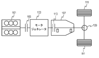
- FIG. 14 is a configuration diagram of a powertrain system of a conventional hybrid vehicle 100 using an engine and a motor generator disclosed in Patent Document 1.
- the output shaft of the engine 101 and the input shaft of the motor generator 103 are connected via a torque capacity variable clutch 105 (engine-side clutch).
- the output shaft of the motor generator 103 and the input shaft of the automatic transmission 107 are connected.
- a tire 111 is connected to the output shaft of the automatic transmission 107 via a differential gear 109.
- one of the variable torque capacity clutches that is responsible for power transmission in the automatic transmission 107 that varies depending on the shift state is used as the clutch 113 (transmission-side clutch).
- the automatic transmission 107 combines the power of the engine 101 input via the clutch 105 and the power input from the motor generator 103 and outputs the combined power to the tire 111.
- the vehicle hybrid system includes an engine mounted on the vehicle, a transmission mechanically connected to the engine, a drive shaft mechanically connected to the transmission, a rotation transmission unit connected to the drive shaft, A power connecting / disconnecting portion connected to the drive shaft via a rotation transmitting portion; a motor generator mechanically connected to the power connecting / disconnecting portion; and a motor transmitting power from the motor generator in a direction to drive the engine and a motor from the engine.
- a specific direction power transmission unit configured not to transmit power in a direction in which the generator is driven.
- Another vehicle hybrid system includes an engine mounted on a vehicle, a transmission mechanically connected to the engine, a drive shaft mechanically connected to the transmission, and a transmission output connected to the drive shaft.
- FIG. 1 is a conceptual diagram of a vehicle hybrid system according to the first embodiment.
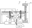
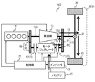
- FIG. 2 is a schematic configuration diagram of the vehicle hybrid system according to the first embodiment.
- FIG. 3 is a correlation characteristic diagram between the rotational speed of the motor generator and the torque in the vehicle hybrid system of the first embodiment.
- FIG. 4 is a schematic configuration diagram of the transmission of the vehicle hybrid system in the first embodiment.
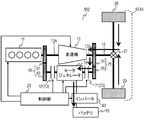
- FIG. 5 is a schematic configuration diagram showing the operation of the vehicle hybrid system in the first embodiment when the engine is started.
- FIG. 6 is a schematic configuration diagram showing an operation at the time of power running assist of the vehicle hybrid system in the first embodiment.
- FIG. 7A is a schematic configuration diagram showing an operation at the time of non-assist of the hybrid system for a vehicle in the first embodiment.
- FIG. 7B is a diagram showing a state of each part during operation of the vehicle hybrid system of the first embodiment.
- FIG. 8A is a schematic configuration diagram showing an operation during regeneration of the vehicle hybrid system in the first exemplary embodiment.
- FIG. 8B is a diagram showing a state of each part during operation of the vehicle hybrid system of the first embodiment.
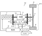
- FIG. 9 is a conceptual diagram of the vehicle hybrid system in the second embodiment.
- FIG. 10 is a schematic configuration diagram of the vehicle hybrid system according to the second embodiment.
- FIG. 11 is a schematic configuration diagram showing the operation at the time of shifting the operating point of the vehicle hybrid system in the second embodiment.
- FIG. 12 is a schematic configuration diagram showing an operation during electric driving of the vehicle hybrid system in the second embodiment.
- FIG. 13 is a schematic configuration diagram showing an operation during regeneration of the vehicle hybrid system in the second embodiment.
- FIG. 14 is a configuration diagram of a powertrain system of a conventional hybrid vehicle.
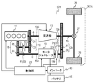
- (Embodiment 1) 1 and 2 are a conceptual diagram and a schematic configuration diagram of a hybrid system 501 for a vehicle according to Embodiment 1, respectively.
- a vehicle hybrid system 501 includes an engine 11 mounted on a vehicle 501 ⁇ / b> A, a transmission 13 mechanically connected to the engine 11, and a drive shaft mechanically connected to the transmission 13. 15, a motor generator 19 mechanically connected to the drive shaft 15 via the rotation transmission unit 25 and the power connection / disconnection unit 20, and a specific direction power transmission unit 22 mechanically connecting the motor generator 19 and the engine 11. And a rotation transmission unit 16 and a control unit 23 electrically connected to the motor generator 19 and the power connection / disconnection unit 20.
- the specific direction power transmission unit 22 transmits power from the motor generator 19 in the direction of driving the engine 11, but does not transmit power in the direction of driving the motor generator 19 from the engine 11.
- the vehicle hybrid system 501 has a configuration in which the transmission 13 and the motor generator 19 are arranged in parallel with respect to the output of the engine 11 and the drive shaft 15. Therefore, the control of the specific direction power transmission unit 22 and the power connection / disconnection unit 20 by the control unit 23 and the power running and regenerative control of the motor generator 19 enable the engine 11 to start, and the motor generator 19 is driven by the drive shaft 15. Therefore, highly efficient regeneration and power running avoiding loss of the transmission 13 are possible. As a result, high fuel efficiency can be obtained.
- the power of the engine 101 and the power input from the motor generator 103 are combined via the automatic transmission 107 and output to the tire 111.
- both the power of the engine 101 and the power of the motor generator 103 are input to the automatic transmission 107. Therefore, the loss of the automatic transmission 107 affects the power running and regeneration efficiency of the motor generator 103. For this reason, sufficient fuel efficiency cannot be obtained in combination with a continuously variable transmission or an automatic transmission equipped with a torque converter.
- the transmission 13 has an input side 13A and an output side 13B, and obtains the rotational speed of the output side 13B obtained by converting the rotational speed of the input side 13A.
- the input side 13 ⁇ / b> A of the transmission 13 is mechanically connected to the engine 11.
- the transmission 13 is a five-stage automatic transmission having a neutral stage to be cut and five speed stages of first speed, second speed, third speed, fourth speed, and fifth speed.
- the transmission 13 is not limited to a five-stage automatic transmission, but is a continuously variable automatic transmission or a manual transmission. Also good.
- the output side 13B of the transmission 13 is mechanically connected to the tire 29 via the drive shaft 15 and the differential gear 27.
- a gear 31 is coupled between the engine 11 and the input side 13A of the transmission 13.
- a gear 33 is engaged with the gear 31.
- a set of gears 31 and 33 constitutes the rotation transmission unit 16. The gear ratio between the gear 31 and the gear 33 is 1: 1.
- the one-way clutch 17 is used as the specific direction power transmission unit 22.
- the one-way clutch 17 has one end 17A and the other end 17B that can be mechanically fastened and disconnected from each other.
- One end 17 ⁇ / b> A of the one-way clutch 17 is mechanically connected to the gear 33 of the rotation transmission unit 16.
- the specific direction power transmission unit 22 is not electrically connected to the control unit 23, and the fastening and disconnection between the one end 17A and the other end 17B depends on the rotation direction and the number of rotations of the one end 17A and the other end 17B of the one-way clutch 17. Is done automatically.
- a gear 35 is mechanically connected to the other end 17 ⁇ / b> B of the one-way clutch 17.
- a gear 37 is engaged with the gear 35.
- a transmission unit that converts the rotational speed which is a set of gears 35 and 37, constitutes the rotation transmission unit 18.
- the gear ratio between the gear 35 and the gear 37 is 5: 1.
- the specific direction power transmission unit 22 is not limited to the one-way clutch 17, and may be a mechanical two-way clutch.
- the two-way clutch is set so that power is transmitted from the motor generator 19 in the direction of driving the engine 11, but power is not transmitted from the engine 11 in the direction of driving the motor generator 19.
- the one-way clutch 17 can sufficiently perform a necessary function. Therefore, it is preferable to use the one-way clutch 17 having a simple structure as the specific direction power transmission unit 22.
- the motor generator 19 is a biaxial motor generator having one end 19A and the other end 19B.
- One end 19 ⁇ / b> A of the motor generator 19 is mechanically connected to the gear 37. Therefore, one end 19 ⁇ / b> A of the motor generator 19 is mechanically connected to the engine 11 via the rotation transmission unit 18, the one-way clutch 17, and the rotation transmission unit 16.
- the clutch 21 is used as the power connection / disconnection part 20.
- the clutch 21 has one end 21A and the other end 21B that can be mechanically fastened and disconnected from each other.
- One end 21 ⁇ / b> A of the clutch 21 is mechanically connected to the other end 19 ⁇ / b> B of the motor generator 19.
- the power connection / disconnection part 20 is not limited to the clutch 21, and mechanical disconnection and engagement between the one end 21 ⁇ / b> A and the other end 21 ⁇ / b> B can be controlled by an external signal such as an electrically controlled two-way clutch. Anything is acceptable.
- the electrically controlled two-way clutch is suitable when a quick response is required.
- the gear 39 is mechanically connected to the other end 21B of the clutch 21.
- a gear 41 is engaged with the gear 39.
- the transmission unit that converts the rotational speed that is a set of the gears 39 and 41 constitutes the rotation transmission unit 25.
- the gear ratio between the gear 39 and the gear 41 is 1: 3.
- the gear 41 is configured to be coupled to the drive shaft 15. Therefore, the other end 19 ⁇ / b> B of the motor generator 19 is mechanically connected to the drive shaft 15 via the clutch 21 and the rotation transmission unit 25.
- the input side 13A of the transmission 13 is mechanically connected to one end 19A of the motor generator 19 via the one-way clutch 17, and the output side 13B of the transmission 13 is connected to the other of the motor generator 19 via the clutch 21. Mechanically connected to end 19B.
- the rotation transmission unit 18 and the rotation transmission unit 25 are both transmission units that change the rotation speed because the gear ratio is not 1: 1. Therefore, in the first embodiment, the motor generator 19 is connected to the power connection / disconnection part 20 (clutch 21) from the engine 11 through the specific direction power transmission part 22 (one-way clutch 17) to the connection. In this configuration, a speed change portion that converts the rotational speed is provided both before and after the drive shaft 15 is connected.
- the gear ratios of these transmission units may be appropriately determined according to the rotational characteristics of the motor generator 19, the engine 11, and the transmission 13. Further, the present invention is not limited to the above-described configuration.
- a configuration without a transmission unit may be used depending on the characteristics of the motor generator 19, the engine 11, and the transmission 13, a configuration without a transmission unit may be used. However, in practice, a configuration using a transmission unit is desirable in order to match these characteristics.
- the motor generator 19 can generate driving force by rotating the ends 19A and 19B by supplying electric power, and can generate electric power when an external rotational force is input to the end 19A or the end 19B. it can.
- FIG. 3 is a correlation characteristic diagram between the rotation speed and the torque generated when motor generator 19 in the first embodiment functions as a motor.
- the motor generator 19 is driven as a motor, at a specified voltage, a maximum torque of 25 N ⁇ m is generated when the rotational speed is less than 3000 rpm, and the torque gradually decreases when the rotational speed exceeds 3000 rpm, and between 3000 and 6000 rpm.
- a constant output is output, the rotational speed of 6000 rpm is the upper limit rotational speed, and the drive as a motor is stopped at 6000 rpm.
- the motor generator 19 can perform drive assist (power running) of the drive shaft 15 during traveling and regeneration during braking according to the traveling state of the vehicle 501A.
- the motor generator 19 is electrically connected to a battery 45 for storing regenerative power via an inverter 43.
- the engine 11, the transmission 13, the motor generator 19, the clutch 21, and the inverter 43 are electrically connected to the control unit 23.
- the control part 23 can take in the state of these apparatuses, and can control operation
- the control unit 23 includes a peripheral circuit including a microcomputer and a memory.
- the control unit 23 is also connected to other in-vehicle devices mounted on the vehicle 501A, and performs operations related to traveling of the vehicle 501A such as taking in an accelerator pedal signal or a brake pedal signal, for example.
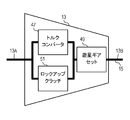
- FIG. 4 is a schematic configuration diagram of the transmission 13.
- an automatic transmission having a torque converter 47 with a lock-up clutch 51 is used as the transmission 13.
- the input from the engine 11 to the end 13 ⁇ / b> A is input to the torque converter 47, and then input to the planetary gear set 49 via the torque converter 47 at the subsequent stage.
- the input from the engine 11 is shifted and output from the end 13 ⁇ / b> B to the drive shaft 15.
- the control unit 23 controls the lockup clutch 51 to be engaged in order to reduce the loss of the torque converter 47.
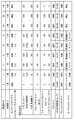
- Table 1 shows the gear ratios at the respective speeds of the transmission 13.
- the one-way clutch 17 is used that rotates only in the direction in which the rotation of the motor generator 19 is transmitted to the engine 11 and does not rotate in the direction in which the rotation of the engine 11 is transmitted to the motor generator 19. That is, when the rotational speed RE at point E (end 17B connected to the motor generator 19) in FIG. 2 is equal to or higher than the rotational speed RA at point A (end 17A connected to the engine 11), the one-way clutch 17 is engaged. When the ends 17A and 17B are connected and the rotation speed RE at the point E is less than the rotation speed RA at the point A, the one-way clutch 17 is disconnected between the ends 17A and 17B and idles.
- the clutch 21 has a configuration capable of controlling the engagement and disconnection between the ends 21A and 21B by an external signal.
- the control unit 23 controls the clutch 21.
- 5 to 7A are schematic configuration diagrams showing the operation of the vehicle hybrid system 501.
- FIG. 7B shows the state of each part from the start of the engine 11 to acceleration and constant speed running.
- the control unit 23 When the driver depresses the accelerator pedal and an acceleration command signal is issued, the control unit 23 receives the signal. As a result, since the one-way clutch 17 is engaged, the control unit 23 first drives the motor generator 19 to rotate and start the engine 11. At the same time, since the point A rotates, the driving force is transmitted to the drive shaft 15 through the torque converter 47 of the transmission 13, and finally the tire 29 is driven to start the vehicle 501A at a low speed.
- the torque required for starting the engine 11 is about 100 N ⁇ m when the engine 11 is a V6 engine of the 3 liter class, for example.
- the maximum torque of the motor generator 19 is 25 N ⁇ m as shown in FIG. Therefore, since the torque of the motor generator 19 is increased five times from the gear ratio of the gear 35 and the gear 37 and the engine 11 is rotated, a starting torque of 125 N ⁇ m can be applied to the engine 11. Therefore, the engine 11 can be sufficiently started by the vehicle hybrid system 501 of the first embodiment.
- control unit 23 drives the motor generator 19 with the clutch 21 disconnected when starting the engine 11.
- the control unit 23 performs fuel injection when the rotation of the engine 11 increases and the first or second cylinder reaches the compression top dead center, and the engine 11 is, for example, a direct injection type.
- the air-fuel mixture is burned by the spark plug to start the engine 11, and the motor generator 19 travels from the vehicle 501A traveling to the engine 11 traveling to the vehicle 501A.
- the state of the operation at this time is shown in FIG. Since the clutch 21 is disengaged, the driving force of the motor generator 19 is transmitted to the engine 11 and simultaneously input to the transmission 13 as shown by the thick arrows in FIG.
- the rotation speed of each part at this time is as shown in FIG. 7B.
- the engine 11 is started in the form of a push by the driving force of the motor generator 19 when the vehicle speed is between 0 and 2 km / h.
- the rotational speed RC (point C) of the motor generator 19 is in the range of 0 to 3000 rpm within the rotational range sufficient for starting the engine 11 and capable of generating the maximum torque.
- the rotational speed RB (point B) of the drive shaft 15 is uniquely determined by the fixed reduction ratio by the differential gear 27 and becomes 50 rpm.
- the number of stages of the transmission 13 is at the first speed for starting, and the gear ratio is 4: 1 from Table 1, and the rotational speed RA (point A) of the engine 11 is essentially the rotational speed RB at the point B.
- the torque converter 47 rotates with slip.
- the slip ratio at this time is 3.0, the rotation speed RA (point A) of the engine 11 is 600 rpm as a result.
- the motor generator 19 applies a torque to the transmission 13 via the rotation transmission unit 18, the one-way clutch 17, and the rotation transmission unit 16, and drives the tire 29 via the drive shaft 15 and the differential gear 27 to drive the vehicle 501A.
- the rotational speed RD at the point D driven from the drive shaft 15 via the rotation transmission unit 25 is 150 rpm based on the rotational speed RB at the point B and the gear ratio, and the rotational speed RC (point C) of the motor generator 19 is 3000 rpm.
- the clutch 21 is disengaged and no mismatch occurs.
- the engine 11 is started at a vehicle speed of about 0 to 2 km / h, and after shifting to running by the engine 11, the control unit 23 reduces the rotation speed of the motor generator 19. Then, by engaging the clutch 21, the output of the motor generator 19 is applied to the drive shaft 15 via the rotation transmission unit 25 and drives the tire 29.
- the rotational speed RB (point B) of the drive shaft 15 is used as a reference, and the rotational speed RD at the point D is determined as shown in FIG. 7B.
- the gear stage of the transmission 13 is still at the first speed, and the rotational speed RA at point A is 400 rpm.
- the lockup clutch 51 is still disconnected and the torque converter has a slip ratio of 2.
- the rotational speed RA (point A) of the engine 11 is 800 rpm.
- the one-way clutch 17 is disengaged because the rotational speed RE (60 rpm) at point E is lower than the rotational speed RA (800 rpm) at point A. Therefore, the engine 11 transmits the driving force to the drive shaft 15 via the transmission 13 while the motor generator 19 transmits the rotation to the drive shaft 15 together.
- the motor generator 19 can output a maximum torque of 25 N ⁇ m at a rotation speed of 300 rpm. However, the torque is tripled by the rotation transmission unit 25, and the drive shaft 15 is transmitted.
- the control unit 23 fastens the lock-up clutch 51 at medium and high speeds under the control of the lock-up clutch 51, eliminates the slip between the engine 11 and the transmission 13, and improves the efficiency.
- the control unit 23 disconnects the lock-up clutch 51, and uses the shock mitigation function of the torque converter 47 to mitigate slight vibrations and shift shocks caused by torsional vibrations of the drive system.
- the speed of the transmission 13 is changed to the fourth speed, the lockup clutch 51 is engaged, and the torque converter 47 is not slipped. Therefore, since the transmission ratio of the transmission 13 is 1: 1, the rotational speed RA (point A) of the engine 11 and the rotational speed RB (point B) of the drive shaft 15 are equal. In the first embodiment, the rotational speed is 1500 rpm. is there.
- the rotational speed RD at the point D is 4500 rpm based on the gear ratio of the rotation transmission unit 25 described above. Therefore, as shown in FIG. 3, the torque transmitted to the drive shaft 15 decreases as the speed increases.
- regenerative energy obtained by regeneration which will be described later, is reduced from the physical kinetic energy possessed by the vehicle 501A due to the overall transmission efficiency of the machine and electricity, and in the same way during the power running as well. Since energy is reduced due to the transmission efficiency, mechanical energy output from the tire is smaller than electrical energy stored in the battery. Therefore, from the viewpoint of energy balance between regeneration and power running, the control unit 23 sets the upper limit speed of power running lower than the upper limit speed of regeneration.
- control unit 23 disconnects the clutch 21 and stops the power running of the motor generator 19.
- the driving force at this time is transmitted from the engine 11 to the drive shaft 15 and the tire 29 via the transmission 13 as indicated by a thick arrow in FIG. 7A.
- the control unit 23 is a motor even when the vehicle speed is 60 km / h, such as during sudden acceleration.
- the assist of the drive shaft 15 by the generator 19 may be continued.
- the gear position of the transmission 13 is the fifth speed, and the gear ratio is 0.8: 1 (overdrive gear ratio) according to Table 1. Therefore, the rotational speed of the engine 11 is 2000 rpm, but the rotational speed of the drive shaft 15 is 2500 rpm. At this time, if the clutch 21 is engaged, the rotational speed RD at the point D is 7500 rpm from the gear ratio 3 of the rotation transmitting portion 25. Since this rotational speed value exceeds the upper limit rotational speed (6000 rpm) of the motor generator 19, the counter electromotive voltage exceeds the battery voltage, and an overvoltage is applied to the battery 45.
- the control unit 23 disconnects the clutch 21 when the vehicle speed exceeds a predetermined vehicle speed (80 km / h in the first embodiment) at which the back electromotive voltage exceeds a specified value. At the same time, the power running of the motor generator 19 is stopped. If the vehicle speed is equal to or lower than the predetermined vehicle speed, the clutch 21 is engaged and the motor generator 19 is powered.
- a predetermined vehicle speed 80 km / h in the first embodiment
- the predetermined vehicle speed is not limited to the vehicle speed at which the back electromotive voltage exceeds the battery voltage.
- the clutch 21 and the motor are controlled based on parameters such as efficiency reduction according to the rotational speed by field weakening control or the like. What is necessary is just to determine suitably according to the control state of the generator 19. FIG.
- the vehicle 501A is accelerated, but the controller 23 controls the hybrid system 501 for the vehicle based on the state shown in FIG.
- FIG. 8A is a schematic configuration diagram illustrating the operation of the vehicle hybrid system 501 during deceleration.
- FIG. 8B shows the state of each part of the vehicle hybrid system 501 when the vehicle 501A is decelerated.
- the state of the vehicle hybrid system 501 when the vehicle speed is 100 km / h is the same as that in FIG. 7B.
- the rotational speed RC (point C) of the motor generator 19 reaches 6000 rpm as shown in FIG. Become.
- the control unit 23 engages the clutch 21.
- the motor generator 19 is rotated by rotation from the drive shaft 15.
- the rotation speed of the engine 11 at this time is 1600 rpm from FIG. 8B.
- the rotation speed (6000 rpm) of the motor generator 19 is reduced to 1/5 by the rotation transmitting unit 18, the rotation speed RE at the point E of the end 17A of the one-way clutch 17 is 1200 rpm. Therefore, since the rotational speed RE is lower than the rotational speed of the engine 11, the one-way clutch 17 is disengaged and is not transmitting torque. Further, when the vehicle is decelerating in this way, the engine 11 does not need to output a driving force, so that fuel consumption is usually cut to improve fuel consumption, and the vehicle 501A is in an inertia running state called coasting.
- the flow of the driving force at this time is indicated by a thick arrow in FIG. 8A.
- the rotational force of the drive shaft 15 rotated by the tire 29 is input to the motor generator 19 via the rotation transmission unit 25 and the clutch 21, and the motor generator 19 generates regenerative power.
- This regenerative power is stored in the battery 45 via the inverter 43.
- the drive shaft 15 is also connected to the transmission 13.
- FIG. 8B when the vehicle speed is 80 km / h, the gear stage is 5th and the lockup clutch 51 is engaged.
- the rotation thus transmitted is also transmitted to the engine 11.
- the engine 11 since the engine 11 is performing fuel cut, it is simply rotated by the drive shaft 15.
- the basic operation is the same as the above-described operation at the vehicle speed of 80 km / h only by shifting the gear stage to the fourth speed.
- the transmission 13 becomes the third speed, and the lock-up clutch 51 is disconnected as a countermeasure against torsional resonance of the drive system, so that the torque converter 47 slips. Therefore, since the speed ratio of the drive shaft 15 is 1.5, if the rotational speed RB (point B) of the drive shaft 15 is 1000 rpm, the rotational speed RA (point A) of the engine 11 is 1500 rpm at the maximum. The rotational speed RA of the engine 11 decreases by the amount of slippage.
- the clutch 21 is engaged and the generation of regenerative power by the motor generator 19 continues.
- the rotation of the drive shaft 15 is input to the motor generator 19 via the rotation transmission unit 25 and the clutch 21, and is further transmitted to the one-way via the rotation transmission unit 18. It is transmitted to the clutch 17. Therefore, as long as the clutch 21 is in the engaged state, the rotation of the engine 11 can continue the fuel cut without stopping until the vehicle 501A stops. From this aspect, fuel consumption can be improved. For this reason, even when the vehicle 501A employs a brake system that uses the intake negative pressure of the engine 11 for boosting, the negative pressure can be maintained, and the safety of the vehicle 501A is improved.
- the control unit 23 sets the transmission 13 to neutral, disconnects the clutch 21, and stops the generation of regenerative power by the motor generator 19. This is the same as the state shown in FIG. As a result, the rotational speed RA at the point A and the rotational speed RE at the point E become equal at 0 rpm, and the one-way clutch 17 is ready for immediate engagement. However, since the drive shaft 15 is still rotating, the rotational speeds RB and RD at the points B and D are not 0 rpm.
- the control unit 23 maintains the state of 4 km / h, reaches the vehicle speed of 0 km / h, stops all the rotation speeds from point A to point E to 0 rpm.
- the control unit 23 may control the transmission 13 to be neutral so as to reduce the loss of the engine 11. Further, the control unit 23 may also control the clutch 21 to be disconnected so that the distance that can be coasted is further extended without causing the motor generator 19 to generate regenerative power.
- the rotational speed RA (point A) of the engine 11 is 0 rpm. Therefore, when it is necessary to restart the engine 11 by depressing the accelerator pedal, the motor generator 19 is rotated. Thus, since the rotational speed RA at point A is 0 rpm, the one-way clutch 17 is engaged, and the engine 11 can be restarted immediately by driving the motor generator 19.
- the control unit 23 sets the transmission 13 to neutral, engages the clutch 21, and regenerates electric power generated by the motor generator 19. You may control so that it may not take.
- the engine 11 is rotated from the drive shaft 15 via the motor generator 19 arranged in parallel with the transmission 13, and is rotated at a lower rotational speed than being rotated via the transmission 13. 11 can be kept low. Therefore, the distance that the vehicle 501A can coast can be extended. Further, the engine 11 continues to be rotated from the drive shaft 15 via the motor generator 19 while the vehicle 501A is traveling. Therefore, when it is necessary to restart the engine 11 by depressing the accelerator pedal, it is possible to immediately shift to running by the engine 11 simply by performing fuel injection and ignition, and also in a brake system using a negative pressure booster. The safety is improved.
- the control unit 23 disconnects the clutch 21 and turns off the motor generator 19, so that the reverse gear is selected by the transmission 13 and the engine 11 moves backward as in the case of a normal vehicle. do it.
- the control unit 23 may reverse the vehicle 501A by rotating the motor generator 19 reversely with the transmission 13 as neutral. In this case, since the motor generator 19 rotates in the reverse direction, the one-way clutch 17 runs idle. Further, if the motor generator 19 moves backward, the regenerative energy can be effectively utilized.
- control unit 23 When starting the engine 11, the control unit 23 cuts the power connecting / disconnecting unit 20 and powering the motor generator 19 to start the engine 11 via the specific direction power transmission unit 22.
- the transmission 13 is driven and the drive shaft 15 is rotated.
- control unit 23 fastens the power connection / disconnection unit 20 and then powers the motor generator 19 to rotate the drive shaft 15 via the power connection / disconnection unit 20 to propel the vehicle 501A.
- control unit 23 causes the motor generator 19 to generate regenerative power after fastening the power connection / disconnection unit 20.
- the transmission 13 and the motor generator 19 are mechanically arranged in parallel, and the clutch 21 on the output side 13B of the transmission 13 according to the powering and regeneration conditions as described above.
- the power running and regenerative stress on the motor generator 19 is directly transmitted to the drive shaft 15. Therefore, loss of the transmission 13 can be avoided, and a highly efficient vehicle hybrid system 501 can be obtained.
- FIGS. 9 and 10 are a conceptual diagram and a schematic configuration diagram, respectively, of the vehicle hybrid system 502 according to the second embodiment. 9 and 10, the same reference numerals are given to the same portions as those in the vehicle hybrid system 501 in the first embodiment shown in FIGS. 1 and 2.
- the vehicle hybrid system 502 includes an engine 11 mounted on a vehicle 501 ⁇ / b> A, a transmission 13 mechanically connected to the engine 11, and a drive shaft mechanically connected to the transmission 13. 15, a motor generator 19 mechanically connected to the drive shaft 15 via a transmission output side rotation transmission unit 75 and a power connection / disconnection unit 70, and a power connection / disconnection unit 72 mechanically connected to the motor generator 19.
- Transmission input side rotation transmission unit 66 for mechanically connecting power connection / disconnection unit 72 and engine 11, power connection / disconnection unit 70, motor generator 19, and control unit electrically connected to power connection / disconnection unit 72. 23.
- the hybrid system for a vehicle has a configuration in which the transmission 13 and the motor generator 19 are arranged in parallel with each other with respect to the output of the engine 11 and the drive shaft 15. Accordingly, the control of the power connection / disconnection unit 70 and the power connection / disconnection unit 72 by the control unit 23 and the power running and regenerative control of the motor generator 19 enable the engine 11 to start, and the motor generator 19 is attached to the drive shaft 15. Direct connection is possible. Therefore, highly efficient regeneration and power running avoiding the loss of the transmission 13 are possible, and as a result, high fuel efficiency is obtained.
- the vehicle hybrid system 502 of the second embodiment includes a power connection / disconnection unit 72 (instead of the specific direction power transmission unit 22 (one-way clutch 17) of the vehicle hybrid system 501 of the first embodiment.
- a clutch 67 has a configuration capable of controlling fastening and disconnection from the outside.
- the clutch 21 and the clutch 71 have the same configuration. Therefore, the clutch 67 and the clutch 71 can be independently engaged and disconnected by the control unit 23.
- At least one of the power connection / disconnection part 70 (clutch 71) and the power connection / disconnection part 72 (clutch 67) may be an electrically controlled two-way clutch.
- the idling and rotation direction can be selected by a signal from the outside, control of the hybrid system for a vehicle 502 according to various embodiments 2 described later can be easily realized with a simple configuration. .
- the vehicle hybrid system 502 according to the second embodiment does not include the rotation transmission unit 18 of the vehicle hybrid system 501 according to the first embodiment.
- the vehicle hybrid system 501 according to the first embodiment includes the rotation transmission unit 18 for the purpose of reducing the rotation speed because the one-way clutch 17 cannot follow at a high rotation speed.
- the vehicle hybrid system 502 includes a gear 31 and a gear 33 instead of the rotation transmission unit 16 including the gear 31 and the gear 33 of the vehicle hybrid system 501 according to the first embodiment. And a transmission input side rotation transmission unit 66 composed of the same gear 81 and gear 83 as the rotation transmission unit 16.
- the vehicle hybrid system 502 according to the second embodiment includes a gear 39 and a gear 41 instead of the rotation transmission unit 25 configured with the gear 39 and the gear 41 of the vehicle hybrid system 501 according to the first embodiment.
- All of these constitute a transmission unit having a function of converting the rotational speed.
- one of the rotation transmission units 25 and 75 may constitute a transmission unit, and the other may not have a rotation speed conversion function. That is, at least one of the period until the motor generator 19 is connected from the engine 11 via the power connection / disconnection part 70 and the period until the drive shaft 15 is connected from the motor generator 19 via the power connection / disconnection part 72.
- a transmission unit is provided.
- an optimal configuration may be selected as appropriate according to the rotational characteristics of the motor generator 19, the engine 11, and the transmission 13.
- a configuration without the transmission unit may be used. However, in practice, a configuration using the transmission unit is desirable in order to match these characteristics. .
- the basic operation of the vehicle hybrid system 502 of the second embodiment is equivalent to that of the first embodiment because the clutch 67 is provided in place of the one-way clutch 17 due to its configuration.
- the control unit 23 controls the clutch 67 so as to be the same as the engaged / disengaged state of the one-way clutch 17 of the vehicle hybrid system 501 of the first embodiment.
- vehicle hybrid system 502 The basic operation of the vehicle hybrid system 502 will be specifically described below.
- control unit 23 fastens the power connection / disconnection unit 70, disconnects the power connection / disconnection unit 72, and powers the motor generator 19. Then, the engine 11 is started, the transmission 13 is driven, and the drive shaft 15 is rotated.
- control unit 23 cuts the power connection / disconnection unit 70 and fastens the power connection / disconnection unit 72 and then causes the motor generator 19 to power-run, so that the motor generator 19 causes the drive shaft 15 to be connected via the power connection / disconnection unit 72.
- the vehicle is rotated to propel the vehicle 501A.
- the control unit 23 cuts the power connection / disconnection unit 70 and fastens the power connection / disconnection unit 72, and then causes the motor generator 19 to generate regenerative power.
- the vehicle hybrid system 502 can perform all the operations of engine start, power running, and regeneration by the motor generator 19 by performing the same basic operations as the vehicle hybrid system 501 of the first embodiment.
- high efficiency equivalent to that of the vehicle hybrid system 501 of the first embodiment can be obtained.
- FIG. 11 is a schematic configuration diagram showing an operation point operation of the vehicle hybrid system 502.
- the control unit 23 engages the clutch 67 and disengages the clutch 71 so that the rotation speed and torque at which the efficiency of the engine 11 is improved.
- the motor generator 19 is caused to generate power.
- the control unit 23 sends an output command to the engine 11 to output an output that is an output corresponding to the power generation amount of the motor generator 19.
- the engine 11 generates a torque obtained by adding the torque applied by the motor generator 19 for power generation to the torque commensurate with the running resistance, so that an operating point shift is performed in which the operating point of the load is shifted to the high load side. Is called. Therefore, high efficiency can be achieved as the entire vehicle hybrid system 502.
- the generated electric power is charged into the battery 45 via the inverter 43 and is used again for energy for power running.
- FIG. 12 is a schematic configuration diagram showing the operation of the vehicle 501 ⁇ / b> A during electric driving of the vehicle hybrid system 502.
- the control unit 23 disconnects the clutch 67, engages the clutch 71, and sets the transmission 13 to neutral, the motor generator 19 is driven, so that the vehicle 501A can be electrically driven.
- fuel consumption can be reduced accordingly.
- coasting driving assistance can be performed by performing the above-described control. Thereby, a coasting distance can be extended and it leads to reduction of fuel consumption.
- FIG. 13 is a schematic configuration diagram illustrating an operation during regeneration of the vehicle hybrid system according to the second embodiment of the present invention.
- the one-way clutch 17 is engaged during regeneration, depending on conditions, as in the vehicle speeds 40, 20, and 10 km / h shown in FIG. 8B during deceleration.
- the rotation of the one-way clutch 17 is thereby transmitted to the engine 11, so that a loss is generated as the engine 11 is rotated.
- the controller 23 disconnects the clutch 67, engages the clutch 71, and sets the transmission 13 to neutral, whereby all the rotation from the tire 29 is input to the motor generator 19. You can make it. As a result, loss of the engine 11 can be avoided, so that highly efficient regeneration can be achieved accordingly.
- the clutch 67 needs to be disengaged and engaged, and accordingly, the control is complicated, but the vehicle hybrid according to the first embodiment.
- the rotation transmission unit 18 of the system 501 is unnecessary and the configuration is simplified.
- the operating point shift, the electric running, and the highly efficient regenerative operation can be performed. Is possible.
- the transmission 13 and the motor generator 19 are mechanically arranged in parallel, and are connected to the input side 13A and the output side 13B of the transmission 13, respectively, according to power running and regeneration conditions.
- the clutch 67 and the clutch 71 By controlling the engagement and disconnection of the clutch 67 and the clutch 71, the power running and regenerative stress to the motor generator 19 are directly transmitted. Therefore, loss of the transmission 13 can be avoided, and a highly efficient vehicle hybrid system 502 can be obtained.
- a gear is used as each rotation transmission unit.
- a pulley, a belt, or a chain may be used. However, since these may slip over time, it is more efficient to use gears.
- the specific direction power transmission unit 22 and the power connection / disconnection unit 72 are mechanically connected to a connection portion between one end of the engine 11 and the transmission 13. However, it may be connected to the other end of the engine 11 or a dedicated output extraction portion may be provided separately.
- the motor generator 19 having a double-shaft structure having the shafts 19A and 19B, that is, the two-shaft structure is used, but the motor generator 19 has a single-shaft structure. May be.
- a biaxial structure can be obtained by providing a rotation transmission portion including a gear or the like that divides rotation at the tip of one axis.
- the vehicle hybrid system according to the present invention can achieve high efficiency with a configuration in which a motor generator is juxtaposed with respect to a transmission, it is particularly useful as a hybrid system for a vehicle using an engine and a motor generator.
Abstract
Description
図1と図2はそれぞれ実施の形態1における車両用ハイブリッドシステム501の概念図と概略構成図である。 (Embodiment 1)
1 and 2 are a conceptual diagram and a schematic configuration diagram of a

図9と図10はそれぞれ実施の形態2における車両用ハイブリッドシステム502の概念図と概略構成図である。図9と図10において、図1と図2に示す実施の形態1における車両用ハイブリッドシステム501と同じ部分には同じ参照符号を付す。 (Embodiment 2)
FIGS. 9 and 10 are a conceptual diagram and a schematic configuration diagram, respectively, of the
13 変速機
15 駆動軸
17 ワンウェイクラッチ
18 回転伝達部
19 モータジェネレータ
20 動力断接部
21,67,71 クラッチ
22 特定方向動力伝達部
23 制御部
25 回転伝達部
66 変速機入力側回転伝達部
70 動力断接部(第1動力断接部)
72 動力断接部(第2動力断接部)
75 変速機出力側回転伝達部
501,502 車両用ハイブリッドシステム
501A 車両 DESCRIPTION OF
72 Power connection / disconnection (second power connection / disconnection)
75 Transmission output side
Claims (9)
- 車両に搭載されるエンジンと、
前記エンジンと機械的に接続される変速機と、
前記変速機と機械的に接続される駆動軸と、
前記駆動軸に接続された回転伝達部と、
前記駆動軸に前記回転伝達部を介して接続された動力断接部と、
前記動力断接部に機械的に接続されたモータジェネレータと、
前記モータジェネレータから前記エンジンを駆動する方向に動力を伝達しかつ前記エンジンから前記モータジェネレータを駆動する方向には動力を伝達しないように構成された特定方向動力伝達部と、
前記モータジェネレータと前記動力断接部と電気的に接続される制御部と、
を備えた車両用ハイブリッドシステム。 An engine mounted on the vehicle,
A transmission mechanically connected to the engine;
A drive shaft mechanically connected to the transmission;
A rotation transmission unit connected to the drive shaft;
A power connection / disconnection portion connected to the drive shaft via the rotation transmission portion;
A motor generator mechanically connected to the power connection / disconnection part;
A specific direction power transmission unit configured to transmit power in the direction of driving the engine from the motor generator and not transmit power in the direction of driving the motor generator from the engine;
A control unit electrically connected to the motor generator and the power connection / disconnection unit;
Hybrid system for vehicles equipped with - 前記制御部は、
前記エンジンを始動する際に、前記動力断接部を切断した状態で前記モータジェネレータを力行させることで、前記モータジェネレータに前記特定方向動力伝達部を介して前記エンジンを始動させるとともに、前記変速機を駆動して前記駆動軸を回転させ、
前記動力断接部を締結した状態で前記モータジェネレータを力行させることで、前記モータジェネレータに前記動力断接部を介して前記駆動軸を回転させて前記車両を推進させ、
前記車両を減速する際に、前記動力断接部を締結した状態で、前記モータジェネレータを回生させる、
ように構成された、請求項1に記載の車両用ハイブリッドシステム。 The controller is
When starting the engine, by causing the motor generator to power while the power connection / disconnection portion is disconnected, the motor generator starts the engine via the specific direction power transmission unit, and the transmission To rotate the drive shaft,
By powering the motor generator in a state where the power connection / disconnection part is fastened, the motor generator is propelled by rotating the drive shaft via the power connection / disconnection part,
When decelerating the vehicle, the motor generator is regenerated in a state where the power connection / disconnection portion is fastened.
The vehicle hybrid system according to claim 1, configured as described above. - 前記特定方向動力伝達部はワンウェイクラッチである、請求項1に記載の車両用ハイブリッドシステム。 The vehicle hybrid system according to claim 1, wherein the specific direction power transmission unit is a one-way clutch.
- 前記動力断接部は電気制御式ツーウェイクラッチである、請求項1に記載の車両用ハイブリッドシステム。 The hybrid system for a vehicle according to claim 1, wherein the power connection / disconnection part is an electrically controlled two-way clutch.
- 前記エンジンから前記特定方向動力伝達部を介して前記モータジェネレータを接続するまでの間と、前記モータジェネレータから前記動力断接部を介して前記駆動軸を接続するまでの間との少なくとも一方に設けられた変速部をさらに備えた、請求項1に記載の車両用ハイブリッドシステム。 Provided in at least one of the period from the engine until the motor generator is connected via the specific direction power transmission unit and the period from the motor generator to the drive shaft connected via the power connection / disconnection unit. The hybrid system for a vehicle according to claim 1, further comprising a transmission unit that is provided.
- 車両に搭載されるエンジンと、
前記エンジンと機械的に接続された変速機と、
前記変速機と機械的に接続された駆動軸と、
前記駆動軸に接続された変速機出力側回転伝達部と、
前記駆動軸に前記変速機出力側回転伝達部を介して機械的に接続された第1動力断接部と、
前記第1動力断接部に機械的に接続されたモータジェネレータと、
前記モータジェネレータと機械的に接続された第2動力断接部と。
前記第2動力断接部と前記エンジンとを機械的に接続する変速機入力側回転伝達部と、
前記第1動力断接部と前記モータジェネレータと前記第2動力断接部とに電気的に接続される制御部と、
を備えた車両用ハイブリッドシステム。 An engine mounted on the vehicle,
A transmission mechanically connected to the engine;
A drive shaft mechanically connected to the transmission;
A transmission output side rotation transmission unit connected to the drive shaft;
A first power connection / disconnection portion mechanically connected to the drive shaft via the transmission output side rotation transmission portion;
A motor generator mechanically connected to the first power connection / disconnection portion;
A second power connection / disconnection portion mechanically connected to the motor generator;
A transmission input side rotation transmission portion that mechanically connects the second power connection / disconnection portion and the engine;
A control unit electrically connected to the first power connection / disconnection unit, the motor generator, and the second power connection / disconnection unit;
Hybrid system for vehicles equipped with - 前記制御部は、
前記エンジンを始動する際に、前記第1動力断接部を締結し前記第2動力断接部を切断したうえで、前記モータジェネレータを力行させることで、前記第1動力断接部を介して、前記エンジンを始動させるとともに、前記変速機を駆動し、前記駆動軸を回転させ、
前記第1動力断接部を切断し前記第2動力断接部を締結した状態で、前記モータジェネレータを力行させることで、前記モータジェネレータに前記第2動力断接部を介して前記駆動軸を回転させて前記車両を推進させ、
前記車両を減速する際に、前記第1動力断接部を切断し前記第2動力断接部を締結した状態で、前記モータジェネレータを回生させる、
ように構成された、請求項6に記載の車両用ハイブリッドシステム。 The controller is
When starting the engine, the first power connecting / disconnecting portion is fastened and the second power connecting / disconnecting portion is disconnected, and then the motor generator is powered, via the first power connecting / disconnecting portion. , Starting the engine, driving the transmission, rotating the drive shaft,
In a state where the first power connection / disconnection part is cut and the second power connection / disconnection part is fastened, the motor generator is caused to power-run, thereby causing the motor generator to drive the drive shaft via the second power connection / disconnection part. Rotate to propel the vehicle,
When decelerating the vehicle, the motor generator is regenerated in a state where the first power connection / disconnection portion is cut and the second power connection / disconnection portion is fastened.
The vehicle hybrid system according to claim 6, configured as described above. - 前記第1動力断接部と前記第2動力断接部の少なくとも一方は電気制御式ツーウェイクラッチである、請求項6に記載の車両用ハイブリッドシステム。 The vehicle hybrid system according to claim 6, wherein at least one of the first power connection / disconnection part and the second power connection / disconnection part is an electrically controlled two-way clutch.
- 前記エンジンから前記第1動力断接部を介して前記モータジェネレータを接続するまでの間と、前記モータジェネレータから前記第2動力断接部を介して前記駆動軸を接続するまでの間との少なくとも一方に設けられた変速部をさらに備えた、請求項6に記載の車両用ハイブリッドシステム。 At least between the time until the motor generator is connected from the engine via the first power connection / disconnection portion and the time until the drive shaft is connected from the motor generator via the second power connection / disconnection portion. The hybrid system for a vehicle according to claim 6, further comprising a transmission portion provided on one side.
Priority Applications (3)
| Application Number | Priority Date | Filing Date | Title |
|---|---|---|---|
| EP15751997.6A EP3109111B1 (en) | 2014-02-20 | 2015-01-13 | Vehicle hybrid system |
| US15/032,657 US10046753B2 (en) | 2014-02-20 | 2015-01-13 | Vehicle hybrid system |
| JP2016503955A JP6573201B2 (en) | 2014-02-20 | 2015-01-13 | Hybrid system for vehicles |
Applications Claiming Priority (2)
| Application Number | Priority Date | Filing Date | Title |
|---|---|---|---|
| JP2014030316 | 2014-02-20 | ||
| JP2014-030316 | 2014-02-20 |
Publications (1)
| Publication Number | Publication Date |
|---|---|
| WO2015125407A1 true WO2015125407A1 (en) | 2015-08-27 |
Family
ID=53877936
Family Applications (1)
| Application Number | Title | Priority Date | Filing Date |
|---|---|---|---|
| PCT/JP2015/000107 WO2015125407A1 (en) | 2014-02-20 | 2015-01-13 | Vehicle hybrid system |
Country Status (4)
| Country | Link |
|---|---|
| US (1) | US10046753B2 (en) |
| EP (1) | EP3109111B1 (en) |
| JP (1) | JP6573201B2 (en) |
| WO (1) | WO2015125407A1 (en) |
Cited By (1)
| Publication number | Priority date | Publication date | Assignee | Title |
|---|---|---|---|---|
| JP2017094854A (en) * | 2015-11-20 | 2017-06-01 | トヨタ自動車株式会社 | Vehicle drive apparatus |
Families Citing this family (14)
| Publication number | Priority date | Publication date | Assignee | Title |
|---|---|---|---|---|
| FR3019791B1 (en) * | 2014-04-11 | 2017-11-03 | Renault Sas | METHOD FOR CONTROLLING A HYBRID TRANSMISSION FOR A MOTOR VEHICLE WITH ACCOUNT OF TRANSITION INTERRUPTIONS BETWEEN CINEMATIC MODES |
| CN106608176A (en) * | 2016-10-26 | 2017-05-03 | 联合汽车电子有限公司 | Hybrid electric vehicle power system and power transmission method thereof |
| CN106608178A (en) * | 2016-10-26 | 2017-05-03 | 联合汽车电子有限公司 | A power system for a hybrid vehicle and a power transmission method thereof |
| CN106608175A (en) * | 2016-10-26 | 2017-05-03 | 联合汽车电子有限公司 | Hybrid electric vehicle power system and power transmission method thereof |
| JP6669058B2 (en) * | 2016-12-27 | 2020-03-18 | トヨタ自動車株式会社 | Vehicle drive system |
| DE102017208249A1 (en) * | 2017-05-16 | 2018-11-22 | Volkswagen Aktiengesellschaft | Motor vehicle drive train with freewheel having gear |
| DE102018201370B4 (en) * | 2018-01-30 | 2023-10-26 | Magna powertrain gmbh & co kg | Drive train for a hybrid vehicle |
| CN109080429A (en) * | 2018-09-26 | 2018-12-25 | 特百佳动力科技有限公司 | Commercial Vehicular hybrid power system, control method and commercial vehicle |
| CN109649149B (en) * | 2019-01-16 | 2024-02-09 | 无锡商业职业技术学院 | Hybrid power transmission system capable of recovering double motors simultaneously under energy overflow working condition |
| CN111634281A (en) * | 2019-10-25 | 2020-09-08 | 长城汽车股份有限公司 | Energy recovery control method and device for vehicle |
| GB2594280B (en) * | 2020-04-21 | 2022-10-05 | Jaguar Land Rover Ltd | Apparatus and method for controlling an electric machine |
| GB2594286B (en) * | 2020-04-21 | 2022-07-20 | Jaguar Land Rover Ltd | Apparatus and method for controlling an electric machine |
| CN111775685B (en) * | 2020-07-14 | 2022-02-18 | 中国第一汽车股份有限公司 | Driving system of rear-drive hybrid power vehicle |
| CN116201865A (en) * | 2021-11-30 | 2023-06-02 | 通用汽车环球科技运作有限责任公司 | Hydraulically actuated clutch system and control logic for a torque converter assembly |
Citations (6)
| Publication number | Priority date | Publication date | Assignee | Title |
|---|---|---|---|---|
| JPH0195944A (en) * | 1987-10-07 | 1989-04-14 | Aisin Aw Co Ltd | Power transmitting gear for hybrid vehicle |
| JP2004122925A (en) * | 2002-10-02 | 2004-04-22 | Kokusan Denki Co Ltd | Hybrid motorcycle and its power transmission device |
| JP2005271669A (en) * | 2003-04-16 | 2005-10-06 | Tai-Her Yang | Electric backward movement auxiliary system for motorcycle driven by engine |
| JP2011501713A (en) * | 2007-10-10 | 2011-01-13 | イエフペ エネルジ ヌヴェル | Travel drive apparatus having a plurality of transmission paths for a hybrid vehicle and method using the same |
| JP2012240623A (en) * | 2011-05-24 | 2012-12-10 | Jatco Ltd | Hybrid drive device |
| US20140011631A1 (en) * | 2012-07-03 | 2014-01-09 | Ferrari S.P.A. | Automatic manual transmission for a hybrid car provided with an internal combustion engine and with an electrical machine |
Family Cites Families (16)
| Publication number | Priority date | Publication date | Assignee | Title |
|---|---|---|---|---|
| US5549524A (en) * | 1994-10-03 | 1996-08-27 | Yang; Tai-Her | Multiple functioned combined power system |
| JP3441198B2 (en) * | 1994-10-25 | 2003-08-25 | 株式会社エクォス・リサーチ | Hybrid vehicle |
| JP3890803B2 (en) | 1999-04-12 | 2007-03-07 | トヨタ自動車株式会社 | Power transmission device for hybrid vehicle |
| JP3411522B2 (en) * | 1999-04-13 | 2003-06-03 | ダイハツ工業株式会社 | Motor assist drive for automobile |
| JP4499084B2 (en) * | 2000-03-10 | 2010-07-07 | 日立オートモティブシステムズ株式会社 | Automatic transmission for automobile and automobile using the same |
| JP3677733B2 (en) * | 2000-04-06 | 2005-08-03 | ジヤトコ株式会社 | Parallel hybrid vehicle |
| JP2004357443A (en) * | 2003-05-30 | 2004-12-16 | Toyoda Mach Works Ltd | Storage means regeneration circuit, vehicle drive regeneration device and vehicle |
| JP4341611B2 (en) | 2005-11-09 | 2009-10-07 | 日産自動車株式会社 | Engine restart control device for hybrid vehicle |
| JP5456263B2 (en) * | 2007-05-02 | 2014-03-26 | 日産自動車株式会社 | Drive control apparatus for hybrid vehicle |
| US7972235B2 (en) * | 2007-10-11 | 2011-07-05 | GM Global Technology Operations LLC | Hybrid powertrain system having selectively connectable engine, motor/generator, and transmission |
| JP5169433B2 (en) | 2008-04-21 | 2013-03-27 | 日産自動車株式会社 | Power generation control method for hybrid vehicle |
| JP2012531353A (en) * | 2009-06-24 | 2012-12-10 | フィスカー オートモーティブ インコーポレイテッド | Drive configuration for high hybrid series / parallel high-speed motor drive system |
| JP2011131829A (en) * | 2009-12-25 | 2011-07-07 | Mitsubishi Fuso Truck & Bus Corp | Controller for hybrid electric vehicle |
| JP2011255706A (en) * | 2010-06-04 | 2011-12-22 | Honda Motor Co Ltd | Drive device for hybrid vehicle |
| JP5648428B2 (en) * | 2010-11-02 | 2015-01-07 | アイシン精機株式会社 | Transmission device for hybrid vehicle |
| JP5467197B2 (en) * | 2011-05-24 | 2014-04-09 | ジヤトコ株式会社 | Hybrid drive device |
-
2015
- 2015-01-13 WO PCT/JP2015/000107 patent/WO2015125407A1/en active Application Filing
- 2015-01-13 JP JP2016503955A patent/JP6573201B2/en active Active
- 2015-01-13 US US15/032,657 patent/US10046753B2/en active Active
- 2015-01-13 EP EP15751997.6A patent/EP3109111B1/en active Active
Patent Citations (6)
| Publication number | Priority date | Publication date | Assignee | Title |
|---|---|---|---|---|
| JPH0195944A (en) * | 1987-10-07 | 1989-04-14 | Aisin Aw Co Ltd | Power transmitting gear for hybrid vehicle |
| JP2004122925A (en) * | 2002-10-02 | 2004-04-22 | Kokusan Denki Co Ltd | Hybrid motorcycle and its power transmission device |
| JP2005271669A (en) * | 2003-04-16 | 2005-10-06 | Tai-Her Yang | Electric backward movement auxiliary system for motorcycle driven by engine |
| JP2011501713A (en) * | 2007-10-10 | 2011-01-13 | イエフペ エネルジ ヌヴェル | Travel drive apparatus having a plurality of transmission paths for a hybrid vehicle and method using the same |
| JP2012240623A (en) * | 2011-05-24 | 2012-12-10 | Jatco Ltd | Hybrid drive device |
| US20140011631A1 (en) * | 2012-07-03 | 2014-01-09 | Ferrari S.P.A. | Automatic manual transmission for a hybrid car provided with an internal combustion engine and with an electrical machine |
Cited By (1)
| Publication number | Priority date | Publication date | Assignee | Title |
|---|---|---|---|---|
| JP2017094854A (en) * | 2015-11-20 | 2017-06-01 | トヨタ自動車株式会社 | Vehicle drive apparatus |
Also Published As
| Publication number | Publication date |
|---|---|
| EP3109111A1 (en) | 2016-12-28 |
| JP6573201B2 (en) | 2019-09-11 |
| US20160272187A1 (en) | 2016-09-22 |
| JPWO2015125407A1 (en) | 2017-03-30 |
| US10046753B2 (en) | 2018-08-14 |
| EP3109111B1 (en) | 2019-08-28 |
| EP3109111A4 (en) | 2017-03-15 |
Similar Documents
| Publication | Publication Date | Title |
|---|---|---|
| JP6573201B2 (en) | Hybrid system for vehicles | |
| JP6301991B2 (en) | Hybrid vehicle system | |
| US9527375B2 (en) | Powertrain with transmission-based motor/generator for engine starting and regenerative braking modes | |
| US6416437B2 (en) | Transmission for hybrid electric vehicle | |
| US7240751B2 (en) | Dual rotor motor for a hybrid vehicle transmission | |
| KR101650599B1 (en) | Flywheel module as well as method for energy storage and delivery in the flywheel module | |
| US8251166B2 (en) | Hybrid powertrain with assisted starting and method of starting an engine | |
| US8512189B2 (en) | Hybrid powertrain with compound-split EVT drive axle and electric drive axle | |
| JP2007331632A (en) | Vehicle driving device and system | |
| US8226516B2 (en) | Electric torque converter with dual-driven main pump | |
| US9937782B2 (en) | All wheel drive system for hybrid vehicle | |
| JP7372088B2 (en) | hybrid vehicle system | |
| US10933862B2 (en) | Vehicle control system | |
| JP6817767B2 (en) | Control device and control method for hybrid vehicle system | |
| KR100836360B1 (en) | power train structure of a hybrid vehicle | |
| JP2010083230A (en) | Hybrid drive device | |
| US20130297107A1 (en) | Traction control system for a hybrid vehicle | |
| CN103009994A (en) | Power coupling device and transmission system of hybrid power vehicle | |
| CN107554274B (en) | Multi-mode power transmission structure of hybrid electric vehicle | |
| JP2008044517A (en) | Power transmission system | |
| JP6270416B2 (en) | Vehicle control device | |
| CN110962579A (en) | Single-planet-row series-parallel system and hybrid power vehicle | |
| CN104786823B (en) | Multi-gear series-parallel hybrid power system | |
| JP2011057194A (en) | Transmission with motor for hybrid automobile | |
| KR101123474B1 (en) | Power transmitting apparatus of hybird vehicles |
Legal Events
| Date | Code | Title | Description |
|---|---|---|---|
| 121 | Ep: the epo has been informed by wipo that ep was designated in this application |
Ref document number: 15751997 Country of ref document: EP Kind code of ref document: A1 |
|
| REEP | Request for entry into the european phase |
Ref document number: 2015751997 Country of ref document: EP |
|
| WWE | Wipo information: entry into national phase |
Ref document number: 2015751997 Country of ref document: EP |
|
| WWE | Wipo information: entry into national phase |
Ref document number: 15032657 Country of ref document: US |
|
| ENP | Entry into the national phase |
Ref document number: 2016503955 Country of ref document: JP Kind code of ref document: A |
|
| NENP | Non-entry into the national phase |
Ref country code: DE |