WO2015121980A1 - オーバーヘッド型画像読取装置、画像処理方法、および、プログラム - Google Patents
オーバーヘッド型画像読取装置、画像処理方法、および、プログラム Download PDFInfo
- Publication number
- WO2015121980A1 WO2015121980A1 PCT/JP2014/053501 JP2014053501W WO2015121980A1 WO 2015121980 A1 WO2015121980 A1 WO 2015121980A1 JP 2014053501 W JP2014053501 W JP 2014053501W WO 2015121980 A1 WO2015121980 A1 WO 2015121980A1
- Authority
- WO
- WIPO (PCT)
- Prior art keywords
- finger
- region
- contour
- medium
- area
- Prior art date
- Legal status (The legal status is an assumption and is not a legal conclusion. Google has not performed a legal analysis and makes no representation as to the accuracy of the status listed.)
- Ceased
Links
Images











Classifications
-
- H—ELECTRICITY
- H04—ELECTRIC COMMUNICATION TECHNIQUE
- H04N—PICTORIAL COMMUNICATION, e.g. TELEVISION
- H04N1/00—Scanning, transmission or reproduction of documents or the like, e.g. facsimile transmission; Details thereof
- H04N1/04—Scanning arrangements, i.e. arrangements for the displacement of active reading or reproducing elements relative to the original or reproducing medium, or vice versa
- H04N1/19—Scanning arrangements, i.e. arrangements for the displacement of active reading or reproducing elements relative to the original or reproducing medium, or vice versa using multi-element arrays
- H04N1/195—Scanning arrangements, i.e. arrangements for the displacement of active reading or reproducing elements relative to the original or reproducing medium, or vice versa using multi-element arrays the array comprising a two-dimensional [2D] array
- H04N1/19594—Scanning arrangements, i.e. arrangements for the displacement of active reading or reproducing elements relative to the original or reproducing medium, or vice versa using multi-element arrays the array comprising a two-dimensional [2D] array using a television camera or a still video camera
-
- H—ELECTRICITY
- H04—ELECTRIC COMMUNICATION TECHNIQUE
- H04N—PICTORIAL COMMUNICATION, e.g. TELEVISION
- H04N1/00—Scanning, transmission or reproduction of documents or the like, e.g. facsimile transmission; Details thereof
- H04N1/38—Circuits or arrangements for blanking or otherwise eliminating unwanted parts of pictures
-
- H—ELECTRICITY
- H04—ELECTRIC COMMUNICATION TECHNIQUE
- H04N—PICTORIAL COMMUNICATION, e.g. TELEVISION
- H04N23/00—Cameras or camera modules comprising electronic image sensors; Control thereof
- H04N23/60—Control of cameras or camera modules
- H04N23/61—Control of cameras or camera modules based on recognised objects
- H04N23/611—Control of cameras or camera modules based on recognised objects where the recognised objects include parts of the human body
-
- H—ELECTRICITY
- H04—ELECTRIC COMMUNICATION TECHNIQUE
- H04N—PICTORIAL COMMUNICATION, e.g. TELEVISION
- H04N2201/00—Indexing scheme relating to scanning, transmission or reproduction of documents or the like, and to details thereof
- H04N2201/04—Scanning arrangements
- H04N2201/0402—Arrangements not specific to a particular one of the scanning methods covered by groups H04N1/04 - H04N1/207
- H04N2201/0434—Arrangements not specific to a particular one of the scanning methods covered by groups H04N1/04 - H04N1/207 specially adapted for scanning pages of a book
-
- H—ELECTRICITY
- H04—ELECTRIC COMMUNICATION TECHNIQUE
- H04N—PICTORIAL COMMUNICATION, e.g. TELEVISION
- H04N2201/00—Indexing scheme relating to scanning, transmission or reproduction of documents or the like, and to details thereof
- H04N2201/04—Scanning arrangements
- H04N2201/0402—Arrangements not specific to a particular one of the scanning methods covered by groups H04N1/04 - H04N1/207
- H04N2201/0436—Scanning a picture-bearing surface lying face up on a support
Definitions
- the present invention relates to an overhead image reading apparatus, an image processing method, and a program.
- an image processing apparatus that detects a skin color area in a photographed image, detects a circumscribed rectangle circumscribing the outline of the skin color area, and recognizes it as a finger area when the circumscribed rectangle touches the outer edge of the photographed image (See Patent Document 2).
- an image reading apparatus that detects, as a finger image, a line in which pixels having a luminance lower than a set value are connected for each line including a line at a position corresponding to the edge of the document.
- Patent Document 1 since the finger is detected based on the brightness or skin color inside the medium, when the skin color area exists inside the medium, or the user wears gloves In such a case, there is a problem that a finger detection error occurs.
- the present invention has been made in view of the above-described problems.
- the contour of the medium (book) is extracted from the captured image, and the contour of the entire hand (glove) holding the medium from the color information outside both ends of the medium contour. It is an object to provide an overhead image reading apparatus, an image processing method, and a program.
- the program according to the present invention includes an image acquisition step of causing the overhead image reading apparatus to read a medium by an image reading unit and acquiring the read image, and color information outside the medium area in the read image. And a hand region extracting step for extracting a hand region included in the read image.
- the finger erasing operation is not required by automatically erasing the finger after imaging, so that the user's manual operation is reduced and the work efficiency is increased.
- FIG. 1 is a hardware configuration diagram illustrating an example of a schematic configuration of an overhead image reading apparatus.
- FIG. 2 is a diagram illustrating an example of the configuration of the control unit according to the present embodiment.
- FIG. 3 is a hardware configuration diagram illustrating an example of a configuration of the overhead image reading apparatus viewed from the front.
- FIG. 4 is a hardware configuration diagram illustrating an example of a configuration of the overhead image reading apparatus viewed from the side.
- FIG. 5 is a functional block diagram illustrating an example of the configuration of the overhead image reading apparatus.
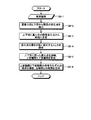
- FIG. 6 is a flowchart showing an example of processing in the overhead image reading apparatus of the present embodiment.
- FIG. 7 is a flowchart showing an example of the media contour extraction process in the present embodiment.
- FIG. 1 is a hardware configuration diagram illustrating an example of a schematic configuration of an overhead image reading apparatus.
- FIG. 2 is a diagram illustrating an example of the configuration of the control unit according to the present embodiment.
- FIG. 3 is a hardware configuration diagram
- FIG. 8 is a diagram illustrating an example of change point detection in the present embodiment.
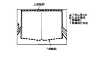
- FIG. 9 is a diagram illustrating an example of upper contour / lower contour generation in the present embodiment.
- FIG. 10 is a diagram illustrating an example of left contour / right contour generation in the present embodiment.
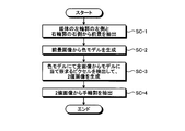
- FIG. 11 is a flowchart illustrating an example of a hand contour extraction process in the present embodiment.
- FIG. 12 is a diagram illustrating an example of foreground extraction in the present embodiment.
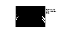
- FIG. 13 is a diagram illustrating an example of binary image generation in the present embodiment.
- FIG. 14 is a diagram illustrating an example of hand contour extraction in the present embodiment.
- FIG. 15 is a flowchart illustrating an example of the finger area extraction process in the present embodiment.
- FIG. 16 is a diagram illustrating an example of finger area extraction in the present embodiment.
- FIG. 17 is a flowchart illustrating an example of the finger area extraction process in the present embodiment.
- FIG. 18 is a diagram illustrating an example of color change point extraction in the present embodiment.
- FIG. 19 is a diagram illustrating an example of color model construction in the present embodiment.
- FIG. 20 is a flowchart showing an example of the media contour extraction process in the present embodiment.
- FIG. 21 is a diagram illustrating an example of the center of gravity analysis in the present embodiment.
- FIG. 22 is a diagram illustrating an example of width analysis in the present embodiment.
- FIG. 23 is a diagram illustrating an example of width analysis in the present embodiment.
- FIG. 24 is a flowchart illustrating an example of recovery processing in the present embodiment.
- FIG. 25 is a diagram illustrating an example of highlighting in the present embodiment.
- FIG. 26 is a diagram showing an example of point display in the present embodiment.
- FIG. 27 is a
- FIG. 1 is a hardware configuration diagram illustrating an example of a schematic configuration of the overhead image reading apparatus 100.
- FIG. 3 is a hardware configuration diagram illustrating an example of the configuration of the overhead image reading apparatus 100 as viewed from the front.
- FIG. 4 is a hardware configuration diagram illustrating an example of the configuration of the overhead image reading apparatus 100 as viewed from the side.
- FIG. 5 is a functional block diagram illustrating an example of the configuration of the overhead image reading apparatus 100.
- the storage unit 106 stores various databases, tables, and / or files.
- the storage unit 106 is a storage unit, and for example, a memory such as a RAM / ROM, a fixed disk device such as a hard disk, a flexible disk, and / or an optical disk can be used.
- the storage unit 106 may store a computer program or the like for giving a command to a CPU (Central Processing Unit) and performing various processes.
- the storage unit 106 may store an image or the like.
- the input / output interface unit 108 connects the image reading unit 110, the light source 120, and the like to the control unit 102.
- the input / output interface unit 108 may connect the input / output unit 112 (not shown) to the control unit 102.
- the image reading unit 110 scans a document such as a binding medium installed upward from above to read an image of the document.
- the image reading unit 110 may include a controller 110a, a motor 110b, an image sensor 110c (linear sensor (line sensor)), and an A / D converter 110d.
- the image reading unit 110 may read an image of a document by scanning the document placed upward from above using an image sensor 110c (linear sensor).
- the controller 110a controls the motor 110b, the image sensor 110c (linear sensor), and the A / D converter 110d in response to a command from the control unit 102 via the input / output interface unit 108.
- the image sensor 110c (linear sensor) photoelectrically converts light reaching from the line in the main scanning direction of the document into an analog charge amount for each pixel on the line.
- the A / D converter 110d converts the analog charge amount output from the linear sensor into a digital signal, and outputs a one-dimensional image (line image).
- the motor 110b is driven to rotate, the original line to be read by the linear sensor moves in the sub-scanning direction. Accordingly, a one-dimensional image is output from the A / D converter 110d for each line, and the control unit 102 generates a two-dimensional image by combining them.
- a one-dimensional image of a line in the main scanning direction may be read by a linear sensor.
- the linear sensor is rotated in a predetermined rotation direction by driving the motor 110b
- the reading line of the linear sensor is accompanied by a predetermined sub-scanning direction (for example, a direction from the back side to the near side in the depth direction). Move to.
- a predetermined sub-scanning direction for example, a direction from the back side to the near side in the depth direction.
- the image reading unit 110 may read an image of a document by scanning an upwardly placed document from above using an image sensor 110c (area sensor).
- the image reading unit 110 may include a controller 110a, an image sensor 110c (area sensor), and an A / D converter 110d.
- the controller 110a controls the motor 110b, the image sensor 110c (area sensor), and the A / D converter 110d in response to a command from the control unit 102 via the input / output interface unit 108.
- the image sensor 110c (area sensor) photoelectrically converts light reaching from the original plane (two-dimensional plane in the main scanning direction and the sub-scanning direction) into an analog charge amount for each pixel.
- the A / D converter 110d converts the analog charge amount output from the area sensor into a digital signal, and outputs a two-dimensional image. Thereby, a two-dimensional image is output from the A / D converter 110d.
- the input / output unit 112 performs data input / output (I / O).
- the input / output unit 112 may be, for example, a key input unit, a touch panel, a control pad (for example, a touch pad and a game pad), a mouse, a keyboard, and a microphone.
- the input / output unit 112 may be a display unit that displays a display screen of an application or the like (for example, a display, a monitor, a touch panel, or the like including a liquid crystal or an organic EL).
- the input / output unit 112 may be an audio output unit (for example, a speaker) that outputs audio information as audio.
- FIG. 2 is a diagram illustrating an example of the configuration of the control unit 102 according to the present embodiment.
- the control unit 102 includes an image acquisition unit 102a, a luminance change point detection unit 102b, an upper and lower contour generation unit 102c, a left and right contour generation unit 102d, a medium region extraction unit 102e, a hand region extraction unit 102f, and an intersection pair.
- the unit 102r and the image recording unit 102s may be provided at least. Further, these units are communicably connected via an arbitrary communication path.
- the image acquisition unit 102a causes the image reading unit 110 to read the medium and acquires the read image. That is, the image acquisition unit 102a may acquire an image by controlling the image reading unit 110. For example, the image acquisition unit 102a controls the controller 110a of the image reading unit 110 to rotationally drive the motor 110b, photoelectrically convert it by the image sensor 110c (linear sensor), and convert it from analog to digital by the A / D converter 110d.
- the processing of acquiring a two-dimensional image and storing it in the storage unit 106 may be controlled by combining the one-dimensional images.
- the image acquisition unit 102a controls the controller 110a of the image reading unit 110 to acquire and store an image photoelectrically converted by the image sensor 110c (area sensor) and analog-digital converted by the A / D converter 110d.
- the processing stored in the unit 106 may be controlled. That is, the image acquisition unit 102a may have a function of acquiring a continuous image (moving image) by performing motion shooting with the image sensor 110c (area sensor).
- the luminance change point detector 102b detects the luminance change point of the read image.
- the luminance change point detection unit 102b may detect the luminance change point from the upper part and the lower part of the read image.
- the vertical contour generation unit 102c detects two points where the vertical position of the luminance change point changes suddenly in the upper part and the lower part of the read image, and connects the luminance change points between the two points to connect the upper contour of the medium. And generate the bottom contour.
- the left and right contour generation unit 102d generates two straight lines connecting the end points of the upper contour and the lower contour as the left contour and the right contour of the medium.
- the medium area extraction unit 102e extracts a medium area from the read image.
- the medium area extraction unit 102e may extract the medium area based on the upper outline, the lower outline, the left outline, and the right outline.
- the hand region extraction unit 102f extracts a hand region included in the read image.
- the hand area extraction unit 102f may extract a hand area included in the read image using color information outside the medium area in the read image.
- the hand region extraction unit 102f may extract a hand region included in the read image by generating a binary image using color information outside the medium region in the read image.
- the intersection pair detection unit 102g detects an intersection pair of a medium outline that is the outline of the medium area and a hand outline that is the outline of the hand area.
- the closed region extraction unit 102h extracts a closed region including the intersection pair.
- the finger area extraction unit 102i extracts a finger area in the medium area.
- the finger area extraction unit 102i may extract a finger area in the medium area based on the position of the closed area.
- the finger region extraction unit 102i may extract the closed region as the finger region.
- the finger area extraction unit 102i may extract a finger area in the medium area using two pieces of color information before and after the color change point between the finger skin and the nail.
- the finger area extraction unit 102i may extract the finger area in the medium area included in the read image by generating a binary image using two color information before and after the color change point.
- the color change point extraction unit 102j detects a direction line in the finger direction based on the hand outline that passes through each intersection of the intersection pair, and extracts a color change point between the skin and the nail of the finger on the intermediate line between the two direction lines.
- the direction line may be a tangent line of each intersection of the intersection pair, may be an approximate straight line of a hand contour passing through each intersection of the intersection pair, or approximate a hand contour not passing through each intersection of the intersection pair. It may be a straight line.
- the finger determination unit 102k determines whether or not the finger region can be surely a finger based on the distance between the pair of intersections, the center of gravity of the finger region, and / or the width of the finger region.
- the painting unit 102m paints the read image in the finger area using the color information of the read image in the medium area and around the finger area.
- the highlighting unit 102n emphasizes the intersection pair and displays the read image.
- the highlighting unit 102n may cause the intersection pair to blink and display the read image.
- the highlighting unit 102n may display the read image on the input / output unit 112 with emphasis between the intersection pairs. Further, the highlighting unit 102n may display the periphery of the finger region with emphasis.
- the point display unit 102p reads by adding a changeable point around the finger region that cannot be determined to be a finger other than the intersection pair. Display an image.
- the point display unit 102p adds a changeable point around the finger area that cannot be determined to be a finger other than the intersection pair. Then, the read image may be displayed on the input / output unit 112.
- the change extraction unit 102q extracts a finger area that cannot be determined as the finger after the change as a finger area.
- the change extraction unit 102q may extract a finger region that cannot be determined as the finger after the change as the finger region.
- the distortion correction unit 102r corrects image distortion and acquires a corrected image.
- the distortion correction unit 102r may correct the distortion of the image by performing projective transformation (for example, projective transformation as if taken from the front direction).
- the corrected image may be a final result image. Further, the correction may be geometric correction.
- the image recording unit 102 s stores the image in the storage unit 106.
- the image recording unit 102 s may store the corrected image in the storage unit 106.
- the image recording unit 102 s may store the image read by the image reading unit 110 in the storage unit 106.
- the image recording unit 102 s may store the image acquired by the image acquisition unit 102 a in the storage unit 106.
- the image recording unit 102 s may store the image of the medium area in the storage unit 106.
- the image recording unit 102s may store the image of the hand area in the storage unit 106.
- control unit 102 may output the image via the input / output unit 112.
- control unit 102 may cause the input / output unit 112 to display an image (for example, an image before correction, an image after correction, or a final result image).
- the control unit 102 may cause the input / output unit 112 to display a read image read by the image reading unit 110.
- the overhead image reading apparatus 100 includes a pedestal portion, a support column portion, and a cover portion.
- the pedestal may include a scan switch that instructs the start of image reading.
- the cover unit includes an image sensor 110 c including a line sensor and the like, and may read a medium placed in the line sensor imaging range in front of the pedestal unit.
- the overhead image reading apparatus 100 may further include a binding medium loading table.
- the image reading unit 110 may be arranged on the top of the loading table and may image the loading table.
- the control unit 102 may control the image reading unit 110.
- the medium image acquisition unit (image acquisition unit) 102a causes the image reading unit 110 to read the medium and acquire the read image.
- a medium contour extracting unit (medium region extracting unit) 102e extracts a medium contour from the read image
- a finger contour extracting unit (hand region extracting unit) 102f uses the color information outside the medium region in the read image to perform the reading.
- the hand contour included in the image is extracted, the intersection pair detection unit 102g detects the intersection pair of the medium contour and the hand contour, and the intersection determination unit (finger determination unit) 102k includes the distance between the intersection pairs.
- the finger approximation of the contour between the intersection pairs is determined, and the finger painted portion (painted portion) 102m is determined to have the finger approximation.
- Intersection pair ring The intersection point where the read image in the (finger region) is painted using the color information of the read image in the medium region and around the finger region, and the recovery unit (change extraction unit) 102q has determined that there is no finger approximation
- the user can change the contour between the pairs (finger region), the recovery unit (filling unit) 102m fills the read image in the finger region, and the distortion correction unit 102r corrects the distortion of the read image and acquires the corrected image.
- the image recording unit 102 s may store the corrected image in the storage unit 106.
- FIG. 6 is a flowchart showing an example of processing in the overhead image reading apparatus 100 of the present embodiment.
- the image acquisition unit 102a causes the image reading unit 110 to read the medium turned by the user, and acquires a read image (step SA-1).
- the medium area extraction unit 102e extracts a medium outline (outer edge of the medium area) from the read image (step SA-2).
- the medium area extraction unit 102e may extract the medium outline (the outer edge of the medium area) based on the upper outline, the lower outline, the left outline, and the right outline.
- FIG. 7 is a flowchart showing an example of the media contour extraction process in the present embodiment.
- FIG. 8 is a diagram illustrating an example of change point detection in the present embodiment.
- FIG. 9 is a diagram illustrating an example of upper contour / lower contour generation in the present embodiment.
- FIG. 10 is a diagram illustrating an example of left contour / right contour generation in the present embodiment.
- the luminance change point detection unit 102b acquires the medium image (read image) acquired by the image acquisition unit 102a (step SB-1).
- the luminance change point detection unit 102b detects a luminance change point (luminance change point) from the upper part and the lower part of the medium image (step SB-2).
- the luminance change point detection unit 102b may detect a plurality of luminance change points by scanning from the bottom of the medium image.
- the vertical contour generation unit 102 c scans both ends of the medium image from the luminance change point in the middle of the medium image at both ends (step SB-3).
- the vertical contour generation unit 102c then changes the height of the luminance change point (that is, the coordinate value in the vertical (vertical) direction) suddenly changes between the upper part and the lower part of the medium image (that is, the upper and lower parts of the luminance change point). Two points whose position changes suddenly) are detected (step SB-4).
- the top / bottom contour generation unit 102c generates a top contour and a bottom contour of the medium by connecting the luminance change points left and right of the medium image (step SB-5).
- the left and right contour generation unit 102d connects the left and right end points of the upper contour and the lower contour to generate a left contour and a right contour (step SB-6), and ends the process.
- the left and right contour generation unit 102d may generate two straight lines connecting the end points of the upper contour and the lower contour as the left contour and the right contour of the medium.
- the hand region extraction unit 102f extracts the hand outline (the outer edge of the hand region) included in the read image (step SA-3).
- FIG. 11 is a flowchart illustrating an example of a hand contour extraction process in the present embodiment.
- FIG. 12 is a diagram illustrating an example of foreground extraction in the present embodiment.
- FIG. 13 is a diagram illustrating an example of binary image generation in the present embodiment.
- FIG. 14 is a diagram illustrating an example of hand contour extraction in the present embodiment.
- the hand region extraction unit 102f extracts the foreground of the read image from the left side of the left outline of the medium and the right side of the right outline of the medium (step SC-1).
- the hand region extraction unit 102f detects the foreground of the read image, that is, the outside of the medium region included in the read image, from the left side of the left outline of the medium and the right side of the right outline of the medium. A hand region may be extracted.
- the hand region extraction unit 102f generates a color model from the foreground image (step SC-2).
- the hand region extraction unit 102f detects pixels that fit in the model from all images in the color model, and generates a binary image (step SC-3).
- the hand region extraction unit 102f detects pixels that fit in the model from the read image using a color model generated from the hand region outside the medium region in the read image, and detects the entire read image.
- a hand region that is a binary image of a hand included in the hand may be generated.
- the hand region extraction unit 102f extracts a hand outline from the binary image (step SC-4), and ends the process. That is, in the present embodiment, finger detection may be performed using color information within the imaging range and outside the medium.
- the hand region extraction unit 102 f may extract the outer edge of the hand region that is a binary image as a hand contour included in the read image.
- the intersection pair detection unit 102g detects an intersection point between the medium contour and the hand contour, and the finger region extraction unit 102i extracts a finger contour in the medium region (inside the medium contour) (step SA- 4).
- FIG. 15 is a flowchart illustrating an example of the finger area extraction process in the present embodiment.
- FIG. 16 is a diagram illustrating an example of finger area extraction in the present embodiment.
- the intersection pair detection unit 102g scans a sub-line segment of each contour to detect an intersection with the left (right) contour of the medium (step SD-1).
- the closed region extraction unit 102h extracts the closed region including the intersection point pair, and checks the contour between the intersection pairs in order from the left (right) contour of the medium, that is, the contour of the closed region including the intersection pair. (Step SD-2).
- the closed region extraction unit 102h determines whether or not the closed region including the intersection point pair is on the right side (left side) of the left (right) contour of the medium, that is, whether or not it is in the medium region (step SD). -3).
- step SD-3 determines that the closed region including the intersection pair is not on the right side (left side) of the left (right) contour of the medium (step SD-3: No), the process is performed in step SD-2. To migrate.
- step SD-3 determines that the closed region including the intersection point pair is on the right side (left side) of the left (right) contour of the medium (step SD-3: Yes). Then, the closed region including the intersection point pair is extracted as a finger region, and the intersection point pair is recorded in the storage unit 106 as being included in the finger region (step SD-4). Then, the finger region extraction unit 102i shifts the process to step SD-2 when the intersection pair remains, and ends the process when the intersection pair does not remain.
- a finger region inside the medium may be detected by detecting an intersection between the medium outline and the hand outline.
- the finger region extraction unit 102 i points the closed region 5 including the intersection pair 1 because the closed region 5 including the intersection point pair 1 (intersection point a and intersection point b) is inside the medium region. It may be extracted as a region.
- the finger region extraction unit 102 i points the closed region 6 including the intersection pair 2 because the closed region 6 including the intersection point pair 2 (intersection point b and intersection point c) is outside the medium region. It does not have to be extracted as a region.
- the finger region extraction unit 102 i indicates the closed region 7 including the intersection pair 3 because the closed region 7 including the intersection point pair 3 (intersection point c and intersection point d) is inside the medium region.
- the finger region extraction unit 102i points the closed region 8 including the intersection pair 4 because the closed region 8 including the intersection point pair 4 (intersection point e and intersection point f) is inside the medium region. It may be extracted as a region.
- FIG. 17 is a flowchart illustrating an example of the finger area extraction process in the present embodiment.
- FIG. 18 is a diagram illustrating an example of color change point extraction in the present embodiment.
- FIG. 19 is a diagram illustrating an example of color model construction in the present embodiment.
- the intersection pair detection unit 102g scans a sub-line segment of each contour to detect an intersection with the left (right) contour of the medium (step SE-1).
- the color change point extraction unit 102j detects the direction line using the finger direction outside the intersection point of the intersection pair, that is, detects the direction line in the finger direction based on the hand outline that passes through each intersection point of the intersection pair. Then, the middle line of the finger, that is, the middle line between the two direction lines is determined (step SE-2).
- the direction line may be a tangent line of each intersection of the intersection pair, or may be an approximate straight line of a hand contour passing through each intersection of the intersection pair.
- the color change point extraction unit 102j scans the intermediate line and finds a change point (color change point) between the finger skin and the upper (nail) by the edge strength (step SE-3).
- the color change point extraction unit 102j scans the intermediate line between two direction lines and extracts the color change point between the skin of the finger and the nail on the intermediate line with the edge strength. Good.
- the finger region extraction unit 102i constructs separate color models around the color change points between the finger skin and the upper (nail) (step SE-4).
- the finger region extraction unit 102i may construct two color models before and after the color change point between the finger skin and the nail.
- the finger area extraction unit 102i detects (extracts) the finger contour in the medium area using the two color models, and records the intersection pair included in the finger area in the storage unit 106 (step SE-5). The process is terminated.
- the finger area extraction unit 102i may extract a finger area included in the read image by generating a binary image using two color models.
- the finger determination unit 102k determines the finger approximation of the finger contour (step SA-5).
- FIG. 20 is a flowchart showing an example of the media contour extraction process in the present embodiment.
- FIG. 21 is a diagram illustrating an example of the center of gravity analysis in the present embodiment.
- FIG. 22 is a diagram illustrating an example of width analysis in the present embodiment.
- FIG. 23 is a diagram illustrating an example of width analysis in the present embodiment.
- the finger determination unit 102k acquires a finger region including the intersection pair stored in the storage unit 106 (step SF-1).
- the finger determination unit 102k calculates the length of the contour (straight line) between the pair of intersections (step SF-2).
- the finger determination unit 102k determines whether or not the calculated length of the contour is equal to or less than a threshold value (step SF-3).
- step SF-3 determines that the length of the contour is not less than or equal to the threshold (greater than) (step SF-3: No)
- step SF-8 the finger determination unit 102k shifts the process to step SF-8, and the finger region that cannot be confident as a finger Are recorded in the storage unit 106 as intersection points included in (step SF-8). That is, the finger determination unit 102k may determine that the finger region is not sure if the finger region is clearly wider than the finger width.
- the finger determination unit 102k determines that the length of the contour is equal to or smaller than the threshold (step SF-3: Yes)
- the finger determination unit 102k calculates the center of gravity of the finger contour in the medium area, and the medium left (right) contour of the center of gravity. The distance from is calculated (step SF-4).
- the finger determination unit 102k may calculate the center of gravity of the finger region and calculate the distance (minimum distance) from the medium left contour to the center of gravity.
- the finger determination unit 102k may calculate the centroids of the two finger regions, and may calculate the distance (minimum distance) from the medium right contour to the centroid.
- the finger determination unit 102k determines whether or not the calculated distance from the media left (right) contour of the center of gravity of the finger contour is equal to or less than a threshold (step SF-5).
- step SF-5 If the finger determination unit 102k determines that the distance from the media left (right) contour of the center of gravity of the finger contour is not less than or equal to the threshold (greater than) (step SF-5: No), the process proceeds to step SF-8. Transition is made and recorded in the storage unit 106 as an intersection pair included in a finger region that cannot be surely a finger (step SF-8). That is, the finger determination unit 102k may determine that the finger area is not sure when the center of gravity of the finger area is clearly far from the medium contour.
- the finger determination unit 102k determines that the distance from the media left (right) contour of the center of gravity of the finger contour is equal to or smaller than the threshold (step SF-5: Yes), a straight line connecting the intersection pairs (between the intersection pairs) A plurality of widths of the finger contours parallel to the direction of) are calculated, and a statistical analysis is performed of the ratio at which each width of the finger contours exceeds the length of the straight line connecting the intersection pairs (step SF-6). That is, the finger determination unit 102k may totalize the finger outline width change and perform statistical analysis.
- the finger determination unit 102k determines whether or not the ratio in which each width of the finger outline exceeds the length of the straight line connecting the intersection pairs is equal to or less than a threshold value (step SF-7).
- step SF-7 determines that the ratio that the width of each finger contour exceeds the length of the straight line connecting the intersection pairs is not less than or equal to the threshold (greater than step) (step SF-7: No)
- the process proceeds to step The process shifts to SF-8, and is recorded in the storage unit 106 as an intersection pair included in a finger area that cannot be determined to be a finger (step SF-8). That is, the finger determination unit 102k determines that the finger region is not a finger when the shape of the finger region is clearly different from the shape of the finger (for example, a shape whose width narrows from the root toward the tip). May be.
- the finger determination unit 102k calculates a plurality of widths of the finger contour parallel to the direction of the straight line connecting the intersection pairs (between the intersection pairs), and tabulates the width variation of the finger contour.
- the finger contour is a width change when there is noise. That is, FIG. 22 shows an example of width analysis when the color of the medium is close to the color of the skin of the finger and the finger contour is not normally extracted.
- step SF-7 when the finger determination unit 102k determines that the ratio that the width of each finger outline exceeds the length of the straight line connecting the intersection pairs is equal to or less than the threshold (step SF-7: Yes), The intersection pair included in the confident finger region is recorded in the storage unit 106 (step SF-8).
- the finger determination unit 102k determines whether or not all intersection pairs included in the finger area in the medium area extracted by the finger area extraction unit 102i have been checked (step SF-9).
- step SF-9 No
- the process is performed. The process proceeds to step SF-1.
- the process ends. . That is, in this embodiment, the finger approximation may be calculated and determined.
- step SA-5 when the finger determination unit 102k determines that the finger contour has finger approximation (step SA-5), the painting unit 102m displays the read image in the finger region in the medium region, and The color information of the read image around the finger area is used for painting (step SA-6).
- the change extraction unit 102q causes the user to change the finger contour
- the painting unit 102m Recovery is performed by filling the read image in the finger area using the color information of the read image in the medium area and around the finger area (step SA-7).
- a process including the finger area extraction process (2) may be performed in the recovery process.
- a process including the finger area extraction process (1) may be performed in the recovery process.
- FIG. 24 is a flowchart illustrating an example of recovery processing in the present embodiment.
- FIG. 25 is a diagram illustrating an example of highlighting in the present embodiment.
- FIG. 26 is a diagram showing an example of point display in the present embodiment.
- the highlighting unit 102n obtains a finger region including an intersection pair that cannot be confident that the finger is stored in the storage unit 106 (step SG-1).
- the highlighting unit 102n blinks a circle whose diameter is a straight line connecting the intersection pairs on the read image and displays the circle on the input / output unit 112 (step SG-2).
- the highlighting unit 102n may display the read image by blinking between the intersection pairs.
- the point display unit 102p inputs / outputs a read image by adding (changeable) points that can correct the shape of the finger outline around the finger area where it is not certain that the finger is other than the intersection pair.
- the data is displayed on the unit 112 (step SG-3).
- the point display unit 102p may display a read image by adding points that can correct the shape of the contour.
- the highlighting unit 102n causes the finger area and / or the entire periphery of the read image to blink and display on the input / output unit 112 (step SG-4).
- the painted portion 102m is the read image in the finger area with the finger contour after the user correction.
- the distortion correction unit 102r corrects the distortion of the read image and acquires the corrected image as a final result image (step SA-8).
- the intersection between the medium contour and the hand contour of the presser is detected, the partial contour feature existing inside the medium contour between the intersections is examined, and if it is confident that it is a finger, the surrounding information If you are not sure, erase the finger area.
- FIG. 27 is a diagram illustrating an example of a final result image in the present embodiment.
- a medium area is extracted by cropping a read image, and a finger area indicating a finger reflected in the medium area is filled and distortion correction is performed. It may be.
- the image recording unit 102 records (stores) the final result image in the storage unit 106 (step SA-9), and ends the process.
- the overhead image reading apparatus 100 may perform processing in a stand-alone form, and performs processing in response to a request from a client terminal (which is a separate housing from the overhead image reading apparatus 100).
- the processing result may be returned to the client terminal.
- all or a part of the processes described as being automatically performed can be manually performed, or all of the processes described as being manually performed can be performed.
- a part can be automatically performed by a known method.
- processing procedure, control procedure, specific name, information including parameters such as registration data or search conditions for each processing, screen examples, or database configuration shown in the description and drawings are specially noted. It can be changed arbitrarily except for.
- each illustrated component is functionally conceptual and does not necessarily need to be physically configured as illustrated.
- each apparatus of the overhead image reading apparatus 100 is performed by a CPU (Central Processing Unit) and the CPU. It may be realized by a program to be interpreted and executed as hardware by wired logic.
- the program is recorded on a non-transitory computer-readable recording medium including a programmed instruction for causing a computer to execute the method according to the present invention, which will be described later, and an overhead image as necessary. It is mechanically read by the reading device 100. That is, in the storage unit 106 such as a ROM or an HDD (Hard Disk Drive), a computer program for giving instructions to the CPU in cooperation with an OS (Operating System) and performing various processes is recorded. This computer program is executed by being loaded into the RAM, and constitutes a control unit in cooperation with the CPU.
- OS Operating System
- the computer program may be stored in an application program server connected to the overhead image reading apparatus 100 via an arbitrary network, and may be downloaded in whole or in part as necessary. Is possible.
- the program according to the present invention may be stored in a computer-readable recording medium, or may be configured as a program product.
- the “recording medium” includes a memory card, USB memory, SD card, flexible disk, magneto-optical disk, ROM, EPROM, EEPROM, CD-ROM, MO, DVD, and Blu-ray (registered trademark). It includes any “portable physical medium” such as Disc.
- program is a data processing method described in an arbitrary language or description method, and may be in any form such as source code or binary code. Note that the “program” is not necessarily limited to a single configuration, but is distributed in the form of a plurality of modules and libraries, or in cooperation with a separate program typified by an OS (Operating System). Including those that achieve the function.
- OS Operating System
- a well-known structure and procedure can be used about the specific structure for reading a recording medium in each apparatus shown in embodiment, a reading procedure, or the installation procedure after reading.
- Various databases and the like stored in the storage unit 106 are storage means such as a memory device such as a RAM or a ROM, a fixed disk device such as a hard disk, a flexible disk, and / or an optical disk.
- Various programs, tables, databases, and / or web page files used may be stored.
- the overhead image reading apparatus 100 may be configured as an information processing apparatus such as a known personal computer or workstation, or may be configured by connecting an arbitrary peripheral device to the information processing apparatus.
- the overhead image reading apparatus 100 may be realized by installing software (including programs, data, and the like) that realizes the method of the present invention in the information processing apparatus.
- the specific form of distribution / integration of the devices is not limited to that shown in the figure, and all or a part of them may be functional or physical in arbitrary units according to various additions or according to functional loads. Can be distributed and integrated. That is, the above-described embodiments may be arbitrarily combined and may be selectively implemented.
- the overhead image reading apparatus, the image processing method, and the program according to the present invention can be implemented in many industrial fields, particularly in the image processing field that handles images read by a scanner. Useful.
- Overhead image reading device (overhead scanner device) DESCRIPTION OF SYMBOLS 102 Control part 102a Image acquisition part 102b Brightness change point detection part 102c Vertical contour production
Landscapes
- Engineering & Computer Science (AREA)
- Multimedia (AREA)
- Signal Processing (AREA)
- Image Analysis (AREA)
- Image Input (AREA)
- Facsimile Scanning Arrangements (AREA)
- Editing Of Facsimile Originals (AREA)
- Facsimile Image Signal Circuits (AREA)
- Image Processing (AREA)
Abstract
本発明は、媒体をオーバーヘッド型画像読取装置の画像読取部にて読み取らせ、読取画像における本などの媒体領域外の色情報を用いて、当該読取画像に含まれる媒体を押さえている手を示す手領域を抽出する。
Description
本発明は、オーバーヘッド型画像読取装置、画像処理方法、および、プログラムに関する。
従来から、オーバーヘッドスキャナにおいて手の映り込みを検出する技術が開示されている。
ここで、原稿の端縁を跨ぐ特定濃度部分を検出し、検出された端縁と検出された特定濃度部分の輪郭とが交わる交点を通る曲線を初期輪郭として設定することで、指を検出する画像読取り装置が開示されている(特許文献1を参照)。
また、撮影画像中の肌色領域を検出し、肌色領域の輪郭に外接する外接矩形を検出し、外接矩形が撮影画像の外縁に接する場合に手指領域として認識する画像処理装置が開示されている(特許文献2を参照)。
また、原稿の端縁に対応した位置のラインを含む複数のラインを対象として、ライン毎に設定値より低輝度の画素が連なった線分を手指の像として検出する画像読取り装置が開示されている(特許文献3を参照)。
しかしながら、従来のオーバーヘッドスキャナ(特許文献1等)においては、媒体内部の輝度または肌色に基づいて手指を検出しているため、媒体内部に肌色領域が存在する場合、または、ユーザが手袋をつけている場合に、手指の検出ミスがおこるという問題点を有していた。
本発明は、上記問題点に鑑みてなされたもので、撮像した画像から媒体(本)の輪郭を抽出し、媒体輪郭の両端外側の色情報から媒体を押さえている手(手袋)全体の輪郭を抽出することができる、オーバーヘッド型画像読取装置、画像処理方法、および、プログラムを提供することを目的とする。
このような目的を達成するため、本発明に係るオーバーヘッド型画像読取装置は、媒体を画像読取部にて読み取らせ、読取画像を取得する画像取得手段と、前記読取画像における媒体領域外の色情報を用いて、当該読取画像に含まれる手領域を抽出する手領域抽出手段と、を備える。
また、本発明に係る画像処理方法は、オーバーヘッド型画像読取装置で実行される、媒体を画像読取部にて読み取らせ、読取画像を取得する画像取得ステップと、前記読取画像における媒体領域外の色情報を用いて、当該読取画像に含まれる手領域を抽出する手領域抽出ステップと、を含む。
また、本発明に係るプログラムは、オーバーヘッド型画像読取装置に実行させるための、媒体を画像読取部にて読み取らせ、読取画像を取得する画像取得ステップと、前記読取画像における媒体領域外の色情報を用いて、当該読取画像に含まれる手領域を抽出する手領域抽出ステップと、を含む。
この発明によれば、撮像した後、自動で指を消すことで、指消し作業が要らなくなるため、ユーザの手作業が減り、作業効率が上がる。
以下に、本発明に係るオーバーヘッド型画像読取装置、画像処理方法、および、プログラムの実施形態を図面に基づいて詳細に説明する。なお、この実施形態により本発明が限定されるものではない。特に、本実施形態においては、読み取り対象の媒体は、本等の綴じ媒体であってもよく、ステープルで綴じられた媒体等であってもよい。
[1.本実施形態の構成]
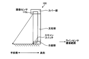
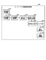
本実施形態に係るオーバーヘッド型画像読取装置100の構成の一例について図1乃至図5を参照して説明する。図1は、オーバーヘッド型画像読取装置100の概略構成の一例を示すハードウェア構成図である。図3は、オーバーヘッド型画像読取装置100を正面から見た構成の一例を示すハードウェア構成図である。図4は、オーバーヘッド型画像読取装置100の構成を側面から見た一例を示すハードウェア構成図である。図5は、オーバーヘッド型画像読取装置100の構成の一例を示す機能ブロック図である。
本実施形態に係るオーバーヘッド型画像読取装置100の構成の一例について図1乃至図5を参照して説明する。図1は、オーバーヘッド型画像読取装置100の概略構成の一例を示すハードウェア構成図である。図3は、オーバーヘッド型画像読取装置100を正面から見た構成の一例を示すハードウェア構成図である。図4は、オーバーヘッド型画像読取装置100の構成を側面から見た一例を示すハードウェア構成図である。図5は、オーバーヘッド型画像読取装置100の構成の一例を示す機能ブロック図である。
図1に示すように、オーバーヘッド型画像読取装置100は、概略的に、制御部102とメモリ等を含む記憶部106と入出力インターフェース部108とカメラ等の画像読取部110と光源120とを少なくとも備えて構成されてもよい。また、オーバーヘッド型画像読取装置100は、更に、入出力部112(図示せず)を備えていてもよい。ここで、これら各部は任意の通信路を介して通信可能に接続されている。また、オーバーヘッド型画像読取装置100は、更に、通信インターフェース部(図示せず)を備えていてもよく、通信インターフェース部を介してネットワークを経由し、外部装置(例えば、PC等)と相互に通信可能に接続されていてもよい。通信インターフェース部は、通信回線および/または電話回線等に接続されるアンテナおよび/またはルータ等の通信装置に接続されるインターフェースでありオーバーヘッド型画像読取装置100とネットワークとの間における通信制御を行う機能を有していてもよい。
ここで、記憶部106は、各種のデータベース、テーブル、および/または、ファイルなどを格納する。記憶部106は、ストレージ手段であり、例えばRAM・ROM等のメモリ、ハードディスクのような固定ディスク装置、フレキシブルディスク、および/または、光ディスク等を用いることができる。記憶部106には、CPU(Central Processing Unit)に命令を与え各種処理を行うためのコンピュータプログラム等が記録されていてもよい。ここで、記憶部106は、画像等を記憶してもよい。
また、入出力インターフェース部108は、画像読取部110および光源120等を、制御部102と接続する。ここで、入出力インターフェース部108は、入出力部112(図示せず)を、制御部102と接続してもよい。
また、画像読取部110は、上向きに設置された綴じ媒体等の原稿を、上方よりスキャンして原稿の画像を読み取る。ここで、本実施形態において、画像読取部110は、コントローラ110aと、モータ110bと、画像センサ110c(リニアセンサ(ラインセンサ))と、A/Dコンバータ110dとを備えてもよい。ここで、画像読取部110は、上向きに設置された原稿を、画像センサ110c(リニアセンサ)を用いて上方よりスキャンして原稿の画像を読み取ってもよい。コントローラ110aは、入出力インターフェース部108を介した制御部102からの指令に応じて、モータ110b、画像センサ110c(リニアセンサ)、および、A/Dコンバータ110dを制御する。画像センサ110c(リニアセンサ)は、原稿の主走査方向のラインから届く光を、ライン上の画素ごとにアナログ電荷量に光電変換する。そして、A/Dコンバータ110dは、リニアセンサから出力されたアナログ電荷量をデジタル信号に変換し、一次元の画像(ライン画像)を出力する。モータ110bが回転駆動すると、リニアセンサの読み取り対象の原稿ラインが副走査方向に移動する。これにより、ラインごとに一次元の画像がA/Dコンバータ110dから出力され、制御部102は、これらを合成することにより二次元の画像を生成する。
また、原稿を上向きに設置して、上方より画像読取部110にて原稿を撮像する場合、主走査方向のラインの一次元画像が、リニアセンサにより読み取られてもよい。そして、モータ110bの駆動によりリニアセンサが所定の回転方向に回転すると、それに伴って、リニアセンサの読み取りラインは、所定の副走査方向(例えば、奥行方向の奥側から手前側への方向等)に移動する。これにより、二次元の原稿の画像が、画像読取部110によって読み取られることとなる。
また、画像読取部110は、上向きに設置された原稿を、画像センサ110c(エリアセンサ)を用いて上方よりスキャンして原稿の画像を読み取ってもよい。ここで、本実施形態において、画像読取部110は、コントローラ110aと、画像センサ110c(エリアセンサ)と、A/Dコンバータ110dとを備えていてもよい。コントローラ110aは、入出力インターフェース部108を介した制御部102からの指令に応じて、モータ110b、画像センサ110c(エリアセンサ)、および、A/Dコンバータ110dを制御する。画像センサ110c(エリアセンサ)は、原稿平面(主走査方向と副走査方向の二次元平面)から届く光を、画素ごとにアナログ電荷量に光電変換する。そして、A/Dコンバータ110dは、エリアセンサから出力されたアナログ電荷量をデジタル信号に変換し、二次元の画像を出力する。これにより、二次元の画像がA/Dコンバータ110dから出力される。
また、入出力部112は、データの入出力(I/O)を行う。ここで、入出力部112は、例えば、キー入力部、タッチパネル、コントロールパッド(例えば、タッチパッド、および、ゲームパッド等)、マウス、キーボード、および、マイク等であってもよい。また、入出力部112は、アプリケーション等の表示画面を表示する表示部(例えば、液晶または有機EL等から構成されるディスプレイ、モニタ、および、タッチパネル等)であってもよい。また、入出力部112は、音声情報を音声として出力する音声出力部(例えば、スピーカ等)であってもよい。
また、制御部102は、オーバーヘッド型画像読取装置100を統括的に制御するCPU等からなる。制御部102は、制御プログラムと各種の処理手順等を規定したプログラムと所要データとを格納するための内部メモリを有し、これらプログラムに基づいて種々の処理を実行するための情報処理を行ってもよい。
ここで、図2を参照して、本実施形態に係る制御部102の構成の一例について説明する。図2は、本実施形態に係る制御部102の構成の一例を示す図である。
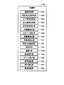
図2に示すように、制御部102は、画像取得部102a、輝度変化点検出部102b、上下輪郭生成部102c、左右輪郭生成部102d、媒体領域抽出部102e、手領域抽出部102f、交点ペア検出部102g、閉領域抽出部102h、指領域抽出部102i、色変化点抽出部102j、指判定部102k、塗潰し部102m、強調表示部102n、ポイント表示部102p、変更抽出部102q、歪み補正部102r、および、画像記録部102sを少なくとも備えて構成されてもよい。また、これら各部は任意の通信路を介して通信可能に接続されている。
画像取得部102aは、媒体を画像読取部110にて読み取らせ、読取画像を取得する。すなわち、画像取得部102aは、画像読取部110を制御して、画像を取得してもよい。例えば、画像取得部102aは、画像読取部110のコントローラ110aを制御して、モータ110bを回転駆動させ、画像センサ110c(リニアセンサ)により光電変換されA/Dコンバータ110dによりアナログデジタル変換されたラインごとの一次元画像を合成することにより、二次元の画像を取得して記憶部106に格納する処理を制御してもよい。
また、例えば、画像取得部102aは、画像読取部110のコントローラ110aを制御して、画像センサ110c(エリアセンサ)により光電変換されA/Dコンバータ110dによりアナログデジタル変換された画像を取得して記憶部106に格納する処理を制御してもよい。すなわち、画像取得部102aは、画像センサ110c(エリアセンサ)でモーション撮影を行って連続画像(動画像)を取得する機能を有していてもよい。
輝度変化点検出部102bは、読取画像の輝度変化点を検出する。ここで、輝度変化点検出部102bは、読取画像の上部と下部とから、輝度変化点を検出してもよい。
上下輪郭生成部102cは、読取画像の上部と下部とにおいて、輝度変化点の上下位置が急に変化する二点を検出し、二点間にある輝度変化点を連結して、媒体の上部輪郭および下部輪郭を生成する。
左右輪郭生成部102dは、上部輪郭および下部輪郭の端点を結ぶ二直線を媒体の左輪郭および右輪郭として生成する。
媒体領域抽出部102eは、読取画像から媒体領域を抽出する。ここで、媒体領域抽出部102eは、上部輪郭、下部輪郭、左輪郭および右輪郭に基づいて、媒体領域を抽出してもよい。
手領域抽出部102fは、読取画像に含まれる手領域を抽出する。ここで、手領域抽出部102fは、読取画像における媒体領域外の色情報を用いて、当該読取画像に含まれる手領域を抽出してもよい。また、手領域抽出部102fは、読取画像における媒体領域外の色情報を用いた2値画像を生成することにより、読取画像に含まれる手領域を抽出してもよい。
交点ペア検出部102gは、媒体領域の輪郭である媒体輪郭と、手領域の輪郭である手輪郭と、の交点ペアを検出する。
閉領域抽出部102hは、交点ペアを含む閉領域を抽出する。
指領域抽出部102iは、媒体領域内の指領域を抽出する。ここで、指領域抽出部102iは、閉領域の位置に基づいて、媒体領域内の指領域を抽出してもよい。ここで、指領域抽出部102iは、閉領域が媒体領域内にある場合、当該閉領域を指領域として抽出してもよい。また、指領域抽出部102iは、指の肌と爪との色変化点の前後の二つの色情報を用いて、媒体領域内の指領域を抽出してもよい。ここで、指領域抽出部102iは、色変化点の前後の二つの色情報を用いた2値画像を生成することにより、読取画像に含まれる媒体領域内の指領域を抽出してもよい。
色変化点抽出部102jは、交点ペアの各交点を通る、手輪郭に基づく指方向の方向線を検出し、二つの方向線の中間線上の指の肌と爪との色変化点を抽出する。ここで、方向線は、交点ペアの各交点の接線であってもよく、交点ペアの各交点を通る手輪郭の近似直線であってもよく、交点ペアの各交点を通らない手輪郭の近似直線であってもよい。
指判定部102kは、交点ペア間の距離、指領域の重心、および/または、指領域の幅に基づいて、指領域が指だと確信できるものであるか否か判定する。
塗潰し部102mは、指領域内の読取画像を、媒体領域内、且つ、指領域周囲の読取画像の色情報を用いて塗り潰す。
強調表示部102nは、指判定部102kにより指領域が指だと確信できるものでないと判定された場合、交点ペア間を強調して読取画像を表示させる。ここで、強調表示部102nは、指判定部102kにより指領域が指だと確信できるものでないと判定された場合、交点ペア間を点滅させて読取画像を表示させてもよい。また、強調表示部102nは、指判定部102kにより指領域が指だと確信できるものでないと判定された場合、交点ペア間を強調して読取画像を入出力部112に表示させてもよい。また、強調表示部102nは、指領域の周囲を強調して表示させてもよい。
ポイント表示部102pは、指判定部102kにより指領域が指だと確信できるものでないと判定された場合、交点ペア以外の指だと確信できない指領域の周囲に変更可能なポイントを追加して読取画像を表示させる。ここで、ポイント表示部102pは、指判定部102kにより指領域が指だと確信できるものでないと判定された場合、交点ペア以外の指だと確信できない指領域の周囲に変更可能なポイントを追加して読取画像を入出力部112に表示させてもよい。
変更抽出部102qは、ユーザによりポイントの位置が変更された場合、当該変更後の指だと確信できない指領域を指領域として抽出する。ここで、変更抽出部102qは、ユーザにより入出力部112を介してポイントの位置が変更された場合、当該変更後の指だと確信できない指領域を指領域として抽出してもよい。
歪み補正部102rは、画像の歪みを補正し、補正画像を取得する。ここで、歪み補正部102rは、画像を、射影変換(例えば、正面方向から撮影したように射影変換)することで、画像の歪みを補正してもよい。また、補正画像は、最終結果画像であってもよい。また、補正は、幾何補正であってもよい。
画像記録部102sは、画像を記憶部106に格納する。ここで、画像記録部102sは、補正画像を記憶部106に格納してもよい。また、画像記録部102sは、画像読取部110にて読み取られた画像等を記憶部106に格納してもよい。また、画像記録部102sは、画像取得部102aにより取得された画像等を記憶部106に格納してもよい。ここで、画像記録部102sは、媒体領域の画像を記憶部106に格納してもよい。また、画像記録部102sは、手領域の画像を記憶部106に格納してもよい。
なお、制御部102は、画像を入出力部112を介して出力させてもよい。ここで、制御部102は、画像(例えば、補正前画像、補正後画像、または、最終結果画像等)を入出力部112に表示させてもよい。また、制御部102は、画像読取部110にて読み取られた読取画像等を入出力部112に表示させてもよい。
また、図3および図4に示すように、オーバーヘッド型画像読取装置100は、台座部、支柱部およびカバー部を有する。ここで、図3および図4に示すように、台座部は、画像読取開始を指示するスキャンスイッチを備えていてもよい。また、図3および図4に示すように、カバー部は、ラインセンサ等を含む画像センサ110cを備えており、台座部前方のラインセンサ撮像範囲に載置された媒体を読み取ってもよい。
なお、本実施形態におけるオーバーヘッド型画像読取装置100は、更に、綴じ媒体の積載台を備えていてもよい。また、画像読取部110は、積載台の上部に配置され、積載台を撮像してもよい。また、制御部102は、画像読取部110を制御してもよい。
また、図5に示すように、本実施形態におけるオーバーヘッド型画像読取装置100において、媒体画像取得部(画像取得部)102aが、媒体を画像読取部110にて読み取らせ、読取画像を取得し、媒体輪郭抽出部(媒体領域抽出部)102eが、読取画像から媒体輪郭を抽出し、手指輪郭抽出部(手領域抽出部)102fが、読取画像における媒体領域外の色情報を用いて、当該読取画像に含まれる手輪郭を抽出し、交点ペア検出部102gが、媒体輪郭と手輪郭との交点ペアを検出し、交点ペア間輪郭判定部(指判定部)102kが、交点ペア間の距離、指領域の重心、および/または、指領域の幅に基づいて、交点ペア間輪郭の指近似性を判定し、指塗潰し部(塗潰し部)102mが、指近似性があると判定された交点ペア間輪郭(指領域)内の読取画像を、媒体領域内、且つ、指領域周囲の読取画像の色情報を用いて塗り潰し、リカバリ部(変更抽出部)102qが、指近似性がないと判定された交点ペア間輪郭(指領域)をユーザに変更させ、リカバリ部(塗潰し部)102mが、指領域内の読取画像を塗り潰し、歪み補正部102rが、読取画像の歪みを補正し、補正画像を取得し、画像記録部102sが、補正画像を記憶部106に格納してもよい。
[2.本実施形態の処理]
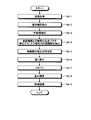
上述した構成のオーバーヘッド型画像読取装置100で実行される処理の一例について、図6乃至図27を参照して説明する。図6は、本実施形態のオーバーヘッド型画像読取装置100における処理の一例を示すフローチャートである。
上述した構成のオーバーヘッド型画像読取装置100で実行される処理の一例について、図6乃至図27を参照して説明する。図6は、本実施形態のオーバーヘッド型画像読取装置100における処理の一例を示すフローチャートである。
図6に示すように、まず、画像取得部102aは、ユーザによりめくられた媒体を画像読取部110にて読み取らせ、読取画像を取得する(ステップSA-1)。
そして、媒体領域抽出部102eは、読取画像から媒体輪郭(媒体領域の外縁)を抽出する(ステップSA-2)。ここで、媒体領域抽出部102eは、上部輪郭、下部輪郭、左輪郭および右輪郭に基づいて、媒体輪郭(媒体領域の外縁)を抽出してもよい。
ここで、図7乃至図10を参照して、本実施形態における媒体輪郭抽出処理の一例について説明する。図7は、本実施形態における媒体輪郭抽出処理の一例を示すフローチャートである。図8は、本実施形態における変化点検出の一例を示す図である。図9は、本実施形態における上部輪郭/下部輪郭生成の一例を示す図である。図10は、本実施形態における左輪郭/右輪郭生成の一例を示す図である。
図7に示すように、まず、輝度変化点検出部102bは、画像取得部102aにより取得された媒体画像(読取画像)を取得する(ステップSB-1)。
そして、輝度変化点検出部102bは、媒体画像の上部と下部とから、輝度の変化点(輝度変化点)を検出する(ステップSB-2)。
例えば、図8に示すように、輝度変化点検出部102bは、媒体画像の下部から走査することで輝度の変化点を複数検出してもよい。
図7に戻り、上下輪郭生成部102cは、媒体画像の上下別に、媒体画像の真ん中の輝度変化点から両端に走査する(ステップSB-3)。
そして、上下輪郭生成部102cは、媒体画像の上部と下部とにおいて、輝度変化点の高さ(すなわち、上下(垂直)方向の座標値)が急に変化するところ(すなわち、輝度変化点の上下位置が急に変化する二点)を検出する(ステップSB-4)。
そして、上下輪郭生成部102cは、媒体画像の上下別に残った輝度変化点を連結して、媒体の上部輪郭と下部輪郭とを生成する(ステップSB-5)。
例えば、図9に示すように、上下輪郭生成部102cは、媒体画像の上部と下部とそれぞれに、輝度変化点の上下位置が急に変化する二点間にある輝度変化点を連結して、媒体の上部輪郭および下部輪郭を生成してもよい。
図7に戻り、左右輪郭生成部102dは、上部輪郭と下部輪郭との左右それぞれの端点を連結して、左輪郭と右輪郭とを生成し(ステップSB-6)、処理を終了する。
例えば、図10に示すように、左右輪郭生成部102dは、上部輪郭および下部輪郭の端点を結ぶ二直線を媒体の左輪郭および右輪郭として生成してもよい。
図6に戻り、手領域抽出部102fは、読取画像に含まれる手輪郭(手領域の外縁)を抽出する(ステップSA-3)。
ここで、図11乃至図14を参照して、本実施形態における手輪郭抽出処理の一例について説明する。図11は、本実施形態における手輪郭抽出処理の一例を示すフローチャートである。図12は、本実施形態における前景抽出の一例を示す図である。図13は、本実施形態における2値画像生成の一例を示す図である。図14は、本実施形態における手輪郭抽出の一例を示す図である。
図11に示すように、まず、手領域抽出部102fは、媒体の左輪郭の左側と、媒体の右輪郭の右側とから、読取画像の前景を抽出する(ステップSC-1)。
例えば、図12に示すように、手領域抽出部102fは、媒体の左輪郭の左側と、媒体の右輪郭の右側とから、読取画像の前景、すなわち、読取画像に含まれる媒体領域の外側の手領域を抽出してもよい。
図11に戻り、手領域抽出部102fは、前景画像から色モデルを生成する(ステップSC-2)。
そして、手領域抽出部102fは、色モデルにて全画像からモデルに当て嵌まるピクセルを検出して、2値画像を生成する(ステップSC-3)。
例えば、図13に示すように、手領域抽出部102fは、読取画像における媒体領域外の手領域から生成した色モデルを用いて、読取画像からモデルに当て嵌まるピクセルを検出して、読取画像全体に含まれる手の2値画像である手領域を生成してもよい。
図11に戻り、手領域抽出部102fは、2値画像から手輪郭を抽出し(ステップSC-4)、処理を終了する。すなわち、本実施形態においては、撮像範囲以内、媒体外側の色情報を使って指検出を行ってもよい。
例えば、図14に示すように、手領域抽出部102fは、2値画像である手領域の外縁を、読取画像に含まれる手輪郭として抽出してもよい。
図6に戻り、交点ペア検出部102gは、媒体輪郭と手輪郭との交点ペアを検出し、指領域抽出部102iは、媒体領域内(媒体輪郭内部)の指輪郭を抽出する(ステップSA-4)。
ここで、図15乃至図19を参照して、本実施形態における指領域抽出処理の一例について説明する。
[指領域抽出処理(1)]
まず、図15および図16を参照して、本実施形態における指領域抽出処理の一例について説明する。図15は、本実施形態における指領域抽出処理の一例を示すフローチャートである。図16は、本実施形態における指領域抽出の一例を示す図である。
まず、図15および図16を参照して、本実施形態における指領域抽出処理の一例について説明する。図15は、本実施形態における指領域抽出処理の一例を示すフローチャートである。図16は、本実施形態における指領域抽出の一例を示す図である。
図15に示すように、まず、交点ペア検出部102gは、各輪郭のサブ線分を走査して媒体の左(右)輪郭との交点を検出する(ステップSD-1)。
そして、閉領域抽出部102hは、交点ペアを含む閉領域を抽出し、媒体の左(右)輪郭の上から順に交点ペアの間の輪郭、すなわち、交点ペアを含む閉領域の輪郭をチェックする(ステップSD-2)。
そして、閉領域抽出部102hは、交点ペアを含む閉領域が、媒体の左(右)輪郭の右側(左側)にあるか否か、すなわち、媒体領域内にあるか否か判定する(ステップSD-3)。
そして、閉領域抽出部102hは、交点ペアを含む閉領域が、媒体の左(右)輪郭の右側(左側)にないと判定した場合(ステップSD-3:No)、処理をステップSD-2に移行させる。
一方、指領域抽出部102iは、閉領域抽出部102hにより交点ペアを含む閉領域が、媒体の左(右)輪郭の右側(左側)にあると判定された場合(ステップSD-3:Yes)、交点ペアを含む閉領域を指領域として抽出し、当該交点ペアを指領域に含まれるものとして記憶部106に記録する(ステップSD-4)。そして、指領域抽出部102iは、交点ペアが残っている場合、処理をステップSD-2に移行させ、交点ペアが残っていない場合、処理を終了する。すなわち、本実施形態においては、媒体輪郭と手輪郭との交点を検出して媒体内側にある指領域を検出してもよい。
例えば、図16に示すように、指領域抽出部102iは、交点ペア1(交点aおよび交点b)を含む閉領域5が媒体領域の内側にあるので、交点ペア1を含む閉領域5を指領域として抽出してもよい。また、図16に示すように、指領域抽出部102iは、交点ペア2(交点bおよび交点c)を含む閉領域6が媒体領域の外側にあるので、交点ペア2を含む閉領域6を指領域として抽出しなくてもよい。また、図16に示すように、指領域抽出部102iは、交点ペア3(交点cおよび交点d)を含む閉領域7が媒体領域の内側にあるので、交点ペア3を含む閉領域7を指領域として抽出してもよい。また、図16に示すように、指領域抽出部102iは、交点ペア4(交点eおよび交点f)を含む閉領域8が媒体領域の内側にあるので、交点ペア4を含む閉領域8を指領域として抽出してもよい。
[指領域抽出処理(2)]
また、図17乃至図19を参照して、本実施形態における指領域抽出処理の一例について説明する。図17は、本実施形態における指領域抽出処理の一例を示すフローチャートである。図18は、本実施形態における色変化点抽出の一例を示す図である。図19は、本実施形態における色モデル構築の一例を示す図である。
また、図17乃至図19を参照して、本実施形態における指領域抽出処理の一例について説明する。図17は、本実施形態における指領域抽出処理の一例を示すフローチャートである。図18は、本実施形態における色変化点抽出の一例を示す図である。図19は、本実施形態における色モデル構築の一例を示す図である。
図17に示すように、まず、交点ペア検出部102gは、各輪郭のサブ線分を走査して媒体の左(右)輪郭との交点を検出する(ステップSE-1)。
そして、色変化点抽出部102jは、交点ペアの交点外の指方向を用いて方向線を検出して、すなわち、交点ペアの各交点を通る、手輪郭に基づく指方向の方向線を検出して、指の中間線、すなわち、二つの方向線の中間線を決める(ステップSE-2)。ここで、方向線は、交点ペアの各交点の接線であってもよく、交点ペアの各交点を通る手輪郭の近似直線であってもよい。
そして、色変化点抽出部102jは、中間線を走査してエッジ強度で指の肌と甲(爪)との変化点(色変化点)を見つける(ステップSE-3)。
例えば、図18に示すように、色変化点抽出部102jは、二つの方向線の中間線を走査してエッジ強度で、中間線上の指の肌と爪との色変化点を抽出してもよい。
図17に戻り、指領域抽出部102iは、指の肌と甲(爪)との色変化点の前後を中心として別々の色モデルを構築する(ステップSE-4)。
例えば、図19に示すように、指領域抽出部102iは、指の肌と爪との色変化点の前後の二つの色モデルを構築してもよい。
図17に戻り、指領域抽出部102iは、二つの色モデルで媒体領域内の指輪郭を検出(抽出)し、指領域に含まれる交点ペアを記憶部106に記録し(ステップSE-5)、処理を終了する。ここで、指領域抽出部102iは、二つの色モデルを用いた2値画像を生成することにより、読取画像に含まれる指領域を抽出してもよい。
図6に戻り、指判定部102kは、指輪郭の指近似性を判定する(ステップSA-5)。
ここで、図20乃至図23を参照して、本実施形態における交点ペアチェック処理の一例について説明する。図20は、本実施形態における媒体輪郭抽出処理の一例を示すフローチャートである。図21は、本実施形態における重心解析の一例を示す図である。図22は、本実施形態における幅解析の一例を示す図である。図23は、本実施形態における幅解析の一例を示す図である。
図20に示すように、まず、指判定部102kは、記憶部106に記憶された交点ペアを含む指領域を取得する(ステップSF-1)。
そして、指判定部102kは、交点ペアの間の輪郭(直線)の長さを計算する(ステップSF-2)。
そして、指判定部102kは、計算した輪郭の長さが閾値以下であるか否か判定する(ステップSF-3)。
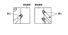
そして、指判定部102kは、輪郭の長さが閾値以下でない(より大きい)と判定した場合(ステップSF-3:No)、処理をステップSF-8に移行させ、指だと確信できない指領域に含まれる交点ペアとして記憶部106に記録する(ステップSF-8)。すなわち、指判定部102kは、指領域が指の幅より明らかに広い場合、指領域が指だと確信できるものでないと判定してもよい。
一方、指判定部102kは、輪郭の長さが閾値以下であると判定した場合(ステップSF-3:Yes)、媒体領域内の指輪郭の重心を計算し、重心の媒体左(右)輪郭からの距離を計算する(ステップSF-4)。
例えば、図21左図に示すように、指判定部102kは、指領域の重心を計算し、媒体左輪郭から当該重心までの距離(最小距離)を計算してもよい。また、図21右図に示すように、指判定部102kは、二箇所の指領域の重心をそれぞれ計算し、媒体右輪郭から当該重心までの距離(最小距離)をそれぞれ計算してもよい。
図20に戻り、指判定部102kは、計算した指輪郭の重心の媒体左(右)輪郭からの距離が閾値以下であるか否か判定する(ステップSF-5)。
そして、指判定部102kは、指輪郭の重心の媒体左(右)輪郭からの距離が閾値以下でない(より大きい)と判定した場合(ステップSF-5:No)、処理をステップSF-8に移行させ、指だと確信できない指領域に含まれる交点ペアとして記憶部106に記録する(ステップSF-8)。すなわち、指判定部102kは、指領域の重心が媒体輪郭から明らかに遠い場合、指領域が指だと確信できるものでないと判定してもよい。
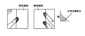
一方、指判定部102kは、指輪郭の重心の媒体左(右)輪郭からの距離が閾値以下であると判定した場合(ステップSF-5:Yes)、交点ペアを連結する直線(交点ペア間)の方向に平行する指輪郭の複数の幅を計算して、指輪郭の各幅が交点ペアを連結する直線の長さを越える割合を統計解析する(ステップSF-6)。すなわち、指判定部102kは、指輪郭の幅変化を集計し、統計解析してもよい。
そして、指判定部102kは、指輪郭の各幅が交点ペアを連結する直線の長さを越える割合が閾値以下であるか否か判定する(ステップSF-7)。
そして、指判定部102kは、指輪郭の各幅が交点ペアを連結する直線の長さを越える割合が閾値以下でない(より大きい)と判定した場合(ステップSF-7:No)、処理をステップSF-8に移行させ、指だと確信できない指領域に含まれる交点ペアとして記憶部106に記録する(ステップSF-8)。すなわち、指判定部102kは、指領域の形状が指の形状(例えば、根元から先に向かって幅が狭くなる形状等)と明らかに異なる場合、指領域が指だと確信できるものでないと判定してもよい。
例えば、図22に示すように、指判定部102kは、交点ペアを連結する直線(交点ペア間)の方向に平行する指輪郭の複数の幅を計算して、指輪郭の幅変化を集計し、統計解析することにより、指輪郭がノイズのある時の幅変化であると判定してもよい。すなわち、図22は、媒体の色が指の肌の色に近く、指輪郭が正常に抽出されない場合の幅解析の一例を示している。
図20に戻り、指判定部102kは、指輪郭の各幅が交点ペアを連結する直線の長さを越える割合が閾値以下であると判定した場合(ステップSF-7:Yes)、指だと確信できる指領域に含まれる交点ペアとして記憶部106に記録する(ステップSF-8)。
例えば、図23に示すように、指判定部102kは、交点ペアを連結する直線(交点ペア間)の方向に平行する指輪郭の複数の幅を計算して、指輪郭の幅変化を集計し、統計解析することにより、指輪郭が正常な指の幅変化であると判定してもよい。
図20に戻り、指判定部102kは、指領域抽出部102iにより抽出された媒体領域内の指領域に含まれる全ての交点ペアをチェックしたか判定する(ステップSF-9)。
そして、指判定部102kは、指領域抽出部102iにより抽出された媒体領域内の指領域に含まれる全ての交点ペアをチェックしていないと判定した場合(ステップSF-9:No)、処理をステップSF-1に移行させる。
一方、指判定部102kは、指領域抽出部102iにより抽出された媒体領域内の指領域に含まれる全ての交点ペアをチェックしたと判定した場合(ステップSF-9:Yes)、処理を終了する。すなわち、本実施形態においては、指近似性を計算、判断してもよい。
図6に戻り、塗潰し部102mは、指判定部102kにより指輪郭の指近似性があると判定された場合(ステップSA-5)、指領域内の読取画像を、媒体領域内、且つ、指領域周囲の読取画像の色情報を用いて塗り潰す(ステップSA-6)。
そして、変更抽出部102qは、指判定部102kにより指輪郭の指近似性がないと判定された場合(ステップSA-5)、ユーザに指輪郭を変更させ、塗潰し部102mは、輪郭変更後の指領域内の読取画像を、媒体領域内、且つ、指領域周囲の読取画像の色情報を用いて塗り潰すことでリカバリを行う(ステップSA-7)。なお、本実施形態において、指領域抽出処理において指領域抽出処理(1)を行った場合、リカバリ処理において指領域抽出処理(2)を含む処理を行ってもよく、指領域抽出処理において指領域抽出処理(2)を行った場合、リカバリ処理において指領域抽出処理(1)を含む処理を行ってもよい。
ここで、図24乃至図26を参照して、本実施形態におけるリカバリ処理の一例について説明する。図24は、本実施形態におけるリカバリ処理の一例を示すフローチャートである。図25は、本実施形態における強調表示の一例を示す図である。図26は、本実施形態におけるポイント表示の一例を示す図である。
図24に示すように、まず、強調表示部102nは、記憶部106に記憶された指だと確信できない交点ペアを含む指領域を取得する(ステップSG-1)。
そして、強調表示部102nは、読取画像上に、交点ペアを連結する直線を直径とする円を点滅させて入出力部112に表示させる(ステップSG-2)。
例えば、図25に示すように、強調表示部102nは、交点ペア間を点滅させて読取画像を表示させてもよい。
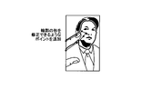
図24に戻り、ポイント表示部102pは、交点ペア以外の指だと確信できない指領域の周囲に、指輪郭の形を修正できるような(変更可能な)ポイントを追加して読取画像を入出力部112に表示させる(ステップSG-3)。
例えば、図26に示すように、ポイント表示部102pは、輪郭の形を修正できるようなポイントを追加して読取画像を表示させてもよい。
図24に戻り、強調表示部102nは、指領域、および/または、読取画像の全体の周囲を点滅させて入出力部112に表示させる(ステップSG-4)。
そして、塗潰し部102mは、ユーザにより入出力部112を介して表示されたポイントが動かされることで指輪郭の形が修正された場合、ユーザ修正後の指輪郭で、指領域内の読取画像を、媒体領域内、且つ、指領域周囲の読取画像の色情報を用いて塗り潰し(ステップSG-5)、処理を終了する。すなわち、本実施形態において、UIによるエラー部分の通知を行い、ユーザによるマニュアル補正を行わせることによりリカバリしてもよい。
図6に戻り、歪み補正部102rは、読取画像の歪みを補正し、補正画像を最終結果画像として取得する(ステップSA-8)。このように、本実施形態においては、媒体輪郭と押さえ手の手輪郭との交点を検出して、交点間の媒体輪郭内側に存在する部分輪郭特徴を調べ、指だと確信できれば、周囲の情報で塗り潰して指領域を消し、確信できなければ、リカバリしてもよい。
ここで、図27を参照して、本実施形態における最終結果画像の一例について説明する。図27は、本実施形態における最終結果画像の一例を示す図である。
図27に示すように、本実施形態における最終結果画像においては、読取画像をクロッピングすることにより媒体領域を抽出し、媒体領域に映り込んだ手指を示す指領域を塗り潰し、歪み補正を行ったものであってもよい。
図6に戻り、画像記録部102sは、最終結果画像を記憶部106に記録(格納)し(ステップSA-9)、処理を終了する。
[3.他の実施形態]
さて、これまで本発明の実施形態について説明したが、本発明は、上述した実施形態以外にも、特許請求の範囲に記載した技術的思想の範囲内において種々の異なる実施形態にて実施されてよいものである。
さて、これまで本発明の実施形態について説明したが、本発明は、上述した実施形態以外にも、特許請求の範囲に記載した技術的思想の範囲内において種々の異なる実施形態にて実施されてよいものである。
例えば、オーバーヘッド型画像読取装置100は、スタンドアローンの形態で処理を行ってもよく、クライアント端末(オーバーヘッド型画像読取装置100とは別筐体である)からの要求に応じて処理を行い、その処理結果を当該クライアント端末に返却するようにしてもよい。
また、実施形態において説明した各処理のうち、自動的に行われるものとして説明した処理の全部または一部を手動的に行うこともでき、あるいは、手動的に行われるものとして説明した処理の全部または一部を公知の方法で自動的に行うこともできる。
このほか、明細書中および図面中で示した処理手順、制御手順、具体的名称、各処理の登録データもしくは検索条件等のパラメータを含む情報、画面例、または、データベース構成については、特記する場合を除いて任意に変更することができる。
また、オーバーヘッド型画像読取装置100に関して、図示の各構成要素は機能概念的なものであり、必ずしも物理的に図示の如く構成されていることを要しない。
例えば、オーバーヘッド型画像読取装置100の各装置が備える処理機能、特に制御部102にて行われる各処理機能については、その全部または任意の一部を、CPU(Central Processing Unit)および当該CPUにて解釈実行されるプログラムにて実現してもよく、また、ワイヤードロジックによるハードウェアとして実現してもよい。尚、プログラムは、後述する、コンピュータに本発明に係る方法を実行させるためのプログラム化された命令を含む、一時的でないコンピュータ読み取り可能な記録媒体に記録されており、必要に応じてオーバーヘッド型画像読取装置100に機械的に読み取られる。すなわち、ROMまたはHDD(Hard Disk Drive)などの記憶部106などには、OS(Operating System)と協働してCPUに命令を与え、各種処理を行うためのコンピュータプログラムが記録されている。このコンピュータプログラムは、RAMにロードされることによって実行され、CPUと協働して制御部を構成する。
また、このコンピュータプログラムは、オーバーヘッド型画像読取装置100に対して任意のネットワークを介して接続されたアプリケーションプログラムサーバに記憶されていてもよく、必要に応じてその全部または一部をダウンロードすることも可能である。
また、本発明に係るプログラムを、コンピュータ読み取り可能な記録媒体に格納してもよく、また、プログラム製品として構成することもできる。ここで、この「記録媒体」とは、メモリーカード、USBメモリ、SDカード、フレキシブルディスク、光磁気ディスク、ROM、EPROM、EEPROM、CD-ROM、MO、DVD、および、Blu-ray(登録商標) Disc等の任意の「可搬用の物理媒体」を含むものとする。
また、「プログラム」とは、任意の言語や記述方法にて記述されたデータ処理方法であり、ソースコードやバイナリコード等の形式を問わない。なお、「プログラム」は必ずしも単一的に構成されるものに限られず、複数のモジュールやライブラリとして分散構成されるものや、OS(Operating System)に代表される別個のプログラムと協働してその機能を達成するものをも含む。なお、実施形態に示した各装置において記録媒体を読み取るための具体的な構成、読み取り手順、あるいは、読み取り後のインストール手順等については、周知の構成や手順を用いることができる。
記憶部106に格納される各種のデータベース等は、RAMもしくはROM等のメモリ装置、ハードディスク等の固定ディスク装置、フレキシブルディスク、および/または、光ディスク等のストレージ手段であり、各種処理やウェブサイト提供に用いる各種のプログラム、テーブル、データベース、および/または、ウェブページ用ファイル等を格納してもよい。
また、オーバーヘッド型画像読取装置100は、既知のパーソナルコンピュータ、ワークステーション等の情報処理装置として構成してもよく、また、該情報処理装置に任意の周辺装置を接続して構成してもよい。また、オーバーヘッド型画像読取装置100は、該情報処理装置に本発明の方法を実現させるソフトウェア(プログラム、データ等を含む)を実装することにより実現してもよい。
更に、装置の分散・統合の具体的形態は図示するものに限られず、その全部または一部を、各種の付加等に応じて、または、機能負荷に応じて、任意の単位で機能的または物理的に分散・統合して構成することができる。すなわち、上述した実施形態を任意に組み合わせて実施してもよく、実施形態を選択的に実施してもよい。
以上のように、本発明に係るオーバーヘッド型画像読取装置、画像処理方法、および、プログラムは、産業上の多くの分野、特にスキャナで読み取った画像を扱う画像処理分野で実施することができ、極めて有用である。
100 オーバーヘッド型画像読取装置(オーバーヘッドスキャナ装置)
102 制御部
102a 画像取得部
102b 輝度変化点検出部
102c 上下輪郭生成部
102d 左右輪郭生成部
102e 媒体領域抽出部
102f 手領域抽出部
102g 交点ペア検出部
102h 閉領域抽出部
102i 指領域抽出部
102j 色変化点抽出部
102k 指判定部
102m 塗潰し部
102n 強調表示部
102p ポイント表示部
102q 変更抽出部
102r 歪み補正部
102s 画像記録部
106 記憶部
108 入出力インターフェース部
110 画像読取部
110a コントローラ
110b モータ
110c 画像センサ
110d A/Dコンバータ
112 入出力部
120 光源
102 制御部
102a 画像取得部
102b 輝度変化点検出部
102c 上下輪郭生成部
102d 左右輪郭生成部
102e 媒体領域抽出部
102f 手領域抽出部
102g 交点ペア検出部
102h 閉領域抽出部
102i 指領域抽出部
102j 色変化点抽出部
102k 指判定部
102m 塗潰し部
102n 強調表示部
102p ポイント表示部
102q 変更抽出部
102r 歪み補正部
102s 画像記録部
106 記憶部
108 入出力インターフェース部
110 画像読取部
110a コントローラ
110b モータ
110c 画像センサ
110d A/Dコンバータ
112 入出力部
120 光源
Claims (19)
- 媒体を画像読取部にて読み取らせ、読取画像を取得する画像取得手段と、
前記読取画像における媒体領域外の色情報を用いて、当該読取画像に含まれる手領域を抽出する手領域抽出手段と、
を備えたことを特徴とする、オーバーヘッド型画像読取装置。 - 前記媒体領域の輪郭である媒体輪郭と、前記手領域の輪郭である手輪郭と、の交点ペアを検出する交点ペア検出手段と、
前記交点ペアを含む閉領域を抽出する閉領域抽出手段と、
前記閉領域の位置に基づいて、前記媒体領域内の指領域を抽出する指領域抽出手段と、
を更に備えた、請求項1に記載のオーバーヘッド型画像読取装置。 - 前記交点ペア間の距離、前記指領域の重心、および/または、前記指領域の幅に基づいて、前記指領域が指だと確信できるものであるか否か判定する指判定手段、
を更に備えた、請求項2に記載のオーバーヘッド型画像読取装置。 - 前記媒体領域の輪郭である媒体輪郭と、前記手領域の輪郭である手輪郭と、の交点ペアを検出する交点ペア検出手段と、
前記交点ペアの各交点を通る、前記手輪郭に基づく指方向の方向線を検出し、二つの前記方向線の中間線上の指の肌と爪との色変化点を抽出する色変化点抽出手段と、
前記色変化点の前後の二つの色情報を用いて、前記媒体領域内の指領域を抽出する指領域抽出手段と、
を更に備えた、請求項1に記載のオーバーヘッド型画像読取装置。 - 前記指判定手段により前記指領域が前記指だと確信できるものでないと判定された場合、前記交点ペア間を強調して前記読取画像を表示させる強調表示手段、
を更に備えた、請求項3に記載のオーバーヘッド型画像読取装置。 - 前記指判定手段により前記指領域が前記指だと確信できるものでないと判定された場合、前記交点ペア以外の指だと確信できない前記指領域の周囲に変更可能なポイントを追加して前記読取画像を表示させるポイント表示手段と、
ユーザにより前記ポイントの位置が変更された場合、当該変更後の前記指だと確信できない指領域を前記指領域として抽出する変更抽出手段と、
を更に備えた、請求項3に記載のオーバーヘッド型画像読取装置。 - 前記指領域抽出手段は、
前記閉領域が前記媒体領域内にある場合、当該閉領域を前記指領域として抽出する、請求項2または3に記載のオーバーヘッド型画像読取装置。 - 前記読取画像の上部と下部とから、輝度変化点を検出する輝度変化点検出手段と、
前記読取画像の上部と下部とにおいて、前記輝度変化点の上下位置が急に変化する二点を検出し、前記二点間にある前記輝度変化点を連結して、前記媒体の上部輪郭および下部輪郭を生成する上下輪郭生成手段と、
前記上部輪郭および前記下部輪郭の端点を結ぶ二直線を前記媒体の左輪郭および右輪郭として生成する左右輪郭生成手段と、
前記上部輪郭、前記下部輪郭、前記左輪郭および前記右輪郭に基づいて、前記媒体領域を抽出する媒体領域抽出手段と、
を更に備えた、請求項1乃至7のいずれか一つに記載のオーバーヘッド型画像読取装置。 - 前記指領域内の前記読取画像を、前記媒体領域内、且つ、前記指領域周囲の前記読取画像の色情報を用いて塗り潰す塗潰し手段、
を更に備えた、請求項2乃至7のいずれか一つに記載のオーバーヘッド型画像読取装置。 - オーバーヘッド型画像読取装置で実行される、
媒体を画像読取部にて読み取らせ、読取画像を取得する画像取得ステップと、
前記読取画像における媒体領域外の色情報を用いて、当該読取画像に含まれる手領域を抽出する手領域抽出ステップと、
を含むことを特徴とする画像処理方法。 - 前記媒体領域の輪郭である媒体輪郭と、前記手領域の輪郭である手輪郭と、の交点ペアを検出する交点ペア検出ステップと、
前記交点ペアを含む閉領域を抽出する閉領域抽出ステップと、
前記閉領域の位置に基づいて、前記媒体領域内の指領域を抽出する指領域抽出ステップと、
を更に含む、請求項10に記載の画像処理方法。 - 前記交点ペア間の距離、前記指領域の重心、および/または、前記指領域の幅に基づいて、前記指領域が指だと確信できるものであるか否か判定する指判定ステップ、
を更に含む、請求項11に記載の画像処理方法。 - 前記媒体領域の輪郭である媒体輪郭と、前記手領域の輪郭である手輪郭と、の交点ペアを検出する交点ペア検出ステップと、
前記交点ペアの各交点を通る、前記手輪郭に基づく指方向の方向線を検出し、二つの前記方向線の中間線上の指の肌と爪との色変化点を抽出する色変化点抽出ステップと、
前記色変化点の前後の二つの色情報を用いて、前記媒体領域内の指領域を抽出する指領域抽出ステップと、
を更に含む、請求項10に記載の画像処理方法。 - 前記指判定ステップにて前記指領域が前記指だと確信できるものでないと判定された場合、前記交点ペア間を強調して前記読取画像を表示させる強調表示ステップ、
を更に含む、請求項12に記載の画像処理方法。 - 前記指判定ステップにて前記指領域が前記指だと確信できるものでないと判定された場合、前記交点ペア以外の指だと確信できない前記指領域の周囲に変更可能なポイントを追加して前記読取画像を表示させるポイント表示ステップと、
ユーザにより前記ポイントの位置が変更された場合、当該変更後の前記指だと確信できない指領域を前記指領域として抽出する変更抽出ステップと、
を更に含む、請求項12に記載の画像処理方法。 - 前記指領域抽出ステップは、
前記閉領域が前記媒体領域内にある場合、当該閉領域を前記指領域として抽出する、請求項11または12に記載の画像処理方法。 - 前記読取画像の上部と下部とから、輝度変化点を検出する輝度変化点検出ステップと、
前記読取画像の上部と下部とにおいて、前記輝度変化点の上下位置が急に変化する二点を検出し、前記二点間にある前記輝度変化点を連結して、前記媒体の上部輪郭および下部輪郭を生成する上下輪郭生成ステップと、
前記上部輪郭および前記下部輪郭の端点を結ぶ二直線を前記媒体の左輪郭および右輪郭として生成する左右輪郭生成ステップと、
前記上部輪郭、前記下部輪郭、前記左輪郭および前記右輪郭に基づいて、前記媒体領域を抽出する媒体領域抽出ステップと、
を更に含む、請求項10乃至16のいずれか一つに記載の画像処理方法。 - 前記指領域内の前記読取画像を、前記媒体領域内、且つ、前記指領域周囲の前記読取画像の色情報を用いて塗り潰す塗潰しステップ、
を更に含む、請求項11乃至16のいずれか一つに記載の画像処理方法。 - オーバーヘッド型画像読取装置に実行させるための、
媒体を画像読取部にて読み取らせ、読取画像を取得する画像取得ステップと、
前記読取画像における媒体領域外の色情報を用いて、当該読取画像に含まれる手領域を抽出する手領域抽出ステップと、
を含むことを特徴とするプログラム。
Priority Applications (2)
| Application Number | Priority Date | Filing Date | Title |
|---|---|---|---|
| PCT/JP2014/053501 WO2015121980A1 (ja) | 2014-02-14 | 2014-02-14 | オーバーヘッド型画像読取装置、画像処理方法、および、プログラム |
| JP2015562650A JP6181778B2 (ja) | 2014-02-14 | 2014-02-14 | オーバーヘッド型画像読取装置、画像処理方法、および、プログラム |
Applications Claiming Priority (1)
| Application Number | Priority Date | Filing Date | Title |
|---|---|---|---|
| PCT/JP2014/053501 WO2015121980A1 (ja) | 2014-02-14 | 2014-02-14 | オーバーヘッド型画像読取装置、画像処理方法、および、プログラム |
Publications (1)
| Publication Number | Publication Date |
|---|---|
| WO2015121980A1 true WO2015121980A1 (ja) | 2015-08-20 |
Family
ID=53799746
Family Applications (1)
| Application Number | Title | Priority Date | Filing Date |
|---|---|---|---|
| PCT/JP2014/053501 Ceased WO2015121980A1 (ja) | 2014-02-14 | 2014-02-14 | オーバーヘッド型画像読取装置、画像処理方法、および、プログラム |
Country Status (2)
| Country | Link |
|---|---|
| JP (1) | JP6181778B2 (ja) |
| WO (1) | WO2015121980A1 (ja) |
Cited By (1)
| Publication number | Priority date | Publication date | Assignee | Title |
|---|---|---|---|---|
| JP2017099814A (ja) * | 2015-12-04 | 2017-06-08 | 花王株式会社 | 吸収性物品の製造方法 |
Citations (2)
| Publication number | Priority date | Publication date | Assignee | Title |
|---|---|---|---|---|
| JPH09238248A (ja) * | 1995-12-27 | 1997-09-09 | Minolta Co Ltd | 読取り画像の修正方法及び画像読取り装置 |
| JP2000354152A (ja) * | 1999-06-11 | 2000-12-19 | Minolta Co Ltd | 画像読み取り装置 |
Family Cites Families (1)
| Publication number | Priority date | Publication date | Assignee | Title |
|---|---|---|---|---|
| JP4037512B2 (ja) * | 1997-04-15 | 2008-01-23 | コニカミノルタビジネステクノロジーズ株式会社 | 画像読取装置 |
-
2014
- 2014-02-14 JP JP2015562650A patent/JP6181778B2/ja active Active
- 2014-02-14 WO PCT/JP2014/053501 patent/WO2015121980A1/ja not_active Ceased
Patent Citations (2)
| Publication number | Priority date | Publication date | Assignee | Title |
|---|---|---|---|---|
| JPH09238248A (ja) * | 1995-12-27 | 1997-09-09 | Minolta Co Ltd | 読取り画像の修正方法及び画像読取り装置 |
| JP2000354152A (ja) * | 1999-06-11 | 2000-12-19 | Minolta Co Ltd | 画像読み取り装置 |
Cited By (1)
| Publication number | Priority date | Publication date | Assignee | Title |
|---|---|---|---|---|
| JP2017099814A (ja) * | 2015-12-04 | 2017-06-08 | 花王株式会社 | 吸収性物品の製造方法 |
Also Published As
| Publication number | Publication date |
|---|---|
| JPWO2015121980A1 (ja) | 2017-03-30 |
| JP6181778B2 (ja) | 2017-08-16 |
Similar Documents
| Publication | Publication Date | Title |
|---|---|---|
| TWI520007B (zh) | 眼控密碼輸入設備、方法、電腦可讀取紀錄媒體及電腦程式產品 | |
| US10642422B2 (en) | Information processing apparatus, control method for the information processing apparatus, and storage medium | |
| CN104023160B (zh) | 上置型扫描仪装置和图像获取方法 | |
| EP3213504B1 (en) | Image data segmentation | |
| JP6120989B2 (ja) | オーバーヘッド型画像読取装置、画像処理方法、および、プログラム | |
| US9979858B2 (en) | Image processing apparatus, image processing method and program | |
| JP6564136B2 (ja) | 画像処理装置、画像処理方法、および、プログラム | |
| JP6181778B2 (ja) | オーバーヘッド型画像読取装置、画像処理方法、および、プログラム | |
| WO2019051688A1 (zh) | 检测光学模组的方法、装置和电子设备 | |
| JP6181779B2 (ja) | オーバヘッドスキャナ装置、画像取得方法、および、プログラム | |
| JP6098386B2 (ja) | プロジェクタ | |
| JP6596512B2 (ja) | モバイル端末、画像処理方法、および、プログラム | |
| JP4979895B2 (ja) | ディスプレイ制御装置、ディスプレイ制御方法、ディスプレイ制御プログラム、およびディスプレイ | |
| JP2008040557A (ja) | 画像表示装置、画像表示方法及び画像表示プログラム | |
| US20230147924A1 (en) | Image processing system, imaging system, image processing method, and non-transitory computer-readable medium | |
| CN107589834B (zh) | 终端设备操作方法及装置、终端设备 | |
| JPWO2017208368A1 (ja) | 画像処理装置、画像処理方法、および、プログラム | |
| WO2020095400A1 (ja) | 特徴点抽出装置、特徴点抽出方法およびプログラム記憶媒体 | |
| JP2024130386A (ja) | 情報処理装置、アノテーション方法、及びプログラム | |
| JP6613378B2 (ja) | モバイル端末、画像処理方法、および、プログラム | |
| JP5478559B2 (ja) | ディスプレイ制御装置、ディスプレイ制御方法、ディスプレイ制御プログラム、およびディスプレイ | |
| JP6103025B2 (ja) | 情報処理装置、その制御方法、及びプログラム | |
| JP2019022010A (ja) | 原稿読取装置、原稿読取装置の制御方法、及びプログラム | |
| WO2018037520A1 (ja) | モバイル端末、画像処理方法、および、プログラム |
Legal Events
| Date | Code | Title | Description |
|---|---|---|---|
| 121 | Ep: the epo has been informed by wipo that ep was designated in this application |
Ref document number: 14882527 Country of ref document: EP Kind code of ref document: A1 |
|
| ENP | Entry into the national phase |
Ref document number: 2015562650 Country of ref document: JP Kind code of ref document: A |
|
| NENP | Non-entry into the national phase |
Ref country code: DE |
|
| 122 | Ep: pct application non-entry in european phase |
Ref document number: 14882527 Country of ref document: EP Kind code of ref document: A1 |