WO2015119721A1 - Eptfe valves - Google Patents
Eptfe valves Download PDFInfo
- Publication number
- WO2015119721A1 WO2015119721A1 PCT/US2014/072289 US2014072289W WO2015119721A1 WO 2015119721 A1 WO2015119721 A1 WO 2015119721A1 US 2014072289 W US2014072289 W US 2014072289W WO 2015119721 A1 WO2015119721 A1 WO 2015119721A1
- Authority
- WO
- WIPO (PCT)
- Prior art keywords
- medical device
- layer
- poiymer
- film
- polymer
- Prior art date
Links
Classifications
-
- A—HUMAN NECESSITIES
- A61—MEDICAL OR VETERINARY SCIENCE; HYGIENE
- A61F—FILTERS IMPLANTABLE INTO BLOOD VESSELS; PROSTHESES; DEVICES PROVIDING PATENCY TO, OR PREVENTING COLLAPSING OF, TUBULAR STRUCTURES OF THE BODY, e.g. STENTS; ORTHOPAEDIC, NURSING OR CONTRACEPTIVE DEVICES; FOMENTATION; TREATMENT OR PROTECTION OF EYES OR EARS; BANDAGES, DRESSINGS OR ABSORBENT PADS; FIRST-AID KITS
- A61F2/00—Filters implantable into blood vessels; Prostheses, i.e. artificial substitutes or replacements for parts of the body; Appliances for connecting them with the body; Devices providing patency to, or preventing collapsing of, tubular structures of the body, e.g. stents
- A61F2/02—Prostheses implantable into the body
- A61F2/24—Heart valves ; Vascular valves, e.g. venous valves; Heart implants, e.g. passive devices for improving the function of the native valve or the heart muscle; Transmyocardial revascularisation [TMR] devices; Valves implantable in the body
- A61F2/2412—Heart valves ; Vascular valves, e.g. venous valves; Heart implants, e.g. passive devices for improving the function of the native valve or the heart muscle; Transmyocardial revascularisation [TMR] devices; Valves implantable in the body with soft flexible valve members, e.g. tissue valves shaped like natural valves
- A61F2/2418—Scaffolds therefor, e.g. support stents
-
- A—HUMAN NECESSITIES
- A61—MEDICAL OR VETERINARY SCIENCE; HYGIENE
- A61L—METHODS OR APPARATUS FOR STERILISING MATERIALS OR OBJECTS IN GENERAL; DISINFECTION, STERILISATION OR DEODORISATION OF AIR; CHEMICAL ASPECTS OF BANDAGES, DRESSINGS, ABSORBENT PADS OR SURGICAL ARTICLES; MATERIALS FOR BANDAGES, DRESSINGS, ABSORBENT PADS OR SURGICAL ARTICLES
- A61L31/00—Materials for other surgical articles, e.g. stents, stent-grafts, shunts, surgical drapes, guide wires, materials for adhesion prevention, occluding devices, surgical gloves, tissue fixation devices
- A61L31/04—Macromolecular materials
- A61L31/048—Macromolecular materials obtained by reactions only involving carbon-to-carbon unsaturated bonds
-
- A—HUMAN NECESSITIES
- A61—MEDICAL OR VETERINARY SCIENCE; HYGIENE
- A61L—METHODS OR APPARATUS FOR STERILISING MATERIALS OR OBJECTS IN GENERAL; DISINFECTION, STERILISATION OR DEODORISATION OF AIR; CHEMICAL ASPECTS OF BANDAGES, DRESSINGS, ABSORBENT PADS OR SURGICAL ARTICLES; MATERIALS FOR BANDAGES, DRESSINGS, ABSORBENT PADS OR SURGICAL ARTICLES
- A61L31/00—Materials for other surgical articles, e.g. stents, stent-grafts, shunts, surgical drapes, guide wires, materials for adhesion prevention, occluding devices, surgical gloves, tissue fixation devices
- A61L31/14—Materials characterised by their function or physical properties, e.g. injectable or lubricating compositions, shape-memory materials, surface modified materials
-
- A—HUMAN NECESSITIES
- A61—MEDICAL OR VETERINARY SCIENCE; HYGIENE
- A61F—FILTERS IMPLANTABLE INTO BLOOD VESSELS; PROSTHESES; DEVICES PROVIDING PATENCY TO, OR PREVENTING COLLAPSING OF, TUBULAR STRUCTURES OF THE BODY, e.g. STENTS; ORTHOPAEDIC, NURSING OR CONTRACEPTIVE DEVICES; FOMENTATION; TREATMENT OR PROTECTION OF EYES OR EARS; BANDAGES, DRESSINGS OR ABSORBENT PADS; FIRST-AID KITS
- A61F2210/00—Particular material properties of prostheses classified in groups A61F2/00 - A61F2/26 or A61F2/82 or A61F9/00 or A61F11/00 or subgroups thereof
- A61F2210/0076—Particular material properties of prostheses classified in groups A61F2/00 - A61F2/26 or A61F2/82 or A61F9/00 or A61F11/00 or subgroups thereof multilayered, e.g. laminated structures
-
- A—HUMAN NECESSITIES
- A61—MEDICAL OR VETERINARY SCIENCE; HYGIENE
- A61F—FILTERS IMPLANTABLE INTO BLOOD VESSELS; PROSTHESES; DEVICES PROVIDING PATENCY TO, OR PREVENTING COLLAPSING OF, TUBULAR STRUCTURES OF THE BODY, e.g. STENTS; ORTHOPAEDIC, NURSING OR CONTRACEPTIVE DEVICES; FOMENTATION; TREATMENT OR PROTECTION OF EYES OR EARS; BANDAGES, DRESSINGS OR ABSORBENT PADS; FIRST-AID KITS
- A61F2250/00—Special features of prostheses classified in groups A61F2/00 - A61F2/26 or A61F2/82 or A61F9/00 or A61F11/00 or subgroups thereof
- A61F2250/0014—Special features of prostheses classified in groups A61F2/00 - A61F2/26 or A61F2/82 or A61F9/00 or A61F11/00 or subgroups thereof having different values of a given property or geometrical feature, e.g. mechanical property or material property, at different locations within the same prosthesis
- A61F2250/0028—Special features of prostheses classified in groups A61F2/00 - A61F2/26 or A61F2/82 or A61F9/00 or A61F11/00 or subgroups thereof having different values of a given property or geometrical feature, e.g. mechanical property or material property, at different locations within the same prosthesis differing in fibre orientations
-
- A—HUMAN NECESSITIES
- A61—MEDICAL OR VETERINARY SCIENCE; HYGIENE
- A61L—METHODS OR APPARATUS FOR STERILISING MATERIALS OR OBJECTS IN GENERAL; DISINFECTION, STERILISATION OR DEODORISATION OF AIR; CHEMICAL ASPECTS OF BANDAGES, DRESSINGS, ABSORBENT PADS OR SURGICAL ARTICLES; MATERIALS FOR BANDAGES, DRESSINGS, ABSORBENT PADS OR SURGICAL ARTICLES
- A61L2420/00—Materials or methods for coatings medical devices
- A61L2420/08—Coatings comprising two or more layers
-
- B—PERFORMING OPERATIONS; TRANSPORTING
- B32—LAYERED PRODUCTS
- B32B—LAYERED PRODUCTS, i.e. PRODUCTS BUILT-UP OF STRATA OF FLAT OR NON-FLAT, e.g. CELLULAR OR HONEYCOMB, FORM
- B32B2250/00—Layers arrangement
- B32B2250/24—All layers being polymeric
-
- B—PERFORMING OPERATIONS; TRANSPORTING
- B32—LAYERED PRODUCTS
- B32B—LAYERED PRODUCTS, i.e. PRODUCTS BUILT-UP OF STRATA OF FLAT OR NON-FLAT, e.g. CELLULAR OR HONEYCOMB, FORM
- B32B2307/00—Properties of the layers or laminate
- B32B2307/50—Properties of the layers or laminate having particular mechanical properties
- B32B2307/514—Oriented
-
- B—PERFORMING OPERATIONS; TRANSPORTING
- B32—LAYERED PRODUCTS
- B32B—LAYERED PRODUCTS, i.e. PRODUCTS BUILT-UP OF STRATA OF FLAT OR NON-FLAT, e.g. CELLULAR OR HONEYCOMB, FORM
- B32B2535/00—Medical equipment, e.g. bandage, prostheses, catheter
Definitions
- Aortic stenosis is a common cause of valvular heart, its incidence increases exponentially in older patients. Fibrosis, degeneration and subsequent calcification are no longer believed to be passive or purely degenerative in nature. Over time, as fibrosis and calcification worsens, valve leaflets become increasingly rigid, restricting their ability to open. This type of decreased function impedes blood flow through the heart causing hear failure, for example.
- Other causes of deformed and stenotic aortic valvular Sesions include rheumatic heart disease, as well as congenital heart disease.
- Heart valves change from their structure at birth driven In part by the norma! dynamic daily stresses. But stenotic changes usually do not harm a person for many decades unless infection causes the stenosis. While the person lives with these changes unhampered for a long time, when intervention does become needed, the person has often become a poor surgical candidate for typical heart valve replacement using open heart techniques,
- Minimally invasive valvuloplasty techniques can dilate stenosed valves using catheter balioons and catheter-placed replacement heart valves.
- a catheter having a deflated bailoon is percutaneousiy inserted into a vein or artery and advanced until the balloon is positioned within the heart valve needing treatment.
- the balloon is then inflated to dilate the diseased valve opening, disrupting the rigid sheets of calcium permitting placement of the replacement valve.
- the bal!oon is deflated and removed from the patient's cardiovascular system.
- Catheter-based cardiovascular procedures include TAVi (transcatheter aortic valve implantation), TAVR (transcatheter aortic valve replacement), and PAVft (percutaneous aortic valve replacement) devices.
- Percutaneous aortic valve replacement (PAVR), transcatheter aortic va!ve implantation ⁇ TAVi ⁇ , or transcatheter aortic vaive replacement (TAVR) are similar procedures for aortic va!ve replacement through blood vessels associated with the target vaive. These procedures as opposed to valve replacement by open heart surgery are considered minimaily invasive procedures. These procedures deliver the replacement vaive using one of several access methods such as transfemora! (in the upper leg), transapkal ⁇ through the waii of the heart), subclavian (beneath the collar bone) and direct aortic (through a minimaily invasive surgical incision into the aorta ⁇ .
- the embodiments described in this disclosure relate to polymer film coverings for stents such as for valves or aortic valves.
- the polymer fiims may be a isotropicaiSy aligned or calendered,
- Some embodiments include an inner polymer layer comprising an anisotropic polymer and havin an orientation direction; a mid-layer polymer film comprising an anisotropic polymer and having an orientation direction at an inner orientation angle to the inner polymer film; and an outer poiymer film comprising an anisotropic polymer and having an orientation direction at an outer orientation angle to the mid-layer polymer film; and a medical device disposed between the mid-layer film and the outer poiymer film, in these or other embodiments, 0 is less than or equai to the inner orientation angle, which is iess than or equai to 90 or 80 is less than or equal to the inner orientation angle, which is less than or equal to 90. in these or other embodiments, 0 is less than or equal to the outer orientation angie, which is iess than or equal to 90 or 80 is iess than or equal to the outer orientation angle, which is less than o equai to 90,
- the orientation of the polymer chains in some embodiments is aiigned with the longitudinal axis of the medical device at an angie of 0 ⁇ angle ⁇ 90. That is the polymer chains aiign parallel, perpendicular, or any angle in between.
- the poiymer is ePTFE or a poiymer exhibiting a node-and- fsbri! structure.
- Medical device embodiments include one or more of the oriented polymer layers comprising materia! exhibiting unilaterally oriented fibrils.
- the polymer comprises elemental carbon.
- the polymer films of medical devices have stitch retention range of 250-800 gF or 452-691 gF.
- embodiments of the invention include methods of making a medica! devic comprising the steps of mounting an inner polymer film on a mandrei; forming a calendered mid-layer film; mounting the mid-layer film on the inner polymer film; mounting a stent on the mid-layer film; mounting an outer polymer film on the stent; followed by heating to a temperature.
- forming comprises providing a caiendaring machine comprising at Ieast two members; one member configured to press against and roll along the other member during a cycle; providing an oriented polymer iayer having an orientation direction; arranging one oriented polymer layer on a slip; covering the oriented polymer layer with a second slip; installing the slips in the calendaring machine; and cycling the machine.
- the orientation is substantially perpendicular or substantially parallel to a longitudinal axis of the medical device.
- FIG. 1 is a schematic view of a portion of the valve of this invention.
- FIG. 2 is a schematic view of an outer layer of a valve of this invention.
- FIG. 3 is a schematic vie of an inner iayer of a valve of this invention.
- FIG. 4 is a schematic view of a stent or of a stent Iayer of this invention.
- Figure 5 is a schematic view of the mid iayer of a valve of this invention.
- Figure 6 is a view of polymer layers showin the definition of an orientation angle.
- FIG. 7 is a flowchart showing a method of making a medical device.
- FIG. 1 depicts a cross-sectional schematic view cut through the longitudinal axis of a medical device 50 of the current invention
- Medical device 50 comprises a stent 400 or stent-!ske structure in which at least one polymer film 100, 200, 300 is disposed radially inward of stent 400 and at least one poiymer film 500 is disposed radtaiiy outward of stent 400.
- One or more of the polymer film layers 100, 200, 300, or 500 comprise or can come from an oriented polymer film,
- FIG 2 shows a schematic view of outer layer 500 of medsca! device 50.
- a region of outer layer 500 is shown.
- iayer 500 is depicted as being fiat rather than cylindrical.
- Vector L represents the medical device's longitudinal axis direction
- poiymer chains 501 tend to run in a direction perpendicular to vector L and hence to the device's longitudinal axis, in the cylindrical shape, the poiymer chains would wrap around the medical device longitudinal axis, such that any given polymer chain would have generally the same longitudinal position along the polymer chain with respect to the medical device.
- FIG 3 shows a schematic view of inner iayer 100 of medicai device 50.
- a region of inner Iayer 100 is shown.
- iayer 100 is depicted as being fiat rather than cylindrical.
- Vector L represents the medical device's iongitudinai axis direction.
- polymer chains 101 tend to run in a direction perpendicular to vector I and hence to the device's iongitudinai axis, in the cylindrical shape, the poiymer chains would wrap around the medical device iongitudinai axis, such that any given poiymer chain wouid have generally the same longitudinal position along the poiymer chain with respect to the medical device.
- Whiie figures 2 and 3 depict an embodiment in which poiymer chains 101 and 501 tend to run in a direction perpendicuiar to vector L
- various other embodiments exist in which the orientation of inner Iayer 100, outer layer 500, or both have polymer chains 101 and 501 that tend to run in a direction perpendicular to vector L or embodiments where the polymer chains of either iayer tend to run in a direction skew to vector L
- the angle of polymer chains 101 and 501 may be any angle between perpendicuiar and parallel to vector L
- FIG 4 depicts the stent or lattice-work structure 405 of stent 400.
- Struts 410 are shown, in this figure, a region of the stent or lattice-work structure 405.
- structure 405 is depicted as being fiat rather than cylindrical.
- vector L is indicated in figure 4.
- Figure 5 depicts a mid-layer embodiment of the medicai device 50.
- the mid-layer comprises two layers 200, 300 that have polymer chain orientations 201, 301 in directions different from each other.
- the angie between the two orientation vectors is ca!led an orientation or alignment angle.
- This orientation angle, is defined in Figure 6.
- layer 1 (600) exhibits an orientation vector direction 601.
- layer 2 ⁇ 650 ⁇ exhibits an orientation vector or direction 651.
- Angle a ⁇ 675 ⁇ is the angie between the orientation vectors.
- the various layers of medical device 50 can have different compositions.
- Some embodiments employ a base material that is any one or any combination of expanded fluoroethy!polypropylene (ePTFE), polyamides, po!yimides, silicones, f!uoroethylpolypropyiene
- ePTFE expanded fluoroethy!polypropylene
- polyamides polyamides
- po!yimides polyamides
- silicones f!uoroethylpolypropyiene
- polymer materials usefui in various embodiments of the invention include those described above, as weii as anisotropic versions of those.
- AH materials useful in intervention monuments have thicknesses that range from 0.001 to 0.009 inches.
- 3 ⁇ 4 e stent portion can assume any known structure seen in the medical device arts.
- Stent-like devices useful in invention devices are any of those generaily known to be usefui in TAVi ⁇ transcatheier aortic vaive implantation ⁇ ,, TAVR (transcatheter aortic valve replacement), or PAVR ⁇ percutaneous aortic vaive replacement ⁇ devices,
- Percutaneous aortic valve replacement (PAVR), transcatheter aortic vaive implantation (TAVi), or transcatheter aortic vaive replacement ⁇ TAVR ⁇ are similar procedures for aortic vaive replacement through blood vessels associated with the target vaive. These procedures as opposed to valve replacement by open heart surgery are considered minimally invasive procedures. These procedures deliver the replacement vaive using one of several access methods such as transfemorai ⁇ in the upper leg), transapical (through the waii of the heart ⁇ , subclavian ⁇ beneath the coiiar bone) and direct aortic ⁇ through a minimally invasive surgical incision into the aorta).
- PAVR percutaneous aortic valve replacement
- TAVi transcatheter aortic vaive implantation
- ⁇ TAVR ⁇ transcatheter aortic vaive replacement
- Some embodiments employ examples of the above that are stainless steel or nitinoi scaffolds (stents), sometimes with a biologicai valve attached directiy to the metal structure or to a textile skirt sutured to the lower portion of the device, inner diameters for stent-like devices range from 20mm to 45mm.
- the basic process for expanding polytetrafluoraethyfene is quite simple: The material is extruded into the desired geometric configuration. The materia! is then heated at a temperature below the sintering temperature of 327° C and physically stretched or expanded along at ieast one axis. The expanded member is sintered by brief exposure to temperatures above 327* C, thereby crystallizing the expanded structure.
- the non-porous poiytetrafluoroethyiene separates into solid nodes of polytetrafiuoroethylene which remain structurally interconnected by polytetrafiuoroethylene fibrils that are drawn from the nodes during expansion, Node size and distribution in the final product is adversely affected by very rapid expansion, uneven expansion, insufficient heating, non-uniform heating / and irregularly distributed expansion forces.
- the distance between nodes is directly proportional to the extent to which the extrudate has been expanded.
- the average internoduiar distance as measured aiong the expansion direction, must fall within a relatively narrow range of values, between approximately 6 and SO microns.
- the term "average” when used in conjunction with internoduiar distance and node size cannot be used or interpreted with statistical precision; rather, the term is intended to connote a nominal or typical dimension derived from a broad sample.
- the average internoduiar distance is said to be 30 microns, it wouid be expected that some of the nodes would be separated by only a few microns while others might be separated by 90 or 100 microns.
- Type-A ePTFE is a material prepared from carbon impregnated, unsintered PTFE.
- This material has a node-and-fibri! structure that is uniaxiaily oriented.
- Type-A ePTFE is a PTFE comprising elemental carbon exhibiting a node-and-fibri! structure wherein the fibrils are substantially uniaxiaily aligned.
- Type-A material is also referred herein at MAT.
- Type-B ePTFE Another type of material is referred to in this disclosure as Type-B ePTFE.
- This is a material prepared from unentered PTFE. This materia! has a node-and-fibrii structure that is unilaterally oriented by expansion of the PTFE.
- Type-B ePTFF. is a PTFE exhibiting a node-and- fibri! structure wherein the fibri!s are substantially unilaterally aligned.
- Type-B material is also referred herein as MAT, 8.
- an oriented polymer film is a polymer film in which individual po!ymer chains align in one or more specific directions.
- the poiymer chains may align either be cause of their overa!l physical or chemical nature or because of processing steps that transform more or less randomiy aligned polymer chains into chains that exhibit greater a!ignment directionality.
- uniaxialiy oriented poiymer chains align preferentiaiSy along one general direction.
- biaxialiy oriented polymer chains align preferentially along two directions. Regardless of how or why the poiymer chains align, a polymer with a specific chemical composition is a different material than a poiymer with a similar chemica! composition but with greater polymer chain alignment,
- this orientation does not mean that the poiymer chains completely align.
- the orientation shows up as a distribution of chains with a non-random alignment of the chains.
- a random alignment of po!ymer chains can aiso be called an isotropic arrangement. That is, a buik sample of polymer chains with an isotropic orientation would exhibit chains substantially aligned equally in ail directions. Conversely, a bulk sample of poiymer chains can be anisotropicai!y aligned or oriented and would therefore exhibit chain alignment that is not substantially equal in all directions.
- This disclosure refers to materials with an anisotropic distribution of chain directions as anisotropic polymers.
- “Anisotropic polymers” are polymers in which polymer chains align more in one direction than in others.
- orientation or alignment directions of the polymer chains are referenced against the medical device's longitudinal axis, which is present in all substantially cylindrical objects such as a stent or valve.
- a polymer orientation described as perpendicular (perp.) to the longitudinal axis would exhibit an alignment that is locally perpendicular to the longitudinal axis. Note that this local arrangement typically results in polymer chains tending to take an arcuate path around all or a portion of the cylindrical structure.
- parallel (para,) orientation means that the chains tend to run in a direction similar to that of the stent's longitudinal axis.
- medical device 50 comprises at least inner and outer layers and optionally a mid-layer, in some embodiments, a polymer layer is calendered before it becomes part of an invention device.
- Calendering is a process of treating a polymer film by exposing it to one or more pressure applications. These pressure applications use a mandrel plus a fiat plate or a pad pius a flat plate to exert high pressure along the length of the film. In practice, the pressure application begins at one end of the film and progresses along the film from one end to the other. In some cases, calendering acts like a rolling pin flattening a pie crust. The film arrangement is such that pressure is applied along the z-axis considering the plane of the film as the x/y-plane. In some embodiments, a single film was calendered.
- two films were calendered with one film layer, either partially or completely, on top of the other film layer, sometimes fusing the films together.
- the orientation angle between chains and such films ranges from 0 to 90° or SO to 9CT, in some embodiments.
- calendering permanently or semipermanently reduces the film's thickness, in some embodiments, calendering obscures or destroys the node-and-fibril structure.
- FIG. 7 depicts a method for producing medical device 50, At step 700, mounting a polymer film occurs first.
- a film of a polymer is mounted on a mandrel.
- Different embodiments may employ isotropic or anisotropic polymer films, in the case of anisotropic polymer films, the orientation direction of the film can be arranged so that it is perpendicular, parallel, or skew to the longitudinal axis of the medical device by properly manipulating the film as it is mounted on the mandrel. Any number of inner iayer films can be used.
- step 710 mounting a mid-layer polymer film 205 occurs next.
- Mid-layer poiymer film 205 is mounted on the mandrel on top of inner layer 100, Mid-layer film 205 is typically mounted with similar constraints to those described for inner layer 100.
- mid-iayer film 205 covers inner layer 100; in other embodiments, mid-layer film 205 covers part of inner iayer 100 film 100.
- step 720 mounting stent 400 on the mandrei occurs next.
- the nature of the stent was discussed above.
- Outer polymer film 500 may completely cover stent 400 or may cover part of stent 400.
- the construction is placed under light to moderate, substantially uniform, pressure, in some embodiments, this construction is firmly wrapped with an inert tape such as PTFE to provide the pressure, among other things.
- an inert tape such as PTFE
- step 750 the construction is heated to fuse polymer layers 100, 200, 300, 500 to each other, to stent 400, and around struts 410,
- the medical device is removed from the mandrei, which includes removing any inert tape, [0057] !n use, the medical device is delivered percutaneousiy through a patient's vasculature until the desired area for implanting the valve is reached.
- the decrease In valve thickness for medtcai device 50 allows for a decrease in the overaii thickness of the delivery system and hence the diameter of the entry point. At that point, the clinician delivers the device by manipulation of a handle outside of the patient.
- Example 14 1 layer of MAT. A/Perp. Textured 2 layer 90 * Cal. 1 layer of MAT. A/Para.
- Example 16 1 layer of MAT. A/Perp. 2 layer 90° Cal, MAT. A/Perp. 1 layer of MAT. A/Para.
- Example 17 1 layer of MAT. A/Perp. 2 layer 90° Cal. MAT. A/Perp. 1 layer of MAT. A/Para,
- Example 18 1 layer of MAT. A/Perp. 2 layer 90° Cai. MAT. A/Perp. 1 layer of MAT. A/Para.
- Example 19 1 layer of MAT. A/Perp. 2 layer 90° Cal. MAT. A/Perp. 1 layer of MAT. A/Para.
- MAT. A is the Type-A ePTFE
- MAT. B is the Type-B ePTFE
- Perp. is an orientation perpendicular to the longitudinal axis of the medical device
- Para is an orientation parallel to the iongitudina! axis of the medical device
- Cal. indicates that the disclosed layer was calendered.
- Example 8 Approx. 549 ⁇ 515 - 591 ⁇ Approx, 18.3 ⁇ 13.1 - 21.2)
- Example 9 Approx. 606 ⁇ 473TM 700) Approx. 18.3 (13,1 - 21.2)
- Example 12 Approx. 502 ⁇ 497 - 507) Approx. 18.3 ⁇ 13.1 - 21,2)
- Example 14 Approx. 502 (497 - 507) Approx. 18,3 (13.1 - 21.2)
- Example 18 Approx. 502 ⁇ 497 - 507) Approx. 18.3 ⁇ 13.1 - 21.2 ⁇
- An inner layer formed from a graft of Material was prepared by slicing the graft longitudinally and winding it onto a mandre! such that the original longitudinal axis of the graft was perpendicular to the longitudinal axis of the mandrel ⁇ and hence the resulting covered medical device).
- the layer was 0.115 mm plus or minus 0.035 mm thick.
- a stent with a 26 mm expanded diameter was mounted on top of the Inner layer.
- An outer layer formed from a graft of Material A was prepared by slicing the graft longitudinally and winding it onto the mandrel on top of the stent such that the original longitudinal axis of the graft was perpendicular to the longitudinal axis of the mandrel (and hence the resulting covered medical device).
- the iayer was 0.115 mm pius or minus 0,035 mm thick.
- the entire assembly was wrapped with PTFE tape and heated to laminate the layers to each other, around the struts of the stent. The entire assembly was heated at 360° C for 30 minutes.
- An inner iayer formed from a graft of Material A was prepared by slicing the graft longitudinally and winding two layers of it onto a mandrel such that the original longitudinal axis of the graft was perpendicular to the iongitudtnai axis of the mandrel (and hence the resulting covered medical device). Each layer was 0.115 mm plus or minus 0.035 mm thick.
- a stent with a 26 mm expanded diameter was mounted on top of the inner layer
- An outer Iayer formed from a graft of Materia! A was prepared by slicing the graft longitudinally and winding 4 layers of it onto the mandrel on top of the stent such that the original longitudinal axis of the graft was perpendicular to the longitudinal axis of the mandrel (and hence the resulting covered medical device).
- Each iayer was 0.115 mm pius or minus 0.035 mm thick.
- the entire assembly was wrapped with PTFE tape and heated to laminate the layers to each other, around the struts of the stent.
- the entire assembly was heated at 360 °C for 30 minutes.
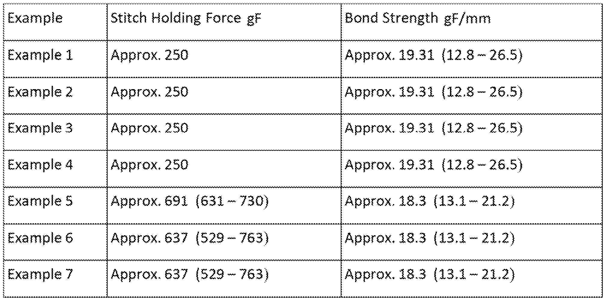
- Stitch retention was measured using the methods specified in IS0719S yielding values of 250 gF.
- Bond strength was measured using the methods specified in ASTM D903 yielding values of 19.31 gF/mm (12.8- 26.5) gF/mm.
- An inner layer formed from a graft of Material A was prepared by slicing the graft longitudinally and winding it onto a mandrel such that the originai iongitudinal axis of the graft was perpendicular to the longitudinal axis of the mandrei ⁇ and hence the resulting covered medical device).
- the layer was 0.115 mm plus or minus 0.035 mm thick.
- a stent with a 26 mm expanded diameter was mounted on top of the inner layer.
- An outer layer formed from a graft of Material A was prepared by slicing the graft Iongttudinaily and winding it onto the mandrel on top of the stent such that the original iongitudinal axis of the graft was perpendicular to the longitudinal axis of the mandrei (and hence the resulting covered medical device).
- the layer was 0.115 mm plus or minus 0.035 mm thick.
- the entire assembly was wrapped with PTFE tape and heated to laminate the layers to each other, around the struts of the stent.
- the entire assembly was heated at 360 °C for 30 minutes.
- An inner layer formed from a graft of Material A was prepared by slicing the graft Iongttudinaily and winding it onto a mandrel such that the original longitudinal axis of the graft was perpendicular to the iongitudinai axis of the mandrei (and hence the resulting covered medical device).
- the layer was 0.115 mm plus o minus 0.035 mm thick,
- a non-cylindrical device was mounted on top of the inner iayer.
- An outer layer formed from a graft of Material A was prepared by slicing the graft iongttudinaily and winding it onto the mandrel on top of the stent such that the original longitudinal axis of the graft was perpendicular to the longitudinal axis of the mandre! (and hence the resulting covered medical device).
- the layer was 0.115 mm plus or minus 0,035 mm thick.
- Stitch retention was measured using the methods specified in iSQ7138 yielding values of 250 gF.
- Bond strength was measured using the methods specified in ASTM D903 yielding values of 19.31 gF/mm (12.8- 26.5) gF/mm,
- An inner iayer formed from a graft of Material A was prepared by slicing the graft longitudinally and winding it onto a mandrel such that the original longitudinal axis of the graft was perpendicular to the longitudmai axis of the mandrel (and hence the resulting covered medicai device).
- the iayer was 0.115 mm pius or minus 0.035 mm thick,
- a mid-layer formed from a graft of Materia! A was prepared by slicing the graft longitudinally. The iayer was subjected to a caiendering process comprising Saying a piece of the graft materia! onto a calendering pad so that it lays vertical. Next, a second calendering pad was place over the materia! forming a stack. Then, the stack was piaced into a calendering machine and a calendering pin or member was placed on top of the stack. A calendering cycle (two rolls per pressure setting starting at 20 psi and ending at 60 psi with five pressure changes) was then initiated. The caiendering cycie was repeated until a desired thickness of 0.025 mm was reached.
- This calendered material was wound over the inner iayer materia! such that the original longitudinal axis of the graft was perpendicular to the longitudinal axis of the mandrel.
- a stent with a 26 mm expanded diameter was mounted on top of the inner layer.
- An outer Iayer formed from a graft of Material A was prepared by slicing the graft longitudinally and winding it onto the mandrel on top of the stent such that the original longitudinal axis of the graft was perpendicular to the longitudinal axis of the mandrel (and hence the resulting covered medical device).
- the layer was 0.115 mm plus or minus 0,035 mm thick.
- the entire assembly was wrapped with PTFE tape and heated to laminate the layers to each other, around the struts of the stent.
- the entire assembly was heated at 360 °C for 30 minutes.
- An inner layer formed from a graft of Material A was prepared by slicing the graft longitudinally and winding it onto a mandrel such that the original longitudinal axis of the graft was perpendicular to the iongitudinal axis of the mandrel (and hence the resulting covered medicai device).
- the iayer was 0.065 mm pius or minus 0.025 mm thick,
- a mid-layer formed from a graft of Materia! A was prepared by slicing the graft longitudinally. The iayer was subjected to a caiendering process comprising laying a piece of the graft materia! onto a calendering pad so that it lays vertical. Next, a second calendering pad was place over the materia! forming a stack. Then, the stack was placed into a calendering machine and a calendering pin or member was placed on top of the stack. A calendering cycle (two rolls per pressure setting starting at 20 psi and ending at 60 psi with five pressure changes) was initiated, and the calendering cycle repeated until a desired thickness of 0,001 inches was reached. OOB83 A stent with a 26 mm expanded diameter was mounted on top of the inner layer,
- An outer iayer formed from a graft of Materia! A was prepared by slicing the graft longitudinally and winding it onto the mandrel on top of the stent such that the original longitudinal axis of the graft was perpendicular to the iongitudinal axis of the mandrei (and hence the resulting covered medical device).
- the Iayer was 0.065 mm plus or minus 0.025 mm thick.
- 3 ⁇ 4e entire assembly was wrapped with PTFE tape and heated to laminate the layers to each other, around the struts of the stent. The entire assembly was heated at 360 for 30 minutes.
- An inner layer formed from a graft of Material A was prepared by slicing the graft longitudinally and winding it onto a mandrel such that the originai longitudinal axis of the graft was perpendicular to the longitudinal axis of the mandrel ⁇ and hence the resulting covered medical device).
- the layer was 0.065 mm plus or minus 0.025 mm thick.
- a mid-layer formed from a graft of Materia! A was prepared by slicing the graft longitudinally. The iayer was subjected to a calendering process comprising laying a piece of the graft material onto a calendering pad so that it lays vertical. Next, a second calendering pad was place over the material forming a stack. Then, the stack was placed into a calendering machine and a calendering pin or member was piaced on top of the stack, A calendering cycle (two rolls per pressure setting starting at 20 psi and ending at 60 psi with five pressure changes) was initiated. The calendering cycle was repeated until a desired thickness of 0.0254 mm was reached.
- An outer iayer formed from a graft of Material A was prepared by slicing the graft longitudinally and winding it onto the mandrel on top of the stent such that the original iongitudinal axis of the graft was perpendicular to the Iongitudinal axis of the mandrei (and hence the resulting covered medical device).
- the iayer was 0,065 mm pius or minus 0,025 mm thick.
- the entire assembiy was wrapped with PTFE tape and heated to laminate the layers to each other, around the struts of the stent. The entire assembiy was heated at 360 for 30 minutes.
- Stitch retention was measured using the methods specified in iS0719S yielding values of 637 gF 529 - 763 ⁇ gf.
- Bond strength was measured using the methods specified in AST D903 yielding values of 18.3 gF/mm (13.1-21,2) gF/mm.
- An inner layer formed from a graft of Material A was prepared by slicing the graft longitudinally and winding it onto a mandrei such that the original longitudinal axis of the graft was perpendicular to the iongitudina! axis of the mandrel ⁇ and hence the resulting covered medical device).
- the layer was 0.065 mm plus or minus 0.025 mm thick.
- a mid-layer formed from a graft of ateriai A was prepared by slicing the graft longitudinally.
- the materia! was subjected to a caSendering process comprising Saying a first piece of the graft material onto a calendering pad so that it iays vertical.
- a second layer of material was placed over the first piece of graft material so that the orientation direction of the first layer of graft material was perpendicular to the second layer of graft material.
- An outer layer formed from a graft of Material A was prepared by slicing the graft longitudinally and winding it onto the mandrel on top of the stent such that the original Iongitudina! axis of the graft was perpendicular to the longitudinal axis of the mandrel (and hence the resulting covered medical device).
- the layer was 0.065 mm plus or minus 0.025 mm thick.
- the entire assembiy was wrapped with PTFE tape and heated to laminate the layers to each other, around the struts of the stent. The entire assembiy was heated at 360 for 30 minutes.
- An inner layer formed from a graft of Material A was prepared by slicing the graft longitudinally and winding it onto a mandrei such that the original longitudinal axis of the graft was perpendicular to the longitudinal axis of the mandrel ⁇ and hence the resulting covered medicai device).
- the iayer was 0.065 mm p!us or minus 0.025 mm thick.
- a mid-layer formed from a graft of Material A was prepared by slicing the graft longitudinally.
- the materia! was subjected to a calendering process comprising laying a first piece of the graft material onto a calendering pad so that it iays vertical.
- a second iayer of material was placed over the first piece of graft material so that the orientation direction of the first layer of graft material made an angle of 45 degrees with the second Iayer of graft material. This is caiied 2- iayer, 45degree calendering.
- a second caiendering pad was place over the materials forming a stack.
- a calendering cycle (two roils per pressure setting starting at 20 psi and ending at 60 psi with five pressure changes) was initiated, and repeated until a desired thickness of 0.001 inches was reached.
- An outer iayer formed from a graft of Materia! A was prepared by slicing the graft longitudinally and winding it onto the mandrel on top of the stent such that the original longitudinal axis of the graft was perpendicular to the longitudinal axis of the mandrei (and hence the resulting covered medical device).
- the iayer was 0.065 mm pius or minus 0.025 mm thick.
- the entire assembly was wrapped with PTFE tape and heated to laminate the layers to each other, around the struts of the stent. The entire assembly was heated at 360 for 30 minutes.
- This medicai device was prepared substantially the same way as the medicai device of Exampie 8.
- the difference between this exampie and Example 8 is that in this exampie the inner layer was wound onto the mandrei such that the original Songitudinal axis of the graft was parallel to the Songitudinal axis of the mandrei (and hence the resulting covered medicai device).
- the inner and outer layers were each 0.065 mm plus or minus 0.025" thick.
- This medical device was prepared substantialiy the same way as the medical device of Example 9.
- the difference between this example and Example 9 is that in this exampie the inner layer was wound onto the mandrei such that the original longitudinal axis of the graft was parallel to the longitudinal axis of the mandrei (and hence the resulting covered medical device).
- the inner and outer layers were each 0.065 mm pius or minus 0.025" thick.
- Stitch retention was measured using the methods specified in SS07198 yielding values of 452 gF (444 - 460) gF.
- Bond strength was measured using the methods specified in ASTM D903 yielding vaiues of 18.3 gF/mm (13.1-21.2) gF/mm, Example 12
- This medicai device was prepared substantially the same way as the medicai device of Example 10.
- the difference between this exampie and Example 10 is that in this example the outer layer was formed from a thicker graft.
- the outer layer was 0,115 mm pius or minus 0,035" thick.
- the inner layer was 0.065 mm plus or minus 0.025 mm thick,
- Stitch retention was measured using the methods specified in SS07198 yielding values of 502 gF (497 - 507) gF.
- Bond strength was measured using the methods specified in AST D903 yielding values of 18.3 gF/mm ⁇ 13.1-21.2) gF/mm.
- This medicai device was prepared substantially the same way as the medicai device of Exampie 8.
- the difference between this exampie and Exampie 8 is that, in this example, the outer layer was formed from a thicker graft that was wound onto the mandrel on top of the stent such that the original longitudinal axis of the graft was parallel to the longitudinal axis of the mandrel (and hence the resulting covered medical device).
- the outer layer was 0.115 mm pius or minus 0,035 mm thick.
- the inner layer was 0,065 mm plus or minus 0,025 mm thick.
- Stitch retention was measured using the methods specified in IS0719S yielding values of 502 gF (497 - 507) gF.
- Bond strength was measured using the methods specified in ASTM D903 yielding values of 18.3 gF/mm (13.1-21.2) gF/mm.
- This medical device was prepared substantially the same way as the medical device of Exampie 13. The difference between this example and Exampie 13 is that, in this exampie, the mid-layer was formed using textured calendering pads.
- Stitch retention was measured using the methods specified in IS07198 yielding values of 502 gF (497 - 507) gF.
- Bond strength was measured using the methods specified in ASTM D903 yielding values of 18.3 gF/mm (13.1-21.2) gF/mm.
- This medical device was prepared substantially the same way as the medical device of Exampie 13, The difference between this example and Exampie 13 is that, in this exampie, the mid-layer was strategically placed so as to improve the bond between the inner and outer iayers at the laser cut point.
- This medicai device was prepared substantially the same way as the medicai device of Exampie 15. The difference between this example and Exampie 15 is that, in this example, the device included a skirt at the end thereof, which is an extension of the inner, outer, and ca!endered material.
- This medicai device was prepared substantially the same way as the medical device of Example 16, The difference between this example and Example 16 is that, in this example, the skirt at the end of the device was reinforced with two layers of calendered material oriented 90°.
- This medical device was prepared substantially the same way as the medical device of Example 13. The difference between this example and Example 13 is that instead of a stent, a non-cyitndricaS medicai device with a 26 mm expanded diameter was mounted on top of the inner layer,
Landscapes
- Health & Medical Sciences (AREA)
- Public Health (AREA)
- Animal Behavior & Ethology (AREA)
- Heart & Thoracic Surgery (AREA)
- General Health & Medical Sciences (AREA)
- Vascular Medicine (AREA)
- Life Sciences & Earth Sciences (AREA)
- Veterinary Medicine (AREA)
- Engineering & Computer Science (AREA)
- Cardiology (AREA)
- Biomedical Technology (AREA)
- Epidemiology (AREA)
- Surgery (AREA)
- Oral & Maxillofacial Surgery (AREA)
- Transplantation (AREA)
- Chemical Kinetics & Catalysis (AREA)
- Chemical & Material Sciences (AREA)
- Prostheses (AREA)
- Media Introduction/Drainage Providing Device (AREA)
- Materials For Medical Uses (AREA)
- Manufacturing & Machinery (AREA)
Abstract
Stent, stent coverings, and methods of making medical devices useful in vascular valves are disclosed. In particular, polymer film coverings for stents such as that usable for valves or aortic valves are disclosed. Such stent coverings include layered, oriented, calendered polymer films that may be anisotropically aligned or calendered.
Description
EPTFE VALVES
PRIORITY
[00013 This application claims priority to U.S. Application No, 61/937,235,, filed February 7, 2014, which is incorporated by reference in its entirety into this application.
BACKGROUND
[0002] Aortic stenosis is a common cause of valvular heart, its incidence increases exponentially in older patients. Fibrosis, degeneration and subsequent calcification are no longer believed to be passive or purely degenerative in nature. Over time, as fibrosis and calcification worsens, valve leaflets become increasingly rigid, restricting their ability to open. This type of decreased function impedes blood flow through the heart causing hear failure, for example. Other causes of deformed and stenotic aortic valvular Sesions include rheumatic heart disease, as well as congenital heart disease.
[0003] Heart valves change from their structure at birth driven In part by the norma! dynamic daily stresses. But stenotic changes usually do not harm a person for many decades unless infection causes the stenosis. While the person lives with these changes unhampered for a long time, when intervention does become needed, the person has often become a poor surgical candidate for typical heart valve replacement using open heart techniques,
[0004] Minimally invasive valvuloplasty techniques can dilate stenosed valves using catheter balioons and catheter-placed replacement heart valves. During this procedure, a catheter having a deflated bailoon is percutaneousiy inserted into a vein or artery and advanced until the balloon is positioned within the heart valve needing treatment. The balloon is then inflated to dilate the diseased valve opening, disrupting the rigid sheets of calcium permitting placement of the replacement valve. After the new valve has been placed, the bal!oon is deflated and removed from the patient's cardiovascular system.
[0005] Catheter-based cardiovascular procedures include TAVi (transcatheter aortic valve implantation), TAVR (transcatheter aortic valve replacement), and PAVft (percutaneous aortic valve replacement) devices.
[0006] Percutaneous aortic valve replacement (PAVR), transcatheter aortic va!ve implantation {TAVi}, or transcatheter aortic vaive replacement (TAVR) are similar procedures for aortic va!ve replacement through blood vessels associated with the target vaive. These procedures as opposed to valve replacement by open heart surgery are considered minimaily invasive procedures. These procedures deliver the replacement vaive using one of several access methods such as transfemora! (in the upper leg), transapkal {through the waii of the heart), subclavian (beneath the collar bone) and direct aortic (through a minimaily invasive surgical incision into the aorta}.
SUMMARY
[0007] The embodiments described in this disclosure relate to polymer film coverings for stents such as for valves or aortic valves. Depending on the embodiment, the polymer fiims may be a isotropicaiSy aligned or calendered,
[0008] Some embodiments include an inner polymer layer comprising an anisotropic polymer and havin an orientation direction; a mid-layer polymer film comprising an anisotropic polymer and having an orientation direction at an inner orientation angle to the inner polymer film; and an outer poiymer film comprising an anisotropic polymer and having an orientation direction at an outer orientation angle to the mid-layer polymer film; and a medical device disposed between the mid-layer film and the outer poiymer film, in these or other embodiments, 0 is less than or equai to the inner orientation angle, which is iess than or equai to 90 or 80 is less than or equal to the inner orientation angle, which is less than or equal to 90. in these or other embodiments, 0 is less than or equal to the outer orientation angie, which is iess than or equal to 90 or 80 is iess than or equal to the outer orientation angle, which is less than o equai to 90,
[00093 The orientation of the polymer chains in some embodiments is aiigned with the longitudinal axis of the medical device at an angie of 0≤ angle≤ 90. That is the polymer chains aiign parallel, perpendicular, or any angle in between.
[00103 ^ some embodiments, the poiymer is ePTFE or a poiymer exhibiting a node-and- fsbri! structure. Medical device embodiments include one or more of the oriented polymer layers
comprising materia! exhibiting unilaterally oriented fibrils. In some embodiments, the polymer comprises elemental carbon. In various embodiments, the polymer films of medical devices have stitch retention range of 250-800 gF or 452-691 gF.
[00113 Additionally, embodiments of the invention include methods of making a medica! devic comprising the steps of mounting an inner polymer film on a mandrei; forming a calendered mid-layer film; mounting the mid-layer film on the inner polymer film; mounting a stent on the mid-layer film; mounting an outer polymer film on the stent; followed by heating to a temperature.
[0012] in some of these embodiments, forming comprises providing a caiendaring machine comprising at Ieast two members; one member configured to press against and roll along the other member during a cycle; providing an oriented polymer iayer having an orientation direction; arranging one oriented polymer layer on a slip; covering the oriented polymer layer with a second slip; installing the slips in the calendaring machine; and cycling the machine. In these or other embodiments, the orientation is substantially perpendicular or substantially parallel to a longitudinal axis of the medical device.
DESCRIPTION; OF THE FIGURES
[00133 Figure 1 is a schematic view of a portion of the valve of this invention.
[00143 Figure 2 is a schematic view of an outer layer of a valve of this invention.
[00153 Figure 3 is a schematic vie of an inner iayer of a valve of this invention,
[00163 Figure 4 is a schematic view of a stent or of a stent Iayer of this invention,
[0017] Figure 5 is a schematic view of the mid iayer of a valve of this invention.
[0018] Figure 6 is a view of polymer layers showin the definition of an orientation angle.
[00193 Figure 7 is a flowchart showing a method of making a medical device.
DETAILED DESCRIPTION
[0020] The foiiowing description of several embodiments describes non-limiting examples that further illustrate the invention, No titles of sections contained herein, including those appearing above, are limitations on the invention, but rather they are provided to structure the illustrative description of the invention that is provided by the specification,
[00213 Unless defined otherwise, all technical and scientific terms used in this document have the same meanings that one skilled in the art to which the disclosed invention pertains would ascribe to them. The singular forms "a", "an", and "the" include plural referents unless the context clearly indicates otherwise. Thus, for example, reference to "fluid" refers to one or more fluids, such as two or more fluids, three or more fluids, etc. Any mention of an element includes that element's equivalents as known to those skilled in the art.
[ΟΟ223 The features, aspects, and advantages of the invention will become more apparent from the following detailed description, appended claims, and accompanying drawings,
[00233 Figure 1 depicts a cross-sectional schematic view cut through the longitudinal axis of a medical device 50 of the current invention, Medical device 50 comprises a stent 400 or stent-!ske structure in which at least one polymer film 100, 200, 300 is disposed radially inward of stent 400 and at least one poiymer film 500 is disposed radtaiiy outward of stent 400. One or more of the polymer film layers 100, 200, 300, or 500 comprise or can come from an oriented polymer film,
[0024] Turning now to Figure 2, the figure shows a schematic view of outer layer 500 of medsca! device 50. in this figure, a region of outer layer 500 is shown. For simplicity's sake, iayer 500 is depicted as being fiat rather than cylindrical. Vector L represents the medical device's longitudinal axis direction, As can be seen in the overly simplified depiction, poiymer chains 501 tend to run in a direction perpendicular to vector L and hence to the device's longitudinal axis, in the cylindrical shape, the poiymer chains would wrap around the medical device longitudinal axis, such that any given polymer chain would have generally the same longitudinal position along the polymer chain with respect to the medical device.
[00253 Turning now to Figure 3, the figure shows a schematic view of inner iayer 100 of medicai device 50. In this figure, a region of inner Iayer 100 is shown. For simplicity's sake, iayer 100 is depicted as being fiat rather than cylindrical. Vector L represents the medical device's iongitudinai axis direction. As can be seen in the overly simplified depiction, polymer chains 101 tend to run in a direction perpendicular to vector I and hence to the device's iongitudinai axis, in the cylindrical shape, the poiymer chains would wrap around the medical device iongitudinai axis, such that any given poiymer chain wouid have generally the same longitudinal position along the poiymer chain with respect to the medical device.
[0026] Whiie figures 2 and 3, depict an embodiment in which poiymer chains 101 and 501 tend to run in a direction perpendicuiar to vector L, various other embodiments exist in which the orientation of inner Iayer 100, outer layer 500, or both have polymer chains 101 and 501 that tend to run in a direction perpendicular to vector L or embodiments where the polymer chains of either iayer tend to run in a direction skew to vector L For example, the angle of polymer chains 101 and 501 may be any angle between perpendicuiar and parallel to vector L
[0027] Figure 4 depicts the stent or lattice-work structure 405 of stent 400. Struts 410 are shown, in this figure, a region of the stent or lattice-work structure 405. For simplicity's sake, structure 405 is depicted as being fiat rather than cylindrical. For completeness sake, vector L is indicated in figure 4.
[0028] Figure 5 depicts a mid-layer embodiment of the medicai device 50. in this embodiment, the mid-layer comprises two layers 200, 300 that have polymer chain orientations 201, 301 in directions different from each other. Generally, the angie between the two orientation vectors is ca!led an orientation or alignment angle. This orientation angle, , is defined in Figure 6. As can be seen in the figure, layer 1 (600) exhibits an orientation vector direction 601. And layer 2 {650} exhibits an orientation vector or direction 651. Angle a {675} is the angie between the orientation vectors.
[00293 The various layers of medical device 50 can have different compositions. Some embodiments employ a base material that is any one or any combination of expanded
fluoroethy!polypropylene (ePTFE), polyamides, po!yimides, silicones, f!uoroethylpolypropyiene
{FEP), polypropyifluorinated amines (PFA), or other fSuorinated polymers.
[00303 Some polymer materials usefui in various embodiments of the invention include those described above, as weii as anisotropic versions of those.
[0031] AH materials useful in intervention monuments have thicknesses that range from 0.001 to 0.009 inches.
[00323 ¾e stent portion can assume any known structure seen in the medical device arts. Stent-like devices useful in invention devices are any of those generaily known to be usefui in TAVi {transcatheier aortic vaive implantation},, TAVR (transcatheter aortic valve replacement), or PAVR {percutaneous aortic vaive replacement} devices,
[00333 Percutaneous aortic valve replacement (PAVR), transcatheter aortic vaive implantation (TAVi), or transcatheter aortic vaive replacement {TAVR} are similar procedures for aortic vaive replacement through blood vessels associated with the target vaive. These procedures as opposed to valve replacement by open heart surgery are considered minimally invasive procedures. These procedures deliver the replacement vaive using one of several access methods such as transfemorai {in the upper leg), transapical (through the waii of the heart}, subclavian {beneath the coiiar bone) and direct aortic {through a minimally invasive surgical incision into the aorta).
[00343 Some embodiments employ examples of the above that are stainless steel or nitinoi scaffolds (stents), sometimes with a biologicai valve attached directiy to the metal structure or to a textile skirt sutured to the lower portion of the device, inner diameters for stent-like devices range from 20mm to 45mm.
[00353 Exemplary construction of an exemplary stent graft, including exemplary ePTFE film production is provided herein.
[0036] Methods and techniques for expanding polytetrafiuoroethylene have been known for many years. One of the earliest disciosures containing a discussion of such methods and resultant products is found in Japanese Patent No. 13,560/67 which was filed Nov. 1, 1963 and officially published on Aug, 1, 1967.
[0037] The basic process for expanding polytetrafluoraethyfene is quite simple: The material is extruded into the desired geometric configuration. The materia! is then heated at a temperature below the sintering temperature of 327° C and physically stretched or expanded along at ieast one axis. The expanded member is sintered by brief exposure to temperatures above 327* C, thereby crystallizing the expanded structure. As the raw extrudate is stretched, the non-porous poiytetrafluoroethyiene separates into solid nodes of polytetrafiuoroethylene which remain structurally interconnected by polytetrafiuoroethylene fibrils that are drawn from the nodes during expansion, Node size and distribution in the final product is adversely affected by very rapid expansion, uneven expansion, insufficient heating, non-uniform heating/ and irregularly distributed expansion forces. The distance between nodes is directly proportional to the extent to which the extrudate has been expanded. When PTFE is properly expanded along one axis, virtually no dimensional changes are observed in the orthogonal direction. The expansion causes PTFE chains to orient in the expansion direction.
[00383 It has been found that the average internoduiar distance, as measured aiong the expansion direction, must fall within a relatively narrow range of values, between approximately 6 and SO microns. One of ordinary skill in the art understands, the term "average" when used in conjunction with internoduiar distance and node size cannot be used or interpreted with statistical precision; rather, the term is intended to connote a nominal or typical dimension derived from a broad sample. By way of example, where the average internoduiar distance is said to be 30 microns, it wouid be expected that some of the nodes would be separated by only a few microns while others might be separated by 90 or 100 microns.
[00393 Various types of ePTFE are useful in embodiments of the invention. One type is referred to in this disclosure as Type-A ePTFE. This is a material prepared from carbon impregnated, unsintered PTFE.
[0040] This material has a node-and-fibri! structure that is uniaxiaily oriented. Thus, Type-A ePTFE is a PTFE comprising elemental carbon exhibiting a node-and-fibri! structure wherein the fibrils are substantially uniaxiaily aligned. Type-A material is also referred herein at MAT. A,
[0041] Another type of material is referred to in this disclosure as Type-B ePTFE. This is a material prepared from unentered PTFE. This materia! has a node-and-fibrii structure that is unilaterally oriented by expansion of the PTFE. Thus, Type-B ePTFF. is a PTFE exhibiting a node-and- fibri! structure wherein the fibri!s are substantially unilaterally aligned. Type-B material is also referred herein as MAT, 8.
[0042] As those of ordinary skill in the art recognize, an oriented polymer film is a polymer film in which individual po!ymer chains align in one or more specific directions. The poiymer chains may align either be cause of their overa!l physical or chemical nature or because of processing steps that transform more or less randomiy aligned polymer chains into chains that exhibit greater a!ignment directionality. For examp!e, uniaxialiy oriented poiymer chains align preferentiaiSy along one general direction. Similarly, biaxialiy oriented polymer chains align preferentially along two directions. Regardless of how or why the poiymer chains align, a polymer with a specific chemical composition is a different material than a poiymer with a similar chemica! composition but with greater polymer chain alignment,
[0043] As one of ordinary skill in the art wili recognize, this orientation does not mean that the poiymer chains completely align. The orientation shows up as a distribution of chains with a non-random alignment of the chains. Some oriented polymers exhibit a structure akin to the node- and-fibri! structure discussed above for ePTFE while other polymers exhibit structures that were derived from node-and-fibrii structures. Yet others have no relationship to node-and-fibri! structures.
[0044] A random alignment of po!ymer chains can aiso be called an isotropic arrangement. That is, a buik sample of polymer chains with an isotropic orientation would exhibit chains substantially aligned equally in ail directions. Conversely, a bulk sample of poiymer chains can be anisotropicai!y aligned or oriented and would therefore exhibit chain alignment that is not
substantially equal in all directions. This disclosure refers to materials with an anisotropic distribution of chain directions as anisotropic polymers. "Anisotropic polymers" are polymers in which polymer chains align more in one direction than in others.
[00 5J For purposes of this disclosure, orientation or alignment directions of the polymer chains are referenced against the medical device's longitudinal axis, which is present in all substantially cylindrical objects such as a stent or valve. A polymer orientation described as perpendicular (perp.) to the longitudinal axis would exhibit an alignment that is locally perpendicular to the longitudinal axis. Note that this local arrangement typically results in polymer chains tending to take an arcuate path around all or a portion of the cylindrical structure. Relatediy, parallel (para,) orientation means that the chains tend to run in a direction similar to that of the stent's longitudinal axis.
[0046] Both the parallel and the perpendicular directions are, of course, subject to more specific definition throughout this disciosure and are subject to the knowledge of one of ordinary skill in the art,
[0047] As discussed above, medical device 50 comprises at least inner and outer layers and optionally a mid-layer, in some embodiments, a polymer layer is calendered before it becomes part of an invention device.
[0048J Calendering is a process of treating a polymer film by exposing it to one or more pressure applications. These pressure applications use a mandrel plus a fiat plate or a pad pius a flat plate to exert high pressure along the length of the film. In practice, the pressure application begins at one end of the film and progresses along the film from one end to the other. In some cases, calendering acts like a rolling pin flattening a pie crust. The film arrangement is such that pressure is applied along the z-axis considering the plane of the film as the x/y-plane. In some embodiments, a single film was calendered. In other embodiments, two films were calendered with one film layer, either partially or completely, on top of the other film layer, sometimes fusing the films together. The orientation angle between chains and such films ranges from 0 to 90° or SO to 9CT, in some embodiments.
[0049] in some embodiments, calendering permanently or semipermanently reduces the film's thickness, in some embodiments, calendering obscures or destroys the node-and-fibril structure.
[0050J Figure 7 depicts a method for producing medical device 50, At step 700, mounting a polymer film occurs first. A film of a polymer is mounted on a mandrel, Different embodiments may employ isotropic or anisotropic polymer films, in the case of anisotropic polymer films,, the orientation direction of the film can be arranged so that it is perpendicular, parallel, or skew to the longitudinal axis of the medical device by properly manipulating the film as it is mounted on the mandrel. Any number of inner iayer films can be used.
[0051] At step 710, mounting a mid-layer polymer film 205 occurs next. Mid-layer poiymer film 205 is mounted on the mandrel on top of inner layer 100, Mid-layer film 205 is typically mounted with similar constraints to those described for inner layer 100. In some embodiments of this mounting step, mid-iayer film 205 covers inner layer 100; in other embodiments, mid-layer film 205 covers part of inner iayer 100 film 100.
[0052] At step 720, mounting stent 400 on the mandrei occurs next. The nature of the stent was discussed above.
[00533 Ultimately, a step 730 of mounting outer poiymer film layer 500 on the mandrel occurs. Outer polymer film 500 may completely cover stent 400 or may cover part of stent 400.
[00543 At step 740,, the construction is placed under light to moderate, substantially uniform, pressure, in some embodiments, this construction is firmly wrapped with an inert tape such as PTFE to provide the pressure, among other things.
[00553 At step 750, the construction is heated to fuse polymer layers 100, 200, 300, 500 to each other, to stent 400, and around struts 410,
[00563 At step 760, after heating, the medical device is removed from the mandrei, which includes removing any inert tape,
[0057] !n use, the medical device is delivered percutaneousiy through a patient's vasculature until the desired area for implanting the valve is reached. The decrease In valve thickness for medtcai device 50 allows for a decrease in the overaii thickness of the delivery system and hence the diameter of the entry point. At that point, the clinician delivers the device by manipulation of a handle outside of the patient.
EXAMPLES

Orientation
Example 14 1 layer of MAT. A/Perp. Textured 2 layer 90* Cal. 1 layer of MAT. A/Para.
MAT. A/Perp.
Exam Se 15 1 layer of MAT. A/Perp. 2 layer 90° CaS. MAT. 1 layer of MAT. A/Para.
A/Perp.
Example 16 1 layer of MAT. A/Perp. 2 layer 90° Cal, MAT. A/Perp. 1 layer of MAT. A/Para.
Example 17 1 layer of MAT. A/Perp. 2 layer 90° Cal. MAT. A/Perp. 1 layer of MAT. A/Para,
Example 18 1 layer of MAT. A/Perp. 2 layer 90° Cai. MAT. A/Perp. 1 layer of MAT. A/Para.
Example 19 1 layer of MAT. A/Perp. 2 layer 90° Cal. MAT. A/Perp. 1 layer of MAT. A/Para.
[00583 MAT. A is the Type-A ePTFE, MAT. B is the Type-B ePTFE, Perp. is an orientation perpendicular to the longitudinal axis of the medical device, Para, is an orientation parallel to the iongitudina! axis of the medical device, and Cal. indicates that the disclosed layer was calendered.
Example 8 Approx. 549 {515 - 591} Approx, 18.3 {13.1 - 21.2)
Example 9 Approx. 606 {473™ 700) Approx. 18.3 (13,1 - 21.2)
Example 10 Approx, 502 (497 - 507) Approx. 18.3 (13.1 - 21.2)
Example 11 Approx. 452 (444 ~ 460) Approx. 18.3 (13.1 - 21.2 )
Example 12 Approx. 502 {497 - 507) Approx. 18.3 {13.1 - 21,2)
Example 13 Approx. 502 (497 - 507) Approx. 18.3 (13,1 - 21,2)
Example 14 Approx. 502 (497 - 507) Approx. 18,3 (13.1 - 21.2)
Example 15 Approx. 502 (497 ~ 507) Approx, 18,3 (13.1 - 21.2 )
Example 16 Approx. 502 (497 - 50?) Approx. 18.3 (13.1 - 21.2)
Exam le 17 Approx. 502 (497 - 507) Approx. 18.3 (13.1 - 21,2)
Example 18 Approx. 502 {497 - 507) Approx. 18.3 {13.1 - 21.2}
Example 19 Approx. 502 (497 - 507) Approx. 18,3 (13.1 - 21.2)
Example 1
[00593 An inner layer formed from a graft of Material was prepared by slicing the graft longitudinally and winding it onto a mandre! such that the original longitudinal axis of the graft was perpendicular to the longitudinal axis of the mandrel {and hence the resulting covered medical device). The layer was 0.115 mm plus or minus 0.035 mm thick.
[00603 A stent with a 26 mm expanded diameter was mounted on top of the Inner layer.
[00613 An outer layer formed from a graft of Material A was prepared by slicing the graft longitudinally and winding it onto the mandrel on top of the stent such that the original
longitudinal axis of the graft was perpendicular to the longitudinal axis of the mandrel (and hence the resulting covered medical device). The iayer was 0.115 mm pius or minus 0,035 mm thick.
[0062] The entire assembly was wrapped with PTFE tape and heated to laminate the layers to each other, around the struts of the stent. The entire assembly was heated at 360° C for 30 minutes.
[00633 Stitch retention was measured using the methods specified in iS07138 yieldi g values of 250 gF. Bond strength was measured using the methods specified in ASTiVl D903 yielding values of 19.31 gF/mm (12.8- 26.5 gF/mm),
Example 2
[0064] An inner iayer formed from a graft of Material A was prepared by slicing the graft longitudinally and winding two layers of it onto a mandrel such that the original longitudinal axis of the graft was perpendicular to the iongitudtnai axis of the mandrel (and hence the resulting covered medical device). Each layer was 0.115 mm plus or minus 0.035 mm thick.
[0065] A stent with a 26 mm expanded diameter was mounted on top of the inner layer,
[00663 An outer Iayer formed from a graft of Materia! A was prepared by slicing the graft longitudinally and winding 4 layers of it onto the mandrel on top of the stent such that the original longitudinal axis of the graft was perpendicular to the longitudinal axis of the mandrel (and hence the resulting covered medical device). Each iayer was 0.115 mm pius or minus 0.035 mm thick.
[0067] The entire assembly was wrapped with PTFE tape and heated to laminate the layers to each other, around the struts of the stent. The entire assembly was heated at 360 °C for 30 minutes.
[0068] Stitch retention was measured using the methods specified in IS0719S yielding values of 250 gF. Bond strength was measured using the methods specified in ASTM D903 yielding values of 19.31 gF/mm (12.8- 26.5) gF/mm.
Example 3
[00693 An inner layer formed from a graft of Material A was prepared by slicing the graft longitudinally and winding it onto a mandrel such that the originai iongitudinal axis of the graft was perpendicular to the longitudinal axis of the mandrei {and hence the resulting covered medical device). The layer was 0.115 mm plus or minus 0.035 mm thick.
[0070] A stent with a 26 mm expanded diameter was mounted on top of the inner layer.
[00713 An outer layer formed from a graft of Material A was prepared by slicing the graft Iongttudinaily and winding it onto the mandrel on top of the stent such that the original iongitudinal axis of the graft was perpendicular to the longitudinal axis of the mandrei (and hence the resulting covered medical device). The layer was 0.115 mm plus or minus 0.035 mm thick.
[0072] The entire assembly was wrapped with PTFE tape and heated to laminate the layers to each other, around the struts of the stent. The entire assembly was heated at 360 °C for 30 minutes.
[00733 Stitch retention was measured using the methods specified in SS0719S yielding values of 250 gF. Bond strength was measured using the methods specified in ASTM D903 yielding values of 19.31 gF/mm (12.S- 26.5) gF/mm.
Example 4
[0074] An inner layer formed from a graft of Material A was prepared by slicing the graft Iongttudinaily and winding it onto a mandrel such that the original longitudinal axis of the graft was perpendicular to the iongitudinai axis of the mandrei (and hence the resulting covered medical device). The layer was 0.115 mm plus o minus 0.035 mm thick,
[00753 A non-cylindrical device was mounted on top of the inner iayer.
[00763 An outer layer formed from a graft of Material A was prepared by slicing the graft iongttudinaily and winding it onto the mandrel on top of the stent such that the original
longitudinal axis of the graft was perpendicular to the longitudinal axis of the mandre! (and hence the resulting covered medical device). The layer was 0.115 mm plus or minus 0,035 mm thick.
[00773 The entire assembly was wrapped with PTFE tape and heated to laminate the layers to each other, around the struts of the stent. The entire assembly was heated at 360 °C for 30 minutes.
[0078] Stitch retention was measured using the methods specified in iSQ7138 yielding values of 250 gF. Bond strength was measured using the methods specified in ASTM D903 yielding values of 19.31 gF/mm (12.8- 26.5) gF/mm,
Example 5
[0079] An inner iayer formed from a graft of Material A was prepared by slicing the graft longitudinally and winding it onto a mandrel such that the original longitudinal axis of the graft was perpendicular to the longitudmai axis of the mandrel (and hence the resulting covered medicai device). The iayer was 0.115 mm pius or minus 0.035 mm thick,
[00803 A mid-layer formed from a graft of Materia! A was prepared by slicing the graft longitudinally. The iayer was subjected to a caiendering process comprising Saying a piece of the graft materia! onto a calendering pad so that it lays vertical. Next, a second calendering pad was place over the materia! forming a stack. Then, the stack was piaced into a calendering machine and a calendering pin or member was placed on top of the stack. A calendering cycle (two rolls per pressure setting starting at 20 psi and ending at 60 psi with five pressure changes) was then initiated. The caiendering cycie was repeated until a desired thickness of 0.025 mm was reached.
[0081] This calendered material was wound over the inner iayer materia! such that the original longitudinal axis of the graft was perpendicular to the longitudinal axis of the mandrel.
[00323 A stent with a 26 mm expanded diameter was mounted on top of the inner layer.
[0083] An outer Iayer formed from a graft of Material A was prepared by slicing the graft longitudinally and winding it onto the mandrel on top of the stent such that the original
longitudinal axis of the graft was perpendicular to the longitudinal axis of the mandrel (and hence the resulting covered medical device). The layer was 0.115 mm plus or minus 0,035 mm thick.
[0084] The entire assembly was wrapped with PTFE tape and heated to laminate the layers to each other, around the struts of the stent. The entire assembly was heated at 360 °C for 30 minutes.
[0OSS3 Stitch retention was measured using the methods specified in IS07138 yieldin values of 691 gF {631 - 730} gf. Bond strength was measured using the methods specified in AST D903 yielding values of 18.3 gF/mm {13.1-21.2) gF/mm.
Example 6
[0086] An inner layer formed from a graft of Material A was prepared by slicing the graft longitudinally and winding it onto a mandrel such that the original longitudinal axis of the graft was perpendicular to the iongitudinal axis of the mandrel (and hence the resulting covered medicai device). The iayer was 0.065 mm pius or minus 0.025 mm thick,
[0087] A mid-layer formed from a graft of Materia! A was prepared by slicing the graft longitudinally. The iayer was subjected to a caiendering process comprising laying a piece of the graft materia! onto a calendering pad so that it lays vertical. Next, a second calendering pad was place over the materia! forming a stack. Then, the stack was placed into a calendering machine and a calendering pin or member was placed on top of the stack. A calendering cycle (two rolls per pressure setting starting at 20 psi and ending at 60 psi with five pressure changes) was initiated, and the calendering cycle repeated until a desired thickness of 0,001 inches was reached. OOB83 A stent with a 26 mm expanded diameter was mounted on top of the inner layer,
[00891 An outer iayer formed from a graft of Materia! A was prepared by slicing the graft longitudinally and winding it onto the mandrel on top of the stent such that the original longitudinal axis of the graft was perpendicular to the iongitudinal axis of the mandrei (and hence the resulting covered medical device). The Iayer was 0.065 mm plus or minus 0.025 mm thick.
[0090] ¾e entire assembly was wrapped with PTFE tape and heated to laminate the layers to each other, around the struts of the stent. The entire assembly was heated at 360 for 30 minutes.
[0091J Stitch retention was measured using the methods specified in iS0719S yielding values of 637 gF (529 - 763), Bond strength was measured using the methods specified in ASTM D903 yielding values of 18.3 gF/mm (13.1-21,2) gF/mm,
Example 7
[0O92] An inner layer formed from a graft of Material A was prepared by slicing the graft longitudinally and winding it onto a mandrel such that the originai longitudinal axis of the graft was perpendicular to the longitudinal axis of the mandrel {and hence the resulting covered medical device). The layer was 0.065 mm plus or minus 0.025 mm thick.
[0093] A mid-layer formed from a graft of Materia! A was prepared by slicing the graft longitudinally. The iayer was subjected to a calendering process comprising laying a piece of the graft material onto a calendering pad so that it lays vertical. Next, a second calendering pad was place over the material forming a stack. Then, the stack was placed into a calendering machine and a calendering pin or member was piaced on top of the stack, A calendering cycle (two rolls per pressure setting starting at 20 psi and ending at 60 psi with five pressure changes) was initiated. The calendering cycle was repeated until a desired thickness of 0.0254 mm was reached.
[009 3 A non-cylindrical nitinoi stent with an expanded diameter of 26 mm was mounted on top of the inner layer,
[00953 An outer iayer formed from a graft of Material A was prepared by slicing the graft longitudinally and winding it onto the mandrel on top of the stent such that the original iongitudinal axis of the graft was perpendicular to the Iongitudinal axis of the mandrei (and hence the resulting covered medical device). The iayer was 0,065 mm pius or minus 0,025 mm thick.
[0096] The entire assembiy was wrapped with PTFE tape and heated to laminate the layers to each other, around the struts of the stent. The entire assembiy was heated at 360 for 30 minutes.
[0097] Stitch retention was measured using the methods specified in iS0719S yielding values of 637 gF 529 - 763} gf. Bond strength was measured using the methods specified in AST D903 yielding values of 18.3 gF/mm (13.1-21,2) gF/mm.
Example 8
[0098] An inner layer formed from a graft of Material A was prepared by slicing the graft longitudinally and winding it onto a mandrei such that the original longitudinal axis of the graft was perpendicular to the iongitudina! axis of the mandrel {and hence the resulting covered medical device). The layer was 0.065 mm plus or minus 0.025 mm thick.
[0099] A mid-layer formed from a graft of ateriai A was prepared by slicing the graft longitudinally. The materia! was subjected to a caSendering process comprising Saying a first piece of the graft material onto a calendering pad so that it iays vertical. Next a second layer of material was placed over the first piece of graft material so that the orientation direction of the first layer of graft material was perpendicular to the second layer of graft material. This is called 2-iayer, 90 degree caSendering, Next, a second calendering pad was place over the materials forming a stack, Then the stack was placed into a calendering machine and a caiendering pin or member was piaced on top of the stack. A caiendering cycle {two rolls per pressur setting starting at 20 psi and ending at 60 psi with five pressure changes) was initiated. The calendering cycle was repeated until a desired thickness of 0.001 inches was reached.
[01003 A stent with a 26 mm expanded diameter was mounted on top of the inner layer.
[01013 An outer layer formed from a graft of Material A was prepared by slicing the graft longitudinally and winding it onto the mandrel on top of the stent such that the original Iongitudina! axis of the graft was perpendicular to the longitudinal axis of the mandrel (and hence the resulting covered medical device). The layer was 0.065 mm plus or minus 0.025 mm thick.
[0102] The entire assembiy was wrapped with PTFE tape and heated to laminate the layers to each other, around the struts of the stent. The entire assembiy was heated at 360 for 30 minutes.
[0103J Stitch retention was measured using the methods specified in iS0719S yielding values of 549 gF (515 - 591} gF.) Bond strength was measured using the methods specified in ASTM D903 yielding values of 18.3 gF/mm (13.1-21,2) gF/mm.
Example 9
[0104] An inner layer formed from a graft of Material A was prepared by slicing the graft longitudinally and winding it onto a mandrei such that the original longitudinal axis of the graft was perpendicular to the longitudinal axis of the mandrel {and hence the resulting covered medicai device). The iayer was 0.065 mm p!us or minus 0.025 mm thick.
[0105] A mid-layer formed from a graft of Material A was prepared by slicing the graft longitudinally. The materia! was subjected to a calendering process comprising laying a first piece of the graft material onto a calendering pad so that it iays vertical. Next a second iayer of material was placed over the first piece of graft material so that the orientation direction of the first layer of graft material made an angle of 45 degrees with the second Iayer of graft material. This is caiied 2- iayer, 45degree calendering. Next, a second caiendering pad was place over the materials forming a stack. Then the stack was placed into a caiendering machine and a calendering pin or member was placed on top of the stack. A calendering cycle (two roils per pressure setting starting at 20 psi and ending at 60 psi with five pressure changes) was initiated, and repeated until a desired thickness of 0.001 inches was reached.
[01063 A stent with a 26 mm expanded diameter was mounted on top of the inner Iayer.
[01073 An outer iayer formed from a graft of Materia! A was prepared by slicing the graft longitudinally and winding it onto the mandrel on top of the stent such that the original longitudinal axis of the graft was perpendicular to the longitudinal axis of the mandrei (and hence the resulting covered medical device). The iayer was 0.065 mm pius or minus 0.025 mm thick.
[01083 The entire assembly was wrapped with PTFE tape and heated to laminate the layers to each other, around the struts of the stent. The entire assembly was heated at 360 for 30 minutes.
[0109J Stitch retention was measured using the methods specified in iS0719S yielding vaiues of 606 gF (473 - 700} gF. Bond strength was measured using the methods specified in ASTM D903 yielding values of 18.3 gF/mm (13.1-21,2) gF/mm,
Exampie 10
[OHO] This medicai device was prepared substantially the same way as the medicai device of Exampie 8. The difference between this exampie and Example 8 is that in this exampie the inner layer was wound onto the mandrei such that the original Songitudinal axis of the graft was parallel to the Songitudinal axis of the mandrei (and hence the resulting covered medicai device). The inner and outer layers were each 0.065 mm plus or minus 0.025" thick.
[01113 Stitch retention was measured using the methods specified in SS07198 yielding values of 502 gF (497 - 507) gF. Bond strength was measured using the methods specified in ASTfvl D903 yielding values of 18.3 gF/mm (13.1-21.2) gF/mm.
Example 11
[0112] This medical device was prepared substantialiy the same way as the medical device of Example 9. The difference between this example and Example 9 is that in this exampie the inner layer was wound onto the mandrei such that the original longitudinal axis of the graft was parallel to the longitudinal axis of the mandrei (and hence the resulting covered medical device). The inner and outer layers were each 0.065 mm pius or minus 0.025" thick.
[0113] Stitch retention was measured using the methods specified in SS07198 yielding values of 452 gF (444 - 460) gF. Bond strength was measured using the methods specified in ASTM D903 yielding vaiues of 18.3 gF/mm (13.1-21.2) gF/mm,
Example 12
[0114] This medicai device was prepared substantially the same way as the medicai device of Example 10. The difference between this exampie and Example 10 is that in this example the outer layer was formed from a thicker graft. The outer layer was 0,115 mm pius or minus 0,035" thick. The inner layer was 0.065 mm plus or minus 0.025 mm thick,
[0115] Stitch retention was measured using the methods specified in SS07198 yielding values of 502 gF (497 - 507) gF. Bond strength was measured using the methods specified in AST D903 yielding values of 18.3 gF/mm {13.1-21.2) gF/mm.
Example 13
[0116] This medicai device was prepared substantially the same way as the medicai device of Exampie 8. The difference between this exampie and Exampie 8 is that, in this example, the outer layer was formed from a thicker graft that was wound onto the mandrel on top of the stent such that the original longitudinal axis of the graft was parallel to the longitudinal axis of the mandrel (and hence the resulting covered medical device). The outer layer was 0.115 mm pius or minus 0,035 mm thick. The inner layer was 0,065 mm plus or minus 0,025 mm thick.
[0117] Stitch retention was measured using the methods specified in IS0719S yielding values of 502 gF (497 - 507) gF. Bond strength was measured using the methods specified in ASTM D903 yielding values of 18.3 gF/mm (13.1-21.2) gF/mm.
Exampie 14
[01183 This medical device was prepared substantially the same way as the medical device of Exampie 13. The difference between this example and Exampie 13 is that, in this exampie, the mid-layer was formed using textured calendering pads.
[0119] Stitch retention was measured using the methods specified in IS07198 yielding values of 502 gF (497 - 507) gF. Bond strength was measured using the methods specified in ASTM D903 yielding values of 18.3 gF/mm (13.1-21.2) gF/mm.
Example 15
[0120] This medical device was prepared substantially the same way as the medical device of Exampie 13, The difference between this example and Exampie 13 is that, in this exampie, the mid-layer was strategically placed so as to improve the bond between the inner and outer iayers at the laser cut point.
[01213 Stitch retention was measured using the methods specified in iS07138 yielding values of 502 gF (497 - 507) gF. Bond strength was measured using the methods specified in AST D903 yielding values of 18.3 gF/mm {13.1-21.2) gF/mm.
Example 16
[01223 This medicai device was prepared substantially the same way as the medicai device of Exampie 15. The difference between this example and Exampie 15 is that, in this example, the device included a skirt at the end thereof, which is an extension of the inner, outer, and ca!endered material.
[01233 Stitch retention was measured using the methods specified in SS0719S yielding values of 502 gF (497 - 507) gF, Bond strength was measured using the methods specified in ASTM D903 yielding values of 18.3 gF/mm (13.1-21.2) gF/mm.
Example 17
[01243 This medical device was prepared substantially the same way as the medical device of Exampie 16. The difference between this exampie and Exampie 16 is that, in this example, the skirt at the end of the device includes a suture loop,
[01253 Stitch retention was measured using the methods specified in SS07198 yielding values of 502 gF {497 - 507) gF. Bond strength was measured using the methods specified in ASTM D903 yielding values of 18.3 gF/mm (13.1-21.2) gF/mm.
Example IS
[01263 This medicai device was prepared substantially the same way as the medical device of Example 16, The difference between this example and Example 16 is that, in this example, the skirt at the end of the device was reinforced with two layers of calendered material oriented 90°.
[01273 Stitch retention was measured using the methods specified in IS07198 yielding values of 502 gF (497 - 507) gF. Bond strength was measured using the methods specified in A5TIV5 D903 yielding values of 18.3 gF/mm {13.1-21.2) gF/mm.
Example 19
[0128] This medical device was prepared substantially the same way as the medical device of Example 13. The difference between this example and Example 13 is that instead of a stent, a non-cyitndricaS medicai device with a 26 mm expanded diameter was mounted on top of the inner layer,
[01293 Stitch retention was measured using the methods specified in iS0719S yielding values of 502 gF (497 - 507) gF, Bond strength was measured using the methods specified in ASTtvl D903 yielding values of 18.3 gF/mm (13,1-21.2) gF/mm,
[01303 Whiie particular embodiments of the present invention have been shown and described, it wi!l be obvious to those skilled in the art that changes and modifications can be made without departing from the embodiments of this invention in its broader aspects and, therefore, the appended claims are to encompass within their scope all such changes and modiftcattons as fall within the true, intended, explained, disclose, and understood scope and spirit of this invention's multitudinous embodiments and alternative descriptions,
[01313 Additionally, various embodiments have been described above. For convenience's sake, combinations of aspects composing invention embodiments have been listed in such a way that one of ordinary skill in the art may read them exclusive of each other when they are not necessarily intended to be exclusive. But a recitation of an aspect for one embodtment is meant to
disclose its use in all embodiments in which that aspect can be incorporated without undue experimentation. In like manner, a recitation of an aspect as composing part of an embodiment is a tacit recognition that a supplementary embodiment exists that specifically excludes that aspect. Accordingly, any combination of the various aspects, including features, components, configurations, orientations, etc. of the disclosed exemplary embodiments are intended to be within the scope of the present disclosure. Ail patents, test procedures, and other documents cited in this specification are fully incorporated by reference to the extent that this material is consistent with this specification and for all jurisdictions in which such incorporation is permitted.
[OI323 Moreover, some embodiments recite ranges. When this is done, it is meant to disclose the ranges as a range, and to disclose each and every point within the range, including end points. For those embodiments that disclose a specific value or condition for an aspect, supplementary embodiments exist that are otherwise identical, but that specifically exclude the value or the conditions for the aspect.
Claims
1. A medical device comprising:
a polymer layer composite comprising
an inner poiymer film comprising an anisotropic polymer and having an orientation direction;
a mid-layer polymer film comprising an anisotropic polymer and having an
orientation direction at an inner orientation angle to the inner polymer film; and an outer polymer film comprising an anisotropic polymer and having an orientation direction at an outer orientation angle to the mid-layer poiymer film; and a medical device disposed between the mid-layer film and the outer polymer film.
2. The medical device of claim 1, wherein 0° is less than or equal to the inner orientation
angle, which is !ess than or equal to 90°.
3. The medical device of claim 2, wherein 80° is less than or equal to the inner orientation angie, which is less than or equal to 90°.
4. The medical device of claim 1, wherein 0° is less than or equal to the outer orientation
angle, which is less than or equal to 90".
5. The medical device of claim 4, wherein SO* is less than or equal to the outer orientation angle, which is less than or equal to 90°.
6. The medical device of claim 5, wherein 0" is less than or equal to the inner orientation
angle, which is less than or equal to 90°.
7. The medical device of claim 6, wherein 80° is less than or equai to the inner orientation angle, which is less than or equai to 90°,
8. The medical device of claim 7, wherein the medical device has a longitudinal axis and the orientation direction of at least one poiymer layer is substantially parallel to the longitudinal axis.
9. The medical device of claim 1, wherein one or more of the oriented poiymer layers comprises a material comprising eiemerttai carbon and exhibiting a node-and-fibrti structure,
10. The medical device of claim 9, wherein one or more of the oriented poiymer iayers
comprises a material exhibiting unilaterally oriented fibrils.
11. The medical device of claim 10, wherein the poiymer iayer composite has a stitch retention range of 250-800 gF.
12. The medical device of claim 11, wherein the poiymer Iayer composite has a stitch retention range of 452-691 gF,
13. The medical device of claim 3, wherein the poiymer iayer composite has a stitch retention range of 250-800 gF.
14. The medical device of claim 1, wherein the poiymer composite has a stitch retention range of 452-691 gF.
15. A method comprising:
mounting an inner polymer fiSm on a mandrel;
forming a calendered mid-layer film wherein forming comprises;
providing a calendaring machine comprising at Ieast two members, one member configured to press against and roli along the other member during a cycle; providing an oriented polymer iayer having an orientation direction; arranging one oriented polymer iayer on a slip;
covering the oriented poiymer !ayer with a second siip;
installing the slips in the calendaring machine;
and
cycling the calendaring machine;
mounting the mid-iayer film on the inner poiymer film;
mounting a stent on the mid-iayer film;
mounting an outer polymer film on the stent;
followed by
heating to a temperature.
16. The method of claim 15, wherein the orientation direction is substantially perpendicular to a longitudinal axis of the medical device.
17. The method of claim 15, wherein the orientation direction is substantially parallel to a longitudinal axis of the medical device.
Priority Applications (2)
| Application Number | Priority Date | Filing Date | Title |
|---|---|---|---|
| CA2938957A CA2938957C (en) | 2014-02-07 | 2014-12-23 | Polymer composite-covered stents |
| EP14882013.7A EP3102150B1 (en) | 2014-02-07 | 2014-12-23 | Polymer composite-covered stents |
Applications Claiming Priority (2)
| Application Number | Priority Date | Filing Date | Title |
|---|---|---|---|
| US201461937235P | 2014-02-07 | 2014-02-07 | |
| US61/937,235 | 2014-02-07 |
Publications (1)
| Publication Number | Publication Date |
|---|---|
| WO2015119721A1 true WO2015119721A1 (en) | 2015-08-13 |
Family
ID=53773939
Family Applications (1)
| Application Number | Title | Priority Date | Filing Date |
|---|---|---|---|
| PCT/US2014/072289 WO2015119721A1 (en) | 2014-02-07 | 2014-12-23 | Eptfe valves |
Country Status (4)
| Country | Link |
|---|---|
| US (1) | US20150223932A1 (en) |
| EP (1) | EP3102150B1 (en) |
| CA (1) | CA2938957C (en) |
| WO (1) | WO2015119721A1 (en) |
Families Citing this family (6)
| Publication number | Priority date | Publication date | Assignee | Title |
|---|---|---|---|---|
| CN111263622A (en) | 2017-08-25 | 2020-06-09 | 内奥瓦斯克迪亚拉公司 | Sequentially deployed transcatheter mitral valve prosthesis |
| CN113271890A (en) | 2018-11-08 | 2021-08-17 | 内奥瓦斯克迪亚拉公司 | Ventricular deployment of transcatheter mitral valve prosthesis |
| JP7430732B2 (en) | 2019-03-08 | 2024-02-13 | ニオバスク ティアラ インコーポレイテッド | Retrievable prosthesis delivery system |
| AU2020279750B2 (en) | 2019-05-20 | 2023-07-13 | Neovasc Tiara Inc. | Introducer with hemostasis mechanism |
| JP2022537559A (en) | 2019-06-20 | 2022-08-26 | ニオバスク ティアラ インコーポレイテッド | Thin artificial prosthetic mitral valve |
| EP4048204A1 (en) * | 2019-10-24 | 2022-08-31 | Abbott Laboratories | Sheet material for medical devices |
Citations (7)
| Publication number | Priority date | Publication date | Assignee | Title |
|---|---|---|---|---|
| US3819587A (en) * | 1969-05-23 | 1974-06-25 | Du Pont | Wholly aromatic carbocyclic polycarbonamide fiber having orientation angle of less than about 45{20 |
| US4419317A (en) * | 1979-03-13 | 1983-12-06 | Asahi Kasei Kogyo Kabushiki Kaisha | Process for the preparation of fibers of poly-p-phenylene-terephthalamide |
| US20030116260A1 (en) * | 2001-12-20 | 2003-06-26 | Trivascular, Inc. | Method and apparatus for manufacturing an endovascular graft section |
| US20040038607A1 (en) * | 2002-08-22 | 2004-02-26 | Kimberly-Clark Worldwide, Inc. | Non-slip nonwoven liner |
| US20050004664A1 (en) * | 2003-04-29 | 2005-01-06 | Paul Martakos | Vascular graft |
| ES2259325T3 (en) | 2000-06-23 | 2006-10-01 | Ciba Specialty Chemicals Holding Inc. | PROCEDURE FOR OBTAINING ESTERS OF HYDROXYPHENYL CARBOXYL ACIDS. |
| US8585753B2 (en) * | 2006-03-04 | 2013-11-19 | John James Scanlon | Fibrillated biodegradable prosthesis |
Family Cites Families (9)
| Publication number | Priority date | Publication date | Assignee | Title |
|---|---|---|---|---|
| WO1996009157A1 (en) * | 1994-09-23 | 1996-03-28 | Impra, Inc. | Carbon containing vascular graft and method for making same |
| US5607478A (en) * | 1996-03-14 | 1997-03-04 | Meadox Medicals Inc. | Yarn wrapped PTFE tubular prosthesis |
| US6939593B2 (en) * | 2001-08-27 | 2005-09-06 | Scimed Life Systems, Inc. | Medical devices utilizing melt-processible poly(tetrafluoroethylene) |
| US20080051866A1 (en) * | 2003-02-26 | 2008-02-28 | Chao Chin Chen | Drug delivery devices and methods |
| US7771463B2 (en) * | 2003-03-26 | 2010-08-10 | Ton Dai T | Twist-down implant delivery technologies |
| US20070135900A1 (en) * | 2005-12-13 | 2007-06-14 | Robert Burgermeister | Polymeric stent having modified molecular structures in the flexible connectors and in the radial struts and the radial arcs of the hoops |
| US8317857B2 (en) * | 2008-01-10 | 2012-11-27 | Telesis Research, Llc | Biodegradable self-expanding prosthesis |
| US8206636B2 (en) * | 2008-06-20 | 2012-06-26 | Amaranth Medical Pte. | Stent fabrication via tubular casting processes |
| CN103764076B (en) * | 2011-06-30 | 2017-06-09 | 万能医药公司 | Biodegradable built-in prothesis and its manufacture method |
-
2014
- 2014-12-23 EP EP14882013.7A patent/EP3102150B1/en active Active
- 2014-12-23 US US14/582,074 patent/US20150223932A1/en active Pending
- 2014-12-23 WO PCT/US2014/072289 patent/WO2015119721A1/en active Application Filing
- 2014-12-23 CA CA2938957A patent/CA2938957C/en active Active
Patent Citations (7)
| Publication number | Priority date | Publication date | Assignee | Title |
|---|---|---|---|---|
| US3819587A (en) * | 1969-05-23 | 1974-06-25 | Du Pont | Wholly aromatic carbocyclic polycarbonamide fiber having orientation angle of less than about 45{20 |
| US4419317A (en) * | 1979-03-13 | 1983-12-06 | Asahi Kasei Kogyo Kabushiki Kaisha | Process for the preparation of fibers of poly-p-phenylene-terephthalamide |
| ES2259325T3 (en) | 2000-06-23 | 2006-10-01 | Ciba Specialty Chemicals Holding Inc. | PROCEDURE FOR OBTAINING ESTERS OF HYDROXYPHENYL CARBOXYL ACIDS. |
| US20030116260A1 (en) * | 2001-12-20 | 2003-06-26 | Trivascular, Inc. | Method and apparatus for manufacturing an endovascular graft section |
| US20040038607A1 (en) * | 2002-08-22 | 2004-02-26 | Kimberly-Clark Worldwide, Inc. | Non-slip nonwoven liner |
| US20050004664A1 (en) * | 2003-04-29 | 2005-01-06 | Paul Martakos | Vascular graft |
| US8585753B2 (en) * | 2006-03-04 | 2013-11-19 | John James Scanlon | Fibrillated biodegradable prosthesis |
Also Published As
| Publication number | Publication date |
|---|---|
| EP3102150A1 (en) | 2016-12-14 |
| US20150223932A1 (en) | 2015-08-13 |
| EP3102150C0 (en) | 2023-08-09 |
| EP3102150A4 (en) | 2017-11-01 |
| CA2938957C (en) | 2022-03-08 |
| CA2938957A1 (en) | 2015-08-13 |
| EP3102150B1 (en) | 2023-08-09 |
Similar Documents
| Publication | Publication Date | Title |
|---|---|---|
| EP3102150B1 (en) | Polymer composite-covered stents | |
| CN107530167B (en) | Laminated sealing member for prosthetic heart valve | |
| US20220168125A1 (en) | Expandable sheath | |
| CA2962144C (en) | Valved conduit | |
| JP6817432B2 (en) | Cell encapsulation device with structural spacers | |
| RU2679304C2 (en) | Inflatable medical balloons with continuous fiber wind | |
| JP2002536053A (en) | Method for producing large-diameter vascular prosthesis and vascular prosthesis produced by the method | |
| JPH11507267A (en) | Externally reinforced tape-reinforced vascular graft | |
| CN116157173A (en) | Expandable introducer for expanding distal tip of introducer sheath | |
| KR20140074327A (en) | Puncturable and resealable graft | |
| CN112105304A (en) | Occlusive medical devices with fixation members | |
| CN111386090A (en) | Percutaneous repair of mitral valve prolapse | |
| KR20200039014A (en) | Polymer tube with controlled orientation | |
| KR102520102B1 (en) | Polymer tubes with controlled orientation | |
| WO2024130168A1 (en) | Processing of expanded polyethylene above the melt point | |
| KR102641868B1 (en) | Polymeric tubes with controlled orientation | |
| WO2021257774A1 (en) | Crimping methods | |
| CN115068166A (en) | Method of producing nasal implants |
Legal Events
| Date | Code | Title | Description |
|---|---|---|---|
| 121 | Ep: the epo has been informed by wipo that ep was designated in this application |
Ref document number: 14882013 Country of ref document: EP Kind code of ref document: A1 |
|
| ENP | Entry into the national phase |
Ref document number: 2938957 Country of ref document: CA |
|
| NENP | Non-entry into the national phase |
Ref country code: DE |
|
| REEP | Request for entry into the european phase |
Ref document number: 2014882013 Country of ref document: EP |
|
| WWE | Wipo information: entry into national phase |
Ref document number: 2014882013 Country of ref document: EP |