WO2015118933A1 - コントローラ、サブネット、および情報処理方法 - Google Patents
コントローラ、サブネット、および情報処理方法 Download PDFInfo
- Publication number
- WO2015118933A1 WO2015118933A1 PCT/JP2015/051295 JP2015051295W WO2015118933A1 WO 2015118933 A1 WO2015118933 A1 WO 2015118933A1 JP 2015051295 W JP2015051295 W JP 2015051295W WO 2015118933 A1 WO2015118933 A1 WO 2015118933A1
- Authority
- WO
- WIPO (PCT)
- Prior art keywords
- identification information
- data
- node
- subnet
- router
- Prior art date
- Legal status (The legal status is an assumption and is not a legal conclusion. Google has not performed a legal analysis and makes no representation as to the accuracy of the status listed.)
- Ceased
Links
Images







Classifications
-
- H—ELECTRICITY
- H04—ELECTRIC COMMUNICATION TECHNIQUE
- H04L—TRANSMISSION OF DIGITAL INFORMATION, e.g. TELEGRAPHIC COMMUNICATION
- H04L61/00—Network arrangements, protocols or services for addressing or naming
- H04L61/09—Mapping addresses
- H04L61/10—Mapping addresses of different types
- H04L61/103—Mapping addresses of different types across network layers, e.g. resolution of network layer into physical layer addresses or address resolution protocol [ARP]
-
- H—ELECTRICITY
- H04—ELECTRIC COMMUNICATION TECHNIQUE
- H04L—TRANSMISSION OF DIGITAL INFORMATION, e.g. TELEGRAPHIC COMMUNICATION
- H04L12/00—Data switching networks
- H04L12/28—Data switching networks characterised by path configuration, e.g. LAN [Local Area Networks] or WAN [Wide Area Networks]
- H04L12/2803—Home automation networks
- H04L12/2807—Exchanging configuration information on appliance services in a home automation network
- H04L12/2809—Exchanging configuration information on appliance services in a home automation network indicating that an appliance service is present in a home automation network
Definitions
- the present invention relates to a controller, a subnet, and an information processing method.
- ECHONET registered trademark
- NodeID an address assigned to the Internet.
- the echo net address is given by the router. Since the echo net address is 1 byte, only up to 256 communication devices can be registered in one subnet. In order to connect 256 or more communication devices to a network, it is necessary to divide the network into a plurality of subnets.
- Patent Document 1 discloses a communication terminal that is connected to a server and performs communication according to ECHONET.
- Patent Document 1 has a problem of connecting a large number of nodes to one subnet.
- the processing unit of the communication terminal receives a packet
- the received packet is the same as the transmission source echo net address of the received packet that is the same as the own echo net address assigned to the communication terminal.
- the processing unit communicates with the server using its own Echonet address.
- the processing unit transmits a packet using the IP address stored in the duplicate address table storage unit.
- the processing unit uses its own echo net address. If there is a response, the server acquires a new echo net address and communicates with the server using the newly acquired echo net address.
- ECHONET Lite registered trademark
- ECHONET-Lite the physical layer, MAC layer, and the like, which have been subject to standards in ECHONET, are excluded from standards.
- Non-Patent Document 2 “2.2 ECHONET Lite Network Configuration” shows an ECHONET Lite network configuration model (Fig. 2-3). The IP address is used as an identifier for the ECHONET Lite device that is uniquely identified within the subnet. "Is made.
- ECHONET SPECIFICATION Part 2 ECHONET ⁇ Communication middleware specification, Date: May 31, 2013, Version 1.10, ECHONET CONSORTIUM ECHONET LITE SPECIFICATION Part 1 Outline of ECHONET LITE, Date: May 31,2013, Version 1.10, ECHONET CONSORTIUM
- ECHONET Lite does not have specifications related to echonet addresses. Therefore, the network based on ECHONETONLite cannot use the technique shown in Patent Document 1 in order to ensure the uniqueness of the node.
- a router generally assigns an IP address automatically by a DHCP (Dynamic Host Configuration Protocol) function. Therefore, there is a possibility that the IP address of the node can be changed. Although it is possible to set a fixed IP address by setting the router, there is no guarantee that it is set as such. Since the IP address may be changed, the uniqueness of the node cannot be ensured by using at least the IP address from this point.
- DHCP Dynamic Host Configuration Protocol
- the ECHONET-Lite standard has a mandatory property that uniquely determines a node.
- Version 1.01 or earlier can be set when the first byte is 0x00.
- Version 1.01 or earlier can be set when the first byte is 0x00.
- the uniqueness of the node cannot be ensured within the range of the required property based on ECHONETONLite.
- the controller may receive a packet from a node that conforms to ECHONET Lite beyond the router that constitutes the subnet. In such a case, the router rewrites the source MAC address in the packet with the MAC address of the router. Since there is no general method for checking the MAC address of a node that exists beyond the subnet (that is, a node that can communicate over the router), the source MAC address of the packet received across the router is not known. Therefore, the controller may register a node that exists beyond the subnet as an ECHONET Lite node in the subnet with an incorrect MAC address.
- node uniqueness cannot be guaranteed in a subnet.
- the fact that the uniqueness of the node can be ensured is that the controller uniquely identifies the node without being affected by a change in the IP address or the like.
- the present invention has been made in view of the above problems, and its purpose is to provide a controller, subnet, and node that can ensure the uniqueness of a node without using special identification information such as an echonet address. And providing an information processing method in the controller.
- the controller is included in the subnet configured by the router.
- the controller includes a communication unit for communicating with a plurality of nodes each having unique identification information and variable identification information, and a control unit for controlling a node participating in the subnet among the plurality of nodes.
- Storage means for storing first data in which unique identification information and variable identification information of nodes participating in the subnet are associated with each other.
- the variable identification information of the nodes participating in the subnet is assigned by the router.
- the control means determines whether the second data has been transmitted across the router.
- the variable identification information included in the second data is included in the second data in the first data when the determination means and the second data are not transmitted across the router.
- the second identification means for determining whether or not the unique identification information matches the variable identification information associated with the same unique identification information, and the variable identification information is determined not to match
- the variable identification information associated with the same unique identification information as the unique identification information included in the second data in the first data is changed to the variable identification information included in the second data.
- the first determining means transmits the predetermined third data to the transmission source node of the second data, so that the second data is sent from the router. It is determined whether or not the data has been transmitted beyond the limit.
- control means further includes search means for spontaneously searching for a node at a predetermined time interval.
- search means for spontaneously searching for a node at a predetermined time interval.
- the first determination unit receives the second data without being based on the spontaneous node search, the first determination unit transmits the third data to the node from which the second data is transmitted.
- a subnet configured by a router includes a controller and a router.
- the controller includes a communication unit for communicating with a plurality of nodes each having unique identification information and variable identification information, and a control unit for controlling a node participating in the subnet among the plurality of nodes.
- Storage means for storing first data in which unique identification information and variable identification information of nodes participating in the subnet are associated with each other. The variable identification information of the nodes participating in the subnet is assigned by the router.
- the control means determines whether the second data has been transmitted across the router.
- the variable identification information included in the second data is included in the second data in the first data when the determination means and the second data are not transmitted across the router.
- the variable identification information associated with the same unique identification information as the unique identification information included in the second data in the first data is changed to the variable identification information included in the second data.
- Update means to update with identification information .
- the information processing method is executed in a controller included in a subnet configured by a router.
- the controller communicates with a plurality of nodes each having unique identification information and variable identification information.
- the information processing method includes: first data in which a step of controlling a node participating in a subnet among a plurality of nodes, and unique identification information and variable identification information of the node participating in the subnet are associated with each other; Storing.
- the variable identification information of the nodes participating in the subnet is assigned by the router.
- the information processing method includes a step of determining whether or not the second data is transmitted over the router when the second data including the unique identification information and the variable identification information is received.
- variable identification information included in the second data is included in the second data in the first data when the second data is not transmitted across the router.
- the first data based on determining whether or not the variable identification information matches the variable identification information associated with the same unique identification information and the variable identification information does not match Updating the variable identification information associated with the same unique identification information as the unique identification information included in the second data with the variable identification information included in the second data; Further comprising
- FIG. 1 is a diagram for explaining a schematic configuration of a communication network 1.
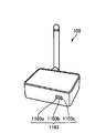
- FIG. 2 is an external view of a HEMS controller 100.
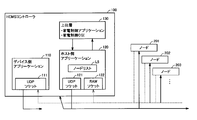
- FIG. 2 is a diagram for explaining an overall configuration of a HEMS controller 100. It is a figure for demonstrating the outline
- FIG. It is a figure for demonstrating the content which the host side application 120 notifies to the upper layer. It is a flowchart for demonstrating the process of the host side application 120 after the host side application 120 receives a packet from a node.
- 2 is a functional block diagram for explaining a functional configuration of a HEMS controller 100.
- FIG. 2 is a block diagram of a HEMS controller 100.
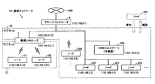
- FIG. It is a figure for demonstrating schematic structure of the communication network 1A. It is a flowchart for demonstrating the process of a passive node search.
- FIG. 1 is a diagram for explaining a schematic configuration of the communication network 1.
- the communication network 1 includes a broadband router 2 and a subnet 10.
- the broadband router 2 is connected to an external network 900.
- the subnet 10 includes a HEMS (Home Energy Management System) controller 100 and a plurality of nodes 201, 202, 203, 204,.
- a “node” is a communication device (IP compatible device) having an IP address.
- the nodes include personal computers, printers, NAS (network storage), tablet terminals, AV (Audio Visual) devices, white goods, and the like.
- Some of the plurality of nodes 201, 202, 203, 204,... Are “ECHONET ⁇ Lite nodes ”. In this embodiment, it is assumed that the nodes 201, 202, 203, and 204 are ECHONETONLite nodes.
- the HEMS controller 100 is connected to the broadband router 2 through a wired connection.
- a plurality of nodes 201, 202, 203, 204,... are also connected to the broadband router 2 in a wired or wireless manner so that they can communicate.
- the HEMS controller 100 functions as a repeater in the communication network 1. Specifically, the HEMS controller 100 controls the plurality of nodes 201, 202, 203, 204,... By communicating with the plurality of nodes 201, 202, 203, 204,.
- a new node 209 may join the subnet 10 or a node that joins the subnet 10 (hereinafter also referred to as “existing node”) may leave the subnet 10.
- existing node a node that joins the subnet 10
- the new node 209 joins the network, the new node 209 is treated as an existing node.
- the numbers in parentheses in FIG. 1 represent IP addresses.
- the broadband router 2 automatically assigns IP addresses to the HEMS controller 100 and the plurality of nodes 201, 202, 203, 204,... By the DHCP function.
- a device having a common part for example, “192.168.0” in “192.168.0.1” used as a network address in the IP address is a physical network (that is, , Subnet 10).
- the broadband router 2, the HEMS controller 100, and the nodes 201, 202, 203, 204,... Having the network address “192.168.0” constitute one physical network.
- FIG. 2 is a diagram showing the appearance of the HEMS controller 100.
- the HEMS controller 100 includes a light emitting element 1103 and an antenna 1107.
- the light emitting element 1103 includes three LEDs (Light (Emitting Diode) 1103a, 1103b, and 1103c for displaying the operation state of the HEMS controller 100 and the like.
- the LED 1103a is a light emitting element (power LED) for indicating whether the power of the HEMS controller 100 is on or off.
- the LED 1103b is a light emitting element for displaying a communication state with the nodes 201, 202, 203, 204,.
- the LED 1103 c is a light emitting element for displaying a communication state with the broadband router 2.
- FIG. 3 is a diagram for explaining the overall configuration of the HEMS controller 100.
- the HEMS controller 100 includes a device-side application 110, a host-side application 120, and an upper layer 130.
- the device-side application 110 includes a UDP (User Datagram Protocol) socket 111.
- the UDP socket 111 is common for transmission and reception, and is bound by the port 3610.
- the host-side application 120 includes a UDP socket 121 for transmission and a RAW socket 122 for reception.
- the host-side application 120 stores a node list L5.
- the device-side application 110 receives requests from the nodes 201, 202, 203, 204,..., And transmits a response or notification to the request.
- EOJ represents an ECHONET object (see 3.2.4 of Non-Patent Document 1 described above). Specifically, EOJ models information and access procedures to be disclosed to the network among information held by a communication IF (high-speed communication interface 1104 in FIG. 9) that performs ECHONET Lite communication.
- information and instances possessed by each node are defined as properties.
- an operation method (setting and reference) for nodes and instances is defined as a service.
- the EOJ is broadly classified into two types: an equipment object and a profile object (FIG. 5B).
- the host-side application 120 searches for the ECHONET Lite node and maintains the node list L5 in the latest state.
- the host side application 120 manages one or more instances on each node.
- the host-side application 120 acquires and stores the important property state of each instance at an appropriate timing. Therefore, the host-side application 120 transmits a request to the node by itself.
- the host-side application 120 receives a notification or a response to the request from the node.
- the host-side application 120 further provides an API (Application Programming Interface) to the upper layer 130 (home appliance control application or the like).
- the host-side application 120 receives an instruction from the upper layer 130 and returns the latest node list L5 and instance list (not shown) to the upper layer 130.
- the host-side application 120 receives an instruction from the upper layer 130 and transmits a request to the node. Further, the host-side application 120 receives a notification or a response to the request from the node and returns it to the upper layer 130.
- the upper layer 130 includes a home appliance control application, a home appliance control CGI (Common Gateway Interface), and a home appliance management information acquisition CGI (not shown). These are independent of each other. Each communicates with the host-side application independently.
- a home appliance control application a home appliance control CGI (Common Gateway Interface)
- a home appliance management information acquisition CGI not shown
- Each of the device-side application 110 and the host-side application 120 sets the transmission destination UDP port number to 3610 when transmitting a packet.
- the source UDP port number may be arbitrary.
- Each of the device-side application 110 and the host-side application 120 processes the destination UDP port number 3610 when receiving a packet.
- the host-side application 120 opens the UDP socket 121 for transmission. As described above, the host-side application 120 arbitrarily sets the transmission source port number of the UDP socket 121.
- the host-side application 120 opens the RAW socket 122 for reception.
- the reason why the RAW socket 122 is opened is that the source MAC address is obtained at the same time when the packet is received.
- the RAW socket 122 receives all data that can be received by the network interface “eth0”.
- the host-side application 120 uses data having UDP / IP and the destination UDP port number “3610” among all the received data.
- the HEMS controller 100 has a unique MAC address for each of the plurality of nodes 201, 202, 203, 204,... And an IP assigned to each of the plurality of nodes 201, 202, 203, 204,. It has a node list L5 associated with addresses.
- the HEMS controller 100 ensures the uniqueness of the node using the node list L5. That is, the HEMS controller 100 uses the MAC address and the IP address as the identifier of the ECHONET Lite device uniquely identified in the subnet 10.
- the HEMS controller 100 can identify an instance on a node with an EOJ code (3 bytes), and therefore, by combining these, the instance is uniquely identified with a MAC address (6 bytes) and an EOJ code (3 bytes). it can.
- FIG. 4 is a diagram for explaining the outline of the node list L5.
- a MAC address and an IP address are stored in association with each node.
- the node list L5 includes a plurality of pieces of node information D5 specified by identification numbers (No. 1, 2, 3,).
- the MAC address of the node 201 is the first “08: 00: 1F: 52: 2E: 57”.
- the MAC addresses of the nodes 202 and 203 are “08: 00: 1F: 48: 53: 4C” and “08: 00: 1F: 2D: 92: 6A”, respectively.
- the MAC address is unique (invariant), while the IP address assigned to the node changes according to the DHCP function of the broadband router 2.
- the host-side application 120 When the host-side application 120 receives a packet from a node based on a process of spontaneously searching for the node, the MAC address is included in the packet, so that the node can be found by referring to the node list L5. It can be determined whether or not it is a node. When the host-side application 120 determines that the packet is from an existing node, the IP address included in the packet is the IP address associated with the MAC address included in the packet in the node list L5. Determine whether they match. If the host-side application 120 determines that the IP addresses do not match, the host-side application 120 updates the IP address associated with the MAC address included in the packet in the node list L5 with the IP address included in the packet. .
- the host-side application 120 sends a packet including the MAC address “08: 00: 1F: 48: 53: 4C” and the IP address “192.168.0.7” to the node 202 (see FIG. 1) by spontaneous node search processing. ), It is determined that the IP addresses do not match. Specifically, the host-side application 120 can detect that the IP address has changed from “192.168.0.4” to “192.168.0.7”. In this case, the host-side application 120 updates the IP address associated with the MAC address “08: 00: 1F: 48: 53: 4C” with “192.168.0.7” in the node list L5 ( Overwrite.
- the host-side application 120 receives a packet including the MAC address of “08: 00: 1F: 48: 53: 4C” and the IP address of “192.168.0.5” from the node 202 by spontaneous node search processing . It is determined that the IP addresses do not match. If it is determined that they do not match, the host-side application 120 uses the IP address “192.168.0.4” associated with the MAC address “08: 00: 1F: 48: 53: 4C” in the node list L5. Update (overwrite) with “192.168.0.5”.
- the IP address “192.168.0.5” is not only the MAC address “08: 00: 1F: 48: 53: 4C” of the node 202 in the updated node list L5 (not shown).
- the MAC address “08: 00: 1F: 2D: 92: 6A” of 203 is also associated. That is, IP address duplication occurs in the node list L5.
- the host-side application 120 can determine that the node 203 has left the subnet 10. Therefore, the host-side application 120 deletes the node information D5 including the MAC address “08: 00: 1F: 2D: 92: 6A” of the node 203 from the node list L5.
- new node hereinafter also referred to as “new node” joins the subnet 10
- the host-side application 120 creates node information D5 of the node in the node list L5. To do. This will be described in detail as follows.
- the host-side application 120 When the host-side application 120 receives a packet from a node based on a process of spontaneously searching for a node, the MAC address is included in the packet, so that the node is newly created by referring to the node list L5. It can be determined whether or not it is a node. When the host-side application 120 determines that the packet is from the new node, the host-side application 120 determines whether or not the same IP address as the IP address received from the new node exists in the node list L5.
- the node-side application 120 When the host-side application 120 determines that the same IP address as the IP address received from the new node does not exist in the node list L5, the node-side application 120 adds the node information D5 related to the new node to the node list L5. On the other hand, if the host-side application 120 determines that the same IP address as the IP address received from the new node exists in the node list L5, the node-side application 120 adds the node information D5 related to the new node to the node list L5. The node information D5 including the same IP address is deleted from L5.
- the host-side application 120 receives a packet including the MAC address of “08: 00: 1F: 12: 34: 56” and the IP address of “192.168.0.5” by a spontaneous node search process (for example, the node 209 ( 1))), it is determined that the searched node is a new node because the same MAC address does not exist in the node list L5.
- a spontaneous node search process for example, the node 209 ( 1)
- IP address “192.168.0.5” is associated with the MAC address “08: 00: 1F: 2D: 92: 6A” of the node 203 in the updated node list L5. That is, IP address duplication occurs in the node list L5.
- the host-side application 120 can determine that the node 203 has left the subnet 10. Therefore, the host-side application 120 deletes the node information D5 including the MAC address “08: 00: 1F: 2D: 92: 6A” of the node 203 from the node list L5.
- the host-side application may receive packets from a node that conforms to ECHONETONLite beyond the broadband router 2. For example, when a spontaneous node search is not performed, such a packet may be received. In such a case, the broadband router 2 rewrites the MAC address in the packet with the MAC address of the router.
- node management using the node list L5 shown in FIG. 4 is an effective method in a range not exceeding the broadband router 2 (range of the subnet 10). For this reason, in order to perform node management appropriately, the host-side application 120 determines whether the packet is transmitted via the broadband router 2 when receiving the packet. If the host-side application 120 determines that the packet is via the broadband router 2, the node list L5 is not updated. Note that the host-side application 120 uses TTL (Time-to-Live) that indicates the valid period of the packet in order to determine whether the packet is transmitted via the broadband router 2. Details of the determination method will be described later.
- TTL Time-to-Live
- the host-side application 120 creates a node list L5 by searching for nodes (ECHONET Lite nodes) in the same subnet as the HEMS controller 100. Further, the host-side application 120 keeps the node list L5 in the latest state by periodically searching for nodes and by notification from the nodes. In addition, the host-side application 120 checks what instances exist on each node, and creates an instance list for each node. The host-side application 120 keeps the instance list up-to-date.
- the host-side application 120 issues a notification to the upper layer 130 (such as a home appliance control application) if there is a change in the node list L5, the state of the instance, or the monitoring property.
- the node list L5 held by the host-side application 120 and the state of the instance are returned.
- the host-side application 120 transmits an ECHONET Lite message to a specified node (more precisely, an instance of the node) according to an instruction from the upper layer 130.
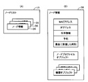
- FIG. 5 is a diagram for explaining the details of the node list L5 stored in the host-side application 120.
- FIG. 5A is a diagram showing a schematic configuration of the node list.
- FIG. 5B is a diagram for explaining node information included in the node list.
- the node list L5 includes a plurality of pieces of node information.
- each of the plurality of node information includes a MAC address, an IP address, survival information, a reservation, the time when the packet was last received, one node object, and one It is comprised including the above apparatus objects.
- Equipment object may be a logical model of information stored in equipment or white goods such as sensors, air conditioners, refrigerators, and / or control items that can be operated remotely.
- the interface format for remote control is unified.
- information and instances possessed by each node are defined as properties.
- an operation method (setting and reference) for nodes and instances is defined as a service.
- Node profile object is a model of profile information, control items, and setting items as an ECHONET Lite node, such as the operating state of a node (ECHONET Lite node), manufacturer information, and device object list.
- the HEMS controller 100 also functions as an ECHONETE Lite node in the communication network 1.
- the host-side application 120 does not perform node management for its own ECHONET Lite node. That is, the host-side application 120 manages nodes (nodes 201, 202, 203, 204, etc.) that are nodes other than the HEMS controller 100 and that constitute the subnet 10. This is because, when the RAW socket 122 is opened, the node transmitted from the host-side application 120 cannot be received.
- the host-side application 120 manages only nodes on the same subnet (that is, subnet 10) among the ECHONET Lite nodes.
- the host-side application 120 intentionally excludes the node located beyond the router (in this embodiment, the broadband router 2) even if the packet can be transmitted / received to / from the node. Designed to do.
- the host-side application 120 creates a node list by searching for a node (ECHONET Lite node) existing in the subnet 10. Find out what instances are on each node.
- the host-side application 120 creates an instance list for each node.
- the host-side application 120 changes the node list L5, the host-side application 120 notifies the upper layer 130 of the changed content.
- FIG. 6 is a diagram for explaining the contents notified from the host-side application 120 to the upper layer 130.
- the host-side application 120 finds a new node, it notifies the upper layer 130 of a notification “node-added”.
- the host-side application 120 notifies the upper layer 130 of a notification “node-removed” when an existing node is deleted.
- the host-side application 120 detects a node with a different MAC address at the same IP address as the existing node, (ii) the existing node is in a missing state and the last packet is received from the node. It is determined that the existing node has been deleted when 3 hours or more have elapsed.
- the host-side application 120 notifies the upper layer 130 of a notification “address-changed” when the IP address of the existing node changes.
- spontaneous node search by the host-side application 120 Next, spontaneous node search by the host-side application 120 will be described.
- the host-side application 120 performs a spontaneous node search immediately after startup.
- the host-side application performs a spontaneous node search every predetermined time (for example, 5 minutes) after startup.
- the search frame is as described in Chapter 4.3 (Guidelines for node detection / discovery procedure) in Part 5 of the ECHONET Lite standard. Specifically, the details of the search frame are as follows.
- the host-side application 120 targets only packets received by unicast.
- the host-side application 120 does not receive a packet or receives a packet from one or more nodes.
- the host-side application 120 can accept a packet only for 5 seconds after the simultaneous broadcast. Alternatively, the host-side application 120 may be allowed to accept until a search frame is transmitted next time without providing a timeout period.
- the host side application 120 confirms the received packet. Specifically, whether the values of “SEOJ”, “DEOJ”, and “TID (16 bits)” match “SEOJ”, “DEOJ”, and “TID (16 bits)” in the transmitted packet. Confirm whether or not. The host-side application 120 may ignore the received packet that does not match.
- FIG. 7 is a flowchart for explaining processing of the host-side application 120 after the host-side application 120 receives a packet from the node.
- host-side application 120 confirms the MAC address and IP address of the received packet.
- the confirmed MAC address is “XX...”
- the confirmed IP address is “YY.
- XX ... is one fixed address such as 08: 00: 1F: 2D: 92: 6A
- YY ... is one fixed address such as 192.168.0.1. That is, “...” represents an ellipsis.
- step S4 the host-side application 120 determines whether or not MAC addresses XX... Exist in the node list L5 (see FIG. 4). When it is determined that the MAC address exists (YES in step S4), the host-side application 120 determines whether or not the IP address of the node having the MAC address XX... Has changed in the node list L5 in step S6. To do.
- step S8 the host-side application 120 uses the IP address in the node list L5 to set the MAC address of XX. Update the IP address of the existing node with In step S10, the host-side application 120 sends a notification (specifically, address-changed) indicating that the IP address of the existing node having the MAC address of XX... Has changed to the upper layer 130. Note that the host-side application 120 proceeds to step S14 after step S10. If it is determined that the IP address has not changed (NO in step S6), the host-side application 120 ends the series of processing.
- a notification specifically, address-changed
- the host-side application 120 If it is determined that there is no MAC address of XX ... (NO in step S4), the host-side application 120 has the MAC address of XX ... in the node list L5 in step S12, and the IP address of YY ... Add node information (including IP address, MAC address, etc.) of the new node. That is, the host-side application 120 newly registers a node and sends a notification “node-added” to the upper layer 130.
- step S14 the host-side application 120 determines whether or not the IP address YY... Exists in the node list L5. If it is determined that the host-side application 120 exists (YES in step S14), in step S16, the node information of the existing nodes having IP addresses of YY... And having a MAC address other than XX. To do. In step S18, the host-side application 120 notifies the upper layer 130 of a notification (specifically, node-removed) indicating that an existing node having an IP address of YY... And having a MAC address other than XX. send. When it is determined that the YY... IP address does not exist (NO in step S14), the host-side application 120 ends the series of processes.
- a notification specifically, node-removed
- the host-side application 120 may receive an instance list notification from a node (another ECHONET Lite node).
- the instance list notification is notified when the power is turned on.
- the instance list notification has the same contents as the self-node instance list S.
- the host-side application 120 When the host-side application 120 receives an instance list notification from a known node, the host-side application 120 performs the same process as the above “spontaneous node search”. On the other hand, when receiving an instance list notification from an unknown node, the host-side application performs a process different from that when receiving an instance list notification from a known node.
- node search that is, passive node search
- the host-side application 120 When the host-side application 120 receives an instance list notification from an unknown node, the host-side application 120 does not register the unknown node in the node list L5 at the time of reception. For this reason, the host-side application 120 does not notify “node-added” to the upper layer 130 because it is not known whether the unknown node exists on the same subnet as the HEMS controller 100.
- the host-side application 120 transmits a predetermined packet (hereinafter also referred to as “packet P”) by unicast to the unknown node.
- packet P a predetermined packet
- the host-side application 120 tries to acquire its own node instance list S.
- a response to the packet P is sent by unicast.
- the host-side application 120 registers a new node in the node list L5 when the response is sent.
- the host-side application 120 issues a notification “node-added” to the upper layer 130.
- FIG. 11 is a flowchart for explaining passive node search processing.
- the passive node search process differs from the spontaneous node search shown in FIG. 7 in that step S102 and step S104 exist between step S4 and step S12. . Therefore, in the following, processing different from the processing in FIG. 7 will be described, and description of the same processing will not be repeated.
- step S104 the host-side application 120 determines whether or not there is a response to the packet P. If the host-side application 120 determines that there is a response (YES in step S104), the process proceeds to step S12. If the host-side application 120 determines that there is no response (NO in step S104), the host-side application 120 does not register the unknown node.
- FIG. 8 is a functional block diagram for explaining the functional configuration of the HEMS controller 100.
- the HEMS controller 100 includes a communication unit 140, a node control unit 150, and a storage unit 160.
- Node control unit 150 includes a determination unit 151, an update unit 152, a search unit 153, and a determination unit 154.
- the host-side application 120 includes a communication unit 140, a node control unit 150, and a storage unit 160.
- functional blocks that perform communication between the device-side application and the node are not shown for convenience of explanation. The function of each block will be described below.
- the HEMS controller 100 is included in the subnet 10 configured by the broadband router 2.
- the communication unit 140 of the HEMS controller 100 communicates with a plurality of nodes 201, 202, 203, 204,... Each having a MAC address and an IP address.
- the communication unit 140 communicates with the broadband router 2.
- the node control unit 150 controls a plurality of nodes 201, 202, 203, 204,... Participating in the subnet 10 among the plurality of nodes.
- the storage unit 160 stores a node list L5 (first data). In the node list L5, the MAC address and IP address of the first node are associated with each other.
- the IP address of the first node is assigned by the broadband router 2.
- the determination unit 154 of the node control unit 150 causes the packet S (second data) to pass through the broadband router 2. It is determined whether or not it has been sent.
- the determination unit 151 of the node control unit 150 includes the IP address included in the packet S in the packet S in the node list L5. It is determined whether or not it matches the IP address associated with the same MAC address as the existing MAC address.
- the update unit 152 of the node control unit 150 determines that the IP address associated with the same MAC address as the MAC address included in the second data in the node list L5 based on the determination that the IP addresses do not match. The address is updated with the IP address included in the packet S.
- the uniqueness of the node can be ensured without using special identification information such as an Echonet address. Since the HEMS controller 100 manages a pair of a MAC address and an IP address, the same node can be tracked even when the IP address of the node is changed by the router. In other words, the host-side application 120 notices that the IP address has changed. As a result, accurate node management can be performed.
- the determination unit 154 When the determination unit 154 receives the packet S, the determination unit 154 transmits the predetermined packet T (third data) to the node that is the transmission source of the second data, so that the second data is It is determined whether or not the data has been transmitted over the broadband router 2.
- the packet T includes a value indicating the validity period of the packet T. Specifically, in the packet T, TTL is set to “1”. According to said structure, it can prevent that the node which transmitted packet S (in this case instance list notification) exceeding a router is registered into the node list L5.
- the search unit 153 of the node control unit 150 searches for a node spontaneously at a predetermined time interval.
- the determination unit 154 receives the packet S without being based on a spontaneous node search
- the determination unit 154 transmits the packet T to the node that has transmitted the packet S (in this case, the instance list notification).
- the HEMS controller 100 does not need to transmit the packet T when receiving the packet S based on the spontaneous node search.
- the updating unit 152 deletes the IP address other than the updated IP address from the node list L5 among the duplicated IP addresses. . According to the above configuration, an unnecessary IP address can be deleted from the node list L5.
- the determination unit 154 determines whether the same IP address as the IP address included in the packet S exists in the node list L5. .
- the updating unit 152 deletes the same IP address from the node list L5.
- the updating unit 152 When deleting the IP address from the node list L5, the updating unit 152 further deletes the MAC address associated with the IP address to be deleted from the node list L5. According to the above configuration, unnecessary MAC addresses can be erased from the node list L5.
- the update unit 152 also obtains an IP address and a MAC address from the node list L5 even when the existing node is in a missing state and more than three hours have elapsed since the last packet S was received from the node. to erase. Specifically, the update unit 152 deletes the node information D5 (FIG. 5).
- FIG. 9 is a block diagram of the HEMS controller 100.
- the HEMS controller 100 includes a CPU 1101, a light emitting element 1103, a high-speed communication interface 1104, a power source 1105, a push button 1108, a slide switch 1109, and a reset switch (not shown).
- the high-speed communication interface 1104 is an interface for performing communication with the broadband router 2 using Ethernet (registered trademark).
- the power source 1105 supplies power to the CPU 1101 and the wireless RF communication controller 1106.
- the CPU 1101 is connected to a light emitting element 1103, a high-speed communication interface 1104, a power source 1105, a push button 1108, and a slide switch 1109.
- the CPU 1101 controls the overall operation of the HEMS controller 100.
- the CPU 1101 receives input from the push button 1108 and the slide switch 1109. In addition, the CPU 1101 issues an output instruction to the light emitting element 1103.
- FIG. 10 is a diagram for explaining a schematic configuration of the communication network 1A.
- a communication network 1A includes a broadband router 2, a HEMS controller 100, a plurality of nodes 201, 202, 203, 204,..., A wireless local area network (LAN) router 3, a node 31, 32.
- LAN local area network
- the wireless LAN router 3 is communicably connected to the broadband router 2.
- the wireless LAN router 3 is given an IP address by a broadband router.
- the wireless LAN 3 communicates with the nodes 31 and 32 wirelessly.
- the communication network 1A includes a subnet 10A and a subnet 30.
- the subnet 10A includes the HEMS controller 100, a plurality of nodes 201, 202, 203, 204,... And the wireless LAN router 3.
- the subnet 30 includes a wireless LAN 3 and nodes 31 and 32. In the communication network 1A, each process described in the subnet 10 can be executed in the subnet 10A.
- the third data includes a value indicating the valid period of the third data.
- the controller communicates with nodes participating in the subnet based on the Echonet Light standard.
- the second data received without being based on the spontaneous node search is an instance list notification.
- the updating means uses the variable identification information other than the updated variable identification information among the duplicated variable identification information as the first data. Delete from the data.
- the second determination means includes the variable identification information that is the same as the variable identification information included in the second data in the first data. Determine if it exists.
- the update means deletes the same variable identification information from the first data when the variable identification information identical to the variable identification information included in the second data exists in the first data.
- the updating means further erases the unique identification information associated with the variable identification information erased from the first data.
- the unique identification information is a media access control address.
- the variable identification information is an Internet protocol address.
- the program controls the controllers included in the subnet configured by the router.
- the controller can communicate with a plurality of nodes each having unique identification information and variable identification information.
- the program stores first data in which a step of controlling a node participating in a subnet among a plurality of nodes is associated with unique identification information and variable identification information of a node participating in the subnet. The step is executed by the processor of the controller.
- the variable identification information of the nodes participating in the subnet is assigned by the router.
- the program when the second data including the unique identification information and the variable identification information is received, determines whether the second data has been transmitted across the router; When the second data is not transmitted across the router, the variable identification information included in the second data is a unique identification included in the second data in the first data.
- variable identification information In the first data, based on determining whether or not the variable identification information matches the variable identification information associated with the same unique identification information as the information and the variable identification information does not match Updating variable identification information associated with the same unique identification information as the unique identification information included in the second data with the variable identification information included in the second data, To the processor To be executed in La.
Landscapes
- Engineering & Computer Science (AREA)
- Automation & Control Theory (AREA)
- Computer Networks & Wireless Communication (AREA)
- Signal Processing (AREA)
- Small-Scale Networks (AREA)
Abstract
ルータによって構成されたサブネットに含まれるコントローラであって、制御手段と、前記サブネットに参加しているノードの固有の識別情報と可変の識別情報とを関連付けた第1のデータを記憶する記憶手段とを備え、前記制御手段は、前記固有の識別情報と前記可変の識別情報とを含む第2のデータが受信された場合、前記第2のデータが、前記ルータを越えて送信されてきたものか否かを判断し、前記第2のデータが前記ルータを越えて送信されてきたものではない場合に、前記第2のデータに含まれている可変の識別情報が、前記第1のデータにおいて同一の固有の識別情報に関連付けられている可変の識別情報と一致するか否かを判断し、一致しない場合には、前記第1のデータにおいて前記第2のデータに含まれている固有の識別情報と同一の固有の識別情報に関連付けられている可変の識別情報を、前記第2のデータに含まれている可変の識別情報で更新する。
Description
本発明は、コントローラ、サブネット、および情報処理方法に関する。
従来、家庭内の機器を制御するためのECHONET(登録商標)などの通信プロトコルが知られている。ECHONETでは、NodeIDとして付与されるアドレス(以下、「エコーネットアドレス」と称する)を用いて、通信機器が識別される。エコーネットアドレスは、ルータによって付与される。エコーネットアドレスは1バイトであるため、1つのサブネットにおいては256台までの通信機器しか登録できない。256台以上の通信機器をネットワークに接続するためには、当該ネットワークを複数のサブネットに分割する必要がある。
特許文献1には、サーバに接続されるとともに、ECHONETに従った通信を行なう通信端末が開示されている。特許文献1は、1つのサブネットに、多数のノードを接続することを課題としている。この課題を達成するため、上記通信端末の処理部は、パケットを受信すると、受信したパケットの送信元エコーネットアドレスが、通信端末に付与された自己のエコーネットアドレスと同一の場合、受信したパケットのIPアドレスおよびハードウエアアドレスを対応付けて、重複アドレステーブル記憶部に記憶する。処理部は、通信端末がサーバと通信する際、重複アドレステーブル記憶部にデータが格納されていない場合、自己のエコーネットアドレスを用いてサーバと通信する。処理部は、重複アドレステーブル記憶部にデータが格納されている場合、重複アドレステーブル記憶部に記憶されたIPアドレスを用いてパケットを送信し、応答がなかった場合、自己のエコーネットアドレスを用いてサーバと通信し、応答があった場合、新たに自己のエコーネットアドレスを取得して、新たに取得したエコーネットアドレスを用いてサーバと通信する。
また、従来、非特許文献1に示すように、ECHONETの通信ミドルウェア部分を作り直したECHONET Lite(登録商標)が知られている。ECHONET Liteでは、ECHONETにおいて規格対象になっていた物理層およびMAC層等を規格の対象外としている。
また、非特許文献2の「2.2 ECHONET Lite ネットワーク構成」には、ECHONET Liteのネットワーク構成モデルが図示(図2-3)されているとともに、「サブネット内では、伝送メディアにおけるレイヤ2の通信を実現するアドレス(以下、本規格においては「MACアドレス」と呼ぶ)、もしくはIPアドレスを、サブネット内でユニークに識別されるECHONET Lite機器の識別子として用います。」との記載がなされている。
ECHONET Lite SPECIFICATION 第2部 ECHONET Lite 通信ミドルウェア仕様,Date:May 31,2013, Version 1.10,ECHONET CONSORTIUM
ECHONET Lite SPECIFICATION 第1部 ECHONET Liteの概要,Date:May 31,2013, Version 1.10,ECHONET CONSORTIUM
ECHONETに準拠した特許文献1の通信システムは、エコーネットアドレスと重複アドレステーブル(IPアドレスおよびハードウエアアドレス)とによって、ノードの一意性を担保している。
しかしながら、ECHONET Liteは、エコーネットアドレスに関する仕様を有していない。したがって、ECHONET Liteに準拠したネットワークは、ノードの一意性を担保するために、特許文献1に示された手法を用いることはできない。
また、ルータは、一般的にDHCP(Dynamic Host Configuration Protocol)機能によりIPアドレスを自動的に割り当てる。したがって、ノードのIPアドレスは変更されうる可能性がある。ルータの設定により固定IPアドレスにすることもできるけれども、そのように設定されている保証はない。IPアドレスは変更されうる可能性があるため、この点からも、少なくともIPアドレスだけを用いてノードの一意性を担保することはできない。
さらに、ECHONET Lite規格には、ノードを一意に決定する必須プロパティがあるとは言えない。例えば、Version 1.10 以降のときは識別番号(EPC=0x83)が使えるけども、Version 1.01 以前のときは「1バイト目0x00のとき未設定可能」というのが許されており、実質使えない。異なるバージョンが混在したときに汎用的に使えない。この点からも、ECHONET Liteに準拠した必須プロパティの範囲内では、ノードの一意性を担保することはできない。
また、MACアドレスをECHONET Lite機器の識別子として使用した場合であっても、以下の問題が生じる。すなわちコントローラは、サブネットを構成するルータを越えて、ECHONET Liteに準拠したノードからパケットを受信することがありえる。このような場合には、ルータは、パケット内の送信元MACアドレスを当該ルータのMACアドレスに書き換えてしまう。サブネットを越えて存在するノード(つまり、ルータを越えて通信可能なノード)のMACアドレスを調べる一般的な方法はないため、ルータを越えて受信したパケットの送信元MACアドレスは分からない。このため、コントローラは、サブネットを越えて存在するノードを、正しくないMACアドレスでもってサブネット内のECHONET Liteノードとして登録してしまう虞がある。
その結果、サブネットにおいては、ノードの一意性が担保できなくなる。ノードの一意性を担保できるというのは、IPアドレスの変化等に影響されずに、コントローラがノードを一意に識別することである。
本発明は、上記の問題点に鑑みなされたものであって、その目的は、エコーネットアドレス等の特殊な識別情報を用いることなく、ノードの一意性を担保することが可能なコントローラ、サブネット、および当該コントローラにおける情報処理方法を提供することにある。
本発明のある局面に従うと、コントローラは、ルータによって構成されたサブネットに含まれる。コントローラは、各々が固有の識別情報と可変の識別情報とを有する複数のノードと通信するための通信手段と、複数のノードのうち、サブネットに参加しているノードを制御するための制御手段と、サブネットに参加しているノードの固有の識別情報と可変の識別情報とを関連付けた第1のデータを記憶する記憶手段とを備える。サブネットに参加しているノードの可変の識別情報は、ルータによって割り当てられる。制御手段は、固有の識別情報と可変の識別情報とを含む第2のデータが受信された場合、第2のデータが、ルータを越えて送信されてきたものか否かを判断する第1の判断手段と、第2のデータがルータを越えて送信されてきたものではない場合に、第2のデータに含まれている可変の識別情報が、第1のデータにおいて第2のデータに含まれている固有の識別情報と同一の固有の識別情報に関連付けられている可変の識別情報と一致するか否かを判断する第2の判断手段と、可変の識別情報が一致しないと判断されたことに基づき、第1のデータにおいて第2のデータに含まれている固有の識別情報と同一の固有の識別情報に関連付けられている可変の識別情報を、第2のデータに含まれている可変の識別情報で更新する更新手段とを含む。
好ましくは、第1の判断手段は、第2のデータを受信した場合、予め定められた第3のデータを第2のデータの送信元のノードに送信することによって、第2のデータがルータを越えて送信されてきたものか否かを判断する。
好ましくは、制御手段は、予め定められた時間間隔で自発的にノードを探索する探索手段をさらに備える。第1の判断手段は、自発的なノードの探索に基づくことなく第2のデータを受信した場合、第3のデータを第2のデータの送信元のノードに送信する。
本発明の他の局面に従うと、ルータによって構成されたサブネットは、コントローラとルータとを備える。コントローラは、各々が固有の識別情報と可変の識別情報とを有する複数のノードと通信するための通信手段と、複数のノードのうち、サブネットに参加しているノードを制御するための制御手段と、サブネットに参加しているノードの固有の識別情報と可変の識別情報とを関連付けた第1のデータを記憶する記憶手段とを備える。サブネットに参加しているノードの可変の識別情報は、ルータによって割り当てられる。制御手段は、固有の識別情報と可変の識別情報とを含む第2のデータが受信された場合、第2のデータが、ルータを越えて送信されてきたものか否かを判断する第1の判断手段と、第2のデータがルータを越えて送信されてきたものではない場合に、第2のデータに含まれている可変の識別情報が、第1のデータにおいて第2のデータに含まれている固有の識別情報と同一の固有の識別情報に関連付けられている可変の識別情報と一致するか否かを判断する第2の判断手段と、可変の識別情報が一致しないと判断されたことに基づき、第1のデータにおいて第2のデータに含まれている固有の識別情報と同一の固有の識別情報に関連付けられている可変の識別情報を、第2のデータに含まれている可変の識別情報で更新する更新手段とを有する。
本発明のさらに他の局面に従うと、情報処理方法は、ルータによって構成されたサブネットに含まれるコントローラにおいて実行される。コントローラは、各々が固有の識別情報と可変の識別情報とを有する複数のノードと通信する。情報処理方法は、複数のノードのうち、サブネットに参加しているノードを制御するステップと、サブネットに参加しているノードの固有の識別情報と可変の識別情報とを関連付けた第1のデータを記憶するステップとを備える。サブネットに参加しているノードの可変の識別情報は、ルータによって割り当てられる。情報処理方法は、固有の識別情報と可変の識別情報とを含む第2のデータが受信された場合、第2のデータが、ルータを越えて送信されてきたものか否かを判断するステップと、第2のデータがルータを越えて送信されてきたものではない場合に、第2のデータに含まれている可変の識別情報が、第1のデータにおいて第2のデータに含まれている固有の識別情報と同一の固有の識別情報に関連付けられている可変の識別情報と一致するか否かを判断するステップと、可変の識別情報が一致しないと判断されたことに基づき、第1のデータにおいて第2のデータに含まれている固有の識別情報と同一の固有の識別情報に関連付けられている可変の識別情報を、第2のデータに含まれている可変の識別情報で更新するステップとをさらに備える。
本発明によれば、サブネットにおいてノードの一意性を担保することが可能となる。
以下、図面を参照しつつ、本発明の実施の形態に係るネットワークについて説明する。また、以下の説明では、同一の部材には同一の参照符号を付してある。それらの名称および機能も同じである。したがって、それらについての詳細な説明は繰り返さない。
<A.通信ネットワーク1の概略構成>
図1は、通信ネットワーク1の概略構成を説明するための図である。図1を参照して、通信ネットワーク1は、ブロードバンドルータ2と、サブネット10とを備えている。ブロードバンドルータ2は、外部のネットワーク900と接続している。
図1は、通信ネットワーク1の概略構成を説明するための図である。図1を参照して、通信ネットワーク1は、ブロードバンドルータ2と、サブネット10とを備えている。ブロードバンドルータ2は、外部のネットワーク900と接続している。
サブネット10は、HEMS(Home Energy Management System)コントローラ100と、複数のノード201,202,203,204,…とを備える。「ノード」とは、IPアドレスを持つ通信機器(IP対応機器)である。一般的には、ノードは、パソコン、プリンタ、NAS(ネットワークストレージ)、タブレット端末、AV(Audio Visual)機器、白物家電などが挙げられる。複数のノード201,202,203,204,…のうちいくつかが、「ECHONET Liteノード」である。本実施の形態では、ノード201,202,203,204がECHONET Liteノードであるとする。
HEMSコントローラ100は、ブロードバンドルータ2に通信可能に有線で接続されている。複数のノード201,202,203,204,…も、ブロードバンドルータ2に通信可能に有線あるいは無線で接続されている。
HEMSコントローラ100は、通信ネットワーク1において中継器として機能する。具体的には、HEMSコントローラ100は、複数のノード201,202,203,204,…と通信することにより、複数のノード201,202,203,204,…を制御する。
本実施の形態では、新規ノード209がサブネット10に参加したり、サブネット10に参加しているノード(以下、「既存ノード」とも称する)がサブネット10から離脱することがある。なお、新規ノード209がネットワークに参加した場合には、新規ノード209は既存ノードとして扱われる。
ところで、図1における括弧内の数字(たとえば、192.168.0.1)は、IPアドレスを表している。ブロードバンドルータ2は、DHCP機能によって、HEMSコントローラ100と、複数のノード201,202,203,204,…とに対して、IPアドレスを自動的に付与する。
付与されたIPアドレスから分かるように、IPアドレスのうちのネットワークアドレスとして使用される部分(たとえば、“192.168.0.1”における“192.168.0”の部分)が共通する機器が物理的なネットワーク(つまり、サブネット10)を構成する。“192.168.0”のネットワークアドレスを有する、ブロードバンドルータ2と、HEMSコントローラ100と、ノード201,202,203,204,…とが、1つの物理的なネットワークを構成する。
図2は、HEMSコントローラ100の外観を表した図である。図2を参照して、HEMSコントローラ100は、発光素子1103と、アンテナ1107とを備える。発光素子1103は、HEMSコントローラ100の動作状態等を表示するための3つのLED(Light Emitting Diode)1103a,1103b,1103cにより構成される。
LED1103aは、HEMSコントローラ100の電源がオン・オフの状態を示すための発光素子(電源LED)である。LED1103bは、ノード201,202,203,204,…との通信状態を表示するための発光素子である。LED1103cは、ブロードバンドルータ2との通信状態を表示するための発光素子である。
以下では、主として、サブネット10に着目して説明を行なう。
<B.HEMSコントローラ100の全体構成>
図3は、HEMSコントローラ100の全体構成を説明するための図である。図3を参照して、HEMSコントローラ100は、デバイス側アプリケーション110と、ホスト側アプリケーション120と、上位層130とを備える。デバイス側アプリケーション110はUDP(User Datagram Protocol)ソケット111を備える。UDPソケット111は、送信用と受信用に共通で、ポート3610でバインドさせる。また、ホスト側アプリケーション120は、送信用のUDPソケット121と、受信用のRAWソケット122とを備える。また、ホスト側アプリケーション120は、ノードリストL5を記憶している。
<B.HEMSコントローラ100の全体構成>
図3は、HEMSコントローラ100の全体構成を説明するための図である。図3を参照して、HEMSコントローラ100は、デバイス側アプリケーション110と、ホスト側アプリケーション120と、上位層130とを備える。デバイス側アプリケーション110はUDP(User Datagram Protocol)ソケット111を備える。UDPソケット111は、送信用と受信用に共通で、ポート3610でバインドさせる。また、ホスト側アプリケーション120は、送信用のUDPソケット121と、受信用のRAWソケット122とを備える。また、ホスト側アプリケーション120は、ノードリストL5を記憶している。
デバイス側アプリケーション110は、HEMSコントローラ100自身が、ECHONET Liteにおけるコントローラ(EOJ=05.FF.01)として振る舞うためのアプリケーションである。デバイス側アプリケーション110は、ノード201,202,203,204,…からの要求を受信して、当該要求に対して応答または通知を送信する。
なお、“EOJ”は、ECHONETオブジェクトを表している(上述した非特許文献1の3.2.4参照)。具体的には、EOJは、ECHONET Liteの通信を行なう通信IF(図9における高速通信インターフェイス1104)が保持する情報のうち、ネットワークに対して公開する情報やアクセス手順をモデル化したものである。EOJには、各々のノードが持つ情報およびインスタンスがプロパティとして規定されている。また、EOJには、ノードおよびインスタンスに対する操作方法(設定、参照)がサービスとして規定されている。EOJは、詳細については後述するが、機器オブジェクト、プロファイルオブジェクトの2つに大きく分類される(図5(B))。
ホスト側アプリケーション120は、ECHONET Liteのノードを探索し、ノードリストL5を最新の状態に維持する。ホスト側アプリケーション120は、各ノード上の1つ以上のインスタンスを管理する。ホスト側アプリケーション120は、適当なタイミングで、各インスタンスの重要プロパティの状態を取得して保存する。そのために、ホスト側アプリケーション120は、自身が主体となって、ノードへ要求を送信する。また、ホスト側アプリケーション120は、通知または当該要求に対する応答を当該ノードから受信する。
ホスト側アプリケーション120は、さらに、上位層130(家電制御アプリケーション等)にAPI(Application Programming Interface)を提供する。ホスト側アプリケーション120は、上位層130からの指示を受けて、最新のノードリストL5やインスタンスリスト(図示せず)を上位層130に返す。また、ホスト側アプリケーション120は、上位層130からの指示を受けて、ノードへ要求を送信する。また、ホスト側アプリケーション120は、通知または当該要求に対する応答を当該ノードから受信し、上位層130へ返す。
なお、上位層130としては、家電制御アプリケーション、家電制御CGI(Common Gateway Interface)、家電管理情報取得CGI(図示せず)がある。これらは互いに独立である。各々が独立して、ホスト側アプリと通信する。
デバイス側アプリケーション110およびホスト側アプリケーション120の各々は、パケットを送信するときは送信先UDPポート番号を3610にする。送信元UDPポート番号は任意で良い。デバイス側アプリケーション110およびホスト側アプリケーション120の各々は、パケットを受信するときは、送信先UDPポート番号3610を処理する。
ホスト側アプリケーション120は、送信用にUDPソケット121を開く。なお、上述したように、ホスト側アプリケーション120は、UDPソケット121の送信元ポート番号を任意に設定する。
ホスト側アプリケーション120は、受信用にRAWソケット122を開く。RAWソケット122を開くのは、パケットを受信すると同時に送信元MACアドレスも得るためである。RAWソケット122は、ネットワークインターフェイス“eth0”で受信できるデータをすべて受信する。ホスト側アプリケーション120は、受信した全てのデータの中から、UDP/IPかつ宛先UDPポート番号が“3610”であるデータを利用する。
なお、別途、ARPを送信してMACアドレスを得るという手法もあるが、当該方法は、余分なトラフィックが発生するため、上記のように、RAWソケットを利用することが好ましい。
<C.HEMSコントローラ100の処理の概要>
HEMSコントローラ100は、複数のノード201,202,203,204,…の各々に固有のMACアドレスと、ブロードバンドルータ2によって複数のノード201,202,203,204,…の各々に対して割り当てられるIPアドレスとを関連付けたノードリストL5を有している。HEMSコントローラ100は、ノードリストL5を用いて、ノードの一意性を担保する。つまり、HEMSコントローラ100は、MACアドレスとIPアドレスとを、サブネット10内でユニークに識別されるECHONET Lite機器の識別子として用いる。
HEMSコントローラ100は、複数のノード201,202,203,204,…の各々に固有のMACアドレスと、ブロードバンドルータ2によって複数のノード201,202,203,204,…の各々に対して割り当てられるIPアドレスとを関連付けたノードリストL5を有している。HEMSコントローラ100は、ノードリストL5を用いて、ノードの一意性を担保する。つまり、HEMSコントローラ100は、MACアドレスとIPアドレスとを、サブネット10内でユニークに識別されるECHONET Lite機器の識別子として用いる。
なお、HEMSコントローラ100は、ノード上にあるインスタンスはEOJコード(3バイト)で識別できるため、これらを組み合わせて、MACアドレス(6バイト)とEOJコード(3バイト)とで、インスタンスをユニークに識別できる。
図4は、ノードリストL5の概要を説明するための図である。図4を参照して、ノードリストL5においては、MACアドレスとIPアドレスとがノード毎に関連付けて記憶されている。ノードリストL5は、識別番号(No.1,2,3…)で特定される複数のノード情報D5で構成される。
ノードリストL5と図1に示した状態と対比すれば、ノード201のMACアドレスは、1番目の“08:00:1F:52:2E:57”である。また、ノード202およびノード203の各々のMACアドレスは、“08:00:1F:48:53:4C”、“08:00:1F:2D:92:6A”である。上述したように、MACアドレスは固有(不変)であるのに対し、ノードに割り当てられたIPアドレスは、ブロードバンドルータ2のDHCP機能により変化する。
以下では、サブネット10にノードが参加したり、あるいはサブネット10からノードが離脱した場合における、HEMSコントローラ100における代表的な処理を説明する。
(c1.ルータを越えていないパケットを受信した場合の処理)
以下では、説明の便宜上、HEMSコントローラ100が受信したパケットがブロードバンドルータ2を越えていないもの(つまり、サブネット10内のノードから送られてきたもの)である場合について、3つの処理を説明する。
以下では、説明の便宜上、HEMSコントローラ100が受信したパケットがブロードバンドルータ2を越えていないもの(つまり、サブネット10内のノードから送られてきたもの)である場合について、3つの処理を説明する。
(1)ノードリストL5におけるIPアドレスの更新
ブロードバンドルータ2のDHCP機能によって、既存ノードのIPアドレスが変化した場合には、ホスト側アプリケーション120は、ノードリストL5において当該既存ノードのMACアドレスに関連付けられているIPアドレスを、変化後のIPアドレスで更新する。つまり、ホスト側アプリケーション120は、変化後のIPアドレスに書き換える。詳しく説明すると以下のとおりである。
ブロードバンドルータ2のDHCP機能によって、既存ノードのIPアドレスが変化した場合には、ホスト側アプリケーション120は、ノードリストL5において当該既存ノードのMACアドレスに関連付けられているIPアドレスを、変化後のIPアドレスで更新する。つまり、ホスト側アプリケーション120は、変化後のIPアドレスに書き換える。詳しく説明すると以下のとおりである。
ホスト側アプリケーション120は、ノードを自発的に探索する処理に基づいてノードからパケットを受信した場合、当該パケットにはMACアドレスが含まれているため、ノードリストL5を参照することにより、ノードが既存ノードであるか否かを判断できる。ホスト側アプリケーション120は、既存ノードからのパケットであると判断した場合、当該パケットに含まれているIPアドレスが、ノードリストL5において当該パケットに含まれているMACアドレスに関連付けられているIPアドレスと一致しているか否かを判断する。ホスト側アプリケーション120は、IPアドレスが一致しないと判断した場合、ノードリストL5において上記パケットに含まれているMACアドレスに関連付けられているIPアドレスを、当該パケットに含まれていたIPアドレスで更新する。
具体例を挙げて説明すれば、以下のとおりである。ホスト側アプリケーション120は、“08:00:1F:48:53:4C”のMACアドレスと“192.168.0.7”のIPアドレスとを含むパケットを、自発的なノード探索処理によってノード202(図1参照)から受信した場合、IPアドレスが一致していないと判断する。具体的には、ホスト側アプリケーション120は、IPアドレスが“192.168.0.4”から“192.168.0.7”に変化したことを検知できる。この場合、ホスト側アプリケーション120は、ノードリストL5において、MACアドレス“08:00:1F:48:53:4C”に関連付けられたIPアドレスを“192.168.0.4”を“192.168.0.7”で更新(上書き)する。
(2)ノード情報D5の消去
上記のように既存ノードのIPアドレスが変化した場合において、IPアドレスの更新によって、ノードリストL5においてIPアドレスが重複することが起こり得る。この場合、ホスト側アプリケーションは、当該重複しているIPアドレスのうち当該更新されたIPアドレス以外のIPアドレスを含むノード情報D5を、ノードリストL5から消去する。
上記のように既存ノードのIPアドレスが変化した場合において、IPアドレスの更新によって、ノードリストL5においてIPアドレスが重複することが起こり得る。この場合、ホスト側アプリケーションは、当該重複しているIPアドレスのうち当該更新されたIPアドレス以外のIPアドレスを含むノード情報D5を、ノードリストL5から消去する。
具体例を挙げて説明すれば、以下のとおりである。ホスト側アプリケーション120は、“08:00:1F:48:53:4C”のMACアドレスと“192.168.0.5”のIPアドレスとを含むパケットを、自発的なノード探索処理によってノード202から受信した場合、IPアドレスが一致していないと判断する。なお、一致していないと判断した場合には、ホスト側アプリケーション120は、ノードリストL5において、MACアドレス“08:00:1F:48:53:4C”に関連付けられたIPアドレス“192.168.0.4を“192.168.0.5”で更新(上書き)する。
この場合には、IPアドレス“192.168.0.5”は、更新後のノードリストL5(図示せず)において、ノード202のMACアドレス“08:00:1F:48:53:4C”だけではなく、ノード203のMACアドレス“08:00:1F:2D:92:6A”に対しても関連付けられることになる。すなわち、ノードリストL5において、IPアドレスの重複が発生する。
そこで、ホスト側アプリケーション120は、ノード203がサブネット10から離脱したものと判断できる。それゆえ、ホスト側アプリケーション120は、ノード203のMACアドレス“08:00:1F:2D:92:6A”を含むノード情報D5を、ノードリストL5から消去する。
(3)ノードリストL5への新規登録等
ホスト側アプリケーション120は、サブネット10に新たにノード(以下、「新規ノード」とも称する)が参加した場合、ノードリストL5において当該ノードのノード情報D5を作成する。詳しく説明すると以下のとおりである。
ホスト側アプリケーション120は、サブネット10に新たにノード(以下、「新規ノード」とも称する)が参加した場合、ノードリストL5において当該ノードのノード情報D5を作成する。詳しく説明すると以下のとおりである。
ホスト側アプリケーション120は、ノードを自発的に探索する処理に基づいてノードからパケットを受信した場合、当該パケットにはMACアドレスが含まれているため、ノードリストL5を参照することにより、ノードが新規ノードであるか否かを判断できる。ホスト側アプリケーション120は、新規ノードからのパケットであると判断した場合、新規ノードから受信したIPアドレスと同一のIPアドレスがノードリストL5に存在するか否かを判断する。
ホスト側アプリケーション120は、新規ノードから受信したIPアドレスと同一のIPアドレスがノードリストL5に存在しないと判断した場合には、ノードリストL5に新規ノードに関するノード情報D5を追加する。一方、ホスト側アプリケーション120は、新規ノードから受信したIPアドレスと同一のIPアドレスがノードリストL5に存在すると判断した場合には、ノードリストL5に新規ノードに関するノード情報D5を追加するとともに、ノードリストL5から当該同一のIPアドレスを含むノード情報D5を消去する。
以下、上記のように同一のIPアドレスがノードリストL5に存在すると判断した場合における処理の具体例を説明する。ホスト側アプリケーション120は、“08:00:1F:12:34:56”のMACアドレスと“192.168.0.5”のIPアドレスとを含むパケットを、自発的なノード探索処理によってノード(たとえばノード209(図1参照))から受信した場合、ノードリストL5に同じMACアドレスが存在しないため、探索されたノードが新規ノードであると判断する。
IPアドレス“192.168.0.5”は、更新後のノードリストL5において、ノード203のMACアドレス“08:00:1F:2D:92:6A”に対して関連付けられている。すなわち、ノードリストL5において、IPアドレスの重複が発生する。
この場合には、ホスト側アプリケーション120は、ノード203がサブネット10から離脱したものと判断できる。それゆえ、ホスト側アプリケーション120は、ノード203のMACアドレス“08:00:1F:2D:92:6A”を含むノード情報D5を、ノードリストL5から消去する。
(c2.ルータを越えてパケットを受信した場合の処理)
上記においては、HEMSコントローラ100が受信したパケットがブロードバンドルータ2を越えていないものである場合について説明した。一例として、ホスト側アプリケーション120が、ブロードバンドルータ2を超えない範囲で、自発的なノードの探索を行なう場合を説明した。
上記においては、HEMSコントローラ100が受信したパケットがブロードバンドルータ2を越えていないものである場合について説明した。一例として、ホスト側アプリケーション120が、ブロードバンドルータ2を超えない範囲で、自発的なノードの探索を行なう場合を説明した。
しかしながら、ホスト側アプリケーションは、ブロードバンドルータ2を越えて、ECHONET Liteに準拠したノードからパケットを受信することもある。たとえば、自発的なノード探索を行なっていない場合に、このようなパケットを受信することがある。このような場合には、ブロードバンドルータ2は、パケット内のMACアドレスを当該ルータのMACアドレスに書き換えてしまう。
それゆえ、図4に示したノードリストL5を用いたノードの管理は、ブロードバンドルータ2を超えない範囲(サブネット10の範囲)において有効な手法となる。このため、ホスト側アプリケーション120は、ノード管理を適切に行うためには、パケットを受信した場合、ブロードバンドルータ2を介したパケットか否かを判断する。ホスト側アプリケーション120は、ブロードバンドルータ2を介したパケットであると判断した場合には、ノードリストL5の更新は行なわない。なお、ホスト側アプリケーション120は、ブロードバンドルータ2を介したパケットか否かの判断するために、パケットの有効期間を表すTTL(Time to Live)を用いる。当該判断手法の詳細について後述する。
<D.ホスト側アプリケーションの処理の詳細>
次に、HEMSコントローラ100のホスト側アプリケーション120における処理について説明する。
次に、HEMSコントローラ100のホスト側アプリケーション120における処理について説明する。
(d1.ノード管理)
ホスト側アプリケーション120は、HEMSコントローラ100と同一のサブネットにあるノード(ECHONET Liteノード)を探索することにより、ノードリストL5を作成する。また、ホスト側アプリケーション120は、ノードを定期的に探索することにより、またノードからの通知により、ノードリストL5を最新状態に保つ。また、ホスト側アプリケーション120は、各ノード上にどのようなインスタンスがあるかを調べ、ノードごとにインスタンスリストを作成する。ホスト側アプリケーション120は、インスタンスリストを最新状態に保つ。
ホスト側アプリケーション120は、HEMSコントローラ100と同一のサブネットにあるノード(ECHONET Liteノード)を探索することにより、ノードリストL5を作成する。また、ホスト側アプリケーション120は、ノードを定期的に探索することにより、またノードからの通知により、ノードリストL5を最新状態に保つ。また、ホスト側アプリケーション120は、各ノード上にどのようなインスタンスがあるかを調べ、ノードごとにインスタンスリストを作成する。ホスト側アプリケーション120は、インスタンスリストを最新状態に保つ。
ホスト側アプリケーション120は、ノードリストL5、インスタンスの状態、監視プロパティに変化があれば上位層130(家電制御アプリなど)に通知を出す。上位層130からの指示により、ホスト側アプリケーション120が保持しているノードリストL5、およびインスタンスの状態を返す。ホスト側アプリケーション120は、上位層130からの指示により、指定されたノード(正確には、ノードのインスタンス)に対してECHONET Lite電文を送信する。
図5は、ホスト側アプリケーション120に記憶されているノードリストL5の詳細を説明するための図である。図5(A)は、ノードリストの概略構成を表した図である。図5(B)は、ノードリストに含まれるノード情報を説明するための図である。
図5(A)を参照して、ノードリストL5は、複数のノード情報を含んで構成される。図5(B)を参照して、複数のノード情報の各々は、MACアドレスと、IPアドレスと、生存情報と、予約と、最後にパケットを受信した時刻と、1つのノードオブジェクトと、1つ以上の機器オブジェクトとを含んで構成される。
「機器オブジェクト」とは、センサ、エアコン、冷蔵庫など、設備機器または白物家電機器が保持する情報、および/またはリモート操作可能な制御項目を論理的にモデル化したものであえる。機器オブジェクトにおいては、遠隔制御のためのインターフェイス形式は統一されている。機器オブジェクトにおいては、各々のノードが持つ情報やインスタンスがプロパティとして規定されている。また、機器オブジェクトにおいては、ノードおよびインスタンスに対する操作方法(設定、参照)がサービスとして規定されている。
「ノードプロファイルオブジェクト」とは、ノード(ECHONET Liteノード)の動作状態、製造メーカ情報、機器オブジェクトリストなどといった、ECHONETLiteノードとしてのプロファイルの情報、制御項目、および設定項目をモデル化したものである。
HEMSコントローラ100は、通信ネットワーク1においては、ECHONET Liteのノードとしても機能している。ホスト側アプリケーション120は、自身のECHONET Liteノードについては、ノード管理は行なわない。つまり、ホスト側アプリケーション120は、HEMSコントローラ100以外のノードであって、サブネット10を構成するノード(ノード201,202,203,204,…等)を管理する。この理由は、RAWソケット122でオープンすると、ホスト側アプリケーション120から送信されたノードを受信できないためである。
ホスト側アプリケーション120は、ECHONET Liteノードのうち、同一のサブネット(つまり、サブネット10)上にあるノードのみを管理対象とする。ホスト側アプリケーション120は、ルータ(本実施の形態では、ブロードバンドルータ2)を越えた位置にあるノードについては、たとえ当該ノードとの間でパケットの送受信できたとしても、当該ノードを意図的に排除するよう設計されている。具体的には、ホスト側アプリケーション120は、TTL=1でパケットを当該ノードに対して送信し、当該送信に対する応答があれば、当該ノードが、ホスト側アプリケーション120が管理しているノードと同一サブネットに存在するものとみなせる。TTL=1で送信したパケットは、ルータを越えて転送されないからである。
ホスト側アプリケーション120は、上述したように、サブネット10に存在するノード(ECHONET Liteノード)を探索することにより、ノードリストを作成する。各ノード上にどのようなインスタンスがあるかを調べる。なお、ホスト側アプリケーション120は、ノードごとにインスタンスリストを作成する。ホスト側アプリケーション120は、ノードリストL5を変更した場合、変更内容を上位層130に通知する。
図6は、ホスト側アプリケーション120が上位層130に通知する内容を説明するための図である。図6を参照して、ホスト側アプリケーション120は、新規ノードを見つけた場合には、通知“node-added”を上位層130に通知する。ホスト側アプリケーション120は、既存ノードが削除された場合には、通知“node-removed”を上位層130に通知する。ホスト側アプリケーション120は、(i)既存ノードと同じIPアドレスに別のMACアドレスのノードを検出した場合、(ii)既存ノードが行方不明の状態であり、当該ノードから最後にパケットを受信してから3時間以上経過した場合に、既存ノードが削除されたと判断する。
ホスト側アプリケーション120は、既存ノードのIPアドレスが変化した場合、通知“address-changed”を上位層130に通知する。
(d2.自発的なノード探索)
次に、ホスト側アプリケーション120による自発的なノード探索について説明する。ホスト側アプリケーション120は、起動直後に自発的なノード探索を行なう。また、ホスト側アプリケーションは、起動後、一定時間(たとえば、5分)ごとに自発的なノード探索を行なう。
次に、ホスト側アプリケーション120による自発的なノード探索について説明する。ホスト側アプリケーション120は、起動直後に自発的なノード探索を行なう。また、ホスト側アプリケーションは、起動後、一定時間(たとえば、5分)ごとに自発的なノード探索を行なう。
具体的には、ホスト側アプリケーション120は、一斉同報(マルチキャスト)で、探索用フレームを送信する。その際、ホスト側アプリケーション120は、ルータを越えてパケットが届かないようにするために、探索用フレームにおけるTTLを“1”に設定する。なお、マルチキャストの場合は、特に設定しなければTTL=1となる。
探索用フレームは、ECHONET Lite規格の第5部の第4.3章(ノード検出・発見手順の指針)のとおりである。具体的には、探索用フレームの詳細は以下のとおりである。
・宛先アドレス:一斉同報(宛先アドレス=224.0.23.0)
・TID(16ビット):毎回ランダムに値を変えて送信するようにする。TID=0は使わないのが望ましい。
・TID(16ビット):毎回ランダムに値を変えて送信するようにする。TID=0は使わないのが望ましい。
・SEOJ=05.FF.01(コントローラ)
・DEOJ=0E.F0.01(ノードプロファイル)
・ESV=0x62(GET)
・OPC=1
・EPC=0xD6(自ノードインスタンスリストS)
上記探索用フレームに対する応答は、ユニキャストで返るはずである。したがって、ホスト側アプリケーション120は、ユニキャストで受信したパケットのみを対象とする。ホスト側アプリケーション120は、パケットを受信しないか、あるいは1以上のノードからパケットを受信する。ホスト側アプリケーション120は、一斉同報してから5秒間だけパケットを受け付け可能とする。または、ホスト側アプリケーション120は、タイムアウト期間を設けず、次回に探索用フレームを送信するまで、受け付け可能なようにしてもよい。
・DEOJ=0E.F0.01(ノードプロファイル)
・ESV=0x62(GET)
・OPC=1
・EPC=0xD6(自ノードインスタンスリストS)
上記探索用フレームに対する応答は、ユニキャストで返るはずである。したがって、ホスト側アプリケーション120は、ユニキャストで受信したパケットのみを対象とする。ホスト側アプリケーション120は、パケットを受信しないか、あるいは1以上のノードからパケットを受信する。ホスト側アプリケーション120は、一斉同報してから5秒間だけパケットを受け付け可能とする。または、ホスト側アプリケーション120は、タイムアウト期間を設けず、次回に探索用フレームを送信するまで、受け付け可能なようにしてもよい。
ホスト側アプリケーション120は、受信したパケットを確認する。具体的には、「SEOJ」、「DEOJ」、および「TID(16ビット)」の各々の値が、送信パケットにおける「SEOJ」、「DEOJ」、および「TID(16ビット)」に一致するか否かを確認する。ホスト側アプリケーション120は、一致しない受信パケットを無視すればよい。
図7は、ホスト側アプリケーション120がノードからパケットを受信した後におけるホスト側アプリケーション120の処理を説明するためのフローチャートである。図7を参照して、ステップS2において、ホスト側アプリケーション120は、受信したパケットのMACアドレスおよびIPアドレスを確認する。以下では、説明の便宜上、確認されたMACアドレスが“XX…”であって、確認されたIPアドレスが“YY…”であるとする。なお、XX…は、08:00:1F:2D:92:6A等の固定された1個のアドレスであり、YY…は、192.168.0.1等の固定された1個のアドレスである。つまり、「…」は省略記号を表す。
ステップS4において、ホスト側アプリケーション120は、ノードリストL5(図4参照)に、XX…のMACアドレスが存在するか否かを判断する。ホスト側アプリケーション120は、MACアドレスが存在すると判断された場合(ステップS4においてYES)、ステップS6において、ノードリストL5において、XX…のMACアドレスを有するノードのIPアドレスが変化したか否かを判断する。
ホスト側アプリケーション120は、IPアドレスが変化したと判断された場合(ステップS6においてYES)、ステップS8において、ホスト側アプリケーション120は、ノードリストL5において、当該IPアドレスを用いて、XX…のMACアドレスを有する既存ノードのIPアドレスを更新する。ステップS10において、ホスト側アプリケーション120は、XX…のMACアドレスを有する既存ノードのIPアドレスが変化したことを表す通知(具体的には、address-changed)を上位層130に送る。なお、ホスト側アプリケーション120は、ステップS10の後は、処理をステップS14に進める。ホスト側アプリケーション120は、IPアドレスが変化していないと判断された場合(ステップS6においてNO)一連の処理を終了する。
ホスト側アプリケーション120は、XX…のMACアドレスが存在しないと判断された場合(ステップS4においてNO)、ステップS12において、ノードリストL5に、XX…のMACアドレスを有し、YY…のIPアドレスを有する新規ノードのノード情報(IPアドレス、MACアドレス等を含む)を追記する。つまり、ホスト側アプリケーション120は、ノードの新規登録を行ない、通知“node-added”を上位層130に送る。
ステップS14において、ホスト側アプリケーション120は、ノードリストL5に、YY…のIPアドレスが存在するか否かを判断する。ホスト側アプリケーション120は、存在すると判断された場合(ステップS14においてYES)、ステップS16において、ノードリストL5から、YY…のIPアドレスを有するとともにMACアドレスがXX…以外の既存ノードのノード情報を消去する。ステップS18において、ホスト側アプリケーション120は、YY…のIPアドレスを有するとともにMACアドレスがXX…以外の既存ノードが削除されたことを表す通知(具体的には、node-removed)を上位層130に送る。ホスト側アプリケーション120は、YY…のIPアドレスが存在しないと判断された場合(ステップS14においてNO)、一連の処理を終了する。
(d3.受動的なノード探索)
ホスト側アプリケーション120は、ノード(他のECHONET Liteノード)からインスタンスリスト通知を受けることがある。インスタンスリスト通知とは、電源がオンされたときなどに通知されるものである。なお、インスタンスリスト通知は、自ノードインスタンスリストSと内容は同じである。
ホスト側アプリケーション120は、ノード(他のECHONET Liteノード)からインスタンスリスト通知を受けることがある。インスタンスリスト通知とは、電源がオンされたときなどに通知されるものである。なお、インスタンスリスト通知は、自ノードインスタンスリストSと内容は同じである。
インスタンスリスト通知(電文)は、
・SEOJ=0E.F0.01
・DEOJ=0E.F0.01
・ESV=0x73(INF)
・EPC=0xD5(ノードインスタンスリスト通知プロパティ)
を含んで構成される。
・SEOJ=0E.F0.01
・DEOJ=0E.F0.01
・ESV=0x73(INF)
・EPC=0xD5(ノードインスタンスリスト通知プロパティ)
を含んで構成される。
ホスト側アプリケーション120は、既知ノードからインスタンスリスト通知を受信したときには、上述した“自発的なノード探索”と同様の処理を行なう。一方、ホスト側アプリケーションは、未知のノードからインスタンスリスト通知を受信した場合には、既知のノードからインスタンスリスト通知を受信した場合とは異なる処理を行なう。以下、未知のノードからインスタンスリスト通知を受信した場合に行なわれるノード探索(つまり、受動的なノード探索)について説明する。
ホスト側アプリケーション120は、未知のノードからインスタンスリスト通知を受信した場合は、当該受信した時点で当該未知ノードをノードリストL5には登録しない。このため、ホスト側アプリケーション120は、上位層130に対して通知“"node-added”をしない。当該未知ノードが、HEMSコントローラ100と同一のサブネット上に存在するかどうか分からないためである。
そこで、このような場合には、ホスト側アプリケーション120は、当該未知ノードに対してユニキャストで、予め定められたパケット(以下、「パケットP」とも称する)を送信する。このとき、意図的にTTLの値を1に設定する。当該パケットPは、
・宛先アドレス:ユニキャスト(当該ノードのIPアドレス)
・TID(16ビット):毎回ランダムに値を変えて送信するようにする。TID=0は使わないのが望ましい。
・宛先アドレス:ユニキャスト(当該ノードのIPアドレス)
・TID(16ビット):毎回ランダムに値を変えて送信するようにする。TID=0は使わないのが望ましい。
・SEOJ=05.FF.01
・DEOJ=0E.F0.01
・ESV=0x62(GET)
・EPC=0xD6(自ノードインスタンスリストSの通知プロパティ)
を含む。
・DEOJ=0E.F0.01
・ESV=0x62(GET)
・EPC=0xD6(自ノードインスタンスリストSの通知プロパティ)
を含む。
このように、ホスト側アプリケーション120は、自ノードインスタンスリストSを取得することを試みる。上記パケットPに対する応答はユニキャストで送られてくる。ホスト側アプリケーション120は、当該応答が送られてきたときにノードリストL5に新規ノードを登録する。また、ホスト側アプリケーション120は、上位層130に、通知“node-added”を出す。
図11は、受動的なノード探索の処理を説明するためのフローチャートである。図11を参照して、受動的なノード探索の処理は、ステップS4とステップS12との間に、ステップS102とステップS104とが存在する点において、図7で示した自発的なノード探索と異なる。しがって、以下では、図7の処理と異なる処理について説明し、同じ処理については説明を繰り返さない。
ホスト側アプリケーション120は、ステップS4において、ノードリストL5にXX…のMACアドレスが存在しないと判断すると、処理をステップS102に進める。ステップS102において、ホスト側アプリケーション120は、未知のノードにパケットPをユニキャストで、かつ、TTL=1で送信する。TTL=1で送信することにより、パケットPはルータを越えて転送されない。次いで、ステップS104において、ホスト側アプリケーション120は、パケットPに対する応答があったか否かを判断する。ホスト側アプリケーション120は、応答があったと判断した場合(ステップS104においてYES)、処理をステップS12に進める。ホスト側アプリケーション120は、応答がないと判断した場合(ステップS104においてNO)、未知のノードを登録しない。
(d4.機能的構成) 図8は、HEMSコントローラ100の機能的構成を説明するための機能ブロック図である。図8を参照して、HEMSコントローラ100は、通信部140と、ノード制御部150と、記憶部160とを備える。ノード制御部150は、判断部151と、更新部152と、探索部153と、判断部154とを含む。なお、ホスト側アプリケーション120は、通信部140と、ノード制御部150と、記憶部160とを含む。なお、図8においては、デバイス側アプリケーションとノードとの間の通信を行なう機能ブロックは、説明の便宜上記載していない。以下、各ブロックの機能等を説明する。
(1)HEMSコントローラ100は、ブロードバンドルータ2によって構成されたサブネット10に含まれる。HEMSコントローラ100の通信部140は、各々がMACアドレスとIPアドレスとを有する複数のノード201,202,203,204,…と通信する。また、通信部140は、ブロードバンドルータ2と通信する。ノード制御部150は、複数のノードのうち、サブネット10に参加している複数のノード201,202,203,204,…を制御する。記憶部160は、ノードリストL5(第1のデータ)を記憶している。ノードリストL5においては、第1のノードのMACアドレスとIPアドレスとが関連付けられている。第1のノードのIPアドレスは、ブロードバンドルータ2によって割り当てられている。
ノード制御部150の判断部154は、MACアドレスとIPアドレスとを含むパケット(以下、「パケットS」とも称する)が受信された場合、パケットS(第2のデータ)が、ブロードバンドルータ2を越えて送信されてきたものか否かを判断する。
ノード制御部150の判断部151は、パケットSがブロードバンドルータ2を越えて送信されてきたものではない場合に、パケットSに含まれているIPアドレスが、ノードリストL5においてパケットSに含まれているMACアドレスと同一のMACアドレスに関連付けられているIPアドレスと一致するか否かを判断する。
ノード制御部150の更新部152は、IPアドレスが一致しないと判断されたことに基づき、ノードリストL5において上記第2のデータに含まれているMACアドレスと同一のMACアドレスに関連付けられているIPアドレスを、パケットSに含まれているIPアドレスで更新する。
上記の構成によれば、エコーネットアドレス等の特殊な識別情報を用いることなく、ノードの一意性を担保することが可能となる。HEMSコントローラ100は、MACアドレスとIPアドレスとの組を管理しているため、ルータによってノードのIPアドレスが変わったときでも、同一ノードを追いかけることができる。つまり、ホスト側アプリケーション120は、IPアドレスが変わったということに気づける。その結果、正確なノード管理を行なうことが可能となる。
(2)判断部154は、パケットSを受信した場合、予め定められたパケットT(第3のデータ)を当該第2のデータの送信元のノードに送信することによって、当該第2のデータがブロードバンドルータ2を越えて送信されてきたものか否かを判断する。
(3)上記パケットTは、パケットTの有効期間を示す値を含む。具体的には、パケットTでは、TTLが“1”に設定されている。上記の構成によれば、ルータを超えてパケットS(この場合には、インスタンスリスト通知)を送信してきたノードがノードリストL5に登録されてしまうことを防止できる。
(4)ノード制御部150の探索部153は、予め定められた時間間隔で自発的にノードを探索する。判断部154は、自発的なノードの探索に基づくことなくパケットSを受信した場合、パケットTを当該パケットS(この場合には、インスタンスリスト通知)の送信元のノードに送信する。上記の構成によれば、HEMSコントローラ100は、自発的なノードの探索に基づきパケットSを受信した場合には、パケットTを送信しなくてもすむ。
(5)更新部152は、上記の更新によってノードリストL5においてIPアドレスが重複した場合、当該重複しているIPアドレスのうち当該更新されたIPアドレス以外のIPアドレスを、ノードリストL5から消去する。上記の構成によれば、ノードリストL5から不要なIPアドレスを消去することができる。
(6)上記パケットSをブロードバンドルータ2を介さずに受信した場合、判断部154は、パケットSに含まれているIPアドレスと同一のIPアドレスがノードリストL5に存在するか否かを判断する。更新部152は、パケットSに含まれているIPアドレスと同一のIPアドレスがノードリストL5に存在する場合、ノードリストL5から当該同一のIPアドレスを消去する。
上記の構成によれば、たとえば新たなノードがサブネット10に参加した結果、IPアドレスが重複することになった場合、不要なIPアドレスを消去することができる。
(7)更新部152は、ノードリストL5からIPアドレスを消去する際には、ノードリストL5から当該消去されるIPアドレスに関連付けられたMACアドレスをさらに消去する。上記の構成によれば、ノードリストL5から不要なMACアドレスを消去することができる。
(8)更新部152は、既存ノードが行方不明の状態であり、当該ノードから最後にパケットSを受信してから3時間以上経過した場合にも、ノードリストL5から、IPアドレスおよびMACアドレスを消去する。具体的には、更新部152は、ノード情報D5(図5)を消去する。
(d5.ハードウェア構成)
図9は、HEMSコントローラ100のブロック図である。図9を参照して、HEMSコントローラ100は、CPU1101と、発光素子1103と、高速通信インターフェイス1104と、電源1105と、プッシュボタン1108と、スライドスイッチ1109と、図示しないリセットスイッチとを備える。
図9は、HEMSコントローラ100のブロック図である。図9を参照して、HEMSコントローラ100は、CPU1101と、発光素子1103と、高速通信インターフェイス1104と、電源1105と、プッシュボタン1108と、スライドスイッチ1109と、図示しないリセットスイッチとを備える。
高速通信インターフェイス1104は、ブロードバンドルータ2との間でEthernet(登録商標)を用いた通信を行なうためのインターフェイスである。電源1105は、CPU1101と無線RF内蔵通信コントローラ1106とに電力を供給する。
CPU1101は、発光素子1103と、高速通信インターフェイス1104と、電源1105と、プッシュボタン1108と、スライドスイッチ1109とに接続されている。CPU1101は、HEMSコントローラ100の全体的な動作を制御する。CPU1101は、プッシュボタン1108およびスライドスイッチ1109からの入力を受け付ける。また、CPU1101は、発光素子1103に出力指示を出す。
<E.変形例>
図10は、通信ネットワーク1Aの概略構成を説明するための図である。図10を参照して、通信ネットワーク1Aは、ブロードバンドルータ2と、HEMSコントローラ100と、複数のノード201,202,203,204,…と、無線LAN(Local Area Network)ルータ3と、ノード31,32とを備える。
図10は、通信ネットワーク1Aの概略構成を説明するための図である。図10を参照して、通信ネットワーク1Aは、ブロードバンドルータ2と、HEMSコントローラ100と、複数のノード201,202,203,204,…と、無線LAN(Local Area Network)ルータ3と、ノード31,32とを備える。
無線LANルータ3は、ブロードバンドルータ2と通信可能に接続されている。無線LANルータ3は、ブロードバンドルータによってIPアドレスを付与される。無線LAN3は、無線により、ノード31,32と通信する。
通信ネットワーク1Aは、サブネット10Aと、サブネット30とを備える。サブネット10Aは、HEMSコントローラ100と、複数のノード201,202,203,204,…と、無線LANルータ3とを含んで構成される。また、サブネット30は、無線LAN3と、ノード31,32とを含んで構成される。通信ネットワーク1Aにおいては、上述したサブネット10で説明した各処理を、サブネット10Aで実行できる。
<F.付記>
(1)第3のデータは、第3のデータの有効期間を示す値を含む。
(1)第3のデータは、第3のデータの有効期間を示す値を含む。
(2)コントローラは、エコーネットライト規格に基づき、サブネットに参加しているノードと通信する。自発的なノードの探索に基づくことなく受信する第2のデータは、インスタンスリスト通知である。
(3)更新手段は、更新によって第1のデータにおいて可変の識別情報が重複した場合、重複している可変の識別情報のうち更新された可変の識別情報以外の可変の識別情報を、第1のデータから消去する。
(4)第2のデータをルータを介さずに受信した場合、第2の判断手段は、第2のデータに含まれている可変の識別情報と同一の可変の識別情報が第1のデータに存在するか否かを判断する。更新手段は、第2のデータに含まれている可変の識別情報と同一の可変の識別情報が第1のデータに存在する場合、第1のデータから同一の可変の識別情報を消去する。
(5)更新手段は、第1のデータから可変の識別情報を消去する際には、第1のデータから消去される可変の識別情報に関連付けられた固有の識別情報をさらに消去する。
(6)固有の識別情報は、メディア・アクセス・コントロール・アドレスである。可変の識別情報は、インターネット・プロトコル・アドレスである。
(7)プログラムは、ルータによって構成されたサブネットに含まれるコントローラを制御する。コントローラは、各々が固有の識別情報と可変の識別情報とを有する複数のノードと通信可能である。プログラムは、複数のノードのうち、サブネットに参加しているノードを制御するステップと、サブネットに参加しているノードの固有の識別情報と可変の識別情報とを関連付けた第1のデータを記憶するステップとを、コントローラのプロセッサに実行させる。サブネットに参加しているノードの可変の識別情報は、ルータによって割り当てられる。プログラムは、固有の識別情報と可変の識別情報とを含む第2のデータが受信された場合、第2のデータが、ルータを越えて送信されてきたものか否かを判断するステップと、第2のデータがルータを越えて送信されてきたものではない場合に、第2のデータに含まれている可変の識別情報が、第1のデータにおいて第2のデータに含まれている固有の識別情報と同一の固有の識別情報に関連付けられている可変の識別情報と一致するか否かを判断するステップと、可変の識別情報が一致しないと判断されたことに基づき、第1のデータにおいて第2のデータに含まれている固有の識別情報と同一の固有の識別情報に関連付けられている可変の識別情報を、第2のデータに含まれている可変の識別情報で更新するステップとを、プロセッサにさらに実行させる。
今回開示された実施の形態は例示であって、上記内容のみに制限されるものではない。本発明の範囲は特許請求の範囲によって示され、特許請求の範囲と均等の意味および範囲内でのすべての変更が含まれることが意図される。
1,1A 通信ネットワーク、2 ブロードバンドルータ、3 無線LANルータ、10,10A,30 サブネット、31,32,201,202,203,204,209
ノード、100 HEMSコントローラ、110 デバイス側アプリケーション、111,121 UDPソケット、122 RAWソケット、120 ホスト側アプリケーション、130 上位層、140 通信部、150 ノード制御部、151 判断部、152 更新部、153 探索部、154 判断部、160 記憶部、170 第2の通信部、209 新規ノード、301,302 インスタンス、900 ネットワーク、1101,1161 CPU、1103 発光素子、1104 通信インターフェイス、1105 電源、1106 無線RF内蔵通信コントローラ、1107 アンテナ、1108 プッシュボタン、1109 スライドスイッチ、1162 ROM、1163 RAM、2101 ソケット、2102 プラグ、2106 設定ボタン、D5 ノード情報、L5 ノードリスト。
ノード、100 HEMSコントローラ、110 デバイス側アプリケーション、111,121 UDPソケット、122 RAWソケット、120 ホスト側アプリケーション、130 上位層、140 通信部、150 ノード制御部、151 判断部、152 更新部、153 探索部、154 判断部、160 記憶部、170 第2の通信部、209 新規ノード、301,302 インスタンス、900 ネットワーク、1101,1161 CPU、1103 発光素子、1104 通信インターフェイス、1105 電源、1106 無線RF内蔵通信コントローラ、1107 アンテナ、1108 プッシュボタン、1109 スライドスイッチ、1162 ROM、1163 RAM、2101 ソケット、2102 プラグ、2106 設定ボタン、D5 ノード情報、L5 ノードリスト。
Claims (5)
- ルータによって構成されたサブネットに含まれるコントローラであって、
各々が固有の識別情報と可変の識別情報とを有する複数のノードと通信するための通信手段と、
前記複数のノードのうち、前記サブネットに参加しているノードを制御するための制御手段と、
前記サブネットに参加しているノードの前記固有の識別情報と前記可変の識別情報とを関連付けた第1のデータを記憶する記憶手段とを備え、
前記サブネットに参加しているノードの可変の識別情報は、前記ルータによって割り当てられ、
前記制御手段は、
前記固有の識別情報と前記可変の識別情報とを含む第2のデータが受信された場合、前記第2のデータが、前記ルータを越えて送信されてきたものか否かを判断する第1の判断手段と、
前記第2のデータが前記ルータを越えて送信されてきたものではない場合に、前記第2のデータに含まれている可変の識別情報が、前記第1のデータにおいて前記第2のデータに含まれている固有の識別情報と同一の固有の識別情報に関連付けられている可変の識別情報と一致するか否かを判断する第2の判断手段と、
前記可変の識別情報が一致しないと判断されたことに基づき、前記第1のデータにおいて前記第2のデータに含まれている固有の識別情報と同一の固有の識別情報に関連付けられている可変の識別情報を、前記第2のデータに含まれている可変の識別情報で更新する更新手段とを含む、コントローラ。 - 前記第1の判断手段は、前記第2のデータを受信した場合、予め定められた第3のデータを前記第2のデータの送信元のノードに送信することによって、前記第2のデータが前記ルータを越えて送信されてきたものか否かを判断する、請求項1に記載のコントローラ。
- 前記制御手段は、予め定められた時間間隔で自発的にノードを探索する探索手段をさらに備え、
前記第1の判断手段は、前記自発的なノードの探索に基づくことなく前記第2のデータを受信した場合、前記第3のデータを前記第2のデータの送信元のノードに送信する、請求項2に記載のコントローラ。 - ルータによって構成されたサブネットであって、
コントローラとルータとを備え、
前記コントローラは、
各々が固有の識別情報と可変の識別情報とを有する複数のノードと通信するための通信手段と、
前記複数のノードのうち、前記サブネットに参加しているノードを制御するための制御手段と、
前記サブネットに参加しているノードの前記固有の識別情報と前記可変の識別情報とを関連付けた第1のデータを記憶する記憶手段とを備え、
前記サブネットに参加しているノードの可変の識別情報は、前記ルータによって割り当てられ、
前記制御手段は、
前記固有の識別情報と前記可変の識別情報とを含む第2のデータが受信された場合、前記第2のデータが、前記ルータを越えて送信されてきたものか否かを判断する第1の判断手段と、
前記第2のデータが前記ルータを越えて送信されてきたものではない場合に、前記第2のデータに含まれている可変の識別情報が、前記第1のデータにおいて前記第2のデータに含まれている固有の識別情報と同一の固有の識別情報に関連付けられている可変の識別情報と一致するか否かを判断する第2の判断手段と、
前記可変の識別情報が一致しないと判断されたことに基づき、前記第1のデータにおいて前記第2のデータに含まれている固有の識別情報と同一の固有の識別情報に関連付けられている可変の識別情報を、前記第2のデータに含まれている可変の識別情報で更新する更新手段とを有する、サブネット。 - ルータによって構成されたサブネットに含まれるコントローラにおける情報処理方法であって、
前記コントローラは、各々が固有の識別情報と可変の識別情報とを有する複数のノードと通信可能であり、
前記情報処理方法は、
前記複数のノードのうち、前記サブネットに参加しているノードを制御するステップと、
前記サブネットに参加しているノードの前記固有の識別情報と前記可変の識別情報とを関連付けた第1のデータを記憶するステップとを備え、
前記サブネットに参加しているノードの可変の識別情報は、前記ルータによって割り当てられ、
前記情報処理方法は、
前記固有の識別情報と前記可変の識別情報とを含む第2のデータが受信された場合、前記第2のデータが、前記ルータを越えて送信されてきたものか否かを判断するステップと、
前記第2のデータが前記ルータを越えて送信されてきたものではない場合に、前記第2のデータに含まれている可変の識別情報が、前記第1のデータにおいて前記第2のデータに含まれている固有の識別情報と同一の固有の識別情報に関連付けられている可変の識別情報と一致するか否かを判断するステップと、
前記可変の識別情報が一致しないと判断されたことに基づき、前記第1のデータにおいて前記第2のデータに含まれている固有の識別情報と同一の固有の識別情報に関連付けられている可変の識別情報を、前記第2のデータに含まれている可変の識別情報で更新するステップとをさらに備える、情報処理方法。
Applications Claiming Priority (2)
| Application Number | Priority Date | Filing Date | Title |
|---|---|---|---|
| JP2014019822A JP6289138B2 (ja) | 2014-02-04 | 2014-02-04 | コントローラ、サブネット、および情報処理方法 |
| JP2014-019822 | 2014-02-04 |
Publications (1)
| Publication Number | Publication Date |
|---|---|
| WO2015118933A1 true WO2015118933A1 (ja) | 2015-08-13 |
Family
ID=53777740
Family Applications (1)
| Application Number | Title | Priority Date | Filing Date |
|---|---|---|---|
| PCT/JP2015/051295 Ceased WO2015118933A1 (ja) | 2014-02-04 | 2015-01-20 | コントローラ、サブネット、および情報処理方法 |
Country Status (2)
| Country | Link |
|---|---|
| JP (1) | JP6289138B2 (ja) |
| WO (1) | WO2015118933A1 (ja) |
Families Citing this family (3)
| Publication number | Priority date | Publication date | Assignee | Title |
|---|---|---|---|---|
| JP6870923B2 (ja) * | 2015-12-08 | 2021-05-12 | 旭化成ホームズ株式会社 | 住宅 |
| JP6568042B2 (ja) * | 2016-11-14 | 2019-08-28 | Necプラットフォームズ株式会社 | 通信システムおよび通信方法 |
| WO2024201880A1 (ja) * | 2023-03-30 | 2024-10-03 | 三菱電機株式会社 | 機器管理システムおよび機器管理方法 |
Citations (3)
| Publication number | Priority date | Publication date | Assignee | Title |
|---|---|---|---|---|
| JP2005301670A (ja) * | 2004-04-12 | 2005-10-27 | Canon Inc | 情報処理装置及び情報処理方法及びプログラム |
| JP2007235827A (ja) * | 2006-03-03 | 2007-09-13 | Nec Corp | 無線通信システム、無線基地局装置、無線通信制御装置、プログラム、および経路制御方法 |
| JP2008017122A (ja) * | 2006-07-05 | 2008-01-24 | Toshiba Corp | ゲートウェイ装置、通信方法および通信プログラム |
Family Cites Families (1)
| Publication number | Priority date | Publication date | Assignee | Title |
|---|---|---|---|---|
| JP5021184B2 (ja) * | 2005-06-09 | 2012-09-05 | 富士通株式会社 | 機器情報提供装置および機器情報提供方法 |
-
2014
- 2014-02-04 JP JP2014019822A patent/JP6289138B2/ja active Active
-
2015
- 2015-01-20 WO PCT/JP2015/051295 patent/WO2015118933A1/ja not_active Ceased
Patent Citations (3)
| Publication number | Priority date | Publication date | Assignee | Title |
|---|---|---|---|---|
| JP2005301670A (ja) * | 2004-04-12 | 2005-10-27 | Canon Inc | 情報処理装置及び情報処理方法及びプログラム |
| JP2007235827A (ja) * | 2006-03-03 | 2007-09-13 | Nec Corp | 無線通信システム、無線基地局装置、無線通信制御装置、プログラム、および経路制御方法 |
| JP2008017122A (ja) * | 2006-07-05 | 2008-01-24 | Toshiba Corp | ゲートウェイ装置、通信方法および通信プログラム |
Also Published As
| Publication number | Publication date |
|---|---|
| JP6289138B2 (ja) | 2018-03-07 |
| JP2015149528A (ja) | 2015-08-20 |
Similar Documents
| Publication | Publication Date | Title |
|---|---|---|
| RU2742327C1 (ru) | Инфраструктурная сеть | |
| RU2735238C1 (ru) | Эффективная связь для устройств домашней сети | |
| US10476918B2 (en) | Locale profile for a fabric network | |
| JP5767717B2 (ja) | ネットワーク上のマスター/スレーブ・デバイスの自動構成のためのシステム及び方法 | |
| US8089981B2 (en) | Method of resolving duplicate MAC addresses, network device management system, server, and information device | |
| JP6289138B2 (ja) | コントローラ、サブネット、および情報処理方法 | |
| JP6411262B2 (ja) | 制御装置およびシステム | |
| US20250158949A1 (en) | Communication system, communication control device, server, communication control method, and recording medium | |
| JP6489837B2 (ja) | 制御装置およびシステム | |
| JP2003209551A (ja) | ネットワークアドレス管理方法 |
Legal Events
| Date | Code | Title | Description |
|---|---|---|---|
| 121 | Ep: the epo has been informed by wipo that ep was designated in this application |
Ref document number: 15746161 Country of ref document: EP Kind code of ref document: A1 |
|
| NENP | Non-entry into the national phase |
Ref country code: DE |
|
| 122 | Ep: pct application non-entry in european phase |
Ref document number: 15746161 Country of ref document: EP Kind code of ref document: A1 |