WO2015118846A1 - Negative electrode material for non-aqueous electrolyte secondary battery, negative electrode for non-aqueous electrolyte secondary battery, production method therefor, and non-aqueous electrolyte secondary battery - Google Patents
Negative electrode material for non-aqueous electrolyte secondary battery, negative electrode for non-aqueous electrolyte secondary battery, production method therefor, and non-aqueous electrolyte secondary battery Download PDFInfo
- Publication number
- WO2015118846A1 WO2015118846A1 PCT/JP2015/000424 JP2015000424W WO2015118846A1 WO 2015118846 A1 WO2015118846 A1 WO 2015118846A1 JP 2015000424 W JP2015000424 W JP 2015000424W WO 2015118846 A1 WO2015118846 A1 WO 2015118846A1
- Authority
- WO
- WIPO (PCT)
- Prior art keywords
- negative electrode
- secondary battery
- electrolyte secondary
- active material
- silicon compound
- Prior art date
Links
Images

Classifications
-
- H—ELECTRICITY
- H01—ELECTRIC ELEMENTS
- H01M—PROCESSES OR MEANS, e.g. BATTERIES, FOR THE DIRECT CONVERSION OF CHEMICAL ENERGY INTO ELECTRICAL ENERGY
- H01M10/00—Secondary cells; Manufacture thereof
- H01M10/05—Accumulators with non-aqueous electrolyte
- H01M10/052—Li-accumulators
- H01M10/0525—Rocking-chair batteries, i.e. batteries with lithium insertion or intercalation in both electrodes; Lithium-ion batteries
-
- H—ELECTRICITY
- H01—ELECTRIC ELEMENTS
- H01M—PROCESSES OR MEANS, e.g. BATTERIES, FOR THE DIRECT CONVERSION OF CHEMICAL ENERGY INTO ELECTRICAL ENERGY
- H01M4/00—Electrodes
- H01M4/02—Electrodes composed of, or comprising, active material
- H01M4/36—Selection of substances as active materials, active masses, active liquids
- H01M4/48—Selection of substances as active materials, active masses, active liquids of inorganic oxides or hydroxides
- H01M4/485—Selection of substances as active materials, active masses, active liquids of inorganic oxides or hydroxides of mixed oxides or hydroxides for inserting or intercalating light metals, e.g. LiTi2O4 or LiTi2OxFy
-
- H—ELECTRICITY
- H01—ELECTRIC ELEMENTS
- H01M—PROCESSES OR MEANS, e.g. BATTERIES, FOR THE DIRECT CONVERSION OF CHEMICAL ENERGY INTO ELECTRICAL ENERGY
- H01M4/00—Electrodes
- H01M4/02—Electrodes composed of, or comprising, active material
- H01M4/04—Processes of manufacture in general
- H01M4/0402—Methods of deposition of the material
- H01M4/0404—Methods of deposition of the material by coating on electrode collectors
-
- H—ELECTRICITY
- H01—ELECTRIC ELEMENTS
- H01M—PROCESSES OR MEANS, e.g. BATTERIES, FOR THE DIRECT CONVERSION OF CHEMICAL ENERGY INTO ELECTRICAL ENERGY
- H01M4/00—Electrodes
- H01M4/02—Electrodes composed of, or comprising, active material
- H01M4/04—Processes of manufacture in general
- H01M4/0471—Processes of manufacture in general involving thermal treatment, e.g. firing, sintering, backing particulate active material, thermal decomposition, pyrolysis
-
- H—ELECTRICITY
- H01—ELECTRIC ELEMENTS
- H01M—PROCESSES OR MEANS, e.g. BATTERIES, FOR THE DIRECT CONVERSION OF CHEMICAL ENERGY INTO ELECTRICAL ENERGY
- H01M4/00—Electrodes
- H01M4/02—Electrodes composed of, or comprising, active material
- H01M4/13—Electrodes for accumulators with non-aqueous electrolyte, e.g. for lithium-accumulators; Processes of manufacture thereof
- H01M4/131—Electrodes based on mixed oxides or hydroxides, or on mixtures of oxides or hydroxides, e.g. LiCoOx
-
- H—ELECTRICITY
- H01—ELECTRIC ELEMENTS
- H01M—PROCESSES OR MEANS, e.g. BATTERIES, FOR THE DIRECT CONVERSION OF CHEMICAL ENERGY INTO ELECTRICAL ENERGY
- H01M4/00—Electrodes
- H01M4/02—Electrodes composed of, or comprising, active material
- H01M4/13—Electrodes for accumulators with non-aqueous electrolyte, e.g. for lithium-accumulators; Processes of manufacture thereof
- H01M4/133—Electrodes based on carbonaceous material, e.g. graphite-intercalation compounds or CFx
-
- H—ELECTRICITY
- H01—ELECTRIC ELEMENTS
- H01M—PROCESSES OR MEANS, e.g. BATTERIES, FOR THE DIRECT CONVERSION OF CHEMICAL ENERGY INTO ELECTRICAL ENERGY
- H01M4/00—Electrodes
- H01M4/02—Electrodes composed of, or comprising, active material
- H01M4/13—Electrodes for accumulators with non-aqueous electrolyte, e.g. for lithium-accumulators; Processes of manufacture thereof
- H01M4/134—Electrodes based on metals, Si or alloys
-
- H—ELECTRICITY
- H01—ELECTRIC ELEMENTS
- H01M—PROCESSES OR MEANS, e.g. BATTERIES, FOR THE DIRECT CONVERSION OF CHEMICAL ENERGY INTO ELECTRICAL ENERGY
- H01M4/00—Electrodes
- H01M4/02—Electrodes composed of, or comprising, active material
- H01M4/13—Electrodes for accumulators with non-aqueous electrolyte, e.g. for lithium-accumulators; Processes of manufacture thereof
- H01M4/139—Processes of manufacture
- H01M4/1391—Processes of manufacture of electrodes based on mixed oxides or hydroxides, or on mixtures of oxides or hydroxides, e.g. LiCoOx
-
- H—ELECTRICITY
- H01—ELECTRIC ELEMENTS
- H01M—PROCESSES OR MEANS, e.g. BATTERIES, FOR THE DIRECT CONVERSION OF CHEMICAL ENERGY INTO ELECTRICAL ENERGY
- H01M4/00—Electrodes
- H01M4/02—Electrodes composed of, or comprising, active material
- H01M4/36—Selection of substances as active materials, active masses, active liquids
- H01M4/362—Composites
- H01M4/366—Composites as layered products
-
- H—ELECTRICITY
- H01—ELECTRIC ELEMENTS
- H01M—PROCESSES OR MEANS, e.g. BATTERIES, FOR THE DIRECT CONVERSION OF CHEMICAL ENERGY INTO ELECTRICAL ENERGY
- H01M4/00—Electrodes
- H01M4/02—Electrodes composed of, or comprising, active material
- H01M4/36—Selection of substances as active materials, active masses, active liquids
- H01M4/38—Selection of substances as active materials, active masses, active liquids of elements or alloys
- H01M4/386—Silicon or alloys based on silicon
-
- H—ELECTRICITY
- H01—ELECTRIC ELEMENTS
- H01M—PROCESSES OR MEANS, e.g. BATTERIES, FOR THE DIRECT CONVERSION OF CHEMICAL ENERGY INTO ELECTRICAL ENERGY
- H01M4/00—Electrodes
- H01M4/02—Electrodes composed of, or comprising, active material
- H01M4/36—Selection of substances as active materials, active masses, active liquids
- H01M4/58—Selection of substances as active materials, active masses, active liquids of inorganic compounds other than oxides or hydroxides, e.g. sulfides, selenides, tellurides, halogenides or LiCoFy; of polyanionic structures, e.g. phosphates, silicates or borates
- H01M4/583—Carbonaceous material, e.g. graphite-intercalation compounds or CFx
- H01M4/587—Carbonaceous material, e.g. graphite-intercalation compounds or CFx for inserting or intercalating light metals
-
- H—ELECTRICITY
- H01—ELECTRIC ELEMENTS
- H01M—PROCESSES OR MEANS, e.g. BATTERIES, FOR THE DIRECT CONVERSION OF CHEMICAL ENERGY INTO ELECTRICAL ENERGY
- H01M4/00—Electrodes
- H01M4/02—Electrodes composed of, or comprising, active material
- H01M4/62—Selection of inactive substances as ingredients for active masses, e.g. binders, fillers
- H01M4/621—Binders
- H01M4/622—Binders being polymers
-
- H—ELECTRICITY
- H01—ELECTRIC ELEMENTS
- H01M—PROCESSES OR MEANS, e.g. BATTERIES, FOR THE DIRECT CONVERSION OF CHEMICAL ENERGY INTO ELECTRICAL ENERGY
- H01M4/00—Electrodes
- H01M4/02—Electrodes composed of, or comprising, active material
- H01M2004/021—Physical characteristics, e.g. porosity, surface area
-
- H—ELECTRICITY
- H01—ELECTRIC ELEMENTS
- H01M—PROCESSES OR MEANS, e.g. BATTERIES, FOR THE DIRECT CONVERSION OF CHEMICAL ENERGY INTO ELECTRICAL ENERGY
- H01M4/00—Electrodes
- H01M4/02—Electrodes composed of, or comprising, active material
- H01M2004/026—Electrodes composed of, or comprising, active material characterised by the polarity
- H01M2004/027—Negative electrodes
-
- Y—GENERAL TAGGING OF NEW TECHNOLOGICAL DEVELOPMENTS; GENERAL TAGGING OF CROSS-SECTIONAL TECHNOLOGIES SPANNING OVER SEVERAL SECTIONS OF THE IPC; TECHNICAL SUBJECTS COVERED BY FORMER USPC CROSS-REFERENCE ART COLLECTIONS [XRACs] AND DIGESTS
- Y02—TECHNOLOGIES OR APPLICATIONS FOR MITIGATION OR ADAPTATION AGAINST CLIMATE CHANGE
- Y02E—REDUCTION OF GREENHOUSE GAS [GHG] EMISSIONS, RELATED TO ENERGY GENERATION, TRANSMISSION OR DISTRIBUTION
- Y02E60/00—Enabling technologies; Technologies with a potential or indirect contribution to GHG emissions mitigation
- Y02E60/10—Energy storage using batteries
-
- Y—GENERAL TAGGING OF NEW TECHNOLOGICAL DEVELOPMENTS; GENERAL TAGGING OF CROSS-SECTIONAL TECHNOLOGIES SPANNING OVER SEVERAL SECTIONS OF THE IPC; TECHNICAL SUBJECTS COVERED BY FORMER USPC CROSS-REFERENCE ART COLLECTIONS [XRACs] AND DIGESTS
- Y02—TECHNOLOGIES OR APPLICATIONS FOR MITIGATION OR ADAPTATION AGAINST CLIMATE CHANGE
- Y02P—CLIMATE CHANGE MITIGATION TECHNOLOGIES IN THE PRODUCTION OR PROCESSING OF GOODS
- Y02P70/00—Climate change mitigation technologies in the production process for final industrial or consumer products
- Y02P70/50—Manufacturing or production processes characterised by the final manufactured product
Definitions
- the present invention relates to a negative electrode material for a non-aqueous electrolyte secondary battery, a negative electrode for a non-aqueous electrolyte secondary battery, a manufacturing method thereof, and a non-aqueous electrolyte secondary battery.
- This secondary battery is not limited to a small electronic device, but is also considered to be applied to a large-sized electronic device represented by an automobile or the like, or an electric power storage system represented by a house.
- lithium ion secondary batteries are highly expected because they are small in size and easy to increase in capacity, and can obtain higher energy density than lead batteries and nickel cadmium batteries.
- the lithium ion secondary battery includes an electrolyte solution together with a positive electrode, a negative electrode, and a separator.
- This negative electrode contains a negative electrode active material involved in the charge / discharge reaction.
- a negative electrode active material As a negative electrode active material, while carbon materials are widely used, further improvement in battery capacity is required due to recent market demands.
- silicon As an element for improving battery capacity, the use of silicon as a negative electrode active material has been studied. This is because the theoretical capacity of silicon (4199 mAh / g) is 10 times or more larger than the theoretical capacity of graphite (372 mAh / g), so that significant improvement in battery capacity can be expected.
- the development of a siliceous material as a negative electrode active material has been examined not only for silicon alone but also for compounds represented by alloys and oxides. The shape of the active material is studied from a standard coating type of carbon material to an integrated type directly deposited on a current collector.
- the negative electrode active material particles expand and contract during charge / discharge, and therefore, they tend to break mainly near the surface layer of the negative electrode active material particles. Further, an ionic material is generated inside the active material, and the negative electrode active material particles are easily broken. When the negative electrode active material surface layer is cracked, a new surface is generated and the reaction area of the active material is increased. At this time, a decomposition reaction of the electrolytic solution occurs on the new surface, and a coating film that is a decomposition product of the electrolytic solution is formed on the new surface, so that the electrolytic solution is consumed. For this reason, the cycle characteristics are likely to deteriorate.
- silicon and amorphous silicon dioxide are simultaneously deposited using a vapor phase method (see, for example, Patent Document 1). Further, in order to obtain a high battery capacity and safety, a carbon material (electron conductive material) is provided on the surface layer of the silicon oxide particles (see, for example, Patent Document 2). Furthermore, in order to improve cycle characteristics and obtain high input / output characteristics, an active material containing silicon and oxygen is produced, and an active material layer having a high oxygen ratio in the vicinity of the current collector is formed (for example, (See Patent Document 3). Further, in order to improve the cycle characteristics, oxygen is contained in the silicon active material, the average oxygen content is 40 at% or less, and the oxygen content is increased at a location close to the current collector. (For example, see Patent Document 4).
- Si phase (for example, see Patent Document 5) by using a nanocomposite containing SiO 2, M y O metal oxide in order to improve the initial charge and discharge efficiency.
- a Li-containing material is added to the negative electrode, and pre-doping is performed to decompose Li and return Li to the positive electrode when the negative electrode potential is high (see, for example, Patent Document 6).
- the molar ratio of oxygen to silicon in the negative electrode active material is set to 0.1 to 1.2, and the molar ratio of oxygen amount to silicon amount in the vicinity of the interface between the active material and the current collector The active material is controlled in a range where the difference between the maximum value and the minimum value is 0.4 or less (see, for example, Patent Document 8).
- a metal oxide containing lithium is used (see, for example, Patent Document 9).
- a hydrophobic layer such as a silane compound is formed on the surface of the siliceous material (see, for example, Patent Document 10).
- Patent Document 11 silicon oxide is used and conductivity is imparted by forming a graphite film on the surface layer (see, for example, Patent Document 11).
- Patent Document 11 with respect to the shift value obtained from the Raman spectra for graphite coating, with broad peaks appearing at 1330 cm -1 and 1580 cm -1, their intensity ratio I 1330 / I 1580 is 1.5 ⁇ I 1330 / I 1580 ⁇ 3.
- particles having a silicon microcrystalline phase dispersed in silicon dioxide are used to improve high battery capacity and cycle characteristics (see, for example, Patent Document 12). Further, in order to improve overcharge and overdischarge characteristics, a silicon oxide in which the atomic ratio of silicon and oxygen is controlled to 1: y (0 ⁇ y ⁇ 2) is used (for example, see Patent Document 13). .
- non-aqueous electrolyte secondary batteries particularly lithium ion secondary batteries, which are the main power source
- development of a non-aqueous electrolyte secondary battery including a negative electrode using a siliceous material as a main material is desired.
- non-aqueous electrolyte secondary batteries using a siliceous material are desired to have cycle characteristics close to those of a non-aqueous electrolyte secondary battery using a carbon material.
- the present invention has been made in view of such problems, and an object thereof is to provide a negative electrode material for a non-aqueous electrolyte secondary battery that can increase battery capacity and improve cycle characteristics and battery initial efficiency. It is. Another object of the present invention is to provide a negative electrode for a non-aqueous electrolyte secondary battery using the negative electrode material, and a non-aqueous electrolyte secondary battery using the negative electrode. Another object of the present invention is to provide a method for producing a negative electrode for a non-aqueous electrolyte secondary battery.
- a negative electrode material for a non-aqueous electrolyte secondary battery having negative electrode active material particles has a silicon compound represented by SiO x (0.5 ⁇ x ⁇ 1.6), The silicon compound contains a Li compound inside,
- a negative electrode material for a non-aqueous electrolyte secondary battery wherein the negative electrode material for a non-aqueous electrolyte secondary battery contains at least one of group 1 and group 2 metal ions and substituted ammonium ions. .
- the negative electrode material having such negative electrode active material particles is a material in which the SiO 2 component part that is destabilized when lithium is inserted or desorbed is modified in advance to another Li compound, the irreversible capacity generated during charging Can be reduced. Moreover, since metal ions and substituted ammonium ions are contained, the altered SiO 2 can be stored. Thereby, it can be set as the negative electrode material which was excellent in the capacity
- the silicon compound are those carbon coating on at least part of which is formed, the carbon coating is in the Raman spectrum analysis, it has a scattering peak at 1330 cm -1 and 1580 cm -1, their intensity ratio I it is preferred 1330 / I 1580 is intended to satisfy 0.7 ⁇ I 1330 / I 1580 ⁇ 2.0.
- Such a negative electrode material for a non-aqueous electrolyte secondary battery can optimize the ratio of the carbon material having a diamond structure and the carbon material having a graphite structure contained in the carbon coating. As a result, when the negative electrode material having negative electrode active material particles having the above carbon coating is used as the negative electrode of a nonaqueous electrolyte secondary battery, a nonaqueous electrolyte secondary battery with good battery characteristics can be obtained.
- scattering around the anode active material particles have a small carbon-based material having a median diameter than the silicon compound to at least a portion, carbon Motokei material, in the Raman spectrum analysis, the 1330 cm -1 and 1580 cm -1 It has a peak, and those intensity ratios I 1330 / I 1580 preferably satisfy 0.3 ⁇ I 1330 / I 1580 ⁇ 1.2.
- the ions are present around the carbon coating and / or the carbon-based material.
- Such a negative electrode material for a non-aqueous electrolyte secondary battery further improves the resistance to an aqueous solvent.
- the ions are preferably added in the form of a metal salt and / or a substituted ammonium salt.
- the negative electrode material in order to contain the above ions in the negative electrode material, it is preferably added in the form of a salt.
- the metal salt preferably contains at least one of a lithium salt, a sodium salt and a potassium salt.
- Such a metal salt can further suppress the elution of the Li compound inside the silicon compound.
- the binder further contains a binder containing at least one of a carbonyl group, a hydroxy group and an amino group as a functional group.
- the functional group attracts metal ions so that metal salts (ions) are unevenly distributed around the carbon material (carbon coating and carbon-based material). Become.
- the binder contains at least one of carboxymethyl cellulose and its alkali metal salt, polyacrylic acid and its alkali metal salt, and polyvinyl alcohol.
- a negative electrode material containing such a binder is preferable because the binder has the functional group described above.
- At least one Li compound of Li 2 CO 3 , Li 2 O, LiOH and LiF is present on the surface layer of the silicon compound.
- At least one Li compound of Li 2 SiO 3 , Li 6 Si 2 O 7 and Li 4 SiO 4 is present inside the silicon compound.
- Such a silicon compound can exhibit the effect of the present invention more effectively.
- the content rate of the said carbon film is 20 mass% or less with respect to the sum total of the said silicon compound and the said carbon film.
- Such a negative electrode material for a non-aqueous electrolyte secondary battery can ensure a sufficient capacity.
- the half-value width (2 ⁇ ) of the diffraction peak attributed to the (111) crystal plane obtained by X-ray diffraction of the negative electrode active material particles is 1.2 ° or more, and the crystallite size attributed to the crystal plane is 7 It is preferable that it is 5 nm or less.
- a silicon compound having such a half width and crystallite size has low crystallinity.
- a silicon compound having low crystallinity and a small amount of Si crystals battery characteristics can be improved.
- the median diameter of the negative electrode active material particles is preferably 0.5 ⁇ m or more and 20 ⁇ m or less.
- Such a negative electrode material for a non-aqueous electrolyte secondary battery can improve the capacity retention rate.
- the negative electrode active material particles are produced by a method including an electrochemical technique.
- the concentration of the ions is preferably 1 ⁇ 10 ⁇ 3 mass% or more and 2 mass% or less in terms of metal ion or ammonium ion.
- the above ions sufficiently function as a coating layer, and resistance to an organic solvent and an aqueous solvent is improved. Further, the fluidity of the negative electrode slurry can be maintained, and further, the silicon compound is not eroded, so that the battery characteristics are not deteriorated.
- the present invention provides a negative electrode for a non-aqueous electrolyte secondary battery using the negative electrode material for a non-aqueous electrolyte secondary battery of the present invention.
- the negative electrode using the negative electrode material of the present invention can improve cycle characteristics and initial charge / discharge characteristics when used in a non-aqueous electrolyte secondary battery.
- the material further contains a carbon-based active material.
- Such a negative electrode for a non-aqueous electrolyte secondary battery can improve the initial efficiency and capacity maintenance rate while increasing the capacity of the negative electrode.
- the content of the silicon compound is preferably 5% or more and less than 90% by mass ratio with respect to the carbon-based active material.
- Such a negative electrode for a non-aqueous electrolyte secondary battery does not lower the initial efficiency and capacity retention rate.
- the present invention provides a nonaqueous electrolyte secondary battery using the negative electrode of the present invention.
- the nonaqueous electrolyte secondary battery using the negative electrode of the present invention can improve cycle characteristics and initial charge / discharge characteristics.
- a method for producing a negative electrode for a non-aqueous electrolyte secondary battery Producing a silicon compound represented by SiO x (0.5 ⁇ x ⁇ 1.6); Inserting Li into the silicon compound to form a Li compound inside the silicon compound to modify the silicon compound to obtain negative electrode active material particles; Mixing the negative electrode active material particles with at least one of group 1 and group 2 metal salts, substituted ammonium salts, and a solvent to obtain a slurry;
- a method of producing a negative electrode for a non-aqueous electrolyte secondary battery comprising: applying the slurry to a surface of a negative electrode current collector; and drying the slurry to form a negative electrode active material layer.
- the negative electrode for a nonaqueous electrolyte secondary battery capable of increasing the battery capacity and improving the cycle characteristics and the initial efficiency of the battery can be stabilized. Obtainable. Moreover, since a metal salt and / or a substituted ammonium salt is added to the slurry, it is possible to suppress elution of the Li compound in the obtained negative electrode.
- the negative electrode material for a non-aqueous electrolyte secondary battery of the present invention has a SiO 2 component part that is destabilized at the time of insertion and desorption of lithium in a silicon compound, and is modified with another compound.
- the generated irreversible capacity can be reduced.
- the compound based on the modified SiO 2 is a substance in which a part of Li is inserted.
- a lithium compound stabilized in the battery (negative electrode) can be produced by electrochemically modifying the silicon compound.
- metal ions and substituted ammonium ions are contained, the altered SiO 2 can be stored. Thereby, it can be set as the negative electrode material which was excellent in the capacity
- a negative electrode for a non-aqueous electrolyte secondary battery using the negative electrode material of the present invention and a non-aqueous electrolyte secondary battery using the negative electrode improve the cycle characteristics and the initial charge / discharge characteristics by modifying the SiO 2 component. be able to. Moreover, the same effect can be acquired also in the electronic device, electric tool, electric vehicle, electric power storage system, etc. which used the secondary battery of this invention.
- the negative electrode for nonaqueous electrolyte secondary batteries having the above characteristics can be stably obtained by the method for manufacturing the negative electrode for nonaqueous electrolyte secondary batteries.
- the non-aqueous electrolyte secondary battery using this siliceous material is expected to have cycle characteristics similar to those of the non-aqueous electrolyte secondary battery using the carbon material, but the non-aqueous electrolyte secondary battery using the carbon material and A negative electrode material exhibiting equivalent cycle stability has not been proposed.
- the silicon compound containing oxygen has a lower initial efficiency than the carbon material, so that the battery capacity has been limited to that extent.
- the inventors have conducted intensive studies on a negative electrode active material that can provide good cycle characteristics and initial efficiency when used in the negative electrode of a non-aqueous electrolyte secondary battery, and have reached the present invention.
- the negative electrode material for a non-aqueous electrolyte secondary battery of the present invention has negative electrode active material particles, and the negative electrode active material particles have a silicon compound represented by SiO x (0.5 ⁇ x ⁇ 1.6).
- the silicon compound contains a Li compound therein, and the negative electrode material for a non-aqueous electrolyte secondary battery further contains at least one of group 1 and group 2 metal ions and substituted ammonium ions.
- FIG. 1 shows a cross-sectional configuration of a negative electrode for a nonaqueous electrolyte secondary battery (hereinafter sometimes simply referred to as “negative electrode”) according to an embodiment of the present invention.
- the negative electrode 10 is configured to have a negative electrode active material layer 12 on a negative electrode current collector 11.
- the negative electrode active material layer 12 may be provided on both surfaces or only one surface of the negative electrode current collector 11. Furthermore, the negative electrode current collector 11 may be omitted as long as the negative electrode active material of the present invention is used.
- the negative electrode current collector 11 is an excellent conductive material and is made of a material that is excellent in mechanical strength.
- Examples of the conductive material that can be used for the negative electrode current collector 11 include copper (Cu) and nickel (Ni). This conductive material is preferably a material that does not form an intermetallic compound with lithium (Li).
- the negative electrode current collector 11 preferably contains carbon (C) or sulfur (S) in addition to the main element. This is because the physical strength of the negative electrode current collector is improved.
- the current collector contains the above-described element, there is an effect of suppressing electrode deformation including the current collector.
- content of said content element is not specifically limited, Especially, it is preferable that it is 100 ppm or less. This is because a higher deformation suppressing effect can be obtained.
- the surface of the negative electrode current collector 11 may be roughened or not roughened.
- the roughened negative electrode current collector is, for example, a metal foil subjected to electrolytic treatment, embossing treatment, or chemical etching.
- the non-roughened negative electrode current collector is, for example, a rolled metal foil.
- the negative electrode active material layer 12 includes a plurality of particulate negative electrode active materials (hereinafter referred to as negative electrode active material particles) that can occlude and release lithium ions, and further, in terms of battery design, a negative electrode binder and a conductive auxiliary agent. Other materials may be included.
- the negative electrode material for a nonaqueous electrolyte secondary battery of the present invention is a material constituting the negative electrode active material layer 12.
- the negative electrode active material particles used in the negative electrode material of the present invention contain a Li compound inside a silicon compound capable of inserting and extracting lithium ions. Moreover, you may have Li compound on the surface of a silicon compound so that it may mention later. Moreover, the negative electrode material of this invention contains at least 1 type or more among 1st and 2nd group metal ions and substituted ammonium ion of a periodic table. This structure is confirmed by TEM-EDX (transmission electron microscopy-energy dispersive X-ray spectroscopy), EELS (electron beam energy loss spectroscopy) photograph, and the like.
- the negative electrode active material particles used for the negative electrode material of the present invention is a silicon oxide material containing a silicon compound (SiO x : 0.5 ⁇ x ⁇ 1.6), and x is 1 as the composition of the silicon compound. The closer one is preferable. This is because high cycle characteristics can be obtained.
- the siliceous material composition in the present invention does not necessarily mean 100% purity, and may contain a trace amount of impurity elements.
- Such negative electrode active material particles can be obtained by selectively changing a part of the SiO 2 component generated inside the silicon compound to a Li compound.
- a Li compound inside the silicon compound Li 4 SiO 4 , Li 6 Si 2 O 7 and Li 2 SiO 3 exhibit particularly good characteristics.
- Li compounds can be quantified by NMR (nuclear magnetic resonance) and XPS (X-ray photoelectron spectroscopy).
- the XPS and NMR measurements can be performed, for example, under the following conditions.
- XPS ⁇ Device X-ray photoelectron spectrometer ⁇
- X-ray source Monochromatic Al K ⁇ ray ⁇
- X-ray spot diameter 100 ⁇ m
- Ar ion gun sputtering conditions 0.5 kV 2 mm x 2 mm 29 Si MAS NMR (magic angle rotating nuclear magnetic resonance)
- ⁇ Device 700 NMR spectrometer manufactured by Bruker ⁇ Probe: 4 mmHR-MAS rotor 50 ⁇ L ⁇ Sample rotation speed: 10 kHz ⁇ Measurement environment temperature: 25 °C
- the method for producing the selective compound, that is, the modification of the silicon compound is preferably performed by an electrochemical method.
- negative electrode active material particles By producing negative electrode active material particles using such a modification (in-bulk modification) method, it is possible to reduce or avoid the formation of Li compounds in the Si region, and in the atmosphere or in an aqueous slurry. It becomes a stable substance in the solvent slurry. Further, by performing the modification by an electrochemical method, it is possible to make a more stable substance with respect to the thermal modification (thermal doping method) in which the compound is randomly formed.
- Li 4 SiO 4 , Li 6 Si 2 O 7 , and Li 2 SiO 3 produced in the bulk of the silicon compound improves the characteristics, but two or more of the characteristics are improved. Coexistence state.
- At least one Li compound of LiF, Li 2 CO 3 , Li 2 O and LiOH exists on the surface of the silicon compound of the present invention.
- the storage characteristics of the powder are dramatically improved.
- the Li compound is preferably present on the surface of the silicon compound at a coverage of 30% or more, and the material is most preferably LiF.
- the method is not particularly limited, but the electrochemical method is most preferable.
- Li 2 O is combined with water during the negative electrode manufacturing process, and at least a part or all of it is chemically changed to LiOH.
- the negative electrode material of the present invention is characterized in that it contains at least one or more of group 1 and group 2 metal ions and substituted ammonium ions in the periodic table. Among these, it is desirable that lithium ions, sodium ions, potassium ions, particularly lithium ions, sodium ions are contained. Addition of metal ions to the negative electrode material can be realized by mixing respective salts at the time of preparing the negative electrode slurry.
- the concentration of the ions is a metal ion or an ammonium ion terms, 1 ⁇ preferably 10 -3 wt% or more than 2 mass%, and more preferably 1 ⁇ 10 -3 wt% to 0.1 wt% or less.
- the ion content is 1 ⁇ 10 ⁇ 3 mass% or more, the effect of the coating layer appears and the resistance to organic solvents and aqueous solvents is improved.
- it is 2 mass% or less, since the fluidity
- the amount of metal ions contained in the negative electrode of the present invention can be calculated by elemental analysis or the like.
- the above metal ions and substituted ammonium ions are preferably added in advance in the form of metal salts and / or substituted ammonium salts.
- a metal salt or a replaceable ammonium salt is added at the time of slurry formation to dissolve the salt in a solvent such as water or an organic solvent. Thereby, a slurry in which the ions are dissolved can be obtained.
- Group 1 and Group 2 metal salts include lithium salts, sodium salts, and potassium salts. More specifically, for example, in the case of a sodium salt, a carbonate such as sodium carbonate, a silicate such as sodium silicate, a carboxymethyl cellulose salt such as carboxymethylcellulose sodium, and a polyacrylate such as sodium polyacrylate Can do.
- lithium salts, potassium salts, and other group 1 and group 2 metal salts include carbonates, silicates, and carboxymethyl cellulose salts as described above. And polyacrylates.
- the replaceable ammonium salt include carbonates such as ammonium carbonate, silicates such as ammonium polyacrylate, carboxymethyl cellulose salts such as carboxymethyl cellulose ammonium, ammonium salts such as polyacrylate such as ammonium polyacrylate, And substituted ammonium salts.
- the substitutable ammonium ion is a substituted or unsubstituted ammonium ion.
- Substitution of substituted ammonium means substitution of a hydrogen atom of an ammonium ion with another atomic group. Examples of such ions include tetramethylammonium, tetraphenylammonium, 1-butyl-3-methylimidazo. Examples include lithium.
- lithium salts and sodium salts are particularly preferred.
- a compound in which a part of the SiO 2 component in the Si compound of the negative electrode active material is changed to a Li compound has low water resistance because it contains a Li compound inside. Since the salt corresponding to the Li salt already exists in the aqueous solution, it is possible to suppress the elution of the Li compound inside the silicon compound.
- lithium salts and sodium salts having an ionic radius close to lithium ions are particularly effective because they have a high function of suppressing the elution of Li compounds.
- a hydroxide, a silicate, and carbonate are preferable as a raw material of said metal salt.
- a hydroxide, a silicate, and carbonate are preferable.
- Form of Li compound contained in Si compound of negative electrode active material Li 2 CO 3 , Li 2 O, LiOH and LiF on silicon compound surface layer, Li 2 SiO 3 , Li 6 Si 2 O 7 and Li 4 SiO 4 inside This is because the function of suppressing elution of the Li compound is higher.
- the above ions are preferably present around a carbon film and / or a carbon-based material described later. This is because the resistance to an aqueous solvent is further improved.
- a binder containing at least one of a carbonyl group, a hydroxy group and an amino group as a functional group shown below. This is because the functional group attracts metal ions and the like, and metal salts (ions) are unevenly distributed around the carbon material (carbon coating and carbon-based material).
- a binder may be added to the negative electrode material of the present invention as necessary.
- the binder preferably contains at least one of a carbonyl group, a hydroxy group, and an amino group as a functional group. This is because the effect of resistance to the organic solvent and aqueous solvent by the metal salt (ion) can be further improved, and as a result, the battery characteristics are improved. It is desirable to include at least one of carboxymethylcellulose and its alkali metal salt, polyacrylic acid and its alkali metal salt, and polyvinyl alcohol containing such a functional group.
- Examples of the negative electrode binder include one or more of polymer materials and synthetic rubbers.
- Examples of the polymer material include polyvinylidene fluoride, polyimide, polyamideimide, aramid, polyvinyl alcohol, polyacrylic acid, lithium polyacrylate, and carboxymethylcellulose.
- the synthetic rubber is, for example, styrene butadiene rubber, fluorine rubber, or ethylene propylene diene.
- the above-mentioned silicon compounds are those carbon coating on at least part of which is formed, the carbon coating is in the Raman spectrum analysis, have a scattering peak at 1330 cm -1 and 1580 cm -1, their intensity ratio it is preferable I 1330 / I 1580 is intended to satisfy 0.7 ⁇ I 1330 / I 1580 ⁇ 2.0.
- Examples of the carbon film forming method include a method of coating a silicon compound with a carbon material (carbon compound) such as graphite.
- the content rate of this carbon film is 20 mass% or less with respect to the sum total of a silicon compound and a carbon film.
- the content of the carbon coating is more preferably 0% by mass or more and 15% by mass or less.
- the coating method of these carbon compounds is not particularly limited, a sugar carbonization method and a thermal decomposition method of hydrocarbon gas are preferable. This is because the coverage can be improved.
- the order of coating with the carbon film on the surface of the silicon compound and the Li compound such as LiF is not particularly limited.
- the negative electrode active material particles include a particulate carbonaceous material having a median diameter smaller than that of the silicon compound.
- the carbon-based material in the Raman spectrum analysis, have a scattering peak at 1330 cm -1 and 1580 cm -1, their intensity ratio I 1330 / I 1580 is 0.3 ⁇ I 1330 / I 1580 ⁇ 1.2 It is preferable that The strength ratio I 1330 / I 1580 of the carbon-based material is more preferably 0.5 ⁇ I 1330 / I 1580 ⁇ 1.0. This can improve the electrical conductivity between the silicon compound particles.
- the carbon-based material can be present around the negative electrode active material particles by, for example, physical mixing with the negative electrode active material particles.
- the ratio of the carbon material having a diamond structure (carbon film or carbon-based material) and the carbon material having a graphite structure can be obtained from a Raman spectrum obtained by microscopic Raman analysis (that is, Raman spectrum analysis). That is, diamond shows a sharp peak with a Raman shift of 1330 cm ⁇ 1 and graphite with a Raman shift of 1580 cm ⁇ 1 , and the ratio of the carbon material having a diamond structure and the carbon material having a graphite structure is simply determined from the intensity ratio. Can do.
- Diamond has high strength, high density, and high insulation, and graphite has excellent electrical conductivity. Therefore, a carbon material that satisfies the above-mentioned strength ratio is optimized for each of the above characteristics, and as a result, can be prevented from electrode destruction due to expansion / contraction of the electrode material during charge / discharge, and is a negative electrode material having a conductive network. obtain.
- the presence of a silicon compound with low crystallinity can improve battery characteristics and can generate a stable Li compound.
- the median diameter of the silicon compound is not particularly limited, but is preferably 0.5 ⁇ m to 20 ⁇ m. This is because, within this range, lithium ions are easily occluded and released during charging and discharging, and the particles are difficult to break. If this median diameter is 0.5 ⁇ m or more, the surface area will not increase, and the battery irreversible capacity can be reduced. On the other hand, if the median diameter is 20 ⁇ m or less, it is preferable because the particles are difficult to break and a new surface is hardly produced.
- Examples of the negative electrode conductive aid include one or more of carbon black, acetylene black, graphite such as flaky graphite, and carbon materials (carbon-based materials) such as ketjen black, carbon nanotubes, and carbon nanofibers.
- these conductive assistants are preferably in the form of particles having a median diameter smaller than that of the silicon compound.
- the negative electrode material having negative electrode active material particles of the present invention may be prepared by mixing a negative electrode material having negative electrode active material particles of the present invention with a carbon material (carbon-based active material).
- a carbon material carbon-based active material
- the electrical resistance of the negative electrode active material layer 12 can be reduced and the expansion stress associated with charging can be reduced.
- the carbon-based active material include pyrolytic carbons, cokes, glassy carbon fibers, organic polymer compound fired bodies, and carbon blacks.
- the content of the silicon compound is preferably 5% or more and less than 90% by mass ratio with respect to the carbon-based active material.
- the negative electrode active material layer 12 is formed by, for example, a coating method.
- the coating method is a method in which a negative electrode active material particle and the above-described binder, and the like, and a conductive additive and a carbon material are mixed as necessary, and then dispersed and coated in an organic solvent or water.
- a method for producing the negative electrode of the present invention will be described. First, a silicon compound represented by SiO x (0.5 ⁇ x ⁇ 1.6) is produced. Next, by inserting Li into the silicon compound, a Li compound is generated inside the silicon compound to modify the silicon compound to obtain negative electrode active material particles. Next, the negative electrode active material particles are mixed with at least one or more of Group 1 and Group 2 metal salts and substituted ammonium salts and a solvent to obtain a slurry. Next, the slurry is applied to the surface of the negative electrode current collector and dried to form a negative electrode active material layer.
- the negative electrode is manufactured, for example, by the following procedure.
- a raw material that generates silicon oxide gas is heated in a temperature range of 900 ° C. to 1600 ° C. in the presence of an inert gas or under reduced pressure to generate silicon oxide gas.
- the raw material is a mixture of metal silicon powder and silicon dioxide powder, and considering the surface oxygen of the metal silicon powder and the presence of trace amounts of oxygen in the reactor, the mixing molar ratio is 0.8 ⁇ metal silicon powder / It is desirable that the silicon dioxide powder is in the range of ⁇ 1.3.
- the Si crystallites in the particles are controlled by changing the preparation range and vaporization temperature, and by heat treatment after generation.
- the generated gas is deposited on the adsorption plate. The deposit is taken out while the temperature in the reaction furnace is lowered to 100 ° C. or lower, and pulverized and pulverized using a ball mill, jet mill or the like.
- a carbon layer can be formed on the surface layer of the obtained powder material, but this step is not essential.
- pyrolysis CVD As a method for generating a carbon layer on the surface layer of the obtained powder material, pyrolysis CVD is desirable.
- Thermal decomposition CVD fills the silicon oxide powder set in the furnace and the hydrocarbon gas into the furnace to raise the temperature in the furnace.
- the decomposition temperature is not particularly limited, but is particularly preferably 1200 ° C. or lower. More desirably, the temperature is 950 ° C. or lower, and disproportionation of the active material particles can be suppressed.
- a carbon film satisfying a desired peak intensity ratio in the Raman spectrum can be formed on the surface layer of the powder material by adjusting the pressure and temperature in the furnace.
- the carbon-based material when adding a carbon-based material having a median diameter smaller than that of the silicon compound, for example, the carbon-based material can be produced by adding acetylene black.
- Hydrocarbon gas is not particularly limited, 3 ⁇ n of C n H m composition it is desirable. This is because the manufacturing cost can be lowered and the physical properties of the decomposition product are good.
- the reforming in the bulk can electrochemically insert and desorb Li.
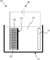
- the apparatus structure is not particularly limited, for example, the bulk reforming can be performed using the bulk reforming apparatus 20 shown in FIG.
- the reformer 20 in the bulk is disposed in the bathtub 27 filled with the organic solvent 23, the positive electrode (lithium source) 21 disposed in the bathtub 27 and connected to one of the power sources 26, and the bathtub 27. It has a powder storage container 25 connected to the other side of the power source 26 and a separator 24 provided between the positive electrode 21 and the powder storage container 25.
- the powder storage container 25 stores a silicon compound powder 22.
- the order of coating with a Li compound such as a carbon coating and LiF on the surface of the silicon compound is not particularly limited.
- negative electrode active material particles in which the Li compound is formed on the outermost surface can be produced by performing bulk modification after performing thermal decomposition CVD.
- negative active material particles having a carbon coating formed on the outermost surface can be prepared by performing thermal decomposition CVD after performing bulk modification.
- the obtained modified particles may not contain a carbon layer.
- organic solvent 23 in the bathtub 27 ethylene carbonate, propylene carbonate, dimethyl carbonate, diethyl carbonate, ethyl methyl carbonate, fluoromethyl methyl carbonate, difluoromethyl methyl carbonate, or the like can be used. Further, as an electrolyte salt contained in the organic solvent 23, lithium hexafluorophosphate (LiPF 6 ), lithium tetrafluoroborate (LiBF 4 ), or the like can be used.
- LiPF 6 lithium hexafluorophosphate
- LiBF 4 lithium tetrafluoroborate
- the positive electrode 21 may use a Li foil or a Li-containing compound.
- the Li-containing compound include lithium carbonate and lithium oxide.
- the negative electrode active material particles are mixed with other materials such as a negative electrode binder and a conductive additive to form a negative electrode mixture, and then a solvent such as an organic solvent or water is added to form a slurry.
- a solvent such as an organic solvent or water
- the aforementioned metal salt and / or substituted ammonium salt is added.
- a mixture slurry is applied to the surface of the negative electrode current collector and dried to form the negative electrode active material layer 12 shown in FIG.
- a heating press or the like may be performed as necessary.
- this negative electrode by changing the SiO 2 component present in the bulk to a stable Li compound, the initial efficiency of the battery is improved, and the stability of the active material accompanying the cycle characteristics is improved. In that case, a higher effect can be obtained when Li silicate is generated inside the bulk.
- the negative electrode active material particles have a layer containing at least one or more of Group 1 and Group 2 metal salts (ions) or substituted ammonium salts (ions) in the periodic table, thereby being resistant to aqueous solvents. Will improve.
- the negative electrode current collector contains carbon and sulfur of 90 ppm or less, higher effects can be obtained.
- Lithium ion secondary battery> a lithium ion secondary battery using the above-described negative electrode for a lithium ion secondary battery will be described.
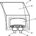
- a laminated film type secondary battery 30 shown in FIG. 3 is one in which a wound electrode body 31 is accommodated mainly in a sheet-like exterior member 35. This wound body has a separator between a positive electrode and a negative electrode and is wound. There is also a case where a laminate is accommodated with a separator between the positive electrode and the negative electrode. In both electrode bodies, the positive electrode lead 32 is attached to the positive electrode, and the negative electrode lead 33 is attached to the negative electrode. The outermost peripheral part of the electrode body is protected by a protective tape.
- the positive and negative electrode leads are led out in one direction from the inside of the exterior member 35 to the outside, for example.
- the positive electrode lead 32 is formed of a conductive material such as aluminum
- the negative electrode lead 33 is formed of a conductive material such as nickel or copper.
- the exterior member 35 is a laminate film in which, for example, a fusion layer, a metal layer, and a surface protective layer are laminated in this order.
- the laminate film is formed by fusing two films so that the fusion layer faces the electrode body 31.
- the outer peripheral edge portions in the adhesion layer are bonded together with an adhesive or the like.
- the fused part is, for example, a film such as polyethylene or polypropylene, and the metal part is aluminum foil or the like.
- the protective layer is, for example, nylon.
- An adhesion film 34 is inserted between the exterior member 35 and the positive and negative electrode leads to prevent intrusion of outside air.
- This material is, for example, polyethylene, polypropylene, polyolefin resin.
- the positive electrode has, for example, a positive electrode active material layer on both sides or one side of the positive electrode current collector, similarly to the negative electrode 10 of FIG.
- the positive electrode current collector is made of, for example, a conductive material such as aluminum.
- the positive electrode active material layer includes one or more of positive electrode materials capable of occluding and releasing lithium ions, and includes other materials such as a binder, a conductive additive, and a dispersant depending on the design. You can leave.
- the binder and the conductive auxiliary agent are the same as, for example, the negative electrode binder and the negative electrode conductive auxiliary agent already described.
- a lithium-containing compound is desirable.
- the lithium-containing compound include a composite oxide composed of lithium and a transition metal element, or a phosphate compound having lithium and a transition metal element.
- compounds having at least one of nickel, iron, manganese, and cobalt are preferable.
- These chemical formulas are represented by, for example, Li x M 1 O 2 or Li y M 2 PO 4 .
- M 1 and M 2 represent at least one transition metal element.
- the values of x and y vary depending on the battery charge / discharge state, but are generally expressed as 0.05 ⁇ x ⁇ 1.10 and 0.05 ⁇ y ⁇ 1.10.
- Examples of the composite oxide having lithium and a transition metal element include, for example, lithium cobalt composite oxide (Li x CoO 2 ), lithium nickel composite oxide (Li x NiO 2 ), and phosphoric acid having lithium and a transition metal element.
- Examples of the compound include a lithium iron phosphate compound (LiFePO 4 ) and a lithium iron manganese phosphate compound (LiFe 1-u Mn u PO 4 (u ⁇ 1)). This is because, when these positive electrode materials are used, a high battery capacity can be obtained and excellent cycle characteristics can be obtained.
- the negative electrode has the same configuration as the above-described negative electrode 10 for a lithium ion secondary battery in FIG. 1.
- the negative electrode has negative electrode active material layers 12 on both surfaces of the current collector 11.
- the negative electrode preferably has a negative electrode charge capacity larger than the electric capacity (charge capacity as a battery) obtained from the positive electrode active material agent. This is because the deposition of lithium metal on the negative electrode can be suppressed.
- the positive electrode active material layer is provided on a part of both surfaces of the positive electrode current collector, and the negative electrode active material layer is also provided on a part of both surfaces of the negative electrode current collector.
- the negative electrode active material layer provided on the negative electrode current collector is provided with a region where there is no opposing positive electrode active material layer. This is for a stable battery design.
- the non-opposing region that is, the region where the negative electrode active material layer and the positive electrode active material layer are not opposed to each other, there is almost no influence of charge / discharge. Therefore, the state of the negative electrode active material layer is maintained as it is immediately after formation. As a result, the composition and the like of the negative electrode active material can be accurately examined with good reproducibility without depending on the presence or absence of charge / discharge.
- the separator separates the positive electrode and the negative electrode, and allows lithium ions to pass through while preventing a short circuit due to the contact between the two electrodes.
- This separator is formed of, for example, a porous film made of synthetic resin or ceramic, and may have a laminated structure in which two or more kinds of porous films are laminated.
- the synthetic resin include polytetrafluoroethylene, polypropylene, and polyethylene.
- Electrode At least a part of the active material layer or the separator is impregnated with a liquid electrolyte (electrolytic solution).
- This electrolytic solution has an electrolyte salt dissolved in a solvent, and may contain other materials such as additives.
- a nonaqueous solvent for example, a nonaqueous solvent can be used.
- the nonaqueous solvent include the following materials. Ethylene carbonate, propylene carbonate, butylene carbonate, dimethyl carbonate, diethyl carbonate, ethyl methyl carbonate, methyl propyl carbonate, 1,2-dimethoxyethane or tetrahydrofuran.
- At least one of ethylene carbonate, propylene carbonate, dimethyl carbonate, diethyl carbonate, and ethyl methyl carbonate is desirable. This is because better characteristics can be obtained. In this case, more advantageous characteristics can be obtained by combining a high viscosity solvent such as ethylene carbonate or propylene carbonate and a low viscosity solvent such as dimethyl carbonate, ethyl methyl carbonate or diethyl carbonate. This is because the dissociation property and ion mobility of the electrolyte salt are improved.
- a halogenated chain carbonate ester or a halogenated cyclic carbonate ester is contained as a solvent. This is because a stable coating is formed on the surface of the negative electrode active material during charging / discharging, particularly during charging.
- the halogenated chain carbonate is a chain carbonate having halogen as a constituent element (at least one hydrogen is replaced by a halogen).
- the halogenated cyclic carbonate is a cyclic carbonate having halogen as a constituent element (at least one hydrogen is replaced by halogen).
- the kind of halogen is not particularly limited, but fluorine is more preferable. This is because a film having a higher quality than other halogens is formed. The larger the number of halogens, the better. This is because the resulting coating is more stable and the decomposition reaction of the electrolytic solution is reduced.
- halogenated chain carbonate ester examples include fluoromethyl methyl carbonate and difluoromethyl methyl carbonate.
- halogenated cyclic carbonate examples include 4-fluoro-1,3-dioxolane-2-one and 4,5-difluoro-1,3-dioxolane-2-one.
- the solvent additive contains an unsaturated carbon bond cyclic carbonate. This is because a stable film is formed on the surface of the negative electrode during charging and discharging, and the decomposition reaction of the electrolytic solution can be suppressed.
- unsaturated carbon bond cyclic ester carbonate include vinylene carbonate and vinyl ethylene carbonate.
- sultone cyclic sulfonic acid ester
- solvent additive examples include propane sultone and propene sultone.
- the solvent preferably contains an acid anhydride. This is because the chemical stability of the electrolytic solution is improved.
- the acid anhydride include propanedisulfonic acid anhydride.
- the electrolyte salt can contain, for example, any one or more of light metal salts such as lithium salts.
- the lithium salt include the following materials. Examples thereof include lithium hexafluorophosphate (LiPF 6 ) and lithium tetrafluoroborate (LiBF 4 ).
- the content of the electrolyte salt is preferably 0.5 mol / kg or more and 2.5 mol / kg or less with respect to the solvent. This is because high ionic conductivity is obtained.
- a positive electrode is manufactured using the positive electrode material described above.
- a positive electrode active material and, if necessary, a binder and a conductive additive are mixed to form a positive electrode mixture, which is then dispersed in an organic solvent to form a positive electrode mixture slurry.
- the mixture slurry is applied to the positive electrode current collector with a coating apparatus such as a die coater having a knife roll or a die head, and dried with hot air to obtain a positive electrode active material layer.
- the positive electrode active material layer is compression molded with a roll press or the like. At this time, heating may be performed. Further, compression and heating may be repeated a plurality of times.
- a negative electrode is produced by forming a negative electrode active material layer on the negative electrode current collector using the same operating procedure as the production of the negative electrode 10 for lithium ion secondary batteries described above.
- a positive electrode and a negative electrode are produced by the same production procedure as described above.
- each active material layer is formed on both surfaces of the positive electrode and the negative electrode current collector.
- the active material application length of both surface portions may be shifted in either electrode (see FIG. 1).
- the positive electrode lead 32 is attached to the positive electrode current collector and the negative electrode lead 33 is attached to the negative electrode current collector by ultrasonic welding or the like. Then, a positive electrode and a negative electrode are laminated
- the adhesion film 34 is inserted between the positive electrode lead 32 and the negative electrode lead 33 and the exterior member 35. A predetermined amount of the adjusted electrolytic solution is introduced from the release portion, and vacuum impregnation is performed. After impregnation, the release part is bonded by a vacuum heat fusion method.
- the laminated film type secondary battery 30 can be manufactured as described above.
- Example 1-1 The laminate film type secondary battery 30 shown in FIG. 3 was produced by the following procedure.
- the positive electrode active material is a mixture of 95 parts by mass of LiCoO 2 which is a lithium cobalt composite oxide, 2.5 parts by mass of a positive electrode conductive additive, and 2.5 parts by mass of a positive electrode binder (polyvinylidene fluoride: PVDF).
- a positive electrode mixture was obtained.
- the positive electrode mixture was dispersed in an organic solvent (N-methyl-2-pyrrolidone: NMP) to obtain a paste slurry.
- NMP N-methyl-2-pyrrolidone
- the slurry was applied to both surfaces of the positive electrode current collector with a coating apparatus having a die head, and dried with a hot air drying apparatus. At this time, the positive electrode current collector had a thickness of 15 ⁇ m.
- compression molding was performed with a roll press.
- the negative electrode active material is a mixture of metal silicon and silicon dioxide, placed in a reactor, and vaporized in a 10 Pa vacuum atmosphere is deposited on the adsorption plate. After cooling sufficiently, the deposit is taken out. It grind
- the produced powder was subjected to bulk modification using an electrochemical method in a 1: 1 mixed solvent of propylene carbonate and ethylene carbonate (containing an electrolyte salt at a concentration of 1.3 mol / kg).
- silica material active material particles and natural graphite were blended at a weight ratio of 5:95.
- Active material made of silica material active material particles and natural graphite, conductive additive 1, conductive additive 2, negative electrode binder 1 (SBR (styrene butadiene rubber)), negative electrode binder 2 (CMC (carboxymethylcellulose) ) was mixed at a dry weight ratio of 90.5 to 92.5: 1: 1: 2.5: 3 to 5, and then diluted with pure water to obtain a negative electrode mixture slurry.
- Group 1 and Group 2 metal salts of the periodic table were added. As the metal salt, lithium carbonate and sodium carbonate were used in combination.
- the negative electrode mixture slurry was applied to both surfaces of the negative electrode current collector with a coating apparatus and then dried.
- an electrolyte salt lithium hexafluorophosphate: LiPF 6
- FEC fluoro-1,3-dioxolan-2-one
- EC ethylene carbonate
- DMC dimethyl carbonate
- an electrolyte salt lithium hexafluorophosphate: LiPF 6
- a secondary battery was assembled as follows. First, an aluminum lead was ultrasonically welded to one end of the positive electrode current collector, and a nickel lead was welded to the negative electrode current collector. Subsequently, a positive electrode, a separator, a negative electrode, and a separator were laminated in this order and wound in the longitudinal direction to obtain a wound electrode body. The end portion was fixed with a PET protective tape. As the separator, a laminated film of 12 ⁇ m sandwiched between a film mainly composed of porous polyethylene and a film mainly composed of porous polypropylene was used.
- the outer peripheral edges except for one side were heat-sealed, and the electrode body was housed inside.
- an aluminum laminated film in which a nylon film, an aluminum foil, and a polypropylene film were laminated was used.
- the prepared electrolyte was injected from the opening, impregnated in a vacuum atmosphere, and then heat-sealed and sealed.
- Example 1-2 to Example 1-5 Comparative Example 1-1 to Comparative Example 1-2
- a secondary battery was fabricated in the same manner as in Example 1-1, except that the amount of oxygen in the bulk of the silicon compound was adjusted.
- silicon compounds represented by SiOx having x values of 0.3 to 1.8 were obtained.
- the amount of oxygen deposited is adjusted by changing the ratio and temperature of the vaporized starting material.
- the silicon compounds in Examples 1-1 to 1-5 and Comparative Examples 1-1 to 1-2 all had the following physical properties.
- the median diameter D 50 of the silicon compound was 5 ⁇ m.
- the full width at half maximum (2 ⁇ ) of the diffraction peak attributed to the (111) crystal plane obtained by X-ray diffraction was 1.22 °, and the crystallite size attributed to the crystal plane (111) was 7.21 nm.
- LiF, Li 2 CO 3 , and Li 2 O are formed as inclusions on the surface, and Li 4 SiO 4 , Li 6 Si 2 O 7 , and Li 2 SiO 3 are formed as inclusions in the active material. It was. In all cases, the carbon content was 5.0% by mass.
- the content ratio of natural graphite (particle diameter 20 ⁇ m) and silicon compound represented by SiOx was 95: 5.
- the metal salt (ion) was located around the carbon material.
- the metal ion concentration in the electrode was 250 ppm in terms of metal ion.
- the cycle characteristics were examined as follows. First, in order to stabilize the battery, charge / discharge was performed for 2 cycles in an atmosphere at 25 ° C., and the discharge capacity at the second cycle was measured. Subsequently, charge and discharge were performed until the total number of cycles reached 100, and the discharge capacity was measured each time. Finally, the discharge capacity at the 100th cycle was divided by the discharge capacity at the second cycle ( ⁇ 100) to calculate the capacity retention rate. As cycling conditions, a constant current density until reaching 4.3V, and charged at 2.5 mA / cm 2, the current density at 4.3V constant voltage at the stage of reaching the voltage charged to reach 0.25 mA / cm 2 . During discharging, discharging was performed at a constant current density of 2.5 mA / cm 2 until the voltage reached 3.0V.
- the initial efficiency (%) (initial discharge capacity / initial charge capacity) ⁇ 100 was calculated.
- the ambient temperature was the same as when the cycle characteristics were examined.
- the charge / discharge conditions were 0.2 times the cycle characteristics.
- the SiO initial efficiency shown in the following Table 1, Table 7, Table 8, and Table 9 does not contain a carbon-based active material such as natural graphite (20 ⁇ m), and only a silicon compound is used as a negative electrode active material.
- the initial efficiency is shown. As a result, it was possible to measure the change in the initial efficiency depending only on the change in SiO (production method, crystallinity, change in median diameter).
- Example 2-1 to 2-15 Adjustment of amount of addition and Raman spectrum peak intensity ratio I 1330 / I 1580 of carbon material (carbon film) coated on silicon compound and added carbon material (carbon-based material) added to negative electrode of the present invention, and added carbon material
- Table 2 shows values such as the peak intensity ratio of the Raman spectrum of the carbon coating and the carbon-based material (negative electrode conductive additive) in Examples 2-1 to 2-15.
- the peak intensity ratio of the carbon coating was adjusted by controlling the pressure and temperature in the furnace when performing pyrolysis CVD.
- the peak intensity ratio of the added carbon species was adjusted by changing the added carbon species to acetylene black, scaly graphite, and glassy carbon.
- I 1330 / I 1580 of the coated carbon is preferably 0.7 ⁇ I 1330 / I 1580 ⁇ 1.5, particularly 0.7 ⁇ I 1330 / I 1580 ⁇ 1.2.
- flaky graphite was preferable to glassy carbon, and acetylene black (median diameter 0.2 ⁇ m) was more preferable than flaky graphite.
- the amount of acetylene black added is preferably 3% or less. As a result, the irreversible capacity of acetylene black itself is not affected, and the initial efficiency is not lowered.
- Examples 3-1 to 3-9 A secondary battery was manufactured in the same manner as in Example 1-3, except that the type and location of ions contained in the negative electrode were changed. The kind of ion was changed by changing the metal salt added to the slurry at the time of preparing the negative electrode. Further, the location of the ions was changed by changing the metal salt addition timing at the time of preparing the negative electrode. For example, after the carbon material and the metal salt are first dispersed in water, the metal salt can be dispersed around the carbon material by adding to the slurry containing the active material and the binder.
- Example 3-1 A secondary battery was manufactured basically in the same manner as in Example 1-3, but tin carbonate was added as a metal salt.
- the battery characteristics were improved when the ion species were group 1 and group 2 metal ions and ammonium ions in the periodic table.
- the metal salt to be added among the Group 1 and Group 2 metal salts of the periodic table, Li salt, Na salt and K salt are preferable, and Li salt and Na salt are particularly preferable. This is because the lithium salt and the sodium salt having an ionic radius close to that of the lithium ion have a high function of suppressing the elution of the Li compound caused by bulk modification of the Si compound.
- the location of the metal salt (ion) is preferably around the carbon material.
- the conductivity of the electrode and the conductivity of the silicon compound as the active material are not deteriorated and the initial efficiency is reduced compared with the case where the electrode is unevenly distributed on the upper part of the electrode or the silicon compound outer shell. This is because there is nothing.
- Li was used as the metal ion species, that is, lithium carbonate was used as the metal salt to be added, and a negative electrode in which the metal salt (ion) was present around the carbon material was used.
- Example 4-1 to 4-6 A secondary battery was manufactured in the same manner as in Example 1-3, except that the metal ion contained in the negative electrode was only lithium ion (Li + ) and the concentration was adjusted. The results are shown in Table 4.
- the concentration of metal ions is 1 ⁇ 10 ⁇ 3 mass% or more, the silicon compound subjected to electrochemical modification can be resistant to water by containing an appropriate amount of metal salt. Therefore, both the maintenance rate and the initial efficiency were good. On the other hand, when the content was 2% by mass or less, erosion of the silicon compound and gelation of the slurry did not occur, and both the maintenance rate and the initial efficiency were good. Accordingly, it was found that the concentration of the metal ions is preferably 1 ⁇ 10 ⁇ 3 mass% or more and 2 mass% or less in terms of metal ions.
- Example 5-5 A secondary battery was manufactured in the same manner as in Example 1-3, except that the binder used for the negative electrode was changed. The results are shown in Table 5.
- the binder As shown in Table 5, as the binder, SBR (styrene-butadiene rubber), CMC (carboxymethylcellulose), PVA (polyvinyl alcohol), PAA (polyacrylic acid), PI (polyimide), PAI (polyamideimide) Etc. can be used. Among them, in particular, the example using the combination of SBR and CMC (Example 5-1) showed good results in both the maintenance rate and the initial efficiency. As described above, the binder preferably contains a carbonyl group, a hydroxy group or an amino group as a functional group, and particularly preferably contains a carbonyl group or a hydroxy group.
- Binder species containing such functional groups are, for example, carboxymethylcellulose and its alkali metal salts, polyacrylic acid and its alkali metal salts, polyvinyl alcohol.
- Example 6-1 and 6-2 A secondary battery was basically manufactured in the same manner as in Example 1-3, but the potential, current amount, and insertion / extraction method of Li during the bulk modification of the silicon compound were controlled.
- the state of inclusions produced in the inventive silicon compound was varied. For example, when electrochemically modified, LiF, Li 2 CO 3 and Li 2 O are generated on the surface, and Li 2 SiO 3 , Li 6 Si 2 O 7 and Li 4 SiO 4 are generated inside. Moreover, the Li compound on the surface can be removed by washing with water. Thereby, in Example 6-1, LiF, Li 2 CO 3 and Li 2 O were formed on the surface of the silicon compound, and Li 2 SiO 3 , Li 6 Si 2 O 7 and Li 4 SiO 4 were formed inside. . In Example 6-2, the Li compound on the surface of the silicon compound was removed, and Li 2 SiO 3 , Li 6 Si 2 O 7 , and Li 4 SiO 4 were present inside.
- the obtained Li compound can be confirmed by XPS.
- Li 4 SiO 4 is given by a binding energy around 532 eV
- Li 2 SiO 3 is given by a binding energy around 530 eV.
- the obtained Li compound can also be confirmed by 29 Si-MAS-NMR spectrum.
- the silicon compound when the silicon compound is electrochemically modified, LiF, Li 2 CO 3 and Li 2 O are formed on the surface, and Li 2 SiO 3 , Li 6 Si 2 O 7 and Li 4 SiO 4 are generated inside. To do. Moreover, the Li compound on the surface can be removed by washing with water. Incorporating these reactions and the like, particularly in Example 6-1, the capacity retention ratio and the initial efficiency were improved by realizing the optimum bulk state. That is, the surface layer of the silicon compound preferably contains LiF, Li 2 CO 3 , and Li 2 O, and the active material contains Li 2 SiO 3 , Li 6 Si 2 O 7 , and Li 4 SiO 4 . It is desirable.
- Example 7-1 In the same manner as in Example 1-3, the silicon compound was modified by an electrochemical method to produce a secondary battery.
- Example 7-2 A secondary battery was manufactured in the same manner as in Example 1-3, except that the silicon compound was modified by the Li thermal doping method.
- the thermal doping method is a technique in which a silicon material and Li metal or a Li compound are mixed and heat-treated, and does not improve the quality of the active material.
- Example 8-1 to 8-6 A secondary battery was manufactured in the same manner as in Example 1-3 except that the crystallinity of the silicon compound was changed.
- the change in crystallinity can be controlled by heat treatment in a non-atmospheric atmosphere after Li insertion and desorption.
- the crystallite size is calculated to be 1.542, but this is a result of fitting using analysis software, and a peak is not substantially obtained. Therefore, it can be said that the silicon compound of Example 8-1 is substantially amorphous.
- Example 9-1 to 9-4 A secondary battery was manufactured in the same manner as in Example 1-3, except that the median diameter of the silicon compound was changed.
- Example 10-1 to 10-6 Except that the ratio of the content of the silicon compound and the carbon-based active material in the negative electrode (the ratio of the silicon compound (SiO material) to the active material) was changed, and the binder was changed according to the ratio, A secondary battery was manufactured in the same manner as in Example 1-3.
- Example 10-1 A secondary battery was manufactured in the same manner as in Example 1-3, except that only the carbon-based active material material was used as the negative electrode active material without containing a silicon compound.
- the relative power capacity density is the power capacity density when the SiO material active material ratio is 0, combined with an NCA (lithium nickel cobalt aluminum composite oxide) positive electrode material, and the discharge cutoff voltage in the battery is 2.5V.
- Comparative Example 10-1 is shown as a reference. Decreasing the proportion of silicon compound improves the initial efficiency and maintenance rate, but decreases the power capacity density. In particular, when only the carbon-based active material is used as the negative electrode active material as in Comparative Example 10-1, a lithium ion secondary battery having a high power capacity density cannot be obtained.
- the carbon material (carbon-based active material) in the negative electrode active material layer has a size equal to or greater than that of the silicon compound. This is because when the silicon material that expands and contracts is smaller than the carbon material, there is no possibility of causing destruction of the composite material layer.
- the particle size of the carbon material is larger than the particle size of the silicon compound, the negative electrode volume density and initial efficiency during charging are improved, and the battery energy density is increased.
- the present invention is not limited to the above embodiment.
- the above-described embodiment is an exemplification, and the present invention has substantially the same configuration as the technical idea described in the claims of the present invention, and any device that exhibits the same function and effect is the present invention. It is included in the technical scope of the invention.
Abstract
Description
前記負極活物質粒子がSiOx(0.5≦x≦1.6)で表されるケイ素化合物を有し、
前記ケイ素化合物が内部にLi化合物を含み、
前記非水電解質二次電池用負極材が、1族及び2族の金属イオン,置換可アンモニウムイオンのうち少なくとも一種以上を含むものであることを特徴とする非水電解質二次電池用負極材を提供する。 In order to achieve the above object, in the present invention, a negative electrode material for a non-aqueous electrolyte secondary battery having negative electrode active material particles,
The negative electrode active material particles have a silicon compound represented by SiO x (0.5 ≦ x ≦ 1.6),
The silicon compound contains a Li compound inside,
Provided is a negative electrode material for a non-aqueous electrolyte secondary battery, wherein the negative electrode material for a non-aqueous electrolyte secondary battery contains at least one of group 1 and group 2 metal ions and substituted ammonium ions. .
SiOx(0.5≦x≦1.6)で表されるケイ素化合物を作製する工程と、
前記ケイ素化合物にLiを挿入することにより、該ケイ素化合物の内部にLi化合物を生成させて該ケイ素化合物を改質し、負極活物質粒子を得る工程と、
前記負極活物質粒子を、1族及び2族の金属の塩,置換可アンモニウム塩のうち少なくとも一種以上並びに溶媒と混合し、スラリーを得る工程と、
前記スラリーを負極集電体の表面に塗布し、乾燥させて負極活物質層を形成する工程と
を有することを特徴とする非水電解質二次電池用負極の製造方法を提供する。 Furthermore, in the present invention, a method for producing a negative electrode for a non-aqueous electrolyte secondary battery,
Producing a silicon compound represented by SiO x (0.5 ≦ x ≦ 1.6);
Inserting Li into the silicon compound to form a Li compound inside the silicon compound to modify the silicon compound to obtain negative electrode active material particles;
Mixing the negative electrode active material particles with at least one of group 1 and group 2 metal salts, substituted ammonium salts, and a solvent to obtain a slurry;
A method of producing a negative electrode for a non-aqueous electrolyte secondary battery, comprising: applying the slurry to a surface of a negative electrode current collector; and drying the slurry to form a negative electrode active material layer.
本発明の非水電解質二次電池用負極材を用いた非水電解質二次電池用負極について説明する。図1は、本発明の一実施形態における非水電解質二次電池用負極(以下、単に「負極」と称することがある。)の断面構成を表している。 <1. Negative electrode for non-aqueous electrolyte secondary battery>
The negative electrode for nonaqueous electrolyte secondary batteries using the negative electrode material for nonaqueous electrolyte secondary batteries of the present invention will be described. FIG. 1 shows a cross-sectional configuration of a negative electrode for a nonaqueous electrolyte secondary battery (hereinafter sometimes simply referred to as “negative electrode”) according to an embodiment of the present invention.
図1に示したように、負極10は、負極集電体11の上に負極活物質層12を有する構成になっている。この負極活物質層12は負極集電体11の両面、又は、片面だけに設けられていても良い。さらに、本発明の負極活物質が用いられたものであれば、負極集電体11はなくてもよい。 [Configuration of negative electrode]
As shown in FIG. 1, the
負極集電体11は、優れた導電性材料であり、かつ、機械的な強度に長けた物で構成される。負極集電体11に用いることができる導電性材料として、例えば銅(Cu)やニッケル(Ni)があげられる。この導電性材料は、リチウム(Li)と金属間化合物を形成しない材料であることが好ましい。 [Negative electrode current collector]
The negative electrode
負極活物質層12は、リチウムイオンを吸蔵,放出可能な複数の粒子状負極活物質(以下、負極活物質粒子と称する)を含んでおり、電池設計上、さらに負極結着剤や導電助剤など、他の材料を含んでいても良い。本発明の非水電解質二次電池用負極材は、この負極活物質層12を構成する材料となる。 [Negative electrode active material layer]
The negative electrode
XPS
・装置: X線光電子分光装置
・X線源: 単色化Al Kα線
・X線スポット径: 100μm
・Arイオン銃スパッタ条件: 0.5kV 2mm×2mm
29Si MAS NMR(マジック角回転核磁気共鳴)
・装置: Bruker社製700NMR分光器
・プローブ: 4mmHR-MASローター 50μL
・試料回転速度: 10kHz
・測定環境温度: 25℃ Li compounds can be quantified by NMR (nuclear magnetic resonance) and XPS (X-ray photoelectron spectroscopy). The XPS and NMR measurements can be performed, for example, under the following conditions.
XPS
・ Device: X-ray photoelectron spectrometer
・ X-ray source: Monochromatic Al Kα ray ・ X-ray spot diameter: 100 μm
Ar ion gun sputtering conditions: 0.5 kV 2 mm x 2 mm
29 Si MAS NMR (magic angle rotating nuclear magnetic resonance)
・ Device: 700 NMR spectrometer manufactured by Bruker ・ Probe: 4 mmHR-MAS rotor 50 μL
・ Sample rotation speed: 10 kHz
・ Measurement environment temperature: 25 ℃
本発明の負極を製造する方法について説明する。まず、SiOx(0.5≦x≦1.6)で表されるケイ素化合物を作製する。次にケイ素化合物にLiを挿入することにより、該ケイ素化合物の内部にLi化合物を生成させて該ケイ素化合物を改質し、負極活物質粒子を得る。次に、負極活物質粒子を、1族及び2族の金属の塩,置換可アンモニウム塩のうち少なくとも一種以上並びに溶媒と混合し、スラリーを得る。次に、スラリーを負極集電体の表面に塗布し、乾燥させて負極活物質層を形成する。 [Production method of negative electrode]
A method for producing the negative electrode of the present invention will be described. First, a silicon compound represented by SiO x (0.5 ≦ x ≦ 1.6) is produced. Next, by inserting Li into the silicon compound, a Li compound is generated inside the silicon compound to modify the silicon compound to obtain negative electrode active material particles. Next, the negative electrode active material particles are mixed with at least one or more of Group 1 and Group 2 metal salts and substituted ammonium salts and a solvent to obtain a slurry. Next, the slurry is applied to the surface of the negative electrode current collector and dried to form a negative electrode active material layer.
次に、上記したリチウムイオン二次電池用負極を用いたリチウムイオン二次電池について説明する。 <2. Lithium ion secondary battery>
Next, a lithium ion secondary battery using the above-described negative electrode for a lithium ion secondary battery will be described.
図3に示すラミネートフィルム型二次電池30は、主にシート状の外装部材35の内部に巻回電極体31が収納されたものである。この巻回体は正極,負極間にセパレータを有し、巻回されたものである。また正極,負極間にセパレータを有し積層体を収納した場合も存在する。どちらの電極体においても、正極に正極リード32が取り付けられ、負極に負極リード33が取り付けられている。電極体の最外周部は保護テープにより保護されている。 [Configuration of laminated film type secondary battery]
A laminated film type
正極は、例えば、図1の負極10と同様に、正極集電体の両面又は片面に正極活物質層を有している。 [Positive electrode]
The positive electrode has, for example, a positive electrode active material layer on both sides or one side of the positive electrode current collector, similarly to the
負極は、上記した図1のリチウムイオン二次電池用負極10と同様の構成を有し、例えば、集電体11の両面に負極活物質層12を有している。この負極は、正極活物質剤から得られる電気容量(電池として充電容量)に対して、負極充電容量が大きくなることが好ましい。負極上でのリチウム金属の析出を抑制することができるためである。 [Negative electrode]
The negative electrode has the same configuration as the above-described
セパレータは正極,負極を隔離し、両極接触に伴う電流短絡を防止しつつ、リチウムイオンを通過させるものである。このセパレータは、例えば合成樹脂、あるいはセラミックからなる多孔質膜により形成されており、2種以上の多孔質膜が積層された積層構造を有しても良い。合成樹脂として例えば、ポリテトラフルオロエチレン,ポリプロピレンあるいはポリエチレンなどが挙げられる。 [Separator]
The separator separates the positive electrode and the negative electrode, and allows lithium ions to pass through while preventing a short circuit due to the contact between the two electrodes. This separator is formed of, for example, a porous film made of synthetic resin or ceramic, and may have a laminated structure in which two or more kinds of porous films are laminated. Examples of the synthetic resin include polytetrafluoroethylene, polypropylene, and polyethylene.
活物質層の少なくとも一部、又はセパレータには液状の電解質(電解液)が含浸されている。この電解液は、溶媒中に電解質塩が溶解されており、添加剤など他の材料を含んでいても良い。 [Electrolyte]
At least a part of the active material layer or the separator is impregnated with a liquid electrolyte (electrolytic solution). This electrolytic solution has an electrolyte salt dissolved in a solvent, and may contain other materials such as additives.
最初に上記した正極材を用い正極電極を作製する。まず、正極活物質と、必要に応じて結着剤,導電助剤などを混合し正極合剤としたのち、有機溶剤に分散させ正極合剤スラリーとする。続いて、ナイフロールまたはダイヘッドを有するダイコーターなどのコーティング装置で正極集電体に合剤スラリーを塗布し、熱風乾燥させて正極活物質層を得る。最後に、ロールプレス機などで正極活物質層を圧縮成型する。この時、加熱を行っても良い。また、圧縮、加熱を複数回繰り返しても良い。 [Production method of laminated film type secondary battery]
First, a positive electrode is manufactured using the positive electrode material described above. First, a positive electrode active material and, if necessary, a binder and a conductive additive are mixed to form a positive electrode mixture, which is then dispersed in an organic solvent to form a positive electrode mixture slurry. Subsequently, the mixture slurry is applied to the positive electrode current collector with a coating apparatus such as a die coater having a knife roll or a die head, and dried with hot air to obtain a positive electrode active material layer. Finally, the positive electrode active material layer is compression molded with a roll press or the like. At this time, heating may be performed. Further, compression and heating may be repeated a plurality of times.
以下の手順により、図3に示したラミネートフィルム型の二次電池30を作製した。 Example 1-1
The laminate film type
ケイ素化合物のバルク内酸素量を調整した以外は、実施例1-1と同様に、二次電池を作製した。その結果、SiOxで表されるケイ素化合物において、xの値が、0.3~1.8のものがそれぞれ得られた。この場合、気化出発材の比率や温度を変化させ堆積される酸素量を調整している。 (Example 1-2 to Example 1-5, Comparative Example 1-1 to Comparative Example 1-2)
A secondary battery was fabricated in the same manner as in Example 1-1, except that the amount of oxygen in the bulk of the silicon compound was adjusted. As a result, silicon compounds represented by SiOx having x values of 0.3 to 1.8 were obtained. In this case, the amount of oxygen deposited is adjusted by changing the ratio and temperature of the vaporized starting material.

ケイ素化合物に被覆する炭素材(炭素被膜)及び本発明の負極に添加する添加炭素材(炭素系材料)の、添加量及びラマンスペクトルのピーク強度比I1330/I1580の調整、並びに添加炭素材の種類及びメディアン径を変更したことを除き、実施例1-3と同様に、二次電池の製造を行った。実施例2-1~2-15における、炭素被膜及び炭素系材料(負極導電助剤)のラマンスペクトルのピーク強度比等の値を表2中に示した。尚、炭素被膜のピーク強度比は、熱分解CVDを行う際、炉内の圧力、温度を制御することによって調整した。また、添加炭素種のピーク強度比は、添加炭素種をアセチレンブラック、鱗片状黒鉛およびグラッシーカーボンに変えることで調整した。 (Examples 2-1 to 2-15)
Adjustment of amount of addition and Raman spectrum peak intensity ratio I 1330 / I 1580 of carbon material (carbon film) coated on silicon compound and added carbon material (carbon-based material) added to negative electrode of the present invention, and added carbon material A secondary battery was manufactured in the same manner as in Example 1-3 except that the type and the median diameter were changed. Table 2 shows values such as the peak intensity ratio of the Raman spectrum of the carbon coating and the carbon-based material (negative electrode conductive additive) in Examples 2-1 to 2-15. The peak intensity ratio of the carbon coating was adjusted by controlling the pressure and temperature in the furnace when performing pyrolysis CVD. The peak intensity ratio of the added carbon species was adjusted by changing the added carbon species to acetylene black, scaly graphite, and glassy carbon.

負極に含まれるイオンの種類、及び所在を変化させたことを除き、実施例1-3と同様に、二次電池の製造を行った。イオンの種類は負極作成時のスラリーに加える金属塩を変更することで変化させた。また、イオンの所在は、負極作成時の金属塩添加タイミングを変えることで変化させた。例えば、炭素材と金属塩を先に水に分散した後、活物質、バインダーを含むスラリーに添加することで、炭素材周辺に金属塩を分散させることが可能である。 (Examples 3-1 to 3-9)
A secondary battery was manufactured in the same manner as in Example 1-3, except that the type and location of ions contained in the negative electrode were changed. The kind of ion was changed by changing the metal salt added to the slurry at the time of preparing the negative electrode. Further, the location of the ions was changed by changing the metal salt addition timing at the time of preparing the negative electrode. For example, after the carbon material and the metal salt are first dispersed in water, the metal salt can be dispersed around the carbon material by adding to the slurry containing the active material and the binder.
基本的に実施例1-3と同様に二次電池の製造を行ったが、金属塩として炭酸スズを添加した。 (Comparative Example 3-1)
A secondary battery was manufactured basically in the same manner as in Example 1-3, but tin carbonate was added as a metal salt.

負極に含まれる金属イオンをリチウムイオン(Li+)のみとし、その濃度を調整したことを除き、実施例1-3と同様に、二次電池の製造を行った。結果を表4に示す。 (Examples 4-1 to 4-6)
A secondary battery was manufactured in the same manner as in Example 1-3, except that the metal ion contained in the negative electrode was only lithium ion (Li + ) and the concentration was adjusted. The results are shown in Table 4.

負極に用いる結着材を変化させたことを除き、実施例1-3と同様に、二次電池の製造を行った。結果を表5に示す。 (Examples 5-1 to 5-5)
A secondary battery was manufactured in the same manner as in Example 1-3, except that the binder used for the negative electrode was changed. The results are shown in Table 5.

基本的に実施例1-3と同様に二次電池の製造を行ったが、ケイ素化合物のバルク改質時の、Li化合物作製時の電位,電流量,Liの挿入離脱手法を制御し、本発明のケイ素化合物に生成される含有物の状態を変化させた。例えば、電気化学的に改質すると、LiF,Li2CO3,Li2Oが表面に、内部にLi2SiO3,Li6Si2O7,Li4SiO4が生成する。また、水洗することで表面のLi化合物を除去することができる。これにより、実施例6-1では、ケイ素化合物表面にLiF、Li2CO3、Li2Oが、内部にLi2SiO3、Li6Si2O7、Li4SiO4が生成した状態とした。実施例6-2では、ケイ素化合物の表面のLi化合物を除去し、内部にLi2SiO3、Li6Si2O7、Li4SiO4が存在する状態とした。 (Examples 6-1 and 6-2)
A secondary battery was basically manufactured in the same manner as in Example 1-3, but the potential, current amount, and insertion / extraction method of Li during the bulk modification of the silicon compound were controlled. The state of inclusions produced in the inventive silicon compound was varied. For example, when electrochemically modified, LiF, Li 2 CO 3 and Li 2 O are generated on the surface, and Li 2 SiO 3 , Li 6 Si 2 O 7 and Li 4 SiO 4 are generated inside. Moreover, the Li compound on the surface can be removed by washing with water. Thereby, in Example 6-1, LiF, Li 2 CO 3 and Li 2 O were formed on the surface of the silicon compound, and Li 2 SiO 3 , Li 6 Si 2 O 7 and Li 4 SiO 4 were formed inside. . In Example 6-2, the Li compound on the surface of the silicon compound was removed, and Li 2 SiO 3 , Li 6 Si 2 O 7 , and Li 4 SiO 4 were present inside.
基本的に実施例1-3と同様に二次電池の製造を行ったが、ケイ素化合物のバルク改質を行わなかった。 (Comparative Example 6-1)
A secondary battery was manufactured basically in the same manner as in Example 1-3, but the bulk modification of the silicon compound was not performed.

実施例1-3と同様に、ケイ素化合物の改質を電気化学的手法により行い、二次電池を製造した。 Example 7-1
In the same manner as in Example 1-3, the silicon compound was modified by an electrochemical method to produce a secondary battery.
ケイ素化合物の改質をLiの熱ドープ法により行った他は、実施例1-3と同様に二次電池を製造した。 (Example 7-2)
A secondary battery was manufactured in the same manner as in Example 1-3, except that the silicon compound was modified by the Li thermal doping method.
ケイ素化合物へのLi導入をせず改質を行わないことの他は、実施例1-3と同様に二次電池を製造した。 (Comparative Example 7-1)
A secondary battery was manufactured in the same manner as in Example 1-3, except that no modification was performed without introducing Li into the silicon compound.

ケイ素化合物の結晶性を変化させた他は、実施例1-3と同様に二次電池の製造を行った。結晶性の変化はLiの挿入、脱離後の非大気雰囲気下の熱処理で制御可能である。実施例8-1では結晶子サイズを1.542と算出しているが、解析ソフトを用いフィッティングした結果であり、実質的にピークは得られていない。よって実施例8-1のケイ素化合物は実質的に非晶質であると言える。 (Examples 8-1 to 8-6)
A secondary battery was manufactured in the same manner as in Example 1-3 except that the crystallinity of the silicon compound was changed. The change in crystallinity can be controlled by heat treatment in a non-atmospheric atmosphere after Li insertion and desorption. In Example 8-1, the crystallite size is calculated to be 1.542, but this is a result of fitting using analysis software, and a peak is not substantially obtained. Therefore, it can be said that the silicon compound of Example 8-1 is substantially amorphous.

ケイ素化合物のメディアン径を変化させたことを除き、実施例1-3と同様に、二次電池の製造を行った。 (Examples 9-1 to 9-4)
A secondary battery was manufactured in the same manner as in Example 1-3, except that the median diameter of the silicon compound was changed.

負極中のケイ素化合物及び炭素系活物質材の含有量の比(ケイ素化合物(SiO材)の活物質に占める割合)を変化させ、その割合に応じて結着剤も変化させたことを除き、実施例1-3と同様に、二次電池の製造を行った。 (Examples 10-1 to 10-6)
Except that the ratio of the content of the silicon compound and the carbon-based active material in the negative electrode (the ratio of the silicon compound (SiO material) to the active material) was changed, and the binder was changed according to the ratio, A secondary battery was manufactured in the same manner as in Example 1-3.
ケイ素化合物を含有せず、炭素系活物質材のみを負極活物質として使用した他は、実施例1-3と同様に二次電池を製造した。 (Comparative Example 10-1)
A secondary battery was manufactured in the same manner as in Example 1-3, except that only the carbon-based active material material was used as the negative electrode active material without containing a silicon compound.

Claims (20)
- 負極活物質粒子を有する非水電解質二次電池用負極材であって、
前記負極活物質粒子がSiOx(0.5≦x≦1.6)で表されるケイ素化合物を有し、
前記ケイ素化合物が内部にLi化合物を含み、
前記非水電解質二次電池用負極材が、1族及び2族の金属イオン,置換可アンモニウムイオンのうち少なくとも一種以上を含むものであることを特徴とする非水電解質二次電池用負極材。 A negative electrode material for a non-aqueous electrolyte secondary battery having negative electrode active material particles,
The negative electrode active material particles have a silicon compound represented by SiO x (0.5 ≦ x ≦ 1.6),
The silicon compound contains a Li compound inside,
The negative electrode material for a non-aqueous electrolyte secondary battery includes at least one of group 1 and group 2 metal ions and substituted ammonium ions. - 前記ケイ素化合物は、少なくとも一部に炭素被膜が形成されたものであり、該炭素被膜が、ラマンスペクトル分析において、1330cm-1と1580cm-1に散乱ピークを有し、それらの強度比I1330/I1580が0.7<I1330/I1580<2.0を満たすものであることを特徴とする請求項1に記載の非水電解質二次電池用負極材。 The silicon compound are those carbon coating on at least part of which is formed, the carbon coating is in the Raman spectrum analysis, have a scattering peak at 1330 cm -1 and 1580 cm -1, their intensity ratio I 1330 / I 1580 is 0.7 <I 1330 / I 1580 < 2.0 , characterized in that satisfies the claims 1 negative electrode material for non-aqueous electrolyte secondary battery according to.
- 前記負極活物質粒子の周囲に、前記ケイ素化合物よりメディアン径の小さい炭素系材料を少なくとも一部に有し、該炭素系材料が、ラマンスペクトル分析において、1330cm-1と1580cm-1に散乱ピークを有し、それらの強度比I1330/I1580が0.3<I1330/I1580<1.2を満たすものであることを特徴とする請求項1又は請求項2に記載の非水電解質二次電池用負極材。 Around the anode active material particles have at least in part smaller carbon-based material having a median diameter than the silicon compound, carbon Motokei material, in the Raman spectrum analysis, the scattering peak in 1330 cm -1 and 1580 cm -1 The non-aqueous electrolyte according to claim 1, wherein the strength ratio I 1330 / I 1580 satisfies 0.3 <I 1330 / I 1580 <1.2. Negative electrode material for secondary batteries.
- 前記イオンが、前記炭素被膜及び/又は前記炭素系材料の周囲に存在することを特徴とする請求項3に記載の非水電解質二次電池用負極材。 The negative electrode material for a non-aqueous electrolyte secondary battery according to claim 3, wherein the ions are present around the carbon coating and / or the carbon-based material.
- 前記イオンが、金属の塩及び/又は置換可アンモニウム塩の形で添加されたものであることを特徴とする請求項1から請求項4のいずれか1項に記載の非水電解質二次電池用負極材。 5. The non-aqueous electrolyte secondary battery according to claim 1, wherein the ions are added in the form of a metal salt and / or a substituted ammonium salt. 6. Negative electrode material.
- 前記金属の塩が、リチウム塩,ナトリウム塩及びカリウム塩のうちの少なくとも1つを含むことを特徴とする請求項5に記載の非水電解質二次電池用負極材。 The negative electrode material for a non-aqueous electrolyte secondary battery according to claim 5, wherein the metal salt includes at least one of a lithium salt, a sodium salt, and a potassium salt.
- 更に、官能基としてカルボニル基,ヒドロキシ基及びアミノ基のうちの少なくとも1つを含む結着剤を含有するものであることを特徴とする請求項1から請求項6のいずれか1項に記載の非水電解質二次電池用負極材。 The binder according to any one of claims 1 to 6, further comprising a binder containing at least one of a carbonyl group, a hydroxy group, and an amino group as a functional group. A negative electrode material for non-aqueous electrolyte secondary batteries.
- 前記結着剤が、カルボキシメチルセルロース及びそのアルカリ金属塩,ポリアクリル酸及びそのアルカリ金属塩並びにポリビニルアルコールのうちの少なくとも1つを含むことを特徴とする請求項7に記載の非水電解質二次電池用負極材。 The non-aqueous electrolyte secondary battery according to claim 7, wherein the binder includes at least one of carboxymethyl cellulose and an alkali metal salt thereof, polyacrylic acid and an alkali metal salt thereof, and polyvinyl alcohol. Negative electrode material.
- 前記ケイ素化合物の表層にLi2CO3,Li2O,LiOH及びLiFのうちの少なくとも1つのLi化合物が存在することを特徴とする請求項1から請求項8のいずれか1項に記載の非水電解質二次電池用負極材。 9. The non-reactive material according to claim 1, wherein at least one Li compound of Li 2 CO 3 , Li 2 O, LiOH, and LiF is present on a surface layer of the silicon compound. Negative electrode material for water electrolyte secondary battery.
- 前記ケイ素化合物の内部にLi2SiO3,Li6Si2O7及びLi4SiO4のうちの少なくとも1つのLi化合物が存在することを特徴とする請求項1から請求項9のいずれか1項に記載の非水電解質二次電池用負極材。 Inside Li 2 SiO 3, Li 6 Si 2 O 7 and Li 4 any one of claims 1 to 9 in which at least one of Li compounds of the SiO 4 is characterized by the presence of the silicon compound A negative electrode material for a non-aqueous electrolyte secondary battery according to 1.
- 前記炭素被膜の含有率が、前記ケイ素化合物及び前記炭素被膜の合計に対し20質量%以下であることを特徴とする請求項2から請求項10のいずれか1項に記載の非水電解質二次電池用負極材。 The nonaqueous electrolyte secondary according to any one of claims 2 to 10, wherein a content of the carbon coating is 20% by mass or less based on a total of the silicon compound and the carbon coating. Negative electrode material for batteries.
- 前記負極活物質粒子のX線回折により得られる(111)結晶面に起因する回折ピークの半値幅(2θ)が1.2°以上であり、その結晶面に起因する結晶子サイズが7.5nm以下であることを特徴とする請求項1から請求項11のいずれか1項に記載の非水電解質二次電池用負極材。 The half-value width (2θ) of the diffraction peak attributed to the (111) crystal plane obtained by X-ray diffraction of the negative electrode active material particles is 1.2 ° or more, and the crystallite size attributed to the crystal plane is 7.5 nm. The negative electrode material for a nonaqueous electrolyte secondary battery according to any one of claims 1 to 11, wherein the negative electrode material is the following.
- 前記負極活物質粒子のメディアン径が、0.5μm以上20μm以下であることを特徴とする請求項1から請求項12のいずれか1項に記載の非水電解質二次電池用負極材。 The negative electrode material for a nonaqueous electrolyte secondary battery according to any one of claims 1 to 12, wherein a median diameter of the negative electrode active material particles is 0.5 µm or more and 20 µm or less.
- 前記負極活物質粒子が、電気化学的手法を含む方法で作製されたものであることを特徴とする請求項1から請求項13のいずれか1項に記載の非水電解質二次電池用負極材。 14. The negative electrode material for a non-aqueous electrolyte secondary battery according to claim 1, wherein the negative electrode active material particles are produced by a method including an electrochemical technique. .
- 前記イオンの濃度が、金属イオン又はアンモニウムイオン換算で1×10⁻³質量%以上2質量%以下であることを特徴とする請求項1から請求項14のいずれか1項に記載の非水電解質二次電池用負極材。 15. The nonaqueous electrolyte according to claim 1, wherein the ion concentration is 1 × 10 −3 mass% or more and 2 mass% or less in terms of metal ion or ammonium ion. Secondary battery negative electrode material.
- 請求項1から請求項15のいずれか1項に記載の非水電解質二次電池用負極材を用いたことを特徴とする非水電解質二次電池用負極。 A negative electrode for a nonaqueous electrolyte secondary battery using the negative electrode material for a nonaqueous electrolyte secondary battery according to any one of claims 1 to 15.
- 更に、炭素系活物質材を含むものであることを特徴とする請求項16に記載の非水電解質二次電池用負極。 The negative electrode for a non-aqueous electrolyte secondary battery according to claim 16, further comprising a carbon-based active material.
- 前記ケイ素化合物の含有量が、前記炭素系活物質材に対し、質量比で5%以上90%未満であることを特徴とする請求項17に記載の非水電解質二次電池用負極。 The negative electrode for a nonaqueous electrolyte secondary battery according to claim 17, wherein the content of the silicon compound is 5% or more and less than 90% by mass ratio with respect to the carbon-based active material.
- 請求項16から請求項18のいずれか1項に記載の負極を用いたことを特徴とする非水電解質二次電池。 A nonaqueous electrolyte secondary battery using the negative electrode according to any one of claims 16 to 18.
- 非水電解質二次電池用負極の製造方法であって、
SiOx(0.5≦x≦1.6)で表されるケイ素化合物を作製する工程と、
前記ケイ素化合物にLiを挿入することにより、該ケイ素化合物の内部にLi化合物を生成させて該ケイ素化合物を改質し、負極活物質粒子を得る工程と、
前記負極活物質粒子を、1族及び2族の金属の塩,置換可アンモニウム塩のうち少なくとも一種以上並びに溶媒と混合し、スラリーを得る工程と、
前記スラリーを負極集電体の表面に塗布し、乾燥させて負極活物質層を形成する工程と
を有することを特徴とする非水電解質二次電池用負極の製造方法。 A method for producing a negative electrode for a nonaqueous electrolyte secondary battery, comprising:
Producing a silicon compound represented by SiO x (0.5 ≦ x ≦ 1.6);
Inserting Li into the silicon compound to form a Li compound inside the silicon compound to modify the silicon compound to obtain negative electrode active material particles;
Mixing the negative electrode active material particles with at least one of group 1 and group 2 metal salts, substituted ammonium salts, and a solvent to obtain a slurry;
Applying the slurry to the surface of the negative electrode current collector and drying to form a negative electrode active material layer.
Priority Applications (4)
| Application Number | Priority Date | Filing Date | Title |
|---|---|---|---|
| CN201580007537.3A CN105981203B (en) | 2014-02-07 | 2015-01-30 | The manufacturing method and non-aqueous electrolyte secondary battery of negative electrode material for nonaqueous electrode secondary battery, anode for nonaqueous electrolyte secondary battery and anode for nonaqueous electrolyte secondary battery |
| EP15746363.9A EP3104439B1 (en) | 2014-02-07 | 2015-01-30 | Negative electrode material for non-aqueous electrolyte secondary battery, negative electrode for non-aqueous electrolyte secondary battery, production method therefor, and non-aqueous electrolyte secondary battery |
| KR1020167021229A KR102277198B1 (en) | 2014-02-07 | 2015-01-30 | Negative electrode material for non-aqueous electrolyte secondary battery, negative electrode for non-aqueous electrolyte secondary battery, production method therefor, and non-aqueous electrolyte secondary battery |
| US15/114,686 US10199678B2 (en) | 2014-02-07 | 2015-01-30 | Negative electrode material for non-aqueous electrolyte secondary battery, negative electrode for non-aqueous electrolyte secondary battery and method of producing the same, and non-aqueous electrolyte secondary battery |
Applications Claiming Priority (2)
| Application Number | Priority Date | Filing Date | Title |
|---|---|---|---|
| JP2014022200A JP6359836B2 (en) | 2014-02-07 | 2014-02-07 | Negative electrode material for nonaqueous electrolyte secondary battery, negative electrode for nonaqueous electrolyte secondary battery, method for producing the same, and nonaqueous electrolyte secondary battery |
| JP2014-022200 | 2014-02-07 |
Publications (1)
| Publication Number | Publication Date |
|---|---|
| WO2015118846A1 true WO2015118846A1 (en) | 2015-08-13 |
Family
ID=53777661
Family Applications (1)
| Application Number | Title | Priority Date | Filing Date |
|---|---|---|---|
| PCT/JP2015/000424 WO2015118846A1 (en) | 2014-02-07 | 2015-01-30 | Negative electrode material for non-aqueous electrolyte secondary battery, negative electrode for non-aqueous electrolyte secondary battery, production method therefor, and non-aqueous electrolyte secondary battery |
Country Status (6)
| Country | Link |
|---|---|
| US (1) | US10199678B2 (en) |
| EP (1) | EP3104439B1 (en) |
| JP (1) | JP6359836B2 (en) |
| KR (1) | KR102277198B1 (en) |
| CN (1) | CN105981203B (en) |
| WO (1) | WO2015118846A1 (en) |
Cited By (8)
| Publication number | Priority date | Publication date | Assignee | Title |
|---|---|---|---|---|
| JP2017050247A (en) * | 2015-09-04 | 2017-03-09 | イビデン株式会社 | Method for manufacturing alkali-metal ion predoped active material powder |
| JP2017050248A (en) * | 2015-09-04 | 2017-03-09 | イビデン株式会社 | Method for manufacturing sei film-coated negative electrode active material powder |
| WO2017094712A1 (en) * | 2015-11-30 | 2017-06-08 | 日本電気株式会社 | Lithium ion secondary battery |
| CN108701826A (en) * | 2016-03-29 | 2018-10-23 | 株式会社大阪钛技术 | Monox powder containing Li |
| US20190010057A1 (en) * | 2016-01-14 | 2019-01-10 | Lg Chem, Ltd. | Negative electrode active material for lithium secondary battery and method of preparing the same |
| EP3404750A4 (en) * | 2016-02-15 | 2019-06-26 | Shin-Etsu Chemical Co., Ltd. | Anode active material, mixed anode active material ingredient, anode for nonaqueous electrolytic secondary battery, lithium ion secondary battery, and method for manufacturing anode active material |
| US10707519B2 (en) | 2015-11-30 | 2020-07-07 | Nec Corporation | Lithium ion secondary battery |
| CN115820013A (en) * | 2022-07-26 | 2023-03-21 | 宁德时代新能源科技股份有限公司 | Battery case, preparation method thereof, secondary battery and power utilization device |
Families Citing this family (27)
| Publication number | Priority date | Publication date | Assignee | Title |
|---|---|---|---|---|
| JP2016072035A (en) * | 2014-09-29 | 2016-05-09 | 株式会社Gsユアサ | Nonaqueous electrolyte power storage device |
| JP6596405B2 (en) * | 2016-02-24 | 2019-10-23 | 信越化学工業株式会社 | Negative electrode active material for nonaqueous electrolyte secondary battery, nonaqueous electrolyte secondary battery, and method for producing negative electrode material for nonaqueous electrolyte secondary battery |
| JP7019284B2 (en) * | 2016-04-06 | 2022-02-15 | 信越化学工業株式会社 | Negative electrode active material, mixed negative electrode active material, and method for manufacturing negative electrode active material |
| JP6719262B2 (en) * | 2016-04-18 | 2020-07-08 | 信越化学工業株式会社 | Negative electrode active material, mixed negative electrode active material, and method for producing negative electrode active material |
| JP6575786B2 (en) | 2016-08-18 | 2019-09-18 | 三井化学株式会社 | Non-aqueous electrolyte secondary battery negative electrode, non-aqueous electrolyte secondary battery, and method for producing negative electrode for non-aqueous electrolyte secondary battery |
| WO2018061536A1 (en) * | 2016-09-30 | 2018-04-05 | 信越化学工業株式会社 | Negative electrode active material, mixed negative electrode active material substance, and method for producing negative electrode active material |
| JP6797739B2 (en) * | 2016-09-30 | 2020-12-09 | 信越化学工業株式会社 | Negative electrode active material, mixed negative electrode active material, and method for manufacturing negative electrode active material |
| CN110024189B (en) * | 2016-11-22 | 2022-08-30 | 三菱化学株式会社 | Negative electrode material for nonaqueous secondary battery, negative electrode for nonaqueous secondary battery, and nonaqueous secondary battery |
| KR102132725B1 (en) | 2016-12-23 | 2020-07-10 | 주식회사 엘지화학 | An anode active material and an anode for an electrochemical device comprising the same |
| JP6876996B2 (en) * | 2016-12-28 | 2021-05-26 | パナソニックIpマネジメント株式会社 | Non-aqueous electrolyte secondary battery |
| JP7029680B2 (en) * | 2017-03-30 | 2022-03-04 | パナソニックIpマネジメント株式会社 | Negative electrode material and non-aqueous electrolyte secondary battery |
| JP6964386B2 (en) * | 2017-08-03 | 2021-11-10 | 信越化学工業株式会社 | Method for manufacturing negative electrode active material for non-aqueous electrolyte secondary battery, non-aqueous electrolyte secondary battery, and negative electrode material for non-aqueous electrolyte secondary battery |
| US10601033B2 (en) | 2017-09-29 | 2020-03-24 | International Business Machines Corporation | High-performance rechargeable batteries having a spalled and textured cathode layer |
| US10622636B2 (en) * | 2017-09-29 | 2020-04-14 | International Business Machines Corporation | High-capacity rechargeable battery stacks containing a spalled cathode material |
| WO2019078680A2 (en) * | 2017-10-19 | 2019-04-25 | 주식회사 엘지화학 | Method for producing negative active material |
| KR102290960B1 (en) | 2017-10-19 | 2021-08-20 | 주식회사 엘지에너지솔루션 | Method for preparing negative electrode active material |
| US11296312B2 (en) * | 2017-12-08 | 2022-04-05 | Lg Energy Solution, Ltd. | Negative electrode active material for lithium secondary battery and method for preparing the same |
| KR102328257B1 (en) | 2017-12-27 | 2021-11-18 | 주식회사 엘지에너지솔루션 | Binder for lithium-sulfur battery, positive electrode and lithium-sulfur battery comprising the same |
| JP6960092B2 (en) * | 2018-09-10 | 2021-11-05 | トヨタ自動車株式会社 | Solid state battery |
| CN110970600B (en) * | 2018-09-28 | 2023-06-30 | 贝特瑞新材料集团股份有限公司 | Lithium ion secondary battery negative electrode material, and preparation method and application thereof |
| CN109671943B (en) * | 2018-12-26 | 2021-11-23 | 成都爱敏特新能源技术有限公司 | High-first-efficiency silicon-carbon composite negative electrode material and preparation method thereof |
| CN111029543B (en) * | 2019-11-28 | 2022-02-15 | 宁德新能源科技有限公司 | Negative electrode material, and electrochemical device and electronic device comprising same |
| EP3965189A4 (en) * | 2020-03-26 | 2022-06-29 | Ningde Amperex Technology Limited | Negative electrode material, negative electrode plate, electrochemical device and electronic device |
| CN111342031B (en) * | 2020-03-28 | 2022-11-29 | 兰溪致德新能源材料有限公司 | Multi-element gradient composite high-first-efficiency lithium battery negative electrode material and preparation method thereof |
| KR20230117625A (en) * | 2020-12-28 | 2023-08-08 | 닝더 엠프렉스 테크놀로지 리미티드 | A cathode pole piece, an electrochemical device and an electronic device including the cathode pole piece |
| JP2024500499A (en) * | 2020-12-28 | 2024-01-09 | 寧徳新能源科技有限公司 | Negative electrode piece, electrochemical device and electronic device including the negative electrode piece |
| KR20230033489A (en) * | 2021-09-01 | 2023-03-08 | 삼성에스디아이 주식회사 | Negative electrode for rechargeable lithium battery and rechargeable lithium battery including same |
Citations (14)
| Publication number | Priority date | Publication date | Assignee | Title |
|---|---|---|---|---|
| JP2997741B2 (en) | 1992-07-29 | 2000-01-11 | セイコーインスツルメンツ株式会社 | Non-aqueous electrolyte secondary battery and method of manufacturing the same |
| JP2001185127A (en) | 1999-12-24 | 2001-07-06 | Fdk Corp | Lithium secondary battery |
| JP2002042806A (en) | 2000-07-19 | 2002-02-08 | Japan Storage Battery Co Ltd | Non-aqueous electrolyte secondary battery |
| JP2006114454A (en) | 2004-10-18 | 2006-04-27 | Sony Corp | Battery |
| JP2006156330A (en) * | 2004-11-02 | 2006-06-15 | Sanyo Electric Co Ltd | Lithium secondary battery and method of manufacturing the same |
| JP2006164954A (en) | 2004-11-11 | 2006-06-22 | Matsushita Electric Ind Co Ltd | Negative electrode for lithium ion secondary battery, its manufacturing method, and lithium ion secondary battery using it |
| JP2007234255A (en) | 2006-02-27 | 2007-09-13 | Sanyo Electric Co Ltd | Anode for lithium secondary battery, its manufacturing method and lithium secondary battery |
| JP2008177346A (en) | 2007-01-18 | 2008-07-31 | Sanyo Electric Co Ltd | Energy storage device |
| JP2008251369A (en) | 2007-03-30 | 2008-10-16 | Matsushita Electric Ind Co Ltd | Negative electrode for lithium secondary battery, lithium secondary battery equipped with it, and manufacturing method of negative electrode for lithium secondary battery |
| JP2008282819A (en) | 2008-07-10 | 2008-11-20 | Toshiba Corp | Manufacturing method of negative electrode active material for nonaqueous electrolyte secondary battery, and negative electrode active material for nonaqueous electrolyte secondary battery provided thereby |
| JP2009070825A (en) | 2007-09-17 | 2009-04-02 | Samsung Sdi Co Ltd | Negative active material for lithium secondary battery, its manufacturing method, negative electrode for lithium secondary battery and lithium secondary battery |
| JP2009205950A (en) | 2008-02-28 | 2009-09-10 | Shin Etsu Chem Co Ltd | Negative electrode active material for nonaqueous electrolyte secondary battery, and nonaqueous electrolyte secondary battery using the same |
| JP2009212074A (en) | 2008-02-07 | 2009-09-17 | Shin Etsu Chem Co Ltd | Negative electrode material for nonaqueous electrolyte secondary battery, manufacturing method therefor, lithium ion secondary battery, and electrochemical capacitor |
| JP2013513206A (en) | 2009-12-03 | 2013-04-18 | エフエムシー・コーポレイション | Finely deposited lithium metal powder |
Family Cites Families (14)
| Publication number | Priority date | Publication date | Assignee | Title |
|---|---|---|---|---|
| JP2000106189A (en) * | 1998-07-31 | 2000-04-11 | Matsushita Electric Ind Co Ltd | Nonaqueous electrolyte secondary battery and manufacture of negative electrode for the nonaqueous electrolyte secondary battery |
| CN100517854C (en) * | 2004-11-02 | 2009-07-22 | 三洋电机株式会社 | Lithium secondary battery and method of manufacturing the same |
| US7776473B2 (en) * | 2006-03-27 | 2010-08-17 | Shin-Etsu Chemical Co., Ltd. | Silicon-silicon oxide-lithium composite, making method, and non-aqueous electrolyte secondary cell negative electrode material |
| JP4844764B2 (en) * | 2008-03-17 | 2011-12-28 | 信越化学工業株式会社 | Nonaqueous electrolyte secondary battery negative electrode and nonaqueous electrolyte secondary battery using the same |
| US20160111715A9 (en) * | 2008-06-20 | 2016-04-21 | Toyota Motor Engineering & Manufacturing North America, Inc. | Electrode material with core-shell structure |
| US8546019B2 (en) * | 2008-11-20 | 2013-10-01 | Lg Chem, Ltd. | Electrode active material for secondary battery and method for preparing the same |
| JP5390336B2 (en) * | 2009-10-22 | 2014-01-15 | 信越化学工業株式会社 | Negative electrode material for nonaqueous electrolyte secondary battery, method for producing negative electrode material for nonaqueous electrolyte secondary battery, negative electrode for nonaqueous electrolyte secondary battery, and nonaqueous electrolyte secondary battery |
| JP5411780B2 (en) * | 2010-04-05 | 2014-02-12 | 信越化学工業株式会社 | Anode material for non-aqueous electrolyte secondary battery, method for producing anode material for non-aqueous electrolyte secondary battery, and lithium ion secondary battery |
| US9601228B2 (en) * | 2011-05-16 | 2017-03-21 | Envia Systems, Inc. | Silicon oxide based high capacity anode materials for lithium ion batteries |
| CN103891014B (en) * | 2011-10-24 | 2017-02-15 | 株式会社Lg 化学 | Method for manufacturing cathode active material, cathode active material, and lithium secondary battery including same |
| WO2013099278A1 (en) * | 2011-12-28 | 2013-07-04 | パナソニック株式会社 | Negative electrode for nonaqueous electrolyte secondary batteries, and nonaqueous electrolyte secondary battery using same |
| JP5831268B2 (en) * | 2012-02-07 | 2015-12-09 | 株式会社豊田自動織機 | Secondary battery active material and method for producing the same |
| WO2013129850A1 (en) * | 2012-02-28 | 2013-09-06 | 주식회사 엘지화학 | Electrode active material for lithium secondary battery and method for manufacturing same |
| JP6474548B2 (en) * | 2014-01-16 | 2019-02-27 | 信越化学工業株式会社 | Non-aqueous electrolyte secondary battery negative electrode material and method for producing negative electrode active material particles |
-
2014
- 2014-02-07 JP JP2014022200A patent/JP6359836B2/en active Active
-
2015
- 2015-01-30 KR KR1020167021229A patent/KR102277198B1/en active IP Right Grant
- 2015-01-30 WO PCT/JP2015/000424 patent/WO2015118846A1/en active Application Filing
- 2015-01-30 EP EP15746363.9A patent/EP3104439B1/en active Active
- 2015-01-30 CN CN201580007537.3A patent/CN105981203B/en active Active
- 2015-01-30 US US15/114,686 patent/US10199678B2/en active Active
Patent Citations (14)
| Publication number | Priority date | Publication date | Assignee | Title |
|---|---|---|---|---|
| JP2997741B2 (en) | 1992-07-29 | 2000-01-11 | セイコーインスツルメンツ株式会社 | Non-aqueous electrolyte secondary battery and method of manufacturing the same |
| JP2001185127A (en) | 1999-12-24 | 2001-07-06 | Fdk Corp | Lithium secondary battery |
| JP2002042806A (en) | 2000-07-19 | 2002-02-08 | Japan Storage Battery Co Ltd | Non-aqueous electrolyte secondary battery |
| JP2006114454A (en) | 2004-10-18 | 2006-04-27 | Sony Corp | Battery |
| JP2006156330A (en) * | 2004-11-02 | 2006-06-15 | Sanyo Electric Co Ltd | Lithium secondary battery and method of manufacturing the same |
| JP2006164954A (en) | 2004-11-11 | 2006-06-22 | Matsushita Electric Ind Co Ltd | Negative electrode for lithium ion secondary battery, its manufacturing method, and lithium ion secondary battery using it |
| JP2007234255A (en) | 2006-02-27 | 2007-09-13 | Sanyo Electric Co Ltd | Anode for lithium secondary battery, its manufacturing method and lithium secondary battery |
| JP2008177346A (en) | 2007-01-18 | 2008-07-31 | Sanyo Electric Co Ltd | Energy storage device |
| JP2008251369A (en) | 2007-03-30 | 2008-10-16 | Matsushita Electric Ind Co Ltd | Negative electrode for lithium secondary battery, lithium secondary battery equipped with it, and manufacturing method of negative electrode for lithium secondary battery |
| JP2009070825A (en) | 2007-09-17 | 2009-04-02 | Samsung Sdi Co Ltd | Negative active material for lithium secondary battery, its manufacturing method, negative electrode for lithium secondary battery and lithium secondary battery |
| JP2009212074A (en) | 2008-02-07 | 2009-09-17 | Shin Etsu Chem Co Ltd | Negative electrode material for nonaqueous electrolyte secondary battery, manufacturing method therefor, lithium ion secondary battery, and electrochemical capacitor |
| JP2009205950A (en) | 2008-02-28 | 2009-09-10 | Shin Etsu Chem Co Ltd | Negative electrode active material for nonaqueous electrolyte secondary battery, and nonaqueous electrolyte secondary battery using the same |
| JP2008282819A (en) | 2008-07-10 | 2008-11-20 | Toshiba Corp | Manufacturing method of negative electrode active material for nonaqueous electrolyte secondary battery, and negative electrode active material for nonaqueous electrolyte secondary battery provided thereby |
| JP2013513206A (en) | 2009-12-03 | 2013-04-18 | エフエムシー・コーポレイション | Finely deposited lithium metal powder |
Non-Patent Citations (1)
| Title |
|---|
| See also references of EP3104439A4 |
Cited By (15)
| Publication number | Priority date | Publication date | Assignee | Title |
|---|---|---|---|---|
| JP2017050247A (en) * | 2015-09-04 | 2017-03-09 | イビデン株式会社 | Method for manufacturing alkali-metal ion predoped active material powder |
| JP2017050248A (en) * | 2015-09-04 | 2017-03-09 | イビデン株式会社 | Method for manufacturing sei film-coated negative electrode active material powder |
| US10707519B2 (en) | 2015-11-30 | 2020-07-07 | Nec Corporation | Lithium ion secondary battery |
| JPWO2017094712A1 (en) * | 2015-11-30 | 2018-09-13 | 日本電気株式会社 | Lithium ion secondary battery |
| EP3386022A4 (en) * | 2015-11-30 | 2019-07-03 | Nec Corporation | Lithium ion secondary battery |
| WO2017094712A1 (en) * | 2015-11-30 | 2017-06-08 | 日本電気株式会社 | Lithium ion secondary battery |
| US10756337B2 (en) | 2015-11-30 | 2020-08-25 | Nec Corporation | Lithium ion secondary battery |
| US20190010057A1 (en) * | 2016-01-14 | 2019-01-10 | Lg Chem, Ltd. | Negative electrode active material for lithium secondary battery and method of preparing the same |
| US10604410B2 (en) * | 2016-01-14 | 2020-03-31 | Lg Chem, Ltd. | Negative electrode active material for lithium secondary battery and method of preparing the same |
| EP3404750A4 (en) * | 2016-02-15 | 2019-06-26 | Shin-Etsu Chemical Co., Ltd. | Anode active material, mixed anode active material ingredient, anode for nonaqueous electrolytic secondary battery, lithium ion secondary battery, and method for manufacturing anode active material |
| US11316147B2 (en) | 2016-02-15 | 2022-04-26 | Shin-Etsu Chemical Co., Ltd. | Negative electrode active material, mixed negative electrode active material, negative electrode for nonaqueous electrolyte secondary battery, lithium ion secondary battery, and method for producing negative electrode active material |
| CN108701826A (en) * | 2016-03-29 | 2018-10-23 | 株式会社大阪钛技术 | Monox powder containing Li |
| CN108701826B (en) * | 2016-03-29 | 2021-04-16 | 株式会社大阪钛技术 | Lithium-containing silicon oxide powder |
| CN115820013A (en) * | 2022-07-26 | 2023-03-21 | 宁德时代新能源科技股份有限公司 | Battery case, preparation method thereof, secondary battery and power utilization device |
| CN115820013B (en) * | 2022-07-26 | 2024-04-12 | 宁德时代新能源科技股份有限公司 | Battery case, method for manufacturing the same, secondary battery, and power consumption device |
Also Published As
| Publication number | Publication date |
|---|---|
| JP6359836B2 (en) | 2018-07-18 |
| EP3104439B1 (en) | 2019-07-03 |
| KR102277198B1 (en) | 2021-07-14 |
| CN105981203A (en) | 2016-09-28 |
| EP3104439A4 (en) | 2017-08-09 |
| US10199678B2 (en) | 2019-02-05 |
| KR20160118258A (en) | 2016-10-11 |
| US20160351947A1 (en) | 2016-12-01 |
| EP3104439A1 (en) | 2016-12-14 |
| JP2015149224A (en) | 2015-08-20 |
| CN105981203B (en) | 2019-05-28 |
Similar Documents
| Publication | Publication Date | Title |
|---|---|---|
| JP6359836B2 (en) | Negative electrode material for nonaqueous electrolyte secondary battery, negative electrode for nonaqueous electrolyte secondary battery, method for producing the same, and nonaqueous electrolyte secondary battery | |
| JP6268049B2 (en) | Non-aqueous electrolyte secondary battery negative electrode material, non-aqueous electrolyte secondary battery, and method for producing negative electrode active material particles | |
| JP6474548B2 (en) | Non-aqueous electrolyte secondary battery negative electrode material and method for producing negative electrode active material particles | |
| JP6548959B2 (en) | Negative electrode active material for non-aqueous electrolyte secondary battery, negative electrode for non-aqueous electrolyte secondary battery, non-aqueous electrolyte secondary battery, and method for producing negative electrode active material particles | |
| JP6181590B2 (en) | Anode for non-aqueous electrolyte secondary battery and non-aqueous electrolyte secondary battery | |
| JP6268293B2 (en) | Non-aqueous electrolyte secondary battery negative electrode material and method for producing negative electrode active material particles | |
| JP6353329B2 (en) | Anode for non-aqueous electrolyte secondary battery and non-aqueous electrolyte secondary battery | |
| WO2015063979A1 (en) | Negative electrode active material, production method for negative electrode active material, and lithium ion secondary battery | |
| WO2015025443A1 (en) | Negative-electrode active substance, negative electrode active substance material, negative electrode, lithium ion secondary battery, negative electrode active substance manufacturing method, and lithium ion secondary battery manufacturing method | |
| JP6239476B2 (en) | Anode for non-aqueous electrolyte secondary battery and non-aqueous electrolyte secondary battery | |
| WO2015118830A1 (en) | Negative electrode active material for negative electrode material of non-aqueous electrolyte secondary battery, negative electrode for non-aqueous electrolyte secondary battery, and non-aqueous electrolyte secondary battery | |
| WO2017085902A1 (en) | Negative electrode active material, mixed negative electrode active material, negative electrode for nonaqueous electrolyte secondary batteries, lithium ion secondary battery, and method for producing negative electrode active material | |
| KR20200037221A (en) | Non-aqueous electrolyte secondary battery negative electrode active material, non-aqueous electrolyte secondary battery, and non-aqueous electrolyte secondary battery negative electrode material manufacturing method | |
| JP6297991B2 (en) | Nonaqueous electrolyte secondary battery | |
| WO2017119031A1 (en) | Negative electrode active material, mixed negative electrode active material, negative electrode for non-aqueous electrolyte secondary batteries, lithium ion secondary battery, method for producing negative electrode active material, and method for producing lithium ion secondary batteries | |
| JP6448462B2 (en) | Anode active material for nonaqueous electrolyte secondary battery, nonaqueous electrolyte secondary battery, and method for producing anode active material for nonaqueous electrolyte secondary battery | |
| JP6215804B2 (en) | Negative electrode active material for nonaqueous electrolyte secondary battery, negative electrode for nonaqueous electrolyte secondary battery, nonaqueous electrolyte secondary battery, and method for producing negative electrode active material particles | |
| JP6467031B2 (en) | Anode material for non-aqueous electrolyte secondary battery and non-aqueous electrolyte secondary battery | |
| JP6680531B2 (en) | Negative electrode active material manufacturing method and lithium ion secondary battery manufacturing method |
Legal Events
| Date | Code | Title | Description |
|---|---|---|---|
| 121 | Ep: the epo has been informed by wipo that ep was designated in this application |
Ref document number: 15746363 Country of ref document: EP Kind code of ref document: A1 |
|
| WWE | Wipo information: entry into national phase |
Ref document number: 15114686 Country of ref document: US |
|
| ENP | Entry into the national phase |
Ref document number: 20167021229 Country of ref document: KR Kind code of ref document: A |
|
| REEP | Request for entry into the european phase |
Ref document number: 2015746363 Country of ref document: EP |
|
| WWE | Wipo information: entry into national phase |
Ref document number: 2015746363 Country of ref document: EP |
|
| NENP | Non-entry into the national phase |
Ref country code: DE |