WO2015118840A1 - Communication apparatus, vehicle control device, and vehicle control system - Google Patents
Communication apparatus, vehicle control device, and vehicle control system Download PDFInfo
- Publication number
- WO2015118840A1 WO2015118840A1 PCT/JP2015/000388 JP2015000388W WO2015118840A1 WO 2015118840 A1 WO2015118840 A1 WO 2015118840A1 JP 2015000388 W JP2015000388 W JP 2015000388W WO 2015118840 A1 WO2015118840 A1 WO 2015118840A1
- Authority
- WO
- WIPO (PCT)
- Prior art keywords
- communication
- vehicle control
- authentication
- key
- vehicle
- Prior art date
Links
Images


Classifications
-
- B—PERFORMING OPERATIONS; TRANSPORTING
- B60—VEHICLES IN GENERAL
- B60R—VEHICLES, VEHICLE FITTINGS, OR VEHICLE PARTS, NOT OTHERWISE PROVIDED FOR
- B60R25/00—Fittings or systems for preventing or indicating unauthorised use or theft of vehicles
- B60R25/20—Means to switch the anti-theft system on or off
- B60R25/24—Means to switch the anti-theft system on or off using electronic identifiers containing a code not memorised by the user
-
- B—PERFORMING OPERATIONS; TRANSPORTING
- B60—VEHICLES IN GENERAL
- B60R—VEHICLES, VEHICLE FITTINGS, OR VEHICLE PARTS, NOT OTHERWISE PROVIDED FOR
- B60R25/00—Fittings or systems for preventing or indicating unauthorised use or theft of vehicles
- B60R25/20—Means to switch the anti-theft system on or off
- B60R25/2018—Central base unlocks or authorises unlocking
-
- B—PERFORMING OPERATIONS; TRANSPORTING
- B60—VEHICLES IN GENERAL
- B60R—VEHICLES, VEHICLE FITTINGS, OR VEHICLE PARTS, NOT OTHERWISE PROVIDED FOR
- B60R25/00—Fittings or systems for preventing or indicating unauthorised use or theft of vehicles
- B60R25/20—Means to switch the anti-theft system on or off
- B60R25/23—Means to switch the anti-theft system on or off using manual input of alphanumerical codes
-
- G—PHYSICS
- G07—CHECKING-DEVICES
- G07C—TIME OR ATTENDANCE REGISTERS; REGISTERING OR INDICATING THE WORKING OF MACHINES; GENERATING RANDOM NUMBERS; VOTING OR LOTTERY APPARATUS; ARRANGEMENTS, SYSTEMS OR APPARATUS FOR CHECKING NOT PROVIDED FOR ELSEWHERE
- G07C9/00—Individual registration on entry or exit
- G07C9/00174—Electronically operated locks; Circuits therefor; Nonmechanical keys therefor, e.g. passive or active electrical keys or other data carriers without mechanical keys
- G07C9/00309—Electronically operated locks; Circuits therefor; Nonmechanical keys therefor, e.g. passive or active electrical keys or other data carriers without mechanical keys operated with bidirectional data transmission between data carrier and locks
- G07C2009/00555—Electronically operated locks; Circuits therefor; Nonmechanical keys therefor, e.g. passive or active electrical keys or other data carriers without mechanical keys operated with bidirectional data transmission between data carrier and locks comprising means to detect or avoid relay attacks
-
- G—PHYSICS
- G07—CHECKING-DEVICES
- G07C—TIME OR ATTENDANCE REGISTERS; REGISTERING OR INDICATING THE WORKING OF MACHINES; GENERATING RANDOM NUMBERS; VOTING OR LOTTERY APPARATUS; ARRANGEMENTS, SYSTEMS OR APPARATUS FOR CHECKING NOT PROVIDED FOR ELSEWHERE
- G07C2209/00—Indexing scheme relating to groups G07C9/00 - G07C9/38
- G07C2209/60—Indexing scheme relating to groups G07C9/00174 - G07C9/00944
- G07C2209/63—Comprising locating means for detecting the position of the data carrier, i.e. within the vehicle or within a certain distance from the vehicle
Definitions
- the present disclosure relates to a communication device capable of communicating with a vehicle control device, a vehicle control device, and a vehicle control system.
- a communication device that can communicate with a vehicle control device a communication device that is used for authentication with the vehicle control device is known (for example, see Patent Document 1).
- This communication device functions as a key of the vehicle control device by performing authentication through communication with the vehicle control device.
- the function can be restricted by setting such as prohibiting the function of opening the trunk of the vehicle.
- a vehicle control device that performs vehicle control preset in the vehicle when authentication with the authentication device possessed by the user is successful, a portable device that functions as the authentication device, The communication device configured to be communicable with both of the communication device functions as the authentication device, and performs wireless communication with the portable device when performing authentication with the vehicle control device.
- a communication device and an authentication device that performs authentication with the vehicle control device when wireless communication with the portable device is established.
- the communication device can be used as a device for performing authentication with the vehicle control device only within a communicable range with the portable device. Therefore, when this communication apparatus is owned by a person other than the owner of the vehicle, it is possible to limit the area in which the vehicle can be controlled.
- a vehicle control device that performs preset vehicle control in a vehicle when authentication with an authentication device possessed by a user is successful is described in the first aspect as the authentication device.
- the communication device is configured to be communicable.
- the communication device can be used as a device for performing authentication with the vehicle control device only within a communicable range with the portable device. Therefore, when this communication apparatus is owned by a person other than the owner of the vehicle, it is possible to limit the area in which the vehicle can be controlled.
- the vehicle control system functions as a vehicle control device that performs vehicle control preset in the vehicle when authentication with the authentication device possessed by the user is successful, and the authentication device.
- a communication device configured to be communicable with both the vehicle control device and the portable device.
- the communication device is configured as the communication device described in the first aspect.
- the said vehicle control apparatus is comprised as a vehicle control apparatus as described in a 2nd aspect.
- the communication device can be used as a device for performing authentication with the vehicle control device only within a communicable range with the portable device. Therefore, when this communication apparatus is owned by a person other than the owner of the vehicle, it is possible to limit the area in which the vehicle can be controlled.
- FIG. 1A is a block diagram illustrating a schematic configuration of a vehicle control system to which the present disclosure is applied
- FIG. 1B is a block diagram showing a schematic configuration of a regular key
- FIG. 1C is a block diagram illustrating a schematic configuration of a bullet key
- FIG. 1D is a block diagram showing a schematic configuration of RFT [1] and BCM
- FIG. 1E is a block diagram showing a schematic configuration of RFT [2] and RFT [3].
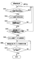
- FIG. 2 is a flowchart showing an unlock process executed by the BCM microcomputer.
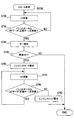
- FIG. 3 is a flowchart showing unlock processing executed by the microcomputer of the bullet key.
- FIG. 4 is a flowchart showing unlock processing executed by the regular key microcomputer.
- FIG. 5 is a flowchart showing distance setting processing executed by the microcomputer of the bullet key.
- FIG. 6 is a flowchart showing the distance setting process executed by the restaurant RFT [2].
- FIG. 7 is a flowchart showing the distance setting process executed by the RFT [3] of the parking lot.
- FIG. 8 is a ladder chart showing an example of unlock processing and distance setting processing.
- FIG. 9 is a flowchart showing a start process executed by the BCM microcomputer.
- FIG. 10 is a flowchart showing a start process executed by the regular key microcomputer.
- FIG. 11 is a flowchart showing a start process executed by the microcomputer of the bullet key.
- FIG. 12 is a ladder chart showing an example of the start process.
- the regular key 40a which is a portable device possessed by the user
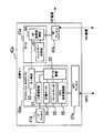
- a BCM (Body Control Module) 10 mounted on the vehicle communicate with each other to perform authentication. It is a system that enables In particular, the vehicle control system 1 of the present embodiment is configured so that authentication can be performed using the regular key 40a and the bullet key 40b that can communicate with the BCM 10.
- the vehicle control system 1 includes a BCM 10, a regular key 40 a, a bullet key 40 b, and a plurality of RFT (Radio Frequency Transceiver) 30, 70, and 80. Yes.
- the BCM 10 is mounted on a vehicle such as a passenger car, and performs authentication with the regular key 40a and the bullet key 40b. If this authentication is successful, for example, a vehicle drive device (engine control device, etc .: not shown), etc. Send an operation permission signal to. That is, the regular key 40a and the bullet key 40b function as wireless keys (portable devices) in the vehicle, and the BCM 10 functions as an authentication device.
- a vehicle drive device engine control device, etc .: not shown
- the RFT [1] 30 among the plurality of RFTs 30, 70, 80 is provided for the BCM 10.
- the RFT [2] 70 is arranged in an arbitrary building such as a restaurant, and the RFT [3] 80 is arranged in a parking lot corresponding to the building.
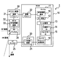
- the BCM 10 is configured as a computer (microcomputer 11) including a CPU, a memory (not shown), and the like.
- the BCM 10 performs functions as a key collation 12, a key ID management 13, an RF transmission / reception request 16, and a wake challenge transmission request 18. Further, the BCM 10 records a regular key ID 14 and a bullet key ID 15.
- the function as the key collation 12 collates the key ID that it has with the key ID obtained by LF communication or RF communication, and determines whether these IDs match. When these IDs match, unlocking of the door and driving of the vehicle are permitted.
- the regular key ID 14 and the bullet key ID 15 are read according to the processing executed by the function of the key collation 12.
- the function as the RF transmission / reception request 16 manages the operation as an interface for managing the transmission / reception of data to be subjected to RF (radio frequency) communication. Specifically, information transmitted from the regular key 40a and the bullet key 40b is received.
- the BCM 10 includes an LFIC 20 that is a circuit for performing LF communication, and a communication driver 22 that performs communication with the RFT 30.
- the LFIC 20 is disposed between the LF antenna 25 and the microcomputer 11 and transmits data instructed by the microcomputer 11 to be transmitted by LF communication and transmits data received through the LF antenna 25 to the microcomputer 11. (Immobility transmission / reception control 21).
- the RFT 30 includes a communication driver 31, an RFIC 32, and an RF antenna 34.
- the communication driver 31 communicates with a communication driver of another device such as the BCM 10.
- the RFIC 32 has a function as an RF transmission / reception control 33 that transmits and receives data by RF communication via the RF antenna 34.
- the regular key 40a includes an LF antenna 41a, an RF antenna 42a, an RFIC 43a, a microcomputer 50a, and an NFC (Near Field Communication) antenna 57a.
- the RFIC 43 has a function as an RF transmission / reception control 44 and a function as a bullet key ID determination 45.
- bullet key ID determination 45 it is determined whether or not the bullet key ID received via the RF antenna 42a is registered as the bullet key ID 55 described later using the function of the key collation 52 described later. I do.
- the microcomputer 50 a includes a CPU (not shown) and a memory (not shown), and functions as an LF reception control 51, a key verification 52, a key ID management 53, and an NFC transmission / reception control 56. Note that the microcomputer 50a may be configured by hardware such as an IC.
- control is performed to extract data from the LF signal received via the LF antenna 41a.
- NFC transmission / reception control 56 data is transmitted / received by NFC communication via the NFC antenna 57a.
- the functions as the key verification 52 and the key ID management 53 are the same as the functions of the key verification 12 and the key ID management 13 in the BCM 10.
- the microcomputer 50a includes a recording area (regular key ID 54, bullet key ID 55) for recording a regular key ID and a bullet key ID.
- a recording area for recording a regular key ID and a bullet key ID.
- the regular key ID and the bullet key ID are read from and written to the recording areas of the regular key ID 54 and the bullet key ID 55.
- the bullet key 40b includes an LF antenna 41b, an RF antenna 42b, an RFIC 43b, a microcomputer 50b, and an NFC (Near Field Communication) antenna 57b.
- the microcomputer 50b functions as an LF reception control 51, a key ID management 53, and an NFC transmission / reception control 56, and includes a recording area for the bullet key ID (valet key ID 55). These functions and recording areas are the same as the configuration of the regular key 40a in the microcomputer 50a.
- the RFIC 43b has a function as an RF sensitivity setting 46 and an RF output setting 47 in addition to the function as the RF transmission / reception control 44 described above.
- the reception sensitivity and output corresponding to this communication distance are set so that communication can be performed by the communication distance by RF communication set according to the external command.
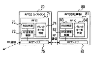
- the RFT [2] 70 includes an RFIC 71 and an RF antenna 75.
- the RFIC 71 has respective functions as an RF transmission / reception control 72, an RSSI (Received Signal Strength: Received Signal Strength) Indicator 73, and a bullet key ID determination 74.
- the intensity of the signal received via the RF antenna 75 is detected, and the output and sensitivity according to the intensity of the signal are set.
- the bullet key ID determination 74 it is determined whether or not the ID of the bullet key 40b received via the RF antenna 75 matches a preset one.
- the RFT [3] 80 includes an RFIC 81 and an RF antenna 85.
- the RFIC 81 has functions as an RF transmission / reception control 82, an RSSI determination 83, and a bullet key ID determination 84 similar to the RF transmission / reception control 72, RSSI determination 73, and bullet key ID determination 74 of RFT [2] 70.
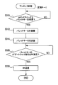
- the unlocking process is a process for unlocking the vehicle on which the BCM 10 is mounted, and is performed by the BCM 10, the regular key 40a, and the bullet key 40b communicating with each other.
- FIG. 2 shows an unlocking process by the BCM 10, and this process is started when a vehicle door switch (unlock switch) is operated, for example.
- an LF request signal requesting to return an ID is transmitted to the regular key 40a or the bullet key 40b located within the range of LF communication (S110). . Then, it is determined whether or not RF communication data including the ID of the normal key 40a is received from the normal key 40a or the bullet key 40b (S120).
- the unlock process by the bullet key 40b is a process that is started when NFC communication is established with the regular key 40a, for example.
- pairing is performed by NFC, and the ID of the bullet key 40b is transmitted to the regular key 40a (S210). Subsequently, it is determined whether an LF request signal has been received from the BCM 10 (S220).
- the process proceeds to S240 described later. If an LF request signal has been received (S220: YES), the received LF request signal is converted into an RF signal and transmitted as an LF gateway signal (S230). That is, the bullet key 40b functions as a gateway for relaying data.
- the RF reply signal is transmitted as an RF signal (S250). Also in this process, the bullet key 40b functions as a gateway. In the processing of S230 and S250, the ID of the bullet key is added and the data is transferred.
- data to be relayed may be encrypted.
- the data is transmitted by simply adding the ID of the bullet key without performing processing such as decryption on the data.
- the set time indicates the time for which the bullet key 40b is valid with respect to the regular key 40a. That is, after performing NFC communication with the regular key 40a, the bullet key 40b can be used only within the set time range.
- the received ID of the bullet key 40b is recorded in the area of the bullet key ID 55 (S312), and the ID of the bullet key 40b is transmitted to the BCM 10 (S314).
- the BCM 10 records this ID in the area of the bullet key 15 as an accessible key.
- the RF reply signal includes data obtained by encrypting its own ID (ID of the regular key 40a).
- the bullet key 40b of this embodiment has a distance setting function for setting a communicable distance with the regular key 40a.
- the bullet key 40b communicates with the facility-side RFT (RFT [2] 70 at the restaurant and RFT [3] at the parking lot) so that the optimum communicable distance according to the facility can be set. ing.
- This process is a process that is started at an arbitrary timing such as when the NFC communication with the regular key 40a is completed.
- the distance setting process is not an indispensable configuration, and a prescribed value (a preset value) can be used as the communicable distance.
- an area adjustment request is transmitted by RF communication (S410). Then, it is determined whether or not a reception success notification has been received from the RFT [2] 70 of the restaurant (S420).
- reception success notification has not been received (S420: NO)
- the process returns to S410. If a reception success notification has been received (S420: YES), it is determined whether or not various setting values (distance correction value and polling cycle) have been received from the RFT [2] 70 of the restaurant via RF communication (S430). ). If various setting values have not been received (S430: NO), the process of S430 is repeated.
- distance setting processing by the restaurant RFT [2] 70 will be described with reference to FIG. This process is started when, for example, the RFT [2] 70 of the restaurant is turned on, and then repeatedly executed.
- an area adjustment RF signal is transmitted (S520).
- the area adjustment RF signal is a signal for setting an optimum communicable distance according to the distance between the restaurant RFT [2] 70 and the parking lot RFT [3] 80.
- distance correction is performed from the signal strength (RSSI) and distance data (distance conversion value and area adjustment signal) (S550). That is, in order to make the distance range up to RFT [3] 80 of the parking lot a communicable range, this distance is corrected according to the acquired distance data. Then, the distance correction value and the polling cycle are transmitted by RF communication (S560).
- RSSI signal strength
- distance data distance conversion value and area adjustment signal
- a signal including the distance converted value and the area adjustment signal is transmitted by RF communication (S630). Then, it is determined whether a reception success signal has been received from the RFT [2] 70 of the restaurant (S640). If the reception success signal has not been received (S640: NO), the process returns to S610.
- reception success signal has been received (S640: YES)
- the distance setting process by the RFT [3] 80 in the parking lot is terminated.
- the bullet key 40b communicates with the restaurant RFT [2] to set the output and sensitivity according to the size of the area where the bullet key 40b is allowed to be used (see FIG. 8B). .
- the output of the bullet key 40b and the sensitivity setting are also notified to the BCM 10.
- the BCM 10 communicates with the bullet key 40b, but the bullet key 40b also communicates with the regular key 40a and authenticates with the BCM 10 using the ID of the regular key 40a ( (See FIG. 8C).
- start process which is a process when starting a vehicle (engine start or the like) in a vehicle on which the BCM 10 is mounted, will be described.
- the start process is performed in cooperation with the BCM 10, the regular key 40a, and the bullet key 40b.
- FIGS. 9 to 11 an example of starting the engine will be described as an example of starting the vehicle.
- This process is a process that is started when the user operates a start switch for starting the vehicle.
- an LF request signal requesting to return an ID is transmitted to the regular key 40a or the bullet key 40b located within the range of LF communication (S720). Then, it is determined whether or not RF communication data including the ID of the regular key 40a is received from the regular key 40a or the bullet key 40b (S730).
- the process returns to S720. If the RF communication data is received (S730: YES), the ID included in the RF communication data is collated (S740), and whether or not it matches the ID registered as the regular key ID 14 or the bullet key 15 or not. Is determined (S750).
- an LF request signal for requesting to return an ID is transmitted to the regular key 40a or the bullet key 40b located within the range of LF communication (S770). This process is suspended for a specified time (for example, about 1 minute) after the previous transmission of the LF request signal.
- This process is started when the power of the regular key 40a is turned on, for example, and is repeatedly executed thereafter.
- the start process by the bullet key 40b is a process that is started when NFC communication is established with the regular key 40a, for example.
- the process of S210 in FIG. 3 is omitted, but the same process may be performed at the beginning (before the process of S910).
- the RF reply signal is transmitted as an RF signal (S940).
- the start processing by the bullet key 40b is finished.
- a configuration that limits the usage time after NFC communication (the process of S260) may be employed.
- the BCM 10 communicates with the bullet key 40b, but the bullet key 40b also communicates with the regular key 40a and authenticates with the BCM 10 using the ID of the regular key 40a (FIG. 12 (A)).
- an ID request (RF communication continuation request) is periodically issued from the bullet key 40b from the BCM 10 to authenticate the ID (see FIG. 12B). At this time, if the ID authentication fails (including the case where the ID is not returned), the vehicle is stopped.
- the microcomputer 50b performs wireless communication with the regular key 40a when performing authentication with the BCM 10, and the microcomputer 50b performs authentication with the BCM 10 when wireless communication with the regular key 40a is established. carry out.
- the bullet key 40b of the present disclosure can be used as an apparatus for performing authentication with the BCM 10 only within a communicable range with the regular key 40a. Therefore, when this bullet key 40b is owned by a person other than the owner of the vehicle, it is possible to limit the area in which the vehicle can be controlled.
- the microcomputer 50b of the bullet key 40b acquires the authentication information necessary for authentication with the BCM 10 from the normal key 40a by performing wireless communication with the normal key 40a, and acquires the authentication information from the normal key 40a. Authentication with the BCM 10 is performed using the authentication information.
- Such a vehicle control system 1 can function as a relay device (gateway) that relays authentication information from the regular key 40a to the BCM 10. Therefore, it is not necessary for the bullet key 40b to exchange authentication information directly with the BCM 10, so that the process (preparation) when starting communication with the BCM 10 can be simplified. Further, even if the authentication information is encrypted, the encrypted authentication information can be relayed as it is, so there is no need to perform decryption in the bullet key 40b, and the bullet can be maintained while maintaining security.
- the configuration of the key 40b can be simplified.
- the microcomputer 50b of the bullet key 40b provides communication information for communicating with the regular key 40a using NFC communication that enables communication by bringing the bullet key 40b and the regular key 40a close to each other. Exchange.
- the microcomputer 50b of the bullet key 40b uses LF communication to acquire a start signal to start authentication with the BCM 10, and when receiving the start signal, uses RF communication different from LF communication. Wireless communication with the regular key 40a.
- the communication method since the communication method is changed, a communication distance suitable for the communication method can be easily ensured. Moreover, according to the vehicle control system 1, the communication technique currently used in the vehicle can be adopted as it is.
- the microcomputer 50b of the bullet key 40b transmits a start signal to the regular key 40a.
- Such a vehicle control system 1 can function as a relay device that relays the start signal to the regular key 40a. Therefore, information (authentication information) corresponding to the start signal can be acquired from the regular key 40a.
- the microcomputer 11 of the BCM 10 monitors the communication state with the bullet key 40b, and prohibits the continuation of vehicle control when the communication with the bullet key 40b is cut off.
- the present disclosure is applied to the process of unlocking the door and the process of starting the vehicle, but the present disclosure can be applied to any process in vehicle control.
- each process has been described as a process performed by software executed by a microcomputer.
- the process may be realized by hardware such as a circuit capable of performing an equivalent process.
- the BCM 10 in the above embodiment corresponds to a vehicle control device in the present disclosure
- the regular key 40a in the above embodiment corresponds to a portable device in the present disclosure
- the bullet key 40b in the above embodiment corresponds to a communication device in the present disclosure.
- the NFC communication in the above embodiment corresponds to the first communication method referred to in the present disclosure
- the LF communication in the above embodiment corresponds to the second communication method referred to in the present disclosure
- the RF communication corresponds to the third communication method in the present disclosure.
- the processes in S230 and S920 correspond to the portable device communication apparatus in the present disclosure
- the processes in S250 and S940 in the above embodiment correspond to the authentication apparatus in the present disclosure. .
- process of S210 in the above embodiment corresponds to a communication information exchange apparatus in the present disclosure
- process of S220 in the above embodiment corresponds to a start signal acquisition apparatus in the present disclosure
- processes in S770 and S780 in the above embodiment correspond to the communication monitoring device in the present disclosure
- the process in S790 in the above embodiment corresponds to the control prohibition device in the present disclosure.
- each section is expressed as S110, for example.
- each section can be divided into a plurality of subsections, while a plurality of sections can be combined into one section.
- each section configured in this manner can be referred to as a device, module, or means.
Abstract
A communication apparatus (40b) configured so as to be able to communicate with both a vehicle control device (10) for performing a preset vehicle control in a vehicle upon successful authentication with an authentication device in the possession of a user, and a portable device (40a) that functions as the authentication device, is provided with: a portable-device-facing communication device (S230, S920) for wirelessly communicating with the portable device when the communication apparatus is functioning as the authentication device, and performing authentication with the vehicle control device; and an authentication device (S250, S940) for performing authentication with the vehicle control device when wireless communication with the portable device has been established.
Description
本開示は、2014年2月10日に出願された日本出願番号2014-23600号に基づくもので、ここにその記載内容を援用する。
This disclosure is based on Japanese Patent Application No. 2014-23600 filed on February 10, 2014, and the description is incorporated herein.
本開示は、車両制御装置と通信可能な通信装置、車両制御装置、および車両制御システムに関する。
The present disclosure relates to a communication device capable of communicating with a vehicle control device, a vehicle control device, and a vehicle control system.
車両制御装置と通信可能な通信装置として、車両制御装置との認証の際に利用されるものが知られている(例えば、特許文献1参照)。この通信装置は、車両制御装置と通信により認証を行うことで車両制御装置の鍵として機能する。ただし、例えば車両のトランクを開ける機能を禁止する等、設定により機能に制限を加えることができるよう構成されている。
2. Description of the Related Art As a communication device that can communicate with a vehicle control device, a communication device that is used for authentication with the vehicle control device is known (for example, see Patent Document 1). This communication device functions as a key of the vehicle control device by performing authentication through communication with the vehicle control device. However, the function can be restricted by setting such as prohibiting the function of opening the trunk of the vehicle.
しかしながら、上記通信装置では、レストランやホテル等、車両の回送を従業員に依頼する状況において他人がこの通信装置を用いて車両を制御する場合、その従業員やその他の者によって車両が盗難に遭う虞があった。
However, in the above communication device, when another person uses the communication device to control the vehicle in a situation where the employee is requested to forward the vehicle, such as a restaurant or a hotel, the vehicle is stolen by the employee or others. There was a fear.
そこで、車両制御装置と通信可能な通信装置、車両制御装置、および車両制御システムにおいて、所有者以外の者に車両を運転させる際に、盗難を抑制できるようにすることを本開示の目的とする。
Accordingly, it is an object of the present disclosure to enable theft to be suppressed when a vehicle other than the owner is driven by a communication device, a vehicle control device, and a vehicle control system that can communicate with the vehicle control device. .
本開示の第一の態様において、使用者が所持する認証装置との認証が成功した場合に車両において予め設定された車両制御を実施する車両制御装置と、前記認証装置として機能する携帯機と、の両方に対して通信可能に構成された通信装置は、当該通信装置は前記認証装置として機能し、前記車両制御装置との認証を行う際に、前記携帯機との無線通信を行う対携帯機通信装置と、前記携帯機との無線通信が成立した場合に、前記車両制御装置との認証を実施する認証装置とを備える。
In the first aspect of the present disclosure, a vehicle control device that performs vehicle control preset in the vehicle when authentication with the authentication device possessed by the user is successful, a portable device that functions as the authentication device, The communication device configured to be communicable with both of the communication device functions as the authentication device, and performs wireless communication with the portable device when performing authentication with the vehicle control device. A communication device and an authentication device that performs authentication with the vehicle control device when wireless communication with the portable device is established.
このような通信装置によれば、通信装置を携帯機との通信可能範囲内だけで車両制御装置との認証を行うための装置として利用することができる。よって、この通信装置を車両の所有者以外が所持する場合、車両を制御可能な領域に制限を加えることができる。
According to such a communication device, the communication device can be used as a device for performing authentication with the vehicle control device only within a communicable range with the portable device. Therefore, when this communication apparatus is owned by a person other than the owner of the vehicle, it is possible to limit the area in which the vehicle can be controlled.
本開示の第二の態様において、使用者が所持する認証装置との認証が成功した場合に車両において予め設定された車両制御を実施する車両制御装置は、前記認証装置として第一の態様に記載の通信装置と通信可能に構成されている。
In the second aspect of the present disclosure, a vehicle control device that performs preset vehicle control in a vehicle when authentication with an authentication device possessed by a user is successful is described in the first aspect as the authentication device. The communication device is configured to be communicable.
上記の車両制御装置によれば、通信装置を携帯機との通信可能範囲内だけで車両制御装置との認証を行うための装置として利用することができる。よって、この通信装置を車両の所有者以外が所持する場合、車両を制御可能な領域に制限を加えることができる。
According to the above vehicle control device, the communication device can be used as a device for performing authentication with the vehicle control device only within a communicable range with the portable device. Therefore, when this communication apparatus is owned by a person other than the owner of the vehicle, it is possible to limit the area in which the vehicle can be controlled.
本開示の第三の態様において、車両制御システムは、使用者が所持する認証装置との認証が成功した場合に車両において予め設定された車両制御を実施する車両制御装置と、前記認証装置として機能する携帯機と、前記車両制御装置および前記携帯機の両方に対して通信可能に構成された通信装置と、を備える。前記通信装置は、第一の態様に記載の通信装置として構成されている。前記車両制御装置は、第二の態様に記載の車両制御装置として構成されている。
In the third aspect of the present disclosure, the vehicle control system functions as a vehicle control device that performs vehicle control preset in the vehicle when authentication with the authentication device possessed by the user is successful, and the authentication device. And a communication device configured to be communicable with both the vehicle control device and the portable device. The communication device is configured as the communication device described in the first aspect. The said vehicle control apparatus is comprised as a vehicle control apparatus as described in a 2nd aspect.
上記のシステムによれば、通信装置を携帯機との通信可能範囲内だけで車両制御装置との認証を行うための装置として利用することができる。よって、この通信装置を車両の所有者以外が所持する場合、車両を制御可能な領域に制限を加えることができる。
According to the above system, the communication device can be used as a device for performing authentication with the vehicle control device only within a communicable range with the portable device. Therefore, when this communication apparatus is owned by a person other than the owner of the vehicle, it is possible to limit the area in which the vehicle can be controlled.
本開示についての上記目的およびその他の目的、特徴や利点は、添付の図面を参照しながら下記の詳細な記述により、より明確になる。その図面は、
図1Aは、本開示が適用された車両制御システムの概略構成を示すブロック図であり、
図1Bは、正規キーの概略構成を示すブロック図であり、
図1Cは、バレットキーの概略構成を示すブロック図であり、
図1Dは、RFT[1]およびBCMの概略構成を示すブロック図であり、
図1Eは、RFT[2]およびRFT[3]の概略構成を示すブロック図であり、
図2は、BCMのマイコンが実行するアンロック処理を示すフローチャートであり、
図3は、バレットキーのマイコンが実行するアンロック処理を示すフローチャートであり、
図4は、正規キーのマイコンが実行するアンロック処理を示すフローチャートであり、
図5は、バレットキーのマイコンが実行する距離設定処理を示すフローチャートであり、
図6は、レストランのRFT[2]が実行する距離設定処理を示すフローチャートであり、
図7は、駐車場のRFT[3]が実行する距離設定処理を示すフローチャートであり、
図8は、アンロック処理および距離設定処理の一例を示すラダーチャートであり、
図9は、BCMのマイコンが実行するスタート処理を示すフローチャートであり、
図10は、正規キーのマイコンが実行するスタート処理を示すフローチャートであり、
図11は、バレットキーのマイコンが実行するスタート処理を示すフローチャートであり、
図12は、スタート処理の一例を示すラダーチャートである。
The above and other objects, features and advantages of the present disclosure will become more apparent from the following detailed description with reference to the accompanying drawings. The drawing
FIG. 1A is a block diagram illustrating a schematic configuration of a vehicle control system to which the present disclosure is applied, FIG. 1B is a block diagram showing a schematic configuration of a regular key, FIG. 1C is a block diagram illustrating a schematic configuration of a bullet key. FIG. 1D is a block diagram showing a schematic configuration of RFT [1] and BCM; FIG. 1E is a block diagram showing a schematic configuration of RFT [2] and RFT [3]. FIG. 2 is a flowchart showing an unlock process executed by the BCM microcomputer. FIG. 3 is a flowchart showing unlock processing executed by the microcomputer of the bullet key. FIG. 4 is a flowchart showing unlock processing executed by the regular key microcomputer. FIG. 5 is a flowchart showing distance setting processing executed by the microcomputer of the bullet key. FIG. 6 is a flowchart showing the distance setting process executed by the restaurant RFT [2]. FIG. 7 is a flowchart showing the distance setting process executed by the RFT [3] of the parking lot. FIG. 8 is a ladder chart showing an example of unlock processing and distance setting processing. FIG. 9 is a flowchart showing a start process executed by the BCM microcomputer. FIG. 10 is a flowchart showing a start process executed by the regular key microcomputer. FIG. 11 is a flowchart showing a start process executed by the microcomputer of the bullet key. FIG. 12 is a ladder chart showing an example of the start process.
以下に本開示にかかる実施の形態を図面と共に説明する。
Embodiments according to the present disclosure will be described below with reference to the drawings.
[本実施形態の構成]
本開示が適用された車両制御システム1は、ユーザが所持する携帯機である正規キー40aと車両に搭載されたBCM(Body Control Module)10とが互いに通信し、認証を行うことで車両の制御を可能とするシステムである。特に、本実施形態の車両制御システム1では、正規キー40aおよびBCM10に対して通信可能なバレットキー40bを用いて認証を行うこともできるよう構成されている。 [Configuration of this embodiment]
In thevehicle control system 1 to which the present disclosure is applied, the regular key 40a, which is a portable device possessed by the user, and a BCM (Body Control Module) 10 mounted on the vehicle communicate with each other to perform authentication. It is a system that enables In particular, the vehicle control system 1 of the present embodiment is configured so that authentication can be performed using the regular key 40a and the bullet key 40b that can communicate with the BCM 10.
本開示が適用された車両制御システム1は、ユーザが所持する携帯機である正規キー40aと車両に搭載されたBCM(Body Control Module)10とが互いに通信し、認証を行うことで車両の制御を可能とするシステムである。特に、本実施形態の車両制御システム1では、正規キー40aおよびBCM10に対して通信可能なバレットキー40bを用いて認証を行うこともできるよう構成されている。 [Configuration of this embodiment]
In the
詳細には、車両制御システム1は、図1Aから図1Eに示すように、BCM10と、正規キー40aと、バレットキー40bと、複数のRFT(Radio Frequency Transceiver)30,70,80とを備えている。
Specifically, as shown in FIGS. 1A to 1E, the vehicle control system 1 includes a BCM 10, a regular key 40 a, a bullet key 40 b, and a plurality of RFT (Radio Frequency Transceiver) 30, 70, and 80. Yes.
BCM10は、乗用車等の車両に搭載されており、正規キー40aやバレットキー40bとの間で認証を実施し、この認証が成功すると、例えば車両の駆動装置(エンジン制御装置等:図示省略)等に作動許可信号を送る。つまり、正規キー40aやバレットキー40bは、車両における無線キー(携帯機)として機能し、BCM10はその認証装置として機能する。
The BCM 10 is mounted on a vehicle such as a passenger car, and performs authentication with the regular key 40a and the bullet key 40b. If this authentication is successful, for example, a vehicle drive device (engine control device, etc .: not shown), etc. Send an operation permission signal to. That is, the regular key 40a and the bullet key 40b function as wireless keys (portable devices) in the vehicle, and the BCM 10 functions as an authentication device.
また、複数のRFT30,70,80のうちのRFT[1]30は、BCM10に対して備えられている。また、RFT[2]70は、レストラン等の任意の建物に配置されており、RFT[3]80は、建物に対応する駐車場に配置されている。
Also, the RFT [1] 30 among the plurality of RFTs 30, 70, 80 is provided for the BCM 10. The RFT [2] 70 is arranged in an arbitrary building such as a restaurant, and the RFT [3] 80 is arranged in a parking lot corresponding to the building.
BCM10は、CPU、メモリ(図示省略)等を備えたコンピュータ(マイコン11)として構成されている。BCM10は、キー照合12、キーID管理13、RF送受信要求16、ウェイクチャレンジ送信要求18、としての機能を実行する。また、BCM10は、正規キーID14、バレットキーID15を記録している。
The BCM 10 is configured as a computer (microcomputer 11) including a CPU, a memory (not shown), and the like. The BCM 10 performs functions as a key collation 12, a key ID management 13, an RF transmission / reception request 16, and a wake challenge transmission request 18. Further, the BCM 10 records a regular key ID 14 and a bullet key ID 15.
キー照合12としての機能では、自身が有するキーIDと、LF通信またはRF通信で得られたキーIDとを照合し、これらのIDが一致するか否かを判定する。そして、これらのID一致する場合にドアのアンロックや車両の駆動を許可する。
The function as the key collation 12 collates the key ID that it has with the key ID obtained by LF communication or RF communication, and determines whether these IDs match. When these IDs match, unlocking of the door and driving of the vehicle are permitted.
キーID管理13としての機能では、キー照合12の機能で実行される処理に従って、正規キーID14やバレットキーID15の読み出し等を行う。
In the function as the key ID management 13, the regular key ID 14 and the bullet key ID 15 are read according to the processing executed by the function of the key collation 12.
RF送受信要求16としての機能では、RF(radio frequency)通信を行うべきデータの送受信を管理するインタフェースとしての作動を管理する。具体的には、正規キー40aやバレットキー40bから送信される情報を受信する。
The function as the RF transmission / reception request 16 manages the operation as an interface for managing the transmission / reception of data to be subjected to RF (radio frequency) communication. Specifically, information transmitted from the regular key 40a and the bullet key 40b is received.
ウェイクチャレンジ送信要求18としての機能では、車両のドア横に設けられたドアスイッチ(図示省略)やスタートスイッチ(図示省略)が操作されたときに、正規キー40aやバレットキー40bに送信するLF信号を生成する。
In the function as the wake challenge transmission request 18, an LF signal to be transmitted to the regular key 40a or the bullet key 40b when a door switch (not shown) or a start switch (not shown) provided on the side of the vehicle door is operated. Is generated.
なお、BCM10には、LF通信を行うための回路であるLFIC20と、RFT30との通信を行う通信ドライバ22とを備えている。LFIC20は、LFアンテナ25とマイコン11との間に配置され、マイコン11によりLF通信で送信するよう指示されたデータの送信を行うとともに、LFアンテナ25を介して受信したデータをマイコン11に送る機能(イモビ送受信制御21)を備えている。
The BCM 10 includes an LFIC 20 that is a circuit for performing LF communication, and a communication driver 22 that performs communication with the RFT 30. The LFIC 20 is disposed between the LF antenna 25 and the microcomputer 11 and transmits data instructed by the microcomputer 11 to be transmitted by LF communication and transmits data received through the LF antenna 25 to the microcomputer 11. (Immobility transmission / reception control 21).
RFT30は、通信ドライバ31と、RFIC32と、RFアンテナ34とを備えている。通信ドライバ31は、BCM10等の他の装置の通信ドライバとの通信を行う。RFIC32は、RFアンテナ34を介してRF通信でデータの送受信を行うRF送受信制御33としての機能を備えている。
The RFT 30 includes a communication driver 31, an RFIC 32, and an RF antenna 34. The communication driver 31 communicates with a communication driver of another device such as the BCM 10. The RFIC 32 has a function as an RF transmission / reception control 33 that transmits and receives data by RF communication via the RF antenna 34.
正規キー40aは、LFアンテナ41aと、RFアンテナ42aと、RFIC43aと、マイコン50aと、NFC(Near Field Communication)アンテナ57aと、を備えている。RFIC43は、RF送受信制御44としての機能と、バレットキーID判定45としての機能とを備えている。
The regular key 40a includes an LF antenna 41a, an RF antenna 42a, an RFIC 43a, a microcomputer 50a, and an NFC (Near Field Communication) antenna 57a. The RFIC 43 has a function as an RF transmission / reception control 44 and a function as a bullet key ID determination 45.
RF送受信制御44としての機能では、マイコン50aからの指示に従ってRFアンテナ42aを介したデータの送受信を行う。
In the function as the RF transmission / reception control 44, data is transmitted / received via the RF antenna 42a in accordance with an instruction from the microcomputer 50a.
バレットキーID判定45としての機能では、後述するキー照合52の機能を用いて、RFアンテナ42aを介して受信したバレットキーIDが後述するバレットキーID55として登録されたものであるか否かの判定を行う。
In the function as the bullet key ID determination 45, it is determined whether or not the bullet key ID received via the RF antenna 42a is registered as the bullet key ID 55 described later using the function of the key collation 52 described later. I do.
マイコン50aは、CPU(図示省略)やメモリ(図示省略)を備えており、LF受信制御51、キー照合52、キーID管理53、NFC送受信制御56として機能を備えている。なお、マイコン50aは、IC等のハードウェアで構成されていてもよい。
The microcomputer 50 a includes a CPU (not shown) and a memory (not shown), and functions as an LF reception control 51, a key verification 52, a key ID management 53, and an NFC transmission / reception control 56. Note that the microcomputer 50a may be configured by hardware such as an IC.
LF受信制御51として機能では、LFアンテナ41aを介して受信したLF信号からデータを抽出する制御を行う。
In the function as the LF reception control 51, control is performed to extract data from the LF signal received via the LF antenna 41a.
NFC送受信制御56として機能では、NFCアンテナ57aを介してNFC通信によりデータの送受信を行う。
In the function as the NFC transmission / reception control 56, data is transmitted / received by NFC communication via the NFC antenna 57a.
なお、キー照合52、キーID管理53として機能では、BCM10におけるキー照合12、キーID管理13の機能と同等である。
The functions as the key verification 52 and the key ID management 53 are the same as the functions of the key verification 12 and the key ID management 13 in the BCM 10.
また、マイコン50aは、正規キーIDやバレットキーIDを記録するための記録領域(正規キーID54、バレットキーID55)を備えている。キーID管理53の機能では、正規キーID54、バレットキーID55の記録領域に対して正規キーIDやバレットキーIDの読み書きを行うことになる。
Further, the microcomputer 50a includes a recording area (regular key ID 54, bullet key ID 55) for recording a regular key ID and a bullet key ID. In the function of the key ID management 53, the regular key ID and the bullet key ID are read from and written to the recording areas of the regular key ID 54 and the bullet key ID 55.
バレットキー40bは、LFアンテナ41bと、RFアンテナ42bと、RFIC43bと、マイコン50bと、NFC(Near Field Communication)アンテナ57bと、を備えている。
The bullet key 40b includes an LF antenna 41b, an RF antenna 42b, an RFIC 43b, a microcomputer 50b, and an NFC (Near Field Communication) antenna 57b.
マイコン50bは、LF受信制御51、キーID管理53、NFC送受信制御56として機能を備え、バレットキーIDの記録領域(バレットキーID55)を備えている。これらの機能および記録領域は、正規キー40aのマイコン50aにおける構成と同様である。
The microcomputer 50b functions as an LF reception control 51, a key ID management 53, and an NFC transmission / reception control 56, and includes a recording area for the bullet key ID (valet key ID 55). These functions and recording areas are the same as the configuration of the regular key 40a in the microcomputer 50a.
RFIC43bは、前述のRF送受信制御44としての機能に加え、RF感度設定46、RF出力設定47しての機能とを備えている。
The RFIC 43b has a function as an RF sensitivity setting 46 and an RF output setting 47 in addition to the function as the RF transmission / reception control 44 described above.
RF感度設定46やRF出力設定47しての機能では、外部指令に従って設定されるRF通信による通信距離で通信ができるように、この通信距離に応じた受信感度や出力を設定する。
In the function of the RF sensitivity setting 46 and the RF output setting 47, the reception sensitivity and output corresponding to this communication distance are set so that communication can be performed by the communication distance by RF communication set according to the external command.
RFT[2]70は、RFIC71と、RFアンテナ75とを備えている。RFIC71は、RF送受信制御72、RSSI(受信信号強度:Received Signal Strength Indicator)判定73、バレットキーID判定74としてのそれぞれの機能を備えている。
The RFT [2] 70 includes an RFIC 71 and an RF antenna 75. The RFIC 71 has respective functions as an RF transmission / reception control 72, an RSSI (Received Signal Strength: Received Signal Strength) Indicator 73, and a bullet key ID determination 74.
RF送受信制御72としての機能では、RFアンテナ75を介したデータの送受信を制御する。
In the function as the RF transmission / reception control 72, transmission / reception of data via the RF antenna 75 is controlled.
RSSI判定73としての機能では、RFアンテナ75を介して受信された信号の強度を検出し、信号の強度に応じた出力および感度を設定する。
In the function as the RSSI determination 73, the intensity of the signal received via the RF antenna 75 is detected, and the output and sensitivity according to the intensity of the signal are set.
バレットキーID判定74としての機能では、RFアンテナ75を介して受信されたバレットキー40bのIDが予め設定されたものと一致するか否かを判定する。
In the function as the bullet key ID determination 74, it is determined whether or not the ID of the bullet key 40b received via the RF antenna 75 matches a preset one.
RFT[3]80は、RFIC81と、RFアンテナ85とを備えている。RFIC81は、RFT[2]70のRF送受信制御72、RSSI判定73、バレットキーID判定74と同様の、RF送受信制御82、RSSI判定83、バレットキーID判定84としての機能を備えている。
The RFT [3] 80 includes an RFIC 81 and an RF antenna 85. The RFIC 81 has functions as an RF transmission / reception control 82, an RSSI determination 83, and a bullet key ID determination 84 similar to the RF transmission / reception control 72, RSSI determination 73, and bullet key ID determination 74 of RFT [2] 70.
[本実施形態の処理]
このように構成された車両制御システム1においては、図2以下に示すアンロック処理を実施する。アンロック処理は、BCM10が搭載された車両の開錠を行う際の処理であり、BCM10、正規キー40a、バレットキー40bが互いに通信を行うことで実施される。 [Process of this embodiment]
In thevehicle control system 1 configured as described above, unlock processing shown in FIG. The unlocking process is a process for unlocking the vehicle on which the BCM 10 is mounted, and is performed by the BCM 10, the regular key 40a, and the bullet key 40b communicating with each other.
このように構成された車両制御システム1においては、図2以下に示すアンロック処理を実施する。アンロック処理は、BCM10が搭載された車両の開錠を行う際の処理であり、BCM10、正規キー40a、バレットキー40bが互いに通信を行うことで実施される。 [Process of this embodiment]
In the
ここで、図2は、BCM10によるアンロック処理を示し、この処理は、例えば車両のドアスイッチ(アンロックスイッチ)が操作されると開始される。
Here, FIG. 2 shows an unlocking process by the BCM 10, and this process is started when a vehicle door switch (unlock switch) is operated, for example.
BCM10によるアンロック処理では、図2に示すように、まず、LF通信の範囲内に位置する正規キー40aまたはバレットキー40bに対して、IDを返すよう要求するLF要求信号を送信する(S110)。そして、正規キー40aまたはバレットキー40bから正規キー40aのIDを含むRF通信データを受信したか否かを判定する(S120)。
In the unlock process by the BCM 10, as shown in FIG. 2, first, an LF request signal requesting to return an ID is transmitted to the regular key 40a or the bullet key 40b located within the range of LF communication (S110). . Then, it is determined whether or not RF communication data including the ID of the normal key 40a is received from the normal key 40a or the bullet key 40b (S120).
RF通信データを受信してなければ(S120:NO)、S110の処理に戻る。また、RF通信データを受信していれば(S120:YES)、RF通信データに含まれるIDの照合を行い(S130)、正規キーID14として登録されたIDと一致するか否かを判定する(S140)。
If no RF communication data has been received (S120: NO), the process returns to S110. If the RF communication data is received (S120: YES), the ID included in the RF communication data is collated (S130), and it is determined whether or not the ID is registered as the regular key ID 14 ( S140).
なお、利用可能なバレットキーIDが、後述する処理においてバレットキーID15の記録領域に予め登録されており、バレットキー40bからRF通信データを受信した場合、このIDと一致するかについても判定する。
It should be noted that when the available bullet key ID is registered in advance in the recording area of the bullet key ID 15 in the process described later and RF communication data is received from the bullet key 40b, it is also determined whether or not it matches this ID.
IDが一致すれば(S140:YES)、ドアをアンロックするためのアクチュエータ(図示省略)を作動させ(S150)、BCM10によるアンロック処理を終了する。また、IDが一致しなければ(S140:NO)、BCM10によるアンロック処理を終了する。
If the IDs match (S140: YES), an actuator (not shown) for unlocking the door is activated (S150), and the unlocking process by the BCM 10 is terminated. If the IDs do not match (S140: NO), the unlock process by the BCM 10 is terminated.
次に、バレットキー40bによるアンロック処理について図3を用いて説明する。バレットキー40bによるアンロック処理は、例えば、正規キー40aとNFC通信が成立すると開始される処理である。
Next, unlock processing by the bullet key 40b will be described with reference to FIG. The unlock process by the bullet key 40b is a process that is started when NFC communication is established with the regular key 40a, for example.
詳細には、図3に示すように、まず、NFCによるペアリングを行い、バレットキー40bのIDを正規キー40aに送信する(S210)。続いて、BCM10からLF要求信号を受信したか否かを判定する(S220)。
Specifically, as shown in FIG. 3, first, pairing is performed by NFC, and the ID of the bullet key 40b is transmitted to the regular key 40a (S210). Subsequently, it is determined whether an LF request signal has been received from the BCM 10 (S220).
LF要求信号を受信していなければ(S220:NO)、後述するS240の処理に移行する。また、LF要求信号を受信していれば(S220:YES)、受信したLF要求信号をRF信号に変換してLFゲートウェイ信号として送信する(S230)。すなわち、バレットキー40bはデータを中継するゲートウェイとして機能する。
If the LF request signal has not been received (S220: NO), the process proceeds to S240 described later. If an LF request signal has been received (S220: YES), the received LF request signal is converted into an RF signal and transmitted as an LF gateway signal (S230). That is, the bullet key 40b functions as a gateway for relaying data.
続いて、正規キー40aからRF返信信号を受信したか否かを判定する(S240)。RF返信信号を受信していなければ(S240:NO)、後述するS260の処理に移行する。
Subsequently, it is determined whether or not an RF reply signal is received from the regular key 40a (S240). If the RF reply signal is not received (S240: NO), the process proceeds to S260 described later.
また、RF返信信号を受信していれば(S240:YES)、RF返信信号をRF信号で送信する(S250)。この処理においても、バレットキー40bはゲートウェイとして機能する。なお、S230およびS250の処理においては、バレットキーのIDを付加してデータを転送する。
If an RF reply signal is received (S240: YES), the RF reply signal is transmitted as an RF signal (S250). Also in this process, the bullet key 40b functions as a gateway. In the processing of S230 and S250, the ID of the bullet key is added and the data is transferred.
特に、上記のようにバレットキー40bがゲートウェイとして機能する際に、中継するデータは暗号化されていてもよい。暗号化されたデータを中継する際には、データに対して復号等の処理を行うことなく、バレットキーのIDを付加するだけでデータを送信する。
In particular, when the bullet key 40b functions as a gateway as described above, data to be relayed may be encrypted. When relaying the encrypted data, the data is transmitted by simply adding the ID of the bullet key without performing processing such as decryption on the data.
続いて、予め設定された設定時間が経過したか否かを判定する(S260)。ここでの設定時間は、正規キー40aに対してバレットキー40bを有効とする時間を示す。つまり、正規キー40aとNFC通信を行ってから、設定時間の範囲内だけバレットキー40bを利用できる状態となる。
Subsequently, it is determined whether or not a preset time has elapsed (S260). The set time here indicates the time for which the bullet key 40b is valid with respect to the regular key 40a. That is, after performing NFC communication with the regular key 40a, the bullet key 40b can be used only within the set time range.
設定時間が経過していなければ(S260:NO)、S220の処理に戻る。また、設定時間が経過していれば(S260:YES)、バレットキー40bによるアンロック処理を終了する。
If the set time has not elapsed (S260: NO), the process returns to S220. If the set time has elapsed (S260: YES), the unlocking process using the bullet key 40b is terminated.
次に、正規キー40aによるアンロック処理について図4を用いて説明する。この処理は、例えば、正規キー40aの電源が投入されると開始され、その後、繰り返し実施される処理である。
Next, the unlocking process using the regular key 40a will be described with reference to FIG. This process is started when the power of the regular key 40a is turned on, for example, and is repeatedly executed thereafter.
正規キー40aによるアンロック処理では、図4に示すように、まず、NFC通信を利用してバレットキー40bのIDを受信したか否かを判定する(S310)。IDを受信していなければ(S310:NO)、S310の処理を繰り返す。
In the unlocking process using the regular key 40a, as shown in FIG. 4, it is first determined whether or not the ID of the bullet key 40b has been received using NFC communication (S310). If the ID is not received (S310: NO), the process of S310 is repeated.
また、IDを受信していれば(S310:YES)、受信したバレットキー40bのIDをバレットキーID55の領域に記録し(S312)、バレットキー40bのIDをBCM10に対して送信する(S314)。なお、BCM10は、バレットキー40bのIDを受信すると、アクセス可能なキーとしてバレットキー15の領域にこのIDを記録させる。
If the ID is received (S310: YES), the received ID of the bullet key 40b is recorded in the area of the bullet key ID 55 (S312), and the ID of the bullet key 40b is transmitted to the BCM 10 (S314). . When receiving the ID of the bullet key 40b, the BCM 10 records this ID in the area of the bullet key 15 as an accessible key.
続いて、バレットキー40bからLFゲートウェイ信号をRF信号で受信したか否かを判定する(S320)。
Subsequently, it is determined whether or not the LF gateway signal is received as an RF signal from the bullet key 40b (S320).
LFゲートウェイ信号を受信していなければ(S320:NO)、S320の処理を繰り返す。また、LFゲートウェイ信号を受信していれば(S320:YES)、RF返信信号をRF通信で送信する(S330)。なお、RF返信信号には、自身のID(正規キー40aのID)を暗号化したデータを含む。
If the LF gateway signal has not been received (S320: NO), the process of S320 is repeated. If an LF gateway signal is received (S320: YES), an RF reply signal is transmitted by RF communication (S330). The RF reply signal includes data obtained by encrypting its own ID (ID of the regular key 40a).
このような処理が終了すると、正規キー40aによるアンロック処理を終了する。
When such processing is completed, the unlock processing using the regular key 40a is completed.
ところで、本実施形態のバレットキー40bにおいては、正規キー40aとの通信可能距離を設定する距離設定機能を備えている。この機能では、バレットキー40bが設備側のRFT(レストランのRFT[2]70および駐車場のRFT[3])と通信を行うことによって、設備に応じた最適な通信可能距離を設定できるようにしている。
By the way, the bullet key 40b of this embodiment has a distance setting function for setting a communicable distance with the regular key 40a. In this function, the bullet key 40b communicates with the facility-side RFT (RFT [2] 70 at the restaurant and RFT [3] at the parking lot) so that the optimum communicable distance according to the facility can be set. ing.
この機能は、図5以下に示す距離設定処理を各装置が実行することによって実現される。始めに、バレットキー40bによる距離設定処理について図5を用いて説明する。
This function is realized by each device executing the distance setting process shown in FIG. First, the distance setting process using the bullet key 40b will be described with reference to FIG.
この処理は、正規キー40aとのNFC通信が完了したとき等、任意のタイミングで開始される処理である。なお、距離設定処理については、必須の構成ではなく、通信可能距離は規定値(予め設定された値)を利用することもできる。
This process is a process that is started at an arbitrary timing such as when the NFC communication with the regular key 40a is completed. Note that the distance setting process is not an indispensable configuration, and a prescribed value (a preset value) can be used as the communicable distance.
バレットキー40bによる距離設定処理では、図5に示すように、まず、エリア調整要求をRF通信で送信する(S410)。そして、レストランのRFT[2]70から受信成功通知を受けたか否かを判定する(S420)。
In the distance setting process using the bullet key 40b, as shown in FIG. 5, first, an area adjustment request is transmitted by RF communication (S410). Then, it is determined whether or not a reception success notification has been received from the RFT [2] 70 of the restaurant (S420).
受信成功通知を受けていなければ(S420:NO)、S410の処理に戻る。また、受信成功通知を受けていれば(S420:YES)、レストランのRFT[2]70から、各種設定値(距離補正値およびポーリング周期)をRF通信で受信したか否かを判定する(S430)。各種設定値を受信していなければ(S430:NO)、S430の処理を繰り返す。
If the reception success notification has not been received (S420: NO), the process returns to S410. If a reception success notification has been received (S420: YES), it is determined whether or not various setting values (distance correction value and polling cycle) have been received from the RFT [2] 70 of the restaurant via RF communication (S430). ). If various setting values have not been received (S430: NO), the process of S430 is repeated.
また、各種設定値を受信していれば(S430:YES)、この設定値に従って、RF通信の感度とRF通信の出力とを補正する(S440)。そして、完了通知を送信し(S450)、バレットキー40bによる距離設定処理を終了する。
If various set values have been received (S430: YES), the sensitivity of RF communication and the output of RF communication are corrected according to the set values (S440). Then, a completion notification is transmitted (S450), and the distance setting process using the bullet key 40b is terminated.
次に、レストランのRFT[2]70による距離設定処理について図6を用いて説明する。この処理は、例えばレストランのRFT[2]70の電源が投入されると開始され、その後、繰り返し実施される処理である。
Next, distance setting processing by the restaurant RFT [2] 70 will be described with reference to FIG. This process is started when, for example, the RFT [2] 70 of the restaurant is turned on, and then repeatedly executed.
RFT[2]70による距離設定処理では、図6に示すように、まず、バレットキー40bからエリア調整要求をRF通信で受信したか否かを判定する(S510)。エリア調整要求を受信していなければ(S510:NO)、S510の処理を繰り返す。
In the distance setting process by RFT [2] 70, as shown in FIG. 6, it is first determined whether or not an area adjustment request is received from the bullet key 40b by RF communication (S510). If the area adjustment request has not been received (S510: NO), the process of S510 is repeated.
また、エリア調整要求を受信していれば(S510:YES)、エリア調整RF信号を送信する(S520)。ここでエリア調整RF信号とは、レストランのRFT[2]70と駐車場のRFT[3]80との距離に応じて最適な通信可能距離を設定させるための信号である。
If an area adjustment request has been received (S510: YES), an area adjustment RF signal is transmitted (S520). Here, the area adjustment RF signal is a signal for setting an optimum communicable distance according to the distance between the restaurant RFT [2] 70 and the parking lot RFT [3] 80.
続いて、駐車場のRFT[3]80から受信成功通知を受信したか否かを判定する(S530)。受信成功通知を受信していなければ(S530:NO)、S510の処理に戻る。
Subsequently, it is determined whether or not a reception success notification has been received from the RFT [3] 80 of the parking lot (S530). If the reception success notification has not been received (S530: NO), the processing returns to S510.
また、受信成功通知を受信していれば(S530:YES)、駐車場のRFT[3]80から距離換算値とエリア調整に関する信号をRF通信で受信したか否かを判定する(S540)。この信号を受信していなければ(S540:NO)、S510の処理に戻る。
If a reception success notification has been received (S530: YES), it is determined whether or not a distance conversion value and a signal relating to area adjustment have been received from the RFT [3] 80 of the parking lot by RF communication (S540). If this signal has not been received (S540: NO), the process returns to S510.
また、この信号を受信していれば(S540:YES)、信号強度(RSSI)と距離データ(距離換算値とエリア調整に関する信号)とから距離補正を行う(S550)。すなわち、駐車場のRFT[3]80までの距離範囲を通信可能範囲とするために、この距離を取得した距離データに従って補正する。そして、距離補正値とポーリング周期とをRF通信で送信する(S560)。
If this signal is received (S540: YES), distance correction is performed from the signal strength (RSSI) and distance data (distance conversion value and area adjustment signal) (S550). That is, in order to make the distance range up to RFT [3] 80 of the parking lot a communicable range, this distance is corrected according to the acquired distance data. Then, the distance correction value and the polling cycle are transmitted by RF communication (S560).
続いて、バレットキー40bから完了通知を受けたか否かを判定する(S570)。受信成功通知を受けていなければ(S570:NO)、S560の処理に戻る。また、受信成功通知を受けていれば(S570:YES)、RFT[2]70による距離設定処理を終了する。
Subsequently, it is determined whether or not a completion notification is received from the bullet key 40b (S570). If the reception success notification has not been received (S570: NO), the process returns to S560. If the reception success notification has been received (S570: YES), the distance setting process by RFT [2] 70 is terminated.
次に、駐車場のRFT[3]80による距離設定処理について図7を用いて説明する。この処理は、例えば駐車場のRFT[3]80の電源が投入されると開始され、その後、繰り返し実施される処理である。
Next, distance setting processing by RFT [3] 80 in the parking lot will be described with reference to FIG. This process is started when the RFT [3] 80 of the parking lot is turned on, for example, and then repeatedly executed.
駐車場のRFT[3]80による距離設定処理では、図7に示すように、まず、レストランのRFT[2]70からエリア調整RF信号を受信したか否かを判定する(S610)。エリア調整RF信号を受信していなければ(S610:NO)、S610の処理を繰り返す。
In the distance setting process by the RFT [3] 80 in the parking lot, as shown in FIG. 7, it is first determined whether or not an area adjustment RF signal has been received from the RFT [2] 70 of the restaurant (S610). If the area adjustment RF signal is not received (S610: NO), the process of S610 is repeated.
また、エリア調整RF信号を受信していれば(S610:YES)、信号強度(RSSI)に基づいて距離換算を行う。すなわち、信号強度に基づいてレストランのRFT[2]70までの距離を算出する。
If an area adjustment RF signal is received (S610: YES), distance conversion is performed based on the signal strength (RSSI). That is, the distance to the restaurant RFT [2] 70 is calculated based on the signal strength.
続いて、距離換算値とエリア調整信号とを含む信号をRF通信で送信する(S630)。そして、レストランのRFT[2]70から受信成功信号を受信したか否かを判定する(S640)。受信成功信号を受信していなければ(S640:NO)、S610の処理に戻る。
Subsequently, a signal including the distance converted value and the area adjustment signal is transmitted by RF communication (S630). Then, it is determined whether a reception success signal has been received from the RFT [2] 70 of the restaurant (S640). If the reception success signal has not been received (S640: NO), the process returns to S610.
また、受信成功信号を受信していれば(S640:YES)、駐車場のRFT[3]80による距離設定処理を終了する。
If the reception success signal has been received (S640: YES), the distance setting process by the RFT [3] 80 in the parking lot is terminated.
このようなアンロック処理や距離設定処理におけるデータのやり取りの一例について、図8を用いて説明する。アンロック処理において正規キー40aとバレットキー40bとが近接させられると、各キー40a,40bはNFC通信でIDのやり取りを行い、正規キー40aはBCM10にバレットキー40bの登録をさせる(図8の(A)参照)。
An example of data exchange in such unlock processing and distance setting processing will be described with reference to FIG. When the regular key 40a and the bullet key 40b are brought close to each other in the unlock process, the keys 40a and 40b exchange IDs by NFC communication, and the regular key 40a causes the BCM 10 to register the bullet key 40b (FIG. 8). (See (A)).
そして、バレットキー40bは、レストランのRFT[2]と通信を行うことによって、バレットキー40bの使用を許可する領域の広さに応じた出力および感度を設定する(図8の(B)参照)。なお、バレットキー40bの出力および感度の設定はBCM10にも通知される。
The bullet key 40b communicates with the restaurant RFT [2] to set the output and sensitivity according to the size of the area where the bullet key 40b is allowed to be used (see FIG. 8B). . The output of the bullet key 40b and the sensitivity setting are also notified to the BCM 10.
ドアのアンロックを実施する際には、BCM10はバレットキー40bと通信を行うが、バレットキー40bは正規キー40aとも通信を行い、正規キー40aのIDを利用してBCM10との認証を行う(図8の(C)参照)。
When the door is unlocked, the BCM 10 communicates with the bullet key 40b, but the bullet key 40b also communicates with the regular key 40a and authenticates with the BCM 10 using the ID of the regular key 40a ( (See FIG. 8C).
次に、BCM10が搭載された車両において車両の始動(エンジンスタート等)を行う際の処理であるスタート処理について説明する。スタート処理は、BCM10と、正規キー40aと、バレットキー40bとが協働して行う。なお、図9~図11の説明においては、車両の始動の一例としてエンジンを始動する例について説明する。
Next, a start process, which is a process when starting a vehicle (engine start or the like) in a vehicle on which the BCM 10 is mounted, will be described. The start process is performed in cooperation with the BCM 10, the regular key 40a, and the bullet key 40b. In the description of FIGS. 9 to 11, an example of starting the engine will be described as an example of starting the vehicle.
始めに、BCM10によるスタート処理について図9を用いて説明する。この処理は、使用者によって車両を始動するためのスタートスイッチが操作されると開始される処理である。
First, the start process by the BCM 10 will be described with reference to FIG. This process is a process that is started when the user operates a start switch for starting the vehicle.
詳細には、図9に示すように、まず、LF通信の範囲内に位置する正規キー40aまたはバレットキー40bに対して、IDを返すよう要求するLF要求信号を送信する(S720)。そして、正規キー40aまたはバレットキー40bから正規キー40aのIDを含むRF通信データを受信したか否かを判定する(S730)。
Specifically, as shown in FIG. 9, first, an LF request signal requesting to return an ID is transmitted to the regular key 40a or the bullet key 40b located within the range of LF communication (S720). Then, it is determined whether or not RF communication data including the ID of the regular key 40a is received from the regular key 40a or the bullet key 40b (S730).
RF通信データを受信してなければ(S730:NO)、S720の処理に戻る。また、RF通信データを受信していれば(S730:YES)、RF通信データに含まれるIDの照合を行い(S740)、正規キーID14やバレットキー15として登録されたIDと一致するか否かを判定する(S750)。
If the RF communication data has not been received (S730: NO), the process returns to S720. If the RF communication data is received (S730: YES), the ID included in the RF communication data is collated (S740), and whether or not it matches the ID registered as the regular key ID 14 or the bullet key 15 or not. Is determined (S750).
IDが一致しなければ(S750:NO)、BCM10によるスタート処理を終了する。また、IDが一致すれば(S750:YES)、エンジンをスタートするためのアクチュエータ(図示省略)を作動させる(S760)。
If the IDs do not match (S750: NO), the start process by the BCM 10 is terminated. If the IDs match (S750: YES), an actuator (not shown) for starting the engine is operated (S760).
続いて、LF通信の範囲内に位置する正規キー40aまたはバレットキー40bに対して、IDを返すよう要求するためのLF要求信号を送信する(S770)。この処理は、前回LF要求信号を送信してから規定時間(例えば1分間程度)は処理が保留され待機状態とされる。
Subsequently, an LF request signal for requesting to return an ID is transmitted to the regular key 40a or the bullet key 40b located within the range of LF communication (S770). This process is suspended for a specified time (for example, about 1 minute) after the previous transmission of the LF request signal.
続いて、正規キー40aまたはバレットキー40bから正規キー40aのIDを含むRF通信データを受信したか否かを判定する(S780)。RF通信データを受信していれば(S780:YES)、S770の処理に戻る。
Subsequently, it is determined whether or not RF communication data including the ID of the regular key 40a is received from the regular key 40a or the bullet key 40b (S780). If the RF communication data is received (S780: YES), the process returns to S770.
また、RF通信データを受信してなければ(S780:NO)、エンジンを停止させる要求を行い(S790)、BCM10によるスタート処理を終了する。
If no RF communication data is received (S780: NO), a request to stop the engine is made (S790), and the start process by the BCM 10 is terminated.
次に、正規キー40aによるスタート処理について図10を用いて説明する。この処理は、例えば、正規キー40aの電源が投入されると開始され、その後、繰り返し実施される処理である。
Next, the start process using the regular key 40a will be described with reference to FIG. This process is started when the power of the regular key 40a is turned on, for example, and is repeatedly executed thereafter.
正規キー40aによるスタート処理では、図10に示すように、まず、バレットキー40bからLFゲートウェイ信号をRF信号で受信したか否かを判定する(S860)。
In the start process using the regular key 40a, as shown in FIG. 10, it is first determined whether or not the LF gateway signal is received as an RF signal from the bullet key 40b (S860).
LFゲートウェイ信号を受信していなければ(S860:NO)、S860の処理を繰り返す。また、LFゲートウェイ信号を受信していれば(S860:YES)、RF返信信号をRF通信で送信する(S870)。
If the LF gateway signal has not been received (S860: NO), the process of S860 is repeated. If an LF gateway signal has been received (S860: YES), an RF reply signal is transmitted by RF communication (S870).
このような処理が終了すると、正規キー40aによるスタート処理を終了する。
When such processing is completed, the start processing using the regular key 40a is completed.
次に、バレットキー40bによるスタート処理について図11を用いて説明する。バレットキー40bによるスタート処理は、例えば、正規キー40aとNFC通信が成立すると開始される処理である。なお、図11に示す処理では、図3におけるS210の処理を省略しているが、同様の処理を冒頭(S910の処理の前)に実施するとよい。
Next, the start process by the bullet key 40b will be described with reference to FIG. The start process by the bullet key 40b is a process that is started when NFC communication is established with the regular key 40a, for example. In the process shown in FIG. 11, the process of S210 in FIG. 3 is omitted, but the same process may be performed at the beginning (before the process of S910).
バレットキー40bによるスタート処理では、図11に示すように、まず、BCM10からLF要求信号を受信したか否かを判定する(S910)。LF要求信号を受信していなければ(S910:NO)、後述するS240の処理に移行する。また、LF要求信号を受信していれば(S910:YES)、受信したLF要求信号をRF信号に変換してLFゲートウェイ信号として送信する(S920)。
In the start process by the bullet key 40b, as shown in FIG. 11, it is first determined whether or not an LF request signal has been received from the BCM 10 (S910). If the LF request signal has not been received (S910: NO), the process proceeds to S240 described later. If an LF request signal has been received (S910: YES), the received LF request signal is converted into an RF signal and transmitted as an LF gateway signal (S920).
続いて、正規キー40aからRF返信信号を受信したか否かを判定する(S930)。RF返信信号を受信していなければ(S930:NO)、S910の処理に戻る。
Subsequently, it is determined whether or not an RF reply signal is received from the regular key 40a (S930). If the RF reply signal has not been received (S930: NO), the process returns to S910.
また、RF返信信号を受信していれば(S930:YES)、RF返信信号をRF信号で送信する(S940)。このような処理が終了すると、バレットキー40bによるスタート処理を終了する。なお、本処理においても、図3に示す処理と同様に、NFC通信後の使用時間に制限を加える構成(S260の処理)を採用してもよい。
If an RF reply signal is received (S930: YES), the RF reply signal is transmitted as an RF signal (S940). When such processing is finished, the start processing by the bullet key 40b is finished. In this process as well, as in the process shown in FIG. 3, a configuration that limits the usage time after NFC communication (the process of S260) may be employed.
このようなスタート処理におけるデータのやり取りの一例について、図12を用いて説明する。
An example of data exchange in such a start process will be described with reference to FIG.
車両の始動を実施する際には、BCM10はバレットキー40bと通信を行うが、バレットキー40bは正規キー40aとも通信を行い、正規キー40aのIDを利用してBCM10との認証を行う(図12の(A)参照)。車両の始動後においては、BCM10から定期的にバレットキー40bからIDの要求(RF通信継続要求)を行い、IDの認証を行う(図12の(B)参照)。この際、IDの認証が失敗すると(IDの返信がされない場合含む)、車両を停止させることになる。
When the vehicle is started, the BCM 10 communicates with the bullet key 40b, but the bullet key 40b also communicates with the regular key 40a and authenticates with the BCM 10 using the ID of the regular key 40a (FIG. 12 (A)). After the vehicle is started, an ID request (RF communication continuation request) is periodically issued from the bullet key 40b from the BCM 10 to authenticate the ID (see FIG. 12B). At this time, if the ID authentication fails (including the case where the ID is not returned), the vehicle is stopped.
[本実施形態による効果]
以上のように詳述した車両制御システム1においては、使用者が所持する認証装置との認証が成功した場合に車両において予め設定された車両制御を実施するBCM10と、認証装置として機能する正規キー40aと、BCM10および正規キー40aの両方に対して通信可能に構成されたバレットキー40bと、を備えている。 [Effects of this embodiment]
In thevehicle control system 1 described in detail above, when the authentication with the authentication device possessed by the user is successful, the BCM 10 that performs vehicle control preset in the vehicle, and the regular key that functions as the authentication device 40a and a bullet key 40b configured to be communicable with both the BCM 10 and the regular key 40a.
以上のように詳述した車両制御システム1においては、使用者が所持する認証装置との認証が成功した場合に車両において予め設定された車両制御を実施するBCM10と、認証装置として機能する正規キー40aと、BCM10および正規キー40aの両方に対して通信可能に構成されたバレットキー40bと、を備えている。 [Effects of this embodiment]
In the
バレットキー40bにおいて、マイコン50bは、BCM10との認証を行う際に、正規キー40aとの無線通信を行い、マイコン50bは、正規キー40aとの無線通信が成立した場合に、BCM10との認証を実施する。
In the bullet key 40b, the microcomputer 50b performs wireless communication with the regular key 40a when performing authentication with the BCM 10, and the microcomputer 50b performs authentication with the BCM 10 when wireless communication with the regular key 40a is established. carry out.
このようなバレットキー40bによれば、本開示のバレットキー40bを正規キー40aとの通信可能範囲内だけでBCM10との認証を行うための装置として利用することができる。よって、このバレットキー40bを車両の所有者以外が所持する場合、車両を制御可能な領域に制限を加えることができる。
According to such a bullet key 40b, the bullet key 40b of the present disclosure can be used as an apparatus for performing authentication with the BCM 10 only within a communicable range with the regular key 40a. Therefore, when this bullet key 40b is owned by a person other than the owner of the vehicle, it is possible to limit the area in which the vehicle can be controlled.
また、上記車両制御システム1においてバレットキー40bのマイコン50bは、正規キー40aとの無線通信を行うことでBCM10との認証に必要な認証情報を正規キー40aから取得し、正規キー40aから取得した認証情報を用いてBCM10との認証を実施する。
In the vehicle control system 1, the microcomputer 50b of the bullet key 40b acquires the authentication information necessary for authentication with the BCM 10 from the normal key 40a by performing wireless communication with the normal key 40a, and acquires the authentication information from the normal key 40a. Authentication with the BCM 10 is performed using the authentication information.
このような車両制御システム1によれば、認証情報を正規キー40aからBCM10に中継する中継装置(ゲートウェイ)として機能させることができる。よって、バレットキー40bがBCM10と直接認証情報の交換をする必要がないので、BCM10との通信を開始する際の処理(準備)を簡素化することができる。また、認証情報が暗号化されている場合であっても、暗号化された認証情報をそのまま中継することができるので、バレットキー40bにおいて復号化を行う必要がなく、セキュリティ性を維持しつつバレットキー40bの構成を簡素化することができる。
Such a vehicle control system 1 can function as a relay device (gateway) that relays authentication information from the regular key 40a to the BCM 10. Therefore, it is not necessary for the bullet key 40b to exchange authentication information directly with the BCM 10, so that the process (preparation) when starting communication with the BCM 10 can be simplified. Further, even if the authentication information is encrypted, the encrypted authentication information can be relayed as it is, so there is no need to perform decryption in the bullet key 40b, and the bullet can be maintained while maintaining security. The configuration of the key 40b can be simplified.
さらに、上記車両制御システム1においてバレットキー40bのマイコン50bは、バレットキー40bと正規キー40aとを近接させることで通信可能となるNFC通信を用いて正規キー40aと通信を行うための通信情報を交換する。
Further, in the vehicle control system 1, the microcomputer 50b of the bullet key 40b provides communication information for communicating with the regular key 40a using NFC communication that enables communication by bringing the bullet key 40b and the regular key 40a close to each other. Exchange.
このような車両制御システム1によれば、バレットキー40bと正規キー40aとを近接させることで通信可能となるNFC通信で通信情報を交換するので、通信情報が漏洩しにくくすることができる。
According to such a vehicle control system 1, since communication information is exchanged by NFC communication that enables communication by bringing the bullet key 40b and the regular key 40a close to each other, the communication information can be made difficult to leak.
また、上記車両制御システム1においてバレットキー40bのマイコン50bは、LF通信を用いてBCM10との認証を開始する旨の開始信号を取得し、開始信号を受信するとLF通信とは異なるRF通信を用いて正規キー40aとの無線通信を行う。
In the vehicle control system 1, the microcomputer 50b of the bullet key 40b uses LF communication to acquire a start signal to start authentication with the BCM 10, and when receiving the start signal, uses RF communication different from LF communication. Wireless communication with the regular key 40a.
このような車両制御システム1によれば、通信手法を変更するので、通信手法に適した通信距離を容易に確保することができる。また、車両制御システム1によれば、現在の車両において利用されている通信手法をそのまま採用することができる。
According to such a vehicle control system 1, since the communication method is changed, a communication distance suitable for the communication method can be easily ensured. Moreover, according to the vehicle control system 1, the communication technique currently used in the vehicle can be adopted as it is.
さらに、上記車両制御システム1においてバレットキー40bのマイコン50bは、開始信号を正規キー40aに送信する。
Furthermore, in the vehicle control system 1, the microcomputer 50b of the bullet key 40b transmits a start signal to the regular key 40a.
このような車両制御システム1によれば、開始信号を正規キー40aに中継する中継装置として機能することができる。よって、開始信号に対応する情報(認証情報)を正規キー40aから取得することができる。
Such a vehicle control system 1 can function as a relay device that relays the start signal to the regular key 40a. Therefore, information (authentication information) corresponding to the start signal can be acquired from the regular key 40a.
また、上記車両制御システム1においてBCM10のマイコン11は、バレットキー40bとの通信状態を監視し、バレットキー40bとの通信が遮断された状態となると、車両制御の継続を禁止する。
Further, in the vehicle control system 1, the microcomputer 11 of the BCM 10 monitors the communication state with the bullet key 40b, and prohibits the continuation of vehicle control when the communication with the bullet key 40b is cut off.
このような車両制御システム1によれば、バレットキー40bとの通信状態を監視し、通信が遮断された状態になると車両制御の継続を禁止するので、バレットキー40bを用いた認証において車両が制御できる範囲や時間を設定することできる。よって、車両の制御に制限を加えることができる。
According to such a vehicle control system 1, since the communication state with the bullet key 40b is monitored and the vehicle control is prohibited when the communication is cut off, the vehicle is controlled in the authentication using the bullet key 40b. The possible range and time can be set. Therefore, it is possible to limit the control of the vehicle.
[その他の実施形態]
例えば、上記実施形態においては、ドアをアンロックする処理や車両を始動させる処理について本開示を適用したが、本開示は車両制御における任意の処理に適用することができる。また、上記実施形態において、各処理についてマイコンが実施するソフトウェアによる処理として説明したが、同等の処理を実施可能な回路等のハードウェアによって実現してもよい。 [Other Embodiments]
For example, in the above-described embodiment, the present disclosure is applied to the process of unlocking the door and the process of starting the vehicle, but the present disclosure can be applied to any process in vehicle control. In the above embodiment, each process has been described as a process performed by software executed by a microcomputer. However, the process may be realized by hardware such as a circuit capable of performing an equivalent process.
[実施形態の構成と本開示との対応関係]
上記実施形態におけるBCM10は本開示でいう車両制御装置に相当し、上記実施形態における正規キー40aは本開示でいう携帯機に相当する。また、上記実施形態におけるバレットキー40bは本開示でいう通信装置に相当する。 [Correspondence between Configuration of Embodiment and Present Disclosure]
TheBCM 10 in the above embodiment corresponds to a vehicle control device in the present disclosure, and the regular key 40a in the above embodiment corresponds to a portable device in the present disclosure. In addition, the bullet key 40b in the above embodiment corresponds to a communication device in the present disclosure.
上記実施形態におけるBCM10は本開示でいう車両制御装置に相当し、上記実施形態における正規キー40aは本開示でいう携帯機に相当する。また、上記実施形態におけるバレットキー40bは本開示でいう通信装置に相当する。 [Correspondence between Configuration of Embodiment and Present Disclosure]
The
さらに、上記実施形態でのNFC通信は、本開示でいう第1の通信手法に相当し、上記実施形態でのLF通信は、本開示でいう第2の通信手法に相当し、上記実施形態でのRF通信は、本開示でいう第3の通信手法に相当する。また、上記実施形態における処理のうちの、S230、S920の処理は、本開示でいう対携帯機通信装置に相当し、上記実施形態におけるS250、S940の処理は本開示でいう認証装置に相当する。
Furthermore, the NFC communication in the above embodiment corresponds to the first communication method referred to in the present disclosure, and the LF communication in the above embodiment corresponds to the second communication method referred to in the present disclosure. The RF communication corresponds to the third communication method in the present disclosure. Of the processes in the above embodiment, the processes in S230 and S920 correspond to the portable device communication apparatus in the present disclosure, and the processes in S250 and S940 in the above embodiment correspond to the authentication apparatus in the present disclosure. .
さらに、上記実施形態におけるS210の処理は本開示でいう通信情報交換装置に相当し、上記実施形態におけるS220の処理は本開示でいう開始信号取得装置に相当する。また、上記実施形態におけるS770、S780の処理は本開示でいう通信監視装置に相当し、上記実施形態におけるS790の処理は本開示でいう制御禁止装置に相当する。
Furthermore, the process of S210 in the above embodiment corresponds to a communication information exchange apparatus in the present disclosure, and the process of S220 in the above embodiment corresponds to a start signal acquisition apparatus in the present disclosure. In addition, the processes in S770 and S780 in the above embodiment correspond to the communication monitoring device in the present disclosure, and the process in S790 in the above embodiment corresponds to the control prohibition device in the present disclosure.
ここで、この出願に記載されるフローチャート、あるいは、フローチャートの処理は、複数のセクション(あるいはステップと言及される)から構成され、各セクションは、たとえば、S110と表現される。さらに、各セクションは、複数のサブセクションに分割されることができる、一方、複数のセクションが合わさって一つのセクションにすることも可能である。さらに、このように構成される各セクションは、デバイス、モジュール、ミーンズとして言及されることができる。
Here, the flowchart described in this application or the processing of the flowchart is configured by a plurality of sections (or referred to as steps), and each section is expressed as S110, for example. Further, each section can be divided into a plurality of subsections, while a plurality of sections can be combined into one section. Further, each section configured in this manner can be referred to as a device, module, or means.
本開示は、実施例に準拠して記述されたが、本開示は当該実施例や構造に限定されるものではないと理解される。本開示は、様々な変形例や均等範囲内の変形をも包含する。加えて、様々な組み合わせや形態、さらには、それらに一要素のみ、それ以上、あるいはそれ以下、を含む他の組み合わせや形態をも、本開示の範疇や思想範囲に入るものである。
Although the present disclosure has been described with reference to the embodiments, it is understood that the present disclosure is not limited to the embodiments and structures. The present disclosure includes various modifications and modifications within the equivalent range. In addition, various combinations and forms, as well as other combinations and forms including only one element, more or less, are within the scope and spirit of the present disclosure.
Although the present disclosure has been described with reference to the embodiments, it is understood that the present disclosure is not limited to the embodiments and structures. The present disclosure includes various modifications and modifications within the equivalent range. In addition, various combinations and forms, as well as other combinations and forms including only one element, more or less, are within the scope and spirit of the present disclosure.
Claims (9)
- 使用者が所持する認証装置との認証が成功した場合に車両において予め設定された車両制御を実施する車両制御装置(10)と、前記認証装置として機能する携帯機(40a)と、の両方に対して通信可能に構成された通信装置(40b)であって、
当該通信装置は前記認証装置として機能し、
前記車両制御装置との認証を行う際に、前記携帯機との無線通信を行う対携帯機通信装置(S230、S920)と、
前記携帯機との無線通信が成立した場合に、前記車両制御装置との認証を実施する認証装置(S250、S940)と、
を備えた通信装置。 Both of the vehicle control device (10) that performs vehicle control preset in the vehicle when the authentication with the authentication device possessed by the user is successful, and the portable device (40a) that functions as the authentication device A communication device (40b) configured to be communicable with the communication device (40b),
The communication device functions as the authentication device,
When performing authentication with the vehicle control device, a portable device communication device (S230, S920) that performs wireless communication with the portable device;
An authentication device (S250, S940) that performs authentication with the vehicle control device when wireless communication with the portable device is established;
A communication device comprising: - 請求項1に記載の通信装置において、
前記対携帯機通信装置は、前記携帯機との無線通信を行うことで前記車両制御装置との認証に必要な認証情報を前記携帯機から取得し、
前記認証装置は、前記携帯機から取得した認証情報を用いて前記車両制御装置との認証を実施する通信装置。 The communication device according to claim 1,
The portable device communication device acquires authentication information necessary for authentication with the vehicle control device from the portable device by performing wireless communication with the portable device,
The authentication device is a communication device that performs authentication with the vehicle control device using authentication information acquired from the portable device. - 請求項1または請求項2に記載の通信装置において、
当該通信装置と前記携帯機とを近接させることで通信可能となる第1の通信手法を用いて前記携帯機と通信を行うための通信情報を交換する通信情報交換装置(S210)、
をさらに備えている通信装置。 The communication device according to claim 1 or 2,
A communication information exchange device (S210) for exchanging communication information for communicating with the portable device using the first communication method that enables communication by bringing the communication device and the portable device close to each other;
A communication device further comprising: - 請求項1~請求項3の何れか1項に記載の通信装置において、
第2の通信手法を用いて前記車両制御装置との認証を開始する旨の開始信号を取得する開始信号取得装置(S220)、
をさらに備え、
前記対携帯機通信装置は、前記開始信号を受信すると前記第2の通信手法とは異なる第3の通信手法を用いて前記携帯機との無線通信を行う通信装置。 The communication device according to any one of claims 1 to 3,
A start signal acquisition device (S220) for acquiring a start signal to start authentication with the vehicle control device using a second communication method;
Further comprising
When the start signal is received, the portable device communication device performs wireless communication with the portable device using a third communication method different from the second communication method. - 請求項4に記載の通信装置において、
前記対携帯機通信装置は、前記開始信号を前記携帯機に送信する通信装置。 The communication device according to claim 4, wherein
The communication device for portable device is a communication device that transmits the start signal to the portable device. - 請求項4または請求項5に記載の通信装置において、
前記第2の通信手法としてlow frequency通信を利用し、前記第3の通信手法としてradio frequency通信を利用する通信装置。 The communication device according to claim 4 or 5,
A communication device using low frequency communication as the second communication method and using radio frequency communication as the third communication method. - 使用者が所持する認証装置との認証が成功した場合に車両において予め設定された車両制御を実施する車両制御装置であって、
前記認証装置として請求項1~請求項6の何れか1項に記載の通信装置と通信可能に構成された車両制御装置。 A vehicle control device that performs vehicle control preset in a vehicle when authentication with an authentication device possessed by a user is successful,
The vehicle control device configured to be able to communicate with the communication device according to any one of claims 1 to 6 as the authentication device. - 請求項7に記載の車両制御装置において、
前記通信装置との通信状態を監視する通信監視装置(S770、S780)と、
前記通信装置との通信が遮断された状態となると、前記車両制御の継続を禁止する制御禁止装置(S790)と、
を備えた車両制御装置。 The vehicle control device according to claim 7, wherein
A communication monitoring device (S770, S780) for monitoring a communication state with the communication device;
A control prohibiting device (S790) for prohibiting continuation of the vehicle control when communication with the communication device is interrupted;
A vehicle control device comprising: - 使用者が所持する認証装置との認証が成功した場合に車両において予め設定された車両制御を実施する車両制御装置(10)と、前記認証装置として機能する携帯機(40a)と、前記車両制御装置および前記携帯機の両方に対して通信可能に構成された通信装置(40b)と、を備えた車両制御システム(1)であって、
前記通信装置は、請求項1~請求項6の何れか1項に記載の通信装置として構成されており、
前記車両制御装置は、請求項7または請求項8に記載の車両制御装置として構成されている車両制御システム。
A vehicle control device (10) that performs preset vehicle control in a vehicle when authentication with an authentication device possessed by a user is successful, a portable device (40a) that functions as the authentication device, and the vehicle control A vehicle control system (1) comprising a communication device (40b) configured to be communicable with both the device and the portable device,
The communication device is configured as a communication device according to any one of claims 1 to 6,
The vehicle control system is configured as a vehicle control apparatus according to claim 7 or claim 8.
Priority Applications (1)
| Application Number | Priority Date | Filing Date | Title |
|---|---|---|---|
| US15/116,837 US9855917B2 (en) | 2014-02-10 | 2015-01-29 | Communication apparatus, vehicle control device, and vehicle control system |
Applications Claiming Priority (2)
| Application Number | Priority Date | Filing Date | Title |
|---|---|---|---|
| JP2014023600A JP6374175B2 (en) | 2014-02-10 | 2014-02-10 | Communication device, vehicle control device, and vehicle control system |
| JP2014-023600 | 2014-02-10 |
Publications (1)
| Publication Number | Publication Date |
|---|---|
| WO2015118840A1 true WO2015118840A1 (en) | 2015-08-13 |
Family
ID=53777655
Family Applications (1)
| Application Number | Title | Priority Date | Filing Date |
|---|---|---|---|
| PCT/JP2015/000388 WO2015118840A1 (en) | 2014-02-10 | 2015-01-29 | Communication apparatus, vehicle control device, and vehicle control system |
Country Status (3)
| Country | Link |
|---|---|
| US (1) | US9855917B2 (en) |
| JP (1) | JP6374175B2 (en) |
| WO (1) | WO2015118840A1 (en) |
Families Citing this family (10)
| Publication number | Priority date | Publication date | Assignee | Title |
|---|---|---|---|---|
| CN108473109B (en) * | 2015-10-13 | 2021-03-12 | 法拉第未来公司 | Seamless vehicle access system |
| US20190066414A1 (en) * | 2015-10-30 | 2019-02-28 | Faraday&Future Inc. | Authentication control system for a vehicle |
| WO2017079341A2 (en) | 2015-11-04 | 2017-05-11 | Zoox, Inc. | Automated extraction of semantic information to enhance incremental mapping modifications for robotic vehicles |
| US10401852B2 (en) | 2015-11-04 | 2019-09-03 | Zoox, Inc. | Teleoperation system and method for trajectory modification of autonomous vehicles |
| US11283877B2 (en) | 2015-11-04 | 2022-03-22 | Zoox, Inc. | Software application and logic to modify configuration of an autonomous vehicle |
| US9606539B1 (en) | 2015-11-04 | 2017-03-28 | Zoox, Inc. | Autonomous vehicle fleet service and system |
| JP6569862B2 (en) * | 2016-01-21 | 2019-09-04 | 株式会社デンソー | Antenna output adjustment device |
| US10717413B2 (en) * | 2018-12-05 | 2020-07-21 | Valeo Comfort And Driving Assistance | Actuation of vehicle systems using device-as-key and computer vision techniques |
| JP7284701B2 (en) * | 2019-12-26 | 2023-05-31 | 株式会社東海理化電機製作所 | Communication equipment and systems |
| JP7287303B2 (en) * | 2020-02-07 | 2023-06-06 | トヨタ自動車株式会社 | vehicle |
Citations (6)
| Publication number | Priority date | Publication date | Assignee | Title |
|---|---|---|---|---|
| JPH11208419A (en) * | 1998-01-30 | 1999-08-03 | Toyota Motor Corp | Vehicle control system |
| JP2003041825A (en) * | 2001-07-30 | 2003-02-13 | Mazda Motor Corp | Remote unlocking method, information processor, information processing program, user terminal and control program for controlling the user terminal |
| JP2012028854A (en) * | 2010-07-20 | 2012-02-09 | Tokai Rika Co Ltd | Portable device |
| JP2013159980A (en) * | 2012-02-06 | 2013-08-19 | Denso Corp | Electronic key system for vehicle |
| JP2013185376A (en) * | 2012-03-08 | 2013-09-19 | Omron Automotive Electronics Co Ltd | Communication system, communication method, and portable machine |
| JP2013245468A (en) * | 2012-05-25 | 2013-12-09 | Nippon Soken Inc | Smart system |
Family Cites Families (5)
| Publication number | Priority date | Publication date | Assignee | Title |
|---|---|---|---|---|
| WO2005056957A1 (en) * | 2003-12-10 | 2005-06-23 | Matsushita Electric Industrial Co.,Ltd. | Theft prevention system |
| JP4433304B2 (en) | 2005-02-17 | 2010-03-17 | マツダ株式会社 | Smart keyless system |
| US20090231094A1 (en) * | 2008-03-14 | 2009-09-17 | Delphi Technologies, Inc. | Multiple vehicle remote keyless entry apparatus |
| DE102009040420A1 (en) * | 2009-09-07 | 2011-03-10 | Li-Tec Battery Gmbh | Processor-controlled access authorization and battery management for electric vehicles |
| JP2014205978A (en) * | 2013-04-11 | 2014-10-30 | トヨタ自動車株式会社 | Mobile unit for smart entry |
-
2014
- 2014-02-10 JP JP2014023600A patent/JP6374175B2/en not_active Expired - Fee Related
-
2015
- 2015-01-29 WO PCT/JP2015/000388 patent/WO2015118840A1/en active Application Filing
- 2015-01-29 US US15/116,837 patent/US9855917B2/en active Active
Patent Citations (6)
| Publication number | Priority date | Publication date | Assignee | Title |
|---|---|---|---|---|
| JPH11208419A (en) * | 1998-01-30 | 1999-08-03 | Toyota Motor Corp | Vehicle control system |
| JP2003041825A (en) * | 2001-07-30 | 2003-02-13 | Mazda Motor Corp | Remote unlocking method, information processor, information processing program, user terminal and control program for controlling the user terminal |
| JP2012028854A (en) * | 2010-07-20 | 2012-02-09 | Tokai Rika Co Ltd | Portable device |
| JP2013159980A (en) * | 2012-02-06 | 2013-08-19 | Denso Corp | Electronic key system for vehicle |
| JP2013185376A (en) * | 2012-03-08 | 2013-09-19 | Omron Automotive Electronics Co Ltd | Communication system, communication method, and portable machine |
| JP2013245468A (en) * | 2012-05-25 | 2013-12-09 | Nippon Soken Inc | Smart system |
Also Published As
| Publication number | Publication date |
|---|---|
| JP6374175B2 (en) | 2018-08-15 |
| JP2015151681A (en) | 2015-08-24 |
| US9855917B2 (en) | 2018-01-02 |
| US20170144630A1 (en) | 2017-05-25 |
Similar Documents
| Publication | Publication Date | Title |
|---|---|---|
| WO2015118840A1 (en) | Communication apparatus, vehicle control device, and vehicle control system | |
| US10410447B2 (en) | System and method for communicating with a vehicle | |
| US10196039B2 (en) | System and method for keyless entry and remote starting vehicle with an OEM remote embedded in vehicle | |
| JP6626565B2 (en) | Starting the vehicle | |
| JP6505711B2 (en) | Method for triggering a command in a motor vehicle by data exchange between a control unit and an identification element | |
| US9786108B2 (en) | NFC based secure car key | |
| JP6594880B2 (en) | Mobile phone capable of automatic pairing with automobile, and automatic pairing method | |
| JP6292719B2 (en) | Vehicle wireless communication system, vehicle control device, portable device | |
| JP6695774B2 (en) | Electronic key system with biometrics | |
| US11284253B2 (en) | Car sharing system | |
| KR20190029920A (en) | Control system and control mehtod for vehicle | |
| WO2014119225A1 (en) | Control system | |
| US11110894B2 (en) | Car sharing system | |
| WO2016092766A1 (en) | Communication system | |
| JP2019108787A (en) | Method for controlling access to vehicle and system for controlling access to vehicle | |
| KR101406192B1 (en) | Car access control system using smart terminal and method thereof | |
| JP2020113065A (en) | Information management system | |
| EP3640880B1 (en) | Vehicular control system | |
| JP2018053489A (en) | Smart key system | |
| JP2022119385A (en) | Authentication system, device control method, and detection unit | |
| JP6964976B2 (en) | Vehicle communication device | |
| JP2008132914A (en) | Vehicular anti-theft device | |
| JP2022109041A (en) | Lock control system and lock control method | |
| JP2023123140A (en) | Encryption key registration system, encryption key registration method, and onboard device | |
| JP2022042102A (en) | Registration device, terminal machine, and registration method |
Legal Events
| Date | Code | Title | Description |
|---|---|---|---|
| 121 | Ep: the epo has been informed by wipo that ep was designated in this application |
Ref document number: 15746780 Country of ref document: EP Kind code of ref document: A1 |
|
| WWE | Wipo information: entry into national phase |
Ref document number: 15116837 Country of ref document: US |
|
| NENP | Non-entry into the national phase |
Ref country code: DE |
|
| 122 | Ep: pct application non-entry in european phase |
Ref document number: 15746780 Country of ref document: EP Kind code of ref document: A1 |