WO2015118046A1 - Hemodialyzer for blood purification - Google Patents
Hemodialyzer for blood purification Download PDFInfo
- Publication number
- WO2015118046A1 WO2015118046A1 PCT/EP2015/052365 EP2015052365W WO2015118046A1 WO 2015118046 A1 WO2015118046 A1 WO 2015118046A1 EP 2015052365 W EP2015052365 W EP 2015052365W WO 2015118046 A1 WO2015118046 A1 WO 2015118046A1
- Authority
- WO
- WIPO (PCT)
- Prior art keywords
- membrane
- membranes
- kda
- hemodialyzer
- blood
- Prior art date
Links
- 239000008280 blood Substances 0.000 title claims abstract description 63
- 210000004369 blood Anatomy 0.000 title claims abstract description 63
- 238000000746 purification Methods 0.000 title claims abstract description 17
- 239000012528 membrane Substances 0.000 claims abstract description 449
- 239000012510 hollow fiber Substances 0.000 claims abstract description 96
- 108010088751 Albumins Proteins 0.000 claims abstract description 35
- 102000009027 Albumins Human genes 0.000 claims abstract description 35
- 239000000835 fiber Substances 0.000 claims description 95
- 238000007873 sieving Methods 0.000 claims description 78
- 229920000642 polymer Polymers 0.000 claims description 71
- 229920002307 Dextran Polymers 0.000 claims description 48
- 229920000036 polyvinylpyrrolidone Polymers 0.000 claims description 32
- 239000001267 polyvinylpyrrolidone Substances 0.000 claims description 32
- 235000013855 polyvinylpyrrolidone Nutrition 0.000 claims description 32
- 239000002904 solvent Substances 0.000 claims description 28
- 239000011148 porous material Substances 0.000 claims description 23
- 238000011282 treatment Methods 0.000 claims description 22
- 230000017531 blood circulation Effects 0.000 claims description 18
- 238000000338 in vitro Methods 0.000 claims description 18
- 238000000108 ultra-filtration Methods 0.000 claims description 18
- 229920002492 poly(sulfone) Polymers 0.000 claims description 17
- 238000012856 packing Methods 0.000 claims description 14
- 230000014759 maintenance of location Effects 0.000 claims description 12
- 102000018832 Cytochromes Human genes 0.000 claims description 11
- 108010052832 Cytochromes Proteins 0.000 claims description 11
- 125000003118 aryl group Chemical group 0.000 claims description 10
- 230000004907 flux Effects 0.000 claims description 9
- 229920001477 hydrophilic polymer Polymers 0.000 claims description 8
- 239000000126 substance Substances 0.000 claims description 8
- 239000002202 Polyethylene glycol Substances 0.000 claims description 7
- 239000004372 Polyvinyl alcohol Substances 0.000 claims description 6
- 229920001223 polyethylene glycol Polymers 0.000 claims description 6
- 229920002451 polyvinyl alcohol Polymers 0.000 claims description 6
- 235000019422 polyvinyl alcohol Nutrition 0.000 claims description 6
- 229920000136 polysorbate Polymers 0.000 claims description 3
- 229920012266 Poly(ether sulfone) PES Polymers 0.000 claims description 2
- 229920001577 copolymer Polymers 0.000 claims description 2
- 230000002209 hydrophobic effect Effects 0.000 claims description 2
- 229920001451 polypropylene glycol Polymers 0.000 claims description 2
- IAYPIBMASNFSPL-UHFFFAOYSA-N Ethylene oxide Chemical compound C1CO1 IAYPIBMASNFSPL-UHFFFAOYSA-N 0.000 claims 1
- 229940117927 ethylene oxide Drugs 0.000 claims 1
- 238000001631 haemodialysis Methods 0.000 abstract description 45
- 230000000322 hemodialysis Effects 0.000 abstract description 45
- 102000004169 proteins and genes Human genes 0.000 abstract description 29
- 108090000623 proteins and genes Proteins 0.000 abstract description 29
- 239000002441 uremic toxin Substances 0.000 abstract description 7
- 239000000243 solution Substances 0.000 description 79
- 238000009987 spinning Methods 0.000 description 60
- 229960002086 dextran Drugs 0.000 description 44
- FZWBNHMXJMCXLU-BLAUPYHCSA-N isomaltotriose Chemical compound O[C@@H]1[C@@H](O)[C@H](O)[C@@H](CO)O[C@@H]1OC[C@@H]1[C@@H](O)[C@H](O)[C@@H](O)[C@@H](OC[C@@H](O)[C@@H](O)[C@H](O)[C@@H](O)C=O)O1 FZWBNHMXJMCXLU-BLAUPYHCSA-N 0.000 description 44
- 229910001868 water Inorganic materials 0.000 description 44
- 230000000052 comparative effect Effects 0.000 description 42
- XLYOFNOQVPJJNP-UHFFFAOYSA-N water Substances O XLYOFNOQVPJJNP-UHFFFAOYSA-N 0.000 description 42
- 238000012360 testing method Methods 0.000 description 30
- 238000000034 method Methods 0.000 description 29
- 239000000203 mixture Substances 0.000 description 29
- 239000012530 fluid Substances 0.000 description 25
- SECXISVLQFMRJM-UHFFFAOYSA-N N-Methylpyrrolidone Chemical compound CN1CCCC1=O SECXISVLQFMRJM-UHFFFAOYSA-N 0.000 description 17
- 238000000502 dialysis Methods 0.000 description 17
- 241000283690 Bos taurus Species 0.000 description 16
- 239000000306 component Substances 0.000 description 13
- 208000009928 nephrosis Diseases 0.000 description 13
- 230000008569 process Effects 0.000 description 13
- 102100030856 Myoglobin Human genes 0.000 description 12
- 108010062374 Myoglobin Proteins 0.000 description 12
- 239000004695 Polyether sulfone Substances 0.000 description 12
- DDRJAANPRJIHGJ-UHFFFAOYSA-N creatinine Chemical compound CN1CC(=O)NC1=N DDRJAANPRJIHGJ-UHFFFAOYSA-N 0.000 description 12
- 230000014509 gene expression Effects 0.000 description 11
- 238000001914 filtration Methods 0.000 description 10
- 229920006393 polyether sulfone Polymers 0.000 description 10
- 238000001556 precipitation Methods 0.000 description 10
- XSQUKJJJFZCRTK-UHFFFAOYSA-N Urea Chemical compound NC(N)=O XSQUKJJJFZCRTK-UHFFFAOYSA-N 0.000 description 9
- 239000004202 carbamide Substances 0.000 description 9
- 238000001035 drying Methods 0.000 description 9
- 229920001600 hydrophobic polymer Polymers 0.000 description 9
- 238000002360 preparation method Methods 0.000 description 9
- -1 urea and creatinine) Chemical class 0.000 description 9
- 229910019142 PO4 Inorganic materials 0.000 description 8
- 238000013461 design Methods 0.000 description 8
- 238000002474 experimental method Methods 0.000 description 8
- 238000004519 manufacturing process Methods 0.000 description 8
- NBIIXXVUZAFLBC-UHFFFAOYSA-K phosphate Chemical compound [O-]P([O-])([O-])=O NBIIXXVUZAFLBC-UHFFFAOYSA-K 0.000 description 8
- 239000010452 phosphate Substances 0.000 description 8
- 238000004382 potting Methods 0.000 description 7
- ZMXDDKWLCZADIW-UHFFFAOYSA-N N,N-Dimethylformamide Chemical compound CN(C)C=O ZMXDDKWLCZADIW-UHFFFAOYSA-N 0.000 description 6
- FAPWRFPIFSIZLT-UHFFFAOYSA-M Sodium chloride Chemical compound [Na+].[Cl-] FAPWRFPIFSIZLT-UHFFFAOYSA-M 0.000 description 6
- 238000012512 characterization method Methods 0.000 description 6
- 230000001684 chronic effect Effects 0.000 description 6
- 229940109239 creatinine Drugs 0.000 description 6
- 239000000385 dialysis solution Substances 0.000 description 6
- 239000000706 filtrate Substances 0.000 description 6
- 238000005259 measurement Methods 0.000 description 6
- 238000006467 substitution reaction Methods 0.000 description 6
- 208000001647 Renal Insufficiency Diseases 0.000 description 5
- 238000009792 diffusion process Methods 0.000 description 5
- 238000009826 distribution Methods 0.000 description 5
- 201000006370 kidney failure Diseases 0.000 description 5
- 239000004814 polyurethane Substances 0.000 description 5
- 238000012546 transfer Methods 0.000 description 5
- IAZDPXIOMUYVGZ-UHFFFAOYSA-N Dimethylsulphoxide Chemical compound CS(C)=O IAZDPXIOMUYVGZ-UHFFFAOYSA-N 0.000 description 4
- WHNWPMSKXPGLAX-UHFFFAOYSA-N N-Vinyl-2-pyrrolidone Chemical compound C=CN1CCCC1=O WHNWPMSKXPGLAX-UHFFFAOYSA-N 0.000 description 4
- 230000008901 benefit Effects 0.000 description 4
- 239000000463 material Substances 0.000 description 4
- 230000035699 permeability Effects 0.000 description 4
- 229920002635 polyurethane Polymers 0.000 description 4
- 239000012085 test solution Substances 0.000 description 4
- 238000002560 therapeutic procedure Methods 0.000 description 4
- 239000011720 vitamin B Substances 0.000 description 4
- GTACSIONMHMRPD-UHFFFAOYSA-N 2-[4-[2-(benzenesulfonamido)ethylsulfanyl]-2,6-difluorophenoxy]acetamide Chemical compound C1=C(F)C(OCC(=O)N)=C(F)C=C1SCCNS(=O)(=O)C1=CC=CC=C1 GTACSIONMHMRPD-UHFFFAOYSA-N 0.000 description 3
- 101150067539 AMBP gene Proteins 0.000 description 3
- 101710130081 Aspergillopepsin-1 Proteins 0.000 description 3
- 102100031007 Cytosolic non-specific dipeptidase Human genes 0.000 description 3
- 101100284769 Drosophila melanogaster hemo gene Proteins 0.000 description 3
- PEDCQBHIVMGVHV-UHFFFAOYSA-N Glycerine Chemical compound OCC(O)CO PEDCQBHIVMGVHV-UHFFFAOYSA-N 0.000 description 3
- 239000000899 Gutta-Percha Substances 0.000 description 3
- 241001065350 Lundia Species 0.000 description 3
- 239000004952 Polyamide Substances 0.000 description 3
- 229920000265 Polyparaphenylene Polymers 0.000 description 3
- 229920003081 Povidone K 30 Polymers 0.000 description 3
- 206010040047 Sepsis Diseases 0.000 description 3
- 239000000956 alloy Substances 0.000 description 3
- 229910045601 alloy Inorganic materials 0.000 description 3
- 238000004458 analytical method Methods 0.000 description 3
- 230000000694 effects Effects 0.000 description 3
- 229920002647 polyamide Polymers 0.000 description 3
- 239000012465 retentate Substances 0.000 description 3
- 150000003384 small molecules Chemical class 0.000 description 3
- 239000003053 toxin Substances 0.000 description 3
- 231100000765 toxin Toxicity 0.000 description 3
- 108700012359 toxins Proteins 0.000 description 3
- 238000005406 washing Methods 0.000 description 3
- YEJRWHAVMIAJKC-UHFFFAOYSA-N 4-Butyrolactone Chemical compound O=C1CCCO1 YEJRWHAVMIAJKC-UHFFFAOYSA-N 0.000 description 2
- VKJHTUVLJYWAEY-UHFFFAOYSA-N Celiprolol hydrochloride Chemical compound Cl.CCN(CC)C(=O)NC1=CC=C(OCC(O)CNC(C)(C)C)C(C(C)=O)=C1 VKJHTUVLJYWAEY-UHFFFAOYSA-N 0.000 description 2
- HTTJABKRGRZYRN-UHFFFAOYSA-N Heparin Chemical compound OC1C(NC(=O)C)C(O)OC(COS(O)(=O)=O)C1OC1C(OS(O)(=O)=O)C(O)C(OC2C(C(OS(O)(=O)=O)C(OC3C(C(O)C(O)C(O3)C(O)=O)OS(O)(=O)=O)C(CO)O2)NS(O)(=O)=O)C(C(O)=O)O1 HTTJABKRGRZYRN-UHFFFAOYSA-N 0.000 description 2
- 102000004889 Interleukin-6 Human genes 0.000 description 2
- 108090001005 Interleukin-6 Proteins 0.000 description 2
- FXHOOIRPVKKKFG-UHFFFAOYSA-N N,N-Dimethylacetamide Chemical compound CN(C)C(C)=O FXHOOIRPVKKKFG-UHFFFAOYSA-N 0.000 description 2
- 229920003171 Poly (ethylene oxide) Polymers 0.000 description 2
- 208000007502 anemia Diseases 0.000 description 2
- 102000015736 beta 2-Microglobulin Human genes 0.000 description 2
- 108010081355 beta 2-Microglobulin Proteins 0.000 description 2
- 230000015572 biosynthetic process Effects 0.000 description 2
- 230000008859 change Effects 0.000 description 2
- 208000037976 chronic inflammation Diseases 0.000 description 2
- 230000006020 chronic inflammation Effects 0.000 description 2
- 208000020832 chronic kidney disease Diseases 0.000 description 2
- 208000022831 chronic renal failure syndrome Diseases 0.000 description 2
- AGVAZMGAQJOSFJ-WZHZPDAFSA-M cobalt(2+);[(2r,3s,4r,5s)-5-(5,6-dimethylbenzimidazol-1-yl)-4-hydroxy-2-(hydroxymethyl)oxolan-3-yl] [(2r)-1-[3-[(1r,2r,3r,4z,7s,9z,12s,13s,14z,17s,18s,19r)-2,13,18-tris(2-amino-2-oxoethyl)-7,12,17-tris(3-amino-3-oxopropyl)-3,5,8,8,13,15,18,19-octamethyl-2 Chemical compound [Co+2].N#[C-].[N-]([C@@H]1[C@H](CC(N)=O)[C@@]2(C)CCC(=O)NC[C@@H](C)OP(O)(=O)O[C@H]3[C@H]([C@H](O[C@@H]3CO)N3C4=CC(C)=C(C)C=C4N=C3)O)\C2=C(C)/C([C@H](C\2(C)C)CCC(N)=O)=N/C/2=C\C([C@H]([C@@]/2(CC(N)=O)C)CCC(N)=O)=N\C\2=C(C)/C2=N[C@]1(C)[C@@](C)(CC(N)=O)[C@@H]2CCC(N)=O AGVAZMGAQJOSFJ-WZHZPDAFSA-M 0.000 description 2
- 238000002788 crimping Methods 0.000 description 2
- 229940113088 dimethylacetamide Drugs 0.000 description 2
- ZZUFCTLCJUWOSV-UHFFFAOYSA-N furosemide Chemical compound C1=C(Cl)C(S(=O)(=O)N)=CC(C(O)=O)=C1NCC1=CC=CO1 ZZUFCTLCJUWOSV-UHFFFAOYSA-N 0.000 description 2
- 238000005227 gel permeation chromatography Methods 0.000 description 2
- 238000002615 hemofiltration Methods 0.000 description 2
- 229960002897 heparin Drugs 0.000 description 2
- 229920000669 heparin Polymers 0.000 description 2
- 210000003734 kidney Anatomy 0.000 description 2
- 150000002605 large molecules Chemical class 0.000 description 2
- 239000007788 liquid Substances 0.000 description 2
- 229920002521 macromolecule Polymers 0.000 description 2
- 238000001000 micrograph Methods 0.000 description 2
- 210000000056 organ Anatomy 0.000 description 2
- WGNAKZGUSRVWRH-UHFFFAOYSA-N p-cresol sulfate Chemical compound CC1=CC=C(OS(O)(=O)=O)C=C1 WGNAKZGUSRVWRH-UHFFFAOYSA-N 0.000 description 2
- 238000004806 packaging method and process Methods 0.000 description 2
- 239000012071 phase Substances 0.000 description 2
- 230000000704 physical effect Effects 0.000 description 2
- 229920000110 poly(aryl ether sulfone) Polymers 0.000 description 2
- 239000004926 polymethyl methacrylate Substances 0.000 description 2
- 102000004196 processed proteins & peptides Human genes 0.000 description 2
- 108090000765 processed proteins & peptides Proteins 0.000 description 2
- 239000000047 product Substances 0.000 description 2
- 230000000717 retained effect Effects 0.000 description 2
- 238000012552 review Methods 0.000 description 2
- 150000003839 salts Chemical class 0.000 description 2
- 238000001878 scanning electron micrograph Methods 0.000 description 2
- 238000000926 separation method Methods 0.000 description 2
- 239000011780 sodium chloride Substances 0.000 description 2
- 239000007790 solid phase Substances 0.000 description 2
- 241000894007 species Species 0.000 description 2
- 230000001954 sterilising effect Effects 0.000 description 2
- 231100000331 toxic Toxicity 0.000 description 2
- 230000002588 toxic effect Effects 0.000 description 2
- 230000002792 vascular Effects 0.000 description 2
- 239000011715 vitamin B12 Substances 0.000 description 2
- 239000002699 waste material Substances 0.000 description 2
- 208000009304 Acute Kidney Injury Diseases 0.000 description 1
- 102000015081 Blood Coagulation Factors Human genes 0.000 description 1
- 108010039209 Blood Coagulation Factors Proteins 0.000 description 1
- 102100024133 Coiled-coil domain-containing protein 50 Human genes 0.000 description 1
- 102100028967 HLA class I histocompatibility antigen, alpha chain G Human genes 0.000 description 1
- 101710197836 HLA class I histocompatibility antigen, alpha chain G Proteins 0.000 description 1
- 101000910772 Homo sapiens Coiled-coil domain-containing protein 50 Proteins 0.000 description 1
- 229920001202 Inulin Polymers 0.000 description 1
- 206010073599 Myeloma cast nephropathy Diseases 0.000 description 1
- 208000033626 Renal failure acute Diseases 0.000 description 1
- 206010039020 Rhabdomyolysis Diseases 0.000 description 1
- 229920005654 Sephadex Polymers 0.000 description 1
- 239000012507 Sephadex™ Substances 0.000 description 1
- 241001125929 Trisopterus luscus Species 0.000 description 1
- 229930003779 Vitamin B12 Natural products 0.000 description 1
- 230000001154 acute effect Effects 0.000 description 1
- 201000011040 acute kidney failure Diseases 0.000 description 1
- 208000012998 acute renal failure Diseases 0.000 description 1
- 150000001298 alcohols Chemical class 0.000 description 1
- 206010002022 amyloidosis Diseases 0.000 description 1
- 230000003373 anti-fouling effect Effects 0.000 description 1
- 230000004888 barrier function Effects 0.000 description 1
- 238000003287 bathing Methods 0.000 description 1
- 230000009286 beneficial effect Effects 0.000 description 1
- 239000010836 blood and blood product Substances 0.000 description 1
- 239000003114 blood coagulation factor Substances 0.000 description 1
- 239000012503 blood component Substances 0.000 description 1
- 229940125691 blood product Drugs 0.000 description 1
- 239000012888 bovine serum Substances 0.000 description 1
- 229930188620 butyrolactone Natural products 0.000 description 1
- 150000001768 cations Chemical class 0.000 description 1
- 239000002131 composite material Substances 0.000 description 1
- 150000001875 compounds Chemical class 0.000 description 1
- 238000007485 conventional hemodialysis Methods 0.000 description 1
- 238000011968 cross flow microfiltration Methods 0.000 description 1
- 230000001186 cumulative effect Effects 0.000 description 1
- 230000003247 decreasing effect Effects 0.000 description 1
- 238000010790 dilution Methods 0.000 description 1
- 239000012895 dilution Substances 0.000 description 1
- 201000010099 disease Diseases 0.000 description 1
- 208000037265 diseases, disorders, signs and symptoms Diseases 0.000 description 1
- 239000003792 electrolyte Substances 0.000 description 1
- 239000006260 foam Substances 0.000 description 1
- 230000005484 gravity Effects 0.000 description 1
- 239000003102 growth factor Substances 0.000 description 1
- 239000000122 growth hormone Substances 0.000 description 1
- 238000010438 heat treatment Methods 0.000 description 1
- 238000005534 hematocrit Methods 0.000 description 1
- 229940088597 hormone Drugs 0.000 description 1
- 239000000017 hydrogel Substances 0.000 description 1
- 208000026278 immune system disease Diseases 0.000 description 1
- 239000012535 impurity Substances 0.000 description 1
- 238000010348 incorporation Methods 0.000 description 1
- 238000009776 industrial production Methods 0.000 description 1
- 230000002757 inflammatory effect Effects 0.000 description 1
- 238000001802 infusion Methods 0.000 description 1
- 230000010354 integration Effects 0.000 description 1
- 229940100601 interleukin-6 Drugs 0.000 description 1
- JYJIGFIDKWBXDU-MNNPPOADSA-N inulin Chemical compound O[C@H]1[C@H](O)[C@@H](CO)O[C@@]1(CO)OC[C@]1(OC[C@]2(OC[C@]3(OC[C@]4(OC[C@]5(OC[C@]6(OC[C@]7(OC[C@]8(OC[C@]9(OC[C@]%10(OC[C@]%11(OC[C@]%12(OC[C@]%13(OC[C@]%14(OC[C@]%15(OC[C@]%16(OC[C@]%17(OC[C@]%18(OC[C@]%19(OC[C@]%20(OC[C@]%21(OC[C@]%22(OC[C@]%23(OC[C@]%24(OC[C@]%25(OC[C@]%26(OC[C@]%27(OC[C@]%28(OC[C@]%29(OC[C@]%30(OC[C@]%31(OC[C@]%32(OC[C@]%33(OC[C@]%34(OC[C@]%35(OC[C@]%36(O[C@@H]%37[C@@H]([C@@H](O)[C@H](O)[C@@H](CO)O%37)O)[C@H]([C@H](O)[C@@H](CO)O%36)O)[C@H]([C@H](O)[C@@H](CO)O%35)O)[C@H]([C@H](O)[C@@H](CO)O%34)O)[C@H]([C@H](O)[C@@H](CO)O%33)O)[C@H]([C@H](O)[C@@H](CO)O%32)O)[C@H]([C@H](O)[C@@H](CO)O%31)O)[C@H]([C@H](O)[C@@H](CO)O%30)O)[C@H]([C@H](O)[C@@H](CO)O%29)O)[C@H]([C@H](O)[C@@H](CO)O%28)O)[C@H]([C@H](O)[C@@H](CO)O%27)O)[C@H]([C@H](O)[C@@H](CO)O%26)O)[C@H]([C@H](O)[C@@H](CO)O%25)O)[C@H]([C@H](O)[C@@H](CO)O%24)O)[C@H]([C@H](O)[C@@H](CO)O%23)O)[C@H]([C@H](O)[C@@H](CO)O%22)O)[C@H]([C@H](O)[C@@H](CO)O%21)O)[C@H]([C@H](O)[C@@H](CO)O%20)O)[C@H]([C@H](O)[C@@H](CO)O%19)O)[C@H]([C@H](O)[C@@H](CO)O%18)O)[C@H]([C@H](O)[C@@H](CO)O%17)O)[C@H]([C@H](O)[C@@H](CO)O%16)O)[C@H]([C@H](O)[C@@H](CO)O%15)O)[C@H]([C@H](O)[C@@H](CO)O%14)O)[C@H]([C@H](O)[C@@H](CO)O%13)O)[C@H]([C@H](O)[C@@H](CO)O%12)O)[C@H]([C@H](O)[C@@H](CO)O%11)O)[C@H]([C@H](O)[C@@H](CO)O%10)O)[C@H]([C@H](O)[C@@H](CO)O9)O)[C@H]([C@H](O)[C@@H](CO)O8)O)[C@H]([C@H](O)[C@@H](CO)O7)O)[C@H]([C@H](O)[C@@H](CO)O6)O)[C@H]([C@H](O)[C@@H](CO)O5)O)[C@H]([C@H](O)[C@@H](CO)O4)O)[C@H]([C@H](O)[C@@H](CO)O3)O)[C@H]([C@H](O)[C@@H](CO)O2)O)[C@@H](O)[C@H](O)[C@@H](CO)O1 JYJIGFIDKWBXDU-MNNPPOADSA-N 0.000 description 1
- 229940029339 inulin Drugs 0.000 description 1
- 238000009588 inulin clearance Methods 0.000 description 1
- 238000002372 labelling Methods 0.000 description 1
- 239000003550 marker Substances 0.000 description 1
- 238000002844 melting Methods 0.000 description 1
- 230000008018 melting Effects 0.000 description 1
- 238000010309 melting process Methods 0.000 description 1
- 239000013580 millipore water Substances 0.000 description 1
- 238000012986 modification Methods 0.000 description 1
- 230000004048 modification Effects 0.000 description 1
- KRTSDMXIXPKRQR-AATRIKPKSA-N monocrotophos Chemical compound CNC(=O)\C=C(/C)OP(=O)(OC)OC KRTSDMXIXPKRQR-AATRIKPKSA-N 0.000 description 1
- 231100000252 nontoxic Toxicity 0.000 description 1
- 230000003000 nontoxic effect Effects 0.000 description 1
- 230000003287 optical effect Effects 0.000 description 1
- 238000011056 performance test Methods 0.000 description 1
- 239000012466 permeate Substances 0.000 description 1
- 230000036470 plasma concentration Effects 0.000 description 1
- 229920003229 poly(methyl methacrylate) Polymers 0.000 description 1
- 230000001376 precipitating effect Effects 0.000 description 1
- 230000009467 reduction Effects 0.000 description 1
- 230000001105 regulatory effect Effects 0.000 description 1
- IOVGROKTTNBUGK-SJCJKPOMSA-N ritodrine Chemical compound N([C@@H](C)[C@H](O)C=1C=CC(O)=CC=1)CCC1=CC=C(O)C=C1 IOVGROKTTNBUGK-SJCJKPOMSA-N 0.000 description 1
- 239000012266 salt solution Substances 0.000 description 1
- 210000002966 serum Anatomy 0.000 description 1
- 239000008279 sol Substances 0.000 description 1
- 239000011877 solvent mixture Substances 0.000 description 1
- 238000011272 standard treatment Methods 0.000 description 1
- 238000004659 sterilization and disinfection Methods 0.000 description 1
- 238000003756 stirring Methods 0.000 description 1
- 150000003457 sulfones Chemical class 0.000 description 1
- 229910021642 ultra pure water Inorganic materials 0.000 description 1
- 239000012498 ultrapure water Substances 0.000 description 1
- 238000011100 viral filtration Methods 0.000 description 1
- 235000019163 vitamin B12 Nutrition 0.000 description 1
Classifications
-
- B—PERFORMING OPERATIONS; TRANSPORTING
- B01—PHYSICAL OR CHEMICAL PROCESSES OR APPARATUS IN GENERAL
- B01D—SEPARATION
- B01D71/00—Semi-permeable membranes for separation processes or apparatus characterised by the material; Manufacturing processes specially adapted therefor
- B01D71/06—Organic material
- B01D71/66—Polymers having sulfur in the main chain, with or without nitrogen, oxygen or carbon only
- B01D71/68—Polysulfones; Polyethersulfones
-
- A—HUMAN NECESSITIES
- A61—MEDICAL OR VETERINARY SCIENCE; HYGIENE
- A61M—DEVICES FOR INTRODUCING MEDIA INTO, OR ONTO, THE BODY; DEVICES FOR TRANSDUCING BODY MEDIA OR FOR TAKING MEDIA FROM THE BODY; DEVICES FOR PRODUCING OR ENDING SLEEP OR STUPOR
- A61M1/00—Suction or pumping devices for medical purposes; Devices for carrying-off, for treatment of, or for carrying-over, body-liquids; Drainage systems
- A61M1/34—Filtering material out of the blood by passing it through a membrane, i.e. hemofiltration or diafiltration
- A61M1/3472—Filtering material out of the blood by passing it through a membrane, i.e. hemofiltration or diafiltration with treatment of the filtrate
- A61M1/3479—Filtering material out of the blood by passing it through a membrane, i.e. hemofiltration or diafiltration with treatment of the filtrate by dialysing the filtrate
-
- B—PERFORMING OPERATIONS; TRANSPORTING
- B01—PHYSICAL OR CHEMICAL PROCESSES OR APPARATUS IN GENERAL
- B01D—SEPARATION
- B01D61/00—Processes of separation using semi-permeable membranes, e.g. dialysis, osmosis or ultrafiltration; Apparatus, accessories or auxiliary operations specially adapted therefor
- B01D61/24—Dialysis ; Membrane extraction
- B01D61/243—Dialysis
-
- B—PERFORMING OPERATIONS; TRANSPORTING
- B01—PHYSICAL OR CHEMICAL PROCESSES OR APPARATUS IN GENERAL
- B01D—SEPARATION
- B01D63/00—Apparatus in general for separation processes using semi-permeable membranes
- B01D63/02—Hollow fibre modules
- B01D63/021—Manufacturing thereof
-
- B—PERFORMING OPERATIONS; TRANSPORTING
- B01—PHYSICAL OR CHEMICAL PROCESSES OR APPARATUS IN GENERAL
- B01D—SEPARATION
- B01D63/00—Apparatus in general for separation processes using semi-permeable membranes
- B01D63/02—Hollow fibre modules
- B01D63/021—Manufacturing thereof
- B01D63/0233—Manufacturing thereof forming the bundle
-
- B—PERFORMING OPERATIONS; TRANSPORTING
- B01—PHYSICAL OR CHEMICAL PROCESSES OR APPARATUS IN GENERAL
- B01D—SEPARATION
- B01D69/00—Semi-permeable membranes for separation processes or apparatus characterised by their form, structure or properties; Manufacturing processes specially adapted therefor
- B01D69/08—Hollow fibre membranes
- B01D69/084—Undulated fibres
-
- B—PERFORMING OPERATIONS; TRANSPORTING
- B01—PHYSICAL OR CHEMICAL PROCESSES OR APPARATUS IN GENERAL
- B01D—SEPARATION
- B01D69/00—Semi-permeable membranes for separation processes or apparatus characterised by their form, structure or properties; Manufacturing processes specially adapted therefor
- B01D69/08—Hollow fibre membranes
- B01D69/087—Details relating to the spinning process
-
- B—PERFORMING OPERATIONS; TRANSPORTING
- B01—PHYSICAL OR CHEMICAL PROCESSES OR APPARATUS IN GENERAL
- B01D—SEPARATION
- B01D71/00—Semi-permeable membranes for separation processes or apparatus characterised by the material; Manufacturing processes specially adapted therefor
- B01D71/06—Organic material
- B01D71/38—Polyalkenylalcohols; Polyalkenylesters; Polyalkenylethers; Polyalkenylaldehydes; Polyalkenylketones; Polyalkenylacetals; Polyalkenylketals
- B01D71/381—Polyvinylalcohol
-
- B—PERFORMING OPERATIONS; TRANSPORTING
- B01—PHYSICAL OR CHEMICAL PROCESSES OR APPARATUS IN GENERAL
- B01D—SEPARATION
- B01D71/00—Semi-permeable membranes for separation processes or apparatus characterised by the material; Manufacturing processes specially adapted therefor
- B01D71/06—Organic material
- B01D71/44—Polymers obtained by reactions only involving carbon-to-carbon unsaturated bonds, not provided for in a single one of groups B01D71/26-B01D71/42
- B01D71/441—Polyvinylpyrrolidone
-
- B—PERFORMING OPERATIONS; TRANSPORTING
- B01—PHYSICAL OR CHEMICAL PROCESSES OR APPARATUS IN GENERAL
- B01D—SEPARATION
- B01D2323/00—Details relating to membrane preparation
- B01D2323/06—Specific viscosities of materials involved
-
- B—PERFORMING OPERATIONS; TRANSPORTING
- B01—PHYSICAL OR CHEMICAL PROCESSES OR APPARATUS IN GENERAL
- B01D—SEPARATION
- B01D2323/00—Details relating to membrane preparation
- B01D2323/12—Specific ratios of components used
-
- B—PERFORMING OPERATIONS; TRANSPORTING
- B01—PHYSICAL OR CHEMICAL PROCESSES OR APPARATUS IN GENERAL
- B01D—SEPARATION
- B01D2325/00—Details relating to properties of membranes
- B01D2325/02—Details relating to pores or porosity of the membranes
- B01D2325/022—Asymmetric membranes
-
- B—PERFORMING OPERATIONS; TRANSPORTING
- B01—PHYSICAL OR CHEMICAL PROCESSES OR APPARATUS IN GENERAL
- B01D—SEPARATION
- B01D2325/00—Details relating to properties of membranes
- B01D2325/20—Specific permeability or cut-off range
Definitions
- the present disclosure relates to a dialyzer comprising a bundle of semipermeable hollow fiber membranes which is suitable for blood purification, wherein the dialyzer has an increased ability to remove larger molecules while at the same time it is able to effectively remove small uremic toxins and efficiently retain albumin and larger proteins .
- the invention also relates to using said dialyzer in hemo ⁇ dialysis.
- Capillary dialyzers are widely used for blood purification in patients suffering from renal insufficiency, i.e., for treatment of the patients by hemodialysis, hemodiafiltra- tion or hemofiltration .
- the devices generally consist of a casing comprising a tub ⁇ ular section with end caps capping the mouths of the tubu ⁇ lar section.
- a bundle of hollow fiber membranes is arranged in the casing in a way that a seal is provided between the first flow space formed by the fiber cavities and a second flow space surrounding the membranes on the outside.
- Exam ⁇ ples of such devices are disclosed in EP 0 844 015 A2, EP 0 305 687 Al, and WO 01/60477 A2.
- Module performance is controlled by membrane properties and mass transfer boundary layers that develop in the fluid ad ⁇ jacent to the membrane surface in the lumen and the shell. Boundary layer resistances are significant in many process ⁇ es including dialysis.
- Dialysis membranes today are designed to allow for the removal of uremic toxins and excess water from the blood of patients with chronic renal failure while balancing the electrolyte content in the blood with the dialysis fluid.
- Uremic toxins can be classi ⁇ fied according to their size as shown in Fig. 1 or as described in Vanholder et al . : "Review on uremic toxins: Classification, concentration, and interindividual variability", Kidney Int.
- the degree of diffusion and convection depends on the treatment mode (hemodialysis, hemofiltration or hemodiafil- tration) as well as on the currently available membrane type (low-flux high-flux, protein leaking, or high cut-off membranes) .
- Another important factor influencing performance of the de ⁇ vice depends strongly on the geometry of the housing and the fiber bundle located therein, including the geometry of the single hollow fibers. Relevant parameters as concerns the fibers are, apart from their specific membrane struc ⁇ ture, composition and related performance the effective (accessible) length of the fibers, the inner diameter and the wall thickness of the fibers and their overall three- dimensional geometry.
- the aforementioned concentration and thermal boundary layers adjacent to the fiber surface as well as uniformity of the flow through a dialyzer will otherwise be influenced by the packing density and/or the crimping of the single hollow fibers.
- Crimping or undula ⁇ tion transforms a straight fiber into a generally wavy fi ⁇ ber.
- Crimped fibers overcome problems of uniformity of flow around and between the fibers and of longitudinal fiber contact which can reduce the fiber surface area available for mass transfer by reducing said longitudinal contact be ⁇ tween adjacent fibers, thereby improving flow uniformity and access to membrane area.
- the performance of dialyzers is related also to the membrane packing density which in turn is closely connected to the flow characteristics.
- a high membrane packing density increases the performance of the device as long as the uniformity of the flow is not af ⁇ fected.
- This can be achieved by introducing, into the hous ⁇ ing, fiber bundles with fibers that are at least partially crimped.
- EP 1 257 333 Al discloses a filter device, preferably for hemodialysis, that consists of a cy ⁇ lindrical filter housing and a bundle of hollow fibers ar ⁇ ranged in the filter housing, wherein all of the hollow fibers are crimped, resulting in a wavelength and amplitude which follow a certain geometrical principle wherein also fibers length, outer fiber diameter and the diameter of the fiber bundle play some role.
- the packing density of the fi ⁇ bers within the housing is in the range of from 60.5 to 70%, relative to the usable cross-section area of the hous ⁇ ing which is calculated by multiplying the cross-section area by 0.907.
- EP 2 815 807 Al refers to dialyzers compris ⁇ ing crimped fibers, wherein only a specific portion of the fibers is crimped, which leads to some further improvements of the filter performance.
- the sieving property of a membrane i.e. its permeability to solutes, is determined by the pore size and sets the maximum size for the solutes that can be dragged through the membrane with the fluid flow.
- the sieving coefficient for a given substance could be simply described as the ra ⁇ tio between the substance concentration in the filtrate and its concentration in the feed (i.e., the blood or plasma), and is therefore a value between 0 and 1.
- a common way to illustrate the properties of membranes is by building a sieving curve, which depicts the sieving coefficient as a function of the molecular weight.
- molecular weight cut-off or "MWCO” or “nominal molecular weight cut-off” as interchangeably used herein is a value for describing the retention capabilities of a membrane and refers to the molecular mass of a solute where the mem ⁇ branes have a rejection of 90%, corresponding to a sieving coefficient of 0.1.
- the MWCO can alternatively be described as the molecular mass of a solute, such as, for example, dextrans or proteins where the membranes allow passage of 10% of the molecules.
- the shape of the curve depends, to a significant extent, on the pore size distribution and to the physical form of appearance of the membrane and its pore structure, which can otherwise be only inadequately described.
- Sieving coefficients therefore are a good de ⁇ scription not only of the performance of a membrane but are also descriptive of the specific submacroscopic structure of the membrane.
- dextrans are approximately line ⁇ ar chains, their size does not correspond to that of a pro ⁇ tein with similar molecular weight. However, comparisons are possible once the radius of the dextran coiled chain is calculated.
- the sieving curve determined for a polydisperse dextran mixture can thus be considered a standard charac ⁇ terization technique for a membrane, and a number of recent publications have analyzed this methodology (Bakhshayeshi M, Kanani DM, Mehta A, et al . Dextran sieving test for characterization of virus filtration membranes. J Membr Sci. 2011;379 (1-2) :239-248.
- High-flux membranes used in devices such as, for example, Polyflux® 170H (Gambro) , Revaclear® (Gambro) , Ultraflux® EMIC2 (Fresenius Medical Care), Optiflux® F180NR (Fresenius Medical Care) have been on the market for several years now.
- the high-flux membranes used therein are mainly poly- sulfone or polyethersulfone based membranes and methods for their production have been described, for example, in US 5, 891, 338 and EP 2 113 298 Al .
- Another known membrane is used in the Phylther® HF 17G filter from Bellco Societa unipersonale a r.l..
- high- flux membrane It is generally referred to as high- flux membrane and is based on polyphenylene .
- the polymer solution often comprises between 10 and 20 weight-% of polyethersul- fone or polysulfone as hydrophobic polymer and 2 to 11 weight-% of a hydrophilic polymer, in most cases PVP, wherein said PVP generally consists of a low and a high mo ⁇ lecular PVP component.
- the resulting high-flux type mem ⁇ branes generally consist of 80-99% by weight of said hydro ⁇ phobic polymer and 1-20% by weight of said hydrophilic pol- ymer.
- the temperature of the spinneret generally is in the range of from 25-55°C.
- Polymer combinations, process parameters and performance data can otherwise be retrieved from the references men ⁇ tioned or can be taken from publicly available data sheets.
- the expression "high-flux membrane (s)" as used herein re ⁇ fers to membranes having a MWRO between 5 kDa and 10 kDa and a MWCO between 25 kDa and 65 kDa, as determined by dex- tran sieving measurements according to Boschetti-de-Fierro et al . (2013) .
- the average pore radius is in the range of from 3.5 to 5.5 nm, wherein the pore size is determined from the MWCO based on dextran sieving coefficients accord ⁇ ing to Boschetti-de-Fierro et al . (2013) and Granath et al . (1967) .
- the main difference between high-flux membranes and low- flux membranes is a higher water permeability and the abil ⁇ ity to remove small-to-middle molecules like ⁇ 2- microglobulin .
- High-flux membranes are also contained in current filter devices which can be used or have been explicitly designed for use in hemodiafiltration, for example the commercially available products Nephros OLpurTM MD 190 or MD 220 (Neph- ros Inc., USA) or the FX C or Dl ax600 , FX C or Dl ax800 or FX C or Dl axl 000 filters (Fresenius Medical Care GmbH) .
- hemodialysis is primarily based on diffusion, thus re ⁇ lying on differences in concentration as the driving force for removing unwanted substances from blood
- HDF also makes use of convective forces in addition to the diffusive driving force used in HD.
- Said convection is accomplished by creating a positive pressure gradient across the dialyzer membrane. Accordingly, blood is pumped through the blood compartment of the dialyzer at a high rate of ultrafiltration, so there is a high rate of move ⁇ ment of plasma water from blood to dialysate which must be replaced by substitution fluid that is infused directly in ⁇ to the blood line. Dialysis solution is also run through the dialysate compartment of the dialyzer. Hemodiafiltra- tion is used because it may result in good removal of both large and small molecular weight solutes.
- the substitution fluid may be prepared on-line from dialysis solution where ⁇ in the dialysis solution is purified by passage through a set of membranes before infusing it directly into the blood line.
- Protein leaking membranes Another class of membranes which should be mentioned here, have a water permeability similar to that of low-flux membranes, the ability to remove small- to-middle molecules similar to high-flux membranes, and they show albumin loss which is generally higher than that of high-flux membranes. Their use in HDF application is therefore not advisable because especially in convective procedures, such as hemodiafiltration, their albumin leakage is too high.
- High cut-off mem ⁇ branes Lately a fourth type has emerged, called high cut-off mem ⁇ branes, which form a new group in addition to the ones mentioned before.
- This type of membrane has first been dis ⁇ closed in WO 2004/056460 Al wherein certain early high cutoff membranes are described which were primarily intended for the treatment of sepsis by eliminating sepsis- associated inflammatory mediators.
- Advanced dialyzers mak ⁇ ing use of high cut-off type membranes which are currently on the market are, for example, HCOllOO®, septeXTM and Theralite®, all available from Gambro Lundia AB .
- high cut-off membrane or “high cut-off membranes” as used herein refers to mem ⁇ branes having a MWRO of between 15 and 20 kDa and a MWCO of between 170-320 kDa.
- the membranes can also be character ⁇ ized by a pore radius, on the selective layer surface of the membrane, of between 8-12 nm.
- the MWCO and MWRO values used for describing the prior art membranes and the membranes according to the invention have been measured before blood or plasma contact, because the sieving properties of synthetic membranes may change after such contact. This fact can be attributed to the adhesion of proteins to the membrane surface, and is therefore re ⁇ lated to the membrane material and the medium characteris ⁇ tics.
- a pro ⁇ tein layer is created on top of the membrane.
- This second ⁇ ary layer acts also as a barrier for the transport of sub ⁇ stances to the membrane, and the phenomenon is commonly re ⁇ ferred to as fouling.
- Table I The general classification and typi- cal performance of blood purification membranes according to said reference is summarized in Table I.
- MWCO molecular weight cut-off
- MWRO molecular weight retention onset
- the MWRO is defined as the molecular weight at which the sieving coefficient is 0.9 (see Figure 4 of Boschetti-de- Fierro et al (2013) ) . It is otherwise analogous to the MWCO but describes when the sieving coefficient starts to fall. Defining two points on the sieving curves allows a better, more concise characterization of the sigmoid curve, giving an indication of the pore sizes and also of the pore size distribution and thus of the most relevant physical parame ⁇ ters which determine a membrane.
- molecular weight retention onset refers to the molecular mass of a solute where the membranes have a rejection of 10%, or, in other words, allow passage of 90% of the solute, corresponding to a sieving coefficient of 0.9.
- the dextran data from molecular weight fractions is also directly related to the size of the molecules and is an indirect measure of the pore sizes in the membranes.
- the MWRO is also directly related to a physical property of the membrane. One can interpret this value as some reference of where the pore size distri ⁇ bution starts, while the MWCO indicates where it ends.
- the high cut-off family can be strongly differentiat ⁇ ed due to the high in vitro values for both MWRO and MWCO (Table II) .
- Dialyzers comprising improved high-flux membranes which would be located in this gap are highly desirable, as they would form the nexus between an increasingly important re ⁇ moval of larger uremic solutes as realized in present high cut-off membranes, and a sufficient retention of albumin and other essential proteins which currently puts a limit to an even broader usability of the beneficial characteris ⁇ tics of high cut-off membranes, for example in chronic ap ⁇ plications.
- Such hemodialyzers are also desirable as they would be able to achieve performances of prior art dialyz ⁇ ers used in hemodiafiltration mode, thereby avoiding the drawbacks which are connected to hemodiafiltration .
- improved hemodialyzers are disclosed which are characterized, on the one hand, by a new hollow fiber mem ⁇ brane having a molecular retention onset (MWRO) of between 9.0 kDa and 14.0 kDa and a molecular weight cut-off (MWCO) of between 55 kDa and 130 kDa as determined by dextran sieving curves before the membrane has had contact with blood or a blood product.
- MWRO molecular retention onset
- MWCO molecular weight cut-off
- the hemodi ⁇ alyzers of the invention are characterized by an improved overall design, comprising the single hollow fibers, which are characterized by inner diameters of preferably below 200 ym and a wall thickness of preferably below 40 ym.
- the fibers in the bundle may be crimped or the fiber bundle may consist of 80% to 95% crimped fibers and of 5% to 15 ⁇ 6 non crimped fibers, relative to the total number of fibers in the bundle.
- the packing density of the hemodialyzers is in the range of from 50% to 65%.
- the selectivity of the hemodialyzer is sig ⁇ nificantly improved compared to dialyzers of the prior art, which becomes evident from the combined MWRO and MWCO val ⁇ ues for the membranes according to the invention.
- the membranes in the context of the present invention are polysul- fone-based, polyethersulfone-based or poly (aryl) ethersul- fone-based synthetic membranes, comprising, in addition, a hydrophilic component such as, for example, PVP and option ⁇ ally low amounts of further polymers, such as, for example, polyamide or polyurethane, and they are preferably produced without treating them with a salt solution before drying such as disclosed in EP 2 243 367 Al .
- the present invention is also directed to methods of using the filter devices in blood purification applications, in particular in hemodial ⁇ ysis methods used to treat advanced and permanent kidney failure .
- FIG. 1 is a general, schematic representation of small, middle and large molecular solutes which are removed by various blood purification membranes and operation modes in comparison.
- HD represents hemodialysis.
- HDF represents he- modiafiltration .
- the largest molecules will be removed by high cut-off membranes (hemodialysis mode) .
- High-flux mem ⁇ branes, in hemodialysis mode are able to remove small mol ⁇ ecules and certain middle molecules in hemodialysis, where ⁇ as the same membranes will remove larger middle molecules in hemodiafiltration mode.
- the membranes according to the invention are able to remove also large molecules such as IL-6 and ⁇ -FLC, comparable or superior to HDF, but in hemo ⁇ dialysis mode.
- Essential proteins like, for example, albu ⁇ min are essentially retained.
- Figure 2 shows the results of dextran sieving measurements wherein the MWRO (molecular weight retention onset) is plotted against the MWCO (molecular weight cut-off) .
- Each measuring point represents three dextran sieving measure ⁇ ments of a given membrane.
- Dextran sieving measurements were performed according to Example 3.
- the respective MWCO and MWRO values were measured and the average value for a given membrane was entered into the graph shown.
- the mem ⁇ branes marked with a triangle (A) and contained in two squares of varying sizes are membranes according to the in ⁇ vention and have been prepared in accordance with Example 1.
- the data points outside the square (s) are prior art mem ⁇ branes which are either low-flux membranes ( ⁇ ; a-c) , high- flux membranes (O; 1-13) , high cut-off membranes ( ⁇ ; ⁇ , ⁇ , ⁇ , ⁇ ) or so-called protein-leaking membranes ( ⁇ ) .
- ⁇ low-flux membranes
- O high- flux membranes
- ⁇ high cut-off membranes
- ⁇ so-called protein-leaking membranes
- Figure 3 is a schematic representation of the experimental setup for the filtration experiments according to Example 3, showing: (1) pool with dextran solution, (2) feed pump,
- heating/stirring plate (with less than 10 ml/min) , (7) heating/stirring plate.
- Figure 8A to F exemplarily show scanning electron micrographs of Membrane A according to the invention. Magnifica ⁇ tions used are indicated in each Figure.
- Figure 8A shows a profile of the hollow fiber membrane
- Figure 8B a close-up cross-section through the membrane, where the overall structure of the membrane is visible.
- Figures 8C and 8D represent further magnifications of the membrane wall, wherein the inner selective layer is visible.
- Figure 8E shows the inner selective layer of the membrane
- Figure 8F shows the outer surface of the hollow fiber membrane.
- Figure 9A to F exemplarily show scanning electron micrographs of Membrane F according to the invention. Magnifica- tions used are indicated in each Figure.
- Figure 9A shows a profile of the hollow fiber membrane
- Figure 9B a close-up cross-section through the membrane, where the overall structure of the membrane is visible.
- Figures 9C and 9D represent further magnifications of the membrane wall, wherein the inner selective layer is visible.
- Figure 9E shows the inner selective layer of the membrane
- Figure 9F shows the outer surface of the hollow fiber membrane.
- HDF haemodiafiltration
- the hemodialyzers of the invention at an average blood flow of between 200 and 600 ml/min 350-450 ml/min, a dialysate flow of between 300-1000 ml/min and an ultrafil ⁇ tration rate of 0-30 ml/min are designed to provide for clearance rates determined in vitro according to IS08637 : 2014 (E) for a given substance generally used to de ⁇ fine the clearance performance of a dialyzer, such as, for example, cytochrome C or myoglobin, which are about equiva ⁇ lent or higher than those achieved with dialyzers compris ⁇ ing high flux membranes at the same Q B rate and an ultra ⁇ filtration rate of above 50 ml/min.
- a dialyzer such as, for example, cytochrome C or myoglobin
- the ultrafiltration rate used with a hemodialyzer of the invention is between 0 and 20 ml/min. According to another embodiment of the invention, the ultrafiltration rate used with a hemodialyzer of the invention is between 0 and 15 ml/min. According to yet another embodiment of the invention, the ultrafiltration rate is 0 ml/min.
- the blood flow range used with a hemodialyzer of the invention according to another embodiment of the invention will be in the range of between 350-450 ml/min, and the dialysate flow will be in the range of from between 500 and 800 ml/min.
- the albumin loss per treatment (240 min ⁇ 20%) with a hemodialysis fil ⁇ ter according to the invention is limited to a maximum of 7g.
- the albumin loss under the same conditions is limited to 4g, see also Example 5.
- hemodialyzer (s) hemodialysis device
- hemodialysis filter hemodialysis filter
- filter device for hemodialysis filter device for hemodialysis
- hemodiafilter as used herein refers to filter devices which can be used or are preferably used in blood treatments performed in hemodiafiltration methods for blood purification.
- dialyzer dialysis filter
- filter filter device
- if not indicated otherwise generally refer to devices which can be used for blood purification.
- hemodialysis refers to a primarily diffusive-type blood purification method wherein the differences in concentration drive the removal of ure ⁇ mic toxins and their passage through the dialyzer membrane which separates the blood from the dialysate.
- the expres ⁇ sion "hemodiafiltration” as used herein refers to a blood purification method that combines diffusion and convection, wherein convection is achieved by applying a positive pres ⁇ sure gradient across the dialyzer membrane.
- the hemodialyzers now accomplished are further character ⁇ ized by clearance rates, determined according to IS08637 : 2014 (E) , that in hemodialysis mode achieve values which can be achieved with prior art dialyzers only in he- modiafiltration mode, i.e. by applying a positive pressure gradient across the dialyzer membrane.
- Dialyzers generally comprise a cylindrical housing or cas ⁇ ing. Located within the interior of the casing is a fiber bundle. Typically the fiber bundle is comprised of a number of hollow fiber membranes that are oriented parallel to each other. The fiber bundle is encapsulated at each end of the dialyzer in a potting material to prevent blood flow around the fibers and to provide for a first flow space surrounding the membranes on the outside and a second flow space formed by the fiber cavities and the flow space above and below said potting material which is in flow communica ⁇ tion with said fiber cavities.
- the dialyzers generally fur ⁇ ther consist of end caps capping the mouths of the tubular section of the device which also contains the fiber bundle.
- the dialyzer body also includes a dialysate inlet and a di ⁇ alysate outlet.
- the dialysate inlet and dialysate outlet define fluid flow channels that are in a radial direction, i.e., perpen ⁇ dicular to the fluid flow path of the blood.
- the dialysate inlet and dialysate outlet are designed to allow dialysate to flow into an interior of the dialyzer, bathing the exterior surfaces of the fibers and the fiber bundle, and then to leave the dialyzer through the outlet.
- the membranes are designed to allow blood to flow therethrough in one direc ⁇ tion with dialysate flowing on the outside of the membranes in opposite direction.
- dialyzers typically include a blood inlet and a blood outlet, the blood inlet being designed to cause blood to enter the fiber membranes and flow therethrough.
- Dialysate is designed to flow through an inlet of the dialyzer and out of the dialyzer through an outlet, thereby passing the outside or exterior walls of the hollow fiber membranes.
- a variety of dialyzer designs can be utilized for accom ⁇ plishing the present invention.
- the hemodialyzers of the invention have designs such as those set forth in WO 2013/190022 Al .
- other designs can also be utilized without compromising the gist of the present invention.
- the packing density of the hollow fiber membranes in the hemodialyzers of the present invention is from 50% to 65%, i.e., the sum of the cross-sectional area of all hollow fi ⁇ ber membranes present in the dialyzer amounts to 50 to 65% of the cross-sectional area of the part of the dialyzer housing comprising the bundle of semi-permeable hollow fiber membranes.
- the packing density of the hollow fiber membranes in the hemodialyzers of the present invention is from 53% to 60%.
- the packing density can be cal ⁇ culated according to n*(D F /D H ) 2 .
- a typical fiber bundle with fibers according to the invention wherein the fibers have a wall thickness of 35 ym and an inner diameter of 180 ym, and which is located within a housing having an inner diameter of, for example, 38 mm, wherein the fibers have an ef ⁇ fective fiber length of 236 mm and wherein packing densities of between 53% to 60% are realized, will contain about 12 500 to 13 500 fibers, providing for an effective surface area of about 1.7 m 2 .
- the effective surface ar ⁇ ea can be chosen to be in the ranges known in the art.
- Use ⁇ ful surface areas will lie, for example, in the range of from 1.1 m 2 to 2.5 m 2 . It will be readily understood by a person skilled in the art that housing dimensions (inner diameter, effective length) will have to be adapted for achieving lower or higher membrane surface areas of a de ⁇ vice, if fiber dimensions and packing densities remain the same .
- a bundle of hollow fiber membranes is present in the housing or cas ⁇ ing, wherein the bundle comprises crimped fibers.
- the bun ⁇ dle may contain only crimped fibers, such as described, for example, in EP 1 257 333 Al .
- the fiber bundle may consist of 80% to 95% crimped fibers and from 5% to 15% non-crimped fibers, rela ⁇ tive to the total number of fibers in the bundle, for in ⁇ stance, from 86 to 94% crimped fibers and from 6 to 14% non-crimped fibers.
- the proportion of crimped fibers is from 86 to 92%.
- the fibers have a sinus ⁇ oidal texture with a wavelength in the range of from 6 to 9 mm, for instance, 7 to 8 mm; and an amplitude in the range of from 0.1 to 0.5 mm; for instance 0.2 to 0.4 mm.
- Incorpo ⁇ ration of 5 to 15% non-crimped fibers into a bundle of crimped semi-permeable hollow fiber membranes may enhance the performance of the hemodialyzer of the invention. For instance, with an unchanged packing density of the fibers within the dialyzer, the clearance of molecules like urea, vitamin B12, or cytochrome C from a fluid passing through the fiber lumen is increased.
- non-crimped fibers into a bundle of crimped semi-permeable hollow fiber membranes
- the crimp amplitude of the crimped fibers within the bundle can be increased at constant packing density and constant volume of the internal chamber, while the resili ⁇ ence of the bundle is kept at a value which does not re ⁇ quire excessive force for the transfer of the bundle into the housing. This helps to avoid increased scrap rates in dialyzer production.
- no substantial difference in dialyzer per ⁇ formance is observed in comparison to a dialyzer comprising crimped fibers only.
- the hollow fiber membranes used for accomplishing the hemo- dialyzer of the present invention are characterized by an increased ability to remove larger molecules while at the same time effectively retain ⁇ ing albumin.
- the membranes are characterized by a molecular retention onset (MWRO) of between 9.0 kDa and 14.0 kDa and a molecular weight cut-off (MWCO) of between 55 kDa and 130 kDa as determined by dextran sieving (Figure 2) .
- the mem ⁇ branes are characterized by a MWRO of between 9000 and 14000 Daltons as determined by dextran sieving measure ⁇ ments, which indicates that the membranes according to the invention have the ability to let pass 90% of molecules having a molecular weight of from 9.0 to 14.5 kDa.
- said MWRO is achieved in hemodialysis (HD) mode.
- the mole ⁇ cules of said molecular weight range belong to the group of molecules generally referred to as middle molecules which otherwise can only efficiently be removed by certain high cut-off membranes at the cost of some albumin loss or by certain high-flux membranes which are used in HDF mode.
- the membranes are further characterized by a MWCO of between 55 kDa and 130 kDa Daltons as determined by dextran sieving, which in ⁇ dicates that the membranes are able to effectively retain larger blood components such as albumin (67 kDa) and mole ⁇ cules larger than said albumin.
- the average MWRO range of high-flux membranes lies in the range of from about 4 kDa to 10 kDa as determined by dextran sieving, combined with a MWCO of from about 19 kDa to about 65 kDa as determined by dextran sieving.
- High cut-off membranes are characterized by a significantly higher MWCO, as deter ⁇ mined by dextran sieving, of from about 150-320 kDa, and a MWRO, as determined by dextran sieving of between 15-20 kDa.
- the membranes of the invention have a MWRO, as determined by dextran sieving, in the range of from 9.0 kDa to 12.5 kDa and a MWCO, as determined by dextran sieving, in the range of from 55 kDa to 110 kDa.
- the membranes being part of the in ⁇ vention have a MWRO, as determined by dextran sieving, in the range of from 9.0 kDa to 12.5 kDa and a MWCO, as deter ⁇ mined by dextran sieving, in the range of from 68 kDa to 110 kDa.
- the membranes have a MWRO, as determined by dex ⁇ tran sieving, in the range of from 10 kDa to 12.5 kDa and a MWCO, as determined by dextran sieving, in the range of from 68 kDa to 90 kDa.
- membranes have a MWRO, as determined by dextran sieving, of more than 10.0 kDa and less than 12.5 kDa and a MWCO, as determined by dextran sieving, of more than 65.0 kDa and less than 90.0 kDa.
- the membranes according to the inven ⁇ tion are able to selectively control albumin loss and loss of other essential higher molecular weight blood compo ⁇ nents.
- the he- modialyzer according to the invention limits albumin loss per treatment (240 min ⁇ 20%) at a blood flow of between 200-600 ml/min, a dialysate flow of between 300-1000 ml/min and an ultrafiltration rate of 0 to 30 ml/min, to a maximum of 7g (Example 5) .
- the said effective surface area is between 1.4 and 2.2 m 2 and blow flow is between 200 and 500 ml/min, dialysate flow between 500 and 800 ml/min, and ultrafiltration rate between 0 and 20 ml/min.
- albumin loss under the aforementioned conditions is below 4 g.
- the above maximum values for albumin loss are reached at ultrafiltration rates of between 0 ml/min and 10 ml/min.
- each solute has its specific sieving coefficient.
- the semipermeable hemodialysis membrane of the hemodialyzer comprises at least one hydro- philic polymer and at least one hydrophobic polymer.
- said at least one hydrophilic polymer and at least one hydrophobic polymer are present as coexisting do ⁇ mains on the surface of the dialysis membrane.
- the hydro ⁇ phobic polymer may be chosen from the group consisting of poly (aryl) ethersulfone (PAES) , polysulfone (PSU) and poly- ethersulfone (PES) or combinations thereof.
- PAES poly (aryl) ethersulfone
- PSU polysulfone
- PES poly- ethersulfone
- PES poly- ethersulfone
- the hydrophobic polymer is chosen from the group consisting of poly (aryl) ethersulfone
- hydrophilic polymer will be chosen from the group consisting of polyvinylpyrrolidone
- PVP polyethyleneglycol
- PVA polyvinylalcohol
- the hy ⁇ drophilic polymer may be chosen from the group consisting of polyvinylpyrrolidone (PVP) , polyethyleneglycol (PEG) and polyvinylalcohol (PVA) .
- the hydrophilic polymer is polyvinylpyrrolidone
- the membrane used for accomplishing the hemodialyzer of the invention is a hollow fiber having an asymmetric foam- or sponge-like and/or a finger-like structure with a separa ⁇ tion layer present in the innermost layer of the hollow fiber.
- the hol ⁇ low fiber membrane used has an asymmetric "sponge-like" or foam structure ( Figure 9) .
- the membrane of the invention has an asymmetric structure, wherein the separation layer has a thickness of less than about 0.5 ⁇ .
- the separation layer contains pore channels having an average pore size (radius) of between about 5.0 and 7.0 nm as de ⁇ termined from the MWCO based on dextran sieving coeffi ⁇ cients according to Boschetti-de-Fierro et al . (2013) and Granath et al . (1967) .
- the average pore size (radius) be ⁇ fore blood contact is generally above 5.0 nm and below 7.0 nm for this type of membrane ( Figure 8) and specifically above 5.0 nm and below 6.7 nm.
- the next layer in the hollow fiber membrane is the second layer, having the form of a sponge structure and serving as a support for said first layer.
- the second layer has a thickness of about 1 to 15 ⁇ .
- the third layer has the form of a finger structure. Like a framework, it provides me ⁇ chanical stability on the one hand; on the other hand a very low resistance to the transport of molecules through the membrane, due to the high volume of voids, is achieved.
- the third layer has a thickness of 20 to 30 ⁇ .
- the membranes can be described to include a fourth layer, which is the outer surface of the hollow fiber membrane. This fourth layer has a thickness of about 1 to 10 ⁇ . As can easily be understood, a combination of the above ranges will always add up to a wall thickness within the aforementioned ranges for wall thicknesses of the hollow fiber membranes in accordance with the present invention.
- the manufacturing of a membrane as it is used for accom ⁇ plishing the present invention follows a phase inversion process, wherein a polymer or a mixture of polymers is dis ⁇ solved in a solvent or solvent mixture to form a polymer solution.
- the solution is degassed and filtered before spinning.
- the temperature of the polymer solution is ad ⁇ justed during passage of the spinning nozzle (or slit noz ⁇ zle) whose temperature can be regulated and is closely mon ⁇ itored.
- the polymer solution is extruded through said spinning nozzle (for hollow fibers) or a slit nozzle (for a flat film) and after passage through the so-called spinning shaft enters into said precipitation bath containing a non- solvent for the polymer and optionally also a solvent in a concentration of up to 20 wt.-%.
- the polymer solution preferably is extruded through an outer ring slit of a nozzle having two concentric openings.
- a center fluid is extruded through an inner opening of the spinning nozzle. At the outlet of the spinning nozzle, the center fluid comes into contact with the polymer solution and at this time the pre ⁇ cipitation is initialized.
- the precipitation process is an exchange of the solvent from the polymer solution with the non-solvent of the center fluid.
- the polymer solution inverses its phase from the fluid into a solid phase.
- the pore structure and the pore size distribution is generated by the kinetics of the solvent/non-solvent exchange.
- the process works at a certain temperature which influences the viscosity of the polymer solution.
- the temperature of the spinning nozzle and, con ⁇ sequently, of the polymer solution and the center fluid as well as the temperature of the spinning shaft should be carefully controlled.
- membranes of the inven ⁇ tion can be prepared at a comparatively broad temperature range.
- Temperature may thus be in the range of between 30 and 70 °C.
- the ultimate temperature should be chosen by taking account of the polymer composition and the temperature which would otherwise be used for producing a standard high-flux membrane with about the same polymer composition and which can be used as a starting point for the produc ⁇ tion of a membrane according to the invention.
- the temperature at the spinning nozzle should be slightly raised by about 0.5°C to 4°C relative to the temperatures used for producing a high-flux type membrane having about the same polymer composition, resulting in a corresponding increase of the temperature of the polymer solution.
- the water content in the center solution should be slightly reduced in a range of from 0.5 wt.-% to 4 wt.-%, preferably from 0.5 wt.-% to 3 wt.-%.
- the polymer composition for preparing a membrane according to the invention does not have to be com ⁇ pletely identical to a typical polymer composition for pre ⁇ paring a high-flux membrane, such as, for example, Membrane 6 (Example 1) .
- expressions such as "about the same polymer composition” as used in the present context refers to polymer compositions having the same basic compo ⁇ sition, for example, a combination of PS, PES or PAES on the one hand and PVP on the other hand, in concentrations typically used for the production of high-flux type mem ⁇ branes and/or membranes according to the present invention.
- the viscosity of a spinning solu ⁇ tion for preparing membranes according to the invention generally should be in the range of from 3000 to 7400 mPas at 22 °C. According to one embodiment of the invention, the viscosity is in the range of from 4900 to 7400 mPas (22°C) . According to yet another embodiment of the invention the viscosity will be in the range of from 4400 to 6900 mPas (22°C) . For arriving at foam- or sponge-like structures the viscosity can, for example, be increased to values of up to 15000 mPas, even though such structures can also be ob ⁇ tained with lower values in the above-stated ranges.
- the center fluid generally com ⁇ prises 45 to 60 wt.-% of a precipitation medium, chosen from water, glycerol and other alcohols, and 40 to 55 wt.-% of solvent. In other words, the center fluid does not com ⁇ prise any hydrophilic polymer.
- the temperature of the cen ⁇ ter fluid is in principle the same as the temperature cho ⁇ sen for the spinning nozzle as the temperature of the cen ⁇ ter fluid will be determined when it passes through said nozzle.
- the center fluid is composed of water and NMP, wherein the wa ⁇ ter is present in a concentration of from 50 to 58 wt.-%.
- the polymer solution coming out through the outer slit openings is, on the outside of the precipitating fiber, exposed to a humid steam/air mixture.
- the humid steam/air mixture in the spinning shaft has a temperature of between 50 °C to 60 °C.
- the temperature in the spinning shaft is in the range of from 53 °C to 58 °C.
- the distance between the slit open ⁇ ings and the precipitation bath may be varied, but general ⁇ ly should lie in a range of from 500 mm to 1200 mm, in most cases between 900 mm and 1200 mm.
- the relative humidity is >99%.
- the hollow fibers enter a precipitation bath which generally consists of water having a temperature of from 12°C to 30°C.
- the tempera ⁇ ture of the precipitation bath may be slightly elevated by 1 to 10 °C in comparison to the temperature which would oth ⁇ erwise be chosen for preparing a high-flux or high cut-off membrane.
- an increase by 2°C to 10°C and more specifically an increase of up to 6°C may be recommendable to arrive at membranes of the present invention.
- the temperature of the precipitation bath is between 23°C and 28 °C.
- the membrane according to the present invention will then be washed in consecutive water baths to remove waste components and can then directly be submitted to, for exam ⁇ ple, online drying at temperatures of between 150°C to 280°C without any further treatment such as the below men ⁇ tioned salt bath.
- a mem ⁇ brane according to the invention can be produced as fol ⁇ lows.
- the temperature of the spinning nozzle for example, can be chosen to be in a range of from 56°C to 59°C, and the temperature of the spinning shaft is then in the range of from 53°C to 56°C in order to reliably arrive at a membrane according to the in ⁇ vention.
- the temperature of the spinning nozzle is in the range of from 57°C to 59°C, more preferably in a range of from 57 °C to 58 °C, and the temperature in the spinning shaft is then in the range of from 54°C to 56°C.
- the viscosity of the spinning solution after preparation should be in the range of from 3000 to 7400 mPas at 22°C.
- Such composition may, for example, comprise 14 wt.-% of poly (aryl) ethersulfone, polyethersulfone or polysulfone, 7 wt.-% of PVP, 77 wt.-% of a solvent, such as NMP, and 2 wt.-% of water.
- the center so ⁇ lution should comprise, for example, 54.0 to 55 wt.-% water and 46.0 to 45.0 wt.-% solvent, e.g. NMP, respectively.
- the center solution may contain 54.5% water and 45.5 solvent, such as NMP.
- the spinning velocity often may influence the properties of the resulting membranes.
- the velocity may be chosen to be in a relatively broad range from about 10 to 60 m/min without departing from the invention, even though higher spinning velocities which still provide for a stable production process will be desirable for economic reasons.
- the spinning velocity for arriving at membranes as used for ac ⁇ complishing hemodialyzers according to the invention will therefore be in the range of from 30 to 50 m/min.
- the spinning veloc ⁇ ity for arriving at membranes as used for accomplishing hemodialyzers according to the invention will be in the range of from 40 to 55 m/min.
- the polymer solution used for preparing the membrane preferably com ⁇ prises 10 to 20 wt.-% of the hydrophobic polymer, 2 to 11 wt.-% of the hydrophilic polymer, as well as water and a solvent, such as, for example, NMP.
- a solvent such as, for example, NMP.
- low amounts of a second hydrophobic polymer can be added to the polymer solution.
- the spinning solution for preparing a membrane according to the present invention preferably comprises be ⁇ tween 12 and 15 weight-% of polyethersulfone or polysulfone as hydrophobic polymer and 5 to 10 weight-% of PVP, wherein said PVP may consist of a low and a high molecular PVP component.
- the total PVP contained in the spinning solution thus may consist of between 22 and 34 weight-% and prefera ⁇ bly of between 25 and 30 weight-% of a high molecular weight component and of between 66 and 78 weight-%, prefer ⁇ ably of between 70 and 75 weight-% of a low molecular weight component.
- high and low molecular weight PVP are, for example, PVP K85/K90 and PVP K30, re ⁇ spectively.
- the solvent may be chosen from the group com ⁇ prising N-methylpyrrolidone (NMP) , dimethyl acetamide (DMAC) , dimethyl sulfoxide (DMSO) dimethyl formamide (DMF) , butyrolactone and mixtures of said solvents.
- NMP N-methylpyrrolidone
- DMAC dimethyl acetamide
- DMSO dimethyl sulfoxide
- DMF dimethyl formamide
- butyrolactone butyrolactone and mixtures of said solvents
- the type, amount and ratio of hydro- philic and hydrophobic polymers used for producing mem ⁇ branes according to the invention may be similar to or the same as those which would otherwise be used for the produc ⁇ tion of high-flux membranes which are known in the art. It may, however, be recommendable for arriving at membranes according to the invention to adjust the ratio of water and solvent (H20/solvent ) in the polymer solution compared to standard high-flux recipes to slightly lower values, i.e. to slightly decrease the total concentration of water in the polymer solution by about 0.5 wt.-% to 4 wt.-% and to adjust the amount of solvent accordingly by slightly in ⁇ creasing the total concentration of the respective solvent.
- H20/solvent solvent
- the amount of water will be slightly reduced and the amount of solvent will at the same time and rate be slightly increased com ⁇ pared to polymer compositions used for standard high-flux membranesAs an alternative way to arrive at membranes for hemodialyzers according to the invention it is also possi ⁇ ble to choose, as a starting point, known recipes and pro ⁇ Deads for preparing high cut-off membranes.
- the polymer composition including water and solvent, will generally remain about the same as a composition typically used for preparing high cut-off membranes, such as shown for Membranes a and ⁇ .
- the ratio of 3 ⁇ 40 and sol ⁇ vent in the center solution should be increased as compared to the typical center solution used for preparing a high cut-off membrane, such as, for example, for Membranes a and ⁇ , i.e. the water content is slightly increased by about 0.5 wt . -% to 4.0 wt . -% .
- the change in the water content of the center solution can be accompanied, for example, by a temperature increase of up to 4°C, pref ⁇ erably by 0.5°C to 3°C, resulting in rather open-pored mem ⁇ brane species which would be located in the upper right corner of the square shown in Figure 2.
- the membranes according to the invention can be ob ⁇ tained by dissolving at least one hydrophobic polymer com- ponent and at least one hydrophilic polymer in at least one solvent to form a polymer solution having a viscosity of from 3000 to 7400 mPas at a temperature of 22°C, extruding said polymer solution through an outer ring slit of a spinning nozzle with two concentric openings and extruding a center fluid comprising at least one solvent and water through the inner opening of the nozzle, passing the polymer solution through a spinning shaft into a precipitation bath, wherein the distance between the slit openings and the precipitation bath is between 500 mm to 1200 mm, preferably between 900 mm and 1200 mm, and wherein the relative humidity of the steam/air mixture in the spinning shaft is between 60% and 100%, washing the membrane obtained, drying said membrane and, optionally, sterilizing said membrane by steam treatment, wherein the content of water
- the membrane after washing and without being immersed in any salt bath can directly be submitted to a drying step, such as online drying, and is then preferably steam sterilized at temperatures above 121°C for at least 21 minutes. It is, however, also possible to use other methods known in the art for sterilizing the membrane and/or the filter device comprising same.
- a membrane according to the invention which is based on, for example, poly (aryl) ethersulfone and PVP, after prepara ⁇ tion comprises from between 2.0 wt.-% to 4.0 wt.-% PVP and poly (aryl) ethersulfone adding up to 100%, respectively.
- Hollow fiber membranes as used in hemodialyzers according to the invention can be produced with different inner and outer diameters and the wall thickness of such hollow fiber membranes may vary over a certain range.
- High cut-off mem ⁇ branes known in the art such as, for example, Theralite® and HCOllOO®, have a comparatively large inner diameter of the fiber of 215 ym and a wall thickness of 50 ym.
- Known high-flux membranes such as used, for example, in the Re- vaclear®400 filter have inner diameters of 190 ym and a wall thickness of 35 ym, or, in the case of the FX CorDiax hemodiafilters , an inner diameter of 210 ym.
- Membranes ac ⁇ cording to the invention are preferably prepared with a wall thickness of below 55 ym, generally with a wall thick ⁇ ness of from 30 to 49 ym.
- the membranes can, however, be produced with a wall thickness of below 40 ym, generally in the range of about 30 to 40 ym, such as, for example, with a wall thickness of 35 ym.
- the inner diameter of the hollow fiber membranes of the present invention may be in the range of from 170 ym to 200 ym, but may generally be re ⁇ Jerusalem to below 200 ym or even below 190 ym, for example to about 175 ym to 185 ym for full efficiency in the context of the present invention.
- the sieving coefficients for ⁇ 2- ⁇ under the same conditions are between 0.8 and 1.
- the sieving coeffi ⁇ cients for ⁇ 2- ⁇ under the same conditions are between 0.9 and 1.
- the sieving coefficients for ⁇ 2- ⁇ under the same conditions are between 0.9 and 1.
- the sieving coefficients for myoglobin under the same conditions are between 0.8 and 1, more specifically between 0.9 and 1.
- the sieving coefficients for myoglobin under the same conditions are between 0.9 and 1.
- the blood flow rates which can be used with devices com ⁇ prising the membranes according to the invention are in the range of from 200 ml/min to 600 ml/min.
- Dialysate flow rates for use with the membranes according to the invention are in the range of from 300 ml/min to 1000 ml/min.
- Usual ⁇ ly, blood flow rates of from 300 ml/min to 500 ml/min, di ⁇ alysis flow rates of from 500 ml/min to 800 ml/min and UF rates of from 0 to 15 ml/min will be used.
- the hemodialyzers of the invention are especially benefi ⁇ cial for the treatment of chronic and acute renal failure by hemodialysis, thereby achieving and even exceeding a performance which can currently be achieved only in he- modiafiltration therapy.
- the new combined features allow the highly efficient removal of uremic molecules ranging from small to large molecular weight (Fig. 1) while effi ⁇ ciently retaining albumin and larger essential proteins. State of the art membranes at the most achieve a similar performance in HDF treatment modes.
- the clearance C (ml/min) refers to the volume of a solution from which a solute is completely removed per time unit.
- clearance is a measure of the overall dialyzer design and function and hence dialysis effectiveness.
- the clearance performance of a dialyzer can be determined according to DIN EN IS08637 : 2014. Clearance therefore is used herein to describe the excellent performance which can be achieved by using the aforementioned highly efficient membranes in a hemodialyzer as described above.
- ultrafil ⁇ tration rates will be in the range of from 0 to 20 ml/min or 0 to 15 ml/min, but can also be chosen to be 0 to 10 ml/min or simply 0 ml/min.
- clearance rates for other small molecules such as creatinine and phosphate, which are in the range of between 190 and 380 ml/min.
- the hemo ⁇ dialyzers according to the invention can achieve better clearance rates for higher molecular weight blood compo ⁇ nents without a drop in clearance performance for small molecules, which is often the case with hemodialyzers which have been described before.
- Clearance rates as determined according to DIN EN ISO8637:2014 at a Q B between 200 ml/min and 500 ml/min, a Q D of 500 ml/min and an UF of 0 ml/min for vitamin B 12 , for example, are in the range of from 170 to 280 ml/min, for inulin clearance rates of between 140 and 240 ml/min can be achieved, respectively.
- Clearance rates for myoglobin are in the range of between 110 and 200 ml/min.
- Clearance rates for cytochrome C as determined ac ⁇ cording to DIN EN ISO8637:2014 at a Q B between 200 ml/min and 500 ml/min, a Q D of 500 ml/min and an UF of 0 ml/min are in the range of between 130 and 200 ml/min.
- cytochrome C clearance values of the hemodialyzer of the invention as determined accord ⁇ ing to DIN EN ISO8637:2014 at a Q B between 200 ml/min and 500 ml/min, a Q D of 500 ml/min and an UF of 0 ml/min are significantly higher than the corresponding values of state of the art dialyzers used in hemodialysis therapy (see Table VI) , and are even superior, under hemodialysis condi ⁇ tions, to the clearance performance of current state of the art hemodiafilters determined under HDF condition with in ⁇ creased ultrafiltration rates (Table VII) .
- the hemodialyz- ers according to the invention under hemodialysis condi ⁇ tions achieve values which are comparable to what can be achieved with state of the art hemodiafilters measured at high ultrafiltration rates (Table VIII) .
- the polymer solution consisting of hydrophobic and hydro- philic polymer components dissolved in N-methyl- pyrrolidone, and the center solution being a mixture of N- methyl-pyrrolidone (NMP) and water.
- the polymer solution contained poly (aryl) ethersulfone (PAES 14.0 wt-%) and poly ⁇ vinylpyrrolidone (2 wt-% of PVP K85 and 5 wt-% of PVP K30, a total PVP concentration in the polymer solution of 7 wt- %) .
- the solution further contained NMP (77.0 wt-%) and wa ⁇ ter (2.0 wt-%) .
- the viscosity of the polymer solution was between 5500 and 5700 mPas .
- the spinneret was heated to a temperature of 59°C.
- the center solution contained water (54.5 wt-%) and NMP (45.5 wt-%) .
- a defined and constant temperature regime was applied to support the process.
- the center solution was pre-heated to 59°C and pumped towards the two-component hollow fiber spinneret.
- the polymer solution was leaving the spinneret through an annular slit with an outer diameter of 500 mm and an inner diameter of 350 mm / center solution slit 180 mm.
- the center fluid was leaving the spinneret in the center of the annular polymer solution tube in order to start the precipitation of the polymer solution from the inside and to determine the inner diameter of the hollow fiber.
- the two components (polymer solution and center fluid) were entering a space separated from the room atmosphere at the same time. This space is referred to as spinning shaft.
- a mixture of steam (-100° C) and air (22°C) was injected into the spinning shaft.
- the temperature in the spinning shaft was adjusted by the ratio of steam and air to 56°C.
- the length of the spinning shaft was 1050 mm.
- the hollow fiber was drawn from top to bottom, from spinneret through the spinning shaft into a water bath.
- the water bath had a temperature of 25°C.
- the spinning velocity was about 45 m/min.
- the hollow fiber was subsequently led through a cas ⁇ cade of water baths with temperatures increasing from 25°C to 76°C.
- the wet hollow fiber membrane leaving the water- rinsing bath was dried in a consecutive online drying step.
- the hollow fiber was collected on a spinning wheel in the shape of a bundle. In some batches an additional texturiz- ing step was added before the bundle was prepared.
- Alterna ⁇ tively, hand bundles according to Example 2 were formed for further experiments (see also Examples 3 and 4) . Scanning micrographs of the outer surface and of the hollow fiber according to Example 1.1 are shown in Figure 8.
- the mem ⁇ brane has a finger-like structure.
- the inner diameter of Membrane A was adjusted to be 180 ym and the wall thickness was chosen to be 35 ym.
- Membrane B is based on the same polymer solution and center solution as Membrane A of Example 1.1 and was produced in analogy to what is described there. Differences were intro ⁇ **d only with regard to the temperature of the spinneret, which was adjusted to 58°C, the temperature of the spinning shaft, which was adjusted to 55°C. The temperature of the center solution was adjusted to 58°C via the spinning nozzle .
- Membrane C is based on the same polymer solution and center solution as Membrane A of Example 1.1 and was produced in analogy to what is described there. Differences were intro ⁇ **d only with regard to the temperature of the spinneret, which was adjusted to 57 °C, and the temperature of the spinning shaft, which was adjusted to 54°C. The temperature of the center solution was adjusted to 57°C via the spin ⁇ ning nozzle.
- Membrane D is based on the same polymer solution and center solution as in Example 1.1 and was produced in analogy to what is described there. Differences were introduced only with regard to the polymer viscosity which in this case was 5071 mPas . The temperature of the center fluid was accord ⁇ ing to the spinning nozzle.
- Membrane E is based on the same polymer solution and center solution as described in Example 1.1 and was produced in analogy to what is described there. In this case, the siev ⁇ ing data obtained slightly varied from data obtained with membranes prepared according to Example 1.1.
- the polymer solution in contrast to Examples 1.1 to 1.5 contained a slightly different composition but was otherwise produced in analogy to what is described in Example 1.1.
- the solu ⁇ tion contained poly (aryl) ethersulfone (PAES 14.0 wt-%) and polyvinylpyrrolidone (2 wt-% of PVP K85 and 5 wt-% of PVP K30) .
- the solution further contained NMP (73.0 wt-%) and water (6.0 wt-%) .
- the spinneret was heated to a temperature of 57°C.
- the center solution contained water (49.0 wt-%) and NMP (51.0 wt-%).
- the center solution was kept at 57°C.
- the temperature in the spinning shaft was adjusted to 55°C.
- the length of the spinning shaft was 1000 mm.
- the spinning velocity was 45 m/min.
- Scanning micrographs of the outer sur ⁇ face and of the hollow fiber according to Example 1.6 are shown in Figure 9.
- the inner diameter of Membrane F was again adjusted to be 180 ym and the wall thickness was again chosen to be 35 ym.
- Membrane G was based on the same polymer solution as de ⁇ scribed in Example 1.6 (Membrane F) and was produced in analogy to what is described there. Differences were intro ⁇ **d with regard to the temperature of the spinneret, which was adjusted to 58 °C, and the temperature of the spinning shaft, which was adjusted to 56°C. The temperature of the center solution was adjusted to 58°C via the spin ⁇ ning nozzle. The inner diameter of Membrane G was again ad ⁇ justed to be 180 ym and the wall thickness was again chosen to be 35 ym.
- the polymer solution used for preparing a high cut-off Membrane ⁇ was iden ⁇ tical to the polymer solution used for the preparation of Membrane A (Example 1.1) .
- the center solution used contained 53.0 wt.-% water and 47.0 wt.-% NMP.
- polymer and center solution were brought in contact with a spinneret and the membrane pre ⁇ cipitated.
- the spinning velocity was 45 m/min.
- a defined and constant temperature regime was applied to support the process, wherein the spinneret was kept at a temperature of 58°C.
- the precipitated hollow fiber fell through a spinning shaft having a height of 1050 mm which was filled with steam (>99% relative humidity) .
- the temperature within the shaft was stabilized to 54°C.
- the fiber entered a washing bath containing about 4 wt-% NMP in water, wherein the bath was kept a temperature of 20 °C.
- the membrane was further washed in two additional water baths (75°C and 65°C) with counter current flow (250 1/h) . Membrane drying was performed online, wherein remaining water was removed.
- the fibers had an inner diameter of 215 ym and a wall thickness of 50 ym.
- the polymer solution and center solution as well as the process used for preparing the high cut-off Membrane a ac ⁇ cording to the prior art was identical to the polymer solu ⁇ tion used for the preparation of Membrane ⁇ (Example 1.8) . Differences existed with regard to the spinning velocity, which was lower than in Example 1.8 (29 m/min) and the online drying step, which in this case was omitted.
- the polymer solution and center solution as well as the process used for preparing the high cut-off Membrane ⁇ ac ⁇ cording to the prior art was identical to the polymer solu ⁇ tion used for the preparation of Membrane ⁇ (Example 1.8) . Differences were introduced with regard to spinning veloci ⁇ ty (34 m/min) and with regard to the temperature of the spinning shaft (56°C) .
- Membrane 1 ( Figure 2) refers to hollow fiber membranes which were extracted from a PES-21Da eco hemodialyzer (Nipro, Japan) .
- the hollow fiber membranes are polyether- sulfone based membranes ( Polynephron®) .
- the hollow fibers were used for preparing standardized mini-modules according to Example 2 for further tests.
- Membrane 2 ( Figure 2) refers to hollow fiber membranes which were extracted from an APS 21EA hemodialyzer (2.1 m 2 , Asahi Kasei Medical Co., Ltd.) .
- the hollow fiber membranes are polysulfone based membranes with a wall thickness of 45 ym and an inner diameter of 180 ym.
- the hollow fibers were used for preparing standardized mini-modules according to Example 2 for further tests.
- Membrane 3 ( Figure 2) refers to hollow fiber membranes which were extracted from a Phylther® HF 17 G (1.7 m 2 , Bellco, Italy) ) .
- the hollow fiber membranes are based on polyphenylene.
- the hollow fibers were used for preparing standardized mini-modules according to Example 2 for fur ⁇ ther tests.
- High-Flux Membrane 4 (Figure 2) refers to hollow fiber membranes which were extracted from a FX-S 220 filter (2.2 m 2 , Frese- nius Medical Care Japan KK) which is based on polysulfone and has a wall thickness of 35 ym and an inner diameter of 185 ym.
- the hollow fibers were used for preparing standard ⁇ ized mini-modules according to Example 2 for further tests.
- Membrane 5 ( Figure 2) refers to hollow fiber membranes which were extracted from an Optiflux® F180NR filter (1.8 m 2 , Fresenius Medical Care North America) which is based on polysulfone and has a wall thickness of 40 ym and an inner diameter of 200 ym.
- the hollow fibers were used for preparing standardized mini-modules according to Example 3 for further tests.
- Membrane 6 ( Figure 2) refers to hollow fiber membranes which were prepared in accordance with Example 1 of EP 2 113 298 Al .
- the temperatures of the spinneret and the spin ⁇ ning shaft were chosen to be 56°C and 53°C, respectively, and the height of the spinning shaft was adjusted to the same heights as chosen in Example 1.1.
- the temperature of the water bath was adjusted to 20°C.
- the hollow fibers were assembled in standardized mini-modules according to Example 2 for further tests.
- Membrane 7 ( Figure 2) refers to hollow fiber membranes which were extracted from an FDY-210GW filter (2.1 m 2 from Nikkiso Co., LTD.) which comprises a so-called PEPA® mem ⁇ brane (Polyester-Polymer Alloy, with PVP) having a wall thickness of 30 ym and an inner diameter of 210 ym.
- the di- alyzer was developed for applications that require an ex ⁇ tended sieving coefficient profile.
- the hollow fibers were used for preparing standardized mini-modules according to Example 2 for further tests.
- Membrane 8 ( Figure 2) refers to hollow fiber membranes which were extracted from an FDY-21GW filter (2.1 m 2 from Nikkiso Co., LTD.) which comprises a so-called PEPA® mem ⁇ brane (Polyester-Polymer Alloy) having a wall thickness of 30 ym and an inner diameter of 210 ym.
- the hollow fibers were used for preparing standardized mini-modules according to Example 2 for further tests.
- Membrane 9 ( Figure 2) refers to hollow fiber membranes which were extracted from an FLX-21 GW filter (2.1 m 2 from Nikkiso Co., LTD., PVP-free) which comprises a so-called PEPA® membrane (Polyester-Polymer Alloy) having a wall thickness of 30 ym and an inner diameter of 210 ym.
- the hollow fibers were used for preparing standardized mini- modules according to Example 2 for further tests.
- Membrane 10 ( Figure 2) refers to hollow fiber membranes which were extracted from a PES-21 SEa eco hemodialyzer (Nipro, Japan) .
- the hollow fiber membranes are polyether- sulfone based membranes.
- the hollow fibers were used for preparing standardized mini-modules according to Example 2 for further tests.
- High-Flux Membrane 11 (Figure 2) refers to hollow fiber membranes as used in Polyflux® 170H filters (1.7 m 2 , Gambro Lundia AB) which are based on a blend of polyarylethersulfone (PAES) , polyvinylpyrrolidone (PVP) and polyamide and have a wall thickness of 50 ym and an inner diameter of 215 ym.
- PAES polyarylethersulfone
- PVP polyvinylpyrrolidone
- the hollow fibers were assembled in standardized mini-modules according to Example 2 for further tests.
- Membrane 12 ( Figure 2) refers to hollow fiber membranes which were extracted from an EMiC®2 filter (1.8 m 2 from Fresenius Medical Care GmbH) .
- the respective hollow fibers are based on polysulfone and have a wall thickness of 35 ym and an inner diameter of 220 ym.
- the hollow fibers were used for preparing standardized mini- modules according to Example 2 for further tests.
- Membrane 13 ( Figure 2) refers to hollow fiber membranes which were extracted from a PES-21 Sa eco hemodialyzer (Nipro, Japan) .
- the hollow fiber membranes are polyether- sulfone based membranes.
- the hollow fibers were used for preparing standardized mini-modules according to Example 2 for further tests.
- Membrane a ( Figure 2) refers to hollow fiber membranes as used in Polyflux® 21L filters (2.1 m 2 , Gambro Lundia AB) which are based on a blend of polyarylethersulfone (PAES) , polyvinylpyrrolidone (PVP) and polyamide and have a wall thickness of 50 ym and an inner diameter of 215 ym.
- PAES polyarylethersulfone
- PVP polyvinylpyrrolidone
- the hollow fibers were assembled in standardized mini-modules according to Example 2 for further tests. 1.26 Comparative Example: Low-Flux Membrane b
- Membrane b ( Figure 2) refers to hollow fiber membranes which were extracted from an APS 21E hemodialyzer (2.1 m 2 , Asahi Kasei Medical Co., Ltd.) .
- the hollow fiber membranes are polysulfone based membranes with a wall thickness of 45 ym and an inner diameter of 200 ym.
- the hollow fibers were used for preparing standardized mini-modules according to Example 2 for further tests.
- Membrane c ( Figure 2) refers to hollow fiber membranes which were extracted from an APS 21EL hemodialyzer (2.1 m 2 , Asahi Kasei Medical Co., Ltd.) .
- the hollow fiber membranes are polysulfone based membranes with a wall thickness of 45 ym and an inner diameter of 200 ym.
- the hollow fibers were used for preparing standardized mini-modules according to Example 2 for further tests.
- the protein leaking membrane ( Figure 2, (T) refers to hol ⁇ low fiber membranes which were extracted from an Filtryzer BK-1.6F filter (1.6 m 2 from Toray Industries, Inc.) which comprises a so-called PMMA membrane (poly (methyl methacry- late) ) having a wall thickness of 30 ym and an inner diame ⁇ ter of 210 ym.
- the hollow fibers were used for preparing standardized mini-modules according to Example 2 for fur ⁇ ther tests.
- Filters can be prepared by introducing a fiber bundle into a dialyser housing.
- the bundle is potted with polyurethane, ends are cut, on both sides of the dialyser a header is fixed to the housing, the dialyser is rinsed with hot water and dried with air. During this last drying step, a certain amount of about between lOg and 30 g of residual water per m 2 effective membrane area is left on the dialyser.
- the dialyser can be steam- sterilized within the packaging in an autoclave at 121°C for at least 21 min.
- the preparation of a hand bundle after the spinning process is necessary to prepare the fiber bundle for following performance tests with mini-modules.
- the first process step is to cut the fiber bundles to a defined length of 23 cm.
- the next process step consists of melting the ends of the fibers. An optical control ensures that all fibers are well melted. Then, the ends of the fiber bundle are transferred into a potting cap. The potting cap is fixed mechanically and a potting tube is put over the potting caps. Then the fibers are potted with polyurethane. After the polyurethane has hardened, the potted membrane bundle is cut to a defined length and stored dry.
- Mini-modules fiber bundles in a housing
- the mini-modules ensure protection of the fibers and can be used for steam-sterilization.
- the manufacturing of the mini-modules comprises the following specific steps: (A) The number of fibers required is calculated for a nominal surface A of 360 cm 2 according to the following equation :
- d ⁇ is the inner diameter of fiber [cm]
- n represents the amount of fibers
- 1 represents the fi ⁇ ber length in the housing (17 cm) .
- Middle molecules consisting mostly of peptides and small proteins with molecular weights in the range of 500-60,000 Da, accumulate in renal failure and contribute to the ure ⁇ mic toxic state.
- Beta2-microglobulin (beta2-MG or ⁇ 2- ⁇ ) with a molecular weight of 11,000 is considered representa ⁇ tive of these middle molecules.
- Myoglobin has a molecular weight (MW) of about 17 kDaa is already larger and will not be cleared from blood to the same extend by known high-flux dialyzers, whereas it is readily removed by high cut-off dialyzers.
- albumin with a MW of about 67 kDaa is a key element in describing the sieving characteristics of membranes, as albumin should not be allowed to pass a mem ⁇ brane for chronic hemodialysis to a significant extent.
- the bovine plasma used had a total protein concentration of 60 ⁇ 2 g/1.
- Myoglobin from horse heart was purchased from Sig- ma-Aldrich Co. LLC. Purified ⁇ 2- ⁇ (PHP135) was obtained from Bio-Rad AbD Serotec GmbH or Lee Bio Solutions (St Lou ⁇ is, MO, U.S.A.) and diluted in bovine plasma. The resulting test solutions had the following final concentrations: al ⁇ bumin as contained in the bovine plasma, myoglobin (100 mg/1), ⁇ 2- ⁇ (3 mg/1). The test solutions were gently stirred at 37 ⁇ 1°C. Mini-modules as described in Example 2.1 were primed with 0.9% NaCl solution. The setup for the test was according to ISO 8637:2014. The final protein concentration of the test solution was 60 ⁇ 5 g/1.
- mini-modules For characterizing the membranes according to the invention and comparing them with membranes known from the prior art, it was necessary to eliminate the differences between de ⁇ vices caused by having different membrane surface areas or fiber numbers. Therefore, standardized mini-modules with a surface area of from 280 cm 2 to 300 cm 2 were manufactured from the membranes according to the invention or from membranes according to the prior art. In cases where the prior art membranes were part of complete filter devices, the membrane was extracted from said devices and mini-modules were prepared therefrom. Each mini-module had a nominal length of 170 mm, an effective length of approx. 120 mm to 150 mm (without PU potting) and an inner diameter of 10 mm.
- the internal diameter of fibers ranged between 170 ⁇ and 220 ⁇ , and the wall thickness between 30 ⁇ and 50 ⁇ (depending on the specific membranes used, see Examples 1.1- 1.28 for details) .
- the packing density also varied between 23% and 31%.
- All mini-modules were immersed in water for 30 min before the filtration experiments.
- Mini- modules to be characterized after contact with blood first have to be perfused with blood (bovine, 32% of hematocrits, 60 g/1 of protein content and 1600 units/1 of heparin) for 40 min and rinsed afterwards with water for 30 to 60 min, as proposed elsewhere (Kunas GA, Burke RA, Brierton MA, Of- sthun NJ.
- c F is the concentration of the solute in the fil ⁇ trate, Cp its concentration in the permeate and c R its con ⁇ centration in the retentate.
- brane (Ex. 1.28)
- the clearance C (ml/min) refers to the volume of a solution from which a solute is completely removed per unit time. In contrast to the sieving coefficient which is the best way to describe a membrane as the essential component of a he- modialyzer, clearance is a measure of the overall dialyzer function and hence dialysis effectiveness. If not indicated otherwise, the clearance performance of a dialyzer was de ⁇ termined according to ISO 8637 : 2004 (E) . The set-up of the test circuit was as shown in Figure 4 of ISO 8637 : 2004 (E) . Flows are operated in single path.
- Filters were prepared from Membrane A with an effective surface area of 1.7 m 2 (12996 fibers, all ondulated) and compared with a filter prepared from a high cut-off mem ⁇ brane, Membrane ⁇ (2.1 m 2 , all ondulated), with a filter prepared from a standard high-flux membrane, Membrane 6 (1.8 m 2 , all ondulated) (Table V) , and with high-flux dia- lyzers FX Co rDiax80 (1.8 m 2 ) and FX Co rDiaxl00 (2.2 m 2 ) (Table VI ) , both from Fresenius Medical Care GmbH. Comparison of said filters was done in hemodialysis mode.
- Membrane A was also compared with Nephros OLpurTM MD 190, Nephros OLpurTM MD 220 (1.9 m 2 and 2.2. m 2 , respectively, both from Nephros Inc. U.S.A.) and FX CorDiax Heamodiafli ⁇ ters FX Co rDiax800 and FX Co rDiaxl000, wherein clearance values for the Nephros and FX filters were determined in hemodia- filtration mode (see Tables VII and VIII ) in order to compare outcomes for the membrane according to the invention in hemodialysis mode with the outcome of filters designed for HDF in hemodiafiltration mode.
- the blood compartment of the tested device was perfused with dialysis fluid containing one or more of the test substances as indicated in Table IV.
- the dialysate compartment was perfused with dialysate.
- Stable blood and dialysate flow rates were established as indicated in the respective examples shown in Tables V, VI, VII and VIII. Temperature (37°C ⁇ 1), pressures and ultra ⁇ filtration rates were also kept stable as indicated. Test samples were collected not earlier than 10 minutes after a steady state had been reached. The samples were analyzed and the clearance was calculated accordin to formula (I) .
- Cain is the concentration of solute on the blood inlet side of the hemodialyser
- CBout is the concentration of solute on the blood outlet side of the hemodialyser
- CjBin is the blood flow rate at the inlet of the device
- QF is the filtrate flow rate (ultrafiltration rate) .
- Table V Clearance performance of hemodialyzers according to the invention (based on Membrane A) in comparison with hemodialyzers of the prior art (hemodialysis mode)
- Table VII Clearance performance of hemodialyzers according to the invention (based on Membrane A) in hemodialysis mode in comparison with hemodiafliters of the prior art (he- modiafiltration mode)
- Table VIII Clearance performance of hemodialyzers according to the invention (based on Membranes A and B) in hemodialysis mode in comparison with hemodiafliters of the prior art (hemodiafiltration mode)
- Q D 500
- Q D 500 (itiL/min) ml/min, ml/min in vitro
- the simulated treatment is performed, for example, with a AK 200TM S dialysis machine.
- samples of 1 ml are secured from the dialysate side of the system af ⁇ ter 15, 30, 45, 60, 90, 120, 150, 180, 210 and 240 minutes and the albumin concentration in the samples in mg/1 is determined (BSA, Bovine Serum Alubmin) .
- BSA Bovine Serum Alubmin
- the simulated treatment is carried out as follows.
- a bag with 0.9% NaCl (500 ml) is connected to the dialysis moni ⁇ tor.
- the dialyzer is filled by using the prescribed dialysate flow.
- the bovine blood (5000150 ml) is provided in a container and placed in a water bath at 38 ⁇ 1°C. 5 ml of heparin are added in the beginning and then every hour. The blood is carefully stirred throughout the treatment.
- the test can be run in HD or HDF mode.
Abstract
Description


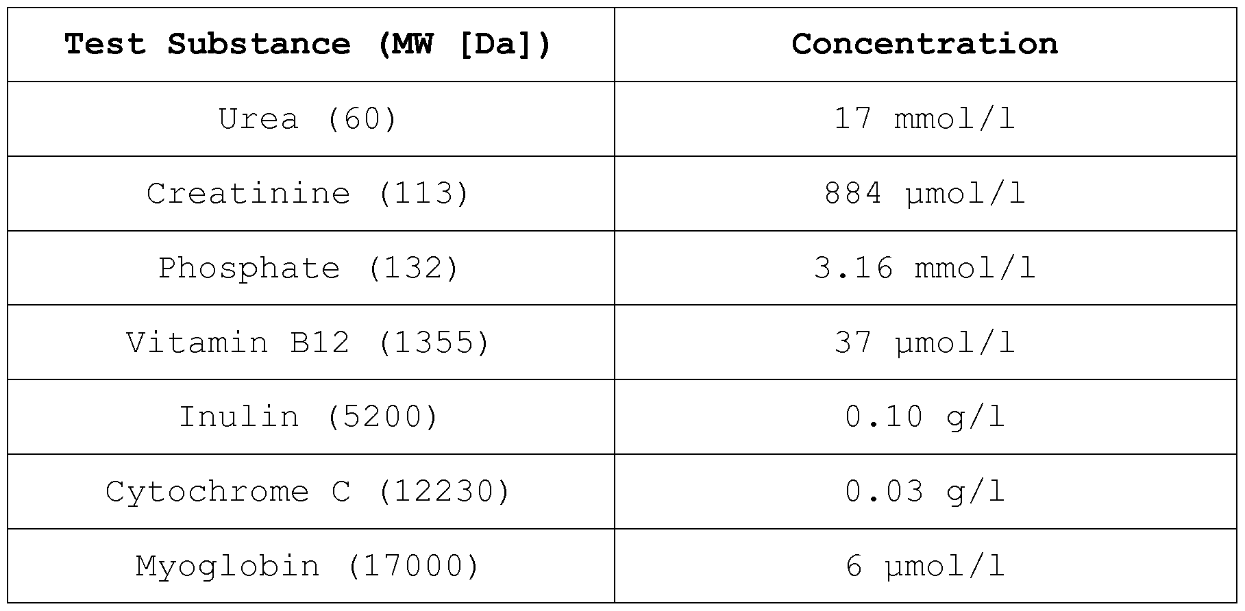
Claims
Priority Applications (17)
| Application Number | Priority Date | Filing Date | Title |
|---|---|---|---|
| EP18179492.6A EP3427814B1 (en) | 2014-02-06 | 2015-02-05 | Hemodialyzer for blood purification |
| ES15702769T ES2701847T3 (en) | 2014-02-06 | 2015-02-05 | Hemodialyzer to purify the blood |
| EP15702769.9A EP3102312B1 (en) | 2014-02-06 | 2015-02-05 | Hemodialyzer for blood purification |
| PL15702769T PL3102312T3 (en) | 2014-02-06 | 2015-02-05 | Hemodialyzer for blood purification |
| AU2015214950A AU2015214950B2 (en) | 2014-02-06 | 2015-02-05 | Hemodialyzer for blood purification |
| JP2016550735A JP6636437B2 (en) | 2014-02-06 | 2015-02-05 | Hemodialysis machine for blood purification |
| KR1020167024624A KR102316246B1 (en) | 2014-02-06 | 2015-02-05 | Hemodialyzer for blood purification |
| US15/115,951 US10661230B2 (en) | 2014-02-06 | 2015-02-05 | Hemodialyzer for blood purification |
| CN201580002612.7A CN105722582A (en) | 2014-02-06 | 2015-02-05 | Hemodialyzer for blood purification |
| KR1020217033439A KR102422691B1 (en) | 2014-02-06 | 2015-02-05 | Hemodialyzer for blood purification |
| CN202211244790.9A CN115445438A (en) | 2014-02-06 | 2015-02-05 | Hemodialyzer for blood purification |
| CA2938222A CA2938222C (en) | 2014-02-06 | 2015-02-05 | Hemodialyzer for blood purification |
| HK16112673.1A HK1224246A1 (en) | 2014-02-06 | 2016-11-03 | Hemodialyzer for blood purification |
| AU2018278913A AU2018278913B2 (en) | 2014-02-06 | 2018-12-12 | Hemodialyzer for blood purification |
| US16/851,439 US11273417B2 (en) | 2014-02-06 | 2020-04-17 | Hemodialyzer for blood purification |
| US17/590,097 US11666869B2 (en) | 2014-02-06 | 2022-02-01 | Hemodialyzer for blood purification |
| US18/143,324 US20230271146A1 (en) | 2014-02-06 | 2023-05-04 | Hemodialyzer for blood purification |
Applications Claiming Priority (2)
| Application Number | Priority Date | Filing Date | Title |
|---|---|---|---|
| EP14154172.2 | 2014-02-06 | ||
| EP14154172 | 2014-02-06 |
Related Child Applications (2)
| Application Number | Title | Priority Date | Filing Date |
|---|---|---|---|
| US15/115,951 A-371-Of-International US10661230B2 (en) | 2014-02-06 | 2015-02-05 | Hemodialyzer for blood purification |
| US16/851,439 Continuation US11273417B2 (en) | 2014-02-06 | 2020-04-17 | Hemodialyzer for blood purification |
Publications (1)
| Publication Number | Publication Date |
|---|---|
| WO2015118046A1 true WO2015118046A1 (en) | 2015-08-13 |
Family
ID=50070383
Family Applications (1)
| Application Number | Title | Priority Date | Filing Date |
|---|---|---|---|
| PCT/EP2015/052365 WO2015118046A1 (en) | 2014-02-06 | 2015-02-05 | Hemodialyzer for blood purification |
Country Status (12)
| Country | Link |
|---|---|
| US (4) | US10661230B2 (en) |
| EP (2) | EP3427814B1 (en) |
| JP (2) | JP6636437B2 (en) |
| KR (2) | KR102422691B1 (en) |
| CN (3) | CN115445438A (en) |
| AU (2) | AU2015214950B2 (en) |
| CA (1) | CA2938222C (en) |
| ES (2) | ES2927071T3 (en) |
| HK (1) | HK1224246A1 (en) |
| PL (2) | PL3427814T3 (en) |
| PT (2) | PT3102312T (en) |
| WO (1) | WO2015118046A1 (en) |
Cited By (15)
| Publication number | Priority date | Publication date | Assignee | Title |
|---|---|---|---|---|
| EP3102314B1 (en) | 2014-02-06 | 2018-09-19 | Gambro Lundia AB | Membrane for blood purification |
| EP3388139A1 (en) | 2017-04-13 | 2018-10-17 | Gambro Lundia AB | Optimized hemodialyzer for blood purification |
| US10238785B2 (en) | 2015-05-15 | 2019-03-26 | Gambro Lundia Ab | Membrane and device for treating hemolytic events |
| US10369263B2 (en) | 2014-03-29 | 2019-08-06 | Novaflux Inc. | Blood processing cartridges and systems, and methods for extracorporeal blood therapies |
| US10399040B2 (en) | 2015-09-24 | 2019-09-03 | Novaflux Inc. | Cartridges and systems for membrane-based therapies |
| US10426884B2 (en) | 2015-06-26 | 2019-10-01 | Novaflux Inc. | Cartridges and systems for outside-in flow in membrane-based therapies |
| US10661230B2 (en) | 2014-02-06 | 2020-05-26 | Gambro Lundia Ab | Hemodialyzer for blood purification |
| WO2020178420A1 (en) | 2019-03-06 | 2020-09-10 | Gambro Lundia Ab | Blood treatment device comprising alkaline phosphatase |
| WO2021005173A1 (en) | 2019-07-09 | 2021-01-14 | Fresenius Medical Care Deutschland Gmbh | Dialysis device comprising two balancing chambers that are fluidically connected to one another |
| WO2021005164A1 (en) | 2019-07-09 | 2021-01-14 | Fresenius Medical Care Deutschland Gmbh | Dialysis machine having three balance chambers |
| CN112245691A (en) * | 2019-07-22 | 2021-01-22 | 巴克斯特医疗保健股份有限公司 | Method and system for preparing dialysate from raw water |
| WO2021138461A1 (en) * | 2019-12-31 | 2021-07-08 | Seastar Medical, Inc. | Devices and methods for reducing rejection of a transplanted organ in a recipient |
| US11278651B2 (en) | 2018-10-17 | 2022-03-22 | Gambro Lundia Ab | Membrane and device for treating restless leg syndrome |
| EP4201508A1 (en) | 2021-12-21 | 2023-06-28 | Gambro Lundia AB | Membrane coated with polydopamine and chondroitin and process for producing same |
| EP4201507A1 (en) | 2021-12-21 | 2023-06-28 | Gambro Lundia AB | Method for increasing the selectivity of a membrane |
Families Citing this family (7)
| Publication number | Priority date | Publication date | Assignee | Title |
|---|---|---|---|---|
| EP3398558A1 (en) | 2017-05-02 | 2018-11-07 | Carlo Andretta | In body perfusion system |
| ES2952665T3 (en) * | 2017-07-27 | 2023-11-03 | Asahi Kasei Medical Co Ltd | Blood purification device, procedure for obtaining the transmembrane pressure difference across the blood purification membrane, and procedure, device and program for determining the same |
| CN108760233A (en) * | 2018-05-30 | 2018-11-06 | 威海威高血液净化制品有限公司 | dialyzer pressure drop performance test liquid |
| JP6997314B2 (en) * | 2018-06-26 | 2022-02-04 | Nok株式会社 | Manufacturing method of porous hollow fiber membrane for humidification |
| EP3809417A1 (en) | 2019-10-14 | 2021-04-21 | Gambro Lundia AB | Determining internal filtration rate within a capillary dialyzer |
| WO2021100811A1 (en) * | 2019-11-20 | 2021-05-27 | ニプロ株式会社 | Hollow fiber membrane module |
| CN111001316A (en) * | 2020-01-02 | 2020-04-14 | 李友来 | Ultrafiltration membrane, preparation method thereof, super-hydrophilic treatment method thereof and water purification equipment |
Citations (3)
| Publication number | Priority date | Publication date | Assignee | Title |
|---|---|---|---|---|
| GB2009034A (en) * | 1977-11-30 | 1979-06-13 | Monsanto Co | Crimped hollow fibers for fluid separations, bundles containing the hollow fibers, and apparatus and process for separating fluids |
| EP2253367A1 (en) * | 2009-05-20 | 2010-11-24 | Gambro Lundia AB | Membranes having improved performance |
| US20120305487A1 (en) * | 2011-05-31 | 2012-12-06 | Gambro Lundia Ab | Method for Treating Anemia in Hemodialysis Patients |
Family Cites Families (35)
| Publication number | Priority date | Publication date | Assignee | Title |
|---|---|---|---|---|
| DE3426331A1 (en) | 1984-07-17 | 1986-01-30 | 6380 Bad Homburg Fresenius AG | ASYMMETRIC MICROPOROUS HOLLOW FIBER FOR HAEMODIALYSIS AND METHOD FOR THE PRODUCTION THEREOF |
| SE454847B (en) | 1987-08-31 | 1988-06-06 | Gambro Dialysatoren | DEVICE FOR DIFFUSION AND / OR FILTERING AND PROCEDURE FOR MANUFACTURING THIS DEVICE |
| DE19514540A1 (en) | 1995-04-20 | 1996-10-24 | Gambro Dialysatoren | Membrane sterilizable with heat |
| DE19518624C1 (en) | 1995-05-24 | 1996-11-21 | Akzo Nobel Nv | Synthetic separation membrane |
| JP3617194B2 (en) | 1995-06-30 | 2005-02-02 | 東レ株式会社 | Permselective separation membrane and method for producing the same |
| ES2237760T3 (en) * | 1995-06-30 | 2005-08-01 | Toray Industries, Inc. | MANUFACTURING PROCEDURE OF A SEMIPERMEABLE MEMBRANE OF POLISHULPHONE HOLLOW FIBERS. |
| EP0844015B1 (en) | 1996-11-21 | 2003-10-15 | Fresenius Medical Care Deutschland GmbH | Hollow fiber membrane separation device |
| CN1298397C (en) * | 1998-11-09 | 2007-02-07 | 旭化成医疗株式会社 | Blood purifying apparatus |
| JP3424810B2 (en) | 1998-11-17 | 2003-07-07 | 東洋紡績株式会社 | High performance blood purification membrane |
| DE10007327A1 (en) | 2000-02-17 | 2001-08-30 | Fresenius Medical Care De Gmbh | Filter device, preferably hollow fiber dialyzer with curled hollow fibers |
| DE10041619A1 (en) | 2000-05-22 | 2001-11-29 | Bayer Ag | Selective herbicides based on heteroaryloxyacetamides |
| EP1388364B1 (en) | 2001-04-18 | 2008-11-26 | Asahi Kasei Kuraray Medical Co., Ltd. | Asymmetric porous films and process for producing the same |
| JP4683402B2 (en) * | 2001-06-29 | 2011-05-18 | 旭化成クラレメディカル株式会社 | Hollow fiber membrane for blood purification, method for producing the same, and blood purifier |
| SE0203855L (en) | 2002-12-20 | 2004-06-21 | Gambro Lundia Ab | Perm-selective membrane |
| SE0203857L (en) * | 2002-12-20 | 2004-06-21 | Gambro Lundia Ab | Perm-selective membrane and process for its manufacture |
| TWI406703B (en) * | 2003-11-17 | 2013-09-01 | Asahi Kasei Medical Co Ltd | Purify blood with hollow fiber membrane and use its blood purifier |
| DE102004008220B4 (en) * | 2004-02-19 | 2006-01-12 | Membrana Gmbh | High-flux dialysis membrane with improved separation behavior |
| WO2006024902A1 (en) * | 2004-08-06 | 2006-03-09 | Asahi Kasei Medical Co., Ltd. | Polysulfone hemodialyzer |
| EP1710011A1 (en) | 2005-04-07 | 2006-10-11 | Gambro Lundia AB | Filtration membrane |
| CN2824949Y (en) * | 2005-06-17 | 2006-10-11 | 缪志俊 | An in-vitro molecule-absorbing circulating system |
| GB0608444D0 (en) | 2006-04-27 | 2006-06-07 | Binding Site The Ltd | Dialysis |
| US9616393B2 (en) | 2007-12-06 | 2017-04-11 | Asahi Kasei Medical Co., Ltd. | Porous hollow fiber membrane for treating blood |
| PL2113298T3 (en) | 2008-04-30 | 2013-11-29 | Gambro Lundia Ab | Hollow fibre membrane for hemodialysis with improved permeability and selectivity |
| JP2010046587A (en) * | 2008-08-20 | 2010-03-04 | Toyobo Co Ltd | Hollow fiber membrane module |
| EP2161072A1 (en) | 2008-09-03 | 2010-03-10 | Gambro Lundia AB | High cut-off hemodialysis membranes for the treatment of chronic hemodialysis patients |
| JP4873665B2 (en) | 2009-03-31 | 2012-02-08 | 旭化成クラレメディカル株式会社 | Hollow fiber membrane for blood purification |
| ATE531445T1 (en) | 2009-05-20 | 2011-11-15 | Gambro Lundia Ab | MEMBRANES WITH IMPROVED PERFORMANCE |
| EP2253370B1 (en) * | 2009-05-20 | 2014-10-01 | Gambro Lundia AB | Hollow fibre membranes having improved performance |
| EP2253369B1 (en) | 2009-05-20 | 2011-11-09 | Gambro Lundia AB | Membranes having improved performance |
| EP2380610B1 (en) * | 2010-04-20 | 2014-05-07 | Gambro Lundia AB | High cut-off hemodialysis membrane for use in liver dialysis |
| CN110079887B (en) * | 2011-02-04 | 2021-12-24 | 弗雷塞尼斯医疗保健控股公司 | Performance enhancing additives for fiber formation and polysulfone fibers |
| CN202740496U (en) | 2012-06-21 | 2013-02-20 | 甘布罗伦迪亚股份公司 | Capillary dialyzer |
| EP2815807A1 (en) | 2013-06-20 | 2014-12-24 | Gambro Lundia AB | Capillary dialyzer comprising crimped hollow fibres |
| PT3102312T (en) | 2014-02-06 | 2018-12-18 | Gambro Lundia Ab | Hemodialyzer for blood purification |
| KR102431427B1 (en) | 2014-02-06 | 2022-08-10 | 감브로 룬디아 아베 | Membrane for blood purification |
-
2015
- 2015-02-05 PT PT15702769T patent/PT3102312T/en unknown
- 2015-02-05 ES ES18179492T patent/ES2927071T3/en active Active
- 2015-02-05 PL PL18179492.6T patent/PL3427814T3/en unknown
- 2015-02-05 KR KR1020217033439A patent/KR102422691B1/en active IP Right Grant
- 2015-02-05 PL PL15702769T patent/PL3102312T3/en unknown
- 2015-02-05 PT PT181794926T patent/PT3427814T/en unknown
- 2015-02-05 CA CA2938222A patent/CA2938222C/en active Active
- 2015-02-05 KR KR1020167024624A patent/KR102316246B1/en active IP Right Grant
- 2015-02-05 ES ES15702769T patent/ES2701847T3/en active Active
- 2015-02-05 US US15/115,951 patent/US10661230B2/en active Active
- 2015-02-05 CN CN202211244790.9A patent/CN115445438A/en active Pending
- 2015-02-05 WO PCT/EP2015/052365 patent/WO2015118046A1/en active Application Filing
- 2015-02-05 AU AU2015214950A patent/AU2015214950B2/en active Active
- 2015-02-05 EP EP18179492.6A patent/EP3427814B1/en active Active
- 2015-02-05 EP EP15702769.9A patent/EP3102312B1/en active Active
- 2015-02-05 CN CN201580002612.7A patent/CN105722582A/en active Pending
- 2015-02-05 CN CN202010459087.4A patent/CN111545068A/en active Pending
- 2015-02-05 JP JP2016550735A patent/JP6636437B2/en active Active
-
2016
- 2016-11-03 HK HK16112673.1A patent/HK1224246A1/en unknown
-
2018
- 2018-12-12 AU AU2018278913A patent/AU2018278913B2/en active Active
-
2019
- 2019-12-17 JP JP2019227041A patent/JP6924253B2/en active Active
-
2020
- 2020-04-17 US US16/851,439 patent/US11273417B2/en active Active
-
2022
- 2022-02-01 US US17/590,097 patent/US11666869B2/en active Active
-
2023
- 2023-05-04 US US18/143,324 patent/US20230271146A1/en active Pending
Patent Citations (3)
| Publication number | Priority date | Publication date | Assignee | Title |
|---|---|---|---|---|
| GB2009034A (en) * | 1977-11-30 | 1979-06-13 | Monsanto Co | Crimped hollow fibers for fluid separations, bundles containing the hollow fibers, and apparatus and process for separating fluids |
| EP2253367A1 (en) * | 2009-05-20 | 2010-11-24 | Gambro Lundia AB | Membranes having improved performance |
| US20120305487A1 (en) * | 2011-05-31 | 2012-12-06 | Gambro Lundia Ab | Method for Treating Anemia in Hemodialysis Patients |
Non-Patent Citations (1)
| Title |
|---|
| BOSCHETTI-DE-FIERRO A ET AL: "Extended characterization of a new class of membranes for blood purification", INTERNATIONAL JOURNAL OF ARTIFICIAL ORGANS, MILAN, IT, vol. 36, no. 7, 1 July 2013 (2013-07-01), pages 455 - 463, XP009179227, ISSN: 0391-3988 * |
Cited By (28)
| Publication number | Priority date | Publication date | Assignee | Title |
|---|---|---|---|---|
| US11666869B2 (en) | 2014-02-06 | 2023-06-06 | Gambro Lundia Ab | Hemodialyzer for blood purification |
| EP3102314B1 (en) | 2014-02-06 | 2018-09-19 | Gambro Lundia AB | Membrane for blood purification |
| US11273416B2 (en) | 2014-02-06 | 2022-03-15 | Gambro Lundia Ab | Membrane for blood purification |
| US11273417B2 (en) | 2014-02-06 | 2022-03-15 | Gambro Lundia Ab | Hemodialyzer for blood purification |
| US11666868B2 (en) | 2014-02-06 | 2023-06-06 | Gambro Lundia Ab | Membrane for blood purification |
| US10661230B2 (en) | 2014-02-06 | 2020-05-26 | Gambro Lundia Ab | Hemodialyzer for blood purification |
| US10661231B2 (en) | 2014-02-06 | 2020-05-26 | Gambro Lundia Ab | Membrane for blood purification |
| US10369263B2 (en) | 2014-03-29 | 2019-08-06 | Novaflux Inc. | Blood processing cartridges and systems, and methods for extracorporeal blood therapies |
| US11446419B2 (en) | 2014-03-29 | 2022-09-20 | Novaflux Inc. | Blood processing cartridges and systems, and methods for extracorporeal blood therapies |
| US10238785B2 (en) | 2015-05-15 | 2019-03-26 | Gambro Lundia Ab | Membrane and device for treating hemolytic events |
| US10426884B2 (en) | 2015-06-26 | 2019-10-01 | Novaflux Inc. | Cartridges and systems for outside-in flow in membrane-based therapies |
| US11648341B2 (en) | 2015-06-26 | 2023-05-16 | Novaflux Inc. | Cartridges and systems for outside-in flow in membrane-based therapies |
| US10399040B2 (en) | 2015-09-24 | 2019-09-03 | Novaflux Inc. | Cartridges and systems for membrane-based therapies |
| US11701622B2 (en) | 2015-09-24 | 2023-07-18 | Novaflux Inc. | Cartridges and systems for membrane-based therapies |
| EP3388139A1 (en) | 2017-04-13 | 2018-10-17 | Gambro Lundia AB | Optimized hemodialyzer for blood purification |
| WO2018188973A1 (en) | 2017-04-13 | 2018-10-18 | Gambro Lundia Ab | Optimized hemodialyzer for blood purification |
| AT17734U1 (en) * | 2018-10-17 | 2023-01-15 | Gambro Lundia Ab | Diaphragm for treatment of Restless Leg Syndrome |
| US11278651B2 (en) | 2018-10-17 | 2022-03-22 | Gambro Lundia Ab | Membrane and device for treating restless leg syndrome |
| WO2020178420A1 (en) | 2019-03-06 | 2020-09-10 | Gambro Lundia Ab | Blood treatment device comprising alkaline phosphatase |
| WO2021005164A1 (en) | 2019-07-09 | 2021-01-14 | Fresenius Medical Care Deutschland Gmbh | Dialysis machine having three balance chambers |
| WO2021005173A1 (en) | 2019-07-09 | 2021-01-14 | Fresenius Medical Care Deutschland Gmbh | Dialysis device comprising two balancing chambers that are fluidically connected to one another |
| WO2021016188A3 (en) * | 2019-07-22 | 2021-03-04 | Baxter International Inc. | Method and system for preparing dialysis fluid from raw water |
| CN112245691A (en) * | 2019-07-22 | 2021-01-22 | 巴克斯特医疗保健股份有限公司 | Method and system for preparing dialysate from raw water |
| WO2021138461A1 (en) * | 2019-12-31 | 2021-07-08 | Seastar Medical, Inc. | Devices and methods for reducing rejection of a transplanted organ in a recipient |
| WO2023117812A1 (en) | 2021-12-21 | 2023-06-29 | Gambro Lundia Ab | Membrane coated with polydopamine and chondroitin and process for producing same |
| EP4201508A1 (en) | 2021-12-21 | 2023-06-28 | Gambro Lundia AB | Membrane coated with polydopamine and chondroitin and process for producing same |
| EP4201507A1 (en) | 2021-12-21 | 2023-06-28 | Gambro Lundia AB | Method for increasing the selectivity of a membrane |
| WO2023117808A1 (en) | 2021-12-21 | 2023-06-29 | Gambro Lundia Ab | Method for increasing the selectivity of a membrane |
Also Published As
Similar Documents
| Publication | Publication Date | Title |
|---|---|---|
| AU2018278913B2 (en) | Hemodialyzer for blood purification | |
| AU2019200697B2 (en) | Membrane for blood purification |
Legal Events
| Date | Code | Title | Description |
|---|---|---|---|
| 121 | Ep: the epo has been informed by wipo that ep was designated in this application |
Ref document number: 15702769 Country of ref document: EP Kind code of ref document: A1 |
|
| REEP | Request for entry into the european phase |
Ref document number: 2015702769 Country of ref document: EP |
|
| WWE | Wipo information: entry into national phase |
Ref document number: 2015702769 Country of ref document: EP |
|
| ENP | Entry into the national phase |
Ref document number: 2938222 Country of ref document: CA |
|
| WWE | Wipo information: entry into national phase |
Ref document number: 15115951 Country of ref document: US |
|
| ENP | Entry into the national phase |
Ref document number: 2015214950 Country of ref document: AU Date of ref document: 20150205 Kind code of ref document: A |
|
| ENP | Entry into the national phase |
Ref document number: 2016550735 Country of ref document: JP Kind code of ref document: A |
|
| NENP | Non-entry into the national phase |
Ref country code: DE |
|
| ENP | Entry into the national phase |
Ref document number: 20167024624 Country of ref document: KR Kind code of ref document: A |