WO2015115407A1 - 浄水器 - Google Patents
浄水器 Download PDFInfo
- Publication number
- WO2015115407A1 WO2015115407A1 PCT/JP2015/052156 JP2015052156W WO2015115407A1 WO 2015115407 A1 WO2015115407 A1 WO 2015115407A1 JP 2015052156 W JP2015052156 W JP 2015052156W WO 2015115407 A1 WO2015115407 A1 WO 2015115407A1
- Authority
- WO
- WIPO (PCT)
- Prior art keywords
- nozzle
- cartridge
- cartridge outlet
- female screw
- water purifier
- Prior art date
- Legal status (The legal status is an assumption and is not a legal conclusion. Google has not performed a legal analysis and makes no representation as to the accuracy of the status listed.)
- Ceased
Links
Images

Classifications
-
- C—CHEMISTRY; METALLURGY
- C02—TREATMENT OF WATER, WASTE WATER, SEWAGE, OR SLUDGE
- C02F—TREATMENT OF WATER, WASTE WATER, SEWAGE, OR SLUDGE
- C02F9/00—Multistage treatment of water, waste water or sewage
- C02F9/20—Portable or detachable small-scale multistage treatment devices, e.g. point of use or laboratory water purification systems
-
- C—CHEMISTRY; METALLURGY
- C02—TREATMENT OF WATER, WASTE WATER, SEWAGE, OR SLUDGE
- C02F—TREATMENT OF WATER, WASTE WATER, SEWAGE, OR SLUDGE
- C02F1/00—Treatment of water, waste water, or sewage
- C02F1/28—Treatment of water, waste water, or sewage by sorption
- C02F1/283—Treatment of water, waste water, or sewage by sorption using coal, charred products, or inorganic mixtures containing them
-
- C—CHEMISTRY; METALLURGY
- C02—TREATMENT OF WATER, WASTE WATER, SEWAGE, OR SLUDGE
- C02F—TREATMENT OF WATER, WASTE WATER, SEWAGE, OR SLUDGE
- C02F1/00—Treatment of water, waste water, or sewage
- C02F1/44—Treatment of water, waste water, or sewage by dialysis, osmosis or reverse osmosis
- C02F1/444—Treatment of water, waste water, or sewage by dialysis, osmosis or reverse osmosis by ultrafiltration or microfiltration
-
- C—CHEMISTRY; METALLURGY
- C02—TREATMENT OF WATER, WASTE WATER, SEWAGE, OR SLUDGE
- C02F—TREATMENT OF WATER, WASTE WATER, SEWAGE, OR SLUDGE
- C02F2201/00—Apparatus for treatment of water, waste water or sewage
- C02F2201/002—Construction details of the apparatus
- C02F2201/006—Cartridges
-
- C—CHEMISTRY; METALLURGY
- C02—TREATMENT OF WATER, WASTE WATER, SEWAGE, OR SLUDGE
- C02F—TREATMENT OF WATER, WASTE WATER, SEWAGE, OR SLUDGE
- C02F2307/00—Location of water treatment or water treatment device
- C02F2307/10—Location of water treatment or water treatment device as part of a potable water dispenser, e.g. for use in homes or offices
-
- E—FIXED CONSTRUCTIONS
- E03—WATER SUPPLY; SEWERAGE
- E03C—DOMESTIC PLUMBING INSTALLATIONS FOR FRESH WATER OR WASTE WATER; SINKS
- E03C2201/00—Details, devices or methods not otherwise provided for
- E03C2201/40—Arrangement of water treatment devices in domestic plumbing installations
Definitions
- the present invention relates to a water purifier that is mainly used at home and filters tap water and the like.
- a stationary water purifier in which a main body with a built-in filtration cartridge is installed beside a sink is known. After the tap water is sent to the filtration cartridge via the hose, purified water is discharged from a dedicated water discharge section.
- the stationary water purifier is generally characterized by a larger filtration cartridge and generally longer life than the water purifier attached to the faucet or the pot type water purifier.
- Patent Document 1 a structure in which a nozzle can be attached and detached using a one-touch coupler has been proposed so far. It can be easily detached and rotated.
- Patent Document 2 a nozzle attaching / detaching structure using a C-ring has also been proposed.
- a C-ring is accommodated in the case, and when used, the groove provided in the outer peripheral wall of the nozzle is fitted with the C-ring. For this reason, while the nozzle can rotate freely, it is prevented from coming off by water pressure or the like. And when removing a nozzle, since the groove
- the stationary water purifier shown in Patent Document 2 is less expensive than the one-touch coupler, but if the C-ring is made of metal, the nozzle may be damaged. If the material of the C-ring is made of resin, scratches can be reduced, but this time there is a concern that it will break due to repeated deformation. In addition, in the first place, the structure using deformation of the member may dramatically change the force when attaching and detaching due to a slight difference in diameter. Therefore, management is difficult from the viewpoint of production.
- An object of the present invention is to provide a stationary water purifier having an inexpensive structure in which a nozzle portion for discharging purified water can be easily attached and detached.
- the present invention comprises the following arrangement.
- a raw water intake, a filtration cartridge for purifying the raw water, a cartridge outlet for discharging purified water, and a nozzle for discharging the purified water flowing out from the cartridge outlet In the installed stationary water purifier, The water purifier in which the nozzle is rotatable 360 degrees with respect to the cartridge outlet and is detachable, and the nozzle and the cartridge outlet have a pair of engaging portions that restrict movement of the nozzle in the rotation axis direction.
- the part of the nozzle connected to the cartridge and the part of the cartridge outlet connected to the nozzle are provided with a pair of screws.
- the pair of screws includes a female screw included in the nozzle and a male screw included in the cartridge outlet portion.
- the nozzle is provided with a male screw storage space adjacent to the female screw and present in front of the nozzle,
- the cartridge outlet portion includes a female screw insertion portion that is adjacent to the male screw and exists on the filtration cartridge side,
- locking part used as the pair may be formed with the lower end surface of the said external thread accommodated in the said external thread storage space, and the upper end surface of the said internal thread penetrated by the said internal thread insertion part.
- the part of the nozzle connected to the cartridge and the part of the cartridge outlet connected to the nozzle are provided with a pair of screws.
- the pair of screws includes a male screw provided in the nozzle and a female screw provided in the cartridge outlet portion.
- the nozzle includes a female screw insertion portion that is adjacent to the male screw and is present in front of the nozzle,
- the cartridge outlet portion includes a male screw storage space that is adjacent to the female screw and is present on the filtration cartridge side,
- locking part used as the pair can be formed with the upper end surface of the said external thread accommodated in the said external thread storage space, and the lower end surface of the said internal thread penetrated by the said internal thread insertion part.
- Patent Document 1 requires a one-touch coupler
- Patent Document 2 requires a C-ring.
- the present invention is feasible and inexpensive without increasing the number of parts.
- the nozzle can be attached and detached, and the part that could not be cleaned can be kept clean. For example, since the nozzle can be dipped and washed, the inside of the nozzle can be easily cleaned.
- the stationary water purifier of the present embodiment includes a water purifier main body 1 and a faucet connection portion 2 connected to a water faucet, and a hose 3 that feeds water from the faucet connection portion 2 to the water purifier main body 1.
- a water tap is inserted into the raw water intake 4 located at the top of the tap connection 2. Tap water as raw water of the stationary water purifier of the present embodiment is taken from the raw water intake 4.
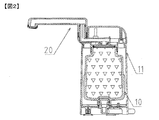
- the water purifier main body 1 includes a filtration cartridge 10 for purifying tap water sent from the hose 3, a storage case 11 for the filtration cartridge 10, and a water discharge unit 20 for discharging purified water.
- the filtration cartridge 10 is mainly composed of activated carbon and a hollow fiber membrane as a filter medium.
- the water discharge unit 20 will be described with reference to FIG.
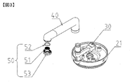
- the water discharge unit 20 includes a cartridge connection part 21 connected to the filtration cartridge 10, a cartridge outlet part 30 for feeding purified water, a nozzle 40 connected to the cartridge outlet part 30, and a rectifying unit 50 for adjusting the shape of the water flow.
- the cartridge outlet portion 30 may be integrated with the filtration cartridge 10 and the cartridge connection portion 21.
- the rectifying unit 50 includes a wire mesh 51, a packing 52, and a rectifying cap 53 for holding the wire mesh 51 and the packing 52.
- the wire net 51 may be mesh-shaped, and the material, size, and thickness are not limited.
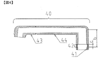
- the nozzle 40 has a substantially J-shaped hollow structure. One end is detachably connected to the cartridge outlet 30. The other end is liquid-tightly connected to the rectifying unit 50.
- the nozzle front part 43 and the nozzle rear part 44 are separate members, and these two members are connected in a liquid-tight manner later.
- ultrasonic welding may be used, or a rubber member may be sandwiched between the screws and fitting tabs.
- the cartridge outlet portion 30 is provided with a male screw 32 in a section of length a, and a female screw 41 which is paired with the male screw 32 is provided inside the nozzle 40.
- the female screw 41 is provided in a part of the nozzle 40.
- a straight part is provided in the section of length b behind the female screw 41.
- an internal thread storage space 42 having an inner diameter larger than the outer diameter of the external thread 32 and a length c is provided.
- a, b and c satisfy the following conditions. a ⁇ c ⁇ b.
- the mold structure may be an inner slide structure or an inclined pin may be used in production.
- the female screw 41 has a part without a screw.
- the male screw 32 will not be applied in order from the end of the screw, and the screw may be caught.
- the entire circumference is a screw.
- means for liquid-tight connection include ultrasonic welding, means for connecting with a screw or bayonet with a rubber member interposed therebetween, and the like. In this embodiment, the connection is made by ultrasonic welding.
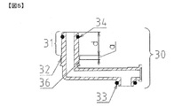
- the cartridge outlet 30 has a substantially hollow L shape. One end is connected to the cartridge connecting portion 21 and the other end is connected to the nozzle 40 in a liquid-tight manner.
- the cartridge connection part 21 side of the cartridge outlet part 30 is provided with an O-ring 33 and is liquid-tightly connected to the purified water passage hole at the center of the cartridge connection part 21.
- the O-ring 33 may be attached to the purified water passage hole of the cartridge connection portion 21. If the liquid-tight connection is possible, the O-ring 33 may be a flat packing, or the cartridge outlet 30 and the cartridge connector 21 may be ultrasonically welded and integrated.
- the connecting portion of the cartridge outlet portion 30 with the nozzle 40 has a cylindrical portion 31 having a length d, and the cylindrical portion 31 is inserted into the nozzle 40 for connection.
- the nozzle 40 is rotatable about the center line of the cylindrical portion 31 as an axis.
- the straight space between the cylindrical portion 31 of the cartridge outlet portion 30 and the nozzle 40 satisfies the following equation. d ⁇ b
- the cylindrical portion 31 is provided with an O-ring 34 and is connected to the nozzle 40 in a liquid-tight manner.
- An O-ring 34 may be provided on the nozzle 40 as long as it is connected in a liquid-tight manner.
- the cylindrical portion 31 is provided with the above-described male screw 32 in a section having a length a on the base side from the O-ring 34. Further, a female screw insertion portion 36 having a diameter smaller than the minimum inner diameter portion of the female screw 41 is provided at the root of the male screw 32.
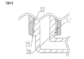
- FIG. 6 shows a state in which the nozzle 40 and the cartridge outlet 30 are connected. This will be described below with reference to FIG.
- the male screw 32 of the cartridge outlet portion 30 is accommodated in the male screw storage space 42 inside the nozzle 40.
- the female screw 41 of the nozzle 40 is inserted into the female screw insertion portion 36. In this state, the nozzle 40 is freely rotatable, and the male screw 32 and the female screw 41 are not engaged with each other, so that the nozzle 40 does not come off from the cartridge outlet 30.
- the lower end surface of the external thread 32 and the upper end surface of the female screw 41 become a locking portion, and the nozzle 40 does not come off. That is, the lower end surface of the external thread 32 and the upper end surface of the internal thread 41 serve as a pair of engaging portions that are provided at the cartridge outlet portion and the nozzle, respectively, and restrict the movement of the nozzle in the rotation axis direction.
- a step 35 protruding in the outer peripheral direction is provided at the lower part of the external thread 32.
- the step 35 is close to the inner peripheral wall of the nozzle 40 and plays a role of centering. Thereby, the play of the nozzle 40 is reduced and the sealing performance of the O-ring 34 is enhanced.
- the nozzle 40 when removing the nozzle 40 from the cartridge outlet 30, the nozzle 40 is rotated with the nozzle 40 pulled up. Thereby, the internal thread 41 of the nozzle 40 and the external thread 32 of the cartridge outlet 30 are engaged with each other. Further, by rotating the nozzle 40, the nozzle 40 moves upward along the screw and can be removed.
- the lower end of the nozzle 40 is extended in the direction of the rotation axis, and the pin or screw protruding from the outer peripheral side of the lower end to the inner peripheral side is connected to the step 35 of the cartridge outlet 30. It is good also as a structure inserted so that it may be located directly below.
- 35 can be a pair of locking portions provided at the nozzle and the cartridge outlet portion, respectively, for restricting the movement of the nozzle in the direction of the rotation axis.
- the pins or screws are attached after the nozzle and the cartridge outlet are connected.
- a pin or a screw that is a locking portion for restricting the movement of the nozzle in the rotation axis direction is removed, and then the nozzle is removed from the cartridge outlet.
- the nozzle 40 is provided with the female screw 41, and the screw 32 is provided at the cartridge outlet, but the screw may be reversed as long as this object can be achieved.
- the cartridge outlet portion is provided with a screw and a female screw insertion portion
- the nozzle is provided with a female screw and a male screw storage space.
- a female screw and a male screw storage space are provided in the cartridge outlet portion and a screw and a female screw insertion portion are provided in the nozzle may be used.
- the present invention can be applied not only to a water purifier but also to a faucet having a nozzle, but its application range is not limited thereto.
- Water purifier body 2 Faucet connection part 3: Hose 4: Raw water intake 10: Filtration cartridge 11: Storage case 20: Water discharge unit 21: Cartridge connection part 30: Cartridge outlet part 31: Cylindrical part 32: Male thread 33: O-ring 34: O-ring 35: Step 36: Female screw insertion part 40: Nozzle 41: Female screw 42: Male screw storage space 43: Nozzle front part 44: Nozzle rear part 50: Rectification unit 51: Wire mesh 52: Packing 53: Rectification cap
Landscapes
- Health & Medical Sciences (AREA)
- Clinical Laboratory Science (AREA)
- Life Sciences & Earth Sciences (AREA)
- Hydrology & Water Resources (AREA)
- Engineering & Computer Science (AREA)
- Environmental & Geological Engineering (AREA)
- Water Supply & Treatment (AREA)
- Chemical & Material Sciences (AREA)
- Organic Chemistry (AREA)
- Water Treatment By Sorption (AREA)
- Separation Using Semi-Permeable Membranes (AREA)
Abstract
本発明の目的は、据置型浄水器において、浄水を吐水するノズル部分を容易に着脱でる構造を提供することである。 上記目的を達成するために、本発明は、原水取水口と、原水を浄化するためのろ過カートリッジと、浄化された水を吐水するノズルを備えた据置型浄水器において、ノズルがカートリッジ出口部に対し、360度回転自在で、着脱可能であり、ノズルおよびカートリッジ出口部には、ノズルの回転軸方向への動きを制限する対となる係止部を備えたことを特徴とする。
Description
本発明は、主に家庭で使用し、水道水などをろ過する浄水器に関する。
従来から、ろ過カートリッジを内蔵した本体を、シンクの横に設置する据置型浄水器が知られている。水道水は、ホースを介してろ過カートリッジへ送水された後、専用の吐水部から浄水が吐水される。据置型浄水器は、蛇口に取り付ける浄水器やポット型浄水器よりも、一般的にろ過カートリッジが大きく、概して高寿命であることが特徴である。
ただし据置型浄水器の問題点の一つとして、シンクの横に設置して使用するため、シンクからの跳ね水の影響を受け、汚れやすいことが挙げられる。特に、浄水が吐水されるノズル部分の汚れが気になるというユーザーは多く、ノズルを取り外し洗浄したいという要望がある。
特許文献1に示すように、これまでにワンタッチカプラを利用して、ノズルを着脱できる構造が提案されている。容易に着脱できると共に、回転自在である。
一方で、特許文献2に示すように、Cリングを利用したノズル着脱構造も提案されている。ケースの中にCリングが収納されており、使用時は、ノズルの外周壁に設けられた溝とCリングが嵌合する。このため、ノズルが自在に回転できつつも、水圧等で勝手に抜けないようになっている。そして、ノズルを取り外す際は、ノズルの溝にテーパがついているため、ノズルを強く引き上げると、Cリングがテーパに沿って拡がる構造となっている。
しかし、特許文献1に示す据置型浄水器では、ワンタッチカプラは複数の部材で構成された機構であるため、部材コストが高くなる。
また、特許文献2に示す据置型浄水器では、ワンタッチカプラよりも部品点数が少なく安価だが、Cリングが金属の場合、ノズルを傷つけてしまう可能性がある。Cリングの材質を樹脂にすれば、傷の低減を図れるが、今度は繰り返し変形により、折れてしまう懸念がある。また、そもそも部材の変形を利用した本構造は、わずかな径の違いで、着脱する際の力も劇的に変わってしまう可能性がある。そのため生産の観点からしても、管理が大変である。
本発明の目的は、浄水を吐水するノズル部分を容易に着脱でき、かつ安価な構造を有する据置型浄水器提供することである。
上記目的を達成するために、本発明は以下の構成からなる。
(1)原水取水口と、原水を浄化するためのろ過カートリッジと、浄化された水を流出するためのカートリッジ出口部と、浄化され、カートリッジ出口部から流出した水を吐水するためのノズルとを備えた据置型浄水器において、
ノズルがカートリッジ出口部に対し、360度回転自在で、着脱可能であり、ノズルおよびカートリッジ出口部には、ノズルの回転軸方向への動きを制限する対となる係止部がそれぞれある浄水器。
(1)原水取水口と、原水を浄化するためのろ過カートリッジと、浄化された水を流出するためのカートリッジ出口部と、浄化され、カートリッジ出口部から流出した水を吐水するためのノズルとを備えた据置型浄水器において、
ノズルがカートリッジ出口部に対し、360度回転自在で、着脱可能であり、ノズルおよびカートリッジ出口部には、ノズルの回転軸方向への動きを制限する対となる係止部がそれぞれある浄水器。
また、本発明の実施態様として以下のものがある。
(2)前記ノズルのカートリッジと結合する部分と、前記カートリッジ出口部のノズルと結合する部分とに、対となるねじを備え、
前記対となるねじは、前記ノズルが備えるめねじと、前記カートリッジ出口部が備えるおねじとからなり、
前記ノズルは、前記めねじに隣接し、ノズルの前の方に存在するおねじ収納空間を備え、
前記カートリッジ出口部は、前記おねじに隣接し、ろ過カートリッジ側に存在するめねじ挿通部を備え、
前記対となる係止部が、前記おねじ収納空間に収納された前記おねじの下端面と前記めねじ挿通部に挿通された前記めねじの上端面とで形成されうる上記浄水器。
(3)前記ノズルのカートリッジと結合する部分と前記カートリッジ出口部のノズルと結合する部分とに、対となるねじを備え、
前記対となるねじは、前記ノズルが備えるおねじと、前記カートリッジ出口部が備えるめねじとからなり、
前記ノズルは、前記おねじに隣接し、ノズルの前の方に存在するめねじ挿通部を備え、
前記カートリッジ出口部は、前記めねじに隣接し、ろ過カートリッジ側に存在するするおねじ収納空間を備え、
前記対となる係止部が、前記おねじ収納空間に収納された前記おねじの上端面と前記めねじ挿通部に挿通された前記めねじの下端面とで形成されうる上記浄水器。
(2)前記ノズルのカートリッジと結合する部分と、前記カートリッジ出口部のノズルと結合する部分とに、対となるねじを備え、
前記対となるねじは、前記ノズルが備えるめねじと、前記カートリッジ出口部が備えるおねじとからなり、
前記ノズルは、前記めねじに隣接し、ノズルの前の方に存在するおねじ収納空間を備え、
前記カートリッジ出口部は、前記おねじに隣接し、ろ過カートリッジ側に存在するめねじ挿通部を備え、
前記対となる係止部が、前記おねじ収納空間に収納された前記おねじの下端面と前記めねじ挿通部に挿通された前記めねじの上端面とで形成されうる上記浄水器。
(3)前記ノズルのカートリッジと結合する部分と前記カートリッジ出口部のノズルと結合する部分とに、対となるねじを備え、
前記対となるねじは、前記ノズルが備えるおねじと、前記カートリッジ出口部が備えるめねじとからなり、
前記ノズルは、前記おねじに隣接し、ノズルの前の方に存在するめねじ挿通部を備え、
前記カートリッジ出口部は、前記めねじに隣接し、ろ過カートリッジ側に存在するするおねじ収納空間を備え、
前記対となる係止部が、前記おねじ収納空間に収納された前記おねじの上端面と前記めねじ挿通部に挿通された前記めねじの下端面とで形成されうる上記浄水器。
ノズル回転機能とノズル着脱機能の両機能を備えた構造にしようとすると、従来は部材点数が多くなり、高価になっていた。たとえば特許文献1ではワンタッチカプラが、特許文献2ではCリングが必要であった。しかし本発明では、部品点数を増やさなくても、実現可能で安価である。
また、特許文献2のように樹脂の弾性を利用した着脱構造ではないため、ノズルの着脱に大きな力を必要としない。そのため誰でも簡単にノズルの取り外しができる。また繰り返し変形による疲労で部材が破損する恐れもない。
またノズルを着脱でき、洗浄できなかった箇所を清潔に保つことが可能となる。たとえば、ノズルを漬け置き洗いできるため、ノズル内部までの洗浄が容易になる。
他には、ノズルを取り外し、異なる機能を備えたアタッチメントや、異なるデザインに容易に交換できる。
発明の実施形態に係る浄水器において、図面を参照しながら説明する。なお、本発明は以下に示す実施の形態に限定されるものではなく、上記本発明の目的を達成できるものであればよい。
まず、本実施形態の構成部材について、図1および図2を用いて説明する。
本実施形態の据置型浄水器は、浄水器本体1と水道の蛇口に接続される蛇口接続部2、蛇口接続部2から浄水器本体1に水を送水するホース3により構成される。蛇口接続部2の上部に位置する原水取水口4に、水道の蛇口が挿入される。本実施形態の据置型浄水器の原水としての水道水は、原水取水口4から取り入れられる。
浄水器本体1は、ホース3から送水された水道水を浄化するろ過カートリッジ10と、ろ過カートリッジ10の収納ケース11、浄水を吐水する吐水ユニット20により構成される。ろ過カートリッジ10は、ろ材として主に活性炭と中空糸膜により構成される。
吐水ユニット20について、図3を用いて説明する。
吐水ユニット20は、ろ過カートリッジ10と接続するカートリッジ接続部21、浄水を送水するカートリッジ出口部30、カートリッジ出口部30と接続するノズル40、水流の形状を整えるための整流ユニット50により構成される。カートリッジ出口部30は、ろ過カートリッジ10やカートリッジ接続部21と、一体になっていてもよい。
整流ユニット50は、金網51、パッキン52、そして金網51とパッキン52を保持するための整流キャップ53により構成される。金網51は、メッシュ状のものであればよく、材質、大きさ、厚さを限定しない。
つぎにノズル40とカートリッジ出口部30について、図4および図5を用いて説明する。
ノズル40は、略J字型の中空構造をしている。一端は、カートリッジ出口部30と着脱可能に接続する。他端は、整流ユニット50と液密に接続する。J字型の中空構造を形成するために、本実施形態では、ノズル前方部43とノズル後方部44が別部材となっており、後にこれら2部材を液密に接続する構造となっている。液密に接続する手段としては、超音波溶着を用いたり、ゴム部材を挟んで、ねじや嵌合用のツメで留める手段が考えられる。
カートリッジ出口部30には、長さaの区間でおねじ32が設けられ、それと対となるめねじ41がノズル40の内側に設けられる。めねじ41は、ノズル40の一部の区間に設けられる。めねじ41よりも奥には、長さbの区間でストレート部が設けられる。そしてストレート部のうち、少なくともめねじ41側には、おねじ32の外径よりも大きい内径で長さcのおねじ収納空間42を有する。
a、bおよびcは以下の条件を満たす。
a≦c≦b 。
a≦c≦b 。
ところで、めねじ41よりも奥におねじ収納空間42を設ける場合、生産上、金型構造は内スライドの構造にしたり、傾斜ピンを用いたりすることがある。その場合、めねじ41には、一部ねじのない部分が生じる。
ねじのない部分があると、ねじ端部から順におねじ32が掛からず、ねじが噛み込む恐れがある。ねじの噛み込みを回避するために全周をねじにすることが好ましい。その場合、ねじ部が設けられている箇所を別部材で製作し、あとで液密に接続する必要がある。液密に接続する手段としては、超音波溶着や、ゴム部材を挟んで、ねじやバヨネットで接続する手段などが考えられる。本実施形態では、超音波溶着で接続している。
つぎにカートリッジ出口部30について説明する。
カートリッジ出口部30は、中空の略L字型をしている。一端は、カートリッジ接続部21と、他端は、ノズル40と液密に接続する。
カートリッジ出口部30のカートリッジ接続部21側は、Oリング33を備え、カートリッジ接続部21の中央の浄水通過孔に液密に接続される。Oリング33は、カートリッジ接続部21の浄水通過孔に取り付けても構わない。また、液密に接続できるならば、Oリング33を平パッキンにしても構わないし、カートリッジ出口部30とカートリッジ接続部21とを超音波溶着し、一体化してもよい。
またカートリッジ出口部30のノズル40との接続部は、長さdの円筒部31を有しており、円筒部31をノズル40に挿入し接続する。ノズル40は、円筒部31の中心線を軸にして、回転自在である。
カートリッジ出口部30の円筒部31とノズル40のストレート空間は、次式を満たす。
d≦b
円筒部31にはOリング34が備えられ、ノズル40と液密に接続される。液密に接続されるならば、ノズル40にOリング34を設けても構わない。
d≦b
円筒部31にはOリング34が備えられ、ノズル40と液密に接続される。液密に接続されるならば、ノズル40にOリング34を設けても構わない。
また円筒部31には、Oリング34よりも根元側に、上述したおねじ32が長さaの区間で設けられる。またおねじ32の根元には、めねじ41の最小内径部よりも小さい径のめねじ挿通部36を備えている。
図6に、ノズル40とカートリッジ出口部30を接続した状態を示す。以下図6を用いて説明する。カートリッジ出口部30のおねじ32は、ノズル40内部にあるおねじ収納空間42に収まる。また、ノズル40のめねじ41は、めねじ挿通部36に挿通される。この状態で、ノズル40は回転自由であり、またおねじ32とめねじ41とは噛み合わないため、ノズル40がカートリッジ出口部30から外れることはない。
またノズル40を上に引き上げたとしても、おねじ32の下端面とめねじ41の上端面とが係止部となり、ノズル40が抜けてしまうことはない。すなわち、おねじ32の下端面とめねじ41の上端面とは、カートリッジ出口部およびノズルにそれぞれ設けられる、ノズルの回転軸方向への動きを制限する対となる係止部となっている。
また、おねじ32の下部には、外周方向にせり出す段差35が設けられている。ノズル40とカートリッジ出口部30が接続された状態において、段差35は、ノズル40の内周壁と近接し、芯出しの役割をする。これにより、ノズル40のガタつきが軽減され、Oリング34のシール性が高まる。
ところで、ノズル40をカートリッジ出口部30から取り外す際は、ノズル40を引き上げた状態で、ノズル40を回転させる。これにより、ノズル40のめねじ41とカートリッジ出口部30のおねじ32が噛み合う。さらにノズル40を回転させることで、ノズル40は、ねじに沿って上方に移動し、取り外すことができる。
図には示していないが別の態様もある。図6に示すような接続状態から、ノズル40の下端部を回転軸方向に延長して、その下端部の外周側から内周側に突き出るピンまたはビスを、上記のカートリッジ出口部30の段差35の直下に位置するように、挿入する構成としてもよい。このようなピンまたはビスを設ける構成にすると、ノズルとカートリッジ出口部とにそれぞれねじがなく、単にお互いを挿入し合うことで着脱可能に接続する場合であっても、そのピンまたはビスと、段差35とを、ノズルおよびカートリッジ出口部にそれぞれ設けられる、ノズルの回転軸方向への動きを制限する対となる係止部とすることができる。この構成の場合、ピンまたはビスは、ノズルとカートリッジ出口部を接続後、取り付ける。またカートリッジ出口部からノズルを取り外す際には、まず、ノズルの回転軸方向への動きを制限する係止部であるピンまたはビスを取り外し、その後ノズルをカートリッジ出口部から取り外す。
図4、図5および図6に示した実施形態では、ノズル40にめねじ41、カートリッジ出口部におねじ32が設けられているが、本目的が達成できれば、ねじを逆にしても構わない。すなわち、図4、図5および図6に示したの実施形態においては、カートリッジ出口部におねじ、および、めねじ挿通部が設けられ、ノズルにめねじ、および、おねじ収納空間が設けられているが、逆の実施形態として、カートリッジ出口部にめねじ、およびおねじ収納空間が設けられ、ノズルにおねじ、および、めねじ挿通部が設けられている実施形態であってもよい。
本発明は、浄水器に限らずノズルを有する水栓などにも応用することができるが、その応用範囲が、これらに限られるものではない。
1:浄水器本体
2:蛇口接続部
3:ホース
4:原水取水口
10:ろ過カートリッジ
11:収納ケース
20:吐水ユニット
21:カートリッジ接続部
30:カートリッジ出口部
31:円筒部
32:おねじ
33:Oリング
34:Oリング
35:段差
36:めねじ挿通部
40:ノズル
41:めねじ
42:おねじ収納空間
43:ノズル前方部
44:ノズル後方部
50:整流ユニット
51:金網
52:パッキング
53:整流キャップ
2:蛇口接続部
3:ホース
4:原水取水口
10:ろ過カートリッジ
11:収納ケース
20:吐水ユニット
21:カートリッジ接続部
30:カートリッジ出口部
31:円筒部
32:おねじ
33:Oリング
34:Oリング
35:段差
36:めねじ挿通部
40:ノズル
41:めねじ
42:おねじ収納空間
43:ノズル前方部
44:ノズル後方部
50:整流ユニット
51:金網
52:パッキング
53:整流キャップ
Claims (3)
- 原水取水口と、原水を浄化するためのろ過カートリッジと、浄化された水を流出するためのカートリッジ出口部と、浄化され、カートリッジ出口部から流出した水を吐水するためのノズルとを備えた据置型浄水器において、
ノズルがカートリッジ出口部に対し、360度回転自在で、着脱可能であり、
ノズルおよびカートリッジ出口部には、ノズルの回転軸方向への動きを制限する対となる係止部がそれぞれある浄水器。 - 前記ノズルのカートリッジと結合する部分と、前記カートリッジ出口部のノズルと結合する部分とに、対となるねじを備え、
前記対となるねじは、前記ノズルが備えるめねじと、前記カートリッジ出口部が備えるおねじとからなり、
前記ノズルは、前記めねじに隣接し、ノズルの前の方に存在するおねじ収納空間を備え、
前記カートリッジ出口部は、前記おねじに隣接し、ろ過カートリッジ側に存在するめねじ挿通部を備え、
前記対となる係止部が、前記おねじ収納空間に収納された前記おねじの下端面と前記めねじ挿通部に挿通された前記めねじの上端面とで形成されうる請求項1に記載の浄水器。 - 前記ノズルのカートリッジと結合する部分と前記カートリッジ出口部のノズルと結合する部分とに、対となるねじを備え、
前記対となるねじは、前記ノズルが備えるおねじと、前記カートリッジ出口部が備えるめねじとからなり、
前記ノズルは、前記おねじに隣接し、ノズルの前の方に存在するめねじ挿通部を備え、
前記カートリッジ出口部は、前記めねじに隣接し、ろ過カートリッジ側に存在するするおねじ収納空間を備え、
前記対となる係止部が、前記おねじ収納空間に収納された前記おねじの上端面と前記めねじ挿通部に挿通された前記めねじの下端面とで形成されうる請求項1に記載の浄水器。
Priority Applications (2)
| Application Number | Priority Date | Filing Date | Title |
|---|---|---|---|
| JP2015525683A JPWO2015115407A1 (ja) | 2014-01-31 | 2015-01-27 | 浄水器 |
| CN201590000257.5U CN206126896U (zh) | 2014-01-31 | 2015-01-27 | 净水器 |
Applications Claiming Priority (2)
| Application Number | Priority Date | Filing Date | Title |
|---|---|---|---|
| JP2014-016975 | 2014-01-31 | ||
| JP2014016975 | 2014-01-31 |
Publications (1)
| Publication Number | Publication Date |
|---|---|
| WO2015115407A1 true WO2015115407A1 (ja) | 2015-08-06 |
Family
ID=53756980
Family Applications (1)
| Application Number | Title | Priority Date | Filing Date |
|---|---|---|---|
| PCT/JP2015/052156 Ceased WO2015115407A1 (ja) | 2014-01-31 | 2015-01-27 | 浄水器 |
Country Status (4)
| Country | Link |
|---|---|
| JP (1) | JPWO2015115407A1 (ja) |
| CN (1) | CN206126896U (ja) |
| TW (1) | TW201540351A (ja) |
| WO (1) | WO2015115407A1 (ja) |
Citations (3)
| Publication number | Priority date | Publication date | Assignee | Title |
|---|---|---|---|---|
| JPH07116655A (ja) * | 1993-10-21 | 1995-05-09 | Toray Ind Inc | 据置型浄水器 |
| JP2002066219A (ja) * | 2000-08-30 | 2002-03-05 | San-Ei Faucet Mfg Co Ltd | 浄水器 |
| JP2009019754A (ja) * | 2007-07-14 | 2009-01-29 | Ck Metals Co Ltd | 管継手及び管部材の連結構造 |
-
2015
- 2015-01-27 WO PCT/JP2015/052156 patent/WO2015115407A1/ja not_active Ceased
- 2015-01-27 JP JP2015525683A patent/JPWO2015115407A1/ja active Pending
- 2015-01-27 CN CN201590000257.5U patent/CN206126896U/zh not_active Expired - Lifetime
- 2015-01-29 TW TW104102980A patent/TW201540351A/zh unknown
Patent Citations (3)
| Publication number | Priority date | Publication date | Assignee | Title |
|---|---|---|---|---|
| JPH07116655A (ja) * | 1993-10-21 | 1995-05-09 | Toray Ind Inc | 据置型浄水器 |
| JP2002066219A (ja) * | 2000-08-30 | 2002-03-05 | San-Ei Faucet Mfg Co Ltd | 浄水器 |
| JP2009019754A (ja) * | 2007-07-14 | 2009-01-29 | Ck Metals Co Ltd | 管継手及び管部材の連結構造 |
Also Published As
| Publication number | Publication date |
|---|---|
| CN206126896U (zh) | 2017-04-26 |
| JPWO2015115407A1 (ja) | 2017-03-23 |
| TW201540351A (zh) | 2015-11-01 |
Similar Documents
| Publication | Publication Date | Title |
|---|---|---|
| CN106132504A (zh) | 卡扣到位的天然气过滤器 | |
| JP6435859B2 (ja) | 浄水器 | |
| CN102159293A (zh) | 过滤装置和过滤元件 | |
| CN212835684U (zh) | 一种进水组件及其淋浴装置 | |
| CN105664573B (zh) | 一种可拆洗的前置过滤器及其使用方法 | |
| WO2015115407A1 (ja) | 浄水器 | |
| CN211799155U (zh) | 水箱组件和净水设备 | |
| TW202133916A (zh) | 過濾器附件 | |
| KR101223933B1 (ko) | 정수기용 필터 베이스 | |
| JP2025064205A (ja) | アダプタ及びフィルタユニット | |
| CN212575727U (zh) | 一种粗水滤器 | |
| JP4932794B2 (ja) | フィルタユニット | |
| CN206965538U (zh) | 滤芯清洗结构及具有其的净水机滤芯 | |
| KR101509654B1 (ko) | 후렉시블 호스 | |
| CN214287050U (zh) | 一种前置过滤器 | |
| CN223628172U (zh) | 卧式精密滤芯式过滤器 | |
| CN223793003U (zh) | 过滤器 | |
| CN222468305U (zh) | 一种过滤装置 | |
| CN213285908U (zh) | 一种滤芯的外壳组件 | |
| JP5786274B2 (ja) | 浄水器 | |
| CN218935447U (zh) | 带滤网的洗衣机电磁阀快装转接头和进水阀组件连接结构 | |
| CN211198692U (zh) | 一种滤膜组件 | |
| CN214221483U (zh) | 一种水泵防护过滤器及使用该水泵防护过滤器的客车 | |
| CN214500176U (zh) | 一种新型角阀 | |
| KR102443768B1 (ko) | 주방용 싱크대 수전의 분사헤드 |
Legal Events
| Date | Code | Title | Description |
|---|---|---|---|
| ENP | Entry into the national phase |
Ref document number: 2015525683 Country of ref document: JP Kind code of ref document: A |
|
| 121 | Ep: the epo has been informed by wipo that ep was designated in this application |
Ref document number: 15744006 Country of ref document: EP Kind code of ref document: A1 |
|
| NENP | Non-entry into the national phase |
Ref country code: DE |
|
| 122 | Ep: pct application non-entry in european phase |
Ref document number: 15744006 Country of ref document: EP Kind code of ref document: A1 |