WO2015114905A1 - Apparatus - Google Patents
Apparatus Download PDFInfo
- Publication number
- WO2015114905A1 WO2015114905A1 PCT/JP2014/079859 JP2014079859W WO2015114905A1 WO 2015114905 A1 WO2015114905 A1 WO 2015114905A1 JP 2014079859 W JP2014079859 W JP 2014079859W WO 2015114905 A1 WO2015114905 A1 WO 2015114905A1
- Authority
- WO
- WIPO (PCT)
- Prior art keywords
- group
- specific terminal
- mbsfn
- terminal group
- information
- Prior art date
Links
Images


Classifications
-
- H—ELECTRICITY
- H04—ELECTRIC COMMUNICATION TECHNIQUE
- H04W—WIRELESS COMMUNICATION NETWORKS
- H04W4/00—Services specially adapted for wireless communication networks; Facilities therefor
- H04W4/06—Selective distribution of broadcast services, e.g. multimedia broadcast multicast service [MBMS]; Services to user groups; One-way selective calling services
-
- H—ELECTRICITY
- H04—ELECTRIC COMMUNICATION TECHNIQUE
- H04W—WIRELESS COMMUNICATION NETWORKS
- H04W72/00—Local resource management
- H04W72/30—Resource management for broadcast services
-
- H—ELECTRICITY
- H04—ELECTRIC COMMUNICATION TECHNIQUE
- H04W—WIRELESS COMMUNICATION NETWORKS
- H04W4/00—Services specially adapted for wireless communication networks; Facilities therefor
- H04W4/06—Selective distribution of broadcast services, e.g. multimedia broadcast multicast service [MBMS]; Services to user groups; One-way selective calling services
- H04W4/08—User group management
-
- H—ELECTRICITY
- H04—ELECTRIC COMMUNICATION TECHNIQUE
- H04W—WIRELESS COMMUNICATION NETWORKS
- H04W48/00—Access restriction; Network selection; Access point selection
- H04W48/16—Discovering, processing access restriction or access information
-
- H—ELECTRICITY
- H04—ELECTRIC COMMUNICATION TECHNIQUE
- H04W—WIRELESS COMMUNICATION NETWORKS
- H04W72/00—Local resource management
- H04W72/20—Control channels or signalling for resource management
- H04W72/23—Control channels or signalling for resource management in the downlink direction of a wireless link, i.e. towards a terminal
Landscapes
- Engineering & Computer Science (AREA)
- Computer Networks & Wireless Communication (AREA)
- Signal Processing (AREA)
- Multimedia (AREA)
- Computer Security & Cryptography (AREA)
- Mobile Radio Communication Systems (AREA)
Abstract
[Problem] To enable a multicast to be performed for a particular terminal group. [Solution] Provided is an apparatus equipped with: an acquisition unit that acquires channel configuration information indicating the configuration of multicast channels arranged in MBSFN subframes for a particular terminal group; and a control unit that notifies the particular terminal group of the channel configuration information.
Description
本開示は、装置に関する。
This disclosure relates to an apparatus.
セルラーネットワークにおいて、放送コンテンツのような同一のコンテンツを複数のユーザに配信する方式として、MBMS(Multicast Broadcast Multimedia Services)が実用化されている。とりわけLTE(Long Term Evolution)では、複数のセルの基地局が互いに同期して同一コンテンツを配信するMBSFN(MBMS over Single Frequency Network)が規格化されている。MBSFNにより、端末において、複数の基地局からの受信信号が合成され、受信品質が改善され得る。また、近年のトラフィックの増大への対応のため、さらに効率的なMBSFNの運用が期待されている。
技術が提案されている。 In a cellular network, MBMS (Multicast Broadcast Multimedia Services) has been put into practical use as a method for distributing the same content such as broadcast content to a plurality of users. In particular, in LTE (Long Term Evolution), MBSFN (MBMS over Single Frequency Network) in which base stations of a plurality of cells deliver the same content in synchronization with each other is standardized. With MBSFN, reception signals from a plurality of base stations can be combined at a terminal, and reception quality can be improved. Further, more efficient MBSFN operation is expected to cope with the recent increase in traffic.
Technology has been proposed.
例えば、非特許文献1には、MBMS及びMBSFNに関して規格化された技術が開示されている。
For example, Non-Patent Document 1 discloses a standardized technique regarding MBMS and MBSFN.
しかし、上記特許文献1に開示されている技術では、MBSFNエリアに位置する全ての端末へのマルチキャストが想定されているので、特定の端末グループへのマルチキャストを行うことができない。
However, in the technique disclosed in Patent Document 1, since multicast to all terminals located in the MBSFN area is assumed, multicast to a specific terminal group cannot be performed.
なお、例えば、フェムトセルのようなCSG(Closed Subscriber Group)セルでは、端末のアクセス権(CSG UEであるか又は非CSG UEであるか)に応じて、当該端末に提供されるサービスの品質及び/又は種類が変わり得る。しかしながら、やはり、CSGへのマルチキャストを行うことはできない。
For example, in a CSG (Closed Subscriber Group) cell such as a femto cell, depending on the access right of the terminal (whether it is a CSG UE or a non-CSG UE), the quality of service provided to the terminal and / Or the type can change. However, it is still impossible to perform multicast to the CSG.
そこで、特定の端末グループへのマルチキャストを行うことを可能にする仕組みが提供されることが望ましい。
Therefore, it is desirable to provide a mechanism that enables multicasting to a specific terminal group.
本開示によれば、特定の端末グループ用のMBSFN(Multimedia Broadcast Multicast Service(MBMS) over Single Frequency Network)サブフレームに配置されるマルチキャストチャネルの構成を示すチャネル構成情報を取得する取得部と、上記チャネル構成情報を上記特定の端末グループに通知する制御部と、を備える装置が提供される。
According to the present disclosure, an acquisition unit that acquires channel configuration information indicating a configuration of a multicast channel arranged in an MBSFN (Multimedia Broadcast Multicast Service (MBMS) over Single Frequency Network) subframe for a specific terminal group, and the channel And a control unit that notifies configuration information to the specific terminal group.
また、本開示によれば、特定の端末グループ用の識別情報を取得する取得部と、上記識別情報を使用して、上記特定の端末グループ用のMBSFNサブフレームに配置されるマルチキャストチャネルの構成を示すチャネル構成情報であって、基地局により上記特定の端末グループに通知される上記チャネル構成情報を取得する制御部と、を備える装置が提供される。
Further, according to the present disclosure, an acquisition unit that acquires identification information for a specific terminal group and a configuration of a multicast channel arranged in the MBSFN subframe for the specific terminal group using the identification information are configured. And a control unit that acquires the channel configuration information that is notified to the specific terminal group by a base station.
また、本開示によれば、特定の端末グループ用のMBSFNサブフレームを決定する決定部、を備える装置が提供される。
Also, according to the present disclosure, there is provided an apparatus including a determining unit that determines an MBSFN subframe for a specific terminal group.
以上説明したように本開示によれば、特定の端末グループへのマルチキャストを行うことが可能になる。なお、上記の効果は必ずしも限定的なものではなく、上記効果とともに、又は上記効果に代えて、本明細書に示されたいずれかの効果、又は本明細書から把握され得る他の効果が奏されてもよい。
As described above, according to the present disclosure, it is possible to perform multicast to a specific terminal group. The above effects are not necessarily limited, and any of the effects shown in the present specification or other effects that can be grasped from the present specification are exhibited together with or in place of the above effects. May be.
以下に添付の図面を参照しながら、本開示の好適な実施の形態について詳細に説明する。なお、本明細書及び図面において、実質的に同一の機能構成を有する構成要素については、同一の符号を付することにより重複説明を省略する。
Hereinafter, preferred embodiments of the present disclosure will be described in detail with reference to the accompanying drawings. In addition, in this specification and drawing, about the component which has the substantially same function structure, duplication description is abbreviate | omitted by attaching | subjecting the same code | symbol.
なお、説明は以下の順序で行うものとする。
1.はじめに
2.通信システムの概略的な構成
3.第1の実施形態
3.1.制御装置の構成
3.2.スモール基地局の構成
3.3.端末装置の構成
3.4.処理の流れ
3.5.変形例
4.第2の実施形態
4.1.制御装置の構成
4.2.スモール基地局の構成
4.3.端末装置の構成
4.4.処理の流れ
4.5.変形例
5.第3の実施形態
5.1.概略
5.2.スモール基地局の構成
5.3.端末装置の構成
5.4.処理の流れ
5.5.変形例
6.応用例
6.1.制御装置に関する応用例
6.2.スモール基地局に関する応用例
6.3.端末装置に関する応用例
7.まとめ The description will be made in the following order.
1. 1.Introduction 2. Schematic configuration of communication system First embodiment 3.1. Configuration of control device 3.2. Configuration of small base station 3.3. Configuration of terminal device 3.4. Process flow 3.5. Modified example 4. Second Embodiment 4.1. Configuration of control device 4.2. Configuration of small base station 4.3. Configuration of terminal device 4.4. Process flow 4.5. Modification 5 Third Embodiment 5.1. Outline 5.2. Configuration of small base station 5.3. Configuration of terminal device 5.4. Flow of processing 5.5. Modification 6 Application example 6.1. Application examples related to control devices 6.2. Application examples related to small base stations 6.3. 6. Application examples related to terminal devices Summary
1.はじめに
2.通信システムの概略的な構成
3.第1の実施形態
3.1.制御装置の構成
3.2.スモール基地局の構成
3.3.端末装置の構成
3.4.処理の流れ
3.5.変形例
4.第2の実施形態
4.1.制御装置の構成
4.2.スモール基地局の構成
4.3.端末装置の構成
4.4.処理の流れ
4.5.変形例
5.第3の実施形態
5.1.概略
5.2.スモール基地局の構成
5.3.端末装置の構成
5.4.処理の流れ
5.5.変形例
6.応用例
6.1.制御装置に関する応用例
6.2.スモール基地局に関する応用例
6.3.端末装置に関する応用例
7.まとめ The description will be made in the following order.
1. 1.
<<1.はじめに>>
まず、図1~図12を参照して、MBMS及びMBSFNに関する技術を説明する。 << 1. Introduction >>
First, techniques related to MBMS and MBSFN will be described with reference to FIGS.
まず、図1~図12を参照して、MBMS及びMBSFNに関する技術を説明する。 << 1. Introduction >>
First, techniques related to MBMS and MBSFN will be described with reference to FIGS.
(MBSFNエリア)
MBSFNでは、複数の基地局が、互いに同期して同一のコンテンツを配信する。即ち、MBSFNでは、複数の基地局が、同一の無線リソースで同一のデータを送信する。当該複数の基地局のセル(即ち、複数のセル)は、MBSFNエリアと呼ばれる。各セルは、最大8個のMBSFNエリアに属することができる。以下、図1を参照して、MBSFNエリアの具体例を説明する。 (MBSFN area)
In MBSFN, a plurality of base stations distribute the same content in synchronization with each other. That is, in MBSFN, a plurality of base stations transmit the same data using the same radio resource. The cells of the plurality of base stations (that is, a plurality of cells) are called MBSFN areas. Each cell can belong to a maximum of 8 MBSFN areas. Hereinafter, a specific example of the MBSFN area will be described with reference to FIG.
図1は、MBSFNエリアの例を説明するための説明図である。図1を参照すると、#1~#15のセルが示されている。この例では、MBSFNエリア0は#1~#3、#5~#8のセルを含み、MBSFNエリア1は#7、#9、#10、#13のセルを含み、MBSFNエリア255は#8、#9、#11~#15のセルを含む。なお、#7のセルは、MBSFNエリア0及びMBSFNエリア1の両方に属する。また、#8のセルは、MBSFNエリア0及びMBSFNエリア255の両方に属する。また、#9のセルは、MBSFNエリア1及びMBSFNエリア255の両方に属する。また、#4のセルは、いずれのMBSFNエリアにも属さない。
FIG. 1 is an explanatory diagram for explaining an example of the MBSFN area. Referring to FIG. 1, cells # 1 to # 15 are shown. In this example, MBSFN area 0 includes cells # 1 to # 3 and # 5 to # 8, MBSFN area 1 includes cells # 7, # 9, # 10, and # 13, and MBSFN area 255 includes # 8. , # 9, and cells # 11 to # 15. Note that cell # 7 belongs to both MBSFN area 0 and MBSFN area 1. The cell # 8 belongs to both the MBSFN area 0 and the MBSFN area 255. The cell # 9 belongs to both the MBSFN area 1 and the MBSFN area 255. The cell # 4 does not belong to any MBSFN area.
(MBMSに関するチャネル)
MBMSのための論理チャネル、トランスポートチャネル及び物理チャネルが定められている。以下、この点について図2を参照して説明する。 (Channels related to MBMS)
Logical channels, transport channels, and physical channels for MBMS are defined. Hereinafter, this point will be described with reference to FIG.
MBMSのための論理チャネル、トランスポートチャネル及び物理チャネルが定められている。以下、この点について図2を参照して説明する。 (Channels related to MBMS)
Logical channels, transport channels, and physical channels for MBMS are defined. Hereinafter, this point will be described with reference to FIG.
図2は、MBMSのためのチャネルを説明するための説明図である。図2を参照すると、LTEにおいて定められている論理チャネル、トランスポートチャネル及び物理チャネルが示されている。とりわけ、MBMSのための論理チャネルとして、MCCH(Multicast Control Channel)及びMTCH(Multicast Traffic Channel)が定められている。MCCHは、MBSFNエリアコンフィギュレーションメッセージ(MBSFN Area Configuration message)及びMBMSカウンティング要求メッセージ(MBM Counting Request messega)などの制御情報を送信するためのチャネルである。また、MTCHは、MBMSのデータを送信するためのチャネルである。また、MBMSのための物理チャネルとして、PMCH(Physical Multicast Channel)が定められている。MCCHにマッピングされる制御情報及びMTCHにマッピングされるデータの両方が、トランスポートチャネルであるMCH(Multicast Channel)を通じてPMCHにマッピングされる。
FIG. 2 is an explanatory diagram for explaining a channel for MBMS. Referring to FIG. 2, logical channels, transport channels, and physical channels defined in LTE are shown. In particular, MCCH (Multicast Control Channel) and MTCH (Multicast Traffic Channel) are defined as logical channels for MBMS. MCCH is a channel for transmitting control information such as an MBSFN area configuration message (MBSFN Area Configuration message) and an MBMS counting request message (MBM Counting Request messega). MTCH is a channel for transmitting MBMS data. Also, PMCH (Physical Multicast Channel) is defined as a physical channel for MBMS. Both control information mapped to MCCH and data mapped to MTCH are mapped to PMCH through MCH (Multicast Channel) which is a transport channel.
(MBSFNサブフレーム)
MBSFNの送信は、MBSFNサブフレームで行われる。MBSFNサブフレームは、無線フレーム割当て期間(Radio Frame Allocation Period)、無線フレーム割当てオフセット(Radio Frame Allocation Offset)、及びサブフレーム割当て(Subframe Allocation)により示される。以下、図3を参照して、MBSFNサブフレームの具体例を説明する。 (MBSFN subframe)
The MBSFN transmission is performed in the MBSFN subframe. The MBSFN subframe is indicated by a radio frame allocation period, a radio frame allocation offset, and a subframe allocation. Hereinafter, a specific example of the MBSFN subframe will be described with reference to FIG.
図3は、MBSFNサブフレームの例を説明するための説明図である。図3を参照すると、各SFN(System Frame Number)の無線フレームに含まれるサブフレームが示されている。この例では、無線フレーム割当て期間は8であり、無線フレーム割当てオフセットは2である。また、サブフレーム割当ては、4フレームパターン(24ビット)である。そのため、「SFN mod 8 =2」を満たすSFN(即ち、2、10、18などのSFN)の無線フレームと、その後に続く3つの無線フレームとが、MBSFNのための無線フレームである。また、この例では、FDD(Frequency Division Duplexing)が採用され、サブフレーム割当ては、「011010 011010 011010 011010」である。FDDが採用される場合には、サブフレーム割当ての各ビットは、#1、#2、#3、#6、#7及び#8のサブフレームを示すので、上記無線フレームのうちの#2、#3及び#7のサブフレームが、MBSFNサブフレームである。
FIG. 3 is an explanatory diagram for explaining an example of the MBSFN subframe. Referring to FIG. 3, subframes included in each SFN (System Frame Number) radio frame are shown. In this example, the radio frame allocation period is 8 and the radio frame allocation offset is 2. The subframe allocation is a 4-frame pattern (24 bits). Therefore, a radio frame of SFN that satisfies “SFN mod 8 = 2” (that is, SFN such as 2, 10, 18, etc.) and the subsequent three radio frames are radio frames for MBSFN. In this example, FDD (Frequency Division Duplexing) is adopted, and the subframe allocation is “011010 011010 011010 011010”. When FDD is adopted, each bit of subframe allocation indicates subframes # 1, # 2, # 3, # 6, # 7, and # 8, so # 2 of the above radio frames, The # 3 and # 7 subframes are MBSFN subframes.
システム情報及びページング情報が送信されるサブフレームは、MBSFNサブフレームとして使用されない。よって、FDDが採用される場合には、#0、#4、#5及び#9のサブフレームは、MBSFNサブフレームとして使用されない。また、TDD(Time Division Duplexing)が採用される場合には、#0、#1、#2、#5及び#6のサブフレームは、MBSFNサブフレームとして使用されない。
The subframe in which system information and paging information are transmitted is not used as an MBSFN subframe. Therefore, when FDD is adopted, the subframes # 0, # 4, # 5, and # 9 are not used as MBSFN subframes. When TDD (Time Division Duplexing) is adopted, the subframes # 0, # 1, # 2, # 5, and # 6 are not used as MBSFN subframes.
なお、MBSFNサブフレームは、例えば、SIB(System Information Block)2の中で端末装置に通知される。これにより、端末装置は、MBSFNエリアを知ることができる。また、MBSFNエリアごとのMBSFNサブフレームは、後述するように、MCCHにマッピングされる制御情報(MBSFNエリアコンフィギュレーションメッセージ)の中でも端末装置に通知される。
The MBSFN subframe is notified to the terminal device in, for example, an SIB (System Information Block) 2. Thereby, the terminal device can know the MBSFN area. Also, the MBSFN subframe for each MBSFN area is notified to the terminal device even in control information (MBSFN area configuration message) mapped to the MCCH, as will be described later.
(リファレンス信号)
MBSFNサブフレームは、MBSFN領域(MBSFN Region)及び非MBSFN領域(Non-MBSFN Region)を含む。PMCHは、MBSFN領域に配置されるので、MCCHにマッピングされる制御情報及びMTCHにマッピングされるデータは、とりわけMBSFN領域内で送信される。 (Reference signal)
The MBSFN subframe includes an MBSFN region (MBSFN Region) and a non-MBSFN region (Non-MBSFN Region). Since the PMCH is arranged in the MBSFN region, the control information mapped to the MCCH and the data mapped to the MTCH are transmitted especially in the MBSFN region.
また、MBSFNエリアに属するセルの基地局は、MBSFNサブフレームのうちのとりわけMBSFN領域内で、同一の信号を送信する。そのため、これらの基地局は、MBSFN領域内ではセル固有のリファレンス信号(Cell-specific Reference Signal:CRS)を送信しない。その代わりに、これらの基地局は、MBSFN用のリファレンス信号であるMBSFNリファレンス信号(MBSFN-RS)を送信する。MBSFN-RSは、MBSFNエリアに属する全てのセルにおいて、同一の無線リソース(即ち、同一のリソースエレメント)で送信される。以下、これらの点について図4を参照して具体例を説明する。
Also, the base station of the cell belonging to the MBSFN area transmits the same signal, particularly in the MBSFN area of the MBSFN subframe. Therefore, these base stations do not transmit a cell-specific reference signal (CRS) in the MBSFN area. Instead, these base stations transmit an MBSFN reference signal (MBSFN-RS) which is a reference signal for MBSFN. The MBSFN-RS is transmitted with the same radio resource (that is, the same resource element) in all cells belonging to the MBSFN area. Hereinafter, specific examples of these points will be described with reference to FIG.
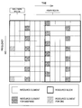
図4は、MBSFNサブフレームで送信される信号の例を説明するための説明図である。図4を参照すると、MBSFNサブフレーム内で時間方向に並ぶ2つのリソースブロック(RB)が示されている。この例では、MBSFNサブフレームは、時間方向において12個のOFDMシンボルを含む。また、MBSFNサブフレームは、12個のOFDMシンボルのうちの最初の2つのOFDMシンボルにわたる非MBSFN領域と、その後に続くMBSFN領域とを含む。非MBSFN領域では、CRSが送信され得る。一方、MBSFN領域では、MBSFNエリアに属するセル間で共通のMBSFN-RSが送信される。また、MBSFN領域では、MCCHにマッピングされる制御情報及び/又はMTCHにマッピングされるデータが送信される。
FIG. 4 is an explanatory diagram for explaining an example of a signal transmitted in the MBSFN subframe. Referring to FIG. 4, two resource blocks (RBs) arranged in the time direction in the MBSFN subframe are shown. In this example, the MBSFN subframe includes 12 OFDM symbols in the time direction. Also, the MBSFN subframe includes a non-MBSFN region that extends over the first two OFDM symbols of the 12 OFDM symbols, and an MBSFN region that follows the non-MBSFN region. In the non-MBSFN region, CRS may be transmitted. On the other hand, in the MBSFN area, a common MBSFN-RS is transmitted between cells belonging to the MBSFN area. In the MBSFN region, control information mapped to MCCH and / or data mapped to MTCH are transmitted.
なお、MBSFNサブフレーム以外のサブフレームでは、CRSが送信される。当該CRSは、セルの選択、チャネル推定及び同期検波などのために使用される。以下、図5及び図6を参照して、CRSの具体例を説明する。
Note that CRS is transmitted in subframes other than the MBSFN subframe. The CRS is used for cell selection, channel estimation, synchronous detection, and the like. Hereinafter, a specific example of CRS will be described with reference to FIGS. 5 and 6.
図5は、通常のサブフレーム内で送信されるCRSの例を説明するための説明図である。図5を参照すると、通常のサブフレーム内で時間方向に並ぶ2つのリソースブロック(RB)が示されている。通常のサブフレームは、時間方向において14個のOFDMシンボルを含む。CRSは、各RB内の所定のリソースエレメント(RE)で送信される。なお、上記所定のREは、セルごとに設定される。
FIG. 5 is an explanatory diagram for explaining an example of CRS transmitted in a normal subframe. Referring to FIG. 5, two resource blocks (RBs) arranged in the time direction in a normal subframe are shown. A normal subframe includes 14 OFDM symbols in the time direction. The CRS is transmitted by a predetermined resource element (RE) in each RB. The predetermined RE is set for each cell.
図6は、拡張サイクリックプレフィクス(Extended Cyclic Prefix)が使用される場合のサブフレーム内で送信されるCRSの例を説明するための説明図である。図6を参照すると、拡張サイクリックプレフィクスが使用される場合のサブフレーム内で時間方向に並ぶ2つのリソースブロック(RB)が示されている。この場合のサブフレームは、時間方向において12個のOFDMシンボルを含む。この場合も、CRSは、各RB内の所定のリソースエレメント(RE)で送信される。なお、上記所定のREは、セルごとに設定される。
FIG. 6 is an explanatory diagram for explaining an example of CRS transmitted in a subframe when an extended cyclic prefix (Extended Cyclic Prefix) is used. Referring to FIG. 6, two resource blocks (RBs) arranged in the time direction in a subframe when the extended cyclic prefix is used are shown. The subframe in this case includes 12 OFDM symbols in the time direction. Also in this case, the CRS is transmitted by a predetermined resource element (RE) in each RB. The predetermined RE is set for each cell.
(MCCH、MTCH及びPMCH)
-MBSFNエリアとMCCHとの関係
1つのMCCHは、1つのMBSFNエリアに対応する。即ち、MCCHは、セルが属するMBSFNエリアごとに存在する。 (MCCH, MTCH and PMCH)
-Relationship between MBSFN area and MCCH One MCCH corresponds to one MBSFN area. That is, the MCCH exists for each MBSFN area to which the cell belongs.
-MBSFNエリアとMCCHとの関係
1つのMCCHは、1つのMBSFNエリアに対応する。即ち、MCCHは、セルが属するMBSFNエリアごとに存在する。 (MCCH, MTCH and PMCH)
-Relationship between MBSFN area and MCCH One MCCH corresponds to one MBSFN area. That is, the MCCH exists for each MBSFN area to which the cell belongs.
-SIB13
SIB13は、MCCHが配置されるサブフレームなどを示し、端末装置に通知される。より具体的には、SIB13は、MCCH反復期間(MCCH Repetition Period)、MCCHオフセット及びサブフレーム割当て情報(Subframe Allocation Information)などを含む。以下、図7を参照して、MCCHが配置されるサブフレームの具体例を説明する。 -SIB13
TheSIB 13 indicates a subframe in which the MCCH is arranged and is notified to the terminal device. More specifically, the SIB 13 includes an MCCH repetition period, an MCCH offset, and subframe allocation information. Hereinafter, a specific example of a subframe in which MCCH is arranged will be described with reference to FIG.
SIB13は、MCCHが配置されるサブフレームなどを示し、端末装置に通知される。より具体的には、SIB13は、MCCH反復期間(MCCH Repetition Period)、MCCHオフセット及びサブフレーム割当て情報(Subframe Allocation Information)などを含む。以下、図7を参照して、MCCHが配置されるサブフレームの具体例を説明する。 -SIB13
The
図7は、MCCHが配置されるサブフレームの例を説明するための説明図である。図7を参照すると、各SFN(System Frame Number)の無線フレームに含まれるサブフレームが示されている。この例のMBSFNサブフレームは、図3に示されるMBSFNサブフレームと同一である。この例では、MCCH反復期間は32であり、MCCHオフセットは5である。そのため、「SFN mod 32 =5」を満たすSFN(即ち、5、37などのSFN)の無線フレームが、MCCHが配置される無線フレームである。さらに、この例では、サブフレーム割当て情報が、「010000」である。FDDが採用される場合には、サブフレーム割当ての各ビットは、#1、#2、#3、#6、#7及び#8のサブフレームを示すので、上記無線フレームのうちの#2のサブフレームが、MCCHが配置されるサブフレームである。このように、MCCHは、MBSFNサブフレームの中に定期的に配置される。
FIG. 7 is an explanatory diagram for explaining an example of a subframe in which MCCH is arranged. Referring to FIG. 7, subframes included in a radio frame of each SFN (System Frame Number) are shown. The MBSFN subframe in this example is the same as the MBSFN subframe shown in FIG. In this example, the MCCH repetition period is 32 and the MCCH offset is 5. Therefore, a radio frame of SFN (that is, SFN such as 5, 37) satisfying “SFN mod 32 = 5” is a radio frame in which MCCH is arranged. Further, in this example, the subframe allocation information is “010000”. When FDD is adopted, each bit of subframe allocation indicates subframes # 1, # 2, # 3, # 6, # 7, and # 8. A subframe is a subframe in which MCCH is arranged. Thus, the MCCH is periodically arranged in the MBSFN subframe.
なお、MCCH及びMTCHはMAC(Media Access Control)レイヤで多重されるが、端末装置はMACヘッダの多重情報によりMCCH及びMTCHを復調できる。
In addition, although MCCH and MTCH are multiplexed in a MAC (Media Access Control) layer, the terminal device can demodulate MCCH and MTCH by multiplexing information in the MAC header.
-MBSFNエリアコンフィギュレーションメッセージ
MCCHには、MBSFNエリアコンフィギュレーションメッセージがマッピングされる。 -MBSFN area configuration message An MBSFN area configuration message is mapped to the MCCH.
MCCHには、MBSFNエリアコンフィギュレーションメッセージがマッピングされる。 -MBSFN area configuration message An MBSFN area configuration message is mapped to the MCCH.
--共通サブフレーム割当て(CSA)
まず、MBSFNエリアコンフィギュレーションメッセージは、共通サブフレーム割当て(Common Subframe Allocation:CSA)パターンリスト、及びCSA期間を含み、これらの情報は、MBSFNエリアのMBSFNサブフレームを示す。CSAパターンリストは、無線フレーム割当て期間、無線フレーム割当てオフセット及びサブフレーム割当てを含む。以下、図8を参照して、これらの情報により示されるMBSFNサブフレームの具体例を説明する。 -Common subframe allocation (CSA)
First, the MBSFN area configuration message includes a common subframe allocation (CSA) pattern list and a CSA period, and these pieces of information indicate MBSFN subframes in the MBSFN area. The CSA pattern list includes a radio frame allocation period, a radio frame allocation offset, and a subframe allocation. A specific example of the MBSFN subframe indicated by these pieces of information will be described below with reference to FIG.
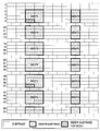
図8は、MBSFNサブフレームの例を説明するための説明図である。図8を参照すると、CSA期間にわたる無線フレームが示されている。この例では、CSA期間は、32無線フレームである。また、この例では、CSAパターンリストは、エントリ1及びエントリ2を含む。エントリ1では、無線フレーム割当て期間が16であり、無線フレーム割当てオフセットが0であり、サブフレーム割当てが1フレームパターン(6ビット)の「100100」である。よって、エントリ1のMBSFNサブフレームは、SFNが0及び16である2つの無線フレームの中の、#1及び#6のサブフレームである。エントリ2では、無線フレーム割当て期間が4であり、無線フレーム割当てオフセットが3であり、サブフレーム割当てが1フレームパターン(6ビット)の「001001」である。よって、エントリ2のMBSFNサブフレームは、SFNが3、7、11、15、19、23、27及び31である8つの無線フレームの中の、#3及び#8のサブフレームである。よって、この例では、MBSFNサブフレームとして、CSA期間の中の合計20個のサブフレームが示される。
FIG. 8 is an explanatory diagram for explaining an example of the MBSFN subframe. Referring to FIG. 8, a radio frame over a CSA period is shown. In this example, the CSA period is 32 radio frames. In this example, the CSA pattern list includes entry 1 and entry 2. In entry 1, the radio frame allocation period is 16, the radio frame allocation offset is 0, and the subframe allocation is “100100” of 1 frame pattern (6 bits). Therefore, the MBSFN subframe of entry 1 is the subframes # 1 and # 6 of the two radio frames having SFNs 0 and 16. In entry 2, the radio frame allocation period is 4, the radio frame allocation offset is 3, and the subframe allocation is “001001” of 1 frame pattern (6 bits). Therefore, the MBSFN subframe of entry 2 is the # 3 and # 8 subframes among the eight radio frames having SFNs of 3, 7, 11, 15, 19, 23, 27, and 31. Therefore, in this example, a total of 20 subframes in the CSA period are shown as MBSFN subframes.
--PMCH情報
さらに、MBSFNエリアコンフィギュレーションメッセージは、PMCH情報リストを含み、当該PMCH情報リストは、各PMCHが配置されるMBSFNサブフレーム、及び各PMCHにマッピングされる1つ以上のMTCHを示す。また、PMCHの中の最初のサブフレームでは、当該PMCHにマッピングされるMTCHのスケジューリング情報であるMSI(MCH Scheduling Information)が送信され、PMCH情報リストは、当該MSIの送信の周期も示す。当該周期は、MCHスケジューリング期間(MCH Scheduling Period:MSP)と呼ばれる。以下、図9を参照して、PMCH及びPMCHにマッピングされるMTCHの例を説明する。 --PMCH information Further, the MBSFN area configuration message includes a PMCH information list, and the PMCH information list indicates an MBSFN subframe in which each PMCH is arranged, and one or more MTCHs mapped to each PMCH. Also, in the first subframe in the PMCH, MSI (MCH Scheduling Information) that is scheduling information of the MTCH mapped to the PMCH is transmitted, and the PMCH information list also indicates a transmission period of the MSI. This period is called an MCH Scheduling Period (MSP). Hereinafter, an example of MTCH mapped to PMCH and PMCH will be described with reference to FIG.
さらに、MBSFNエリアコンフィギュレーションメッセージは、PMCH情報リストを含み、当該PMCH情報リストは、各PMCHが配置されるMBSFNサブフレーム、及び各PMCHにマッピングされる1つ以上のMTCHを示す。また、PMCHの中の最初のサブフレームでは、当該PMCHにマッピングされるMTCHのスケジューリング情報であるMSI(MCH Scheduling Information)が送信され、PMCH情報リストは、当該MSIの送信の周期も示す。当該周期は、MCHスケジューリング期間(MCH Scheduling Period:MSP)と呼ばれる。以下、図9を参照して、PMCH及びPMCHにマッピングされるMTCHの例を説明する。 --PMCH information Further, the MBSFN area configuration message includes a PMCH information list, and the PMCH information list indicates an MBSFN subframe in which each PMCH is arranged, and one or more MTCHs mapped to each PMCH. Also, in the first subframe in the PMCH, MSI (MCH Scheduling Information) that is scheduling information of the MTCH mapped to the PMCH is transmitted, and the PMCH information list also indicates a transmission period of the MSI. This period is called an MCH Scheduling Period (MSP). Hereinafter, an example of MTCH mapped to PMCH and PMCH will be described with reference to FIG.
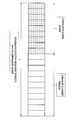
図9は、PMCH及びPMCHにマッピングされるMTCHの例を説明するための説明図である。図9を参照すると、図8を参照して説明した20個のMBSFNサブフレームの4つのセットが示されている。即ち、4つのCSA期間(即ち、CSA期間1~4)にわたる80個のMBSFNサブフレームが示されている。この例では、CSA期間(32無線フレーム)内の20個のMBSFNサブフレームのうちの、1番目のサブフレームから7番目のサブフレームまでが、PMCH1に割り当てられている。また、8番目のサブフレームから11番目のサブフレームまでが、PMCH2に、12番目のサブフレームから15番目のサブフレームまでが、PMCH3に、16番目のサブフレームから20番目のサブフレームまでが、PMCH4に、割り当てられている。また、PMCH1には、論理チャネル1及び2(即ち、MTCH1及び2)がマッピングされる。また、PMCH2には論理チャネル3(即ち、MTCH3)がマッピングされ、PMCH3には論理チャネル4(即ち、MTCH4)がマッピングされ、PMCH4には論理チャネル5(即ち、MTCH5)がマッピングされる。PMCH1に注目すると、PMCH1のMSPは64無線フレームであり、PMCH1では2つのCSA期間ごとにMSIが送信される。CSA期間1及び2では、PMCH1に割り当てられたMBSFNサブフレームのうちの、1番目のサブフレームから9番目までのサブフレームに、論理チャネル1(即ち、MTCH1)が配置される。また、10番目から13番目のサブフレームに、論理チャネル2(即ち、MTCH2)が配置される。14番目のサブフレームには、いずれの論理チャネル(MTCH)も配置されない。また、CSA期間3及び4では、PMCH1に割り当てられたMBSFNサブフレームのうちの、1番目のサブフレームから8番目までのサブフレームに、論理チャネル1が配置される。また、9番目から12番目のサブフレームに、論理チャネル2が配置される。なお、13番目のサブフレーム及び14番目のサブフレームには、いずれの論理チャネル(MTCH)も配置されない。なお、図9に示されるように、MBSFNサブフレームには、MCCHも配置される。
FIG. 9 is an explanatory diagram for explaining an example of MTCH mapped to PMCH and PMCH. Referring to FIG. 9, four sets of 20 MBSFN subframes described with reference to FIG. 8 are shown. That is, 80 MBSFN subframes over four CSA periods (ie, CSA periods 1 to 4) are shown. In this example, among the 20 MBSFN subframes in the CSA period (32 radio frames), the first to seventh subframes are allocated to PMCH1. Also, from the 8th subframe to the 11th subframe, PMCH2, from the 12th subframe to the 15th subframe, to PMCH3, from the 16th subframe to the 20th subframe, Assigned to PMCH4. Also, logical channels 1 and 2 (that is, MTCH1 and 2) are mapped to PMCH1. Further, logical channel 3 (that is, MTCH3) is mapped to PMCH2, logical channel 4 (that is, MTCH4) is mapped to PMCH3, and logical channel 5 (that is, MTCH5) is mapped to PMCH4. Paying attention to PMCH1, the MSP of PMCH1 is 64 radio frames, and MSI is transmitted every two CSA periods in PMCH1. In CSA periods 1 and 2, logical channel 1 (that is, MTCH1) is arranged in the first through ninth subframes of the MBSFN subframes allocated to PMCH1. Further, logical channel 2 (that is, MTCH2) is arranged in the 10th to 13th subframes. No logical channel (MTCH) is arranged in the 14th subframe. Further, in the CSA periods 3 and 4, the logical channel 1 is arranged in the first to eighth subframes of the MBSFN subframes allocated to PMCH1. In addition, the logical channel 2 is arranged in the ninth to twelfth subframes. Note that no logical channel (MTCH) is arranged in the 13th subframe and the 14th subframe. As shown in FIG. 9, MCCH is also arranged in the MBSFN subframe.
(MCCHについての変更の通知)
MCCHの情報に変更がある場合には、MCCHの情報の変更が、MBSFNサブフレームの非MBSFN領域内のPDCCH(Physical Downlink Control Channel)上で送信されるDCI(Downlink Control Information)の中で全ての端末装置に通知される。具体的には、上記DCIには、MCCH変更通知インジケータ(MCCH Change Notification Indicator)が含まれる。当該MCCH変更通知インジケータは、MBSFNエリアにそれぞれ対応する8ビットのビットマップである。なお、この通知には、MBMS RNTI(Radio Network Temporary Identity)、即ちM-RNTIが使用される。 (Notification of change about MCCH)
When there is a change in the MCCH information, the change in the MCCH information is all the DCI (Downlink Control Information) transmitted in the PDCCH (Physical Downlink Control Channel) in the non-MBSFN area of the MBSFN subframe. It is notified to the terminal device. Specifically, the DCI includes an MCCH change notification indicator. The MCCH change notification indicator is an 8-bit bitmap corresponding to each MBSFN area. For this notification, MBMS RNTI (Radio Network Temporary Identity), that is, M-RNTI is used.
まず、MCCH変更期間(MCCH modification period)に、MCCHの情報の変更の通知が行われ、その次のMCCH変更期間に、変更された情報の通知が行われる。以下、この点について、図10を参照して具体例を説明する。
First, an MCCH information change notification is made in the MCCH modification period, and the changed information is notified in the next MCCH change period. Hereinafter, a specific example of this point will be described with reference to FIG.
図10は、MCCHの情報の変更に関する通知のタイミングの例を説明するための説明図である。図10を参照すると、第1のMCCH変更期間(n)とそれに続く第2のMCCHの変更期間(n+1)とが示されている。このように、第1のMCCH変更期間(n)において、MCCHの情報の変更の通知が行われ、その後、第2のMCCH変更期間(n+1)において、変更された情報の通知が行われる。なお、端末装置のモビリティの確保のために、変更された情報は、最初のMCCHだけではなく、その後のMCCHでも送信される。MCCHの情報は、比較的長時間をかけて変更される。
FIG. 10 is an explanatory diagram for explaining an example of a notification timing related to a change in MCCH information. Referring to FIG. 10, a first MCCH change period (n) followed by a second MCCH change period (n + 1) is shown. As described above, the change notification of the MCCH information is performed in the first MCCH change period (n), and then the changed information is notified in the second MCCH change period (n + 1). In addition, in order to ensure the mobility of the terminal device, the changed information is transmitted not only in the first MCCH but also in the subsequent MCCH. MCCH information is changed over a relatively long time.
(MBSFNのためのシステム構成)
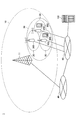
図11を参照して、MBSFNをサポートするLTEネットワークの構成の例を説明する。図11は、MBSFNをサポートするLTEネットワークの構成の一例を説明するための説明図である。図11を参照すると、LTEネットワークは、MCE(Multi-cell/Multicast Coordination Entity)、BM-SC(Broadcast/Multicast Service Center)、MBMS GW(gateway)及びMME(Mobility Management Entity)などを含む。これらのノードは、論理ノードである。MCEは、MBSNFエリアに属するセルのeNB(evolved Node B)に、同一の無線リソースで同一のデータを送信させる。具体的には、例えば、MCEは、MBSNFエリア内のMBSNFに関するスケジューリングを行う。BM-SCは、コンテンツプロバイダの認証、課金、及びコアネットワーク内のデータフロー制御などを行う。MBMS-GWは、BM-SCからeNBまでのマルチキャストIPパケットの転送、及びMME経由のセッション制御信号の処理などを行う。MMEは、NAS(Non-Access Stratum)信号の処理を行う。 (System configuration for MBSFN)
An example of the configuration of an LTE network that supports MBSFN will be described with reference to FIG. FIG. 11 is an explanatory diagram for explaining an example of a configuration of an LTE network that supports MBSFN. Referring to FIG. 11, the LTE network includes MCE (Multi-cell / Multicast Coordination Entity), BM-SC (Broadcast / Multicast Service Center), MBMS GW (gateway), MME (Mobility Management Entity), and the like. These nodes are logical nodes. The MCE causes the eNB (evolved Node B) of the cell belonging to the MBSNF area to transmit the same data using the same radio resource. Specifically, for example, the MCE performs scheduling related to the MBSNF in the MBSNF area. The BM-SC performs content provider authentication, billing, data flow control in the core network, and the like. The MBMS-GW performs multicast IP packet transfer from the BM-SC to the eNB, processing of session control signals via the MME, and the like. The MME processes a NAS (Non-Access Stratum) signal.
なお、1つのMCEが複数のeNBに対応する例を説明したが、MCEは係る例に限定されない。例えば、各eNBがMCEを備えてもよい。
Although an example in which one MCE corresponds to a plurality of eNBs has been described, the MCE is not limited to such an example. For example, each eNB may include an MCE.
(カウンティング手続き)
MBSFNでは、MBMSカウンティング手続きを通じて、MBMSサービスへの関心の情報が収集される。以下、図12を参照して、MBMSカウンティング手続きを説明する。 (Counting procedure)
In MBSFN, information of interest in the MBMS service is collected through an MBMS counting procedure. Hereinafter, the MBMS counting procedure will be described with reference to FIG.
MBSFNでは、MBMSカウンティング手続きを通じて、MBMSサービスへの関心の情報が収集される。以下、図12を参照して、MBMSカウンティング手続きを説明する。 (Counting procedure)
In MBSFN, information of interest in the MBMS service is collected through an MBMS counting procedure. Hereinafter, the MBMS counting procedure will be described with reference to FIG.
図12は、MBMSカウンティング手続きの例を説明するための説明図である。図12を参照すると、まず、MCCHの情報が変更されたとき、及び端末装置がMBSFNエリアに入ったときに、端末装置は、MBSFNエリアコンフィギュレーションメッセージとともに、MBMSカウンティング要求メッセージを受信する。そして、端末装置がRRC接続モードである場合に、端末装置が関心を有するMBMSサービスが、MBMSカウンティング要求のリストに含まれていれば、端末装置は、当該MBMSサービスの識別子を含むMBMSカウンティング応答メッセージ(MBMS Counting Response message)をネットワークへ送信する。これにより、MBMSサービスごとに、MBMSサービスを受信し又はサービスに関心を有する端末装置の数をカウントすることが可能になる。そのため、カウンティングの結果に応じてMBMSサービスの開始及び終了を制御することが可能になる。
FIG. 12 is an explanatory diagram for explaining an example of the MBMS counting procedure. Referring to FIG. 12, first, when the MCCH information is changed and when the terminal device enters the MBSFN area, the terminal device receives an MBMS counting request message together with the MBSFN area configuration message. When the terminal device is in the RRC connection mode, if the MBMS service that the terminal device is interested in is included in the list of MBMS counting requests, the terminal device sends an MBMS counting response message including the identifier of the MBMS service. (MBMS Counting Response message) is sent to the network. Thus, for each MBMS service, it is possible to count the number of terminal devices that receive the MBMS service or are interested in the service. Therefore, it is possible to control the start and end of the MBMS service according to the counting result.
(端末の動作)
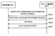
端末装置は、SIB13を受信し、MCCHが配置されるサブフレームなどを特定する。そして、端末装置は、当該サブフレームで、MCCHの情報としてMBSFNエリアコンフィギュレーションメッセージを受信し、所望のMBMSセッションのMTCHがマッピングされるPMCHを特定する。その後、端末装置は、上記MTCHがマッピングされる上記PMCHのMSIを受信し、上記MTCHが配置されるサブフレームを特定する。そして、端末装置は、当該サブフレームで、上記MTCHのデータ(即ち、上記所望のMBMSセッションのデータ)を受信する。このような動作によれば、端末装置は、必要最小限のサブフレームのみでの受信を行い、その他のサブフレームでスリープすることができる。そのため、端末装置の消費電力が抑えられる。 (Device operation)
The terminal device receives theSIB 13 and specifies a subframe in which the MCCH is arranged. Then, the terminal apparatus receives the MBSFN area configuration message as MCCH information in the subframe, and specifies the PMCH to which the MTCH of the desired MBMS session is mapped. Thereafter, the terminal apparatus receives the MSI of the PMCH to which the MTCH is mapped, and specifies a subframe in which the MTCH is arranged. Then, the terminal apparatus receives the MTCH data (that is, the desired MBMS session data) in the subframe. According to such an operation, the terminal apparatus can perform reception using only the minimum necessary subframe and can sleep in other subframes. Therefore, power consumption of the terminal device can be suppressed.
端末装置は、SIB13を受信し、MCCHが配置されるサブフレームなどを特定する。そして、端末装置は、当該サブフレームで、MCCHの情報としてMBSFNエリアコンフィギュレーションメッセージを受信し、所望のMBMSセッションのMTCHがマッピングされるPMCHを特定する。その後、端末装置は、上記MTCHがマッピングされる上記PMCHのMSIを受信し、上記MTCHが配置されるサブフレームを特定する。そして、端末装置は、当該サブフレームで、上記MTCHのデータ(即ち、上記所望のMBMSセッションのデータ)を受信する。このような動作によれば、端末装置は、必要最小限のサブフレームのみでの受信を行い、その他のサブフレームでスリープすることができる。そのため、端末装置の消費電力が抑えられる。 (Device operation)
The terminal device receives the
(HeNBのアクセス制御)
フェムトセルのようなCSGセルでは、端末のアクセス権(CSG UEであるか又は非CSG UEであるか)に応じて、当該端末に提供されるサービスの品質及び/又は種類が変わり得る。 (HeNB access control)
In a CSG cell such as a femto cell, the quality and / or type of service provided to the terminal may change depending on the access right of the terminal (whether it is a CSG UE or a non-CSG UE).
ホームeNB(HeNB)は、CSG UEのみがセルへのアクセスを行うことができるクローズドアクセスモードに加えて、アクセス制御が行われないオープンアクセスモードで動作することができる。さらに、HeNBは、非CSG UEもセルへのアクセスを行うことができるが、非CSG UEと CSG UEとが区別されるハイブリッドアクセスモードでも動作することができる。
The home eNB (HeNB) can operate in an open access mode in which access control is not performed in addition to a closed access mode in which only a CSG UE can access a cell. Further, the HeNB can also access a cell by a non-CSG UE, but can also operate in a hybrid access mode in which a non-CSG UE and a CSG UE are distinguished.
<<2.通信システムの概略的な構成>>
続いて、図13を参照して、本開示の実施形態に係る通信システム1の概略的な構成を説明する。図13は、本実施形態に係る通信システム1の概略的な構成の一例を示す説明図である。図13を参照すると、通信システム1は、マクロ基地局11、制御装置100、スモール基地局200及び端末装置300を含む。通信システム1は、例えば、LTE、LTE-Advanced、又はこれらに準ずる通信規格に準拠したシステムである。 << 2. Schematic configuration of communication system >>
Next, a schematic configuration of thecommunication system 1 according to the embodiment of the present disclosure will be described with reference to FIG. FIG. 13 is an explanatory diagram illustrating an example of a schematic configuration of the communication system 1 according to the present embodiment. Referring to FIG. 13, the communication system 1 includes a macro base station 11, a control device 100, a small base station 200, and a terminal device 300. The communication system 1 is, for example, a system that conforms to LTE, LTE-Advanced, or a communication standard based on these.
続いて、図13を参照して、本開示の実施形態に係る通信システム1の概略的な構成を説明する。図13は、本実施形態に係る通信システム1の概略的な構成の一例を示す説明図である。図13を参照すると、通信システム1は、マクロ基地局11、制御装置100、スモール基地局200及び端末装置300を含む。通信システム1は、例えば、LTE、LTE-Advanced、又はこれらに準ずる通信規格に準拠したシステムである。 << 2. Schematic configuration of communication system >>
Next, a schematic configuration of the
マクロ基地局11は、マクロセル10内に位置する端末装置との無線通信を行う。マクロ基地局11は、コアネットワーク40に接続されている。
The macro base station 11 performs wireless communication with a terminal device located in the macro cell 10. The macro base station 11 is connected to the core network 40.
スモール基地局200は、スモールセル20内に位置する端末装置との無線通信を行う。スモールセル20は、例えば、マクロセル10と一部又は全体で重なる。また、複数のスモールセル20は、同一のMBSNFエリア30に属し、MBSNFエリア30では、複数のスモール基地局200が、MBSNFサブフレーム内で、同一の無線リソースで同一の信号を送信する。なお、例えば、スモールセル20は、フェムトセルであり、スモール基地局200は、インターネット50に接続されている。
The small base station 200 performs wireless communication with a terminal device located in the small cell 20. For example, the small cell 20 partially or entirely overlaps with the macro cell 10. The plurality of small cells 20 belong to the same MBSNF area 30, and in the MBSNF area 30, the plurality of small base stations 200 transmit the same signal using the same radio resource in the MBSNF subframe. For example, the small cell 20 is a femto cell, and the small base station 200 is connected to the Internet 50.
制御装置100は、上記複数のスモール基地局200にとってのMCEとして動作する。例えば、制御装置100は、MBMS-GWとしても動作する。制御装置100は、例えば、インターネット50に接続され、インターネット50を介してスモール基地局200と通信する。また、制御装置100は、インターネット50を介して、コアネットワーク40内に位置するコアネットワークノード(例えば、MMEなど)、及び/又はマクロ基地局11と通信し得る。
The control device 100 operates as an MCE for the plurality of small base stations 200. For example, the control device 100 also operates as an MBMS-GW. For example, the control device 100 is connected to the Internet 50 and communicates with the small base station 200 via the Internet 50. In addition, the control device 100 can communicate with a core network node (for example, an MME) located in the core network 40 and / or the macro base station 11 via the Internet 50.
端末装置300は、基地局との無線通信を行う。例えば、端末装置300は、マクロセル10内に位置する場合に、マクロ基地局11との無線通信を行う。また、端末装置300は、スモールセル20内に位置する場合に、スモール基地局200との無線通信を行う。
The terminal device 300 performs wireless communication with the base station. For example, the terminal device 300 performs wireless communication with the macro base station 11 when located in the macro cell 10. Also, the terminal device 300 performs wireless communication with the small base station 200 when located in the small cell 20.
以上、本開示の実施形態に係る通信システム1の概略的な構成を説明した。本開示の実施形態によれば、スモール基地局200は、特定の端末グループ用のMBSFNサブフレームに配置されるマルチキャストチャネルの構成を示すチャネル構成情報を上記特定の端末グループに通知する。これにより、例えば、特定の端末グループへのマルチキャストを行うことが可能になる。なお、端末装置300は、上記特定の端末グループに属する。また、例えば、上記特定の端末グループは、CSGである。
The schematic configuration of the communication system 1 according to the embodiment of the present disclosure has been described above. According to the embodiment of the present disclosure, the small base station 200 notifies the specific terminal group of channel configuration information indicating the configuration of the multicast channel arranged in the MBSFN subframe for the specific terminal group. Thereby, for example, it becomes possible to perform multicast to a specific terminal group. Note that the terminal device 300 belongs to the specific terminal group. For example, the specific terminal group is a CSG.
<<3.第1の実施形態>>
続いて、図14~図26を参照して、本開示の第1の実施形態を説明する。上述したように、本開示の実施形態によれば、スモール基地局200は、特定の端末グループ用のMBSFNサブフレームに配置されるマルチキャストチャネルの構成を示すチャネル構成情報を上記特定の端末グループに通知する。とりわけ第1の実施形態では、当該マルチキャストチャネルは、MCCHである。即ち、第1の実施形態によれば、スモール基地局200は、特定の端末グループ用のMBSNFサブフレームに配置されるMCCHの構成を示すチャネル構成情報を上記特定の端末グループに通知する。 << 3. First Embodiment >>
Subsequently, a first embodiment of the present disclosure will be described with reference to FIGS. As described above, according to the embodiment of the present disclosure, thesmall base station 200 notifies the specific terminal group of channel configuration information indicating the configuration of the multicast channel arranged in the MBSFN subframe for the specific terminal group. To do. In particular, in the first embodiment, the multicast channel is MCCH. That is, according to the first embodiment, the small base station 200 notifies the specific terminal group of channel configuration information indicating the configuration of the MCCH arranged in the MBSNF subframe for the specific terminal group.
続いて、図14~図26を参照して、本開示の第1の実施形態を説明する。上述したように、本開示の実施形態によれば、スモール基地局200は、特定の端末グループ用のMBSFNサブフレームに配置されるマルチキャストチャネルの構成を示すチャネル構成情報を上記特定の端末グループに通知する。とりわけ第1の実施形態では、当該マルチキャストチャネルは、MCCHである。即ち、第1の実施形態によれば、スモール基地局200は、特定の端末グループ用のMBSNFサブフレームに配置されるMCCHの構成を示すチャネル構成情報を上記特定の端末グループに通知する。 << 3. First Embodiment >>
Subsequently, a first embodiment of the present disclosure will be described with reference to FIGS. As described above, according to the embodiment of the present disclosure, the
<3.1.制御装置の構成>
まず、図14~図17を参照して、第1の実施形態に係る制御装置100-1の構成を説明する。図14は、第1の実施形態に係る制御装置100-1の構成の一例を示すブロック図である。図14を参照すると、制御装置100-1は、通信部110、記憶部120及び処理部130を備える。 <3.1. Configuration of control device>
First, the configuration of the control device 100-1 according to the first embodiment will be described with reference to FIGS. FIG. 14 is a block diagram illustrating an example of the configuration of the control device 100-1 according to the first embodiment. Referring to FIG. 14, the control device 100-1 includes acommunication unit 110, a storage unit 120, and a processing unit 130.
まず、図14~図17を参照して、第1の実施形態に係る制御装置100-1の構成を説明する。図14は、第1の実施形態に係る制御装置100-1の構成の一例を示すブロック図である。図14を参照すると、制御装置100-1は、通信部110、記憶部120及び処理部130を備える。 <3.1. Configuration of control device>
First, the configuration of the control device 100-1 according to the first embodiment will be described with reference to FIGS. FIG. 14 is a block diagram illustrating an example of the configuration of the control device 100-1 according to the first embodiment. Referring to FIG. 14, the control device 100-1 includes a
(通信部110)
通信部110は、他の装置と通信する。例えば、通信部110は、スモール基地局200-1と通信する。より具体的には、例えば、通信部110は、インターネット50を介してスモール基地局200-1と通信する。また、通信部110は、インターネット50を介して、コアネットワーク40内に位置するコアネットワークノード(例えば、MMEなど)、及び/又はマクロ基地局11と通信し得る。 (Communication unit 110)
Thecommunication unit 110 communicates with other devices. For example, the communication unit 110 communicates with the small base station 200-1. More specifically, for example, the communication unit 110 communicates with the small base station 200-1 via the Internet 50. In addition, the communication unit 110 can communicate with a core network node (for example, MME or the like) located in the core network 40 and / or the macro base station 11 via the Internet 50.
通信部110は、他の装置と通信する。例えば、通信部110は、スモール基地局200-1と通信する。より具体的には、例えば、通信部110は、インターネット50を介してスモール基地局200-1と通信する。また、通信部110は、インターネット50を介して、コアネットワーク40内に位置するコアネットワークノード(例えば、MMEなど)、及び/又はマクロ基地局11と通信し得る。 (Communication unit 110)
The
(記憶部120)
記憶部120は、制御装置100-1の動作のためのプログラム及びデータを一時的にまたは恒久的に記憶する。 (Storage unit 120)
Thestorage unit 120 temporarily or permanently stores a program and data for the operation of the control device 100-1.
記憶部120は、制御装置100-1の動作のためのプログラム及びデータを一時的にまたは恒久的に記憶する。 (Storage unit 120)
The
(処理部130)
処理部130は、制御装置100-1の様々な機能を提供する。処理部130は、決定部131及び通知部133を含む。 (Processing unit 130)
Theprocessing unit 130 provides various functions of the control device 100-1. The processing unit 130 includes a determination unit 131 and a notification unit 133.
処理部130は、制御装置100-1の様々な機能を提供する。処理部130は、決定部131及び通知部133を含む。 (Processing unit 130)
The
(決定部131)
-MBSFNサブフレームの決定
決定部131は、例えば、MBSFNサブフレームを決定する。 (Determining unit 131)
-Determination of MBSFN subframe Thedetermination unit 131 determines, for example, an MBSFN subframe.
-MBSFNサブフレームの決定
決定部131は、例えば、MBSFNサブフレームを決定する。 (Determining unit 131)
-Determination of MBSFN subframe The
具体的には、例えば、決定部131は、特定の端末グループ用のMBSFNサブフレーム(以下、「グループMBSFNサブフレーム」と呼ぶ)を決定する。当該特定の端末グループは、例えばCSGである。また、例えば、決定部131は、通常のMBSFNサブフレーム(即ち、全ての端末装置用のMBSFNサブフレーム)も決定する。以下、この点について、図15を参照して具体例を説明する。
Specifically, for example, the determination unit 131 determines an MBSFN subframe for a specific terminal group (hereinafter referred to as “group MBSFN subframe”). The specific terminal group is, for example, CSG. For example, the determination unit 131 also determines normal MBSFN subframes (that is, MBSFN subframes for all terminal apparatuses). Hereinafter, a specific example of this point will be described with reference to FIG.
図15は、グループMBSFNサブフレームの例を説明するための説明図である。図15を参照すると、CSA(Common Subframe Allocation)期間内の20個のMBSFNサブフレームが示されている。決定部131は、例えば、図8を参照して説明したような手法で、32無線フレームの中の20個のサブフレームをMBSFNサブフレームとして決定する。そして、決定部131は、当該20個のMBSFNサブフレームのうちの11個のMBSFNサブフレームを、通常のMBSFNサブフレーム(即ち、全ての端末装置用のMBSFNサブフレーム)として決定する。また、決定部131は、当該20個のMBSFNサブフレームのうちの残りの9個のMBSFNサブフレームを、グループMBSFNサブフレームとして決定する。
FIG. 15 is an explanatory diagram for explaining an example of a group MBSFN subframe. Referring to FIG. 15, 20 MBSFN subframes within a CSA (Common Subframe Allocation) period are shown. The determination unit 131 determines, for example, 20 subframes in the 32 radio frames as MBSFN subframes by the method described with reference to FIG. Then, the determination unit 131 determines 11 MBSFN subframes out of the 20 MBSFN subframes as normal MBSFN subframes (that is, MBSFN subframes for all terminal apparatuses). Also, the determination unit 131 determines the remaining 9 MBSFN subframes among the 20 MBSFN subframes as a group MBSFN subframe.
なお、MBSFNサブフレームが決定され、当該MBSFNサブフレームの一部が通常のサブフレームとして決定され、当該MBSFNサブフレームの残りがグループMBSFNサブフレームとして決定されるという一例を説明したが、グループMBSFNサブフレームの決定の手法は係る例に限定されない。例えば、グループMBSFNサブフレームは、通常のMBSFNサブフレームから独立して決定されてもよい。具体的には、例えば、決定部131は、グループMBSFNサブフレームのための無線フレーム割当て期間、無線フレーム割当てオフセット及びサブフレーム割当て(並びにCSA期間)を決定してもよい。この場合に、決定部131は、通常のMBSFNサブフレームのための無線フレーム割当て期間、無線フレーム割当てオフセット及びサブフレーム割当て(並びにCSA期間)をさらに決定してもよい。あるいは、上記特定の端末グループのみに対するマルチキャストが行われ、決定部131は、通常のMBSFNサブフレームを決定せず、グループMBSFNサブフレームのみを決定してもよい。
An example has been described in which an MBSFN subframe is determined, a part of the MBSFN subframe is determined as a normal subframe, and the rest of the MBSFN subframe is determined as a group MBSFN subframe. The method for determining the frame is not limited to this example. For example, the group MBSFN subframe may be determined independently of the normal MBSFN subframe. Specifically, for example, the determination unit 131 may determine a radio frame allocation period, a radio frame allocation offset, and a subframe allocation (and CSA period) for the group MBSFN subframe. In this case, the determination unit 131 may further determine a radio frame allocation period, a radio frame allocation offset, and a subframe allocation (and a CSA period) for a normal MBSFN subframe. Alternatively, multicasting is performed only on the specific terminal group, and the determination unit 131 may determine only the group MBSFN subframe without determining the normal MBSFN subframe.
-マルチキャストチャネルの配置の決定
決定部131は、MBSFNサブフレームにおけるマルチキャストチャネルの配置を決定する。 -Determination of Multicast Channel Arrangement Thedetermination unit 131 determines the arrangement of the multicast channel in the MBSFN subframe.
決定部131は、MBSFNサブフレームにおけるマルチキャストチャネルの配置を決定する。 -Determination of Multicast Channel Arrangement The
例えば、決定部131は、上記グループMBSFNサブフレームにおけるマルチキャストチャネルの配置を決定する。また、例えば、決定部131は、上記通常のMBSFNサブフレームにおけるマルチキャストチャネルの配置を決定する。
For example, the determination unit 131 determines the arrangement of the multicast channel in the group MBSFN subframe. For example, the determination unit 131 determines the arrangement of the multicast channel in the normal MBSFN subframe.
--PMCH
例えば、上記マルチキャストチャネルは、PMCHである。即ち、決定部131は、MBSFNサブフレームにおけるPMCHの配置を決定する。換言すると、決定部131は、MBSFNサブフレームをPMCHに割り当てる。 --PMCH
For example, the multicast channel is PMCH. That is, thedetermination unit 131 determines the arrangement of PMCHs in the MBSFN subframe. In other words, the determination unit 131 allocates the MBSFN subframe to the PMCH.
例えば、上記マルチキャストチャネルは、PMCHである。即ち、決定部131は、MBSFNサブフレームにおけるPMCHの配置を決定する。換言すると、決定部131は、MBSFNサブフレームをPMCHに割り当てる。 --PMCH
For example, the multicast channel is PMCH. That is, the
具体的には、例えば、決定部131は、上記グループMBSFNサブフレームにおけるPMCHの配置を決定する。また、例えば、決定部131は、上記通常のMBSFNサブフレームにおけるPMCHの配置を決定する。以下、この点について図16を参照して具体例を説明する。
Specifically, for example, the determination unit 131 determines the arrangement of PMCHs in the group MBSFN subframe. For example, the determination unit 131 determines the arrangement of PMCHs in the normal MBSFN subframe. Hereinafter, a specific example of this point will be described with reference to FIG.
図16は、MBSFNサブフレームにおけるPMCHの配置の例を説明するための説明図である。図16を参照すると、図15を参照して説明した20個のMBSFNサブフレームが示されている。上述したように、11個のMBSFNサブフレームが、通常のMBSFNサブフレームであり、9個のMBSFNサブフレームが、グループMBSFNサブフレームである。この例では、上記通常のMBSFNサブフレームのうちの7個のMBSFNサブフレームにPMCH1が配置され、上記通常のMBSFNサブフレームのうちの4個のMBSFNサブフレームにPMCH2が配置される。換言すると、上記7個のMBSFNサブフレームがPMCH1に割り当てられ、上記4個のMBSFNサブフレームがPMCH2に割り当てられる。また、上記グループMBSFNサブフレーム全体にPMCH3が配置される。換言すると、上記グループMBSFNサブフレーム全てがPMCH3に割り当てられる。PMCH1及びPMCH2は、通常のPMCH(全ての端末装置用のPMCH)であり、PMCH3は、上記特定の端末グループ用のPMCHであると言える。
FIG. 16 is an explanatory diagram for explaining an example of arrangement of PMCH in the MBSFN subframe. Referring to FIG. 16, 20 MBSFN subframes described with reference to FIG. 15 are illustrated. As described above, 11 MBSFN subframes are normal MBSFN subframes, and 9 MBSFN subframes are group MBSFN subframes. In this example, PMCH1 is arranged in seven MBSFN subframes out of the normal MBSFN subframes, and PMCH2 is arranged in four MBSFN subframes out of the normal MBSFN subframes. In other words, the seven MBSFN subframes are allocated to PMCH1, and the four MBSFN subframes are allocated to PMCH2. Also, PMCH3 is arranged in the entire group MBSFN subframe. In other words, all the group MBSFN subframes are allocated to PMCH3. PMCH1 and PMCH2 are normal PMCHs (PMCHs for all terminal devices), and PMCH3 can be said to be a PMCH for the specific terminal group.
--MTCH
例えば、上記マルチキャストチャネルは、MTCHである。即ち、決定部131は、MBSFNサブフレームにおける各MTCHの配置を決定する。換言すると、決定部131は、MBSFNサブフレームを各MTCHに割り当てる。 --MTCH
For example, the multicast channel is MTCH. That is, thedetermination unit 131 determines the arrangement of each MTCH in the MBSFN subframe. In other words, the determination unit 131 allocates the MBSFN subframe to each MTCH.
例えば、上記マルチキャストチャネルは、MTCHである。即ち、決定部131は、MBSFNサブフレームにおける各MTCHの配置を決定する。換言すると、決定部131は、MBSFNサブフレームを各MTCHに割り当てる。 --MTCH
For example, the multicast channel is MTCH. That is, the
具体的には、例えば、決定部131は、上記グループMBSFNサブフレームにおけるMTCHの配置を決定する。また、例えば、決定部131は、上記通常のMBSFNサブフレームにおけるMTCHの配置を決定する。以下、この点について図17を参照して具体例を説明する。
Specifically, for example, the determination unit 131 determines the arrangement of the MTCH in the group MBSFN subframe. For example, the determination unit 131 determines the arrangement of the MTCH in the normal MBSFN subframe. Hereinafter, a specific example of this point will be described with reference to FIG.
図17は、MBSFNサブフレームにおけるMTCHの配置の例を説明するための説明図である。図17を参照すると、図15及び図16を参照して説明した20個のMBSFNサブフレームの4つのセットが示されている。即ち、4つのCSA期間(即ち、CSA期間1~4)にわたる80個のMBSFNサブフレームが示されている。また、図16を参照して説明したように、通常のMBSFNサブフレームにPMCH1及びPMCH2が配置され、グループMBSFNサブフレームにPMCH3が配置される。また、PMCH1には、論理チャネル1及び2(即ち、MTCH1及び2)がマッピングされ、PMCH2には、論理チャネル3(即ち、MTCH3)がマッピングされる。また、特定の端末グループ用のPMCHであるPMCH3には、論理チャネル4及び5(即ち、MTCH4及び5)がマッピングされる。PMCH3に注目すると、PMCH3のMSPは64無線フレームであり、PMCH3では2つのCSA期間(64無線フレーム)ごとにMSIが送信される。CSA期間1及び2では、PMCH3が配置されるグループMBSFNサブフレームのうちの1番目のサブフレームから6番目までのサブフレームに、論理チャネル4が配置され、上記グループMBSFNサブフレームのうちの7番目から15番目のサブフレームに、論理チャネル5が配置される。即ち、1番目のサブフレームから6番目までのサブフレームが論理チャネル4に割り当てられ、7番目から15番目のサブフレームが論理チャネル5に割り当てられる。なお、16番目のサブフレームから18番目のサブフレームには、いずれの論理チャネル(MTCH)も配置されない。CSA期間3及び4では、PMCH3が配置されるグループMBSFNサブフレームのうちの1番目のサブフレームから7番目までのサブフレームに、論理チャネル4が配置され、上記グループMBSFNサブフレームのうちの8番目から12番目のサブフレームに、論理チャネル5が配置される。即ち、1番目のサブフレームから7番目までのサブフレームが論理チャネル4に割り当てられ、8番目から12番目のサブフレームが論理チャネル5に割り当てられる。なお、13番目のサブフレームから18番目のサブフレームは、いずれの論理チャネル(MTCH)も配置されない。
FIG. 17 is an explanatory diagram for explaining an example of arrangement of MTCH in the MBSFN subframe. Referring to FIG. 17, four sets of 20 MBSFN subframes described with reference to FIGS. 15 and 16 are shown. That is, 80 MBSFN subframes over four CSA periods (ie, CSA periods 1 to 4) are shown. Also, as described with reference to FIG. 16, PMCH1 and PMCH2 are arranged in a normal MBSFN subframe, and PMCH3 is arranged in a group MBSFN subframe. Further, logical channels 1 and 2 (that is, MTCH1 and 2) are mapped to PMCH1, and logical channel 3 (that is, MTCH3) is mapped to PMCH2. Also, logical channels 4 and 5 (that is, MTCHs 4 and 5) are mapped to PMCH3, which is a PMCH for a specific terminal group. When paying attention to PMCH3, the MSP of PMCH3 is 64 radio frames, and MSI is transmitted every two CSA periods (64 radio frames) in PMCH3. In CSA periods 1 and 2, logical channel 4 is arranged in the first to sixth subframes of the group MBSFN subframe in which PMCH3 is arranged, and the seventh of the group MBSFN subframes. The logical channel 5 is arranged in the fifteenth subframe. That is, the first to sixth subframes are assigned to the logical channel 4, and the seventh to fifteenth subframes are assigned to the logical channel 5. Note that no logical channel (MTCH) is arranged in the 16th to 18th subframes. In CSA periods 3 and 4, logical channel 4 is arranged in the first to seventh subframes of the group MBSFN subframe in which PMCH3 is arranged, and the eighth of the group MBSFN subframes. The logical channel 5 is arranged in the 12th subframe from the beginning. That is, the first to seventh subframes are assigned to the logical channel 4, and the eighth to twelfth subframes are assigned to the logical channel 5. Note that no logical channel (MTCH) is arranged in the 13th to 18th subframes.
--MCCH
例えば、上記マルチキャストチャネルは、MCCHである。即ち、決定部131は、MBSFNサブフレームにおける各MCCHの配置を決定する。 --- MCCH
For example, the multicast channel is MCCH. That is, thedetermination unit 131 determines the arrangement of each MCCH in the MBSFN subframe.
例えば、上記マルチキャストチャネルは、MCCHである。即ち、決定部131は、MBSFNサブフレームにおける各MCCHの配置を決定する。 --- MCCH
For example, the multicast channel is MCCH. That is, the
具体的には、例えば、決定部131は、上記グループMBSFNサブフレームにおけるMCCHの配置を決定する。また、例えば、決定部131は、上記通常のMBSFNサブフレームにおけるMCCHの配置を決定する。
Specifically, for example, the determination unit 131 determines the MCCH arrangement in the group MBSFN subframe. For example, the determination unit 131 determines the MCCH arrangement in the normal MBSFN subframe.
(通知部133)
-MBSFNサブフレームの通知
通知部133は、例えば、MBSFNサブフレームをスモール基地局200-1に通知する。例えば、通知部133は、上記グループMBSFNサブフレームをスモール基地局200-1に通知する。また、例えば、通知部133は、上記通常のMBSFNサブフレームをスモール基地局200-1に通知する。 (Notification part 133)
-Notification of MBSFN subframe Thenotification unit 133 notifies the small base station 200-1 of, for example, an MBSFN subframe. For example, the notification unit 133 notifies the small base station 200-1 of the group MBSFN subframe. For example, the notification unit 133 notifies the small base station 200-1 of the normal MBSFN subframe.
-MBSFNサブフレームの通知
通知部133は、例えば、MBSFNサブフレームをスモール基地局200-1に通知する。例えば、通知部133は、上記グループMBSFNサブフレームをスモール基地局200-1に通知する。また、例えば、通知部133は、上記通常のMBSFNサブフレームをスモール基地局200-1に通知する。 (Notification part 133)
-Notification of MBSFN subframe The
具体的には、例えば、通知部133は、スモール基地局200-1へ送信されるMBMSスケジューリング情報メッセージの中で、MBSFNサブフレームをスモール基地局200-1に通知する。例えば、上記MBMSスケジューリング情報メッセージは、無線フレーム割当て期間、無線フレーム割当てオフセット及びサブフレーム割当てと、CSA期間とを含む。これにより、CSA期間内のMBSFNサブフレームが示される。さらに、例えば、上記MBMSスケジューリング情報メッセージは、上記MBSFNサブフレームに含まれる通常のMBSFNサブフレームとグループMBSFNサブフレームとを区別するための情報をさらに含む。
Specifically, for example, the notification unit 133 notifies the small base station 200-1 of the MBSFN subframe in the MBMS scheduling information message transmitted to the small base station 200-1. For example, the MBMS scheduling information message includes a radio frame allocation period, a radio frame allocation offset and a subframe allocation, and a CSA period. Thereby, MBSFN subframes within the CSA period are indicated. Further, for example, the MBMS scheduling information message further includes information for distinguishing a normal MBSFN subframe and a group MBSFN subframe included in the MBSFN subframe.
なお、MBMSスケジューリング情報メッセージは、グループMBSFNサブフレームのための情報(無線フレーム割当て期間、無線フレーム割当てオフセット及びサブフレーム割当て、並びにCSA期間)と、通常のMBSFNサブフレームのための情報とを、別々に含んでもよい。
Note that the MBMS scheduling information message separately includes information for group MBSFN subframes (radio frame allocation period, radio frame allocation offset and subframe allocation, and CSA period) and information for normal MBSFN subframes. May be included.
-MBSFNサブフレームにおけるマルチキャストチャネルの配置の通知
通知部133は、例えば、MBSFNサブフレームにおけるマルチキャストチャネルの配置をスモール基地局200-1に通知する。 -Notification of Multicast Channel Arrangement in MBSFN Subframe Thenotification unit 133 notifies the small base station 200-1 of the multicast channel arrangement in the MBSFN subframe, for example.
通知部133は、例えば、MBSFNサブフレームにおけるマルチキャストチャネルの配置をスモール基地局200-1に通知する。 -Notification of Multicast Channel Arrangement in MBSFN Subframe The
例えば、通知部133は、上記グループMBSFNサブフレームにおけるマルチキャストチャネルの配置をスモール基地局200-1に通知する。また、例えば、通知部133は、記通常のMBSFNサブフレームにおけるマルチキャストチャネルの配置をスモール基地局200-1に通知する。
For example, the notification unit 133 notifies the small base station 200-1 of the arrangement of the multicast channel in the group MBSFN subframe. Further, for example, the notification unit 133 notifies the small base station 200-1 of the arrangement of the multicast channel in the normal MBSFN subframe.
--PMCHの配置の通知
例えば、通知部133は、MBSFNサブフレームにおけるPMCHの配置をスモール基地局200-1に通知する。より具体的には、例えば、通知部133は、スモール基地局200-1へ送信されるMBMSスケジューリング情報メッセージの中で、PMCHの上記配置をスモール基地局200-1に通知する。例えば、上記MBMSスケジューリング情報メッセージは、PMCHごとに、PMCHが配置されるサブフレームのうちの最後のサブフレームを示す情報を含む。 -Notification of PMCH arrangement For example, thenotification unit 133 notifies the small base station 200-1 of the PMCH arrangement in the MBSFN subframe. More specifically, for example, the notification unit 133 notifies the small base station 200-1 of the arrangement of the PMCH in the MBMS scheduling information message transmitted to the small base station 200-1. For example, the MBMS scheduling information message includes information indicating the last subframe among subframes in which the PMCH is arranged for each PMCH.
例えば、通知部133は、MBSFNサブフレームにおけるPMCHの配置をスモール基地局200-1に通知する。より具体的には、例えば、通知部133は、スモール基地局200-1へ送信されるMBMSスケジューリング情報メッセージの中で、PMCHの上記配置をスモール基地局200-1に通知する。例えば、上記MBMSスケジューリング情報メッセージは、PMCHごとに、PMCHが配置されるサブフレームのうちの最後のサブフレームを示す情報を含む。 -Notification of PMCH arrangement For example, the
なお、通知部133は、例えば、上記MBMSスケジューリング情報メッセージの中で、各PMCHのMSPをスモール基地局200-1にさらに通知する。例えば、上記MBMSスケジューリング情報メッセージは、PMCHごとのMSPを含む。
Note that the notification unit 133 further notifies the small base station 200-1 of the MSP of each PMCH in the MBMS scheduling information message, for example. For example, the MBMS scheduling information message includes an MSP for each PMCH.
--MTCHの配置の通知
例えば、通知部133は、MBSFNサブフレームにおけるMTCHの配置をスモール基地局200-1に通知する。例えば、通知部133は、MTCHがマッピングされるPMCHと、当該PMCHのMBSFNサブフレームのうちの当該MTCHが配置されるMBSFNサブフレームとを、スモール基地局200-1に通知する。 -Notification of MTCH allocation For example, thenotification unit 133 notifies the small base station 200-1 of the MTCH allocation in the MBSFN subframe. For example, the notification unit 133 notifies the small base station 200-1 of the PMCH to which the MTCH is mapped and the MBSFN subframe in which the MTCH is arranged among the MBSFN subframes of the PMCH.
例えば、通知部133は、MBSFNサブフレームにおけるMTCHの配置をスモール基地局200-1に通知する。例えば、通知部133は、MTCHがマッピングされるPMCHと、当該PMCHのMBSFNサブフレームのうちの当該MTCHが配置されるMBSFNサブフレームとを、スモール基地局200-1に通知する。 -Notification of MTCH allocation For example, the
具体的には、例えば、通知部133は、上記MBMSスケジューリング情報メッセージの中で、MTCHがマッピングされるPMCHをスモール基地局200-1に通知する。例えば、上記MBMSスケジューリング情報メッセージは、PMCHと関連付けられるMTCHの識別情報(論理チャネルID)を含む。
Specifically, for example, the notification unit 133 notifies the small base station 200-1 of the PMCH to which the MTCH is mapped in the MBMS scheduling information message. For example, the MBMS scheduling information message includes MTCH identification information (logical channel ID) associated with the PMCH.
また、例えば、通知部133は、上記MBMSスケジューリング情報メッセージ又は別のメッセージの中で、PMCHにマッピングされる各MTCHが配置されるMBSFNサブフレームを通知する。例えば、上記MBMSスケジューリング情報メッセージ又は上記別のメッセージは、MTCHが配置されるサブフレームのうちの最後のサブフレームを示す情報を含む。
Also, for example, the notification unit 133 notifies the MBSFN subframe in which each MTCH mapped to the PMCH is arranged in the MBMS scheduling information message or another message. For example, the MBMS scheduling information message or the another message includes information indicating the last subframe among subframes in which the MTCH is arranged.
--MCCHの配置の通知
例えば、通知部133は、MBSFNサブフレームにおけるMCCHの配置をスモール基地局200-1に通知する。例えば、通知部133は、上記グループMBSFNサブフレームにおけるMCCHの配置(即ち、上記特定の端末グループ用のMCCHの配置)をスモール基地局200-1に通知する。また、例えば、通知部133は、上記通常のMBSFNサブフレームにおけるMCCHの配置(即ち、通常のMCCHの配置)をスモール基地局200-1に通知する。 -Notification of MCCH arrangement For example, thenotification unit 133 notifies the small base station 200-1 of the MCCH arrangement in the MBSFN subframe. For example, the notification unit 133 notifies the small base station 200-1 of the MCCH arrangement in the group MBSFN subframe (that is, the MCCH arrangement for the specific terminal group). For example, the notification unit 133 notifies the small base station 200-1 of the MCCH arrangement (that is, the normal MCCH arrangement) in the normal MBSFN subframe.
例えば、通知部133は、MBSFNサブフレームにおけるMCCHの配置をスモール基地局200-1に通知する。例えば、通知部133は、上記グループMBSFNサブフレームにおけるMCCHの配置(即ち、上記特定の端末グループ用のMCCHの配置)をスモール基地局200-1に通知する。また、例えば、通知部133は、上記通常のMBSFNサブフレームにおけるMCCHの配置(即ち、通常のMCCHの配置)をスモール基地局200-1に通知する。 -Notification of MCCH arrangement For example, the
より具体的には、例えば、通知部133は、スモール基地局200-1へ送信されるMBMSスケジューリング情報メッセージ又は別のメッセージの中で、上記特定の端末グループ用のMCCHの配置及び通常のMCCHの配置をスモール基地局200-1に通知する。例えば、上記MBMSスケジューリング情報メッセージ又は上記別のメッセージは、特定の端末グループ用のMCCH及び通常のMCCHの各々について、MCCH反復期間、MCCHオフセット及びサブフレーム割当て情報を含む。
More specifically, for example, the notification unit 133 includes the MCCH arrangement for the specific terminal group and the normal MCCH in the MBMS scheduling information message or another message transmitted to the small base station 200-1. The arrangement is notified to the small base station 200-1. For example, the MBMS scheduling information message or the other message includes the MCCH repetition period, MCCH offset, and subframe allocation information for each of the MCCH for a specific terminal group and the normal MCCH.
以上のように、通知部133は、MBSFNサブフレーム及び/又は当該MBSFNサブフレームに配置されるマルチキャストチャネルをスモール基地局200-1に通知する。なお、当然ながら、通知部133は、これらの情報に限らず他の情報をスモール基地局200-1に通知し得る。
As described above, the notification unit 133 notifies the small base station 200-1 of the MBSFN subframe and / or the multicast channel arranged in the MBSFN subframe. Of course, the notification unit 133 can notify the small base station 200-1 of other information in addition to these pieces of information.
<3.2.スモール基地局の構成>
次に、図18~図22を参照して、第1の実施形態に係るスモール基地局200-1の構成を説明する。図18は、第1の実施形態に係るスモール基地局200-1の構成の一例を示すブロック図である。図18を参照すると、スモール基地局200-1は、アンテナ部210、無線通信部220、ネットワーク通信部230、記憶部240及び処理部250を備える。 <3.2. Configuration of small base station>
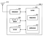
Next, the configuration of the small base station 200-1 according to the first embodiment will be described with reference to FIGS. FIG. 18 is a block diagram showing an example of the configuration of the small base station 200-1 according to the first embodiment. Referring to FIG. 18, the small base station 200-1 includes anantenna unit 210, a radio communication unit 220, a network communication unit 230, a storage unit 240, and a processing unit 250.
次に、図18~図22を参照して、第1の実施形態に係るスモール基地局200-1の構成を説明する。図18は、第1の実施形態に係るスモール基地局200-1の構成の一例を示すブロック図である。図18を参照すると、スモール基地局200-1は、アンテナ部210、無線通信部220、ネットワーク通信部230、記憶部240及び処理部250を備える。 <3.2. Configuration of small base station>
Next, the configuration of the small base station 200-1 according to the first embodiment will be described with reference to FIGS. FIG. 18 is a block diagram showing an example of the configuration of the small base station 200-1 according to the first embodiment. Referring to FIG. 18, the small base station 200-1 includes an
(アンテナ部210)
アンテナ部210は、無線通信部220により出力される信号を電波として空間に放射する。また、アンテナ部210は、空間の電波を信号に変換し、当該信号を無線通信部220へ出力する。 (Antenna unit 210)
Theantenna unit 210 radiates the signal output from the wireless communication unit 220 to the space as a radio wave. Further, the antenna unit 210 converts a radio wave in the space into a signal and outputs the signal to the wireless communication unit 220.
アンテナ部210は、無線通信部220により出力される信号を電波として空間に放射する。また、アンテナ部210は、空間の電波を信号に変換し、当該信号を無線通信部220へ出力する。 (Antenna unit 210)
The
(無線通信部220)
無線通信部220は、無線通信を行う。例えば、無線通信部220は、スモールセル20内に位置する端末装置へのダウンリンク信号を送信し、スモールセル20内に位置する端末装置からのアップリンク信号を受信する。 (Wireless communication unit 220)
Thewireless communication unit 220 performs wireless communication. For example, the radio communication unit 220 transmits a downlink signal to a terminal device located in the small cell 20 and receives an uplink signal from the terminal device located in the small cell 20.
無線通信部220は、無線通信を行う。例えば、無線通信部220は、スモールセル20内に位置する端末装置へのダウンリンク信号を送信し、スモールセル20内に位置する端末装置からのアップリンク信号を受信する。 (Wireless communication unit 220)
The
(ネットワーク通信部230)
ネットワーク通信部230は、他のノードと通信する。例えば、ネットワーク通信部230は、制御装置100-1と通信する。また、例えば、ネットワーク通信部230は、他のスモール基地局200-1と通信する。また、例えば、ネットワーク通信部230は、コアネットワーク40内に位置するコアネットワークノード、及び/又はマクロ基地局11と通信する。なお、ネットワーク通信部230は、インターネット50を介して他のノードと通信する。 (Network communication unit 230)
Thenetwork communication unit 230 communicates with other nodes. For example, the network communication unit 230 communicates with the control device 100-1. For example, the network communication unit 230 communicates with another small base station 200-1. For example, the network communication unit 230 communicates with the core network node and / or the macro base station 11 located in the core network 40. The network communication unit 230 communicates with other nodes via the Internet 50.
ネットワーク通信部230は、他のノードと通信する。例えば、ネットワーク通信部230は、制御装置100-1と通信する。また、例えば、ネットワーク通信部230は、他のスモール基地局200-1と通信する。また、例えば、ネットワーク通信部230は、コアネットワーク40内に位置するコアネットワークノード、及び/又はマクロ基地局11と通信する。なお、ネットワーク通信部230は、インターネット50を介して他のノードと通信する。 (Network communication unit 230)
The
(記憶部240)
記憶部240は、スモール基地局200-1の動作のためのプログラム及びデータを一時的にまたは恒久的に記憶する。 (Storage unit 240)
Thestorage unit 240 temporarily or permanently stores a program and data for the operation of the small base station 200-1.
記憶部240は、スモール基地局200-1の動作のためのプログラム及びデータを一時的にまたは恒久的に記憶する。 (Storage unit 240)
The
(処理部250)
処理部250は、スモール基地局200-1の様々な機能を提供する。処理部250は、情報取得部251及び通信制御部253を含む。 (Processing unit 250)
Theprocessing unit 250 provides various functions of the small base station 200-1. The processing unit 250 includes an information acquisition unit 251 and a communication control unit 253.
処理部250は、スモール基地局200-1の様々な機能を提供する。処理部250は、情報取得部251及び通信制御部253を含む。 (Processing unit 250)
The
(情報取得部251)
-グループMCCH構成情報の取得
情報取得部251は、特定の端末グループ用のMBSFNサブフレーム(即ち、グループMBSFNサブフレーム)に配置されるマルチキャストチャネルの構成を示すチャネル構成情報を取得する。上述したように、上記特定の端末グループは、例えばCSGである。 (Information acquisition unit 251)
-Acquisition of group MCCH configuration information Theinformation acquisition unit 251 acquires channel configuration information indicating a configuration of a multicast channel arranged in an MBSFN subframe for a specific terminal group (that is, a group MBSFN subframe). As described above, the specific terminal group is, for example, a CSG.
-グループMCCH構成情報の取得
情報取得部251は、特定の端末グループ用のMBSFNサブフレーム(即ち、グループMBSFNサブフレーム)に配置されるマルチキャストチャネルの構成を示すチャネル構成情報を取得する。上述したように、上記特定の端末グループは、例えばCSGである。 (Information acquisition unit 251)
-Acquisition of group MCCH configuration information The
とりわけ第1の実施形態では、上記マルチキャストチャネルは、MCCHである。即ち、情報取得部251は、グループMBSFNサブフレームに配置されるMCCHの構成を示すチャネル構成情報(以下、「グループMCCH構成情報」と呼ぶ)を取得する。
Especially in the first embodiment, the multicast channel is MCCH. That is, information acquisition section 251 acquires channel configuration information (hereinafter referred to as “group MCCH configuration information”) indicating the configuration of MCCH arranged in the group MBSFN subframe.
なお、上記マルチキャストチャネル(MCCH)は、グループMBSFNサブフレームに配置されるので、特定の端末グループ用のマルチキャストチャネル(MCCH)であると言える。
Note that since the multicast channel (MCCH) is arranged in the group MBSFN subframe, it can be said to be a multicast channel (MCCH) for a specific terminal group.
--具体的な内容
例えば、上記グループMCCH構成情報は、上記マルチキャストチャネル(即ち、MCCH)が配置されるサブフレームを示す情報を含む。より具体的には、例えば、上記グループMCCH構成情報は、MCCH反復期間、MCCHオフセット及びサブフレーム割当て情報を含む。 --Specific Content For example, the group MCCH configuration information includes information indicating a subframe in which the multicast channel (that is, MCCH) is arranged. More specifically, for example, the group MCCH configuration information includes an MCCH repetition period, an MCCH offset, and subframe allocation information.
例えば、上記グループMCCH構成情報は、上記マルチキャストチャネル(即ち、MCCH)が配置されるサブフレームを示す情報を含む。より具体的には、例えば、上記グループMCCH構成情報は、MCCH反復期間、MCCHオフセット及びサブフレーム割当て情報を含む。 --Specific Content For example, the group MCCH configuration information includes information indicating a subframe in which the multicast channel (that is, MCCH) is arranged. More specifically, for example, the group MCCH configuration information includes an MCCH repetition period, an MCCH offset, and subframe allocation information.
さらに、例えば、上記グループMCCH構成情報は、例えば、MCCH変更期間(MCCH Modification Period)及び/又はシグナリングMCS(Modulation and Coding Scheme)を含む。
Further, for example, the group MCCH configuration information includes, for example, an MCCH modification period (MCCH Modification Period) and / or a signaling MCS (Modulation and Coding Scheme).
なお、上記グループMCCH構成情報は、MBSFNエリアID、非MBSFN領域長(Non-MBSFN Region Length)をさらに含んでもよい。また、上記グループMCCH構成情報は、MCCHの情報の変更の通知に関する情報をさらに含んでもよい。
The group MCCH configuration information may further include an MBSFN area ID and a non-MBSFN region length. Further, the group MCCH configuration information may further include information related to notification of a change in MCCH information.
このように、上記MCCH構成情報は、一般的にはSIB13に含まれている情報のうちの一部又は全部を含む。
Thus, the MCCH configuration information generally includes part or all of the information included in the SIB 13.
-グループPMCH構成情報の取得
例えば、情報取得部251は、上記グループMBSFNサブフレームに配置されるPMCHの構成を示すグループPMCH構成情報をさらに取得する。上述したように、上記特定の端末グループは、例えばCSGである。 -Acquisition of group PMCH configuration information For example, theinformation acquisition unit 251 further acquires group PMCH configuration information indicating the configuration of the PMCH arranged in the group MBSFN subframe. As described above, the specific terminal group is, for example, a CSG.
例えば、情報取得部251は、上記グループMBSFNサブフレームに配置されるPMCHの構成を示すグループPMCH構成情報をさらに取得する。上述したように、上記特定の端末グループは、例えばCSGである。 -Acquisition of group PMCH configuration information For example, the
なお、上記PMCHは、グループMBSFNサブフレームに配置されるので、特定の端末グループ用のPMCHであると言える。
Note that, since the PMCH is arranged in the group MBSFN subframe, it can be said that it is a PMCH for a specific terminal group.
--具体的な内容
例えば、上記グループPMCH構成情報は、MBSFNエリアコンフィギュレーションメッセージである。 --Specific Content For example, the group PMCH configuration information is an MBSFN area configuration message.
例えば、上記グループPMCH構成情報は、MBSFNエリアコンフィギュレーションメッセージである。 --Specific Content For example, the group PMCH configuration information is an MBSFN area configuration message.
より具体的には、例えば、上記グループPMCH構成情報は、共通サブフレーム割当て(CSA)パターンリスト及びCSA期間を含む。一例として、上記CSAパターンリスト及び上記CSA期間は、通常のMBSFNサブフレーム及びグループMBSFNサブフレームを含むMBSFNサブフレームを示す。この場合に、例えば、上記グループPMCH構成情報は、上記CSAパターンリスト及び上記CSA期間により示されるMBSFNサブフレームに含まれる通常のMBSFNサブフレームとグループMBSFNサブフレームとを区別するための情報をさらに含む。別の例として、上記CSAパターンリスト及び上記CSA期間は、グループMBSFNサブフレームを示してもよい。
More specifically, for example, the group PMCH configuration information includes a common subframe allocation (CSA) pattern list and a CSA period. As an example, the CSA pattern list and the CSA period indicate an MBSFN subframe including a normal MBSFN subframe and a group MBSFN subframe. In this case, for example, the group PMCH configuration information further includes information for distinguishing a normal MBSFN subframe and a group MBSFN subframe included in the MBSFN subframe indicated by the CSA pattern list and the CSA period. . As another example, the CSA pattern list and the CSA period may indicate a group MBSFN subframe.
また、例えば、上記グループPMCH構成情報は、PMCH情報リストを含む。当該PMCH情報リストは、例えば、上記特定の端末グループ用の各PMCHが配置されるグループMBSFNサブフレームを示す。即ち、当該PMCH情報リストは、例えば、各PMCHのサブフレーム割当て終了(Subframe Allocation End)を含む。さらに、上記PMCH情報リストは、例えば、各PMCHのMCHスケジューリング期間(MSP)も含む。また、上記PMCH情報リストは、例えば、上記特定の端末グループ用の各PMCHにマッピングされる1つ以上のMTCH(即ち、上記特定の端末グループ用の1つ以上のMTCH)を示す。即ち、上記PMCH情報リストは、例えば、MBMSセッション情報リストを含み、当該MBMSセッション情報リストは、TMGI(Temporary Mobile Group Identify)、セッションID及び論理チャネルIDを含む。
For example, the group PMCH configuration information includes a PMCH information list. The PMCH information list indicates, for example, a group MBSFN subframe in which each PMCH for the specific terminal group is arranged. That is, the PMCH information list includes, for example, subframe allocation end of each PMCH. Further, the PMCH information list includes, for example, an MCH scheduling period (MSP) of each PMCH. The PMCH information list indicates, for example, one or more MTCHs (that is, one or more MTCHs for the specific terminal group) mapped to each PMCH for the specific terminal group. That is, the PMCH information list includes, for example, an MBMS session information list, and the MBMS session information list includes a TMGI (Temporary Mobile Group Identify), a session ID, and a logical channel ID.
-通常MCCH構成情報の取得
例えば、情報取得部251は、通常のMBSFNサブフレームに配置されるMCCHの構成を示す通常MCCH構成情報をさらに取得する。 -Acquisition of normal MCCH configuration information For example, theinformation acquisition unit 251 further acquires normal MCCH configuration information indicating the configuration of the MCCH arranged in a normal MBSFN subframe.
例えば、情報取得部251は、通常のMBSFNサブフレームに配置されるMCCHの構成を示す通常MCCH構成情報をさらに取得する。 -Acquisition of normal MCCH configuration information For example, the
--具体的な内容
上記通常MCCH構成情報は、例えば、上記グループMCCH構成情報に含まれる情報項目(MCCH反復期間、MCCHオフセット及びサブフレーム割当て情報など)と同一の情報項目を含む。 --Specific Content The normal MCCH configuration information includes, for example, the same information items as the information items (MCCH repetition period, MCCH offset, subframe allocation information, etc.) included in the group MCCH configuration information.
上記通常MCCH構成情報は、例えば、上記グループMCCH構成情報に含まれる情報項目(MCCH反復期間、MCCHオフセット及びサブフレーム割当て情報など)と同一の情報項目を含む。 --Specific Content The normal MCCH configuration information includes, for example, the same information items as the information items (MCCH repetition period, MCCH offset, subframe allocation information, etc.) included in the group MCCH configuration information.
より具体的には、上記通常MCCH構成情報は、システム情報ブロック(例えば、SIB)に含まれる情報である。この場合に、情報取得部251は、上記通常MCCH構成情報を含む上記システム情報ブロックを取得する。
More specifically, the normal MCCH configuration information is information included in a system information block (for example, SIB). In this case, the information acquisition unit 251 acquires the system information block including the normal MCCH configuration information.
-通常PMCH構成情報の取得
例えば、情報取得部251は、通常のMBSFNサブフレームに配置されるPMCHの構成を示す通常PMCH構成情報をさらに取得する。 -Acquisition of normal PMCH configuration information For example, theinformation acquisition unit 251 further acquires normal PMCH configuration information indicating the configuration of the PMCH arranged in a normal MBSFN subframe.
例えば、情報取得部251は、通常のMBSFNサブフレームに配置されるPMCHの構成を示す通常PMCH構成情報をさらに取得する。 -Acquisition of normal PMCH configuration information For example, the
--具体的な内容
例えば、上記通常PMCH構成情報は、MBSFNエリアコンフィギュレーションメッセージである。 --Specific Content For example, the normal PMCH configuration information is an MBSFN area configuration message.
例えば、上記通常PMCH構成情報は、MBSFNエリアコンフィギュレーションメッセージである。 --Specific Content For example, the normal PMCH configuration information is an MBSFN area configuration message.
より具体的には、例えば、上記通常PMCH構成情報は、共通サブフレーム割当て(CSA)パターンリスト及びCSA期間を含む。一例として、上記CSAパターンリスト及び上記CSA期間は、通常のMBSFNサブフレーム及びグループMBSFNサブフレームを含むMBSFNサブフレームを示す。この場合に、例えば、上記通常PMCH構成情報は、上記CSAパターンリスト及び上記CSA期間により示されるMBSFNサブフレームに含まれる通常のMBSFNサブフレームとグループMBSFNサブフレームとを区別するための情報をさらに含む。別の例として、上記CSAパターンリスト及び上記CSA期間は、通常のMBSFNサブフレームを示してもよい。
More specifically, for example, the normal PMCH configuration information includes a common subframe allocation (CSA) pattern list and a CSA period. As an example, the CSA pattern list and the CSA period indicate an MBSFN subframe including a normal MBSFN subframe and a group MBSFN subframe. In this case, for example, the normal PMCH configuration information further includes information for distinguishing the normal MBSFN subframe and the group MBSFN subframe included in the MBSFN subframe indicated by the CSA pattern list and the CSA period. . As another example, the CSA pattern list and the CSA period may indicate a normal MBSFN subframe.
また、例えば、上記通常PMCH構成情報は、PMCH情報リストを含む。当該PMCH情報リストは、例えば、各PMCHが配置される通常のMBSFNサブフレーム、及び各PMCHにマッピングされる1つ以上のMTCHを示す。
For example, the normal PMCH configuration information includes a PMCH information list. The PMCH information list indicates, for example, a normal MBSFN subframe in which each PMCH is arranged, and one or more MTCHs mapped to each PMCH.
(通信制御部253)
-グループMCCH構成情報の通知
通信制御部253は、上記グループMBSFNサブフレームに配置されるマルチキャストチャネルの構成を示す上記チャネル構成情報を、上記特定の端末グループに通知する。とりわけ第1の実施形態では、上記チャネル構成情報は、上記グループMCCH構成情報であり、通信制御部253は、上記グループMCCH構成情報を上記特定の端末グループに通知する。 (Communication control unit 253)
-Notification of group MCCH configuration information Thecommunication control unit 253 notifies the specific terminal group of the channel configuration information indicating the configuration of the multicast channel arranged in the group MBSFN subframe. Particularly, in the first embodiment, the channel configuration information is the group MCCH configuration information, and the communication control unit 253 notifies the specific terminal group of the group MCCH configuration information.
-グループMCCH構成情報の通知
通信制御部253は、上記グループMBSFNサブフレームに配置されるマルチキャストチャネルの構成を示す上記チャネル構成情報を、上記特定の端末グループに通知する。とりわけ第1の実施形態では、上記チャネル構成情報は、上記グループMCCH構成情報であり、通信制御部253は、上記グループMCCH構成情報を上記特定の端末グループに通知する。 (Communication control unit 253)
-Notification of group MCCH configuration information The
--特定の端末グループ用の識別情報の使用による通知
例えば、通信制御部253は、上記特定の端末グループ用の識別情報を使用して、上記グループMCCH構成情報を上記特定の端末グループに通知する。 -Notification by use of identification information for specific terminal group For example, thecommunication control unit 253 notifies the specific terminal group of the group MCCH configuration information using the identification information for the specific terminal group. .
例えば、通信制御部253は、上記特定の端末グループ用の識別情報を使用して、上記グループMCCH構成情報を上記特定の端末グループに通知する。 -Notification by use of identification information for specific terminal group For example, the
より具体的には、例えば、上記特定の端末グループ用の上記識別情報は、上記特定の端末グループ用のRNTI(Radio Network Temporary Identifier)(以下、「グループRNTI」と呼ぶ)である。これにより、例えば、上記特定の端末グループに属する端末装置のみに、上記グループMCCH構成情報を通知することが可能になる。
More specifically, for example, the identification information for the specific terminal group is an RNTI (Radio Network Temporary Identifier) for the specific terminal group (hereinafter referred to as “group RNTI”). Thereby, for example, the group MCCH configuration information can be notified only to the terminal devices belonging to the specific terminal group.
また、例えば、通信制御部253は、上記特定の端末グループに属する端末装置に上記識別情報を通知する。これにより、例えば、上記特定の端末グループに属する端末装置が、上記グループMCCH構成情報を実際に取得することが可能になる。
For example, the communication control unit 253 notifies the identification information to the terminal devices belonging to the specific terminal group. Thereby, for example, terminal devices belonging to the specific terminal group can actually acquire the group MCCH configuration information.
--具体的な通知の手法
例えば、通信制御部253は、上記グループRNTIを使用して、PDCCH上で送信されるDCIを通じて、上記グループMCCH構成情報を上記特定の端末グループに通知する。これにより、例えば、グループMCCH構成情報を必要に応じて迅速に上記特定の端末グループに通知することが可能になる。なお、上記PDCCHは、通常のPDCCHであってもよく、又はePDCCH(enhanced Physical Downlink Control Channel)であってもよい。 --Specific Notification Method For example, thecommunication control unit 253 uses the group RNTI to notify the specific terminal group of the group MCCH configuration information through DCI transmitted on the PDCCH. Thereby, for example, the group MCCH configuration information can be promptly notified to the specific terminal group as necessary. The PDCCH may be a normal PDCCH or an ePDCCH (enhanced Physical Downlink Control Channel).
例えば、通信制御部253は、上記グループRNTIを使用して、PDCCH上で送信されるDCIを通じて、上記グループMCCH構成情報を上記特定の端末グループに通知する。これにより、例えば、グループMCCH構成情報を必要に応じて迅速に上記特定の端末グループに通知することが可能になる。なお、上記PDCCHは、通常のPDCCHであってもよく、又はePDCCH(enhanced Physical Downlink Control Channel)であってもよい。 --Specific Notification Method For example, the
---第1の例
第1の例として、通信制御部253は、上記グループRNTIを使用して、PDCCH上で送信されるDCIの中で上記グループMCCH構成情報を上記特定の端末グループに通知する。 --- 1st example As a 1st example, thecommunication control part 253 notifies the said group MCCH structure information to the said specific terminal group in DCI transmitted on PDCCH using the said group RNTI. To do.
第1の例として、通信制御部253は、上記グループRNTIを使用して、PDCCH上で送信されるDCIの中で上記グループMCCH構成情報を上記特定の端末グループに通知する。 --- 1st example As a 1st example, the
より具体的には、例えば、通信制御部253は、グループRNTIによりスクランブリングされたCRC(Cyclic Redundancy Check)ビットとグループMCCH構成情報とを含むDCI(即ち、特定の端末グループ用のDCI)を生成する。そして、通信制御部253は、当該DCIをPDCCHの無線リソースにマッピングする。その結果、当該DCIがPDCCH上で送信される。これにより、上記特定の端末グループに属する端末装置は、グループRNTIを使用してグループMCCH構成情報を取得することができる。また、とりわけこの手法によれば、例えば、端末装置は、DCIのみからグループMCCH構成情報を取得することができるので、端末装置にとっての負担を小さくすることが可能になる。以下、図19及び図20を参照して具体例を説明する。
More specifically, for example, the communication control unit 253 generates DCI (that is, DCI for a specific terminal group) including CRC (Cyclic Redundancy Check) bits scrambled by the group RNTI and group MCCH configuration information. To do. And the communication control part 253 maps the said DCI to the radio | wireless resource of PDCCH. As a result, the DCI is transmitted on the PDCCH. Thereby, the terminal device which belongs to the said specific terminal group can acquire group MCCH structure information using group RNTI. In particular, according to this method, for example, the terminal device can acquire the group MCCH configuration information only from the DCI, so that the burden on the terminal device can be reduced. Hereinafter, specific examples will be described with reference to FIGS. 19 and 20.
図19は、DCIの中でのグループMCCH構成情報の通知の一例を説明するための説明図である。図19を参照すると、非MBSFNサブフレームの無線リソースが示されている。例えば、PDCCHなどが配置されるPDCCH領域(例えば、3OFDMシンボル又は2OFDMシンボルの領域)内のPDCCH上で、上記CRCビットと上記グループMCCH構成情報とを含むDCI(特定の端末グループ用のDCI)が送信される。
FIG. 19 is an explanatory diagram for explaining an example of notification of group MCCH configuration information in DCI. Referring to FIG. 19, radio resources of non-MBSFN subframes are shown. For example, a DCI (DCI for a specific terminal group) including the CRC bits and the group MCCH configuration information on a PDCCH in a PDCCH region (for example, a region of 3 OFDM symbols or 2 OFDM symbols) where a PDCCH or the like is arranged Sent.
図20は、DCIの中でのグループMCCH構成情報の通知の別の例を説明するための説明図である。図20を参照すると、MBSFNサブフレームの無線リソースが示されている。例えば、非MBSFN領域内のPDCCH上で、上記CRCビットと上記グループMCCH構成情報とを含むDCI(特定の端末グループ用のDCI)が送信される。
FIG. 20 is an explanatory diagram for explaining another example of notification of group MCCH configuration information in DCI. Referring to FIG. 20, the radio resources of the MBSFN subframe are shown. For example, DCI (DCI for a specific terminal group) including the CRC bits and the group MCCH configuration information is transmitted on the PDCCH in the non-MBSFN region.
---第2の例
第2の例として、通信制御部253は、上記グループRNTIを使用して、PDCCH上で送信されるDCIの中で、上記グループMCCH構成情報が送信される無線リソースを示すリソース割当て情報を上記特定の端末グループに通知することにより、上記グループMCCH構成情報を上記特定の端末グループに通知する。 --- Second Example As a second example, thecommunication control unit 253 uses the group RNTI to change the radio resource for transmitting the group MCCH configuration information in the DCI transmitted on the PDCCH. By notifying the resource allocation information shown to the specific terminal group, the group MCCH configuration information is notified to the specific terminal group.
第2の例として、通信制御部253は、上記グループRNTIを使用して、PDCCH上で送信されるDCIの中で、上記グループMCCH構成情報が送信される無線リソースを示すリソース割当て情報を上記特定の端末グループに通知することにより、上記グループMCCH構成情報を上記特定の端末グループに通知する。 --- Second Example As a second example, the
より具体的には、例えば、通信制御部253は、グループRNTIによりスクランブリングされたCRCビットと、グループMCCH構成情報が送信される無線リソースを示すリソース割当て情報とを含む、DCI(即ち、特定の端末グループ用のDCI)を生成する。そして、通信制御部253は、当該DCIを、非MBSFNサブフレーム内のPDCCHの無線リソースにマッピングする。これにより、上記特定の端末グループに属する端末装置は、グループRNTIを使用して、グループMCCH構成情報が送信される無線リソース(即ち、PDSCHの無線リソース)を特定することができる。よって、当該端末装置は、上記無線リソースで送信されるグループMCCH構成情報を取得することができる。また、とりわけこの手法によれば、例えば、DCIのビット数が大きくなることを避けることが可能になる。また、この手法によれば、例えば、大きいサイズのグループMCCH構成情報を送信することが可能になる。なお、通信制御部253は、例えば、グループMCCH構成情報を、上記リソース割当て情報により示される上記無線リソース(PDSCHの無線リソース)にマッピングする。これにより、上記グループMCCH構成情報が上記無線リソースで実際に送信される。以下、図21を参照して具体例を説明する。
More specifically, for example, the communication control unit 253 includes DCI (that is, specific information) including CRC bits scrambled by the group RNTI and resource allocation information indicating a radio resource to which the group MCCH configuration information is transmitted. DCI for the terminal group is generated. Then, the communication control unit 253 maps the DCI to the PDCCH radio resource in the non-MBSFN subframe. Thereby, the terminal apparatus which belongs to the said specific terminal group can specify the radio | wireless resource (namely, radio | wireless resource of PDSCH) by which group MCCH structure information is transmitted using group RNTI. Therefore, the terminal apparatus can acquire group MCCH configuration information transmitted using the radio resource. In particular, according to this method, for example, it is possible to avoid an increase in the number of bits of DCI. Further, according to this method, for example, it is possible to transmit large-sized group MCCH configuration information. Note that the communication control unit 253, for example, maps the group MCCH configuration information to the radio resource (PDSCH radio resource) indicated by the resource allocation information. Thereby, the group MCCH configuration information is actually transmitted using the radio resource. Hereinafter, a specific example will be described with reference to FIG.
図21は、割り当てられた無線リソースでのグループMCCH構成情報の通知の例を説明するための説明図である。図21を参照すると、非MBSFNサブフレームの無線リソースが示されている。例えば、PDCCHなどが配置されるPDCCH領域(例えば、3OFDMシンボル又は2OFDMシンボルの領域)内のPDCCH上で、上記CRCビットと上記リソース割当て情報とを含むDCI(特定の端末グループ用のDCI)が送信される。また、当該リソース割当て情報により示される無線リソース(PDSCHの無線リソース)で、グループMCCH構成情報が送信される。
FIG. 21 is an explanatory diagram for explaining an example of notification of group MCCH configuration information with assigned radio resources. Referring to FIG. 21, radio resources of non-MBSFN subframes are shown. For example, DCI (DCI for a specific terminal group) including the CRC bits and the resource allocation information is transmitted on a PDCCH in a PDCCH region (for example, a region of 3 OFDM symbols or 2 OFDM symbols) in which PDCCH or the like is arranged. Is done. Also, group MCCH configuration information is transmitted using the radio resource (PDSCH radio resource) indicated by the resource allocation information.
例えば以上のような通知の手法により、上記特定の端末グループは、上記グループMCCH構成情報を通知される。なお、特定の端末グループに暗号鍵を提供し、当該特定の端末グループにマルチキャストされるデータを上記暗号鍵により暗号化することによっても、特定の端末グループへのマルチキャストは実現され得る。しかし、このような手法によれば、上記特定の端末グループに属さない端末装置も、暗号化されたデータの受信を試みてしまうので、当該端末装置の電力が浪費され、また当該端末装置にとってのサービス品質が低下し得る。そのため、上述したような通知の手法によれば、特定の端末グループに属さない端末装置の電力の浪費、及び/又は当該端末装置にとってのサービス品質の低下などが、回避され得る。
For example, by the notification method as described above, the specific terminal group is notified of the group MCCH configuration information. Multicast to a specific terminal group can also be realized by providing an encryption key to a specific terminal group and encrypting data multicast to the specific terminal group with the encryption key. However, according to such a method, since the terminal device that does not belong to the specific terminal group also tries to receive the encrypted data, the power of the terminal device is wasted, and for the terminal device Service quality can be degraded. Therefore, according to the notification method as described above, waste of power of a terminal device that does not belong to a specific terminal group and / or deterioration of service quality for the terminal device can be avoided.
--通知のタイミング
第1に、例えば、通信制御部253は、MCCHの情報が変更されるときに、上記グループMCCH構成情報を上記特定の端末グループに通知する。これにより、例えば、端末装置は、同一のグループMCCH構成情報及びMCCHの同一の情報を繰り返し取得しないので、端末装置の負担を軽減することができる。 -Timing of notification First, for example, thecommunication control unit 253 notifies the specific terminal group of the group MCCH configuration information when MCCH information is changed. Thereby, for example, since the terminal device does not repeatedly acquire the same group MCCH configuration information and the same information of the MCCH, the burden on the terminal device can be reduced.
第1に、例えば、通信制御部253は、MCCHの情報が変更されるときに、上記グループMCCH構成情報を上記特定の端末グループに通知する。これにより、例えば、端末装置は、同一のグループMCCH構成情報及びMCCHの同一の情報を繰り返し取得しないので、端末装置の負担を軽減することができる。 -Timing of notification First, for example, the
第2に、例えば、通信制御部253は、上記特定の端末グループに属する端末装置がMBSFNエリア30において接続されるときに、上記グループMCCH構成情報を当該端末装置に通知する。より具体的には、例えば、上記MBSFNエリア外のセルから上記MBSFNエリア内のセルへの上記端末装置のハンドオーバが行われるときに、通信制御部253は、上記グループMCCH構成情報を上記端末装置に通知する。また、例えば、上記MBSFNエリア内のセル内で、上記端末装置のモードがRRCアイドルモードからRRC接続モードへ遷移するときに、通信制御部253は、上記グループMCCH構成情報を上記端末装置に通知する。これにより、例えば、上記グループMCCH構成情報が上記特定の端末グループに繰り返し通知されない場合でも、上記特定の端末グループに属する端末装置は、MBSFNエリア30において接続されるときに、上記グループMCCH構成情報を迅速に取得することが可能になる。
Second, for example, when the terminal device belonging to the specific terminal group is connected in the MBSFN area 30, the communication control unit 253 notifies the terminal device of the group MCCH configuration information. More specifically, for example, when the terminal apparatus is handed over from a cell outside the MBSFN area to a cell within the MBSFN area, the communication control unit 253 transmits the group MCCH configuration information to the terminal apparatus. Notice. Also, for example, when the mode of the terminal device transitions from the RRC idle mode to the RRC connection mode in the cell in the MBSFN area, the communication control unit 253 notifies the group MCCH configuration information to the terminal device. . Thereby, for example, even when the group MCCH configuration information is not repeatedly notified to the specific terminal group, when the terminal devices belonging to the specific terminal group are connected in the MBSFN area 30, the group MCCH configuration information is displayed. It becomes possible to obtain quickly.
なお、通信制御部253は、上記端末装置が上記MBSFNエリアにおいて接続されるときには、上記端末装置用の識別情報を使用して、上記グループMCCH構成情報を当該端末装置に通知してもよい。当該識別情報は、例えば、C-RNTI(Cell RNTI)であってもよい。これにより、例えば、MBSFNエリアにおいて接続される端末装置のみへの通知が行われるので、上記特定の端末グループに属する他の端末装置の負担を軽減することが可能になる。
Note that when the terminal device is connected in the MBSFN area, the communication control unit 253 may notify the terminal device of the group MCCH configuration information using the identification information for the terminal device. The identification information may be, for example, C-RNTI (Cell RNTI). As a result, for example, only the terminal devices connected in the MBSFN area are notified, so it is possible to reduce the burden on other terminal devices belonging to the specific terminal group.
以上のように、通信制御部253は、上記グループMCCH構成情報を上記特定の端末グループに通知する。これにより、例えば、上記特定の端末グループに属する端末装置が上記特定の端末グループ用のMCCHの情報を取得することが可能になる。そのため、当該端末装置は、上記特定の端末グループ用のPMCHと、当該PMCHにマッピングされるMTCH(即ち、上記特定の端末グループ用のMTCH)とを特定し得る。即ち、上記特定の端末グループへのマルチキャストが行われ得る。
As described above, the communication control unit 253 notifies the specific terminal group of the group MCCH configuration information. As a result, for example, terminal devices belonging to the specific terminal group can acquire the MCCH information for the specific terminal group. Therefore, the terminal apparatus can specify the PMCH for the specific terminal group and the MTCH mapped to the PMCH (that is, the MTCH for the specific terminal group). That is, multicast to the specific terminal group can be performed.
なお、通信制御部253は、例えば、システム情報ブロック(例えば、SIB13)の中で上記グループMCCH構成情報を報知しない。これにより、例えば、上記特定の端末グループに属さない端末装置は上記グループMCCH構成情報を取得しない。そのため、上記特定の端末グループのみへのマルチキャストが行われ得る。
Note that the communication control unit 253 does not broadcast the group MCCH configuration information in a system information block (for example, SIB13), for example. Thereby, for example, a terminal device that does not belong to the specific terminal group does not acquire the group MCCH configuration information. Therefore, multicasting to only the specific terminal group can be performed.
-グループPMCH構成情報の通知
例えば、通信制御部253は、上記グループMBSFNサブフレームに配置されるPMCHの構成を示す上記グループPMCH構成情報を、上記特定の端末グループに通知する。 -Notification of group PMCH configuration information For example, thecommunication control unit 253 notifies the specific terminal group of the group PMCH configuration information indicating the configuration of the PMCH arranged in the group MBSFN subframe.
例えば、通信制御部253は、上記グループMBSFNサブフレームに配置されるPMCHの構成を示す上記グループPMCH構成情報を、上記特定の端末グループに通知する。 -Notification of group PMCH configuration information For example, the
例えば、通信制御部253は、上記グループMBSFNサブフレームに配置されるMCCH(即ち、上記特定の端末グループ用のMCCH)上で、上記グループPMCH構成情報を上記特定の端末グループに通知する。
For example, the communication control unit 253 notifies the specific terminal group of the group PMCH configuration information on the MCCH (that is, the MCCH for the specific terminal group) arranged in the group MBSFN subframe.
-通常MCCH構成情報の通知
例えば、通信制御部253は、上記通常のMBSFNサブフレームに配置されるMCCHの構成を示す上記通常MCCH構成情報を、端末装置に通知する。例えば、通信制御部253は、上記通常MCCH構成情報を含むシステム情報ブロック(例えば、SIB13)を報知する。 -Notification of normal MCCH configuration information For example, thecommunication control unit 253 notifies the terminal device of the normal MCCH configuration information indicating the configuration of the MCCH arranged in the normal MBSFN subframe. For example, the communication control unit 253 broadcasts a system information block (for example, SIB13) including the normal MCCH configuration information.
例えば、通信制御部253は、上記通常のMBSFNサブフレームに配置されるMCCHの構成を示す上記通常MCCH構成情報を、端末装置に通知する。例えば、通信制御部253は、上記通常MCCH構成情報を含むシステム情報ブロック(例えば、SIB13)を報知する。 -Notification of normal MCCH configuration information For example, the
-通常PMCH構成情報の通知
例えば、通信制御部253は、上記通常のMBSFNサブフレームに配置されるPMCHの構成を示す上記通常PMCH構成情報を、端末装置に通知する。例えば、通信制御部253は、上記通常のMBSFNサブフレームに配置されるMCCH上で、上記通常PMCH構成情報を通知する。 -Notification of normal PMCH configuration information For example, thecommunication control unit 253 notifies the terminal device of the normal PMCH configuration information indicating the configuration of the PMCH arranged in the normal MBSFN subframe. For example, the communication control unit 253 notifies the normal PMCH configuration information on the MCCH arranged in the normal MBSFN subframe.
例えば、通信制御部253は、上記通常のMBSFNサブフレームに配置されるPMCHの構成を示す上記通常PMCH構成情報を、端末装置に通知する。例えば、通信制御部253は、上記通常のMBSFNサブフレームに配置されるMCCH上で、上記通常PMCH構成情報を通知する。 -Notification of normal PMCH configuration information For example, the
-MBSFNサブフレームの通知
例えば、通信制御部253は、MBSFNサブフレームを端末装置に通知する。 -Notification of MBSFN subframe For example, thecommunication control unit 253 notifies the terminal device of the MBSFN subframe.
例えば、通信制御部253は、MBSFNサブフレームを端末装置に通知する。 -Notification of MBSFN subframe For example, the
例えば、通信制御部253は、通常のMBSFNサブフレーム及びグループMBSFNサブフレームを含むMBSFNサブフレームのための無線フレーム割当て期間、無線フレーム割当てオフセット及びサブフレーム割当てを、端末装置に通知する。より具体的には、例えば、通信制御部253は、これらの情報を含むSIB2を報知する。
For example, the communication control unit 253 notifies the terminal device of a radio frame allocation period, a radio frame allocation offset, and a subframe allocation for MBSFN subframes including normal MBSFN subframes and group MBSFN subframes. More specifically, for example, the communication control unit 253 notifies the SIB2 including these pieces of information.
これにより、例えば、端末装置は、上記特定の端末グループに属するか否かによらず、全てのMBSFNのサブフレームを知ることができる。そのため、端末装置は、CRSの測定の対象とすべきサブフレームを知り得る。よって、CRSの測定が適切に行われ得る。
Thereby, for example, the terminal device can know all MBSFN subframes regardless of whether or not they belong to the specific terminal group. Therefore, the terminal device can know the subframe to be measured by CRS. Therefore, measurement of CRS can be appropriately performed.
(その他:MBSFN領域)
スモール基地局200-1は、MBSNFエリア30のMBMSサブフレームのフォーマットとして、いくつかの種類のフォーマットのうちのいずれかのフォーマットを使用し得る。 (Other: MBSFN area)
The small base station 200-1 may use any one of several types of formats as the MBMS subframe format of theMBSNF area 30.
スモール基地局200-1は、MBSNFエリア30のMBMSサブフレームのフォーマットとして、いくつかの種類のフォーマットのうちのいずれかのフォーマットを使用し得る。 (Other: MBSFN area)
The small base station 200-1 may use any one of several types of formats as the MBMS subframe format of the
第1の例として、MBSNFエリア30のMBMSサブフレームは、図4に示されるように、時間方向において12個のOFDMシンボルを含み、非MBMS領域は、当該12個のOFDMシンボルのうちの最初の2つのOFDMシンボルにわたる領域であってもよい。
As a first example, the MBMS subframe of the MBSNF area 30 includes 12 OFDM symbols in the time direction as shown in FIG. 4, and the non-MBMS region is the first of the 12 OFDM symbols. It may be a region extending over two OFDM symbols.
第2の例として、MBSNFエリア30のMBMSサブフレームは、時間方向において14個のOFDMシンボルを含んでもよい。MBSNFエリア30がスモールセルにより構成されることを考慮すると、サイクリックプレフィクス(CP)は短くてもよい場合もあるためである。そして、非MBMS領域は、上記14個のOFDMシンボルのうちの最初の3つのOFDMシンボルにわたる領域であってもよい。以下、図22を参照して、当該MBSFNサブフレームを説明する。
As a second example, the MBMS subframe of the MBSNF area 30 may include 14 OFDM symbols in the time direction. This is because the cyclic prefix (CP) may be short considering that the MBSNF area 30 is composed of small cells. The non-MBMS region may be a region extending over the first three OFDM symbols among the 14 OFDM symbols. Hereinafter, the MBSFN subframe will be described with reference to FIG.
図22は、MBMSサブフレームの例を説明するための説明図である。図22を参照すると、MBSFNサブフレーム内で時間方向に並ぶ2つのリソースブロック(RB)が示されている。この例では、MBSFNサブフレームは、時間方向において14個のOFDMシンボルを含む。また、MBSFNサブフレームは、14のOFDMシンボルのうちの最初の3つのOFDMシンボルにわたる非MBSFN領域と、その後に続くMBSFN領域とを含む。非MBSFN領域では、CRSが送信され得る。一方、MBSFN領域では、MBSFNエリアに属するセル間で共通のMBSFN-RSが送信される。また、MBSFN領域では、MCCHにマッピングされる制御情報又はMTCHにマッピングされるデータが送信される。
FIG. 22 is an explanatory diagram for explaining an example of an MBMS subframe. Referring to FIG. 22, two resource blocks (RB) arranged in the time direction in the MBSFN subframe are shown. In this example, the MBSFN subframe includes 14 OFDM symbols in the time direction. In addition, the MBSFN subframe includes a non-MBSFN region that extends over the first three OFDM symbols of the 14 OFDM symbols, and a subsequent MBSFN region. In the non-MBSFN region, CRS may be transmitted. On the other hand, in the MBSFN area, a common MBSFN-RS is transmitted between cells belonging to the MBSFN area. In the MBSFN region, control information mapped to MCCH or data mapped to MTCH is transmitted.
なお、当然ながら、MBSNFエリア30のMBMSサブフレームのフォーマットとして、上述した第1の例及び第2の例に示されたMBSFNサブフレームのフォーマット以外のフォーマットが使用されてもよい。
Of course, formats other than the MBSFN subframe formats shown in the first and second examples described above may be used as the MBMS subframe format of the MBSNF area 30.
<3.3.端末装置の構成>
次に、図23を参照して、第1の実施形態に係る端末装置300-1の構成を説明する。図23は、第1の実施形態に係る端末装置300-1の構成の一例を示すブロック図である。図23を参照すると、端末装置300-1は、アンテナ部310、無線通信部320、記憶部330及び処理部340を備える。 <3.3. Configuration of terminal device>
Next, the configuration of the terminal device 300-1 according to the first embodiment will be described with reference to FIG. FIG. 23 is a block diagram illustrating an example of the configuration of the terminal device 300-1 according to the first embodiment. Referring to FIG. 23, the terminal device 300-1 includes anantenna unit 310, a wireless communication unit 320, a storage unit 330, and a processing unit 340.
次に、図23を参照して、第1の実施形態に係る端末装置300-1の構成を説明する。図23は、第1の実施形態に係る端末装置300-1の構成の一例を示すブロック図である。図23を参照すると、端末装置300-1は、アンテナ部310、無線通信部320、記憶部330及び処理部340を備える。 <3.3. Configuration of terminal device>
Next, the configuration of the terminal device 300-1 according to the first embodiment will be described with reference to FIG. FIG. 23 is a block diagram illustrating an example of the configuration of the terminal device 300-1 according to the first embodiment. Referring to FIG. 23, the terminal device 300-1 includes an
(アンテナ部310)
アンテナ部310は、無線通信部320により出力される信号を電波として空間に放射する。また、アンテナ部310は、空間の電波を信号に変換し、当該信号を無線通信部320へ出力する。 (Antenna part 310)
Theantenna unit 310 radiates a signal output from the wireless communication unit 320 as a radio wave to space. Further, the antenna unit 310 converts radio waves in space into a signal and outputs the signal to the wireless communication unit 320.
アンテナ部310は、無線通信部320により出力される信号を電波として空間に放射する。また、アンテナ部310は、空間の電波を信号に変換し、当該信号を無線通信部320へ出力する。 (Antenna part 310)
The
(無線通信部320)
無線通信部320は、無線通信を行う。例えば、無線通信部320は、端末装置300-1がマクロセル10内に位置する場合に、マクロ基地局11からのダウンリンク信号を受信し、マクロ基地局11へのアップリンク信号を送信する。また、例えば、無線通信部320は、端末装置300-1がスモールセル20内に位置する場合に、スモール基地局200-1からのダウンリンク信号を受信し、スモール基地局200-1へのアップリンク信号を送信する。 (Wireless communication unit 320)
Thewireless communication unit 320 performs wireless communication. For example, when the terminal device 300-1 is located in the macro cell 10, the radio communication unit 320 receives a downlink signal from the macro base station 11 and transmits an uplink signal to the macro base station 11. Further, for example, when the terminal device 300-1 is located in the small cell 20, the radio communication unit 320 receives a downlink signal from the small base station 200-1 and uploads to the small base station 200-1. Send a link signal.
無線通信部320は、無線通信を行う。例えば、無線通信部320は、端末装置300-1がマクロセル10内に位置する場合に、マクロ基地局11からのダウンリンク信号を受信し、マクロ基地局11へのアップリンク信号を送信する。また、例えば、無線通信部320は、端末装置300-1がスモールセル20内に位置する場合に、スモール基地局200-1からのダウンリンク信号を受信し、スモール基地局200-1へのアップリンク信号を送信する。 (Wireless communication unit 320)
The
(記憶部330)
記憶部33は、端末装置300-1の動作のためのプログラム及びデータを一時的にまたは恒久的に記憶する。 (Storage unit 330)
The storage unit 33 temporarily or permanently stores a program and data for the operation of the terminal device 300-1.
記憶部33は、端末装置300-1の動作のためのプログラム及びデータを一時的にまたは恒久的に記憶する。 (Storage unit 330)
The storage unit 33 temporarily or permanently stores a program and data for the operation of the terminal device 300-1.
(処理部340)
処理部340は、端末装置300-1の様々な機能を提供する。処理部340は、情報取得部341及び通信制御部343を含む。 (Processing unit 340)
Theprocessing unit 340 provides various functions of the terminal device 300-1. The processing unit 340 includes an information acquisition unit 341 and a communication control unit 343.
処理部340は、端末装置300-1の様々な機能を提供する。処理部340は、情報取得部341及び通信制御部343を含む。 (Processing unit 340)
The
(情報取得部341)
-特定の端末グループ用の識別情報の取得
情報取得部341は、特定の端末グループ用の識別情報を取得する。例えば、当該特定の端末グループ用の当該識別情報は、上記特定の端末グループ用のRNTI(即ち、グループRNTI)である。なお、上述したように、端末装置300-1は、当該特定の端末グループに属する。 (Information acquisition unit 341)
-Acquisition of Identification Information for Specific Terminal Group Theinformation acquisition unit 341 acquires identification information for a specific terminal group. For example, the identification information for the specific terminal group is the RNTI for the specific terminal group (that is, the group RNTI). As described above, the terminal device 300-1 belongs to the specific terminal group.
-特定の端末グループ用の識別情報の取得
情報取得部341は、特定の端末グループ用の識別情報を取得する。例えば、当該特定の端末グループ用の当該識別情報は、上記特定の端末グループ用のRNTI(即ち、グループRNTI)である。なお、上述したように、端末装置300-1は、当該特定の端末グループに属する。 (Information acquisition unit 341)
-Acquisition of Identification Information for Specific Terminal Group The
具体的には、例えば、上記グループRNTIは、スモール基地局200-1により端末装置300-1に通知され、端末装置300-1は、上記グループRNTIを記憶部330に記憶する。そして、情報取得部341は、記憶部330から上記グループRNTIを取得する。
Specifically, for example, the group RNTI is notified to the terminal device 300-1 by the small base station 200-1, and the terminal device 300-1 stores the group RNTI in the storage unit 330. Then, the information acquisition unit 341 acquires the group RNTI from the storage unit 330.
-端末装置300-1用の識別情報の取得
例えば、情報取得部341は、端末装置300-1用の識別情報を取得する。例えば、端末装置300-1用の当該識別情報は、端末装置300-1用のC-RNTIである。 -Acquisition of Identification Information for Terminal Device 300-1 For example, theinformation acquisition unit 341 acquires identification information for the terminal device 300-1. For example, the identification information for the terminal device 300-1 is C-RNTI for the terminal device 300-1.
例えば、情報取得部341は、端末装置300-1用の識別情報を取得する。例えば、端末装置300-1用の当該識別情報は、端末装置300-1用のC-RNTIである。 -Acquisition of Identification Information for Terminal Device 300-1 For example, the
具体的には、例えば、端末装置300-1用のC-RNTIは、スモール基地局200-1により端末装置300-1に通知され、端末装置300-1は、上記C-RNTIを記憶部330に記憶する。そして、情報取得部341は、記憶部330から上記C-RNTIを取得する。
Specifically, for example, the C-RNTI for the terminal device 300-1 is notified to the terminal device 300-1 by the small base station 200-1, and the terminal device 300-1 stores the C-RNTI in the storage unit 330. To remember. Then, the information acquisition unit 341 acquires the C-RNTI from the storage unit 330.
(通信制御部343)
-グループMCCH構成情報の取得
通信制御部343は、上記特定の端末グループ用の上記識別情報を使用して、上記特定の端末グループ用のMBSFNサブフレーム(即ち、グループMBSFNサブフレーム)に配置されるマルチキャストチャネルの構成を示すチャネル構成情報を取得する。上述したように、当該チャネル構成情報は、スモール基地局200-1により上記特定の端末グループに通知される。 (Communication control unit 343)
-Acquisition of Group MCCH Configuration Information Thecommunication control unit 343 is arranged in the MBSFN subframe for the specific terminal group (that is, the group MBSFN subframe) using the identification information for the specific terminal group. Obtain channel configuration information indicating the configuration of the multicast channel. As described above, the channel configuration information is notified to the specific terminal group by the small base station 200-1.
-グループMCCH構成情報の取得
通信制御部343は、上記特定の端末グループ用の上記識別情報を使用して、上記特定の端末グループ用のMBSFNサブフレーム(即ち、グループMBSFNサブフレーム)に配置されるマルチキャストチャネルの構成を示すチャネル構成情報を取得する。上述したように、当該チャネル構成情報は、スモール基地局200-1により上記特定の端末グループに通知される。 (Communication control unit 343)
-Acquisition of Group MCCH Configuration Information The
とりわけ第1の実施形態では、上述したように、上記マルチキャストチャネルは、MCCHであり、上記チャネル構成情報は、グループMBSFNサブフレームに配置されるMCCHの構成を示すグループMCCH構成情報である。即ち、通信制御部343は、上記特定の端末グループ用の上記識別情報(例えば、グループRNTI)を使用して、上記グループMCCH構成情報を取得する。
Particularly in the first embodiment, as described above, the multicast channel is an MCCH, and the channel configuration information is group MCCH configuration information indicating the configuration of the MCCH arranged in the group MBSFN subframe. That is, the communication control unit 343 acquires the group MCCH configuration information using the identification information (for example, group RNTI) for the specific terminal group.
--具体的な通知の手法
例えば、スモール基地局200-1は、上記グループRNTIを使用して、PDCCH上で送信されるDCIを通じて、上記グループMCCH構成情報を上記特定の端末グループに通知する。この場合に、通信制御部343は、上記グループRNTIを使用して、PDCCH上で送信されるDCIを通じて、上記グループMCCH構成情報を取得する。なお、上記PDCCHは、通常のPDCCHであってもよく、又はePDCCHであってもよい。 --Specific Notification Method For example, the small base station 200-1 uses the group RNTI to notify the specific terminal group of the group MCCH configuration information through DCI transmitted on the PDCCH. In this case, thecommunication control unit 343 acquires the group MCCH configuration information through DCI transmitted on the PDCCH using the group RNTI. The PDCCH may be a normal PDCCH or ePDCCH.
例えば、スモール基地局200-1は、上記グループRNTIを使用して、PDCCH上で送信されるDCIを通じて、上記グループMCCH構成情報を上記特定の端末グループに通知する。この場合に、通信制御部343は、上記グループRNTIを使用して、PDCCH上で送信されるDCIを通じて、上記グループMCCH構成情報を取得する。なお、上記PDCCHは、通常のPDCCHであってもよく、又はePDCCHであってもよい。 --Specific Notification Method For example, the small base station 200-1 uses the group RNTI to notify the specific terminal group of the group MCCH configuration information through DCI transmitted on the PDCCH. In this case, the
---第1の例
第1の例として、スモール基地局200-1は、上記グループRNTIを使用して、PDCCH上で送信されるDCIの中で上記グループMCCH構成情報を上記特定の端末グループに通知する。この場合に、通信制御部343は、上記グループRNTIを使用して、上記DCIから上記グループMCCH構成情報を取得する。 --- First Example As a first example, the small base station 200-1 uses the group RNTI to transmit the group MCCH configuration information to the specific terminal group in the DCI transmitted on the PDCCH. Notify In this case, thecommunication control unit 343 acquires the group MCCH configuration information from the DCI using the group RNTI.
第1の例として、スモール基地局200-1は、上記グループRNTIを使用して、PDCCH上で送信されるDCIの中で上記グループMCCH構成情報を上記特定の端末グループに通知する。この場合に、通信制御部343は、上記グループRNTIを使用して、上記DCIから上記グループMCCH構成情報を取得する。 --- First Example As a first example, the small base station 200-1 uses the group RNTI to transmit the group MCCH configuration information to the specific terminal group in the DCI transmitted on the PDCCH. Notify In this case, the
より具体的には、例えば、通信制御部343は、グループRNTIを使用して、PDCCHで送信されるDCIに含まれるCRCビットのデスクランブリングを行う。その結果、CRCビットに誤りがなければ、当該DCIは、特定の端末グループ用のDCIであり、グループMCCH構成情報を含む。そのため、通信制御部343は、当該DCIからグループMCCH構成情報を取得する。
More specifically, for example, the communication control unit 343 performs descrambling of the CRC bits included in the DCI transmitted on the PDCCH using the group RNTI. As a result, if there is no error in the CRC bits, the DCI is a DCI for a specific terminal group and includes group MCCH configuration information. Therefore, the communication control unit 343 acquires group MCCH configuration information from the DCI.
DCIが送信されるサブフレームは、例えば図19に示されるような非MBSFNサブフレームであってもよく、例えば図20に示されるようなMBSFNサブフレームであってもよい。
The subframe in which DCI is transmitted may be a non-MBSFN subframe as shown in FIG. 19, for example, or may be an MBSFN subframe as shown in FIG.
---第2の例
第2の例として、スモール基地局200-1は、上記グループRNTIを使用して、PDCCH上で送信されるDCIの中で、上記グループMCCH構成情報が送信される無線リソースを示すリソース割当て情報を上記特定の端末グループに通知する。この場合に、通信制御部343は、上記グループRNTIを使用して、上記DCIから上記リソース割当て情報を取得し、上記無線リソースで送信される上記グループMCCH構成情報を取得する。 --- Second Example As a second example, the small base station 200-1 uses the group RNTI to transmit the group MCCH configuration information in the DCI transmitted on the PDCCH. Resource allocation information indicating resources is notified to the specific terminal group. In this case, thecommunication control unit 343 acquires the resource allocation information from the DCI using the group RNTI, and acquires the group MCCH configuration information transmitted using the radio resource.
第2の例として、スモール基地局200-1は、上記グループRNTIを使用して、PDCCH上で送信されるDCIの中で、上記グループMCCH構成情報が送信される無線リソースを示すリソース割当て情報を上記特定の端末グループに通知する。この場合に、通信制御部343は、上記グループRNTIを使用して、上記DCIから上記リソース割当て情報を取得し、上記無線リソースで送信される上記グループMCCH構成情報を取得する。 --- Second Example As a second example, the small base station 200-1 uses the group RNTI to transmit the group MCCH configuration information in the DCI transmitted on the PDCCH. Resource allocation information indicating resources is notified to the specific terminal group. In this case, the
より具体的には、例えば、通信制御部343は、グループRNTIを使用して、PDCCHで送信されるDCIに含まれるCRCビットのデスクランブリングを行う。その結果、CRCビットに誤りがなければ、当該DCIは、特定の端末グループ用のDCIであり、グループMCCH構成情報が送信される無線リソースを示すリソース割当て情報を含む。そのため、通信制御部343は、当該DCIから当該リソース割当て情報を取得し、当該リソース割当て情報により示される無線リソースで送信されるグループMCCH構成情報を取得する。
More specifically, for example, the communication control unit 343 performs descrambling of the CRC bits included in the DCI transmitted on the PDCCH using the group RNTI. As a result, if there is no error in the CRC bits, the DCI is DCI for a specific terminal group, and includes resource allocation information indicating radio resources to which group MCCH configuration information is transmitted. Therefore, the communication control unit 343 acquires the resource allocation information from the DCI, and acquires group MCCH configuration information transmitted with the radio resource indicated by the resource allocation information.
DCIが送信されるサブフレームは、例えば図21に示されるような非MBSFNサブフレームである。
The subframe in which DCI is transmitted is a non-MBSFN subframe as shown in FIG. 21, for example.
以上のように、通信制御部343は、上記グループRNTIを使用して、上記グループMCCH構成情報を取得する。これにより、例えば、端末装置300-1は、上記特定の端末グループ用のMCCHを特定し、当該MCCHの情報から、上記特定の端末グループ用のPMCHと、当該PMCH上にマッピングされるMTCH(即ち、特定の端末グループ用のMTCH)を特定することが可能になる。そのため、端末装置300-1は、特定の端末グループにマルチキャストされるMBMSセッションを取得することができる。
As described above, the communication control unit 343 acquires the group MCCH configuration information using the group RNTI. Thereby, for example, the terminal device 300-1 identifies the MCCH for the specific terminal group, and from the information on the MCCH, the PMCH for the specific terminal group and the MTCH (that is, mapped on the PMCH) MTCH) for a specific terminal group can be specified. Therefore, the terminal device 300-1 can acquire an MBMS session that is multicast to a specific terminal group.
なお、スモール基地局200-1は、端末装置300-1がMBSFNエリア30において接続されるときに、端末装置300-1用のC-RNTIを使用して、上記グループMCCH構成情報を端末装置300-1に通知してもよい。この場合に、通信制御部343は、端末装置300-1用のC-RNTIを使用して、上記グループMCCH構成情報を取得してもよい。
The small base station 200-1 uses the C-RNTI for the terminal device 300-1 to transmit the group MCCH configuration information to the terminal device 300-1 when the terminal device 300-1 is connected in the MBSFN area 30. -1 may be notified. In this case, the communication control unit 343 may acquire the group MCCH configuration information using the C-RNTI for the terminal device 300-1.
-グループPMCH構成情報の取得
例えば、通信制御部343は、上記グループMBSFNサブフレームに配置されるPMCHの構成を示すグループPMCH構成情報をさらに取得する。上述したように、当該グループPMCH構成情報は、スモール基地局200-1により上記特定の端末グループに通知される。 -Acquisition of group PMCH configuration information For example, thecommunication control unit 343 further acquires group PMCH configuration information indicating the configuration of the PMCH arranged in the group MBSFN subframe. As described above, the group PMCH configuration information is notified to the specific terminal group by the small base station 200-1.
例えば、通信制御部343は、上記グループMBSFNサブフレームに配置されるPMCHの構成を示すグループPMCH構成情報をさらに取得する。上述したように、当該グループPMCH構成情報は、スモール基地局200-1により上記特定の端末グループに通知される。 -Acquisition of group PMCH configuration information For example, the
例えば、スモール基地局200-1は、上記グループMBSFNサブフレームに配置されるMCCH(即ち、上記特定の端末グループ用のMCCH)上で、上記グループPMCH構成情報を上記特定の端末グループに通知する。この場合に、通信制御部343は、上記グループMCCH構成情報から、MCCHが配置されるグループMBSFNサブフレームを特定し、当該グループMBSFNサブフレームに配置されるMCCHから、上記グループPMCH構成情報を取得する。
For example, the small base station 200-1 notifies the specific terminal group of the group PMCH configuration information on the MCCH (that is, the MCCH for the specific terminal group) arranged in the group MBSFN subframe. In this case, the communication control unit 343 specifies the group MBSFN subframe in which the MCCH is arranged from the group MCCH configuration information, and acquires the group PMCH configuration information from the MCCH arranged in the group MBSFN subframe. .
-通常MCCH構成情報の取得
例えば、通信制御部343は、上記通常のMBSFNサブフレームに配置されるMCCHの構成を示す通常MCCH構成情報をさらに取得する。上述したように、当該通常MCCH構成情報は、スモール基地局200-1により端末装置に通知される。 -Acquisition of normal MCCH configuration information For example, thecommunication control unit 343 further acquires normal MCCH configuration information indicating the configuration of the MCCH arranged in the normal MBSFN subframe. As described above, the normal MCCH configuration information is notified to the terminal device by the small base station 200-1.
例えば、通信制御部343は、上記通常のMBSFNサブフレームに配置されるMCCHの構成を示す通常MCCH構成情報をさらに取得する。上述したように、当該通常MCCH構成情報は、スモール基地局200-1により端末装置に通知される。 -Acquisition of normal MCCH configuration information For example, the
例えば、スモール基地局200-1は、上記通常MCCH構成情報を含むシステム情報ブロック(例えば、SIB13)を報知する。すると、通信制御部343は、当該システム情報ブロックから、上記通常MCCH構成情報を取得する。
For example, the small base station 200-1 broadcasts a system information block (for example, SIB13) including the normal MCCH configuration information. Then, the communication control unit 343 acquires the normal MCCH configuration information from the system information block.
-通常PMCH構成情報の取得
例えば、通信制御部343は、上記通常のMBSFNサブフレームに配置されるPMCHの構成を示す通常PMCH構成情報をさらに取得する。上述したように、当該通常PMCH構成情報は、スモール基地局200-1により端末装置に通知される。 -Acquisition of normal PMCH configuration information For example, thecommunication control unit 343 further acquires normal PMCH configuration information indicating the configuration of the PMCH arranged in the normal MBSFN subframe. As described above, the normal PMCH configuration information is notified to the terminal device by the small base station 200-1.
例えば、通信制御部343は、上記通常のMBSFNサブフレームに配置されるPMCHの構成を示す通常PMCH構成情報をさらに取得する。上述したように、当該通常PMCH構成情報は、スモール基地局200-1により端末装置に通知される。 -Acquisition of normal PMCH configuration information For example, the
例えば、スモール基地局200-1は、上記通常のMBSFNサブフレームに配置されるMCCH上で、上記通常PMCH構成情報を端末装置に通知する。この場合に、通信制御部343は、上記通常MCCH構成情報から、MCCHが配置される通常のMBSFNサブフレームを特定し、当該通常のMBSFNサブフレームに配置されるMCCHから、上記通常PMCH構成情報を取得する。
For example, the small base station 200-1 notifies the terminal device of the normal PMCH configuration information on the MCCH arranged in the normal MBSFN subframe. In this case, the communication control unit 343 identifies a normal MBSFN subframe in which the MCCH is arranged from the normal MCCH configuration information, and uses the normal PMCH configuration information from the MCCH arranged in the normal MBSFN subframe. get.
<3.4.処理の流れ>
次に、図24~図26を参照して、第1の実施形態に係る各処理を説明する。 <3.4. Flow of processing>
Next, each processing according to the first embodiment will be described with reference to FIGS.
次に、図24~図26を参照して、第1の実施形態に係る各処理を説明する。 <3.4. Flow of processing>
Next, each processing according to the first embodiment will be described with reference to FIGS.
(ネットワーク側の処理)
図24は、第1の実施形態に係るネットワーク側の処理の概略的な流れの一例を示すシーケンス図である。 (Network processing)
FIG. 24 is a sequence diagram illustrating an example of a schematic flow of processing on the network side according to the first embodiment.
図24は、第1の実施形態に係るネットワーク側の処理の概略的な流れの一例を示すシーケンス図である。 (Network processing)
FIG. 24 is a sequence diagram illustrating an example of a schematic flow of processing on the network side according to the first embodiment.
ステップS401で、制御装置100-1は、MBMSスケジューリング情報メッセージをスモール基地局200-1に通知する。そして、スモール基地局200-1は、当該MBMSスケジューリング情報メッセージを取得する。
In step S401, the control device 100-1 notifies the small base station 200-1 of an MBMS scheduling information message. Then, the small base station 200-1 acquires the MBMS scheduling information message.
その後、ステップS403で、スモール基地局200-1は、MBMSスケジューリング情報応答メッセージを制御装置100-1に通知する。そして、制御装置100-1は、当該MBMSスケジューリング情報応答メッセージを取得する。
Thereafter, in step S403, the small base station 200-1 notifies the control device 100-1 of an MBMS scheduling information response message. Then, the control device 100-1 acquires the MBMS scheduling information response message.
なお、上記MBMSスケジューリング情報メッセージは、例えば、グループMBSFNサブフレーム及び通常のMBSFNサブフレームを示す。また、当該MBMSスケジューリング情報メッセージは、例えば、上記グループMBSFNサブフレームにおけるマルチキャストチャネル(PMCH、MTCH及びMCCH)の配置、並びに、上記通常のMBSFNサブフレームにおけるマルチキャストチャネル(PMCH、MTCH及びMCCH)の配置を示す。
The MBMS scheduling information message indicates, for example, a group MBSFN subframe and a normal MBSFN subframe. Also, the MBMS scheduling information message includes, for example, the arrangement of multicast channels (PMCH, MTCH and MCCH) in the group MBSFN subframe and the arrangement of multicast channels (PMCH, MTCH and MCCH) in the normal MBSFN subframe. Show.
(マルチキャストに関する処理)
-特定の端末グループへのマルチキャスト
図25は、第1の実施形態に係るマルチキャストに関する第1の処理の概略的な流れの一例を示すシーケンス図である。当該第1の処理は、特定の端末グループへのマルチキャストに関する処理である。 (Processing related to multicast)
-Multicast to a specific terminal group FIG. 25 is a sequence diagram illustrating an example of a schematic flow of a first process related to multicast according to the first embodiment. The said 1st process is a process regarding the multicast to a specific terminal group.
ステップS411で、スモール基地局200-1は、グループRNTIを使用して、PDCCH又はPDSCH上でグループMCCH構成情報を送信する。すると、端末装置300-1は、上記グループRNTIを使用して、当該グループMCCH構成情報を受信し、取得する。そして、端末装置300-1は、MCCHが配置されるグループMBSFNサブフレームを特定する。
In step S411, the small base station 200-1 transmits group MCCH configuration information on the PDCCH or PDSCH using the group RNTI. Then, the terminal device 300-1 receives and acquires the group MCCH configuration information using the group RNTI. Terminal apparatus 300-1 then identifies a group MBSFN subframe in which MCCH is arranged.
ステップS413で、スモール基地局200-1は、上記グループMBSFNサブフレームに配置されるMCCH上で、グループPMCH構成情報(例えば、MBSFNエリアコンフィギュレーションメッセージ)を送信する。すると、端末装置300-1は、当該グループPMCH構成情報を受信し、取得する。そして、端末装置300-1は、所望のMBMSセッションのMTCHがマッピングされるPMCHが配置されるグループMBSFNサブフレームを特定する。
In step S413, the small base station 200-1 transmits group PMCH configuration information (for example, an MBSFN area configuration message) on the MCCH arranged in the group MBSFN subframe. Then, the terminal device 300-1 receives and acquires the group PMCH configuration information. Terminal apparatus 300-1 then identifies the group MBSFN subframe in which the PMCH to which the MTCH of the desired MBMS session is mapped is arranged.
ステップS415で、スモール基地局200-1は、上記PMCHが配置される上記グループMBSFNサブフレームのうちの最初のサブフレーム内で、上記PMCHのMSIを送信する。すると、端末装置300-1は、当該MSIを受信し、取得する。そして、端末装置300-1は、上記所望のMBMSセッションの上記MTCHが配置されるサブフレームを特定する。
In step S415, the small base station 200-1 transmits the MSI of the PMCH in the first subframe of the group MBSFN subframe in which the PMCH is arranged. Then, the terminal device 300-1 receives and acquires the MSI. Terminal apparatus 300-1 then identifies the subframe in which the MTCH of the desired MBMS session is arranged.
ステップS417で、スモール基地局200-1は、上記サブフレームに配置される上記MTCH上で、上記所望のMBMSセッションのデータを送信する。すると、端末装置300-1は、当該データを受信し、取得する。
In step S417, the small base station 200-1 transmits the data of the desired MBMS session on the MTCH arranged in the subframe. Then, the terminal device 300-1 receives and acquires the data.
-全ての端末装置へのマルチキャスト
図26は、第1の実施形態に係るマルチキャストに関する第2の処理の概略的な流れの一例を示すシーケンス図である。当該第2の処理は、全ての端末装置へのマルチキャストに関する処理である。 —Multicast to All Terminal Devices FIG. 26 is a sequence diagram illustrating an example of a schematic flow of a second process related to multicast according to the first embodiment. The said 2nd process is a process regarding the multicast to all the terminal devices.
図26は、第1の実施形態に係るマルチキャストに関する第2の処理の概略的な流れの一例を示すシーケンス図である。当該第2の処理は、全ての端末装置へのマルチキャストに関する処理である。 —Multicast to All Terminal Devices FIG. 26 is a sequence diagram illustrating an example of a schematic flow of a second process related to multicast according to the first embodiment. The said 2nd process is a process regarding the multicast to all the terminal devices.
ステップS421で、スモール基地局200-1は、PDSCH上で、通常MCCH構成情報を含むSIB13を送信する。すると、端末装置300-1は、上記SIB13を受信し、取得する。そして、端末装置300-1は、MCCHが配置される通常のMBSFNサブフレームを特定する。
In step S421, the small base station 200-1 transmits the SIB 13 including the normal MCCH configuration information on the PDSCH. Then, the terminal device 300-1 receives and acquires the SIB13. Terminal apparatus 300-1 then identifies a normal MBSFN subframe in which MCCH is arranged.
ステップS423で、スモール基地局200-1は、上記通常のMBSFNサブフレームに配置されるMCCH上で、通常PMCH構成情報(MBSFNエリアコンフィギュレーションメッセージ)を送信する。すると、端末装置300-1は、当該通常PMCH構成情報を受信し、取得する。そして、端末装置300-1は、所望のMBMSセッションのMTCHがマッピングされるPMCHが配置される通常のMBSFNサブフレームを特定する。
In step S423, the small base station 200-1 transmits normal PMCH configuration information (MBSFN area configuration message) on the MCCH arranged in the normal MBSFN subframe. Then, the terminal device 300-1 receives and acquires the normal PMCH configuration information. Terminal apparatus 300-1 then identifies a normal MBSFN subframe in which the PMCH to which the MTCH of the desired MBMS session is mapped is arranged.
ステップS425で、スモール基地局200-1は、上記PMCHが配置される上記通常のMBSFNサブフレームのうちの最初のサブフレーム内で、上記PMCHのMSIを送信する。すると、端末装置300-1は、当該MSIを受信し、取得する。そして、端末装置300-1は、上記所望のMBMSセッションの上記MTCHが配置されるサブフレームを特定する。
In step S425, the small base station 200-1 transmits the MSI of the PMCH in the first subframe among the normal MBSFN subframes in which the PMCH is arranged. Then, the terminal device 300-1 receives and acquires the MSI. Terminal apparatus 300-1 then identifies the subframe in which the MTCH of the desired MBMS session is arranged.
ステップS427で、スモール基地局200-1は、上記サブフレームに配置される上記MTCH上で、上記所望のMBMSセッションのデータを送信する。すると、端末装置300-1は、当該データを受信し、取得する。
In step S427, the small base station 200-1 transmits the data of the desired MBMS session on the MTCH arranged in the subframe. Then, the terminal device 300-1 receives and acquires the data.
<3.5.変形例>
次に、第1の実施形態の変形例を説明する。第1の実施形態の変形例によれば、MBMSカウンティング手続きを通じて、特定の端末グループに属する端末装置についてのカウンティング結果が取得される。そして、当該カウンティング結果に基づいて、特定の端末グループへのマルチキャストの対象となるMBMSサービスが決定される。 <3.5. Modification>
Next, a modification of the first embodiment will be described. According to the modification of the first embodiment, the counting result for the terminal devices belonging to a specific terminal group is acquired through the MBMS counting procedure. Based on the counting result, an MBMS service to be multicast to a specific terminal group is determined.
(特定の端末グループに属する端末装置に関するカウンティング)
-スモール基地局200-1
スモール基地局200-1(例えば、通信制御部253)は、MBMSカウンティング手続きを通じて、特定の端末グループに属する端末装置についてのカウンティング結果を生成する。そして、スモール基地局200-1(例えば、通信制御部253)は、当該カウンティング結果を制御装置100-1に提供する。 (Counting for terminal devices belonging to a specific terminal group)
-Small base station 200-1
The small base station 200-1 (for example, the communication control unit 253) generates a counting result for terminal devices belonging to a specific terminal group through the MBMS counting procedure. Then, the small base station 200-1 (for example, the communication control unit 253) provides the counting result to the control device 100-1.
-制御装置100-1
制御装置100-1(例えば、決定部131)は、MBSFNエリア30に属するスモールセル20のスモール基地局200からの上記カウンティング結果を取得する。そして、制御装置100-1(例えば、決定部131)は、当該カウンティング結果に基づいて、上記特定の端末グループへのマルチキャストの対象となるMBMSサービスを決定する。 -Control device 100-1
The control device 100-1 (for example, the determination unit 131) acquires the counting result from thesmall base station 200 of the small cell 20 belonging to the MBSFN area 30. Then, the control device 100-1 (for example, the determination unit 131) determines an MBMS service to be multicast to the specific terminal group based on the counting result.
制御装置100-1(例えば、決定部131)は、MBSFNエリア30に属するスモールセル20のスモール基地局200からの上記カウンティング結果を取得する。そして、制御装置100-1(例えば、決定部131)は、当該カウンティング結果に基づいて、上記特定の端末グループへのマルチキャストの対象となるMBMSサービスを決定する。 -Control device 100-1
The control device 100-1 (for example, the determination unit 131) acquires the counting result from the
具体的には、例えば、制御装置100-1は、カウンティング結果を集計する。そして、制御装置100-1(例えば、決定部131)は、閾値を超える数を伴うMBMSサービスをマルチキャストの対象となるMBMSサービスとして決定する。一方、制御装置100-1(例えば、決定部131)は、閾値以下の数(0を除く)を伴うMBMSサービスをユニキャストの対象となるMBMSサービスとして決定する。
Specifically, for example, the control device 100-1 counts the counting results. Then, control device 100-1 (for example, determination unit 131) determines an MBMS service with a number exceeding the threshold as an MBMS service to be multicast. On the other hand, the control device 100-1 (for example, the determination unit 131) determines an MBMS service with a number equal to or less than the threshold (excluding 0) as an MBMS service to be unicasted.
その後、制御装置100-1(例えば、決定部131)は、例えば、上記特定の端末グループへのマルチキャストの対象となるMBMSサービスのMBMSセッションのデータをMTCHにマッピングし、当該MTCHにグループMBSFNサブフレームを割り当てる。なお、制御装置100-1は、上記カウンティング結果に基づいて、MTCHに割り当てるMBMSサブフレームの数を決定してもよい。
Thereafter, the control device 100-1 (for example, the determination unit 131), for example, maps the MBMS session data of the MBMS service to be multicast to the specific terminal group to the MTCH, and the group MBSFN subframe is mapped to the MTCH. Assign. Note that the control device 100-1 may determine the number of MBMS subframes to be allocated to the MTCH based on the counting result.
以上のように、特定の端末グループに属する端末装置についてのカウンティング結果に基づいて、特定の端末グループへのマルチキャストの対象となるMBMSサービスが決定される。これにより、例えば、特定の端末グループにおける興味に応じたMBMSサービスを提供することが可能になる。
As described above, the MBMS service to be multicast to the specific terminal group is determined based on the counting result for the terminal devices belonging to the specific terminal group. Thereby, for example, it is possible to provide an MBMS service according to interest in a specific terminal group.
(特定の端末グループに属さない端末装置に関するカウンティング)
-スモール基地局200-1
例えば、スモール基地局200-1(例えば、通信制御部253)は、MBMSカウンティング手続きを通じて、特定の端末グループに属さない端末装置についてのカウンティング結果をさらに生成してもよい。そして、スモール基地局200-1(例えば、通信制御部253)は、当該カウンティング結果を制御装置100-1にさらに提供してもよい。 (Counting for terminal devices that do not belong to a specific terminal group)
-Small base station 200-1
For example, the small base station 200-1 (for example, the communication control unit 253) may further generate a counting result for a terminal device that does not belong to a specific terminal group through the MBMS counting procedure. Then, the small base station 200-1 (for example, the communication control unit 253) may further provide the counting result to the control device 100-1.
-制御装置100-1
制御装置100-1(例えば、決定部131)は、MBSFNエリア30に属するスモールセル20のスモール基地局200-1からの上記カウンティング結果を取得してもよい。そして、制御装置100-1(例えば、決定部131)は、当該カウンティング結果に基づいて、全ての端末装置へのマルチキャスト(即ち、通常のMBSFNサブフレームでのマルチキャスト)の対象となるMBMSサービスを決定してもよい。具体的な決定の手法は、上述した手法と同様である。 -Control device 100-1
The control device 100-1 (for example, the determination unit 131) may acquire the counting result from the small base station 200-1 of thesmall cell 20 belonging to the MBSFN area 30. Then, the control device 100-1 (for example, the determination unit 131) determines an MBMS service that is a target of multicast to all terminal devices (that is, multicast in a normal MBSFN subframe) based on the counting result. May be. A specific determination method is the same as the above-described method.
制御装置100-1(例えば、決定部131)は、MBSFNエリア30に属するスモールセル20のスモール基地局200-1からの上記カウンティング結果を取得してもよい。そして、制御装置100-1(例えば、決定部131)は、当該カウンティング結果に基づいて、全ての端末装置へのマルチキャスト(即ち、通常のMBSFNサブフレームでのマルチキャスト)の対象となるMBMSサービスを決定してもよい。具体的な決定の手法は、上述した手法と同様である。 -Control device 100-1
The control device 100-1 (for example, the determination unit 131) may acquire the counting result from the small base station 200-1 of the
その後、制御装置100-1(例えば、決定部131)は、例えば、全ての端末装置へのマルチキャストの対象となるMBMSサービスのMBMSセッションのデータをMTCHにマッピングし、当該MTCHに通常のMBSFNサブフレームを割り当ててもよい。なお、制御装置100-1は、上記カウンティング結果に基づいて、MTCHに割り当てるMBMSサブフレームの数を決定してもよい。
Thereafter, the control device 100-1 (for example, the determination unit 131), for example, maps the MBMS session data of the MBMS service to be multicast to all the terminal devices to the MTCH, and performs normal MBSFN subframes on the MTCH. May be assigned. Note that the control device 100-1 may determine the number of MBMS subframes to be allocated to the MTCH based on the counting result.
以上のように、特定の端末グループに属さない端末装置についてのカウンティング結果に基づいて、全ての端末装置へのマルチキャストの対象となるMBMSサービスが決定されてもよい。これにより、例えば、特定の端末グループに属さない端末装置の興味に応じたMBMSサービスをさらに提供することが可能になる。
As described above, the MBMS service to be multicast to all the terminal devices may be determined based on the counting result for the terminal devices that do not belong to a specific terminal group. Thereby, for example, it becomes possible to further provide an MBMS service according to the interest of a terminal device that does not belong to a specific terminal group.
以上、第1の実施形態を説明した。第1の実施形態によれば、特定の端末グループ用のMBSNFサブフレームに配置されるMCCHの構成を示すグループMCCH構成情報が上記特定の端末グループに通知される。これにより、例えば、上記特定の端末グループへのマルチキャストを行うことが可能になる。
The first embodiment has been described above. According to the first embodiment, group MCCH configuration information indicating the configuration of MCCH arranged in an MBSNF subframe for a specific terminal group is notified to the specific terminal group. Thereby, for example, multicasting to the specific terminal group can be performed.
<<4.第2の実施形態>>
続いて、図27~図31を参照して、本開示の第2の実施形態を説明する。上述したように、本開示の実施形態によれば、スモール基地局200は、特定の端末グループ用のMBSFNサブフレームに配置されるマルチキャストチャネルの構成を示すチャネル構成情報を上記特定の端末グループに通知する。とりわけ第2の実施形態では、当該マルチキャストチャネルは、PMCHである。即ち、第2の実施形態によれば、スモール基地局200は、特定の端末グループ用のMBSNFサブフレームに配置されるPMCHの構成を示すチャネル構成情報を上記特定の端末グループに通知する。 << 4. Second Embodiment >>
Subsequently, a second embodiment of the present disclosure will be described with reference to FIGS. As described above, according to the embodiment of the present disclosure, thesmall base station 200 notifies the specific terminal group of channel configuration information indicating the configuration of the multicast channel arranged in the MBSFN subframe for the specific terminal group. To do. In particular, in the second embodiment, the multicast channel is a PMCH. That is, according to the second embodiment, the small base station 200 notifies the specific terminal group of channel configuration information indicating the configuration of the PMCH arranged in the MBSNF subframe for the specific terminal group.
続いて、図27~図31を参照して、本開示の第2の実施形態を説明する。上述したように、本開示の実施形態によれば、スモール基地局200は、特定の端末グループ用のMBSFNサブフレームに配置されるマルチキャストチャネルの構成を示すチャネル構成情報を上記特定の端末グループに通知する。とりわけ第2の実施形態では、当該マルチキャストチャネルは、PMCHである。即ち、第2の実施形態によれば、スモール基地局200は、特定の端末グループ用のMBSNFサブフレームに配置されるPMCHの構成を示すチャネル構成情報を上記特定の端末グループに通知する。 << 4. Second Embodiment >>
Subsequently, a second embodiment of the present disclosure will be described with reference to FIGS. As described above, according to the embodiment of the present disclosure, the
<4.1.制御装置の構成>
第2の実施形態に係る制御装置100-2についての説明は、例えば、第1の実施形態に係る制御装置100-1についての説明と同一である(符号の相違を除く)。よって、ここでは重複する説明を省略する。 <4.1. Configuration of control device>
The description of the control device 100-2 according to the second embodiment is the same as, for example, the description of the control device 100-1 according to the first embodiment (except for the difference in reference numerals). Therefore, the overlapping description is omitted here.
<4.2.スモール基地局の構成>
次に、図27~図29を参照して、第2の実施形態に係るスモール基地局200-2の構成を説明する。図27は、第2の実施形態に係るスモール基地局200-2の構成の一例を示すブロック図である。図27を参照すると、スモール基地局200-2は、アンテナ部210、無線通信部220、ネットワーク通信部230、記憶部240及び処理部260を備える。 <4.2. Configuration of small base station>
Next, the configuration of the small base station 200-2 according to the second embodiment will be described with reference to FIGS. FIG. 27 is a block diagram illustrating an example of a configuration of the small base station 200-2 according to the second embodiment. Referring to FIG. 27, the small base station 200-2 includes anantenna unit 210, a radio communication unit 220, a network communication unit 230, a storage unit 240, and a processing unit 260.
次に、図27~図29を参照して、第2の実施形態に係るスモール基地局200-2の構成を説明する。図27は、第2の実施形態に係るスモール基地局200-2の構成の一例を示すブロック図である。図27を参照すると、スモール基地局200-2は、アンテナ部210、無線通信部220、ネットワーク通信部230、記憶部240及び処理部260を備える。 <4.2. Configuration of small base station>
Next, the configuration of the small base station 200-2 according to the second embodiment will be described with reference to FIGS. FIG. 27 is a block diagram illustrating an example of a configuration of the small base station 200-2 according to the second embodiment. Referring to FIG. 27, the small base station 200-2 includes an
なお、アンテナ部210、無線通信部220、ネットワーク通信部230及び記憶部240についての説明は、第1の実施形態と第2の実施形態との間で差異はない(符号の相違を除く)。よって、ここでは、処理部260のみを説明する。
In addition, the description about the antenna part 210, the radio | wireless communication part 220, the network communication part 230, and the memory | storage part 240 does not differ between 1st Embodiment and 2nd Embodiment (except for the difference of a code | symbol). Therefore, only the processing unit 260 will be described here.
(処理部260)
処理部260は、スモール基地局200-2の様々な機能を提供する。処理部260は、情報取得部261及び通信制御部263を含む。 (Processing unit 260)
Theprocessing unit 260 provides various functions of the small base station 200-2. The processing unit 260 includes an information acquisition unit 261 and a communication control unit 263.
処理部260は、スモール基地局200-2の様々な機能を提供する。処理部260は、情報取得部261及び通信制御部263を含む。 (Processing unit 260)
The
(情報取得部261)
-グループPMC構成情報の取得
情報取得部261は、特定の端末グループ用のMBSFNサブフレーム(即ち、グループMBSFNサブフレーム)に配置されるマルチキャストチャネルの構成を示すチャネル構成情報を取得する。上述したように、上記特定の端末グループは、例えばCSGである。 (Information acquisition unit 261)
-Acquisition of group PMC configuration information Theinformation acquisition unit 261 acquires channel configuration information indicating the configuration of a multicast channel arranged in an MBSFN subframe for a specific terminal group (that is, a group MBSFN subframe). As described above, the specific terminal group is, for example, a CSG.
-グループPMC構成情報の取得
情報取得部261は、特定の端末グループ用のMBSFNサブフレーム(即ち、グループMBSFNサブフレーム)に配置されるマルチキャストチャネルの構成を示すチャネル構成情報を取得する。上述したように、上記特定の端末グループは、例えばCSGである。 (Information acquisition unit 261)
-Acquisition of group PMC configuration information The
とりわけ第2の実施形態では、上記マルチキャストチャネルは、PMCHである。即ち、情報取得部261は、グループMBSFNサブフレームに配置されるPMCHの構成を示すチャネル構成情報(即ち、グループPMCH構成情報)を取得する。
Particularly in the second embodiment, the multicast channel is a PMCH. That is, the information acquisition unit 261 acquires channel configuration information (that is, group PMCH configuration information) indicating the configuration of the PMCH arranged in the group MBSFN subframe.
なお、上記マルチキャストチャネル(PMCH)は、グループMBSFNサブフレームに配置されるので、特定の端末グループ用のマルチキャストチャネル(PMCH)であると言える。
Note that since the multicast channel (PMCH) is arranged in the group MBSFN subframe, it can be said to be a multicast channel (PMCH) for a specific terminal group.
--具体的な内容
例えば、上記グループPMCH構成情報は、MBSFNエリアコンフィギュレーションメッセージである。 --Specific Content For example, the group PMCH configuration information is an MBSFN area configuration message.
例えば、上記グループPMCH構成情報は、MBSFNエリアコンフィギュレーションメッセージである。 --Specific Content For example, the group PMCH configuration information is an MBSFN area configuration message.
より具体的には、例えば、上記グループPMCH構成情報は、共通サブフレーム割当て(CSA)パターンリスト及びCSA期間を含む。一例として、上記CSAパターンリスト及び上記CSA期間は、通常のMBSFNサブフレーム及びグループMBSFNサブフレームを含むMBSFNサブフレームを示す。この場合に、例えば、上記グループPMCH構成情報は、上記CSAパターンリスト及び上記CSA期間により示されるMBSFNサブフレームに含まれる通常のMBSFNサブフレームとグループMBSFNサブフレームとを区別するための情報をさらに含む。別の例として、上記CSAパターンリスト及び上記CSA期間は、グループMBSFNサブフレームを示してもよい。
More specifically, for example, the group PMCH configuration information includes a common subframe allocation (CSA) pattern list and a CSA period. As an example, the CSA pattern list and the CSA period indicate an MBSFN subframe including a normal MBSFN subframe and a group MBSFN subframe. In this case, for example, the group PMCH configuration information further includes information for distinguishing a normal MBSFN subframe and a group MBSFN subframe included in the MBSFN subframe indicated by the CSA pattern list and the CSA period. . As another example, the CSA pattern list and the CSA period may indicate a group MBSFN subframe.
また、例えば、上記グループPMCH構成情報は、PMCH情報リストを含む。当該PMCH情報リストは、例えば、上記特定の端末グループ用の各PMCHが配置されるグループMBSFNサブフレームを示す。即ち、当該PMCH情報リストは、例えば、各PMCHのサブフレーム割当て終了(Subframe Allocation End)を含む。また、上記PMCH情報リストは、例えば、各PMCHのMCHスケジューリング期間(MSP)をさらに含む。また、上記PMCH情報リストは、例えば、上記特定の端末グループ用の各PMCHにマッピングされる1つ以上のMTCH(即ち、上記特定の端末グループ用の1つ以上のMTCH)を示す。即ち、上記PMCH情報リストは、例えば、MBMSセッション情報リストを含み、当該MBMSセッション情報リストは、TMGI、セッションID及び論理チャネルIDを含む。
For example, the group PMCH configuration information includes a PMCH information list. The PMCH information list indicates, for example, a group MBSFN subframe in which each PMCH for the specific terminal group is arranged. That is, the PMCH information list includes, for example, subframe allocation end of each PMCH. The PMCH information list further includes, for example, an MCH scheduling period (MSP) of each PMCH. The PMCH information list indicates, for example, one or more MTCHs (that is, one or more MTCHs for the specific terminal group) mapped to each PMCH for the specific terminal group. That is, the PMCH information list includes, for example, an MBMS session information list, and the MBMS session information list includes TMGI, session ID, and logical channel ID.
-通常MCCH構成情報の取得
例えば、情報取得部261は、通常のMBSFNサブフレームに配置されるMCCHの構成を示す通常MCCH構成情報をさらに取得する。 -Acquisition of normal MCCH configuration information For example, theinformation acquisition unit 261 further acquires normal MCCH configuration information indicating the configuration of the MCCH arranged in a normal MBSFN subframe.
例えば、情報取得部261は、通常のMBSFNサブフレームに配置されるMCCHの構成を示す通常MCCH構成情報をさらに取得する。 -Acquisition of normal MCCH configuration information For example, the
なお、上記通常MCCH構成情報の具体的な内容については、第1の実施形態と第2の実施形態との間で差異はない。よって、ここでは、重複する説明を省略する。
Note that there is no difference between the first embodiment and the second embodiment regarding the specific contents of the normal MCCH configuration information. Therefore, the overlapping description is omitted here.
-通常PMCH構成情報の取得
例えば、情報取得部261は、通常のMBSFNサブフレームに配置されるPMCHの構成を示す通常PMCH構成情報をさらに取得する。 -Acquisition of normal PMCH configuration information For example, theinformation acquisition unit 261 further acquires normal PMCH configuration information indicating the configuration of the PMCH arranged in a normal MBSFN subframe.
例えば、情報取得部261は、通常のMBSFNサブフレームに配置されるPMCHの構成を示す通常PMCH構成情報をさらに取得する。 -Acquisition of normal PMCH configuration information For example, the
なお、上記通常PMCH構成情報の具体的な内容については、第1の実施形態と第2の実施形態との間で差異はない。よって、ここでは、重複する説明を省略する。
Note that there is no difference between the first embodiment and the second embodiment regarding the specific contents of the normal PMCH configuration information. Therefore, the overlapping description is omitted here.
(通信制御部263)
-グループPMCH構成情報の通知
通信制御部263は、上記グループMBSFNサブフレームに配置されるマルチキャストチャネルの構成を示す上記チャネル構成情報を、上記特定の端末グループに通知する。とりわけ第2の実施形態では、上記チャネル構成情報は、上記グループPMCH構成情報であり、通信制御部263は、上記グループPMCH構成情報を上記特定の端末グループに通知する。 (Communication control unit 263)
-Notification of group PMCH configuration information Thecommunication control unit 263 notifies the specific terminal group of the channel configuration information indicating the configuration of the multicast channel arranged in the group MBSFN subframe. Particularly, in the second embodiment, the channel configuration information is the group PMCH configuration information, and the communication control unit 263 notifies the specific terminal group of the group PMCH configuration information.
-グループPMCH構成情報の通知
通信制御部263は、上記グループMBSFNサブフレームに配置されるマルチキャストチャネルの構成を示す上記チャネル構成情報を、上記特定の端末グループに通知する。とりわけ第2の実施形態では、上記チャネル構成情報は、上記グループPMCH構成情報であり、通信制御部263は、上記グループPMCH構成情報を上記特定の端末グループに通知する。 (Communication control unit 263)
-Notification of group PMCH configuration information The
--特定の端末グループ用の識別情報の使用による通知
例えば、通信制御部263は、上記特定の端末グループ用の識別情報を使用して、上記グループPMCH構成情報を上記特定の端末グループに通知する。 -Notification by using identification information for specific terminal group For example, thecommunication control unit 263 notifies the specific terminal group of the group PMCH configuration information using the identification information for the specific terminal group. .
例えば、通信制御部263は、上記特定の端末グループ用の識別情報を使用して、上記グループPMCH構成情報を上記特定の端末グループに通知する。 -Notification by using identification information for specific terminal group For example, the
より具体的には、例えば、上記特定の端末グループ用の上記識別情報は、上記特定の端末グループ用のRNTI(即ち、グループRNTI)である。これにより、例えば、上記特定の端末グループに属する端末装置のみに、上記グループPMCH構成情報を通知することが可能になる。
More specifically, for example, the identification information for the specific terminal group is an RNTI for the specific terminal group (that is, a group RNTI). Thereby, for example, the group PMCH configuration information can be notified only to the terminal devices belonging to the specific terminal group.
また、例えば、通信制御部263は、上記特定の端末グループに属する端末装置に上記識別情報を通知する。これにより、例えば、上記特定の端末グループに属する端末装置が、上記グループPMCH構成情報を実際に取得することが可能になる。
For example, the communication control unit 263 notifies the identification information to the terminal devices belonging to the specific terminal group. Thereby, for example, a terminal device belonging to the specific terminal group can actually acquire the group PMCH configuration information.
--具体的な通知の手法
例えば、通信制御部263は、上記グループRNTIを使用して、PDCCH上で送信されるDCIを通じて、上記グループPMCH構成情報を上記特定の端末グループに通知する。これにより、例えば、グループPMCH構成情報を必要に応じて迅速に上記特定の端末グループに通知することが可能になる。そのため、例えば、PMCH及びMTCHにグループMBSFNサブフレームをダイナミックに割り当てることも可能になる。なお、上記PDCCHは、通常のPDCCHであってもよく、又はePDCCHであってもよい。 --Specific Notification Method For example, thecommunication control unit 263 notifies the specific terminal group of the group PMCH configuration information through DCI transmitted on the PDCCH using the group RNTI. Thereby, for example, the group PMCH configuration information can be promptly notified to the specific terminal group as necessary. Therefore, for example, the group MBSFN subframe can be dynamically allocated to PMCH and MTCH. The PDCCH may be a normal PDCCH or ePDCCH.
例えば、通信制御部263は、上記グループRNTIを使用して、PDCCH上で送信されるDCIを通じて、上記グループPMCH構成情報を上記特定の端末グループに通知する。これにより、例えば、グループPMCH構成情報を必要に応じて迅速に上記特定の端末グループに通知することが可能になる。そのため、例えば、PMCH及びMTCHにグループMBSFNサブフレームをダイナミックに割り当てることも可能になる。なお、上記PDCCHは、通常のPDCCHであってもよく、又はePDCCHであってもよい。 --Specific Notification Method For example, the
---第1の例
第1の例として、通信制御部263は、上記グループRNTIを使用して、PDCCH上で送信されるDCIの中で、上記グループPMCH構成情報が送信される無線リソースを示すリソース割当て情報を上記特定の端末グループに通知することにより、上記グループPMCH構成情報を上記特定の端末グループに通知する。 --- First Example As a first example, thecommunication control unit 263 uses the group RNTI to change the radio resource for transmitting the group PMCH configuration information in the DCI transmitted on the PDCCH. By notifying the resource allocation information shown to the specific terminal group, the group PMCH configuration information is notified to the specific terminal group.
第1の例として、通信制御部263は、上記グループRNTIを使用して、PDCCH上で送信されるDCIの中で、上記グループPMCH構成情報が送信される無線リソースを示すリソース割当て情報を上記特定の端末グループに通知することにより、上記グループPMCH構成情報を上記特定の端末グループに通知する。 --- First Example As a first example, the
より具体的には、例えば、通信制御部263は、グループRNTIによりスクランブリングされたCRCビットと、グループPMCH構成情報が送信される無線リソースを示すリソース割当て情報とを含む、DCI(即ち、特定の端末グループ用のDCI)を生成する。そして、通信制御部263は、当該DCIを、非MBSFNサブフレーム内のPDCCHの無線リソースにマッピングする。これにより、上記特定の端末グループに属する端末装置は、グループRNTIを使用して、グループPMCH構成情報が送信される無線リソース(即ち、PDSCHの無線リソース)を特定することができる。よって、当該端末装置は、上記無線リソースで送信されるグループPMCH構成情報を取得することができる。なお、通信制御部263は、例えば、グループPMCH構成情報を、上記リソース割当て情報により示される上記無線リソース(PDSCHの無線リソース)にマッピングする。これにより、上記グループPMCH構成情報が上記無線リソースで実際に送信される。以下、図28を参照して具体例を説明する。
More specifically, for example, the communication control unit 263 includes DCI (that is, specific information) including CRC bits scrambled by the group RNTI and resource allocation information indicating radio resources to which the group PMCH configuration information is transmitted. DCI for the terminal group is generated. Then, the communication control unit 263 maps the DCI to the PDCCH radio resource in the non-MBSFN subframe. Thereby, the terminal apparatus which belongs to the said specific terminal group can specify the radio | wireless resource (namely, radio | wireless resource of PDSCH) by which group PMCH structure information is transmitted using group RNTI. Therefore, the terminal device can acquire group PMCH configuration information transmitted using the radio resource. Note that the communication control unit 263 maps, for example, group PMCH configuration information to the radio resource (PDSCH radio resource) indicated by the resource allocation information. As a result, the group PMCH configuration information is actually transmitted using the radio resource. Hereinafter, a specific example will be described with reference to FIG.
図28は、割り当てられた無線リソースでのグループPMCH構成情報の通知の例を説明するための説明図である。図28を参照すると、非MBSFNサブフレームの無線リソースが示されている。例えば、PDCCHなどが配置されるPDCCH領域(例えば、3OFDMシンボル又は2OFDMシンボルの領域)内のPDCCH上で、上記CRCビットと上記リソース割当て情報とを含むDCI(特定の端末グループ用のDCI)が送信される。また、当該リソース割当て情報により示される無線リソース(PDSCHの無線リソース)で、グループPMCH構成情報が送信される。
FIG. 28 is an explanatory diagram for explaining an example of notification of group PMCH configuration information with an assigned radio resource. Referring to FIG. 28, radio resources of non-MBSFN subframes are shown. For example, DCI (DCI for a specific terminal group) including the CRC bits and the resource allocation information is transmitted on a PDCCH in a PDCCH region (for example, a region of 3 OFDM symbols or 2 OFDM symbols) in which PDCCH or the like is arranged. Is done. Further, group PMCH configuration information is transmitted using the radio resource (PDSCH radio resource) indicated by the resource allocation information.
なお、上記DCIは、MBSFNエリアID及び/又は非MBSFN領域長などの情報を含んでもよい。あるいは、上記グループPMCH構成情報が、これらの情報を含んでもよい。
Note that the DCI may include information such as an MBSFN area ID and / or a non-MBSFN area length. Alternatively, the group PMCH configuration information may include such information.
また、上述した通知手法が採用される場合には、グループMBSFNサブフレームにMCCHが配置されなくてもよい。即ち、上記特定の端末グループ用のMCCHがなくてもよい。この場合に、上記特定の端末グループ用のMCCHについての各装置の動作も不要になり得る。
In addition, when the notification method described above is adopted, the MCCH may not be arranged in the group MBSFN subframe. That is, there is no need for the MCCH for the specific terminal group. In this case, the operation of each device regarding the MCCH for the specific terminal group may be unnecessary.
---第2の例
第2の例として、通信制御部263は、上記グループRNTIを使用して、上記グループMBSFNサブフレームのうちのMCCHが配置されるサブフレームのPDCCH上で送信されるDCIの中で、当該サブフレームにMCCHが配置されていることを上記特定の端末グループに通知することにより、上記グループPMCH構成情報を上記特定の端末グループに通知する。 --- Second Example As a second example, thecommunication control unit 263 uses the group RNTI to transmit DCI transmitted on the PDCCH of the subframe in which the MCCH is arranged in the group MBSFN subframe. , The group PMCH configuration information is notified to the specific terminal group by notifying the specific terminal group that the MCCH is arranged in the subframe.
第2の例として、通信制御部263は、上記グループRNTIを使用して、上記グループMBSFNサブフレームのうちのMCCHが配置されるサブフレームのPDCCH上で送信されるDCIの中で、当該サブフレームにMCCHが配置されていることを上記特定の端末グループに通知することにより、上記グループPMCH構成情報を上記特定の端末グループに通知する。 --- Second Example As a second example, the
より具体的には、例えば、通信制御部263は、グループRNTIによりスクランブリングされたCRCビットを含むDCI(即ち、特定の端末グループ用のDCI)を生成する。そして、通信制御部263は、グループMBSFNサブフレームのうちのMCCHが配置されるサブフレームのPDCCHの無線リソースに上記DCIをマッピングする。これにより、上記特定の端末グループに属する端末装置は、グループRNTIを使用して、上記サブフレームにMCCH(即ち、上記特定の端末グループ用のMCCH)が配置されていることを認識する。即ち、DCI(より具体的には、DCIのCRCビット)により、上記特定の端末グループに属する端末装置は、上記サブフレームにMCCHが配置されていることを暗黙的に通知される。よって、当該端末装置は、上記特定の端末グループ用の上記MCCH上で送信されるグループPMCH構成情報を取得することができる。なお、通信制御部263は、例えば、上記グループPMCH構成情報を、グループMBSFNサブフレームに配置されるMCCH(即ち、上記特定の端末グループ用のMCCH)にマッピングする。これにより、上記グループPMCH構成情報が実際に送信される。以下、図29を参照して具体例を説明する。
More specifically, for example, the communication control unit 263 generates DCI including CRC bits scrambled by the group RNTI (that is, DCI for a specific terminal group). Then, communication control section 263 maps the DCI to the PDCCH radio resource of the subframe in which MCCH is arranged in the group MBSFN subframe. Thereby, the terminal device belonging to the specific terminal group recognizes that the MCCH (that is, the MCCH for the specific terminal group) is arranged in the subframe using the group RNTI. In other words, terminal devices belonging to the specific terminal group are implicitly notified by the DCI (more specifically, CRC bits of DCI) that the MCCH is arranged in the subframe. Therefore, the terminal apparatus can acquire group PMCH configuration information transmitted on the MCCH for the specific terminal group. Note that the communication control unit 263 maps, for example, the group PMCH configuration information to the MCCH arranged in the group MBSFN subframe (that is, the MCCH for the specific terminal group). Thereby, the group PMCH configuration information is actually transmitted. Hereinafter, a specific example will be described with reference to FIG.
図29は、MCCH上でのグループPMCH構成情報の通知の例を説明するための説明図である。図29を参照すると、MBSFNサブフレームの無線リソースが示されている。例えば、例えば、PDCCHなどが配置されるPDCCH領域(例えば、3OFDMシンボル又は2OFDMシンボルの領域)内のPDCCH上で、上記CRCビットを含むDCI(特定の端末グループ用のDCI)が送信される。また、上記特定の端末グループ用の上記MCCH上で、グループPMCH構成情報が送信される。
FIG. 29 is an explanatory diagram for explaining an example of notification of group PMCH configuration information on the MCCH. Referring to FIG. 29, radio resources of the MBSFN subframe are shown. For example, DCI (DCI for a specific terminal group) including the CRC bits is transmitted on a PDCCH in a PDCCH region (for example, a region of 3 OFDM symbols or 2 OFDM symbols) in which PDCCH or the like is arranged. Also, group PMCH configuration information is transmitted on the MCCH for the specific terminal group.
なお、上記DCIは、MBSFNエリアID及び/又は非MBSFN領域長などの情報を含んでもよい。あるいは、上記グループPMCH構成情報が、これらの情報を含んでもよい。
Note that the DCI may include information such as an MBSFN area ID and / or a non-MBSFN area length. Alternatively, the group PMCH configuration information may include such information.
例えば以上のような通知の手法により、上記特定の端末グループは、上記グループMCCH構成情報を通知される。なお、特定の端末グループに暗号鍵を提供し、当該特定の端末グループにマルチキャストされるデータを上記暗号鍵により暗号化することによっても、特定の端末グループへのマルチキャストは実現され得る。しかし、このような手法によれば、上記特定の端末グループに属さない端末装置も、暗号化されたデータの受信を試みてしまうので、当該端末装置の電力が浪費され、また当該端末装置にとってのサービス品質が低下し得る。そのため、上述したような通知の手法によれば、特定の端末グループに属さない端末装置の電力の浪費、及び/又は当該端末装置にとってのサービス品質の低下などが、回避され得る。
For example, by the notification method as described above, the specific terminal group is notified of the group MCCH configuration information. Multicast to a specific terminal group can also be realized by providing an encryption key to a specific terminal group and encrypting data multicast to the specific terminal group with the encryption key. However, according to such a method, since the terminal device that does not belong to the specific terminal group also tries to receive the encrypted data, the power of the terminal device is wasted, and for the terminal device Service quality can be degraded. Therefore, according to the notification method as described above, waste of power of a terminal device that does not belong to a specific terminal group and / or deterioration of service quality for the terminal device can be avoided.
--通知のタイミング
第1に、例えば、通信制御部263は、上記グループPMCH構成情報が変更されるときに、上記グループPMCH構成情報を上記特定の端末グループに通知する。これにより、例えば、端末装置は、同一のグループPMCH構成情報を繰り返し取得しないので、端末装置の負担を軽減することができる。 -Timing of notification First, for example, thecommunication control unit 263 notifies the specific terminal group of the group PMCH configuration information when the group PMCH configuration information is changed. Thereby, for example, since the terminal device does not repeatedly acquire the same group PMCH configuration information, the burden on the terminal device can be reduced.
第1に、例えば、通信制御部263は、上記グループPMCH構成情報が変更されるときに、上記グループPMCH構成情報を上記特定の端末グループに通知する。これにより、例えば、端末装置は、同一のグループPMCH構成情報を繰り返し取得しないので、端末装置の負担を軽減することができる。 -Timing of notification First, for example, the
第2に、例えば、通信制御部263は、上記特定の端末グループに属する端末装置がMBSFNエリア30において接続されるときに、上記グループPMCH構成情報を当該端末装置に通知する。より具体的には、例えば、上記MBSFNエリア外のセルから上記MBSFNエリア内のセルへの上記端末装置のハンドオーバが行われるときに、通信制御部263は、上記グループPMCH構成情報を上記端末装置に通知する。また、例えば、上記MBSFNエリア内のセル内で、上記端末装置のモードがRRCアイドルモードからRRC接続モードへ遷移するときに、通信制御部263は、上記グループPMCH構成情報を上記端末装置に通知する。これにより、例えば、上記グループPMCH構成情報が上記特定の端末グループに繰り返し通知されない場合でも、上記特定の端末グループに属する端末装置は、MBSFNエリア30において接続されるときに、上記グループPMCH構成情報を迅速に取得することが可能になる。
Secondly, for example, when the terminal device belonging to the specific terminal group is connected in the MBSFN area 30, the communication control unit 263 notifies the terminal device of the group PMCH configuration information. More specifically, for example, when the terminal apparatus is handed over from a cell outside the MBSFN area to a cell within the MBSFN area, the communication control unit 263 transmits the group PMCH configuration information to the terminal apparatus. Notice. Also, for example, when the mode of the terminal device transitions from the RRC idle mode to the RRC connection mode in the cell in the MBSFN area, the communication control unit 263 notifies the terminal device of the group PMCH configuration information. . Thereby, for example, even when the group PMCH configuration information is not repeatedly notified to the specific terminal group, when the terminal device belonging to the specific terminal group is connected in the MBSFN area 30, the group PMCH configuration information is displayed. It becomes possible to obtain quickly.
なお、通信制御部263は、上記端末装置が上記MBSFNエリアにおいて接続されるときには、上記端末装置用の識別情報を使用して、上記グループPMCH構成情報を当該端末装置に通知してもよい。当該識別情報は、例えば、C-RNTIであってもよい。これにより、例えば、MBSFNエリアにおいて接続される端末装置のみへの通知が行われるので、上記特定の端末グループに属する他の端末装置の負担を軽減することが可能になる。
Note that the communication control unit 263 may notify the terminal device of the group PMCH configuration information using the identification information for the terminal device when the terminal device is connected in the MBSFN area. The identification information may be C-RNTI, for example. As a result, for example, only the terminal devices connected in the MBSFN area are notified, so it is possible to reduce the burden on other terminal devices belonging to the specific terminal group.
以上のように、通信制御部263は、上記グループPMCH構成情報を上記特定の端末グループに通知する。これにより、例えば、上記特定の端末グループに属する端末装置が、上記特定の端末グループ用のPMCHと、当該PMCHにマッピングされるMTCH(即ち、上記特定の端末グループ用のMTCH)とを特定することが可能になる。即ち、上記特定の端末グループへのマルチキャストが行われ得る。
As described above, the communication control unit 263 notifies the specific terminal group of the group PMCH configuration information. Thereby, for example, the terminal device belonging to the specific terminal group specifies the PMCH for the specific terminal group and the MTCH mapped to the PMCH (that is, the MTCH for the specific terminal group). Is possible. That is, multicast to the specific terminal group can be performed.
なお、通信制御部263は、例えば、システム情報ブロック(例えば、SIB13)の中で、グループMBSFNサブフレームに配置されるMCCHの構成を示すグループMCCH構成情報を報知しない。これにより、例えば、上記特定の端末グループに属さない端末装置は上記グループMCCH構成情報を取得せず、その結果、上記グループPMCH構成情報を取得することもない。そのため、上記特定の端末グループのみへのマルチキャストが行われ得る。
Note that the communication control unit 263 does not broadcast group MCCH configuration information indicating the configuration of the MCCH arranged in the group MBSFN subframe, for example, in the system information block (for example, SIB13). Thereby, for example, a terminal device that does not belong to the specific terminal group does not acquire the group MCCH configuration information, and as a result, does not acquire the group PMCH configuration information. Therefore, multicasting to only the specific terminal group can be performed.
-通常MCCH構成情報の通知
例えば、通信制御部263は、上記通常のMBSFNサブフレームに配置されるMCCHの構成を示す上記通常MCCH構成情報を、端末装置に通知する。例えば、通信制御部263は、上記通常MCCH構成情報を含むシステム情報ブロック(例えば、SIB13)を報知する。 -Notification of normal MCCH configuration information For example, thecommunication control unit 263 notifies the terminal device of the normal MCCH configuration information indicating the configuration of the MCCH arranged in the normal MBSFN subframe. For example, the communication control unit 263 broadcasts a system information block (for example, SIB13) including the normal MCCH configuration information.
例えば、通信制御部263は、上記通常のMBSFNサブフレームに配置されるMCCHの構成を示す上記通常MCCH構成情報を、端末装置に通知する。例えば、通信制御部263は、上記通常MCCH構成情報を含むシステム情報ブロック(例えば、SIB13)を報知する。 -Notification of normal MCCH configuration information For example, the
-通常PMCH構成情報の通知
例えば、通信制御部263は、上記通常のMBSFNサブフレームに配置されるPMCHの構成を示す上記通常PMCH構成情報を、端末装置に通知する。例えば、通信制御部263は、上記通常のMBSFNサブフレームに配置されるMCCH上で、上記通常PMCH構成情報を通知する。 -Notification of normal PMCH configuration information For example, thecommunication control unit 263 notifies the terminal device of the normal PMCH configuration information indicating the configuration of the PMCH arranged in the normal MBSFN subframe. For example, the communication control unit 263 notifies the normal PMCH configuration information on the MCCH arranged in the normal MBSFN subframe.
例えば、通信制御部263は、上記通常のMBSFNサブフレームに配置されるPMCHの構成を示す上記通常PMCH構成情報を、端末装置に通知する。例えば、通信制御部263は、上記通常のMBSFNサブフレームに配置されるMCCH上で、上記通常PMCH構成情報を通知する。 -Notification of normal PMCH configuration information For example, the
-MBSFNサブフレームの通知
例えば、通信制御部253は、MBSFNサブフレームを端末装置に通知する。この点については、第1の実施形態と第2の実施形態との間に差異はない。よって、ここでは重複する説明を省略する。 -Notification of MBSFN subframe For example, thecommunication control unit 253 notifies the terminal device of the MBSFN subframe. In this regard, there is no difference between the first embodiment and the second embodiment. Therefore, the overlapping description is omitted here.
例えば、通信制御部253は、MBSFNサブフレームを端末装置に通知する。この点については、第1の実施形態と第2の実施形態との間に差異はない。よって、ここでは重複する説明を省略する。 -Notification of MBSFN subframe For example, the
(その他:MBSFN領域)
スモール基地局200-2は、MBSNFエリア30のMBMSサブフレームのフォーマットとして、いくつかの種類のフォーマットのうちのいずれかのフォーマットを使用し得る。この点については、第1の実施形態と第2の実施形態との間に差異はない。よって、ここでは重複する説明を省略する。 (Other: MBSFN area)
The small base station 200-2 may use any one of several types of formats as the MBMS subframe format of theMBSNF area 30. In this regard, there is no difference between the first embodiment and the second embodiment. Therefore, the overlapping description is omitted here.
スモール基地局200-2は、MBSNFエリア30のMBMSサブフレームのフォーマットとして、いくつかの種類のフォーマットのうちのいずれかのフォーマットを使用し得る。この点については、第1の実施形態と第2の実施形態との間に差異はない。よって、ここでは重複する説明を省略する。 (Other: MBSFN area)
The small base station 200-2 may use any one of several types of formats as the MBMS subframe format of the
<4.3.端末装置の構成>
次に、図30を参照して、第2の実施形態に係る端末装置300-2の構成を説明する。図30は、第2の実施形態に係る端末装置300-2の構成の一例を示すブロック図である。図30を参照すると、端末装置300-2は、アンテナ部310、無線通信部320、記憶部330及び処理部340を備える。 <4.3. Configuration of terminal device>
Next, the configuration of the terminal apparatus 300-2 according to the second embodiment will be described with reference to FIG. FIG. 30 is a block diagram illustrating an example of a configuration of the terminal device 300-2 according to the second embodiment. Referring to FIG. 30, the terminal device 300-2 includes anantenna unit 310, a wireless communication unit 320, a storage unit 330, and a processing unit 340.
次に、図30を参照して、第2の実施形態に係る端末装置300-2の構成を説明する。図30は、第2の実施形態に係る端末装置300-2の構成の一例を示すブロック図である。図30を参照すると、端末装置300-2は、アンテナ部310、無線通信部320、記憶部330及び処理部340を備える。 <4.3. Configuration of terminal device>
Next, the configuration of the terminal apparatus 300-2 according to the second embodiment will be described with reference to FIG. FIG. 30 is a block diagram illustrating an example of a configuration of the terminal device 300-2 according to the second embodiment. Referring to FIG. 30, the terminal device 300-2 includes an
なお、アンテナ部310、無線通信部320及び記憶部330についての説明は、第1の実施形態と第2の実施形態との間で差異はない(符号の相違を除く)。よって、ここでは、処理部350のみを説明する。
In addition, the description about the antenna part 310, the radio | wireless communication part 320, and the memory | storage part 330 has no difference between 1st Embodiment and 2nd Embodiment (except for the difference of a code | symbol). Therefore, only the processing unit 350 will be described here.
(処理部350)
処理部350は、端末装置300-2の様々な機能を提供する。処理部350は、情報取得部351及び通信制御部353を含む。 (Processing unit 350)
Theprocessing unit 350 provides various functions of the terminal device 300-2. The processing unit 350 includes an information acquisition unit 351 and a communication control unit 353.
処理部350は、端末装置300-2の様々な機能を提供する。処理部350は、情報取得部351及び通信制御部353を含む。 (Processing unit 350)
The
(情報取得部351)
-特定の端末グループ用の識別情報の取得
情報取得部351は、特定の端末グループ用の識別情報を取得する。例えば、当該特定の端末グループ用の当該識別情報は、上記特定の端末グループ用のRNTI(即ち、グループRNTI)である。なお、上述したように、端末装置300-2は、当該特定の端末グループに属する。 (Information acquisition unit 351)
-Acquisition of identification information for specific terminal group Theinformation acquisition unit 351 acquires identification information for a specific terminal group. For example, the identification information for the specific terminal group is the RNTI for the specific terminal group (that is, the group RNTI). As described above, the terminal device 300-2 belongs to the specific terminal group.
-特定の端末グループ用の識別情報の取得
情報取得部351は、特定の端末グループ用の識別情報を取得する。例えば、当該特定の端末グループ用の当該識別情報は、上記特定の端末グループ用のRNTI(即ち、グループRNTI)である。なお、上述したように、端末装置300-2は、当該特定の端末グループに属する。 (Information acquisition unit 351)
-Acquisition of identification information for specific terminal group The
-端末装置300-2用の識別情報の取得
例えば、情報取得部351は、端末装置300-2用の識別情報を取得する。例えば、端末装置300-2用の当該識別情報は、端末装置300-2用のC-RNTIである。 -Acquisition of Identification Information for Terminal Device 300-2 For example, theinformation acquisition unit 351 acquires identification information for the terminal device 300-2. For example, the identification information for the terminal device 300-2 is C-RNTI for the terminal device 300-2.
例えば、情報取得部351は、端末装置300-2用の識別情報を取得する。例えば、端末装置300-2用の当該識別情報は、端末装置300-2用のC-RNTIである。 -Acquisition of Identification Information for Terminal Device 300-2 For example, the
なお、上記グループRNTI及び上記C-RNTIの具体的な取得の手法については、第1の実施形態と第2の実施形態との間に差異はない。よって、ここでは重複する説明を省略する。
It should be noted that there is no difference between the first embodiment and the second embodiment regarding the specific acquisition method of the group RNTI and the C-RNTI. Therefore, the overlapping description is omitted here.
(通信制御部353)
-グループPMCH構成情報の取得
通信制御部353は、上記特定の端末グループ用の上記識別情報を使用して、上記特定の端末グループ用のMBSFNサブフレーム(即ち、グループMBSFNサブフレーム)に配置されるマルチキャストチャネルの構成を示すチャネル構成情報を取得する。上述したように、当該チャネル構成情報は、スモール基地局200-2により上記特定の端末グループに通知される。 (Communication control unit 353)
-Acquisition of group PMCH configuration information Thecommunication control unit 353 is arranged in the MBSFN subframe for the specific terminal group (that is, the group MBSFN subframe) using the identification information for the specific terminal group. Obtain channel configuration information indicating the configuration of the multicast channel. As described above, the channel configuration information is notified to the specific terminal group by the small base station 200-2.
-グループPMCH構成情報の取得
通信制御部353は、上記特定の端末グループ用の上記識別情報を使用して、上記特定の端末グループ用のMBSFNサブフレーム(即ち、グループMBSFNサブフレーム)に配置されるマルチキャストチャネルの構成を示すチャネル構成情報を取得する。上述したように、当該チャネル構成情報は、スモール基地局200-2により上記特定の端末グループに通知される。 (Communication control unit 353)
-Acquisition of group PMCH configuration information The
とりわけ第2の実施形態では、上述したように、上記マルチキャストチャネルは、PMCHであり、上記チャネル構成情報は、グループMBSFNサブフレームに配置されるPMCHの構成を示すグループPMCH構成情報である。即ち、通信制御部353は、上記特定の端末グループ用の上記識別情報(例えば、グループRNTI)を使用して、上記グループPMCH構成情報を取得する。
Particularly in the second embodiment, as described above, the multicast channel is a PMCH, and the channel configuration information is group PMCH configuration information indicating the configuration of the PMCH arranged in the group MBSFN subframe. That is, the communication control unit 353 acquires the group PMCH configuration information using the identification information (for example, the group RNTI) for the specific terminal group.
--具体的な通知の手法
例えば、スモール基地局200-2は、上記グループRNTIを使用して、PDCCH上で送信されるDCIを通じて、上記グループPMCH構成情報を上記特定の端末グループに通知する。この場合に、通信制御部353は、上記グループRNTIを使用して、PDCCH上で送信されるDCIを通じて、上記グループPMCH構成情報を取得する。なお、上記PDCCHは、通常のPDCCHであってもよく、又はePDCCHであってもよい。 --Specific Notification Method For example, the small base station 200-2 uses the group RNTI to notify the specific terminal group of the group PMCH configuration information through DCI transmitted on the PDCCH. In this case, thecommunication control unit 353 acquires the group PMCH configuration information through DCI transmitted on the PDCCH using the group RNTI. The PDCCH may be a normal PDCCH or ePDCCH.
例えば、スモール基地局200-2は、上記グループRNTIを使用して、PDCCH上で送信されるDCIを通じて、上記グループPMCH構成情報を上記特定の端末グループに通知する。この場合に、通信制御部353は、上記グループRNTIを使用して、PDCCH上で送信されるDCIを通じて、上記グループPMCH構成情報を取得する。なお、上記PDCCHは、通常のPDCCHであってもよく、又はePDCCHであってもよい。 --Specific Notification Method For example, the small base station 200-2 uses the group RNTI to notify the specific terminal group of the group PMCH configuration information through DCI transmitted on the PDCCH. In this case, the
---第1の例
第1の例として、スモール基地局200-2は、上記グループRNTIを使用して、PDCCH上で送信されるDCIの中で、上記グループPMCH構成情報が送信される無線リソースを示すリソース割当て情報を上記特定の端末グループに通知する。この場合に、通信制御部353は、上記グループRNTIを使用して、上記DCIから上記リソース割当て情報を取得し、上記無線リソースで送信される上記グループPMCH構成情報を取得する。 --- First Example As a first example, the small base station 200-2 uses the group RNTI to transmit the group PMCH configuration information in the DCI transmitted on the PDCCH. Resource allocation information indicating resources is notified to the specific terminal group. In this case, thecommunication control unit 353 acquires the resource allocation information from the DCI using the group RNTI, and acquires the group PMCH configuration information transmitted using the radio resource.
第1の例として、スモール基地局200-2は、上記グループRNTIを使用して、PDCCH上で送信されるDCIの中で、上記グループPMCH構成情報が送信される無線リソースを示すリソース割当て情報を上記特定の端末グループに通知する。この場合に、通信制御部353は、上記グループRNTIを使用して、上記DCIから上記リソース割当て情報を取得し、上記無線リソースで送信される上記グループPMCH構成情報を取得する。 --- First Example As a first example, the small base station 200-2 uses the group RNTI to transmit the group PMCH configuration information in the DCI transmitted on the PDCCH. Resource allocation information indicating resources is notified to the specific terminal group. In this case, the
より具体的には、例えば、通信制御部353は、グループRNTIを使用して、PDCCHで送信されるDCIに含まれるCRCビットのデスクランブリングを行う。その結果、CRCビットに誤りがなければ、当該DCIは、特定の端末グループ用のDCIであり、グループPMCH構成情報が送信される無線リソースを示すリソース割当て情報を含む。そのため、通信制御部353は、当該DCIから当該リソース割当て情報を取得し、当該リソース割当て情報により示される無線リソースで送信されるグループPMCH構成情報を取得する。
More specifically, for example, the communication control unit 353 performs descrambling of CRC bits included in DCI transmitted on the PDCCH using the group RNTI. As a result, if there is no error in the CRC bits, the DCI is DCI for a specific terminal group, and includes resource allocation information indicating radio resources to which group PMCH configuration information is transmitted. Therefore, the communication control unit 353 acquires the resource allocation information from the DCI, and acquires group PMCH configuration information transmitted using the radio resource indicated by the resource allocation information.
上記DCIが送信されるサブフレームは、例えば図28に示されるような非MBSFNサブフレームである。なお、上記DCIは、MBSFNエリアID及び/又は非MBSFN領域長などの情報を含んでもよい。そして、通信制御部353は、上記DCIからこれらの情報を取得してもよい。あるいは、上記グループPMCH構成情報が、これらの情報を含んでもよい。
The subframe in which the DCI is transmitted is, for example, a non-MBSFN subframe as shown in FIG. The DCI may include information such as an MBSFN area ID and / or a non-MBSFN area length. And the communication control part 353 may acquire such information from said DCI. Alternatively, the group PMCH configuration information may include such information.
---第2の例
第2の例として、スモール基地局200-2は、上記グループRNTIを使用して、上記グループMBSFNサブフレームのうちのMCCHが配置されるサブフレームのPDCCH上で送信されるDCIの中で、当該サブフレームにMCCHが配置されていることを上記特定の端末グループに通知するこの場合に、通信制御部353は、上記グループRNTIを使用して、上記DCIから、上記サブフレームにMCCHが配置されていることを認識し、上記サブフレーム内のMCCH上で送信される上記グループPMCH構成情報を取得する。 --- Second Example As a second example, the small base station 200-2 is transmitted on the PDCCH of the subframe in which the MCCH of the group MBSFN subframe is arranged using the group RNTI. In this case, thecommunication control unit 353 notifies the specific terminal group that the MCCH is arranged in the subframe, using the group RNTI, the communication control unit 353 uses the group RNTI. Recognizing that the MCCH is arranged in the frame, the group PMCH configuration information transmitted on the MCCH in the subframe is acquired.
第2の例として、スモール基地局200-2は、上記グループRNTIを使用して、上記グループMBSFNサブフレームのうちのMCCHが配置されるサブフレームのPDCCH上で送信されるDCIの中で、当該サブフレームにMCCHが配置されていることを上記特定の端末グループに通知するこの場合に、通信制御部353は、上記グループRNTIを使用して、上記DCIから、上記サブフレームにMCCHが配置されていることを認識し、上記サブフレーム内のMCCH上で送信される上記グループPMCH構成情報を取得する。 --- Second Example As a second example, the small base station 200-2 is transmitted on the PDCCH of the subframe in which the MCCH of the group MBSFN subframe is arranged using the group RNTI. In this case, the
より具体的には、例えば、通信制御部353は、グループRNTIを使用して、グループMBSFNサブフレームのPDCCH上で送信されるDCIに含まれるCRCビットのデスクランブリングを行う。その結果、CRCビットに誤りがなければ、当該DCIは特定の端末グループ用のDCIであり、当該DCIが送信されるサブフレームにはMCCH(即ち、上記特定の端末グループ用のMCCH)が配置されている。そのため、通信制御部353は、上記サブフレームに配置されているMCCH上で送信されるグループPMCH構成情報を取得する。
More specifically, for example, the communication control unit 353 descrambles the CRC bits included in the DCI transmitted on the PDCCH of the group MBSFN subframe using the group RNTI. As a result, if there is no error in the CRC bits, the DCI is a DCI for a specific terminal group, and the MCCH (that is, the MCCH for the specific terminal group) is arranged in a subframe in which the DCI is transmitted. ing. Therefore, the communication control unit 353 acquires group PMCH configuration information transmitted on the MCCH arranged in the subframe.
上記DCIが送信されるサブフレームは、例えば図29に示されるようなMBSFNサブフレームである。なお、上記DCIは、MBSFNエリアID及び/又は非MBSFN領域長などの情報を含んでもよい。そして、通信制御部353は、上記DCIからこれらの情報を取得してもよい。あるいは、上記グループPMCH構成情報が、これらの情報を含んでもよい。
The subframe in which the DCI is transmitted is an MBSFN subframe as shown in FIG. 29, for example. The DCI may include information such as an MBSFN area ID and / or a non-MBSFN area length. And the communication control part 353 may acquire such information from said DCI. Alternatively, the group PMCH configuration information may include such information.
以上のように、通信制御部353は、上記グループRNTIを使用して、上記グループPMCH構成情報を取得する。これにより、例えば、端末装置300-2は、上記特定の端末グループ用のPMCHと、当該PMCH上にマッピングされるMTCH(即ち、特定の端末グループ用のMTCH)を特定することが可能になる。そのため、端末装置300-2は、特定の端末グループにマルチキャストされるMBMSセッションを取得することができる。
As described above, the communication control unit 353 acquires the group PMCH configuration information using the group RNTI. Thereby, for example, the terminal device 300-2 can specify the PMCH for the specific terminal group and the MTCH mapped on the PMCH (that is, the MTCH for the specific terminal group). Therefore, the terminal device 300-2 can acquire an MBMS session that is multicast to a specific terminal group.
なお、スモール基地局200-2は、端末装置300-2がMBSFNエリア30において接続されるときに、端末装置300-2用のC-RNTIを使用して、上記グループPMCH構成情報を端末装置300-2に通知してもよい。この場合に、通信制御部353は、端末装置300-2用のC-RNTIを使用して、上記グループPMCH構成情報を取得してもよい。
Note that the small base station 200-2 uses the C-RNTI for the terminal device 300-2 to transmit the group PMCH configuration information to the terminal device 300-2 when the terminal device 300-2 is connected in the MBSFN area 30. -2 may be notified. In this case, the communication control unit 353 may acquire the group PMCH configuration information using the C-RNTI for the terminal device 300-2.
-通常MCCH構成情報の取得
例えば、通信制御部353は、上記通常のMBSFNサブフレームに配置されるMCCHの構成を示す通常MCCH構成情報をさらに取得する。この点についての説明は、第1の実施形態と第2の実施形態との間に差異はない。よって、ここでは重複する説明を省略する。 -Acquisition of normal MCCH configuration information For example, thecommunication control unit 353 further acquires normal MCCH configuration information indicating the configuration of the MCCH arranged in the normal MBSFN subframe. The explanation about this point is not different between the first embodiment and the second embodiment. Therefore, the overlapping description is omitted here.
例えば、通信制御部353は、上記通常のMBSFNサブフレームに配置されるMCCHの構成を示す通常MCCH構成情報をさらに取得する。この点についての説明は、第1の実施形態と第2の実施形態との間に差異はない。よって、ここでは重複する説明を省略する。 -Acquisition of normal MCCH configuration information For example, the
-通常PMCH構成情報の取得
例えば、通信制御部343は、上記通常のMBSFNサブフレームに配置されるPMCHの構成を示す通常PMCH構成情報をさらに取得する。この点についての説明は、第1の実施形態と第2の実施形態との間に差異はない。よって、ここでは重複する説明を省略する。 -Acquisition of normal PMCH configuration information For example, thecommunication control unit 343 further acquires normal PMCH configuration information indicating the configuration of the PMCH arranged in the normal MBSFN subframe. The explanation about this point is not different between the first embodiment and the second embodiment. Therefore, the overlapping description is omitted here.
例えば、通信制御部343は、上記通常のMBSFNサブフレームに配置されるPMCHの構成を示す通常PMCH構成情報をさらに取得する。この点についての説明は、第1の実施形態と第2の実施形態との間に差異はない。よって、ここでは重複する説明を省略する。 -Acquisition of normal PMCH configuration information For example, the
<4.4.処理の流れ>
次に、図31を参照して、第2の実施形態に係る各処理を説明する。 <4.4. Flow of processing>
Next, with reference to FIG. 31, each process according to the second embodiment will be described.
次に、図31を参照して、第2の実施形態に係る各処理を説明する。 <4.4. Flow of processing>
Next, with reference to FIG. 31, each process according to the second embodiment will be described.
(ネットワーク側の処理)
第2の実施形態に係るネットワーク側の処理は、例えば、図24を参照して説明した第1の実施形態に係る処理と同一である。 (Network processing)
The network-side process according to the second embodiment is the same as the process according to the first embodiment described with reference to FIG. 24, for example.
第2の実施形態に係るネットワーク側の処理は、例えば、図24を参照して説明した第1の実施形態に係る処理と同一である。 (Network processing)
The network-side process according to the second embodiment is the same as the process according to the first embodiment described with reference to FIG. 24, for example.
(マルチキャストに関する処理)
-特定の端末グループへのマルチキャスト
図31は、第2の実施形態に係るマルチキャストに関する第1の処理の概略的な流れの一例を示すシーケンス図である。当該第1の処理は、特定の端末グループへのマルチキャストに関する処理である。 (Processing related to multicast)
-Multicast to a specific terminal group FIG. 31 is a sequence diagram illustrating an example of a schematic flow of a first process regarding multicast according to the second embodiment. The said 1st process is a process regarding the multicast to a specific terminal group.
ステップS501で、スモール基地局200-2は、グループRNTIを使用して、PDSCH又はMCCH上でグループPMCH構成情報を送信する。すると、端末装置300-2は、上記グループRNTIを使用して、当該グループPMCH構成情報を受信し、取得する。そして、端末装置300-2は、所望のMBMSセッションのMTCHがマッピングされるPMCHが配置されるグループMBSFNサブフレームを特定する。
In step S501, the small base station 200-2 transmits group PMCH configuration information on the PDSCH or MCCH using the group RNTI. Then, the terminal apparatus 300-2 receives and acquires the group PMCH configuration information using the group RNTI. Terminal apparatus 300-2 then identifies a group MBSFN subframe in which the PMCH to which the MTCH of the desired MBMS session is mapped is arranged.
ステップS503で、スモール基地局200-2は、上記PMCHが配置される上記グループMBSFNサブフレームのうちの最初のサブフレーム内で、上記PMCHのMSIを送信する。すると、端末装置300-2は、当該MSIを受信し、取得する。そして、端末装置300-2は、上記所望のMBMSセッションの上記MTCHが配置されるサブフレームを特定する。
In step S503, the small base station 200-2 transmits the MSI of the PMCH in the first subframe of the group MBSFN subframe in which the PMCH is arranged. Then, the terminal device 300-2 receives and acquires the MSI. Then, the terminal device 300-2 specifies a subframe in which the MTCH of the desired MBMS session is arranged.
ステップS505で、スモール基地局200-2は、上記サブフレームに配置される上記MTCH上で、上記所望のMBMSセッションのデータを送信する。すると、端末装置300-2は、当該データを受信し、取得する。
In step S505, the small base station 200-2 transmits the data of the desired MBMS session on the MTCH arranged in the subframe. Then, the terminal device 300-2 receives and acquires the data.
-全ての端末装置へのマルチキャスト
第2の実施形態に係るマルチキャストに関する第2の処理(即ち、全ての端末装置へのマルチキャストに関する処理)は、例えば、図26を参照して説明した第1の実施形態に係る処理と同一である。 -Multicast to all terminal devices The second processing related to multicast according to the second embodiment (that is, processing related to multicast to all terminal devices) is, for example, the first implementation described with reference to FIG. It is the same as the process which concerns on a form.
第2の実施形態に係るマルチキャストに関する第2の処理(即ち、全ての端末装置へのマルチキャストに関する処理)は、例えば、図26を参照して説明した第1の実施形態に係る処理と同一である。 -Multicast to all terminal devices The second processing related to multicast according to the second embodiment (that is, processing related to multicast to all terminal devices) is, for example, the first implementation described with reference to FIG. It is the same as the process which concerns on a form.
<4.5.変形例>
第2の実施形態の変形例によれば、MBMSカウンティング手続きを通じて、特定の端末グループに属する端末装置についてのカウンティング結果が取得される。そして、当該カウンティング結果に基づいて、特定の端末グループへのマルチキャストの対象となるMBMSサービスが決定される。 <4.5. Modification>
According to the modification of the second embodiment, the counting result for the terminal devices belonging to the specific terminal group is acquired through the MBMS counting procedure. Based on the counting result, an MBMS service to be multicast to a specific terminal group is determined.
なお、第2の実施形態の変形例についての説明は、第1の実施形態に係る変形例についての説明と同一である(符号の相違を除く)。よって、ここでは重複する説明を省略する。
In addition, the description about the modification of 2nd Embodiment is the same as the description about the modification which concerns on 1st Embodiment (except for the difference of a code | symbol). Therefore, the overlapping description is omitted here.
以上、第2の実施形態を説明した。第2の実施形態によれば、特定の端末グループ用のMBSNFサブフレームに配置されるPMCHの構成を示すグループPMCH構成情報が上記特定の端末グループに通知される。これにより、例えば、上記特定の端末グループへのマルチキャストを行うことが可能になる。
The second embodiment has been described above. According to 2nd Embodiment, the group PMCH structure information which shows the structure of PMCH arrange | positioned at the MBSNF sub-frame for specific terminal groups is notified to the said specific terminal group. Thereby, for example, multicasting to the specific terminal group can be performed.
<<5.第3の実施形態>>
続いて、本開示の第3の実施形態を説明する。 << 5. Third Embodiment >>
Subsequently, a third embodiment of the present disclosure will be described.
続いて、本開示の第3の実施形態を説明する。 << 5. Third Embodiment >>
Subsequently, a third embodiment of the present disclosure will be described.
<5.1.概略>
上述したように、各PMCHには、1つ以上のMBSFNサブフレームが割り当てられる。そして、当該1つ以上のMBSFNサブフレームは、PMCHにマッピングされる1つ以上のMTCHにさらに割り当てられる。 <5.1. Overview>
As described above, one or more MBSFN subframes are allocated to each PMCH. The one or more MBSFN subframes are further allocated to one or more MTCHs mapped to the PMCH.
上述したように、各PMCHには、1つ以上のMBSFNサブフレームが割り当てられる。そして、当該1つ以上のMBSFNサブフレームは、PMCHにマッピングされる1つ以上のMTCHにさらに割り当てられる。 <5.1. Overview>
As described above, one or more MBSFN subframes are allocated to each PMCH. The one or more MBSFN subframes are further allocated to one or more MTCHs mapped to the PMCH.
しかし、PMCHに複数のMBSFNサブフレームが割り当てられる場合に、当該複数のMBSFNサブフレームの中には、いずれのMTCHにも割り当てられないMBSFNサブフレームも存在し得る。このような場合に、当該MBSFNサブフレームでは、例えば、いずれのデータも送信されない。とりわけMBSFNでは、複数のセルが同一の無線リソースで同一のデータを送信するので、上記MBSFNサブフレームでは、例えば、当該複数のセル内でいずれのデータも送信されない。その結果、多大な無線リソースが無駄になり得る。
However, when a plurality of MBSFN subframes are allocated to the PMCH, there may be MBSFN subframes that are not allocated to any MTCH among the plurality of MBSFN subframes. In such a case, for example, no data is transmitted in the MBSFN subframe. In particular, in MBSFN, a plurality of cells transmit the same data using the same radio resource, and therefore, in the MBSFN subframe, for example, no data is transmitted in the plurality of cells. As a result, a great deal of radio resources can be wasted.
そこで、MBSFNの無線リソースをより有効に利用することを可能にする仕組みが提供されることが望ましい。
Therefore, it is desirable to provide a mechanism that allows more effective use of MBSFN radio resources.
第3の実施形態によれば、スモール基地局200は、MBSFNサブフレームのうちのいずれのMTCHにも割り当てられないサブフレームの無線リソースを端末装置に割り当てる。また、端末装置300は、上記サブフレームの無線リソースが端末装置300に割当てられているかを判定する。これにより、例えば、MBSFNの無線リソースをより有効に利用することが可能になる。
According to the third embodiment, the small base station 200 allocates radio resources of subframes that are not allocated to any MTCH among MBSFN subframes to the terminal device. Further, the terminal device 300 determines whether the radio resource of the subframe is allocated to the terminal device 300. As a result, for example, it is possible to more effectively use MBSFN radio resources.
<5.2.スモール基地局の構成>
次に、図32を参照して、第3の実施形態に係るスモール基地局200-3の構成を説明する。図32は、第3の実施形態に係るスモール基地局200-3の構成の一例を示すブロック図である。図32を参照すると、スモール基地局200-3は、アンテナ部210、無線通信部220、ネットワーク通信部230、記憶部240及び処理部270を備える。 <5.2. Configuration of small base station>
Next, the configuration of the small base station 200-3 according to the third embodiment will be described with reference to FIG. FIG. 32 is a block diagram illustrating an example of a configuration of the small base station 200-3 according to the third embodiment. Referring to FIG. 32, the small base station 200-3 includes anantenna unit 210, a radio communication unit 220, a network communication unit 230, a storage unit 240, and a processing unit 270.
次に、図32を参照して、第3の実施形態に係るスモール基地局200-3の構成を説明する。図32は、第3の実施形態に係るスモール基地局200-3の構成の一例を示すブロック図である。図32を参照すると、スモール基地局200-3は、アンテナ部210、無線通信部220、ネットワーク通信部230、記憶部240及び処理部270を備える。 <5.2. Configuration of small base station>
Next, the configuration of the small base station 200-3 according to the third embodiment will be described with reference to FIG. FIG. 32 is a block diagram illustrating an example of a configuration of the small base station 200-3 according to the third embodiment. Referring to FIG. 32, the small base station 200-3 includes an
なお、アンテナ部210、無線通信部220、ネットワーク通信部230及び記憶部240についての説明は、第1の実施形態(又は第2の実施形態)と第3の実施形態との間で差異はない(符号の相違を除く)。よって、ここでは、処理部270のみを説明する。
Note that the description of the antenna unit 210, the wireless communication unit 220, the network communication unit 230, and the storage unit 240 is not different between the first embodiment (or the second embodiment) and the third embodiment. (Excluding the difference in sign). Therefore, only the processing unit 270 will be described here.
(処理部270)
処理部270は、スモール基地局200-3の様々な機能を提供する。処理部270は、情報取得部271及び通信制御部273を含む。 (Processing unit 270)
Theprocessing unit 270 provides various functions of the small base station 200-3. The processing unit 270 includes an information acquisition unit 271 and a communication control unit 273.
処理部270は、スモール基地局200-3の様々な機能を提供する。処理部270は、情報取得部271及び通信制御部273を含む。 (Processing unit 270)
The
(情報取得部271)
情報取得部271は、MBSFNサブフレームのうちのいずれのMTCHにも割り当てられないサブフレーム(以下、「空きサブフレーム」と呼ぶ)を示す情報(以下、「空きサブフレーム情報」と呼ぶ)を取得する。 (Information acquisition unit 271)
Theinformation acquisition unit 271 acquires information (hereinafter referred to as “empty subframe information”) indicating a subframe that is not assigned to any MTCH among the MBSFN subframes (hereinafter referred to as “empty subframe information”). To do.
情報取得部271は、MBSFNサブフレームのうちのいずれのMTCHにも割り当てられないサブフレーム(以下、「空きサブフレーム」と呼ぶ)を示す情報(以下、「空きサブフレーム情報」と呼ぶ)を取得する。 (Information acquisition unit 271)
The
例えば、各PMCHについて、PMCHに割り当てられる1つ以上のMBSFNサブフレームと、当該PMCHにマッピングされる1つ以上のMTCHとを示す情報(例えば、PMCH情報リスト)が、記憶部240に記憶される。また、上記1つ以上のMBSFNサブフレームのうちの、上記1つ以上のMTCHの各々に割り当てられるMBSFNサブフレームを示す情報が、記憶部240に記憶される。例えば、これらの情報に基づいて、MBSFNサブフレームのうちのいずれのMTCHにも割り当てられていないサブフレーム(即ち、空きサブフレーム)が特定される。そして、上記空きサブフレームを示す情報(即ち、空きサブフレーム情報)が、記憶部240に記憶される。情報取得部271は、記憶部240から、上記空きサブフレーム情報を取得する。
For example, for each PMCH, information (for example, PMCH information list) indicating one or more MBSFN subframes allocated to the PMCH and one or more MTCHs mapped to the PMCH is stored in the storage unit 240. . In addition, information indicating the MBSFN subframe allocated to each of the one or more MTCHs among the one or more MBSFN subframes is stored in the storage unit 240. For example, based on these pieces of information, subframes that are not assigned to any MTCH among MBSFN subframes (that is, empty subframes) are specified. Information indicating the empty subframe (that is, empty subframe information) is stored in the storage unit 240. The information acquisition unit 271 acquires the empty subframe information from the storage unit 240.
図9を再び参照すると、例えば、CSA期間2において、PMCH1に割り当てられるMBSFNサブフレームのうちの最後の1つのサブフレームは、いずれのMTCHにも割り当てられない。また、CSA期間2において、PMCH3に割り当てられるMBSFNサブフレームのうちの最後の2つのサブフレームも、いずれのMTCHにも割り当てられない。このようなサブフレームが空きサブフレームとして特定され、当該サブフレームを示す空きサブフレーム情報が取得される。
Referring to FIG. 9 again, for example, in the CSA period 2, the last one subframe among the MBSFN subframes allocated to PMCH1 is not allocated to any MTCH. Also, in the CSA period 2, the last two subframes of the MBSFN subframes assigned to PMCH3 are not assigned to any MTCH. Such a subframe is specified as an empty subframe, and empty subframe information indicating the subframe is acquired.
(通信制御部273)
-空きサブフレームの割り当て
通信制御部273は、MBSFNサブフレームのうちのいずれのMTCHにも割り当てられないサブフレーム(即ち、空きサブフレーム)の無線リソースを端末装置に割り当てる。即ち、空きサブフレームの無線リソースが、ユニキャストのために割り当てられる。 (Communication control unit 273)
-Allocation of empty subframes Thecommunication control unit 273 allocates radio resources of subframes (that is, empty subframes) that are not allocated to any MTCH among MBSFN subframes to the terminal apparatus. That is, radio resources of empty subframes are allocated for unicast.
-空きサブフレームの割り当て
通信制御部273は、MBSFNサブフレームのうちのいずれのMTCHにも割り当てられないサブフレーム(即ち、空きサブフレーム)の無線リソースを端末装置に割り当てる。即ち、空きサブフレームの無線リソースが、ユニキャストのために割り当てられる。 (Communication control unit 273)
-Allocation of empty subframes The
図9を再び参照すると、上述したように、例えば、CSA期間2において、PMCH1に割り当てられているMBSFNサブフレームのうちの最後の1つのサブフレームが、空きサブフレームである。よって、通信制御部273は、このサブフレームの無線リソース(例えば、リソースブロック)を1つ以上の端末装置に割り当てる。また、上述したように、例えば、CSA期間2において、PMCH3に割り当てられているMBSFNサブフレームのうちの最後の2つのサブフレームが、空きサブフレームである。よって、通信制御部273は、これらのサブフレームの無線リソース(例えば、リソースブロック)を1つ以上の端末装置に割り当てる。
Referring to FIG. 9 again, as described above, for example, in the CSA period 2, the last one subframe among the MBSFN subframes allocated to PMCH1 is an empty subframe. Therefore, the communication control unit 273 allocates radio resources (for example, resource blocks) of this subframe to one or more terminal devices. Further, as described above, for example, in the CSA period 2, the last two subframes among the MBSFN subframes allocated to PMCH3 are empty subframes. Therefore, the communication control unit 273 allocates radio resources (for example, resource blocks) of these subframes to one or more terminal devices.
これにより、例えば、MBSFNの無線リソースをより有効に利用することが可能になる。
This makes it possible to use MBSFN radio resources more effectively, for example.
なお、上記空きサブフレーム内ではMBSFNの送信が行われないので、上記空きサブフレーム内にMBSFN-RSが配置されなくてもよい。また、上記空きサブフレーム内にCRSが配置されてもよい。
Note that since MBSFN is not transmitted in the empty subframe, the MBSFN-RS does not have to be arranged in the empty subframe. A CRS may be arranged in the empty subframe.
-空きサブフレーム情報の通知
通信制御部273は、上記空きサブフレーム情報を端末装置に通知してもよい。一例として、通信制御部273は、MBSFNエリアコンフィギュレーションメッセージの中で上記空きサブフレーム情報を端末装置に通知してもよい。別の例として、通信制御部273は、システム情報ブロック(例えば、SIB13)の中で上記空きサブフレーム情報を端末装置に通知してもよい。これにより、例えば、端末装置は空きサブフレームをより容易に知ることが可能になる。 -Notification of empty subframe information Thecommunication control unit 273 may notify the terminal device of the empty subframe information. As an example, the communication control unit 273 may notify the terminal device of the empty subframe information in the MBSFN area configuration message. As another example, the communication control unit 273 may notify the terminal device of the empty subframe information in a system information block (for example, SIB13). Thereby, for example, the terminal device can know the empty subframe more easily.
通信制御部273は、上記空きサブフレーム情報を端末装置に通知してもよい。一例として、通信制御部273は、MBSFNエリアコンフィギュレーションメッセージの中で上記空きサブフレーム情報を端末装置に通知してもよい。別の例として、通信制御部273は、システム情報ブロック(例えば、SIB13)の中で上記空きサブフレーム情報を端末装置に通知してもよい。これにより、例えば、端末装置は空きサブフレームをより容易に知ることが可能になる。 -Notification of empty subframe information The
<5.3.端末装置の構成>
次に、図33を参照して、第3の実施形態に係る端末装置300-3の構成を説明する。図33は、第3の実施形態に係る端末装置300-3の構成の一例を示すブロック図である。図33を参照すると、端末装置300-3は、アンテナ部310、無線通信部320、記憶部330及び処理部360を備える。 <5.3. Configuration of terminal device>
Next, with reference to FIG. 33, the configuration of the terminal device 300-3 according to the third embodiment will be described. FIG. 33 is a block diagram illustrating an example of a configuration of the terminal device 300-3 according to the third embodiment. Referring to FIG. 33, the terminal device 300-3 includes anantenna unit 310, a wireless communication unit 320, a storage unit 330, and a processing unit 360.
次に、図33を参照して、第3の実施形態に係る端末装置300-3の構成を説明する。図33は、第3の実施形態に係る端末装置300-3の構成の一例を示すブロック図である。図33を参照すると、端末装置300-3は、アンテナ部310、無線通信部320、記憶部330及び処理部360を備える。 <5.3. Configuration of terminal device>
Next, with reference to FIG. 33, the configuration of the terminal device 300-3 according to the third embodiment will be described. FIG. 33 is a block diagram illustrating an example of a configuration of the terminal device 300-3 according to the third embodiment. Referring to FIG. 33, the terminal device 300-3 includes an
なお、アンテナ部310、無線通信部320及び記憶部330についての説明は、第1の実施形態(又は第2の実施形態)と第3の実施形態との間で差異はない(符号の相違を除く)。よって、ここでは、処理部360のみを説明する。
In addition, the description about the antenna part 310, the radio | wireless communication part 320, and the memory | storage part 330 has no difference between 1st Embodiment (or 2nd Embodiment) and 3rd Embodiment. except). Therefore, only the processing unit 360 will be described here.
(処理部360)
処理部360は、端末装置300-3の様々な機能を提供する。処理部360は、情報取得部361及び通信制御部363を含む。 (Processing unit 360)
Theprocessing unit 360 provides various functions of the terminal device 300-3. The processing unit 360 includes an information acquisition unit 361 and a communication control unit 363.
処理部360は、端末装置300-3の様々な機能を提供する。処理部360は、情報取得部361及び通信制御部363を含む。 (Processing unit 360)
The
(情報取得部361)
情報取得部361は、MBSFNサブフレームのうちのいずれのMTCHにも割り当てられないサブフレーム(即ち、空きサブフレーム)を示す情報(即ち、空きサブフレーム情報)を取得する。 (Information acquisition unit 361)
Theinformation acquisition unit 361 acquires information (that is, empty subframe information) indicating a subframe (that is, an empty subframe) that is not assigned to any MTCH among MBSFN subframes.
情報取得部361は、MBSFNサブフレームのうちのいずれのMTCHにも割り当てられないサブフレーム(即ち、空きサブフレーム)を示す情報(即ち、空きサブフレーム情報)を取得する。 (Information acquisition unit 361)
The
例えば、情報取得部361は、MBSFNサブフレームに配置されるPMCHのMSIを取得し、当該MSIから、MBSFNサブフレームのうちのいずれのMTCHにも割り当てられないサブフレーム(即ち、空きサブフレーム)を特定する。情報取得部361は、このように空きサブフレームを特定することにより、空きサブフレームを示す空きサブフレーム情報を取得する。
For example, the information acquisition unit 361 acquires the MSI of the PMCH arranged in the MBSFN subframe, and from this MSI, selects a subframe (that is, an empty subframe) that is not allocated to any MTCH among the MBSFN subframes. Identify. The information acquisition unit 361 acquires empty subframe information indicating empty subframes by specifying empty subframes in this way.
なお、スモール基地局200-3が、端末装置に空きサブフレーム情報を通知してもよい。そして、情報取得部361は、当該空きサブフレーム情報を取得してもよい。
Note that the small base station 200-3 may notify the terminal device of empty subframe information. Then, the information acquisition unit 361 may acquire the empty subframe information.
(通信制御部363)
通信制御部363は、MBSFNサブフレームのうちのいずれのMTCHにも割り当てられないサブフレーム(即ち、空きサブフレーム)の無線リソースが端末装置300-3に割り当てられているかを判定する。 (Communication control unit 363)
Thecommunication control unit 363 determines whether a radio resource of a subframe that is not allocated to any MTCH in the MBSFN subframe (that is, an empty subframe) is allocated to the terminal device 300-3.
通信制御部363は、MBSFNサブフレームのうちのいずれのMTCHにも割り当てられないサブフレーム(即ち、空きサブフレーム)の無線リソースが端末装置300-3に割り当てられているかを判定する。 (Communication control unit 363)
The
例えば、通信制御部363は、空きサブフレームのPDCCH上で送信されるDCIに含まれるCRCビットのデスクランブリングを行う。その結果、CRCビットに誤りがなければ、通信制御部363は、上記空きサブフレームの無線リソースが端末装置300-3に割り当てられていると判定する。そして、通信制御部363は、DCIに含まれているリソース割当て情報を取得し、当該リソース割当て情報により示される無線リソースで送信される情報(即ち、端末装置300-3宛の情報)を取得する。なお、CRCビットに誤りがなければ、情報取得部3631は、上記空きサブフレームの無線リソースが端末装置300-3に割り当てられていないと判定する。
For example, the communication control unit 363 performs descrambling of CRC bits included in DCI transmitted on the PDCCH of the empty subframe. As a result, if there is no error in the CRC bit, the communication control unit 363 determines that the radio resource of the empty subframe is allocated to the terminal device 300-3. Then, the communication control unit 363 acquires resource allocation information included in the DCI, and acquires information (that is, information addressed to the terminal device 300-3) transmitted by the radio resource indicated by the resource allocation information. . If there is no error in the CRC bits, the information acquisition unit 3631 determines that the radio resource of the empty subframe is not allocated to the terminal device 300-3.
これにより、例えば、MBSFNの無線リソースをより有効に利用することが可能になる。
This makes it possible to use MBSFN radio resources more effectively, for example.
<5.4.処理の流れ>
次に、図34を参照して、第3の実施形態に係る処理を説明する。図34は、第3の実施形態に係る処理の概略的な流れの一例を示すシーケンス図である。 <5.4. Flow of processing>
Next, processing according to the third embodiment will be described with reference to FIG. FIG. 34 is a sequence diagram illustrating an example of a schematic flow of processing according to the third embodiment.
ステップS601で、スモール基地局200-3は、PDSCH上でSIB13を送信する。すると、端末装置300-3は、上記SIB13を受信し、取得する。そして、端末装置300-3は、MCCHが配置されるMBSFNサブフレームを特定する。
In step S601, the small base station 200-3 transmits the SIB 13 on the PDSCH. Then, the terminal device 300-3 receives and acquires the SIB13. Terminal apparatus 300-3 then identifies the MBSFN subframe in which MCCH is arranged.
ステップS603で、スモール基地局200-3は、上記MBSFNサブフレームに配置されるMCCH上で、MBSFNエリアコンフィギュレーションメッセージを送信する。すると、端末装置300-3は、当該MBSFNエリアコンフィギュレーションメッセージを受信し、取得する。そして、端末装置300-3は、所望のMBMSセッションのMTCHがマッピングされるPMCHが配置されるMBSFNサブフレームを特定する。
In step S603, the small base station 200-3 transmits an MBSFN area configuration message on the MCCH arranged in the MBSFN subframe. Then, the terminal device 300-3 receives and acquires the MBSFN area configuration message. Then, the terminal device 300-3 specifies the MBSFN subframe in which the PMCH to which the MTCH of the desired MBMS session is mapped is arranged.
ステップS605で、スモール基地局200-3は、上記PMCHが配置される上記MBSFNサブフレームのうちの最初のサブフレーム内で、上記PMCHのMSIを送信する。すると、端末装置300-3は、当該MSIを受信し、取得する。そして、端末装置300-3は、上記所望のMBMSセッションの上記MTCHが配置されるサブフレームを特定する。また、端末装置300-3は、いずれのMTCHも配置されていない空きサブフレームも特定する。
In step S605, the small base station 200-3 transmits the MSI of the PMCH in the first subframe of the MBSFN subframe in which the PMCH is arranged. Then, the terminal device 300-3 receives and acquires the MSI. Then, the terminal device 300-3 specifies a subframe in which the MTCH of the desired MBMS session is arranged. In addition, the terminal device 300-3 also identifies an empty subframe in which no MTCH is arranged.
ステップS607で、スモール基地局200-3は、上記サブフレームに配置される上記MTCH上で、上記所望のMBMSセッションのデータを送信する。すると、端末装置300-3は、当該データを受信し、取得する。
In step S607, the small base station 200-3 transmits the data of the desired MBMS session on the MTCH arranged in the subframe. Then, the terminal device 300-3 receives and acquires the data.
ステップS609で、スモール基地局200-3は、上記空きサブフレームの無線リソースを端末装置に割り当て、当該空きサブフレーム内の無線リソース(即ち、PMCHの無線リソース)で端末装置宛の情報を送信する。すると、端末装置300-3は、上記空きサブフレームの無線リソースが端末装置300-3に割り当てられているかを判定し、上記無線リソースが端末装置300-3に割り当てられていれば、上記無線リソースで送信される情報(即ち、端末装置300-3宛の情報)を取得する。
In step S609, the small base station 200-3 allocates the radio resource of the empty subframe to the terminal apparatus, and transmits information addressed to the terminal apparatus using the radio resource (that is, the PMCH radio resource) in the empty subframe. . Then, the terminal device 300-3 determines whether the radio resource of the empty subframe is allocated to the terminal device 300-3, and if the radio resource is allocated to the terminal device 300-3, the radio resource The information transmitted by (that is, information addressed to the terminal device 300-3) is acquired.
<5.5.変形例>
次に、第3の実施形態の変形例を説明する。第3の実施形態の変形例によれば、第1の実施形態及び第2の実施形態と同様に、特定の端末グループへのマルチキャストが行われる。そして、スモール基地局200-3は、特定の端末グループ用のMBSFNサブフレームのうちのいずれのMTCHにも割り当てられないサブフレームの無線リソースを、上記特定の端末グループに属する端末装置に割り当てる。また、上記特定端末グループに属する端末装置300-3は、上記サブフレームの無線リソースが端末装置300-3に割当てられているかを判定する。これにより、例えば、MBSFNの無線リソースをより有効に利用することが可能になる。 <5.5. Modification>
Next, a modification of the third embodiment will be described. According to the modification of the third embodiment, multicast to a specific terminal group is performed as in the first embodiment and the second embodiment. Then, the small base station 200-3 allocates radio resources of subframes that are not allocated to any MTCH among MBSFN subframes for a specific terminal group to terminal apparatuses belonging to the specific terminal group. Further, the terminal device 300-3 belonging to the specific terminal group determines whether or not the radio resource of the subframe is allocated to the terminal device 300-3. As a result, for example, it is possible to more effectively use MBSFN radio resources.
(スモール基地局200-3:情報取得部271)
情報取得部271は、特定のグループ用のMBSFNサブフレーム(即ち、グループMBSFNサブフレーム)のうちのいずれのMTCHにも割り当てられないサブフレーム(以下、「空きサブフレーム」と呼ぶ)を示す情報(以下、「空きサブフレーム情報」と呼ぶ)を取得する。 (Small Base Station 200-3: Information Acquisition Unit 271)
Theinformation acquisition unit 271 indicates information indicating subframes (hereinafter referred to as “empty subframes”) that are not allocated to any MTCH among MBSFN subframes for a specific group (that is, group MBSFN subframes). (Hereinafter referred to as “free subframe information”).
情報取得部271は、特定のグループ用のMBSFNサブフレーム(即ち、グループMBSFNサブフレーム)のうちのいずれのMTCHにも割り当てられないサブフレーム(以下、「空きサブフレーム」と呼ぶ)を示す情報(以下、「空きサブフレーム情報」と呼ぶ)を取得する。 (Small Base Station 200-3: Information Acquisition Unit 271)
The
例えば、特定の端末グループ用の各PMCHについて、PMCHに割り当てられる1つ以上のグループMBSFNサブフレームと、当該PMCHにマッピングされる1つ以上のMTCHとを示す情報(例えば、PMCH情報リスト)が、記憶部240に記憶される。また、上記1つ以上のグループMBSFNサブフレームのうちの、上記1つ以上のMTCHの各々に割り当てられるグループMBSFNサブフレームを示す情報が、記憶部240に記憶される。例えば、これらの情報に基づいて、グループMBSFNサブフレームのうちのいずれのMTCHにも割り当てられていないサブフレーム(即ち、空きサブフレーム)が特定される。そして、上記空きサブフレームを示す情報(即ち、空きサブフレーム情報)が、記憶部240に記憶される。情報取得部271は、記憶部240から、上記空きサブフレーム情報を取得する。
For example, for each PMCH for a specific terminal group, information (for example, PMCH information list) indicating one or more group MBSFN subframes assigned to the PMCH and one or more MTCHs mapped to the PMCH, It is stored in the storage unit 240. In addition, information indicating the group MBSFN subframe allocated to each of the one or more MTCHs among the one or more group MBSFN subframes is stored in the storage unit 240. For example, based on these pieces of information, subframes that are not assigned to any MTCH among the group MBSFN subframes (that is, empty subframes) are specified. Information indicating the empty subframe (that is, empty subframe information) is stored in the storage unit 240. The information acquisition unit 271 acquires the empty subframe information from the storage unit 240.
図17を再び参照すると、例えば、CSA期間2において、PMCH3(特定の端末グループ用のPMCH)に割当てられるグループMBSFNサブフレームのうちの、最後の3つのサブフレームは、いずれのMTCHにも割り当てられない。また、CSA期間4において、PMCH3に割り当てられるグループMBSFNサブフレームのうちの最後の6つのサブフレームも、いずれのMTCHにも割り当てられない。このようなサブフレームが空きサブフレームとして特定され、当該サブフレームを示す空きサブフレーム情報が取得される。
Referring to FIG. 17 again, for example, in the CSA period 2, the last three subframes of the group MBSFN subframes allocated to PMCH3 (PMCH for a specific terminal group) are allocated to any MTCH. Absent. Also, in the CSA period 4, the last six subframes of the group MBSFN subframes assigned to PMCH3 are not assigned to any MTCH. Such a subframe is specified as an empty subframe, and empty subframe information indicating the subframe is acquired.
(スモール基地局200-3:通信制御部273)
-空きサブフレームの割り当て
通信制御部273は、グループMBSFNサブフレームのうちのいずれのMTCHにも割り当てられないサブフレーム(即ち、空きサブフレーム)の無線リソースを、上記特定の端末グループに属する端末装置に割り当てる。即ち、空きサブフレームの無線リソースが、ユニキャストのために割り当てられる。 (Small Base Station 200-3: Communication Control Unit 273)
-Allocation of empty subframes Thecommunication control unit 273 assigns radio resources of subframes (that is, empty subframes) that are not allocated to any MTCH among the group MBSFN subframes to terminal devices belonging to the specific terminal group. Assign to. That is, radio resources of empty subframes are allocated for unicast.
-空きサブフレームの割り当て
通信制御部273は、グループMBSFNサブフレームのうちのいずれのMTCHにも割り当てられないサブフレーム(即ち、空きサブフレーム)の無線リソースを、上記特定の端末グループに属する端末装置に割り当てる。即ち、空きサブフレームの無線リソースが、ユニキャストのために割り当てられる。 (Small Base Station 200-3: Communication Control Unit 273)
-Allocation of empty subframes The
図17を再び参照すると、上述したように、例えば、CSA期間2において、PMCH3(特定の端末グループ用のPMCH)に割り当てられているグループMBSFNサブフレームのうちの最後の3つのサブフレームが、空きサブフレームである。よって、通信制御部273は、これらのサブフレームの無線リソース(例えば、リソースブロック)を、特定の端末グループに属する1つ以上の端末装置に割り当てる。また、上述したように、例えば、CSA期間4において、PMCH3に割り当てられているグループMBSFNサブフレームのうちの最後の6つのサブフレームが、空きサブフレームである。よって、通信制御部273は、これらのサブフレームの無線リソース(例えば、リソースブロック)を、上記特定の端末グループに属する1つ以上の端末装置に割り当てる。
Referring to FIG. 17 again, as described above, in the CSA period 2, for example, the last three subframes among the group MBSFN subframes allocated to PMCH3 (PMCH for a specific terminal group) are empty. It is a subframe. Therefore, the communication control unit 273 allocates radio resources (for example, resource blocks) of these subframes to one or more terminal devices belonging to a specific terminal group. Further, as described above, for example, in the CSA period 4, the last six subframes among the group MBSFN subframes allocated to PMCH3 are empty subframes. Therefore, the communication control unit 273 allocates radio resources (for example, resource blocks) of these subframes to one or more terminal devices belonging to the specific terminal group.
なお、上記空きサブフレーム内ではMBSFNの送信が行われないので、上記空きサブフレーム内にMBSFN-RSが配置されなくてもよい。また、上記空きサブフレーム内にCRSが配置されてもよい。
Note that since MBSFN is not transmitted in the empty subframe, the MBSFN-RS does not have to be arranged in the empty subframe. A CRS may be arranged in the empty subframe.
-空きサブフレーム情報の通知
通信制御部273は、上記空きサブフレーム情報を、上記特定の端末グループに通知してもよい。一例として、通信制御部273は、第1の実施形態及び第2の実施形態において説明したグループMCCH構成情報又はグループPMCH構成情報の中で、上記空きサブフレーム情報を上記特定の端末グループに通知してもよい。 -Notification of empty subframe information Thecommunication control unit 273 may notify the specific terminal group of the empty subframe information. As an example, the communication control unit 273 notifies the specific terminal group of the free subframe information in the group MCCH configuration information or the group PMCH configuration information described in the first embodiment and the second embodiment. May be.
通信制御部273は、上記空きサブフレーム情報を、上記特定の端末グループに通知してもよい。一例として、通信制御部273は、第1の実施形態及び第2の実施形態において説明したグループMCCH構成情報又はグループPMCH構成情報の中で、上記空きサブフレーム情報を上記特定の端末グループに通知してもよい。 -Notification of empty subframe information The
(端末装置300-3:情報取得部361)
情報取得部361は、グループMBSFNサブフレームのうちのいずれのMTCHにも割り当てられないサブフレーム(即ち、空きサブフレーム)を示す情報(即ち、空きサブフレーム情報)を取得する。 (Terminal device 300-3: information acquisition unit 361)
Theinformation acquisition unit 361 acquires information (that is, empty subframe information) indicating a subframe (that is, an empty subframe) that is not assigned to any MTCH among the group MBSFN subframes.
情報取得部361は、グループMBSFNサブフレームのうちのいずれのMTCHにも割り当てられないサブフレーム(即ち、空きサブフレーム)を示す情報(即ち、空きサブフレーム情報)を取得する。 (Terminal device 300-3: information acquisition unit 361)
The
例えば、情報取得部361は、グループMBSFNサブフレームに配置されるPMCHのMSIを取得し、当該MSIから、グループMBSFNサブフレームのうちのいずれのMTCHにも割り当てられないサブフレーム(即ち、空きサブフレーム)を特定する。情報取得部361は、このように空きサブフレームを特定することにより、空きサブフレームを示す空きサブフレーム情報を取得する。
For example, the information acquisition unit 361 acquires the MSI of the PMCH arranged in the group MBSFN subframe, and from this MSI, a subframe that is not assigned to any MTCH in the group MBSFN subframe (that is, an empty subframe) ). The information acquisition unit 361 acquires empty subframe information indicating empty subframes by specifying empty subframes in this way.
なお、スモール基地局200-3が、端末装置に空きサブフレーム情報を通知してもよい。そして、情報取得部361は、当該空きサブフレーム情報を取得してもよい。
Note that the small base station 200-3 may notify the terminal device of empty subframe information. Then, the information acquisition unit 361 may acquire the empty subframe information.
(端末装置300-3:通信制御部363)
通信制御部363は、グループMBSFNサブフレームのうちのいずれのMTCHにも割り当てられないサブフレーム(即ち、空きサブフレーム)の無線リソースが端末装置300-3に割り当てられているかを判定する。 (Terminal device 300-3: communication control unit 363)
Thecommunication control unit 363 determines whether radio resources of subframes (that is, empty subframes) that are not allocated to any MTCH among the group MBSFN subframes are allocated to the terminal device 300-3.
通信制御部363は、グループMBSFNサブフレームのうちのいずれのMTCHにも割り当てられないサブフレーム(即ち、空きサブフレーム)の無線リソースが端末装置300-3に割り当てられているかを判定する。 (Terminal device 300-3: communication control unit 363)
The
なお、第3の実施形態の変形例では、空きサブフレームがグループMBSFNサブフレームであるが、具体的な判定の手法自体は、当該変形例の前に第3の実施形態の例として説明した手法と同一である。よって、ここでは重複する説明を省略する。
In the modification of the third embodiment, the empty subframe is a group MBSFN subframe, but the specific determination method itself is the method described as an example of the third embodiment before the modification. Is the same. Therefore, the overlapping description is omitted here.
(処理の流れ)
図35は、第3の実施形態の変形例に係る処理の概略的な流れの一例を示すシーケンス図である。 (Process flow)
FIG. 35 is a sequence diagram illustrating an example of a schematic flow of a process according to the modification of the third embodiment.
図35は、第3の実施形態の変形例に係る処理の概略的な流れの一例を示すシーケンス図である。 (Process flow)
FIG. 35 is a sequence diagram illustrating an example of a schematic flow of a process according to the modification of the third embodiment.
ステップS621で、スモール基地局200-3は、グループRNTIを使用して、PDCCH又はPDSCH上でグループMCCH構成情報を送信する。すると、端末装置300-3は、上記グループRNTIを使用して、当該グループMCCH構成情報を受信し、取得する。そして、端末装置300-3は、MCCHが配置されるグループMBSFNサブフレームを特定する。
In step S621, the small base station 200-3 transmits group MCCH configuration information on the PDCCH or PDSCH using the group RNTI. Then, the terminal device 300-3 receives and acquires the group MCCH configuration information using the group RNTI. Then, terminal apparatus 300-3 identifies a group MBSFN subframe in which MCCH is arranged.
ステップS623で、スモール基地局200-3は、上記グループMBSFNサブフレームに配置されるMCCH上で、グループPMCH構成情報(例えば、MBSFNエリアコンフィギュレーションメッセージ)を送信する。すると、端末装置300-3は、当該グループPMCH構成情報を受信し、取得する。そして、端末装置300-3は、所望のMBMSセッションのMTCHがマッピングされるPMCHが配置されるグループMBSFNサブフレームを特定する。
In step S623, the small base station 200-3 transmits group PMCH configuration information (for example, an MBSFN area configuration message) on the MCCH arranged in the group MBSFN subframe. Then, the terminal device 300-3 receives and acquires the group PMCH configuration information. Terminal apparatus 300-3 then identifies a group MBSFN subframe in which the PMCH to which the MTCH of the desired MBMS session is mapped is arranged.
ステップS625で、スモール基地局200-3は、上記PMCHが配置される上記グループMBSFNサブフレームのうちの最初のサブフレーム内で、上記PMCHのMSIを送信する。すると、端末装置300-3は、当該MSIを受信し、取得する。そして、端末装置300-3は、上記所望のMBMSセッションの上記MTCHが配置されるサブフレームを特定する。また、端末装置300-3は、いずれのMTCHも配置されていない空きサブフレームも特定する。
In step S625, the small base station 200-3 transmits the MSI of the PMCH in the first subframe of the group MBSFN subframe in which the PMCH is arranged. Then, the terminal device 300-3 receives and acquires the MSI. Then, the terminal device 300-3 specifies a subframe in which the MTCH of the desired MBMS session is arranged. In addition, the terminal device 300-3 also identifies an empty subframe in which no MTCH is arranged.
ステップS627で、スモール基地局200-3は、上記サブフレームに配置される上記MTCH上で、上記所望のMBMSセッションのデータを送信する。すると、端末装置300-3は、当該データを受信し、取得する。
In step S627, the small base station 200-3 transmits the data of the desired MBMS session on the MTCH arranged in the subframe. Then, the terminal device 300-3 receives and acquires the data.
ステップS629で、スモール基地局200-3は、上記空きサブフレームの無線リソースを端末装置に割り当て、当該空きサブフレーム内の無線リソース(即ち、PMCHの無線リソース)で端末装置宛の情報を送信する。すると、端末装置300-3は、上記空きサブフレームの無線リソースが端末装置300-3に割り当てられているかを判定し、上記無線リソースが端末装置300-3に割り当てられていれば、上記無線リソースで送信される情報(即ち、端末装置300-3宛の情報)を取得する。
In step S629, the small base station 200-3 allocates the radio resource of the empty subframe to the terminal device, and transmits information addressed to the terminal device using the radio resource (that is, the PMCH radio resource) in the empty subframe. . Then, the terminal device 300-3 determines whether the radio resource of the empty subframe is allocated to the terminal device 300-3, and if the radio resource is allocated to the terminal device 300-3, the radio resource The information transmitted by (that is, information addressed to the terminal device 300-3) is acquired.
なお、以上のような処理の例は、第1の実施形態と同様にMCCH構成情報などが送信される例である。しかし、第3の実施形態の変形例に係る処理は当該処理に限られない。当然ながら、第3の実施形態の変形例に係る処理の別の例として、第2の実施形態と同様にPMCH構成情報などが送信されてもよい。
Note that the example of the processing as described above is an example in which MCCH configuration information and the like are transmitted as in the first embodiment. However, the process which concerns on the modification of 3rd Embodiment is not restricted to the said process. Naturally, as another example of the process according to the modification of the third embodiment, PMCH configuration information or the like may be transmitted as in the second embodiment.
以上、第3の実施形態の変形例として、グループMBSFNサブフレームのうちの空きサブフレームの無線リソースが、特定の端末グループに属する端末装置に割当てられることを説明した。なお、当然ながら、第3の実施形態の変形例においても、通常のMBSFNサブフレームの空きサブフレームの無線リソースが、端末装置に割当てられてもよい。
As described above, as a modification of the third embodiment, it has been described that the radio resources of the empty subframes of the group MBSFN subframes are allocated to the terminal devices belonging to the specific terminal group. Of course, also in the modification of the third embodiment, the radio resource of the empty subframe of the normal MBSFN subframe may be allocated to the terminal device.
以上、第3の実施形態を説明した。なお、第3の実施形態に係るスモール基地局200-3の情報取得部271及び通信制御部273は、第1の実施形態に係る情報取得部251及び通信制御部253の動作と同一の動作をさらに行ってもよい。また、第3の実施形態に係る端末装置300-3の情報取得部361及び通信制御部363は、第1の実施形態に係る情報取得部341及び通信制御部343の動作と同一の動作をさらに行ってもよい。あるいは、第3の実施形態に係るスモール基地局200-3の情報取得部271及び通信制御部273は、第2の実施形態に係る情報取得部261及び通信制御部263の動作と同一の動作をさらに行ってもよい。また、第3の実施形態に係る端末装置300-3の情報取得部361及び通信制御部363は、第2の実施形態に係る情報取得部351及び通信制御部353の動作と同一の動作をさらに行ってもよい。
The third embodiment has been described above. Note that the information acquisition unit 271 and the communication control unit 273 of the small base station 200-3 according to the third embodiment perform the same operations as the information acquisition unit 251 and the communication control unit 253 according to the first embodiment. You may also go further. Further, the information acquisition unit 361 and the communication control unit 363 of the terminal device 300-3 according to the third embodiment further perform the same operations as the operations of the information acquisition unit 341 and the communication control unit 343 according to the first embodiment. You may go. Alternatively, the information acquisition unit 271 and the communication control unit 273 of the small base station 200-3 according to the third embodiment perform the same operations as the operations of the information acquisition unit 261 and the communication control unit 263 according to the second embodiment. You may also go further. Further, the information acquisition unit 361 and the communication control unit 363 of the terminal device 300-3 according to the third embodiment further perform the same operations as the operations of the information acquisition unit 351 and the communication control unit 353 according to the second embodiment. You may go.
<<6.応用例>>
本開示に係る技術は、様々な製品へ応用可能である。例えば、制御装置100は、タワーサーバ、ラックサーバ、又はブレードサーバなどのいずれかの種類のサーバとして実現されてもよい。また、制御装置100の少なくとも一部の構成要素は、サーバに搭載されるモジュール(例えば、1つのダイで構成される集積回路モジュール、又はブレードサーバのスロットに挿入されるカード若しくはブレード)として実現されてもよい。 << 6. Application example >>
The technology according to the present disclosure can be applied to various products. For example, thecontrol device 100 may be realized as any type of server such as a tower server, a rack server, or a blade server. Further, at least a part of the components of the control device 100 is realized as a module mounted on the server (for example, an integrated circuit module configured by one die, or a card or a blade inserted into a slot of the blade server). May be.
本開示に係る技術は、様々な製品へ応用可能である。例えば、制御装置100は、タワーサーバ、ラックサーバ、又はブレードサーバなどのいずれかの種類のサーバとして実現されてもよい。また、制御装置100の少なくとも一部の構成要素は、サーバに搭載されるモジュール(例えば、1つのダイで構成される集積回路モジュール、又はブレードサーバのスロットに挿入されるカード若しくはブレード)として実現されてもよい。 << 6. Application example >>
The technology according to the present disclosure can be applied to various products. For example, the
また、例えば、スモール基地局200は、eNB(evolved Node B)として実現されてもよい。とりわけ、スモール基地局200は、マクロセルよりも小さいセルをカバーするスモールeNBであってよい。一例として、スモール基地局200は、ホーム(フェムト)eNBであってもよい。別の例として、スモール基地局200は、ピコeNB又はマイクロeNBであってもよい。その代わりに、スモール基地局200は、NodeB又はBTS(Base Transceiver Station)などの他の種類の基地局として実現されてもよい。スモール基地局200は、無線通信を制御する本体(基地局装置ともいう)と、本体とは別の場所に配置される1つ以上のRRH(Remote Radio Head)とを含んでもよい。また、後述する様々な種類の端末が一時的に又は半永続的に基地局機能を実行することにより、スモール基地局200として動作してもよい。
Further, for example, the small base station 200 may be realized as an eNB (evolved Node B). In particular, the small base station 200 may be a small eNB that covers a cell smaller than a macro cell. As an example, the small base station 200 may be a home (femto) eNB. As another example, the small base station 200 may be a pico eNB or a micro eNB. Instead, the small base station 200 may be realized as another type of base station such as a NodeB or a BTS (Base Transceiver Station). The small base station 200 may include a main body (also referred to as a base station apparatus) that controls wireless communication, and one or more RRHs (Remote Radio Heads) that are arranged at locations different from the main body. Further, various types of terminals described later may operate as the small base station 200 by temporarily or semi-permanently executing the base station function.
また、例えば、端末装置300は、スマートフォン、タブレットPC(Personal Computer)、ノートPC、携帯型ゲーム端末、携帯型/ドングル型のモバイルルータ若しくはデジタルカメラなどのモバイル端末、又はカーナビゲーション装置などの車載端末として実現されてもよい。また、端末装置300は、M2M(Machine To Machine)通信を行う端末(MTC(Machine Type Communication)端末ともいう)として実現されてもよい。さらに、端末装置300の少なくとも一部の構成要素は、これら端末に搭載されるモジュール(例えば、1つのダイで構成される集積回路モジュール)として実現されてもよい。
Further, for example, the terminal device 300 is a smartphone, a tablet PC (Personal Computer), a notebook PC, a portable game terminal, a mobile terminal such as a portable / dongle type mobile router or a digital camera, or an in-vehicle terminal such as a car navigation device. It may be realized as. Further, the terminal device 300 may be realized as a terminal (also referred to as an MTC (Machine Type Communication) terminal) that performs M2M (Machine To Machine) communication. Furthermore, at least a part of the components of the terminal device 300 may be realized as a module (for example, an integrated circuit module configured by one die) mounted on these terminals.
<6.1.制御装置に関する応用例>
図36は、本開示に係る技術が適用され得るサーバ700の概略的な構成の一例を示すブロック図である。サーバ700は、プロセッサ701、メモリ702、ストレージ703、ネットワークインタフェース704及びバス706を備える。 <6.1. Application examples related to control devices>
FIG. 36 is a block diagram illustrating an example of a schematic configuration of aserver 700 to which the technology according to the present disclosure may be applied. The server 700 includes a processor 701, a memory 702, a storage 703, a network interface 704, and a bus 706.
図36は、本開示に係る技術が適用され得るサーバ700の概略的な構成の一例を示すブロック図である。サーバ700は、プロセッサ701、メモリ702、ストレージ703、ネットワークインタフェース704及びバス706を備える。 <6.1. Application examples related to control devices>
FIG. 36 is a block diagram illustrating an example of a schematic configuration of a
プロセッサ701は、例えばCPU(Central Processing Unit)又はDSP(Digital Signal Processor)であってよく、サーバ700の各種機能を制御する。メモリ702は、RAM(Random Access Memory)及びROM(Read Only Memory)を含み、プロセッサ701により実行されるプログラム及びデータを記憶する。ストレージ703は、半導体メモリ又はハードディスクなどの記憶媒体を含み得る。
The processor 701 may be a CPU (Central Processing Unit) or a DSP (Digital Signal Processor), for example, and controls various functions of the server 700. The memory 702 includes a RAM (Random Access Memory) and a ROM (Read Only Memory), and stores programs and data executed by the processor 701. The storage 703 may include a storage medium such as a semiconductor memory or a hard disk.
ネットワークインタフェース704は、サーバ700を有線通信ネットワーク705に接続するための有線通信インタフェースである。有線通信ネットワーク705は、EPC(Evolved Packet Core)などのコアネットワークであってもよく、又はインターネットなどのPDN(Packet Data Network)であってもよい。
The network interface 704 is a wired communication interface for connecting the server 700 to the wired communication network 705. The wired communication network 705 may be a core network such as EPC (Evolved Packet Core) or a PDN (Packet Data Network) such as the Internet.
バス706は、プロセッサ701、メモリ702、ストレージ703及びネットワークインタフェース704を互いに接続する。バス706は、速度の異なる2つ以上のバス(例えば、高速バス及び低速バス)を含んでもよい。
The bus 706 connects the processor 701, the memory 702, the storage 703, and the network interface 704 to each other. The bus 706 may include two or more buses with different speeds (eg, a high speed bus and a low speed bus).
図36に示したサーバ700において、図14を参照して説明した決定部131及び通知部133は、プロセッサ701において実装されてもよい。一例として、プロセッサを決定部131及び通知部133として機能させるためのプログラム(換言すると、プロセッサに決定部131及び通知部133の動作を実行させるためのプログラム)がサーバ700にインストールされ、プロセッサ701が当該プログラムを実行してもよい。別の例として、サーバ700は、プロセッサ701及びメモリ702を含むモジュールを搭載し、当該モジュールにおいて決定部131及び通知部133が実装されてもよい。この場合に、上記モジュールは、プロセッサを決定部131及び通知部133として機能させるためのプログラムをメモリ702に記憶し、当該プログラムをプロセッサ701により実行してもよい。以上のように、決定部131及び通知部133を備える装置としてサーバ700又は上記モジュールが提供されてもよく、プロセッサを決定部131及び通知部133として機能させるための上記プログラムが提供されてもよい。また、上記プログラムを記憶した読み取り可能な記憶媒体が提供されてもよい。
36, the determination unit 131 and the notification unit 133 described with reference to FIG. 14 may be implemented in the processor 701. In the server 700 illustrated in FIG. As an example, a program for causing the processor to function as the determination unit 131 and the notification unit 133 (in other words, a program for causing the processor to execute the operations of the determination unit 131 and the notification unit 133) is installed in the server 700, and the processor 701 The program may be executed. As another example, the server 700 may include a module including the processor 701 and the memory 702, and the determination unit 131 and the notification unit 133 may be mounted in the module. In this case, the module may store a program for causing the processor to function as the determination unit 131 and the notification unit 133 in the memory 702 and execute the program by the processor 701. As described above, the server 700 or the module may be provided as an apparatus including the determination unit 131 and the notification unit 133, and the program for causing the processor to function as the determination unit 131 and the notification unit 133 may be provided. . In addition, a readable storage medium storing the program may be provided.
<6.2.基地局に関する応用例>
(第1の応用例)
図37は、本開示に係る技術が適用され得るeNBの概略的な構成の第1の例を示すブロック図である。eNB800は、1つ以上のアンテナ810、及び基地局装置820を有する。各アンテナ810及び基地局装置820は、RFケーブルを介して互いに接続され得る。 <6.2. Application examples for base stations>
(First application example)
FIG. 37 is a block diagram illustrating a first example of a schematic configuration of an eNB to which the technology according to the present disclosure may be applied. TheeNB 800 includes one or more antennas 810 and a base station device 820. Each antenna 810 and the base station apparatus 820 can be connected to each other via an RF cable.
(第1の応用例)
図37は、本開示に係る技術が適用され得るeNBの概略的な構成の第1の例を示すブロック図である。eNB800は、1つ以上のアンテナ810、及び基地局装置820を有する。各アンテナ810及び基地局装置820は、RFケーブルを介して互いに接続され得る。 <6.2. Application examples for base stations>
(First application example)
FIG. 37 is a block diagram illustrating a first example of a schematic configuration of an eNB to which the technology according to the present disclosure may be applied. The
アンテナ810の各々は、単一の又は複数のアンテナ素子(例えば、MIMOアンテナを構成する複数のアンテナ素子)を有し、基地局装置820による無線信号の送受信のために使用される。eNB800は、図37に示したように複数のアンテナ810を有し、複数のアンテナ810は、例えばeNB800が使用する複数の周波数帯域にそれぞれ対応してもよい。なお、図37にはeNB800が複数のアンテナ810を有する例を示したが、eNB800は単一のアンテナ810を有してもよい。
Each of the antennas 810 has a single or a plurality of antenna elements (for example, a plurality of antenna elements constituting a MIMO antenna), and is used for transmission and reception of radio signals by the base station apparatus 820. The eNB 800 includes a plurality of antennas 810 as illustrated in FIG. 37, and the plurality of antennas 810 may respectively correspond to a plurality of frequency bands used by the eNB 800, for example. Note that although FIG. 37 illustrates an example in which the eNB 800 includes a plurality of antennas 810, the eNB 800 may include a single antenna 810.
基地局装置820は、コントローラ821、メモリ822、ネットワークインタフェース823及び無線通信インタフェース825を備える。
The base station apparatus 820 includes a controller 821, a memory 822, a network interface 823, and a wireless communication interface 825.
コントローラ821は、例えばCPU又はDSPであってよく、基地局装置820の上位レイヤの様々な機能を動作させる。例えば、コントローラ821は、無線通信インタフェース825により処理された信号内のデータからデータパケットを生成し、生成したパケットをネットワークインタフェース823を介して転送する。コントローラ821は、複数のベースバンドプロセッサからのデータをバンドリングすることによりバンドルドパケットを生成し、生成したバンドルドパケットを転送してもよい。また、コントローラ821は、無線リソース管理(Radio Resource Control)、無線ベアラ制御(Radio Bearer Control)、移動性管理(Mobility Management)、流入制御(Admission Control)又はスケジューリング(Scheduling)などの制御を実行する論理的な機能を有してもよい。また、当該制御は、周辺のeNB又はコアネットワークノードと連携して実行されてもよい。メモリ822は、RAM及びROMを含み、コントローラ821により実行されるプログラム、及び様々な制御データ(例えば、端末リスト、送信電力データ及びスケジューリングデータなど)を記憶する。
The controller 821 may be a CPU or a DSP, for example, and operates various functions of the upper layer of the base station apparatus 820. For example, the controller 821 generates a data packet from the data in the signal processed by the wireless communication interface 825, and transfers the generated packet via the network interface 823. The controller 821 may generate a bundled packet by bundling data from a plurality of baseband processors, and may transfer the generated bundled packet. In addition, the controller 821 is a logic that executes control such as radio resource control, radio bearer control, mobility management, inflow control, or scheduling. May have a typical function. Moreover, the said control may be performed in cooperation with a surrounding eNB or a core network node. The memory 822 includes RAM and ROM, and stores programs executed by the controller 821 and various control data (for example, terminal list, transmission power data, scheduling data, and the like).
ネットワークインタフェース823は、基地局装置820をコアネットワーク824に接続するための通信インタフェースである。コントローラ821は、ネットワークインタフェース823を介して、コアネットワークノード又は他のeNBと通信してもよい。その場合に、eNB800と、コアネットワークノード又は他のeNBとは、論理的なインタフェース(例えば、S1インタフェース又はX2インタフェース)により互いに接続されてもよい。ネットワークインタフェース823は、有線通信インタフェースであってもよく、又は無線バックホールのための無線通信インタフェースであってもよい。ネットワークインタフェース823が無線通信インタフェースである場合、ネットワークインタフェース823は、無線通信インタフェース825により使用される周波数帯域よりもより高い周波数帯域を無線通信に使用してもよい。
The network interface 823 is a communication interface for connecting the base station device 820 to the core network 824. The controller 821 may communicate with the core network node or other eNB via the network interface 823. In that case, the eNB 800 and the core network node or another eNB may be connected to each other by a logical interface (for example, an S1 interface or an X2 interface). The network interface 823 may be a wired communication interface or a wireless communication interface for wireless backhaul. When the network interface 823 is a wireless communication interface, the network interface 823 may use a frequency band higher than the frequency band used by the wireless communication interface 825 for wireless communication.
無線通信インタフェース825は、LTE(Long Term Evolution)又はLTE-Advancedなどのいずれかのセルラー通信方式をサポートし、アンテナ810を介して、eNB800のセル内に位置する端末に無線接続を提供する。無線通信インタフェース825は、典型的には、ベースバンド(BB)プロセッサ826及びRF回路827などを含み得る。BBプロセッサ826は、例えば、符号化/復号、変調/復調及び多重化/逆多重化などを行なってよく、各レイヤ(例えば、L1、MAC(Medium Access Control)、RLC(Radio Link Control)及びPDCP(Packet Data Convergence Protocol))の様々な信号処理を実行する。BBプロセッサ826は、コントローラ821の代わりに、上述した論理的な機能の一部又は全部を有してもよい。BBプロセッサ826は、通信制御プログラムを記憶するメモリ、当該プログラムを実行するプロセッサ及び関連する回路を含むモジュールであってもよく、BBプロセッサ826の機能は、上記プログラムのアップデートにより変更可能であってもよい。また、上記モジュールは、基地局装置820のスロットに挿入されるカード若しくはブレードであってもよく、又は上記カード若しくは上記ブレードに搭載されるチップであってもよい。一方、RF回路827は、ミキサ、フィルタ及びアンプなどを含んでもよく、アンテナ810を介して無線信号を送受信する。
The wireless communication interface 825 supports any cellular communication scheme such as LTE (Long Term Evolution) or LTE-Advanced, and provides a wireless connection to terminals located in the cell of the eNB 800 via the antenna 810. The wireless communication interface 825 may typically include a baseband (BB) processor 826, an RF circuit 827, and the like. The BB processor 826 may perform, for example, encoding / decoding, modulation / demodulation, and multiplexing / demultiplexing, and each layer (for example, L1, MAC (Medium Access Control), RLC (Radio Link Control), and PDCP). Various signal processing of (Packet Data Convergence Protocol) is executed. The BB processor 826 may have some or all of the logical functions described above instead of the controller 821. The BB processor 826 may be a module that includes a memory that stores a communication control program, a processor that executes the program, and related circuits. The function of the BB processor 826 may be changed by updating the program. Good. Further, the module may be a card or a blade inserted into a slot of the base station apparatus 820, or a chip mounted on the card or the blade. On the other hand, the RF circuit 827 may include a mixer, a filter, an amplifier, and the like, and transmits and receives a radio signal via the antenna 810.
無線通信インタフェース825は、図37に示したように複数のBBプロセッサ826を含み、複数のBBプロセッサ826は、例えばeNB800が使用する複数の周波数帯域にそれぞれ対応してもよい。また、無線通信インタフェース825は、図37に示したように複数のRF回路827を含み、複数のRF回路827は、例えば複数のアンテナ素子にそれぞれ対応してもよい。なお、図37には無線通信インタフェース825が複数のBBプロセッサ826及び複数のRF回路827を含む例を示したが、無線通信インタフェース825は単一のBBプロセッサ826又は単一のRF回路827を含んでもよい。
The radio communication interface 825 includes a plurality of BB processors 826 as shown in FIG. 37, and the plurality of BB processors 826 may respectively correspond to a plurality of frequency bands used by the eNB 800, for example. The wireless communication interface 825 includes a plurality of RF circuits 827 as shown in FIG. 37, and the plurality of RF circuits 827 may correspond to, for example, a plurality of antenna elements, respectively. FIG. 37 shows an example in which the wireless communication interface 825 includes a plurality of BB processors 826 and a plurality of RF circuits 827. However, the wireless communication interface 825 includes a single BB processor 826 or a single RF circuit 827. But you can.
図37に示したeNB800において、図18を参照して説明した情報取得部251及び通信制御部253は、無線通信インタフェース825において実装されてもよい。あるいは、これらの構成要素の少なくとも一部は、コントローラ821において実装されてもよい。一例として、eNB800は、無線通信インタフェース825の一部(例えば、BBプロセッサ826)若しくは全部、及び/又コントローラ821を含むモジュールを搭載し、当該モジュールにおいて情報取得部251及び通信制御部253が実装されてもよい。この場合に、上記モジュールは、プロセッサを情報取得部251及び通信制御部253として機能させるためのプログラム(換言すると、プロセッサに情報取得部251及び通信制御部253の動作を実行させるためのプログラム)を記憶し、当該プログラムを実行してもよい。別の例として、プロセッサを情報取得部251及び通信制御部253として機能させるためのプログラムがeNB800にインストールされ、無線通信インタフェース825(例えば、BBプロセッサ826)及び/又コントローラ821が当該プログラムを実行してもよい。以上のように、情報取得部251及び通信制御部253を備える装置としてeNB800、基地局装置820又は上記モジュールが提供されてもよく、プロセッサを情報取得部251及び通信制御部253として機能させるためのプログラムが提供されてもよい。また、上記プログラムを記憶した読み取り可能な記憶媒体が提供されてもよい。この点については、図27を参照して説明した情報取得部261及び通信制御部263、並びに、図32を参照して説明した情報取得部271及び通信制御部273も、情報取得部251及び通信制御部253と同様である。
37, the information acquisition unit 251 and the communication control unit 253 described with reference to FIG. 18 may be implemented in the wireless communication interface 825. In the eNB 800 illustrated in FIG. Alternatively, at least some of these components may be implemented in the controller 821. As an example, the eNB 800 includes a module including a part (for example, the BB processor 826) or all of the wireless communication interface 825 and / or the controller 821, and the information acquisition unit 251 and the communication control unit 253 are mounted in the module. May be. In this case, the module executes a program for causing the processor to function as the information acquisition unit 251 and the communication control unit 253 (in other words, a program for causing the processor to execute the operations of the information acquisition unit 251 and the communication control unit 253). You may memorize | store and run the said program. As another example, a program for causing a processor to function as the information acquisition unit 251 and the communication control unit 253 is installed in the eNB 800, and the radio communication interface 825 (for example, the BB processor 826) and / or the controller 821 executes the program. May be. As described above, the eNB 800, the base station apparatus 820, or the module may be provided as an apparatus including the information acquisition unit 251 and the communication control unit 253, and the processor functions as the information acquisition unit 251 and the communication control unit 253. A program may be provided. In addition, a readable storage medium storing the program may be provided. In this regard, the information acquisition unit 261 and the communication control unit 263 described with reference to FIG. 27, and the information acquisition unit 271 and the communication control unit 273 described with reference to FIG. This is the same as the control unit 253.
(第2の応用例)
図38は、本開示に係る技術が適用され得るeNBの概略的な構成の第2の例を示すブロック図である。eNB830は、1つ以上のアンテナ840、基地局装置850、及びRRH860を有する。各アンテナ840及びRRH860は、RFケーブルを介して互いに接続され得る。また、基地局装置850及びRRH860は、光ファイバケーブルなどの高速回線で互いに接続され得る。 (Second application example)
FIG. 38 is a block diagram illustrating a second example of a schematic configuration of an eNB to which the technology according to the present disclosure may be applied. TheeNB 830 includes one or more antennas 840, a base station apparatus 850, and an RRH 860. Each antenna 840 and RRH 860 may be connected to each other via an RF cable. Base station apparatus 850 and RRH 860 can be connected to each other via a high-speed line such as an optical fiber cable.
図38は、本開示に係る技術が適用され得るeNBの概略的な構成の第2の例を示すブロック図である。eNB830は、1つ以上のアンテナ840、基地局装置850、及びRRH860を有する。各アンテナ840及びRRH860は、RFケーブルを介して互いに接続され得る。また、基地局装置850及びRRH860は、光ファイバケーブルなどの高速回線で互いに接続され得る。 (Second application example)
FIG. 38 is a block diagram illustrating a second example of a schematic configuration of an eNB to which the technology according to the present disclosure may be applied. The
アンテナ840の各々は、単一の又は複数のアンテナ素子(例えば、MIMOアンテナを構成する複数のアンテナ素子)を有し、RRH860による無線信号の送受信のために使用される。eNB830は、図38に示したように複数のアンテナ840を有し、複数のアンテナ840は、例えばeNB830が使用する複数の周波数帯域にそれぞれ対応してもよい。なお、図38にはeNB830が複数のアンテナ840を有する例を示したが、eNB830は単一のアンテナ840を有してもよい。
Each of the antennas 840 has a single or a plurality of antenna elements (for example, a plurality of antenna elements constituting a MIMO antenna), and is used for transmission / reception of radio signals by the RRH 860. The eNB 830 includes a plurality of antennas 840 as illustrated in FIG. 38, and the plurality of antennas 840 may respectively correspond to a plurality of frequency bands used by the eNB 830, for example. 38 shows an example in which the eNB 830 has a plurality of antennas 840, but the eNB 830 may have a single antenna 840.
基地局装置850は、コントローラ851、メモリ852、ネットワークインタフェース853、無線通信インタフェース855及び接続インタフェース857を備える。コントローラ851、メモリ852及びネットワークインタフェース853は、図37を参照して説明したコントローラ821、メモリ822及びネットワークインタフェース823と同様のものである。
The base station device 850 includes a controller 851, a memory 852, a network interface 853, a wireless communication interface 855, and a connection interface 857. The controller 851, the memory 852, and the network interface 853 are the same as the controller 821, the memory 822, and the network interface 823 described with reference to FIG.
無線通信インタフェース855は、LTE又はLTE-Advancedなどのいずれかのセルラー通信方式をサポートし、RRH860及びアンテナ840を介して、RRH860に対応するセクタ内に位置する端末に無線接続を提供する。無線通信インタフェース855は、典型的には、BBプロセッサ856などを含み得る。BBプロセッサ856は、接続インタフェース857を介してRRH860のRF回路864と接続されることを除き、図37を参照して説明したBBプロセッサ826と同様のものである。無線通信インタフェース855は、図38に示したように複数のBBプロセッサ856を含み、複数のBBプロセッサ856は、例えばeNB830が使用する複数の周波数帯域にそれぞれ対応してもよい。なお、図38には無線通信インタフェース855が複数のBBプロセッサ856を含む例を示したが、無線通信インタフェース855は単一のBBプロセッサ856を含んでもよい。
The wireless communication interface 855 supports a cellular communication method such as LTE or LTE-Advanced, and provides a wireless connection to a terminal located in a sector corresponding to the RRH 860 via the RRH 860 and the antenna 840. The wireless communication interface 855 may typically include a BB processor 856 and the like. The BB processor 856 is the same as the BB processor 826 described with reference to FIG. 37 except that the BB processor 856 is connected to the RF circuit 864 of the RRH 860 via the connection interface 857. The wireless communication interface 855 includes a plurality of BB processors 856 as illustrated in FIG. 38, and the plurality of BB processors 856 may respectively correspond to a plurality of frequency bands used by the eNB 830, for example. 38 shows an example in which the wireless communication interface 855 includes a plurality of BB processors 856, the wireless communication interface 855 may include a single BB processor 856.
接続インタフェース857は、基地局装置850(無線通信インタフェース855)をRRH860と接続するためのインタフェースである。接続インタフェース857は、基地局装置850(無線通信インタフェース855)とRRH860とを接続する上記高速回線での通信のための通信モジュールであってもよい。
The connection interface 857 is an interface for connecting the base station device 850 (wireless communication interface 855) to the RRH 860. The connection interface 857 may be a communication module for communication on the high-speed line that connects the base station apparatus 850 (wireless communication interface 855) and the RRH 860.
また、RRH860は、接続インタフェース861及び無線通信インタフェース863を備える。
In addition, the RRH 860 includes a connection interface 861 and a wireless communication interface 863.
接続インタフェース861は、RRH860(無線通信インタフェース863)を基地局装置850と接続するためのインタフェースである。接続インタフェース861は、上記高速回線での通信のための通信モジュールであってもよい。
The connection interface 861 is an interface for connecting the RRH 860 (wireless communication interface 863) to the base station device 850. The connection interface 861 may be a communication module for communication on the high-speed line.
無線通信インタフェース863は、アンテナ840を介して無線信号を送受信する。無線通信インタフェース863は、典型的には、RF回路864などを含み得る。RF回路864は、ミキサ、フィルタ及びアンプなどを含んでもよく、アンテナ840を介して無線信号を送受信する。無線通信インタフェース863は、図38に示したように複数のRF回路864を含み、複数のRF回路864は、例えば複数のアンテナ素子にそれぞれ対応してもよい。なお、図38には無線通信インタフェース863が複数のRF回路864を含む例を示したが、無線通信インタフェース863は単一のRF回路864を含んでもよい。
The wireless communication interface 863 transmits and receives wireless signals via the antenna 840. The wireless communication interface 863 may typically include an RF circuit 864 and the like. The RF circuit 864 may include a mixer, a filter, an amplifier, and the like, and transmits and receives a radio signal via the antenna 840. The wireless communication interface 863 includes a plurality of RF circuits 864 as illustrated in FIG. 38, and the plurality of RF circuits 864 may correspond to, for example, a plurality of antenna elements, respectively. FIG. 38 shows an example in which the wireless communication interface 863 includes a plurality of RF circuits 864, but the wireless communication interface 863 may include a single RF circuit 864.
図38に示したeNB830において、図18を参照して説明した情報取得部251及び通信制御部253は、無線通信インタフェース855及び/又は無線通信インタフェース863において実装されてもよい。あるいは、これらの構成要素の少なくとも一部は、コントローラ851において実装されてもよい。一例として、eNB830は、無線通信インタフェース855の一部(例えば、BBプロセッサ856)若しくは全部、及び/又コントローラ851を含むモジュールを搭載し、当該モジュールにおいて情報取得部251及び通信制御部253が実装されてもよい。この場合に、上記モジュールは、プロセッサを情報取得部251及び通信制御部253として機能させるためのプログラム(換言すると、プロセッサに情報取得部251及び通信制御部253の動作を実行させるためのプログラム)を記憶し、当該プログラムを実行してもよい。別の例として、プロセッサを情報取得部251及び通信制御部253として機能させるためのプログラムがeNB830にインストールされ、無線通信インタフェース855(例えば、BBプロセッサ856)及び/又コントローラ851が当該プログラムを実行してもよい。以上のように、情報取得部251及び通信制御部253を備える装置としてeNB830、基地局装置850又は上記モジュールが提供されてもよく、プロセッサを情報取得部251及び通信制御部253として機能させるためのプログラムが提供されてもよい。また、上記プログラムを記憶した読み取り可能な記憶媒体が提供されてもよい。この点については、図27を参照して説明した情報取得部261及び通信制御部263、並びに、図32を参照して説明した情報取得部271及び通信制御部273も、情報取得部251及び通信制御部253と同様である。
38, the information acquisition unit 251 and the communication control unit 253 described with reference to FIG. 18 may be implemented in the wireless communication interface 855 and / or the wireless communication interface 863. Alternatively, at least some of these components may be implemented in the controller 851. As an example, the eNB 830 includes a module including a part (for example, the BB processor 856) or all of the wireless communication interface 855 and / or the controller 851, and the information acquisition unit 251 and the communication control unit 253 are mounted in the module. May be. In this case, the module executes a program for causing the processor to function as the information acquisition unit 251 and the communication control unit 253 (in other words, a program for causing the processor to execute the operations of the information acquisition unit 251 and the communication control unit 253). You may memorize | store and run the said program. As another example, a program for causing a processor to function as the information acquisition unit 251 and the communication control unit 253 is installed in the eNB 830, and the wireless communication interface 855 (for example, the BB processor 856) and / or the controller 851 execute the program. May be. As described above, the eNB 830, the base station apparatus 850, or the module may be provided as an apparatus including the information acquisition unit 251 and the communication control unit 253, and the processor functions as the information acquisition unit 251 and the communication control unit 253. A program may be provided. In addition, a readable storage medium storing the program may be provided. In this regard, the information acquisition unit 261 and the communication control unit 263 described with reference to FIG. 27, and the information acquisition unit 271 and the communication control unit 273 described with reference to FIG. This is the same as the control unit 253.
<4.3.端末装置に関する応用例>
(第1の応用例)
図39は、本開示に係る技術が適用され得るスマートフォン900の概略的な構成の一例を示すブロック図である。スマートフォン900は、プロセッサ901、メモリ902、ストレージ903、外部接続インタフェース904、カメラ906、センサ907、マイクロフォン908、入力デバイス909、表示デバイス910、スピーカ911、無線通信インタフェース912、1つ以上のアンテナスイッチ915、1つ以上のアンテナ916、バス917、バッテリー918及び補助コントローラ919を備える。 <4.3. Application examples related to terminal devices>
(First application example)
FIG. 39 is a block diagram illustrating an example of a schematic configuration of asmartphone 900 to which the technology according to the present disclosure can be applied. The smartphone 900 includes a processor 901, a memory 902, a storage 903, an external connection interface 904, a camera 906, a sensor 907, a microphone 908, an input device 909, a display device 910, a speaker 911, a wireless communication interface 912, one or more antenna switches 915. One or more antennas 916, a bus 917, a battery 918 and an auxiliary controller 919 are provided.
(第1の応用例)
図39は、本開示に係る技術が適用され得るスマートフォン900の概略的な構成の一例を示すブロック図である。スマートフォン900は、プロセッサ901、メモリ902、ストレージ903、外部接続インタフェース904、カメラ906、センサ907、マイクロフォン908、入力デバイス909、表示デバイス910、スピーカ911、無線通信インタフェース912、1つ以上のアンテナスイッチ915、1つ以上のアンテナ916、バス917、バッテリー918及び補助コントローラ919を備える。 <4.3. Application examples related to terminal devices>
(First application example)
FIG. 39 is a block diagram illustrating an example of a schematic configuration of a
プロセッサ901は、例えばCPU又はSoC(System on Chip)であってよく、スマートフォン900のアプリケーションレイヤ及びその他のレイヤの機能を制御する。メモリ902は、RAM及びROMを含み、プロセッサ901により実行されるプログラム及びデータを記憶する。ストレージ903は、半導体メモリ又はハードディスクなどの記憶媒体を含み得る。外部接続インタフェース904は、メモリーカード又はUSB(Universal Serial Bus)デバイスなどの外付けデバイスをスマートフォン900へ接続するためのインタフェースである。
The processor 901 may be, for example, a CPU or a SoC (System on Chip), and controls the functions of the application layer and other layers of the smartphone 900. The memory 902 includes a RAM and a ROM, and stores programs executed by the processor 901 and data. The storage 903 can include a storage medium such as a semiconductor memory or a hard disk. The external connection interface 904 is an interface for connecting an external device such as a memory card or a USB (Universal Serial Bus) device to the smartphone 900.
カメラ906は、例えば、CCD(Charge Coupled Device)又はCMOS(Complementary Metal Oxide Semiconductor)などの撮像素子を有し、撮像画像を生成する。センサ907は、例えば、測位センサ、ジャイロセンサ、地磁気センサ及び加速度センサなどのセンサ群を含み得る。マイクロフォン908は、スマートフォン900へ入力される音声を音声信号へ変換する。入力デバイス909は、例えば、表示デバイス910の画面上へのタッチを検出するタッチセンサ、キーパッド、キーボード、ボタン又はスイッチなどを含み、ユーザからの操作又は情報入力を受け付ける。表示デバイス910は、液晶ディスプレイ(LCD)又は有機発光ダイオード(OLED)ディスプレイなどの画面を有し、スマートフォン900の出力画像を表示する。スピーカ911は、スマートフォン900から出力される音声信号を音声に変換する。
The camera 906 includes, for example, an image sensor such as a CCD (Charge Coupled Device) or a CMOS (Complementary Metal Oxide Semiconductor), and generates a captured image. The sensor 907 may include a sensor group such as a positioning sensor, a gyro sensor, a geomagnetic sensor, and an acceleration sensor. The microphone 908 converts sound input to the smartphone 900 into an audio signal. The input device 909 includes, for example, a touch sensor that detects a touch on the screen of the display device 910, a keypad, a keyboard, a button, or a switch, and receives an operation or information input from a user. The display device 910 has a screen such as a liquid crystal display (LCD) or an organic light emitting diode (OLED) display, and displays an output image of the smartphone 900. The speaker 911 converts an audio signal output from the smartphone 900 into audio.
無線通信インタフェース912は、LTE又はLTE-Advancedなどのいずれかのセルラー通信方式をサポートし、無線通信を実行する。無線通信インタフェース912は、典型的には、BBプロセッサ913及びRF回路914などを含み得る。BBプロセッサ913は、例えば、符号化/復号、変調/復調及び多重化/逆多重化などを行なってよく、無線通信のための様々な信号処理を実行する。一方、RF回路914は、ミキサ、フィルタ及びアンプなどを含んでもよく、アンテナ916を介して無線信号を送受信する。無線通信インタフェース912は、BBプロセッサ913及びRF回路914を集積したワンチップのモジュールであってもよい。無線通信インタフェース912は、図39に示したように複数のBBプロセッサ913及び複数のRF回路914を含んでもよい。なお、図39には無線通信インタフェース912が複数のBBプロセッサ913及び複数のRF回路914を含む例を示したが、無線通信インタフェース912は単一のBBプロセッサ913又は単一のRF回路914を含んでもよい。
The wireless communication interface 912 supports any cellular communication method such as LTE or LTE-Advanced, and performs wireless communication. The wireless communication interface 912 may typically include a BB processor 913, an RF circuit 914, and the like. The BB processor 913 may perform, for example, encoding / decoding, modulation / demodulation, and multiplexing / demultiplexing, and performs various signal processing for wireless communication. On the other hand, the RF circuit 914 may include a mixer, a filter, an amplifier, and the like, and transmits and receives radio signals via the antenna 916. The wireless communication interface 912 may be a one-chip module in which the BB processor 913 and the RF circuit 914 are integrated. The wireless communication interface 912 may include a plurality of BB processors 913 and a plurality of RF circuits 914 as illustrated in FIG. 39 shows an example in which the wireless communication interface 912 includes a plurality of BB processors 913 and a plurality of RF circuits 914, the wireless communication interface 912 includes a single BB processor 913 or a single RF circuit 914. But you can.
さらに、無線通信インタフェース912は、セルラー通信方式に加えて、近距離無線通信方式、近接無線通信方式又は無線LAN(Local Area Network)方式などの他の種類の無線通信方式をサポートしてもよく、その場合に、無線通信方式ごとのBBプロセッサ913及びRF回路914を含んでもよい。
Furthermore, the wireless communication interface 912 may support other types of wireless communication methods such as a short-range wireless communication method, a proximity wireless communication method, or a wireless LAN (Local Area Network) method in addition to the cellular communication method. In that case, a BB processor 913 and an RF circuit 914 for each wireless communication method may be included.
アンテナスイッチ915の各々は、無線通信インタフェース912に含まれる複数の回路(例えば、異なる無線通信方式のための回路)の間でアンテナ916の接続先を切り替える。
Each of the antenna switches 915 switches the connection destination of the antenna 916 among a plurality of circuits (for example, circuits for different wireless communication systems) included in the wireless communication interface 912.
アンテナ916の各々は、単一の又は複数のアンテナ素子(例えば、MIMOアンテナを構成する複数のアンテナ素子)を有し、無線通信インタフェース912による無線信号の送受信のために使用される。スマートフォン900は、図39に示したように複数のアンテナ916を有してもよい。なお、図39にはスマートフォン900が複数のアンテナ916を有する例を示したが、スマートフォン900は単一のアンテナ916を有してもよい。
Each of the antennas 916 includes a single or a plurality of antenna elements (for example, a plurality of antenna elements constituting a MIMO antenna), and is used for transmission / reception of a radio signal by the radio communication interface 912. The smartphone 900 may include a plurality of antennas 916 as illustrated in FIG. Note that although FIG. 39 illustrates an example in which the smartphone 900 includes a plurality of antennas 916, the smartphone 900 may include a single antenna 916.
さらに、スマートフォン900は、無線通信方式ごとにアンテナ916を備えてもよい。その場合に、アンテナスイッチ915は、スマートフォン900の構成から省略されてもよい。
Furthermore, the smartphone 900 may include an antenna 916 for each wireless communication method. In that case, the antenna switch 915 may be omitted from the configuration of the smartphone 900.
バス917は、プロセッサ901、メモリ902、ストレージ903、外部接続インタフェース904、カメラ906、センサ907、マイクロフォン908、入力デバイス909、表示デバイス910、スピーカ911、無線通信インタフェース912及び補助コントローラ919を互いに接続する。バッテリー918は、図中に破線で部分的に示した給電ラインを介して、図39に示したスマートフォン900の各ブロックへ電力を供給する。補助コントローラ919は、例えば、スリープモードにおいて、スマートフォン900の必要最低限の機能を動作させる。
The bus 917 connects the processor 901, memory 902, storage 903, external connection interface 904, camera 906, sensor 907, microphone 908, input device 909, display device 910, speaker 911, wireless communication interface 912, and auxiliary controller 919 to each other. . The battery 918 supplies electric power to each block of the smartphone 900 shown in FIG. 39 through a power supply line partially shown by a broken line in the drawing. For example, the auxiliary controller 919 operates the minimum necessary functions of the smartphone 900 in the sleep mode.
図39に示したスマートフォン900において、図23を参照して説明した情報取得部341及び通信制御部343は、無線通信インタフェース912において実装されてもよい。あるいは、これらの構成要素の少なくとも一部は、プロセッサ901又は補助コントローラ919において実装されてもよい。一例として、スマートフォン900は、無線通信インタフェース912の一部(例えば、BBプロセッサ913)若しくは全部、プロセッサ901、及び/又は補助コントローラ919を含むモジュールを搭載し、当該モジュールにおいて情報取得部341及び通信制御部343が実装されてもよい。この場合に、上記モジュールは、プロセッサを情報取得部341及び通信制御部343として機能させるためのプログラム(換言すると、プロセッサに情報取得部341及び通信制御部343の動作を実行させるためのプログラム)を記憶し、当該プログラムを実行してもよい。別の例として、プロセッサを情報取得部341及び通信制御部343として機能させるためのプログラムがスマートフォン900にインストールされ、無線通信インタフェース912(例えば、BBプロセッサ913)、プロセッサ901、及び/又は補助コントローラ919が当該プログラムを実行してもよい。以上のように、情報取得部341及び通信制御部343を備える装置としてスマートフォン900又は上記モジュールが提供されてもよく、プロセッサを情報取得部341及び通信制御部343として機能させるためのプログラムが提供されてもよい。また、上記プログラムを記憶した読み取り可能な記憶媒体が提供されてもよい。この点については、図30を参照して説明した情報取得部351及び通信制御部353、並びに、図33を参照して説明した情報取得部361及び通信制御部363も、情報取得部341及び通信制御部343と同様である。
39, the information acquisition unit 341 and the communication control unit 343 described with reference to FIG. 23 may be implemented in the wireless communication interface 912. In the smartphone 900 illustrated in FIG. Alternatively, at least some of these components may be implemented in the processor 901 or the auxiliary controller 919. As an example, the smartphone 900 includes a module including a part (for example, the BB processor 913) or all of the wireless communication interface 912, the processor 901, and / or the auxiliary controller 919, and the information acquisition unit 341 and the communication control are included in the module. The part 343 may be mounted. In this case, the module executes a program for causing the processor to function as the information acquisition unit 341 and the communication control unit 343 (in other words, a program for causing the processor to execute the operations of the information acquisition unit 341 and the communication control unit 343). You may memorize | store and run the said program. As another example, a program for causing a processor to function as the information acquisition unit 341 and the communication control unit 343 is installed in the smartphone 900, and the wireless communication interface 912 (for example, the BB processor 913), the processor 901, and / or the auxiliary controller 919 is installed. May execute the program. As described above, the smartphone 900 or the module may be provided as a device including the information acquisition unit 341 and the communication control unit 343, and a program for causing the processor to function as the information acquisition unit 341 and the communication control unit 343 is provided. May be. In addition, a readable storage medium storing the program may be provided. In this regard, the information acquisition unit 351 and the communication control unit 353 described with reference to FIG. 30 and the information acquisition unit 361 and the communication control unit 363 described with reference to FIG. It is the same as the control unit 343.
(第2の応用例)
図40は、本開示に係る技術が適用され得るカーナビゲーション装置920の概略的な構成の一例を示すブロック図である。カーナビゲーション装置920は、プロセッサ921、メモリ922、GPS(Global Positioning System)モジュール924、センサ925、データインタフェース926、コンテンツプレーヤ927、記憶媒体インタフェース928、入力デバイス929、表示デバイス930、スピーカ931、無線通信インタフェース933、1つ以上のアンテナスイッチ936、1つ以上のアンテナ937及びバッテリー938を備える。 (Second application example)
FIG. 40 is a block diagram illustrating an example of a schematic configuration of acar navigation device 920 to which the technology according to the present disclosure can be applied. The car navigation device 920 includes a processor 921, a memory 922, a GPS (Global Positioning System) module 924, a sensor 925, a data interface 926, a content player 927, a storage medium interface 928, an input device 929, a display device 930, a speaker 931, and wireless communication. The interface 933 includes one or more antenna switches 936, one or more antennas 937, and a battery 938.
図40は、本開示に係る技術が適用され得るカーナビゲーション装置920の概略的な構成の一例を示すブロック図である。カーナビゲーション装置920は、プロセッサ921、メモリ922、GPS(Global Positioning System)モジュール924、センサ925、データインタフェース926、コンテンツプレーヤ927、記憶媒体インタフェース928、入力デバイス929、表示デバイス930、スピーカ931、無線通信インタフェース933、1つ以上のアンテナスイッチ936、1つ以上のアンテナ937及びバッテリー938を備える。 (Second application example)
FIG. 40 is a block diagram illustrating an example of a schematic configuration of a
プロセッサ921は、例えばCPU又はSoCであってよく、カーナビゲーション装置920のナビゲーション機能及びその他の機能を制御する。メモリ922は、RAM及びROMを含み、プロセッサ921により実行されるプログラム及びデータを記憶する。
The processor 921 may be a CPU or SoC, for example, and controls the navigation function and other functions of the car navigation device 920. The memory 922 includes RAM and ROM, and stores programs and data executed by the processor 921.
GPSモジュール924は、GPS衛星から受信されるGPS信号を用いて、カーナビゲーション装置920の位置(例えば、緯度、経度及び高度)を測定する。センサ925は、例えば、ジャイロセンサ、地磁気センサ及び気圧センサなどのセンサ群を含み得る。データインタフェース926は、例えば、図示しない端子を介して車載ネットワーク941に接続され、車速データなどの車両側で生成されるデータを取得する。
The GPS module 924 measures the position (for example, latitude, longitude, and altitude) of the car navigation device 920 using GPS signals received from GPS satellites. The sensor 925 may include a sensor group such as a gyro sensor, a geomagnetic sensor, and an atmospheric pressure sensor. The data interface 926 is connected to the in-vehicle network 941 through a terminal (not shown), for example, and acquires data generated on the vehicle side such as vehicle speed data.
コンテンツプレーヤ927は、記憶媒体インタフェース928に挿入される記憶媒体(例えば、CD又はDVD)に記憶されているコンテンツを再生する。入力デバイス929は、例えば、表示デバイス930の画面上へのタッチを検出するタッチセンサ、ボタン又はスイッチなどを含み、ユーザからの操作又は情報入力を受け付ける。表示デバイス930は、LCD又はOLEDディスプレイなどの画面を有し、ナビゲーション機能又は再生されるコンテンツの画像を表示する。スピーカ931は、ナビゲーション機能又は再生されるコンテンツの音声を出力する。
The content player 927 reproduces content stored in a storage medium (for example, CD or DVD) inserted into the storage medium interface 928. The input device 929 includes, for example, a touch sensor, a button, or a switch that detects a touch on the screen of the display device 930, and receives an operation or information input from the user. The display device 930 has a screen such as an LCD or an OLED display, and displays a navigation function or an image of content to be reproduced. The speaker 931 outputs the navigation function or the audio of the content to be played back.
無線通信インタフェース933は、LTE又はLTE-Advancedなどのいずれかのセルラー通信方式をサポートし、無線通信を実行する。無線通信インタフェース933は、典型的には、BBプロセッサ934及びRF回路935などを含み得る。BBプロセッサ934は、例えば、符号化/復号、変調/復調及び多重化/逆多重化などを行なってよく、無線通信のための様々な信号処理を実行する。一方、RF回路935は、ミキサ、フィルタ及びアンプなどを含んでもよく、アンテナ937を介して無線信号を送受信する。無線通信インタフェース933は、BBプロセッサ934及びRF回路935を集積したワンチップのモジュールであってもよい。無線通信インタフェース933は、図40に示したように複数のBBプロセッサ934及び複数のRF回路935を含んでもよい。なお、図40には無線通信インタフェース933が複数のBBプロセッサ934及び複数のRF回路935を含む例を示したが、無線通信インタフェース933は単一のBBプロセッサ934又は単一のRF回路935を含んでもよい。
The wireless communication interface 933 supports any cellular communication method such as LTE or LTE-Advanced, and performs wireless communication. The wireless communication interface 933 may typically include a BB processor 934, an RF circuit 935, and the like. The BB processor 934 may perform, for example, encoding / decoding, modulation / demodulation, and multiplexing / demultiplexing, and performs various signal processing for wireless communication. On the other hand, the RF circuit 935 may include a mixer, a filter, an amplifier, and the like, and transmits and receives a radio signal via the antenna 937. The wireless communication interface 933 may be a one-chip module in which the BB processor 934 and the RF circuit 935 are integrated. The wireless communication interface 933 may include a plurality of BB processors 934 and a plurality of RF circuits 935 as shown in FIG. 40 illustrates an example in which the wireless communication interface 933 includes a plurality of BB processors 934 and a plurality of RF circuits 935, the wireless communication interface 933 includes a single BB processor 934 or a single RF circuit 935. But you can.
さらに、無線通信インタフェース933は、セルラー通信方式に加えて、近距離無線通信方式、近接無線通信方式又は無線LAN方式などの他の種類の無線通信方式をサポートしてもよく、その場合に、無線通信方式ごとのBBプロセッサ934及びRF回路935を含んでもよい。
Further, the wireless communication interface 933 may support other types of wireless communication methods such as a short-range wireless communication method, a proximity wireless communication method, or a wireless LAN method in addition to the cellular communication method. A BB processor 934 and an RF circuit 935 may be included for each communication method.
アンテナスイッチ936の各々は、無線通信インタフェース933に含まれる複数の回路(例えば、異なる無線通信方式のための回路)の間でアンテナ937の接続先を切り替える。
Each of the antenna switches 936 switches the connection destination of the antenna 937 among a plurality of circuits included in the wireless communication interface 933 (for example, circuits for different wireless communication systems).
アンテナ937の各々は、単一の又は複数のアンテナ素子(例えば、MIMOアンテナを構成する複数のアンテナ素子)を有し、無線通信インタフェース933による無線信号の送受信のために使用される。カーナビゲーション装置920は、図40に示したように複数のアンテナ937を有してもよい。なお、図40にはカーナビゲーション装置920が複数のアンテナ937を有する例を示したが、カーナビゲーション装置920は単一のアンテナ937を有してもよい。
Each of the antennas 937 has a single or a plurality of antenna elements (for example, a plurality of antenna elements constituting a MIMO antenna), and is used for transmission / reception of a radio signal by the radio communication interface 933. The car navigation device 920 may include a plurality of antennas 937 as shown in FIG. 40 illustrates an example in which the car navigation apparatus 920 includes a plurality of antennas 937, the car navigation apparatus 920 may include a single antenna 937.
さらに、カーナビゲーション装置920は、無線通信方式ごとにアンテナ937を備えてもよい。その場合に、アンテナスイッチ936は、カーナビゲーション装置920の構成から省略されてもよい。
Furthermore, the car navigation device 920 may include an antenna 937 for each wireless communication method. In that case, the antenna switch 936 may be omitted from the configuration of the car navigation device 920.
バッテリー938は、図中に破線で部分的に示した給電ラインを介して、図40に示したカーナビゲーション装置920の各ブロックへ電力を供給する。また、バッテリー938は、車両側から給電される電力を蓄積する。
The battery 938 supplies power to each block of the car navigation device 920 shown in FIG. 40 via a power supply line partially shown by broken lines in the drawing. Further, the battery 938 stores electric power supplied from the vehicle side.
図40に示したカーナビゲーション装置920において、図23を参照して説明した情報取得部341及び通信制御部343は、無線通信インタフェース933において実装されてもよい。あるいは、これらの構成要素の少なくとも一部は、プロセッサ921において実装されてもよい。一例として、カーナビゲーション装置920は、無線通信インタフェース933の一部(例えば、BBプロセッサ934)若しくは全部及び/又はプロセッサ921を含むモジュールを搭載し、当該モジュールにおいて情報取得部341及び通信制御部343が実装されてもよい。この場合に、上記モジュールは、プロセッサを情報取得部341及び通信制御部343として機能させるためのプログラム(換言すると、プロセッサに情報取得部341及び通信制御部343の動作を実行させるためのプログラム)を記憶し、当該プログラムを実行してもよい。別の例として、プロセッサを情報取得部341及び通信制御部343として機能させるためのプログラムがカーナビゲーション装置920にインストールされ、無線通信インタフェース933(例えば、BBプロセッサ934)及び/又はプロセッサ921が当該プログラムを実行してもよい。以上のように、情報取得部341及び通信制御部343を備える装置としてカーナビゲーション装置920又は上記モジュールが提供されてもよく、プロセッサを情報取得部341及び通信制御部343として機能させるためのプログラムが提供されてもよい。また、上記プログラムを記憶した読み取り可能な記憶媒体が提供されてもよい。この点については、図30を参照して説明した情報取得部351及び通信制御部353、並びに、図33を参照して説明した情報取得部361及び通信制御部363も、情報取得部341及び通信制御部343と同様である。
In the car navigation apparatus 920 shown in FIG. 40, the information acquisition unit 341 and the communication control unit 343 described with reference to FIG. Alternatively, at least some of these components may be implemented in the processor 921. As an example, the car navigation apparatus 920 includes a module including a part (for example, the BB processor 934) or all of the wireless communication interface 933 and / or the processor 921, and the information acquisition unit 341 and the communication control unit 343 are included in the module. May be implemented. In this case, the module executes a program for causing the processor to function as the information acquisition unit 341 and the communication control unit 343 (in other words, a program for causing the processor to execute the operations of the information acquisition unit 341 and the communication control unit 343). You may memorize | store and run the said program. As another example, a program for causing a processor to function as the information acquisition unit 341 and the communication control unit 343 is installed in the car navigation device 920, and the wireless communication interface 933 (for example, the BB processor 934) and / or the processor 921 May be executed. As described above, the car navigation apparatus 920 or the module may be provided as an apparatus including the information acquisition unit 341 and the communication control unit 343, and a program for causing the processor to function as the information acquisition unit 341 and the communication control unit 343 is provided. May be provided. In addition, a readable storage medium storing the program may be provided. In this regard, the information acquisition unit 351 and the communication control unit 353 described with reference to FIG. 30 and the information acquisition unit 361 and the communication control unit 363 described with reference to FIG. It is the same as the control unit 343.
また、本開示に係る技術は、上述したカーナビゲーション装置920の1つ以上のブロックと、車載ネットワーク941と、車両側モジュール942とを含む車載システム(又は車両)940として実現されてもよい。即ち、情報取得部341及び通信制御部343(又は、情報取得部351及び通信制御部353、若しくは情報取得部361及び通信制御部363)を備える装置として車載システム(又は車両)940が提供されてもよい。車両側モジュール942は、車速、エンジン回転数又は故障情報などの車両側データを生成し、生成したデータを車載ネットワーク941へ出力する。
Also, the technology according to the present disclosure may be realized as an in-vehicle system (or vehicle) 940 including one or more blocks of the car navigation device 920 described above, an in-vehicle network 941, and a vehicle side module 942. That is, an in-vehicle system (or vehicle) 940 is provided as a device including the information acquisition unit 341 and the communication control unit 343 (or the information acquisition unit 351 and the communication control unit 353, or the information acquisition unit 361 and the communication control unit 363). Also good. The vehicle-side module 942 generates vehicle-side data such as vehicle speed, engine speed, or failure information, and outputs the generated data to the in-vehicle network 941.
<<7.まとめ>>
ここまで、図1~図40を参照して、本開示の実施形態に係る装置及び処理を説明した。 << 7. Summary >>
Up to this point, the apparatus and processing according to the embodiments of the present disclosure have been described with reference to FIGS.
ここまで、図1~図40を参照して、本開示の実施形態に係る装置及び処理を説明した。 << 7. Summary >>
Up to this point, the apparatus and processing according to the embodiments of the present disclosure have been described with reference to FIGS.
本開示に係る実施形態によれば、スモール基地局200は、特定の端末グループ用のMBSFNサブフレームに配置されるマルチキャストチャネルの構成を示すチャネル構成情報を取得する情報取得部と、上記チャネル構成情報を上記特定の端末グループに通知する通信制御部と、を備える。さらに、例えば、上記通信制御部は、上記特定の端末グループ用の識別情報を使用して、上記チャネル構成情報を上記特定の端末グループに通知する。
According to the embodiment according to the present disclosure, the small base station 200 acquires the channel configuration information indicating the configuration of the multicast channel arranged in the MBSFN subframe for a specific terminal group, and the channel configuration information And a communication control unit that notifies the specific terminal group. Further, for example, the communication control unit notifies the specific terminal group of the channel configuration information using the identification information for the specific terminal group.
また、本開示に係る実施形態によれば、端末装置300は、特定の端末グループ用の識別情報を取得する情報取得部と、上記識別情報を使用して、上記特定の端末グループ用のMBSFNサブフレームに配置されるマルチキャストチャネルの構成を示すチャネル構成情報であって、スモール基地局200により上記特定の端末グループに通知される上記チャネル構成情報を取得する通信制御部と、を備える。
Also, according to the embodiment of the present disclosure, the terminal device 300 uses the information acquisition unit that acquires identification information for a specific terminal group and the identification information to use the MBSFN sub for the specific terminal group. A communication control unit that obtains the channel configuration information indicating the configuration of the multicast channel arranged in the frame and notified to the specific terminal group by the small base station 200.
これにより、例えば、特定の端末グループへのマルチキャストを行うことが可能になる。
This makes it possible to perform multicasting to a specific terminal group, for example.
-特定の端末グループ用のRNTI及びDCI
また、例えば、上記識別情報は、上記特定の端末グループ用のRNTIである。これにより、例えば、上記特定の端末グループに属する端末装置のみに、上記チャネル構成情報を通知することが可能になる。 -RNTI and DCI for specific terminal groups
For example, the identification information is an RNTI for the specific terminal group. Thereby, for example, the channel configuration information can be notified only to the terminal devices belonging to the specific terminal group.
また、例えば、スモール基地局200の上記通信制御部は、上記特定の端末グループ用のRNTIを使用して、PDCCH上で送信されるDCIを通じて、上記チャネル構成情報を上記特定の端末グループに通知する。また、端末装置300の通信制御部は、上記特定の端末グループ用のRNTIを使用して、PDCCH上で送信されるDCIを通じて、上記チャネル構成情報を取得する。これにより、例えば、上記チャネル構成情報を必要に応じて迅速に上記特定の端末グループに通知することが可能になる。
Further, for example, the communication control unit of the small base station 200 notifies the channel configuration information to the specific terminal group through DCI transmitted on the PDCCH using the RNTI for the specific terminal group. . Further, the communication control unit of the terminal device 300 acquires the channel configuration information through DCI transmitted on the PDCCH using the RNTI for the specific terminal group. Thereby, for example, the channel configuration information can be promptly notified to the specific terminal group as necessary.
-マルチキャストチャネル
第1の実施形態によれば、上記マルチキャストチャネルは、MCCHである。これにより、例えば、上記特定の端末グループに属する端末装置が上記特定の端末グループ用のMCCHの情報を取得することが可能になる。そのため、当該端末装置は、上記特定の端末グループ用のPMCHと、当該PMCHにマッピングされるMTCH(即ち、上記特定の端末グループ用のMTCH)とを特定し得る。即ち、上記特定の端末グループへのマルチキャストが行われ得る。 -Multicast channel According to the first embodiment, the multicast channel is MCCH. As a result, for example, terminal devices belonging to the specific terminal group can acquire the MCCH information for the specific terminal group. Therefore, the terminal apparatus can specify the PMCH for the specific terminal group and the MTCH mapped to the PMCH (that is, the MTCH for the specific terminal group). That is, multicast to the specific terminal group can be performed.
第1の実施形態によれば、上記マルチキャストチャネルは、MCCHである。これにより、例えば、上記特定の端末グループに属する端末装置が上記特定の端末グループ用のMCCHの情報を取得することが可能になる。そのため、当該端末装置は、上記特定の端末グループ用のPMCHと、当該PMCHにマッピングされるMTCH(即ち、上記特定の端末グループ用のMTCH)とを特定し得る。即ち、上記特定の端末グループへのマルチキャストが行われ得る。 -Multicast channel According to the first embodiment, the multicast channel is MCCH. As a result, for example, terminal devices belonging to the specific terminal group can acquire the MCCH information for the specific terminal group. Therefore, the terminal apparatus can specify the PMCH for the specific terminal group and the MTCH mapped to the PMCH (that is, the MTCH for the specific terminal group). That is, multicast to the specific terminal group can be performed.
第2の実施形態によれば、上記マルチキャストチャネルは、PMCHである。これにより、例えば、上記特定の端末グループに属する端末装置が、上記特定の端末グループ用のPMCHと、当該PMCHにマッピングされるMTCH(即ち、上記特定の端末グループ用のMTCH)とを特定することが可能になる。即ち、上記特定の端末グループへのマルチキャストが行われ得る。
According to the second embodiment, the multicast channel is a PMCH. Thereby, for example, the terminal device belonging to the specific terminal group specifies the PMCH for the specific terminal group and the MTCH mapped to the PMCH (that is, the MTCH for the specific terminal group). Is possible. That is, multicast to the specific terminal group can be performed.
以上、添付図面を参照しながら本開示の好適な実施形態を説明したが、本開示は係る例に限定されないことは言うまでもない。当業者であれば、請求の範囲に記載された範疇内において、各種の変更例又は修正例に想到し得ることは明らかであり、それらについても当然に本開示の技術的範囲に属するものと了解される。
As mentioned above, although preferred embodiment of this indication was described referring an accompanying drawing, it cannot be overemphasized that this indication is not limited to the example concerned. It will be apparent to those skilled in the art that various changes and modifications can be made within the scope of the claims, and these are of course within the technical scope of the present disclosure. Is done.
例えば、特定の端末グループがCSGであるという例を説明したが、CSGは、スモール基地局で管理される代わりに、コアネットワーク40内のMME(Mobility Management Entity)により管理されてもよい。例えば、MBSFNサービスのサービスプロバイダが、MBSFNサービスの対象の端末装置(ユーザ)のリストを保持し、当該端末装置(ユーザ)の端末IDがMMEにコピーされてもよい。そして、MMEが、CSGのアクセス制御を行ってもよい。また、特定の端末グループは、CSGではなく、別の種類のグループであってもよい。
For example, although an example in which a specific terminal group is a CSG has been described, the CSG may be managed by an MME (Mobility Management Entity) in the core network 40 instead of being managed by a small base station. For example, the service provider of the MBSFN service may hold a list of terminal devices (users) targeted for the MBSFN service, and the terminal ID of the terminal device (user) may be copied to the MME. Then, the MME may perform CSG access control. Further, the specific terminal group may be a different type of group instead of the CSG.
また、例えば、特定の端末グループは、固定的なグループではなく、変動的なグループであってもよい。例えば、特定の端末グループに属さない端末装置が、所定のメッセージをネットワークに送信することにより、当該端末装置が、上記特定の端末グループに追加されてもよい。
Also, for example, the specific terminal group may be a variable group instead of a fixed group. For example, a terminal device that does not belong to a specific terminal group may be added to the specific terminal group by transmitting a predetermined message to the network.
また、例えば、スモール基地局に着目した実施形態を説明したが、本開示は係る例に限定されない。例えば、上述したスモール基地局の動作をマクロ基地局が行ってもよい。即ち、本開示に係る技術は、スモール基地局のみではなく、マクロ基地局にも適用され得る。
Further, for example, although an embodiment focusing on a small base station has been described, the present disclosure is not limited to such an example. For example, the macro base station may perform the operation of the small base station described above. That is, the technology according to the present disclosure can be applied not only to the small base station but also to the macro base station.
また、例えば、通信システムがLTE、LTE-Advanced、又はこれらに準ずる通信規格に準拠したシステムである例を説明したが、本開示は係る例に限定されない。例えば、通信システムは、別の通信規格に準拠したシステムであってもよい。
Further, for example, although the example in which the communication system is a system compliant with LTE, LTE-Advanced, or a communication standard based on these has been described, the present disclosure is not limited to such an example. For example, the communication system may be a system that complies with another communication standard.
また、本明細書の処理における処理ステップは、必ずしもフローチャート又はシーケンス図に記載された順序に沿って時系列に実行されなくてよい。例えば、処理におけるステップは、フローチャート又はシーケンス図として記載した順序と異なる順序で実行されても、並列的に実行されてもよい。
In addition, the processing steps in the processing of the present specification do not necessarily have to be executed in time series according to the order described in the flowchart or the sequence diagram. For example, the steps in the processing may be executed in an order different from the order described as a flowchart or a sequence diagram, or may be executed in parallel.
また、本明細書のノード(例えば、制御装置、スモール基地局及び/又は端末装置)に備えられるプロセッサ(例えば、CPU、DSPなど)を上記ノードの構成要素(例えば、情報取得部及び通信制御部など)として機能させるためのコンピュータプログラム(換言すると、上記プロセッサに上記ノードの構成要素の動作を実行させるためのコンピュータプログラム)も作成可能である。また、当該コンピュータプログラムを記憶した記憶媒体も提供されてもよい。また、上記コンピュータプログラムを記憶するメモリと、上記コンピュータプログラムを実行可能な1つ以上のプロセッサとを備える装置(例えば、本体装置、又は本体装置のためのモジュール(処理回路若しくはチップなど))も提供されてもよい。
Further, a processor (for example, a CPU, a DSP, etc.) provided in a node (for example, a control device, a small base station and / or a terminal device) of the present specification is replaced with a constituent element (for example, an information acquisition unit and a communication control unit). Etc.) can be created (in other words, a computer program for causing the processor to execute the operation of the components of the node). A storage medium storing the computer program may also be provided. Also provided is a device (for example, a main device or a module (processing circuit or chip) for the main device) including a memory for storing the computer program and one or more processors capable of executing the computer program. May be.
また、本明細書に記載された効果は、あくまで説明的又は例示的なものであって限定的ではない。つまり、本開示に係る技術は、上記効果とともに、又は上記効果に代えて、本明細書の記載から当業者には明らかな他の効果を奏しうる。
In addition, the effects described in the present specification are merely illustrative or illustrative, and are not limited. That is, the technology according to the present disclosure can exhibit other effects that are apparent to those skilled in the art from the description of the present specification in addition to or instead of the above effects.
なお、以下のような構成も本開示の技術的範囲に属する。
(1)
特定の端末グループ用のMBSFN(Multimedia Broadcast Multicast Service(MBMS) over Single Frequency Network)サブフレームに配置されるマルチキャストチャネルの構成を示すチャネル構成情報を取得する取得部と、
前記チャネル構成情報を前記特定の端末グループに通知する制御部と、
を備える装置。
(2)
前記制御部は、前記特定の端末グループ用の識別情報を使用して、前記チャネル構成情報を前記特定の端末グループに通知する、前記(1)に記載の装置。
(3)
前記識別情報は、前記特定の端末グループ用のRNTI(Radio Network Temporary Identifier)である、前記(2)に記載の装置。
(4)
前記制御部は、前記特定の端末グループに属する端末装置に前記識別情報を通知する、前記(2)又は(3)に記載の装置。
(5)
前記マルチキャストチャネルは、MCCH(Multicast Control Channel)である、前記(1)~(4)のいずれか1項に記載の装置。
(6)
前記制御部は、システム情報ブロックの中で前記チャネル構成情報を報知しない、前記(5)に記載の装置。
(7)
前記チャネル構成情報は、前記マルチキャストチャネルが配置されるサブフレームを示す情報を含む、前記(5)又は(6)に記載の装置。
(8)
前記制御部は、前記マルチキャストチャネルの情報が変更されるときに、前記チャネル構成情報を前記特定の端末グループに通知する、前記(5)~(7)のいずれか1項に記載の装置。
(9)
前記マルチキャストチャネルは、PMCH(Physical Multicast Channel)である、前記(1)~(4)のいずれか1項に記載の装置。
(10)
前記チャネル構成情報は、MBSFNエリアコンフィギュレーションメッセージである、前記(9)に記載の装置。
(11)
前記制御部は、前記チャネル構成情報が変更されるときに、前記チャネル構成情報を前記特定の端末グループに通知する、前記(9)又は(10)に記載の装置。
(12)
前記制御部は、前記特定の端末グループに属する端末装置がMBSFNエリアにおいて接続されるときに、前記チャネル構成情報を当該端末装置に通知する、前記(5)~(11)のいずれか1項に記載の装置。
(13)
前記制御部は、前記端末装置が前記MBSFNエリアにおいて接続されるときには、前記端末装置用の識別情報を使用して、前記チャネル構成情報を当該端末装置に通知する、前記(12)に記載の装置。
(14)
前記制御部は、前記特定の端末グループ用のRNTIを使用して、PDCCH(Physical Downlink Control Channel)上で送信されるDCI(Downlink Control Information)を通じて、前記チャネル構成情報を前記特定の端末グループに通知する、前記(1)~(13)のいずれか1項に記載の装置。
(15)
前記制御部は、前記RNTIを使用して、前記DCIの中で、前記チャネル構成情報が送信される無線リソースを示すリソース割当て情報を前記特定の端末グループに通知することにより、前記チャネル構成情報を前記特定の端末グループに通知する、前記(14)に記載の装置。
(16)
前記制御部は、前記特定の端末グループ用のRNTIを使用して、PDCCH上で送信されるDCIの中で前記チャネル構成情報を前記特定の端末グループに通知する、前記(5)~(8)のいずれか1項に記載の装置。
(17)
前記制御部は、前記特定の端末グループ用のRNTIを使用して、前記特定の端末グループ用のMBSFNサブフレームのうちのMCCHが配置されるサブフレームのPDCCH上で送信されるDCIの中で、当該サブフレームにMCCHが配置されていることを前記特定の端末グループに通知することにより、前記チャネル構成情報を前記特定の端末グループに通知する、前記(9)~(11)のいずれか1項に記載の装置。
(18)
前記特定の端末グループは、CSG(Closed Subscriber Group)である、前記(1)~(17)のいずれか1項に記載の装置。
(19)
前記装置は、スモールセルの基地局、当該基地局のための基地局装置、又は当該基地局装置のためのモジュールである、前記(1)~(18)のいずれか1項に記載の装置。
(20)
前記制御部は、前記特定の端末グループ用のMBSFNサブフレームのうちのいずれのMTCH(Multicast Traffic Channel)にも割り当てられないサブフレームの無線リソースを、前記特定の端末グループに属する端末装置に割り当てる、前記(1)~(19)のいずれか1項に記載の装置。
(21)
特定の端末グループ用の識別情報を取得する取得部と、
前記識別情報を使用して、前記特定の端末グループ用のMBSFNサブフレームに配置されるマルチキャストチャネルの構成を示すチャネル構成情報であって、基地局により前記特定の端末グループに通知される前記チャネル構成情報を取得する制御部と、
を備える装置。
(22)
前記装置は、前記特定の端末グループに属する端末装置、又は当該端末装置のためのモジュールである、前記(21)に記載の装置。
(23)
前記制御部は、前記特定の端末グループ用のMBSFNサブフレームのうちのいずれのMTCHにも割り当てられないサブフレームの無線リソースが端末装置に割り当てられているかを判定する、前記(21)又は(22)に記載の装置。
(24)
特定の端末グループ用のMBSFNサブフレームを決定する決定部、
を備える装置。
(25)
前記決定部は、前記MBSFNサブフレームにおけるマルチキャストチャネルの配置を決定する、前記(24)に記載の装置。
(26)
前記MBSFNサブフレームを基地局に通知する通知部をさらに備える、前記(24)又は(25)に記載の装置。 The following configurations also belong to the technical scope of the present disclosure.
(1)
An acquisition unit for acquiring channel configuration information indicating a configuration of a multicast channel arranged in an MBSFN (Multimedia Broadcast Multicast Service (MBMS) over Single Frequency Network) subframe for a specific terminal group;
A control unit for notifying the channel configuration information to the specific terminal group;
A device comprising:
(2)
The apparatus according to (1), wherein the control unit notifies the specific terminal group of the channel configuration information using the identification information for the specific terminal group.
(3)
The apparatus according to (2), wherein the identification information is an RNTI (Radio Network Temporary Identifier) for the specific terminal group.
(4)
The device according to (2) or (3), wherein the control unit notifies the identification information to terminal devices belonging to the specific terminal group.
(5)
The apparatus according to any one of (1) to (4), wherein the multicast channel is an MCCH (Multicast Control Channel).
(6)
The apparatus according to (5), wherein the control unit does not broadcast the channel configuration information in a system information block.
(7)
The apparatus according to (5) or (6), wherein the channel configuration information includes information indicating a subframe in which the multicast channel is arranged.
(8)
The apparatus according to any one of (5) to (7), wherein the control unit notifies the channel configuration information to the specific terminal group when information on the multicast channel is changed.
(9)
The apparatus according to any one of (1) to (4), wherein the multicast channel is a PMCH (Physical Multicast Channel).
(10)
The apparatus according to (9), wherein the channel configuration information is an MBSFN area configuration message.
(11)
The apparatus according to (9) or (10), wherein the control unit notifies the channel configuration information to the specific terminal group when the channel configuration information is changed.
(12)
In any one of (5) to (11), the control unit notifies the terminal device of the channel configuration information when a terminal device belonging to the specific terminal group is connected in an MBSFN area. The device described.
(13)
The apparatus according to (12), wherein when the terminal device is connected in the MBSFN area, the control unit notifies the terminal device of the channel configuration information using identification information for the terminal device. .
(14)
The control unit notifies the specific terminal group of the channel configuration information through DCI (Downlink Control Information) transmitted on PDCCH (Physical Downlink Control Channel) using the RNTI for the specific terminal group. The apparatus according to any one of (1) to (13).
(15)
The control unit uses the RNTI to notify the specific terminal group of resource allocation information indicating a radio resource to which the channel configuration information is transmitted in the DCI, and thereby to change the channel configuration information. The device according to (14), which notifies the specific terminal group.
(16)
The control unit uses the RNTI for the specific terminal group to notify the channel configuration information to the specific terminal group in the DCI transmitted on the PDCCH, (5) to (8) The apparatus of any one of these.
(17)
The control unit uses the RNTI for the specific terminal group, in the DCI transmitted on the PDCCH of the subframe in which the MCCH is arranged in the MBSFN subframe for the specific terminal group Any one of (9) to (11), wherein the channel configuration information is notified to the specific terminal group by notifying the specific terminal group that the MCCH is arranged in the subframe. The device described in 1.
(18)
The apparatus according to any one of (1) to (17), wherein the specific terminal group is a closed subscriber group (CSG).
(19)
The apparatus according to any one of (1) to (18), wherein the apparatus is a small cell base station, a base station apparatus for the base station, or a module for the base station apparatus.
(20)
The control unit allocates radio resources of subframes that are not allocated to any MTCH (Multicast Traffic Channel) among MBSFN subframes for the specific terminal group to terminal devices belonging to the specific terminal group. The apparatus according to any one of (1) to (19).
(21)
An acquisition unit for acquiring identification information for a specific terminal group;
Channel configuration information indicating a configuration of a multicast channel arranged in the MBSFN subframe for the specific terminal group using the identification information, and the channel configuration notified to the specific terminal group by a base station A control unit for obtaining information;
A device comprising:
(22)
The device according to (21), wherein the device is a terminal device belonging to the specific terminal group or a module for the terminal device.
(23)
The control unit determines whether a radio resource of a subframe that is not allocated to any MTCH among MBSFN subframes for the specific terminal group is allocated to a terminal device, (21) or (22 ) Device.
(24)
A determination unit for determining an MBSFN subframe for a specific terminal group;
A device comprising:
(25)
The said determination part is an apparatus as described in said (24) which determines arrangement | positioning of the multicast channel in the said MBSFN sub-frame.
(26)
The apparatus according to (24) or (25), further including a notification unit that notifies the base station of the MBSFN subframe.
(1)
特定の端末グループ用のMBSFN(Multimedia Broadcast Multicast Service(MBMS) over Single Frequency Network)サブフレームに配置されるマルチキャストチャネルの構成を示すチャネル構成情報を取得する取得部と、
前記チャネル構成情報を前記特定の端末グループに通知する制御部と、
を備える装置。
(2)
前記制御部は、前記特定の端末グループ用の識別情報を使用して、前記チャネル構成情報を前記特定の端末グループに通知する、前記(1)に記載の装置。
(3)
前記識別情報は、前記特定の端末グループ用のRNTI(Radio Network Temporary Identifier)である、前記(2)に記載の装置。
(4)
前記制御部は、前記特定の端末グループに属する端末装置に前記識別情報を通知する、前記(2)又は(3)に記載の装置。
(5)
前記マルチキャストチャネルは、MCCH(Multicast Control Channel)である、前記(1)~(4)のいずれか1項に記載の装置。
(6)
前記制御部は、システム情報ブロックの中で前記チャネル構成情報を報知しない、前記(5)に記載の装置。
(7)
前記チャネル構成情報は、前記マルチキャストチャネルが配置されるサブフレームを示す情報を含む、前記(5)又は(6)に記載の装置。
(8)
前記制御部は、前記マルチキャストチャネルの情報が変更されるときに、前記チャネル構成情報を前記特定の端末グループに通知する、前記(5)~(7)のいずれか1項に記載の装置。
(9)
前記マルチキャストチャネルは、PMCH(Physical Multicast Channel)である、前記(1)~(4)のいずれか1項に記載の装置。
(10)
前記チャネル構成情報は、MBSFNエリアコンフィギュレーションメッセージである、前記(9)に記載の装置。
(11)
前記制御部は、前記チャネル構成情報が変更されるときに、前記チャネル構成情報を前記特定の端末グループに通知する、前記(9)又は(10)に記載の装置。
(12)
前記制御部は、前記特定の端末グループに属する端末装置がMBSFNエリアにおいて接続されるときに、前記チャネル構成情報を当該端末装置に通知する、前記(5)~(11)のいずれか1項に記載の装置。
(13)
前記制御部は、前記端末装置が前記MBSFNエリアにおいて接続されるときには、前記端末装置用の識別情報を使用して、前記チャネル構成情報を当該端末装置に通知する、前記(12)に記載の装置。
(14)
前記制御部は、前記特定の端末グループ用のRNTIを使用して、PDCCH(Physical Downlink Control Channel)上で送信されるDCI(Downlink Control Information)を通じて、前記チャネル構成情報を前記特定の端末グループに通知する、前記(1)~(13)のいずれか1項に記載の装置。
(15)
前記制御部は、前記RNTIを使用して、前記DCIの中で、前記チャネル構成情報が送信される無線リソースを示すリソース割当て情報を前記特定の端末グループに通知することにより、前記チャネル構成情報を前記特定の端末グループに通知する、前記(14)に記載の装置。
(16)
前記制御部は、前記特定の端末グループ用のRNTIを使用して、PDCCH上で送信されるDCIの中で前記チャネル構成情報を前記特定の端末グループに通知する、前記(5)~(8)のいずれか1項に記載の装置。
(17)
前記制御部は、前記特定の端末グループ用のRNTIを使用して、前記特定の端末グループ用のMBSFNサブフレームのうちのMCCHが配置されるサブフレームのPDCCH上で送信されるDCIの中で、当該サブフレームにMCCHが配置されていることを前記特定の端末グループに通知することにより、前記チャネル構成情報を前記特定の端末グループに通知する、前記(9)~(11)のいずれか1項に記載の装置。
(18)
前記特定の端末グループは、CSG(Closed Subscriber Group)である、前記(1)~(17)のいずれか1項に記載の装置。
(19)
前記装置は、スモールセルの基地局、当該基地局のための基地局装置、又は当該基地局装置のためのモジュールである、前記(1)~(18)のいずれか1項に記載の装置。
(20)
前記制御部は、前記特定の端末グループ用のMBSFNサブフレームのうちのいずれのMTCH(Multicast Traffic Channel)にも割り当てられないサブフレームの無線リソースを、前記特定の端末グループに属する端末装置に割り当てる、前記(1)~(19)のいずれか1項に記載の装置。
(21)
特定の端末グループ用の識別情報を取得する取得部と、
前記識別情報を使用して、前記特定の端末グループ用のMBSFNサブフレームに配置されるマルチキャストチャネルの構成を示すチャネル構成情報であって、基地局により前記特定の端末グループに通知される前記チャネル構成情報を取得する制御部と、
を備える装置。
(22)
前記装置は、前記特定の端末グループに属する端末装置、又は当該端末装置のためのモジュールである、前記(21)に記載の装置。
(23)
前記制御部は、前記特定の端末グループ用のMBSFNサブフレームのうちのいずれのMTCHにも割り当てられないサブフレームの無線リソースが端末装置に割り当てられているかを判定する、前記(21)又は(22)に記載の装置。
(24)
特定の端末グループ用のMBSFNサブフレームを決定する決定部、
を備える装置。
(25)
前記決定部は、前記MBSFNサブフレームにおけるマルチキャストチャネルの配置を決定する、前記(24)に記載の装置。
(26)
前記MBSFNサブフレームを基地局に通知する通知部をさらに備える、前記(24)又は(25)に記載の装置。 The following configurations also belong to the technical scope of the present disclosure.
(1)
An acquisition unit for acquiring channel configuration information indicating a configuration of a multicast channel arranged in an MBSFN (Multimedia Broadcast Multicast Service (MBMS) over Single Frequency Network) subframe for a specific terminal group;
A control unit for notifying the channel configuration information to the specific terminal group;
A device comprising:
(2)
The apparatus according to (1), wherein the control unit notifies the specific terminal group of the channel configuration information using the identification information for the specific terminal group.
(3)
The apparatus according to (2), wherein the identification information is an RNTI (Radio Network Temporary Identifier) for the specific terminal group.
(4)
The device according to (2) or (3), wherein the control unit notifies the identification information to terminal devices belonging to the specific terminal group.
(5)
The apparatus according to any one of (1) to (4), wherein the multicast channel is an MCCH (Multicast Control Channel).
(6)
The apparatus according to (5), wherein the control unit does not broadcast the channel configuration information in a system information block.
(7)
The apparatus according to (5) or (6), wherein the channel configuration information includes information indicating a subframe in which the multicast channel is arranged.
(8)
The apparatus according to any one of (5) to (7), wherein the control unit notifies the channel configuration information to the specific terminal group when information on the multicast channel is changed.
(9)
The apparatus according to any one of (1) to (4), wherein the multicast channel is a PMCH (Physical Multicast Channel).
(10)
The apparatus according to (9), wherein the channel configuration information is an MBSFN area configuration message.
(11)
The apparatus according to (9) or (10), wherein the control unit notifies the channel configuration information to the specific terminal group when the channel configuration information is changed.
(12)
In any one of (5) to (11), the control unit notifies the terminal device of the channel configuration information when a terminal device belonging to the specific terminal group is connected in an MBSFN area. The device described.
(13)
The apparatus according to (12), wherein when the terminal device is connected in the MBSFN area, the control unit notifies the terminal device of the channel configuration information using identification information for the terminal device. .
(14)
The control unit notifies the specific terminal group of the channel configuration information through DCI (Downlink Control Information) transmitted on PDCCH (Physical Downlink Control Channel) using the RNTI for the specific terminal group. The apparatus according to any one of (1) to (13).
(15)
The control unit uses the RNTI to notify the specific terminal group of resource allocation information indicating a radio resource to which the channel configuration information is transmitted in the DCI, and thereby to change the channel configuration information. The device according to (14), which notifies the specific terminal group.
(16)
The control unit uses the RNTI for the specific terminal group to notify the channel configuration information to the specific terminal group in the DCI transmitted on the PDCCH, (5) to (8) The apparatus of any one of these.
(17)
The control unit uses the RNTI for the specific terminal group, in the DCI transmitted on the PDCCH of the subframe in which the MCCH is arranged in the MBSFN subframe for the specific terminal group Any one of (9) to (11), wherein the channel configuration information is notified to the specific terminal group by notifying the specific terminal group that the MCCH is arranged in the subframe. The device described in 1.
(18)
The apparatus according to any one of (1) to (17), wherein the specific terminal group is a closed subscriber group (CSG).
(19)
The apparatus according to any one of (1) to (18), wherein the apparatus is a small cell base station, a base station apparatus for the base station, or a module for the base station apparatus.
(20)
The control unit allocates radio resources of subframes that are not allocated to any MTCH (Multicast Traffic Channel) among MBSFN subframes for the specific terminal group to terminal devices belonging to the specific terminal group. The apparatus according to any one of (1) to (19).
(21)
An acquisition unit for acquiring identification information for a specific terminal group;
Channel configuration information indicating a configuration of a multicast channel arranged in the MBSFN subframe for the specific terminal group using the identification information, and the channel configuration notified to the specific terminal group by a base station A control unit for obtaining information;
A device comprising:
(22)
The device according to (21), wherein the device is a terminal device belonging to the specific terminal group or a module for the terminal device.
(23)
The control unit determines whether a radio resource of a subframe that is not allocated to any MTCH among MBSFN subframes for the specific terminal group is allocated to a terminal device, (21) or (22 ) Device.
(24)
A determination unit for determining an MBSFN subframe for a specific terminal group;
A device comprising:
(25)
The said determination part is an apparatus as described in said (24) which determines arrangement | positioning of the multicast channel in the said MBSFN sub-frame.
(26)
The apparatus according to (24) or (25), further including a notification unit that notifies the base station of the MBSFN subframe.
1 通信システム
10 マクロセル
11 マクロ基地局
100 制御装置
131 決定部
133 通知部
100 制御装置
131 決定部
133 通知部
200 スモール基地局
251、261、271 情報取得部
253、263、273 通信制御部
200 端末装置
341、351、361 情報取得部
343、353、363 通信制御部 DESCRIPTION OFSYMBOLS 1 Communication system 10 Macro cell 11 Macro base station 100 Control apparatus 131 Determination part 133 Notification part 100 Control apparatus 131 Determination part 133 Notification part 200 Small base station 251, 261, 271 Information acquisition part 253, 263, 273 Communication control part 200 Terminal apparatus 341, 351, 361 Information acquisition unit 343, 353, 363 Communication control unit
10 マクロセル
11 マクロ基地局
100 制御装置
131 決定部
133 通知部
100 制御装置
131 決定部
133 通知部
200 スモール基地局
251、261、271 情報取得部
253、263、273 通信制御部
200 端末装置
341、351、361 情報取得部
343、353、363 通信制御部 DESCRIPTION OF
Claims (26)
- 特定の端末グループ用のMBSFN(Multimedia Broadcast Multicast Service(MBMS) over Single Frequency Network)サブフレームに配置されるマルチキャストチャネルの構成を示すチャネル構成情報を取得する取得部と、
前記チャネル構成情報を前記特定の端末グループに通知する制御部と、
を備える装置。 An acquisition unit for acquiring channel configuration information indicating a configuration of a multicast channel arranged in an MBSFN (Multimedia Broadcast Multicast Service (MBMS) over Single Frequency Network) subframe for a specific terminal group;
A control unit for notifying the channel configuration information to the specific terminal group;
A device comprising: - 前記制御部は、前記特定の端末グループ用の識別情報を使用して、前記チャネル構成情報を前記特定の端末グループに通知する、請求項1に記載の装置。 The apparatus according to claim 1, wherein the control unit notifies the specific terminal group of the channel configuration information using identification information for the specific terminal group.
- 前記識別情報は、前記特定の端末グループ用のRNTI(Radio Network Temporary Identifier)である、請求項2に記載の装置。 The apparatus according to claim 2, wherein the identification information is an RNTI (Radio Network Temporary Identifier) for the specific terminal group.
- 前記制御部は、前記特定の端末グループに属する端末装置に前記識別情報を通知する、請求項2に記載の装置。 The apparatus according to claim 2, wherein the control unit notifies the identification information to terminal apparatuses belonging to the specific terminal group.
- 前記マルチキャストチャネルは、MCCH(Multicast Control Channel)である、請求項1に記載の装置。 The apparatus according to claim 1, wherein the multicast channel is an MCCH (Multicast Control Channel).
- 前記制御部は、システム情報ブロックの中で前記チャネル構成情報を報知しない、請求項5に記載の装置。 The apparatus according to claim 5, wherein the control unit does not broadcast the channel configuration information in a system information block.
- 前記チャネル構成情報は、前記マルチキャストチャネルが配置されるサブフレームを示す情報を含む、請求項5に記載の装置。 The apparatus according to claim 5, wherein the channel configuration information includes information indicating a subframe in which the multicast channel is arranged.
- 前記制御部は、前記マルチキャストチャネルの情報が変更されるときに、前記チャネル構成情報を前記特定の端末グループに通知する、請求項5に記載の装置。 The apparatus according to claim 5, wherein the control unit notifies the specific terminal group of the channel configuration information when the multicast channel information is changed.
- 前記マルチキャストチャネルは、PMCH(Physical Multicast Channel)である、請求項1に記載の装置。 The apparatus according to claim 1, wherein the multicast channel is a PMCH (Physical Multicast Channel).
- 前記チャネル構成情報は、MBSFNエリアコンフィギュレーションメッセージである、請求項9に記載の装置。 The apparatus according to claim 9, wherein the channel configuration information is an MBSFN area configuration message.
- 前記制御部は、前記チャネル構成情報が変更されるときに、前記チャネル構成情報を前記特定の端末グループに通知する、請求項9に記載の装置。 The apparatus according to claim 9, wherein the control unit notifies the specific terminal group of the channel configuration information when the channel configuration information is changed.
- 前記制御部は、前記特定の端末グループに属する端末装置がMBSFNエリアにおいて接続されるときに、前記チャネル構成情報を当該端末装置に通知する、請求項5に記載の装置。 The apparatus according to claim 5, wherein the control unit notifies the terminal apparatus of the channel configuration information when a terminal apparatus belonging to the specific terminal group is connected in an MBSFN area.
- 前記制御部は、前記端末装置が前記MBSFNエリアにおいて接続されるときには、前記端末装置用の識別情報を使用して、前記チャネル構成情報を当該端末装置に通知する、請求項12に記載の装置。 The apparatus according to claim 12, wherein when the terminal device is connected in the MBSFN area, the control unit notifies the terminal device of the channel configuration information using the identification information for the terminal device.
- 前記制御部は、前記特定の端末グループ用のRNTIを使用して、PDCCH(Physical Downlink Control Channel)上で送信されるDCI(Downlink Control Information)を通じて、前記チャネル構成情報を前記特定の端末グループに通知する、請求項1に記載の装置。 The control unit notifies the specific terminal group of the channel configuration information through DCI (Downlink Control Information) transmitted on PDCCH (Physical Downlink Control Channel) using the RNTI for the specific terminal group. The apparatus of claim 1.
- 前記制御部は、前記RNTIを使用して、前記DCIの中で、前記チャネル構成情報が送信される無線リソースを示すリソース割当て情報を前記特定の端末グループに通知することにより、前記チャネル構成情報を前記特定の端末グループに通知する、請求項14に記載の装置。 The control unit uses the RNTI to notify the specific terminal group of resource allocation information indicating a radio resource to which the channel configuration information is transmitted in the DCI, and thereby to change the channel configuration information. The apparatus according to claim 14, wherein the apparatus notifies the specific terminal group.
- 前記制御部は、前記特定の端末グループ用のRNTIを使用して、PDCCH上で送信されるDCIの中で前記チャネル構成情報を前記特定の端末グループに通知する、請求項5に記載の装置。 The apparatus according to claim 5, wherein the control unit notifies the specific terminal group of the channel configuration information in DCI transmitted on PDCCH using the RNTI for the specific terminal group.
- 前記制御部は、前記特定の端末グループ用のRNTIを使用して、前記特定の端末グループ用のMBSFNサブフレームのうちのMCCHが配置されるサブフレームのPDCCH上で送信されるDCIの中で、当該サブフレームにMCCHが配置されていることを前記特定の端末グループに通知することにより、前記チャネル構成情報を前記特定の端末グループに通知する、請求項9に記載の装置。 The control unit uses the RNTI for the specific terminal group, and in the DCI transmitted on the PDCCH of the subframe in which the MCCH is arranged in the MBSFN subframe for the specific terminal group, The apparatus of Claim 9 which notifies the said channel configuration information to the said specific terminal group by notifying the said specific terminal group that MCCH is arrange | positioned at the said sub-frame.
- 前記特定の端末グループは、CSG(Closed Subscriber Group)である、請求項1に記載の装置。 The apparatus according to claim 1, wherein the specific terminal group is a CSG (Closed Subscriber Group).
- 前記装置は、スモールセルの基地局、当該基地局のための基地局装置、又は当該基地局装置のためのモジュールである、請求項1に記載の装置。 The apparatus according to claim 1, wherein the apparatus is a small cell base station, a base station apparatus for the base station, or a module for the base station apparatus.
- 前記制御部は、前記特定の端末グループ用のMBSFNサブフレームのうちのいずれのMTCH(Multicast Traffic Channel)にも割り当てられないサブフレームの無線リソースを、前記特定の端末グループに属する端末装置に割り当てる、請求項1に記載の装置。 The control unit allocates radio resources of subframes that are not allocated to any MTCH (Multicast Traffic Channel) among MBSFN subframes for the specific terminal group to terminal devices belonging to the specific terminal group. The apparatus of claim 1.
- 特定の端末グループ用の識別情報を取得する取得部と、
前記識別情報を使用して、前記特定の端末グループ用のMBSFNサブフレームに配置されるマルチキャストチャネルの構成を示すチャネル構成情報であって、基地局により前記特定の端末グループに通知される前記チャネル構成情報を取得する制御部と、
を備える装置。 An acquisition unit for acquiring identification information for a specific terminal group;
Channel configuration information indicating a configuration of a multicast channel arranged in the MBSFN subframe for the specific terminal group using the identification information, and the channel configuration notified to the specific terminal group by a base station A control unit for obtaining information;
A device comprising: - 前記装置は、前記特定の端末グループに属する端末装置、又は当該端末装置のためのモジュールである、請求項21に記載の装置。 The device according to claim 21, wherein the device is a terminal device belonging to the specific terminal group or a module for the terminal device.
- 前記制御部は、前記特定の端末グループ用のMBSFNサブフレームのうちのいずれのMTCHにも割り当てられないサブフレームの無線リソースが端末装置に割り当てられているかを判定する、請求項21に記載の装置。 The apparatus according to claim 21, wherein the control unit determines whether radio resources of subframes that are not allocated to any MTCH among MBSFN subframes for the specific terminal group are allocated to the terminal apparatus. .
- 特定の端末グループ用のMBSFNサブフレームを決定する決定部、
を備える装置。 A determination unit for determining an MBSFN subframe for a specific terminal group;
A device comprising: - 前記決定部は、前記MBSFNサブフレームにおけるマルチキャストチャネルの配置を決定する、請求項24に記載の装置。 The apparatus according to claim 24, wherein the determination unit determines an arrangement of a multicast channel in the MBSFN subframe.
- 前記MBSFNサブフレームを基地局に通知する通知部をさらに備える、請求項24に記載の装置。 The apparatus according to claim 24, further comprising a notification unit that notifies the base station of the MBSFN subframe.
Priority Applications (2)
| Application Number | Priority Date | Filing Date | Title |
|---|---|---|---|
| EP14880915.5A EP3101922B1 (en) | 2014-01-28 | 2014-11-11 | Apparatus |
| US15/112,446 US10045328B2 (en) | 2014-01-28 | 2014-11-11 | Apparatus enabling multicast to a specific terminal group |
Applications Claiming Priority (2)
| Application Number | Priority Date | Filing Date | Title |
|---|---|---|---|
| JP2014-013643 | 2014-01-28 | ||
| JP2014013643A JP2015142225A (en) | 2014-01-28 | 2014-01-28 | Device |
Publications (1)
| Publication Number | Publication Date |
|---|---|
| WO2015114905A1 true WO2015114905A1 (en) | 2015-08-06 |
Family
ID=53756502
Family Applications (1)
| Application Number | Title | Priority Date | Filing Date |
|---|---|---|---|
| PCT/JP2014/079859 WO2015114905A1 (en) | 2014-01-28 | 2014-11-11 | Apparatus |
Country Status (4)
| Country | Link |
|---|---|
| US (1) | US10045328B2 (en) |
| EP (1) | EP3101922B1 (en) |
| JP (1) | JP2015142225A (en) |
| WO (1) | WO2015114905A1 (en) |
Families Citing this family (10)
| Publication number | Priority date | Publication date | Assignee | Title |
|---|---|---|---|---|
| US10097326B2 (en) * | 2014-07-01 | 2018-10-09 | Lg Electronics Inc. | Communication method for MBMS and apparatus using same |
| CN104284300B (en) * | 2014-09-19 | 2020-12-11 | 中兴通讯股份有限公司 | Data sending method and equipment |
| US10306424B2 (en) * | 2015-04-09 | 2019-05-28 | Lg Electronics Inc. | Method and apparatus for handling L2 entity in continuity between SC-PTM transmission and MBSFN transmission in wireless communication system |
| WO2017028504A1 (en) * | 2015-08-14 | 2017-02-23 | 华为技术有限公司 | Multicast service reading and sending method and relevant device |
| US20210136728A1 (en) * | 2016-02-04 | 2021-05-06 | Ntt Docomo, Inc. | Base station, user equipment, signal transmission method, and signal reception method |
| CN108781346B (en) | 2016-08-11 | 2020-12-18 | 华为技术有限公司 | Wireless communication method, terminal equipment and base station based on multicast |
| RU2740041C1 (en) * | 2017-05-03 | 2020-12-31 | Бейдзин Сяоми Мобайл Софтвэр Ко., Лтд. | Method and device for reception and transmission of downlink control channel |
| US11070951B2 (en) * | 2019-02-15 | 2021-07-20 | Huawei Technologies Co., Ltd. | Systems and methods for multicast resource allocation |
| CN113498203B (en) * | 2020-04-08 | 2023-11-24 | 中国移动通信有限公司研究院 | Resource scheduling method, resource determining method, device, network equipment and terminal |
| EP4037393A1 (en) | 2021-01-27 | 2022-08-03 | Rohde & Schwarz GmbH & Co. KG | Method and system for controlling physical data rate |
Citations (1)
| Publication number | Priority date | Publication date | Assignee | Title |
|---|---|---|---|---|
| JP2013502178A (en) * | 2009-08-12 | 2013-01-17 | クゥアルコム・インコーポレイテッド | Broadcast / multicast service resource specifications |
Family Cites Families (10)
| Publication number | Priority date | Publication date | Assignee | Title |
|---|---|---|---|---|
| JP5298062B2 (en) * | 2010-04-26 | 2013-09-25 | シャープ株式会社 | Mobile station apparatus, communication system, cell reselection method, and integrated circuit |
| CN102695129B (en) * | 2011-03-21 | 2018-01-02 | 中兴通讯股份有限公司 | It is determined that hang up method and device, the user equipment that MBMS is recovered again |
| US9219994B2 (en) * | 2011-11-09 | 2015-12-22 | Lg Electronics Inc. | Methods for transmitting and receiving downlink data in MBSFN subframe and apparatuses thereof |
| EP2795977A4 (en) * | 2011-12-20 | 2015-10-07 | Intel Corp | Multicast service using unicast subframe |
| US20130250771A1 (en) * | 2012-03-20 | 2013-09-26 | Nokia Siemens Networks Oy | Device to device enhanced voice group call |
| US8811258B2 (en) * | 2012-04-13 | 2014-08-19 | Intel Corporation | Enhanced local communications in mobile broadband networks |
| US9131350B2 (en) * | 2012-12-28 | 2015-09-08 | Qualcomm Incorporated | Extending eMBMS session in LTE eMBMS |
| WO2014133589A1 (en) * | 2013-03-01 | 2014-09-04 | Intel Corporation | Wireless local area network (wlan) traffic offloading |
| US9386425B2 (en) * | 2013-03-22 | 2016-07-05 | Mediatek Inc. | Group communication over LTE eMBMS |
| KR20160009038A (en) * | 2013-05-15 | 2016-01-25 | 퀄컴 인코포레이티드 | Group bearer and bearer selection for multicast/broadcast data transmissions |
-
2014
- 2014-01-28 JP JP2014013643A patent/JP2015142225A/en active Pending
- 2014-11-11 US US15/112,446 patent/US10045328B2/en active Active
- 2014-11-11 EP EP14880915.5A patent/EP3101922B1/en active Active
- 2014-11-11 WO PCT/JP2014/079859 patent/WO2015114905A1/en active Application Filing
Patent Citations (1)
| Publication number | Priority date | Publication date | Assignee | Title |
|---|---|---|---|---|
| JP2013502178A (en) * | 2009-08-12 | 2013-01-17 | クゥアルコム・インコーポレイテッド | Broadcast / multicast service resource specifications |
Non-Patent Citations (6)
Also Published As
| Publication number | Publication date |
|---|---|
| US20160338011A1 (en) | 2016-11-17 |
| JP2015142225A (en) | 2015-08-03 |
| US10045328B2 (en) | 2018-08-07 |
| EP3101922A1 (en) | 2016-12-07 |
| EP3101922A4 (en) | 2017-08-30 |
| EP3101922B1 (en) | 2021-06-30 |
Similar Documents
| Publication | Publication Date | Title |
|---|---|---|
| US10045328B2 (en) | Apparatus enabling multicast to a specific terminal group | |
| US9008701B2 (en) | Multimedia broadcast and multicast service notification in long term evolution | |
| JP5159735B2 (en) | Wireless communication system, base station apparatus, mobile station apparatus, and communication method | |
| US10979945B2 (en) | Device to reduce consumption of radio resources of a macrocell | |
| US20150341494A1 (en) | Method, system, base station and cluster EPC for establishing group call context | |
| US20180176881A1 (en) | Methods and Arrangements Regarding Paging of Wireless Communication Devices of a Certain Category | |
| WO2011038587A1 (en) | Method and system for sending and transmitting multimedia broadcast/multicast (mbms) paging indicating signaling\ | |
| GB2499411A (en) | Methods, apparatus and computer programs for network assisted D2D discovery | |
| WO2014153705A1 (en) | Method and device for processing service of new carrier type cell and communication system | |
| US10057801B2 (en) | Apparatus for deciding a multimedia broadcast multicast service over single frequency network area | |
| US10020972B2 (en) | Apparatus for multicast broadcast multimedia services over a single frequency network | |
| US10517008B2 (en) | Apparatus | |
| TWI639353B (en) | Communication device and communication method | |
| EP4304274A1 (en) | Communication control method and base station | |
| WO2018058445A1 (en) | Communication method and apparatus |
Legal Events
| Date | Code | Title | Description |
|---|---|---|---|
| 121 | Ep: the epo has been informed by wipo that ep was designated in this application |
Ref document number: 14880915 Country of ref document: EP Kind code of ref document: A1 |
|
| WWE | Wipo information: entry into national phase |
Ref document number: 15112446 Country of ref document: US |
|
| REEP | Request for entry into the european phase |
Ref document number: 2014880915 Country of ref document: EP |
|
| WWE | Wipo information: entry into national phase |
Ref document number: 2014880915 Country of ref document: EP |
|
| NENP | Non-entry into the national phase |
Ref country code: DE |