WO2015114875A1 - Endoscope - Google Patents
Endoscope Download PDFInfo
- Publication number
- WO2015114875A1 WO2015114875A1 PCT/JP2014/074224 JP2014074224W WO2015114875A1 WO 2015114875 A1 WO2015114875 A1 WO 2015114875A1 JP 2014074224 W JP2014074224 W JP 2014074224W WO 2015114875 A1 WO2015114875 A1 WO 2015114875A1
- Authority
- WO
- WIPO (PCT)
- Prior art keywords
- long
- elastic member
- cable
- bending
- locking member
- Prior art date
Links
Images


Classifications
-
- A—HUMAN NECESSITIES
- A61—MEDICAL OR VETERINARY SCIENCE; HYGIENE
- A61B—DIAGNOSIS; SURGERY; IDENTIFICATION
- A61B1/00—Instruments for performing medical examinations of the interior of cavities or tubes of the body by visual or photographical inspection, e.g. endoscopes; Illuminating arrangements therefor
- A61B1/005—Flexible endoscopes
- A61B1/0051—Flexible endoscopes with controlled bending of insertion part
- A61B1/0057—Constructional details of force transmission elements, e.g. control wires
-
- A—HUMAN NECESSITIES
- A61—MEDICAL OR VETERINARY SCIENCE; HYGIENE
- A61B—DIAGNOSIS; SURGERY; IDENTIFICATION
- A61B1/00—Instruments for performing medical examinations of the interior of cavities or tubes of the body by visual or photographical inspection, e.g. endoscopes; Illuminating arrangements therefor
- A61B1/005—Flexible endoscopes
- A61B1/0051—Flexible endoscopes with controlled bending of insertion part
- A61B1/0052—Constructional details of control elements, e.g. handles
-
- G—PHYSICS
- G02—OPTICS
- G02B—OPTICAL ELEMENTS, SYSTEMS OR APPARATUS
- G02B23/00—Telescopes, e.g. binoculars; Periscopes; Instruments for viewing the inside of hollow bodies; Viewfinders; Optical aiming or sighting devices
- G02B23/24—Instruments or systems for viewing the inside of hollow bodies, e.g. fibrescopes
- G02B23/2476—Non-optical details, e.g. housings, mountings, supports
Definitions
- the present invention relates to an endoscope including a flexible long member disposed in an insertion portion and extending into an operation portion.
- Some endoscopes include a bendable bending portion on the distal end side of the insertion portion so that the direction of the distal end where the objective lens is disposed can be changed without changing the insertion position.
- Such an endoscope includes, for example, a bending wire extending from the operation unit to the insertion unit, and the driving force of the bending operation generated in the operation unit is transmitted through the bending wire, so that the bending unit is bent. Is to be done.
- an endoscope described in Japanese Patent Laid-Open No. 8-160317 can be cited.
- This endoscope includes a main body having an operation mechanism, and a flexible insertion portion, a bendable bending portion, and a rigid tip that are connected to the main body.
- the rear end of a wire for bending the bending portion is connected to the slider of the operation mechanism, and this wire is inserted through the insertion portion and the bending portion, and the tip is fixed to the hard tip.
- a support plate is provided on the front end side of the slider in the body, and a compression coil spring is interposed between the support plate and the slider so as to surround the wire.
- the force of the coil spring is sufficient to eliminate the slack of the wire, and is not so strong as to hinder the bending operation of the bending portion.
- Japanese Patent Application Laid-Open No. 11-295616 discloses an optically driven actuator used, for example, for swinging the tip swing portion of an endoscope for observing the inside of a body or a thin tube through a swing wire. Is described.
- This light-driven actuator includes a shape memory spring portion and a bias spring portion arranged with a movable portion that can move linearly, and a heating optical fiber that irradiates and heats the shape memory spring portion. Yes.
- the endoscope is a flexible long member that is disposed in the insertion portion and extends into the operation portion, and a light guide that transmits illumination light for illuminating the subject (or the distal end portion of the endoscope).
- Illumination cable for transmitting illumination power for emitting light from the arranged illumination element for example, a plurality of imaging cables connected to an imaging unit including the imaging element, a channel for inserting a treatment instrument, etc. It may be further provided in accordance with the function of the endoscope.
- the long member moves forward and backward in the central axis direction of the insertion portion inside the endoscope (in particular, inside the bending portion), but the filling rate of the built-in objects is high.
- the frictional force is generated between the long members, and when the long member has a small diameter, the waist is weak and easy to bend.
- meandering occurs. If another long member enters the space generated by the meander so as to cross the long member where the meander has occurred, the arrangement of the plurality of long members is changed. When such an arrangement of the long member is disturbed, depending on the arrangement state, the movement of the long member is hindered during subsequent bending, or the long member is crossed between the long members. It is possible that damage will occur. Therefore, it is desired to suppress such disturbance of the arrangement of the long members as much as possible.
- the technique described in the above Japanese Patent Laid-Open No. 8-160317 is a technique for pulling a wire for pulling a hard tip with a coil spring, that is, a technique for a wire originally having a tensile strength. Therefore, even if the wire was always energized, there was no problem, but the above-described imaging cable, light guide, lighting cable, channel, etc. are not long members that are assumed to be pulled. Therefore, even if the technique described in the publication is applied as it is, the fatigue of the long member may be increased.
- the present invention has been made in view of the above circumstances, and provides an endoscope capable of suppressing disturbance of the arrangement of the long member of the insertion portion due to a bending operation while reducing fatigue of the long member as much as possible.
- the purpose is that.
- An endoscope is provided with a long insertion portion having a bendable bending portion, an operation portion connected to a proximal end side of the insertion portion, and the insertion portion.
- a flexible elongate member extending into the operation unit, one end side of the elongate member, and the other end side of the operation unit are engaged with each other, and the long member and the operation unit are relatively
- An elastic member that exerts an urging force that pulls the long member to the operation unit side in a size according to a position, and the long member is a section of the insertion unit perpendicular to the central axis of the insertion unit
- the elastic member is arranged in a natural state where the elastic member does not exert an urging force when the bending portion is bent in the direction in which the long member is arranged. Yes.
- FIG. 1 The perspective view which shows the endoscope in Embodiment 1 of this invention. Sectional drawing which shows the structure of the operation part of the endoscope in the said Embodiment 1.
- FIG. 1 the figure which shows the mode of a biasing mechanism when a curved part exists in a straight state.
- FIG. 1 is a perspective view showing an endoscope 1.
- an endoscope 1 is configured as an electronic endoscope, for example, and has a thin and long insertion portion 3 that is configured to be inserted into a subject, and the insertion portion 3.
- the operation unit 2 connected to the base end side of the control unit 2 and a universal cable 4 extending from the base end side of the operation unit 2 to the side are provided.
- the operation unit 2 is related to imaging such as a gripping unit 11 for an operator to grip, a bending lever 12 that can be bent by, for example, a thumb of a hand that holds the gripping unit 11, and a freeze operation, for example.
- An operation button 13 for performing the operation, a proximal end side opening of the channel 14 for inserting the treatment instrument, and a folding portion 15 for forming a tapered shape and preventing the insertion portion 3 from bending are provided.
- an operation unit main body 25 that is a framework of the operation unit 2 is provided inside the operation unit 2.
- the insertion portion 3 is, in order from the proximal end side to the distal end side, a long and flexible flexible tube portion 16, a bendable bending portion 17 that is bent by the operation of the bending lever 12 described above, An image pickup unit including an image pickup element, and a distal end rigid portion 18 provided with an objective optical system.
- the universal cable 4 includes a first cable 21, a second cable 22, and a third cable 23 that are connected to the imaging unit in the insertion unit 3, and a distal end of the insertion unit 3.
- a light guide 24 (see FIG. 7 of Embodiment 2 to be described later) for transmitting illumination light irradiated to the specimen is inserted, and the base end side thereof is connected to a video processor, a light source device or the like (not shown). belongs to.
- the flexible long member disposed in the insertion portion 3 and extending into the operation portion 2 is described above.
- the channel 14, the first cable 21, the second cable 22, the third cable 23, and the light guide 24 are provided.
- a bending wire for bending the bending portion 17 by pulling the distal end side of the bending portion 17 by operating the bending lever 12 is also disposed in the insertion portion 3 and extends into the operation portion 2.
- the first cable 21 that is a long member disposed in the down (D) direction is a down that curves the bending portion 17 in the D direction.
- the operation unit moves from the insertion unit 3 to the operation unit 2 side, and moves from the operation unit 2 to the insertion unit 3 side by an up operation of bending the bending unit 17 in the direction opposite to the D direction (up (U) direction shown in FIG. 7) To do.
- the first cable 21 is pulled into the operation unit 2 from the insertion portion 3 by an urging force of an elastic member 31 described later during a down operation, and is bent against the urging force of the elastic member 31 during an up operation.
- the wire is pulled out from the operation unit 2 to the insertion unit 3 by the pulling force of the wire.
- At least one long member among the plurality of long members for example, as shown in FIG. 2, for example, the first cable 21, the elastic member 31, the first locking member 32, and the second member.
- An urging mechanism including a stop member 33 is provided.
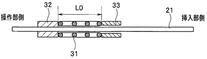
- FIG. 3 is a diagram showing a state of the urging mechanism when the bending portion 17 is in a straight state
- FIG. 4 is a first cable that is a long member with the bending portion 17 bent in the up (U) direction
- FIG. 5 is a diagram showing a state of the urging mechanism when 21 is extended to the insertion portion 3 side
- FIG. 5 shows a first cable 21 that is a long member with the bending portion 17 bent in the down (D) direction.
- the elastic member 31 is engaged with the first cable 21, which is a long member, at one end side and the other end side with the operation unit 2, and is positioned at a relative position between the first cable 21 and the operation unit 2.
- the urging force for pulling the first cable 21 of the corresponding size toward the operation unit 2 is exhibited.
- the elastic member 31 is configured as a coil spring (for example, a compression coil spring), and is inserted outside the first cable 21.
- the elastic member 31 bends the bending portion 17 in the direction (down (D) direction shown in FIG. 7) in which the first cable 21 that is a long member is disposed in the cross section of the insertion portion 3 perpendicular to the central axis.
- the elastic member exerts an urging force in any curved state in order to prevent the long member from being bent regardless of the curved state of the curved portion 17.
- the urging force asymptotically approaches 0 at the time of at least one maximum bending. From such a viewpoint, it is preferable that the natural state of the elastic member 31 is achieved when the bending portion 17 is bent to the maximum in the direction (D direction) in which the long member is disposed.
- FIG. 5 shows a bent end state in which the bending portion 17 is bent to the maximum in the D direction (the first cable 21 is moved most toward the operation portion 2 along the central axis direction of the insertion portion 3). ) Shows a state where the elastic member 31 configured as a coil spring has a natural length L0 which is a natural state.
- the elastic member 31 since the elastic member 31 is compressed in a state other than the state shown in FIG. 5, the elastic member 31 is also in a straight state where the bending operation as shown in FIG. The urging
- the range that x satisfies is 0 ⁇ x ⁇ (L0 ⁇ Lmin).
- the spring constant of the elastic member 31 is k
- the first locking member 32 locks one end side of the elastic member 31 to the first cable 21 which is a long member. That is, the 1st locking member 32 is being fixed to the 1st cable 21 which is a long member, for example, by inserting a heat contraction tube outside the 1st cable 21, and contracting it by adding heat. It is a configured ring-shaped member.
- the outer diameter of the first locking member 32 when attached to the outer periphery of the first cable 21 is approximately the same as the outer diameter of the elastic member 31 configured as a coil spring. Accordingly, it is possible to suppress the increase in diameter of the operation unit 2 as much as possible while reliably locking the one end side of the elastic member 31.
- the second locking member 33 is configured as a ring-shaped member whose inner diameter is slightly larger than the outer diameter of the first cable 21 and whose outer diameter is approximately the same as the outer diameter of the elastic member 31. For example, it is fixed to the operation unit main body 25.
- the second locking member 33 guides the first cable 21 on the inner peripheral side, and locks the other end side of the elastic member 31 to the operation unit 2.
- the elastic member 31 exerts an urging force according to the distance between the first locking member 32 and the second locking member 33.
- the first cable 21 is taken as an example of the long member provided with the urging mechanism.
- the second cable 22 and the third cable 23 which are other cables, or the light guide 24 and the channel 14 are used.
- An urging mechanism may be provided on the bending wire or the like, but not limited thereto, any flexible member may be used as long as it is a flexible long member disposed in the insertion portion 3 and extending into the operation portion 2.
- An urging mechanism can be provided.
- the elastic member 31 exerts a biasing force that pulls the long member toward the operation unit 2, so that the long member moves smoothly, no meandering occurs, and insertion by a bending operation is performed. Disturbance of the arrangement of the long members of the portion 3 can be suppressed.
- the elastic member 31 is in a natural state in which it does not exert a biasing force, so at least the direction in which the long member is arranged.
- the bending portion 17 is bent in the opposite direction and in the straight state, that is, in a range that is more than half of the bendable range including the straight state considered to have the longest use time, the long member is pulled toward the operation portion 2 side.
- the elastic member 31 is further substantially in the entire bendable range. Disturbance of arrangement can be suppressed. Therefore, the elastic member 31 that exhibits a necessary and sufficient urging force can be employed, which can contribute to the downsizing of the endoscope 1.
- the elastic member 31 is directly attached to the long member or the operation unit 2. Even if it is not fixed, it is possible to secure an action point at which both ends of the elastic member 31 apply a biasing force.
- the elastic member 31 as a coil spring, the elastic member 31 can be arranged using the space on the outer peripheral side of the long member evenly, and the arrangement space of the elastic member 31 is biased in a specific direction. It does not occur, and there is an advantage that it is not necessary to change the shape of the operation unit 2.
- the 1st locking member 32 and the 2nd locking member 33 are comprised as a ring-shaped member, like the elastic member 31 at the time of using a coil spring, the space on the outer peripheral side of a long member is used. Since it is possible to arrange them evenly, there is an advantage that it is not necessary to change the shape of the operation unit 2. At this time, since the second locking member 33 guides the long member on the inner peripheral side, it is possible to smoothly promote the movement of the long member along the central axis direction of the insertion portion 3.
- FIG. 6 and 7 show Embodiment 2 of the present invention
- FIG. 6 is a cross-sectional view showing the configuration of the operation portion of the endoscope
- FIG. 7 is an arrangement example of the built-in objects in the insertion portion of the endoscope.
- a plurality of urging mechanisms are provided for two or more of the plurality of long members.
- the long member group arranged on one end side and the long member group arranged on the other end side in a straight bending direction are collectively urged by one urging mechanism. Therefore, the number of urging mechanisms is two.
- the bending portion 17 is configured to be able to bend only in a straight line direction passing through the central axis of the insertion portion 3 in the cross section of the insertion portion 3 shown in FIG. Is curved only in two directions: one direction (referred to as the up (U) direction as shown in FIG. 7) and the opposite direction (also referred to as the down (D) direction). It is possible. These U direction and D direction are collectively referred to as a bendable direction as appropriate below.
- the arrangement of the built-in objects in the insertion section 3 is as shown in FIG. 7, and the channel 14, the first cable 21, the second cable 22, the third cable 23, and the light guide 24 are reversed in this order. Arranged clockwise.
- a dividing line that divides the insertion portion 3 into two, which is perpendicular to the bendable direction (U direction and D direction) and passes through the central axis of the insertion portion 3, is HH ′.
- Channel 14 is defined as a D region (first region) and a U region (second region) on the D direction side of the dividing line HH ′ of the two regions divided by For example, the channel centers are arranged on the dividing line HH ′.
- a plurality of other long members are separately provided in a first region and a second region, and the first cable 21 is connected to the D region (first region) in the second cable. 22, the third cable 23, and the light guide 24 are arranged in the U region (second region) so that their centers are located.
- the channel 14 has the largest diameter, so that bending is unlikely to occur.
- the light guide 24 is a fiber bundle configured by bundling a plurality of fibers, the light guide 24 is strong and hardly bends. Therefore, in the present embodiment, the first cable 21, the second cable 22, and the third cable 23 that are more flexible and easier to bend than the channel 14 and the light guide 24 are targets to be biased by the biasing mechanism. The long member is selected.
- the first cable 21 arranged in the region D (first region) among the plurality of long members to be biased is the same as that in the first embodiment. Similarly, it is urged by an urging mechanism (hereinafter referred to as a first urging mechanism as appropriate) provided with an elastic member 31, a first locking member 32, and a second locking member 33.
- a first urging mechanism as appropriate
- the second cable 22 and the third cable 23 arranged in the U region (second region) among the plurality of long members to be energized are the elastic member 31A and the first member.
- the urging mechanism 32A and the second locking member 33A are collectively urged by one urging mechanism (hereinafter, referred to as a second urging mechanism as appropriate).
- the first locking member 32 ⁇ / b> A is commonly fixed to the second cable 22 and the third cable 23.
- the second cable 22 and the third cable 23 are inserted into the second locking member 33A that is fixed to the operation unit body 25 and has, for example, an elliptical hole.
- An elastic member 31A through which the second cable 22 and the third cable 23 are inserted in common is disposed between the first locking member 32A and the second locking member 33A, and both ends are locked.
- the curved position where the elastic member 31A has a natural length is a position of the second cable 22 and the third cable 23 that is further separated from the dividing line HH ′ (that is, the central axis).
- the amount of movement in the direction is larger). That is, the extension length of the cable 23 toward the operating portion when the straight state is shifted to the maximum bending state in the U direction is the same as the compression amount x of the length of the elastic member 31A in the straight state.
- the attachment positions of the first locking member 32A and the second locking member 33A and the natural length of the elastic member 31A are determined.
- the first urging mechanism and the second urging mechanism are configured so that the position of the insertion portion 3 in the central axis direction does not overlap regardless of the bending state of the bending portion 17. As shown in FIG. 2, the positions in the central axis direction are shifted. More generally, when a plurality of urging mechanisms are provided, at least two of the urging mechanisms are arranged so that positions in the central axis direction do not overlap. Good (however, it is better if all the urging mechanisms are arranged so that their positions in the central axis direction do not overlap).
- the effects similar to those of the first embodiment described above can be obtained, and the plurality of urging mechanisms are arranged so that the positions in the direction of the central axis of the insertion portion 3 do not overlap. Thus, it is possible to suppress an increase in diameter of the operation unit 2.
- the bendable direction is only a straight line direction
- the plurality of long members to be biased are collectively biased in each of the two regions divided by the dividing line HH ′.
- the bending portion 17 of the long member having the largest movement amount in the central axis direction when the bending portion 17 is bent is maximized.
- the elastic member is configured to be in a natural state in which it does not exert an urging force in accordance with the amount of movement when it is bent in a curved line, so that excessive urging force is prevented (that is, the long member is fatigued as much as possible). It is possible to suppress the disorder of the arrangement of the plurality of long members.
- the present invention is not limited to the above-described embodiment as it is, and can be embodied by modifying the constituent elements without departing from the scope of the invention in the implementation stage.
- various aspects of the invention can be formed by appropriately combining a plurality of components disclosed in the embodiment. For example, you may delete some components from all the components shown by embodiment.
- the constituent elements over different embodiments may be appropriately combined.
Abstract
An endoscope comprising: an insertion portion (3) having a curve portion; an operational portion (2) which is coupled to the insertion portion (3); a cable (21) which is disposed inside the insertion portion (3) and operational portion (2); and an elastic member (31) which is locked at one end by the cable (21) and another end by the operational portion (2) and which pulls the cable (21) toward the operational portion (2). Curving the curve portion in an orientation of the cable (21) in a cross section vertical to an insertion axis causes the elastic member (31) to be in a natural state.
Description
本発明は、挿入部内に配設され操作部内へ延設される柔軟な長尺部材を備える内視鏡に関する。
The present invention relates to an endoscope including a flexible long member disposed in an insertion portion and extending into an operation portion.
内視鏡には、挿入位置を変更することなく対物レンズが配設された先端の方向を変化させることができるように、挿入部の先端側に湾曲可能な湾曲部を備えるものがある。こうした内視鏡は、例えば、操作部から挿入部へ延設される湾曲ワイヤを備えており、操作部において発生された湾曲操作の駆動力がこの湾曲ワイヤを介して伝達され、湾曲部の湾曲が行われるようになっている。
Some endoscopes include a bendable bending portion on the distal end side of the insertion portion so that the direction of the distal end where the objective lens is disposed can be changed without changing the insertion position. Such an endoscope includes, for example, a bending wire extending from the operation unit to the insertion unit, and the driving force of the bending operation generated in the operation unit is transmitted through the bending wire, so that the bending unit is bent. Is to be done.
こうしたワイヤに関連する技術として、例えば日本国特開平8-160317号公報に記載された内視鏡が挙げられる。この内視鏡は、操作機構を有する本体と、この本体から連設された、フレキシブルな挿入部、湾曲可能な湾曲部、および硬性チップと、を備える。操作機構のスライダには湾曲部を湾曲させるためのワイヤの後端が連結されており、このワイヤは、挿入部および湾曲部内を挿通されて、先端が硬性チップに固定されている。本体内におけるスライダの先端側には支持板が設けられ、この支持板とスライダとの間に、ワイヤを囲むように圧縮コイルスプリングが介在されている。ここに、コイルスプリングの力は、ワイヤの弛みをなくすために必要な強さで足り、湾曲部の湾曲操作の支障となる程強いものではない。このような構成により、スライダは常に後方に付勢されているために、湾曲操作時におけるワイヤ緊張を防ぐことができると共に、湾曲部が湾曲状態から直線状態に戻ったときに、スライダが後方に移動してワイヤの弛みをなくすことができ、疲労によるワイヤの断線を防止することができるとされている。
As a technique related to such a wire, for example, an endoscope described in Japanese Patent Laid-Open No. 8-160317 can be cited. This endoscope includes a main body having an operation mechanism, and a flexible insertion portion, a bendable bending portion, and a rigid tip that are connected to the main body. The rear end of a wire for bending the bending portion is connected to the slider of the operation mechanism, and this wire is inserted through the insertion portion and the bending portion, and the tip is fixed to the hard tip. A support plate is provided on the front end side of the slider in the body, and a compression coil spring is interposed between the support plate and the slider so as to surround the wire. Here, the force of the coil spring is sufficient to eliminate the slack of the wire, and is not so strong as to hinder the bending operation of the bending portion. With such a configuration, since the slider is always urged rearward, wire tension during the bending operation can be prevented, and when the bending portion returns from the curved state to the linear state, the slider moves backward. It is said that it can move and eliminate the slack of the wire, and can prevent the wire from being broken due to fatigue.
また、日本国特開平11-295616号公報には、体内や細管内等を観察する内視鏡の先端首振部を首振用ワイヤを介して首振させるために例えば用いられる光駆動型アクチュエータが記載されている。この光駆動型アクチュエータは、直線移動可能な可動部を挟んで配置された形状記憶ばね部およびバイアスばね部と、形状記憶ばね部に光を照射して加熱する加熱用光ファイバと、を備えている。
Japanese Patent Application Laid-Open No. 11-295616 discloses an optically driven actuator used, for example, for swinging the tip swing portion of an endoscope for observing the inside of a body or a thin tube through a swing wire. Is described. This light-driven actuator includes a shape memory spring portion and a bias spring portion arranged with a movable portion that can move linearly, and a heating optical fiber that irradiates and heats the shape memory spring portion. Yes.
さらに、内視鏡は、挿入部内に配設され操作部内へ延設される柔軟な長尺部材として、被検体を照明するための照明光を伝送するライトガイド(もしくは、内視鏡先端部に配設された照明用素子を発光するための照明用電力を伝達する照明用ケーブル)、撮像素子を含む撮像部へ接続される例えば複数の撮像ケーブル、処置具を挿通するためのチャンネル等を、内視鏡の機能に合わせてさらに備えることもある。これらの内蔵物は、それぞれが、蛇行することなく、かつ他のケーブルとクロスすることがないように、配列を整えて組み立てられている。
Furthermore, the endoscope is a flexible long member that is disposed in the insertion portion and extends into the operation portion, and a light guide that transmits illumination light for illuminating the subject (or the distal end portion of the endoscope). Illumination cable for transmitting illumination power for emitting light from the arranged illumination element), for example, a plurality of imaging cables connected to an imaging unit including the imaging element, a channel for inserting a treatment instrument, etc. It may be further provided in accordance with the function of the endoscope. These built-in items are arranged and assembled so that each does not meander and cross with other cables.
しかし、組立後の使用時に湾曲操作が行われると、内視鏡の内部(特に、湾曲部の内部)において長尺部材が挿入部の中心軸方向に進退するが、内蔵物の充填率が高い場合には長尺部材同士に摩擦力が発生すること、長尺部材が細径である場合には腰が弱く屈曲し易いこと、などから、長尺部材が操作部側にスムーズに移動することができずに蛇行が発生してしまうことがある。この蛇行によって生じたスペースに、蛇行が発生した長尺部材にクロスするように他の長尺部材が入り込むと、複数の長尺部材の配置に入れ替えが発生する。このような長尺部材の配置の乱れが生じると、配置状況によっては、その後の湾曲時において、長尺部材の移動が阻害される、あるいは長尺部材同士がクロスしている部分で長尺部材の損傷が発生することなどが考えられる。従って、こうした長尺部材の配置の乱れをできるだけ抑制することが望まれている。
However, if a bending operation is performed at the time of use after assembly, the long member moves forward and backward in the central axis direction of the insertion portion inside the endoscope (in particular, inside the bending portion), but the filling rate of the built-in objects is high. In some cases, the frictional force is generated between the long members, and when the long member has a small diameter, the waist is weak and easy to bend. Sometimes, meandering occurs. If another long member enters the space generated by the meander so as to cross the long member where the meander has occurred, the arrangement of the plurality of long members is changed. When such an arrangement of the long member is disturbed, depending on the arrangement state, the movement of the long member is hindered during subsequent bending, or the long member is crossed between the long members. It is possible that damage will occur. Therefore, it is desired to suppress such disturbance of the arrangement of the long members as much as possible.
また、上記日本国特開平8-160317号公報に記載された技術は、硬性チップを牽引するためのワイヤをコイルスプリングにより引張する技術、つまり、引っ張り強度を元々備えているワイヤを対象とした技術であったために、ワイヤが常に付勢されていたとしても特に支障は生じなかったが、上述した撮像ケーブル、ライトガイド、照明用ケーブル、チャンネル等は引張されることを想定した長尺部材ではないために、該公報に記載に技術を仮にそのまま適用したとしても長尺部材の疲労が大きくなってしまう可能性がある。
Further, the technique described in the above Japanese Patent Laid-Open No. 8-160317 is a technique for pulling a wire for pulling a hard tip with a coil spring, that is, a technique for a wire originally having a tensile strength. Therefore, even if the wire was always energized, there was no problem, but the above-described imaging cable, light guide, lighting cable, channel, etc. are not long members that are assumed to be pulled. Therefore, even if the technique described in the publication is applied as it is, the fatigue of the long member may be increased.
本発明は上記事情に鑑みてなされたものであり、湾曲操作による挿入部の長尺部材の配置の乱れを、長尺部材の疲労をなるべく軽減しながら抑制することができる内視鏡を提供することを目的としている。
The present invention has been made in view of the above circumstances, and provides an endoscope capable of suppressing disturbance of the arrangement of the long member of the insertion portion due to a bending operation while reducing fatigue of the long member as much as possible. The purpose is that.
本発明のある態様による内視鏡は、湾曲可能な湾曲部を有する長尺の挿入部と、前記挿入部の基端側に連設された操作部と、前記挿入部内に配設され、前記操作部内へ延設される柔軟な長尺部材と、前記長尺部材に一端側を、前記操作部に他端側を、それぞれ係止され、前記長尺部材と前記操作部との相対的な位置に応じた大きさの、前記長尺部材を前記操作部側へ引張する付勢力を発揮する弾性部材と、を備え、前記長尺部材は、前記挿入部の中心軸に垂直な挿入部断面において該中心軸に対して偏心して配置され、該長尺部材が配置された方向へ前記湾曲部を湾曲させたときに、前記弾性部材が付勢力を発揮しない自然状態となるように構成されている。
An endoscope according to an aspect of the present invention is provided with a long insertion portion having a bendable bending portion, an operation portion connected to a proximal end side of the insertion portion, and the insertion portion. A flexible elongate member extending into the operation unit, one end side of the elongate member, and the other end side of the operation unit are engaged with each other, and the long member and the operation unit are relatively An elastic member that exerts an urging force that pulls the long member to the operation unit side in a size according to a position, and the long member is a section of the insertion unit perpendicular to the central axis of the insertion unit The elastic member is arranged in a natural state where the elastic member does not exert an urging force when the bending portion is bent in the direction in which the long member is arranged. Yes.
以下、図面を参照して本発明の実施の形態を説明する。
Hereinafter, embodiments of the present invention will be described with reference to the drawings.
[実施形態1]
図1から図5は本発明の実施形態1を示したものであり、図1は内視鏡1を示す斜視図である。 [Embodiment 1]
1 to 5 show a first embodiment of the present invention, and FIG. 1 is a perspective view showing anendoscope 1.
図1から図5は本発明の実施形態1を示したものであり、図1は内視鏡1を示す斜視図である。 [Embodiment 1]
1 to 5 show a first embodiment of the present invention, and FIG. 1 is a perspective view showing an
図1に示すように、内視鏡1は、例えば電子内視鏡として構成されていて、被検体内に挿入されるようになされた細径で長尺の挿入部3と、この挿入部3の基端側に連設された操作部2と、この操作部2の基端側から側方へ延設されたユニバーサルケーブル4と、を備えている。
As shown in FIG. 1, an endoscope 1 is configured as an electronic endoscope, for example, and has a thin and long insertion portion 3 that is configured to be inserted into a subject, and the insertion portion 3. The operation unit 2 connected to the base end side of the control unit 2 and a universal cable 4 extending from the base end side of the operation unit 2 to the side are provided.
操作部2は、操作者が把持するための把持部11と、把持部11を把持した手の例えば親指等により湾曲操作可能な例えば回転操作式の湾曲レバー12と、例えばフリーズ操作などの撮像に関する操作を行うための操作ボタン13と、処置具を挿通するためのチャンネル14の基端側開口と、テーパ形状をなし挿入部3の屈曲を防止するための折止部15と、を備えている。また、図2に示すように、操作部2の内部には、操作部2の枠組みとなる操作部本体25が設けられている。
The operation unit 2 is related to imaging such as a gripping unit 11 for an operator to grip, a bending lever 12 that can be bent by, for example, a thumb of a hand that holds the gripping unit 11, and a freeze operation, for example. An operation button 13 for performing the operation, a proximal end side opening of the channel 14 for inserting the treatment instrument, and a folding portion 15 for forming a tapered shape and preventing the insertion portion 3 from bending are provided. . As shown in FIG. 2, an operation unit main body 25 that is a framework of the operation unit 2 is provided inside the operation unit 2.
挿入部3は、基端側から先端側へ向かって順に、長尺で可撓性を備える可撓管部16と、上述した湾曲レバー12の操作によって湾曲される湾曲可能な湾曲部17と、撮像素子を含む撮像部や対物光学系が設けられた先端硬性部18と、を備えている。
The insertion portion 3 is, in order from the proximal end side to the distal end side, a long and flexible flexible tube portion 16, a bendable bending portion 17 that is bent by the operation of the bending lever 12 described above, An image pickup unit including an image pickup element, and a distal end rigid portion 18 provided with an objective optical system.
ユニバーサルケーブル4は、図2に示すような、挿入部3内の撮像部へ接続される第1のケーブル21、第2のケーブル22、および第3のケーブル23と、挿入部3の先端から被検体へ照射される照明光を伝送するライトガイド24(後述する実施形態2の図7参照)と、が挿通されていて、これらの基端側を図示しないビデオプロセッサや光源装置等へ接続するためのものである。
As shown in FIG. 2, the universal cable 4 includes a first cable 21, a second cable 22, and a third cable 23 that are connected to the imaging unit in the insertion unit 3, and a distal end of the insertion unit 3. A light guide 24 (see FIG. 7 of Embodiment 2 to be described later) for transmitting illumination light irradiated to the specimen is inserted, and the base end side thereof is connected to a video processor, a light source device or the like (not shown). belongs to.
次に、本実施形態の内視鏡1においては、挿入部3内に配設され、操作部2内へ延設される柔軟な長尺部材として、図7も参照すれば分かるように、上述したチャンネル14と、第1のケーブル21と、第2のケーブル22と、第3のケーブル23と、ライトガイド24と、が設けられている。さらに、図示はしないが、湾曲レバー12の操作により湾曲部17の先端側を牽引して湾曲部17を湾曲させるための湾曲ワイヤも、挿入部3内に配設され、操作部2内へ延設される柔軟な長尺部材の1つである。これらの長尺部材は、挿入部3の中心軸に垂直な挿入部3の断面において、中心軸に対して偏心して配置されている。湾曲状態にある湾曲部17は内径側と外径側とでカーブに沿った長さが異なるために、挿入部3内に偏心して配設された長尺部材は、湾曲操作によって挿入部3の中心軸方向に移動することになる。
Next, in the endoscope 1 of the present embodiment, as described with reference to FIG. 7, the flexible long member disposed in the insertion portion 3 and extending into the operation portion 2 is described above. The channel 14, the first cable 21, the second cable 22, the third cable 23, and the light guide 24 are provided. Further, although not shown, a bending wire for bending the bending portion 17 by pulling the distal end side of the bending portion 17 by operating the bending lever 12 is also disposed in the insertion portion 3 and extends into the operation portion 2. It is one of the flexible long members provided. These long members are arranged eccentrically with respect to the central axis in the cross section of the insertion part 3 perpendicular to the central axis of the insertion part 3. Since the curved portion 17 in the curved state has different lengths along the curve on the inner diameter side and the outer diameter side, the long member arranged eccentrically in the insertion portion 3 is deformed by the bending operation. It moves in the direction of the central axis.
例えば、中心軸に垂直な挿入部3の断面(図7参照)において、ダウン(D)方向に配置された長尺部材である第1のケーブル21は、D方向へ湾曲部17を湾曲させるダウン操作により挿入部3から操作部2側へ移動し、D方向の反対方向(図7に示すアップ(U)方向)へ湾曲部17を湾曲させるアップ操作により操作部2から挿入部3側へ移動する。このとき、第1のケーブル21は、ダウン操作時には後述する弾性部材31の付勢力により挿入部3から操作部2内に引き込まれ、アップ操作時には弾性部材31の付勢力に抗して加えられる湾曲ワイヤの牽引力により操作部2から挿入部3へ繰り出される。
For example, in the cross section of the insertion portion 3 perpendicular to the central axis (see FIG. 7), the first cable 21 that is a long member disposed in the down (D) direction is a down that curves the bending portion 17 in the D direction. The operation unit moves from the insertion unit 3 to the operation unit 2 side, and moves from the operation unit 2 to the insertion unit 3 side by an up operation of bending the bending unit 17 in the direction opposite to the D direction (up (U) direction shown in FIG. 7) To do. At this time, the first cable 21 is pulled into the operation unit 2 from the insertion portion 3 by an urging force of an elastic member 31 described later during a down operation, and is bent against the urging force of the elastic member 31 during an up operation. The wire is pulled out from the operation unit 2 to the insertion unit 3 by the pulling force of the wire.
そして、複数の長尺部材の内の少なくとも1つの長尺部材、本実施形態においては図2に示すように例えば第1のケーブル21に、弾性部材31と第1係止部材32と第2係止部材33とを備えた付勢機構が設けられている。
Then, at least one long member among the plurality of long members, in this embodiment, for example, as shown in FIG. 2, for example, the first cable 21, the elastic member 31, the first locking member 32, and the second member. An urging mechanism including a stop member 33 is provided.
この付勢機構は、例えば、図3~図5に示すように構成されている。ここに、図3は湾曲部17がストレート状態にあるときの付勢機構の様子を示す図、図4は湾曲部17がアップ(U)方向へ湾曲され、長尺部材である第1のケーブル21が挿入部3側へ繰り出された状態にあるときの付勢機構の様子を示す図、図5は湾曲部17がダウン(D)方向へ湾曲され、長尺部材である第1のケーブル21が操作部2側へ引き戻された状態にあるときの付勢機構の様子を示す図である。なお、図3~図5においては、図2と同様に、左側が基端側(操作部側)、右側が先端側(挿入部側)となっている。
This urging mechanism is configured as shown in FIGS. 3 to 5, for example. FIG. 3 is a diagram showing a state of the urging mechanism when the bending portion 17 is in a straight state, and FIG. 4 is a first cable that is a long member with the bending portion 17 bent in the up (U) direction. FIG. 5 is a diagram showing a state of the urging mechanism when 21 is extended to the insertion portion 3 side, and FIG. 5 shows a first cable 21 that is a long member with the bending portion 17 bent in the down (D) direction. It is a figure which shows the mode of the urging | biasing mechanism when it is in the state pulled back to the operation part 2 side. 3 to 5, as in FIG. 2, the left side is the base end side (operation unit side), and the right side is the front end side (insertion unit side).
弾性部材31は、長尺部材である第1のケーブル21に一端側を、操作部2に他端側を、それぞれ係止され、第1のケーブル21と操作部2との相対的な位置に応じた大きさの、第1のケーブル21を操作部2側へ引張する付勢力を発揮するものである。具体的に弾性部材31は、コイルばね(例えば圧縮コイルばね)として構成されていて、第1のケーブル21の外側に挿通されている。
The elastic member 31 is engaged with the first cable 21, which is a long member, at one end side and the other end side with the operation unit 2, and is positioned at a relative position between the first cable 21 and the operation unit 2. The urging force for pulling the first cable 21 of the corresponding size toward the operation unit 2 is exhibited. Specifically, the elastic member 31 is configured as a coil spring (for example, a compression coil spring), and is inserted outside the first cable 21.
この弾性部材31は、中心軸に垂直な挿入部3の断面において長尺部材である第1のケーブル21が配置された方向(図7に示すダウン(D)方向)へ湾曲部17を湾曲させたときに、第1のケーブル21が操作部2側へ引き戻されることに伴って、付勢力を発揮しない自然状態となるように構成されている。ここに、湾曲部17がどのような湾曲状態であっても長尺部材に屈曲が発生しないようにするためには、任意の湾曲状態において弾性部材が付勢力を発揮することが好ましい。一方、長尺部材に過剰な付勢力が作用しないようにするためには、少なくとも1つの最大湾曲時に付勢力が0に漸近することが好ましい。このような観点から、弾性部材31の自然状態が、長尺部材が配置された方向(D方向)へ湾曲部17を最大に湾曲させたときに達成されるように構成すると良い。
The elastic member 31 bends the bending portion 17 in the direction (down (D) direction shown in FIG. 7) in which the first cable 21 that is a long member is disposed in the cross section of the insertion portion 3 perpendicular to the central axis. When the first cable 21 is pulled back to the operation unit 2 side, it is configured to be in a natural state where no urging force is exerted. Here, it is preferable that the elastic member exerts an urging force in any curved state in order to prevent the long member from being bent regardless of the curved state of the curved portion 17. On the other hand, in order to prevent an excessive urging force from acting on the long member, it is preferable that the urging force asymptotically approaches 0 at the time of at least one maximum bending. From such a viewpoint, it is preferable that the natural state of the elastic member 31 is achieved when the bending portion 17 is bent to the maximum in the direction (D direction) in which the long member is disposed.
具体的に図5は、湾曲部17がD方向へ最大に湾曲されたとき(第1のケーブル21が挿入部3の中心軸方向に沿って最も操作部2側に移動している湾曲端状態のとき)に、コイルばねとして構成されている弾性部材31が、自然状態である自然長L0をとっている状態を示している。
Specifically, FIG. 5 shows a bent end state in which the bending portion 17 is bent to the maximum in the D direction (the first cable 21 is moved most toward the operation portion 2 along the central axis direction of the insertion portion 3). ) Shows a state where the elastic member 31 configured as a coil spring has a natural length L0 which is a natural state.
一方、弾性部材31は図5に示す状態以外の状態においては圧縮されていることになるために、この弾性部材31は、例えば図3に示すような湾曲操作がなされていないストレート状態においても、第1のケーブル21に引張される付勢力を与えている。
On the other hand, since the elastic member 31 is compressed in a state other than the state shown in FIG. 5, the elastic member 31 is also in a straight state where the bending operation as shown in FIG. The urging | biasing force pulled by the 1st cable 21 is given.
弾性部材31の長さの圧縮分をxとすれば、弾性部材31の長さLは、L=(L0-x)と表すことができる。ここに、弾性部材31が最も圧縮されたときの最短長さをLminとし、弾性部材31が圧縮状態および自然状態のみをとって引張状態をとらないとすれば、xが満たす範囲は0≦x≦(L0-Lmin)である。
If the compression of the length of the elastic member 31 is x, the length L of the elastic member 31 can be expressed as L = (L0−x). Here, if the shortest length when the elastic member 31 is most compressed is Lmin, and the elastic member 31 takes only the compressed state and the natural state and does not take the tensile state, the range that x satisfies is 0 ≦ x ≦ (L0−Lmin).
そして、図4は、湾曲部17が図7に示すアップ(U)方向へ最大に湾曲されたときに、例えばx=xmax=(L0-Lmin)となったときの状態を示している。
FIG. 4 shows a state in which, for example, x = xmax = (L0−Lmin) is obtained when the bending portion 17 is bent to the maximum in the up (U) direction shown in FIG.
ところで、弾性部材31のばね定数をkとすると、弾性部材31から第1のケーブル21に作用する付勢力Fは、F=k×xとなる。従って、第1のケーブル21を引張したときに破断に至る可能性があると考えられる破断力量をFmaxとすると、第1のケーブル21が破断しないようにするためには、k<(Fmax/xmax)={Fmax/(L0-Lmin)}を満たすようなばね定数kの弾性部材31を選択することが必要である。このとき実用上は、上述したばね定数kの範囲内において、さらに第1のケーブル21に引張力に起因する疲労や消耗が生じ難いような、かつ、挿入部3の内蔵物同士の摩擦力に抗して第1のケーブル21を引張することができるような、適切なばね定数kの弾性部材31を選択して用いると良い。
By the way, when the spring constant of the elastic member 31 is k, the urging force F acting on the first cable 21 from the elastic member 31 is F = k × x. Accordingly, if the breaking force amount that is considered to possibly break when the first cable 21 is pulled is Fmax, k <(Fmax / xmax) in order to prevent the first cable 21 from breaking. ) = {Fmax / (L0−Lmin)} It is necessary to select the elastic member 31 having a spring constant k. At this time, practically, within the range of the spring constant k described above, the first cable 21 is less likely to be fatigued or consumed due to the tensile force, and the frictional force between the built-in components of the insertion portion 3 is reduced. It is preferable to select and use an elastic member 31 having an appropriate spring constant k that can pull the first cable 21 against it.
第1係止部材32は、弾性部材31の一端側を、長尺部材である第1のケーブル21に対して係止するものである。すなわち、第1係止部材32は、長尺部材である第1のケーブル21に固定されており、例えば熱収縮チューブを第1のケーブル21の外側に挿通した後に熱を加えて収縮させることにより構成されたリング状の部材である。ここに第1係止部材32は、第1のケーブル21の外周に取り付けたときの外径が、コイルばねとして構成された弾性部材31の外径と同程度となることが好ましい。これにより、弾性部材31の一端側の係止を確実に行いながら、操作部2の大径化をなるべく抑制することができる。
The first locking member 32 locks one end side of the elastic member 31 to the first cable 21 which is a long member. That is, the 1st locking member 32 is being fixed to the 1st cable 21 which is a long member, for example, by inserting a heat contraction tube outside the 1st cable 21, and contracting it by adding heat. It is a configured ring-shaped member. Here, it is preferable that the outer diameter of the first locking member 32 when attached to the outer periphery of the first cable 21 is approximately the same as the outer diameter of the elastic member 31 configured as a coil spring. Accordingly, it is possible to suppress the increase in diameter of the operation unit 2 as much as possible while reliably locking the one end side of the elastic member 31.
第2係止部材33は、内径が第1のケーブル21の外径よりも僅かに大きい程度、外径が弾性部材31の外径と同程度のリング状の部材として構成され、操作部2の例えば操作部本体25に対して固定されている。この第2係止部材33は、内周側において第1のケーブル21を案内すると共に、弾性部材31の他端側を操作部2に対して係止するものとなっている。
The second locking member 33 is configured as a ring-shaped member whose inner diameter is slightly larger than the outer diameter of the first cable 21 and whose outer diameter is approximately the same as the outer diameter of the elastic member 31. For example, it is fixed to the operation unit main body 25. The second locking member 33 guides the first cable 21 on the inner peripheral side, and locks the other end side of the elastic member 31 to the operation unit 2.
このような構成により、弾性部材31は、第1係止部材32と第2係止部材33との距離に応じて付勢力を発揮することになる。
With such a configuration, the elastic member 31 exerts an urging force according to the distance between the first locking member 32 and the second locking member 33.
なお、上述では付勢機構を設ける長尺部材として第1のケーブル21を例に挙げたが、他のケーブルである第2のケーブル22や第3のケーブル23、あるいは、ライトガイド24、チャンネル14、湾曲ワイヤなどに付勢機構を設けても構わないし、これらに限らず、挿入部3内に配設され操作部2内へ延設される柔軟な長尺部材であれば、任意の部材に付勢機構を設けることが可能である。
In the above description, the first cable 21 is taken as an example of the long member provided with the urging mechanism. However, the second cable 22 and the third cable 23 which are other cables, or the light guide 24 and the channel 14 are used. An urging mechanism may be provided on the bending wire or the like, but not limited thereto, any flexible member may be used as long as it is a flexible long member disposed in the insertion portion 3 and extending into the operation portion 2. An urging mechanism can be provided.
このような実施形態1によれば、弾性部材31が長尺部材を操作部2側へ引張する付勢力を発揮するために長尺部材がスムーズに移動し、蛇行が生じず、湾曲操作による挿入部3の長尺部材の配置の乱れを抑制することができる。
According to the first embodiment, the elastic member 31 exerts a biasing force that pulls the long member toward the operation unit 2, so that the long member moves smoothly, no meandering occurs, and insertion by a bending operation is performed. Disturbance of the arrangement of the long members of the portion 3 can be suppressed.
さらに、長尺部材が配置された方向へ湾曲部17を湾曲させたときに、弾性部材31が付勢力を発揮しない自然状態となるように構成したために、少なくとも、長尺部材が配置された方向の逆方向へ湾曲部17を湾曲させたときおよびストレート状態において、つまり、最も使用時間が長いと考えられるストレート状態を含む湾曲可能範囲の半分以上の範囲において長尺部材が操作部2側へ引張されることとなり、配置の乱れを実効的に抑制することができると共に、長尺部材に過剰な付勢力が作用するのを防止し、ひいては引張による長尺部材の疲労をなるべく軽減することが可能となる。
Further, when the bending portion 17 is bent in the direction in which the long member is arranged, the elastic member 31 is in a natural state in which it does not exert a biasing force, so at least the direction in which the long member is arranged. When the bending portion 17 is bent in the opposite direction and in the straight state, that is, in a range that is more than half of the bendable range including the straight state considered to have the longest use time, the long member is pulled toward the operation portion 2 side. As a result, it is possible to effectively suppress the disturbance of the arrangement, to prevent the excessive biasing force from acting on the long member, and to reduce the fatigue of the long member due to tension as much as possible. It becomes.
このとき、弾性部材31の自然状態を、長尺部材が配置された方向へ湾曲部17を最大に湾曲させたときに達成するように構成すれば、さらに、実質的に湾曲可能範囲の全てにおいて配置の乱れを抑制することができる。従って、必要十分な付勢力を発揮する弾性部材31を採用することができ、内視鏡1の小型化にも寄与することができる。
At this time, if it is configured to achieve the natural state of the elastic member 31 when the bending portion 17 is bent to the maximum in the direction in which the long member is disposed, the elastic member 31 is further substantially in the entire bendable range. Disturbance of arrangement can be suppressed. Therefore, the elastic member 31 that exhibits a necessary and sufficient urging force can be employed, which can contribute to the downsizing of the endoscope 1.
また、長尺部材に固定された第1係止部材32と、操作部2に固定された第2係止部材33と、を設けたために、弾性部材31を長尺部材や操作部2に直接固定しなくても、弾性部材31の両端が付勢力を作用させる作用点を確保することができる。
In addition, since the first locking member 32 fixed to the long member and the second locking member 33 fixed to the operation unit 2 are provided, the elastic member 31 is directly attached to the long member or the operation unit 2. Even if it is not fixed, it is possible to secure an action point at which both ends of the elastic member 31 apply a biasing force.
加えて、弾性部材31をコイルばねとすることにより、長尺部材の外周側の空間を均等に用いて弾性部材31を配置することが可能となり、弾性部材31の配置スペースに特定方向の偏りが生じることはなく、ひいては操作部2の形状を変形させる必要がない利点がある。
In addition, by using the elastic member 31 as a coil spring, the elastic member 31 can be arranged using the space on the outer peripheral side of the long member evenly, and the arrangement space of the elastic member 31 is biased in a specific direction. It does not occur, and there is an advantage that it is not necessary to change the shape of the operation unit 2.
また、第1係止部材32および第2係止部材33をリング状の部材として構成した場合には、コイルばねを用いた場合の弾性部材31と同様に、長尺部材の外周側の空間を均等に用いた配置が可能となるために、操作部2の形状を変形させる必要がない利点が得られる。このときさらに、第2係止部材33は内周側において長尺部材を案内するために、挿入部3の中心軸方向に沿った長尺部材の移動を円滑に促すことが可能となる。
Moreover, when the 1st locking member 32 and the 2nd locking member 33 are comprised as a ring-shaped member, like the elastic member 31 at the time of using a coil spring, the space on the outer peripheral side of a long member is used. Since it is possible to arrange them evenly, there is an advantage that it is not necessary to change the shape of the operation unit 2. At this time, since the second locking member 33 guides the long member on the inner peripheral side, it is possible to smoothly promote the movement of the long member along the central axis direction of the insertion portion 3.
[実施形態2]
図6および図7は本発明の実施形態2を示したものであり、図6は内視鏡の操作部の構成を示す断面図、図7は内視鏡の挿入部内における内蔵物の配置例を示す断面図である。 [Embodiment 2]
6 and 7show Embodiment 2 of the present invention, FIG. 6 is a cross-sectional view showing the configuration of the operation portion of the endoscope, and FIG. 7 is an arrangement example of the built-in objects in the insertion portion of the endoscope. FIG.
図6および図7は本発明の実施形態2を示したものであり、図6は内視鏡の操作部の構成を示す断面図、図7は内視鏡の挿入部内における内蔵物の配置例を示す断面図である。 [Embodiment 2]
6 and 7
この実施形態2において、上述の実施形態1と同様である部分については同一の符号を付すなどして説明を適宜省略し、主として異なる点についてのみ説明する。
In the second embodiment, the same parts as those in the first embodiment are denoted by the same reference numerals and the description thereof is omitted as appropriate, and only different points will be mainly described.
本実施形態は、複数の長尺部材の内の2つ以上に対して複数の付勢機構を設けたものとなっている。特に本実施形態においては、一直線をなす湾曲方向における、一端側に配置された長尺部材群と他端側に配置された長尺部材群とを各まとめてそれぞれ1つの付勢機構により付勢するようにしており、従って、付勢機構の数は2つとなっている。
In the present embodiment, a plurality of urging mechanisms are provided for two or more of the plurality of long members. In particular, in the present embodiment, the long member group arranged on one end side and the long member group arranged on the other end side in a straight bending direction are collectively urged by one urging mechanism. Therefore, the number of urging mechanisms is two.
まず、本実施形態においては、湾曲部17は、図7に示す挿入部3の断面において、挿入部3の中心軸を通る一直線方向にのみ湾曲可能となるように構成されていて、具体的には、一方向(図7に示すように、アップ(U)方向ということにする)とこの一方向の反対方向(同様に、ダウン(D)方向ということにする)との2方向にのみ湾曲可能となっている。これらU方向およびD方向をまとめて、以下では適宜、湾曲可能方向ということにする。
First, in the present embodiment, the bending portion 17 is configured to be able to bend only in a straight line direction passing through the central axis of the insertion portion 3 in the cross section of the insertion portion 3 shown in FIG. Is curved only in two directions: one direction (referred to as the up (U) direction as shown in FIG. 7) and the opposite direction (also referred to as the down (D) direction). It is possible. These U direction and D direction are collectively referred to as a bendable direction as appropriate below.
挿入部3における内蔵物の配置は、図7に示すようになっており、チャンネル14、第1のケーブル21、第2のケーブル22、第3のケーブル23、およびライトガイド24が、この順に反時計回りに配置されている。
The arrangement of the built-in objects in the insertion section 3 is as shown in FIG. 7, and the channel 14, the first cable 21, the second cable 22, the third cable 23, and the light guide 24 are reversed in this order. Arranged clockwise.
挿入部3を2分割する区分線であって、湾曲可能方向(U方向およびD方向)に直交し挿入部3の中心軸を通る区分線をH-H’とし、この区分線H-H’により区分される2つの領域の内の、区分線H-H’よりもD方向側をD領域(第1の領域)、U方向側をU領域(第2の領域)とすると、チャンネル14はチャンネル中心が例えば区分線H-H’上に位置するように配置されている。また、それ以外の複数の長尺部材は第1の領域と第2の領域とに分かれて配設されており、第1のケーブル21はD領域(第1の領域)に、第2のケーブル22、第3のケーブル23、およびライトガイド24はU領域(第2の領域)に、それぞれの中心が位置するように配置されている。
A dividing line that divides the insertion portion 3 into two, which is perpendicular to the bendable direction (U direction and D direction) and passes through the central axis of the insertion portion 3, is HH ′. Channel 14 is defined as a D region (first region) and a U region (second region) on the D direction side of the dividing line HH ′ of the two regions divided by For example, the channel centers are arranged on the dividing line HH ′. In addition, a plurality of other long members are separately provided in a first region and a second region, and the first cable 21 is connected to the D region (first region) in the second cable. 22, the third cable 23, and the light guide 24 are arranged in the U region (second region) so that their centers are located.
挿入部3の内蔵物である上述した複数の長尺部材の内の、チャンネル14は、最も大径であるために屈曲が生じ難い。また、ライトガイド24は、複数のファイバを束ねて構成されたファイババンドルであるために、腰が強く屈曲が生じ難い。そこで、本実施形態においては、チャンネル14やライトガイド24よりも柔軟で屈曲し易い第1のケーブル21、第2のケーブル22、および第3のケーブル23を、付勢機構により付勢を行う対象の長尺部材として選択するものとする。
Of the plurality of elongate members described above, which are built-in parts of the insertion portion 3, the channel 14 has the largest diameter, so that bending is unlikely to occur. Further, since the light guide 24 is a fiber bundle configured by bundling a plurality of fibers, the light guide 24 is strong and hardly bends. Therefore, in the present embodiment, the first cable 21, the second cable 22, and the third cable 23 that are more flexible and easier to bend than the channel 14 and the light guide 24 are targets to be biased by the biasing mechanism. The long member is selected.
このとき図6に示すように、付勢対象となった複数の長尺部材の内の、D領域(第1の領域)に配置されている第1のケーブル21は、上述した実施形態1と同様に、弾性部材31と第1係止部材32と第2係止部材33とを備えた付勢機構(以下では適宜、第1の付勢機構という)により付勢される。
At this time, as shown in FIG. 6, the first cable 21 arranged in the region D (first region) among the plurality of long members to be biased is the same as that in the first embodiment. Similarly, it is urged by an urging mechanism (hereinafter referred to as a first urging mechanism as appropriate) provided with an elastic member 31, a first locking member 32, and a second locking member 33.
一方、付勢対象となった複数の長尺部材の内の、U領域(第2の領域)に配置されている第2のケーブル22および第3のケーブル23は、弾性部材31Aと第1係止部材32Aと第2係止部材33Aとを備えた1つの付勢機構(以下では適宜、第2の付勢機構という)によりまとめて付勢されるようになっている。
On the other hand, the second cable 22 and the third cable 23 arranged in the U region (second region) among the plurality of long members to be energized are the elastic member 31A and the first member. The urging mechanism 32A and the second locking member 33A are collectively urged by one urging mechanism (hereinafter, referred to as a second urging mechanism as appropriate).
すなわち、第2のケーブル22および第3のケーブル23には、第1係止部材32Aが共通して固定される。また、第2のケーブル22および第3のケーブル23は、操作部本体25に固定され例えば楕円状の孔を有する第2係止部材33Aに対して共通に挿通される。そして、第2のケーブル22および第3のケーブル23が共通して挿通される弾性部材31Aが、第1係止部材32Aと第2係止部材33Aとの間に配置され、両端が係止される。
That is, the first locking member 32 </ b> A is commonly fixed to the second cable 22 and the third cable 23. In addition, the second cable 22 and the third cable 23 are inserted into the second locking member 33A that is fixed to the operation unit body 25 and has, for example, an elliptical hole. An elastic member 31A through which the second cable 22 and the third cable 23 are inserted in common is disposed between the first locking member 32A and the second locking member 33A, and both ends are locked. The
このような構成において、1つの付勢機構により付勢される長尺部材が複数である場合には、湾曲部17を湾曲させたときの中心軸方向の移動量が最も大きい長尺部材の、湾曲部17を最大に湾曲させたときの移動量に合わせて、弾性部材31が付勢力を発揮しない自然状態となるための構成が決定されている。
In such a configuration, when there are a plurality of elongate members urged by one urging mechanism, the elongate member having the largest amount of movement in the central axis direction when the bending portion 17 is bent, In accordance with the amount of movement when the bending portion 17 is bent to the maximum, the configuration for the elastic member 31 to be in a natural state in which no urging force is exerted is determined.
具体的に、弾性部材31Aが自然長となる湾曲位置は、第2のケーブル22と第3のケーブル23との内の、区分線H-H’からより隔離した位置にある(つまり、中心軸方向の移動量がより大きい)ケーブル23に合わせて決められている。すなわち、ストレート状態からU方向の最大湾曲状態へ移行する際のケーブル23の操作部側への繰り出し長さが、ストレート状態における弾性部材31Aの長さの圧縮分xと同一となるように、第1係止部材32Aおよび第2係止部材33Aの取付位置と弾性部材31Aの自然長とが決定されている。これにより、長尺部材に過剰な付勢力が作用するのを防止し、ひいては引張による長尺部材の疲労をなるべく軽減することができると共に、実質的に湾曲可能範囲の全てにおいて第2のケーブル22および第3のケーブル23に付勢力が作用することになるために、第2のケーブル22と第3のケーブル23との両方の配置の乱れを効果的に抑制することが可能となる。
Specifically, the curved position where the elastic member 31A has a natural length is a position of the second cable 22 and the third cable 23 that is further separated from the dividing line HH ′ (that is, the central axis). The amount of movement in the direction is larger). That is, the extension length of the cable 23 toward the operating portion when the straight state is shifted to the maximum bending state in the U direction is the same as the compression amount x of the length of the elastic member 31A in the straight state. The attachment positions of the first locking member 32A and the second locking member 33A and the natural length of the elastic member 31A are determined. Accordingly, it is possible to prevent an excessive urging force from acting on the long member, thereby reducing fatigue of the long member due to tension as much as possible, and to substantially reduce the second cable 22 in the entire bendable range. Since the urging force acts on the third cable 23, it is possible to effectively suppress disturbance in the arrangement of both the second cable 22 and the third cable 23.
さらに、第1の付勢機構と第2の付勢機構とは、湾曲部17がどのような湾曲状態をとっていても、挿入部3の中心軸方向における位置が重複しないように、図6に示すように、中心軸方向の位置をずらして配設されている。より一般に、複数の付勢機構が設けられている場合には、これら複数の付勢機構の内の少なくとも2つの付勢機構が、中心軸方向における位置が重複しないように配設されていれば良い(ただし、全ての付勢機構が、中心軸方向における位置が重複しないように配設されているともっと良い)。
Furthermore, the first urging mechanism and the second urging mechanism are configured so that the position of the insertion portion 3 in the central axis direction does not overlap regardless of the bending state of the bending portion 17. As shown in FIG. 2, the positions in the central axis direction are shifted. More generally, when a plurality of urging mechanisms are provided, at least two of the urging mechanisms are arranged so that positions in the central axis direction do not overlap. Good (however, it is better if all the urging mechanisms are arranged so that their positions in the central axis direction do not overlap).
このような実施形態2によれば、上述した実施形態1とほぼ同様の効果を奏するとともに、複数の付勢機構を、挿入部3の中心軸の方向における位置が重複しないように配設したために、操作部2の大径化を抑制することが可能となる。
According to the second embodiment as described above, the effects similar to those of the first embodiment described above can be obtained, and the plurality of urging mechanisms are arranged so that the positions in the direction of the central axis of the insertion portion 3 do not overlap. Thus, it is possible to suppress an increase in diameter of the operation unit 2.
また、湾曲可能方向が一直線方向のみである場合に、付勢対象となる複数の長尺部材を、区分線H-H’によって区分される2つの領域のそれぞれにおいてまとめて付勢するようにしたために、付勢機構を2つ設けるだけで足り、各長尺部材毎に付勢機構を設ける場合に比べて、構成を簡単にしてコストを削減することができると共に、操作部2の細径化を図ることができる。
In addition, when the bendable direction is only a straight line direction, the plurality of long members to be biased are collectively biased in each of the two regions divided by the dividing line HH ′. In addition, it is only necessary to provide two urging mechanisms. Compared with the case where an urging mechanism is provided for each long member, the configuration can be simplified and the cost can be reduced, and the diameter of the operation unit 2 can be reduced. Can be achieved.
そして、1つの付勢機構により付勢される長尺部材が複数である場合に、湾曲部17を湾曲させたときの中心軸方向の移動量が最も大きい長尺部材の、湾曲部17を最大に湾曲させたときの移動量に合わせて、弾性部材が付勢力を発揮しない自然状態となるように構成したために、過剰な付勢力の作用を防止しながら(つまり、長尺部材の疲労をなるべく軽減しながら)、複数の長尺部材の配置の乱れを抑制することが可能となる。
When there are a plurality of long members biased by one biasing mechanism, the bending portion 17 of the long member having the largest movement amount in the central axis direction when the bending portion 17 is bent is maximized. The elastic member is configured to be in a natural state in which it does not exert an urging force in accordance with the amount of movement when it is bent in a curved line, so that excessive urging force is prevented (that is, the long member is fatigued as much as possible). It is possible to suppress the disorder of the arrangement of the plurality of long members.
なお、本発明は上述した実施形態そのままに限定されるものではなく、実施段階ではその要旨を逸脱しない範囲で構成要素を変形して具体化することができる。また、上記実施形態に開示されている複数の構成要素の適宜な組み合わせにより、種々の発明の態様を形成することができる。例えば、実施形態に示される全構成要素から幾つかの構成要素を削除しても良い。さらに、異なる実施形態にわたる構成要素を適宜組み合わせても良い。このように、発明の主旨を逸脱しない範囲内において種々の変形や応用が可能であることは勿論である。
It should be noted that the present invention is not limited to the above-described embodiment as it is, and can be embodied by modifying the constituent elements without departing from the scope of the invention in the implementation stage. In addition, various aspects of the invention can be formed by appropriately combining a plurality of components disclosed in the embodiment. For example, you may delete some components from all the components shown by embodiment. Furthermore, the constituent elements over different embodiments may be appropriately combined. Thus, it goes without saying that various modifications and applications are possible without departing from the spirit of the invention.
本出願は、2014年1月28日に日本国に出願された特願2014-013657号を優先権主張の基礎として出願するものであり、上記の開示内容は、本願明細書、請求の範囲、図面に引用されたものとする。
This application is filed on the basis of the priority claim of Japanese Patent Application No. 2014-013657 filed in Japan on January 28, 2014. It shall be cited in the drawing.
Claims (7)
- 湾曲可能な湾曲部を有する長尺の挿入部と、
前記挿入部の基端側に連設された操作部と、
前記挿入部内に配設され、前記操作部内へ延設される柔軟な長尺部材と、
前記長尺部材に一端側を、前記操作部に他端側を、それぞれ係止され、前記長尺部材と前記操作部との相対的な位置に応じた大きさの、前記長尺部材を前記操作部側へ引張する付勢力を発揮する弾性部材と、
を備え、
前記長尺部材は、前記挿入部の中心軸に垂直な挿入部断面において該中心軸に対して偏心して配置され、該長尺部材が配置された方向へ前記湾曲部を湾曲させたときに、前記弾性部材が付勢力を発揮しない自然状態となるように構成されていることを特徴とする内視鏡。 A long insertion portion having a bendable bending portion;
An operation unit continuously provided on the proximal end side of the insertion unit;
A flexible elongated member disposed in the insertion portion and extending into the operation portion;
One end side of the long member and the other end side of the operation portion are locked, and the long member having a size corresponding to a relative position between the long member and the operation portion is An elastic member that exerts an urging force to pull to the operation unit side;
With
The elongate member is arranged eccentrically with respect to the central axis in an insertion section cross section perpendicular to the central axis of the insertion section, and when the bending portion is bent in the direction in which the elongate member is arranged, An endoscope, wherein the elastic member is configured to be in a natural state in which no urging force is exerted. - 前記弾性部材の自然状態は、前記長尺部材が配置された方向へ前記湾曲部を最大に湾曲させたときに達成されることを特徴とする請求項1に記載の内視鏡。 The endoscope according to claim 1, wherein the natural state of the elastic member is achieved when the bending portion is bent to the maximum in the direction in which the long member is disposed.
- 前記長尺部材に固定された第1係止部材と、
前記操作部に固定された第2係止部材と、
をさらに備え、
前記弾性部材は、前記第1係止部材を介して前記長尺部材に一端側を、前記第2係止部材を介して前記操作部に他端側を、それぞれ係止されており、該第1係止部材と該第2係止部材との距離に応じた大きさの、前記長尺部材を前記操作部側へ引張する付勢力を発揮することを特徴とする請求項2に記載の内視鏡。 A first locking member fixed to the elongated member;
A second locking member fixed to the operation portion;
Further comprising
The elastic member is locked on one end side to the elongated member via the first locking member and is locked on the other end side to the operation portion via the second locking member. 3. The internal force according to claim 2, wherein an urging force that pulls the long member toward the operation portion side having a size corresponding to a distance between the first locking member and the second locking member is exhibited. Endoscope. - 前記弾性部材はコイルばねであって、前記長尺部材の外側に挿通されていることを特徴とする請求項3に記載の内視鏡。 4. The endoscope according to claim 3, wherein the elastic member is a coil spring and is inserted outside the long member.
- 前記長尺部材は複数設けられており、
複数の前記長尺部材の内の2つ以上に対して、前記第1係止部材、前記第2係止部材、および前記弾性部材を有する付勢機構が複数設けられていて、
複数の前記付勢機構の内の少なくとも2つの前記付勢機構は、前記中心軸の方向における位置が重複しないように配設されていることを特徴とする請求項4に記載の内視鏡。 A plurality of the long members are provided,
A plurality of urging mechanisms having the first locking member, the second locking member, and the elastic member are provided for two or more of the plurality of long members,
The endoscope according to claim 4, wherein at least two of the urging mechanisms among the plurality of urging mechanisms are arranged so that positions in the direction of the central axis do not overlap. - 前記湾曲部は、前記挿入部断面において、前記中心軸を通る一直線方向にのみ湾曲可能となるように構成されていて、
前記長尺部材は、複数設けられていて、前記挿入部断面において前記挿入部を前記中心軸を通り前記一直線に直交する区分線により区分したときの2つの領域である第1の領域と第2の領域とに分かれて配設されており、
前記第1係止部材、前記第2係止部材、および前記弾性部材を有する付勢機構は、第1の付勢機構と第2の付勢機構の2つが設けられていて、
前記第1の領域に配設された前記長尺部材は前記第1の付勢機構により付勢され、前記第2の領域に配設された前記長尺部材は前記第2の付勢機構により付勢されることを特徴とする請求項4に記載の内視鏡。 The bending portion is configured to be bendable only in a straight line direction passing through the central axis in the insertion portion cross section,
A plurality of the long members are provided, and a first region and a second region, which are two regions when the insertion portion is divided by a division line that passes through the central axis and is orthogonal to the straight line, in the section of the insertion portion. It is divided into the area of
The biasing mechanism having the first locking member, the second locking member, and the elastic member is provided with a first biasing mechanism and a second biasing mechanism,
The long member disposed in the first region is biased by the first biasing mechanism, and the long member disposed in the second region is biased by the second biasing mechanism. The endoscope according to claim 4, wherein the endoscope is biased. - 1つの前記付勢機構により付勢される前記長尺部材が複数である場合には、前記湾曲部を湾曲させたときの前記中心軸方向の移動量が最も大きい前記長尺部材の、前記湾曲部を最大に湾曲させたときの移動量に合わせて、前記弾性部材が付勢力を発揮しない自然状態となるように構成されていることを特徴とする請求項6に記載の内視鏡。 When there are a plurality of the long members urged by one urging mechanism, the bending of the long member having the largest amount of movement in the central axis direction when the bending portion is bent. The endoscope according to claim 6, wherein the elastic member is configured to be in a natural state in which the urging force is not exerted in accordance with a movement amount when the portion is bent to the maximum.
Priority Applications (1)
| Application Number | Priority Date | Filing Date | Title |
|---|---|---|---|
| JP2015516318A JP5826973B1 (en) | 2014-01-28 | 2014-09-12 | Endoscope |
Applications Claiming Priority (2)
| Application Number | Priority Date | Filing Date | Title |
|---|---|---|---|
| JP2014-013657 | 2014-01-28 | ||
| JP2014013657 | 2014-01-28 |
Publications (1)
| Publication Number | Publication Date |
|---|---|
| WO2015114875A1 true WO2015114875A1 (en) | 2015-08-06 |
Family
ID=53756475
Family Applications (1)
| Application Number | Title | Priority Date | Filing Date |
|---|---|---|---|
| PCT/JP2014/074224 WO2015114875A1 (en) | 2014-01-28 | 2014-09-12 | Endoscope |
Country Status (2)
| Country | Link |
|---|---|
| JP (1) | JP5826973B1 (en) |
| WO (1) | WO2015114875A1 (en) |
Cited By (1)
| Publication number | Priority date | Publication date | Assignee | Title |
|---|---|---|---|---|
| CN114938937A (en) * | 2022-05-18 | 2022-08-26 | 湖南省华芯医疗器械有限公司 | Haulage rope pretension structure, endoscope handle and endoscope |
Citations (6)
| Publication number | Priority date | Publication date | Assignee | Title |
|---|---|---|---|---|
| JPS58160003U (en) * | 1982-04-21 | 1983-10-25 | 旭光学工業株式会社 | Endoscope |
| JPS5997640A (en) * | 1982-11-25 | 1984-06-05 | オリンパス光学工業株式会社 | Soft endoscope |
| JPS62133924A (en) * | 1985-12-02 | 1987-06-17 | 旭光学工業株式会社 | Apparatus for preventing buckling of built-in substance of endoscope |
| JPH08322788A (en) * | 1995-06-02 | 1996-12-10 | Asahi Optical Co Ltd | Endoscope |
| JPH1189794A (en) * | 1997-09-24 | 1999-04-06 | Olympus Optical Co Ltd | Electronic endoscope |
| JP2002065589A (en) * | 2000-08-30 | 2002-03-05 | Olympus Optical Co Ltd | Endoscope device |
-
2014
- 2014-09-12 WO PCT/JP2014/074224 patent/WO2015114875A1/en active Application Filing
- 2014-09-12 JP JP2015516318A patent/JP5826973B1/en active Active
Patent Citations (6)
| Publication number | Priority date | Publication date | Assignee | Title |
|---|---|---|---|---|
| JPS58160003U (en) * | 1982-04-21 | 1983-10-25 | 旭光学工業株式会社 | Endoscope |
| JPS5997640A (en) * | 1982-11-25 | 1984-06-05 | オリンパス光学工業株式会社 | Soft endoscope |
| JPS62133924A (en) * | 1985-12-02 | 1987-06-17 | 旭光学工業株式会社 | Apparatus for preventing buckling of built-in substance of endoscope |
| JPH08322788A (en) * | 1995-06-02 | 1996-12-10 | Asahi Optical Co Ltd | Endoscope |
| JPH1189794A (en) * | 1997-09-24 | 1999-04-06 | Olympus Optical Co Ltd | Electronic endoscope |
| JP2002065589A (en) * | 2000-08-30 | 2002-03-05 | Olympus Optical Co Ltd | Endoscope device |
Cited By (2)
| Publication number | Priority date | Publication date | Assignee | Title |
|---|---|---|---|---|
| CN114938937A (en) * | 2022-05-18 | 2022-08-26 | 湖南省华芯医疗器械有限公司 | Haulage rope pretension structure, endoscope handle and endoscope |
| CN114938937B (en) * | 2022-05-18 | 2024-03-08 | 湖南省华芯医疗器械有限公司 | Haulage rope pretension structure, endoscope handle and endoscope |
Also Published As
| Publication number | Publication date |
|---|---|
| JP5826973B1 (en) | 2015-12-02 |
| JPWO2015114875A1 (en) | 2017-03-23 |
Similar Documents
| Publication | Publication Date | Title |
|---|---|---|
| EP2628434B1 (en) | Endoscope | |
| JP5228161B2 (en) | Endoscope bending device | |
| US20160213227A1 (en) | Bending portion of endoscope | |
| JP5711434B1 (en) | Endoscope | |
| JP2007519444A (en) | Instruments for precision mechanical or surgical applications | |
| JP2009172028A (en) | Endoscope | |
| JPWO2010089923A1 (en) | Medical tube | |
| WO2017216835A1 (en) | Medical device | |
| US20190216294A1 (en) | Endoscope | |
| JP6157787B1 (en) | Endoscope | |
| US9872607B2 (en) | Endoscope | |
| JP2008212309A (en) | Tip part of ultrathin endoscope | |
| EP2679138A1 (en) | Endsoscope | |
| US7942815B2 (en) | Endoscope insertion portion with a two wire bending portion | |
| CN105377107A (en) | Coil structure used for endoscope, and endoscope and treatment instrument each comprising said coil structure | |
| JP6522258B2 (en) | Insertion assistance system | |
| JP5826973B1 (en) | Endoscope | |
| US10506919B2 (en) | Operation switching mechanism and endoscope | |
| US20110288375A1 (en) | Endoscope | |
| US9872608B2 (en) | Bending device and endoscope | |
| JP2003126024A (en) | Endoscope | |
| JP5747351B2 (en) | Endoscope | |
| JP6949774B2 (en) | Endoscope | |
| JP2009000180A (en) | Bending device of endoscope | |
| CN220438576U (en) | Optical fiber bundle, traction mechanism, handle and endoscope |
Legal Events
| Date | Code | Title | Description |
|---|---|---|---|
| ENP | Entry into the national phase |
Ref document number: 2015516318 Country of ref document: JP Kind code of ref document: A |
|
| 121 | Ep: the epo has been informed by wipo that ep was designated in this application |
Ref document number: 14880831 Country of ref document: EP Kind code of ref document: A1 |
|
| NENP | Non-entry into the national phase |
Ref country code: DE |
|
| 122 | Ep: pct application non-entry in european phase |
Ref document number: 14880831 Country of ref document: EP Kind code of ref document: A1 |