WO2015114682A1 - Molecular oxygen laser oscillator - Google Patents
Molecular oxygen laser oscillator Download PDFInfo
- Publication number
- WO2015114682A1 WO2015114682A1 PCT/JP2014/000478 JP2014000478W WO2015114682A1 WO 2015114682 A1 WO2015114682 A1 WO 2015114682A1 JP 2014000478 W JP2014000478 W JP 2014000478W WO 2015114682 A1 WO2015114682 A1 WO 2015114682A1
- Authority
- WO
- WIPO (PCT)
- Prior art keywords
- laser
- rotating disk
- housing
- rotating
- excited
- Prior art date
- Legal status (The legal status is an assumption and is not a legal conclusion. Google has not performed a legal analysis and makes no representation as to the accuracy of the status listed.)
- Ceased
Links
Images


Classifications
-
- H—ELECTRICITY
- H01—ELECTRIC ELEMENTS
- H01S—DEVICES USING THE PROCESS OF LIGHT AMPLIFICATION BY STIMULATED EMISSION OF RADIATION [LASER] TO AMPLIFY OR GENERATE LIGHT; DEVICES USING STIMULATED EMISSION OF ELECTROMAGNETIC RADIATION IN WAVE RANGES OTHER THAN OPTICAL
- H01S3/00—Lasers, i.e. devices using stimulated emission of electromagnetic radiation in the infrared, visible or ultraviolet wave range
- H01S3/09—Processes or apparatus for excitation, e.g. pumping
- H01S3/095—Processes or apparatus for excitation, e.g. pumping using chemical or thermal pumping
-
- H—ELECTRICITY
- H01—ELECTRIC ELEMENTS
- H01S—DEVICES USING THE PROCESS OF LIGHT AMPLIFICATION BY STIMULATED EMISSION OF RADIATION [LASER] TO AMPLIFY OR GENERATE LIGHT; DEVICES USING STIMULATED EMISSION OF ELECTROMAGNETIC RADIATION IN WAVE RANGES OTHER THAN OPTICAL
- H01S3/00—Lasers, i.e. devices using stimulated emission of electromagnetic radiation in the infrared, visible or ultraviolet wave range
- H01S3/02—Constructional details
- H01S3/04—Arrangements for thermal management
- H01S3/0407—Liquid cooling, e.g. by water
-
- H—ELECTRICITY
- H01—ELECTRIC ELEMENTS
- H01S—DEVICES USING THE PROCESS OF LIGHT AMPLIFICATION BY STIMULATED EMISSION OF RADIATION [LASER] TO AMPLIFY OR GENERATE LIGHT; DEVICES USING STIMULATED EMISSION OF ELECTROMAGNETIC RADIATION IN WAVE RANGES OTHER THAN OPTICAL
- H01S3/00—Lasers, i.e. devices using stimulated emission of electromagnetic radiation in the infrared, visible or ultraviolet wave range
- H01S3/14—Lasers, i.e. devices using stimulated emission of electromagnetic radiation in the infrared, visible or ultraviolet wave range characterised by the material used as the active medium
- H01S3/22—Gases
- H01S3/223—Gases the active gas being polyatomic, i.e. containing two or more atoms
-
- H—ELECTRICITY
- H01—ELECTRIC ELEMENTS
- H01S—DEVICES USING THE PROCESS OF LIGHT AMPLIFICATION BY STIMULATED EMISSION OF RADIATION [LASER] TO AMPLIFY OR GENERATE LIGHT; DEVICES USING STIMULATED EMISSION OF ELECTROMAGNETIC RADIATION IN WAVE RANGES OTHER THAN OPTICAL
- H01S3/00—Lasers, i.e. devices using stimulated emission of electromagnetic radiation in the infrared, visible or ultraviolet wave range
- H01S3/02—Constructional details
- H01S3/04—Arrangements for thermal management
- H01S3/041—Arrangements for thermal management for gas lasers
-
- H—ELECTRICITY
- H01—ELECTRIC ELEMENTS
- H01S—DEVICES USING THE PROCESS OF LIGHT AMPLIFICATION BY STIMULATED EMISSION OF RADIATION [LASER] TO AMPLIFY OR GENERATE LIGHT; DEVICES USING STIMULATED EMISSION OF ELECTROMAGNETIC RADIATION IN WAVE RANGES OTHER THAN OPTICAL
- H01S3/00—Lasers, i.e. devices using stimulated emission of electromagnetic radiation in the infrared, visible or ultraviolet wave range
- H01S3/14—Lasers, i.e. devices using stimulated emission of electromagnetic radiation in the infrared, visible or ultraviolet wave range characterised by the material used as the active medium
- H01S3/22—Gases
- H01S3/2215—Iodine compounds or atomic iodine
Definitions
- the present invention relates to a configuration of a laser oscillator intended to cause laser oscillation directly from excited oxygen molecules.
- Non-Patent Document 5 a method called a sparger has been frequently used in the past.
- bubble-like chlorine gas is supplied into the BHP solution.
- the sparger method was mainstream from 1977 when the iodine laser was invented to the mid-1990s.
- jet a method called jet, which contributes to higher output of iodine laser.
- the BHP solution is ejected as a jet from a nozzle, and this is reacted with chlorine gas. That is, since the total surface area of the BHP solution that has become a jet is large, there is a feature that a large amount of chemical reaction can be accelerated instantaneously.
- a spray-like BHP solution (hereinafter referred to as a droplet) is generated from the jet-like BHP solution. It has been pointed out that the droplets are carried to the laser resonator and adversely affect the laser oscillation. Therefore, a method called aerosol has been developed.
- the aerosol method is considered to be one of the most advanced methods because it can suppress the generation of relatively large droplets.
- Non-Patent Document 6 the oscillation of an oxygen molecular laser has been confirmed, but since it is very weak energy and there has been no report of laser oscillation thereafter, practical application is extremely difficult. I think that the.
- O 2 (1 ⁇ g) be considered as difficult reasons be directly laser oscillation, since the spontaneous emission lifetime of O 2 (1 ⁇ g) is very long, the gain (gain) that is inversely proportional to the spontaneous emission lifetime This is because it becomes extremely low. However, reducing the gain does not mean that laser oscillation is impossible, but only that laser oscillation is difficult. Therefore, it is considered that laser oscillation can be achieved by making the gain length extremely long. Note that the possibility of laser oscillation is shown according to Non-Patent Document 7, which has been theoretically studied including an experiment aimed at laser oscillation of O 2 ( 1 ⁇ g ).
- Non-Patent Document 6 and Non-Patent Document 7 report an experiment aimed at laser oscillation by pulse operation.
- mist. (1 ⁇ g) fine droplets of the BHP solution when generating occurs. It has been pointed out that this mist becomes a scattering loss of laser light and hinders laser oscillation.
- an aerosol system using a porous pipe was used for the excited oxygen generator. For this reason, generation
- excited oxygen molecules are deactivated by the filter, or the transmittance of oxygen itself is lowered. For this reason, it becomes difficult to fill the laser resonator with O 2 ( 1 ⁇ g ) having a pressure sufficient for laser oscillation.
- An object of the present invention is to solve the above-described problems that hinder laser oscillation of an oxygen molecular laser oscillator and to provide a configuration of an oxygen molecular laser oscillator that can easily realize pulse oscillation.
- Non-patent document 5 Non-patent document 8, and Non-patent document 9 show rotating disk type excited oxygen generators.
- the chemical reaction that generates O 2 ( 1 ⁇ g ) is based on a surface reaction.
- the bubble method and the jet method are methods for blowing off the BHP solution.
- the aerosol system as shown in Non-Patent Document 7 is a system that generates mist of a BHP solution.
- the rotating disk type produces O 2 ( 1 ⁇ g ) by a quiet surface reaction compared to the bubble type, jet type, and aerosol type. For this reason, the rotating disk type is a system in which droplets are extremely unlikely to occur.
- a conventional rotating disk type excited oxygen generator has a structure shown in FIG. 10, for example.
- the excited oxygen generator 901 stores a BHP solution.
- the excited oxygen generator 901 is provided with a rotating disk 904 that rotates around a rotating shaft 905.
- Chlorine gas is supplied to the BHP solution 906 as indicated by an arrow 907. Therefore, the excited oxygen generator 901 reacts with the BHP solution and the chlorine gas to generate excited oxygen molecules. Excited oxygen molecules flow through the reaction chamber 902 as indicated by an arrow 908.
- an iodine atom injection portion 909 is provided in the reaction chamber 902 in the reaction chamber 902. Therefore, a mixed flow of iodine atoms and excited oxygen molecules flows in the reaction chamber 902 as indicated by an arrow 910. Thus, excited oxygen molecules react with iodine atoms in the reaction chamber 902 to generate excited iodine atoms. Excited iodine atoms reach the laser resonator 903 via the reaction unit 902. This fills the laser resonator 903 with excited iodine atoms. The reaction chamber 902 is exhausted as indicated by an arrow 912 through the laser resonator 903.
- the reaction section 902 In order to sufficiently mix excited oxygen molecules and iodine atoms flowing at high speed, the reaction section 902 needs to have a certain length. As a result, the volume of the laser resonator 903 becomes as small as 10 to 30% as compared with the volume of the entire region where the excited oxygen molecules generated from the excited oxygen generator 901 are filled.
- the optical axis OA9 of the laser beam is perpendicular to the paper surface.
- the excited oxygen generator and the laser resonator are directly connected.
- the volume in the laser resonator can be a high ratio of 80% or more of the volume of the entire region filled with the excited oxygen molecules generated from the excited oxygen generator. Therefore, even if excited oxygen molecules having the same mass are generated from the excited oxygen generator, O 2 ( 1 ⁇ g ) can be accumulated at a pressure 3 to 9 times higher than in the case of using the conventional COIL. As a result, a high gain can be obtained, which facilitates laser oscillation.
- the rotating shaft of the rotating disk may be constituted by a pipe. And you may make it use the structure which can flow a refrigerant
- the BHP solution cooled outside the apparatus is not supplied to the excited oxygen generator, but the refrigerant is caused to flow in the rotating shaft of the rotating disk.
- the BHP solution is heated by heat of reaction. For this reason, even if an externally cooled BHP solution is supplied, the temperature immediately rises due to the reaction.
- the rotating disk itself is constantly cooled, it is possible to always keep the BHP solution at a low temperature even if excited oxygen molecules are continuously generated.
- the rotating disk is cooled by flowing a coolant through the rotating shaft. For this reason, even when a rotational speed is slow, there exists an effect which can fully cool the BHP solution which is contacting the rotation disc.
- the rotation speed can be lowered. If the rotation speed is lowered, droplets generated by the centrifugal force of rotation can be suppressed.
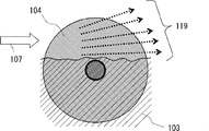
- FIG. 4 is an explanatory diagram relating to droplets generated from a rotating disk 104 in the oxygen molecular laser oscillator 100.
- FIG. 4 is an explanatory diagram relating to droplets generated from a rotating disk 104 in the oxygen molecular laser oscillator 100.
- FIG. 5 is an explanatory view showing a droplet 119B due to the centrifugal force of the rotating disk 104 in the oxygen molecular laser oscillator 100.
- 3 is a perspective view showing only a rotating disk 104 and a rotating shaft 105 in the oxygen molecular laser oscillator 100.
- FIG. 3 is a cross-sectional view of the oxygen molecular laser oscillator 100 as viewed from the side. 3 is a cross-sectional view showing a structure in which a refrigerant is taken in and out of a rotation shaft 105 in the oxygen molecular laser oscillator 100.
- FIG. 6 is a cross-sectional view showing a configuration of an oxygen molecular laser oscillator 200 according to Embodiment 2.
- FIG. FIG. 6 is a cross-sectional view showing a configuration of an oxygen molecular laser oscillator 300 according to Embodiment 3. It is a block diagram of COIL using a rotating disk type excited oxygen generator.
- FIG. Embodiment 1 of the present invention will be described below with reference to FIG.
- FIG. 1 is a cross-sectional view showing a configuration of an oxygen molecular laser oscillator 100 according to the present invention, and shows a structure in a cross section perpendicular to the optical axis OA1 of laser light to be oscillated.
- the oxygen molecular laser oscillator 100 includes a laser resonator 102 and an excitation oxygen generator 130.
- the oxygen molecular laser oscillator 100 has a structure in which a housing 101A for a laser resonator (that is, a space through which oscillating laser light passes) 102 and a housing 101B of an excitation oxygen generator 130 are combined.
- a thick pipe is used for both the housings 101A and 101B.
- the thick pipe is made of a metal having corrosion resistance against BHP solution and chlorine gas.
- a BHP solution 103 is stored in the housing 101B.
- a rotating disk 104 is rotatably disposed in the housing 101B. In the housing 101 ⁇ / b> B, the rotating disk 104 rotates around the rotating shaft 105.
- the rotating shaft 105 is parallel to the thickness direction of the rotating disk 104. In FIG. 1, the rotation shaft 105 is arranged along a direction perpendicular to the paper surface. The rotating shaft 105 is located at the center of the rotating disk 104.
- More than half of the rotating disk 104 is immersed in the BHP solution 103.
- nickel alloys such as Monel, Inconel, and Hastelloy are preferable because of their high corrosion resistance.
- transparent vinyl chloride is used as the material of the housings 101A and 101B.
- a tube may be used.
- the housing 101B has, for example, a cylindrical shape whose longitudinal direction is a direction perpendicular to the paper surface.
- the inner space of the housing 101B is wider than the outer diameter of the rotating disk 104.
- the housing 101B includes an injection pipe 108, a supply pipe 115, and a discharge pipe 117.
- An injection tube 108 is connected to the upper part of the housing 101B.
- a supply pipe 115 and a discharge pipe 117 are connected to the lower part of the housing 101B.
- the supply pipe 115 and the discharge pipe 117 are disposed below the injection pipe 108.
- the injection tube 108 is connected to the housing 101 ⁇ / b> B above the rotation shaft 105.
- supply pipe 115 and the discharge pipe 117 are connected to the housing 101 ⁇ / b> B below the rotation shaft 105.
- a plurality of injection pipes 108, supply pipes 115, and discharge pipes 117 may be arranged side by side in a direction perpendicular to the paper surface.
- a passage 121 is connected to the housing 101B.
- the passage 121 is connected to the housing 101B above the injection pipe.
- the passage 121 spatially connects the housing 101B and the housing 101A. That is, one end of the passage 121 is connected to the housing 101B, and the other end is connected to the housing 101A.
- the passage 121 is connected to the lower part of the housing 101A.
- the laser resonator is disposed immediately above the excitation oxygen generator and is directly connected to the excitation oxygen generator 130. That is, the laser oscillator is directly connected to the excitation oxygen generator 130 by the passage 121.
- the rotating disk 104 rotates in the direction of the arrow 106 around the rotating shaft 105. As a result, the upper surface not immersed in the BHP solution 103 is also covered with the BHP solution 103.
- the rotating disk 104 is also made of metal having corrosion resistance.
- the rotating shaft 105 is a metal pipe. Inside the rotating shaft 105, the refrigerant cooled to minus 20 degrees Celsius flows. Since both the rotating shaft 105 and the rotating disk 104 are made of metal, the thermal conductivity is high. Therefore, the rotating disk 104 is also maintained at about minus 20 degrees Celsius. Note that a nickel alloy having high corrosion resistance is preferable as the material of the rotating disk 104 and the rotating shaft 105.
- chlorine gas When generating excited oxygen molecules, chlorine gas is supplied from the direction of arrow 107. As a result, chlorine gas is injected from the injection pipe 108 into the housing 101B.
- the injection tube 108 is provided with a valve 109 that can be opened and closed. That is, there is a valve 109 in front of the housing 101B, and the valve 109 is opened only at the moment when excited oxygen molecules are generated.
- chlorine gas When chlorine gas is supplied into the housing 101 ⁇ / b> B, the chlorine gas and the BHP solution react on the surface of the rotating disk 104. This reaction generates O 2 ( 1 ⁇ g ).
- O 2 ( 1 ⁇ g ) generated in the housing 101B travels in the passage 121 as indicated by a dotted arrow 110. As a result, O 2 ( 1 ⁇ g ) flows into the laser resonator 102.
- FIG. 1 only one injection tube 108 is illustrated, but actually, a plurality of injection tubes 108 are arranged in a direction perpendicular to the paper surface.
- the rotating shaft 105 is a hollow pipe.
- the refrigerant flows through the hollow portion of the rotating shaft 105.
- the rotating shaft 105 and the rotating disk 104 can be kept at a low temperature.
- the rotating disk 104 is maintained at about minus 20 ° C.
- the BHP solution is also maintained at a low temperature that is substantially the same temperature.
- the viscosity of the BHP solution is about 30 mPa ⁇ s.
- the viscosity of the BHP solution at minus 20 ° C. is three times higher than the viscosity at 0 ° C. Therefore, even if chlorine gas flows on the surface of the rotating disk 104 at a high speed, the BHP solution covering the surface is not easily blown off.
- the BHP solution is also prevented from being blown off by the centrifugal force based on the rotation of the rotating disk 104.
- the viscosity of the BHP solution is shown in Non-Patent Document 8.
- the viscosity at 0 ° C. is 10 mPa ⁇ s, whereas at ⁇ 20 ° C., it is 30 mPa ⁇ s, which is three times higher.
- the viscosity of the BHP solution is high. Accordingly, the droplets to be blown off are not mist-like particles but relatively large droplets. Therefore, the droplet is not carried into the laser resonator 102 together with the excited oxygen molecules flowing as shown by the dotted line 110.
- a partition wall 111 that separates the housing 101A and the housing 101B is disposed below the laser resonator 102. For this reason, droplets of the BHP solution that fly linearly from the surface of the rotating disk 104 are blocked by the partition walls 111. As a result, the droplet can be prevented from crossing the laser resonator 102.
- the partition wall 111 is a part of the cylindrical housings 101 ⁇ / b> A and 101 ⁇ / b> B.
- the partition wall 111 is not particularly limited as long as it is a plate-like member disposed between the rotating disk 104 and the laser resonator 102. good.
- the right side of the partition wall 111 is a passage 121. It is necessary to provide a region for guiding excited oxygen molecules into the laser resonator 102 in a part of the housing 101B. Therefore, a part of the housing 101B is connected to the passage 121.
- the operation of the partition wall 111 will be supplementarily described with reference to FIG. 2, FIG. 3, and FIG.
- chlorine gas indicated by an arrow 107 is injected into the housing 101B at a high speed.
- the relatively large droplets 119 blown off from the surface of the rotating disk 104 fly linearly. Therefore, as shown in FIG. 3, the droplet 119 is stopped by the partition wall 111 or enters the passage 121.
- the droplet 119 entering the passage 121 collides with the inner wall 121 ⁇ / b> C on the right side of the passage 121. Accordingly, the droplet 119 does not enter the laser resonator 102 directly.
- the droplet 120 when the droplet 120 is generated by the centrifugal force based on the rotation of the rotating disk 104, the droplet 120 is blown in the tangential direction of the circumference of the rotating disk 104. 120 is blocked by a partition wall 111. Therefore, the droplet 120 does not jump directly into the laser resonator 102.
- the passage 121 is on the right side of the partition wall 111.
- the rotating disk 104 rotates in the direction in which the passage 121 is disposed with respect to the partition wall 111.
- the droplet 120 that jumps out of the rotating disk 104 by centrifugal force does not directly enter the laser resonator 102. That is, when considered in a cross section perpendicular to the rotation shaft 105, the partition wall 111 may be disposed on the upstream side in the rotation direction and the passage 121 may be disposed on the downstream side in the upper portion of the housing 101B.
- the passage 121 is disposed on the right side of the partition wall 111.
- the passage 121 has the partition wall 111. Located on the left side of
- the arrangement of the passage 121 and the partition wall 111 is determined according to the rotation direction of the rotating disk 104 in a plan view perpendicular to the rotating shaft 105.
- a partition wall 111 is disposed immediately above the rotation shaft 105.
- a passage 121 is disposed at a position shifted to the right from the rotation shaft 105.
- the valve 113 provided immediately above the laser resonator 102 is opened and exhausted in the direction of the arrow 114.
- the valve 113 is closed and the laser resonator 102 is filled with the generated excited oxygen molecules. That is, after the valve 113 is closed, the space in the housing 101A is filled with excited oxygen molecules.
- the valve 113 is disposed in the vicinity of the laser resonator 102. For this reason, the volume of the dead space before the valve 113 outside the laser resonator 102 is small. That is, the valve 113 is disposed in the exhaust pipe 112 at a position closer to the housing 101A.
- the exhaust pipe 112 is connected to a vacuum pump (not shown).
- the housing 101B that forms the excited oxygen generator 130 and the housing 101A that forms the laser resonator 102 are directly connected. For this reason, most of the space filled with excited oxygen molecules generated after the valve 113 is closed becomes the space in the laser resonator 102.
- the ratio is about 90%, and the dead space is very small. Therefore, it is easy to fill the excited oxygen molecules with a high pressure. For this reason, a high gain can be obtained and pulse oscillation can be easily realized.
- the BHP solution 103 stored in the lower part of the housing 101B is supplied from the supply pipe 115 as indicated by an arrow 116A.
- a cooled BHP solution may be supplied from the supply pipe 115.
- BHP solution 103 H 2 O is produced by a chemical reaction to produce O 2 (1 ⁇ g).
- O 2 (1 ⁇ g)
- the concentration of the BHP solution decreases.
- the H 2 O and BHP solutions are discharged from the discharge pipe 117 as indicated by an arrow 116B.
- the discharged BHP solution is supplied with the salt generated and adjusted in concentration, and then supplied again into the housing 101 from the supply pipe 115.
- FIG. 1 a perspective view of only the rotating disk 104 and the rotating shaft 105 is shown in FIG.
- a large number of rotating disks 104 are arranged in close contact with each other. That is, the plurality of rotating disks 104 are arranged side by side on the same axis.
- the plurality of rotating disks 104 have the same size. All of the rotating disk 104 is passed through and fixed to a pipe-shaped rotating shaft 105. That is, the rotating shaft 105 passes through the plurality of disks 104.
- a plurality of rotating disks 104 rotate around the rotating shaft 105.
- the refrigerant flows so as to enter from the arrow 118A and exit from the arrow 118B. Accordingly, the rotating shaft 105 and the rotating disk 104 in contact with the rotating shaft 105 can be kept at a low temperature at all times. In addition, by arranging a large number of rotating disks 104, the surface area in which a chemical reaction that generates excited oxygen molecules occurs is increased.
- FIG. 6 shows a cross-sectional structure of the oxygen molecular laser oscillator 100 according to this embodiment viewed from the side.
- the laser resonator 102 includes a total reflection mirror 131 and an output mirror 132 attached to both ends of the housing 101A.
- a total reflection mirror 131 is disposed at one end of the cylindrical housing 101A, and an output mirror 131 is disposed at the other end.
- the laser light is reflected by the total reflection mirror 131 and enters the output mirror 131. Part of the laser light incident on the output mirror 131 is extracted from the output mirror 131 to the outside of the laser resonator 102, and the rest is reflected in the direction of the total reflection mirror 131. Therefore, the laser beam is extracted like LA1.
- a cylindrical housing 101B and a cylindrical housing 101A are arranged in parallel. The optical axis of the laser light is substantially parallel to the rotation axis 105.
- the pipe-shaped rotating shaft 105 is attached to a motor 123 so that it can rotate.
- the rotating shaft 105 is held by fluid control boxes 124A and 124B for taking in and out the refrigerant flowing through the rotating shaft 105.
- the rotary shaft 105 is held while being sealed by two O-rings 126A and 126B. That is, since the fluid control box 124A holds the rotating shaft 105, the refrigerant flows as indicated by arrows. Then, the refrigerant is taken out from the inside of the rotating shaft 105 without leaking and circulates.
- O-rings are also provided on both side walls through which the rotating shaft 105 penetrates the housing 101 ⁇ / b> B.
- the tube 125 that connects the fluid control boxes 124A and 124B passes through the cooling device 127.
- the temperature of the refrigerant flowing inside the tube 125 is kept constant.
- the refrigerant does not freeze even at about minus 20 degrees Celsius and is not corrosive to metals.
- a fluorine-based fluid called Galden under the trade name is particularly preferable, but alcohol may also be used.
- FIG. 8 is a cross-sectional view of the oxygen molecular laser oscillator 200.
- the oxygen molecular laser oscillator 200 has a structure capable of obtaining a large mode volume like a laser resonator 202 including a housing 201A made of a thick wall pipe. Therefore, a laser output much higher than that of the oxygen molecular laser oscillator 100 shown in FIG. 1 can be obtained.
- the excited oxygen generator 230 includes a two-stage rotating disk 204A and a rotating disk 204B.
- the present embodiment is different from the first embodiment in that two stages of rotating disks 204A and 204B are provided. Note that the description of the configuration common to Embodiment 1 is omitted as appropriate.
- Rotating discs 204A and 204B are arranged in parallel.
- the rotating shaft 205A of the rotating disk 204A and the rotating shaft 205B of the rotating disk 204B are parallel to each other.
- the rotating disk 204A and the rotating disk 204B rotate in opposite directions as indicated by arrows in the drawing.
- the rotating disc 204A rotates in the left direction (counterclockwise)
- the rotating disc 204B rotates in the right direction (clockwise).
- the rotation shaft 205A is arranged so as to be offset from the rotation shaft 205B so that the rotation disc 204A and the rotation disc 204B do not interfere with each other.
- each rotating shaft 205A, 205B is hollow, and a refrigerant
- Chlorine gas for chemical reaction is supplied from the injection pipe 208 introduced from the lower part of the housing 201B. Chlorine gas proceeds from the bottom of the injection pipe 208 as indicated by an arrow 207 and is released from the left and right of the top end portion to the left and right as indicated by arrows.
- the injection tube 208 is disposed between the rotating disk 204A and the rotating disk 204B in a cross section perpendicular to the rotating shaft 205A. The injection tube 208 extends through the bottom of the housing 201B to the upper side of the liquid level of the BHP solution.
- supply pipes 215A and 215B are connected to the lower part of the housing 201B. That is, supply pipes 215A and 215B are introduced at the bottom of the housing 201B.
- the BHP solution flows through supply pipes 215A and 215B as indicated by arrows 216A and 216B.
- discharge pipes 217A and 217B are attached to the side surface of the housing 201B.
- the discharge pipe 217A and the discharge pipe 217B are connected to opposite side surfaces of the housing 201B.
- the discharge pipe 217A is connected to the left side surface of the housing 201B
- the discharge pipe 217B is connected to the right side surface of the housing 201B.
- the concentration of the BHP solution decreases due to a chemical reaction with chlorine gas.
- the BHP solution having a reduced concentration is discharged from the discharge pipes 217A and 217B as indicated by arrows 218A and 218B.
- a partition wall 211 which is a part of the housing 201A is disposed on the rotating disk 204A and the rotating disk 204B.
- the partition wall 211 is disposed on the rotating shaft 205A and the rotating shaft 205B.
- a passage 221B is disposed on the right side of the partition wall 211.
- a passage 221A is disposed on the left side of the partition wall 211. Therefore, the partition wall 211 is disposed between the passage 221A and the passage 221B.
- a block 222 is attached immediately above the rotating disc 204A and the rotating disc 204B in order to form a region through which chlorine gas flows.
- the block 222 is disposed immediately below the partition wall 211.
- the block 222 also has a function of reducing dead space. Therefore, the ratio of the volume of the laser resonator 202 in the entire space filled with the generated excited oxygen molecules is as high as about 90% as in the second embodiment. This facilitates pulse oscillation.
- the material of the block 222 is preferably a material that is corrosive and has high workability. Therefore, for example, a fluorine resin such as Teflon (registered trademark) or polypropylene is preferable as the material of the block 222.
- the number of disks can be increased. This increases the surface area in which a chemical reaction that generates excited oxygen molecules occurs. Therefore, the speed at which excited oxygen molecules are generated can be improved, and a high laser output can be obtained.
- FIG. 9 is a cross-sectional view of the oxygen molecular laser oscillator 300.
- the oxygen molecular laser oscillator 300 has a structure capable of obtaining a large mode volume like a laser resonator 302 including a housing 301A formed of a thick wall pipe.
- the rotating disks 304A and 304B that generate excited oxygen molecules have two stages.
- the excited oxygen generator 330 includes a two-stage rotating disk 304A and a rotating disk 304B.
- the present embodiment is different from the first embodiment in that two stages of rotating disks 304A and 304B are provided. Note that the description of the configuration common to Embodiment 1 is omitted as appropriate. Further, each of the rotating shafts 305A and 305B is hollow so that the refrigerant flows inside. Note that the description of the same configuration as that of Embodiment 1 will be omitted as appropriate.
- the rotating disks 304A and 304B are rotating in the opposite direction to the rotating direction of the rotating disks 204A and 204B shown in FIG.
- the rotary disc 304A and the rotary disc 304B are arranged side by side in a cross section perpendicular to the rotary shaft 305A. Then, the rotating disk 304A disposed on the left side rotates in the right direction (clockwise), and the rotating disk 304B disposed on the right side rotates in the left direction (counterclockwise).
- two sets of chlorine gas supply pipes 308A and 308B are also arranged outside the rotating disks 304A and 304B, respectively.
- a supply pipe 308A that supplies chlorine gas to the rotating disk 304A is connected to the left side surface of the housing 301B
- a supply pipe 308B that supplies chlorine gas to the rotating disk 304B is connected to the right side surface of the housing 301B.
- Chlorine gas is supplied as indicated by arrows 307A and 307B, respectively, and the valves 309A and 309B are opened to advance into the housing 301B. This initiates a chemical reaction that generates excited oxygen molecules.
- two sets of supply pipes 315A and 315B are arranged outside the rotating disks 304A and 304B.
- the supply pipe 315A is connected to the lower part of the left side surface of the housing 301B
- the supply pipe 315B is connected to the lower part of the right side surface of the housing 301B.
- the BHP solution is supplied from the supply pipes 315A and 315B to the inside of the housing 301B as indicated by arrows 316A and 316B.
- a discharge pipe 317 is connected to the bottom of the housing 301B. In the left-right direction, the discharge pipe 317 is disposed between the rotating disk 304A and the rotating disk 304B.
- the BHP solution having a reduced concentration due to the chemical reaction is discharged from the discharge pipe 317 as indicated by an arrow 318.
- blocks 322A and 322B for forming a region through which chlorine gas injected for causing a chemical reaction flows are provided in the housing 301B.
- Blocks 322A and 322B prevent chlorine gas from flowing directly into laser resonator 302 without contacting the BHP solution.
- the material of the blocks 322A and 322B is preferably Teflon (registered trademark), polypropylene, or the like, similar to the block 222.
- excited oxygen molecules generated in the two-stage rotating disks 304A and 304B are supplied into the laser resonator 302 from one passage 321.
- the passage 321 is disposed immediately below the optical axis OA3.
- a passage 321 is arranged on the right side of the partition wall 311A in the clockwise rotating (clockwise) rotating disc 304A.
- a passage 321 is disposed on the left side of the partition wall 311B in the counterclockwise rotating disc 304A.
- the processing of the housing 301A constituting the laser resonator 302 is simplified. That is, in order to form the passage 321, it is only necessary to provide one wide slit in the pipe made of the material of the housing 301 ⁇ / b> A.
- the partition walls 311A and 311B are the same as part of the housing 301A. However, the partition walls 311A and 311B are called partition walls because they are positioned immediately above the rotating disks 304A and 304B and block the droplets.
- the number of disks can be increased. This increases the surface area in which a chemical reaction that generates excited oxygen molecules occurs. Therefore, the speed at which excited oxygen molecules are generated can be improved, and a high laser output can be obtained.
- the rotating disk is rotated in order to generate excited oxygen, but other than the disk may be rotated. It is also possible to rotate a rotating plate having a shape other than a circular plate. That is, excited oxygen molecules can be generated by supplying chlorine gas to a rotating plate immersed in a BHP solution.
- this invention contains the appropriate deformation
- an oxygen molecular laser oscillator can be realized and pulse laser light can be generated.
- the apparatus can be easily enlarged, extremely large pulse energy can be easily generated by using a large chamber capable of storing a large amount of excited oxygen molecules. Therefore, it is suitable for laser fusion drivers that require extremely high energy pulse laser light, or for destroying dangerous flying objects.
Landscapes
- Physics & Mathematics (AREA)
- Electromagnetism (AREA)
- Engineering & Computer Science (AREA)
- Plasma & Fusion (AREA)
- Optics & Photonics (AREA)
- Lasers (AREA)
Abstract
Description
本発明は、励起状酸素分子から直接レーザ発振させることを目的としたレーザ発振器の構成に関する。 The present invention relates to a configuration of a laser oscillator intended to cause laser oscillation directly from excited oxygen molecules.
過酸化水素水(H2O2)と水酸化カリウム(KOH)または水酸化ナトリウム(NaOH)の混合溶液と、塩素ガスとの化学反応によって一重項の励起状酸素分子(通常、O2(1Δg)と示される。)を生成できることが知られており、O2(1Δg)のエネルギーをヨウ素原子(I)に移乗させる(すなわち基底状態のI(2P1/2)から励起状態のI(2P3/2)を生成する)ことでレーザ動作するヨウ素レーザ(一般にCOILと呼ばれている。COILは、Chemical Oxygen Iodine Laserの略である。)は、波長1.315ミクロンでレーザ発振する高出力レーザとして広く知られている。なお、ヨウ素レーザに関しては、下記、非特許文献1~4において説明されている。 Singlet excited oxygen molecules (usually O 2 ( 1 ) by a chemical reaction between a mixed solution of hydrogen peroxide (H 2 O 2 ) and potassium hydroxide (KOH) or sodium hydroxide (NaOH) and chlorine gas. Δ g ).), Which transfers the energy of O 2 ( 1 Δ g ) to the iodine atom (I) (ie excited from the ground state I ( 2 P 1/2 )) .COIL being called COIL iodine laser (generally to laser operation by the state of the I (2 P 3/2) to produce a) stands for Chemical oxygen iodine laser.) is a laser with a wavelength of 1.315 microns It is widely known as a high-power laser that oscillates. The iodine laser is described in Non-Patent Documents 1 to 4 below.
励起酸素分子を発生させる前記化学反応に関しては、例えば下記非特許文献5において概説されているように、スパージャーと呼ばれる方式が過去に多用されていた。スパージャー方式では、BHP溶液中にバブル状の塩素ガスを供給している。特にヨウ素レーザが発明された1977年から1990年代中頃までは、スパージャー方式が主流であった。 As for the chemical reaction that generates excited oxygen molecules, for example, as outlined in Non-Patent Document 5 below, a method called a sparger has been frequently used in the past. In the sparger method, bubble-like chlorine gas is supplied into the BHP solution. In particular, the sparger method was mainstream from 1977 when the iodine laser was invented to the mid-1990s.
一方、BHP溶液で濡らされた壁面に塩素ガスを接触させるウェッテドウォールと呼ばれる方式も1980年代に用いられることがあった。特に、ウェッテドウォール方式の一形態である回転円板方式は、BHP溶液を供給する流量を増すことが容易である。このため、回転円板方式は、1990年代後半まで広く利用されていた。 On the other hand, a method called a wetted wall in which chlorine gas is brought into contact with a wall wetted with a BHP solution was sometimes used in the 1980s. In particular, the rotating disk system, which is a form of the wetted wall system, can easily increase the flow rate for supplying the BHP solution. For this reason, the rotating disk method was widely used until the late 1990s.
その後はジェットと呼ばれる方式が利用され、ヨウ素レーザの高出力化に貢献している。ジェット方式ではBHP溶液をノズルからジェットとして噴出させ、これを塩素ガスとを反応させる方式である。つまりジェットとなったBHP溶液の総表面積が広いことから、瞬時に大量の化学反応を促進できる特徴がある。 After that, a method called jet is used, which contributes to higher output of iodine laser. In the jet method, the BHP solution is ejected as a jet from a nozzle, and this is reacted with chlorine gas. That is, since the total surface area of the BHP solution that has become a jet is large, there is a feature that a large amount of chemical reaction can be accelerated instantaneously.
しかしジェット方式ではジェット状のBHP溶液から水しぶき状のBHP溶液(以下、ドロップレットと呼ぶ。)が生じてしまう。ドロップレットがレーザ共振器まで運ばれて、レーザ発振に悪影響すると指摘されている。そこでエアロゾルと呼ばれる方式が開発されている。エアロゾル方式では、比較的大きなドロップレットの生成が抑制できるため、最も進化した手法の一つであると考えられている。 However, in the jet method, a spray-like BHP solution (hereinafter referred to as a droplet) is generated from the jet-like BHP solution. It has been pointed out that the droplets are carried to the laser resonator and adversely affect the laser oscillation. Therefore, a method called aerosol has been developed. The aerosol method is considered to be one of the most advanced methods because it can suppress the generation of relatively large droplets.
一方、ヨウ素レーザのように、励起したO2(1Δg)のエネルギーをヨウ素に移乗させてレーザ発振させる理由の一つとしては、O2(1Δg)を直接レーザ発振させることが困難だと考えられてきたからである。実際にO2(1Δg)を直接レーザ発振させたという報告は今までに皆無である。ただし、O2(1Δg)の直接レーザ発振を目指した実験が行われ、微弱な発光が検知されたとの報告があるが、レーザ発振を証明できるスペクトル観測は行われなかった。これに関しては、非特許文献6に示されている。非特許文献6によると、酸素分子レーザの発振が確認されているが、非常に微弱なエネルギーであり、それ以降、レーザ発振させたという報告は皆無であることから、実用化は極めて困難であると思われる。 On the other hand, it is difficult to directly oscillate O 2 ( 1 Δ g ) as one of the reasons for laser oscillation by transferring the excited O 2 ( 1 Δ g ) energy to iodine as in iodine lasers. This is because it has been considered. There has been no report that O 2 ( 1 Δ g ) was actually laser-oscillated. However, an experiment aimed at direct laser oscillation of O 2 ( 1 Δ g ) was conducted, and it was reported that weak light emission was detected, but no spectrum observation that could prove laser oscillation was performed. This is shown in Non-Patent Document 6. According to Non-Patent Document 6, the oscillation of an oxygen molecular laser has been confirmed, but since it is very weak energy and there has been no report of laser oscillation thereafter, practical application is extremely difficult. I think that the.
O2(1Δg)を直接レーザ発振させることが困難な理由として考えられることは、O2(1Δg)の自然放出寿命が極めて長いため、自然放出寿命に反比例する利得(ゲイン)が極めて低くなるからである。しかし、ゲインが小さくなることは、レーザ発振が不可能ということではなく、レーザ発振しにくいだけである。そこで、ゲイン長を極めて長くすればレーザ発振できると考えられる。なお、O2(1Δg)のレーザ発振を目指した実験も含めて理論考察された非特許文献7によると、レーザ発振の可能性が示されている。 O 2 (1 Δ g) be considered as difficult reasons be directly laser oscillation, since the spontaneous emission lifetime of O 2 (1 Δ g) is very long, the gain (gain) that is inversely proportional to the spontaneous emission lifetime This is because it becomes extremely low. However, reducing the gain does not mean that laser oscillation is impossible, but only that laser oscillation is difficult. Therefore, it is considered that laser oscillation can be achieved by making the gain length extremely long. Note that the possibility of laser oscillation is shown according to Non-Patent Document 7, which has been theoretically studied including an experiment aimed at laser oscillation of O 2 ( 1 Δ g ).
つまり大量のO2(1Δg)を瞬時に発生させることができれば、レーザ共振器内を、一瞬の間、高い圧力のO2(1Δg)で満たすことができる。このため、ゲインが高くなり、レーザ発振し易くなると考えられる。すなわちパルス動作であれば比較的容易にレーザ発振できると考えられる。なお、非特許文献6、及び非特許文献7は、パルス動作によるレーザ発振を目指した実験について報告している。 That is, if a large amount of O 2 ( 1 Δ g ) can be generated instantaneously, the laser resonator can be filled with high pressure O 2 ( 1 Δ g ) for a moment. For this reason, it is considered that the gain becomes high and laser oscillation is likely to occur. That is, it can be considered that laser oscillation can be relatively easily performed by a pulse operation. Non-Patent Document 6 and Non-Patent Document 7 report an experiment aimed at laser oscillation by pulse operation.
しかしながら、非特許文献7によると、O2(1Δg)の生成時にBHP溶液の微小なドロップレット(ミストと呼ぶ。)が発生する。このミストがレーザ光の散乱損失となって、レーザ発振を阻害すると指摘されている。特に、励起酸素発生器には多孔質パイプによるエアロゾル方式が用いられていた。このため、ミストの発生が避けられなかった。また、ミストを抑制するためにミストとO2(1Δg)とを分離するフィルタを用いることも考えられる。しかしながら、フィルタにより励起酸素分子が失活したり、酸素自体の透過率が低くなることが考えられる。このため、レーザ発振に十分な圧力のO2(1Δg)をレーザ共振器内に満たすことが困難になる。 However, according to Non-Patent Document 7, O 2 (referred to as mist.) (1 Δ g) fine droplets of the BHP solution when generating occurs. It has been pointed out that this mist becomes a scattering loss of laser light and hinders laser oscillation. In particular, an aerosol system using a porous pipe was used for the excited oxygen generator. For this reason, generation | occurrence | production of mist was inevitable. It is also conceivable to use a filter that separates mist and O 2 ( 1 Δ g ) in order to suppress mist. However, it is conceivable that excited oxygen molecules are deactivated by the filter, or the transmittance of oxygen itself is lowered. For this reason, it becomes difficult to fill the laser resonator with O 2 ( 1 Δ g ) having a pressure sufficient for laser oscillation.
本発明の目的は、以上に示した酸素分子レーザ発振器のレーザ発振を阻害する課題を解決し、パルス発振を容易に実現できる酸素分子レーザ発振器の構成を提供することである。 An object of the present invention is to solve the above-described problems that hinder laser oscillation of an oxygen molecular laser oscillator and to provide a configuration of an oxygen molecular laser oscillator that can easily realize pulse oscillation.
前記目的を達成するために、本発明の酸素分子レーザ発振器では、励起酸素発生器に回転円板式を用いて、かつ励起酸素発生器の直上にレーザ共振器を直結するように配置したものである。なお、回転円板式の励起酸素発生器に関しては、非特許文献5、非特許文献8、及び非特許文献9に示されている。 In order to achieve the above object, in the molecular oxygen laser oscillator of the present invention, a rotating disk type is used as an excitation oxygen generator, and a laser resonator is directly connected immediately above the excitation oxygen generator. . Non-patent document 5, Non-patent document 8, and Non-patent document 9 show rotating disk type excited oxygen generators.
回転円板式は、O2(1Δg)を発生させる化学反応は表面反応に基づくものである。一方、バブル方式やジェット方式はBHP溶液を吹き飛ばす手法である。非特許文献7で示されたようなエアロゾル方式は、BHP溶液のミストを発生させる方式である。回転円板式は、バブル方式やジェット方式やエアロゾル方式比べると、静かな表面反応によってO2(1Δg)を生成する。このため、回転円板式は、ドロップレットが極めて発生しにくい方式である。 In the rotating disk type, the chemical reaction that generates O 2 ( 1 Δ g ) is based on a surface reaction. On the other hand, the bubble method and the jet method are methods for blowing off the BHP solution. The aerosol system as shown in Non-Patent Document 7 is a system that generates mist of a BHP solution. The rotating disk type produces O 2 ( 1 Δ g ) by a quiet surface reaction compared to the bubble type, jet type, and aerosol type. For this reason, the rotating disk type is a system in which droplets are extremely unlikely to occur.
しかしながら、回転円板式励起酸素発生器を用いた従来のCOILをそのまま利用すると、以下の問題が生じる。従来の回転円板式励起酸素発生器は、例えば、図10に示した構造になっている。励起酸素発生器901には、BHP溶液が貯留されている。励起酸素発生器901には、回転軸905周りに回転する回転円板904が配置されている。BHP溶液906には、矢印907のように塩素ガスが供給される。したがって、励起酸素発生器901で、BHP溶液と塩素ガスが反応して、励起酸素分子が発生する。励起酸素分子は、矢印908のように、反応室902を流れていく。 However, if a conventional COIL using a rotating disk type excited oxygen generator is used as it is, the following problems occur. A conventional rotating disk type excited oxygen generator has a structure shown in FIG. 10, for example. The excited oxygen generator 901 stores a BHP solution. The excited oxygen generator 901 is provided with a rotating disk 904 that rotates around a rotating shaft 905. Chlorine gas is supplied to the BHP solution 906 as indicated by an arrow 907. Therefore, the excited oxygen generator 901 reacts with the BHP solution and the chlorine gas to generate excited oxygen molecules. Excited oxygen molecules flow through the reaction chamber 902 as indicated by an arrow 908.
反応室902には、ヨウ素原子の注入部909が設けられている。したがって、反応室902には、ヨウ素原子と励起酸素分子の混合流が矢印910のように流れていく。よって、励起酸素分子が反応室902でヨウ素原子と反応して、励起ヨウ素原子が発生する。励起ヨウ素原子は、反応部902を経由して、レーザ共振器903内に到達する。これにより、レーザ共振器903が励起ヨウ素原子で満たされる。反応室902は、レーザ共振器903を介して、矢印912のように排気される。 In the reaction chamber 902, an iodine atom injection portion 909 is provided. Therefore, a mixed flow of iodine atoms and excited oxygen molecules flows in the reaction chamber 902 as indicated by an arrow 910. Thus, excited oxygen molecules react with iodine atoms in the reaction chamber 902 to generate excited iodine atoms. Excited iodine atoms reach the laser resonator 903 via the reaction unit 902. This fills the laser resonator 903 with excited iodine atoms. The reaction chamber 902 is exhausted as indicated by an arrow 912 through the laser resonator 903.
高速で流れる励起酸素分子とヨウ素原子とを十分混合させるために、反応部902はある程度の長さが必要になっている。その結果、レーザ共振器903の体積は、励起酸素発生器901から発生した励起酸素分子が満たされる全領域の体積に比べて10~30%と小さくなってしまう。なお、レーザ光の光軸OA9は紙面に垂直方向である。 In order to sufficiently mix excited oxygen molecules and iodine atoms flowing at high speed, the reaction section 902 needs to have a certain length. As a result, the volume of the laser resonator 903 becomes as small as 10 to 30% as compared with the volume of the entire region where the excited oxygen molecules generated from the excited oxygen generator 901 are filled. The optical axis OA9 of the laser beam is perpendicular to the paper surface.
そこで本発明では、励起酸素発生器とレーザ共振器とを直結している。これによると、レーザ共振器内の体積は、励起酸素発生器から発生した励起酸素分子が満たされる全領域の体積の80%以上の高い割合にすることができる。従って、励起酸素発生器から同じ質量の励起酸素分子を発生させても、従来のCOILを利用する場合に比べて、3~9倍も高い圧力でO2(1Δg)を蓄積できる。その結果、高いゲインが得られるため、レーザ発振し易くなる。 Therefore, in the present invention, the excited oxygen generator and the laser resonator are directly connected. According to this, the volume in the laser resonator can be a high ratio of 80% or more of the volume of the entire region filled with the excited oxygen molecules generated from the excited oxygen generator. Therefore, even if excited oxygen molecules having the same mass are generated from the excited oxygen generator, O 2 ( 1 Δ g ) can be accumulated at a pressure 3 to 9 times higher than in the case of using the conventional COIL. As a result, a high gain can be obtained, which facilitates laser oscillation.
さらにまた、酸素分子レーザ発振器を動作させる場合、高いゲインを得るために、瞬時に高圧のO2(1Δg)を発生する必要がある。すなわち大量の塩素ガスを一気に注入して化学反応させる必要がある。その結果、たとえ表面反応であっても、高速に流れる塩素ガスによってBHP溶液が表面から比較的大きなドロップレットとなって吹き飛ばされるおそれがある。よって、ドロップレットがレーザ共振器内に入り込んでレーザ発振を阻止することが懸念される。そこで本発明では、励起酸素発生器とレーザ共振器との間に隔壁を設けている。 Furthermore, when operating the molecular oxygen laser oscillator, it is necessary to instantaneously generate high-pressure O 2 ( 1 Δ g ) in order to obtain a high gain. That is, it is necessary to inject a large amount of chlorine gas at a time to cause a chemical reaction. As a result, even if it is a surface reaction, the BHP solution may be blown off as relatively large droplets from the surface by chlorine gas flowing at high speed. Therefore, there is a concern that the droplets enter the laser resonator and prevent laser oscillation. Therefore, in the present invention, a partition wall is provided between the excited oxygen generator and the laser resonator.
また、ドロップレットの発生をさらに抑制するために、回転円板の回転軸をパイプで構成してもよい。そして、回転軸内に冷媒を流せる構造を用いるようにしてもよい。これによると、回転円板を低温に保つことができる。このため、回転円板の表面を覆ったBHP溶液も同程度の低温にできる。その結果、BHP溶液の粘度を高くでき、BHP溶液の表面張力が高くなる。これにより、高速で流れる塩素ガスに接しても、BHP溶液が表面から吹き飛ばされにくくなる。さらに、回転円板と回転軸には耐食性を有する金属を材料とすることが好ましい。 Also, in order to further suppress the generation of droplets, the rotating shaft of the rotating disk may be constituted by a pipe. And you may make it use the structure which can flow a refrigerant | coolant in a rotating shaft. According to this, the rotating disk can be kept at a low temperature. For this reason, the BHP solution covering the surface of the rotating disk can also be made at a similar low temperature. As a result, the viscosity of the BHP solution can be increased and the surface tension of the BHP solution is increased. This makes it difficult for the BHP solution to be blown off from the surface even in contact with chlorine gas flowing at high speed. Furthermore, it is preferable to use a metal having corrosion resistance for the rotating disk and the rotating shaft.
BHP溶液の温度が低い方がドロップレットを生じさせにくいことになる。本発明では、装置外部で冷却したBHP溶液を励起酸素発生器に供給するのではなく、回転円板の回転軸内に冷媒を流している。励起酸素を発生させる化学反応を起こすと、反応熱によってBHP溶液が加熱される。このことから、外部で冷やしたBHP溶液を供給しても、反応によって直ぐに温度上昇してしまう。これに対して本発明では、回転円板自体が常時冷却されるため、励起酸素分子を発生させ続けても、BHP溶液を常時低温に保つことが可能である。 The lower the temperature of the BHP solution, the harder it is to generate droplets. In the present invention, the BHP solution cooled outside the apparatus is not supplied to the excited oxygen generator, but the refrigerant is caused to flow in the rotating shaft of the rotating disk. When a chemical reaction that generates excited oxygen occurs, the BHP solution is heated by heat of reaction. For this reason, even if an externally cooled BHP solution is supplied, the temperature immediately rises due to the reaction. In contrast, in the present invention, since the rotating disk itself is constantly cooled, it is possible to always keep the BHP solution at a low temperature even if excited oxygen molecules are continuously generated.
さらにまた、本発明では回転軸に冷媒を流すことで回転円板を冷却させるようにしている。このため、回転速度が遅い場合でも回転円板に接触しているBHP溶液を十分冷却できる効果がある。回転速度を低くすることができる。回転速度を低くすると、回転の遠心力によって生じるドロップレットも抑制できる。これに対して、BHP溶液を溜めた容器の外部から冷却する構造とした場合、回転円板の表面に付いたBHP溶液を低温に保つには、回転円板をある程度速く回転させる必要が生じてしまう。この結果ドロップレットが生じやすくなる。 Furthermore, in the present invention, the rotating disk is cooled by flowing a coolant through the rotating shaft. For this reason, even when a rotational speed is slow, there exists an effect which can fully cool the BHP solution which is contacting the rotation disc. The rotation speed can be lowered. If the rotation speed is lowered, droplets generated by the centrifugal force of rotation can be suppressed. In contrast, in the case of cooling from the outside of the container in which the BHP solution is stored, in order to keep the BHP solution attached to the surface of the rotating disk at a low temperature, it is necessary to rotate the rotating disk to some extent. End up. As a result, droplets are likely to occur.
本発明によれば、パルス発振を容易に実現できる酸素分子レーザ発振器の構成を提供することができる。 According to the present invention, it is possible to provide a configuration of an oxygen molecular laser oscillator that can easily realize pulse oscillation.
添付の図面を参照して本発明の実施形態を説明する。以下に説明する実施形態は本発明の実施例であり、本発明は、以下の実施形態に制限されるものではない。なお、本明細書及び図面において符号が同じ構成要素は、相互に同一のものを示すものとする。 Embodiments of the present invention will be described with reference to the accompanying drawings. The embodiments described below are examples of the present invention, and the present invention is not limited to the following embodiments. In the present specification and drawings, the same reference numerals denote the same components.
実施の形態1.
以下、本発明の実施の形態1を図1に基づいて説明する。図1は本発明の酸素分子レーザ発振器100の構成を示す断面図であり、発振させるレーザ光の光軸OA1に垂直な断面内の構造を示したものである。酸素分子レーザ発振器100は、レーザ共振器102と励起酸素発生器130を備えている。酸素分子レーザ発振器100は、レーザ共振器(つまり発振するレーザ光が通過する空間)102用のハウジング101Aと励起酸素発生器130のハウジング101Bとが合体した構造になっている。ハウジング101A,101Bのいずれにも、肉厚パイプが利用されている。肉厚パイプは、BHP溶液や塩素ガスに対して耐食性を有する金属製である。
Embodiment 1 FIG.
Embodiment 1 of the present invention will be described below with reference to FIG. FIG. 1 is a cross-sectional view showing a configuration of an oxygen
ハウジング101Bには、BHP溶液103が溜められている。また、ハウジング101B内には、回転円板104が回転可能に配置されている。ハウジング101B内において、回転円板104は、回転軸105周りに回転する。なお、回転軸105は、回転円板104の厚さ方向と平行になっている。図1において、回転軸105は、紙面と垂直な方向に沿って配置されている。また、回転軸105は、回転円板104の中心に位置している。
A
回転円板104の半分以上がBHP溶液103内に浸っている。なお、ハウジング101A、101Bの材質としては、モネル、インコネル、ハステロイなどのニッケル合金が耐食性の高いため好ましい、さらに、内部を観察できるようにするために、ハウジング101A、101Bの材質として、透明の塩ビ管を用いても良い。
More than half of the
ハウジング101Bは、例えば、紙面と垂直な方向を長手方向とする円筒状になっている。そして、ハウジング101Bの内部空間は、回転円板104の外径よりも広くなっている。ハウジング101Bは、注入管108、供給管115、及び排出管117を備えている。ハウジング101Bの上部には、注入管108が接続されている。ハウジング101Bの下部には、供給管115、及び排出管117が接続されている。供給管115、及び排出管117は、注入管108よりも下側に配置されている。例えば、注入管108は、回転軸105よりも上側において、ハウジング101Bに接続されている。また、供給管115、及び排出管117は、回転軸105よりも下側において、ハウジング101Bに接続されている。注入管108、供給管115、排出管117は、紙面と垂直な方向に複数並んで配置されていてもよい。
The
さらに、ハウジング101Bには通路121が接続されている。通路121は、注入管108よりも上側で、ハウジング101Bと接続している。通路121は、ハウジング101Bとハウジング101Aとを空間的に繋げている。すなわち、通路121の一端がハウジング101Bと接続し、他端がハウジング101Aと接続している。通路121は、ハウジング101Aの下部に接続されている。レーザ共振器は、励起酸素発生器の真上に配置され、励起酸素発生器130に直結されている。すなわち、レーザ発振器は、通路121によって励起酸素発生器130と直結されている。
Furthermore, a
回転円板104は回転軸105を中心に矢印106の方向に回転している。その結果、BHP溶液103に浸っていない上部の表面もBHP溶液103で覆われるようになる。回転円板104も耐食性を有する金属製である。回転軸105は金属製のパイプになっている。回転軸105の内部には、摂氏マイナス20度に冷やされた冷媒が流れている。回転軸105も回転円板104も金属製であるため、熱伝導率が高い。したがって、回転円板104も摂氏約マイナス20度に保たれる。なお、回転円板104と回転軸105の材質としても耐食性の高いニッケル合金が好ましい。
The
励起酸素分子を発生させる際は、塩素ガスを矢印107の方向から供給する。これにより、塩素ガスが、注入管108内からハウジング101B内に注入される。注入管108には開閉可能なバルブ109が設けられている。すなわち、ハウジング101Bの手前にバルブ109があり、励起酸素分子を発生させる瞬間だけバルブ109が開く。塩素ガスがハウジング101B内に供給されると、塩素ガスとBHP溶液とが回転円板104の表面で反応する。この反応によってO2(1Δg)が発生する。
When generating excited oxygen molecules, chlorine gas is supplied from the direction of
ハウジング101B内で発生したO2(1Δg)は、通路121内を点線矢印110のように進んでいく。これにより、O2(1Δg)がレーザ共振器102内まで流されていく。なお、図1では注入管108は1本しか描かれていないが、実際は紙面に垂直な方向に複数並べられている。
O 2 ( 1 Δ g ) generated in the
回転軸105は中空のパイプとなっている。そして、回転軸105の中空部分を冷媒が流れている。こうすることで、回転軸105、及び回転円板104を低温に保つことができる。回転円板104が約マイナス20℃に保たれることで、BHP溶液もほぼ同温の低い温度に保たれる。その結果、BHP溶液の粘度は約30mPa・sとなる。マイナス20℃でのBHP溶液の粘度は、0℃での粘度に比べると3倍も高い。そのため、回転円板104の表面を塩素ガスが高速で流れても、表面を覆っているBHP溶液は吹き飛ばされにくくなる。さらには、回転円板104の回転に基づく遠心力によってBHP溶液が吹き飛ばされることも抑制される。なお、BHP溶液の粘度に関しては、非特許文献8に示されている。0℃における粘度は10mPa・sであるのに対して、-20℃では30mPa・sと3倍も高い。
The
一方、もしも回転円板104の表面を覆っているBHP溶液が高速の塩素ガスによって吹き飛ばされることがあっても、BHP溶液の粘度が高くなっている。したがって、吹き飛ばされるドロップレットは、粒子の小さなミスト状ではなく、比較的大きなドロップレットになる。よって、ドロップレットが点線110で示されたように流れる励起酸素分子と一緒になってレーザ共振器102内に運ばれることはない。
On the other hand, even if the BHP solution covering the surface of the
しかもレーザ共振器102の下部には、ハウジング101Aとハウジング101Bとを隔てる隔壁111が配置されている。このため、回転円板104の表面から直線的に飛んで来るBHP溶液のドロップレットが、隔壁111で遮断される。これにより、ドロップレットが、レーザ共振器102内を横切ることを防ぐことができる。なお、隔壁111は、本実施形態では、円筒状であるハウジング101A、及び101Bの一部であるが、回転円板104とレーザ共振器102との間に配置される板状のものであれば良い。ただし、この隔壁111の右側は通路121になっている。ハウジング101Bの一部に、励起酸素分子をレーザ共振器102内に導く領域を設ける必要がある。したがって、ハウジング101Bの一部が、通路121と接続されている。
Moreover, a
ここで、隔壁111の作用に関して、図2、図3、及び図4を用いて補足説明する。図2に示したように、矢印107で示された塩素ガスがハウジング101B内に高速に注入される。すると、回転円板104の表面から吹き飛ばされる比較的大きなドロップレット119は直線的に飛行する。このため、図3に示したように、ドロップレット119は、隔壁111で止められるか、あるいは通路121に侵入する。しかし通路121に侵入するドロップレット119は、通路121の右側の内壁121Cに衝突する。従って、レーザ共振器102の内部にドロップレット119が直接入り込むことはない。
Here, the operation of the
さらにまた、図4に示したように、回転円板104の回転に基づく遠心力によってドロップレット120が生じる場合は、回転円板104の円周の接線方向に飛ばされる、このことから、ドロップレット120は、隔壁111でブロックされる。よって、ドロップレット120は、レーザ共振器102内に直接飛び込んでくることはない。
Furthermore, as shown in FIG. 4, when the
なお、回転円板104の回転方向は矢印106で示したように右回転(時計回りに回転)しているため、通路121は隔壁111の右側になっている。このように、隔壁111に対して通路121が配置される方向に、回転円板104が回転するようになっている。このため、回転円板104から遠心力によって飛び出すドロップレット120が、レーザ共振器102内に直接入り込むことはない。すなわち、回転軸105と垂直な断面で考えた場合、ハウジング101Bの上部において、回転方向の上流側に隔壁111が配置され、下流側に通路121が配置されていればよい。
In addition, since the rotation direction of the
例えば、回転円板104が右回転(時計回りの回転)となるように回転軸105の方向に沿って励起酸素発生器130を見た場合、通路121が隔壁111の右側に配置される。また、反対方向に見た場合、すなわち、回転円板104が左回転(反時計回り)となるように回転軸105の方向に沿って励起酸素発生器130を見た場合、通路121は隔壁111の左側に位置する。このように、回転軸105と垂直な平面視において、回転円板104の回転方向に応じて、通路121と隔壁111の配置が決まる。図1では、回転軸105の真上には、隔壁111が配置される。回転軸105から右方向にずれた位置に、通路121が配置されている。
For example, when the
ところで、レーザ動作させる直前は、図1に示されているように、レーザ共振器102内を排気管112から真空排気しておく必要がある。そのため、レーザ共振器102の直上に設けられたバルブ113を開いて、矢印114の方向に排気しておく。ただし真空排気後は、バルブ113が閉じられ、発生される励起酸素分子でレーザ共振器102内が満たされる。すなわち、バルブ113を閉じた後、ハウジング101A内の空間が、励起酸素分子で満たされる。ここで、バルブ113がレーザ共振器102の近傍に配置されている。このため、レーザ共振器102の外部でバルブ113の手前であるデッドスペースの体積は小さくなっている。すなわち、排気管112において、ハウジング101Aにより近い位置に、バルブ113を配置している。もちろん、排気管112は、図示しない真空ポンプに接続されている。
Incidentally, it is necessary to evacuate the
以上に説明したように、酸素分子レーザ発振器100では、励起酸素発生器130を形成するハウジング101Bとレーザ共振器102を形成するハウジング101Aとが直結している。このため、バルブ113が閉じられてから発生させられる励起酸素分子が満たされる空間のほとんどがレーザ共振器102内の空間になる。その割合は約90%であり、デッドスペースが非常に少ない構造になっている。従って、励起酸素分子を高い圧力で満たすことが容易になっている。このため、高いゲインが得られ、パルス発振が容易に実現できる。
As described above, in the oxygen
ところで、ハウジング101Bの下部に溜められたBHP溶液103は、供給管115から矢印116Aのように供給される。なお、供給管115から冷却したBHP溶液を供給してもよい。一方、BHP溶液103はO2(1Δg)を生成させる化学反応によってH2Oが生成する。H2Oが生成すると、BHP溶液の濃度が低下していく。よって、H2O及びBHP溶液は、排出管117から矢印116Bのように排出される。排出されるBHP溶液は生成する塩が除去され、濃度が調整された後、再び供給管115からハウジング101内に供給される。
By the way, the
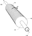
次に回転円板104、及び回転軸105のみの斜視図を図5に示す。図示されたように回転円板104は多数が密接するように並べられている。すなわち、複数の回転円板104が同軸となって並設されている。複数の回転円板104は同じ大きさとなっている。回転円板104の全てがパイプ状の回転軸105に通されて固定されている。すなわち、回転軸105が複数の円板104を貫通している。複数の回転円板104が回転軸105に周りに回転する。
Next, a perspective view of only the
回転軸105の中には、冷媒が矢印118Aから入り、矢印118Bから出るように流れている。これによって回転軸105、及びこれと接触している回転円板104を常時低温に保つことができる。また、回転円板104を多数並べることで、励起酸素分子を発生させる化学反応が生じる表面積が大きくなる。
In the
また、本実施形態の酸素分子レーザ発振器100を横から見た断面構造を図6に示す。レーザ共振器102は、ハウジング101Aの両端に取り付けられた全反射鏡131と出力鏡132とで構成されている。円筒状のハウジング101Aの一端には、全反射鏡131が配置され、他端には、出力鏡131が配置されている。レーザ光は、全反射鏡131で反射して、出力鏡131に入射する。出力鏡131に入射したレーザ光の一部は、出力鏡131からレーザ共振器102の外部に取り出され、残りは、全反射鏡131の方向に反射する。したがって、レーザ光はLA1のように取り出される。また、円筒状のハウジング101Bと円筒状のハウジング101Aとが平行に配置されている。レーザ光の光軸は、回転軸105とほぼ平行になっている。
Further, FIG. 6 shows a cross-sectional structure of the oxygen
一方、パイプ状の回転軸105は、モーター123に取り付けられており、回転できるようになっている。ただし回転軸105は、その内部を流す冷媒を出し入れする流体制御ボックス124A、及び124Bで保持されている。その詳細構造としては、図7に示した断面図のように、例えば流体制御ボックス124Aでは、2枚のOリング126A、126Bによって回転軸105がシールされながら、保持される。つまり、流体制御ボックス124Aは、回転軸105を保持しているため、冷媒は矢印で示したように流れる。そして、冷媒が回転軸105の内部からリークすることなく取り出され、巡回するようになっている。なお、図6には示されていないが、回転軸105がハウジング101Bを突き抜ける両側の壁にもOリングが備えられている。
On the other hand, the pipe-shaped
また、流体制御ボックス124Aと124Bとを繋ぐチューブ125は、冷却装置127を経由している。これによって、チューブ125の内部を流れる冷媒の温度は一定に保たれる。なお、冷媒に関しては、摂氏マイナス20度程度でも凍結せず、かつ金属に対して腐食性の無いものが好ましい。冷媒として商品名でガルデンと呼ばれるフッ素系流体が特に好ましいが、アルコールでも良い。
Further, the
実施の形態2.
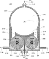
次に、実施形態2にかかる酸素分子レーザ発振器について、図8を用いて説明する。図8は酸素分子レーザ発振器200の断面図である。酸素分子レーザ発振器200は、太い肉厚パイプから成るハウジング201Aで構成されるレーザ共振器202のように、大きなモードボリュームが得られる構造になっている。よって、図1に示した酸素分子レーザ発振器100に比べて遥かに高いレーザ出力を得ることができる。
Embodiment 2. FIG.
Next, an oxygen molecular laser oscillator according to Embodiment 2 will be described with reference to FIG. FIG. 8 is a cross-sectional view of the oxygen
高いレーザ出力を実現するために、励起酸素発生器230は、2段の回転円板204A、及び回転円板204Bを備えている。本実施の形態では、2段の回転円板204A、204Bが設けられている点において、実施の形態1と異なっている。なお、実施の形態1と共通の構成については、適宜説明を省略する。
In order to realize a high laser output, the
回転円板204A、及び204Bは並行に並べられている。回転円板204Aの回転軸205Aと、回転円板204Bの回転軸205Bは平行になっている。そして、回転円板204A、及び回転円板204Bは、図中に矢印で示されたように互いに反対方向に回転するようになっている。図8では、回転円板204Aは、左方向(反時計回り)に回転し、回転円板204Bは、右方向(時計回り)に回転する。回転軸205Aと垂直な断面において、回転円板204Aと回転円板204Bが干渉しないように、回転軸205Aは回転軸205Bからずれて配置されている。
Rotating
図8では単に2枚の円板が描かれてあるが、実際には回転円板204A、及び回転円板204Bは、紙面に垂直な方向に多数が並べられている。この点については、図5等に示した構成と同様であるため、詳細な説明を省略する。また、それぞれの回転軸205A、205Bは中空になっており、内部を冷媒が流れるようになっている。この点については、図6、図7等で示した構成と同様であるため、説明を省略する。
In FIG. 8, only two disks are drawn, but in reality, a large number of
化学反応させるための塩素ガスは、ハウジング201Bの下部から導入された注入管208から供給される。塩素ガスは、矢印207のように注入管208内を下から進んできて、上部の先端部の左右から矢印で示したように左右に放出される。回転軸205Aと垂直な断面において、注入管208は、回転円板204Aと回転円板204Bの間に配置されている。注入管208は、ハウジング201Bの底部を通ってBHP溶液の液面よりも上側まで延在している。
Chlorine gas for chemical reaction is supplied from the
また、ハウジング201Bの下部には、供給管215A、215Bが接続されている。すなわち、ハウジング201Bの底部には、供給管215A,215Bが導入されている。BHP溶液は、供給管215A、215Bを通り、矢印216A、216Bのように流入するようになっている。また、ハウジング201Bの側面には、排出管217A、217Bが取り付けられている。排出管217Aと排出管217Bは、ハウジング201Bの対向する側面に接続されている。ここでは、排出管217Aがハウジング201Bの左側面に接続され、排出管217Bがハウジング201Bの右側面に接続されている。上記のように、BHP溶液は、塩素ガスとの化学反応によって濃度が低下する。濃度が低下したBHP溶液は、排出管217A、217Bから矢印218A、218Bのように排出される。
Further,
回転円板204Aと回転円板204Bの上には、ハウジング201Aの一部分である隔壁211が配置している。これによって回転円板204A、204Bの表面に付着したBHP溶液が塩素ガスによって飛ばされてドロップレットが発生しても、これが直接レーザ共振器202内に流れ込んでくることはない。
A
隔壁211は、回転軸205A、及び回転軸205Bの上に配置されている。右回転(時計回り)の回転円板204Bにおいては、隔壁211の右側に通路221Bが配置されている。左回転(反時計回り)の回転円板204Aにおいては、隔壁211の左側に通路221Aが配置されている。したがって、通路221Aと通路221Bとの間に、隔壁211が配置されている。
The
また、回転円板204Aと回転円板204Bの直上には塩素ガスの流れる領域を形成するためにブロック222が取り付けられている。ブロック222は、隔壁211の直下に配置されている。ブロック222を設けることで、塩素ガスは回転円板204A、204Bの表面付近のみを流れるようになる。塩素ガスがBHP溶液に接触せずにレーザ共振器202内に直接流入するのが抑制される。また、ブロック222はデッドスペースを低減する機能も有している。したがって、発生する励起酸素分子が満たされる全空間に占めるレーザ共振器202の体積の割合は、実施形態2と同様に、90%程度と高くなっている。これによってパルス発振し易くなっている。なお、ブロック222の材質としては、腐食性を有し、しかも加工性も高い材料が好ましい。したがって、例えば、テフロン(登録商標)やポリプロピレンなどのフッ素系樹脂が、ブロック222の材質として好ましい。
Also, a
本実施の形態では、2段の回転円板204A,回転円板204Bを用いているため、円板の数を増やすことができる。これにより、励起酸素分子を発生させる化学反応が生じる表面積が大きくなる。よって、励起酸素分子を発生させる速度を向上することができ、高いレーザ出力を得ることができる。
In this embodiment, since the two-stage
実施の形態3.
次に、実施形態3にかかる酸素分子レーザ発振器300について、図9を用いて説明する。図9は酸素分子レーザ発振器300の断面図である。酸素分子レーザ発振器300は、太い肉厚パイプから成るハウジング301Aで構成されるレーザ共振器302のように、大きなモードボリュームが得られる構造になっている。本実施の形態では、励起酸素分子を発生させる回転円板304A、304Bは2段になっている。
Embodiment 3 FIG.
Next, an oxygen
高いレーザ出力を実現するために、励起酸素発生器330は、2段の回転円板304A、及び回転円板304Bを備えている。本実施の形態では、2段の回転円板304A、304Bが設けられている点において、実施の形態1と異なっている。なお、実施の形態1と共通の構成については、適宜説明を省略する。さらに、それぞれの回転軸305A、305Bは中空となっており、内部を冷媒が流れるようになっている。なお、実施の形態1と同様の構成については適宜説明を省略する。
In order to realize a high laser output, the
本実施例における回転円板304A、304Bは、図8に示された回転円板204A、204Bの回転方向と、どちらも反対側に回転している。例えば、回転軸305Aと垂直な断面において、回転円板304Aと回転円板304Bは左右に並んで配置されている。そして、左側に配置された回転円板304Aは、右方向(時計回り)に回転し、右側に配置された回転円板304Bは、左方向(反時計回り)に回転する。
In the present embodiment, the
そのため塩素ガスの供給管308A、308Bも2組、それぞれ回転円板304A、304Bの外側に配置されている。例えば、回転円板304Aに塩素ガスを供給する供給管308Aは、ハウジング301Bの左側面に接続され、回転円板304Bに塩素ガスを供給する供給管308Bは、ハウジング301Bの右側面に接続されている。塩素ガスはそれぞれ矢印307A、307Bのように供給され、バルブ309A、309Bを開くことで、ハウジング301Bの内部に進む。これにより、励起酸素分子を発生させる化学反応が開始する。
Therefore, two sets of chlorine
一方、BHP溶液の供給についても、回転円板304A、304Bの外側に2組の供給管315A、315Bが配置されている。供給管315Aは、ハウジング301Bの左側面下部に接続され、供給管315Bは、ハウジング301Bの右側面下部に接続されている。BHP溶液は供給管315A,315Bから矢印316A、316Bのようにハウジング301Bの内部にそれぞれ供給される。ハウジング301Bの底部には、排出管317が接続されている。左右方向において、排出管317は、回転円板304Aと回転円板304Bとの間に配置されている。化学反応によって濃度が低下したBHP溶液は、排出管317から矢印318のように排出される。
On the other hand, also for the supply of the BHP solution, two sets of
本実施例では、化学反応させるために注入される塩素ガスが流れる領域を形成するためのブロック322A、322Bがハウジング301B内に設けられている。ブロック322A,322Bにより塩素ガスがBHP溶液と接触せずにレーザ共振器302内に直接流れ込むのを抑制している。これらブロック322A、322Bの材質も、ブロック222と同様に、テフロン(登録商標)やポリプロピレン等が好ましい。
In this embodiment, blocks 322A and 322B for forming a region through which chlorine gas injected for causing a chemical reaction flows are provided in the
本実施形態の特徴としては、2段の回転円板304A、304Bにおいて発生する励起酸素分子を1か所の通路321からレーザ共振器302内に供給するようになっている。通路321は、光軸OA3の直下に配置される。右回転(時計回り)の回転円板304Aにおいて、隔壁311Aの右側に通路321が配置されている。左回転(反時計回り)の回転円板304Aにおいて、隔壁311Bの左側に通路321が配置されている。
As a feature of this embodiment, excited oxygen molecules generated in the two-
そのため、レーザ共振器302を構成するハウジング301Aの加工が簡単になる。つまり通路321を形成するには、ハウジング301Aの材料のパイプに幅の広いスリットを1か所設けるだけで良い。
Therefore, the processing of the
また、もしも回転円板304Aの表面に付着したBHP溶液が塩素ガスによって吹き飛ばされる場合は、発生するドロップレット320は点線矢印のように飛ばされ、隔壁311Bの端部に当たるだけである。よって、ドロップレット320がレーザ共振器302内に直接入り込む量は極めて少ない。なお隔壁311A、311Bとはハウジング301Aの一部と同一であるが、それぞれ回転円板304A、304Bの直上に位置して、ドロップレットをブロックするため、隔壁と呼んでいる。
Also, if the BHP solution adhering to the surface of the
本実施の形態では、2段の回転円板204A,回転円板204Bを用いているため、円板の数を増やすことができる。これにより、励起酸素分子を発生させる化学反応が生じる表面積が大きくなる。よって、励起酸素分子を発生させる速度を向上することができ、高いレーザ出力を得ることができる。
In this embodiment, since the two-stage
なお、実施の形態1~3では、励起酸素を発生させるために、回転円板を回転させたが、円板以外を回転させるようしてもよい。円板以外の形状を有する回転板を回転させるようにすることも可能である。すなわち、BHP溶液に浸した回転板に塩素ガスを供給することで、励起酸素分子を発生させることができる。 In Embodiments 1 to 3, the rotating disk is rotated in order to generate excited oxygen, but other than the disk may be rotated. It is also possible to rotate a rotating plate having a shape other than a circular plate. That is, excited oxygen molecules can be generated by supplying chlorine gas to a rotating plate immersed in a BHP solution.
以上、本発明の実施形態を説明したが、本発明はその目的と利点を損なうことのない適宜の変形を含み、更に、上記の実施形態よる限定は受けない。 As mentioned above, although embodiment of this invention was described, this invention contains the appropriate deformation | transformation which does not impair the objective and advantage, Furthermore, it does not receive the limitation by said embodiment.
本発明によると、酸素分子レーザ発振器が実現でき、パルスレーザ光を発生できる。特に装置の大型化が容易であるため、励起酸素分子を大量に蓄えられる大型のチャンバを用いることで、極めて大きなパルスエネルギーを容易に発生できる。従って、極めて大きなエネルギーのパルスレーザ光が必要とされるレーザ核融合用ドライバ、あるいは危険な飛行物体の破壊などに適する。 According to the present invention, an oxygen molecular laser oscillator can be realized and pulse laser light can be generated. In particular, since the apparatus can be easily enlarged, extremely large pulse energy can be easily generated by using a large chamber capable of storing a large amount of excited oxygen molecules. Therefore, it is suitable for laser fusion drivers that require extremely high energy pulse laser light, or for destroying dangerous flying objects.
100 酸素分子レーザ発振器
101A、101B ハウジング
102 レーザ共振器
103 BHP溶液
104 回転円板
105 回転軸
106 回転円板の回転方向する方向
107 塩素ガスの流れる方向
108 注入管
109 バルブ
110 励起酸素分子の流れる方向
111 隔壁
112 排気管
113 バルブ
114 排気方向
115 BHP溶液の供給管
116A、116B BHP溶液の流れる方向
117 BHP溶液の排出管
118A、118B 冷媒の流れる方向
119 塩素ガスとの接触によって飛び出すドロップレットの流れ
120 回転円板の遠心力によって飛び出すドロップレットの流れ
121 励起酸素分子を移動させる通路
121C 右側の内壁
123 モーター
124A、124B 流体制御ボックス
125 チューブ
126A、126B Oリング
127 冷却装置
131 全反射鏡
132 出力鏡
200 酸素分子レーザ発振器
201A、201B ハウジング
202 レーザ共振器
203 BHP溶液
204A、204B 回転円板
205A、205B 回転軸
207 塩素ガスの流れる方向
208 塩素ガスを供給するパイプ
211 隔壁
212 排気管
213 バルブ
214 排気方向
215A、215B BHP溶液の供給管
216A、216B BHP溶液の流れる方向
217A、217B BHP溶液の排出管
218A、218B BHP溶液の流れる方向
221A、221B 励起酸素分子を移動させる通路
222 塩素ガスの流路を形成するブロック
300 酸素分子レーザ発振器
301A、301B ハウジング
302 レーザ共振器
303 BHP溶液
304A、304B 回転円板
305A、305B 回転軸
307A、307B 塩素ガスの流れる方向
308A、308B 塩素ガスを供給するパイプ
309A、309B バルブ
311A、311B 隔壁
312 排気管
313 バルブ
314 排気方向
315A、315B BHP溶液の供給管
316A、316B BHP溶液の流れる方向
317 BHP溶液の排出管
318 BHP溶液の流れる方向
320 塩素ガスとの接触によって飛び出すドロップレットの流れ
321 励起酸素分子を移動させる通路
322A、322B 塩素ガスの流路を形成するブロック
900 COIL
901 励起酸素発生器
902 励起酸素分子とヨウ素原子との反応部
903 レーザ共振器
904 回転円板
905 回転軸
906 BHP溶液
907 塩素ガス
908 励起酸素分子の流れる方向
909 ヨウ素原子の注入部
910 励起酸素分子とヨウ素原子との混合流の方向
912 排気方向
LA1 レーザ光
OA1、OA2、OA3、OA9 光軸
DESCRIPTION OF SYMBOLS 100 Oxygen molecular laser oscillator 101A, 101B Housing 102 Laser resonator 103 BHP solution 104 Rotating disk 105 Rotating shaft 106 Rotating disk rotating direction 107 Chlorine gas flowing direction 108 Injection tube 109 Valve 110 Exciting oxygen molecule flowing direction 111 Bulkhead 112 Exhaust pipe 113 Valve 114 Exhaust direction 115 BHP solution supply pipe 116A, 116B BHP solution flow direction 117 BHP solution discharge pipe 118A, 118B Refrigerant flow direction 119 Droplet flow 120 popping out by contact with chlorine gas Flow of droplet popping out by centrifugal force of rotating disk 121 Passage 121C for moving excited oxygen molecules Inner wall 123 on right side Motor 124A, 124B Fluid control box 125 Tube 126A, 126B O 127 Cooling device 131 Total reflection mirror 132 Output mirror 200 Oxygen molecular laser oscillator 201A, 201B Housing 202 Laser resonator 203 BHP solution 204A, 204B Rotating disk 205A, 205B Rotating shaft 207 Flow direction of chlorine gas 208 Supplying chlorine gas Pipe 211 Bulkhead 212 Exhaust pipe 213 Valve 214 Exhaust direction 215A, 215B BHP solution supply pipe 216A, 216B BHP solution flow direction 217A, 217B BHP solution discharge pipe 218A, 218B BHP solution flow direction 221A, 221B Excited oxygen molecules Moving passage 222 Block 300 forming a chlorine gas flow path Oxygen molecular laser oscillator 301A, 301B Housing 302 Laser resonator 303 BHP solution 304A, 304B Rotating disks 305A, 30 5B Rotating shaft 307A, 307B Chlorine gas flow direction 308A, 308B Chlorine gas supply pipe 309A, 309B Valve 311A, 311B Partition 312 Exhaust pipe 313 Valve 314 Exhaust direction 315A, 315B BHP solution supply pipe 316A, 316B Flow direction 317 BHP solution discharge pipe 318 BHP solution flow direction 320 Droplet flow 321 popping out by contact with chlorine gas Passage 322A, 322B for moving excited oxygen molecules Block 900 COIL for forming chlorine gas flow path
901 Excited oxygen generator 902 Reaction unit 903 of excited oxygen molecule and iodine atom 903 Laser resonator 904 Rotating disk 905 Rotating shaft 906 BHP solution 907 Chlorine gas 908 Flow direction of excited oxygen molecule 909 Ion atom injection unit 910 Excited oxygen molecule Direction of mixed flow 912 and iodine atoms 912 Exhaust direction LA1 Laser light OA1, OA2, OA3, OA9 Optical axis
Claims (5)
前記励起酸素発生器の真上に配置され、前記励起酸素発生器に直結されたレーザ共振器と、を備えた酸素分子レーザ発振器。 An excited oxygen generator provided with a rotating plate;
An oxygen molecular laser oscillator comprising: a laser resonator disposed directly above the excited oxygen generator and directly connected to the excited oxygen generator.
Priority Applications (5)
| Application Number | Priority Date | Filing Date | Title |
|---|---|---|---|
| EP14881263.9A EP3101743A4 (en) | 2014-01-30 | 2014-01-30 | Molecular oxygen laser oscillator |
| RU2016135066A RU2644021C1 (en) | 2014-01-30 | 2014-01-30 | Oxygen laser emitter |
| US14/368,342 US9209594B2 (en) | 2014-01-30 | 2014-01-30 | Oxygen laser oscillator |
| PCT/JP2014/000478 WO2015114682A1 (en) | 2014-01-30 | 2014-01-30 | Molecular oxygen laser oscillator |
| CN201480070822.5A CN105849988A (en) | 2014-01-30 | 2014-01-30 | Molecular oxygen laser oscillator |
Applications Claiming Priority (1)
| Application Number | Priority Date | Filing Date | Title |
|---|---|---|---|
| PCT/JP2014/000478 WO2015114682A1 (en) | 2014-01-30 | 2014-01-30 | Molecular oxygen laser oscillator |
Publications (1)
| Publication Number | Publication Date |
|---|---|
| WO2015114682A1 true WO2015114682A1 (en) | 2015-08-06 |
Family
ID=53679941
Family Applications (1)
| Application Number | Title | Priority Date | Filing Date |
|---|---|---|---|
| PCT/JP2014/000478 Ceased WO2015114682A1 (en) | 2014-01-30 | 2014-01-30 | Molecular oxygen laser oscillator |
Country Status (5)
| Country | Link |
|---|---|
| US (1) | US9209594B2 (en) |
| EP (1) | EP3101743A4 (en) |
| CN (1) | CN105849988A (en) |
| RU (1) | RU2644021C1 (en) |
| WO (1) | WO2015114682A1 (en) |
Citations (7)
| Publication number | Priority date | Publication date | Assignee | Title |
|---|---|---|---|---|
| JPS63245982A (en) * | 1987-03-31 | 1988-10-13 | Kogyo Kaihatsu Kenkyusho | Exciting oxygen generator |
| JPH01200685A (en) * | 1988-02-04 | 1989-08-11 | Kawasaki Heavy Ind Ltd | Iodine laser device |
| JPH02181991A (en) * | 1989-01-09 | 1990-07-16 | Ind Res Inst Japan | Visible laser beam device |
| JPH07249813A (en) * | 1994-03-11 | 1995-09-26 | Kawasaki Heavy Ind Ltd | Excited oxygen generator and method of operating the same |
| US5900219A (en) * | 1994-11-29 | 1999-05-04 | Deutsche Forschungsanstalt Fuer Luft -Ung Raumfahrt E.V. | Generator and process for generating a product gas |
| JP2000124535A (en) * | 1998-10-13 | 2000-04-28 | Tokai Univ | Excited oxygen generator |
| JP2005074251A (en) * | 2003-08-28 | 2005-03-24 | Kawasaki Heavy Ind Ltd | Adsorption exhaust device for chemical laser and adsorption exhaust / regeneration method |
Family Cites Families (5)
| Publication number | Priority date | Publication date | Assignee | Title |
|---|---|---|---|---|
| JPS5563894A (en) * | 1978-11-06 | 1980-05-14 | Nec Corp | Gas laser tube and manufacturing method thereof |
| US5229100A (en) * | 1988-06-13 | 1993-07-20 | The United States Of America As Represented By The Secretary Of The Air Force | Rotating disk singlet oxygen generator |
| RU2091939C1 (en) * | 1995-09-05 | 1997-09-27 | Российский Федеральный Ядерный Центр - Всероссийский Научно-Исследовательский Институт Экспериментальной Физики | Process of generation of singlet oxygen and gear for its implementation |
| US6650681B1 (en) * | 2000-04-25 | 2003-11-18 | The Boeing Company | Sealed exhaust chemical oxygen-iodine laser system |
| US7379487B2 (en) * | 2005-02-14 | 2008-05-27 | Neumann Information Systems, Inc. | Two phase reactor |
-
2014
- 2014-01-30 WO PCT/JP2014/000478 patent/WO2015114682A1/en not_active Ceased
- 2014-01-30 RU RU2016135066A patent/RU2644021C1/en not_active IP Right Cessation
- 2014-01-30 EP EP14881263.9A patent/EP3101743A4/en not_active Withdrawn
- 2014-01-30 US US14/368,342 patent/US9209594B2/en not_active Expired - Fee Related
- 2014-01-30 CN CN201480070822.5A patent/CN105849988A/en active Pending
Patent Citations (7)
| Publication number | Priority date | Publication date | Assignee | Title |
|---|---|---|---|---|
| JPS63245982A (en) * | 1987-03-31 | 1988-10-13 | Kogyo Kaihatsu Kenkyusho | Exciting oxygen generator |
| JPH01200685A (en) * | 1988-02-04 | 1989-08-11 | Kawasaki Heavy Ind Ltd | Iodine laser device |
| JPH02181991A (en) * | 1989-01-09 | 1990-07-16 | Ind Res Inst Japan | Visible laser beam device |
| JPH07249813A (en) * | 1994-03-11 | 1995-09-26 | Kawasaki Heavy Ind Ltd | Excited oxygen generator and method of operating the same |
| US5900219A (en) * | 1994-11-29 | 1999-05-04 | Deutsche Forschungsanstalt Fuer Luft -Ung Raumfahrt E.V. | Generator and process for generating a product gas |
| JP2000124535A (en) * | 1998-10-13 | 2000-04-28 | Tokai Univ | Excited oxygen generator |
| JP2005074251A (en) * | 2003-08-28 | 2005-03-24 | Kawasaki Heavy Ind Ltd | Adsorption exhaust device for chemical laser and adsorption exhaust / regeneration method |
Non-Patent Citations (10)
| Title |
|---|
| EDWARD A. DUFF; KEITH A. TRUESDELL: "Chemical oxygen iodine laser (COIL) technology and development", PROCEEDINGS OF SPIE, vol. 5414, 2004, pages 52 - 68, XP055309514, DOI: doi:10.1117/12.554472 |
| HIRONARI MIYAJIMA: "Investigation of a laser oscillator development based on singlet excited oxygen", THE FACULTY OF SCIENCE AND ENGINEERING, KEIO UNIVERSITY, 1986 |
| JARMILA KODYMOVA: "COIL-Chemical Oxygen Iodine Laser: advances in development and applications", PROCEEDINGS OF SPIE, vol. 5958, 2005, pages 595818 |
| KARIN M. GRUNEWALD ET AL.: "Effects of the Gas Mixing on COIL Performance", PROCEEDINGS OF SPIE, vol. 3574, 1998, pages 315 - 320 |
| KEVIN B. HEWETT: "Singlet oxygen generators - the heart of chemical oxygen iodine lasers: past, present and future", PROCEEDINGS OF SPIE, vol. 7131, 2009 |
| MASAMORI ENDO ET AL.: "Chemically Pumped 02(a-X) Laser", APPLIED PHYSICS B, vol. 56, 1993, pages 71 - 78 |
| MASAMORI ENDO: "History of COIL development in Japan: 1982-2002", PROCEEDINGS OF SPIE, vol. 4631, 2002, pages 116 - 127 |
| See also references of EP3101743A4 |
| STEPHEN C. HURLICK ET AL.: "COIL technology development at Boeing", PROCEEDINGS OF SPIE, vol. 4631, 2002, pages 101 - 115 |
| WOLFGANG O. SCHALL ET AL.: "Fluid Mechanic Aspects for Rotating Disc Generators", PROCEEDINGS OF SPIE, vol. 3574, 1998, pages 265 - 272 |
Also Published As
| Publication number | Publication date |
|---|---|
| EP3101743A4 (en) | 2017-09-13 |
| US9209594B2 (en) | 2015-12-08 |
| CN105849988A (en) | 2016-08-10 |
| US20150214694A1 (en) | 2015-07-30 |
| EP3101743A1 (en) | 2016-12-07 |
| RU2644021C1 (en) | 2018-02-07 |
Similar Documents
| Publication | Publication Date | Title |
|---|---|---|
| JP4349484B2 (en) | Nozzle for extreme ultraviolet radiation source | |
| Long et al. | Capturing the final stage of the collapse of cavitation bubbles generated during nanosecond laser ablation of submerged targets | |
| WO2015114682A1 (en) | Molecular oxygen laser oscillator | |
| Wang et al. | Control of photothermal liquid jets through microbubble regulation: Fundamental mechanisms and developing strategies | |
| Nikolaev et al. | Efficient chemical oxygen-iodine laser powered by a centrifugal bubble singlet oxygen generator | |
| US20060034701A1 (en) | Degassing procedure for a cavitation chamber | |
| US20060034700A1 (en) | Degassing procedure for a cavitation chamber | |
| EP4362610B1 (en) | RAW MATERIAL SUPPLY DEVICE AND LIGHT SOURCE DEVICE | |
| Kato et al. | Stabilization of vapor-rich bubble in ethanol/water mixtures and enhanced flow around the bubble | |
| CN104242031B (en) | A kind of singlet oxygen generator | |
| Fujii et al. | COIL activities in Japan: industrial COIL development | |
| JP2016082118A (en) | Excitation oxygen generator, and oxygen molecule laser oscillator | |
| Rosenwaks et al. | What can we gain from supersonic operation of diode pumped alkali lasers: model calculations | |
| JP5234448B2 (en) | Radiation source target, manufacturing method thereof, and radiation generator | |
| JP2014189823A (en) | Laser ablation equipment | |
| WO2016174752A1 (en) | Chamber device, target generation method, and extreme ultraviolet light generation device | |
| US9142934B2 (en) | Oxygen laser oscillator | |
| JP2010114399A (en) | Ultraviolet laser device | |
| US9583908B2 (en) | Pulsed iodine laser apparatus | |
| JP2007088384A (en) | Vacuum ultraviolet laser light source, vacuum ultraviolet laser generation method | |
| JP3882806B2 (en) | Etching method | |
| Fang et al. | A 2-kW COIL with a square pipe-array JSOG and nitrogen buffer gas | |
| JP4270600B2 (en) | Iodine mixing nozzle in iodine laser | |
| JP2019100692A (en) | Defense system | |
| Fujii et al. | Recent study of the discharge oxygen-iodine laser |
Legal Events
| Date | Code | Title | Description |
|---|---|---|---|
| WWE | Wipo information: entry into national phase |
Ref document number: 14368342 Country of ref document: US |
|
| 121 | Ep: the epo has been informed by wipo that ep was designated in this application |
Ref document number: 14881263 Country of ref document: EP Kind code of ref document: A1 |
|
| REEP | Request for entry into the european phase |
Ref document number: 2014881263 Country of ref document: EP |
|
| WWE | Wipo information: entry into national phase |
Ref document number: 2014881263 Country of ref document: EP |
|
| NENP | Non-entry into the national phase |
Ref country code: DE |
|
| ENP | Entry into the national phase |
Ref document number: 2016135066 Country of ref document: RU Kind code of ref document: A |
|
| NENP | Non-entry into the national phase |
Ref country code: JP |