WO2015107983A1 - アンテナ装置 - Google Patents
アンテナ装置 Download PDFInfo
- Publication number
- WO2015107983A1 WO2015107983A1 PCT/JP2015/050458 JP2015050458W WO2015107983A1 WO 2015107983 A1 WO2015107983 A1 WO 2015107983A1 JP 2015050458 W JP2015050458 W JP 2015050458W WO 2015107983 A1 WO2015107983 A1 WO 2015107983A1
- Authority
- WO
- WIPO (PCT)
- Prior art keywords
- antenna
- antenna element
- conductor piece
- frequency
- conductor
- Prior art date
- Legal status (The legal status is an assumption and is not a legal conclusion. Google has not performed a legal analysis and makes no representation as to the accuracy of the status listed.)
- Ceased
Links
Images




Classifications
-
- H—ELECTRICITY
- H01—ELECTRIC ELEMENTS
- H01Q—ANTENNAS, i.e. RADIO AERIALS
- H01Q9/00—Electrically-short antennas having dimensions not more than twice the operating wavelength and consisting of conductive active radiating elements
- H01Q9/04—Resonant antennas
- H01Q9/30—Resonant antennas with feed to end of elongated active element, e.g. unipole
- H01Q9/32—Vertical arrangement of element
- H01Q9/38—Vertical arrangement of element with counterpoise
-
- H—ELECTRICITY
- H01—ELECTRIC ELEMENTS
- H01Q—ANTENNAS, i.e. RADIO AERIALS
- H01Q1/00—Details of, or arrangements associated with, antennas
- H01Q1/12—Supports; Mounting means
- H01Q1/22—Supports; Mounting means by structural association with other equipment or articles
- H01Q1/24—Supports; Mounting means by structural association with other equipment or articles with receiving set
- H01Q1/241—Supports; Mounting means by structural association with other equipment or articles with receiving set used in mobile communications, e.g. GSM
- H01Q1/242—Supports; Mounting means by structural association with other equipment or articles with receiving set used in mobile communications, e.g. GSM specially adapted for hand-held use
- H01Q1/243—Supports; Mounting means by structural association with other equipment or articles with receiving set used in mobile communications, e.g. GSM specially adapted for hand-held use with built-in antennas
-
- H—ELECTRICITY
- H01—ELECTRIC ELEMENTS
- H01Q—ANTENNAS, i.e. RADIO AERIALS
- H01Q1/00—Details of, or arrangements associated with, antennas
- H01Q1/52—Means for reducing coupling between antennas; Means for reducing coupling between an antenna and another structure
- H01Q1/521—Means for reducing coupling between antennas; Means for reducing coupling between an antenna and another structure reducing the coupling between adjacent antennas
-
- H—ELECTRICITY
- H01—ELECTRIC ELEMENTS
- H01Q—ANTENNAS, i.e. RADIO AERIALS
- H01Q21/00—Antenna arrays or systems
- H01Q21/24—Combinations of antenna units polarised in different directions for transmitting or receiving circularly and elliptically polarised waves or waves linearly polarised in any direction
-
- H—ELECTRICITY
- H01—ELECTRIC ELEMENTS
- H01Q—ANTENNAS, i.e. RADIO AERIALS
- H01Q21/00—Antenna arrays or systems
- H01Q21/28—Combinations of substantially independent non-interacting antenna units or systems
-
- H—ELECTRICITY
- H01—ELECTRIC ELEMENTS
- H01Q—ANTENNAS, i.e. RADIO AERIALS
- H01Q5/00—Arrangements for simultaneous operation of antennas on two or more different wavebands, e.g. dual-band or multi-band arrangements
- H01Q5/30—Arrangements for providing operation on different wavebands
- H01Q5/307—Individual or coupled radiating elements, each element being fed in an unspecified way
- H01Q5/342—Individual or coupled radiating elements, each element being fed in an unspecified way for different propagation modes
- H01Q5/357—Individual or coupled radiating elements, each element being fed in an unspecified way for different propagation modes using a single feed point
- H01Q5/364—Creating multiple current paths
-
- H—ELECTRICITY
- H01—ELECTRIC ELEMENTS
- H01Q—ANTENNAS, i.e. RADIO AERIALS
- H01Q9/00—Electrically-short antennas having dimensions not more than twice the operating wavelength and consisting of conductive active radiating elements
- H01Q9/04—Resonant antennas
- H01Q9/30—Resonant antennas with feed to end of elongated active element, e.g. unipole
- H01Q9/40—Element having extended radiating surface
Definitions
- the present invention relates to a communication antenna device, and more particularly to an antenna device having a plurality of antennas.
- LTE Long Term Evolution
- it is determined to transmit and receive data using a plurality of different frequency bands.
- an antenna device having a plurality of antenna elements on the same insulating substrate is used to support a plurality of frequency bands.
- MIMO Multiple Input Multiple Multiple Output
- an antenna device having a plurality of antenna elements corresponding to adjacent frequency bands and having improved isolation characteristics between the plurality of antenna elements, such as the antenna device 900 according to Patent Document 1, is provided. Proposed.
- the antenna device according to Patent Document 1 will be described with reference to FIG.
- the antenna device 900 includes a ground plane 910, a first antenna element 911 corresponding to the first frequency band, and a second frequency band corresponding to the second frequency band that is adjacent to the first frequency band or overlaps the first frequency band.
- the first antenna element 911 is arranged in a direction orthogonal to the long side of the ground plane 910
- the second antenna element 912 is arranged in a direction parallel to the long side of the ground plane 910.
- the antenna device 900 by arranging the first antenna element 911 and the second antenna element 912 so as to be orthogonal to each other, the coupling between the antenna elements can be reduced, and the isolation characteristic between the antenna elements is reduced. It can be improved.
- the present invention has been made in view of the situation of the prior art as described above, and its purpose is to have two antennas provided with a plurality of antenna elements, even if the apparatus main body is downsized.
- An object of the present invention is to provide an antenna device capable of maintaining the isolation characteristics between antennas.
- an antenna device includes a ground plate, a first antenna provided on one surface side of the ground plate, and a second antenna provided on one surface side of the ground plate.
- An antenna device wherein a first plane formed by the first antenna and a second plane formed by the second antenna face each other in parallel, and are connected to the ground plate.
- the first antenna has a first antenna element, and the first antenna element is not parallel to or perpendicular to the normal of the ground plate.
- the second antenna has a second antenna element, the second antenna element comprising an assembly of a plurality of second conductor pieces that are neither parallel nor perpendicular to the normal; in front When the first antenna and the second antenna are overlapped, the first conductor piece and the second conductor piece corresponding to each other are directed in opposite directions with respect to the perpendicular. .
- the antenna device configured as described above, when the first antenna and the second antenna are overlapped, the first conductor piece and the second conductor piece corresponding to each other are opposite to each other with respect to the normal of the ground plate. Therefore, the antenna polarization planes of the first conductor piece and the second conductor piece corresponding to each other can cross each other. As a result, the coupling between the first conductor piece and the second conductor piece corresponding to each other can be reduced, and even when the antenna device body is downsized, it is required between the first antenna and the second antenna. The isolation characteristics between antennas can be maintained.
- an angle formed by the first conductor piece and the second conductor piece corresponding to each other is a right angle.
- the angle formed between the first conductor piece and the second conductor piece corresponding to each other is set to be a right angle.
- the antenna polarization planes of the first conductor piece and the second conductor piece can be made orthogonal to each other. As a result, the coupling between the first conductor piece and the second conductor piece corresponding to each other can be further reduced, and the inter-antenna isolation between the first antenna and the second antenna can be further increased.
- the shape is the same as the shape of the first antenna element, and when the first antenna and the second antenna are viewed in an overlapping manner,
- the corresponding first conductor piece and second conductor piece have a feature that each has an angle of 45 ° with respect to the perpendicular.
- the characteristics of the first antenna and the second antenna can be made the same, and the isolation between the antennas between the first antenna and the second antenna is maximized. be able to.
- the first conductor piece and the second conductor piece corresponding to each other are oriented in opposite directions with respect to the normal of the ground plate.
- the antenna polarization planes of the first conductor piece and the second conductor piece corresponding to each other can be made to intersect each other.
- the coupling between the first conductor piece and the second conductor piece corresponding to each other can be reduced, and even when the antenna device body is downsized, it is required between the first antenna and the second antenna.
- the isolation characteristics between antennas can be maintained.
- the external shape of the antenna device 100 according to the embodiment and the configurations of the first antenna element 11 and the second antenna element 12 in the first antenna 1 and the second antenna 2 will be described with reference to FIGS. 1 to 5. .
- FIG. 1 is a perspective view showing the final appearance of the antenna device 100 according to the embodiment
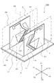
- FIG. 2 is a perspective view showing the relationship between the first antenna 1 and the second antenna 2.
- FIG. 3 is a diagram illustrating the relationship between the first frequency band, the second frequency band, and the third frequency band in the LTE system.
- FIG. 4 is a front view showing the shape of the first antenna element 11 in the first antenna 1
- FIG. 5 is a front view showing the shape of the second antenna element 12 in the second antenna 2.
- the antenna device 100 is an antenna device that supports the LTE system and also supports the MIMO system, and includes two antennas for the MIMO system that have a plurality of antenna elements used in the multiband frequency band of the LTE system. Each antenna can transmit and receive at the same frequency.
- the antenna device 100 is a miniaturized antenna device, and can maintain sufficient isolation between antennas even if the antenna device is miniaturized. The distance between the antennas is required to be closer, but the isolation between the antennas is required to be about 10 dB or more.
- the antenna device 100 is assumed to be mounted on a vehicle, and is used by being mounted on the roof of the vehicle.
- the antenna device 100 is housed in a case 31 having the shape of a cocoon ridge (shark fin shape) made of synthetic resin.
- the shark fin shape is a streamlined outer shape that becomes thinner toward the tip and has a curved side surface that is narrowed inward.
- the antenna device 100 includes a first antenna 1, a second antenna 2, and a ground plate 5.
- the first antenna 1 and the second antenna 2 are protected from the external environment by being covered with the case 31.
- the first antenna 1 and the second antenna 2 are connected to a communication device (not shown) in the vehicle by a cable 32, respectively.
- the ground plate 5 is mounted on a pedestal (not shown), and the pedestal is attached to the roof of the vehicle together with the ground plate 5 by screws or magnets.
- the ground plate 5 is a ground plane formed of metal, and may be formed of a metal foil pattern on the insulating substrate or of a metal plate.
- the ground plane can be extended from the ground plate 5 to the vehicle roof by connecting the ground plate 5 directly to the vehicle roof or by coupling it to the vehicle roof by capacitive coupling or the like. Therefore, the entire roof of the vehicle can be used as the ground of the antenna device 100, and the performance of the antenna device 100 can be improved.
- the antenna device 100 includes the above-described ground plate 5, the first antenna 1 provided on one surface side of the ground plate 5, and one surface side of the ground plate 5.
- the 2nd antenna 2 provided in is comprised as shown in FIG.
- the first antenna 1 includes a first insulating substrate 21 and a first antenna element 11 formed on the first insulating substrate 21.
- the second antenna 2 includes a second insulating substrate 22 and a second antenna element 12 formed on the second insulating substrate 22.
- the first insulating substrate 21 and the second insulating substrate 22 are mounted perpendicular to the ground plate 5 and face each other in parallel. That is, the first plane P1 formed by the first antenna 1 and the second plane P2 formed by the second antenna 2 face each other in parallel and stand upright with respect to the ground plate 5 respectively. ing. Further, the first insulating substrate 21 provided with the first antenna element 11 and the second insulating substrate 22 provided with the second antenna element 12, in other words, the first antenna 1 and the second antenna 2 are respectively connected between the antennas. They are mounted side by side at a distance L1.
- the antenna device 100 is configured to support the LTE system.
- the frequency band used for the LTE system is divided into three bands as shown in FIG.
- the lowest frequency band is the first frequency band of 0.7 GHz to 0.96 GHz
- the next frequency band is the second frequency band of 1.7 GHz to 2.2 GHz
- the highest frequency band Is the third frequency band of 2.5 GHz to 2.7 GHz. Therefore, the first antenna 1 and the second antenna 2 both have a first frequency band of 0.7 GHz to 0.96 GHz, a second frequency band of 1.7 GHz to 2.2 GHz, and a frequency band of 2.5 GHz to 2.7 GHz.
- the third frequency band signal can be transmitted and received.
- the first antenna 1 includes a first antenna element 11, a first feeding point 1a, and a first grounding point 1b formed on a first insulating substrate 21.
- the first antenna element 11 is a low-frequency first antenna element 11a, a parasitic first antenna element 11b, and a high-frequency first antenna element so that signals from the first frequency band to the third frequency band can be transmitted and received. 11c.
- the first antenna element 11a for low frequency includes an aggregate of a plurality of first conductor pieces 11d and is formed so as to handle a signal in the first frequency band that is the lowest frequency band in the LTE system.
- One end of one first conductor piece 11d of the plurality of first conductor pieces 11d is connected to the first feeding point 1a, and the other end of the first conductor piece 11d is another plurality of first conductor pieces. 11d is connected continuously.
- the parasitic first antenna element 11b also has one end of one first conductor piece 11d of the plurality of first conductor pieces 11d connected to the first ground point 1b, and the other end of the first conductor piece 11d. The other first conductor piece 11d is connected.
- each of the first conductor pieces 11d is formed to be inclined with respect to the normal line R1 of the ground plate 5. ing. That is, each first conductor piece 11d is neither parallel nor perpendicular to the perpendicular line R1.
- the first antenna element for low frequency 11a also has a conductor piece perpendicular to the perpendicular line R1 of the ground plate 5, but this conductor piece increases the inductance component of the parasitic first antenna element 11b. This is a conductor piece, not the first conductor piece 11d, and does not particularly contribute to the improvement of the isolation characteristics between the antennas.
- each first conductor piece 11d of the parasitic first antenna element 11b is provided along each first conductor piece 11d of the low-frequency first antenna element 11a.
- the parasitic first antenna element 11b is provided to widen the frequency band handled by the low-frequency first antenna element 11a, and is not connected to the first feeding point 1a. It is connected to the ground point 1b.
- Each first conductor piece 11d of the parasitic first antenna element 11b is connected to each first conductor piece 11d of the low-frequency first antenna element 11a, which is a feeding element, to the wavelength of the resonance frequency of the parasitic first antenna element 11b.
- the parasitic first antenna element 11b can be capacitively coupled to the low-frequency first antenna element 11a by keeping the distance at a very short distance. That is, the parasitic first antenna element 11b is fed from the first antenna element for low frequency 11a and becomes an antenna element having a new resonance frequency.
- the antenna length of the parasitic first antenna element 11b is set somewhat shorter than the antenna length of the low-frequency first antenna element 11a. Therefore, the new resonance frequency by the parasitic first antenna element 11b becomes higher than the resonance frequency of the low-frequency first antenna element 11a, and as a result, the frequency band by the low-frequency first antenna element 11a is expanded to the higher side. It becomes possible. That is, the frequency band by the low frequency first antenna element 11a can be widened.
- the high-frequency first antenna element 11c is configured such that one end of the conductor is connected to the first feeding point 1a and the width gradually increases from one end toward the open end.
- the first feeding point 1a has a substantially triangular shape with one vertex.
- the capacitance component is further increased.
- the resonance frequency decreases as the capacitance component increases. Therefore, when compared to a conductor whose open end is not wide, the antenna resonance frequency is small if the length of the antenna radiation conductor is the same. Become. That is, by widening the open end of the antenna, the length of the radiation conductor required for resonating at a desired frequency can be set shorter, so that the overall size of the antenna device can be reduced.
- the antenna length of the low-frequency first antenna element 11a is set to a length corresponding to the first frequency band, and specifically, is about 1 ⁇ 4 of the wavelength of the predetermined frequency signal in the first frequency band. Is set.
- the antenna length of the first antenna element for high frequency 11c is set to a length corresponding to a second frequency band having a frequency higher than that of the first frequency band. Specifically, a predetermined frequency signal in the second frequency band is set. Is set to about 1 ⁇ 4 of the wavelength.
- the first conductor piece 11d on the feeding point side of the low frequency first antenna element 11a is provided along the conductor of the high frequency first antenna element 11c.
- the impedance of the antenna element includes an inductance component determined by the length and width of the conductor of the antenna element, and a capacitance component generated between the conductor of the antenna element and the ground, or between the conductors of two adjacent antenna elements. Determined by.
- a capacitance component generated between the conductors of two adjacent antenna elements by adjusting the distance between the conductors of two adjacent antenna elements and adjusting the distance between the conductors of the two adjacent antenna elements. Can be adjusted. As a result, the impedance of each antenna element can be adjusted.
- the first conductor piece 11d of the first antenna element for low frequency 11a is provided along the conductor of the first antenna element for high frequency 11c, and the distance between the conductors and the length of each conductor are provided.
- each impedance matching is performed. This adjustment is performed at the design stage of the first antenna 1, and therefore the performance of the first antenna 1 is almost determined at the design stage.
- the antenna length of the low-frequency first antenna element 11a is configured to be able to transmit and receive a frequency band of 2.5 GHz to 2.7 GHz corresponding to a frequency band about three times the first frequency band, that is, the third frequency band. .
- the antenna length of the first antenna element 11a for low frequency is set to about 3 ⁇ 4 of the wavelength of the predetermined frequency signal in the third frequency band.
- the predetermined frequency in the third frequency band corresponds to a frequency about three times the predetermined frequency in the first frequency band.
- the antenna length of the first antenna element for low frequency 11a is set so that the first frequency band can be transmitted and received, and at the same time, the third frequency band corresponding to about three times the first frequency band is set. Is set to be able to send and receive. Therefore, transmission / reception in two frequency bands having significantly different frequencies can be realized with only one element. Therefore, it is possible to contribute to downsizing of the multiband antenna device 100.
- each of the conductor pieces of the first antenna element 11a for low frequency, each of the first conductor pieces 11d of the parasitic first antenna element 11b, and the first antenna element 11c for high frequency are made of a metal conductor.
- the metal conductor may be formed by a metal foil pattern on the first insulating substrate 21 shown in FIG. 4, or may be configured by cutting and combining metal plates without using an insulating substrate. May be.
- the second antenna 2 includes a second antenna element 12, a second feed point 2a, and a second ground point 2b formed on the second insulating substrate 22.
- the second antenna element 12 has a low-frequency second antenna element 12a, a parasitic second antenna element 12b, and a high-frequency second antenna element so that signals from the first frequency band to the third frequency band can be transmitted and received. 12c.
- the second antenna element 12a for low frequency includes an aggregate of a plurality of second conductor pieces 12d, and is formed so as to handle a signal in the first frequency band that is the lowest frequency band in the LTE system.
- One end of one second conductor piece 12d among the plurality of second conductor pieces 12d is connected to the first feeding point 1a, and the other end of the second conductor piece 12d is connected to the other plurality of second conductor pieces. 12d is connected continuously.
- one end of one second conductor piece 12d of the plurality of second conductor pieces 12d is connected to the second ground point 2b, and the other end of the second conductor piece 12d is connected to the other end of the second conductor piece 12d.
- the other second conductor piece 12d is connected.
- the high-frequency second antenna element 12c is configured such that one end of the conductor is connected to the second feeding point 2a and the width gradually increases from one end toward the open end.
- the second feeding point 2a has a substantially triangular shape with one vertex.
- the second antenna element 12 including the low-frequency second antenna element 12a, the parasitic second antenna element 12b, and the high-frequency second antenna element 12c has a shape when the second antenna element 12 is turned upside down. It is configured to be congruent with the shape of the first antenna element 11. In other words, when the second antenna element 12 is turned over in the left-right direction and overlapped with the first antenna element 11, each antenna element appears to be completely overlapped. As a result, only one antenna element exists.
- the second antenna element 12 is configured to look like this.
- the shape when the second antenna element 12 is turned upside down is configured to be the same as the shape of the first antenna element 11. Therefore, in the second antenna element 12, the low frequency second antenna element 12a corresponds to the low frequency first antenna element 11a, the parasitic second antenna element 12b corresponds to the parasitic first antenna element 11b, and the high frequency
- the second antenna element 12c for use corresponds to the first antenna element 11c for high frequency.
- the second feeding point 2 a of the second antenna 2 corresponds to the first feeding point 1 a of the first antenna 1
- the second grounding point 2 b of the second antenna 2 corresponds to the first grounding point 1 b of the first antenna 1.
- the function of each antenna element of the second antenna element 12 is exactly the same as the function of each antenna element of the first antenna element 11. Therefore, the further description about the 2nd antenna 2 is abbreviate
- FIG. 6 is a front view when the first antenna 1 and the second antenna 2 are viewed in an overlapping manner
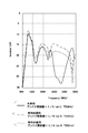
- FIG. 7 is a graph showing the isolation characteristics between the antennas of the antenna device 100 of the present invention.
- the first conductor piece 11d and the second conductor piece 12d of each of the first antenna element 11 and the second antenna element 12 are not parallel to the perpendicular line R1 or perpendicular line R2 of the ground plate 5 but perpendicular to each other. Absent. Therefore, as shown in FIG. 6, when the first antenna 1 and the second antenna 2 are viewed in parallel with each other, the first conductor piece 11d and the second conductor piece 12d corresponding to each other are perpendicular to each other. Alternatively, the directions are opposite to each other with respect to the perpendicular line R2.
- the first conductor piece 11d and the second conductor piece 12d of the first antenna element 11 and the second antenna element 12 respectively correspond to each other.
- Some of the first conductor piece 11d and the second conductor piece 12d have a right angle.
- the second conductor element 11d from the first feeding point 1a and the second antenna element 12a for low frequency are second from the second feeding point 2a.
- the angle ⁇ formed by the third first conductor piece 11d from the first feeding point 1a and the third second conductor piece 12d from the second feeding point 2a is an angle ⁇ ⁇ 90 °. This is to extend the first conductor piece 11d and the second conductor piece 12d in the upward direction in order to ensure antenna characteristics other than the isolation between the antennas.
- the shape when the second antenna element 12 is turned over is set to be the same as the shape of the first antenna element 11. Therefore, when the first antenna 1 and the second antenna 2 are viewed in an overlapped manner, the first conductor piece 11d and the second conductor piece 12d corresponding to each other are at an angle of 45 ° with respect to the perpendicular R1 or the perpendicular R2, respectively. It is set to make.
- the antenna performance of each antenna can be ensured by setting the distance between the antennas of the two antennas mounted in parallel to 1/4 or more of the wavelength of the handled frequency. Therefore, the inter-antenna distance L1 between the first antenna 1 and the second antenna 2 shown in FIG. 2 is normally set to 1 ⁇ 4 of the wavelength of the signal near the lowest frequency of the handled frequency. In the LTE system, since 0.7 GHz is the lowest frequency, the inter-antenna distance L1 is set to 1 ⁇ 4 ( ⁇ / 4) of the wavelength of the signal in the vicinity of 0.7 GHz.
- the dimension is about 100 mm. That is, if the inter-antenna distance L1 is set to about 100 mm, the antenna performance near that frequency can be ensured. For frequencies higher than 0.75 GHz, the antenna distance L1 is necessarily 1 ⁇ 4 or more of the wavelength of the signal, so that the antenna performance can be ensured.
- the isolation between the antennas is 10 dB or more without applying the present invention. Sufficient characteristics have been obtained. However, when the present invention is not applied and the distance between the two antennas is set to 1/6 ( ⁇ / 6) of the wavelength of the signal of 0.75 GHz, that is, set to be shortened to about 67 mm, As shown by the alternate long and short dash line in FIG. 7, it is confirmed that the isolation characteristics between the antennas deteriorate. In the case of about 0.8 GHz or more, it is considered that there is no problem because it is 10 dB or more. However, in the band of 0.7 GHz to 0.8 GHz, 10 dB is cut, and sufficient isolation characteristics between antennas cannot be obtained. I understand.
- the inter-antenna isolation between the first antenna 1 and the second antenna 2 is about 10 dB. This is substantially equivalent to the case where the inter-antenna distance L1 between the first antenna 1 and the second antenna 2 is set to 1 ⁇ 4 of the wavelength of the signal of 0.75 GHz without applying the present invention. Further, without applying the present invention, the antenna distance L1 between the first antenna 1 and the second antenna 2 is improved by about 2 dB as compared with the case where the wavelength of the signal of 0.75 GHz is set to 1/6. ing.
- the antenna device 100 is an antenna obtained when the inter-antenna distance L1 between the first antenna 1 and the second antenna 2 is set to 1/4 (100 mm) of the wavelength of the signal of 0.75 GHz.
- the inter-antenna isolation characteristic can be obtained even when the distance L1 between the antennas is shortened to 1/6 (67 mm) of the wavelength of the signal of 0.75 GHz.
- the size of the antenna device 100 main body in the Y1-Y2 direction is reduced by 33 mm, that is, 33%, while maintaining the required inter-antenna isolation characteristics between the first antenna 1 and the second antenna 2. Can do.
- the antenna device 100 when the first antenna 1 and the second antenna 2 are viewed with being overlapped, the first conductor piece 11d and the second conductor piece 12d corresponding to each other are connected to the perpendicular R1 or the perpendicular R2. So that they face in opposite directions. Therefore, the antenna polarization planes of the first conductor piece 11d and the second conductor piece 12d corresponding to each other can be crossed. As a result, the coupling between the first conductor piece 11d and the second conductor piece 12d corresponding to each other can be reduced, and even when the antenna device 100 main body is downsized, the first antenna 1 and the second antenna 2 can be reduced. The required inter-antenna isolation characteristics can be maintained.
- the angle between the first conductor piece 11d and the second conductor piece 12d corresponding to each other is set to be a right angle, so that the first conductors corresponding to each other are set.
- the antenna polarization planes of the piece 11d and the second conductor piece 12d can be orthogonal to each other. As a result, the coupling between the first conductor piece 11d and the second conductor piece 12d corresponding to each other can be further reduced, and the inter-antenna isolation between the first antenna 1 and the second antenna 2 can be further increased. it can.
- the characteristics of the first antenna 1 and the second antenna 2 are made the same.
- the inter-antenna isolation between the first antenna 1 and the second antenna 2 can be maximized.
- the first conductor piece and the second conductor piece corresponding to each other are connected to the perpendicular of the ground plate. Since they are configured to face in opposite directions, the antenna polarization planes of the first conductor piece and the second conductor piece corresponding to each other can intersect each other. As a result, the coupling between the first conductor piece and the second conductor piece corresponding to each other can be reduced, and even when the antenna device body is downsized, it is required between the first antenna and the second antenna. The isolation characteristics between antennas can be maintained.
- the antenna device 100 As described above, the antenna device 100 according to the embodiment of the present invention has been described. However, the present invention is not limited to the above-described embodiment, and various modifications can be made without departing from the scope of the invention. It is.
Landscapes
- Engineering & Computer Science (AREA)
- Computer Networks & Wireless Communication (AREA)
- Variable-Direction Aerials And Aerial Arrays (AREA)
- Details Of Aerials (AREA)
Abstract
【課題】複数のアンテナ素子が設けられたアンテナを2つ有する場合に、装置本体が小型化されても、アイソレーション特性を維持できるアンテナ装置を提供する。 【解決手段】グランド板5と第1アンテナ1と第2アンテナ2とを備えたアンテナ装置100であって、第1アンテナ1は、第1アンテナ素子11を有し、第1アンテナ素子11はグランド板の垂線R1に対して平行ではなく垂直でもない複数の第1導体片11dの集合体を含み、第2アンテナ2は、第2アンテナ素子12を有し、第2アンテナ素子12は垂線R2に対して平行ではなく垂直でもない複数の第2導体片12dの集合体を含み、第1アンテナ1と第2アンテナ2とを重ねて見た時に、互いに対応する第1導体片11dと第2導体片12dとが、垂線R1又は垂線R2に対して互いに逆方向に向いている。
Description
本発明は、通信用のアンテナ装置に係り、特に複数のアンテナを有するアンテナ装置に関する。
近年、無線通信ネットワークにおいては、周波数利用効率の向上、データレートの向上を目的として、LTE(Long Term Evolution)システムが世界中で実用化されようとしている。LTEシステムにおいては、互いに異なる複数の周波数帯域を用いてデータの送受信を行なうことが決められている。このようなシステムでは、複数の周波数帯域に対応するため複数のアンテナ素子を同一絶縁基板上に有したアンテナ装置が用いられる。
また、最近では、2つのアンテナを組み合わせてデータの送受信を行い、利用できる周波数帯域を擬似的に広げるMIMO(Multiple Input Multiple Output)と呼ばれる技術が開発されている。このような技術を利用したシステムにおいては、同一周波数で送受信可能な2つのアンテナを互いの近傍に設置したアンテナ装置が用いられる。
複数のアンテナ素子を同一絶縁基板上に有する場合、又は2つのアンテナを互いの近傍に設置した場合において、互いのアンテナ素子間又は互いのアンテナ間のアイソレーションを十分確保することが要求される。また、最近では、アンテナ装置の小型化も要求されるようになってきている。
そこで、このような要求に対し、特許文献1によるアンテナ装置900のような、隣接した周波数帯域に対応する複数のアンテナ素子を有し、複数のアンテナ素子間のアイソレーション特性を改善したアンテナ装置が提案されている。特許文献1によるアンテナ装置について、図8を用いて説明する。
アンテナ装置900は、地板910と、第1の周波数帯域に対応する第1のアンテナ素子911と、第1の周波数帯域の近傍又は第1の周波数帯域と重なる第2の周波数帯域に対応する第2のアンテナ素子912と、第1のアンテナ素子911に給電を行う第1の給電部913と、第2のアンテナ素子912に給電を行う第2の給電部914とを備える。そして、第1のアンテナ素子911を地板910の長辺に対して直交する方向に配置すると共に、第2のアンテナ素子912を地板910の長辺に対して平行な方向に配置する構成とした。
アンテナ装置900では、第1のアンテナ素子911と第2のアンテナ素子912の配置を互いに直交するように配置することにより、アンテナ素子間の結合を低減させることができ、アンテナ素子間のアイソレーション特性を改善することができるとしている。
特許文献1に開示されたような、複数の周波数帯域に対応するために複数のアンテナ素子が設けられたアンテナが1つのみである場合、複数のアンテナ素子間のアイソレーションを確保することは、特許文献1に開示された発明による技術で対応できる。しかしながら、複数の周波数帯域に対応するために複数のアンテナ素子が設けられたアンテナを、2つ有するように配置したアンテナ装置である場合、特許文献1に開示された発明による技術だけでは、装置本体が小型化された場合に、アンテナ間アイソレーション特性を維持することは困難であった。
本発明は、このような従来技術の実情に鑑みてなされたもので、その目的は、複数のアンテナ素子が設けられたアンテナを2つ有する場合に、装置本体が小型化されても、必要とされるアンテナ間アイソレーション特性を維持できるアンテナ装置を提供することにある。
この課題を解決するために、本発明のアンテナ装置は、グランド板と、前記グランド板の一方の面側に設けられた第1アンテナと、前記グランド板の一方の面側に設けられた第2アンテナと、を備えたアンテナ装置であって、前記第1アンテナによって形成される第1平面と前記第2アンテナによって形成される第2平面とは互いに平行に対面していると共に、前記グランド板に対してそれぞれ垂直に立設しており、前記第1アンテナは、第1アンテナ素子を有し、前記第1アンテナ素子は前記グランド板の垂線に対して平行ではなく垂直でもない複数の第1導体片の集合体を含み、前記第2アンテナは、第2アンテナ素子を有し、前記第2アンテナ素子は前記垂線に対して平行ではなく垂直でもない複数の第2導体片の集合体を含み、前記第1アンテナと前記第2アンテナとを重ねて見た時に、互いに対応する前記第1導体片と前記第2導体片とが、前記垂線に対して互いに逆方向に向いている、という特徴を有する。
このように構成されたアンテナ装置では、第1アンテナと第2アンテナとを重ねて見た時に、互いに対応する第1導体片と第2導体片とを、グランド板の垂線に対して互いに逆方向に向くように構成したため、互いに対応する第1導体片及び第2導体片それぞれのアンテナ偏波面同士を交差させることができる。その結果、互いに対応する第1導体片と第2導体片との結合を低減させることができ、アンテナ装置本体を小型化した場合においても、第1アンテナと第2アンテナとの間の必要とされるアンテナ間アイソレーション特性を維持することができる。
また、上記の構成において、前記第1アンテナと前記第2アンテナとを重ねて見た時に、互いに対応する前記第1導体片と前記第2導体片とのなす角度が直角である、という特徴を有する。
このように構成されたアンテナ装置では、第1アンテナと第2アンテナとを重ねて見た時に、互いに対応する第1導体片と第2導体片とのなす角度を直角に設定したので、互いに対応する第1導体片及び第2導体片それぞれのアンテナ偏波面同士を直交させることができる。その結果、互いに対応する第1導体片と第2導体片との結合を更に低減させることができ、第1アンテナと第2アンテナとの間のアンテナ間アイソレーションを更に高めることができる。
また、上記の構成において、前記第2アンテナ素子を裏返した時の形状が前記第1アンテナ素子の形状と合同であって、前記第1アンテナと前記第2アンテナとを重ねて見た時に、互いに対応する前記第1導体片と前記第2導体片とが、前記垂線に対してそれぞれ45°の角度を有する、という特徴を有する。
このように構成されたアンテナ装置では、第1アンテナと第2アンテナとの各特性を同一にすることができると共に、第1アンテナと第2アンテナとの間のアンテナ間アイソレーションを最大限に高めることができる。
本発明のアンテナ装置は、第1アンテナと第2アンテナとを重ねて見た時に、互いに対応する第1導体片と第2導体片とを、グランド板の垂線に対して互いに逆方向に向くように構成したため、互いに対応する第1導体片及び第2導体片それぞれのアンテナ偏波面同士を交差させることができる。その結果、互いに対応する第1導体片と第2導体片との結合を低減させることができ、アンテナ装置本体を小型化した場合においても、第1アンテナと第2アンテナとの間の必要とされるアンテナ間アイソレーション特性を維持することができる。
[実施形態]
以下、本発明の実施形態について、図面を参照しながら説明する。尚、本明細書では、特に断りの無い限り、各図面のX1側を右側、X2側を左側、Y1側を奥側、Y2側を手前側、Z1側を上側、Z2側を下側として説明する。
以下、本発明の実施形態について、図面を参照しながら説明する。尚、本明細書では、特に断りの無い限り、各図面のX1側を右側、X2側を左側、Y1側を奥側、Y2側を手前側、Z1側を上側、Z2側を下側として説明する。
最初に、実施形態に係るアンテナ装置100の外観形状、及び第1アンテナ1と第2アンテナ2それぞれにおける第1アンテナ素子11と第2アンテナ素子12の構成について図1乃至図5を用いて説明する。
図1は、実施形態に係るアンテナ装置100の最終的な外観を示す斜視図であり、図2は、第1アンテナ1と第2アンテナ2との関係を示す斜視図である。また、図3は、LTEシステムにおける第1周波数帯域、第2周波数帯域、第3周波数帯域の各周波数帯域の関係を示す図である。更に、図4は、第1アンテナ1における第1アンテナ素子11の形状を示す正面図であり、図5は、第2アンテナ2における第2アンテナ素子12の形状を示す正面図である。
アンテナ装置100は、LTEシステムに対応すると共に、MIMOシステムにも対応したアンテナ装置であり、LTEシステムのマルチバンド周波数帯域に使用されるアンテナ素子を複数有するアンテナをMIMOシステム用に2つ備えていて、それぞれのアンテナは同一周波数で送受信可能となっている。アンテナ装置100は、小型化されたアンテナ装置であり、小型化されても十分なアンテナ間アイソレーションを維持することのできるアンテナ装置である。アンテナ間距離としては、より近接させることが要求されるが、アンテナ間アイソレーションとしては約10dB以上が必要とされる。また、アンテナ装置100は、車載用を想定しており、車両のルーフ上に取り付けられて使用される。
図1に示すように、アンテナ装置100は、合成樹脂で形成された鮫の鰭の形状(シャークフィン形状)を持ったケース31内に収納されている。シャークフィン形状は、先端に行くほど細くなると共に、側面も内側に絞った曲面とされた流線型の外形形状となっている。アンテナ装置100は、第1アンテナ1と第2アンテナ2とグランド板5とを有している。第1アンテナ1と第2アンテナ2とは、ケース31で覆われることにより外部の環境から保護されることになる。また、第1アンテナ1と第2アンテナ2とはケーブル32によって車両内の通信機器(図示せず)にそれぞれ接続される。
グランド板5は台座(図示せず)に搭載され、台座はグランド板5と共に車両の屋根に、ネジ留めや磁石等によって取り付けられる。グランド板5は、金属によって形成されたグランドプレーンであって、絶縁基板上に金属箔パターンで形成されていても良いし、金属板によって形成されても良い。グランド板5を車両の屋根に直接接続するか、又は静電容量結合等によって車両の屋根に結合させることによって、グランド板5から車両の屋根へグランドプレーンを拡張させることができる。そのため、車両の屋根全体をアンテナ装置100のグランドとして使用することができ、アンテナ装置100の性能向上に貢献させることができる。
アンテナ装置100は、図1で示したケース31の内部において、前述したグランド板5と、グランド板5の一方の面側に設けられた第1アンテナ1と、同じくグランド板5の一方の面側に設けられた第2アンテナ2とが、図2に示すように構成されている。第1アンテナ1は、第1絶縁基板21と、第1絶縁基板21上に形成された第1アンテナ素子11とを有して構成されている。また、第2アンテナ2は、第2絶縁基板22と、第2絶縁基板22上に形成された第2アンテナ素子12とを有して構成されている。
第1絶縁基板21と第2絶縁基板22とは、それぞれグランド板5に対して垂直に取り付けられていると共に、互いに平行に対面している。即ち、第1アンテナ1によって形成される第1平面P1と第2アンテナ2によって形成される第2平面P2とは互いに平行に対面していると共に、グランド板5に対してそれぞれ垂直に立設している。また、第1アンテナ素子11が設けられた第1絶縁基板21と第2アンテナ素子12が設けられた第2絶縁基板22、言い換えれば、第1アンテナ1と第2アンテナ2とは、それぞれアンテナ間距離L1だけ離れて真横に並んで取り付けられている。
前述したように、アンテナ装置100は、LTEシステムに対応するように構成されている。LTEシステムに用いられる周波数帯域は、図3に示すように、3つの帯域に分かれている。最も周波数の低い周波数帯域が、0.7GHz~0.96GHzの第1周波数帯域であり、次の周波数帯域が、1.7GHz~2.2GHzの第2周波数帯域であり、最も周波数の高い周波数帯域が、2.5GHz~2.7GHzの第3周波数帯域である。そのため、第1アンテナ1及び第2アンテナ2は、どちらも0.7GHz~0.96GHzの第1周波数帯域、1.7GHz~2.2GHzの第2周波数帯域、及び2.5GHz~2.7GHzの第3周波数帯域の信号を送受信できるように構成されている。
図4に示すように、第1アンテナ1は、第1絶縁基板21上に構成された第1アンテナ素子11、第1給電点1a、及び第1接地点1bで構成されている。第1アンテナ素子11は、上記第1周波数帯域から第3周波数帯域までの信号を送受信できるように、低周波用第1アンテナ素子11a、無給電第1アンテナ素子11b、及び高周波用第1アンテナ素子11cで構成されている。
低周波用第1アンテナ素子11aは、複数の第1導体片11dの集合体を含み、LTEシステムにおける最も周波数の低い周波数帯域である第1周波数帯域の信号を取り扱うように形成されている。複数の第1導体片11dの内の1つの第1導体片11dの一端が第1給電点1aに接続されていて、その第1導体片11dの他端には他の複数の第1導体片11dが連続して接続されている。無給電第1アンテナ素子11bも、複数の第1導体片11dの内の1つの第1導体片11dの一端が第1接地点1bに接続されていて、その第1導体片11dの他端には他の第1導体片11dが接続されている。
低周波用第1アンテナ素子11a及び無給電第1アンテナ素子11bを構成している導体片の内、各第1導体片11dは、全て、グランド板5の垂線R1に対して傾斜して形成されている。即ち、各第1導体片11dは、垂線R1に対して平行でもなく垂直でもない。尚、低周波用第1アンテナ素子11aには、グランド板5の垂線R1に対して垂直な導体片も存在するが、この導体片は、無給電第1アンテナ素子11bのインダクタンス成分を増加させるための導体片であり、第1導体片11dではなく、アンテナ間アイソレーション特性の改善には特に寄与していない。
図4からわかるように、無給電第1アンテナ素子11bの各第1導体片11dが低周波用第1アンテナ素子11aの各第1導体片11dに沿って設けられている。無給電第1アンテナ素子11bは、低周波用第1アンテナ素子11aによって取り扱われる周波数帯域を広帯域化するために設けられたものであり、第1給電点1aには接続されておらず、第1接地点1bに接続されている。無給電第1アンテナ素子11bの各第1導体片11dを、給電素子である低周波用第1アンテナ素子11aの各第1導体片11dに、無給電第1アンテナ素子11bの共振周波数の波長に比べて非常に短い離間距離で沿わせることにより、無給電第1アンテナ素子11bを低周波用第1アンテナ素子11aに容量結合させることができる。即ち、無給電第1アンテナ素子11bは、低周波用第1アンテナ素子11aから給電されて、新たな共振周波数を有するアンテナ素子となる。
無給電第1アンテナ素子11bのアンテナ長は、低周波用第1アンテナ素子11aのアンテナ長に比べて幾分短く設定されている。従って、無給電第1アンテナ素子11bによる新たな共振周波数は、低周波用第1アンテナ素子11aの共振周波数より高くなり、結果として、低周波用第1アンテナ素子11aによる周波数帯域を高いほうに拡げることが可能となる。即ち、低周波用第1アンテナ素子11aによる周波数帯域を広帯域化することができる。
高周波用第1アンテナ素子11cは、その導体の一端が第1給電点1aに接続されていると共に、一端から開放端に向かって、その幅が漸次広くなるように構成されていて、その形状は、第1給電点1aを1つの頂点とする略三角形状となっている。
高周波用第1アンテナ素子11cの導体のうち最も電界強度の強いアンテナ開放端部が幅広に形成してあるので、キャパシタンス成分がより増大することとなる。そして一般的に共振回路では、キャパシタンス成分が大きくなると共振周波数が小さくなるので、開放端が幅広になっていない導体と比べたとき、アンテナ放射導体の長さが同等であればアンテナ共振周波数が小さくなる。即ち、アンテナ開放端部を幅広にすることによって、所望の周波数に共振させるうえで必要となる放射導体の長さをより短く設定することができるので、アンテナ装置全体の寸法を低減できる。
低周波用第1アンテナ素子11aのアンテナ長は、第1周波数帯域に対応した長さに設定されており、具体的には、第1周波数帯域内における所定周波数信号の波長の約1/4に設定されている。また、高周波用第1アンテナ素子11cのアンテナ長は、第1周波数帯域より周波数の高い第2周波数帯域に対応した長さに設定されており、具体的には、第2周波数帯域における所定周波数信号の波長の約1/4に設定されている。
低周波用第1アンテナ素子11aの給電点側の第1導体片11dは、高周波用第1アンテナ素子11cの導体に沿って設けられている。一般的に、アンテナ素子の導体同士を近接させて配置することにより、互いのインピーダンスマッチングを行なうことが可能となる。アンテナ素子のインピーダンスは、アンテナ素子の導体の長さ及び幅によって決定されるインダクタンス成分と、アンテナ素子の導体とグランド間、又は、隣り合う2個のアンテナ素子それぞれの導体間に発生するキャパシタンス成分とによって決定する。特に、隣り合う2個のアンテナ素子の導体同士を近接させ、その離間距離及び対向させている導体の長さを調整することにより、隣り合う2個のアンテナ素子それぞれの導体間に発生するキャパシタンス成分を調整することができる。その結果、それぞれのアンテナ素子のインピーダンスを調整することができる。
第1アンテナ1においては、低周波用第1アンテナ素子11aの第1導体片11dを、高周波用第1アンテナ素子11cの導体に沿って設け、それぞれの導体間の離間距離及び各導体の長さを調整することによって、それぞれのインピーダンスマッチングを行なうようにしている。尚、この調整は、第1アンテナ1の設計段階において実施されるものであり、そのため第1アンテナ1の性能は、設計段階でほぼ決定されることになる。
低周波用第1アンテナ素子11aのアンテナ長は、第1周波数帯域の約3倍の周波数帯域に当たる2.5GHzから2.7GHzの周波数帯域、即ち第3周波数帯域も送受信できるように構成されている。具体的には、低周波用第1アンテナ素子11aのアンテナ長は、第3周波数帯域の中の所定周波数信号の波長の約3/4に設定されている。ここで、上記第3周波数帯域の中の所定周波数は、上記第1周波数帯域の中の所定周波数の約3倍の周波数に相当する。
上記のように、低周波用第1アンテナ素子11aのアンテナ長は、第1周波数帯域を送受信できるように設定されていると同時に、第1周波数帯域の約3倍の周波数に当たる第3周波数帯域をも送受信できるように設定されていることになる。そのため、周波数の大きく異なる2つの周波数帯域の送受信を、1つの素子だけで実現することができる。従って、マルチバンド対応のアンテナ装置100の小型化に貢献することができる。
尚、図4において、低周波用第1アンテナ素子11aの各導体片と無給電第1アンテナ素子11bの各第1導体片11dと高周波用第1アンテナ素子11cとは、金属製の導体からなる。この金属製の導体は、図4に示した第1絶縁基板21上に金属箔パターンによって形成されたものでも良いし、絶縁基板を使用せず、金属板を切り抜いて組み合わせた構成のものであっても良い。
図5に示すように、第2アンテナ2は、第2絶縁基板22上に構成された第2アンテナ素子12、第2給電点2a、及び第2接地点2bで構成されている。第2アンテナ素子12は、上記第1周波数帯域から第3周波数帯域までの信号を送受信できるように、低周波用第2アンテナ素子12a、無給電第2アンテナ素子12b、及び高周波用第2アンテナ素子12cで構成されている。
低周波用第2アンテナ素子12aは、複数の第2導体片12dの集合体を含み、LTEシステムにおける最も周波数の低い周波数帯域である第1周波数帯域の信号を取り扱うように形成されている。複数の第2導体片12dの内の1つの第2導体片12dの一端が第1給電点1aに接続されていて、その第2導体片12dの他端には他の複数の第2導体片12dが連続して接続されている。無給電第2アンテナ素子12bも、複数の第2導体片12dの内の1つの第2導体片12dの一端が第2接地点2bに接続されていて、その第2導体片12dの他端には他の第2導体片12dが接続されている。
高周波用第2アンテナ素子12cは、その導体の一端が第2給電点2aに接続されていると共に、一端から開放端に向かって、その幅が漸次広くなるように構成されていて、その形状は、第2給電点2aを1つの頂点とする略三角形状となっている。
低周波用第2アンテナ素子12a、無給電第2アンテナ素子12b、及び高周波用第2アンテナ素子12cを含む第2アンテナ素子12は、第2アンテナ素子12を左右方向に裏返した時の形状が、第1アンテナ素子11の形状と合同になるように構成されている。言い換えれば、第2アンテナ素子12を左右方向に裏返して、第1アンテナ素子11と重ねて見た時に、各アンテナ素子が完全に重なって見えることになり、結果として、1つのアンテナ素子だけが存在するように見えるように、第2アンテナ素子12が構成されている。
上述のように、第2アンテナ素子12を左右方向に裏返した時の形状が、第1アンテナ素子11の形状と合同になるように構成されている。そのため、第2アンテナ素子12において、低周波用第2アンテナ素子12aが低周波用第1アンテナ素子11aに対応し、無給電第2アンテナ素子12bが無給電第1アンテナ素子11bに対応し、高周波用第2アンテナ素子12cが高周波用第1アンテナ素子11cに対応する。また、第2アンテナ2の第2給電点2aが第1アンテナ1の第1給電点1aに相当し、第2アンテナ2の第2接地点2bが第1アンテナ1の第1接地点1bに相当する。従って、第2アンテナ素子12の各アンテナ素子の働きは、第1アンテナ素子11の各アンテナ素子の働きと全く同等である。よって、第2アンテナ2についてのこれ以上の説明は省略する。
次に、図2、図6及び図7を用いて第1アンテナ1と第2アンテナ2との取り付け構造について説明する。図6は、第1アンテナ1と第2アンテナ2とを重ねて見た時の正面図であり、図7は、本発明のアンテナ装置100のアンテナ間アイソレーション特性を示すグラフである。
図2に示すように、第1アンテナ素子11及び第2アンテナ素子12それぞれの第1導体片11d及び第2導体片12dは、グランド板5の垂線R1又は垂線R2に対して平行ではなく垂直でもない。そのため、図6に示すように、第1アンテナ1と第2アンテナ2とを平行に移動して重ねて見た時に、互いに対応する第1導体片11dと第2導体片12dとがそれぞれ垂線R1又は垂線R2に対して互いに逆方向に向くことになる。互いに対応する第1導体片11dと第2導体片12dとをそれぞれ垂線R1又は垂線R2に対して互いに逆方向に向かせることにより、それぞれの間のアイソレーションを改善させることができる。
また、第1アンテナ1と第2アンテナ2とを重ねて見た時に、第1アンテナ素子11及び第2アンテナ素子12それぞれの各第1導体片11d及び各第2導体片12dの内、互いに対応する第1導体片11dと第2導体片12dとのなす角度が直角となっているものがある。例えば、図6に示す低周波用第1アンテナ素子11aの、第1給電点1aから2つめの第1導体片11dと低周波用第2アンテナ素子12aの、第2給電点2aから2つめの第2導体片12dとのなす角度αを、角度α=90°としている。角度α=90°とすることにより、互いに対応する第1導体片11dと第2導体片12dとの間のアイソレーションを更に改善させることができる。
第1給電点1aから3つめの第1導体片11dと第2給電点2aから3つめの第2導体片12dとのなす角度βは、角度β<90°となっている。これは、アンテナ間アイソレーション以外のアンテナ特性を確保するために、これらの第1導体片11dと第2導体片12dとを、より上側方向に伸ばすようにするためである。角度βは、種々のアンテナ特性をそれぞれバランス良く得るためにその値が選択される。尚、アンテナ間アイソレーションを良くするためには、角度β>45°が好ましく、角度β=90°が最も好ましい。
更に、アンテナ装置100では、第2アンテナ素子12を裏返した時の形状が、第1アンテナ素子11の形状と合同となるように設定した。そのため、第1アンテナ1と第2アンテナ2とを重ねて見た時に、互いに対応する第1導体片11dと第2導体片12dとが、それぞれ垂線R1又は垂線R2に対してそれぞれ45°の角度をなすように設定される。例えば、図6に示す無給電第1アンテナ素子11bの、第1接地点1bから1つめの第1導体片11dと垂線R1とのなす角度γ1と、無給電第2アンテナ素子12bの、第2接地点2bから1つめの第2導体片12dと垂線R2とのなす角度γ2との関係は、角度γ1=角度γ2=45°となる。
次に、第1アンテナ1と第2アンテナ2とをグランド板5上に取り付けた時の、アンテナ間距離L1について、図2を用いて説明する。
一般的に、平行に取り付けられた2つのアンテナのアンテナ間距離は、取り扱う周波数の波長の1/4以上に設定することによってそれぞれのアンテナのアンテナ性能を確保することができる。従って、図2に示す第1アンテナ1と第2アンテナ2との間のアンテナ間距離L1は、通常、取り扱う周波数の最低周波数近辺の信号の波長の1/4に設定することになる。LTEシステムでは、0.7GHzが最低周波数となるため、アンテナ間距離L1は、0.7GHz近辺の信号の波長の1/4(λ/4)に設定することになる。
例えば、0.7GHz近辺の信号として0.75GHzの信号を選択し、アンテナ間距離L1を0.75GHzの信号の波長の1/4に設定した場合、その寸法は約100mmとなる。即ち、アンテナ間距離L1を約100mmに設定すれば、その周波数近辺のアンテナ性能を確保することができる。尚、0.75GHzより高い周波数については、アンテナ間距離L1が必然的にその信号の波長の1/4以上になるため、アンテナ性能を確保することができる。
しかし、アンテナ装置として小型化が要求された場合、アンテナ間距離を短くすることが必要となってくる。そこで、本発明のアンテナ装置100では、第1アンテナ1及び第2アンテナ2との間のアンテナ間距離L1(図2参照)を、アンテナ装置100本体の形状を小さくするため、0.75GHzの信号の波長の1/6、即ちL1=λ/6=約67mmに設定した。その場合の第1アンテナ1及び第2アンテナ2との間のアンテナ間アイソレーションのデータを図7の実線で示す。尚、比較のため、本発明を適用せず、第2アンテナ2を裏返して取り付けた場合、即ち同一方向から第1アンテナ1と第2アンテナ2とを重ねて見た時に、アンテナ素子の形状が完全に重なって見えるように取り付けた場合で、L1=λ/4=約100mmに設定した時のアンテナ間アイソレーションのデータを図7の破線で示す。また、同じく本発明を適用せず、第2アンテナ2を裏返して取り付けた場合で、L1=λ/6=約67mmに設定した時のアンテナ間アイソレーションのデータを図7の一点鎖線で示す。
図7の破線で示すように、0.75GHzの信号の波長の1/4(λ/4)に設定した場合には、本発明を適用しなくても、アンテナ間アイソレーションは10dB以上であり、十分な特性が得られている。しかし、本発明を適用せず、2つのアンテナ間の距離を、0.75GHzの信号の波長の1/6(λ/6)に設定した場合、即ち約67mmまで短くなるように設定した場合、図7の一点鎖線で示すように、アンテナ間アイソレーション特性が悪化することが確認される。約0.8GHz以上の場合は10dB以上であるため問題ないと考えられるが、0.7GHz~0.8GHzの帯域では10dBを切っており、十分なアンテナ間アイソレーション特性を得られていないことが分かる。
図7の実線で示すように、本発明を適用した場合、第1アンテナ1と第2アンテナ2との間のアンテナ間アイソレーションは約10dBである。これは、本発明を適用せずに、第1アンテナ1と第2アンテナ2との間のアンテナ間距離L1を0.75GHzの信号の波長の1/4に設定した場合とほぼ同等である。また、本発明を適用せずに、第1アンテナ1と第2アンテナ2との間のアンテナ間距離L1を0.75GHzの信号の波長の1/6に設定した場合に対して約2dB改善されている。
従って、本発明によるアンテナ装置100は、第1アンテナ1と第2アンテナ2との間のアンテナ間距離L1を0.75GHzの信号の波長の1/4(100mm)に設定した場合に得られるアンテナ間アイソレーション特性を、アンテナ間距離L1を0.75GHzの信号の波長の1/6(67mm)に短くした場合においても得ることができる。言い換えれば、第1アンテナ1と第2アンテナ2との間の必要とされるアンテナ間アイソレーション特性を維持したまま、アンテナ装置100本体のY1-Y2方向の寸法を33mm、即ち33%小さくすることができる。
このように、アンテナ装置100では、第1アンテナ1と第2アンテナ2とを重ねて見た時に、互いに対応する第1導体片11dと第2導体片12dとを、垂線R1又は垂線R2に対して互いに逆方向に向くように構成した。そのため、互いに対応する第1導体片11d及び第2導体片12dそれぞれのアンテナ偏波面同士を交差させることができる。その結果、互いに対応する第1導体片11dと第2導体片12dとの結合を低減させることができ、アンテナ装置100本体を小型化した場合においても、第1アンテナ1と第2アンテナ2との間の必要とされるアンテナ間アイソレーション特性を維持することができる。
また、第1アンテナ1と第2アンテナ2とを重ねて見た時に、互いに対応する第1導体片11dと第2導体片12dとのなす角度を直角に設定したので、互いに対応する第1導体片11d及び第2導体片12dそれぞれのアンテナ偏波面同士を直交させることができる。その結果、互いに対応する第1導体片11dと第2導体片12dとの結合を更に低減させることができ、第1アンテナ1と第2アンテナ2との間のアンテナ間アイソレーションを更に高めることができる。
また、第2アンテナ素子12を裏返した時の形状と第1アンテナ素子11の形状とを合同になるように設定したので、第1アンテナ1と第2アンテナ2との各特性を同一にすることができると共に、第1アンテナ1と第2アンテナ2との間のアンテナ間アイソレーションを最大限に高めることができる。
以上説明したように、本発明のアンテナ装置は、第1アンテナと第2アンテナとを重ねて見た時に、互いに対応する第1導体片と第2導体片とを、グランド板の垂線に対して互いに逆方向に向くように構成したため、互いに対応する第1導体片及び第2導体片それぞれのアンテナ偏波面同士を交差させることができる。その結果、互いに対応する第1導体片と第2導体片との結合を低減させることができ、アンテナ装置本体を小型化した場合においても、第1アンテナと第2アンテナとの間の必要とされるアンテナ間アイソレーション特性を維持することができる。
以上のように、本発明の実施形態に係るアンテナ装置100について説明したが、本発明は上記の実施形態に限定されるものではなく、要旨を逸脱しない範囲で種々変更して実施することが可能である。
1 第1アンテナ
1a 第1給電点
1b 第1接地点
2 第2アンテナ
2a 第2給電点
2b 第2接地点 5 グランド板
11 第1アンテナ素子
11a 低周波用第1アンテナ素子
11b 無給電第1アンテナ素子
11c 高周波用第1アンテナ素子
11d 第1導体片
12 第2アンテナ素子
12a 低周波用第2アンテナ素子
12b 無給電第2アンテナ素子
12c 高周波用第2アンテナ素子
12d 第2導体片
21 第1絶縁基板
22 第2絶縁基板
31 ケース
32 ケーブル
100 アンテナ装置
P1 第1平面
P2 第2平面
R1 垂線
R2 垂線
L1 アンテナ間距離
1a 第1給電点
1b 第1接地点
2 第2アンテナ
2a 第2給電点
2b 第2接地点 5 グランド板
11 第1アンテナ素子
11a 低周波用第1アンテナ素子
11b 無給電第1アンテナ素子
11c 高周波用第1アンテナ素子
11d 第1導体片
12 第2アンテナ素子
12a 低周波用第2アンテナ素子
12b 無給電第2アンテナ素子
12c 高周波用第2アンテナ素子
12d 第2導体片
21 第1絶縁基板
22 第2絶縁基板
31 ケース
32 ケーブル
100 アンテナ装置
P1 第1平面
P2 第2平面
R1 垂線
R2 垂線
L1 アンテナ間距離
Claims (3)
- グランド板と、前記グランド板の一方の面側に設けられた第1アンテナと、前記グランド板の一方の面側に設けられた第2アンテナと、を備えたアンテナ装置であって、
前記第1アンテナによって形成される第1平面と前記第2アンテナによって形成される第2平面とは互いに平行に対面していると共に、前記グランド板に対してそれぞれ垂直に立設しており、
前記第1アンテナは、第1アンテナ素子を有し、前記第1アンテナ素子は前記グランド板の垂線に対して平行ではなく垂直でもない複数の第1導体片の集合体を含み、
前記第2アンテナは、第2アンテナ素子を有し、前記第2アンテナ素子は前記垂線に対して平行ではなく垂直でもない複数の第2導体片の集合体を含み、
前記第1アンテナと前記第2アンテナとを重ねて見た時に、互いに対応する前記第1導体片と前記第2導体片とが、前記垂線に対して互いに逆方向に向いている、ことを特徴とするアンテナ装置。 - 前記第1アンテナと前記第2アンテナとを重ねて見た時に、互いに対応する前記第1導体片と前記第2導体片とのなす角度が直角である、ことを特徴とする請求項1に記載のアンテナ装置。
- 前記第2アンテナ素子を裏返した時の形状が前記第1アンテナ素子の形状と合同であって、
前記第1アンテナと前記第2アンテナとを重ねて見た時に、互いに対応する前記第1導体片と前記第2導体片とが、前記垂線に対してそれぞれ45°の角度を有する、ことを特徴とする請求項2に記載のアンテナ装置。
Applications Claiming Priority (2)
| Application Number | Priority Date | Filing Date | Title |
|---|---|---|---|
| JP2014-004222 | 2014-01-14 | ||
| JP2014004222A JP2017041661A (ja) | 2014-01-14 | 2014-01-14 | アンテナ装置 |
Publications (1)
| Publication Number | Publication Date |
|---|---|
| WO2015107983A1 true WO2015107983A1 (ja) | 2015-07-23 |
Family
ID=53542873
Family Applications (1)
| Application Number | Title | Priority Date | Filing Date |
|---|---|---|---|
| PCT/JP2015/050458 Ceased WO2015107983A1 (ja) | 2014-01-14 | 2015-01-09 | アンテナ装置 |
Country Status (2)
| Country | Link |
|---|---|
| JP (1) | JP2017041661A (ja) |
| WO (1) | WO2015107983A1 (ja) |
Cited By (6)
| Publication number | Priority date | Publication date | Assignee | Title |
|---|---|---|---|---|
| JP2017229047A (ja) * | 2016-06-20 | 2017-12-28 | 株式会社フジクラ | アンテナ |
| JP2017228860A (ja) * | 2016-06-20 | 2017-12-28 | 株式会社フジクラ | アンテナ装置 |
| WO2020121748A1 (ja) * | 2018-12-12 | 2020-06-18 | 原田工業株式会社 | アンテナ装置 |
| CN112740479A (zh) * | 2018-09-28 | 2021-04-30 | 株式会社友华 | 车载天线装置 |
| CN113302797A (zh) * | 2019-01-03 | 2021-08-24 | Lg 伊诺特有限公司 | 机动车阵列天线 |
| CN113451749A (zh) * | 2020-03-25 | 2021-09-28 | 株式会社友华 | 车载用天线装置 |
Families Citing this family (1)
| Publication number | Priority date | Publication date | Assignee | Title |
|---|---|---|---|---|
| KR102288181B1 (ko) * | 2019-11-25 | 2021-08-10 | 한국전자기술연구원 | 소형 고효율 광대역 안테나 |
Citations (2)
| Publication number | Priority date | Publication date | Assignee | Title |
|---|---|---|---|---|
| US20130154890A1 (en) * | 2011-12-15 | 2013-06-20 | Wistron Neweb Corporation | Antenna device |
| JP3187451U (ja) * | 2013-09-17 | 2013-11-28 | アルプス電気株式会社 | アンテナ装置 |
-
2014
- 2014-01-14 JP JP2014004222A patent/JP2017041661A/ja active Pending
-
2015
- 2015-01-09 WO PCT/JP2015/050458 patent/WO2015107983A1/ja not_active Ceased
Patent Citations (2)
| Publication number | Priority date | Publication date | Assignee | Title |
|---|---|---|---|---|
| US20130154890A1 (en) * | 2011-12-15 | 2013-06-20 | Wistron Neweb Corporation | Antenna device |
| JP3187451U (ja) * | 2013-09-17 | 2013-11-28 | アルプス電気株式会社 | アンテナ装置 |
Cited By (20)
| Publication number | Priority date | Publication date | Assignee | Title |
|---|---|---|---|---|
| JP2017229047A (ja) * | 2016-06-20 | 2017-12-28 | 株式会社フジクラ | アンテナ |
| JP2017228860A (ja) * | 2016-06-20 | 2017-12-28 | 株式会社フジクラ | アンテナ装置 |
| JP7494121B2 (ja) | 2018-09-28 | 2024-06-03 | 株式会社ヨコオ | 車載アンテナ装置 |
| CN112740479B (zh) * | 2018-09-28 | 2024-05-14 | 株式会社友华 | 车载天线装置 |
| US12212050B2 (en) | 2018-09-28 | 2025-01-28 | Yokowo Co., Ltd. | Antenna device for vehicle |
| JPWO2020067253A1 (ja) * | 2018-09-28 | 2021-08-30 | 株式会社ヨコオ | 車載アンテナ装置 |
| CN112740479A (zh) * | 2018-09-28 | 2021-04-30 | 株式会社友华 | 车载天线装置 |
| WO2020121748A1 (ja) * | 2018-12-12 | 2020-06-18 | 原田工業株式会社 | アンテナ装置 |
| JPWO2020121748A1 (ja) * | 2018-12-12 | 2021-10-21 | 原田工業株式会社 | アンテナ装置 |
| JP7130773B2 (ja) | 2018-12-12 | 2022-09-05 | 原田工業株式会社 | アンテナ装置 |
| US11901640B2 (en) | 2018-12-12 | 2024-02-13 | Harada Industry Co., Ltd. | Antenna device |
| US11978951B2 (en) | 2019-01-03 | 2024-05-07 | Lg Innotek Co., Ltd. | Automotive array antenna |
| CN113302797A (zh) * | 2019-01-03 | 2021-08-24 | Lg 伊诺特有限公司 | 机动车阵列天线 |
| US20230155293A1 (en) * | 2020-03-25 | 2023-05-18 | Yokowo Co., Ltd. | Antenna device for vehicle |
| EP4129768A4 (en) * | 2020-03-25 | 2024-04-10 | Yokowo Co., Ltd. | VEHICLE-MOUNTED ANTENNA DEVICE |
| WO2021193094A1 (ja) * | 2020-03-25 | 2021-09-30 | 株式会社ヨコオ | 車載用アンテナ装置 |
| CN113451749A (zh) * | 2020-03-25 | 2021-09-28 | 株式会社友华 | 车载用天线装置 |
| US12218442B2 (en) * | 2020-03-25 | 2025-02-04 | Yokowo Co., Ltd. | Antenna device for vehicle |
| JP7642616B2 (ja) | 2020-03-25 | 2025-03-10 | 株式会社ヨコオ | 車載用アンテナ装置 |
| CN113451749B (zh) * | 2020-03-25 | 2025-08-26 | 株式会社友华 | 车载用天线装置 |
Also Published As
| Publication number | Publication date |
|---|---|
| JP2017041661A (ja) | 2017-02-23 |
Similar Documents
| Publication | Publication Date | Title |
|---|---|---|
| JP5532847B2 (ja) | マルチアンテナ装置および携帯機器 | |
| JP6370363B2 (ja) | マルチアンテナ通信装置 | |
| US10403971B2 (en) | Antenna and mobile terminal | |
| US8514134B2 (en) | MIMO antenna having parasitic elements | |
| WO2015107983A1 (ja) | アンテナ装置 | |
| US9450302B2 (en) | Antenna module | |
| JP3734666B2 (ja) | アンテナ装置及びこれを用いたアレーアンテナ | |
| US9013358B2 (en) | Antenna assembly and wireless communication device provided with the same | |
| US9425498B2 (en) | Wideband antenna module | |
| US9306275B2 (en) | Multi-antenna and electronic device | |
| JP3224820U (ja) | 電子装置及びそのアンテナ構造 | |
| JP5626024B2 (ja) | マルチアンテナ装置および通信機器 | |
| CN106299679B (zh) | 天线及射频信号收发装置 | |
| JP3828050B2 (ja) | アンテナアレー及び無線装置 | |
| JP2017530614A (ja) | 無線通信用の減結合アンテナ | |
| US9385425B2 (en) | Antenna device | |
| KR20160055277A (ko) | 다중주파수 안테나 및 단말기 | |
| CN204375933U (zh) | 宽频天线 | |
| TW201417399A (zh) | 寬頻天線及具有該寬頻天線的可攜帶型電子裝置 | |
| US9419327B2 (en) | System for radiating radio frequency signals | |
| CN102683829A (zh) | 移动通信装置及其天线结构 | |
| CN102904020B (zh) | 宽频带天线 | |
| JP2011087241A (ja) | アンテナおよびアレイアンテナ | |
| JP2005117493A (ja) | 周波数共用無指向性アンテナおよびアレイアンテナ | |
| US9356348B2 (en) | Antenna structure |
Legal Events
| Date | Code | Title | Description |
|---|---|---|---|
| 121 | Ep: the epo has been informed by wipo that ep was designated in this application |
Ref document number: 15737567 Country of ref document: EP Kind code of ref document: A1 |
|
| NENP | Non-entry into the national phase |
Ref country code: DE |
|
| NENP | Non-entry into the national phase |
Ref country code: JP |
|
| 122 | Ep: pct application non-entry in european phase |
Ref document number: 15737567 Country of ref document: EP Kind code of ref document: A1 |