WO2015107953A1 - バイアル容器および薬剤バイアル - Google Patents
バイアル容器および薬剤バイアル Download PDFInfo
- Publication number
- WO2015107953A1 WO2015107953A1 PCT/JP2015/050239 JP2015050239W WO2015107953A1 WO 2015107953 A1 WO2015107953 A1 WO 2015107953A1 JP 2015050239 W JP2015050239 W JP 2015050239W WO 2015107953 A1 WO2015107953 A1 WO 2015107953A1
- Authority
- WO
- WIPO (PCT)
- Prior art keywords
- container
- vial
- protrusion
- drug
- vial container
- Prior art date
- Legal status (The legal status is an assumption and is not a legal conclusion. Google has not performed a legal analysis and makes no representation as to the accuracy of the status listed.)
- Ceased
Links
Images





Classifications
-
- A—HUMAN NECESSITIES
- A61—MEDICAL OR VETERINARY SCIENCE; HYGIENE
- A61J—CONTAINERS SPECIALLY ADAPTED FOR MEDICAL OR PHARMACEUTICAL PURPOSES; DEVICES OR METHODS SPECIALLY ADAPTED FOR BRINGING PHARMACEUTICAL PRODUCTS INTO PARTICULAR PHYSICAL OR ADMINISTERING FORMS; DEVICES FOR ADMINISTERING FOOD OR MEDICINES ORALLY; BABY COMFORTERS; DEVICES FOR RECEIVING SPITTLE
- A61J1/00—Containers specially adapted for medical or pharmaceutical purposes
- A61J1/05—Containers specially adapted for medical or pharmaceutical purposes for collecting, storing or administering blood, plasma or medical fluids ; Infusion or perfusion containers
-
- B—PERFORMING OPERATIONS; TRANSPORTING
- B01—PHYSICAL OR CHEMICAL PROCESSES OR APPARATUS IN GENERAL
- B01F—MIXING, e.g. DISSOLVING, EMULSIFYING OR DISPERSING
- B01F35/00—Accessories for mixers; Auxiliary operations or auxiliary devices; Parts or details of general application
- B01F35/50—Mixing receptacles
- B01F35/53—Mixing receptacles characterised by the configuration of the interior, e.g. baffles for facilitating the mixing of components
- B01F35/531—Mixing receptacles characterised by the configuration of the interior, e.g. baffles for facilitating the mixing of components with baffles, plates or bars on the wall or the bottom
-
- B—PERFORMING OPERATIONS; TRANSPORTING
- B65—CONVEYING; PACKING; STORING; HANDLING THIN OR FILAMENTARY MATERIAL
- B65D—CONTAINERS FOR STORAGE OR TRANSPORT OF ARTICLES OR MATERIALS, e.g. BAGS, BARRELS, BOTTLES, BOXES, CANS, CARTONS, CRATES, DRUMS, JARS, TANKS, HOPPERS, FORWARDING CONTAINERS; ACCESSORIES, CLOSURES, OR FITTINGS THEREFOR; PACKAGING ELEMENTS; PACKAGES
- B65D1/00—Rigid or semi-rigid containers having bodies formed in one piece, e.g. by casting metallic material, by moulding plastics, by blowing vitreous material, by throwing ceramic material, by moulding pulped fibrous material or by deep-drawing operations performed on sheet material
- B65D1/02—Bottles or similar containers with necks or like restricted apertures, designed for pouring contents
- B65D1/0223—Bottles or similar containers with necks or like restricted apertures, designed for pouring contents characterised by shape
- B65D1/0261—Bottom construction
-
- B—PERFORMING OPERATIONS; TRANSPORTING
- B65—CONVEYING; PACKING; STORING; HANDLING THIN OR FILAMENTARY MATERIAL
- B65D—CONTAINERS FOR STORAGE OR TRANSPORT OF ARTICLES OR MATERIALS, e.g. BAGS, BARRELS, BOTTLES, BOXES, CANS, CARTONS, CRATES, DRUMS, JARS, TANKS, HOPPERS, FORWARDING CONTAINERS; ACCESSORIES, CLOSURES, OR FITTINGS THEREFOR; PACKAGING ELEMENTS; PACKAGES
- B65D1/00—Rigid or semi-rigid containers having bodies formed in one piece, e.g. by casting metallic material, by moulding plastics, by blowing vitreous material, by throwing ceramic material, by moulding pulped fibrous material or by deep-drawing operations performed on sheet material
- B65D1/09—Ampoules
-
- B—PERFORMING OPERATIONS; TRANSPORTING
- B01—PHYSICAL OR CHEMICAL PROCESSES OR APPARATUS IN GENERAL
- B01F—MIXING, e.g. DISSOLVING, EMULSIFYING OR DISPERSING
- B01F2215/00—Auxiliary or complementary information in relation with mixing
- B01F2215/04—Technical information in relation with mixing
- B01F2215/0413—Numerical information
- B01F2215/0418—Geometrical information
- B01F2215/0431—Numerical size values, e.g. diameter of a hole or conduit, area, volume, length, width, or ratios thereof
Definitions
- the present invention relates to a vial container for storing a medicine and a medicine vial.
- a drug vial in which a powder or liquid such as a freeze-dried preparation obtained by freeze-drying a drug solution is sealed in a vial container has been used (for example, Patent Document 1).
- a solution or diluent is injected into the vial container, the drug is dissolved or diluted, and the dissolved / diluted drug solution is sucked into a syringe for injection into the human body. use.
- the container when dissolving / diluting a drug, after pouring the solution or diluent into the vial container, the container is shaken so as to draw a circle and stirred. At this time, the vicinity of the center of the bottom surface inside the container is the central part of the vortex, so that the liquid does not easily flow. For this reason, the drug in the vicinity of the center in the container is difficult to dissolve, remains undissolved, and is difficult to mix uniformly, so that the dissolution time becomes long.
- the stirring time can be shortened by shaking the container.
- the container is shaken and stirred, bubbles are generated. Therefore, after the stirring, it is necessary to wait until the bubbles disappear, which also hinders shortening of the treatment time.
- the drug in the vial is a drug that tends to generate foam when dissolved, it takes time for the foam to disappear when the dissolved / diluted solution is injected. This hinders time savings.
- the object of the present invention is to eliminate the above-mentioned problems of the prior art, shorten the time required for dissolution / dilution of the drug (dissolution time), and suppress the generation of bubbles during dissolution until the bubbles disappear.
- An object of the present invention is to provide a vial container and a drug vial that can reduce the time (antifoaming time) and the drug preparation time.
- the drug preparation time is defined as the sum of the drug dissolution time and the defoaming time.
- the bottom surface of the container has a protrusion formed at the center, and the ratio of the length of the bottom of the protrusion to the diameter of the bottom surface is as follows. It has been found that the composition of 5 to 95% makes it possible to shorten the dissolution time and antifoaming time to shorten the drug preparation time, and the present invention has been completed. That is, the present invention provides a vial container and a drug vial having the following configuration.
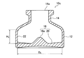
- the inside of the container includes a body portion that includes a bottom surface and a constant inner diameter, and the ratio between the height of the body portion and the diameter of the bottom surface inside the container is 1: 1 to 1: 5.
- a drug vial comprising the vial container according to any one of (1) to (10) and a drug filled in the vial container.
- the time required for dissolution / dilution of a drug is shortened, and the time until the foam disappears by suppressing the generation of bubbles during dissolution (defoaming time) is shortened.
- a vial container and a drug vial that can shorten the preparation time of the drug can be provided.
- FIG. 7 (A) is a cross-sectional view conceptually showing a drug vial using another example of the vial container of the present invention
- FIG. 7 (B) explains the action of the drug vial shown in FIG. 7 (A).
- FIG. 8 is a partial cross-sectional schematic perspective view conceptually showing another example of the drug vial of the present invention.
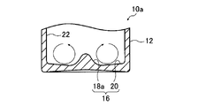
- FIG. 1 is a cross-sectional view schematically showing an embodiment of a vial container according to the present invention.
- the vial container 10a has a bottomed cylindrical barrel portion 12 and a mouth portion 14 connected to the opening surface side of the barrel portion 12 and having a diameter reduced toward the opening end portion 14a.
- a medicine such as a freeze-dried preparation (powder) or a liquid medicine is accommodated in the body part 12 and a stopper is attached to the mouth part 14 to seal the medicine in the vial container 10a.
- the shape of the mouth portion 14 is not particularly limited, and various known shapes can be used.
- the material of the vial container 10a is not particularly limited, and various known materials such as resin and glass conventionally used as the material of the vial container can be used.
- the inner bottom surface 16 (that is, the bottom surface inside the container) on the inner side of the barrel portion 12 is formed from the projection portion 18a formed at the center portion and from the inner peripheral surface 22 of the barrel portion 12 to the projection portion 18a. And an inclined surface 20 that is inclined so as to become lower.
- the protrusion 18a has a substantially conical shape with a rounded top.
- the diameter Dc of the bottom surface of the protrusion 18a is 5 to 95% of the diameter Db of the inner bottom surface 16.
- the diameter Dc of the bottom surface of the protrusion 18a is the diameter at the position where the height of the inner bottom surface 16 is the lowest.
- the inclined surface 20 is a surface inclined so as to become lower from the inner peripheral surface 22 of the body portion 12 toward the projection portion 18a, that is, in a direction away from the opening end portion 14a.
- the inclined surface 20 is a mortar-shaped surface.
- the vial container 10a of the present invention is formed such that the bottom surface inside the container has a protrusion 18a formed at the center.
- the protrusion 18a is present at the position that becomes the center of the vortex, so that the liquid is retained.
- the drug and the solution / diluent can be stirred uniformly, improving the solubility and shortening the dissolution time.
- the stirring property is improved, it is not necessary to shake the container vigorously during stirring, and the generation of bubbles can be suppressed and the defoaming time can be shortened. Therefore, the dissolution time and the defoaming time can be shortened to shorten the drug preparation time.
- the vial container 10a shown in FIG. 1 is such that the bottom surface inside the container is lowered toward the protruding portion 18a from the protruding portion 18a formed at the central portion and the inner peripheral surface 22 of the body portion 12. And an inclined surface 20 inclined to the surface.
- the drug and the solution / diluent are stirred using the vial container 10a having the inner bottom surface 16 having such a shape, not only the flow along the circumferential direction of the vial container 10a (body portion 12) but also FIG. A flow rotating around the circumferential direction as shown in FIG. 1, that is, a vertical flow and a radial flow are generated.
- the ratio of the diameter Dc of the bottom surface of the protrusion 18a to the diameter Db of the inner bottom surface 16 is 5 to 95%, preferably 5 to 70%, and more preferably 10 to 40%.
- the shape of the protrusion is not limited to the conical shape, and for example, the cross section parallel to the height direction may be a waveform such as a sine wave, or may be a triangular pyramid shape or the like.
- the shape of the cross section perpendicular to the height direction is not limited to a circular shape, and may be an elliptical shape, a polygonal shape, a cross shape, a star-shaped polygonal shape, or the like.
- it is preferable that the side surface of the protrusion is formed in a straight line when viewed in a cross section parallel to the height direction (a cross section parallel to the axial direction of the protrusion).
- the projection part By making the projection part have a linear shape on the side surface, the space between the peripheral surface inside the container and the side surface of the projection part can be widened, and stirring can be facilitated.
- the shape of the protrusion is preferably a conical shape or a truncated cone shape.
- FIG. 3A to FIG. 3C are partial cross-sectional schematic perspective views conceptually showing another example of the vial container of the present invention.
- Each of the vial containers shown in FIGS. 3A to 3C has the same configuration as the vial container 10a shown in FIG. 1 except that the shape of the protrusion is different. In the following description, different parts are mainly performed.
- the inner bottom surface 16 of the vial container 10f shown in FIG. 3A has a protruding portion 18c and an inclined surface 20.
- the protrusion 18c shown in the figure has a conical shape, and has four grooves on its side surface extending in a direction parallel to the height direction.
- the solution / diluent can be transferred to the groove and injected.
- the generation of bubbles when the solution / diluent is injected can be stably suppressed, and the defoaming time can be shortened.
- the inner bottom surface 16 of the vial container 10g shown in FIG. 3B has a protrusion 18d and an inclined surface 20.
- the protrusion 18d has a conical shape whose cross section perpendicular to the height direction is a star-shaped polygon (four-pointed star shape), and a shape that is substantially halved in a cross section parallel to the height direction.
- the cross section has a groove extending in a direction parallel to the height direction, that is, a groove passing through the center of the star-shaped polygon having a cross section perpendicular to the height direction. In other words, it has a shape in which a star-shaped polygon having a hole in the center is substantially halved in a cross section parallel to the height direction.
- the shape of the protrusion is substantially half of the cross section parallel to the height direction, when the drug and the solution / diluent are stirred, the portion where the liquid stays is eliminated, The drug and the solution / diluent can be stirred uniformly, so that the solubility can be improved and the dissolution time can be shortened.
- a groove may be provided in the cross section, and this groove is formed when the solution / dilution liquid is put into the container. The solution / diluent can be injected into the groove by applying the needle tip of the syringe containing the solution / diluent.
- the inner bottom surface 16 of the vial container 10 h shown in FIG. 3C has a protrusion 18 e and an inclined surface 20.
- the protrusion 18e includes a conical column and a substantially ellipsoidal umbrella provided at the top of the column. Moreover, the magnitude
- the vial adapter is used to connect the vial container and the syringe when the solution / diluent is injected into the vial container, and is attached to the mouth of the vial container.
- An adapter that holds the tube tip (needle) toward the inside of the vial container.
- the height Hc of the protrusion 18a is preferably a ratio of 5 to 60% with respect to the height Hb inside the trunk portion 12 (“the height inside the container” in the present invention). % Is more preferable.
- the inclined surface 20 has a linear shape when viewed in a cross section parallel to the height direction, but is not limited thereto, and may have a curved shape.
- the inclination angle ⁇ of the inclined surface 20 (inclination angle with respect to a plane including the edge where the inner peripheral surface 22 and the inclined surface 20 intersect) is preferably 0.5 to 15 degrees, and preferably 0.5 to 10 degrees. Is more preferable, and 0.5 to 5 degrees is particularly preferable.
- FIG. 4 is a sectional view conceptually showing another example of the vial container of the present invention.
- the vial container 10b shown in FIG. 4 has the same configuration as that of the vial container 10a shown in FIG. 1 except that R of a predetermined size is formed at the corner inside the container. In the following description, different parts are mainly described.
- the connecting portion between the inner peripheral surface 22 of the body portion 12 and the inclined surface 20, and the connecting portion between the inclined surface 20 and the protruding portion 18a are chamfered.
- the R size R1 of the connecting portion between the inner peripheral surface 22 and the inclined surface 20 is preferably 0.1 mm or more, more preferably 0.5 mm or more, and 1 mm or more. Particularly preferred.
- the R size R2 of the connecting portion between the inclined surface 20 and the protrusion 18a is preferably 0.1 mm or more, more preferably 0.5 mm or more, and particularly preferably 1 mm or more. .
- R1 and R2 By setting R1 and R2 to be 0.1 mm or more, particularly 1 mm or more, the drug is less likely to remain in the corners inside the container, which is preferable because the stirring ability is further improved. From the viewpoint of increasing the capacity of the container, it is preferable that R1 is 3 mm or less and R2 is 5 mm or less.
- drum 12 is larger than the height Hb inside the trunk
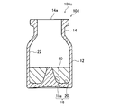
- FIG. 6 is a cross-sectional view showing an example of a preferred embodiment of a drug vial using the vial container according to the present invention.
- a drug vial 100a shown in FIG. 6 is one in which a drug 30 is accommodated in the barrel 12 of the vial container 10d.
- a stopper is attached to the mouth portion 14 of the vial container 10d to seal the medicine in the vial container 10a.
- the vial container 10d has the same configuration as the vial container 10a shown in FIG. 1 except that the height of the protrusion 18a is different. Mainly done.
- the protrusion 18a of the vial container 10d has a height protruding from the surface (upper surface) of the medicine 30 accommodated in the container.
- the generation of bubbles has been suppressed by injecting the solution with the needle tip of the syringe applied to the inner peripheral surface of the vial container.
- the needle tip in order to apply the needle tip to the inner peripheral surface of the container, it is necessary to bend the needle, which is difficult to carry out, and the needle may break, which is dangerous.
- the solution / diluent can be easily and safely transferred to the protrusion 18a and injected. Can do.
- FIG. 7 (A) is a cross-sectional view conceptually showing a drug vial using another example of the vial container of the present invention
- FIG. 7 (B) explains the action of the drug vial shown in FIG. 7 (A). It is a schematic sectional drawing for doing.
- a medicine vial 100b shown in FIG. 7A includes a vial container 10e, a medicine accommodated in the body part 12 of the vial container 10e, and a plug (not shown) attached to the mouth part 14 of the vial container 10e.
- the vial container 10e has the same configuration as that of the vial container 10a shown in FIG. 1 except that the shape of the protrusion is different. Therefore, the same parts are denoted by the same reference numerals, and the following description mainly focuses on the different parts. Do.
- the inner bottom surface 16 of the barrel 12 of the vial container 10e is formed to have a projection 18b formed at the center and an inclined surface 20 that is inclined so as to become lower from the inner peripheral surface 22 toward the projection 18b.
- the protrusion 18b has a truncated cone shape with a flat top.
- the protrusion 18a of the vial container 10d has a height protruding from the surface (upper surface) of the medicine 30 accommodated in the container, but the present invention is not limited to this.
- the height of the protrusion may be equal to or less than the height of the surface of the drug, that is, the height of the protrusion may be lower than or the same as the height of the surface of the drug.
- the tip of the protrusion 18a of the vial container 10d and the surface of the medicine 30 may be flush with each other.
- the height of the protrusion is set to be equal to or less than the height of the surface of the drug, it is possible to suppress the needle tip of the syringe from unintentionally hitting the protrusion when the solution / diluent is put into the container. .
- Example 1 As Example 1, the dissolution time of the drug was measured using the vial container 10a shown in FIG.
- the vial container 10a had a height (body height) Hb of 23 mm, and the inner bottom surface 16 had a diameter Db of 23 mm. Further, the bottom diameter Dc of the protrusion 18a was 7 mm, and the height Hc was 3 mm.
- the inclination angle ⁇ of the inclined surface 20 was 5 degrees.
- a protein preparation simulant sucrose, L-histidine hydrochloride, L-histidine, polysorbate 20
- a solution 1.5 mL of distilled water was used.
- the drug is contained in the vial container 10a, the solution is injected, and stirring is performed at 100 rpm using a shaker (BioShaker V • BR-36 manufactured by Taitec Co., Ltd.) to dissolve the time until the drug is homogenized. Measured as time. Judgment of solubility was made visually every other minute. As a result of measuring the dissolution time three times, the average value of the dissolution time was 12 minutes.
- Example 2 The dissolution time was measured in the same manner as in Example 1 except that the inclination angle ⁇ of the inclined surface 20 was 0 degree, that is, the structure without the inclined surface. As a result of the measurement, the average value of dissolution time was 13 minutes.
- Example 3 The dissolution time was measured in the same manner as in Example 1 except that the inclination angle ⁇ of the inclined surface 20 was ⁇ 5 degrees, that is, the inclined surface 20 was inclined so as to decrease toward the inner peripheral surface. As a result of the measurement, the average dissolution time was 15 minutes.
- Example 4 It is dissolved in the same manner as in Example 1 except that the R size R1 of the connecting portion between the inner peripheral surface and the inclined surface is 1 mm, and the R size R2 of the connecting portion between the inclined surface and the protruding portion is 3 mm. Time was measured. As a result of the measurement, the average value of dissolution time was 11 minutes.
- Comparative Example 1 As Comparative Example 1, dissolution time was measured in the same manner as in Example 1 using a vial container having the same shape as in Example 1 except that the inner bottom surface of the container was flat. As a result of the measurement, the average dissolution time was 22 minutes.
- the inner bottom surface of the container has a protrusion formed at the center, and an inclined surface that inclines so as to decrease from the side surface inside the container toward the protrusion, and the protrusion with respect to the diameter of the bottom surface Example 1 which is a vial container of the present invention configured to have a length ratio of the bottom side of 5 to 95% has a shorter dissolution time and a drug preparation time than Comparative Example 1 having a flat inner bottom surface. Can be shortened.
- the bottom surface inside the container has a protruding portion and an inclined surface that is inclined so as to become lower from the inner peripheral surface of the container toward the protruding portion.
- the connecting portion between the inner peripheral surface and the inclined surface and the connecting portion between the inclined surface and the protruding portion are preferably R-chamfered.
Landscapes
- Engineering & Computer Science (AREA)
- Health & Medical Sciences (AREA)
- Ceramic Engineering (AREA)
- Mechanical Engineering (AREA)
- General Health & Medical Sciences (AREA)
- Pharmacology & Pharmacy (AREA)
- Life Sciences & Earth Sciences (AREA)
- Animal Behavior & Ethology (AREA)
- Hematology (AREA)
- Public Health (AREA)
- Veterinary Medicine (AREA)
- Chemical & Material Sciences (AREA)
- Chemical Kinetics & Catalysis (AREA)
- Medical Preparation Storing Or Oral Administration Devices (AREA)
- Containers Having Bodies Formed In One Piece (AREA)
- Details Of Rigid Or Semi-Rigid Containers (AREA)
Abstract
薬剤の溶解/希釈にかかる時間を短縮し、また、溶解時の泡の発生を抑制して泡が消失するまでの時間を短縮して、薬剤の調製時間を短縮することができるバイアル容器および薬剤バイアルを提供する。容器内部の底面が、中央部に形成された突起部を有し、容器内部の底面の直径に対する突起部の底面の直径の比率が、5~95%である、ことにより上記課題を解決する。
Description
本発明は、薬剤を収容するバイアル容器および薬剤バイアルに関するものである。
従来、薬液を凍結乾燥させた凍結乾燥製剤等の粉剤や液剤をバイアル容器内に密封した薬剤バイアルが使用されている(例えば、特許文献1)。このような薬剤バイアルを使用する際には、バイアル容器内に溶解液あるいは希釈液を注入して、薬剤を溶解または希釈し、溶解/希釈した薬液をシリンジ中に吸い取り、人体への注射等に使用する。
ところで、バイアル容器に収容された溶解性の低い粉剤や、粘度の高い液剤を溶解または希釈する場合に、薬剤を均一に溶解するために調製に長い時間を要し、治療時間の短縮の妨げの要因となっているという問題があった。
例えば、薬剤を溶解/希釈する場合には、溶解液または希釈液をバイアル容器内に注入後、円を描くように容器を振って撹拌する。この時、容器内部の底面中央付近は渦の中心部となるため、液の流れが生じにくい。そのため、容器内の中央付近の薬剤が溶け難く、溶け残ってしまったり、均一に混ざりにくくなるため、溶解時間が長くなってしまう。
ここで、溶解液を注入後、撹拌する際に、容器を振って撹拌することにより、溶解時間を短縮することができる。しかしながら、容器を振って撹拌すると泡が発生してしまうため、撹拌後、泡が消失するまで待つ必要があるため、やはり、治療時間の短縮の妨げとなる。また、バイアル内の薬剤が溶解時に泡が発生しやすい薬剤の場合にも、溶解液/希釈液を注入する際に泡が発生して、泡が消失するまでの時間が必要となり、やはり、治療時間の短縮の妨げとなる。
本発明の目的は、上記従来技術の問題点を解消し、薬剤の溶解/希釈にかかる時間(溶解時間)を短縮し、また、溶解時の泡の発生を抑制して泡が消失するまでの時間(消泡時間)を短縮して、薬剤の調製時間を短縮することができるバイアル容器および薬剤バイアルを提供することにある。
なお、本発明において、薬剤調製時間を薬剤の溶解時間と消泡時間の和と定義する。
なお、本発明において、薬剤調製時間を薬剤の溶解時間と消泡時間の和と定義する。
本発明者らは、上記課題を達成すべく鋭意研究した結果、容器内部の底面が、中央部に形成された突起部を有し、底面の直径に対する突起部の底辺の長さの比率が、5~95%である構成とすることによって、溶解時間および消泡時間を短縮して薬剤調製時間を短縮することが可能となることを見出し、本発明を完成させた。
すなわち、本発明は、以下の構成のバイアル容器および薬剤バイアルを提供する。
すなわち、本発明は、以下の構成のバイアル容器および薬剤バイアルを提供する。
(1) 薬剤を収容する有底筒状のバイアル容器であって、容器内部の底面が、中央部に形成された突起部を有し、底面の直径に対する突起部の底辺の長さの比率が、5~95%であるバイアル容器。
(2) 突起部の側面の一部は、軸に平行な断面において、直線状に形成される(1)に記載のバイアル容器。
(3) 突起部は、略円錐形状である(1)または(2)に記載のバイアル容器。
(4) 突起部が円錐台形状である(1)または(2)に記載のバイアル容器。
(5) 容器内部の底面は、突起部と、容器内部の周面から突起部に向かって低くなるように傾斜する傾斜面とを有してなる(1)~(4)のいずれかに記載のバイアル容器。
(6) 容器内部の周面と傾斜面とが交わる端辺を含む平面に対する傾斜面の傾斜角度が、0.5~15度である(5)に記載のバイアル容器。
(7) 周面と傾斜面との接続部がR面取形状であり、Rの大きさが0.1~3mmである(5)また(6)に記載のバイアル容器。
(8) 傾斜面と突起部との接続部がR面取形状であり、Rの大きさが0.1~5mmである(5)~(7)のいずれかに記載のバイアル容器。
(3) 突起部は、略円錐形状である(1)または(2)に記載のバイアル容器。
(4) 突起部が円錐台形状である(1)または(2)に記載のバイアル容器。
(5) 容器内部の底面は、突起部と、容器内部の周面から突起部に向かって低くなるように傾斜する傾斜面とを有してなる(1)~(4)のいずれかに記載のバイアル容器。
(6) 容器内部の周面と傾斜面とが交わる端辺を含む平面に対する傾斜面の傾斜角度が、0.5~15度である(5)に記載のバイアル容器。
(7) 周面と傾斜面との接続部がR面取形状であり、Rの大きさが0.1~3mmである(5)また(6)に記載のバイアル容器。
(8) 傾斜面と突起部との接続部がR面取形状であり、Rの大きさが0.1~5mmである(5)~(7)のいずれかに記載のバイアル容器。
(9) 容器内部は、底面を含み、内径が一定の領域である胴部を有してなり、胴部の高さと容器内部の底面の直径との比率が1:1~1:5である(1)~(8)のいずれかに記載のバイアル容器。
(10) 突起部の高さが、容器内部の高さの5%~60%である(1)~(9)のいずれかに記載のバイアル容器。
(10) 突起部の高さが、容器内部の高さの5%~60%である(1)~(9)のいずれかに記載のバイアル容器。
(11) (1)~(10)のいずれかに記載のバイアル容器と、バイアル容器内に充填された薬剤と、を有する薬剤バイアル。
(12) 突起部の高さが、容器内に充填された薬剤の表面の高さよりも高い(11)に記載の薬剤バイアル。
(12) 突起部の高さが、容器内に充填された薬剤の表面の高さよりも高い(11)に記載の薬剤バイアル。
本発明によれば、薬剤の溶解/希釈にかかる時間(溶解時間)を短縮し、また、溶解時の泡の発生を抑制して泡が消失するまでの時間(消泡時間)を短縮して、薬剤の調製時間を短縮することができるバイアル容器および薬剤バイアルを提供することができる。
本発明に係るバイアル容器を、添付の図面に示す好適実施形態に基づいて以下に詳細に説明する。
図1は、本発明に係るバイアル容器の一実施形態の概略を示す断面図である。
図1は、本発明に係るバイアル容器の一実施形態の概略を示す断面図である。
図1に示すように、バイアル容器10aは、有底円筒状の胴部12と、胴部12の開口面側に接続され、開口端部14aに向かって縮径する口部14とを有し、胴部12内に凍結乾燥製剤(粉剤)や液剤などの薬剤を収容し、口部14に栓体が取り付けられて、薬剤をバイアル容器10a内に密封するものである。
本発明において、口部14の形状には特に限定はなく、種々の公知の形状が利用可能である。また、バイアル容器10aの材質にも特に限定はなく、従来、バイアル容器の材料として用いられている樹脂、ガラス等の種々の公知の材料が利用可能である。また、胴部12や口部14の肉厚にも特に限定はない。
本発明のバイアル容器10aにおいて、胴部12内側の内底面16(すなわち、容器内部の底面)は、中央部に形成された突起部18aと、胴部12の内周面22から突起部18aに向かって低くなるように傾斜した傾斜面20とを有して形成される。
図示例において、突起部18aは、頂部が丸められた略円錐形状である。
ここで、突起部18aの底面の直径Dcは、内底面16の直径Dbに対して5~95%の比率である。
なお、本発明において、突起部18aの底面の直径Dcは、内底面16の高さが最も低くなる位置での直径である。
ここで、突起部18aの底面の直径Dcは、内底面16の直径Dbに対して5~95%の比率である。
なお、本発明において、突起部18aの底面の直径Dcは、内底面16の高さが最も低くなる位置での直径である。
一方、傾斜面20は、胴部12の内周面22から突起部18aに向かって低くなるように、すなわち、開口端部14aから遠くなる方向に傾斜した面である。言い換えると、傾斜面20は、すり鉢状の面である。
前述のとおり、従来、溶解性の低い粉剤や粘度の高い液剤等の薬剤が収容されたバイアル容器に、溶解液または希釈液を注入して、薬剤を溶解または希釈する場合に、容器を振って撹拌しても、容器内部の底面中央付近は渦の中心部となり、液の流れが生じにくいため、容器内の中央付近の薬剤が溶け難く、薬剤を均一に溶解/希釈するための溶解時間が長くなってしまい、治療時間の短縮の妨げとなるという問題があった。
また、溶解時間を短縮するために、容器を激しく振って撹拌すると、泡が発生してしまうため、泡が消失するまで待つ必要があり、やはり、治療時間の短縮の妨げとなるという問題があった。
また、溶解時間を短縮するために、容器を激しく振って撹拌すると、泡が発生してしまうため、泡が消失するまで待つ必要があり、やはり、治療時間の短縮の妨げとなるという問題があった。
これに対して、本発明のバイアル容器10aは、容器内部の底面が、中央部に形成された突起部18aを有して形成される。このような形状の内底面16を有するバイアル容器10aを用いて、薬剤と溶解液/希釈液とを撹拌すると、渦の中心部となる位置に突起部18aが存在するので、液が滞留する部分をなくして、薬剤と溶解液/希釈液とを均一に撹拌することができ、溶解性が向上して溶解時間を短縮することができる。また、撹拌性が向上するので、撹拌の際に容器を激しく振る必要がなく、泡の発生を抑制して、消泡時間を短縮することができる。従って、溶解時間および消泡時間を短縮して薬剤調製時間を短縮することができる。
また、図1に示すバイアル容器10aは、好ましい態様として、容器内部の底面が、中央部に形成された突起部18aと、胴部12の内周面22から突起部18aに向かって低くなるように傾斜した傾斜面20とを有して形成される。このような形状の内底面16を有するバイアル容器10aを用いて、薬剤と溶解液/希釈液とを撹拌すると、バイアル容器10a(胴部12)の周方向に沿った流れのみならず、図2に示すような円周方向を軸として回転する流れ、すなわち、上下方向および半径方向の流れが生じる。底面の傾斜があることにより、中心方向のより大きな流れが発生し撹拌性が向上して、薬剤を均一に溶解でき、溶解性が向上して溶解時間を短縮することができる。また、撹拌性が向上するので、撹拌の際に容器を激しく振る必要がなく、泡の発生を抑制して、消泡時間を短縮することができる。従って、溶解時間および消泡時間を短縮して薬剤調製時間を短縮することができる。
ここで、内底面16の直径Dbに対する突起部18aの底面の直径Dcの比率は、5~95%であり、5~70%であることが好ましく、10~40%であることがより好ましい。
内底面16の直径Dbに対する突起部18aの底面の直径Dcの比率をこの範囲とすることにより、液が滞留する部分をより好適になくすことができ、溶解時間をより好適に短縮することができる。
内底面16の直径Dbに対する突起部18aの底面の直径Dcの比率をこの範囲とすることにより、液が滞留する部分をより好適になくすことができ、溶解時間をより好適に短縮することができる。
また、突起部の形状は、円錐形状に限定はされず、例えば、高さ方向に平行な断面が正弦波等の波形のものであってもよく、あるいは、三角錐形状等であってもよく、また、高さ方向に垂直な断面の形状も円形状に限定はされず、楕円形状、多角形状、十字形状、星型多角形状等であってもよい。
なお、突起部は、高さ方向に平行な断面(突起部の軸方向に平行な断面)で見た際に、その側面が直線状に形成されるのが好ましい。突起部をその側面が直線状の形状とすることにより、容器内部の周面と突起部の側面との間の空間を広くすることができ、撹拌しやすくすることができる。具体的には、突起部の形状は、円錐形状、円錐台形状であるのが好ましい。
なお、突起部は、高さ方向に平行な断面(突起部の軸方向に平行な断面)で見た際に、その側面が直線状に形成されるのが好ましい。突起部をその側面が直線状の形状とすることにより、容器内部の周面と突起部の側面との間の空間を広くすることができ、撹拌しやすくすることができる。具体的には、突起部の形状は、円錐形状、円錐台形状であるのが好ましい。
図3(A)~図3(C)を用いて、突起部の他の形状について説明する。
図3(A)~図3(C)はそれぞれ、本発明のバイアル容器の他の一例を概念的に示す一部断面概略斜視図である。
なお、図3(A)~図3(C)に示すバイアル容器はそれぞれ、突起部の形状が異なる以外は図1に示すバイアル容器10aと同様の構成を有するので、同じ部位には同じ符号を付し、以下の説明では異なる部位を主に行う。
図3(A)~図3(C)はそれぞれ、本発明のバイアル容器の他の一例を概念的に示す一部断面概略斜視図である。
なお、図3(A)~図3(C)に示すバイアル容器はそれぞれ、突起部の形状が異なる以外は図1に示すバイアル容器10aと同様の構成を有するので、同じ部位には同じ符号を付し、以下の説明では異なる部位を主に行う。
図3(A)に示すバイアル容器10fの内底面16は、突起部18cと傾斜面20とを有する。
図に示す突起部18cは、円錐形状であり、その側面に、高さ方向に平行な方向に延在する溝を4つ有するものである。このように、突起部が少なくとも1つの溝を有する形状とすることで、容器内に溶解液/希釈液を入れる際に、突起部18cの溝に、溶解液/希釈液が入ったシリンジの針先を当てて溶解液/希釈液を溝に伝わらせて注入することができる。溶解液/希釈液を溝に伝わらせて注入することで、溶解液/希釈液を注入する際の泡の発生を安定して抑制することができ、消泡時間を短縮することができる。
図に示す突起部18cは、円錐形状であり、その側面に、高さ方向に平行な方向に延在する溝を4つ有するものである。このように、突起部が少なくとも1つの溝を有する形状とすることで、容器内に溶解液/希釈液を入れる際に、突起部18cの溝に、溶解液/希釈液が入ったシリンジの針先を当てて溶解液/希釈液を溝に伝わらせて注入することができる。溶解液/希釈液を溝に伝わらせて注入することで、溶解液/希釈液を注入する際の泡の発生を安定して抑制することができ、消泡時間を短縮することができる。
図3(B)に示すバイアル容器10gの内底面16は、突起部18dと傾斜面20とを有する。
突起部18dは、高さ方向に垂直な断面の形状が、星型多角形(四芒星形状)である錐型で、かつ、高さ方向に平行な断面で略半分にした形状を有する。また、断面には、高さ方向に平行な方向に延在する溝、すなわち、高さ方向に垂直な断面の星型多角形における中心を通る溝を有する。言い換えると、中心に穴を有する星型多角形を高さ方向に平行な断面で略半分にした形状を有する。
突起部18dは、高さ方向に垂直な断面の形状が、星型多角形(四芒星形状)である錐型で、かつ、高さ方向に平行な断面で略半分にした形状を有する。また、断面には、高さ方向に平行な方向に延在する溝、すなわち、高さ方向に垂直な断面の星型多角形における中心を通る溝を有する。言い換えると、中心に穴を有する星型多角形を高さ方向に平行な断面で略半分にした形状を有する。
このように、突起部の形状を高さ方向に平行な断面で略半分にした形状とした場合でも、薬剤と溶解液/希釈液とを撹拌する際に、液が滞留する部分をなくして、薬剤と溶解液/希釈液とを均一に撹拌することができ、溶解性が向上して溶解時間を短縮することができる。
また、突起部の形状を高さ方向に平行な断面で略半分にした形状とした場合には、断面に溝を設けてもよく、容器内に溶解液/希釈液を入れる際に、この溝に、溶解液/希釈液が入ったシリンジの針先を当てて溶解液/希釈液を溝に伝わらせて注入することができる。
また、突起部の形状を高さ方向に平行な断面で略半分にした形状とした場合には、断面に溝を設けてもよく、容器内に溶解液/希釈液を入れる際に、この溝に、溶解液/希釈液が入ったシリンジの針先を当てて溶解液/希釈液を溝に伝わらせて注入することができる。
図3(C)に示すバイアル容器10hの内底面16は、突起部18eと傾斜面20とを有する。
突起部18eは、円錐形状の柱部と、柱部の頂部に設けられる、略楕円体形状の傘部とを有して構成される。また、高さ方向から見た際の、傘部の大きさは、柱部の頂部の大きさよりも大きい。すなわち、突起部18eは、いわゆる、きのこ型の形状を有する。
突起部18eは、円錐形状の柱部と、柱部の頂部に設けられる、略楕円体形状の傘部とを有して構成される。また、高さ方向から見た際の、傘部の大きさは、柱部の頂部の大きさよりも大きい。すなわち、突起部18eは、いわゆる、きのこ型の形状を有する。
このように、突起部の形状をきのこ型とすることで、容器内に溶解液/希釈液を入れる際に、針先を突起部に当てずに注入した場合や、バイアルアダプターを使用する場合に、溶解液/希釈液が傘部に当たり、薬剤に直接当たらないため、空気を巻き込んで生じる泡立ちを抑制でき、消泡時間を短縮することができる。言い換えると、溶解液/希釈液の注入の際に、泡立ちを抑制するために、針先を突起部や内周面に当てる必要がないので、作業性が向上する。
なお、バイアルアダプターとは、溶解液/希釈液をバイアル容器内に注入する際に、バイアル容器とシリンジとを連結するものであり、バイアル容器の口部に取り付けられ、かつ、シリンジを、シリンジの筒先(針)をバイアル容器内に向けて保持するアダプターである。
なお、バイアルアダプターとは、溶解液/希釈液をバイアル容器内に注入する際に、バイアル容器とシリンジとを連結するものであり、バイアル容器の口部に取り付けられ、かつ、シリンジを、シリンジの筒先(針)をバイアル容器内に向けて保持するアダプターである。
また、突起部18aの高さHcは、胴部12内側の高さHb(本発明における「容器内部の高さ」)に対して、5~60%の比率であることが好ましく、10~35%であることがより好ましい。
容器内部の高さHbに対する突起部18aの高さHcの比率を上記範囲とすることにより、液が滞留する部分をより好適になくすことができ、また、円周方向を軸として回転する流れをより好適に発生させることができ、溶解時間をより好適に短縮することができる。
容器内部の高さHbに対する突起部18aの高さHcの比率を上記範囲とすることにより、液が滞留する部分をより好適になくすことができ、また、円周方向を軸として回転する流れをより好適に発生させることができ、溶解時間をより好適に短縮することができる。
また、図示例では、傾斜面20は、高さ方向に平行な断面で見た際に、直線形状としたが、これに限定はされず、曲線形状であってもよい。
また、傾斜面20の傾斜角度θ(内周面22と傾斜面20とが交わる端辺を含む平面に対する傾斜角度)は、0.5~15度であることが好ましく、0.5~10度であることがより好ましく、0.5~5度であることが特に好ましい。
傾斜面20の傾斜角度θを上記範囲とすることにより、円周方向を軸として回転する流れをより好適に発生させることができ、溶解時間をより好適に短縮することができる。
傾斜面20の傾斜角度θを上記範囲とすることにより、円周方向を軸として回転する流れをより好適に発生させることができ、溶解時間をより好適に短縮することができる。
また、容器内部の角部は、R面取形状とするのが好ましく、Rの大きさを所定の範囲とするのが好ましい。
図4は、本発明のバイアル容器の他の一例を概念的に表す断面図である。
図4に示すバイアル容器10bは、容器内部の角部に所定の大きさのRを形成した以外は、図1に示すバイアル容器10aと同様の構成を有するので、同じ部位には同じ符号を付し、以下の説明は異なる部位を主に行う。
図4は、本発明のバイアル容器の他の一例を概念的に表す断面図である。
図4に示すバイアル容器10bは、容器内部の角部に所定の大きさのRを形成した以外は、図1に示すバイアル容器10aと同様の構成を有するので、同じ部位には同じ符号を付し、以下の説明は異なる部位を主に行う。
図4に示すように、バイアル容器10bは、胴部12の内周面22と傾斜面20との接続部、ならびに、傾斜面20と突起部18aとの接続部がR面取りされている。
ここで、内周面22と傾斜面20との接続部のRの大きさR1は、0.1mm以上とするのが好ましく、0.5mm以上とするのがより好ましく、1mm以上とするのが特に好ましい。また、傾斜面20と突起部18aとの接続部のRの大きさR2は、0.1mm以上とするのが好ましく、0.5mm以上とするのがより好ましく、1mm以上とするのが特に好ましい。
R1およびR2を0.1mm以上、特に1mm以上とすることにより、容器内部の角部に薬剤が残留しにくくなるため、撹拌性がさらに向上するので好ましい。
また、容器の容量を大きくする観点から、R1を3mm以下、R2を5mm以下とするのが好ましい。
ここで、内周面22と傾斜面20との接続部のRの大きさR1は、0.1mm以上とするのが好ましく、0.5mm以上とするのがより好ましく、1mm以上とするのが特に好ましい。また、傾斜面20と突起部18aとの接続部のRの大きさR2は、0.1mm以上とするのが好ましく、0.5mm以上とするのがより好ましく、1mm以上とするのが特に好ましい。
R1およびR2を0.1mm以上、特に1mm以上とすることにより、容器内部の角部に薬剤が残留しにくくなるため、撹拌性がさらに向上するので好ましい。
また、容器の容量を大きくする観点から、R1を3mm以下、R2を5mm以下とするのが好ましい。
また、図5に示すように、バイアル容器10cは、胴部12の内底面16の直径Dbが、胴部12内側の高さHbよりも大きいことが好ましい。
具体的には、胴部12内側の高さHbと内底面16の直径Dbとの比率が、Hb:Db=1:1~1:5であるのが好ましく、Hb:Db=1:1~1:3であるのがより好ましく、Hb:Db=1:1~1:1.5であるのが特に好ましい。
このように、容器内部の直径Dbを大きくすることにより、薬剤を溶解/希釈する際の撹拌時に、容器周方向における流速が速くなり撹拌性が向上する。
具体的には、胴部12内側の高さHbと内底面16の直径Dbとの比率が、Hb:Db=1:1~1:5であるのが好ましく、Hb:Db=1:1~1:3であるのがより好ましく、Hb:Db=1:1~1:1.5であるのが特に好ましい。
このように、容器内部の直径Dbを大きくすることにより、薬剤を溶解/希釈する際の撹拌時に、容器周方向における流速が速くなり撹拌性が向上する。
次に、上記のバイアル容器に薬剤を収容した薬剤バイアルの好適な実施形態について説明する。
図6は、本発明に係るバイアル容器を用いる薬剤バイアルの好適な実施形態の一例を示す断面図である。
図6は、本発明に係るバイアル容器を用いる薬剤バイアルの好適な実施形態の一例を示す断面図である。
図6に示す薬剤バイアル100aは、バイアル容器10dの胴部12内に薬剤30を収容したものである。なお、図示は省略するがバイアル容器10dの口部14には、栓体が取り付けられて、薬剤をバイアル容器10a内に密封する。
なお、バイアル容器10dは、突起部18aの高さが異なる以外は、図1に示すバイアル容器10aと同様の構成を有するので、同じ部位には同じ符号を付し、以下の説明は異なる部位を主に行う。
なお、バイアル容器10dは、突起部18aの高さが異なる以外は、図1に示すバイアル容器10aと同様の構成を有するので、同じ部位には同じ符号を付し、以下の説明は異なる部位を主に行う。
図6に示すように、薬剤バイアル100aにおいて、バイアル容器10dの突起部18aは、容器内に収容された薬剤30の表面(上面)から突出する高さである。
このように、バイアル容器10aの突起部18aの高さを薬剤30の表面よりも高くすることが好ましい。これにより、容器内に溶解液/希釈液を入れる際に、突起部18aの薬剤30表面から突出した位置に、溶解液/希釈液が入ったシリンジの針先を当てて溶解液/希釈液を突起部に伝わらせて注入することができる。従って、溶解液/希釈液を注入する際の泡の発生を抑制することができ、消泡時間を短縮することができる。
このように、バイアル容器10aの突起部18aの高さを薬剤30の表面よりも高くすることが好ましい。これにより、容器内に溶解液/希釈液を入れる際に、突起部18aの薬剤30表面から突出した位置に、溶解液/希釈液が入ったシリンジの針先を当てて溶解液/希釈液を突起部に伝わらせて注入することができる。従って、溶解液/希釈液を注入する際の泡の発生を抑制することができ、消泡時間を短縮することができる。
ここで、従来の薬剤バイアルにおいては、バイアル容器の内周面にシリンジの針先を当てて溶解液を注入することで、泡の発生を抑制することが行われていた。しかしながら、容器の内周面に針先を当てるために、針を撓ませる必要があり実施し難く、また、針が折れる恐れがあり危険であった。
これに対して、バイアル容器10dの中央部に薬剤の表面から突出する突起部18aを有することで、容易に、かつ、安全に、溶解液/希釈液を突起部18aに伝わらせて注入することができる。
また、図1に示すバイアル容器10aでは、突起部18aの形状を略円錐形状としたが、これに限定はされず、突起部の形状を円錐台形状としてもよい。
図7(A)は、本発明のバイアル容器の他の一例を用いる薬剤バイアルを概念的に示す断面図であり、図7(B)は、図7(A)に示す薬剤バイアルの作用を説明するための概略断面図である。
図7(A)は、本発明のバイアル容器の他の一例を用いる薬剤バイアルを概念的に示す断面図であり、図7(B)は、図7(A)に示す薬剤バイアルの作用を説明するための概略断面図である。
図7(A)に示す薬剤バイアル100bは、バイアル容器10eと、バイアル容器10eの胴部12内に収容された薬剤と、バイアル容器10eの口部14に取り付けられる栓体(図示せず)とを有する。
なお、バイアル容器10eは、突起部の形状が異なる以外は、図1に示すバイアル容器10aと同様の構成を有するので、同じ部位には同じ符号を付し、以下の説明は異なる部位を主に行う。
なお、バイアル容器10eは、突起部の形状が異なる以外は、図1に示すバイアル容器10aと同様の構成を有するので、同じ部位には同じ符号を付し、以下の説明は異なる部位を主に行う。
バイアル容器10eの胴部12の内底面16は、中央に形成された突起部18bと、内周面22から突起部18bに向かって低くなるように傾斜した傾斜面20とを有して形成される。
ここで、突起部18bは、頂部が平坦な円錐台形状である。
ここで、突起部18bは、頂部が平坦な円錐台形状である。
このような形状の突起部18bを有するバイアル容器10eを用いた薬剤バイアル100bの作用について、図7(B)を用いて説明を行う。
バイアル容器10e内に溶解液/希釈液を注入し、撹拌すると、突起部18bの裾に溶解液32の流れが当たることによって、中心部への溶解液32の滲入速度が低下する。また、中心部の流れは弱い。そのため、撹拌開始直後は、図7(B)に示すように、突起部18bの上の薬剤30が溶け残り、撹拌が進むにつれ、徐々に中心部の薬剤30が溶解される。
このように、薬剤を徐々に溶かすことにより、いわゆるダマになって溶け残ることを防止して均一に溶解することができ、また、泡の発生を抑制して、消泡時間を短縮することができる。
このように、薬剤を徐々に溶かすことにより、いわゆるダマになって溶け残ることを防止して均一に溶解することができ、また、泡の発生を抑制して、消泡時間を短縮することができる。
また、図6に示す薬剤バイアル100aでは、バイアル容器10dの突起部18aが、容器内に収容された薬剤30の表面(上面)から突出する高さを有する構成としたが、これに限定はされず、突起部の高さが薬剤の表面の高さ以下、すなわち、突起部の高さが薬剤の表面の高さよりも低い、または、同じであってもよい。
例えば、図8に示す薬剤バイアル100cのように、バイアル容器10dの突起部18aの先端部と、薬剤30の表面とは面一であってもよい。
このように、突起部の高さを薬剤の表面の高さ以下とすることで、容器内に溶解液/希釈液を入れる際に、シリンジの針先が意図せず突起部に当たることを抑制できる。
例えば、図8に示す薬剤バイアル100cのように、バイアル容器10dの突起部18aの先端部と、薬剤30の表面とは面一であってもよい。
このように、突起部の高さを薬剤の表面の高さ以下とすることで、容器内に溶解液/希釈液を入れる際に、シリンジの針先が意図せず突起部に当たることを抑制できる。
次に、本発明のバイアル容器について、実施例を用いて、より詳細に説明する。
[実施例1]
実施例1として、図1に示すバイアル容器10aを用いて薬剤の溶解時間を測定した。
バイアル容器10aの高さ(胴部の高さ)Hbは、23mmとし、内底面16の直径Dbは、23mmとした。
また、突起部18aの底面直径Dcは、7mmとし、高さHcは、3mmとした。
また、傾斜面20の傾斜角度θは、5度とした。
実施例1として、図1に示すバイアル容器10aを用いて薬剤の溶解時間を測定した。
バイアル容器10aの高さ(胴部の高さ)Hbは、23mmとし、内底面16の直径Dbは、23mmとした。
また、突起部18aの底面直径Dcは、7mmとし、高さHcは、3mmとした。
また、傾斜面20の傾斜角度θは、5度とした。
薬剤として、タンパク製剤模擬薬(白糖、L-ヒスチジン塩酸塩、L-ヒスチジン、ポリソルベート20)を150mg用いた。
溶解液として、蒸留水を1.5mL用いた。
溶解液として、蒸留水を1.5mL用いた。
バイアル容器10a内に、薬剤を収容し、溶解液を注入して振とう器(タイテック社製BioShaker V・BR-36)を用いて100rpmで撹拌を行い、薬剤が均一化するまでの時間を溶解時間として測定した。
溶解性の判定は目視で1分おきに行った。
溶解時間の測定を3回行った結果、溶解時間の平均値は12分であった。
溶解性の判定は目視で1分おきに行った。
溶解時間の測定を3回行った結果、溶解時間の平均値は12分であった。
[実施例2]
傾斜面20の傾斜角度θを0度、すなわち、傾斜面を有さない構成とした以外は実施例1と同様にして溶解時間の測定を行った。
測定の結果、溶解時間の平均値は13分であった。
傾斜面20の傾斜角度θを0度、すなわち、傾斜面を有さない構成とした以外は実施例1と同様にして溶解時間の測定を行った。
測定の結果、溶解時間の平均値は13分であった。
[実施例3]
傾斜面20の傾斜角度θを-5度、すなわち、内周面に向かって低くなるように傾斜する構成とした以外は実施例1と同様にして溶解時間の測定を行った。
測定の結果、溶解時間の平均値は15分であった。
傾斜面20の傾斜角度θを-5度、すなわち、内周面に向かって低くなるように傾斜する構成とした以外は実施例1と同様にして溶解時間の測定を行った。
測定の結果、溶解時間の平均値は15分であった。
[実施例4]
内周面と傾斜面との接続部のRの大きさR1を1mmとし、傾斜面と突起部との接続部のRの大きさR2を3mmとした以外は、実施例1と同様にして溶解時間の測定を行った。
測定の結果、溶解時間の平均値は11分であった。
内周面と傾斜面との接続部のRの大きさR1を1mmとし、傾斜面と突起部との接続部のRの大きさR2を3mmとした以外は、実施例1と同様にして溶解時間の測定を行った。
測定の結果、溶解時間の平均値は11分であった。
[比較例1]
比較例1として、容器の内底面が平坦である以外は、実施例1と同様の形状のバイアル容器を用いて、実施例1と同様に溶解時間の測定を行った。
測定の結果、溶解時間の平均値は22分であった。
比較例1として、容器の内底面が平坦である以外は、実施例1と同様の形状のバイアル容器を用いて、実施例1と同様に溶解時間の測定を行った。
測定の結果、溶解時間の平均値は22分であった。
以上の結果から、容器の内底面を、中央部に形成された突起部と、容器内部の側面から突起部に向かって低くなるように傾斜する傾斜面とを有し、底面の直径に対する突起部の底辺の長さの比率が、5~95%である構成とした本発明のバイアル容器である実施例1は、平坦な内底面を有する比較例1に比べて溶解時間が短く、薬剤調製時間を短縮できることがわかる。
また、実施例1~3の対比から、容器内部の底面は、突起部と、容器の内周面から突起部に向かって低くなるように傾斜する傾斜面とを有してなることが好ましいことがわかる。
また、実施例1、4の対比から、内周面と傾斜面との接続部、および、傾斜面と突起部との接続部をR面取形状とするのが好ましいことがわかる。
また、実施例1、4の対比から、内周面と傾斜面との接続部、および、傾斜面と突起部との接続部をR面取形状とするのが好ましいことがわかる。
以上、本発明のバイアル容器および薬剤バイアルについて詳細に説明したが、本発明は、上記実施形態に限定されるものではなく、本発明の要旨を逸脱しない範囲において、各種の改良や変更を行ってもよい。
10 バイアル容器
12 胴部
14 口部
14a 開口端部
16 内底面
18 突起部
20 傾斜面
22 内周面
30 薬剤
32 溶解液
100 薬剤バイアル
12 胴部
14 口部
14a 開口端部
16 内底面
18 突起部
20 傾斜面
22 内周面
30 薬剤
32 溶解液
100 薬剤バイアル
Claims (9)
- 薬剤を収容する有底筒状のバイアル容器であって、
容器内部の底面が、中央部に形成された突起部を有し、
前記容器内部の底面の直径に対する前記突起部の底面の直径の比率が、5~95%であることを特徴とするバイアル容器。 - 前記突起部の側面の一部は、軸に平行な断面において、直線状に形成される請求項1に記載のバイアル容器。
- 前記突起部は、略円錐形状である請求項1または2に記載のバイアル容器。
- 前記突起部が円錐台形状である請求項1または2に記載のバイアル容器。
- 前記容器内部の底面は、前記突起部と、前記容器内部の周面から前記突起部に向かって低くなるように傾斜する傾斜面とを有してなる請求項1~4のいずれか1項に記載のバイアル容器。
- 前記周面と前記傾斜面との接続部がR面取形状であり、Rの大きさが0.1~3mmである請求項5に記載のバイアル容器。
- 前記傾斜面と前記突起部との接続部がR面取形状であり、Rの大きさが0.1~5mmである請求項5または6に記載のバイアル容器。
- 前記容器内部は、底面を含み、内径が一定の領域である胴部を有してなり、
前記胴部の高さと前記容器内部の底面の直径との比率が、1:1~1:5である請求項1~7のいずれか1項に記載のバイアル容器。 - 請求項1~8のいずれか1項に記載のバイアル容器と、
前記バイアル容器内に充填された薬剤と、を有する薬剤バイアル。
Priority Applications (1)
| Application Number | Priority Date | Filing Date | Title |
|---|---|---|---|
| JP2015557798A JP6425665B2 (ja) | 2014-01-17 | 2015-01-07 | バイアル容器および薬剤バイアル |
Applications Claiming Priority (2)
| Application Number | Priority Date | Filing Date | Title |
|---|---|---|---|
| JP2014007174 | 2014-01-17 | ||
| JP2014-007174 | 2014-01-17 |
Publications (1)
| Publication Number | Publication Date |
|---|---|
| WO2015107953A1 true WO2015107953A1 (ja) | 2015-07-23 |
Family
ID=53542843
Family Applications (1)
| Application Number | Title | Priority Date | Filing Date |
|---|---|---|---|
| PCT/JP2015/050239 Ceased WO2015107953A1 (ja) | 2014-01-17 | 2015-01-07 | バイアル容器および薬剤バイアル |
Country Status (2)
| Country | Link |
|---|---|
| JP (1) | JP6425665B2 (ja) |
| WO (1) | WO2015107953A1 (ja) |
Cited By (1)
| Publication number | Priority date | Publication date | Assignee | Title |
|---|---|---|---|---|
| EP3789114A1 (en) * | 2019-09-04 | 2021-03-10 | SCHOTT Schweiz AG | Dead end container and container assembly with dead end container |
Citations (4)
| Publication number | Priority date | Publication date | Assignee | Title |
|---|---|---|---|---|
| JP2000062786A (ja) * | 1998-08-21 | 2000-02-29 | Shinichi Sato | 円錐底容器 |
| JP2007204120A (ja) * | 2006-02-02 | 2007-08-16 | Mitsubishi Chemical Engineering Corp | 沈降性スラリーの容器 |
| JP2009208832A (ja) * | 2008-03-06 | 2009-09-17 | Shojiro Harato | 攪拌機能を有した容器 |
| JP3183090U (ja) * | 2013-02-12 | 2013-04-25 | 大塚テクノ株式会社 | 振とう装置 |
Family Cites Families (2)
| Publication number | Priority date | Publication date | Assignee | Title |
|---|---|---|---|---|
| JPH0419430U (ja) * | 1990-06-04 | 1992-02-18 | ||
| JP5820590B2 (ja) * | 2011-02-08 | 2015-11-24 | ライオン株式会社 | 粉状物含有液体用容器 |
-
2015
- 2015-01-07 WO PCT/JP2015/050239 patent/WO2015107953A1/ja not_active Ceased
- 2015-01-07 JP JP2015557798A patent/JP6425665B2/ja active Active
Patent Citations (4)
| Publication number | Priority date | Publication date | Assignee | Title |
|---|---|---|---|---|
| JP2000062786A (ja) * | 1998-08-21 | 2000-02-29 | Shinichi Sato | 円錐底容器 |
| JP2007204120A (ja) * | 2006-02-02 | 2007-08-16 | Mitsubishi Chemical Engineering Corp | 沈降性スラリーの容器 |
| JP2009208832A (ja) * | 2008-03-06 | 2009-09-17 | Shojiro Harato | 攪拌機能を有した容器 |
| JP3183090U (ja) * | 2013-02-12 | 2013-04-25 | 大塚テクノ株式会社 | 振とう装置 |
Cited By (2)
| Publication number | Priority date | Publication date | Assignee | Title |
|---|---|---|---|---|
| EP3789114A1 (en) * | 2019-09-04 | 2021-03-10 | SCHOTT Schweiz AG | Dead end container and container assembly with dead end container |
| US12409276B2 (en) | 2019-09-04 | 2025-09-09 | Schott Pharma Schweiz Ag | Dead end container and container assembly with dead end container |
Also Published As
| Publication number | Publication date |
|---|---|
| JPWO2015107953A1 (ja) | 2017-03-23 |
| JP6425665B2 (ja) | 2018-11-21 |
Similar Documents
| Publication | Publication Date | Title |
|---|---|---|
| AU2007312917B2 (en) | Reconstitution device for injectable medication | |
| CN103957863B (zh) | 用于容器组件的混合元件 | |
| JP5635219B2 (ja) | 液体容器および薬瓶とともに使用するためのバルブアセンブリ | |
| JP3763141B2 (ja) | シリンジ型薬液容器 | |
| CN102596145B (zh) | 瓶间转移系统 | |
| US20140005610A1 (en) | Dual chamber prefillable syringe and aripiprazole filled in syringe | |
| US20120330229A1 (en) | Syringe-like mixing device having a distally operable mixing element | |
| JP6366876B1 (ja) | セットアップバイアル保持撓み部材を有する液剤移送デバイス | |
| EP2845577B1 (en) | Doser having two needles | |
| WO2006085327A1 (en) | Medical device for in situ liquid drug reconstitution in medicinal vessels | |
| JP6625244B2 (ja) | 同一の2つのバイアルアダプタを備えるデュアルバイアルアダプタアセンブリ | |
| JP2011509765A (ja) | 薬剤懸濁液用の薬物送達装置 | |
| JP6425665B2 (ja) | バイアル容器および薬剤バイアル | |
| JP7032136B2 (ja) | 薬剤バイアルストッパー | |
| WO2017164231A1 (ja) | 薬剤容器用ゴム栓、薬剤収納済薬剤容器および薬剤容器セット | |
| US11998722B2 (en) | Female syringe barrel, syringe kit, and syringe connection method | |
| JP2024028405A (ja) | ゴム栓 | |
| JP4894524B2 (ja) | 簡易注出具 | |
| KR20200049360A (ko) | 이종 약제를 혼합시켜 배출하는 주사기 | |
| CN203123023U (zh) | 一体式混药接口 | |
| WO2012105646A1 (ja) | 薬剤収納容器 | |
| BR112020007478A2 (pt) | cápsula de dose única | |
| CN211561396U (zh) | 一种多相混合注射器 | |
| WO2025032028A1 (en) | Apparatus for introducing a medium into a foodstuff precursor | |
| TWM629164U (zh) | 骨水泥攪拌裝置 |
Legal Events
| Date | Code | Title | Description |
|---|---|---|---|
| 121 | Ep: the epo has been informed by wipo that ep was designated in this application |
Ref document number: 15737698 Country of ref document: EP Kind code of ref document: A1 |
|
| ENP | Entry into the national phase |
Ref document number: 2015557798 Country of ref document: JP Kind code of ref document: A |
|
| NENP | Non-entry into the national phase |
Ref country code: DE |
|
| 122 | Ep: pct application non-entry in european phase |
Ref document number: 15737698 Country of ref document: EP Kind code of ref document: A1 |