WO2015105253A1 - 전력 효율 개선 장치 - Google Patents
전력 효율 개선 장치 Download PDFInfo
- Publication number
- WO2015105253A1 WO2015105253A1 PCT/KR2014/007157 KR2014007157W WO2015105253A1 WO 2015105253 A1 WO2015105253 A1 WO 2015105253A1 KR 2014007157 W KR2014007157 W KR 2014007157W WO 2015105253 A1 WO2015105253 A1 WO 2015105253A1
- Authority
- WO
- WIPO (PCT)
- Prior art keywords
- magnetic
- conductive
- solenoid
- magnetic field
- conductive plate
- Prior art date
- Legal status (The legal status is an assumption and is not a legal conclusion. Google has not performed a legal analysis and makes no representation as to the accuracy of the status listed.)
- Ceased
Links
Images



Classifications
-
- H—ELECTRICITY
- H02—GENERATION; CONVERSION OR DISTRIBUTION OF ELECTRIC POWER
- H02J—ELECTRIC POWER NETWORKS; CIRCUIT ARRANGEMENTS OR SYSTEMS FOR SUPPLYING OR DISTRIBUTING ELECTRIC POWER; SYSTEMS FOR STORING ELECTRIC ENERGY
- H02J50/00—Circuit arrangements or systems for wireless supply or distribution of electric power
- H02J50/005—Mechanical details of housing or structure aiming to accommodate the power transfer means, e.g. mechanical integration of coils, antennas or transducers into emitting or receiving devices
-
- A—HUMAN NECESSITIES
- A61—MEDICAL OR VETERINARY SCIENCE; HYGIENE
- A61B—DIAGNOSIS; SURGERY; IDENTIFICATION
- A61B10/00—Instruments for taking body samples for diagnostic purposes; Other methods or instruments for diagnosis, e.g. for vaccination diagnosis, sex determination or ovulation-period determination; Throat striking implements
- A61B10/02—Instruments for taking cell samples or for biopsy
-
- C—CHEMISTRY; METALLURGY
- C12—BIOCHEMISTRY; BEER; SPIRITS; WINE; VINEGAR; MICROBIOLOGY; ENZYMOLOGY; MUTATION OR GENETIC ENGINEERING
- C12M—APPARATUS FOR ENZYMOLOGY OR MICROBIOLOGY; APPARATUS FOR CULTURING MICROORGANISMS FOR PRODUCING BIOMASS, FOR GROWING CELLS OR FOR OBTAINING FERMENTATION OR METABOLIC PRODUCTS, i.e. BIOREACTORS OR FERMENTERS
- C12M25/00—Means for supporting, enclosing or fixing the microorganisms, e.g. immunocoatings
- C12M25/02—Membranes; Filters
- C12M25/04—Membranes; Filters in combination with well or multiwell plates, i.e. culture inserts
-
- C—CHEMISTRY; METALLURGY
- C12—BIOCHEMISTRY; BEER; SPIRITS; WINE; VINEGAR; MICROBIOLOGY; ENZYMOLOGY; MUTATION OR GENETIC ENGINEERING
- C12M—APPARATUS FOR ENZYMOLOGY OR MICROBIOLOGY; APPARATUS FOR CULTURING MICROORGANISMS FOR PRODUCING BIOMASS, FOR GROWING CELLS OR FOR OBTAINING FERMENTATION OR METABOLIC PRODUCTS, i.e. BIOREACTORS OR FERMENTERS
- C12M33/00—Means for introduction, transport, positioning, extraction, harvesting, peeling or sampling of biological material in or from the apparatus
-
- H—ELECTRICITY
- H02—GENERATION; CONVERSION OR DISTRIBUTION OF ELECTRIC POWER
- H02J—ELECTRIC POWER NETWORKS; CIRCUIT ARRANGEMENTS OR SYSTEMS FOR SUPPLYING OR DISTRIBUTING ELECTRIC POWER; SYSTEMS FOR STORING ELECTRIC ENERGY
- H02J3/00—Circuit arrangements for AC mains or AC distribution networks
- H02J3/01—Arrangements for reducing harmonics or ripples
Definitions
- the present invention relates to an apparatus for improving power efficiency, which can improve conductivity of a conductor and reduce heat loss due to resistance.
- the circuit technology that maintains a constant waveform of the alternating current supplied by the power equipment is helpful in improving the efficiency of the electric device, but cannot be a solution of the fundamental improvement of the electric device efficiency.
- the reason for this is that the main factor that lowers the efficiency of the electric element is due to the random motion of the free electrons in the lead and the collision with other atomic vibration motions, that is, the resistance. Therefore, in order to improve the efficiency of the electric element, it is conceivable to align free electrons of random motion in a certain direction, to reduce the probability of collision with other atoms or free electrons, thereby increasing the drift velocity of the free electrons. Can be. That is, as the flow rate of free electrons increases, the conductivity of the conductor is improved, and thus heat loss due to resistance, which is a cause of decrease in electric device efficiency, can be reduced.
- the problem to be solved by the present invention is to provide a power efficiency improving device that generates a strong magnetic field, thereby improving the power efficiency by improving the flow rate of the free electrons and the conductivity of the conductor.
- An apparatus for improving power efficiency according to an embodiment of the present invention for achieving the above object is a magnetic material for generating a magnetic field, a conductive wire passing through the magnetic field, one end is directly connected to the power line to which an alternating voltage is applied, the other of the conductive wire
- a control unit connected to a stage and applying an AC voltage equal to an AC voltage applied to the power line, and preventing an overcurrent of the wire, wherein the wire includes a conductive plate, and the conductive plate is The magnetic body is spaced apart from the magnetic body, and the first width of the conductive plate is greater than the second width of the conductive wire.
- the magnetic field may have a size of 0.1T to 1T.
- the conductive member may further include an insulating member covering the conductive wires, and the conductive plate may not be coated.
- the display device may further include a fixing part formed between the magnetic material and the conductive plate to fix the conductive plate to be positioned inside the magnetic field.
- the magnetic body may include a first magnetic body and a second magnetic body disposed spaced apart from the first magnetic body, and polarities of the first and second magnetic bodies facing each other may be different from each other.
- the conductive wire may pass between the first magnetic material and the second magnetic material.
- the magnetic body may be a solenoid.
- the solenoid may include a ferromagnetic material and a solenoid wire wound around the ferromagnetic material, and the solenoid wire may be connected to the control part to receive power from the control part.
- the solenoid may include a first solenoid and a second solenoid disposed to be spaced apart from the first solenoid, and the conductive wire may pass between the first solenoid and the second solenoid.
- the magnetic body may include first and second magnetic bodies spaced vertically and a plurality of solenoids surrounding the first and second magnetic bodies, and the conductive wire may be disposed between the first and second magnetic bodies.
- the first magnetic body, the second magnetic body, and the magnetic field of each of the plurality of solenoids may pass through the overlapping portion.
- the magnetic material may further include an encapsulant for molding a space in which the conductive plate is disposed.
- an apparatus for improving power efficiency wherein a plurality of power lines having different phases and a plurality of magnetic field generators corresponding to one-to-one correspond to one end of each of the plurality of power lines. And a plurality of conductive wires passing through the magnetic field generated by each of the plurality of magnetic field generating units, connected to the other ends of the plurality of conductive wires, and controlling a voltage and a current flowing through the plurality of conductive wires.
- the control unit may apply an AC voltage equal to an AC voltage of each of the plurality of power lines connected to each of the plurality of conductive wires to each of the plurality of conductive wires, prevent overcurrent of the plurality of conductive wires, and each of the plurality of magnetic field generators. May generate a magnetic field of 0.1T to 1T.
- Each of the plurality of conductive wires may include a conductive wire part covered with an insulating member and a conductive plate, and the conductive plate may be located in a magnetic field generated by the magnetic field generating unit.
- Each of the plurality of magnetic field generating units may include a magnetic body generating the magnetic field, a fixing unit disposed between the magnetic body and the conductive plate, and an encapsulant molding the magnetic body, the fixing unit, and the conductive plate. Can be.
- a power efficiency improving apparatus including a magnetic material generating a magnetic field, a first conductive wire passing through the magnetic field and one end of which is connected to an AC power supply, and the other of the first conductive wire. And a second conductive line connected to the stage and connecting the control unit to prevent an overcurrent of the conductive line and connecting the control unit and the load unit.
- the first conductive line may include a conductive plate, and the conductive plate may be spaced apart from the magnetic body in the magnetic field, and the first width of the conductive plate may be greater than the second width of the conductive line.
- the magnetic field may have a size of 0.1T to 1T.
- the magnetic material may be plural, and the first conductive wire may be disposed at a portion where the magnetic fields of each of the plurality of magnetic materials overlap each other.
- the first conductive wire may be covered, and the conductive plate may further include an insulation member.
- the display device may further include a fixing part formed between the magnetic material and the conductive plate to fix the conductive plate to be positioned inside the magnetic field.
- the magnetic body may include a first magnetic body and a second magnetic body disposed spaced apart from the first magnetic body, and polarities of the first and second magnetic bodies facing each other may be different from each other.
- the first conductive wire may pass between the first magnetic material and the second magnetic material.
- the magnetic body may be a solenoid.
- the solenoid may include a solenoid seam and a solenoid wire wound around the solenoid seam, and the solenoid wire may be connected to the control unit to receive power from the control unit.
- the solenoid may include a first solenoid and a second solenoid disposed to be spaced apart from the first solenoid, and the first conductive line may pass between the first solenoid and the second solenoid.
- FIG. 1 is a block diagram of an apparatus for improving power efficiency according to an embodiment of the present invention.
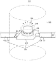
- FIG. 2 is a perspective view of a magnetic field generating unit according to the embodiment of FIG. 1.
- FIG. 3 is a perspective view of a magnetic field generating unit according to another embodiment of FIG. 1.
- FIG. 4 is a perspective view of a magnetic field generating unit according to still another embodiment of FIG. 1.
- FIG. 5 is a perspective view of a magnetic field generating unit according to still another embodiment of FIG. 1.
- FIG. 6 is a perspective view of a magnetic field generating unit according to still another embodiment of FIG. 1.
- FIG. 7 is a perspective view of a magnetic field generating unit according to still another embodiment of FIG. 1.
- FIG 8 and 9 are views for explaining the effect of the power efficiency improvement apparatus according to an embodiment of the present invention.
- FIG. 10 is a block diagram of an apparatus for improving power efficiency according to another embodiment of the present invention.
- spatially relative terms below “, “ beneath “, “ lower”, “ above “, “ upper” It may be used to easily describe the correlation of a device or components with other devices or components. Spatially relative terms are to be understood as including terms in different directions of the device in use or operation in addition to the directions shown in the figures. For example, when flipping a device shown in the figure, a device described as “below” or “beneath” of another device may be placed “above” of another device. Thus, the exemplary term “below” can encompass both an orientation of above and below. The device can also be oriented in other directions, so that spatially relative terms can be interpreted according to orientation.
- first, second, etc. are used to describe various elements or components, these elements or components are of course not limited by these terms. These terms are only used to distinguish one element or component from another element or component. Therefore, the first device or component mentioned below may be a second device or component within the technical idea of the present invention.
- FIG. 1 is a block diagram of an apparatus 200 for improving power efficiency according to an embodiment of the present invention
- FIG. 2 is a perspective view of an embodiment of the magnetic field generator 210 of FIG. 1.
- the power efficiency improving apparatus 200 may be connected in parallel to the power line 120 between the power supply unit 100 and the load unit 110.
- the power supply unit 100 supplies power to the load unit 110, and the load unit 110 operates by receiving power from the power supply unit 100.
- the load unit 110 may be anything that uses power, for example, a production facility, a mechanical device, a building, or the like.
- the power line 120 connects between the power supply unit 100 and the load unit 110 and supplies power to the load unit 110.
- An AC voltage may be applied to the power line 120.
- the power line 120 may include first to fourth power lines 121, 123, 125, and 127.
- the first to fourth power lines 121, 123, 125, and 127 may have the same voltage and may have different phases.
- the power line 120 is a three-phase four-wire line and includes four power lines 121, 123, 125, and 127, the present invention is not limited thereto.
- the power line 120 may be described.
- the power efficiency improving apparatus 200 may include a magnetic field generating unit 210, a conductive wire 220, and a control unit 230.
- the magnetic field generating unit 210 generates a strong magnetic field.
- the generated magnetic field may improve the conductivity of the conductive lines disposed in the power line 120 and the load unit 110 by increasing the flow velocity of the free electrons in the conductive lines disposed in the power line 120 and the load unit 110.
- the magnetic field generator 210 may generate a magnetic field of 0.1T to 1T.
- the magnetic field of less than 0.1T is somewhat insufficient to improve the power efficiency of the load unit 110, the magnetic field of more than 1T is not easy to generate.
- the conductivity of the conductive wire may decrease, and the expected life time of the magnetic field generator 210 may be shortened.
- the conductive wire 220 is necessary to exert a magnetic field effect on the load unit 110 and the power line 100.
- One end of the conductive wire 220 is connected to the power line 120, and the other end of the conductive wire 220 is connected to the control unit 230.
- the conductive wire 220 is not directly connected to the magnetic field generator 210, but passes through the magnetic field generated by the magnetic field generator 210.
- the control unit 230 is connected to the other end of the conductive wire 220.
- the controller 230 may control a voltage and a current flowing in the conductive wire 220.
- the control unit 230 may apply an AC voltage equal to the AC voltage applied to the power line 120 to the conductive wire 220 and prevent overcurrent of the conductive wire 220.
- the number of the magnetic field generator 210 and the conductive wire 220 may correspond to the number of the power lines 120.
- four magnetic field generators 210 may be provided and four conductive lines 220 may be provided.
- the conductive lines 220 may also correspond to the respective power lines 121.
- 123, 125, and 127 may be four.
- one end of the first sub lead 221 is connected to the first power line 121, and the first sub lead 221 passes through a magnetic field generated by the first magnetic field generator 241, and the first sub lead 221 is connected to the first power line 121.
- the other end of the conductive line 221 may be connected to the control unit 230.
- One end of the second sub lead 223 is connected to the second power line 123, and the second sub lead 223 passes through a magnetic field generated by the second magnetic field generator 243, and the second sub lead 223 The other end of) may be connected to the control unit 230.
- One end of the third sub lead 225 is connected to the third power line 125, and the third sub lead 225 passes through a magnetic field generated by the third magnetic field generator 245, and the third sub lead 225 The other end of) may be connected to the control unit 230.
- One end of the fourth sub lead wire 227 is connected to the fourth power line 127, and the fourth sub lead wire 227 passes through a magnetic field generated by the fourth magnetic field generator 247, and the fourth sub lead wire 227.
- the other end of may be connected to the control unit 230.
- the magnetic field generator 210 will be described.
- four magnetic field generators 241, 243, 245, and 247 are illustrated. Since the four magnetic field generators 241, 243, 245, and 247 have the same shape, the following description will be made only once.
- the magnetic field generator 210 may include a magnetic body 310 and a fixing part 330.
- the magnetic body 310 may generate a strong magnetic field 320.
- the magnetic body 310 may generate a magnetic field 320 having a size of 0.1T to 1T.
- the magnetic body 310 is shown as being circular, the present invention is not limited thereto.
- the fixing part 330 may be disposed between the conductive plate 410 and the magnetic body 310, and may prevent the conductive plate 410 from contacting the magnetic body 310.
- the conductive plate 410 may be spaced apart from the magnetic body 310 by the fixing part 330.
- the fixing part 330 may fix the conductive plate 410 to be located inside the magnetic field 320.
- the magnetic material 310 and the conductive plate 410 may be attached to the fixing part 330 by applying an adhesive to the surface of the fixing part 330, but the present invention is not limited thereto.
- the fixing part 330 may be made of a material other than a conductor.
- the conductive wire 220 passing through the magnetic field generator 210 may include a conductive plate 410, a first conductive wire part 420, and a second conductive wire part 430.
- the first conductive part 420 may be coated with the first insulating member 423 to prevent a short and to protect the first conductive part 420 from an external environment.
- the first conductive part 420 may be connected to the power line 120.
- the second conductive part 430 may also be coated with the second insulating member 433 to prevent short and to protect the second conductive part 430 from the external environment.
- the second conductive part 430 may be connected to the control part 230.
- the conductive plate 410 may be disposed between the first conductive part 420 and the second conductive part 430.
- the conductive plate 410 may be affected by the magnetic field 320 by passing through the space in which the magnetic field 320 is generated.
- the conductive plate 410 may be formed to have a larger area than the first and second conductive parts 420 and 430 in order to be affected by the magnetic field 320 as much as possible.
- the first width W1 of the conductive plate 410 is greater than the second width W2 of the first and second conductive parts 420 and 430. Since the conductive plate 410 has a large area, an area occupying a space in which the magnetic field 420 is formed may be larger than that of the first and second conductive parts 420 and 430.
- the conductive plate 410 may be spaced apart from the magnetic body 310 in the magnetic field 320 by the fixing part 330.
- the conductive plate 410 is illustrated as being disposed under the magnetic body 310.
- the present invention is not limited thereto, and the fixing part 330 and the conductive plate 410 are stacked on the magnetic body 310. It may be formed in a structure that is.
- the flow rate of free electrons in the conductive lines of the first and second conductive parts 420 and 430, the power line 120, and the load part 110 is sequentially increased. You can.
- the encapsulant 500 may mold them.
- the encapsulant 500 may be a non-conductive material, for example, epoxy, but is not limited thereto.
- the encapsulant 500 is illustrated as having a cylindrical shape, the present invention is not limited thereto, and the encapsulant 500 may be formed to have various shapes.
- the fixing part 330 may not be disposed. That is, the encapsulant 500 may mold a position where the fixing part 330 is disposed. Therefore, the encapsulant 500 may perform the role of fixing the conductive plate 410 and the magnetic material 310 and fixing the conductive plate 410 instead of the fixing part 330.
- FIG. 3 is a perspective view of a magnetic field generator 211 according to another embodiment of FIG. 1.
- the magnetic field generator 211 may include a plurality of magnetic bodies 311 and 312.
- the first magnetic material 311 may be disposed, and the second magnetic material 312 may be spaced apart from the first magnetic material 311.
- the first and second magnetic bodies 311 and 312 are illustrated to be disposed up and down, but the present invention is not limited thereto.
- three or more magnetic bodies may be disposed, for example.
- the first magnetic body 311 may generate a first magnetic field 321, and the second magnetic body 312 may generate a second magnetic field 322. Since the strength of the magnetic field increases when the first magnetic field 321 and the second magnetic field 322 overlap, the first magnetic body 311 and the second magnetic body 312 have the first magnetic field 321 and the second magnetic field 322. These are spaced enough to overlap. Between the first and second magnetic bodies 311 and 312, one surface of the first magnetic body 311 and one surface of the second magnetic body 312 that face each other so that the first magnetic field 321 and the second magnetic field 322 may merge. Silver may have different polarities. In FIG. 2, for example, the lower surface of the first magnetic material 311 facing each other is S-pole, and the upper surface of the second magnetic material 312 is N-pole.
- the conductive wire 220 may pass between the first and second magnetic bodies 311 and 312.
- a first fixing part 331 is disposed between the conductive plate 410 and the first magnetic body 311.
- the second fixing part 332 may be disposed between the second magnetic bodies 312.
- the first and second fixing parts 331 and 332 may be made of a material other than a conductor.
- the sum of the strengths of the first and second magnetic fields 321 and 322 generated by the first and second magnetic bodies 311 and 312 may be 0.1T to 1T.
- the encapsulant 500 may be formed to mold the first and second magnetic bodies 311 and 312, the conductive plate 410, and the first and second fixing parts 331 and 332.
- FIG. 4 is a perspective view of a magnetic field generator 211 according to another embodiment of FIG. 1.
- the magnetic field generator 213 may generate the magnetic field 323 using the solenoid 313.
- the solenoid 313 may include a solenoid seam 313_1 and a solenoid lead 313_2 surrounding the solenoid seam 313_1.
- Solenoid shim 313_1 may be, for example, a ferromagnetic material.
- the solenoid wire 313_2 may be connected to the control unit 230 to receive power. When power is supplied to the solenoid lead 313_2 and a current flows, the magnetic field 323 is generated in the solenoid 313 as shown in FIG. 4.
- the conductive plate 410 may be disposed to pass through the magnetic field 323, and the fixing part 330 is disposed between the solenoid 313 and the conductive plate 410 so that the conductive plate 410 is disposed in the magnetic field 323.
- the fixing part 330 may be fixed to be spaced apart from the solenoid 313.
- the magnetic field generator 210 of FIG. 2 when the magnetic material is used as the solenoid 313, additional power consumption occurs because power is supplied to the solenoid 313 to generate the magnetic field 323.
- the amount of power saved in the load unit 110 is much larger than the amount of power for generating the magnetic field 323.
- the magnetic field 320 of the magnetic body 310 may decrease with time, but when the solenoid 313 is used, the strength of the magnetic field 323 does not change over time.
- the magnetic field 323 strength of the solenoid 313 may be 0.1T to 1T.
- FIG. 5 is a perspective view of a magnetic field generator 213 according to another embodiment of FIG. 1.
- the magnetic field generator 213 may include a plurality of solenoids.
- the first solenoid 313 may be disposed, and the second solenoid 314 may be spaced apart from the first solenoid 313.
- the first and second solenoids 313 and 314 are illustrated to be disposed up and down, but the present invention is not limited thereto.
- the solenoid may be arranged, for example three or more.
- the first and second solenoids 313 and 314 may include the first and second solenoid shims 313_1 and 314_1 and the first and second solenoid leads 313_2 surrounding the first and second solenoid shims 313_1 and 314_1, respectively. , 314_2).
- the first solenoid 313 may generate a first magnetic field 323, and the second solenoid 314 may generate a second magnetic field 324. Since the strength of the magnetic field increases only when the first magnetic field 323 and the second magnetic field 324 are combined, the first solenoid 313 and the second solenoid 314 may be the first magnetic field 323 and the second magnetic field 324. Spaced enough to overlap. Between the first and second solenoids 313, 314, one side of the first solenoid 313 and one side of the second solenoid 314 for joining the first magnetic field 323 and the second magnetic field 324. Silver may have different polarities. In FIG. 5, the lower surface of the first solenoid 313 facing each other is S-pole, and the upper surface of the second solenoid 314 is N-pole.
- the lead 220 may pass between the first and second solenoids 313 and 314.
- a first fixing part 331 is provided between the conductive plate 410 and the first solenoid 313, and the conductive plate 410 is provided.
- the second fixing part 332 may be disposed between the second solenoid 314 and the second solenoid 314.
- the sum of the strengths of the first and second magnetic fields 323 and 324 generated by the first and second solenoids 313 and 314 may be 0.1T to 1T.
- the encapsulant 500 may be formed to mold the first and second solenoids 313 and 314, the conductive plate 410, and the first and second fixing parts 331 and 332.
- FIG. 6 is a perspective view of a magnetic field generator 214 according to another embodiment of FIG. 1.
- the magnetic field generator 214 may include a solenoid 313 and a magnetic body 310.
- the solenoid 313 may be disposed and the magnetic body 310 may be spaced apart from the first solenoid 313.
- the solenoid 313 is illustrated as being disposed on the magnetic body 310, but is not limited thereto.
- the solenoid 313 may be disposed below the magnetic body 310.
- the solenoid 313 may include a solenoid lead 313_1 and a solenoid lead 313_2 surrounding the solenoid shim 313_1.
- the solenoid lead 313_2 may be connected to the control unit 230 to receive power.
- the solenoid 313 and the magnetic body 310 may generate magnetic fields 323 and 320, respectively.
- one surface of the opposing first solenoid 313 and one surface of the magnetic body 310 may have different polarities.
- the lower surface of the solenoid 313 facing each other is S-pole
- the upper surface of the magnetic body 310 is N-pole.
- the conductive wire 220 may pass between the solenoid 313 and the magnetic body 310.
- the fixing part 330 between the conductive plate 410 and the solenoid 313, and between the conductive plate 410 and the solenoid 310, respectively. May be arranged.
- the sum of the strengths of the first and second magnetic fields 323 and 324 generated by the first and second solenoids 313 and 314 may be 0.1T to 1T.
- the encapsulant 500 may be formed to mold the first and second solenoids 313 and 314, the conductive plate 410, and the first and second fixing parts 331 and 332.
- FIG. 7 is a perspective view of a magnetic field generator 215 according to another embodiment of FIG. 1.
- the magnetic field generating unit 215 may include a plurality of magnetic bodies 311 and 312 and a plurality of solenoids 313a to 313f. Specifically, like the magnetic field generating unit 211 of FIG. 3, the first magnetic body 311 and the second magnetic body 312 are disposed, and the plurality of solenoids 313a surround the first and second magnetic bodies 311 and 312. ⁇ 313f) can be placed. The plurality of solenoids 313a to 313f and the plurality of magnetic bodies 311 and 312 are spaced apart from each other. In FIG. 7, the plurality of solenoids 313a to 313f are illustrated to be positioned at the vertices of six parallel hexagons, but the present invention is not limited thereto.
- each of the plurality of solenoids 313a to 313f may be connected to the control unit 230 and may receive power from the control unit 230 to form a magnetic field.
- the conductive plate 410 is positioned in a magnetic field generated by the plurality of solenoids 313a to 313f and the plurality of magnetic bodies 311 and 312. The conductive plate 410 is in contact with the plurality of solenoids 313a to 313f and the plurality of magnetic bodies 311 and 312.
- the first conductive part 420 and the second conductive part 430 pass between the plurality of solenoids 313a to 313f and are connected to the conductive plate 410. Since the first and second conductive parts 420 and 430 are respectively covered by the first and second insulating members 423 and 433, the first and second conductive parts 430 also have a plurality of solenoids 313a to 313f. Contactless).
- the total magnetic field generated by the plurality of solenoids 313a to 313f and the plurality of magnetic bodies 311 and 312 may be 0.1T to 1T. Since a magnetic field is generated by the plurality of solenoids 313a to 313f and the plurality of magnetic bodies 311 and 312, the magnitude of the magnetic field generated by each of the magnetic fields may be small.
- the first fixing part 331 may be disposed between the conductive plate 410 and the first magnetic body 311, and the second fixing part 332 may be disposed between the conductive plate 410 and the second magnetic body 312.
- the first and second fixing parts 331 and 332 may be made of a material other than a conductor.
- the encapsulant 500 may be formed to mold the plurality of solenoids 313a to 313f, the plurality of magnetic bodies 311. 312, the conductive plate 410, and the first and second fixing parts 331 and 332.
- FIGS. 8 and 9 are views for explaining the effect of the power efficiency improving apparatus 200 according to an embodiment of the present invention.
- Figure 8 is a line graph for Table 1
- Figure 9 is a bar graph showing the effect of the present invention on a weekly basis.
- the power efficiency improvement device 200 is connected to the power line (three-phase four-wire, 380V) supplied to the entire production line equipment (corresponding to the load unit 110 of FIG. 1), and the amount of power used and produced by the production line equipment per day The production capacity produced by the line equipment per day was measured. And through this, it was calculated how much power used compared to the production. Since the amount of electricity used and the amount of production used in the production line equipment is slightly different every day, the power consumption compared to the output was calculated to accurately grasp the effect.
- the production unit of the production line is tons and the power unit is kwh.
- the power efficiency improving apparatus 200 when the power efficiency improving apparatus 200 is installed in the production line facility, it can be confirmed that the power consumption compared to the production amount in the production line facility is reduced compared to before the installation.
- the power efficiency improving apparatus 200 improves the flow rate of the free electrons flowing in the power lines 120 and the conducting wires of the load unit 110, and the improvement is sequentially performed from the side closer to the power efficiency improving apparatus 200. Therefore, a certain time is required in order for the power efficiency improvement effect to appear in the entire production line equipment, and therefore, immediately after the power efficiency improvement apparatus 200 is installed, the improvement effect does not appear immediately, but gradually starts to appear over time.
- the power consumption compared to the average yield during the week after installation was 0.0334kwh / t, which is 0.6% lower than 0.0336kwh / t before installation.
- the power consumption compared to the average output for the two weeks after installation was 0.0318kwh / t, which was 5.4% lower than before the installation, and the power consumption compared to the average production for the three weeks after installation was 0.0311kwh / t, 7.4. % Decrease.
- the amount of power per day used by the production line equipment is several thousand kwh, it is possible to confirm the excellent power saving effect of the power efficiency improving apparatus 200.
- a power efficiency improving apparatus 201 according to another embodiment of the present invention will be described with reference to FIG. 10. Descriptions overlapping with those described above will be omitted and explanations will be provided based on differences.
- 10 is a block diagram of an apparatus 201 for improving power efficiency according to another embodiment of the present invention.
- the power efficiency improving apparatus 201 of FIG. 10 is connected in series between the power supply unit 100 and the load unit 110.
- the power efficiency improving apparatus 201 includes a first conductive wire 220a, a second conductive wire 220b, a magnetic field generator 210, and a controller 230.
- the power supply unit 100 supplies power to three-phase four lines.
- the first conductive wire 220a includes four conductive wires 221_1, 223_1, 225_1, and 227_1
- the second conductive wire 220b includes four conductive wires 221_2, 223_2, 225_2, and 227_2.
- the number of the first and second conductive wires 220a and 220b may vary according to the voltage provided by the power supply unit 100.
- the first conductive wire 220a is connected to the power supply unit 100 and passes through the magnetic field generating unit 241 to the control unit 230.
- the first sub lead 221_1 passes through the first magnetic field generator 241 and is connected to the control unit 230
- the second sub lead 223_1 passes through the second magnetic field generator 243.
- the third sub lead 225_1 passes through the third magnetic field generator 245, and is connected to the control unit 230
- the fourth sub lead 227_1 is connected to the fourth magnetic field generator. Passed through 247 is connected to the control unit 230.
- the second conductive wire 220b connects between the control unit 230 and the load unit 110.
- the first conductive wire 220a includes the first to fourth sub wires 221_1, 223_1, 225_1, and 227_1
- the second conductive wire 220b also includes the fifth to eighth sub wires 221_2, 223_2, and 225_2. , 227_2).
- the number of the first conductive wire 220a and the second conductive wire 220b is the same.
- the fifth sub lead 221_2 is connected to the first sub lead 221_1 and the control unit 230
- the sixth sub lead 223_2 is connected to the second sub lead 223_1 and the control unit 230.
- the seventh sub lead 225_2 is connected to the third sub lead 225_1 through the control unit 230
- the eighth sub lead 227_2 connects the fourth sub lead 227_1 and the control unit 230. Connected through.
- the shape of the magnetic field generating unit 210 and the shape of the first conductive line 220a passing through the magnetic field generating unit 210 of the power efficiency improving apparatus 201 of FIG. 10 are the same as those shown in FIGS. 2 to 7. The description will be omitted.
- the controller 230 may control voltages and currents flowing through the first and second conductive lines 220a and 220b.
- the control unit 230 may prevent overcurrent of the first and second conductive lines 220a and 220b.
Landscapes
- Engineering & Computer Science (AREA)
- Health & Medical Sciences (AREA)
- Life Sciences & Earth Sciences (AREA)
- Bioinformatics & Cheminformatics (AREA)
- Power Engineering (AREA)
- Organic Chemistry (AREA)
- Wood Science & Technology (AREA)
- Zoology (AREA)
- Chemical & Material Sciences (AREA)
- General Health & Medical Sciences (AREA)
- Computer Networks & Wireless Communication (AREA)
- Biomedical Technology (AREA)
- Microbiology (AREA)
- Biotechnology (AREA)
- Biochemistry (AREA)
- Genetics & Genomics (AREA)
- Sustainable Development (AREA)
- General Engineering & Computer Science (AREA)
- Molecular Biology (AREA)
- Pathology (AREA)
- Surgery (AREA)
- Animal Behavior & Ethology (AREA)
- Public Health (AREA)
- Veterinary Medicine (AREA)
- Immunology (AREA)
- Medical Informatics (AREA)
- Heart & Thoracic Surgery (AREA)
- Emergency Protection Circuit Devices (AREA)
- Inverter Devices (AREA)
Abstract
전력 효율 개선 장치가 제공된다. 전력 효율 개선 장치는, 자기장을 생성하는 자성체, 상기 자기장을 통과하고, 교류전압이 인가된 전력선에 일단이 직접 연결되는 도선, 상기 도선의 타단과 연결되고, 상기 전력선에 인가된 교류전압과 동일한 교류전압을 상기 도선에 인가하고, 상기 도선의 과전류를 방지하는 컨트롤부를 포함하되, 상기 도선은 도전판을 포함하고, 상기 도전판은 상기 자기장이 형성되는 공간에 상기 자성체와 이격되어 배치되고, 상기 도전판의 제1 폭은 상기 도선의 제2 폭보다 크다.
Description
본 발명은 도선의 전도도를 향상시키고, 저항에 의한 열 손실을 줄일 수 있는 전력 효율 개선 장치에 관한 것이다.
친환경 대체 에너지 기술 개발의 지연으로 인하여 에너지 부족 사태는 전 세계가 공통적으로 겪는 문제이다. 에너지 부족 사태를 해결하기 위한 방법으로 1) 친환경 대체 에너지 및 2) 고효율 전력 소자의 개발이 진행되어 왔으며, 이와 더불어 최근에는 전기 소자의 효율을 외부 장치를 통해 개선할 수 있는 방안에 대한 관심이 고조되고 있다.
예를 들어, 교류 전류를 활용하고 있는 대부분의 전기 소자는 실제적으로는 불완전한 교류 파형 특성으로 인하여 이상(abnormal) 전압 및 고조파 파형에 의한 손실이 나타나며, 이를 해결하기 위하여 전력 공급 장치인 전력 설비에 파형을 일정하게 유지하는 전기 회로를 설치하는 기술이 적용되고 있다.
그러나, 전력 설비가 공급하는 교류 전류의 파형을 일정하게 유지하는 회로 기술은 전기 소자 효율 개선에 일부 도움을 주고 있으나 근본적인 전기 소자 효율 향상의 해결책이 될 수는 없다. 그 이유는 전기 소자의 효율을 저하하는 주된 요인이 도선 내 진행하는 자유전자의 무작위 운동 및 이에 따른 다른 원자 진동 운동과의 충돌 즉, 저항에서 기인하기 때문이다. 따라서, 전기 소자의 효율 향상을 위해서는 무작위 운동의 자유전자를 일정 방향으로 정렬하여, 다른 원자 또는 자유전자와의 충돌 확률을 줄이고, 이에 따라 자유전자의 유동속도(drift velocity)를 증가시키는 방안을 생각할 수 있다. 즉, 자유전자의 유동속도가 증가하면, 도체의 전도도(conductivity)가 향상되므로 전기 소자 효율 감소의 원인이 되었던 저항에 의한 열손실을 감소시킬 수 있다.
본 발명이 해결하고자 하는 과제는, 강한 자기장을 발생시키고, 이를 통해 자유전자의 유동 속도 및 도선의 전도도를 향상시켜 전력 효율을 개선하는 전력 효율 개선 장치를 제공하는 것이다.
본 발명이 해결하고자 하는 과제들은 이상에서 언급한 과제들로 제한되지 않으며, 언급되지 않은 또 다른 과제들은 아래의 기재로부터 당업자에게 명확하게 이해될 수 있을 것이다.
상기 과제를 달성하기 위한 본 발명의 일 실시예에 따른 전력 효율 개선 장치는, 자기장을 생성하는 자성체, 상기 자기장을 통과하고, 교류전압이 인가된 전력선에 일단이 직접 연결되는 도선, 상기 도선의 타단과 연결되고, 상기 전력선에 인가된 교류전압과 동일한 교류전압을 상기 도선에 인가하고, 상기 도선의 과전류를 방지하는 컨트롤부를 포함하되, 상기 도선은 도전판을 포함하고, 상기 도전판은 상기 자기장이 형성되는 공간에 상기 자성체와 이격되어 배치되고, 상기 도전판의 제1 폭은 상기 도선의 제2 폭보다 크다.
상기 자기장은 0.1T 내지 1T의 크기를 가질 수 있다.
상기 도선을 피복하는 절연 부재를 더 포함하고, 상기 도전판은 피복되지 않을 수 있다.
상기 자성체와 상기 도전판 사이에 형성되고, 상기 도전판을 상기 자기장 내부에 위치하도록 고정하는 고정부를 더 포함할 수 있다.
상기 자성체는 제1 자성체와, 상기 제1 자성체와 이격되어 배치되는 제2 자성체를 포함하고, 상기 제1 및 제2 자성체의 서로 마주보는 면의 극성은 서로 다를 수 있다.
상기 도선은 상기 제1 자성체와 상기 제2 자성체 사이를 통과할 수 있다.
상기 자성체는 솔레노이드일 수 있다. 상기 솔레노이드는, 강자성체와, 상기 강자성체를 감는 솔레노이드 도선을 포함하고, 상기 솔레노이드 도선은 상기 컨트롤부와 연결되어 상기 컨트롤부로부터 전원을 공급받을 수 있다.
상기 솔레노이드는 제1 솔레노이드와, 상기 제1 솔레노이드로부터 이격되어 배치되는 제2 솔레노이드를 포함하고, 상기 도선은 상기 제1 솔레노이드와 상기 제2 솔레노이드 사이를 통과할 수 있다.
상기 자성체는, 상하로 이격되어 배치되는 제1 및 제2 자성체와, 상기 제1 및 제2 자성체를 둘러싸는 복수개의 솔레노이드를 포함하되, 상기 도선은, 상기 제1 및 제2 자성체 사이에서, 상기 제1 자성체, 제2 자성체 및 상기 복수개의 솔레노이드 각각의 자기장이 겹치는 부분을 통과할 수 있다.
상기 자성체, 상기 도전판이 배치된 공간을 몰딩하는 봉지재를 더 포함할 수 있다.
상기 과제를 달성하기 위한 본 발명의 다른 실시예에 따른 전력 효율 개선 장치는, 서로 다른 상을 갖는 복수개의 전력선과 일대일 대응하는 복수개의 자기장 생성부, 각각의 일단이 상기 복수개의 전력선 각각과 하나씩 연결되고, 상기 복수개의 자기장 생성부 각각이 생성한 자기장을 통과하는 복수개의 도선, 상기 복수개의 도선의 타단과 연결되고, 상기 복수개의 도선에 흐르는 전압과 전류를 제어하는 컨트롤부를 포함한다.
상기 컨트롤부는, 상기 복수개의 도선 각각이 연결된 상기 복수개의 전력선 각각의 교류전압과 동일한 교류전압을 상기 복수개의 도선 각각에 인가하며, 상기 복수개의 도선의 과전류를 방지하고, 상기 복수개의 자기장 생성부 각각은 0.1T 내지 1T의 자기장을 생성할 수 있다.
상기 복수개의 도선 각각은, 절연 부재로 피복된 도선부와, 도전판을 포함하고, 상기 도전판은 상기 자기장 생성부가 생성한 자기장 내에 위치할 수 있다.
상기 복수개의 자기장 생성부 각각은, 상기 자기장을 생성하는 자성체와, 상기 자성체와 상기 도전판 사이에 배치되는 고정부와, 상기 자성체, 상기 고정부, 및 상기 도전판을 몰딩하는 봉지재를 포함할 수 있다.
상기 과제를 달성하기 위한 본 발명의 또다른 실시예에 따른 전력 효율 개선 장치는, 자기장을 생성하는 자성체, 상기 자기장을 통과하고, 일단이 교류전원부에 연결되는 제1 도선, 상기 제1 도선의 타단과 연결되고, 상기 도선의 과전류를 방지하는 컨트롤부, 및 상기 컨트롤부와 부하부 사이를 연결하는 제2 도선을 포함한다.
상기 제1 도선은 도전판을 포함하고, 상기 도전판은 상기 자기장 내에 상기 자성체와 이격되어 배치되고, 상기 도전판의 제1 폭은 상기 도선의 제2 폭보다 클 수 있다.
상기 자기장은 0.1T 내지 1T의 크기를 가질 수 있다.
상기 자성체는 복수개이고, 상기 제1 도선은, 상기 복수개의 자성체 각각의 자기장이 겹치는 부분에 배치될 수 있다.
상기 제1 도선을 피복하고, 상기 도전판은 피복하지 않는 절연 부재를 더 포함할 수 있다.
상기 자성체와 상기 도전판 사이에 형성되고, 상기 도전판을 상기 자기장 내부에 위치하도록 고정하는 고정부를 더 포함할 수 있다.
상기 자성체는 제1 자성체와, 상기 제1 자성체와 이격되어 배치되는 제2 자성체를 포함하고, 상기 제1 및 제2 자성체의 서로 마주보는 면의 극성은 서로 다를 수 있다.
상기 제1 도선은 상기 제1 자성체와 상기 제2 자성체 사이를 통과할 수 잇다.
상기 자성체는 솔레노이드일 수 있다.
상기 솔레노이드는, 솔레노이드 심과, 상기 솔레노이드 심을 감는 솔레노이드 도선을 포함하고, 상기 솔레노이드 도선은 상기 컨트롤부와 연결되어 상기 컨트롤부로부터 전원을 공급받을 수 있다.
상기 솔레노이드는 제1 솔레노이드와, 상기 제1 솔레노이드로부터 이격되어 배치되는 제2 솔레노이드를 포함하고, 상기 제1 도선은 상기 제1 솔레노이드와 상기 제2 솔레노이드 사이를 통과할 수 있다.
본 발명의 기타 구체적인 사항들은 상세한 설명 및 도면들에 포함되어 있다.
본 발명에 따르면, 부하부의 전력 효율을 개선하여 부하부에서의 전력 사용량을 감소할 수 있다.
도 1은 본 발명의 일 실시예에 따른 전력 효율 개선 장치에 대한 블록도이다.
도 2는 도 1의 일 실시예에 따른 자기장 생성부의 사시도이다.
도 3은 도 1의 다른 실시예에 따른 자기장 생성부의 사시도이다.
도 4는 도 1의 또다른 실시예에 따른 자기장 생성부의 사시도이다.
도 5는 도 1의 또다른 실시예에 따른 자기장 생성부의 사시도이다.
도 6은 도 1의 또다른 실시예에 따른 자기장 생성부의 사시도이다.
도 7은 도 1의 또다른 실시예에 따른 자기장 생성부의 사시도이다.
도 8 및 도 9는 본 발명의 일 실시예에 따른 전력 효율 개선 장치의 효과를 설명하기 위한 도면이다.
도 10은 본 발명의 다른 실시예에 따른 전력 효율 개선 장치에 대한 블록도이다.
본 발명의 이점 및 특징, 그리고 그것들을 달성하는 방법은 첨부되는 도면과 함께 상세하게 후술되어 있는 실시예들을 참조하면 명확해질 것이다. 그러나 본 발명은 이하에서 개시되는 실시예들에 한정되는 것이 아니라 서로 다른 다양한 형태로 구현될 것이며, 단지 본 실시예들은 본 발명의 개시가 완전하도록 하며, 본 발명이 속하는 기술분야에서 통상의 지식을 가진 자에게 발명의 범주를 완전하게 알려주기 위해 제공되는 것이며, 본 발명은 청구항의 범주에 의해 정의될 뿐이다. 도면에서 표시된 구성요소의 크기 및 상대적인 크기는 설명의 명료성을 위해 과장된 것일 수 있다. 명세서 전체에 걸쳐 동일 참조 부호는 동일 구성 요소를 지칭하며, "및/또는"은 언급된 아이템들의 각각 및 하나 이상의 모든 조합을 포함한다.
소자(elements) 또는 층이 다른 소자 또는 층의 "위(on)" 또는 "상(on)"으로 지칭되는 것은 다른 소자 또는 층의 바로 위뿐만 아니라 중간에 다른 층 또는 다른 소자를 개재한 경우를 모두 포함한다. 반면, 소자가 "직접 위(directly on)" 또는 "바로 위"로 지칭되는 것은 중간에 다른 소자 또는 층을 개재하지 않은 것을 나타낸다.
공간적으로 상대적인 용어인 "아래(below)", "아래(beneath)", "하부(lower)", "위(above)", "상부(upper)" 등은 도면에 도시되어 있는 바와 같이 하나의 소자 또는 구성 요소들과 다른 소자 또는 구성 요소들과의 상관관계를 용이하게 기술하기 위해 사용될 수 있다. 공간적으로 상대적인 용어는 도면에 도시되어 있는 방향에 더하여 사용시 또는 동작시 소자의 서로 다른 방향을 포함하는 용어로 이해되어야 한다. 예를 들면, 도면에 도시되어 있는 소자를 뒤집을 경우, 다른 소자의 "아래(below)" 또는 "아래(beneath)"로 기술된 소자는 다른 소자의 "위(above)"에 놓여질 수 있다. 따라서, 예시적인 용어인 "아래"는 아래와 위의 방향을 모두 포함할 수 있다. 소자는 다른 방향으로도 배향될 수 있고, 이에 따라 공간적으로 상대적인 용어들은 배향에 따라 해석될 수 있다.
본 명세서에서 사용된 용어는 실시예들을 설명하기 위한 것이며 본 발명을 제한하고자 하는 것은 아니다. 본 명세서에서, 단수형은 문구에서 특별히 언급하지 않는 한 복수형도 포함한다. 명세서에서 사용되는 "포함한다(comprises)" 및/또는 "포함하는(comprising)"은 언급된 구성요소 외에 하나 이상의 다른 구성요소의 존재 또는 추가를 배제하지 않는다.
비록 제1, 제2 등이 다양한 소자나 구성요소들을 서술하기 위해서 사용되나, 이들 소자나 구성요소들은 이들 용어에 의해 제한되지 않음은 물론이다. 이들 용어들은 단지 하나의 소자나 구성요소를 다른 소자나 구성요소와 구별하기 위하여 사용하는 것이다. 따라서, 이하에서 언급되는 제1 소자나 구성요소는 본 발명의 기술적 사상 내에서 제2 소자나 구성요소 일 수도 있음은 물론이다.
다른 정의가 없다면, 본 명세서에서 사용되는 모든 용어(기술 및 과학적 용어를 포함)는 본 발명이 속하는 기술분야에서 통상의 지식을 가진 자에게 공통적으로 이해될 수 있는 의미로 사용될 수 있을 것이다. 또 일반적으로 사용되는 사전에 정의되어 있는 용어들은 명백하게 특별히 정의되어 있지 않는 한 이상적으로 또는 과도하게 해석되지 않는다.
도 1 및 도 2를 참조하여, 본 발명의 일 실시예에 따른 전력 효율 개선 장치(200) 대하여 설명하기로 한다. 도 1은 본 발명의 일 실시예에 따른 전력 효율 개선 장치(200)에 대한 블록도이고, 도 2는 도 1의 자기장 생성부(210)의 일 실시예에 따른 사시도이다.
도 1을 참조하면, 전력 효율 개선 장치(200)는 전원부(100)와 부하부(110) 사이의 전력선(120)에 병렬 연결될 수 있다. 전원부(100)는 부하부(110)에 전력을 공급하고, 부하부(110)는 전원부(100)로부터 전력을 공급받아 동작한다. 부하부(110)는 예를 들어, 생산 설비, 기계 장치, 빌딩 등 전력을 사용하는 것이면 무엇이든지 될 수 있다.
전력선(120)은 전원부(100)와 부하부(110) 사이를 연결하고 부하부(110)에 전력을 공급한다. 전력선(120)에는 교류 전압이 인가될 수 있다. 전력선(120)은 제1 내지 제4 전력선(121, 123, 125, 127)을 포함할 수 있다. 제1 내지 제4 전력선(121, 123, 125, 127)은 같은 전압을 갖고, 서로 다른 상(phase)을 가질 수 있다. 도 1에서는 전력선(120)이 3상 4선이고, 4개의 전력선(121, 123, 125, 127)을 포함하는 것으로 도시되어 있으나, 본 발명이 이에 제한되는 것은 아니며, 예를 들어, 전력선(120)은 3상 3선이고, 3개의 전력선을 포함할 수 있고, 3상이 아닌 4상 등일 수도 있다.
전력 효율 개선 장치(200)는 자기장 생성부(210), 도선(220), 컨트롤부(230)를 포함할 수 있다.
자기장 생성부(210)는 강한 자기장을 생성한다. 생성된 자기장은 전력선(120) 및 부하부(110)에 배치된 도선 내의 자유전자의 유동속도를 증가시켜 전력선(120) 및 부하부(110)에 배치된 도선의 전도도를 향상시킬 수 있다.
자기장 생성부(210)는 0.1T 내지 1T의 자기장을 생성할 수 있다. 0.1T 미만의 자기장은 부하부(110)의 전력 효율을 개선하기에 다소 부족하고, 1T 초과의 자기장은 생성하기 쉽지 않다. 또한, 자기장의 세기가 클수록 오히려 도선의 전도도가 감소하고 자기장 생성부(210)의 기대 수명(life time)이 짧아질 수 있다.
도선(220)은 부하부(110)와 전력선(100)에 자기장의 효과를 미치기 위하여 필요하다. 도선(220)의 일단은 전력선(120)과 연결되고, 도선(220)의 타단은 컨트롤부(230)와 연결된다. 도선(220)은 자기장 생성부(210)와 직접적으로 연결되지 않으며, 자기장 생성부(210)가 생성한 자기장을 통과한다.
컨트롤부(230)는 도선(220)의 타단과 연결된다. 컨트롤부(230)는 도선(220)에 흐르는 전압과 전류를 제어할 수 있다. 구체적으로, 컨트롤부(230)는 전력선(120)에 인가된 교류전압과 동일한 교류전압을 도선(220)에 인가하고, 도선(220)의 과전류를 방지할 수 있다.
자기장 생성부(210)와 도선(220)의 개수는 전력선(120)의 개수에 대응할 수 있다. 예를 들어, 전력선(120)이 4개인 경우, 자기장 생성부(210)도 4개이고 도선(220)도 4개일 수 있다. 도 1에서는 전력선(120)이 4개인 것으로 도시되어 있으므로, 자기장 생성부(210)도 각각의 전력선(121, 123, 125, 127)과 대응하도록 4개이고, 도선(220)도 각각의 전력선(121, 123, 125, 127)과 대응하도록 4개일 수 있다. 구체적으로, 제1 전력선(121)에는 제1 서브 도선(221)의 일단이 연결되고, 제1 서브 도선(221)은 제1 자기장 생성부(241)가 생성한 자기장을 통과하고, 제1 서브 도선(221)의 타단은 컨트롤부(230)와 연결될 수 있다. 제2 전력선(123)에는 제2 서브 도선(223)의 일단이 연결되고, 제2 서브 도선(223)은 제2 자기장 생성부(243)가 생성한 자기장을 통과하고, 제2 서브 도선(223)의 타단은 컨트롤부(230)와 연결될 수 있다. 제3 전력선(125)에는 제3 서브 도선(225)의 일단이 연결되고, 제3 서브 도선(225)은 제3 자기장 생성부(245)가 생성한 자기장을 통과하고, 제3 서브 도선(225)의 타단은 컨트롤부(230)와 연결될 수 있다. 제4 전력선(127)에는 제4 서브 도선(227)의 일단이 연결되고, 제4 서브 도선(227)은 제4 자기장 생성부(247)가 생성한 자기장을 통과하고, 제4 서브 도선(227)의 타단은 컨트롤부(230)와 연결될 수 있다.
도 2를 참조하여, 자기장 생성부(210)에 대하여 설명하기로 한다. 도 1에는 4개의 자기장 생성부(241, 243, 245, 247)가 도시되어 있는데, 4개의 자기장 생성부(241, 243, 245, 247) 모두 동일한 형상을 갖고 있으므로 이하에서는 한번만 설명하기로 한다.
자기장 생성부(210)는 자성체(310), 고정부(330)를 포함할 수 있다. 자성체(310)는 강한 자기장(320)을 생성할 수 있다. 자성체(310)는 0.1T 내지 1T의 크기를 갖는 자기장(320)을 생성할 수 있다. 자성체(310)가 원형인 것으로 도시되어 있지만, 본 발명이 이에 제한되는 것은 아니다.
고정부(330)는 도전판(410)과 자성체(310) 사이에 배치될 수 있으며, 도전판(410)이 자성체(310)와 접촉하는 것을 방지할 수 있다. 고정부(330)에 의하여 도전판(410)은 자성체(310)와 이격되어 배치될 수 잇다. 또한, 고정부(330)는 도전판(410)이 자기장(320) 내부에 위치할 수 있도록 고정할 수 있다.
고정부(330)의 표면에 접착제를 발라 자성체(310)와 도전판(410)을 고정부(330)에 붙일 수 있으나, 본 발명이 이에 제한되는 것은 아니다. 고정부(330)는 도체가 아닌 물질로 구성될 수 있다.
자기장 생성부(210)를 통과하는 도선(220)은 도전판(410), 제1 도선부(420), 제2 도선부(430)를 포함할 수 있다. 제1 도선부(420)는 쇼트(short)를 방지하고, 외부 환경으로부터 제1 도선부(420)를 보호하기 위하여 제1 절연 부재(423)로 피복될 수 있다. 제1 도선부(420)는 전력선(120)과 연결될 수 있다.
제2 도선부(430)도 쇼트(short)를 방지하고, 외부 환경으로부터 제2 도선부(430)를 보호하기 위하여 제2 절연 부재(433)로 피복될 수 있다. 제2 도선부(430)는 컨트롤부(230)와 연결될 수 있다.
제1 도선부(420)와 제2 도선부(430) 사이에는 도전판(410)이 배치될 수 있다. 도전판(410)은 자기장(320)이 생성된 공간을 통과하여 자기장(320)의 영향을 받을 수 있다. 도전판(410)은 자기장(320)의 영향을 최대한 받기 위하여 제1 및 제2 도선부(420, 430)보다 큰 면적을 갖도록 형성될 수 있다. 구체적으로, 도전판(410)의 제1 폭(W1)은 제1 및 제2 도선부(420, 430)의 제2 폭(W2)보다 크다. 도전판(410)의 면적이 크기 때문에 제1 및 제2 도선부(420, 430)에 비하여 자기장(420)이 형성된 공간을 차지하는 영역이 넓을 수 있다. 도전판(410)은 고정부(330)에 의하여 자기장(320) 내에 자성체(310)와 이격되어 배치될 수 있다. 도 2에서는 도전판(410)이 자성체(310) 하부에 배치되는 것으로 도시되어 있으나, 본 발명은 이에 제한되는 것은 아니고, 자성체(310) 상에 고정부(330), 도전판(410)이 적층되는 구조로 형성될 수도 있다.
도전판(410)이 자기장(320)의 영향을 받으면, 순차적으로 제1 및 제2 도선부(420, 430), 전력선(120), 부하부(110)의 도선 내 자유전자의 유동 속도를 증가시킬 수 있다.
자성체(310), 고정부(330), 도전판(410) 등을 외부 환경, 외부 충격 등으로부터 보호하기 위하여, 봉지재(500)가 이들을 몰딩(molding)할 수 있다. 봉지재(500)는 비전도성 물질일 수 있으며, 예를 들어, 에폭시(epoxy)일 수 있으나, 이에 제한되는 것은 아니다. 봉지재(500)가 원기둥 형상인 것으로 도시되어 있으나, 본 발명은 이에 제한되는 것은 아니며, 봉지재(500)는 다양한 형상을 갖도록 형성될 수 있다.
한편, 봉지재(500)를 형성하는 경우 고정부(330)를 미배치할 수 있다. 즉, 고정부(330)가 배치된 자리를 봉지재(500)가 몰딩할 수 있다. 따라서, 도전판(410)과 자성체(310)를 이격시키고 도전판(410)을 고정하는 역할을 봉지재(500)가 고정부(330) 대신 수행할 수 있다.
도 3을 참조하여, 다른 실시예에 따른 자기장 생성부(211)를 설명하기로 한다. 상술한 바와 중복되는 내용은 설명을 생략하고 차이점을 위주로 설명하기로 한다. 도 3은 도 1의 다른 실시예에 따른 자기장 생성부(211)의 사시도이다.
도 3을 참조하면, 다른 실시예에 따른 자기장 생성부(211)는 복수개의 자성체(311, 312)를 포함할 수 있다. 예를 들어, 제1 자성체(311)가 배치되고, 제1 자성체(311)와 이격되어 제2 자성체(312)가 배치될 수 있다. 도 3에서는 제1 및 제2 자성체(311, 312)가 상하로 배치되는 것으로 도시되어 있으나, 본 발명이 이에 제한되는 것은 아니다. 또한, 자성체는 예를 들어, 3개 이상이 배치될 수 있다.
제1 자성체(311)는 제1 자기장(321)을 생성하고, 제2 자성체(312)는 제2 자기장(322)을 생성할 수 있다. 제1 자기장(321)과 제2 자기장(322)이 겹쳐야 자기장의 세기가 커지므로, 제1 자성체(311)와 제2 자성체(312)는 제1 자기장(321)과 제2 자기장(322)이 겹칠 수 있을 정도로 이격된다. 제1 및 제2 자성체(311, 312) 사이에서, 제1 자기장(321)과 제2 자기장(322)이 합치기 위하여, 마주보는 제1 자성체(311)의 일면과 제2 자성체(312)의 일면은 극성이 서로 다를 수 있다. 도 2에서는 예시적으로, 마주보는 제1 자성체(311)의 하면이 S극이고 제2 자성체(312)의 상면이 N극인 것으로 도시하였다.
제1 및 제2 자성체(311, 312) 사이에서 자기장이 가장 크기 때문에, 도선(220)은 제1 및 제2 자성체(311, 312) 사이를 통과할 수 있다. 도전판(410)을 제1 및 제2 자성체(311, 312)에 배치하기 위하여 도전판(410)과 제1 자성체(311) 사이에는 제1 고정부(331)가, 도전판(410)과 제2 자성체(312) 사이에는 제2 고정부(332)가 배치될 수 있다. 제1 및 제2 고정부(331, 332)는 도체가 아닌 물질로 구성될 수 있다.
제1 및 제2 자성체(311, 312)가 생성하는 제1 및 제2 자기장(321, 322) 세기의 합은 0.1T 내지 1T 크기일 수 있다.
봉지재(500)는 제1 및 제2 자성체(311, 312), 도전판(410), 제1 및 제2 고정부(331, 332)를 몰딩하도록 형성될 수 있다.
도 4를 참조하여, 또다른 실시예에 따른 자기장 생성부(212)를 설명하기로 한다. 상술한 바와 중복되는 내용은 설명을 생략하고 차이점을 위주로 설명하기로 한다. 도 4는 도 1의 또다른 실시예에 따른 자기장 생성부(211)의 사시도이다.
도 4를 참조하면, 자기장 생성부(213)는 솔레노이드(313)를 이용하여 자기장(323)을 생성할 수 있다. 구체적으로, 솔레노이드(313)는 솔레노이드 심(313_1)과, 솔레노이드 심(313_1)을 감싸는 솔레노이드 도선(313_2)을 포함할 수 있다. 솔레노이드 심(313_1)은 예를 들어, 강자성체일 수 있다. 솔레노이드 도선(313_2)은 컨트롤부(230)와 연결되어 전원을 공급받을 수 있다. 솔레노이드 도선(313_2)에 전원이 공급되어 전류가 흐르면, 솔레노이드(313)에는 도 4에 도시된 바와 같이 자기장(323)이 생성된다. 자기장(323)을 통과하도록 도전판(410)은 배치될 수 있고, 솔레노이드(313)와 도전판(410) 사이에 고정부(330)가 배치되어 도전판(410)이 자기장(323) 내에 배치되되, 고정부(330)가 솔레노이드(313)와 이격되도록 고정할 수 있다.
도 2의 자기장 생성부(210)와 달리 자성체를 솔레노이드(313)로 사용하면, 자기장(323)을 생성하기 위하여 솔레노이드(313)에 전원을 공급해야하므로 추가적인 전력 소비가 발생한다. 그러나, 부하부(110)에서 절감되는 전력량이 자기장(323)을 생성하기 위한 전력량보다 훨씬 크다. 또한, 자성체(310)의 자기장(320)은 시간이 지나감에 따라 감소할 수 있으나, 솔레노이드(313)를 사용하는 경우 자기장(323)의 세기는 시간이 지나도 변함이 없다.
솔레노이드(313)의 자기장(323) 세기는 0.1T 내지 1T일 수 있다.
도 5를 참조하여, 또다른 실시예에 따른 자기장 생성부(213)를 설명하기로 한다. 상술한 바와 중복되는 내용은 설명을 생략하고 차이점을 위주로 설명하기로 한다. 도 5는 도 1의 또다른 실시예에 따른 자기장 생성부(213)의 사시도이다.
도 5를 참조하면, 도 4와 달리, 자기장 생성부(213)가 복수개의 솔레노이드를 포함할 수 있다. 예를 들어, 제1 솔레노이드(313)가 배치되고, 제1 솔레노이드(313)와 이격되어 제2 솔레노이드(314)가 배치될 수 있다. 도 5에서는 제1 및 제2 솔레노이드(313, 314)가 상하로 배치되는 것으로 도시되어 있으나, 본 발명이 이에 제한되는 것은 아니다. 또한, 솔레노이드는 예를 들어, 3개 이상이 배치될 수 있다. 제1 및 제2 솔레노이드(313, 314)는 각각 제1 및 제2 솔레노이드 심(313_1, 314_1)와, 제1 및 제2 솔레노이드 심(313_1, 314_1)을 감싸는 제1 및 제2 솔레노이드 도선(313_2, 314_2)을 포함할 수 있다.
제1 솔레노이드(313)는 제1 자기장(323)을 생성하고, 제2 솔레노이드(314)는 제2 자기장(324)을 생성할 수 있다. 제1 자기장(323)과 제2 자기장(324)이 합쳐야 자기장의 세기가 커지므로, 제1 솔레노이드(313)와 제2 솔레노이드(314)는 제1 자기장(323)과 제2 자기장(324)이 겹칠 수 있을 정도로 이격된다. 제1 및 제2 솔레노이드(313, 314) 사이에서, 제1 자기장(323)과 제2 자기장(324)이 합치기 위하여, 마주보는 제1 솔레노이드(313)의 일면과 제2 솔레노이드(314)의 일면은 극성이 서로 다를 수 있다. 도 5에서는 예시적으로, 마주보는 제1 솔레노이드(313)의 하면이 S극이고 제2 솔레노이드(314)의 상면이 N극인 것으로 도시하였다.
제1 및 제2 솔레노이드(313, 314) 사이에서 자기장이 가장 크기 때문에, 도선(220)은 제1 및 제2 솔레노이드(313, 314) 사이를 통과할 수 있다. 도전판(410)을 제1 및 제2 솔레노이드(313, 314) 사이에 배치하기 위하여 도전판(410)과 제1 솔레노이드(313) 사이에는 제1 고정부(331)가, 도전판(410)과 제2 솔레노이드(314) 사이에는 제2 고정부(332)가 배치될 수 있다.
제1 및 제2 솔레노이드(313, 314)가 생성하는 제1 및 제2 자기장(323, 324) 세기의 합은 0.1T 내지 1T 크기일 수 있다.
봉지재(500)는 제1 및 제2 솔레노이드(313, 314), 도전판(410), 제1 및 제2 고정부(331, 332)를 몰딩하도록 형성될 수 있다.
도 6을 참조하여, 또다른 실시예에 따른 자기장 생성부(214)를 설명하기로 한다. 상술한 바와 중복되는 내용은 설명을 생략하고 차이점을 위주로 설명하기로 한다. 도 6은 도 1의 또다른 실시예에 따른 자기장 생성부(214)의 사시도이다.
도 6을 참조하면, 자기장 생성부(214)는 솔레노이드(313)와 자성체(310)를 포함할 수 있다. 예를 들어, 솔레노이드(313)가 배치되고, 제1 솔레노이드(313)와 이격되어 자성체(310)가 배치될 수 있다. 도 6에서는 솔레노이드(313)가 자성체(310) 상에 배치되는 것으로 도시되어 있으나, 이에 제한되는 것은 아니며, 솔레노이드(313)가 자성체(310) 하부에 배치될 수도 있다.
솔레노이드(313)는 솔레노이드 심(313_1)과 솔레노이드 심(313_1)을 감싸는 솔레노이드 도선(313_2)을 포함할 수 있다. 솔레노이드 도선(313_2)은 컨트롤부(230)에 연결되어 전원을 공급받을 수 있다.
솔레노이드(313)와 자성체(310)는 각각 자기장(323, 320)을 생성할 수 있다. 각각의 자기장(323, 320)이 서로 합치기 위하여, 마주보는 제1 솔레노이드(313)의 일면과 자성체(310)의 일면은 극성이 서로 다를 수 있다. 도 6에서는 예시적으로, 마주보는 솔레노이드(313)의 하면이 S극이고 자성체(310)의 상면이 N극인 것으로 도시하였다.
도선(220), 특히 도전판(410)은 솔레노이드(313)와 자성체(310) 사이를 통과할 수 있다. 도전판(410)을 솔레노이드(313)와 자성체(310) 사이에 배치하기 위하여, 도전판(410)과 솔레노이드(313) 사이, 도전판(410)과 솔레노이드(310) 사이에는 각각 고정부(330)가 배치될 수 있다.
제1 및 제2 솔레노이드(313, 314)가 생성하는 제1 및 제2 자기장(323, 324) 세기의 합은 0.1T 내지 1T 크기일 수 있다.
봉지재(500)는 제1 및 제2 솔레노이드(313, 314), 도전판(410), 제1 및 제2 고정부(331, 332)를 몰딩하도록 형성될 수 있다.
도 7을 참조하여, 또다른 실시예에 따른 자기장 생성부(215)를 설명하기로 한다. 상술한 바와 중복되는 내용은 설명을 생략하고 차이점을 위주로 설명하기로 한다. 도 7은 도 1의 또다른 실시예에 따른 자기장 생성부(215)의 사시도이다.
도 7을 참조하면, 자기장 생성부(215)는 복수개의 자성체(311, 312)와 복수개의 솔레노이드(313a~313f)를 포함할 수 있다. 구체적으로, 도 3의 자기장 생성부(211)와 같이 제1 자성체(311)와 제2 자성체(312)를 배치하고, 제1 및 제2 자성체(311, 312)를 둘러싸도록 복수개의 솔레노이드(313a~313f)를 배치할 수 있다. 복수개의 솔레노이드(313a~313f)와 복수개의 자성체(311, 312)는 서로 이격되어 배치된다. 도 7에서는 복수개의 솔레노이드(313a~313f)가 6개이고 평행한 육각형의 꼭지점에 위치하도록 도시되어 있으나, 이에 제한되는 것은 아니고, 예를 들어, 4개 또는 8개의 솔레노이드가 제1 및 제2 자성체(311, 312) 주위에서 사각형의 꼭지점에 위치하거나, 8개의 솔레노이드가 팔각형의 꼭지점에 위치할 수도 있다. 복수개의 솔레노이드(313a~313f)는 각각 컨트롤부(230)에 연결되고, 컨트롤부(230)로부터 전원을 공급받아 자기장을 형성할 수 있다. 도전판(410)은 복수개의 솔레노이드(313a~313f)와 복수개의 자성체(311, 312)가 생성한 자기장에 위치한다. 도전판(410)은 복수개의 솔레노이드(313a~313f) 및 복수개의 자성체(311, 312)와 비접촉한다. 제1 도선부(420)와 제2 도선부(430)는 복수개의 솔레노이드(313a~313f) 사이를 통과하여 도전판(410)과 연결된다. 제1 및 제2 절연 부재(423, 433)에 의하여 제1 및 제2 도선부(420, 430)를 각각 피복하고 있기 때문에 제1 및 제2 도선부(430)도 복수개의 솔레노이드(313a~313f)와 비접촉한다.
복수개의 솔레노이드(313a~313f)와 복수개의 자성체(311, 312)가 생성하는 총 자기장의 크기는 0.1T 내지 1T일 수 있다. 복수개의 솔레노이드(313a~313f)와 복수개의 자성체(311, 312)에 의하여 자기장이 발생하기 때문에 각각이 생성하는 자기장의 크기는 작을 수 있다.
도전판(410)과 제1 자성체(311) 사이에는 제1 고정부(331)가, 도전판(410)과 제2 자성체(312) 사이에는 제2 고정부(332)가 배치될 수 있다. 제1 및 제2 고정부(331, 332)는 도체가 아닌 물질로 구성될 수 있다.
봉지재(500)는 복수개의 솔레노이드(313a~313f), 복수개의 자성체(311. 312), 도전판(410), 제1 및 제2 고정부(331, 332)를 몰딩하도록 형성될 수 있다.
도 8 및 도 9를 참조하여 본 발명의 일 실시예에 따른 전력 효율 개선 장치(200)의 효과에 대하여 설명하기로 한다. 도 8 및 도 9는 본 발명의 일 실시예에 따른 전력 효율 개선 장치(200)의 효과를 설명하기 위한 도면이다. 구체적으로, 도 8은 표 1에 대한 꺽은선 그래프이고, 도 9는 일주일 단위로 본 발명의 효과를 나타낸 막대 그래프이다.
전력 효율 개선 장치(200)의 효과를 알아보기 위하여 다음과 같이 실험을 진행하였다. 생산라인 설비 전체(도 1의 부하부(110)에 대응)에 공급하는 전력선(3상 4선, 380V)에 전력 효율 개선 장치(200)를 연결하고 생산라인 설비가 하루에 사용하는 전력량, 생산라인 설비가 하루에 생산하는 생산량을 측정하였다. 그리고 이를 통하여, 생산량 대비하여 얼마나 전력량을 사용하였는지 계산하였다. 생산라인 설비에서 하루에 사용하는 전력량과 생산량은 매일 조금씩 차이가 있기 때문에, 정확하게 효과를 파악하고자 생산량 대비 전력사용량을 구하였다. 생산라인의 생산량 단위는 톤(ton)이고 전력량 단위는 kwh이다.
표 1 
도 8에는 [표 1]의 내용을 그래프로 도시하였다.
[표 1]과 도 8을 참조하면, 생산라인 설비에 전력 효율 개선 장치(200)를 설치하면, 설치하기 전과 비교하여 생산라인 설비에서 생산량 대비 전력 사용량이 감소하는 것을 확인할 수 있다. 전력 효율 개선 장치(200)는 전력선(120) 및 부하부(110)의 도선에 흐르는 자유 전자의 유동 속도를 개선하고, 이러한 개선은 전력 효율 개선 장치(200)에 가까운 쪽부터 순차적으로 이루어진다. 따라서, 생산라인 설비 전체에 전력 효율 개선 효과가 나타나기 위해서는 일정 시간이 필요하고, 따라서 전력 효율 개선 장치(200)를 설치한 직후에 바로 개선 효과가 나타나지 않고 시간을 두고서 점차 효과가 나타나기 시작한다.
도 9에서는 일주일 단위로 평균을 내서 설치 전 생산량 대비 전력 사용량과 설치 후 생산량 대비 전력 사용량을 비교하였다.
설치 후 일주일 동안의 평균 생산량 대비 전력 사용량은 0.0334kwh/t로 설치 전 0.0336kwh/t과 비교하여 0.6% 감소하였다. 그러나, 설치 후 2주일 동안의 평균 생산량 대비 전력 사용량은 0.0318kwh/t로 설치 전과 비교하여 5.4% 감소하였고, 설치 후 3주일 동안의 평균 생산량 대비 전력 사용량은 0.0311kwh/t로 설치 전과 비교하여 7.4% 감소하였다. 생산라인 설비가 사용하는 하루 전력량이 몇 천 kwh인 것을 생각해볼 때, 전력 효율 개선 장치(200)의 뛰어난 전력 절감 효과를 확인할 수 있다.
도 10을 참조하여 본 발명의 다른 실시예에 따른 전력 효율 개선 장치(201)에 대하여 설명하기로 한다. 상술한 바와 중복되는 내용은 설명을 생략하고 차이점 위주로 설명하기로 한다. 도 10은 본 발명의 다른 실시예에 따른 전력 효율 개선 장치(201)에 대한 블록도이다.
도 10의 전력 효율 개선 장치(201)는 도 1의 전력 효율 개선 장치(200)와는 달리 전원부(100)와 부하부(110) 사이에 직렬로 연결된다. 구체적으로, 전력 효율 개선 장치(201)는 제1 도선(220a), 제2 도선(220b), 자기장 생성부(210), 컨트롤부(230)를 포함한다. 도 10에서는 예시적으로 전원부(100)가 3상 4선으로 전력을 공급하는 것으로 도시하였다. 그래서, 제1 도선(220a)은 4개의 도선(221_1, 223_1, 225_1, 227_1)을 포함하고, 제2 도선(220b)은 4개의 도선(221_2, 223_2, 225_2, 227_2)을 포함하는 것으로 도시하였다. 전원부(100)가 제공하는 전압 상에 따라 제1 도선(220a)과 제2 도선(220b)의 개수는 달라질 수 있다.
제1 도선(220a)은 전원부(100)에 연결되고 자기장 생성부(241)를 통과하여 컨트롤부(230)에 연결된다. 구체적으로, 제1 서브 도선(221_1)은 제1 자기장 생성부(241)를 통과하여 컨트롤부(230)에 연결되고, 제2 서브 도선(223_1)은 제2 자기장 생성부(243)를 통과하여 컨트롤부(230)에 연결되고, 제3 서브 도선(225_1)은 제3 자기장 생성부(245)를 통과하여 컨트롤부(230)에 연결되고, 제4 서브 도선(227_1)은 제4 자기장 생성부(247)를 통과하여 컨트롤부(230)에 연결된다.
제2 도선(220b)은 컨트롤부(230)와 부하부(110) 사이를 연결한다. 구체적으로, 제1 도선(220a)이 제1 내지 제4 서브 도선(221_1, 223_1, 225_1, 227_1)을 포함하므로, 제2 도선(220b)도 제5 내지 제8 서브 도선(221_2, 223_2, 225_2, 227_2)을 포함한다. 다시 말해서, 제1 도선(220a)과 제2 도선(220b)의 개수는 동일하다. 제5 서브 도선(221_2)은 제1 서브 도선(221_1)과 컨트롤부(230)를 통해 연결되고, 제6 서브 도선(223_2)은 제2 서브 도선(223_1)과 컨트롤부(230)를 통해 연결되고, 제7 서브 도선(225_2)은 제3 서브 도선(225_1)과 컨트롤부(230)를 통해 연결되고, 제8 서브 도선(227_2)은 제4 서브 도선(227_1)과 컨트롤부(230)를 통해 연결된다.
도 10과 같이 전력 효율 개선 장치(201)를 전원부(100)와 부하부(110) 사이에 직렬로 연결하면 전력 효율 개선의 효과가 좀더 빨리 나타날 수 있다. 도 2의 전력 효율 개선 장치(201)와 같이 전원부(100)와 부하부(110) 사이에서 전력 효율 개선 장치(200)를 병렬로 연결하면, 도 9와 같이 2주 정도 지나야 뚜렷한 효과가 나타난다. 그러나, 도 10과 같이 전력 효율 개선 장치(201)를 전원부(100)와 부하부(110) 사이에 직렬로 연결하면 2주 전부터 뚜렷한 효과가 나타날 수 있다. 전력 효율 개선 장치(201)의 저항은 부하부(110)의 저항과 비교하면 아주 미미하기 때문에 직렬로 연결하더라도 부하부(110)의 동작에는 영향을 미치지 않는다.
도 10의 전력 효율 개선 장치(201)의 자기장 생성부(210)의 형상과 자기장 생성부(210)를 통과하는 제1 도선(220a)의 형상은 도 2 내지 도 7에 도시된 것과 동일하므로 자세한 설명은 생략하기로 한다.
컨트롤부(230)는 제1 및 제2 도선(220a, 220b)에 흐르는 전압과 전류를 제어할 수 있다. 예를 들어, 컨트롤부(230)는 제1 및 제2 도선(220a, 220b)의 과전류를 방지할 수 있다. 이상 첨부된 도면을 참조하여 본 발명의 실시예를 설명하였지만, 본 발명이 속하는 기술분야에서 통상의 지식을 가진 자는 본 발명이 그 기술적 사상이나 필수적인 특징을 변경하지 않고서 다른 구체적인 형태로 실시될 수 있다는 것을 이해할 수 있을 것이다. 그러므로 이상에서 기술한 실시예들은 모든 면에서 예시적인 것이며 한정적이 아닌 것으로 이해해야만 한다.
Claims (26)
- 자기장을 생성하는 자성체;상기 자기장을 통과하고, 교류전압이 인가된 전력선에 일단이 직접 연결되는 도선;상기 도선의 타단과 연결되고, 상기 전력선에 인가된 교류전압과 동일한 교류전압을 상기 도선에 인가하고, 상기 도선의 과전류를 방지하는 컨트롤부를 포함하되,상기 도선은 도전판을 포함하고,상기 도전판은 상기 자기장이 형성되는 공간에 상기 자성체와 이격되어 배치되고, 상기 도전판의 제1 폭은 상기 도선의 제2 폭보다 큰 전력 효율 개선 장치.
- 제 1항에 있어서,상기 자기장은 0.1T 내지 1T의 크기를 갖는 전력 효율 개선 장치.
- 제 1항에 있어서,상기 도선을 피복하는 절연 부재를 더 포함하고,상기 도전판은 피복되지 않는 전력 효율 개선 장치.
- 제 1항에 있어서,상기 자성체와 상기 도전판 사이에 형성되고, 상기 도전판을 상기 자기장 내부에 위치하도록 고정하는 고정부를 더 포함하는 전력 효율 개선 장치.
- 제 1항에 있어서,상기 자성체는 제1 자성체와, 상기 제1 자성체와 이격되어 배치되는 제2 자성체를 포함하고,상기 제1 및 제2 자성체의 서로 마주보는 면의 극성은 서로 다른 전력 효율 개선 장치.
- 제 5항에 있어서,상기 도선은 상기 제1 자성체와 상기 제2 자성체 사이를 통과하는 전력 효율 개선 장치.
- 제 1항에 있어서,상기 자성체는 솔레노이드인 전력 효율 개선 장치.
- 제 7항에 있어서,상기 솔레노이드는,강자성체와,상기 강자성체를 감는 솔레노이드 도선을 포함하고,상기 솔레노이드 도선은 상기 컨트롤부와 연결되어 상기 컨트롤부로부터 전원을 공급받는 전력 효율 개선 장치.
- 제 7항에 있어서,상기 솔레노이드는 제1 솔레노이드와, 상기 제1 솔레노이드로부터 이격되어 배치되는 제2 솔레노이드를 포함하고,상기 도선은 상기 제1 솔레노이드와 상기 제2 솔레노이드 사이를 통과하는 전력 효율 개선 장치.
- 제 1항에 있어서,상기 자성체는,상하로 이격되어 배치되는 제1 및 제2 자성체와,상기 제1 및 제2 자성체를 둘러싸는 복수개의 솔레노이드를 포함하되,상기 도선은,상기 제1 및 제2 자성체 사이에서, 상기 제1 자성체, 제2 자성체 및 상기 복수개의 솔레노이드 각각의 자기장이 겹치는 부분을 통과하는 전력 효율 개선 장치.
- 제 1항에 있어서,상기 자성체, 상기 도전판이 배치된 공간을 몰딩하는 봉지재를 더 포함하는 전력 효율 개선 장치.
- 서로 다른 상을 갖는 복수개의 전력선과 일대일 대응하는 복수개의 자기장 생성부;각각의 일단이 상기 복수개의 전력선 각각과 하나씩 연결되고, 상기 복수개의 자기장 생성부 각각이 생성한 자기장을 통과하는 복수개의 도선;상기 복수개의 도선의 타단과 연결되고, 상기 복수개의 도선에 흐르는 전압과 전류를 제어하는 컨트롤부를 포함하는 전력 효율 개선 장치.
- 제 12항에 있어서,상기 컨트롤부는, 상기 복수개의 도선 각각이 연결된 상기 복수개의 전력선 각각의 교류전압과 동일한 교류전압을 상기 복수개의 도선 각각에 인가하며, 상기 복수개의 도선의 과전류를 방지하고,상기 복수개의 자기장 생성부 각각은 0.1T 내지 1T의 자기장을 생성하는 전력 효율 개선 장치.
- 제 12항에 있어서,상기 복수개의 도선 각각은,절연 부재로 피복된 도선부와,도전판을 포함하고,상기 도전판은 상기 자기장 생성부가 생성한 자기장 내에 위치하는 전력 효율 개선 장치.
- 제 14항에 있어서,상기 복수개의 자기장 생성부 각각은,상기 자기장을 생성하는 자성체와,상기 자성체와 상기 도전판 사이에 배치되는 고정부와,상기 자성체, 상기 고정부, 및 상기 도전판을 몰딩하는 봉지재를 포함하는 전력 효율 개선 장치.
- 자기장을 생성하는 자성체;상기 자기장을 통과하고, 일단이 교류전원부에 연결되는 제1 도선;상기 제1 도선의 타단과 연결되고, 상기 도선의 과전류를 방지하는 컨트롤부;및상기 컨트롤부와 부하부 사이를 연결하는 제2 도선을 포함하는 전력 효율 개선 장치.
- 제 16항에 있어서,상기 제1 도선은 도전판을 포함하고,상기 도전판은 상기 자기장 내에 상기 자성체와 이격되어 배치되고, 상기 도전판의 제1 폭은 상기 도선의 제2 폭보다 큰 전력 효율 개선 장치.
- 제 16항에 있어서,상기 자기장은 0.1T 내지 1T의 크기를 갖는 전력 효율 개선 장치.
- 제 16항에 있어서,상기 자성체는 복수개이고,상기 제1 도선은, 상기 복수개의 자성체 각각의 자기장이 겹치는 부분에 배치되는 전력 효율 개선 장치.
- 제 17항에 있어서,상기 제1 도선을 피복하고, 상기 도전판은 피복하지 않는 절연 부재를 더 포함하는 전력 효율 개선 장치.
- 제 17항에 있어서,상기 자성체와 상기 도전판 사이에 형성되고, 상기 도전판을 상기 자기장 내부에 위치하도록 고정하는 고정부를 더 포함하는 전력 효율 개선 장치.
- 제 16항에 있어서,상기 자성체는 제1 자성체와, 상기 제1 자성체와 이격되어 배치되는 제2 자성체를 포함하고,상기 제1 및 제2 자성체의 서로 마주보는 면의 극성은 서로 다른 전력 효율 개선 장치.
- 제 22항에 있어서,상기 제1 도선은 상기 제1 자성체와 상기 제2 자성체 사이를 통과하는 전력 효율 개선 장치.
- 제 16항에 있어서,상기 자성체는 솔레노이드인 전력 효율 개선 장치.
- 제 24항에 있어서,상기 솔레노이드는,솔레노이드 심과,상기 솔레노이드 심을 감는 솔레노이드 도선을 포함하고,상기 솔레노이드 도선은 상기 컨트롤부와 연결되어 상기 컨트롤부로부터 전원을 공급받는 전력 효율 개선 장치.
- 제 24항에 있어서,상기 솔레노이드는 제1 솔레노이드와, 상기 제1 솔레노이드로부터 이격되어 배치되는 제2 솔레노이드를 포함하고,상기 제1 도선은 상기 제1 솔레노이드와 상기 제2 솔레노이드 사이를 통과하는 전력 효율 개선 장치.
Applications Claiming Priority (2)
| Application Number | Priority Date | Filing Date | Title |
|---|---|---|---|
| KR20140001929A KR101483110B1 (ko) | 2014-01-07 | 2014-01-07 | 전력 효율 개선 장치 |
| KR10-2014-0001929 | 2014-01-07 |
Publications (1)
| Publication Number | Publication Date |
|---|---|
| WO2015105253A1 true WO2015105253A1 (ko) | 2015-07-16 |
Family
ID=52592118
Family Applications (1)
| Application Number | Title | Priority Date | Filing Date |
|---|---|---|---|
| PCT/KR2014/007157 Ceased WO2015105253A1 (ko) | 2014-01-07 | 2014-08-04 | 전력 효율 개선 장치 |
Country Status (2)
| Country | Link |
|---|---|
| KR (1) | KR101483110B1 (ko) |
| WO (1) | WO2015105253A1 (ko) |
Families Citing this family (1)
| Publication number | Priority date | Publication date | Assignee | Title |
|---|---|---|---|---|
| KR101608443B1 (ko) | 2015-11-13 | 2016-04-01 | 주식회사 공간에너지테크 | 전력 효율 개선 장치 |
Citations (4)
| Publication number | Priority date | Publication date | Assignee | Title |
|---|---|---|---|---|
| JP2010068085A (ja) * | 2008-09-09 | 2010-03-25 | Toshiba Corp | アンテナ装置 |
| KR20100116821A (ko) * | 2009-04-23 | 2010-11-02 | 백경현 | 전류 개선장치 |
| KR100994817B1 (ko) * | 2010-08-02 | 2010-11-16 | 주식회사 케세코 | 전력 절감장치 |
| KR20120073743A (ko) * | 2010-12-27 | 2012-07-05 | 현대모비스 주식회사 | 전력 효율 개선 장치 및 전력 효율 개선 방법 |
Family Cites Families (1)
| Publication number | Priority date | Publication date | Assignee | Title |
|---|---|---|---|---|
| JP4428962B2 (ja) | 2003-08-21 | 2010-03-10 | 京セラ株式会社 | 電磁波吸収体およびこれを用いた高周波回路用パッケージ |
-
2014
- 2014-01-07 KR KR20140001929A patent/KR101483110B1/ko active Active
- 2014-08-04 WO PCT/KR2014/007157 patent/WO2015105253A1/ko not_active Ceased
Patent Citations (4)
| Publication number | Priority date | Publication date | Assignee | Title |
|---|---|---|---|---|
| JP2010068085A (ja) * | 2008-09-09 | 2010-03-25 | Toshiba Corp | アンテナ装置 |
| KR20100116821A (ko) * | 2009-04-23 | 2010-11-02 | 백경현 | 전류 개선장치 |
| KR100994817B1 (ko) * | 2010-08-02 | 2010-11-16 | 주식회사 케세코 | 전력 절감장치 |
| KR20120073743A (ko) * | 2010-12-27 | 2012-07-05 | 현대모비스 주식회사 | 전력 효율 개선 장치 및 전력 효율 개선 방법 |
Also Published As
| Publication number | Publication date |
|---|---|
| KR101483110B1 (ko) | 2015-01-26 |
Similar Documents
| Publication | Publication Date | Title |
|---|---|---|
| WO2019045395A2 (ko) | 주파수 및 전압 조절이 가능한 교류전력 발생기 | |
| WO2018026233A1 (ko) | 변류기 모듈 및 이를 포함하는 전력 공급 장치 | |
| WO2020075996A1 (ko) | 성능개선을 위한 절연구조가 적용된 평면 트랜스포머 | |
| CN113366735A (zh) | 电驱动器和操作电驱动器的方法 | |
| WO2018056708A1 (ko) | 다층 피시비 코어 구조를 가지는 교류 및 직류 누설전류 검출소자가 적용된 누전차단기 | |
| WO2015105253A1 (ko) | 전력 효율 개선 장치 | |
| WO2023182750A1 (ko) | 유기전류세기 선택기능을 갖는 순차 독립 발전형 발전장치를 이용한 배터리 클러스터링 시스템 | |
| CN102738820A (zh) | 采用电压源换流技术提高交流线路传输能力的输电系统 | |
| WO2023013824A1 (ko) | 다중 직류단을 가지는 양방향 직류/교류 전력 변환 시스템 | |
| CN202494733U (zh) | 通电检测结构 | |
| WO2016027982A1 (ko) | 무선 전력공급장치 | |
| WO2020040536A1 (ko) | 마찰 대전을 이용한 전력 생성 소자 | |
| JP6108316B2 (ja) | 電力効率改善装置 | |
| WO2024138817A1 (zh) | 一种用于可移动用电终端的背板式供电系统 | |
| WO2023204425A1 (ko) | 서브 모듈 장치 및 모듈형 멀티레벨 컨버터 | |
| CN107395092A (zh) | 电机驱动器 | |
| CN206941004U (zh) | 一种生箔机用直流电源与生箔机的安装结构 | |
| WO2012148241A2 (ko) | 급전선로 보상 전력전송 장치 | |
| CN115940665A (zh) | 一种大功率四象限变流器系统 | |
| KR101556985B1 (ko) | 전력 효율 개선 장치 | |
| WO2017111482A2 (ko) | 자체 전원 공급형 소자 및 이를 포함하는 플렉서블 디바이스 | |
| CN206941005U (zh) | 一种分体式高频逆变直流电源与生箔机的安装结构 | |
| CN105762121A (zh) | 一种半桥结构的全SiC功率半导体模块 | |
| US20250087416A1 (en) | Multi-Winding Transformer and Power Conversion Device | |
| WO2025084611A1 (ko) | 트랜스포머 |
Legal Events
| Date | Code | Title | Description |
|---|---|---|---|
| 121 | Ep: the epo has been informed by wipo that ep was designated in this application |
Ref document number: 14877948 Country of ref document: EP Kind code of ref document: A1 |
|
| WWE | Wipo information: entry into national phase |
Ref document number: IDP00201604440 Country of ref document: ID |
|
| NENP | Non-entry into the national phase |
Ref country code: DE |
|
| 122 | Ep: pct application non-entry in european phase |
Ref document number: 14877948 Country of ref document: EP Kind code of ref document: A1 |