WO2015104897A1 - Discharge lamp lighting device - Google Patents
Discharge lamp lighting device Download PDFInfo
- Publication number
- WO2015104897A1 WO2015104897A1 PCT/JP2014/080164 JP2014080164W WO2015104897A1 WO 2015104897 A1 WO2015104897 A1 WO 2015104897A1 JP 2014080164 W JP2014080164 W JP 2014080164W WO 2015104897 A1 WO2015104897 A1 WO 2015104897A1
- Authority
- WO
- WIPO (PCT)
- Prior art keywords
- frequency
- current
- discharge lamp
- lighting
- lamp
- Prior art date
Links
Images


Classifications
-
- H—ELECTRICITY
- H05—ELECTRIC TECHNIQUES NOT OTHERWISE PROVIDED FOR
- H05B—ELECTRIC HEATING; ELECTRIC LIGHT SOURCES NOT OTHERWISE PROVIDED FOR; CIRCUIT ARRANGEMENTS FOR ELECTRIC LIGHT SOURCES, IN GENERAL
- H05B41/00—Circuit arrangements or apparatus for igniting or operating discharge lamps
- H05B41/14—Circuit arrangements
- H05B41/26—Circuit arrangements in which the lamp is fed by power derived from dc by means of a converter, e.g. by high-voltage dc
- H05B41/28—Circuit arrangements in which the lamp is fed by power derived from dc by means of a converter, e.g. by high-voltage dc using static converters
- H05B41/288—Circuit arrangements in which the lamp is fed by power derived from dc by means of a converter, e.g. by high-voltage dc using static converters with semiconductor devices and specially adapted for lamps without preheating electrodes, e.g. for high-intensity discharge lamps, high-pressure mercury or sodium lamps or low-pressure sodium lamps
- H05B41/2885—Static converters especially adapted therefor; Control thereof
- H05B41/2887—Static converters especially adapted therefor; Control thereof characterised by a controllable bridge in the final stage
- H05B41/2888—Static converters especially adapted therefor; Control thereof characterised by a controllable bridge in the final stage the bridge being commutated at low frequency, e.g. 1kHz
-
- H—ELECTRICITY
- H05—ELECTRIC TECHNIQUES NOT OTHERWISE PROVIDED FOR
- H05B—ELECTRIC HEATING; ELECTRIC LIGHT SOURCES NOT OTHERWISE PROVIDED FOR; CIRCUIT ARRANGEMENTS FOR ELECTRIC LIGHT SOURCES, IN GENERAL
- H05B41/00—Circuit arrangements or apparatus for igniting or operating discharge lamps
- H05B41/14—Circuit arrangements
- H05B41/26—Circuit arrangements in which the lamp is fed by power derived from dc by means of a converter, e.g. by high-voltage dc
- H05B41/28—Circuit arrangements in which the lamp is fed by power derived from dc by means of a converter, e.g. by high-voltage dc using static converters
- H05B41/288—Circuit arrangements in which the lamp is fed by power derived from dc by means of a converter, e.g. by high-voltage dc using static converters with semiconductor devices and specially adapted for lamps without preheating electrodes, e.g. for high-intensity discharge lamps, high-pressure mercury or sodium lamps or low-pressure sodium lamps
- H05B41/292—Arrangements for protecting lamps or circuits against abnormal operating conditions
- H05B41/2928—Arrangements for protecting lamps or circuits against abnormal operating conditions for protecting the lamp against abnormal operating conditions
-
- G—PHYSICS
- G03—PHOTOGRAPHY; CINEMATOGRAPHY; ANALOGOUS TECHNIQUES USING WAVES OTHER THAN OPTICAL WAVES; ELECTROGRAPHY; HOLOGRAPHY
- G03B—APPARATUS OR ARRANGEMENTS FOR TAKING PHOTOGRAPHS OR FOR PROJECTING OR VIEWING THEM; APPARATUS OR ARRANGEMENTS EMPLOYING ANALOGOUS TECHNIQUES USING WAVES OTHER THAN OPTICAL WAVES; ACCESSORIES THEREFOR
- G03B21/00—Projectors or projection-type viewers; Accessories therefor
- G03B21/14—Details
- G03B21/20—Lamp housings
- G03B21/2006—Lamp housings characterised by the light source
- G03B21/2026—Gas discharge type light sources, e.g. arcs
-
- G—PHYSICS
- G03—PHOTOGRAPHY; CINEMATOGRAPHY; ANALOGOUS TECHNIQUES USING WAVES OTHER THAN OPTICAL WAVES; ELECTROGRAPHY; HOLOGRAPHY
- G03B—APPARATUS OR ARRANGEMENTS FOR TAKING PHOTOGRAPHS OR FOR PROJECTING OR VIEWING THEM; APPARATUS OR ARRANGEMENTS EMPLOYING ANALOGOUS TECHNIQUES USING WAVES OTHER THAN OPTICAL WAVES; ACCESSORIES THEREFOR
- G03B21/00—Projectors or projection-type viewers; Accessories therefor
- G03B21/14—Details
- G03B21/20—Lamp housings
- G03B21/2053—Intensity control of illuminating light
-
- H—ELECTRICITY
- H01—ELECTRIC ELEMENTS
- H01J—ELECTRIC DISCHARGE TUBES OR DISCHARGE LAMPS
- H01J61/00—Gas-discharge or vapour-discharge lamps
- H01J61/02—Details
- H01J61/04—Electrodes; Screens; Shields
- H01J61/06—Main electrodes
- H01J61/073—Main electrodes for high-pressure discharge lamps
- H01J61/0732—Main electrodes for high-pressure discharge lamps characterised by the construction of the electrode
-
- H—ELECTRICITY
- H01—ELECTRIC ELEMENTS
- H01J—ELECTRIC DISCHARGE TUBES OR DISCHARGE LAMPS
- H01J61/00—Gas-discharge or vapour-discharge lamps
- H01J61/02—Details
- H01J61/12—Selection of substances for gas fillings; Specified operating pressure or temperature
- H01J61/18—Selection of substances for gas fillings; Specified operating pressure or temperature having a metallic vapour as the principal constituent
- H01J61/20—Selection of substances for gas fillings; Specified operating pressure or temperature having a metallic vapour as the principal constituent mercury vapour
-
- H—ELECTRICITY
- H01—ELECTRIC ELEMENTS
- H01J—ELECTRIC DISCHARGE TUBES OR DISCHARGE LAMPS
- H01J61/00—Gas-discharge or vapour-discharge lamps
- H01J61/02—Details
- H01J61/24—Means for obtaining or maintaining the desired pressure within the vessel
- H01J61/26—Means for absorbing or adsorbing gas, e.g. by gettering; Means for preventing blackening of the envelope
-
- H—ELECTRICITY
- H01—ELECTRIC ELEMENTS
- H01J—ELECTRIC DISCHARGE TUBES OR DISCHARGE LAMPS
- H01J61/00—Gas-discharge or vapour-discharge lamps
- H01J61/82—Lamps with high-pressure unconstricted discharge having a cold pressure > 400 Torr
- H01J61/822—High-pressure mercury lamps
-
- H—ELECTRICITY
- H01—ELECTRIC ELEMENTS
- H01J—ELECTRIC DISCHARGE TUBES OR DISCHARGE LAMPS
- H01J61/00—Gas-discharge or vapour-discharge lamps
- H01J61/84—Lamps with discharge constricted by high pressure
- H01J61/86—Lamps with discharge constricted by high pressure with discharge additionally constricted by close spacing of electrodes, e.g. for optical projection
-
- H—ELECTRICITY
- H01—ELECTRIC ELEMENTS
- H01J—ELECTRIC DISCHARGE TUBES OR DISCHARGE LAMPS
- H01J9/00—Apparatus or processes specially adapted for the manufacture, installation, removal, maintenance of electric discharge tubes, discharge lamps, or parts thereof; Recovery of material from discharge tubes or lamps
- H01J9/50—Repairing or regenerating used or defective discharge tubes or lamps
- H01J9/505—Regeneration of cathodes
-
- H—ELECTRICITY
- H05—ELECTRIC TECHNIQUES NOT OTHERWISE PROVIDED FOR
- H05B—ELECTRIC HEATING; ELECTRIC LIGHT SOURCES NOT OTHERWISE PROVIDED FOR; CIRCUIT ARRANGEMENTS FOR ELECTRIC LIGHT SOURCES, IN GENERAL
- H05B41/00—Circuit arrangements or apparatus for igniting or operating discharge lamps
- H05B41/14—Circuit arrangements
- H05B41/26—Circuit arrangements in which the lamp is fed by power derived from dc by means of a converter, e.g. by high-voltage dc
- H05B41/28—Circuit arrangements in which the lamp is fed by power derived from dc by means of a converter, e.g. by high-voltage dc using static converters
- H05B41/288—Circuit arrangements in which the lamp is fed by power derived from dc by means of a converter, e.g. by high-voltage dc using static converters with semiconductor devices and specially adapted for lamps without preheating electrodes, e.g. for high-intensity discharge lamps, high-pressure mercury or sodium lamps or low-pressure sodium lamps
- H05B41/2885—Static converters especially adapted therefor; Control thereof
- H05B41/2886—Static converters especially adapted therefor; Control thereof comprising a controllable preconditioner, e.g. a booster
-
- H—ELECTRICITY
- H05—ELECTRIC TECHNIQUES NOT OTHERWISE PROVIDED FOR
- H05B—ELECTRIC HEATING; ELECTRIC LIGHT SOURCES NOT OTHERWISE PROVIDED FOR; CIRCUIT ARRANGEMENTS FOR ELECTRIC LIGHT SOURCES, IN GENERAL
- H05B41/00—Circuit arrangements or apparatus for igniting or operating discharge lamps
- H05B41/14—Circuit arrangements
- H05B41/26—Circuit arrangements in which the lamp is fed by power derived from dc by means of a converter, e.g. by high-voltage dc
- H05B41/28—Circuit arrangements in which the lamp is fed by power derived from dc by means of a converter, e.g. by high-voltage dc using static converters
- H05B41/288—Circuit arrangements in which the lamp is fed by power derived from dc by means of a converter, e.g. by high-voltage dc using static converters with semiconductor devices and specially adapted for lamps without preheating electrodes, e.g. for high-intensity discharge lamps, high-pressure mercury or sodium lamps or low-pressure sodium lamps
- H05B41/2885—Static converters especially adapted therefor; Control thereof
- H05B41/2887—Static converters especially adapted therefor; Control thereof characterised by a controllable bridge in the final stage
-
- H—ELECTRICITY
- H05—ELECTRIC TECHNIQUES NOT OTHERWISE PROVIDED FOR
- H05B—ELECTRIC HEATING; ELECTRIC LIGHT SOURCES NOT OTHERWISE PROVIDED FOR; CIRCUIT ARRANGEMENTS FOR ELECTRIC LIGHT SOURCES, IN GENERAL
- H05B41/00—Circuit arrangements or apparatus for igniting or operating discharge lamps
- H05B41/14—Circuit arrangements
- H05B41/36—Controlling
- H05B41/38—Controlling the intensity of light
- H05B41/39—Controlling the intensity of light continuously
- H05B41/392—Controlling the intensity of light continuously using semiconductor devices, e.g. thyristor
-
- Y—GENERAL TAGGING OF NEW TECHNOLOGICAL DEVELOPMENTS; GENERAL TAGGING OF CROSS-SECTIONAL TECHNOLOGIES SPANNING OVER SEVERAL SECTIONS OF THE IPC; TECHNICAL SUBJECTS COVERED BY FORMER USPC CROSS-REFERENCE ART COLLECTIONS [XRACs] AND DIGESTS
- Y02—TECHNOLOGIES OR APPLICATIONS FOR MITIGATION OR ADAPTATION AGAINST CLIMATE CHANGE
- Y02B—CLIMATE CHANGE MITIGATION TECHNOLOGIES RELATED TO BUILDINGS, e.g. HOUSING, HOUSE APPLIANCES OR RELATED END-USER APPLICATIONS
- Y02B20/00—Energy efficient lighting technologies, e.g. halogen lamps or gas discharge lamps
-
- Y—GENERAL TAGGING OF NEW TECHNOLOGICAL DEVELOPMENTS; GENERAL TAGGING OF CROSS-SECTIONAL TECHNOLOGIES SPANNING OVER SEVERAL SECTIONS OF THE IPC; TECHNICAL SUBJECTS COVERED BY FORMER USPC CROSS-REFERENCE ART COLLECTIONS [XRACs] AND DIGESTS
- Y02—TECHNOLOGIES OR APPLICATIONS FOR MITIGATION OR ADAPTATION AGAINST CLIMATE CHANGE
- Y02W—CLIMATE CHANGE MITIGATION TECHNOLOGIES RELATED TO WASTEWATER TREATMENT OR WASTE MANAGEMENT
- Y02W30/00—Technologies for solid waste management
- Y02W30/50—Reuse, recycling or recovery technologies
- Y02W30/82—Recycling of waste of electrical or electronic equipment [WEEE]
Definitions
- the present invention relates to a discharge lamp lighting device, and more particularly to a discharge lamp lighting device that can be stably lit even if the lamp power consumption during lamp lighting is reduced to 25 to 80% of the rated power consumption.
- a discharge lamp lighting device in which a discharge lamp in which 0.20 mg / mm 3 or more of mercury is sealed in an arc tube is mounted.
- Patent Document 1 Japanese Patent No. 469936
- In projector devices using this type of discharge lamp lighting device there are an increasing number of devices adopting a so-called “eco mode” in which the lamp power consumption is lower than the rated power consumption. It is equipped with a low-power lighting function called “eco-mode” that reduces lamp power consumption to 40-80% of the rated power consumption ratio.
- the lamp is lit in the low-power lighting mode (hereinafter referred to as the primary protrusion that holds the arc at the time of steady lighting).
- the primary protrusion that holds the arc at the time of steady lighting.
- a technique is disclosed in which a secondary protrusion capable of holding an arc is actively formed even during “low power lighting”, and flicker caused by flicker can be reduced even when the arc is thin. Has been.
- the discharge lamp lighting device In the conventional discharge lamp lighting device, as shown in FIG. 11A, during steady lighting in which the discharge lamp is lit with, for example, rated power consumption, a period HT in which a high-frequency alternating current is supplied and a low-frequency alternating current are supplied.
- the discharge lamp is lit with a lighting waveform having a period LT.
- FIG. 11B When the lighting mode of the discharge lamp is switched to the low power lighting mode, as shown in FIG. 11B, a lighting waveform having a period HT in which a high-frequency AC current is supplied and a period LT in which a low-frequency AC current is supplied.
- the secondary protrusion is positively formed by adding the boost current of the current value B to the current value N of the low frequency alternating current during the half cycle of the low frequency alternating current. According to the above technique, the arc can be stably maintained even in the low power lighting mode (super eco mode) by forming the secondary protrusion.
- the lighting waveform that contributes to the generation of the secondary protrusion and the lighting waveform that contributes to the maintenance of the secondary protrusion are mixed in the lighting waveform of the low power lighting mode. Therefore, the individual processes of forming the secondary protrusion and maintaining the secondary protrusion are not necessarily rationalized, it takes time for the secondary protrusion to grow, and the formed secondary protrusion should be maintained for a long time. I could not.
- the secondary protrusion is formed in the period HT in which a high-frequency alternating current is supplied in the lighting waveform in the low power lighting mode of the conventional example.
- the secondary protrusions grow, the secondary protrusions do not always continue to grow during the period LT in which the low-frequency alternating current is supplied, and they melt and shrink as the temperature rises.
- the secondary protrusions were excessively worn, resulting in excessive evaporation and blackening.
- an object of the present invention is to provide a discharge lamp lighting device that can smoothly shift to the low power lighting mode and maintain the secondary protrusion for a long time.
- the present invention provides a light emitting tube in which a pair of electrodes having protrusions formed at the tip thereof are arranged to face each other at intervals of 2.0 mm or less, and 0.20 mg / mm 3 or more of mercury and
- a discharge lamp lighting device composed of a discharge lamp in which halogen is enclosed and a power supply device that supplies an alternating current to the discharge lamp
- the power supply device includes a steady lighting mode for lighting the discharge lamp at a fundamental frequency selected from a range of 60 Hz to 1000 Hz, and a range of 25 to 80% of the discharge lamp with respect to a rated power consumption of the discharge lamp.
- the low power lighting mode that is driven with a power value of In the low power lighting mode the power supply device is After the secondary protrusion forming step of supplying the secondary protrusion forming alternating current having a frequency equal to or higher than the fundamental frequency in the steady lighting mode, selected from the range of 200 Hz to 2000 Hz while reducing the lamp power, A secondary projection maintaining high-frequency current having a frequency selected from a range of 100 Hz to 1500 Hz higher in frequency than the fundamental frequency in the steady lighting mode, and a secondary projection maintaining high-frequency current lower than the secondary projection maintaining high-frequency current In order to shift to the secondary projection maintaining step of alternately supplying the low frequency current as the secondary projection maintaining alternating current, Power supply control for the discharge lamp is performed.
- the frequency of the secondary protrusion-forming alternating current may be greater than or equal to the frequency of the secondary protrusion-maintaining high-frequency current.
- the time ratio of the low frequency current for maintaining the secondary protrusion to the high frequency current for maintaining the secondary protrusion, or the lighting waveform is expressed as lamp power, lamp voltage, or lamp. You may change according to an electric current or these total parameters.
- a secondary protrusion forming alternating current in which a boost current is superimposed on the normal lamp current of the selected frequency at a predetermined time frequency may be supplied. Good.
- the secondary protrusion maintaining AC current in which the boost current is superimposed on the normal lamp current of the selected frequency at a predetermined time frequency may be supplied.
- the superposition ratio or time frequency of the boost current may be changed according to the lamp power, the lamp voltage, the lamp current, or their combined parameters.
- the superposition ratio may be changed stepwise toward the target superposition ratio.
- the low-power lighting mode is newly divided into two processes, a secondary protrusion forming process and a secondary protrusion maintaining process.
- a secondary protrusion forming process By using the lighting waveform, it is possible to smoothly shift to the low power lighting mode, maintain the secondary protrusion for a long time, and save the lamp power consumption and extend the life of the discharge lamp. .
- FIG. 1 is a diagram showing a configuration of a discharge lamp according to an embodiment of the present invention
- FIG. 2 is a diagram showing a configuration example of electrodes of the discharge lamp shown in FIG.
- the arc tube of the discharge lamp 10 is made of quartz glass, and includes a substantially elliptical light-emitting portion 11 and rod-shaped sealing tube portions 12 connected to both ends thereof.
- a pair of electrodes 20a and 20b made of tungsten are arranged opposite to each other with an interelectrode distance of 2 mm or less.
- the electrodes 20a and 20b have primary protrusions 21a and 21b at the tips.
- the secondary protrusions 22a and 22a are further provided at the tips of the primary protrusions 21a and 21b. 22b is formed.
- the discharge lamp 10 according to this embodiment is lit in an alternating lighting mode in the steady lighting mode, and the configuration of the electrodes 20a and 20b facilitates thermal design during lamp lighting in the steady lighting mode. For this purpose, all have the same configuration.
- a strip-shaped metal foil 13 made of molybdenum is embedded in each of the sealing tube portions 12 located at both ends of the arc tube.
- the shaft portions 202 and 202 of the electrodes 20a and 20b are connected to the end portion of the metal foil 13 on the light emitting portion 11 side, and the external lead rods 14 and 14 are connected to the other end portion.
- mercury as a discharge medium, a rare gas, and a halogen gas are sealed, and a light emission space S is formed.
- Mercury is used to obtain a necessary visible light wavelength, for example, a radiated light having a wavelength of 360 to 780 nm, and is contained in an amount of 0.15 mg / mm 3 or more.
- the amount of sealing varies depending on temperature conditions, it is for obtaining an extremely high mercury vapor pressure of 150 atm or more when the lamp is turned on.
- a discharge lamp capable of obtaining a high mercury vapor pressure of 200 atm or higher or 300 atm or higher when the lamp is lit can be produced by enclosing 0.20 mg / mm 3 or more of mercury, and the projector device increases as the mercury vapor pressure increases.
- the rare gas is sealed at about 10 to 26 kPa at static pressure.
- argon gas is used as the rare gas. The reason for sealing the rare gas in this way is to improve the lighting startability.
- Halogen is enclosed in the form of a compound of iodine, bromine, chlorine or the like with mercury or another metal. The enclosed amount of halogen is selected from the range of 10 ⁇ 6 to 10 ⁇ 2 ⁇ mol / mm 3 .
- the function of the halogen is to prolong the life (prevent blackening) using the halogen cycle, but in the case of an extremely small and high mercury vapor pressure like the discharge lamp 10 of the present invention, it prevents the devitrification of the arc tube. is there.
- the light emitting space S can be filled with a metal halide as another discharge medium.
- Specific examples of numerical values for such a discharge lamp 10 include, for example, a maximum outer diameter of the light emitting portion 11 of 10 mm, a distance between the electrodes of 0.7 mm, an inner volume of the light emitting portion 11 of 80 mm 3 , a rated voltage of 65 V, The rated power consumption is 270W.
- the discharge lamp 10 is lit by an alternating current method.
- this type of discharge lamp is built in a projector device that is miniaturized, and since the overall size of the device is extremely miniaturized, a high amount of light is required. Conditions are extremely severe.
- the wall load value of the discharge lamp 1.5 ⁇ 3.5W / mm 2, a 2.9W / mm 2 in particular.
- a mode in which an average power value of 25 to 80% of the rated power consumption is operated is referred to as a “low power lighting mode”.
- a mode that is operated at a power value that is greater than 80% on average with respect to the rated power consumption is referred to as a “steady lighting mode”
- a mode that is operated at the rated power consumption is particularly referred to as a “rated lighting mode”.
- the discharge lamp 10 When the discharge lamp 10 is lit in the range of the lamp power value as small as 25 to 80% of the rated power consumption, the growth of the secondary protrusions 22a and 22b is facilitated by adopting the lighting conditions described later, and the secondary lamp Since the shape of the protrusions 22a and 22b can be maintained for a long period of time, it can be lit stably and wear of the electrodes 20a and 20b can be prevented.
- the horizontal axis represents time
- the vertical axis represents the ratio of lamp power to rated power consumption, where the rated power consumption is 100%.
- the secondary protrusions 22a and 22b are generated at the tips of the primary protrusions 21a and 21b by first performing the secondary protrusion forming step S1.
- the brightness is increased when the process proceeds to the secondary protrusion forming step S1. Flickering due to the difference in thickness is less likely to occur, which is preferable.
- the primary projection flicker stable power in this example is, for example, 80% of the rated power consumption. Note that this preliminary dimming need not be performed.
- the secondary protrusions 22a and 22b are formed quickly while lowering the lamp power. At this time, if the secondary protrusions 22a and 22b are formed while the lamp power is lowered stepwise, it is preferable that the difference in brightness due to the difference in power does not flicker.
- the process proceeds to the secondary protrusion maintaining step S2.
- the timing of moving to the secondary projection maintaining step S2, that is, the timing at which the secondary projections 22a and 22b are formed in a desired shape can be determined by various means. Specifically, the most preferable period from T1 to T2 is obtained based on experiments, and this period may be set by a timer or the like, or the timing may be set by lamp current, lamp voltage, lamp power, or a sum of these parameters. You may decide.
- the target power setting of the low power lighting mode EM is reached, and the secondary protrusion maintaining step S2 is performed. Thereafter, as long as the low power lighting mode EM is instructed, lighting with the lighting waveform in the secondary protrusion maintaining process is continued.
- the target set power in this example is, for example, 65% of the rated power consumption.
- FIG. 4A is an explanatory diagram illustrating an example of a lighting waveform in the rated lighting mode.
- This lighting waveform is a period (hereinafter also referred to as “high-frequency part”) RHT in which polarity is inverted at a high-frequency fundamental frequency selected from the range of 60 to 1000 Hz, and a range of 5 to 200 It is established by a combination of cycles based on a period (hereinafter also referred to as “low frequency part”) RLT in which a low frequency alternating current whose polarity is inverted at a frequency lower than the fundamental frequency is selected.
- the low frequency part RLT is generated by not determining the polarity according to the fundamental frequency.
- the basic frequency of the high-frequency alternating current is 370 Hz, for example, and the frequency of the low-frequency alternating current is 30 Hz, for example.
- FIG. 4B is a lighting waveform in the secondary protrusion forming process in the low power lighting mode.
- the secondary protrusion-forming AC current SPF supplied in the secondary protrusion forming step S1 is a high-frequency alternating current that reverses its polarity as the alternating current in the steady lighting mode.
- the secondary protrusion forming AC current SPF has a frequency higher than the fundamental frequency in the steady lighting mode RM, for example, selected from the range of 200 to 2000 Hz.
- the frequency of the secondary protrusion forming alternating current SPF in this example is, for example, 1000 Hz.
- the reason for increasing the frequency in this way is to shorten the length of the range of heat applied from the tips of the primary projections 21a, 21b of the electrodes 20a, 20b toward the root side in AC lighting, that is, the heat diffusion length, thereby reducing the primary projections.
- the frequency of the secondary protrusion forming AC current SPF is more preferably 500 to 1500 Hz, and further preferably 600 to 1100 Hz, from the viewpoint of setting a predetermined thermal diffusion length and temperature change.
- FIG. 4D is an example of a lighting waveform in the secondary protrusion maintaining step.
- the secondary protrusion maintaining high frequency current SPMH and the secondary protrusion maintaining low frequency current SPML are supplied as the secondary protrusion maintaining AC current SPM.
- This lighting waveform is similar to the lighting waveform related to the secondary protrusion forming step S1 in that the period (high frequency part) MHT in which the secondary protrusion maintaining high-frequency current SPMH is supplied and the secondary protrusion maintaining low-frequency current SPML are It is established by a combination of cycles according to the supplied period (low frequency part) MLT.
- the secondary projection maintaining high-frequency current SPMH has a frequency higher than the fundamental frequency in the steady lighting mode, for example, the rated lighting mode RM, selected from the range of 100 Hz to 1500 Hz.
- the secondary projection maintaining low frequency current SPML has a lower frequency than the secondary projection maintaining high frequency current SPMH.
- the secondary projection maintaining low-frequency current SPML is a current that intentionally collapses the secondary projection 22a.
- the secondary protrusion maintaining step S2 if lighting with the secondary protrusion forming AC current SPF is continued as it is, the growth of the secondary protrusions 22a and 22b becomes excessive, which is an electrode material. Wear due to evaporation of tungsten due to arc heat becomes severe. Thereby, when tungsten returns to the electrodes 20a and 20b in the halogen cycle, it returns to an undesired position other than the tips of the primary protrusions 21a and 21b, or the tungsten amount of the primary protrusions 21a and 21b itself decreases due to wear. Or
- the secondary protrusions 22a and 22b are melted and made small in order to suppress the growth.
- the tips of the secondary protrusions 22a and 22b are melted and disappeared by applying thermal energy to only one electrode for a relatively long period of time.
- the thermal energy input to the primary projections 21a and 21b on the root side also increases, and the temperature of the primary projections 21a and 21b increases.
- Secondary protrusions 22a and 22b are easily formed. In this way, in the low frequency part MLT, preparation for growth of the next secondary protrusions 22a and 22b is made while suppressing the growth of the secondary protrusions 22a and 22b. It does not mean that 22b is being crushed.
- the secondary protrusions 22a and 22b themselves disappear only by suppressing the growth of the secondary protrusions 22a and 22b, a phase for growing the secondary protrusions 22a and 22b to some extent is required. That is the high frequency part to which the secondary protrusion maintaining high frequency current SPMH is supplied.
- the secondary projection maintaining high-frequency current SPMH is intended to grow the secondary projections 22a and 22b moderately. For that purpose, it is necessary to make the thermal diffusion length short, that is, a frequency higher than the fundamental frequency in the steady lighting mode.
- the frequency of the secondary protrusion maintaining high-frequency current SPMH may be equal to or lower than the frequency of the secondary protrusion-forming AC current SPF. That is, it can be said that the role of the secondary protrusion maintaining high-frequency current SPMH is similar to that of the secondary protrusion forming AC current SPF.
- the secondary protrusion maintaining high-frequency current SPMH and the secondary protrusion maintaining low-frequency current SPML are alternately supplied.
- a change occurs in the thermal energy input to the secondary protrusion 22a formed at the tip of the primary protrusion 21a of the electrode 20a, and the cycle in which the secondary protrusion 22a is reduced and expanded is performed.
- the frequency of the secondary projection maintaining high-frequency current SPMH is more preferably 300 to 1000 Hz from the viewpoint of setting a predetermined thermal diffusion length and temperature change for the purpose of moderately growing the secondary projection 22a. More preferably, it is 500 to 800 Hz.
- the secondary protrusion maintaining step it is important to periodically change the thermal energy input to the secondary protrusions 22a and 22b, but the inside of the light emitting unit 11 of the discharge lamp 10 is important. Since the situation changes from moment to moment, it is necessary to balance the thermal energy change cycle by adjusting it accordingly. Specifically, when there is wear at the electrode tip in the constant power control state, the voltage between the electrodes depends on the gas pressure and the distance between the electrodes, so the lamp voltage increases and the lamp current decreases. Will be. When the lamp current is reduced, the amount of heat generated at the tip of the electrode is reduced, so that a desired thermal energy cannot be input to the secondary protrusions 22a and 22b.
- the lighting waveform in the secondary protrusion maintaining step is a discharge lamp 10 by repeating a cycle of the rectangular wave pulse of the secondary protrusion maintaining high frequency current SPMH and the rectangular wave pulse of the secondary protrusion maintaining low frequency current SPML. Lights up.
- the pattern of the lighting waveform is shifted from the pattern P1 to the pattern P2.
- the pattern P2 has a higher temporal ratio of the low-frequency part MLT supplied with the secondary protrusion maintaining low-frequency current SPML to the high-frequency part MHT supplied with the secondary protrusion maintaining high-frequency current SPMH. is doing. That is, by increasing the time ratio of the low frequency part MLT, the thermal energy transmitted to the secondary protrusion 22a can be increased, and the shortage can be compensated.
- the pattern P2 when the lamp voltage V L increases, the pattern P2 is shifted to the pattern P3.
- the pattern P3 also has a higher temporal ratio of the low frequency part MLT supplied with the secondary protrusion maintaining low frequency current SPML to the high frequency part MHT supplied with the secondary protrusion maintaining high frequency current SPMH. is doing.
- the insufficient thermal energy can be compensated by increasing the time ratio of the low frequency part MLT. In other words, it can be said that the same effect can be obtained by reducing the time ratio of the high-frequency part MHT.
- the low frequency part may be “pseudo low frequency”. A specific example of the “pseudo low frequency” lighting waveform will be described later. When this concept is applied, in addition to increasing the time ratio of the low frequency part, the following means can be used.
- FIG. 6A and 6B show the lighting waveforms according to the third embodiment, and are based on the lighting waveforms according to the first embodiment shown in FIGS. 4B and 4D.
- FIG. 6A shows an example of a lighting waveform in the secondary protrusion forming step.
- a current component is additionally superimposed on a normal lamp current composed of a rectangular wave pulse having a current value In.
- the superimposed current component is a boost current.
- the boost current is a rectangular wave pulse (half wave) having the same magnitude as the basic frequency of the normal lamp current in the lighting waveform.
- the time frequency with which the boost current is superimposed can be set according to the basic frequency of the normal lamp current, and is preferably, for example, once every 0.25 to 10 ms. As will be described later, the time frequency means the adjustment of heat energy, more preferably once every 0.5 to 5 ms, and even more preferably once every 1 to 3 ms.
- the boost current By superimposing the boost current in this way, it is possible to increase the thermal energy input to form the secondary protrusions 22a and 22b without changing the frequency, that is, while maintaining the thermal diffusion length. 22a and 22b can be formed quickly.
- the boost current is always superposed, the average value of the lamp current itself is greatly increased, and the purpose of the low power lighting is lost, and it is input to form the secondary protrusions 22a and 22b.
- the thermal energy is not necessarily large, but is limited to a suitable range. In order to appropriately set such a range, in addition to the time frequency with which the boost current is superimposed, the superposition ratio (boost ratio) Ib / In of the current value Ib of the boost current to the current value In of the normal lamp current is adjusted.
- the additional heat energy can be adjusted.
- the flicker that can be caused by superimposing the boost current can be reduced by setting a target superposition ratio and changing the superposition ratio stepwise toward the target superposition ratio. Therefore, the boost current is superimposed at an appropriate time frequency and an appropriate boost ratio as necessary.
- FIG. 6B is an example of a lighting waveform in the secondary protrusion maintaining step.
- FIG. 6B shows a lighting waveform in which the boost current superposition shown in FIG. 6A is applied to the secondary protrusion maintaining step.
- the boost current of the current value Ib is superimposed on the normal lamp current of the current value In to heat energy.
- the secondary protrusions 22a and 22b can be easily formed quickly.
- the same effect as the conventional example of evaporating tungsten can be obtained by superimposing the boost current twice or more in the low frequency pulse of one polarity reversal.
- the boost ratio or temporal frequency may be changed. This is because the effect of being able to make up for the insufficient heat energy can be obtained by increasing the boost ratio and increasing the time frequency.
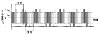
- FIG. 7A to 7D show application examples of lighting waveforms included in the technical scope of the present invention.
- FIG. 7A shows an application example of the lighting waveform in the secondary protrusion forming step.
- a pseudo-low-frequency lighting state is created using a boost current.
- the electric power to be input is biased to the + side due to the superposition of the boost current of the current value Ib three times with the normal lamp current of the current value In, and one of the low-frequency parts is The heat energy is applied to the electrode continuously for a certain period.
- the electric power to be input is biased to the negative side due to the superposition of the boost current of the current value Ib three times with the normal lamp current of the current value In, and one of the low frequency parts, as in the low frequency part.
- the heat energy is applied to the electrode continuously for a certain period.
- This state is assumed to be camouflaged low frequency periods CLT1 and CLT2 in which low frequency parts are artificially created. That is, it is possible to artificially create a state where low frequency lighting is performed while high frequency lighting is performed.
- the pseudo-low frequency part is created as described below.
- the secondary protrusion forming step since it is required to quickly form the secondary protrusions 22a and 22b, it is preferable to keep the frequency high.
- microprojections serving as seeds for the secondary projections 22a and 22b are formed at undesired locations other than the tips of the primary projections 21a and 21b, and it is desirable to eliminate such undesired microprojections. Therefore, by artificially creating a low-frequency part, the thermal diffusion region can be extended to the base side from the tip, and the minute protrusions formed at an undesired position can be melted and eliminated.
- FIG. 7B shows a lighting waveform obtained by further applying the lighting waveform of FIG. 7A.
- the camouflaged low frequency period CLT1 is a first camouflaged low frequency period CLT11 in which the boost current of the current value Ib is superimposed twice on the normal lamp current of the current value In. It can be said that there is.
- the camouflaged low frequency period CLT1 includes the first camouflaged low frequency period CLT11 seven times. The same applies to the camouflaged low frequency period CLT2. In this way, a plurality of camouflaged low frequency periods can be provided and adjusted to have various thermal diffusion lengths.
- FIG. 7C shows a lighting waveform obtained by further applying the lighting waveform of FIG. 7B.
- the lamp voltage may increase by constant power control, and the lamp current may be insufficient, and the thermal energy for forming the secondary protrusion may be insufficient.
- the shortage can be compensated by superimposing the boost current.
- the first camouflaged low frequency period CLT11 is used as shown in FIG. 7C.
- the waveform may be a mixture of low-frequency current components. This makes it possible to supplement the heat energy that is insufficient to form the secondary protrusions 22a and 22b.
- FIG. 7D is also a lighting waveform obtained by further applying the lighting waveform of FIG. 7B.
- thermal energy is ensured by intermittently superimposing low-frequency current components in cases where thermal energy cannot be ensured only by driving with a sufficiently short thermal diffusion length.
- a low-frequency current component may be appropriately inserted as a means for adjusting the heat energy to be input.
- a rectangular wave pulse having the same frequency as the high-frequency current component is boosted on the low-frequency rectangular wave pulse.
- the high-frequency property can be secured, and the growth of the secondary protrusions 22a and 22b can be secured to some extent.
- the low-frequency part may not necessarily be a strict low-frequency rectangular wave pulse, but may be a lighting waveform having a camouflaged low-frequency period in which a substantially low-frequency function can be obtained.
- FIG. 9A and 9B show still another application example of the lighting waveform in the secondary protrusion maintaining step.
- the lighting waveform in the high-frequency part, similarly to the lighting waveform shown in FIG. 4C, the lighting waveform is a secondary projection maintaining high-frequency alternating current SPMH made of a normal high-frequency rectangular wave pulse.
- FIG. 9B in the low frequency part to which the secondary protrusion maintaining low frequency alternating current SPML is supplied, the polarity of a part of the low frequency rectangular wave pulse that should normally be continuous is partially inverted.
- the lighting waveform has camouflaged low frequency periods CLT1 and CLT2 which are intermittent polarity inversions.
- FIG. 10 shows a configuration example of a discharge lamp lighting device according to an embodiment of the present invention.
- the discharge lamp lighting device includes a discharge lamp 10 and a power feeding device 30.
- the power feeding device 30 includes a step-down chopper circuit U1 to which a DC voltage is supplied, a full bridge circuit U2 connected to the output side of the step-down chopper circuit U1, and supplies the discharge lamp 10 with the DC voltage changed to an AC voltage;
- the starter circuit U3 is connected to the output side of the full bridge circuit U2 and the control unit 5.
- the control unit 5 can be configured by a processing device such as a microprocessor, for example, and its functional configuration is shown in a block diagram here.
- a step-down chopper circuit U1 includes a switching element Qx and a reactor Lx connected to a (+) side power supply terminal to which a DC voltage is supplied, a connection point between the switching element Qx and the reactor Lx, and a ( ⁇ ) side power supply terminal.
- a diode Dx having a cathode connected in between, a smoothing capacitor Cx connected to the output side of the reactor Lx, and a current detecting resistor Rx connected between the negative side terminal of the smoothing capacitor Cx and the anode side of the diode Dx Consists of Gx in FIG. 10 is a switching element driving circuit connected to the gate of the switching element Qx made of, for example, a field effect transistor.
- the input DC voltage Vdc is stepped down to a voltage corresponding to the duty.
- a voltage detection circuit Vx composed of a series circuit of resistors R1 and R2 is provided.
- the full bridge circuit U2 includes switching elements Q1 to Q4 connected in a bridge shape, switching element driving circuits G1 to G4 corresponding to the switching elements Q1 to Q4, and a driver 4 for operating the switching element driving circuits G1 to G4.
- the polarity inversion operation is performed according to the output drive signal.
- the starter circuit U3 includes a coil Lh and a capacitor Ch each connected in series to the discharge lamp 10.
- a capacitor Cp is connected between the input side of the coil Lh and the negative terminal of the capacitor Ch.
- the control of the output power to the discharge lamp 10 and the adjustment of the boost rate can be achieved by adjusting the operation duty of the switching element Qx of the step-down chopper circuit U1.
- the switching element Qx of the step-down chopper circuit U1 is turned on / off according to the duty of the gate signal Gx, and the power supplied to the discharge lamp 10 changes. That is, if the power is increased, the duty of the switching element Qx is increased, and if the power is decreased, the duty of the switching element Qx is decreased, etc., so that the lamp power value matches the input lighting power adjustment command signal SC. Take control. Further, at the time of boost, the duty of the switching element Qx is increased and the boost current is superimposed on the normal lamp current.
- the adjustment of the frequency of the alternating current supplied to the discharge lamp 10 is realized by adjusting the switching period of the switching elements Q1 to Q4 of the full bridge circuit U2.
- the controller 5 includes a drive signal generator 51 and a controller 52.
- the drive signal generator 51 is constituted by, for example, a processor.
- the controller 52 includes a lighting operation control unit 52a that controls the lighting operation of the discharge lamp 10, a drive signal selection unit 52b that controls the output of the drive signal generation unit 51, and a lighting power adjustment command signal SC from the outside.
- a power control unit 52c that drives the switching element Qx of the step-down chopper circuit U1 with a set duty and controls lamp power is provided.
- the power control unit 52c calculates the lamp power by obtaining the lamp current I L and the lamp voltage V L from the both-ends voltage of the current detection resistor Rx and the voltages detected by the voltage detection resistors R1 and R2, The duty of the switching element Qx of the step-down chopper circuit U1 is controlled so that the lamp power value matches the magnitude corresponding to the lighting power adjustment command signal SC. Further, the power control unit 52c determines whether the lighting power adjustment command signal SC corresponds to the lamp power value related to the steady lighting mode or the lamp power value related to the low power lighting mode, and determines the determination result. The signal is sent to the drive signal selector 52b.
- a lighting mode determination signal related to the low power lighting mode is transmitted to the drive signal selection unit 52b.
- the drive signal selection unit 52 b transmits a drive signal selection signal corresponding to the lighting mode determination signal to the drive signal generation unit 51.
- the drive signal selection unit 52b transmits a drive signal selection signal corresponding to the boost signal from the lighting operation control unit 52a to the drive signal generation unit 51 during boosting.
- the drive signal generator 51 generates a switching element drive signal according to the drive signal selection signal and transmits it to the driver 4.
- a switching element driving signal corresponding to the lighting mode of the discharge lamp 10 is output from the driving signal generator 51.
- a switching element drive signal corresponding to the boost signal from the lighting operation control unit 52a is output.
- the lighting operation control unit 52a of the controller 52 When the lighting command signal SL is given, power supply to the discharge lamp 10 is started, and the lighting operation control unit 52a of the controller 52 generates a starting circuit drive signal, and the starter circuit U3 lights the discharge lamp 10.
- the power control unit 52c calculates lamp power from the lamp voltage V L detected by the voltage detection resistors R1 and R2 and the lamp current I L detected by the resistor Rx.
- the power control unit 52c of the controller 52 controls the lamp power by controlling the switching element Qx of the step-down chopper circuit U1 based on the lighting power adjustment command signal SC and the calculated lamp power value.
- the switching element Qx of the step-down chopper circuit U1 changes according to the duty of the gate signal Gx.
- the duty of the switching element Qx is increased if the power is increased, and if the power is decreased.
- the gate signal Gx is controlled so that the lamp power value matches the input lighting power adjustment command signal SC by reducing the duty of the switching element Qx.
- the drive signal selection unit 52b of the controller 52 The signal generator 51 outputs a predetermined switching element drive signal corresponding to the steady lighting mode to drive the driver 4. Further, the power control unit 52c sets the output power for the discharge lamp 10 to the lamp power in the steady lighting mode according to the driving signal selection signal related to the steady lighting mode from the driving signal selection unit 52b. As a result, the full bridge circuit U2 performs a polarity inversion operation in accordance with the drive signal from the driver 4, and the discharge lamp 10 is lit with the lighting waveform in the steady lighting mode.
- the discharge lamp 10 is driven with a lighting waveform in which a low frequency part with a frequency of 5 to 200 Hz is inserted into a high frequency part with a fundamental frequency of 60 Hz to 1000 Hz.
- the lamp power value related to the lighting power adjustment command signal SC is small, that is, the lamp power value is 80% or less (practically 25 to 80%) of the rated power consumption.
- the drive signal selection unit 52 b of the controller 52 drives the driver 4 by causing the drive signal generation unit 51 to output a predetermined switching element drive signal corresponding to the low power lighting mode.
- the power control unit 52c sets the output power for the discharge lamp 10 to the lamp power in the low power lighting mode according to the driving signal selection signal related to the low power lighting mode from the driving signal selection unit 52b.
- the full bridge circuit U2 performs a polarity inversion operation according to the drive signal from the driver 4, and the discharge lamp 10 lights up with the lighting waveform of the low power lighting mode shown in FIGS. 4B and 4D, for example.
- the lighting operation control unit 52a When the lamp is lit in the low power lighting mode, the lighting operation control unit 52a outputs a boost signal at a predetermined cycle.
- the drive signal selection unit 52b outputs a drive signal selection signal corresponding to the boost signal, and the drive signal generation unit 51 outputs a switching element drive signal corresponding to the boost signal.
- the boost signal is also supplied to the power control unit 52c, and the power control unit 52c increases the duty of the switching element Qx of the step-down chopper circuit U1 according to the boost signal.
- the power control unit 52c boosts the output power to the discharge lamp 10 during the period in which the boost signal is output, and each time the boost signal is output, the discharge lamp 10 has the current value In of the normal lamp current.
- a lamp current I L on which the current value Ib of the boost current is superimposed is supplied.
- the discharge lamp is lit with the lighting waveform shown in FIG. 4A in the steady lighting mode, and the discharge lamp is lit with the lighting waveforms shown in FIGS. 4B and 4D in the low power lighting mode.
- the discharge lamp was lit with the lighting waveform shown in FIG. 11A, and in the low power lighting mode, the discharge lamp was lit with the lighting waveform shown in FIG. 11B.
- the frequency of the secondary projection forming alternating current (SPF) in the secondary projection forming step in the low power lighting mode is 1000 Hz, and the secondary in the secondary projection maintaining step.
- the frequency of the high frequency current for maintaining the protrusion (SPMH) was 720 Hz
- the frequency of the low frequency current for maintaining the secondary protrusion (SPML) was 120 Hz.
- the low power lighting mode is not divided into two steps, and a high frequency period (HT) by a rectangular wave pulse of a high frequency current of 740 Hz and a rectangular shape of a low frequency current of 92.5 Hz are always obtained.
- the discharge lamp was lit with a lighting waveform consisting of a low frequency period (LT) due to a wave pulse.
- the rated power consumption of the discharge lamp used for evaluation in both the example according to the present invention and the conventional example is 270 W, and the lamp power in the low power lighting mode is 63% of the rated power consumption, that is, 170 W. .
- the occurrence of flicker was determined by the illuminance fluctuation rate on the projection surface. Specifically, the illuminance is measured at 100 ms intervals using an illuminometer, and the illuminance fluctuation rate due to the maximum change amount is less than 2.0% (good), the case where it is less than 3.0% (Somewhat good), the case of 3.0% or more was marked as x (target not achieved). This is because when the illuminance fluctuation rate is 3.0% or more, it is visually recognized as flicker by human eyes.
- Table 3 The results are shown in Table 3 below.
- the present invention is divided into the steps of forming the secondary protrusion and maintaining the secondary protrusion in the low-power lighting mode, and by setting the lighting waveform optimized for each, the discharge lamp The problem of flicker that is likely to occur when the is turned on in the low power lighting mode can be solved.
Abstract
The objective of the present invention is to provide a discharge lamp lighting device capable of transitioning smoothly to a low-power lighting mode and preserving secondary protrusions over a long period of time. The discharge lamp lighting device is provided with a power-supply device for driving, switchably between a normal lighting mode and a low-power lighting mode, a discharge lamp equipped with electrodes, each having a protrusion formed at the tip. In the low-power lighting mode, the power-supply device controls the supply of power to the discharge lamp in such a way that, after a secondary protrusion forming process of supplying an alternating current having a frequency that is at the base frequency of the normal lighting mode or greater, a transition occurs to a secondary protrusion preserving process of supplying alternately a high-frequency alternating current having a frequency that is higher than the base frequency of the normal lighting mode and a low-frequency alternating current having a frequency that is lower than the high-frequency alternating current.
Description
本発明は、放電ランプ点灯装置に関し、特にランプ点灯時のランプ消費電力を定格消費電力の25~80%まで小さくしても、安定に点灯させることができる放電ランプ点灯装置に関するものである。
The present invention relates to a discharge lamp lighting device, and more particularly to a discharge lamp lighting device that can be stably lit even if the lamp power consumption during lamp lighting is reduced to 25 to 80% of the rated power consumption.
従来から、プロジェクタなどの画像形成装置の光源として、発光管の内部に水銀を0.20mg/mm3 以上封入した放電ランプを搭載した、放電ランプ点灯装置が知られている。例えば特許第469736号公報(特許文献1)がそれである。
この種の放電ランプ点灯装置が用いられているプロジェクタ装置では、定格消費電力よりもランプ消費電力を下げて使用するいわゆる「エコモード」を採用した装置が多くなってきており、特に最近は「スーパーエコモード」と呼ばれる、定格消費電力比で40~80%にまでランプ消費電力を抑えた小電力点灯機能を備えている。 Conventionally, as a light source for an image forming apparatus such as a projector, a discharge lamp lighting device is known in which a discharge lamp in which 0.20 mg / mm 3 or more of mercury is sealed in an arc tube is mounted. For example, Japanese Patent No. 469936 (Patent Document 1).
In projector devices using this type of discharge lamp lighting device, there are an increasing number of devices adopting a so-called “eco mode” in which the lamp power consumption is lower than the rated power consumption. It is equipped with a low-power lighting function called “eco-mode” that reduces lamp power consumption to 40-80% of the rated power consumption ratio.
このような小電力点灯モードでは、放電ランプに投入される電力が小さいため、電極先端での温度が低下し、アークが収縮することになる。これにより、アークの位置が不安定になりフリッカ現象を起こし易いという問題点がある。
In such a low power lighting mode, since the electric power supplied to the discharge lamp is small, the temperature at the electrode tip is lowered and the arc is contracted. As a result, there is a problem that the position of the arc becomes unstable and a flicker phenomenon is likely to occur.
このような問題点を解決するために特許文献1に記載の発明では、放電ランプの電極先端において、定常点灯時にアークを保持する一次突起とは別に、小電力点灯モードでのランプ点灯時(以下、「小電力点灯時」ともいう。)においてもアークを保持することができる二次突起を積極的に形成し、アークが細くなった状態でも、フリッカによるチラツキを低減することができる技術が開示されている。
In order to solve such a problem, in the invention described in Patent Document 1, at the electrode tip of the discharge lamp, the lamp is lit in the low-power lighting mode (hereinafter referred to as the primary protrusion that holds the arc at the time of steady lighting). In addition, a technique is disclosed in which a secondary protrusion capable of holding an arc is actively formed even during “low power lighting”, and flicker caused by flicker can be reduced even when the arc is thin. Has been.
従来の放電ランプ点灯装置では、図11Aに示すように、放電ランプが例えば定格消費電力で点灯される定常点灯時において、高周波の交流電流が供給される期間HTと、低周波の交流電流が供給される期間LTとを有する点灯波形で放電ランプを点灯している。放電ランプの点灯モードを小電力点灯モードに切換えた場合、図11Bに示すように、高周波の交流電流が供給される期間HTと、低周波の交流電流が供給される期間LTとを有する点灯波形において、低周波の交流電流の半サイクル時に電流値Bのブースト電流を当該低周波の交流電流の電流値Nに付加することで、積極的に二次突起を形成するというものである。
上記技術によれば、二次突起を形成することにより、小電力点灯モード(スーパーエコモード)においてもアークを安定的に維持することができる、とされている。 In the conventional discharge lamp lighting device, as shown in FIG. 11A, during steady lighting in which the discharge lamp is lit with, for example, rated power consumption, a period HT in which a high-frequency alternating current is supplied and a low-frequency alternating current are supplied. The discharge lamp is lit with a lighting waveform having a period LT. When the lighting mode of the discharge lamp is switched to the low power lighting mode, as shown in FIG. 11B, a lighting waveform having a period HT in which a high-frequency AC current is supplied and a period LT in which a low-frequency AC current is supplied. , The secondary protrusion is positively formed by adding the boost current of the current value B to the current value N of the low frequency alternating current during the half cycle of the low frequency alternating current.
According to the above technique, the arc can be stably maintained even in the low power lighting mode (super eco mode) by forming the secondary protrusion.
しかしながら、従来例の放電ランプ点灯装置では、小電力点灯モードの点灯波形において、二次突起の生成に寄与する点灯波形と、二次突起の維持に寄与する点灯波形とが混在していた。
そのため、二次突起の形成と二次突起の維持の個別の過程については必ずしも合理化されておらず、二次突起が成長するのに時間がかかり、また形成した二次突起を長時間維持することができなかった。 However, in the discharge lamp lighting device of the conventional example, the lighting waveform that contributes to the generation of the secondary protrusion and the lighting waveform that contributes to the maintenance of the secondary protrusion are mixed in the lighting waveform of the low power lighting mode.
Therefore, the individual processes of forming the secondary protrusion and maintaining the secondary protrusion are not necessarily rationalized, it takes time for the secondary protrusion to grow, and the formed secondary protrusion should be maintained for a long time. I could not.
上記の課題について本発明者らが検討した結果について簡単に説明すると、二次突起の形成に関しては、従来例の小電力点灯モードでの点灯波形における高周波の交流電流が供給される期間HTでは二次突起が成長していくが、低周波の交流電流が供給される期間LTでは必ずしも二次突起が成長し続けるわけではなく、温度上昇によって溶けて縮小したりもしていた。
かといって、高周波の交流電流のみを供給して放電ランプを点灯させると、二次突起が損耗しすぎて過剰に蒸発し黒化してしまう結果となった。 A brief description will be given of the results of the study by the present inventors regarding the above-described problem. Regarding the formation of the secondary protrusion, the secondary protrusion is formed in the period HT in which a high-frequency alternating current is supplied in the lighting waveform in the low power lighting mode of the conventional example. Although the secondary protrusions grow, the secondary protrusions do not always continue to grow during the period LT in which the low-frequency alternating current is supplied, and they melt and shrink as the temperature rises.
However, when only the high-frequency alternating current was supplied to light the discharge lamp, the secondary protrusions were excessively worn, resulting in excessive evaporation and blackening.
そこで、本発明では、小電力点灯モードへの移行を円滑に行い、二次突起を長時間の間維持することのできる放電ランプ点灯装置を提供することを目的とする。
Therefore, an object of the present invention is to provide a discharge lamp lighting device that can smoothly shift to the low power lighting mode and maintain the secondary protrusion for a long time.
上記課題を解決するために、本発明は、発光管内に、先端に突起が形成された一対の電極が2.0mm以下の間隔で対向配置されると共に、0.20mg/mm3 以上の水銀とハロゲンが封入された放電ランプと、この放電ランプに対して交流電流を供給する給電装置から構成される放電ランプ点灯装置において、
前記給電装置は、前記放電ランプを60Hz~1000Hzの範囲内から選択された基本周波数で点灯させる定常点灯モードと、前記放電ランプを当該放電ランプの定格消費電力に対して25~80%の範囲内の電力値で駆動する小電力点灯モードとを切り替え可能に駆動するものであって、
前記給電装置は、前記小電力点灯モードにおいては、
ランプ電力を低下させながら、200Hz~2000Hzの範囲内から選択された、前記定常点灯モードにおける基本周波数以上の周波数を有する二次突起形成用交流電流を供給する二次突起形成工程の後に、
当該定常点灯モードにおける基本周波数よりも周波数が高い100Hz~1500Hzの範囲から選択された周波数の二次突起維持用高周波電流、および当該二次突起維持用高周波電流よりも周波数が低い二次突起維持用低周波電流を二次突起維持用交流電流として交互に供給する二次突起維持工程に移行されるよう、
前記放電ランプに対する給電制御を行うことを特徴とする。
また、本発明では、前記二次突起形成用交流電流の周波数は、前記二次突起維持用高周波電流の周波数以上の大きさとしてもよい。
また、本発明では、前記二次突起維持工程における、前記二次突起維持用低周波電流の前記二次突起維持用高周波電流に対する時間的比率、又は点灯波形を、ランプ電力、ランプ電圧、若しくはランプ電流、又はこれらの合算パラメータに応じて変化させてもよい。
また、本発明では、前記二次突起形成工程においては、前記選択された周波数の通常ランプ電流に対して所定の時間的頻度でブースト電流を重畳した二次突起形成用交流電流を供給してもよい。
また、本発明では、前記二次突起維持工程においては、前記選択された周波数の通常ランプ電流に対して所定の時間的頻度でブースト電流を重畳した二次突起維持用交流電流を供給してもよい。
また、本発明では、前記ブースト電流の重畳比率、若しくは時間的頻度を、ランプ電力、ランプ電圧、若しくはランプ電流、又はこれらの合算パラメータに応じて変化させてもよい。
また、本発明では、前記ブースト電流の重畳比率を変化させるに際して、目標重畳比率に向けて段階的に重畳比率を変化させてもよい。 In order to solve the above-described problems, the present invention provides a light emitting tube in which a pair of electrodes having protrusions formed at the tip thereof are arranged to face each other at intervals of 2.0 mm or less, and 0.20 mg / mm 3 or more of mercury and In a discharge lamp lighting device composed of a discharge lamp in which halogen is enclosed and a power supply device that supplies an alternating current to the discharge lamp,
The power supply device includes a steady lighting mode for lighting the discharge lamp at a fundamental frequency selected from a range of 60 Hz to 1000 Hz, and a range of 25 to 80% of the discharge lamp with respect to a rated power consumption of the discharge lamp. The low power lighting mode that is driven with a power value of
In the low power lighting mode, the power supply device is
After the secondary protrusion forming step of supplying the secondary protrusion forming alternating current having a frequency equal to or higher than the fundamental frequency in the steady lighting mode, selected from the range of 200 Hz to 2000 Hz while reducing the lamp power,
A secondary projection maintaining high-frequency current having a frequency selected from a range of 100 Hz to 1500 Hz higher in frequency than the fundamental frequency in the steady lighting mode, and a secondary projection maintaining high-frequency current lower than the secondary projection maintaining high-frequency current In order to shift to the secondary projection maintaining step of alternately supplying the low frequency current as the secondary projection maintaining alternating current,
Power supply control for the discharge lamp is performed.
In the present invention, the frequency of the secondary protrusion-forming alternating current may be greater than or equal to the frequency of the secondary protrusion-maintaining high-frequency current.
Further, in the present invention, in the secondary protrusion maintaining step, the time ratio of the low frequency current for maintaining the secondary protrusion to the high frequency current for maintaining the secondary protrusion, or the lighting waveform is expressed as lamp power, lamp voltage, or lamp. You may change according to an electric current or these total parameters.
In the present invention, in the secondary protrusion forming step, a secondary protrusion forming alternating current in which a boost current is superimposed on the normal lamp current of the selected frequency at a predetermined time frequency may be supplied. Good.
In the present invention, in the secondary protrusion maintaining step, the secondary protrusion maintaining AC current in which the boost current is superimposed on the normal lamp current of the selected frequency at a predetermined time frequency may be supplied. Good.
In the present invention, the superposition ratio or time frequency of the boost current may be changed according to the lamp power, the lamp voltage, the lamp current, or their combined parameters.
In the present invention, when the boost current superposition ratio is changed, the superposition ratio may be changed stepwise toward the target superposition ratio.
本発明によれば、小電力点灯モードを、新たに二次突起形成工程と、二次突起維持工程という2つの工程に分け、従来はまとめて小電力点灯モードとしていた点灯波形を、それぞれに適した点灯波形とすることにより、小電力点灯モードへの移行を円滑に行い、長時間二次突起を維持することができ、ランプ消費電力の節約および放電ランプの長寿命化を達成することができる。
According to the present invention, the low-power lighting mode is newly divided into two processes, a secondary protrusion forming process and a secondary protrusion maintaining process. By using the lighting waveform, it is possible to smoothly shift to the low power lighting mode, maintain the secondary protrusion for a long time, and save the lamp power consumption and extend the life of the discharge lamp. .
図1は本発明の実施形態に係る放電ランプの構成を示す図、図2は図1に示す放電ランプの電極の構成例を示す図である。
図1に示すように、放電ランプ10の発光管は石英ガラスからなり、略楕円球形の発光部11とその両端に連設されたロッド状の封止管部12とを備えている。
発光部11の内部にはタングステンよりなる一対の電極20a,20bが、電極間距離が2mm以下の間隔で対向配置されている。電極20a,20bは、図2に示すように、一次突起21a、21bを先端に有し、小電力点灯モードでのランプ点灯時においては、一次突起21a、21bの先端にさらに二次突起22a、22bが形成された形態とされる。
なお、この実施形態にかかる放電ランプ10は、定常点灯モードでは交流点灯方式で点灯されるものであり、電極20a,20bの構成は、定常点灯モードでのランプ点灯時における熱的設計を容易にする目的で、すべて同一の構成とされている。
発光管の両端に位置する封止管部12の各々の内部にはモリブデンよりなる帯状の金属箔13が埋設されている。この金属箔13の発光部11側の端部には電極20a,20bの軸部202、202が接続されており、他方の端部には外部リード棒14、14が接続されている。 FIG. 1 is a diagram showing a configuration of a discharge lamp according to an embodiment of the present invention, and FIG. 2 is a diagram showing a configuration example of electrodes of the discharge lamp shown in FIG.
As shown in FIG. 1, the arc tube of thedischarge lamp 10 is made of quartz glass, and includes a substantially elliptical light-emitting portion 11 and rod-shaped sealing tube portions 12 connected to both ends thereof.
Inside thelight emitting portion 11, a pair of electrodes 20a and 20b made of tungsten are arranged opposite to each other with an interelectrode distance of 2 mm or less. As shown in FIG. 2, the electrodes 20a and 20b have primary protrusions 21a and 21b at the tips. When the lamp is lit in the low power lighting mode, the secondary protrusions 22a and 22a are further provided at the tips of the primary protrusions 21a and 21b. 22b is formed.
Thedischarge lamp 10 according to this embodiment is lit in an alternating lighting mode in the steady lighting mode, and the configuration of the electrodes 20a and 20b facilitates thermal design during lamp lighting in the steady lighting mode. For this purpose, all have the same configuration.
A strip-shapedmetal foil 13 made of molybdenum is embedded in each of the sealing tube portions 12 located at both ends of the arc tube. The shaft portions 202 and 202 of the electrodes 20a and 20b are connected to the end portion of the metal foil 13 on the light emitting portion 11 side, and the external lead rods 14 and 14 are connected to the other end portion.
図1に示すように、放電ランプ10の発光管は石英ガラスからなり、略楕円球形の発光部11とその両端に連設されたロッド状の封止管部12とを備えている。
発光部11の内部にはタングステンよりなる一対の電極20a,20bが、電極間距離が2mm以下の間隔で対向配置されている。電極20a,20bは、図2に示すように、一次突起21a、21bを先端に有し、小電力点灯モードでのランプ点灯時においては、一次突起21a、21bの先端にさらに二次突起22a、22bが形成された形態とされる。
なお、この実施形態にかかる放電ランプ10は、定常点灯モードでは交流点灯方式で点灯されるものであり、電極20a,20bの構成は、定常点灯モードでのランプ点灯時における熱的設計を容易にする目的で、すべて同一の構成とされている。
発光管の両端に位置する封止管部12の各々の内部にはモリブデンよりなる帯状の金属箔13が埋設されている。この金属箔13の発光部11側の端部には電極20a,20bの軸部202、202が接続されており、他方の端部には外部リード棒14、14が接続されている。 FIG. 1 is a diagram showing a configuration of a discharge lamp according to an embodiment of the present invention, and FIG. 2 is a diagram showing a configuration example of electrodes of the discharge lamp shown in FIG.
As shown in FIG. 1, the arc tube of the
Inside the
The
A strip-shaped
発光管部12の内部には、放電媒体としての水銀と、希ガスと、ハロゲンガスが封入され、発光空間Sが形成される。
水銀は、必要な可視光波長、例えば、波長360~780nmという放射光を得るためのものであり、0.15mg/mm3 以上封入されている。この封入量は、温度条件によっても異なるが、ランプ点灯時に150気圧以上という極めて高い水銀蒸気圧を得るためのものである。また、水銀を0.20mg/mm3 以上封入することでランプ点灯時に200気圧以上、あるいは300気圧以上という高い水銀蒸気圧が得られる放電ランプを作ることができ、水銀蒸気圧が高くなるほどプロジェクタ装置に適した光源を実現することができる。
希ガスは、静圧で約10~26kPa封入される。希ガスとしては、例えばアルゴンガスが用いられる。このように希ガスを封入する理由は、点灯始動性を改善するためである。
また、ハロゲンは、沃素、臭素、塩素などが水銀その他の金属との化合物の形態で封入される。ハロゲンの封入量は、10-6 ~10-2 μmol/mm3 の範囲から選択される。
ハロゲンの機能は、ハロゲンサイクルを利用した長寿命化(黒化防止)もあるが、本発明の放電ランプ10のように極めて小型で高い水銀蒸気圧を有するものの場合、発光管の失透防止である。なお、発光空間Sには、更に他の放電媒体としてハロゲン化金属を封入することもできる。 Inside thearc tube 12, mercury as a discharge medium, a rare gas, and a halogen gas are sealed, and a light emission space S is formed.
Mercury is used to obtain a necessary visible light wavelength, for example, a radiated light having a wavelength of 360 to 780 nm, and is contained in an amount of 0.15 mg / mm 3 or more. Although the amount of sealing varies depending on temperature conditions, it is for obtaining an extremely high mercury vapor pressure of 150 atm or more when the lamp is turned on. In addition, a discharge lamp capable of obtaining a high mercury vapor pressure of 200 atm or higher or 300 atm or higher when the lamp is lit can be produced by enclosing 0.20 mg / mm 3 or more of mercury, and the projector device increases as the mercury vapor pressure increases. Can be realized.
The rare gas is sealed at about 10 to 26 kPa at static pressure. For example, argon gas is used as the rare gas. The reason for sealing the rare gas in this way is to improve the lighting startability.
Halogen is enclosed in the form of a compound of iodine, bromine, chlorine or the like with mercury or another metal. The enclosed amount of halogen is selected from the range of 10 −6 to 10 −2 μmol / mm 3 .
The function of the halogen is to prolong the life (prevent blackening) using the halogen cycle, but in the case of an extremely small and high mercury vapor pressure like thedischarge lamp 10 of the present invention, it prevents the devitrification of the arc tube. is there. The light emitting space S can be filled with a metal halide as another discharge medium.
水銀は、必要な可視光波長、例えば、波長360~780nmという放射光を得るためのものであり、0.15mg/mm3 以上封入されている。この封入量は、温度条件によっても異なるが、ランプ点灯時に150気圧以上という極めて高い水銀蒸気圧を得るためのものである。また、水銀を0.20mg/mm3 以上封入することでランプ点灯時に200気圧以上、あるいは300気圧以上という高い水銀蒸気圧が得られる放電ランプを作ることができ、水銀蒸気圧が高くなるほどプロジェクタ装置に適した光源を実現することができる。
希ガスは、静圧で約10~26kPa封入される。希ガスとしては、例えばアルゴンガスが用いられる。このように希ガスを封入する理由は、点灯始動性を改善するためである。
また、ハロゲンは、沃素、臭素、塩素などが水銀その他の金属との化合物の形態で封入される。ハロゲンの封入量は、10-6 ~10-2 μmol/mm3 の範囲から選択される。
ハロゲンの機能は、ハロゲンサイクルを利用した長寿命化(黒化防止)もあるが、本発明の放電ランプ10のように極めて小型で高い水銀蒸気圧を有するものの場合、発光管の失透防止である。なお、発光空間Sには、更に他の放電媒体としてハロゲン化金属を封入することもできる。 Inside the
Mercury is used to obtain a necessary visible light wavelength, for example, a radiated light having a wavelength of 360 to 780 nm, and is contained in an amount of 0.15 mg / mm 3 or more. Although the amount of sealing varies depending on temperature conditions, it is for obtaining an extremely high mercury vapor pressure of 150 atm or more when the lamp is turned on. In addition, a discharge lamp capable of obtaining a high mercury vapor pressure of 200 atm or higher or 300 atm or higher when the lamp is lit can be produced by enclosing 0.20 mg / mm 3 or more of mercury, and the projector device increases as the mercury vapor pressure increases. Can be realized.
The rare gas is sealed at about 10 to 26 kPa at static pressure. For example, argon gas is used as the rare gas. The reason for sealing the rare gas in this way is to improve the lighting startability.
Halogen is enclosed in the form of a compound of iodine, bromine, chlorine or the like with mercury or another metal. The enclosed amount of halogen is selected from the range of 10 −6 to 10 −2 μmol / mm 3 .
The function of the halogen is to prolong the life (prevent blackening) using the halogen cycle, but in the case of an extremely small and high mercury vapor pressure like the
このような放電ランプ10について具体的数値例を示すと、例えば、発光部11の最大外径が10mm、電極間距離が0.7mm、発光部11の内容積が80mm3 、定格電圧が65V、定格消費電力が270Wである。この放電ランプ10は、交流方式で点灯される。
また、この種の放電ランプは、小型化するプロジェクタ装置に内蔵されるものであり、装置の全体寸法が極めて小型化される一方で高い光量が要求されることから、発光部11内の熱的条件は極めて厳しいものとなる。例えば、放電ランプの管壁負荷値は1.5~3.5W/mm2 、具体的には2.9W/mm2 となる。このような高い水銀蒸気圧や管壁負荷を有することにより、プロジェクタ装置等のプレゼンテーション用機器に搭載された場合に演色性の良い放射光を提供することができる。 Specific examples of numerical values for such adischarge lamp 10 include, for example, a maximum outer diameter of the light emitting portion 11 of 10 mm, a distance between the electrodes of 0.7 mm, an inner volume of the light emitting portion 11 of 80 mm 3 , a rated voltage of 65 V, The rated power consumption is 270W. The discharge lamp 10 is lit by an alternating current method.
In addition, this type of discharge lamp is built in a projector device that is miniaturized, and since the overall size of the device is extremely miniaturized, a high amount of light is required. Conditions are extremely severe. For example, the wall load value of the discharge lamp 1.5 ~ 3.5W / mm 2, a 2.9W / mm 2 in particular. By having such a high mercury vapor pressure and tube wall load, it is possible to provide radiant light with good color rendering when mounted on a presentation device such as a projector device.
また、この種の放電ランプは、小型化するプロジェクタ装置に内蔵されるものであり、装置の全体寸法が極めて小型化される一方で高い光量が要求されることから、発光部11内の熱的条件は極めて厳しいものとなる。例えば、放電ランプの管壁負荷値は1.5~3.5W/mm2 、具体的には2.9W/mm2 となる。このような高い水銀蒸気圧や管壁負荷を有することにより、プロジェクタ装置等のプレゼンテーション用機器に搭載された場合に演色性の良い放射光を提供することができる。 Specific examples of numerical values for such a
In addition, this type of discharge lamp is built in a projector device that is miniaturized, and since the overall size of the device is extremely miniaturized, a high amount of light is required. Conditions are extremely severe. For example, the wall load value of the discharge lamp 1.5 ~ 3.5W / mm 2, a 2.9W / mm 2 in particular. By having such a high mercury vapor pressure and tube wall load, it is possible to provide radiant light with good color rendering when mounted on a presentation device such as a projector device.
本発明において、定格消費電力に対し平均して25~80%の電力値で動作されるモードを「小電力点灯モード」という。また、定格消費電力に対し平均して80%より大きい電力値で動作されるモードを「定常点灯モード」といい、特に、定格消費電力で動作されるモードを「定格点灯モード」という。
定格消費電力の25~80%という小さいランプ電力値の範囲で放電ランプ10を点灯する場合、後述の点灯条件を採用することにより、二次突起22a,22bの成長を円滑にし、かつ、二次突起22a,22bの形状を長期間維持することができるので、安定的に点灯することができるとともに、電極20a,20bの摩耗を防ぐことができる。 In the present invention, a mode in which an average power value of 25 to 80% of the rated power consumption is operated is referred to as a “low power lighting mode”. In addition, a mode that is operated at a power value that is greater than 80% on average with respect to the rated power consumption is referred to as a “steady lighting mode”, and a mode that is operated at the rated power consumption is particularly referred to as a “rated lighting mode”.
When thedischarge lamp 10 is lit in the range of the lamp power value as small as 25 to 80% of the rated power consumption, the growth of the secondary protrusions 22a and 22b is facilitated by adopting the lighting conditions described later, and the secondary lamp Since the shape of the protrusions 22a and 22b can be maintained for a long period of time, it can be lit stably and wear of the electrodes 20a and 20b can be prevented.
定格消費電力の25~80%という小さいランプ電力値の範囲で放電ランプ10を点灯する場合、後述の点灯条件を採用することにより、二次突起22a,22bの成長を円滑にし、かつ、二次突起22a,22bの形状を長期間維持することができるので、安定的に点灯することができるとともに、電極20a,20bの摩耗を防ぐことができる。 In the present invention, a mode in which an average power value of 25 to 80% of the rated power consumption is operated is referred to as a “low power lighting mode”. In addition, a mode that is operated at a power value that is greater than 80% on average with respect to the rated power consumption is referred to as a “steady lighting mode”, and a mode that is operated at the rated power consumption is particularly referred to as a “rated lighting mode”.
When the
図3を用いて、本発明の点灯モードの切り替えについて説明する。
図3において、横軸が時間、縦軸が定格消費電力を100%とする、ランプ電力の定格消費電力に対する比率となっている。
放電ランプ10を点灯させてから時間T1が経過するまでの間は、放電ランプ10は、定格消費電力に対し100%の電力値で点灯されている。すなわち、この期間は定常点灯モード、具体的には定格点灯モードである。時間T1が経過した時点において、プロジェクタなどの外部の制御部から、本点灯装置の制御部に対して点灯電力調整指令信号が送信されると、これを受けて、定常点灯モードRMから、小電力点灯モードEMへと点灯モードが切り替わる。 The switching of the lighting mode according to the present invention will be described with reference to FIG.
In FIG. 3, the horizontal axis represents time, and the vertical axis represents the ratio of lamp power to rated power consumption, where the rated power consumption is 100%.
From the time when thedischarge lamp 10 is turned on until the time T1 elapses, the discharge lamp 10 is turned on at a power value of 100% of the rated power consumption. That is, this period is a steady lighting mode, specifically a rated lighting mode. When the lighting power adjustment command signal is transmitted from an external control unit such as a projector to the control unit of the present lighting device at the time when the time T1 has elapsed, in response to this, a low power is output from the steady lighting mode RM. The lighting mode is switched to the lighting mode EM.
図3において、横軸が時間、縦軸が定格消費電力を100%とする、ランプ電力の定格消費電力に対する比率となっている。
放電ランプ10を点灯させてから時間T1が経過するまでの間は、放電ランプ10は、定格消費電力に対し100%の電力値で点灯されている。すなわち、この期間は定常点灯モード、具体的には定格点灯モードである。時間T1が経過した時点において、プロジェクタなどの外部の制御部から、本点灯装置の制御部に対して点灯電力調整指令信号が送信されると、これを受けて、定常点灯モードRMから、小電力点灯モードEMへと点灯モードが切り替わる。 The switching of the lighting mode according to the present invention will be described with reference to FIG.
In FIG. 3, the horizontal axis represents time, and the vertical axis represents the ratio of lamp power to rated power consumption, where the rated power consumption is 100%.
From the time when the
小電力点灯モードEMでは、まず二次突起形成工程S1を行うことにより、一次突起21a,21bの先端に二次突起22a,22bを生成する。この際、ランプ電力は一次突起21a,21bのみでもフリッカが生じない大きさ(一次突起フリッカ安定電力)まで一旦低下させる予備調光を行うと、二次突起形成工程S1に移った際に、明るさの差によるちらつきが生じにくく好ましい。この例における一次突起フリッカ安定電力は、定格消費電力の例えば80%の大きさである。なお、この予備調光は行わなくても良い。
In the low power lighting mode EM, the secondary protrusions 22a and 22b are generated at the tips of the primary protrusions 21a and 21b by first performing the secondary protrusion forming step S1. At this time, if preliminary dimming is performed in which the lamp power is once reduced to such a level that the flicker does not occur even when only the primary protrusions 21a and 21b are generated (primary protrusion flicker stable power), the brightness is increased when the process proceeds to the secondary protrusion forming step S1. Flickering due to the difference in thickness is less likely to occur, which is preferable. The primary projection flicker stable power in this example is, for example, 80% of the rated power consumption. Note that this preliminary dimming need not be performed.
二次突起形成工程S1では、ランプ電力を下げながら素早く二次突起22a,22bを形成していく。この際に、ランプ電力を段階的に下げながら二次突起22a,22bを形成していくと、電力の差による明るさの差がちらつきとならず好適である。
In the secondary protrusion forming step S1, the secondary protrusions 22a and 22b are formed quickly while lowering the lamp power. At this time, if the secondary protrusions 22a and 22b are formed while the lamp power is lowered stepwise, it is preferable that the difference in brightness due to the difference in power does not flicker.
時間T2が経過した時点において二次突起22a,22bが形成されたら、二次突起維持工程S2に移る。
二次突起維持工程S2に移るタイミング、すなわち二次突起22a,22bが所望の形状に形成されたタイミングについては、種々の手段によって決定することができる。具体的には、実験に基づきT1からT2までの最も好ましい期間について求め、タイマー等によってこの期間を設定してもいいし、ランプ電流、ランプ電圧、もしくはランプ電力、またはこれらの合算パラメータによってタイミングを決定してもよい。 If the secondary protrusions 22a and 22b are formed when the time T2 has elapsed, the process proceeds to the secondary protrusion maintaining step S2.
The timing of moving to the secondary projection maintaining step S2, that is, the timing at which the secondary projections 22a and 22b are formed in a desired shape can be determined by various means. Specifically, the most preferable period from T1 to T2 is obtained based on experiments, and this period may be set by a timer or the like, or the timing may be set by lamp current, lamp voltage, lamp power, or a sum of these parameters. You may decide.
二次突起維持工程S2に移るタイミング、すなわち二次突起22a,22bが所望の形状に形成されたタイミングについては、種々の手段によって決定することができる。具体的には、実験に基づきT1からT2までの最も好ましい期間について求め、タイマー等によってこの期間を設定してもいいし、ランプ電流、ランプ電圧、もしくはランプ電力、またはこれらの合算パラメータによってタイミングを決定してもよい。 If the
The timing of moving to the secondary projection maintaining step S2, that is, the timing at which the
時間T2が経過した後は、小電力点灯モードEMの目標設定電力に到達し、二次突起維持工程S2が行われる。以後、小電力点灯モードEMが指示されている限り、二次突起維持工程における点灯波形での点灯が継続される。この例における目標設定電力は、例えば定格消費電力の65%の大きさである。
After the time T2 has elapsed, the target power setting of the low power lighting mode EM is reached, and the secondary protrusion maintaining step S2 is performed. Thereafter, as long as the low power lighting mode EM is instructed, lighting with the lighting waveform in the secondary protrusion maintaining process is continued. The target set power in this example is, for example, 65% of the rated power consumption.
以下、具体的に二次突起形成工程S1、および二次突起維持工程S2での点灯波形について説明する。図4A、図4Bおよび図4Dは本発明の実施形態1に係る点灯波形の一例を示す説明図である。以降、点灯波形は縦軸をランプ電流IL による電流値、横軸を時間とする、極性反転する矩形波パルスの交流電流波形を用いて説明する。
図4Aは、定格点灯モードの点灯波形の一例を示す説明図である。この点灯波形は、60~1000Hzの範囲内から選択された高周波の基本周波数で極性反転する高周波交流電流が供給される期間(以下、「高周波パート」ともいう。)RHTと、5~200の範囲内から選択された、基本周波数よりも低い周波数で極性反転する低周波交流電流が供給される期間(以下、「低周波パート」ともいう。)RLTとによるサイクルの組合せで成立している。なお、低周波パートRLTは、基本周波数どおりに極性判定しないことによって生成されている。この例における高周波交流電流の基本周波数は、例えば370Hzであり、低周波交流電流の周波数は、例えば30Hzである。 Hereinafter, the lighting waveforms in the secondary protrusion forming step S1 and the secondary protrusion maintaining step S2 will be specifically described. 4A, 4B, and 4D are explanatory diagrams illustrating examples of lighting waveforms according to the first embodiment of the present invention. Thereafter, the lighting waveform current value on the vertical axis by the lamp current I L, and the horizontal axis represents time, will be described with reference to alternating current waveform of the rectangular wave pulse to the polarity inversion.
FIG. 4A is an explanatory diagram illustrating an example of a lighting waveform in the rated lighting mode. This lighting waveform is a period (hereinafter also referred to as “high-frequency part”) RHT in which polarity is inverted at a high-frequency fundamental frequency selected from the range of 60 to 1000 Hz, and a range of 5 to 200 It is established by a combination of cycles based on a period (hereinafter also referred to as “low frequency part”) RLT in which a low frequency alternating current whose polarity is inverted at a frequency lower than the fundamental frequency is selected. The low frequency part RLT is generated by not determining the polarity according to the fundamental frequency. In this example, the basic frequency of the high-frequency alternating current is 370 Hz, for example, and the frequency of the low-frequency alternating current is 30 Hz, for example.
これに対し、図4Bは、小電力点灯モードの二次突起形成工程における点灯波形である。二次突起形成工程S1において供給される二次突起形成用交流電流SPFは、定常点灯モードにおける交流電流と同じく極性反転する高周波交流電流である。二次突起形成用交流電流SPFは、例えば200~2000Hzの範囲内から選択された、定常点灯モードRMにおける基本周波数よりも高い周波数を有する。この例における二次突起形成用交流電流SPFの周波数は、例えば1000Hzである。
このように周波数を高くする理由は、交流点灯において電極20a,20bの一次突起21a,21bの先端から根元側に向かって加わる熱の範囲の長さ、すなわち熱拡散長を短くして、一次突起21a,21bの先端のみに効率よく熱を伝えて素早く二次突起22a,22bを形成するためである。
二次突起形成用交流電流SPFの周波数は、所定の熱拡散長、および温度変化を設定する観点から、500~1500Hzであることがより好ましく、また600~1100Hzであることがさらに好ましい。 On the other hand, FIG. 4B is a lighting waveform in the secondary protrusion forming process in the low power lighting mode. The secondary protrusion-forming AC current SPF supplied in the secondary protrusion forming step S1 is a high-frequency alternating current that reverses its polarity as the alternating current in the steady lighting mode. The secondary protrusion forming AC current SPF has a frequency higher than the fundamental frequency in the steady lighting mode RM, for example, selected from the range of 200 to 2000 Hz. The frequency of the secondary protrusion forming alternating current SPF in this example is, for example, 1000 Hz.
The reason for increasing the frequency in this way is to shorten the length of the range of heat applied from the tips of the primary projections 21a, 21b of the electrodes 20a, 20b toward the root side in AC lighting, that is, the heat diffusion length, thereby reducing the primary projections. This is because the secondary projections 22a and 22b can be quickly formed by efficiently transferring heat only to the tips of 21a and 21b.
The frequency of the secondary protrusion forming AC current SPF is more preferably 500 to 1500 Hz, and further preferably 600 to 1100 Hz, from the viewpoint of setting a predetermined thermal diffusion length and temperature change.
このように周波数を高くする理由は、交流点灯において電極20a,20bの一次突起21a,21bの先端から根元側に向かって加わる熱の範囲の長さ、すなわち熱拡散長を短くして、一次突起21a,21bの先端のみに効率よく熱を伝えて素早く二次突起22a,22bを形成するためである。
二次突起形成用交流電流SPFの周波数は、所定の熱拡散長、および温度変化を設定する観点から、500~1500Hzであることがより好ましく、また600~1100Hzであることがさらに好ましい。 On the other hand, FIG. 4B is a lighting waveform in the secondary protrusion forming process in the low power lighting mode. The secondary protrusion-forming AC current SPF supplied in the secondary protrusion forming step S1 is a high-frequency alternating current that reverses its polarity as the alternating current in the steady lighting mode. The secondary protrusion forming AC current SPF has a frequency higher than the fundamental frequency in the steady lighting mode RM, for example, selected from the range of 200 to 2000 Hz. The frequency of the secondary protrusion forming alternating current SPF in this example is, for example, 1000 Hz.
The reason for increasing the frequency in this way is to shorten the length of the range of heat applied from the tips of the
The frequency of the secondary protrusion forming AC current SPF is more preferably 500 to 1500 Hz, and further preferably 600 to 1100 Hz, from the viewpoint of setting a predetermined thermal diffusion length and temperature change.
このような点灯波形とすることで、図4Cに示すように、電極20aの先端に位置する一次突起21aのさらに限られた領域(図4Cにおいて便宜上斜線を付した領域)に効率よく熱が伝わり、一次突起21aの先端より二次突起22aが突出するように形成される。
By using such a lighting waveform, as shown in FIG. 4C, heat is efficiently transmitted to a further limited region (region hatched for convenience in FIG. 4C) of the primary protrusion 21a located at the tip of the electrode 20a. The secondary protrusion 22a protrudes from the tip of the primary protrusion 21a.
次に、小電力点灯モードEMにおける、二次突起維持工程S2について説明する。
図4Dは、二次突起維持工程における点灯波形の一例である。二次突起維持工程S2においては、二次突起維持用高周波電流SPMHと二次突起維持用低周波電流SPMLが、二次突起維持用交流電流SPMとして供給される。
この点灯波形は、二次突起形成工程S1に係る点灯波形と同じように、二次突起維持用高周波電流SPMHが供給される期間(高周波パート)MHTと、二次突起維持用低周波電流SPMLが供給される期間(低周波パート)MLTとによるサイクルの組合せで成立している。二次突起維持用高周波電流SPMHは、100Hz~1500Hzの範囲内から選択された、定常点灯モード例えば定格点灯モードRMにおける基本周波数よりも高い周波数を有する。二次突起維持用低周波電流SPMLは、二次突起維持用高周波電流SPMHよりも低い周波数を有する。 Next, the secondary protrusion maintaining step S2 in the low power lighting mode EM will be described.
FIG. 4D is an example of a lighting waveform in the secondary protrusion maintaining step. In the secondary protrusion maintaining step S2, the secondary protrusion maintaining high frequency current SPMH and the secondary protrusion maintaining low frequency current SPML are supplied as the secondary protrusion maintaining AC current SPM.
This lighting waveform is similar to the lighting waveform related to the secondary protrusion forming step S1 in that the period (high frequency part) MHT in which the secondary protrusion maintaining high-frequency current SPMH is supplied and the secondary protrusion maintaining low-frequency current SPML are It is established by a combination of cycles according to the supplied period (low frequency part) MLT. The secondary projection maintaining high-frequency current SPMH has a frequency higher than the fundamental frequency in the steady lighting mode, for example, the rated lighting mode RM, selected from the range of 100 Hz to 1500 Hz. The secondary projection maintaining low frequency current SPML has a lower frequency than the secondary projection maintaining high frequency current SPMH.
二次突起維持用低周波電流SPMLは、簡単にいえば二次突起22aをあえて計画的に潰す電流である。
もし二次突起維持工程S2においても、前段の二次突起形成用交流電流SPFでの点灯をそのまま続けたとするならば、二次突起22a,22bの成長が過剰になってしまい、電極材料であるタングステンのアーク熱による蒸発等による損耗が激しくなる。これにより、ハロゲンサイクルでタングステンが電極20a,20bに帰還する際に、一次突起21a,21bの先端ではない不所望な位置に帰還したり、損耗によって一次突起21a,21b自体のタングステン量が減少したりする。 In short, the secondary projection maintaining low-frequency current SPML is a current that intentionally collapses thesecondary projection 22a.
Even in the secondary protrusion maintaining step S2, if lighting with the secondary protrusion forming AC current SPF is continued as it is, the growth of the secondary protrusions 22a and 22b becomes excessive, which is an electrode material. Wear due to evaporation of tungsten due to arc heat becomes severe. Thereby, when tungsten returns to the electrodes 20a and 20b in the halogen cycle, it returns to an undesired position other than the tips of the primary protrusions 21a and 21b, or the tungsten amount of the primary protrusions 21a and 21b itself decreases due to wear. Or
もし二次突起維持工程S2においても、前段の二次突起形成用交流電流SPFでの点灯をそのまま続けたとするならば、二次突起22a,22bの成長が過剰になってしまい、電極材料であるタングステンのアーク熱による蒸発等による損耗が激しくなる。これにより、ハロゲンサイクルでタングステンが電極20a,20bに帰還する際に、一次突起21a,21bの先端ではない不所望な位置に帰還したり、損耗によって一次突起21a,21b自体のタングステン量が減少したりする。 In short, the secondary projection maintaining low-frequency current SPML is a current that intentionally collapses the
Even in the secondary protrusion maintaining step S2, if lighting with the secondary protrusion forming AC current SPF is continued as it is, the growth of the
そこで、二次突起22a,22bが成長しすぎないように、成長を抑制するために二次突起22a,22bを溶融させて小さくする。具体的には、低周波パートMLTにおいて、一方の電極にのみ比較的長期間熱エネルギーが投入されることによって、二次突起22a,22bの先端が溶けて消失するものと推測される。
また、それだけではなく、低周波パートMLTでは熱拡散長が長いので、根元側である一次突起21a,21bに投入される熱エネルギーも増加し、一次突起21a,21bが温度上昇することによって、次の二次突起22a,22bが形成されやすくなる。
このように、低周波パートMLTにおいては、二次突起22a,22bの成長を抑制しつつ、次の二次突起22a,22bの成長の準備をしているのであって、単に二次突起22a,22bを潰しているというわけではない。 Therefore, in order to prevent the secondary protrusions 22a and 22b from growing too much, the secondary protrusions 22a and 22b are melted and made small in order to suppress the growth. Specifically, in the low frequency part MLT, it is presumed that the tips of the secondary protrusions 22a and 22b are melted and disappeared by applying thermal energy to only one electrode for a relatively long period of time.
In addition, since the thermal diffusion length is long in the low-frequency part MLT, the thermal energy input to the primary projections 21a and 21b on the root side also increases, and the temperature of the primary projections 21a and 21b increases. Secondary protrusions 22a and 22b are easily formed.
In this way, in the low frequency part MLT, preparation for growth of the next secondary protrusions 22a and 22b is made while suppressing the growth of the secondary protrusions 22a and 22b. It does not mean that 22b is being crushed.
また、それだけではなく、低周波パートMLTでは熱拡散長が長いので、根元側である一次突起21a,21bに投入される熱エネルギーも増加し、一次突起21a,21bが温度上昇することによって、次の二次突起22a,22bが形成されやすくなる。
このように、低周波パートMLTにおいては、二次突起22a,22bの成長を抑制しつつ、次の二次突起22a,22bの成長の準備をしているのであって、単に二次突起22a,22bを潰しているというわけではない。 Therefore, in order to prevent the
In addition, since the thermal diffusion length is long in the low-frequency part MLT, the thermal energy input to the
In this way, in the low frequency part MLT, preparation for growth of the next
しかし、二次突起22a,22bの成長を抑制しているのみでは、二次突起22a,22b自体が消失してしまうので、ある程度二次突起22a,22bを成長させるフェーズが必要となる。それが、二次突起維持用高周波電流SPMHが供給される高周波パートである。
二次突起維持用高周波電流SPMHは、簡単に言うと、二次突起22a,22bをほどほどに成長させるものである。そのためには、熱拡散長を短く、すなわち定常点灯モードにおける基本周波数よりも高い周波数とする必要がある。なお、二次突起22a,22bを過剰に成長させないために、二次突起維持用高周波電流SPMHの周波数を、二次突起形成用交流電流SPFの周波数以下にしてもよい。すなわち、二次突起維持用高周波電流SPMHの役割は、二次突起形成用交流電流SPFと類似しているといえる。 However, since the secondary protrusions 22a and 22b themselves disappear only by suppressing the growth of the secondary protrusions 22a and 22b, a phase for growing the secondary protrusions 22a and 22b to some extent is required. That is the high frequency part to which the secondary protrusion maintaining high frequency current SPMH is supplied.
In short, the secondary projection maintaining high-frequency current SPMH is intended to grow the secondary projections 22a and 22b moderately. For that purpose, it is necessary to make the thermal diffusion length short, that is, a frequency higher than the fundamental frequency in the steady lighting mode. In order to prevent the secondary protrusions 22a and 22b from growing excessively, the frequency of the secondary protrusion maintaining high-frequency current SPMH may be equal to or lower than the frequency of the secondary protrusion-forming AC current SPF. That is, it can be said that the role of the secondary protrusion maintaining high-frequency current SPMH is similar to that of the secondary protrusion forming AC current SPF.
二次突起維持用高周波電流SPMHは、簡単に言うと、二次突起22a,22bをほどほどに成長させるものである。そのためには、熱拡散長を短く、すなわち定常点灯モードにおける基本周波数よりも高い周波数とする必要がある。なお、二次突起22a,22bを過剰に成長させないために、二次突起維持用高周波電流SPMHの周波数を、二次突起形成用交流電流SPFの周波数以下にしてもよい。すなわち、二次突起維持用高周波電流SPMHの役割は、二次突起形成用交流電流SPFと類似しているといえる。 However, since the
In short, the secondary projection maintaining high-frequency current SPMH is intended to grow the
而して、二次突起維持工程S2において重要なことは、二次突起維持用高周波電流SPMHと、二次突起維持用低周波電流SPMLとが交互に供給されるということである。これによって、図4Eに示すように、電極20aの一次突起21aの先端に形成された二次突起22aに投入される熱エネルギーに変化が生じ、二次突起22aが縮小されまた拡大するというサイクルが実行されることによって長期的に見れば二次突起22aが所望の形状に維持されているという効果がある。
二次突起維持用高周波電流SPMHの周波数は、二次突起22aをほどほどに成長させるという目的のもと、所定の熱拡散長、および温度変化を設定する観点から300~1000Hzであることがより好ましく、500~800Hzであることがさらに好ましい。 Thus, what is important in the secondary protrusion maintaining step S2 is that the secondary protrusion maintaining high-frequency current SPMH and the secondary protrusion maintaining low-frequency current SPML are alternately supplied. As a result, as shown in FIG. 4E, a change occurs in the thermal energy input to thesecondary protrusion 22a formed at the tip of the primary protrusion 21a of the electrode 20a, and the cycle in which the secondary protrusion 22a is reduced and expanded is performed. When executed, there is an effect that the secondary protrusion 22a is maintained in a desired shape in the long term.
The frequency of the secondary projection maintaining high-frequency current SPMH is more preferably 300 to 1000 Hz from the viewpoint of setting a predetermined thermal diffusion length and temperature change for the purpose of moderately growing thesecondary projection 22a. More preferably, it is 500 to 800 Hz.
二次突起維持用高周波電流SPMHの周波数は、二次突起22aをほどほどに成長させるという目的のもと、所定の熱拡散長、および温度変化を設定する観点から300~1000Hzであることがより好ましく、500~800Hzであることがさらに好ましい。 Thus, what is important in the secondary protrusion maintaining step S2 is that the secondary protrusion maintaining high-frequency current SPMH and the secondary protrusion maintaining low-frequency current SPML are alternately supplied. As a result, as shown in FIG. 4E, a change occurs in the thermal energy input to the
The frequency of the secondary projection maintaining high-frequency current SPMH is more preferably 300 to 1000 Hz from the viewpoint of setting a predetermined thermal diffusion length and temperature change for the purpose of moderately growing the
上記で述べたように、二次突起維持工程においては、二次突起22a,22bに投入される熱エネルギーをサイクル的に変化させることが重要であるが、放電ランプ10の発光部11の内部の状況は時々刻々と変化するために、熱エネルギーの変化のサイクルについても適宜調整をしてバランスをとる必要がある。
具体的には、定電力制御状態で電極先端の損耗があった場合には、電極間電圧は、ガス圧と電極間距離に依存していることから、ランプ電圧が上昇し、ランプ電流が低下することとなる。ランプ電流が低下すると、電極の先端での発熱量が低下するので所望の熱エネルギーを二次突起22a,22bに対して投入できないという事態も生じる。
また、定電力制御に限らず、連続調光制御(ランプ電力が変化)を行った場合でも、ランプ電圧は一定であるとすればランプ電流が低下することになるため、やはり熱エネルギーの投入が不足する場合がある。
このように、ランプ電流、ランプ電圧、ランプ電力に変化が生じた場合には、これらの変化の状況に合わせる必要があり、そのために二次突起維持工程の点灯波形を調整することで、好適に二次突起22a,22bを維持することができると考えられる。 As described above, in the secondary protrusion maintaining step, it is important to periodically change the thermal energy input to the secondary protrusions 22a and 22b, but the inside of the light emitting unit 11 of the discharge lamp 10 is important. Since the situation changes from moment to moment, it is necessary to balance the thermal energy change cycle by adjusting it accordingly.
Specifically, when there is wear at the electrode tip in the constant power control state, the voltage between the electrodes depends on the gas pressure and the distance between the electrodes, so the lamp voltage increases and the lamp current decreases. Will be. When the lamp current is reduced, the amount of heat generated at the tip of the electrode is reduced, so that a desired thermal energy cannot be input to the secondary protrusions 22a and 22b.
In addition to constant power control, even if continuous dimming control (change in lamp power) is performed, if the lamp voltage is constant, the lamp current will decrease. There may be a shortage.
In this way, when changes occur in the lamp current, lamp voltage, and lamp power, it is necessary to match these changes, and for that purpose, it is preferable to adjust the lighting waveform in the secondary projection maintaining process. It is considered that the secondary protrusions 22a and 22b can be maintained.
具体的には、定電力制御状態で電極先端の損耗があった場合には、電極間電圧は、ガス圧と電極間距離に依存していることから、ランプ電圧が上昇し、ランプ電流が低下することとなる。ランプ電流が低下すると、電極の先端での発熱量が低下するので所望の熱エネルギーを二次突起22a,22bに対して投入できないという事態も生じる。
また、定電力制御に限らず、連続調光制御(ランプ電力が変化)を行った場合でも、ランプ電圧は一定であるとすればランプ電流が低下することになるため、やはり熱エネルギーの投入が不足する場合がある。
このように、ランプ電流、ランプ電圧、ランプ電力に変化が生じた場合には、これらの変化の状況に合わせる必要があり、そのために二次突起維持工程の点灯波形を調整することで、好適に二次突起22a,22bを維持することができると考えられる。 As described above, in the secondary protrusion maintaining step, it is important to periodically change the thermal energy input to the
Specifically, when there is wear at the electrode tip in the constant power control state, the voltage between the electrodes depends on the gas pressure and the distance between the electrodes, so the lamp voltage increases and the lamp current decreases. Will be. When the lamp current is reduced, the amount of heat generated at the tip of the electrode is reduced, so that a desired thermal energy cannot be input to the
In addition to constant power control, even if continuous dimming control (change in lamp power) is performed, if the lamp voltage is constant, the lamp current will decrease. There may be a shortage.
In this way, when changes occur in the lamp current, lamp voltage, and lamp power, it is necessary to match these changes, and for that purpose, it is preferable to adjust the lighting waveform in the secondary projection maintaining process. It is considered that the
図5には、本発明の第二の実施形態に係る二次突起維持工程での点灯波形の変化についての一例を示す。ここでは、定電力制御において電極20a,20bの損耗によってランプ電圧VL が上昇するモデルを例として説明する。
二次突起維持工程における点灯波形は、前述のように二次突起維持用高周波電流SPMHの矩形波パルスと、二次突起維持用低周波電流SPMLの矩形波パルスとによるサイクルを繰り返して放電ランプ10を点灯するものである。 In FIG. 5, an example about the change of the lighting waveform in the secondary projection maintenance process which concerns on 2nd embodiment of this invention is shown. Here, a model in which the lamp voltage V L increases due to wear of the electrodes 20a and 20b in constant power control will be described as an example.
As described above, the lighting waveform in the secondary protrusion maintaining step is adischarge lamp 10 by repeating a cycle of the rectangular wave pulse of the secondary protrusion maintaining high frequency current SPMH and the rectangular wave pulse of the secondary protrusion maintaining low frequency current SPML. Lights up.
二次突起維持工程における点灯波形は、前述のように二次突起維持用高周波電流SPMHの矩形波パルスと、二次突起維持用低周波電流SPMLの矩形波パルスとによるサイクルを繰り返して放電ランプ10を点灯するものである。 In FIG. 5, an example about the change of the lighting waveform in the secondary projection maintenance process which concerns on 2nd embodiment of this invention is shown. Here, a model in which the lamp voltage V L increases due to wear of the
As described above, the lighting waveform in the secondary protrusion maintaining step is a
ここで、何らかの理由により電極が損耗して、ランプ電圧VL が上昇したとすると、ランプ電流が低下するために、二次突起22aに伝わる熱エネルギーが減少する。
この減少した熱エネルギーを補うために、点灯波形のパターンを、パターンP1からパターンP2へ移行する。パターンP2は、パターンP1と比較すると、二次突起維持用低周波電流SPMLが供給される低周波パートMLTの、二次突起維持用高周波電流SPMHが供給される高周波パートMHTに対する時間的比率が増加している。すなわち、低周波パートMLTの時間的比率を増やすことにより、二次突起22aに伝達される熱エネルギーを増加させることができて、不足分を補うことができる。 Here, if the electrode is worn out for some reason and the lamp voltage VL is increased, the lamp current is decreased, so that the heat energy transmitted to thesecondary protrusion 22a is decreased.
In order to compensate for this reduced heat energy, the pattern of the lighting waveform is shifted from the pattern P1 to the pattern P2. Compared with the pattern P1, the pattern P2 has a higher temporal ratio of the low-frequency part MLT supplied with the secondary protrusion maintaining low-frequency current SPML to the high-frequency part MHT supplied with the secondary protrusion maintaining high-frequency current SPMH. is doing. That is, by increasing the time ratio of the low frequency part MLT, the thermal energy transmitted to thesecondary protrusion 22a can be increased, and the shortage can be compensated.
この減少した熱エネルギーを補うために、点灯波形のパターンを、パターンP1からパターンP2へ移行する。パターンP2は、パターンP1と比較すると、二次突起維持用低周波電流SPMLが供給される低周波パートMLTの、二次突起維持用高周波電流SPMHが供給される高周波パートMHTに対する時間的比率が増加している。すなわち、低周波パートMLTの時間的比率を増やすことにより、二次突起22aに伝達される熱エネルギーを増加させることができて、不足分を補うことができる。 Here, if the electrode is worn out for some reason and the lamp voltage VL is increased, the lamp current is decreased, so that the heat energy transmitted to the
In order to compensate for this reduced heat energy, the pattern of the lighting waveform is shifted from the pattern P1 to the pattern P2. Compared with the pattern P1, the pattern P2 has a higher temporal ratio of the low-frequency part MLT supplied with the secondary protrusion maintaining low-frequency current SPML to the high-frequency part MHT supplied with the secondary protrusion maintaining high-frequency current SPMH. is doing. That is, by increasing the time ratio of the low frequency part MLT, the thermal energy transmitted to the
さらに、ランプ電圧VL が上昇した場合には、パターンP2からパターンP3へ移行する。パターンP3も、パターンP2と比較すると、二次突起維持用低周波電流SPMLが供給される低周波パートMLTの、二次突起維持用高周波電流SPMHが供給される高周波パートMHTに対する時間的比率が増加している。
このように、定電力制御状態でランプ電圧VL が上昇している場合には、低周波パートMLTの時間的比率を増やすことによって、不足分の熱エネルギーを補うことができる。逆に言い換えれば、高周波パートMHTの時間的比率を減らすことで同様の効果を得ることができるともいえる。
定電力制御状態を連続調光制御状態に置き換えると、ランプ電流が低下している場合には、低周波パートの時間的比率を増やすことによって、不足分の熱エネルギーを補うことができることとなる。なお、低周波パートについては、「擬似的な低周波」としてもよい。この「擬似的な低周波」の点灯波形の具体例については後述する。
この考え方を応用すると、低周波パートの時間的比率を増やすことの他に、以下の手段を用いることもできる。 Further, when the lamp voltage V L increases, the pattern P2 is shifted to the pattern P3. Compared with the pattern P2, the pattern P3 also has a higher temporal ratio of the low frequency part MLT supplied with the secondary protrusion maintaining low frequency current SPML to the high frequency part MHT supplied with the secondary protrusion maintaining high frequency current SPMH. is doing.
Thus, when the lamp voltage VL is increasing in the constant power control state, the insufficient thermal energy can be compensated by increasing the time ratio of the low frequency part MLT. In other words, it can be said that the same effect can be obtained by reducing the time ratio of the high-frequency part MHT.
When the constant power control state is replaced with the continuous dimming control state, when the lamp current is reduced, the insufficient heat energy can be compensated by increasing the time ratio of the low frequency part. The low frequency part may be “pseudo low frequency”. A specific example of the “pseudo low frequency” lighting waveform will be described later.
When this concept is applied, in addition to increasing the time ratio of the low frequency part, the following means can be used.
図6Aおよび図6Bは、第三の実施形態に係る点灯波形を示すものであり、図4Bおよび図4Dに示した第一の実施形態に係る点灯波形を元にしている。
図6Aは、二次突起形成工程における点灯波形の一例を示している。この点灯波形では、電流値Inの矩形波パルスよりなる通常ランプ電流に対して、付加的に電流成分を重畳させている。ここで重畳する電流成分をブースト電流とする。
ブースト電流は、点灯波形における通常ランプ電流の基本周波数と同一の大きさの周波数の矩形波パルス(半波)である。
ブースト電流を重畳させる時間的頻度は、通常ランプ電流の基本周波数に応じて設定することができ、例えば0.25~10msに1回の頻度であることが好ましい。時間的頻度については、後述するが熱エネルギーの調整という意味があり、より好ましくは0.5~5msに1回の頻度であり、さらに好ましくは1~3msに1回の頻度である。 6A and 6B show the lighting waveforms according to the third embodiment, and are based on the lighting waveforms according to the first embodiment shown in FIGS. 4B and 4D.
FIG. 6A shows an example of a lighting waveform in the secondary protrusion forming step. In this lighting waveform, a current component is additionally superimposed on a normal lamp current composed of a rectangular wave pulse having a current value In. Here, the superimposed current component is a boost current.
The boost current is a rectangular wave pulse (half wave) having the same magnitude as the basic frequency of the normal lamp current in the lighting waveform.
The time frequency with which the boost current is superimposed can be set according to the basic frequency of the normal lamp current, and is preferably, for example, once every 0.25 to 10 ms. As will be described later, the time frequency means the adjustment of heat energy, more preferably once every 0.5 to 5 ms, and even more preferably once every 1 to 3 ms.
このようにブースト電流を重畳させることで、周波数を変えずに、すなわち熱拡散長を維持したまま二次突起22a,22bを形成するために投入する熱エネルギーを増加させることができ、二次突起22a,22bを素早く形成することができる。
ただし、常にブースト電流を重畳させると、ランプ電流の平均値自体が大きく上昇してしまい小電力点灯の趣旨が没却されることになるし、二次突起22a,22bを形成するために投入する熱エネルギーも大きければよいというものではなく、好適な範囲に限られる。
このような範囲を適切に設定するために、ブースト電流を重畳させる時間的頻度の他に、ブースト電流の電流値Ibの通常ランプ電流の電流値Inに対する重畳比率(ブースト比率)Ib/Inを調整することで、追加投入する熱エネルギーを調整することができる。
なお、ブースト電流を重畳させることによって生じうるちらつきは、目標重畳比率を設定し、目標重畳比率に向けて段階的に重畳比率を変化させることによって低減することができる。
したがって、ブースト電流は必要に応じ適切な時間的頻度、および適切なブースト比率で重畳される。 By superimposing the boost current in this way, it is possible to increase the thermal energy input to form the secondary protrusions 22a and 22b without changing the frequency, that is, while maintaining the thermal diffusion length. 22a and 22b can be formed quickly.
However, if the boost current is always superposed, the average value of the lamp current itself is greatly increased, and the purpose of the low power lighting is lost, and it is input to form the secondary protrusions 22a and 22b. The thermal energy is not necessarily large, but is limited to a suitable range.
In order to appropriately set such a range, in addition to the time frequency with which the boost current is superimposed, the superposition ratio (boost ratio) Ib / In of the current value Ib of the boost current to the current value In of the normal lamp current is adjusted. By doing so, the additional heat energy can be adjusted.
Note that the flicker that can be caused by superimposing the boost current can be reduced by setting a target superposition ratio and changing the superposition ratio stepwise toward the target superposition ratio.
Therefore, the boost current is superimposed at an appropriate time frequency and an appropriate boost ratio as necessary.
ただし、常にブースト電流を重畳させると、ランプ電流の平均値自体が大きく上昇してしまい小電力点灯の趣旨が没却されることになるし、二次突起22a,22bを形成するために投入する熱エネルギーも大きければよいというものではなく、好適な範囲に限られる。
このような範囲を適切に設定するために、ブースト電流を重畳させる時間的頻度の他に、ブースト電流の電流値Ibの通常ランプ電流の電流値Inに対する重畳比率(ブースト比率)Ib/Inを調整することで、追加投入する熱エネルギーを調整することができる。
なお、ブースト電流を重畳させることによって生じうるちらつきは、目標重畳比率を設定し、目標重畳比率に向けて段階的に重畳比率を変化させることによって低減することができる。
したがって、ブースト電流は必要に応じ適切な時間的頻度、および適切なブースト比率で重畳される。 By superimposing the boost current in this way, it is possible to increase the thermal energy input to form the
However, if the boost current is always superposed, the average value of the lamp current itself is greatly increased, and the purpose of the low power lighting is lost, and it is input to form the
In order to appropriately set such a range, in addition to the time frequency with which the boost current is superimposed, the superposition ratio (boost ratio) Ib / In of the current value Ib of the boost current to the current value In of the normal lamp current is adjusted. By doing so, the additional heat energy can be adjusted.
Note that the flicker that can be caused by superimposing the boost current can be reduced by setting a target superposition ratio and changing the superposition ratio stepwise toward the target superposition ratio.
Therefore, the boost current is superimposed at an appropriate time frequency and an appropriate boost ratio as necessary.
図6Bは、二次突起維持工程における点灯波形の一例である。図6Bは、図6Aにて示したブースト電流の重畳を二次突起維持工程に応用した点灯波形を示している。
二次突起維持工程の高周波パートMHTにおいては、二次突起形成工程と類似した役割が必要となることから、同様に電流値Ibのブースト電流を電流値Inの通常ランプ電流に重畳して熱エネルギーを追加投入することによって、二次突起22a,22bを素早く形成しやすくなるという効果がある。 FIG. 6B is an example of a lighting waveform in the secondary protrusion maintaining step. FIG. 6B shows a lighting waveform in which the boost current superposition shown in FIG. 6A is applied to the secondary protrusion maintaining step.
In the high-frequency part MHT in the secondary protrusion maintaining process, a role similar to that in the secondary protrusion forming process is required. Similarly, the boost current of the current value Ib is superimposed on the normal lamp current of the current value In to heat energy. As a result, the secondary protrusions 22a and 22b can be easily formed quickly.
二次突起維持工程の高周波パートMHTにおいては、二次突起形成工程と類似した役割が必要となることから、同様に電流値Ibのブースト電流を電流値Inの通常ランプ電流に重畳して熱エネルギーを追加投入することによって、二次突起22a,22bを素早く形成しやすくなるという効果がある。 FIG. 6B is an example of a lighting waveform in the secondary protrusion maintaining step. FIG. 6B shows a lighting waveform in which the boost current superposition shown in FIG. 6A is applied to the secondary protrusion maintaining step.
In the high-frequency part MHT in the secondary protrusion maintaining process, a role similar to that in the secondary protrusion forming process is required. Similarly, the boost current of the current value Ib is superimposed on the normal lamp current of the current value In to heat energy. As a result, the
一方、低周波パートMLTにおいては、1回の極性反転の低周波パルス中に2回以上ブースト電流を重畳することで、タングステンを蒸発させるという従来例と同様の効果を得ることができる。
On the other hand, in the low frequency part MLT, the same effect as the conventional example of evaporating tungsten can be obtained by superimposing the boost current twice or more in the low frequency pulse of one polarity reversal.
また、図5に示したように、二次突起維持工程において、ランプ電流、ランプ電圧、ランプ電力若しくはこれらの合算パラメータが変化したときは、この変化に応じて低周波期間を増加させる代わりに、ブースト比率、または時間的頻度を変化させてもよい。
ブースト比率の上昇、また時間的頻度の上昇によって、不足分の熱エネルギーを補うことができるという効果を得ることができるからである。 Also, as shown in FIG. 5, when the lamp current, lamp voltage, lamp power or their combined parameters change in the secondary protrusion maintaining step, instead of increasing the low frequency period in accordance with this change, The boost ratio or temporal frequency may be changed.
This is because the effect of being able to make up for the insufficient heat energy can be obtained by increasing the boost ratio and increasing the time frequency.
図7A~図7Dに、本発明の技術的範囲に含まれる点灯波形の応用例について示す。
図7Aには、二次突起形成工程での点灯波形の応用例を示す。図7Aにおいては、高周波交流電流によるランプ点灯時において、ブースト電流を利用して擬似的な低周波による点灯状態を作り出している。
具体的には、期間CLT1において、電流値Inの通常ランプ電流に対する3回の電流値Ibのブースト電流の重畳によって、投入される電力が+側に偏っており、低周波パートのように一方の電極に対して一定期間連続して多目に熱エネルギーが投入された状態となっている。また、期間CLT2においても同様に、電流値Inの通常ランプ電流に対する3回の電流値Ibのブースト電流の重畳によって、投入される電力が-側に偏っており、低周波パートのように一方の電極に対して一定期間連続して多目に熱エネルギーが投入された状態となっている。
この状態を、擬似的に低周波パートが作り出された偽装低周波期間CLT1,CLT2とする。すなわち、高周波点灯でありながら低周波点灯される状態を擬似的に作り出すことができる。 7A to 7D show application examples of lighting waveforms included in the technical scope of the present invention.
FIG. 7A shows an application example of the lighting waveform in the secondary protrusion forming step. In FIG. 7A, when the lamp is lit by a high-frequency alternating current, a pseudo-low-frequency lighting state is created using a boost current.
Specifically, in the period CLT1, the electric power to be input is biased to the + side due to the superposition of the boost current of the current value Ib three times with the normal lamp current of the current value In, and one of the low-frequency parts is The heat energy is applied to the electrode continuously for a certain period. Similarly, in the period CLT2, the electric power to be input is biased to the negative side due to the superposition of the boost current of the current value Ib three times with the normal lamp current of the current value In, and one of the low frequency parts, as in the low frequency part. The heat energy is applied to the electrode continuously for a certain period.
This state is assumed to be camouflaged low frequency periods CLT1 and CLT2 in which low frequency parts are artificially created. That is, it is possible to artificially create a state where low frequency lighting is performed while high frequency lighting is performed.
二次突起形成工程において、擬似的に低周波パートを作り出すことについては以下のような意味がある。二次突起形成工程においては、素早く二次突起22a,22bを形成することが求められるため、周波数は高いまま維持することが好ましい。しかし、二次突起22a,22bの種となる微小突起が一次突起21a,21bの先端以外の不所望な場所に形成される場合があり、このような不所望な微小突起は排除したい。そこで、擬似的に低周波パートを作り出すことで、先端よりも根元側へ熱拡散領域を延ばし、不所望な位置に形成される微小突起を溶融させてしまい、排除することができる。その間も高周波点灯が維持されるので、二次突起22a,22bが素早く形成されるという効果を持続することができる。このように、擬似的な低周波パートを発生させる偽装低周波期間CLT1,CLT2を設けることによって、複数の熱拡散長を有する点灯波形を作り出すことができるのである。
In the secondary protrusion forming process, the pseudo-low frequency part is created as described below. In the secondary protrusion forming step, since it is required to quickly form the secondary protrusions 22a and 22b, it is preferable to keep the frequency high. However, there are cases where microprojections serving as seeds for the secondary projections 22a and 22b are formed at undesired locations other than the tips of the primary projections 21a and 21b, and it is desirable to eliminate such undesired microprojections. Therefore, by artificially creating a low-frequency part, the thermal diffusion region can be extended to the base side from the tip, and the minute protrusions formed at an undesired position can be melted and eliminated. Since the high frequency lighting is maintained during that time, the effect that the secondary protrusions 22a and 22b are quickly formed can be maintained. As described above, by providing the camouflaged low frequency periods CLT1 and CLT2 for generating a pseudo low frequency part, it is possible to create a lighting waveform having a plurality of thermal diffusion lengths.
図7Bは、図7Aの点灯波形をさらに応用した点灯波形を示す。
図7Bにおいては、微視的に観察すれば、偽装低周波期間CLT1は、電流値Ibのブースト電流が電流値Inの通常ランプ電流に対して2回重畳された第1の偽装低周波期間CLT11が設けてあるといえる。さらに巨視的に観察すれば、偽装低周波期間CLT1は、この第1の偽装低周波期間CLT11が7回含まれているといえる。偽装低周波期間CLT2についても同様である。
このように、偽装低周波期間を複数設けて様々な熱拡散長を有するように調整することができる。 FIG. 7B shows a lighting waveform obtained by further applying the lighting waveform of FIG. 7A.
In FIG. 7B, if observed microscopically, the camouflaged low frequency period CLT1 is a first camouflaged low frequency period CLT11 in which the boost current of the current value Ib is superimposed twice on the normal lamp current of the current value In. It can be said that there is. Further, if observed macroscopically, it can be said that the camouflaged low frequency period CLT1 includes the first camouflaged low frequency period CLT11 seven times. The same applies to the camouflaged low frequency period CLT2.
In this way, a plurality of camouflaged low frequency periods can be provided and adjusted to have various thermal diffusion lengths.
図7Cは、図7Bの点灯波形をさらに応用した点灯波形を示す。
二次突起形成工程において、定電力制御にてランプ電圧が上昇し、ランプ電流が不足して二次突起を形成するための熱エネルギーが不足する場合がある。この場合、ブースト電流を重畳することによって不足分を補うことができるが、ブースト電流を重畳してもなお熱エネルギーが不足する場合には、図7Cのように、第1の偽装低周波期間CLT11において、低周波電流成分が混在した波形としてもよい。これによって、二次突起22a,22bを形成するために不足している熱エネルギーを補充することができる。しかし、周波数としては低くなるので二次突起22a,22bを形成する速度がやや低下するが、これについては必要に応じて適宜採用するものである。
例えば図7Cの点灯波形においては、短い熱拡散長を維持するために高周波のブースト電流を低周波の矩形波パルス上に重畳させている。これによって、ある程度の高周波性が確保されているといえよう。
図7Dも、図7Bの点灯波形をさらに応用した点灯波形である。
図7Dでは、十分に短い熱拡散長で駆動させるだけでは熱エネルギーが確保できないが場合などに、低周波電流成分を断続的に重畳させることで、熱エネルギーを確保するものである。
このように、投入する熱エネルギーを調整する手段として低周波電流成分を適宜挿入してもよいが、その場合は低周波の矩形波パルス上に高周波電流成分と同じ周波数の矩形波パルスをブースト電流として重畳することで、高周波性を確保し、二次突起22a,22bの成長をある程度確保することができる。 FIG. 7C shows a lighting waveform obtained by further applying the lighting waveform of FIG. 7B.
In the secondary protrusion forming step, the lamp voltage may increase by constant power control, and the lamp current may be insufficient, and the thermal energy for forming the secondary protrusion may be insufficient. In this case, the shortage can be compensated by superimposing the boost current. However, when the thermal energy is still insufficient even if the boost current is superimposed, the first camouflaged low frequency period CLT11 is used as shown in FIG. 7C. The waveform may be a mixture of low-frequency current components. This makes it possible to supplement the heat energy that is insufficient to form the secondary protrusions 22a and 22b. However, since the frequency is lowered, the speed of forming the secondary protrusions 22a and 22b is slightly reduced, but this is appropriately adopted as necessary.
For example, in the lighting waveform of FIG. 7C, a high-frequency boost current is superimposed on a low-frequency rectangular wave pulse in order to maintain a short thermal diffusion length. Thus, it can be said that a certain degree of high frequency property is secured.
FIG. 7D is also a lighting waveform obtained by further applying the lighting waveform of FIG. 7B.
In FIG. 7D, thermal energy is ensured by intermittently superimposing low-frequency current components in cases where thermal energy cannot be ensured only by driving with a sufficiently short thermal diffusion length.
As described above, a low-frequency current component may be appropriately inserted as a means for adjusting the heat energy to be input. In this case, a rectangular wave pulse having the same frequency as the high-frequency current component is boosted on the low-frequency rectangular wave pulse. As a result, the high-frequency property can be secured, and the growth of the secondary protrusions 22a and 22b can be secured to some extent.
二次突起形成工程において、定電力制御にてランプ電圧が上昇し、ランプ電流が不足して二次突起を形成するための熱エネルギーが不足する場合がある。この場合、ブースト電流を重畳することによって不足分を補うことができるが、ブースト電流を重畳してもなお熱エネルギーが不足する場合には、図7Cのように、第1の偽装低周波期間CLT11において、低周波電流成分が混在した波形としてもよい。これによって、二次突起22a,22bを形成するために不足している熱エネルギーを補充することができる。しかし、周波数としては低くなるので二次突起22a,22bを形成する速度がやや低下するが、これについては必要に応じて適宜採用するものである。
例えば図7Cの点灯波形においては、短い熱拡散長を維持するために高周波のブースト電流を低周波の矩形波パルス上に重畳させている。これによって、ある程度の高周波性が確保されているといえよう。
図7Dも、図7Bの点灯波形をさらに応用した点灯波形である。
図7Dでは、十分に短い熱拡散長で駆動させるだけでは熱エネルギーが確保できないが場合などに、低周波電流成分を断続的に重畳させることで、熱エネルギーを確保するものである。
このように、投入する熱エネルギーを調整する手段として低周波電流成分を適宜挿入してもよいが、その場合は低周波の矩形波パルス上に高周波電流成分と同じ周波数の矩形波パルスをブースト電流として重畳することで、高周波性を確保し、二次突起22a,22bの成長をある程度確保することができる。 FIG. 7C shows a lighting waveform obtained by further applying the lighting waveform of FIG. 7B.
In the secondary protrusion forming step, the lamp voltage may increase by constant power control, and the lamp current may be insufficient, and the thermal energy for forming the secondary protrusion may be insufficient. In this case, the shortage can be compensated by superimposing the boost current. However, when the thermal energy is still insufficient even if the boost current is superimposed, the first camouflaged low frequency period CLT11 is used as shown in FIG. 7C. The waveform may be a mixture of low-frequency current components. This makes it possible to supplement the heat energy that is insufficient to form the
For example, in the lighting waveform of FIG. 7C, a high-frequency boost current is superimposed on a low-frequency rectangular wave pulse in order to maintain a short thermal diffusion length. Thus, it can be said that a certain degree of high frequency property is secured.
FIG. 7D is also a lighting waveform obtained by further applying the lighting waveform of FIG. 7B.
In FIG. 7D, thermal energy is ensured by intermittently superimposing low-frequency current components in cases where thermal energy cannot be ensured only by driving with a sufficiently short thermal diffusion length.
As described above, a low-frequency current component may be appropriately inserted as a means for adjusting the heat energy to be input. In this case, a rectangular wave pulse having the same frequency as the high-frequency current component is boosted on the low-frequency rectangular wave pulse. As a result, the high-frequency property can be secured, and the growth of the
図8Aおよび図8Bには、二次突起維持工程での点灯波形の応用例を示す。
図8Aに示すように、二次突起維持用高周波交流電流SPMHが供給される高周波パートでは、図6Bに示した点灯波形と同様に、電流値Inの高周波の矩形波パルスよりなる通常ランプ電流に対して、一定の時間的頻度で電流値Ibのブースト電流が重畳される点灯波形となっている。
一方、図8Bに示すように、二次突起維持用低周波交流電流SPMLが供給される低周波パートでは、図7Cで示した点灯波形と同様に、偽装低周波期間CLT1、CLT2を有する点灯波形となっている。このように、低周波パートについて必ずしも厳密な低周波の矩形波パルスとせずとも、実質的に低周波の機能を得ることができる偽装低周波期間を有する点灯波形としてもよい。 8A and 8B show application examples of lighting waveforms in the secondary protrusion maintaining process.
As shown in FIG. 8A, in the high-frequency part to which the secondary projection maintaining high-frequency AC current SPMH is supplied, the normal lamp current composed of a high-frequency rectangular wave pulse having a current value In is obtained, as in the lighting waveform shown in FIG. On the other hand, it is a lighting waveform in which the boost current of the current value Ib is superimposed at a constant time frequency.
On the other hand, as shown in FIG. 8B, in the low frequency part to which the secondary projection maintaining low frequency alternating current SPML is supplied, the lighting waveform having the camouflaged low frequency periods CLT1 and CLT2 is provided in the same manner as the lighting waveform shown in FIG. 7C. It has become. As described above, the low-frequency part may not necessarily be a strict low-frequency rectangular wave pulse, but may be a lighting waveform having a camouflaged low-frequency period in which a substantially low-frequency function can be obtained.
図9Aおよび図9Bには、二次突起維持工程での点灯波形のさらに他の応用例を示す。
図9Aに示すように、高周波パートでは、図4Cに示した点灯波形と同様に、通常の高周波の矩形波パルスよりなる二次突起維持用高周波交流電流SPMHによる点灯波形となっている。
一方、図9Bに示すように、二次突起維持用低周波交流電流SPMLが供給される低周波パートでは、通常連続しているはずの低周波の矩形波パルスの一部を部分的に極性反転させて、断続的な極性反転となっている偽装低周波期間CLT1、CLT2を有する点灯波形となっている。
このような点灯波形とする利点は、詳しい説明については割愛するが、回路の構成、およびこの回路を構成する素子の問題として、低周波による点灯状態を一定期間以上連続して維持することができないことがあり、息継ぎ的に極性反転をすることによって、例えば所定のキャパシタンスなどで充放電を行いその問題を解決することができる。その場合、厳密にいえば低周波による点灯状態ではないが実質的に見て低周波による点灯状態とされる偽装低周波期間CLT1、CLT2を設けることで、完全な低周波による点灯状態とした場合とほぼ同等の効果を得ることができる。
以上のように二次突起形成維持用交流電流SPMとして様々な点灯波形を採用することができるが、これらの点灯波形は、前述のようにランプ電力、ランプ電圧、若しくはランプ電流、又はこれらの合算パラメータに応じて変化させてもよい。 9A and 9B show still another application example of the lighting waveform in the secondary protrusion maintaining step.
As shown in FIG. 9A, in the high-frequency part, similarly to the lighting waveform shown in FIG. 4C, the lighting waveform is a secondary projection maintaining high-frequency alternating current SPMH made of a normal high-frequency rectangular wave pulse.
On the other hand, as shown in FIG. 9B, in the low frequency part to which the secondary protrusion maintaining low frequency alternating current SPML is supplied, the polarity of a part of the low frequency rectangular wave pulse that should normally be continuous is partially inverted. Thus, the lighting waveform has camouflaged low frequency periods CLT1 and CLT2 which are intermittent polarity inversions.
The advantage of such a lighting waveform is omitted for the detailed description, but as a problem of the circuit configuration and the elements constituting the circuit, the lighting state at a low frequency cannot be continuously maintained for a certain period or more. In some cases, by reversing the polarity in a breathable manner, for example, charging / discharging with a predetermined capacitance or the like can be performed to solve the problem. In this case, strictly speaking, when the lighting state is a complete low-frequency lighting state by providing camouflaged low-frequency periods CLT1 and CLT2 that are not in a low-frequency lighting state but are substantially in a low-frequency lighting state. Can obtain almost the same effect.
As described above, various lighting waveforms can be adopted as the secondary projection formation maintaining AC current SPM. These lighting waveforms are, as described above, lamp power, lamp voltage, or lamp current, or a sum of these. You may change according to a parameter.
図10に本発明の実施形態に係る放電ランプ点灯装置の構成例を示す。
この放電ランプ点灯装置は放電ランプ10と給電装置30から構成される。
給電装置30は、直流電圧が供給される降圧チョッパ回路U1と、降圧チョッパ回路U1の出力側に接続された、直流電圧を交流電圧に変化させて放電ランプ10に供給するフルブリッジ回路U2と、フルブリッジ回路U2の出力側に接続されたスタータ回路U3と、制御部5とから構成される。制御部5は例えばマイクロプロセッサ等の処理装置で構成することができ、ここではその機能構成をブロック図で示している。 FIG. 10 shows a configuration example of a discharge lamp lighting device according to an embodiment of the present invention.
The discharge lamp lighting device includes adischarge lamp 10 and a power feeding device 30.
Thepower feeding device 30 includes a step-down chopper circuit U1 to which a DC voltage is supplied, a full bridge circuit U2 connected to the output side of the step-down chopper circuit U1, and supplies the discharge lamp 10 with the DC voltage changed to an AC voltage; The starter circuit U3 is connected to the output side of the full bridge circuit U2 and the control unit 5. The control unit 5 can be configured by a processing device such as a microprocessor, for example, and its functional configuration is shown in a block diagram here.
この放電ランプ点灯装置は放電ランプ10と給電装置30から構成される。
給電装置30は、直流電圧が供給される降圧チョッパ回路U1と、降圧チョッパ回路U1の出力側に接続された、直流電圧を交流電圧に変化させて放電ランプ10に供給するフルブリッジ回路U2と、フルブリッジ回路U2の出力側に接続されたスタータ回路U3と、制御部5とから構成される。制御部5は例えばマイクロプロセッサ等の処理装置で構成することができ、ここではその機能構成をブロック図で示している。 FIG. 10 shows a configuration example of a discharge lamp lighting device according to an embodiment of the present invention.
The discharge lamp lighting device includes a
The
図10において、降圧チョッパ回路U1は、直流電圧が供給される(+)側電源端子に接続されたスイッチング素子QxおよびリアクトルLxと、スイッチング素子QxとリアクトルLxの接続点と(-)側電源端子間にカソード側が接続されたダイオードDxと、リアクトルLxの出力側に接続された平滑コンデンサCxと、平滑コンデンサCxの-側端子とダイオードDxのアノード側の間に接続された電流検出用の抵抗Rxから構成される。図10におけるGxは、例えば電界効果トランジスタよりなるスイッチング素子Qxのゲートに接続されたスイッチング素子駆動回路である。
上記スイッチング素子Qxを所定のデューティで駆動することにより、入力直流電圧Vdcをこのデューティに応じた電圧に降圧する。降圧チョッパ回路U1の出力側には、抵抗R1,R2の直列回路よりなる電圧検出回路Vxが設けられている。
フルブリッジ回路U2は、ブリッジ状に接続したスイッチング素子Q1~Q4と、これらに対応するスイッチング素子駆動回路G1~G4と、スイッチング素子駆動回路G1~G4を作動させるドライバ4から構成され、ドライバ4から出力されるドライブ信号に応じた極性反転動作を行う。
このフルブリッジ回路U2においては、スイッチング素子Q1およびスイッチング素子Q4を共にオンにするスイッチング動作と、スイッチング素子Q2およびスイッチング素子Q3を共にオンにするスイッチング動作とを交互に行うことにより、スイッチング素子Q1,Q2の接続点と、スイッチング素子Q3,Q4の接続点間に矩形波状の交流電圧を発生させる。スイッチング素子Q1およびスイッチング素子Q4が共にオンにされたときには、スイッチング素子Q2およびスイッチング素子Q3は共にオフとされ、スイッチング素子Q2およびスイッチング素子Q3が共にオンにされたときには、スイッチング素子Q1およびスイッチング素子Q4は共にオフとされる。 In FIG. 10, a step-down chopper circuit U1 includes a switching element Qx and a reactor Lx connected to a (+) side power supply terminal to which a DC voltage is supplied, a connection point between the switching element Qx and the reactor Lx, and a (−) side power supply terminal. A diode Dx having a cathode connected in between, a smoothing capacitor Cx connected to the output side of the reactor Lx, and a current detecting resistor Rx connected between the negative side terminal of the smoothing capacitor Cx and the anode side of the diode Dx Consists of Gx in FIG. 10 is a switching element driving circuit connected to the gate of the switching element Qx made of, for example, a field effect transistor.
By driving the switching element Qx with a predetermined duty, the input DC voltage Vdc is stepped down to a voltage corresponding to the duty. On the output side of the step-down chopper circuit U1, a voltage detection circuit Vx composed of a series circuit of resistors R1 and R2 is provided.
The full bridge circuit U2 includes switching elements Q1 to Q4 connected in a bridge shape, switching element driving circuits G1 to G4 corresponding to the switching elements Q1 to Q4, and adriver 4 for operating the switching element driving circuits G1 to G4. The polarity inversion operation is performed according to the output drive signal.
In this full bridge circuit U2, the switching operation for turning on both switching element Q1 and switching element Q4 and the switching operation for turning on both switching element Q2 and switching element Q3 are alternately performed, thereby switching elements Q1, Q1. A rectangular wave AC voltage is generated between the connection point of Q2 and the connection point of the switching elements Q3 and Q4. When both switching element Q1 and switching element Q4 are turned on, both switching element Q2 and switching element Q3 are turned off. When both switching element Q2 and switching element Q3 are turned on, switching element Q1 and switching element Q4 are turned on. Are both turned off.
上記スイッチング素子Qxを所定のデューティで駆動することにより、入力直流電圧Vdcをこのデューティに応じた電圧に降圧する。降圧チョッパ回路U1の出力側には、抵抗R1,R2の直列回路よりなる電圧検出回路Vxが設けられている。
フルブリッジ回路U2は、ブリッジ状に接続したスイッチング素子Q1~Q4と、これらに対応するスイッチング素子駆動回路G1~G4と、スイッチング素子駆動回路G1~G4を作動させるドライバ4から構成され、ドライバ4から出力されるドライブ信号に応じた極性反転動作を行う。
このフルブリッジ回路U2においては、スイッチング素子Q1およびスイッチング素子Q4を共にオンにするスイッチング動作と、スイッチング素子Q2およびスイッチング素子Q3を共にオンにするスイッチング動作とを交互に行うことにより、スイッチング素子Q1,Q2の接続点と、スイッチング素子Q3,Q4の接続点間に矩形波状の交流電圧を発生させる。スイッチング素子Q1およびスイッチング素子Q4が共にオンにされたときには、スイッチング素子Q2およびスイッチング素子Q3は共にオフとされ、スイッチング素子Q2およびスイッチング素子Q3が共にオンにされたときには、スイッチング素子Q1およびスイッチング素子Q4は共にオフとされる。 In FIG. 10, a step-down chopper circuit U1 includes a switching element Qx and a reactor Lx connected to a (+) side power supply terminal to which a DC voltage is supplied, a connection point between the switching element Qx and the reactor Lx, and a (−) side power supply terminal. A diode Dx having a cathode connected in between, a smoothing capacitor Cx connected to the output side of the reactor Lx, and a current detecting resistor Rx connected between the negative side terminal of the smoothing capacitor Cx and the anode side of the diode Dx Consists of Gx in FIG. 10 is a switching element driving circuit connected to the gate of the switching element Qx made of, for example, a field effect transistor.
By driving the switching element Qx with a predetermined duty, the input DC voltage Vdc is stepped down to a voltage corresponding to the duty. On the output side of the step-down chopper circuit U1, a voltage detection circuit Vx composed of a series circuit of resistors R1 and R2 is provided.
The full bridge circuit U2 includes switching elements Q1 to Q4 connected in a bridge shape, switching element driving circuits G1 to G4 corresponding to the switching elements Q1 to Q4, and a
In this full bridge circuit U2, the switching operation for turning on both switching element Q1 and switching element Q4 and the switching operation for turning on both switching element Q2 and switching element Q3 are alternately performed, thereby switching elements Q1, Q1. A rectangular wave AC voltage is generated between the connection point of Q2 and the connection point of the switching elements Q3 and Q4. When both switching element Q1 and switching element Q4 are turned on, both switching element Q2 and switching element Q3 are turned off. When both switching element Q2 and switching element Q3 are turned on, switching element Q1 and switching element Q4 are turned on. Are both turned off.
スタータ回路U3は、各々放電ランプ10に直列接続されたコイルLh及びコンデンサChを備えている。そして、コイルLhの入力側とコンデンサChの負極側端子との間にはコンデンサCpが接続されている。放電ランプ10が始動する際に、コイルLh、コンデンサChからなるLC直列回路の共振周波数近傍の高いスイッチング周波数の交流電圧がブリッジ回路U2から印加されることにより、スタータ回路U3の出力側において放電ランプ10の始動に必要な高い電圧が生成されて放電ランプ10に供給される。なお、放電ランプ10が点灯した後は、定常点灯モード例えば定格点灯モードの基本周波数(60Hz~1000Hz)で、通常点灯が行われる。
The starter circuit U3 includes a coil Lh and a capacitor Ch each connected in series to the discharge lamp 10. A capacitor Cp is connected between the input side of the coil Lh and the negative terminal of the capacitor Ch. When the discharge lamp 10 is started, an AC voltage having a high switching frequency near the resonance frequency of the LC series circuit including the coil Lh and the capacitor Ch is applied from the bridge circuit U2, so that the discharge lamp is output on the output side of the starter circuit U3. A high voltage required for starting 10 is generated and supplied to the discharge lamp 10. Note that after the discharge lamp 10 is lit, normal lighting is performed at a basic frequency (60 Hz to 1000 Hz) in a steady lighting mode, for example, a rated lighting mode.
上記給電装置30において、放電ランプ10に対する出力電力の制御及び上記ブースト率の調整は降圧チョッパ回路U1のスイッチング素子Qxの動作デューティを調整することで達成できる。
降圧チョッパ回路U1のスイッチング素子Qxは、ゲート信号Gxのデューティに応じてオン/オフし、放電ランプ10に供給される電力が変化する。すなわち、電力アップならスイッチング素子Qxのデューティを上げ、電力ダウンならスイッチング素子Qxのデューティを下げるなどして、入力された点灯電力調整指令信号SCに合致するランプ電力値になるようにゲート信号Gxの制御を行う。また、ブースト時には、スイッチング素子Qxのデューティを上げ、通常ランプ電流にブースト電流を重畳させる。
放電ランプ10に供給される交流電流の周波数の調整は、フルブリッジ回路U2のスイッチング素子Q1~Q4のスイッチング周期を調整することで実現される。 In thepower feeding device 30, the control of the output power to the discharge lamp 10 and the adjustment of the boost rate can be achieved by adjusting the operation duty of the switching element Qx of the step-down chopper circuit U1.
The switching element Qx of the step-down chopper circuit U1 is turned on / off according to the duty of the gate signal Gx, and the power supplied to thedischarge lamp 10 changes. That is, if the power is increased, the duty of the switching element Qx is increased, and if the power is decreased, the duty of the switching element Qx is decreased, etc., so that the lamp power value matches the input lighting power adjustment command signal SC. Take control. Further, at the time of boost, the duty of the switching element Qx is increased and the boost current is superimposed on the normal lamp current.
The adjustment of the frequency of the alternating current supplied to thedischarge lamp 10 is realized by adjusting the switching period of the switching elements Q1 to Q4 of the full bridge circuit U2.
降圧チョッパ回路U1のスイッチング素子Qxは、ゲート信号Gxのデューティに応じてオン/オフし、放電ランプ10に供給される電力が変化する。すなわち、電力アップならスイッチング素子Qxのデューティを上げ、電力ダウンならスイッチング素子Qxのデューティを下げるなどして、入力された点灯電力調整指令信号SCに合致するランプ電力値になるようにゲート信号Gxの制御を行う。また、ブースト時には、スイッチング素子Qxのデューティを上げ、通常ランプ電流にブースト電流を重畳させる。
放電ランプ10に供給される交流電流の周波数の調整は、フルブリッジ回路U2のスイッチング素子Q1~Q4のスイッチング周期を調整することで実現される。 In the
The switching element Qx of the step-down chopper circuit U1 is turned on / off according to the duty of the gate signal Gx, and the power supplied to the
The adjustment of the frequency of the alternating current supplied to the
制御部5は、駆動信号発生部51とコントローラ52から構成される。
駆動信号発生部51は、例えば、プロセッサなどから構成される。
コントローラ52は、放電ランプ10の点灯動作を制御する点灯動作制御部52aと、駆動信号発生部51の出力を制御する駆動信号選択部52bと、外部からの点灯電力調整指令信号SCに応じて、降圧チョッパ回路U1のスイッチング素子Qxを設定されたデューティで駆動し、ランプ電力を制御する電力制御部52cを備える。 The controller 5 includes adrive signal generator 51 and a controller 52.
Thedrive signal generator 51 is constituted by, for example, a processor.
Thecontroller 52 includes a lighting operation control unit 52a that controls the lighting operation of the discharge lamp 10, a drive signal selection unit 52b that controls the output of the drive signal generation unit 51, and a lighting power adjustment command signal SC from the outside. A power control unit 52c that drives the switching element Qx of the step-down chopper circuit U1 with a set duty and controls lamp power is provided.
駆動信号発生部51は、例えば、プロセッサなどから構成される。
コントローラ52は、放電ランプ10の点灯動作を制御する点灯動作制御部52aと、駆動信号発生部51の出力を制御する駆動信号選択部52bと、外部からの点灯電力調整指令信号SCに応じて、降圧チョッパ回路U1のスイッチング素子Qxを設定されたデューティで駆動し、ランプ電力を制御する電力制御部52cを備える。 The controller 5 includes a
The
The
電力制御部52cは、電流検出用の抵抗Rxの両端電圧と、電圧検出用の抵抗R1,R2により検出された電圧から、ランプ電流IL 、ランプ電圧VL を求めてランプ電力を演算し、このランプ電力値が点灯電力調整指令信号SCに応じた大きさと一致するように降圧チョッパ回路U1のスイッチング素子Qxのデューティを制御する。また、電力制御部52cは、点灯電力調整指令信号SCが定常点灯モードに係るランプ電力値に応じたものか、小電力点灯モードに係るランプ電力値に応じたものかを判別し、判別結果を駆動信号選択部52bに送出する。例えば、点灯電力調整指令信号SCが定常点灯モードに対応するものから小電力点灯モードに対応するものに切り替わると、小電力点灯モードに係る点灯モード判別信号を駆動信号選択部52bに送信する。
駆動信号選択部52bは、点灯モード判別信号に応じた駆動信号選択信号を、駆動信号発生部51に送信する。また、駆動信号選択部52bは、ブースト時には、点灯動作制御部52aからのブースト信号に応じた駆動信号選択信号を、駆動信号発生部51に送信する。
駆動信号発生部51は、駆動信号選択信号に応じて、スイッチング素子駆動信号を発生し、ドライバ4に送信する。例えば、定常点灯モードでのランプ点灯時、小電力点灯モードでのランプ点灯時には、放電ランプ10の点灯モードに対応したスイッチング素子駆動信号が駆動信号発生部51から出力される。そして、ブースト時には、点灯動作制御部52aからのブースト信号に対応したスイッチング素子駆動信号が出力される。 Thepower control unit 52c calculates the lamp power by obtaining the lamp current I L and the lamp voltage V L from the both-ends voltage of the current detection resistor Rx and the voltages detected by the voltage detection resistors R1 and R2, The duty of the switching element Qx of the step-down chopper circuit U1 is controlled so that the lamp power value matches the magnitude corresponding to the lighting power adjustment command signal SC. Further, the power control unit 52c determines whether the lighting power adjustment command signal SC corresponds to the lamp power value related to the steady lighting mode or the lamp power value related to the low power lighting mode, and determines the determination result. The signal is sent to the drive signal selector 52b. For example, when the lighting power adjustment command signal SC is switched from one corresponding to the steady lighting mode to one corresponding to the low power lighting mode, a lighting mode determination signal related to the low power lighting mode is transmitted to the drive signal selection unit 52b.
The drivesignal selection unit 52 b transmits a drive signal selection signal corresponding to the lighting mode determination signal to the drive signal generation unit 51. In addition, the drive signal selection unit 52b transmits a drive signal selection signal corresponding to the boost signal from the lighting operation control unit 52a to the drive signal generation unit 51 during boosting.
Thedrive signal generator 51 generates a switching element drive signal according to the drive signal selection signal and transmits it to the driver 4. For example, when the lamp is lit in the steady lighting mode or when the lamp is lit in the low power lighting mode, a switching element driving signal corresponding to the lighting mode of the discharge lamp 10 is output from the driving signal generator 51. During boosting, a switching element drive signal corresponding to the boost signal from the lighting operation control unit 52a is output.
駆動信号選択部52bは、点灯モード判別信号に応じた駆動信号選択信号を、駆動信号発生部51に送信する。また、駆動信号選択部52bは、ブースト時には、点灯動作制御部52aからのブースト信号に応じた駆動信号選択信号を、駆動信号発生部51に送信する。
駆動信号発生部51は、駆動信号選択信号に応じて、スイッチング素子駆動信号を発生し、ドライバ4に送信する。例えば、定常点灯モードでのランプ点灯時、小電力点灯モードでのランプ点灯時には、放電ランプ10の点灯モードに対応したスイッチング素子駆動信号が駆動信号発生部51から出力される。そして、ブースト時には、点灯動作制御部52aからのブースト信号に対応したスイッチング素子駆動信号が出力される。 The
The drive
The
以下、本実施例の点灯装置の動作について説明する。
点灯指令信号SLが与えられると、放電ランプ10への給電が開始されると共に、コントローラ52の点灯動作制御部52aは、始動回路駆動信号を発生し、スタータ回路U3によって放電ランプ10を点灯させる。放電ランプ10が点灯すると、電力制御部52cにおいて、電圧検出用の抵抗R1、R2により検出されるランプ電圧VL と、抵抗Rxにより検出されるランプ電流IL によりランプ電力が演算される。コントローラ52の電力制御部52cは、点灯電力調整指令信号SCと、上記演算されたランプ電力値に基づき、降圧チョッパ回路U1のスイッチング素子Qxを制御して、ランプ電力を制御する。
すなわち、降圧チョッパ回路U1のスイッチング素子Qxは、ゲート信号Gxのデューティに応じて変化し、外部から点灯電力調整指令信号SCが入力されると電力アップならスイッチング素子Qxのデューティを上げ、電力ダウンならスイッチング素子Qxのデューティを下げるなどして、入力された点灯電力調整指令信号SCに合致するランプ電力値になるようにゲート信号Gxの制御を行う。 Hereinafter, the operation of the lighting device of the present embodiment will be described.
When the lighting command signal SL is given, power supply to thedischarge lamp 10 is started, and the lighting operation control unit 52a of the controller 52 generates a starting circuit drive signal, and the starter circuit U3 lights the discharge lamp 10. When the discharge lamp 10 is lit, the power control unit 52c calculates lamp power from the lamp voltage V L detected by the voltage detection resistors R1 and R2 and the lamp current I L detected by the resistor Rx. The power control unit 52c of the controller 52 controls the lamp power by controlling the switching element Qx of the step-down chopper circuit U1 based on the lighting power adjustment command signal SC and the calculated lamp power value.
That is, the switching element Qx of the step-down chopper circuit U1 changes according to the duty of the gate signal Gx. When the lighting power adjustment command signal SC is input from the outside, the duty of the switching element Qx is increased if the power is increased, and if the power is decreased. The gate signal Gx is controlled so that the lamp power value matches the input lighting power adjustment command signal SC by reducing the duty of the switching element Qx.
点灯指令信号SLが与えられると、放電ランプ10への給電が開始されると共に、コントローラ52の点灯動作制御部52aは、始動回路駆動信号を発生し、スタータ回路U3によって放電ランプ10を点灯させる。放電ランプ10が点灯すると、電力制御部52cにおいて、電圧検出用の抵抗R1、R2により検出されるランプ電圧VL と、抵抗Rxにより検出されるランプ電流IL によりランプ電力が演算される。コントローラ52の電力制御部52cは、点灯電力調整指令信号SCと、上記演算されたランプ電力値に基づき、降圧チョッパ回路U1のスイッチング素子Qxを制御して、ランプ電力を制御する。
すなわち、降圧チョッパ回路U1のスイッチング素子Qxは、ゲート信号Gxのデューティに応じて変化し、外部から点灯電力調整指令信号SCが入力されると電力アップならスイッチング素子Qxのデューティを上げ、電力ダウンならスイッチング素子Qxのデューティを下げるなどして、入力された点灯電力調整指令信号SCに合致するランプ電力値になるようにゲート信号Gxの制御を行う。 Hereinafter, the operation of the lighting device of the present embodiment will be described.
When the lighting command signal SL is given, power supply to the
That is, the switching element Qx of the step-down chopper circuit U1 changes according to the duty of the gate signal Gx. When the lighting power adjustment command signal SC is input from the outside, the duty of the switching element Qx is increased if the power is increased, and if the power is decreased. The gate signal Gx is controlled so that the lamp power value matches the input lighting power adjustment command signal SC by reducing the duty of the switching element Qx.
点灯電力調整指令信号SCに係るランプ電力値が大きい、すなわちランプ電力値が放電ランプの定格消費電力の80%より大きい定常点灯モードでのランプ点灯時には、コントローラ52の駆動信号選択部52bは、駆動信号発生部51から定常点灯モードに対応した予め決められたスイッチング素子駆動信号を出力させ、ドライバ4を駆動する。また、電力制御部52cは駆動信号選択部52bからの定常点灯モードに係る駆動信号選択信号に応じて、放電ランプ10に対する出力電力を定常点灯モードにおけるランプ電力に設定する。
これにより、フルブリッジ回路U2は、ドライバ4からのドライブ信号に応じた極性反転動作を行い、放電ランプ10は、定常点灯モードにおける点灯波形で点灯する。その時、放電ランプ10は、基本周波数が60Hz~1000Hzの高周波パートに、周波数が5~200Hzの低周波パートが挿入された点灯波形で、駆動される。
また、点灯電力調整指令信号SCに係るランプ電力値が小さい、すなわちランプ電力値が定格消費電力の80%以下(実用的には25~80%)である小電力点灯モードでのランプ点灯時には、コントローラ52の駆動信号選択部52bは、駆動信号発生部51から、小電力点灯モードに対応した予め決められたスイッチング素子駆動信号を出力させ、ドライバ4を駆動する。また、電力制御部52cは駆動信号選択部52bからの小電力点灯モードに係る駆動信号選択信号に応じて、放電ランプ10に対する出力電力を小電力点灯モードにおけるランプ電力に設定する。
これにより、フルブリッジ回路U2は、ドライバ4からのドライブ信号に応じた極性反転動作を行い、放電ランプ10は、例えば図4Bおよび図4D等に示した小電力点灯モードの点灯波形で点灯する。 When the lamp power value related to the lighting power adjustment command signal SC is large, that is, when the lamp power value is in the steady lighting mode in which the lamp power value is greater than 80% of the rated power consumption of the discharge lamp, the drivesignal selection unit 52b of the controller 52 The signal generator 51 outputs a predetermined switching element drive signal corresponding to the steady lighting mode to drive the driver 4. Further, the power control unit 52c sets the output power for the discharge lamp 10 to the lamp power in the steady lighting mode according to the driving signal selection signal related to the steady lighting mode from the driving signal selection unit 52b.
As a result, the full bridge circuit U2 performs a polarity inversion operation in accordance with the drive signal from thedriver 4, and the discharge lamp 10 is lit with the lighting waveform in the steady lighting mode. At that time, the discharge lamp 10 is driven with a lighting waveform in which a low frequency part with a frequency of 5 to 200 Hz is inserted into a high frequency part with a fundamental frequency of 60 Hz to 1000 Hz.
When the lamp is lit in the low power lighting mode in which the lamp power value related to the lighting power adjustment command signal SC is small, that is, the lamp power value is 80% or less (practically 25 to 80%) of the rated power consumption, The drivesignal selection unit 52 b of the controller 52 drives the driver 4 by causing the drive signal generation unit 51 to output a predetermined switching element drive signal corresponding to the low power lighting mode. Further, the power control unit 52c sets the output power for the discharge lamp 10 to the lamp power in the low power lighting mode according to the driving signal selection signal related to the low power lighting mode from the driving signal selection unit 52b.
As a result, the full bridge circuit U2 performs a polarity inversion operation according to the drive signal from thedriver 4, and the discharge lamp 10 lights up with the lighting waveform of the low power lighting mode shown in FIGS. 4B and 4D, for example.
これにより、フルブリッジ回路U2は、ドライバ4からのドライブ信号に応じた極性反転動作を行い、放電ランプ10は、定常点灯モードにおける点灯波形で点灯する。その時、放電ランプ10は、基本周波数が60Hz~1000Hzの高周波パートに、周波数が5~200Hzの低周波パートが挿入された点灯波形で、駆動される。
また、点灯電力調整指令信号SCに係るランプ電力値が小さい、すなわちランプ電力値が定格消費電力の80%以下(実用的には25~80%)である小電力点灯モードでのランプ点灯時には、コントローラ52の駆動信号選択部52bは、駆動信号発生部51から、小電力点灯モードに対応した予め決められたスイッチング素子駆動信号を出力させ、ドライバ4を駆動する。また、電力制御部52cは駆動信号選択部52bからの小電力点灯モードに係る駆動信号選択信号に応じて、放電ランプ10に対する出力電力を小電力点灯モードにおけるランプ電力に設定する。
これにより、フルブリッジ回路U2は、ドライバ4からのドライブ信号に応じた極性反転動作を行い、放電ランプ10は、例えば図4Bおよび図4D等に示した小電力点灯モードの点灯波形で点灯する。 When the lamp power value related to the lighting power adjustment command signal SC is large, that is, when the lamp power value is in the steady lighting mode in which the lamp power value is greater than 80% of the rated power consumption of the discharge lamp, the drive
As a result, the full bridge circuit U2 performs a polarity inversion operation in accordance with the drive signal from the
When the lamp is lit in the low power lighting mode in which the lamp power value related to the lighting power adjustment command signal SC is small, that is, the lamp power value is 80% or less (practically 25 to 80%) of the rated power consumption, The drive
As a result, the full bridge circuit U2 performs a polarity inversion operation according to the drive signal from the
上記ブースト時のランプ点灯動作についても簡単に説明する。
小電力点灯モードでのランプ点灯時に、点灯動作制御部52aは、所定の周期でブースト信号を出力する。駆動信号選択部52bは、ブースト信号に応じた駆動信号選択信号を出力し、駆動信号発生部51はブースト信号に対応したスイッチング素子駆動信号を出力する。
一方、上記ブースト信号は電力制御部52cにも与えられ、電力制御部52cはブースト信号に応じて、降圧チョッパ回路U1のスイッチング素子Qxのデューティを上げる。
これにより、電力制御部52cはブースト信号が出力されている期間、放電ランプ10に対する出力電力をブーストし、ブースト信号が出力される毎に、放電ランプ10には、通常ランプ電流の電流値Inにブースト電流の電流値Ibが重畳されたランプ電流IL が供給される。 The lamp lighting operation during the boost will also be briefly described.
When the lamp is lit in the low power lighting mode, the lightingoperation control unit 52a outputs a boost signal at a predetermined cycle. The drive signal selection unit 52b outputs a drive signal selection signal corresponding to the boost signal, and the drive signal generation unit 51 outputs a switching element drive signal corresponding to the boost signal.
On the other hand, the boost signal is also supplied to thepower control unit 52c, and the power control unit 52c increases the duty of the switching element Qx of the step-down chopper circuit U1 according to the boost signal.
As a result, thepower control unit 52c boosts the output power to the discharge lamp 10 during the period in which the boost signal is output, and each time the boost signal is output, the discharge lamp 10 has the current value In of the normal lamp current. A lamp current I L on which the current value Ib of the boost current is superimposed is supplied.
小電力点灯モードでのランプ点灯時に、点灯動作制御部52aは、所定の周期でブースト信号を出力する。駆動信号選択部52bは、ブースト信号に応じた駆動信号選択信号を出力し、駆動信号発生部51はブースト信号に対応したスイッチング素子駆動信号を出力する。
一方、上記ブースト信号は電力制御部52cにも与えられ、電力制御部52cはブースト信号に応じて、降圧チョッパ回路U1のスイッチング素子Qxのデューティを上げる。
これにより、電力制御部52cはブースト信号が出力されている期間、放電ランプ10に対する出力電力をブーストし、ブースト信号が出力される毎に、放電ランプ10には、通常ランプ電流の電流値Inにブースト電流の電流値Ibが重畳されたランプ電流IL が供給される。 The lamp lighting operation during the boost will also be briefly described.
When the lamp is lit in the low power lighting mode, the lighting
On the other hand, the boost signal is also supplied to the
As a result, the
本発明の実施例として、効果を検証した実験結果を以下に示す。
図3に示した点灯モードの切り替えを行ってフリッカの発生状況を評価することにより、二次突起の形成および維持についての本発明の効果を検証した。本発明に係る実施例として、定常点灯モードにおいては図4Aに示した点灯波形で放電ランプを点灯させ、小電力点灯モードにおいては図4Bおよび図4Dに示した点灯波形で放電ランプを点灯させた。従来例として、定常点灯モードにおいては図11Aに示した点灯波形で放電ランプを点灯させ、小電力点灯モードにおいては図11Bに示した点灯波形で放電ランプを点灯させた。
本発明に係る実施例では、下記表1に示すように、小電力点灯モードの二次突起形成工程における二次突起形成用交流電流(SPF)の周波数を1000Hz、二次突起維持工程における二次突起維持用高周波電流(SPMH)の周波数を720Hz、二次突起維持用低周波電流(SPML)の周波数を120Hzとした。
従来例では、下記表2に示すように、小電力点灯モードを2つの工程に分けることなく常に740Hzの高周波電流の矩形波パルスによる高周波期間(HT)と、92.5Hzの低周波電流の矩形波パルスによる低周波期間(LT)からなる点灯波形で放電ランプを点灯させた。 As an example of the present invention, experimental results verifying the effects are shown below.
The effect of the present invention on the formation and maintenance of secondary protrusions was verified by switching the lighting mode shown in FIG. 3 and evaluating the occurrence of flicker. As an embodiment according to the present invention, the discharge lamp is lit with the lighting waveform shown in FIG. 4A in the steady lighting mode, and the discharge lamp is lit with the lighting waveforms shown in FIGS. 4B and 4D in the low power lighting mode. . As a conventional example, in the steady lighting mode, the discharge lamp was lit with the lighting waveform shown in FIG. 11A, and in the low power lighting mode, the discharge lamp was lit with the lighting waveform shown in FIG. 11B.
In the embodiment according to the present invention, as shown in Table 1 below, the frequency of the secondary projection forming alternating current (SPF) in the secondary projection forming step in the low power lighting mode is 1000 Hz, and the secondary in the secondary projection maintaining step. The frequency of the high frequency current for maintaining the protrusion (SPMH) was 720 Hz, and the frequency of the low frequency current for maintaining the secondary protrusion (SPML) was 120 Hz.
In the conventional example, as shown in Table 2 below, the low power lighting mode is not divided into two steps, and a high frequency period (HT) by a rectangular wave pulse of a high frequency current of 740 Hz and a rectangular shape of a low frequency current of 92.5 Hz are always obtained. The discharge lamp was lit with a lighting waveform consisting of a low frequency period (LT) due to a wave pulse.


本発明に係る実施例、従来例ともに評価に用いた放電ランプの定格消費電力は270Wであり、小電力点灯モードでのランプ電力を定格消費電力に対して63%の大きさ、すなわち170Wとした。
フリッカの発生は、投影面における照度変動率によって判定した。具体的には照度計を用いて100ms間隔で照度を測定し、その最大変化量による照度変動率が2.0%未満である場合を○(良好)、3.0%未満である場合を△(やや良好)、3.0%以上である場合を×(目標未達)とした。照度変動率が3.0%以上となると、人間の目によってフリッカとして視認されるからである。結果を下記表3に示す。 The rated power consumption of the discharge lamp used for evaluation in both the example according to the present invention and the conventional example is 270 W, and the lamp power in the low power lighting mode is 63% of the rated power consumption, that is, 170 W. .
The occurrence of flicker was determined by the illuminance fluctuation rate on the projection surface. Specifically, the illuminance is measured at 100 ms intervals using an illuminometer, and the illuminance fluctuation rate due to the maximum change amount is less than 2.0% (good), the case where it is less than 3.0% (Somewhat good), the case of 3.0% or more was marked as x (target not achieved). This is because when the illuminance fluctuation rate is 3.0% or more, it is visually recognized as flicker by human eyes. The results are shown in Table 3 below.

比較対照としての従来例では、目標小電力(調光比率63%)においても、工程を分けることなく一定の点灯波形によって点灯した。その結果、上記表3に示すとおり、二次突起が形成されるのに時間がかかるためか、二次突起が形成されてフリッカが△(やや良好)となるまで3分間を要した。以後、二次突起形成の試験として1時間点灯継続しフリッカが○(良好)となって安定することが確認された。
さらにそのまま点灯試験を継続し、同じ点灯波形にて点灯していたところ、点灯開始から50時間の時点で突如照度変動率が上昇し、△(やや良好)まで低下した。そして、100時間経過した時点において3%を超えて×(目標未達)となった。
以上の結果から、従来例では十分に時間をかければ二次突起を形成可能であるが、そのまま連続的に点灯すると、二次突起が消滅し、長時間での小電力点灯に影響があることがわかった。 In the conventional example as a comparative control, lighting was performed with a constant lighting waveform without dividing the process even at the target low power (light control ratio 63%). As a result, as shown in Table 3 above, it took 3 minutes for the secondary protrusions to be formed and the flicker to be Δ (somewhat good) because the secondary protrusions took time. Thereafter, as a test for forming secondary protrusions, it was confirmed that the lighting continued for 1 hour and the flicker became ◯ (good) and stabilized.
Furthermore, the lighting test was continued as it was, and it was lit with the same lighting waveform. As a result, the illuminance fluctuation rate suddenly increased and decreased to Δ (somewhat good) at 50 hours from the start of lighting. And when 100 hours passed, it exceeded 3% and became x (target unachieved).
From the above results, secondary protrusions can be formed if sufficient time is taken in the conventional example, but if continuously lit as it is, the secondary protrusions disappear, affecting low-power lighting for a long time. I understood.
本発明の実施例では、上記表3に示すとおり、小電力点灯モードに切換えてから1時間は二次突起形成の試験を行うために、二次突起形成工程の点灯波形で点灯を行った。その1時間が経過した後は、二次突起維持の試験を行うために、二次突起維持工程の点灯波形で点灯を行った。
その結果、本発明では小電力点灯モード開始1分でフリッカが○(良好)となって安定し、素早く二次突起が形成されたということがわかる。さらにそのまま点灯しても、フリッカが悪化することはなかった。
1時間経過し、二次突起維持工程に移った後も、フリッカは安定していた。そのまま100時間経過してもフリッカは安定していたので、この時点で試験終了とした。
以上のように、本発明は従来例と異なり、小電力点灯モードにおいて、二次突起の形成と、二次突起の維持という工程に分け、それぞれに最適化した点灯波形とすることで、放電ランプを小電力点灯モードで点灯させたときに発生しやすいフリッカの問題を解決することができた。 In the example of the present invention, as shown in Table 3 above, lighting was performed with the lighting waveform of the secondary protrusion forming process in order to perform the secondary protrusion forming test for one hour after switching to the low power lighting mode. After the 1 hour had elapsed, lighting was performed with the lighting waveform of the secondary protrusion maintaining step in order to perform a secondary protrusion maintaining test.
As a result, in the present invention, it can be seen that the flicker became stable (good) and became stable and the secondary protrusions were quickly formed in 1 minute after the start of the low power lighting mode. Furthermore, flicker did not deteriorate even when the lamp was lit as it was.
Flicker was stable even after 1 hour and after moving to the secondary projection maintaining step. Since the flicker was stable even after 100 hours, the test was terminated at this point.
As described above, unlike the conventional example, the present invention is divided into the steps of forming the secondary protrusion and maintaining the secondary protrusion in the low-power lighting mode, and by setting the lighting waveform optimized for each, the discharge lamp The problem of flicker that is likely to occur when the is turned on in the low power lighting mode can be solved.
U1 降圧チョッパ回路
U2 フルブリッジ回路
U3 スタータ回路
4 ドライバ
5 制御部
10 放電ランプ
11 発光部
12 封止管部
20a、20b 電極
21a、21b 一次突起
22a、22b 二次突起
13 金属箔
14 外部リード棒
51 駆動信号発生部
52 コントローラ
52a 点灯動作制御部
52b 駆動信号選択部
52c 電力制御部
Qx スイッチング素子
Lh,Lx コイル
Cx,Ch,Cp コンデンサ
Q1,Q2,Q3,Q4,Qx スイッチング素子
Dx ダイオード
R1,R2,Rx 抵抗
Vx 電圧検出回路
G1,G2,G3,G4,Gx スイッチング素子駆動回路 U1 Step-down chopper circuit U2 Full bridge circuitU3 Starter circuit 4 Driver 5 Control unit 10 Discharge lamp 11 Light emitting unit 12 Sealing tube unit 20a, 20b Electrodes 21a, 21b Primary projections 22a, 22b Secondary projections 13 Metal foil 14 External lead rod 51 Drive signal generator 52 Controller 52a Lighting operation controller 52b Drive signal selector 52c Power controller Qx switching element Lh, Lx coil Cx, Ch, Cp capacitors Q1, Q2, Q3, Q4, Qx switching element Dx diode R1, R2, Rx resistance Vx voltage detection circuit G1, G2, G3, G4, Gx switching element drive circuit
U2 フルブリッジ回路
U3 スタータ回路
4 ドライバ
5 制御部
10 放電ランプ
11 発光部
12 封止管部
20a、20b 電極
21a、21b 一次突起
22a、22b 二次突起
13 金属箔
14 外部リード棒
51 駆動信号発生部
52 コントローラ
52a 点灯動作制御部
52b 駆動信号選択部
52c 電力制御部
Qx スイッチング素子
Lh,Lx コイル
Cx,Ch,Cp コンデンサ
Q1,Q2,Q3,Q4,Qx スイッチング素子
Dx ダイオード
R1,R2,Rx 抵抗
Vx 電圧検出回路
G1,G2,G3,G4,Gx スイッチング素子駆動回路 U1 Step-down chopper circuit U2 Full bridge circuit
Claims (7)
- 発光管内に、先端に突起が形成された一対の電極が2.0mm以下の間隔で対向配置されると共に、0.20mg/mm3 以上の水銀とハロゲンが封入された放電ランプと、この放電ランプに対して交流電流を供給する給電装置から構成される放電ランプ点灯装置において、
前記給電装置は、前記放電ランプを60Hz~1000Hzの範囲内から選択された基本周波数で点灯させる定常点灯モードと、前記放電ランプを当該放電ランプの定格消費電力に対して25~80%の範囲内の電力値で駆動する小電力点灯モードとを切り替え可能に駆動するものであって、
前記給電装置は、前記小電力点灯モードにおいては、
ランプ電力を低下させながら、200Hz~2000Hzの範囲内から選択された、前記定常点灯モードにおける基本周波数以上の周波数を有する二次突起形成用交流電流を供給する二次突起形成工程の後に、
当該定常点灯モードにおける基本周波数よりも周波数が高い100Hz~1500Hzの範囲から選択された周波数の二次突起維持用高周波電流、および当該二次突起維持用高周波電流よりも周波数が低い二次突起維持用低周波電流を二次突起維持用交流電流として交互に供給する二次突起維持工程に移行されるよう、
前記放電ランプに対する給電制御を行うことを特徴とする放電ランプ点灯装置。 A discharge lamp in which a pair of electrodes having protrusions formed at the tip are disposed in the arc tube so as to face each other at intervals of 2.0 mm or less, and 0.20 mg / mm 3 or more of mercury and halogen are enclosed, and the discharge lamp In a discharge lamp lighting device composed of a power supply device that supplies an alternating current to
The power supply device includes a steady lighting mode for lighting the discharge lamp at a fundamental frequency selected from a range of 60 Hz to 1000 Hz, and a range of 25 to 80% of the discharge lamp with respect to a rated power consumption of the discharge lamp. The low power lighting mode that is driven with a power value of
In the low power lighting mode, the power supply device is
After the secondary protrusion forming step of supplying the secondary protrusion forming alternating current having a frequency equal to or higher than the fundamental frequency in the steady lighting mode, selected from the range of 200 Hz to 2000 Hz while reducing the lamp power,
A secondary projection maintaining high-frequency current having a frequency selected from a range of 100 Hz to 1500 Hz higher in frequency than the fundamental frequency in the steady lighting mode, and a secondary projection maintaining high-frequency current lower than the secondary projection maintaining high-frequency current In order to shift to the secondary projection maintaining step of alternately supplying the low frequency current as the secondary projection maintaining alternating current,
A discharge lamp lighting device that performs power supply control on the discharge lamp. - 前記二次突起形成用交流電流の周波数は、前記二次突起維持用高周波電流の周波数以上の大きさであることを特徴とする請求項1に記載の放電ランプ点灯装置。 2. The discharge lamp lighting device according to claim 1, wherein the frequency of the secondary protrusion-forming alternating current is greater than or equal to the frequency of the secondary protrusion-maintaining high-frequency current.
- 前記二次突起維持工程における、前記二次突起維持用低周波電流の前記二次突起維持用高周波電流に対する時間的比率、又は点灯波形を、ランプ電力、ランプ電圧、若しくはランプ電流、又はこれらの合算パラメータに応じて変化させることを特徴とする請求項1または請求項2に記載の放電ランプ点灯装置。 In the secondary projection maintaining step, the time ratio of the low frequency current for maintaining the secondary projection to the high frequency current for maintaining the secondary projection, or the lighting waveform, the lamp power, the lamp voltage, the lamp current, or the sum thereof. The discharge lamp lighting device according to claim 1, wherein the discharge lamp lighting device is changed according to a parameter.
- 前記二次突起形成工程においては、前記選択された周波数の通常ランプ電流に対して所定の時間的頻度でブースト電流を重畳した二次突起形成用交流電流を供給することを特徴とする請求項1に記載の放電ランプ点灯装置。 2. The secondary projection forming AC current in which a boost current is superimposed on the normal lamp current of the selected frequency in a predetermined time frequency is supplied in the secondary projection forming step. The discharge lamp lighting device according to 1.
- 前記二次突起維持工程においては、前記選択された周波数の通常ランプ電流に対して所定の時間的頻度でブースト電流を重畳した二次突起維持用交流電流を供給することを特徴とする請求項1に記載の放電ランプ点灯装置。 2. The secondary protrusion maintaining AC current in which a boost current is superimposed on the normal lamp current of the selected frequency in a predetermined time frequency is supplied in the secondary protrusion maintaining step. The discharge lamp lighting device according to 1.
- 前記ブースト電流の重畳比率、若しくは時間的頻度を、ランプ電力、ランプ電圧、若しくはランプ電流、又はこれらの合算パラメータに応じて変化させることを特徴とする請求項4または請求項5に記載の放電ランプ点灯装置。 6. The discharge lamp according to claim 4, wherein the superposition ratio or time frequency of the boost current is changed in accordance with lamp power, lamp voltage, lamp current, or a total parameter thereof. Lighting device.
- 前記ブースト電流の重畳比率を変化させるに際して、目標重畳比率に向けて段階的に重畳比率を変化させることを特徴とする請求項6に記載の放電ランプ点灯装置。 The discharge lamp lighting device according to claim 6, wherein when the superposition ratio of the boost current is changed, the superposition ratio is changed stepwise toward the target superposition ratio.
Priority Applications (1)
| Application Number | Priority Date | Filing Date | Title |
|---|---|---|---|
| US15/109,567 US9756711B2 (en) | 2014-01-07 | 2014-11-14 | Discharge lamp lighting apparatus |
Applications Claiming Priority (2)
| Application Number | Priority Date | Filing Date | Title |
|---|---|---|---|
| JP2014000827A JP6245438B2 (en) | 2014-01-07 | 2014-01-07 | Discharge lamp lighting device |
| JP2014-000827 | 2014-01-07 |
Publications (1)
| Publication Number | Publication Date |
|---|---|
| WO2015104897A1 true WO2015104897A1 (en) | 2015-07-16 |
Family
ID=53523738
Family Applications (1)
| Application Number | Title | Priority Date | Filing Date |
|---|---|---|---|
| PCT/JP2014/080164 WO2015104897A1 (en) | 2014-01-07 | 2014-11-14 | Discharge lamp lighting device |
Country Status (3)
| Country | Link |
|---|---|
| US (1) | US9756711B2 (en) |
| JP (1) | JP6245438B2 (en) |
| WO (1) | WO2015104897A1 (en) |
Families Citing this family (1)
| Publication number | Priority date | Publication date | Assignee | Title |
|---|---|---|---|---|
| US10910313B2 (en) * | 2017-11-16 | 2021-02-02 | Samsung Electronics Co., Ltd. | Integrated circuit including field effect transistors having a contact on active gate compatible with a small cell area having a small contacted poly pitch |
Citations (2)
| Publication number | Priority date | Publication date | Assignee | Title |
|---|---|---|---|---|
| JP2010244705A (en) * | 2009-04-01 | 2010-10-28 | Ushio Inc | High-pressure discharge lamp lighting device |
| JP2012128994A (en) * | 2010-12-14 | 2012-07-05 | Ushio Inc | Discharge lamp lighting device |
Family Cites Families (1)
| Publication number | Priority date | Publication date | Assignee | Title |
|---|---|---|---|---|
| EP3562274A1 (en) * | 2010-12-14 | 2019-10-30 | USHIO Denki Kabushiki Kaisha | Discharge lamp lighting device |
-
2014
- 2014-01-07 JP JP2014000827A patent/JP6245438B2/en not_active Expired - Fee Related
- 2014-11-14 US US15/109,567 patent/US9756711B2/en not_active Expired - Fee Related
- 2014-11-14 WO PCT/JP2014/080164 patent/WO2015104897A1/en active Application Filing
Patent Citations (2)
| Publication number | Priority date | Publication date | Assignee | Title |
|---|---|---|---|---|
| JP2010244705A (en) * | 2009-04-01 | 2010-10-28 | Ushio Inc | High-pressure discharge lamp lighting device |
| JP2012128994A (en) * | 2010-12-14 | 2012-07-05 | Ushio Inc | Discharge lamp lighting device |
Also Published As
| Publication number | Publication date |
|---|---|
| US9756711B2 (en) | 2017-09-05 |
| US20160338183A1 (en) | 2016-11-17 |
| JP2015130256A (en) | 2015-07-16 |
| JP6245438B2 (en) | 2017-12-13 |
Similar Documents
| Publication | Publication Date | Title |
|---|---|---|
| JP4985690B2 (en) | High pressure discharge lamp lighting device | |
| TWI406593B (en) | High pressure discharge lamp lighting device and projector | |
| US9030111B2 (en) | High pressure discharge lamp lighting device with electrode temperature control | |
| JP4636169B2 (en) | High pressure discharge lamp lighting device | |
| JP4697326B2 (en) | High pressure discharge lamp lighting device | |
| JP5158242B2 (en) | High pressure discharge lamp lighting device | |
| US9161424B2 (en) | Spot mode operation for a discharge lamp | |
| JP5895977B2 (en) | Discharge lamp lighting device | |
| JP2010040442A (en) | Driving device for discharge lamp, driving method, light source device, and image display | |
| JP2010113822A (en) | High-pressure discharge lamp lighting device and lighting method of high-pressure discharge lamp | |
| JP5625438B2 (en) | High pressure discharge lamp lighting device | |
| JP4389623B2 (en) | High pressure discharge lamp lighting device | |
| WO2015104897A1 (en) | Discharge lamp lighting device | |
| JP5494120B2 (en) | High pressure discharge lamp lighting device | |
| JP4883292B2 (en) | High pressure discharge lamp lighting device and dimming method of high pressure discharge lamp | |
| US20130038843A1 (en) | High pressure discharge lamp ballast and a method for driving a high pressure discharge lamp ballast | |
| JP5287525B2 (en) | High pressure discharge lamp lighting device and high pressure discharge lamp lighting method | |
| WO2018043199A1 (en) | Discharge lamp lighting device | |
| JP5692325B2 (en) | High pressure discharge lamp lighting device | |
| JP2018037339A (en) | Discharge lamp lighting device | |
| JP5930232B2 (en) | Discharge lamp lighting device | |
| JP4605551B2 (en) | High pressure discharge lamp lighting device and high pressure discharge lamp lighting method | |
| CA2750508A1 (en) | A high pressure discharge lamp ballast and a method for driving a high pressure discharge lamp ballast |
Legal Events
| Date | Code | Title | Description |
|---|---|---|---|
| 121 | Ep: the epo has been informed by wipo that ep was designated in this application |
Ref document number: 14877899 Country of ref document: EP Kind code of ref document: A1 |
|
| WWE | Wipo information: entry into national phase |
Ref document number: 15109567 Country of ref document: US |
|
| NENP | Non-entry into the national phase |
Ref country code: DE |
|
| 122 | Ep: pct application non-entry in european phase |
Ref document number: 14877899 Country of ref document: EP Kind code of ref document: A1 |