WO2015104738A1 - A signalling method - Google Patents
A signalling method Download PDFInfo
- Publication number
- WO2015104738A1 WO2015104738A1 PCT/JP2014/005377 JP2014005377W WO2015104738A1 WO 2015104738 A1 WO2015104738 A1 WO 2015104738A1 JP 2014005377 W JP2014005377 W JP 2014005377W WO 2015104738 A1 WO2015104738 A1 WO 2015104738A1
- Authority
- WO
- WIPO (PCT)
- Prior art keywords
- access node
- tdd
- duplex mode
- harq
- configuring
- Prior art date
Links
Images


Classifications
-
- H—ELECTRICITY
- H04—ELECTRIC COMMUNICATION TECHNIQUE
- H04L—TRANSMISSION OF DIGITAL INFORMATION, e.g. TELEGRAPHIC COMMUNICATION
- H04L1/00—Arrangements for detecting or preventing errors in the information received
- H04L1/12—Arrangements for detecting or preventing errors in the information received by using return channel
- H04L1/16—Arrangements for detecting or preventing errors in the information received by using return channel in which the return channel carries supervisory signals, e.g. repetition request signals
- H04L1/18—Automatic repetition systems, e.g. Van Duuren systems
- H04L1/1829—Arrangements specially adapted for the receiver end
- H04L1/1854—Scheduling and prioritising arrangements
-
- H—ELECTRICITY
- H04—ELECTRIC COMMUNICATION TECHNIQUE
- H04L—TRANSMISSION OF DIGITAL INFORMATION, e.g. TELEGRAPHIC COMMUNICATION
- H04L5/00—Arrangements affording multiple use of the transmission path
- H04L5/0001—Arrangements for dividing the transmission path
- H04L5/0003—Two-dimensional division
- H04L5/0005—Time-frequency
- H04L5/0007—Time-frequency the frequencies being orthogonal, e.g. OFDM(A), DMT
- H04L5/001—Time-frequency the frequencies being orthogonal, e.g. OFDM(A), DMT the frequencies being arranged in component carriers
-
- H—ELECTRICITY
- H04—ELECTRIC COMMUNICATION TECHNIQUE
- H04L—TRANSMISSION OF DIGITAL INFORMATION, e.g. TELEGRAPHIC COMMUNICATION
- H04L5/00—Arrangements affording multiple use of the transmission path
- H04L5/003—Arrangements for allocating sub-channels of the transmission path
- H04L5/0053—Allocation of signaling, i.e. of overhead other than pilot signals
- H04L5/0055—Physical resource allocation for ACK/NACK
-
- H—ELECTRICITY
- H04—ELECTRIC COMMUNICATION TECHNIQUE
- H04L—TRANSMISSION OF DIGITAL INFORMATION, e.g. TELEGRAPHIC COMMUNICATION
- H04L5/00—Arrangements affording multiple use of the transmission path
- H04L5/0091—Signaling for the administration of the divided path
- H04L5/0092—Indication of how the channel is divided
-
- H—ELECTRICITY
- H04—ELECTRIC COMMUNICATION TECHNIQUE
- H04L—TRANSMISSION OF DIGITAL INFORMATION, e.g. TELEGRAPHIC COMMUNICATION
- H04L5/00—Arrangements affording multiple use of the transmission path
- H04L5/14—Two-way operation using the same type of signal, i.e. duplex
- H04L5/1469—Two-way operation using the same type of signal, i.e. duplex using time-sharing
-
- H—ELECTRICITY
- H04—ELECTRIC COMMUNICATION TECHNIQUE
- H04L—TRANSMISSION OF DIGITAL INFORMATION, e.g. TELEGRAPHIC COMMUNICATION
- H04L1/00—Arrangements for detecting or preventing errors in the information received
- H04L1/12—Arrangements for detecting or preventing errors in the information received by using return channel
- H04L1/16—Arrangements for detecting or preventing errors in the information received by using return channel in which the return channel carries supervisory signals, e.g. repetition request signals
- H04L1/18—Automatic repetition systems, e.g. Van Duuren systems
- H04L1/1829—Arrangements specially adapted for the receiver end
- H04L1/1861—Physical mapping arrangements
-
- H—ELECTRICITY
- H04—ELECTRIC COMMUNICATION TECHNIQUE
- H04W—WIRELESS COMMUNICATION NETWORKS
- H04W76/00—Connection management
- H04W76/10—Connection setup
- H04W76/15—Setup of multiple wireless link connections
Definitions
- the present invention relates to a signalling method.
- E-UTRA 3GPP Evolved UMTS Terrestrial Radio Access
- FDD full duplex
- TDD half duplex
- the behaviour of terminals simultaneously connected using different duplex modes has, however, not been specified.
- mechanisms that enable simultaneous use of both FDD and TDD spectrum resources, and thus allow both spectrum resources to be well (preferably fully) utilized, are desirable.
- efficient TDD and FDD spectrum usage, and utilization of different technologies jointly, are expected to become more important for future LTE deployments in order to accommodate increased throughput and capacity needs.
- CA carrier aggregation
- PDSCH HARQ timing of the FDD Scell often follows a PDSCH HARQ timing of the TDD Pcell.
- the eNB and the UE can have different understandings in terms of the adopted TDD configuration, and more importantly, the impact of TDD configuration ambiguity is not restricted to the TDD serving cell, but also impacts the FDD serving cell.
- a change of system information occurs only at specific radio frames and thus the concept of a modification period is defined.
- the modification period is configured by system information, but has a minimum value of 640 ms.
- SIB1 System Information Block Type1 signaling, which uses a fixed schedule with a periodicity of 80 ms.
- Fig. 1 illustrates a change of system information 10, including first system information 12a, second system information 12b, and third system information 12c, according to the related art.
- the network changes (some of the) the first, second or third system information 12a, 12b, 12c, it first notifies the UEs about this change, which may be done throughout a first modification period 14a.
- the network transmits the updated system information.
- the UE Upon receiving a change notification, the UE acquires the new system information immediately from the start of the next modification period. The UE applies the previously acquired system information until the UE acquires the new system information.
- the HARQ-timing is also updated. As such, there could be no HARQ-ACK feedback for certain UL/DL transmission on the first modification period 14a.
- the impact of such HARQ process disruption caused by SIB-1 reconfiguration may not be severe in non-CA cases since the reconfiguration interval is at least 640ms, and more importantly, the impact is limited only to one TDD serving cell.
- FDD-TDD CA system with a TDD Pcell and at least one FDD Scell, if the DL PDSCH HARQ-timing of the FDD Scell follows a PDSCH HARQ timing of the TDD Pcell, as discussed above, the HARQ-process on the FDD Scell will also be disrupted when the TDD Pcell is reconfigured. Such impact can become significant if there are several FDD Scells.
- the UE may not be able to decode the first SIB-1 on the TDD Pcell because of the poor radio channel conditions.
- errors caused by TDD configuration ambiguity may also impact HARQ-ACK bits for other serving cells, even if the other serving cells do not have such a configuration ambiguity problem.
- a reconfiguration period could be as short as 10ms. In such case, ambiguity between eNB and UE in terms of adopted TDD configuration can happen frequently.
- a UE when a UE fails to detect a reconfiguration signalling, there could be more than one radio frames where the UE and the eNB may have different understandings in terms of the mapping between PDSCH/PDCCH/EPDCCH and PDSCH HARQ-ACK. This can in turn cause unnecessary retransmission for some PDSCH/PDCCH/EPDCCH data, or a lack of scheduling retransmission for certain PDSCH/PDCCH/EPDCCH data which is required by the UE.
- the present invention is directed to control signalling in advanced wireless communication networks, which may at least partially overcome at least one of the abovementioned disadvantages or provide the consumer with a useful or commercial choice.
- the present invention in one form, resides broadly in a signalling method for use in an advanced wireless communication network that supports a TDD duplex mode and carrier aggregation of the TDD duplex mode and a second duplex mode, the method including: configuring a user equipment for data communication with the advanced wireless communication network through a first access node as a primary component carrier (PCell), on the TDD duplex mode; configuring the user equipment for data communication with the advanced wireless communication network through a second access node as a secondary component carrier (SCell) on the second duplex mode; and configuring, by high layer signaling, the user equipment to provide acknowledgement messages relating to data of the second access node according to a reference configuration.
- PCell primary component carrier
- SCell secondary component carrier
- the high layer signaling comprises network layer signaling.
- the high layer signaling can comprise RRC signaling.
- the acknowledgement messages comprise HARQ-ACK messages.
- the second duplex mode comprises an FDD duplex mode.
- the signaling method further comprises: subsequent to configuring the user equipment to provide acknowledgement messages relating to data of the second access node according to the reference configuration, configuring the user equipment to provide acknowledgement messages relating to data of the first access node according to an updated configuration.
- the Scell comprises a TDD Scell with eIMTA operation.
- the Pcell can comprise a TDD Pcell without eIMTA operation.
- the present invention resides broadly in a signalling method for use in an advanced wireless communication network that supports a first duplex mode, a second duplex mode and carrier aggregation of the first duplex mode and the second duplex mode, the method including: configuring a user equipment for data communication with the advanced wireless communication network through a first access node as a primary component carrier (PCell), on the first duplex mode; configuring the user equipment for data communication with the advanced wireless communication network through a second access node as a secondary component carrier (SCell) on the second duplex mode; and configuring the user equipment to provide acknowledgement messages relating to data of the first access node and the second access node by concatenating the acknowledgement messages according to a duplex mode associated with each of the acknowledgement messages.
- PCell primary component carrier
- SCell secondary component carrier
- the acknowledgement messages are concatenated according to an error probability associated with subframes in the corresponding access node, wherein messages associated with an access node having low ambiguity probability are concatenated before messages associated with an access node with high error probability.
- the error probability comprises a probability of transmission direction ambiguity of subframes of the corresponding access node.
- acknowledgement messages associated with an FDD duplex mode are concatenated before acknowledgement messages associated with a TDD duplex mode.
- acknowledgement messages associated with a TDD duplex mode without eIMTA operation are concatenated before acknowledgement messages associated with a TDD duplex mode with eIMTA operation.
- acknowledgement messages associated with an FDD serving cell are concatenated before acknowledgement messages associated with a TDD duplex mode without eIMTA, which are concatenated before acknowledgement messages associated with a TDD duplex mode with eIMTA operation.
- the present invention resides broadly in a signalling method for use in an advanced wireless communication network that supports a first duplex mode, a second duplex mode, and carrier aggregation of the first duplex mode and a second duplex mode, the method including: configuring a user equipment for data communication with the advanced wireless communication network through a first access node as a primary component carrier (PCell), on the first duplex mode; configuring the user equipment for data communication with the advanced wireless communication network through a second access node as a secondary component carrier (SCell) on the second duplex mode; and configuring the user equipment to provide acknowledgement messages relating to data of the first access node and the second access node by concatenating a first acknowledgement message of the first access node with a second acknowledgement message of the second access node, wherein a length of the first acknowledgement message is defined according to a reference configuration of the first access node, and a length of the second acknowledgement message is defined according to a reference configuration of the second access node.
- PCell primary component carrier
- the length of the second acknowledgement message is defined according to a number of DL and special subframes of the reference configuration of the second access node.
- the length of the first acknowledgement message is defined according to a number of DL and special subframes of the reference configuration of the first access node.
- the method further comprises configuring the user equipment for data communication with the advanced wireless communication network through a second access node according to a configuration of the second access node that is different to the reference configuration of the first access node.
- Fig. 1 illustrates a change of system information, according to the related art.
- Fig. 2 illustrates an advanced wireless communication system, according to an embodiment of the present invention.
- Fig. 3A illustrates a simplified block diagram of an advanced wireless communication system, according to an embodiment of the present invention.
- Fig. 3B illustrates a simplified block diagram of an advanced wireless communication system, according to an embodiment of the present invention.
- FIG. 4A illustrates a timing diagram, which is used to assist in explaining PDSCH HARQ timing of an FDD SCell according to PDSCH HARQ timing of a TDD PCell, according to an embodiment of the present invention.
- Fig. 4B illustrates a timing diagram, which is used to assist in explaining PDSCH HARQ timing of an FDD according to an RRC configured reference configuration, according to an embodiment of the present invention.
- Fig. 4C illustrates a timing diagram, which is used to assist in explaining HARQ-ACK bit concatenation, according to an embodiment of the present invention.
- Fig. 5A illustrates a timing diagram, which is used to assist explaining PDSCH HARQ timing with some SCells being TDD-eIMTA, according to an embodiment of the present invention.
- Fig. 5B illustrates a timing diagram, which is used to assist explaining HARQ-ACK bit concatenation, according to an embodiment of the present invention.
- Fig. 2 illustrates an advanced wireless communication system 100, according to an embodiment of the present invention.
- the advanced wireless communication system 100 enables efficient FDD and TDD carrier aggregation.
- the advanced wireless communication system 100 comprises a plurality of FDD macro cell access nodes 101, representing macro base stations that can be configured to transmit and receive FDD signals on separated DL and UL carrier frequencies, and a plurality of FDD small cell access nodes 102, representing pico base stations that can be configured to transmit and receive FDD signals on separate DL and UL carrier frequencies.
- the advanced wireless communication system 100 further comprises a plurality of TDD small cell access nodes 103 representing pico base stations that can be configured to transmit and receive DL and UL TDD signals on a single carrier frequency, and a plurality of advanced user equipments (UEs) 104, 105 and 106 that are capable of performing FDD signal transmission and reception, TDD signal transmission and reception, and FDD-TDD signal transmission and reception in the form of FDD-TDD Carrier Aggregation.
- TDD small cell access nodes 103 representing pico base stations that can be configured to transmit and receive DL and UL TDD signals on a single carrier frequency
- UEs advanced user equipments
- the FDD macro cell access nodes 101 serve macro-cells over a first paired carrier frequency F1, each macro-cell providing large coverage.
- the FDD small cell access nodes 102 serve small-cells over a second paired carrier frequency F2 and the TDD small cell access nodes 103 serve small-cells over a third unpaired carrier frequency F3.
- the first carrier frequency F1 and the second carrier frequency F2 can comprise a same or different carrier frequency. Furthermore, a UL carrier frequency component of the first carrier frequency F1, and the third carrier frequency F3 can comprise a same or different carrier frequency.
- the FDD macro cell access node 101 interconnects with the FDD small cell access nodes 102 and the TDD small cell access nodes 103 by a backhaul (not shown).
- the advanced wireless communication system 100 enables FDD-TDD carrier aggregation where a TDD carrier is the PCell and FDD carrier(s) are the SCell, as illustrated by a first deployment scenario 111, or where both FDD and TDD carriers are SCells.
- Fig. 2 shows another scenario 112, in which the FDD macro cell access node 101 and UE 105 communicate with each other in normal way.
- the UE 104 initially detects and camps on a TDD small cell access node 103. (The UE 104 can move along a line of flow 121.) The UE 104 establishes an RRC connection with the advanced mobile system 100 through the TDD small cell access node 103 on TDD carriers. Simultaneous transmission and/or reception of data from an FDD macro cell access node 101 with overlapping coverage, other neighbouring TDD small cell access nodes 103 and/or FDD small cell access nodes 102 may also be possible.
- the UE 104 is configured to perform FDD macro cell measurement and to add a second FDD carrier component serviced by the FDD macro cell access node 101 as aggregated carrier for additional data reception and transmission.
- the second FDD carrier component is added in addition to a primary TDD carrier component that is serviced by the TDD small cell access node 103.
- the primary carrier component (or PCell) serviced by the TDD small cell access node 103 is LTE TDD where the secondary carrier component (SCell) serviced by the FDD macro cell access node 101 is LTE FDD. Furthermore, there may be more than one SCell in the first deployment scenario 111.
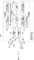
- Fig. 3A and Fig. 3B illustrate a simplified block diagram of an advanced wireless communication system 200, according to an embodiment of the present invention.
- the advanced wireless communication system 200 includes base stations 229 (an FDD advanced base station 210, representing a FDD access node such as the FDD macro cell access node 101 of Fig. 1, and a TDD advanced base station 230, representing a TDD access node such as the TDD small cell access node 103 of Fig. 1).
- the advanced wireless communication system 200 further includes a simplified block diagram of an advanced UE 250, representing UE capable of performing inter system FDD-TDD CA, such as the UE 104 or 105 of Fig. 1.
- the advanced FDD base station 210 comprises a processor 211, a memory 212 containing program instructions and databases, a FDD radio frequency (RF) module 213 having transmitter operating on DL carrier component and a receiver operating on UL carrier component, an antenna array 214 for transmitting cellular radio frequency signal (270.1 of radio frequency signal 270) to UEs in the cell and receiving radio frequency signal (270.2 of radio frequency signal 270) from UEs in the cell, and a TX module 215 for performing DL transport channels and physical channels coding and signal processing as well as control signal and reference signal processing.
- the advanced FDD base station 210 further comprises a RX module 216 for performing UL channels reception, signal processing, and channel decoding.
- the RX module 216 further comprises HARQ-ACK de-mapping module 225 for decoding and interpreting received HARQ-ACK symbols on PUCCH, as discussed in further detail below.
- the advanced TDD base station 230 comprises a processor 231, a memory 232 containing program instructions and databases, a TDD radio frequency (RF) module 233 having transmitter and receiver operating on the same carrier component, an antenna array 234 for transmitting and receiving cellular radio frequency signal (280.1, 280.2 and 280.3 of radio frequency signal 280) to UEs and from UEs in the cell, a TX module 235 for performing DL transport channels and physical channels coding and signal processing as well as control signal and reference signal processing, and an RX module 236 for performing UL channels reception, signal processing, and channel decoding.
- the RX module 236 further comprises HARQ-ACK de-mapping module 245 for decoding and interpreting received HARQ-ACK symbols on PUCCH or PUSCH, as discussed further below.
- the advanced UE 250 comprises a processor 251, a memory 252 containing program instructions and databases, a FDD radio frequency (RF) module 253 having transmitter operating on UL carrier component and a receiver operating on DL carrier component, antennas 254 for transmitting cellular radio frequency signal (270.2) to a servicing FDD base station and receiving radio frequency signal (270.1) from the servicing FDD base station, a TDD radio frequency (RF) module 255 having transmitter and receiver operating on the same carrier component, antennas 256 for transmitting and receiving cellular radio frequency signal (280) to and from the servicing TDD base station, and a RX module 257 for performing DL transport channels and physical channels reception, signal processing and decoding.
- RF radio frequency
- the RX module 257 further comprises a TX module 258 for performing UL channels encoding and transmissions, the TX module comprising a HARQ-ACK mapping and concatenation module 265 for encoding transmitted HARQ-ACK symbols, as discussed in further details below.
- a first aspect of the present invention relates to DL HARQ timing for an FDD Scell in an FDD-TDD CA system including a TDD Pcell.
- the FDD Scell follows DL HARQ-ACK timing of the TDD Pcell, and new HARQ timing is provided for additional DL subframes, which are not included in the TDD Pcell DL HARQ-timing, as discussed below.
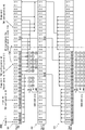
- Fig. 4A illustrates a timing diagram 300A, which is used to assist in explaining PDSCH HARQ timing of an FDD SCell according to PDSCH HARQ timing of a TDD PCell.
- Figs. 4A-4C show the PDSCH HARQ timing of the TDD PCell 301, UL timing of the FDD Scell 302 and DL timing of the FDD Scell 303.
- the TDD Pcell is configured with 3GPP LTE TDD configuration #5 in Frame#n.
- a HARQ-ACK for the TDD Pcell and DL subframe #9(304) in frame#(n-1), and DL subframe#0(305), #1(306), #3(307), #4(308), #5(309), #6(310),#7(311), and #8(312) in frame#(n) is fed back on UL subframe#2 (either 316 or 324) on frame#n+1, according to legacy 3GPP LTE.
- a HARQ-ACK for the FDD Scell and DL subframe #9(326) in frame#(n-1), DL subframe#0(327), #1(328), #2(329), #3(330), #4(331), #5(332), #6(333), #7(334), and #8(335) on frame#n is fed back on UL subframe #2 (either 316 or 324) on Frame#n+1.
- New HARQ-timing is designed for DL subframe#2(329), as discussed below, as no such corresponding frame is included in the TDD PCell.
- the HARQ process of legacy Rel.8-11 LTE TDD systems is disrupted when a TDD serving cell is reconfigured.
- the UE if the UE successfully detects the reconfiguration signalling in DL subframe#5 (319) in radio frame (n+1) sent on SIB-1, the UE will immediately apply the newly detected TDD configuration to the incoming radio frame.
- the timing in radio frame#n+2 follows the new TDD configuration, namely 3GPP LTE TDD configuration #2.
- ACK/NACK for DL subframe#4(318), #5(319), #6(320), #8(322) in radio frame #(n+1) will be fed back on UL subframe#2(323 or 325) on radio frame#n+2.
- ACK/NACK for DL transmission of the remaining DL/special subframes namely, DL subframe#9(313) on frame#n, and DL subframe#0(314), #1(315), #3(317) and #7(321) on frame#n+1, are dropped as they do not relate to the HARQ-ACK configuration defined in 3GPP LTE TDD configuration #2.
- the impact of HARQ disruption due to reconfiguration is not only on the TDD Pcell to which the reconfiguration relates, but also on the aggregated FDD Scell. Such impact is not negligible, particularly as there could be up to 4 aggregated FDD Scells, each of which will be be disrupted.
- TDD Pcell DL PDSCH HARQ timing in FDD Scells is that ambiguity in transmission direction of one or more subframes can occur. This is particularly the case for TDD-eIMTA systems.
- the UE may miss-detect a TDD reconfiguration signalling, and thus adopt a fall back method, such as following a legacy SIB-1 TDD configuration, or an implicit configuration. As such, correct identification of the transmission direction of all subframes may not occur and, as a result, the HARQ-ACK of an FDD Scell can be misaligned.
- a reference configuration for DL HARQ timing on an aggregated SCell is indicated through high layer signalling, e.g. RRC signalling.
- High layer signalling is signalling at a layer above a Physical Layer of the system, and preferably above a Data Link Layer of the system.
- a Network Layer of the system is a suitable high layer for providing DL HARQ timing on the aggregated SCell.
- 3GPP LTE TDD configuration #5 is configured by high layer (i.e. RRC) signalling as the reference configuration for DL HARQ timing. Furthermore, the HARQ-ACK for additional DL subframes is also fed back on the same UL subframe.
- RRC high layer
- the DL HARQ timing of the FDD Scell is not changed.
- the HARQ process on the TDD Pcell is disrupted, but the HARQ process for FDD Scell is not, since the reference timing of the FDD Scell is not changed. Accordingly, the impact of TDD reconfiguration of TDD Pcell can be limited to the TDD Pcell only.
- a second aspect of the present invention relates to DL HARQ timing for a TDD Scell with eIMTA operation in an inter-band CA system, when the Pcell is a TDD Pcell without eIMTA operation.
- DL HARQ-timing of the TDD Scell is determined based on a combination of TDD configurations of the Pcell and the Scell. For instance, if the Pcell is configured with TDD configuration#2 and the Scell, Scell-1, is configured with TDD configuration#1, then TDD configuration#2 is adopted by Scell-1 as the reference TDD configuration for DL HARQ-timing.
- the reference configuration for HARQ timing is configured through high layer signaling and the TDD configuration is configured using physical layer signalling, because fast TDD configuration is used in TDD eIMTA systems.
- the reference timing of DL HARQ for a TDD eIMTA Scell in an inter-band CA system is based on high layer (e.g. RRC) signalling.
- high layer e.g. RRC
- the eNB is fully aware of the TDD configuration pair of the Pcell and the Scell, a reference configuration can be configured on the high layer accordingly.
- the reliability of the reference signalling is independent of an accurate detection of a TDD configuration change in the TDD Pcell.
- a third aspect of the present invention relates to a method of concatenating PDSCH HARQ-ACK bits in an FDD-TDD CA system where the PCell is a TDD Pcell.
- the TDD Pcell is reconfigured to change from TDD configuration#5 to TDD configuration#2, either through SIB-1 signalling in a Rel.8-11 TDD system, or through physical layer signalling in a Rel.12 TDD eIMTA system.
- the UE may miss-detect several TDD SIB-1 configuration messages, and thus continue to use out-dated system information. This in turn results in a different TDD configurations being used at the eNB and at the UE.
- the UE may miss-detect physical layer signalling which is used to inform UE a fast TDD reconfiguration in the case of eIMTA. As such, the UE may not have the required information to correctly determine whether a subframe is used for DL or UL transmission.
- TDD ambiguity The adoption of different TDD configurations between the eNB and the UE is referred to herein as "TDD ambiguity".
- certain embodiments of the present invention comprise a method of concatenating HARQ-ACK from serving cells, as described below.
- HARQ-ACK bits for FDD serving cells are prioritized when concatenating HARQ-ACK bits in an FDD-TDD CA system.
- HARQ-ACK bits are concatenated for each of the serving cells, with the serving cell having lowest cell index mapped first, followed by the serving cell with next lowest cell index, which is repeated until all serving cells are mapped.
- the HARQ-ACK bits are concatenated depending only on service cell indexing, and in the same way regardless of whether a serving cell is a Pcell or an Scell.
- Fig. 4B As illustrated in Fig. 4B (300B), if the Rel.10/11 CA scheme is applied in an FDD-TDD CA system and the UE miss-detects the new TDD configuration signalling (i.e. 3GPP LTE TDD configuration #2), the UE will incorrectly apply 3GPP LTE TDD configuration #5 for frame#n+2 on the TDD Pcell.
- 3GPP LTE TDD configuration #2 the UE will incorrectly apply 3GPP LTE TDD configuration #5 for frame#n+2 on the TDD Pcell.
- the example described with reference to Fig. 4B assumes there is a PDSCH/PDCCH transmission on each DL/special subframe and HARQ-ACK is fed back on PUCCH.
- HARQ-ACK bits, HARQ-ACK(0) ⁇ HARQ-ACK(8) are generated for DLsubframe#9 (313) in frame #n, and DL subframe#0(314), #1(315), #3(317), #4(318), #5(319), #6(320), #7(321) and #8(322) in frame#n+1 on the TDD Pcell.
- HARQ-ACK bits HARQ-ACK(9) ⁇ HARQ-ACK(18) are generated for DL subframe#9(336) in frame #n, and DL subframe#0(337), #1(338), #2(339), #3(340), #4(341), #5(342), #6(343), #7(344) and #8(345) in frame#n+1 on the FDD Scell.
- HARQ-ACK bits, HARQ-ACK(0) ⁇ HARQ-ACK(3) are expected for DL subframe#4(318),#5(319),#6(320), and #8(322) in frame#n+1 on the TDD Pcell.
- 10 HARQ-ACK bits, HARQ-ACK(4) ⁇ HARQ-ACK(13) are expected for DL subframe#9(336) in frame #n, DL subframe#0(337), #1(338), #2(339), #3(340), #4(341), #5(342), #6(343), #7(344) and #8(345) in frame#n+1 on the FDD Scell.
- the HARQ-ACK bits for the FDD Scell are also misaligned because they are concatenated after the HARQ-ACK bits for the TDD Pcell.
- certain embodiments of the present invention provide concatenation of the HARQ-ACK bits such that bits associated with a low error probability are concatenated before bits associated with a high error probability.
- the FDD serving cell(s) are concatenated first, followed by the TDD serving cell(s) with less ambiguity issue(s) (e.g. Rel.8-11 TDD serving cell reconfigured with SIB-1 signalling), and then followed by TDD serving cell(s) with higher ambiguity issue(s) (e.g. Rel.12 TDD eIMTA system with physical layer reconfiguration signalling).
- HARQ-ACK(0) ⁇ HARQ-ACK(9) are generated for the FDD Scell on DL subframe#9 (336) in Frame#n, and DL subframe#0 (337), #1 (338), #2 (339), #3 (340), #4 (341), #5 (342), #6 (343), #7 (344), #8 (345) in Frame#n+1.
- HARQ-ACK bits 9 HARQ-ACK bits, HARQ-ACK(10) ⁇ HARQ-ACK(18), are generated for the TDD Pcell on DL subframe#9 (313) in Frame#n, and DL subframe#0 (314), #1 (315), #3 (317), #4 (318), #5 (319), #6 (320), #7 (321) and #8 (322) in Frame#n+1.
- HARQ-ACK bits are expected, with 10 HARQ-ACK bits being for the FDD Scell and 4 HARQ-ACK bits for the TDD Pcell.
- the eNB cannot correctly map the HARQ-ACK bits to DL transmission on the TDD Pcell, a correct mapping between HARQ-ACK bits and DL transmission on the FDD Scell is provided.
- HARQ-ACK bits for the FDD Scell are generated first, they are not influenced by the ambiguity problem of the TDD Pcell, and thus a correct mapping between HARQ-ACK bits and DL transmission on FDD Scell is provided.
- a fourth aspect of the present invention relates to a method of concatenating PDSCH HARQ-ACK bits in an inter-band CA system with different TDD configuration on different carrier components.
- the number of HARQ-ACK bits for serving cell is equal to if the transmission mode configured in the serving cell c supports one transport block or spatial HARQ-ACK bundling is applied, and otherwise. is the number of downlink subframes for which the UE needs to feedback HARQ-ACK bits for the c-th serving cell.
- M c is the number of elements in set K c associated with subframe n for serving cell c, wherein set K c contains values of such that subframe n-k corresponds to a DL subframe or a special subframe for serving cell c, and K is defined in Table 10.1.3.1-1 of 3GPP TS 36.213, where "UL/DL configuration" in Table 10.1.3.1-1 refers to the DL-reference UL/DL configuration, and is associated with subframe n.
- W(UL,DAI) If the value of W(UL,DAI) is available and DL-reference UL/DL configuration of each of the configured serving cells belongs to ⁇ 0, 1, 2, 3, 4, 6 ⁇ , . If the value of W(UL,DAI) is available and if DL-reference UL/DL configuration of at least one configured serving cell belongs to ⁇ 5 ⁇ , .
- the value of is a function of M c , which is the number of elements in set K c .
- the value of M c on the TDD Pcell 401 is 4, and thus 4 HARQ-ACK bits, HARQ-ACK(0) ⁇ HARQ-ACK(3), are generated by the UE for DL subframe#9(406 ), #0(407 ), #1(408 ), and #3(409).
- the eNB also expects 4 HARQ-ACK bits for the TDD Pcell 401, assuming no ambiguity problems exist on the TDD Pcell 401.
- Subframe#3 is treated as a DL subframe by the UE, the value of M c is 4 and 4 HARQ-ACK bits, HARQ-ACK(4) ⁇ HARQ-ACK(7), are generated by the UE.
- Subframe#3 (414) is treated as an UL subframe and thus only 3 HARQ-ACK bits, HARQ-ACK(4) ⁇ HARQ-ACK(6), are expected.
- one more HARQ-ACK bit, HARQ-ACK(7) is generated by the UE than is expected by the eNB.
- the value of M c is 3 because subframe #3 is considered as a UL subframe at the UE side and thus not included in set K c .
- 3 HARQ-ACK bits, HARQ-ACK(8) ⁇ HARQ-ACK(10), are thus generated by the UE.
- the eNB is expecting the same number of HARQ-ACK bits as were generated by the UE, but on HARQ-ACK(7) ⁇ HARQ-ACK(9) instead of HARQ-ACK(8) ⁇ HARQ-ACK(10).
- HARQ-ACK(7) ⁇ HARQ-ACK(9) are mapped to DL transmission of TDD-eIMTA Scell-2 403 on DL subframe#9(417) in Frame#n, and DL subframe#0(418) and #1(419) in Frame#n+1, respectively.
- the HARQ-ACK bits for TDD- eIMTA Scell-2 403 are misaligned, although no ambiguity problem exists specifically in regard to Scell-2.
- the legacy procedure specified for inter-band CA system is not robust enough for a TDD inter-band CA system, especially when the eNB and the UE may have different understanding in terms of the transmission direction of certain subframe(s).
- the number of HARQ-ACK bits is determined according to the number of DL/special subframes in the DL reference configuration associated with subframe n, i.e. the value M.
- HARQ-ACK(0) ⁇ HARQ-ACK(3) are generated for the TDD Pcell 401 by using configured DL reference timing of 3GPP LTE TDD configuration#2
- HARQ-ACK(4) ⁇ HARQ-ACK(7) are generated for TDD-eIMTA Scell-1 402 by using configured DL reference timing of 3GPP LTE TDD configuration#2
- HARQ-ACK(8) ⁇ HARQ-ACK(11) are generated for TDD-eIMTA Scell-2 403.
- the same number and sequence of HARQ-ACK bits are expected. As a result, even if there is an ambiguity problem between UE and eNB, the HARQ-ACK feedback can still be correctly mapped to related DL transmission on each serving cell.
- Non-transitory computer readable media include any type of tangible storage media. Examples of non-transitory computer readable media include magnetic storage media (such as floppy disks, magnetic tapes, hard disk drives, etc.), optical magnetic storage media (e.g.
- the software modules may be provided to a computer using any type of transitory computer readable media.
- transitory computer readable media include electric signals, optical signals, and electromagnetic waves.
- Transitory computer readable media can provide the software modules to a computer via a wired communication line (e.g. electric wires, and optical fibers) or a wireless communication line.
- ADVANCED WIRELESS COMMUNICATION SYSTEM 101 FDD MACRO CELL ACCESS NODE 102 FDD SMALL CELL ACCESS NODE 103 TDD SMALL CELL ACCESS NODE 104, 105, 106 USER EQUIPMENT (UE) 111 FIRST DEPLOYMENT SCENARIO 112 ANOTHER SCENARIO 121 LINE OF FLOW 200 ADVANCED WIRELESS COMMUNICATION SYSTEM 210 FDD ADVANCED BASE STATION 211 PROCESSOR 212 MEMORY 213 FDD RADIO FREQUENCY (RF) MODULE 214 ANTENNA ARRAY 215 TX MODULE 216 RX MODULE 225 HARQ-ACK DE-MAPPING MODULE 229 BASE STATION 230 TDD ADVANCED BASE STATION 231 PROCESSOR 232 MEMORY 233 TDD RADIO FREQUENCY (RF) MODULE 234 ANTENNA ARRAY
Abstract
A signalling method is disclosed for use in an advanced wireless communication network (100) that supports a TDD duplex mode and carrier aggregation of the TDD duplex mode and a second duplex mode, the method includes: configuring a user equipment (104) for data communication with the advanced wireless communication network (100) through a first access node (103) as a primary component carrier (PCell), on the TDD duplex mode; configuring the user equipment (104) for data communication with the advanced wireless communication network (100) through a second access node (101) as a secondary component carrier (SCell) on the second duplex mode; and configuring, by high layer signaling, the user equipment (104) to provide acknowledgement messages relating to data of the second access node (101) according to a reference configuration.
Description
The present invention relates to a signalling method.
The following abbreviations may be found herein:

3GPP Evolved UMTS Terrestrial Radio Access (E-UTRA) supports both FDD (full duplex) and TDD (half duplex) duplex modes. The behaviour of terminals simultaneously connected using different duplex modes has, however, not been specified. For network operators with both FDD and TDD spectrum, mechanisms that enable simultaneous use of both FDD and TDD spectrum resources, and thus allow both spectrum resources to be well (preferably fully) utilized, are desirable. As such, efficient TDD and FDD spectrum usage, and utilization of different technologies jointly, are expected to become more important for future LTE deployments in order to accommodate increased throughput and capacity needs.
The use of carrier aggregation (CA) offers a means for increasing peak data rates and throughput by aggregating multiple carrier components, as was discovered during 3GPP Release 10 LTE development, and enhanced during 3GPP Rel. 11 LTE CA enhancement work. It is expected that future LTE FDD-TDD CA deployment scenarios may allow either TDD or FDD cells to be used as a PCell and therefore, support for generic LTE FDD-TDD CA is desirable.
Several problems exist, however, in supporting generic LTE FDD-TDD CA. For example, no efficient Hybrid Automatic Repeat reQuest (HARQ) timing for FDD-TDD CA operation exists.
When a Pcell is configured with TDD and an Scell is configured with FDD, PDSCH HARQ timing of the FDD Scell often follows a PDSCH HARQ timing of the TDD Pcell. However, in such case the eNB and the UE can have different understandings in terms of the adopted TDD configuration, and more importantly, the impact of TDD configuration ambiguity is not restricted to the TDD serving cell, but also impacts the FDD serving cell.
In Rel.8-11 LTE systems of the related art, a change of system information (other than for ETWS and CMAS) occurs only at specific radio frames and thus the concept of a modification period is defined. System information may be transmitted a number of times, with the same content, within a modification period. Boundaries of the modification period are defined by SFN values for which SFN mod m= 0, where m is the number of radio frames comprising the modification period. The modification period is configured by system information, but has a minimum value of 640 ms.
For TDD serving cells without eIMTA operation, information about an allocation of subframes to uplink/downlink is conveyed by SIB1 (System Information Block Type1) signaling, which uses a fixed schedule with a periodicity of 80 ms. The first transmission of SIB1 is scheduled in subframe # 5 of radio frames for which the SFN mod 8 = 0, and repetitions are scheduled in subframe # 5 of all other radio frames for which SFN mod 2 = 0. Since system information such as TDD configuration is changed less frequently, decoding of information every 80ms is generally not necessary. As such decoding of information is also energy consuming, such information is often only decoded when the UE is notified that a change will happen.
Fig. 1 illustrates a change of system information 10, including first system information 12a, second system information 12b, and third system information 12c, according to the related art. When the network changes (some of the) the first, second or third system information 12a, 12b, 12c, it first notifies the UEs about this change, which may be done throughout a first modification period 14a. In a second modification period 14b that is subsequent to the first modification period 14a, the network transmits the updated system information.
Upon receiving a change notification, the UE acquires the new system information immediately from the start of the next modification period. The UE applies the previously acquired system information until the UE acquires the new system information.
When the UE is updated with the new TDD configuration, the HARQ-timing is also updated. As such, there could be no HARQ-ACK feedback for certain UL/DL transmission on the first modification period 14a. The impact of such HARQ process disruption caused by SIB-1 reconfiguration may not be severe in non-CA cases since the reconfiguration interval is at least 640ms, and more importantly, the impact is limited only to one TDD serving cell.
In FDD-TDD CA system with a TDD Pcell and at least one FDD Scell, if the DL PDSCH HARQ-timing of the FDD Scell follows a PDSCH HARQ timing of the TDD Pcell, as discussed above, the HARQ-process on the FDD Scell will also be disrupted when the TDD Pcell is reconfigured. Such impact can become significant if there are several FDD Scells.
In Rel.10/11 TDD systems, the UE may not be able to decode the first SIB-1 on the TDD Pcell because of the poor radio channel conditions. As a result, there could be more than one radio frame in which the eNB and the UE apply different TDD configurations on one serving cell, which can result in ambiguity in PDSCH HARQ-ACK timing and feedback mode.
In an FDD-TDD CA system, errors caused by TDD configuration ambiguity may also impact HARQ-ACK bits for other serving cells, even if the other serving cells do not have such a configuration ambiguity problem. Furthermore when the TDD SCell is configured with eIMTA, a reconfiguration period could be as short as 10ms. In such case, ambiguity between eNB and UE in terms of adopted TDD configuration can happen frequently.
As such, when a UE fails to detect a reconfiguration signalling, there could be more than one radio frames where the UE and the eNB may have different understandings in terms of the mapping between PDSCH/PDCCH/EPDCCH and PDSCH HARQ-ACK. This can in turn cause unnecessary retransmission for some PDSCH/PDCCH/EPDCCH data, or a lack of scheduling retransmission for certain PDSCH/PDCCH/EPDCCH data which is required by the UE.
It will be clearly understood that, if a related art publication is referred to herein, this reference does not constitute an admission that the publication forms part of the common general knowledge in the art in Australia or in any other country.
The present invention is directed to control signalling in advanced wireless communication networks, which may at least partially overcome at least one of the abovementioned disadvantages or provide the consumer with a useful or commercial choice.
With the foregoing in view, the present invention in one form, resides broadly in a signalling method for use in an advanced wireless communication network that supports a TDD duplex mode and carrier aggregation of the TDD duplex mode and a second duplex mode, the method including:
configuring a user equipment for data communication with the advanced wireless communication network through a first access node as a primary component carrier (PCell), on the TDD duplex mode;
configuring the user equipment for data communication with the advanced wireless communication network through a second access node as a secondary component carrier (SCell) on the second duplex mode; and
configuring, by high layer signaling, the user equipment to provide acknowledgement messages relating to data of the second access node according to a reference configuration.
According to certain embodiments, the high layer signaling comprises network layer signaling. In particular, the high layer signaling can comprise RRC signaling.
According to some embodiments, the acknowledgement messages comprise HARQ-ACK messages.
According to certain embodiments, the second duplex mode comprises an FDD duplex mode.
According to certain embodiments, the signaling method further comprises: subsequent to configuring the user equipment to provide acknowledgement messages relating to data of the second access node according to the reference configuration, configuring the user equipment to provide acknowledgement messages relating to data of the first access node according to an updated configuration.
According to other embodiments, the Scell comprises a TDD Scell with eIMTA operation. Furthermore, the Pcell can comprise a TDD Pcell without eIMTA operation.
In another form, the present invention resides broadly in a signalling method for use in an advanced wireless communication network that supports a first duplex mode, a second duplex mode and carrier aggregation of the first duplex mode and the second duplex mode, the method including:
configuring a user equipment for data communication with the advanced wireless communication network through a first access node as a primary component carrier (PCell), on the first duplex mode;
configuring the user equipment for data communication with the advanced wireless communication network through a second access node as a secondary component carrier (SCell) on the second duplex mode; and
configuring the user equipment to provide acknowledgement messages relating to data of the first access node and the second access node by concatenating the acknowledgement messages according to a duplex mode associated with each of the acknowledgement messages.
According to certain embodiments, the acknowledgement messages are concatenated according to an error probability associated with subframes in the corresponding access node, wherein messages associated with an access node having low ambiguity probability are concatenated before messages associated with an access node with high error probability.
According to some embodiments, the error probability comprises a probability of transmission direction ambiguity of subframes of the corresponding access node.
According to certain embodiments, acknowledgement messages associated with an FDD duplex mode are concatenated before acknowledgement messages associated with a TDD duplex mode. Similarly, according to other embodiments, acknowledgement messages associated with a TDD duplex mode without eIMTA operation are concatenated before acknowledgement messages associated with a TDD duplex mode with eIMTA operation.
In particular, according to certain embodiments, acknowledgement messages associated with an FDD serving cell are concatenated before acknowledgement messages associated with a TDD duplex mode without eIMTA, which are concatenated before acknowledgement messages associated with a TDD duplex mode with eIMTA operation.
In yet another form, the present invention resides broadly in a signalling method for use in an advanced wireless communication network that supports a first duplex mode, a second duplex mode, and carrier aggregation of the first duplex mode and a second duplex mode, the method including:
configuring a user equipment for data communication with the advanced wireless communication network through a first access node as a primary component carrier (PCell), on the first duplex mode;
configuring the user equipment for data communication with the advanced wireless communication network through a second access node as a secondary component carrier (SCell) on the second duplex mode; and
configuring the user equipment to provide acknowledgement messages relating to data of the first access node and the second access node by concatenating a first acknowledgement message of the first access node with a second acknowledgement message of the second access node, wherein a length of the first acknowledgement message is defined according to a reference configuration of the first access node, and a length of the second acknowledgement message is defined according to a reference configuration of the second access node.
According to certain embodiments, the length of the second acknowledgement message is defined according to a number of DL and special subframes of the reference configuration of the second access node. According to other embodiments, the length of the first acknowledgement message is defined according to a number of DL and special subframes of the reference configuration of the first access node.
According to certain embodiments, the method further comprises configuring the user equipment for data communication with the advanced wireless communication network through a second access node according to a configuration of the second access node that is different to the reference configuration of the first access node.
Any of the features described herein can be combined in any combination with any one or more of the other features described herein within the scope of the invention.
The reference to any related art in this specification is not, and should not be taken as an acknowledgement or any form of suggestion that the related art forms part of the common general knowledge.
According to the present invention, it is possible to provide a signalling method which can decrease impact of configuration ambiguity.
Preferred features, embodiments and variations of the invention may be discerned from the following Detailed Description which provides sufficient information for those skilled in the art to perform the invention. The Detailed Description is not to be regarded as limiting the scope of the preceding Summary of the Invention in any way. The Detailed Description will make reference to a number of drawings as follows:
Fig. 1 illustrates a change of system information, according to the related art.
Fig. 2 illustrates an advanced wireless communication system, according to an embodiment of the present invention.
Fig. 3A illustrates a simplified block diagram of an advanced wireless communication system, according to an embodiment of the present invention.
Fig. 3B illustrates a simplified block diagram of an advanced wireless communication system, according to an embodiment of the present invention.
Fig. 4A illustrates a timing diagram, which is used to assist in explaining PDSCH HARQ timing of an FDD SCell according to PDSCH HARQ timing of a TDD PCell, according to an embodiment of the present invention.
Fig. 4B illustrates a timing diagram, which is used to assist in explaining PDSCH HARQ timing of an FDD according to an RRC configured reference configuration, according to an embodiment of the present invention.
Fig. 4C illustrates a timing diagram, which is used to assist in explaining HARQ-ACK bit concatenation, according to an embodiment of the present invention.
Fig. 5A illustrates a timing diagram, which is used to assist explaining PDSCH HARQ timing with some SCells being TDD-eIMTA, according to an embodiment of the present invention.
Fig. 5B illustrates a timing diagram, which is used to assist explaining HARQ-ACK bit concatenation, according to an embodiment of the present invention.
Fig. 2 illustrates an advanced wireless communication system 100, according to an embodiment of the present invention. The advanced wireless communication system 100 enables efficient FDD and TDD carrier aggregation.
The advanced wireless communication system 100 comprises a plurality of FDD macro cell access nodes 101, representing macro base stations that can be configured to transmit and receive FDD signals on separated DL and UL carrier frequencies, and a plurality of FDD small cell access nodes 102, representing pico base stations that can be configured to transmit and receive FDD signals on separate DL and UL carrier frequencies. The advanced wireless communication system 100 further comprises a plurality of TDD small cell access nodes 103 representing pico base stations that can be configured to transmit and receive DL and UL TDD signals on a single carrier frequency, and a plurality of advanced user equipments (UEs) 104, 105 and 106 that are capable of performing FDD signal transmission and reception, TDD signal transmission and reception, and FDD-TDD signal transmission and reception in the form of FDD-TDD Carrier Aggregation.
The FDD macro cell access nodes 101 serve macro-cells over a first paired carrier frequency F1, each macro-cell providing large coverage. The FDD small cell access nodes 102 serve small-cells over a second paired carrier frequency F2 and the TDD small cell access nodes 103 serve small-cells over a third unpaired carrier frequency F3.
The first carrier frequency F1 and the second carrier frequency F2 can comprise a same or different carrier frequency. Furthermore, a UL carrier frequency component of the first carrier frequency F1, and the third carrier frequency F3 can comprise a same or different carrier frequency.
The FDD macro cell access node 101 interconnects with the FDD small cell access nodes 102 and the TDD small cell access nodes 103 by a backhaul (not shown).
According to certain embodiments of the present invention, the advanced wireless communication system 100 enables FDD-TDD carrier aggregation where a TDD carrier is the PCell and FDD carrier(s) are the SCell, as illustrated by a first deployment scenario 111, or where both FDD and TDD carriers are SCells. (As a reference, Fig. 2 shows another scenario 112, in which the FDD macro cell access node 101 and UE 105 communicate with each other in normal way.)
According the first deployment scenario 111, the UE 104 initially detects and camps on a TDD small cell access node 103. (The UE 104 can move along a line of flow 121.) The UE 104 establishes an RRC connection with the advanced mobile system 100 through the TDD small cell access node 103 on TDD carriers. Simultaneous transmission and/or reception of data from an FDD macro cell access node 101 with overlapping coverage, other neighbouring TDD small cell access nodes 103 and/or FDD small cell access nodes 102 may also be possible. Via dedicated RRC signalling through TDD small cell access node 103, the UE 104 is configured to perform FDD macro cell measurement and to add a second FDD carrier component serviced by the FDD macro cell access node 101 as aggregated carrier for additional data reception and transmission. The second FDD carrier component is added in addition to a primary TDD carrier component that is serviced by the TDD small cell access node 103.
The primary carrier component (or PCell) serviced by the TDD small cell access node 103 is LTE TDD where the secondary carrier component (SCell) serviced by the FDD macro cell access node 101 is LTE FDD. Furthermore, there may be more than one SCell in the first deployment scenario 111.
Fig. 3A and Fig. 3B illustrate a simplified block diagram of an advanced wireless communication system 200, according to an embodiment of the present invention. The advanced wireless communication system 200 includes base stations 229 (an FDD advanced base station 210, representing a FDD access node such as the FDD macro cell access node 101 of Fig. 1, and a TDD advanced base station 230, representing a TDD access node such as the TDD small cell access node 103 of Fig. 1). The advanced wireless communication system 200 further includes a simplified block diagram of an advanced UE 250, representing UE capable of performing inter system FDD-TDD CA, such as the UE 104 or 105 of Fig. 1.
The advanced FDD base station 210 comprises a processor 211, a memory 212 containing program instructions and databases, a FDD radio frequency (RF) module 213 having transmitter operating on DL carrier component and a receiver operating on UL carrier component, an antenna array 214 for transmitting cellular radio frequency signal (270.1 of radio frequency signal 270) to UEs in the cell and receiving radio frequency signal (270.2 of radio frequency signal 270) from UEs in the cell, and a TX module 215 for performing DL transport channels and physical channels coding and signal processing as well as control signal and reference signal processing. The advanced FDD base station 210 further comprises a RX module 216 for performing UL channels reception, signal processing, and channel decoding. The RX module 216 further comprises HARQ-ACK de-mapping module 225 for decoding and interpreting received HARQ-ACK symbols on PUCCH, as discussed in further detail below.
The advanced TDD base station 230 comprises a processor 231, a memory 232 containing program instructions and databases, a TDD radio frequency (RF) module 233 having transmitter and receiver operating on the same carrier component, an antenna array 234 for transmitting and receiving cellular radio frequency signal (280.1, 280.2 and 280.3 of radio frequency signal 280) to UEs and from UEs in the cell, a TX module 235 for performing DL transport channels and physical channels coding and signal processing as well as control signal and reference signal processing, and an RX module 236 for performing UL channels reception, signal processing, and channel decoding. The RX module 236 further comprises HARQ-ACK de-mapping module 245 for decoding and interpreting received HARQ-ACK symbols on PUCCH or PUSCH, as discussed further below.
The advanced UE 250 comprises a processor 251, a memory 252 containing program instructions and databases, a FDD radio frequency (RF) module 253 having transmitter operating on UL carrier component and a receiver operating on DL carrier component, antennas 254 for transmitting cellular radio frequency signal (270.2) to a servicing FDD base station and receiving radio frequency signal (270.1) from the servicing FDD base station, a TDD radio frequency (RF) module 255 having transmitter and receiver operating on the same carrier component, antennas 256 for transmitting and receiving cellular radio frequency signal (280) to and from the servicing TDD base station, and a RX module 257 for performing DL transport channels and physical channels reception, signal processing and decoding. The RX module 257 further comprises a TX module 258 for performing UL channels encoding and transmissions, the TX module comprising a HARQ-ACK mapping and concatenation module 265 for encoding transmitted HARQ-ACK symbols, as discussed in further details below.
A first aspect of the present invention relates to DL HARQ timing for an FDD Scell in an FDD-TDD CA system including a TDD Pcell. In such case, the FDD Scell follows DL HARQ-ACK timing of the TDD Pcell, and new HARQ timing is provided for additional DL subframes, which are not included in the TDD Pcell DL HARQ-timing, as discussed below.
Fig. 4A illustrates a timing diagram 300A, which is used to assist in explaining PDSCH HARQ timing of an FDD SCell according to PDSCH HARQ timing of a TDD PCell. Figs. 4A-4C show the PDSCH HARQ timing of the TDD PCell 301, UL timing of the FDD Scell 302 and DL timing of the FDD Scell 303.
The TDD Pcell is configured with 3GPP LTE TDD configuration # 5 in Frame#n. As such, a HARQ-ACK for the TDD Pcell and DL subframe #9(304) in frame#(n-1), and DL subframe#0(305), #1(306), #3(307), #4(308), #5(309), #6(310),#7(311), and #8(312) in frame#(n) is fed back on UL subframe#2 (either 316 or 324) on frame#n+1, according to legacy 3GPP LTE. As the FDD Scell follows the HARQ timing of the TDD Pcell, a HARQ-ACK for the FDD Scell and DL subframe #9(326) in frame#(n-1), DL subframe#0(327), #1(328), #2(329), #3(330), #4(331), #5(332), #6(333), #7(334), and #8(335) on frame#n is fed back on UL subframe #2 (either 316 or 324) on Frame#n+1. New HARQ-timing is designed for DL subframe#2(329), as discussed below, as no such corresponding frame is included in the TDD PCell.
As discussed above, the HARQ process of legacy Rel.8-11 LTE TDD systems is disrupted when a TDD serving cell is reconfigured. As illustrated with reference to timing diagram 300A of Fig. 4A, if the UE successfully detects the reconfiguration signalling in DL subframe#5 (319) in radio frame (n+1) sent on SIB-1, the UE will immediately apply the newly detected TDD configuration to the incoming radio frame. In other words, the timing in radio frame#n+2 follows the new TDD configuration, namely 3GPP LTE TDD configuration # 2. As a result, only ACK/NACK for DL subframe#4(318), #5(319), #6(320), #8(322) in radio frame #(n+1) will be fed back on UL subframe#2(323 or 325) on radio frame#n+2. As such, ACK/NACK for DL transmission of the remaining DL/special subframes, namely, DL subframe#9(313) on frame#n, and DL subframe#0(314), #1(315), #3(317) and #7(321) on frame#n+1, are dropped as they do not relate to the HARQ-ACK configuration defined in 3GPP LTE TDD configuration # 2.
In FDD-TDD CA systems with a TDD Pcell and at least one FDD Scell, if the DL PDSCH HARQ-timing of the FDD Scell follows PDSCH HARQ timing of the TDD Pcell, as discussed above, the HARQ process on the FDD Scell will also be disrupted when the TDD Pcell is reconfigured with a new TDD configuration. With reference to the timing diagram 300A of Fig. 4A, no HARQ-ACK will be fed back for DL subframe #9(336) in frame#n, DL subframe#0(337), #1(338), #2(339), or #3(340) in frame#n+1 on the FDD Scell, due to the change in configuration mentioned above.
Thus, the impact of HARQ disruption due to reconfiguration is not only on the TDD Pcell to which the reconfiguration relates, but also on the aggregated FDD Scell. Such impact is not negligible, particularly as there could be up to 4 aggregated FDD Scells, each of which will be be disrupted.
A further problem with following TDD Pcell DL PDSCH HARQ timing in FDD Scells is that ambiguity in transmission direction of one or more subframes can occur. This is particularly the case for TDD-eIMTA systems. As an illustrative example, the UE may miss-detect a TDD reconfiguration signalling, and thus adopt a fall back method, such as following a legacy SIB-1 TDD configuration, or an implicit configuration. As such, correct identification of the transmission direction of all subframes may not occur and, as a result, the HARQ-ACK of an FDD Scell can be misaligned.
According to certain embodiments of the present invention, a reference configuration for DL HARQ timing on an aggregated SCell is indicated through high layer signalling, e.g. RRC signalling. High layer signalling is signalling at a layer above a Physical Layer of the system, and preferably above a Data Link Layer of the system. In particular, a Network Layer of the system is a suitable high layer for providing DL HARQ timing on the aggregated SCell.
As illustrated with reference to the timing diagram 300B of Fig. 4B, 3GPP LTE TDD configuration # 5 is configured by high layer (i.e. RRC) signalling as the reference configuration for DL HARQ timing. Furthermore, the HARQ-ACK for additional DL subframes is also fed back on the same UL subframe.
When the TDD configuration of the TDD Pcell is reconfigured from 3GPP LTE TDD configuration # 5 to 3GPP LTE TDD configuration # 2 on, for example the Physical Layer, the DL HARQ timing of the FDD Scell is not changed. As such, the HARQ process on the TDD Pcell is disrupted, but the HARQ process for FDD Scell is not, since the reference timing of the FDD Scell is not changed. Accordingly, the impact of TDD reconfiguration of TDD Pcell can be limited to the TDD Pcell only.
A second aspect of the present invention relates to DL HARQ timing for a TDD Scell with eIMTA operation in an inter-band CA system, when the Pcell is a TDD Pcell without eIMTA operation.
In a legacy Rel.11 inter-band CA system with different TDD configurations on different serving cells, DL HARQ-timing of the TDD Scell is determined based on a combination of TDD configurations of the Pcell and the Scell. For instance, if the Pcell is configured with TDD configuration# 2 and the Scell, Scell-1, is configured with TDD configuration# 1, then TDD configuration# 2 is adopted by Scell-1 as the reference TDD configuration for DL HARQ-timing.
In non-CA eIMTA systems, the reference configuration for HARQ timing is configured through high layer signaling and the TDD configuration is configured using physical layer signalling, because fast TDD configuration is used in TDD eIMTA systems.
As discussed above, several problems can occur when configuration signalling is not correctly received, in particular when such problems propagate between cells.
According to certain embodiments of the present invention, the reference timing of DL HARQ for a TDD eIMTA Scell in an inter-band CA system is based on high layer (e.g. RRC) signalling. As the eNB is fully aware of the TDD configuration pair of the Pcell and the Scell, a reference configuration can be configured on the high layer accordingly. As such, the reliability of the reference signalling is independent of an accurate detection of a TDD configuration change in the TDD Pcell.
A third aspect of the present invention relates to a method of concatenating PDSCH HARQ-ACK bits in an FDD-TDD CA system where the PCell is a TDD Pcell.
As illustrated in timing diagram 300B of Fig. 4B, the TDD Pcell is reconfigured to change from TDD configuration# 5 to TDD configuration# 2, either through SIB-1 signalling in a Rel.8-11 TDD system, or through physical layer signalling in a Rel.12 TDD eIMTA system.
It is, however, possible for the UE to miss-detect several TDD SIB-1 configuration messages, and thus continue to use out-dated system information. This in turn results in a different TDD configurations being used at the eNB and at the UE. Similarly, the UE may miss-detect physical layer signalling which is used to inform UE a fast TDD reconfiguration in the case of eIMTA. As such, the UE may not have the required information to correctly determine whether a subframe is used for DL or UL transmission. The adoption of different TDD configurations between the eNB and the UE is referred to herein as "TDD ambiguity".
In order to alleviate this TDD ambiguity, and to avoid propagating the impact of any ambiguity to other serving cells, certain embodiments of the present invention comprise a method of concatenating HARQ-ACK from serving cells, as described below. In such case, HARQ-ACK bits for FDD serving cells are prioritized when concatenating HARQ-ACK bits in an FDD-TDD CA system.
In legacy Rel.10/11 CA systems, HARQ-ACK bits are concatenated for each of the serving cells, with the serving cell having lowest cell index mapped first, followed by the serving cell with next lowest cell index, which is repeated until all serving cells are mapped. As such, the HARQ-ACK bits are concatenated depending only on service cell indexing, and in the same way regardless of whether a serving cell is a Pcell or an Scell.
As illustrated in Fig. 4B (300B), if the Rel.10/11 CA scheme is applied in an FDD-TDD CA system and the UE miss-detects the new TDD configuration signalling (i.e. 3GPP LTE TDD configuration #2), the UE will incorrectly apply 3GPP LTE TDD configuration # 5 for frame#n+2 on the TDD Pcell. For simplicity, the example described with reference to Fig. 4B assumes there is a PDSCH/PDCCH transmission on each DL/special subframe and HARQ-ACK is fed back on PUCCH.
At the UE side, HARQ-ACK bits, HARQ-ACK(0)~HARQ-ACK(8) are generated for DLsubframe#9 (313) in frame #n, and DL subframe#0(314), #1(315), #3(317), #4(318), #5(319), #6(320), #7(321) and #8(322) in frame#n+1 on the TDD Pcell. Furthermore, HARQ-ACK bits HARQ-ACK(9)~HARQ-ACK(18) are generated for DL subframe#9(336) in frame #n, and DL subframe#0(337), #1(338), #2(339), #3(340), #4(341), #5(342), #6(343), #7(344) and #8(345) in frame#n+1 on the FDD Scell.
At the eNB, 4 HARQ-ACK bits, HARQ-ACK(0)~HARQ-ACK(3), are expected for DL subframe#4(318),#5(319),#6(320), and #8(322) in frame#n+1 on the TDD Pcell. Furthermore, 10 HARQ-ACK bits, HARQ-ACK(4)~HARQ-ACK(13), are expected for DL subframe#9(336) in frame #n, DL subframe#0(337), #1(338), #2(339), #3(340), #4(341), #5(342), #6(343), #7(344) and #8(345) in frame#n+1 on the FDD Scell.
From the above example, it can be seen that not only is the TDD Pcell is impacted by the TDD ambiguity; the HARQ-ACK bits for the FDD Scell are also misaligned because they are concatenated after the HARQ-ACK bits for the TDD Pcell.
In order to alleviate the impact of this TDD ambiguity in FDD-TDD CA systems, and particularly on FDD Scells, certain embodiments of the present invention provide concatenation of the HARQ-ACK bits such that bits associated with a low error probability are concatenated before bits associated with a high error probability. In particular, the FDD serving cell(s) are concatenated first, followed by the TDD serving cell(s) with less ambiguity issue(s) (e.g. Rel.8-11 TDD serving cell reconfigured with SIB-1 signalling), and then followed by TDD serving cell(s) with higher ambiguity issue(s) (e.g. Rel.12 TDD eIMTA system with physical layer reconfiguration signalling).
As illustrated with reference to Fig. 4C (300C), at the UE 10 HARQ-ACK bits, HARQ-ACK(0)~HARQ-ACK(9), are generated for the FDD Scell on DL subframe#9 (336) in Frame#n, and DL subframe#0 (337), #1 (338), #2 (339), #3 (340), #4 (341), #5 (342), #6 (343), #7 (344), #8 (345) in Frame#n+1. Furthermore, 9 HARQ-ACK bits, HARQ-ACK(10)~HARQ-ACK(18), are generated for the TDD Pcell on DL subframe#9 (313) in Frame#n, and DL subframe#0 (314), #1 (315), #3 (317), #4 (318), #5 (319), #6 (320), #7 (321) and #8 (322) in Frame#n+1.
At the eNB side, 14 HARQ-ACK bits are expected, with 10 HARQ-ACK bits being for the FDD Scell and 4 HARQ-ACK bits for the TDD Pcell. Although the eNB cannot correctly map the HARQ-ACK bits to DL transmission on the TDD Pcell, a correct mapping between HARQ-ACK bits and DL transmission on the FDD Scell is provided.
As such, the above discussed ambiguity problem can be confined to the TDD Pcell. Since HARQ-ACK bits for the FDD Scell are generated first, they are not influenced by the ambiguity problem of the TDD Pcell, and thus a correct mapping between HARQ-ACK bits and DL transmission on FDD Scell is provided.
A fourth aspect of the present invention relates to a method of concatenating PDSCH HARQ-ACK bits in an inter-band CA system with different TDD configuration on different carrier components.
In legacy Rel.11 inter-band CA systems with different TDD configurations on different carrier components, i.e. inter-band CA systems, when PUCCH format 3 is configured for transmission of HARQ-ACK the procedure of HARQ-ACK generation is specified as follows:
The number of HARQ-ACK bits for serving cell

is equal to

if the transmission mode configured in the serving cell c supports one transport block or spatial HARQ-ACK bundling is applied, and

otherwise.

is the number of downlink subframes for which the UE needs to feedback HARQ-ACK bits for the c-th serving cell.
is equal to
if the transmission mode configured in the serving cell c supports one transport block or spatial HARQ-ACK bundling is applied, and
otherwise.
is the number of downlink subframes for which the UE needs to feedback HARQ-ACK bits for the c-th serving cell.

if the value of W(UL,DAI) is not available. Mc is the number of elements in set Kc associated with subframe n for serving cell c, wherein set Kc contains values of
such that subframe n-k corresponds to a DL subframe or a special subframe for serving cell c, and K is defined in Table 10.1.3.1-1 of 3GPP TS 36.213, where "UL/DL configuration" in Table 10.1.3.1-1 refers to the DL-reference UL/DL configuration, and is associated with subframe n.
If the value of W(UL,DAI) is available and DL-reference UL/DL configuration of each of the configured serving cells belongs to {0, 1, 2, 3, 4, 6},
 .
.
If the value of W(UL,DAI) is available and if DL-reference UL/DL configuration of at least one configured serving cell belongs to {5},
 .
.
If the value of W(UL,DAI) is available and if DL-reference UL/DL configuration of at least one configured serving cell belongs to {5},
As such, the value of

is a function of Mc, which is the number of elements in set Kc.
is a function of Mc, which is the number of elements in set Kc.
With reference to Fig. 5A, the value of Mc on the TDD Pcell 401 is 4, and thus 4 HARQ-ACK bits, HARQ-ACK(0)~HARQ-ACK(3), are generated by the UE for DL subframe#9(406 ), #0(407 ), #1(408 ), and #3(409). The eNB also expects 4 HARQ-ACK bits for the TDD Pcell 401, assuming no ambiguity problems exist on the TDD Pcell 401.
On TDD-eIMTA Scell-1 402, the UE and eNB have different understanding in terms of the transmission direction of subframe#3 (414) due to, for example, a mis-detection of fast signalling of the TDD configuration. As a result, Subframe# 3 is treated as a DL subframe by the UE, the value of Mc is 4 and 4 HARQ-ACK bits, HARQ-ACK(4)~HARQ-ACK(7), are generated by the UE. However, at the eNB, Subframe#3 (414) is treated as an UL subframe and thus only 3 HARQ-ACK bits, HARQ-ACK(4)~HARQ-ACK(6), are expected. In another words, one more HARQ-ACK bit, HARQ-ACK(7), is generated by the UE than is expected by the eNB.
For TDD-eIMTA Scell-2 403, the value of Mc is 3 because subframe # 3 is considered as a UL subframe at the UE side and thus not included in set Kc. 3 HARQ-ACK bits, HARQ-ACK(8)~HARQ-ACK(10), are thus generated by the UE. Assuming no ambiguity problem exists in regard to TDD-eIMTA Scell-2 403, the eNB is expecting the same number of HARQ-ACK bits as were generated by the UE, but on HARQ-ACK(7)~HARQ-ACK(9) instead of HARQ-ACK(8)~HARQ-ACK(10). To be specific, HARQ-ACK(7)~HARQ-ACK(9) are mapped to DL transmission of TDD-eIMTA Scell-2 403 on DL subframe#9(417) in Frame#n, and DL subframe#0(418) and #1(419) in Frame#n+1, respectively. Obviously, the HARQ-ACK bits for TDD- eIMTA Scell-2 403 are misaligned, although no ambiguity problem exists specifically in regard to Scell-2.
As such, the legacy procedure specified for inter-band CA system is not robust enough for a TDD inter-band CA system, especially when the eNB and the UE may have different understanding in terms of the transmission direction of certain subframe(s).
According to certain embodiments of the present invention, the number of HARQ-ACK bits is determined according to the number of DL/special subframes in the DL reference configuration associated with subframe n, i.e. the value M.
As illustrated in Fig. 5B (400B), at the UE side, HARQ-ACK(0)~HARQ-ACK(3) are generated for the TDD Pcell 401 by using configured DL reference timing of 3GPP LTE TDD configuration# 2, HARQ-ACK(4)~HARQ-ACK(7) are generated for TDD-eIMTA Scell-1 402 by using configured DL reference timing of 3GPP LTE TDD configuration# 2, and HARQ-ACK(8)~HARQ-ACK(11) are generated for TDD-eIMTA Scell-2 403. At the eNB side, the same number and sequence of HARQ-ACK bits are expected. As a result, even if there is an ambiguity problem between UE and eNB, the HARQ-ACK feedback can still be correctly mapped to related DL transmission on each serving cell.
In the present specification and claims (if any), the word 'comprising' and its derivatives including 'comprises' and 'comprise' include each of the stated integers but does not exclude the inclusion of one or more further integers.
Reference throughout this specification to 'one embodiment' or 'an embodiment' means that a particular feature, structure, or characteristic described in connection with the embodiment is included in at least one embodiment of the present invention. Thus, the appearance of the phrases 'in one embodiment' or 'in an embodiment' in various places throughout this specification are not necessarily all referring to the same embodiment. Furthermore, the particular features, structures, or characteristics may be combined in any suitable manner in one or more combinations.
In compliance with the statute, the invention has been described in language more or less specific to structural or methodical features. It is to be understood that the invention is not limited to specific features shown or described since the means herein described comprises preferred forms of putting the invention into effect. The invention is, therefore, claimed in any of its forms or modifications within the proper scope of the appended claims (if any) appropriately interpreted by those skilled in the art.
The above-mentioned processing may be executed by a computer. Also, it is possible to provide a computer program which causes a programmable computer device to execute the above-mentioned processing. The program can be stored and provided to a computer using any type of non-transitory computer readable media. Non-transitory computer readable media include any type of tangible storage media. Examples of non-transitory computer readable media include magnetic storage media (such as floppy disks, magnetic tapes, hard disk drives, etc.), optical magnetic storage media (e.g. magneto-optical disks), CD-ROM, CD-R, CD-R/W, and semiconductor memories (such as mask ROM, PROM (Programmable ROM), EPROM (Erasable PROM), flash ROM, RAM (Random Access Memory), etc.). The software modules may be provided to a computer using any type of transitory computer readable media. Examples of transitory computer readable media include electric signals, optical signals, and electromagnetic waves. Transitory computer readable media can provide the software modules to a computer via a wired communication line (e.g. electric wires, and optical fibers) or a wireless communication line.
This application is based upon and claims the benefit of priority from Australian provisional patent application No.2014900047, filed on January 8, 2014, the disclosure of which is incorporated herein in its entirely by reference.
100 ADVANCED WIRELESS COMMUNICATION SYSTEM
101 FDD MACRO CELL ACCESS NODE
102 FDD SMALL CELL ACCESS NODE
103 TDD SMALL CELL ACCESS NODE
104, 105, 106 USER EQUIPMENT (UE)
111 FIRST DEPLOYMENT SCENARIO
112 ANOTHER SCENARIO
121 LINE OF FLOW
200 ADVANCED WIRELESS COMMUNICATION SYSTEM
210 FDD ADVANCED BASE STATION
211 PROCESSOR
212 MEMORY
213 FDD RADIO FREQUENCY (RF) MODULE
214 ANTENNA ARRAY
215 TX MODULE
216 RX MODULE
225 HARQ-ACK DE-MAPPING MODULE
229 BASE STATION
230 TDD ADVANCED BASE STATION
231 PROCESSOR
232 MEMORY
233 TDD RADIO FREQUENCY (RF) MODULE
234 ANTENNA ARRAY
235 TX MODULE
236 RX MODULE
245 HARQ-ACK DE-MAPPING MODULE
250 ADVANCED UE
251 PROCESSOR
252 MEMORY
253 FDD RADIO FREQUENCY (RF) MODULE
254 ANTENNA
255 TDD RADIO FREQUENCY (RF) MODULE
256 ANTENNA
257 RX MODULE
258 TX MODULE
265 HARQ-ACK MAPPING AND CONCATENATION MODULE
270, 280 RADIO FREQUENCY SIGNAL
300A, 300B, 300C, 400A, 400B, 400C TIMING DIAGRAM
301 PDSCH HARQ TIMING OF THE TDD PCELL
302 UL TIMING OF THE FDD SCELL
303 DL TIMING OF THE FDD SCELL
304-345 SUBFRAME
401 TDD PCELL
402 TDD-EIMTA SCELL-1
403 TDD-EIMTA SCELL-2
406-421 SUBFRAME
Claims (18)
- A signalling method for use in an advanced wireless communication network that supports a TDD duplex mode and carrier aggregation of the TDD duplex mode and a second duplex mode, the method including:
configuring a user equipment for data communication with the advanced wireless communication network through a first access node as a primary component carrier (PCell), on the TDD duplex mode;
configuring the user equipment for data communication with the advanced wireless communication network through a second access node as a secondary component carrier (SCell) on the second duplex mode; and
configuring, by high layer signaling, the user equipment to provide acknowledgement messages relating to data of the second access node according to a reference configuration.
- The signaling method of claim 1, wherein the high layer signaling comprises network layer signaling.
- The signaling method of claim 1, wherein the high layer signaling comprises RRC signaling.
- The signaling method of claim 1, wherein the acknowledgement messages comprise HARQ-ACK messages.
- The signaling method of claim 1, wherein the second duplex mode comprises an FDD duplex mode.
- The signaling method of claim 1, further comprising:
subsequent to configuring the user equipment to provide acknowledgement messages relating to data of the second access node according to a reference configuration, configuring the user equipment to provide acknowledgement messages relating to data of the first access node according to an updated configuration.
- The signaling method of claim 1, wherein the Scell comprises a TDD Scell with eIMTA operation.
- The signaling method of claim 1, wherein the Pcell comprises a TDD Pcell without eIMTA operation.
- A signalling method for use in an advanced wireless communication network that supports a first duplex mode, a second duplex mode and carrier aggregation of the first duplex mode and the second duplex mode, the method including:
configuring a user equipment for data communication with the advanced wireless communication network through a first access node as a primary component carrier (PCell), on the first duplex mode;
configuring the user equipment for data communication with the advanced wireless communication network through a second access node as a secondary component carrier (SCell) on the second duplex mode; and
configuring the user equipment to provide acknowledgement messages relating to data of the first access node and the second access node by concatenating the acknowledgement messages according to a duplex mode associated with each of the acknowledgement messages.
- The signalling method of claim 9, wherein the acknowledgement messages are concatenated according to an error probability associated with subframes of the corresponding access node, and messages associated with an access node having low error probability are concatenated before message associated with an access node with high error probability.
- The signalling method of claim 10, wherein the error probability comprises a probability of transmission direction ambiguity of subframes of the respective access node.
- The signalling method of claim 9, wherein acknowledgement messages associated with an FDD duplex mode are concatenated before acknowledgement messages associated with a TDD duplex mode.
- The signalling method of claim 9, wherein acknowledgement messages associated with a TDD duplex mode are concatenated before acknowledgement messages associated with a TDD duplex mode with eIMTA operation.
- The signalling method of claim 9, wherein acknowledgement messages associated with an FDD serving cell are concatenated before acknowledgement messages associated with a TDD duplex mode without eIMTA, which are concatenated before acknowledgement messages associated with a TDD duplex mode with eIMTA operation.
- A signalling method for use in an advanced wireless communication network that supports a first duplex mode, a second duplex mode, and carrier aggregation of the first duplex mode and a second duplex mode, the method including:
configuring a user equipment for data communication with the advanced wireless communication network through a first access node as a primary component carrier (PCell), on the first duplex mode;
configuring the user equipment for data communication with the advanced wireless communication network through a second access node as a secondary component carrier (SCell) on the second duplex mode; and
configuring the user equipment to provide acknowledgement messages relating to data of the first access node and the second access node by concatenating a first acknowledgement message of the first access node with a second acknowledgement message of the second access node, wherein a length of the first acknowledgement message is defined according to a reference configuration of the first access node, and a length of the second acknowledgement message is defined according to a reference configuration of the second access node.
- The signalling method of claim 15, wherein the length of the second acknowledgement message is defined according to a number of DL and special subframes of the reference configuration of the second access node.
- The signalling method of claim 16, wherein the length of the first acknowledgement message is defined according to a number of DL and special subframes of the reference configuration of the first access node.
- The signalling method of claim 15, further comprising: configuring the user equipment for data communication with the advanced wireless communication network through a second access node according to a configuration of the second access node that is different to the reference configuration of the first access node.
Applications Claiming Priority (2)
| Application Number | Priority Date | Filing Date | Title |
|---|---|---|---|
| AU2014900047 | 2014-01-08 | ||
| AU2014900047A AU2014900047A0 (en) | 2014-01-08 | Method for Inter-System carrier aggregation in advanced wireless communication systems |
Publications (1)
| Publication Number | Publication Date |
|---|---|
| WO2015104738A1 true WO2015104738A1 (en) | 2015-07-16 |
Family
ID=53523601
Family Applications (1)
| Application Number | Title | Priority Date | Filing Date |
|---|---|---|---|
| PCT/JP2014/005377 WO2015104738A1 (en) | 2014-01-08 | 2014-10-23 | A signalling method |
Country Status (1)
| Country | Link |
|---|---|
| WO (1) | WO2015104738A1 (en) |
Cited By (1)
| Publication number | Priority date | Publication date | Assignee | Title |
|---|---|---|---|---|
| CN107547180A (en) * | 2016-06-23 | 2018-01-05 | 中兴通讯股份有限公司 | A kind of UE dispatching method, device and base station |
Citations (1)
| Publication number | Priority date | Publication date | Assignee | Title |
|---|---|---|---|---|
| WO2013025143A1 (en) * | 2011-08-12 | 2013-02-21 | Telefonaktiebolaget L M Ericsson (Publ) | Base station, user equipment and methods therein for control timing configuration assignment in a multiple cell communications network |
-
2014
- 2014-10-23 WO PCT/JP2014/005377 patent/WO2015104738A1/en active Application Filing
Patent Citations (1)
| Publication number | Priority date | Publication date | Assignee | Title |
|---|---|---|---|---|
| WO2013025143A1 (en) * | 2011-08-12 | 2013-02-21 | Telefonaktiebolaget L M Ericsson (Publ) | Base station, user equipment and methods therein for control timing configuration assignment in a multiple cell communications network |
Non-Patent Citations (2)
| Title |
|---|
| CATT, 3GPP TSG-RAN WG2#83BIS R2-133221, 7 October 2013 (2013-10-07), Retrieved from the Internet <URL:http://www.3gpp.org/ftp/tsg_ran/WG2_RL2/TSGR2_83bis/Docs/R2-133221.zip> * |
| ERICSSON, 3GPP TSG-RAN WG1#75 RL-135649, 11 November 2013 (2013-11-11), Retrieved from the Internet <URL:http://www.3gpp.org/ftp/tsg_ran/WG1_RL1/TSGR1_75/Docs/R1-135649.zip> * |
Cited By (2)
| Publication number | Priority date | Publication date | Assignee | Title |
|---|---|---|---|---|
| CN107547180A (en) * | 2016-06-23 | 2018-01-05 | 中兴通讯股份有限公司 | A kind of UE dispatching method, device and base station |
| CN107547180B (en) * | 2016-06-23 | 2022-04-29 | 中兴通讯股份有限公司 | UE scheduling method, device and base station |
Similar Documents
| Publication | Publication Date | Title |
|---|---|---|
| CN112154619B (en) | Method and apparatus for hybrid automatic repeat request (HARQ) | |
| US9503837B2 (en) | Method and apparatus for performing HARQ process in wireless communication system | |
| EP2995106B1 (en) | Method, apparatus and computer program for wireless communications | |
| US9426671B2 (en) | Method for communicating in a mobile network during a transitional configuration mode | |
| US11647511B2 (en) | Methods for inter-system carrier aggregation in advanced wireless communication systems | |
| US11716609B2 (en) | Delaying transmission depending on transmission type and UE processing capabilities | |
| US20140204812A1 (en) | Method and device for indicating control channel | |
| EP3424256B1 (en) | Radio-network node, wireless device and methods performed therein | |
| US20150358115A1 (en) | Method and apparatus for performing tti bundling in a tdd system | |
| US9426676B2 (en) | Method and apparatus for enhancing coverage | |
| US20150200751A1 (en) | Enhanced pucch reporting for carrier aggregation | |
| JP2011171837A (en) | Base station device and method in mobile communication system | |
| JP5813671B2 (en) | TRANSMISSION DEVICE, RECEPTION DEVICE, TRANSMISSION METHOD, AND RECEPTION METHOD | |
| US20180167126A1 (en) | Method for indicating a transmission time offset of a feedback message | |
| WO2020222693A1 (en) | Hybrid automatic repeat request (harq) feedback for multiple physical downlink shared channel (pdsch) with downlink (dl) semi-persistent scheduling | |
| US10541787B2 (en) | Method and apparatus for transmitting retransmission data using HARQ in wireless communication system | |
| US11949519B2 (en) | Physical uplink control channel (PUCCH) resource configuration for multiple service types | |
| US20230073645A1 (en) | Acknowledgment reporting for multi-link transmissions | |
| WO2015104738A1 (en) | A signalling method |
Legal Events
| Date | Code | Title | Description |
|---|---|---|---|
| 121 | Ep: the epo has been informed by wipo that ep was designated in this application |
Ref document number: 14878322 Country of ref document: EP Kind code of ref document: A1 |
|
| NENP | Non-entry into the national phase |
Ref country code: DE |
|
| 122 | Ep: pct application non-entry in european phase |
Ref document number: 14878322 Country of ref document: EP Kind code of ref document: A1 |