WO2015102397A1 - 에너지 저장용 전력 변환 장치 및 방법 - Google Patents
에너지 저장용 전력 변환 장치 및 방법 Download PDFInfo
- Publication number
- WO2015102397A1 WO2015102397A1 PCT/KR2014/013084 KR2014013084W WO2015102397A1 WO 2015102397 A1 WO2015102397 A1 WO 2015102397A1 KR 2014013084 W KR2014013084 W KR 2014013084W WO 2015102397 A1 WO2015102397 A1 WO 2015102397A1
- Authority
- WO
- WIPO (PCT)
- Prior art keywords
- voltage
- power
- energy storage
- compensator
- axis
- Prior art date
- Legal status (The legal status is an assumption and is not a legal conclusion. Google has not performed a legal analysis and makes no representation as to the accuracy of the status listed.)
- Ceased
Links
Images


Classifications
-
- H—ELECTRICITY
- H02—GENERATION; CONVERSION OR DISTRIBUTION OF ELECTRIC POWER
- H02M—APPARATUS FOR CONVERSION BETWEEN AC AND AC, BETWEEN AC AND DC, OR BETWEEN DC AND DC, AND FOR USE WITH MAINS OR SIMILAR POWER SUPPLY SYSTEMS; CONVERSION OF DC OR AC INPUT POWER INTO SURGE OUTPUT POWER; CONTROL OR REGULATION THEREOF
- H02M7/00—Conversion of AC power input into DC power output; Conversion of DC power input into AC power output
- H02M7/42—Conversion of DC power input into AC power output without possibility of reversal
- H02M7/44—Conversion of DC power input into AC power output without possibility of reversal by static converters
- H02M7/48—Conversion of DC power input into AC power output without possibility of reversal by static converters using discharge tubes with control electrode or semiconductor devices with control electrode
- H02M7/53—Conversion of DC power input into AC power output without possibility of reversal by static converters using discharge tubes with control electrode or semiconductor devices with control electrode using devices of a triode or transistor type requiring continuous application of a control signal
- H02M7/537—Conversion of DC power input into AC power output without possibility of reversal by static converters using discharge tubes with control electrode or semiconductor devices with control electrode using devices of a triode or transistor type requiring continuous application of a control signal using semiconductor devices only, e.g. single switched pulse inverters
- H02M7/539—Conversion of DC power input into AC power output without possibility of reversal by static converters using discharge tubes with control electrode or semiconductor devices with control electrode using devices of a triode or transistor type requiring continuous application of a control signal using semiconductor devices only, e.g. single switched pulse inverters with automatic control of output wave form or frequency
- H02M7/5395—Conversion of DC power input into AC power output without possibility of reversal by static converters using discharge tubes with control electrode or semiconductor devices with control electrode using devices of a triode or transistor type requiring continuous application of a control signal using semiconductor devices only, e.g. single switched pulse inverters with automatic control of output wave form or frequency by pulse-width modulation
-
- H—ELECTRICITY
- H02—GENERATION; CONVERSION OR DISTRIBUTION OF ELECTRIC POWER
- H02M—APPARATUS FOR CONVERSION BETWEEN AC AND AC, BETWEEN AC AND DC, OR BETWEEN DC AND DC, AND FOR USE WITH MAINS OR SIMILAR POWER SUPPLY SYSTEMS; CONVERSION OF DC OR AC INPUT POWER INTO SURGE OUTPUT POWER; CONTROL OR REGULATION THEREOF
- H02M3/00—Conversion of DC power input into DC power output
- H02M3/02—Conversion of DC power input into DC power output without intermediate conversion into AC
- H02M3/04—Conversion of DC power input into DC power output without intermediate conversion into AC by static converters
- H02M3/10—Conversion of DC power input into DC power output without intermediate conversion into AC by static converters using discharge tubes with control electrode or semiconductor devices with control electrode
- H02M3/145—Conversion of DC power input into DC power output without intermediate conversion into AC by static converters using discharge tubes with control electrode or semiconductor devices with control electrode using devices of a triode or transistor type requiring continuous application of a control signal
- H02M3/155—Conversion of DC power input into DC power output without intermediate conversion into AC by static converters using discharge tubes with control electrode or semiconductor devices with control electrode using devices of a triode or transistor type requiring continuous application of a control signal using semiconductor devices only
- H02M3/156—Conversion of DC power input into DC power output without intermediate conversion into AC by static converters using discharge tubes with control electrode or semiconductor devices with control electrode using devices of a triode or transistor type requiring continuous application of a control signal using semiconductor devices only with automatic control of output voltage or current, e.g. switching regulators
-
- G—PHYSICS
- G05—CONTROLLING; REGULATING
- G05F—SYSTEMS FOR REGULATING ELECTRIC OR MAGNETIC VARIABLES
- G05F1/00—Automatic systems in which deviations of an electric quantity from one or more predetermined values are detected at the output of the system and fed back to a device within the system to restore the detected quantity to its predetermined value or values, i.e. retroactive systems
- G05F1/10—Regulating voltage or current
- G05F1/46—Regulating voltage or current wherein the variable actually regulated by the final control device is DC
- G05F1/56—Regulating voltage or current wherein the variable actually regulated by the final control device is DC using semiconductor devices in series with the load as final control devices
-
- H—ELECTRICITY
- H02—GENERATION; CONVERSION OR DISTRIBUTION OF ELECTRIC POWER
- H02J—ELECTRIC POWER NETWORKS; CIRCUIT ARRANGEMENTS OR SYSTEMS FOR SUPPLYING OR DISTRIBUTING ELECTRIC POWER; SYSTEMS FOR STORING ELECTRIC ENERGY
- H02J3/00—Circuit arrangements for AC mains or AC distribution networks
- H02J3/36—Arrangements for transfer of electric power between AC networks via high-voltage DC [HVDC] links; Arrangements for transfer of electric power between generators and networks via HVDC links
-
- H—ELECTRICITY
- H02—GENERATION; CONVERSION OR DISTRIBUTION OF ELECTRIC POWER
- H02M—APPARATUS FOR CONVERSION BETWEEN AC AND AC, BETWEEN AC AND DC, OR BETWEEN DC AND DC, AND FOR USE WITH MAINS OR SIMILAR POWER SUPPLY SYSTEMS; CONVERSION OF DC OR AC INPUT POWER INTO SURGE OUTPUT POWER; CONTROL OR REGULATION THEREOF
- H02M3/00—Conversion of DC power input into DC power output
- H02M3/02—Conversion of DC power input into DC power output without intermediate conversion into AC
- H02M3/04—Conversion of DC power input into DC power output without intermediate conversion into AC by static converters
- H02M3/10—Conversion of DC power input into DC power output without intermediate conversion into AC by static converters using discharge tubes with control electrode or semiconductor devices with control electrode
- H02M3/145—Conversion of DC power input into DC power output without intermediate conversion into AC by static converters using discharge tubes with control electrode or semiconductor devices with control electrode using devices of a triode or transistor type requiring continuous application of a control signal
- H02M3/155—Conversion of DC power input into DC power output without intermediate conversion into AC by static converters using discharge tubes with control electrode or semiconductor devices with control electrode using devices of a triode or transistor type requiring continuous application of a control signal using semiconductor devices only
-
- H—ELECTRICITY
- H02—GENERATION; CONVERSION OR DISTRIBUTION OF ELECTRIC POWER
- H02M—APPARATUS FOR CONVERSION BETWEEN AC AND AC, BETWEEN AC AND DC, OR BETWEEN DC AND DC, AND FOR USE WITH MAINS OR SIMILAR POWER SUPPLY SYSTEMS; CONVERSION OF DC OR AC INPUT POWER INTO SURGE OUTPUT POWER; CONTROL OR REGULATION THEREOF
- H02M7/00—Conversion of AC power input into DC power output; Conversion of DC power input into AC power output
- H02M7/42—Conversion of DC power input into AC power output without possibility of reversal
- H02M7/44—Conversion of DC power input into AC power output without possibility of reversal by static converters
- H02M7/48—Conversion of DC power input into AC power output without possibility of reversal by static converters using discharge tubes with control electrode or semiconductor devices with control electrode
- H02M7/53—Conversion of DC power input into AC power output without possibility of reversal by static converters using discharge tubes with control electrode or semiconductor devices with control electrode using devices of a triode or transistor type requiring continuous application of a control signal
- H02M7/537—Conversion of DC power input into AC power output without possibility of reversal by static converters using discharge tubes with control electrode or semiconductor devices with control electrode using devices of a triode or transistor type requiring continuous application of a control signal using semiconductor devices only, e.g. single switched pulse inverters
- H02M7/5387—Conversion of DC power input into AC power output without possibility of reversal by static converters using discharge tubes with control electrode or semiconductor devices with control electrode using devices of a triode or transistor type requiring continuous application of a control signal using semiconductor devices only, e.g. single switched pulse inverters in a bridge configuration
- H02M7/53871—Conversion of DC power input into AC power output without possibility of reversal by static converters using discharge tubes with control electrode or semiconductor devices with control electrode using devices of a triode or transistor type requiring continuous application of a control signal using semiconductor devices only, e.g. single switched pulse inverters in a bridge configuration with automatic control of output voltage or current
- H02M7/53875—Conversion of DC power input into AC power output without possibility of reversal by static converters using discharge tubes with control electrode or semiconductor devices with control electrode using devices of a triode or transistor type requiring continuous application of a control signal using semiconductor devices only, e.g. single switched pulse inverters in a bridge configuration with automatic control of output voltage or current with analogue control of three-phase output
- H02M7/53876—Conversion of DC power input into AC power output without possibility of reversal by static converters using discharge tubes with control electrode or semiconductor devices with control electrode using devices of a triode or transistor type requiring continuous application of a control signal using semiconductor devices only, e.g. single switched pulse inverters in a bridge configuration with automatic control of output voltage or current with analogue control of three-phase output based on synthesising a desired voltage vector via the selection of appropriate fundamental voltage vectors, and corresponding dwelling times
-
- H—ELECTRICITY
- H02—GENERATION; CONVERSION OR DISTRIBUTION OF ELECTRIC POWER
- H02M—APPARATUS FOR CONVERSION BETWEEN AC AND AC, BETWEEN AC AND DC, OR BETWEEN DC AND DC, AND FOR USE WITH MAINS OR SIMILAR POWER SUPPLY SYSTEMS; CONVERSION OF DC OR AC INPUT POWER INTO SURGE OUTPUT POWER; CONTROL OR REGULATION THEREOF
- H02M1/00—Details of apparatus for conversion
- H02M1/0003—Details of control, feedback or regulation circuits
- H02M1/0025—Arrangements for modifying reference values, feedback values or error values in the control loop of a converter
-
- Y—GENERAL TAGGING OF NEW TECHNOLOGICAL DEVELOPMENTS; GENERAL TAGGING OF CROSS-SECTIONAL TECHNOLOGIES SPANNING OVER SEVERAL SECTIONS OF THE IPC; TECHNICAL SUBJECTS COVERED BY FORMER USPC CROSS-REFERENCE ART COLLECTIONS [XRACs] AND DIGESTS
- Y02—TECHNOLOGIES OR APPLICATIONS FOR MITIGATION OR ADAPTATION AGAINST CLIMATE CHANGE
- Y02E—REDUCTION OF GREENHOUSE GAS [GHG] EMISSIONS, RELATED TO ENERGY GENERATION, TRANSMISSION OR DISTRIBUTION
- Y02E60/00—Enabling technologies; Technologies with a potential or indirect contribution to GHG emissions mitigation
- Y02E60/60—Arrangements for transfer of electric power between AC networks or generators via a high voltage DC link [HVCD]
Definitions
- the voltage of the system by mutual interference between the large load and the ESS-power conversion system (PCS).
- PCS ESS-power conversion system
- a power conversion device and method for storing energy which can maintain a constant system voltage while decreasing a voltage variation in order to prevent the frequency from continuously resonating.
- the energy storage system is a system that links this renewable energy, the battery that stores the power, and the existing system power.
- Such an energy storage system may have various capacities depending on the power consumption of the load. Therefore, in order to supply a large amount of power, the energy storage system may be configured to be connected to a plurality of power sources connected in parallel.
- a power conversion system including a voltage controller, a current controller, and a PWM generator is required.
- the current controller controls the PCS output current at a control frequency of several hundred Hz
- the voltage controller controls the PCC voltage at a frequency of several tens of Hz, where the PCC is connected when a load that varies in a cycle of several ms to several tens of ms is connected.
- the voltage continuously resonates beyond a stable range.
- An object of the present invention for solving the above problems is, when there is a large load in a small system using an energy storage system (ESS), the voltage of the system by mutual interference between the large load and the ESS-power converter (PCS) And to provide a power conversion device and method for energy storage to maintain a constant system voltage while reducing the voltage fluctuations to prevent the frequency continues to resonate.
- ESS energy storage system
- PCS ESS-power converter
- a power storage device for energy storage comprising: a voltage compensator for compensating a voltage to be output at a constant voltage having a predetermined frequency with respect to a voltage power source; A pulse width modulator for modulating and outputting a pulse width modulated by using a space vector with respect to the power compensated voltage; And a converter for converting the pulse width modulated AC power into DC power.
- the voltage compensator calculates an output voltage reference value by compensating a difference between the reference voltage and the power conditioning control (PCC) voltage.
- PCC power conditioning control
- the voltage compensator outputs the PCC voltage to resonate within a predetermined range even when a load varying in a period of tens to hundreds of milliseconds (ms) is connected.
- the voltage compensator may control the control reference voltage according to a normal d-axis voltage reference value or a normal q-axis voltage reference value, but differently according to a vector conversion method.
- the voltage compensator does not use the q-axis voltage reference value and the compensation term when the normal d-axis voltage is controlled with respect to the control reference voltage, and the d-axis and q-axis are respectively set to '0' or a separate reference value for the reverse phase. To control.
- the voltage compensator determines a value to be compensated for the compensation term according to the voltage difference between the output terminal voltage and the reference voltage, and calculates a value by integrating the voltage difference with respect to the voltage compensation value, or according to the sign of the voltage difference. It is calculated in a way that increases or decreases constantly.
- the voltage compensator sets the compensation term such that the voltage follows the reference value for several seconds with respect to the compensation term.
- the energy storage power conversion method according to the present invention for achieving the above object, in the energy storage power conversion method of the device comprising a voltage compensator, a pulse width modulator and a converter, (a) the voltage compensator Compensating for the voltage to be output at a constant voltage having a constant frequency relative to the voltage power supply; (b) the pulse width modulating unit outputs the pulse width modulated by using a space vector to the voltage-compensated power source; And (c) the converter converting the pulse width modulated AC power into DC power.
- the voltage compensator calculates an output voltage reference value by compensating for a difference between a reference voltage and a power conditioning control (PCC) voltage.
- PCC power conditioning control
- the voltage compensator outputs the PCC voltage to resonate within a predetermined range even when a load varying in a period of several tens to hundreds of milliseconds (ms) is connected.
- the voltage compensator controls the control reference voltage according to the normal d-axis voltage reference value or the normal q-axis voltage reference value, but differently according to the vector conversion method.
- step (a) when the voltage compensator controls the normal d-axis voltage with respect to the control reference voltage, the q-axis voltage reference value and the compensation term are not used, and the d-axis and q-axis are respectively reversed for the reverse phase. Control to '0' or separate reference value.
- the voltage compensator determines a value to be compensated for the compensation term according to the voltage difference between the output terminal voltage and the reference voltage, and calculates the voltage compensator by integrating the voltage difference with respect to the voltage compensation value. It is calculated in a manner that increases or decreases constantly according to the sign of the voltage difference.
- the voltage compensator sets the compensation term such that the voltage follows the reference value for several seconds with respect to the compensation term.
- a separate device or control is not necessary in the position of a small scale operator to maintain a constant voltage of the grid.
- system voltage can be kept constant even with frequent fluctuations of the load, thereby providing a stable voltage to customers in a small system.
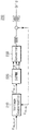
- FIG. 1 is a view showing a configuration diagram of a conventional ESS-PCS.
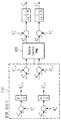
- FIG. 2 is a view showing an example of the configuration of the power storage device for energy storage according to an embodiment of the present invention.
- FIG. 3 is a diagram illustrating an example of determining a control reference voltage and a compensation value of a voltage compensator according to an exemplary embodiment of the present invention.
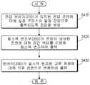
- FIG. 4 is a flowchart illustrating an operation of a power conversion method for energy storage according to an exemplary embodiment of the present invention.
- FIG. 5 is a view showing an example of comparing the output results of the ESS-PCS and the conventional ESS-PCS according to an embodiment of the present invention.
- first and second may be used to describe various components, but the components should not be limited by the terms. The terms are used only for the purpose of distinguishing one component from another.
- the first component may be referred to as the second component, and similarly, the second component may also be referred to as the first component.
- FIG. 2 is a view showing an example of the configuration of the power storage device for energy storage according to an embodiment of the present invention.
- the energy storage power converter 200 includes a voltage compensator 210 for compensating a voltage to be output at a constant voltage having a predetermined frequency with respect to a voltage power source input from the outside. ; A pulse width modulator 220 for outputting a pulse width modulated using a space vector with respect to a power compensated voltage; And a converter 230 for converting the pulse width modulated AC power into DC power.
- the voltage compensator 210 operates with a time constant of several hundred milliseconds (ms) or more.
- the voltage compensator 210 calculates an output voltage reference value by compensating a difference between the reference voltage and the power conditioning control (PCC) voltage.
- PCC power conditioning control
- the voltage compensator 210 outputs the PCC voltage to resonate within a predetermined range even when a load varying in a period of tens to hundreds of milliseconds (ms) is connected.
- the voltage compensator 210 as shown in Fig. 3, the normal d-axis voltage reference value ( ) Or normal q-axis voltage threshold ( ), But differently depending on the vector conversion method.
- 3 is a diagram illustrating an example of determining a control reference voltage and a compensation value of a voltage compensator according to an exemplary embodiment of the present invention.
- the voltage compensator 210 controls the normal d-axis voltage with respect to the control reference voltage
- the voltage compensator 210 does not use the q-axis voltage reference value and the compensation term, and the d-axis and q-axis are respectively '0' or separate for the reverse phase. It is controlled by the reference value of.
- the voltage compensator 210 determines a value to be compensated for the compensation term according to the voltage difference between the output terminal voltage and the reference voltage, and calculates it by integrating the voltage difference with respect to the voltage compensation value, Therefore, it is calculated in a way that increases or decreases constantly.
- the voltage compensator 210 sets the compensation term such that the voltage follows the reference value over the compensation term for several seconds.
- FIG. 4 is a flowchart illustrating an operation of a power conversion method for energy storage according to an exemplary embodiment of the present invention.
- the power storage device 200 for energy storage compensates a voltage such that the voltage compensator 210 is output at a constant voltage having a predetermined frequency with respect to a voltage power source input from the outside. (S410).
- the voltage compensator 210 operates with a time constant of several hundred milliseconds (ms) or more.
- the voltage compensator 210 calculates an output voltage reference value by compensating a difference between the reference voltage and the power conditioning control (PCC) voltage.
- PCC power conditioning control
- the voltage compensator 210 outputs the PCC voltage to resonate within a predetermined range even when a load varying in a period of tens to hundreds of milliseconds (ms) is connected.
- the voltage compensator 210 as shown in Fig. 3, the normal d-axis voltage reference value ( ) Or normal q-axis voltage threshold ( ), But differently depending on the vector conversion method.
- the voltage compensator 210 does not use the q-axis voltage reference value and the compensation term when controlling the normal division d-axis voltage with respect to the control reference voltage, as shown in FIG. Each axis is controlled by '0' or separate reference value.
- the voltage compensator 210 determines a compensation value based on the voltage difference between the output terminal voltage and the reference voltage with respect to the compensation term, and calculates the voltage compensator by integrating the voltage difference with respect to the voltage compensation value, or the voltage difference. It is calculated in a manner that increases or decreases constantly according to the sign of.
- the voltage compensator 210 sets the compensation term so that the voltage follows the reference value over the compensation term for several seconds.
- the pulse width modulator 220 outputs the pulse width modulated using the space vector with respect to the power compensated voltage (S420).
- the pulse width modulator 220 outputs a pulse width modulated d-axis voltage () by compensating for the normal d-axis voltage reference value () by using a space vector as shown in FIG. 3.
- a pulse width modulated q-axis voltage is output by compensating the normal q-axis voltage reference value.
- the converter 230 converts the pulse width modulated AC power into DC power and outputs the converted DC power (S430).
- the converter 230 outputs the d-axis current () through the DC conversion process for the d-axis voltage () received from the pulse width modulator 220, or through the DC conversion process for the q-axis voltage () Outputs the q-axis current ().
- the energy storage power conversion apparatus 200 has a stable PCC voltage, output current, active power, and reactive power as compared to the conventional ESS-PCS controller as shown in FIG. 5.
- outputs 5 is a view showing an example of comparing the output results of the ESS-PCS and the conventional ESS-PCS according to an embodiment of the present invention.
- the output characteristics according to the PCS control method are shown in FIG. 5 under a constant wind condition. As shown in FIG.
- the PCC voltage of the PCS fluctuates to a constant frequency out of the stable region due to the sensitive response of the controller.
- the ESS-PCS of the present invention is within the stable PCC voltage of the PCS. It can be seen that the value is almost constant.
- the present invention when there is a large load using a squirrel inductor in a small system using an energy storage system (ESS), the shunt inductor and the ESS-power converter (PCS) are mutually interfered with each other.
- the present invention provides a power storage device for energy storage that can maintain a constant system voltage while decreasing a voltage fluctuation range.
- the present invention when there is a large load in a small system using an energy storage system (ESS), in order to prevent the voltage and frequency of the system from continuously resonating by mutual interference between the large load and the ESS-power converter (PCS).
- ESS energy storage system
- PCS ESS-power converter
- the present invention can be applied to a power conversion device and method for energy storage that can maintain a constant system voltage while reducing voltage fluctuations.
Landscapes
- Engineering & Computer Science (AREA)
- Power Engineering (AREA)
- Physics & Mathematics (AREA)
- Electromagnetism (AREA)
- General Physics & Mathematics (AREA)
- Radar, Positioning & Navigation (AREA)
- Automation & Control Theory (AREA)
- Supply And Distribution Of Alternating Current (AREA)
Abstract
본 발명은 에너지 저장 시스템(ESS)을 사용하는 소규모 계통에서 대형 부하가 있을 경우, 대형 부하와 ESS-전력 변환 장치(PCS) 간의 상호 간섭에 의해서 계통의 전압 및 주파수가 계속 공진하는 것을 방지하기 위해 전압 변동폭을 작게 하면서 계통 전압을 일정하게 유지할 수 있도록 하는 에너지 저장용 전력 변환 장치 및 방법에 관한 것이다. 본 발명에 따른 에너지 저장용 전력 변환 장치는, 전압 전원에 대해 일정 주파수를 갖는 일정 전압으로 출력되도록 전압을 보상하는 전압 보상기; 상기 전압이 보상된 전원에 대해 공간 벡터를 이용해 펄스폭 변조하여 출력하는 펄스폭 변조부; 및 상기 펄스폭 변조된 교류 전원에 대해 직류 전원으로 변환하는 컨버터를 포함하는 것을 특징으로 한다.
Description
본 발명은 에너지 저장 시스템(Energy Storage System, 이하 ESS)을 사용하는 소규모 계통에서 대형 부하가 있을 경우, 대형 부하와 ESS-전력 변환 장치(Power Conditioning System, 이하 PCS) 간의 상호 간섭에 의해서 계통의 전압 및 주파수가 계속 공진하는 것을 방지하기 위해 전압 변동폭을 작게 하면서 계통 전압을 일정하게 유지할 수 있도록 하는 에너지 저장용 전력 변환 장치 및 방법에 관한 것이다.
최근에 환경 파괴, 자원 고갈 등이 문제되면서, 전력을 저장하고, 저장된 전력을 효율적으로 활용할 수 있는 시스템에 대한 관심이 높아지고 있다. 또한, 이와 함께 발전 과정에서 공해를 유발하지 않는 신재생 에너지에 대한 관심도 높아지고 있다.
에너지 저장 시스템은 이러한 신재생 에너지, 전력을 저장한 배터리, 그리고 기존의 계통 전력을 연계시키는 시스템이다. 이러한 에너지 저장 시스템은 부하의 전력 소비량에 따라서 다양한 용량을 가질 수 있다. 따라서 대용량의 전력을 공급하기 위하여 에너지 저장 시스템은 병렬로 연결된 복수의 전원과 연결되도록 구성될 수 있다.
한편, 디젤 발전기에 의해서 전원을 공급받는 중소규모 섬지역에서 디젤 발전기 대신 신재생 에너지와 에너지 저장 시스템(ESS)을 결합하여 전원을 공급하려는 움직임이 증가하고 있다. 또한, 해외의 경우, 장거리 송전선로를 사용하여 초원, 사막, 정글, 그리고 섬 등을 대규모 계통에 연계시키는 것보다 독립형 전원을 구축하는 것이 더욱 경제적이다.
그런데, 신재생 에너지와 에너지 저장 시스템(ESS)을 결합하여 전원을 공급하려면 도 1에 도시된 바와 같이 전압 제어기와 전류 제어기 및 PWM 발생기로 이루어진 전력 변환 시스템(Power Conditioning System)이 필요하다.
그러나, 종래의 ESS-PCS는 거대 계통에 맞도록 설계되었기 때문에 소규모 계통에서 전체 부하에 전원을 공급해야 할 경우 부하의 잦은 변동이나 농형 유도기 부하에서 계통 전압이 지속적으로 흔들거리는 문제점이 있다. 즉, 도 1에서 전류 제어기는 수백 Hz의 제어 주파수로 PCS 출력 전류를 제어하고, 전압 제어기는 수십 Hz의 주파수로 PCC 전압을 제어하는데, 수ms 내지 수십ms의 주기로 변동하는 부하가 연결될 경우에 PCC 전압이 안정적인 범위를 초과하여 지속적으로 공진하게 되는 문제점이 있다.
또한, 소규모 계통 운영자의 입장에서는 계통의 전압을 일정하게 유지하기 위해서 별도의 장치 또는 제어가 필요하다는 문제점이 있다.
전술한 문제점을 해결하기 위한 본 발명의 목적은, 에너지 저장 시스템(ESS)을 사용하는 소규모 계통에서 대형 부하가 있을 경우, 대형 부하와 ESS-전력 변환 장치(PCS) 간의 상호 간섭에 의해서 계통의 전압 및 주파수가 계속 공진하는 것을 방지하기 위해 전압 변동폭을 작게 하면서 계통 전압을 일정하게 유지할 수 있도록 하는 에너지 저장용 전력 변환 장치 및 방법을 제공함에 있다.
전술한 목적을 달성하기 위한 본 발명에 따른 에너지 저장용 전력 변환 장치는, 전압 전원에 대해 일정 주파수를 갖는 일정 전압으로 출력되도록 전압을 보상하는 전압 보상기; 상기 전압이 보상된 전원에 대해 공간 벡터를 이용해 펄스폭 변조하여 출력하는 펄스폭 변조부; 및 상기 펄스폭 변조된 교류 전원에 대해 직류 전원으로 변환하는 컨버터를 포함하는 것을 특징으로 한다.
또한, 상기 전압 보상기는, 기준 전압과 PCC(Power Conditioning Control) 전압의 차이를 보상하여 출력 전압 기준값을 산출하게 된다.
또한, 상기 전압 보상기는, 수십 내지 수백 밀리세컨드(ms)의 주기로 변동하는 부하가 연결되어도 PCC 전압이 일정 범위 내에서 공진하도록 출력하게 된다.
또한, 상기 전압 보상기는, 제어 기준 전압에 대해 정상분 d축 전압 기준값 또는 정상분 q축 전압 기준값에 따라서 제어하되, 벡터 변환 방식에 따라 다르게 제어하게 된다.
또한, 상기 전압 보상기는, 제어 기준 전압에 대한 정상분 d축 전압을 제어할 경우 q축 전압 기준값과 보상항은 사용하지 않고, 역상분에 대해 d축과 q축을 각각 '0' 또는 별도의 기준값으로 제어하게 된다.
또한, 상기 전압 보상기는, 상기 보상항에 대해 출력단 전압과 기준전압의 전압차에 따라 보상하는 값을 결정하되, 전압 보상값에 대해 전압차를 적분하는 방식으로 산출하거나, 전압차의 부호에 따라 일정하게 증가 또는 감소하는 방식으로 산출하게 된다.
그리고, 상기 전압 보상기는, 상기 보상항에 대해 전압이 수초 간에 걸쳐서 기준값을 추종하도록 상기 보상항을 설정하게 된다.
한편, 전술한 목적을 달성하기 위한 본 발명에 따른 에너지 저장용 전력 변환 방법은, 전압 보상기와 펄스폭 변조부 및 컨버터를 포함하는 장치의 에너지 저장용 전력 변환 방법에 있어서, (a) 상기 전압 보상기가 전압 전원에 대해 일정 주파수를 갖는 일정 전압으로 출력되도록 전압을 보상하는 단계; (b) 상기 펄스폭 변조부가 상기 전압이 보상된 전원에 대해 공간 벡터를 이용해 펄스폭 변조하여 출력하는 단계; 및 (c) 상기 컨버터가 상기 펄스폭 변조된 교류 전원에 대해 직류 전원으로 변환하는 단계를 포함하는 것을 특징으로 한다.
또한, 상기 (a) 단계는, 상기 전압 보상기가, 기준 전압과 PCC(Power Conditioning Control) 전압의 차이를 보상하여 출력 전압 기준값을 산출하게 된다.
또한, 상기 (a) 단계는, 상기 전압 보상기가, 수십 내지 수백 밀리세컨드(ms)의 주기로 변동하는 부하가 연결되어도 PCC 전압이 일정 범위 내에서 공진하도록 출력하게 된다.
또한, 상기 (a) 단계는, 상기 전압 보상기가, 제어 기준 전압에 대해 정상분 d축 전압 기준값 또는 정상분 q축 전압 기준값에 따라 제어하되, 벡터 변환 방식에 따라 다르게 제어하게 된다.
또한, 상기 (a) 단계는, 상기 전압 보상기가, 제어 기준 전압에 대한 정상분 d축 전압을 제어할 경우 q축 전압 기준값과 보상항은 사용하지 않고, 역상분에 대해 d축과 q축을 각각 '0' 또는 별도의 기준값으로 제어하게 된다.
또한, 상기 (a) 단계는, 상기 전압 보상기가, 상기 보상항에 대해 출력단 전압과 기준전압의 전압차에 따라 보상하는 값을 결정하되, 전압 보상값에 대해 전압차를 적분하는 방식으로 산출하거나, 전압차의 부호에 따라 일정하게 증가 또는 감소하는 방식으로 산출하게 된다.
그리고, 상기 (a) 단계는, 상기 전압 보상기가, 상기 보상항에 대해 전압이 수초 간에 걸쳐서 기준값을 추종하도록 상기 보상항을 설정하게 된다.
본 발명에 의하면, 소규모 계통 운영자의 입장에서 계통의 전압을 일정하게 유지하기 위해서 별도의 장치 또는 제어가 필요하지 않게 된다.
또한, 부하의 잦은 변동에도 계통 전압을 일정하게 유지할 수 있기 때문에, 소규모 계통에서 수용가에 안정적인 전압을 공급할 수 있다.
따라서, 수용가에서 사용하는 전기장치의 사용수명이 증가하게 되는 효과가 있다.
도 1은 종래의 ESS-PCS 구성도를 나타낸 도면이다.
도 2는 본 발명의 실시예에 따른 에너지 저장용 전력 변환 장치의 구성 예를 나타낸 도면이다.
도 3은 본 발명의 실시예에 따른 전압 보상기의 제어 기준 전압과 보상 값을 결정하는 예를 나타낸 도면이다.
도 4는 본 발명의 실시예에 따른 에너지 저장용 전력 변환 방법을 설명하기 위한 동작 흐름도를 나타낸 도면이다.
도 5는 본 발명의 실시예에 따른 ESS-PCS와 종래의 ESS-PCS의 출력 결과를 비교한 예를 나타낸 도면이다.
본 발명은 다양한 변경을 가할 수 있고 여러 가지 실시예를 가질 수 있는 바, 특정 실시예들을 도면에 예시하고 상세한 설명에 상세하게 설명하고자 한다. 그러나, 이는 본 발명을 특정한 실시 형태에 대해 한정하려는 것이 아니며, 본 발명의 사상 및 기술 범위에 포함되는 모든 변경, 균등물 내지 대체물을 포함하는 것으로 이해되어야 한다. 각 도면을 설명하면서 유사한 참조부호를 유사한 구성요소에 대해 사용하였다.
제1, 제2 등의 용어는 다양한 구성요소들을 설명하는데 사용될 수 있지만, 상기 구성요소들은 상기 용어들에 의해 한정되어서는 안 된다. 상기 용어들은 하나의 구성요소를 다른 구성요소로부터 구별하는 목적으로만 사용된다. 예를 들어, 본 발명의 권리 범위를 벗어나지 않으면서 제1 구성요소는 제2 구성요소로 명명될 수 있고, 유사하게 제2 구성요소도 제1 구성요소로 명명될 수 있다. 및/또는 이라는 용어는 복수의 관련된 기재된 항목들의 조합 또는 복수의 관련된 기재된 항목들 중의 어느 항목을 포함한다.
어떤 구성요소가 다른 구성요소에 "연결되어" 있다거나 "접속되어"있다고 언급된 때에는, 그 다른 구성요소에 직접적으로 연결되어 있거나 또는 접속되어 있을 수도 있지만, 중간에 다른 구성요소가 존재할 수도 있다고 이해되어야 할 것이다. 반면에, 어떤 구성요소가 다른 구성요소에 "직접 연결되어"있다거나 "직접 접속되어"있다고 언급된 때에는, 중간에 다른 구성요소가 존재하지 않는 것으로 이해되어야 할 것이다.
본 출원에서 사용한 용어는 단지 특정한 실시예를 설명하기 위해 사용된 것으로, 본 발명을 한정하려는 의도가 아니다. 단수의 표현은 문맥상 명백하게 다르게 뜻하지 않는 한, 복수의 표현을 포함한다. 본 출원에서, "포함하다" 또는 "가지다" 등의 용어는 명세서상에 기재된 특징, 숫자, 단계, 동작, 구성요소, 부품 또는 이들을 조합한 것이 존재함을 지정하려는 것이지, 하나 또는 그 이상의 다른 특징들이나 숫자, 단계, 동작, 구성요소, 부품 또는 이들을 조합한 것들의 존재 또는 부가 가능성을 미리 배제하지 않는 것으로 이해되어야 한다.
이하, 첨부한 도면들을 참조하여, 본 발명의 바람직한 실시예를 보다 상세하게 설명하고자 한다. 이하, 도면상의 동일한 구성 요소에 대해서는 동일한 참조부호를 사용하고 동일한 구성 요소에 대해서 중복된 설명은 생략한다.
도 2는 본 발명의 실시예에 따른 에너지 저장용 전력 변환 장치의 구성 예를 나타낸 도면이다.
도 2를 참조하면, 본 발명의 실시예에 따른 에너지 저장용 전력 변환 장치(200)는, 외부로부터 입력된 전압 전원에 대해 일정 주파수를 갖는 일정 전압으로 출력되도록 전압을 보상하는 전압 보상기(210); 전압이 보상된 전원에 대해 공간 벡터를 이용해 펄스폭 변조하여 출력하는 펄스폭 변조부(220); 및 펄스폭 변조된 교류 전원에 대해 직류 전원으로 변환하는 컨버터(Converter)(230)를 포함한다.
또한, 전압 보상기(210)는, 수백 밀리세컨드(ms) 이상의 시정수로 동작하게 된다.
또한, 전압 보상기(210)는, 기준 전압과 PCC(Power Conditioning Control) 전압의 차이를 보상하여 출력 전압 기준값을 산출하게 된다.
또한, 전압 보상기(210)는, 수십 내지 수백 밀리세컨드(ms)의 주기로 변동하는 부하가 연결되어도 PCC 전압이 일정 범위 내에서 공진하도록 출력하게 된다.
또한, 전압 보상기(210)는, 도 3에 도시된 바와 같이 제어 기준 전압에 대해 정상분 d축 전압 기준값( ) 또는 정상분 q축 전압 기준값(
 )에 따라서 제어하되, 벡터 변환 방식에 따라 다르게 제어하게 된다. 도 3은 본 발명의 실시예에 따른 전압 보상기의 제어 기준 전압과 보상 값을 결정하는 예를 나타낸 도면이다.
또한, 전압 보상기(210)는, 제어 기준 전압에 대한 정상분 d축 전압을 제어할 경우 q축 전압 기준값과 보상항은 사용하지 않고, 역상분에 대해 d축과 q축을 각각 '0' 또는 별도의 기준값으로 제어하게 된다.
또한, 전압 보상기(210)는, 보상항에 대해 출력단 전압과 기준전압의 전압차에 따라 보상하는 값을 결정하되, 전압 보상값에 대해 전압차를 적분하는 방식으로 산출하거나, 전압차의 부호에 따라 일정하게 증가 또는 감소하는 방식으로 산출하게 된다.
그리고, 전압 보상기(210)는, 보상항에 대해 전압이 수초 간에 걸쳐서 기준값을 추종하도록 상기 보상항을 설정하게 된다.
도 4는 본 발명의 실시예에 따른 에너지 저장용 전력 변환 방법을 설명하기 위한 동작 흐름도를 나타낸 도면이다.
도 4를 참조하면, 본 발명의 실시예에 따른 에너지 저장용 전력 변환 장치(200)는, 전압 보상기(210)가 외부로부터 입력된 전압 전원에 대해 일정 주파수를 갖는 일정 전압으로 출력되도록 전압을 보상한다(S410).
여기서, 전압 보상기(210)는, 수백 밀리세컨드(ms) 이상의 시정수로 동작하게 된다.
또한, 전압 보상기(210)는, 기준 전압과 PCC(Power Conditioning Control) 전압의 차이를 보상하여 출력 전압 기준값을 산출하게 된다.
또한, 전압 보상기(210)는, 수십 내지 수백 밀리세컨드(ms)의 주기로 변동하는 부하가 연결되어도 PCC 전압이 일정 범위 내에서 공진하도록 출력하게 된다.
또한, 전압 보상기(210)는, 도 3에 도시된 바와 같이 제어 기준 전압에 대해 정상분 d축 전압 기준값( ) 또는 정상분 q축 전압 기준값(
 )에 따라서 제어하되, 벡터 변환 방식에 따라 다르게 제어하게 된다.
또한, 전압 보상기(210)는, 도 3에 도시된 바와 같이 제어 기준 전압에 대한 정상분 d축 전압을 제어할 경우 q축 전압 기준값과 보상항은 사용하지 않고, 역상분에 대해 d축과 q축을 각각 '0' 또는 별도의 기준값으로 제어하게 된다.
또한, 도 3에서 전압 보상기(210)는, 보상항에 대해 출력단 전압과 기준전압의 전압차에 따라 보상하는 값을 결정하되, 전압 보상값에 대해 전압차를 적분하는 방식으로 산출하거나, 전압차의 부호에 따라 일정하게 증가 또는 감소하는 방식으로 산출하게 된다.
그리고, 전압 보상기(210)는, 보상항에 대해 전압이 수초 간에 걸쳐서 기준값을 추종하도록 보상항을 설정하게 된다.
이어, 펄스폭 변조부(220)가 전압이 보상된 전원에 대해 공간 벡터를 이용해 펄스폭 변조하여 출력한다(S420).
즉, 펄스폭 변조부(220)는 도 3에 도시된 바와 같이 공간 벡터(space vector)를 이용하여 정상분 d축 전압 기준값()을 보상하여 펄스폭 변조한 d축 전압()을 출력하고, 정상분 q축 전압 기준값()을 보상하여 펄스폭 변조한 q축 전압()을 출력한다.
이어, 컨버터(230)가 펄스폭 변조된 교류 전원에 대해 직류 전원으로 변환하여 출력한다(S430).
즉, 컨버터(230)는 펄스폭 변조부(220)로부터 전달받은 d축 전압()에 대해 직류 변환 과정을 거쳐 d축 전류()를 출력하거나, q축 전압()에 대해 직류 변환 과정을 거쳐 q축 전류()를 출력하게 된다.
따라서, 본 발명의 실시예에 따른 에너지 저장용 전력 변환 장치(200)는, 도 5에 도시된 바와 같이 기존의 ESS-PCS 제어기에 비교하여 PCC 전압과 출력전류, 유효전력 및 무효 전력이 안정한 형태로 출력하는 것을 알 수 있다. 도 5는 본 발명의 실시예에 따른 ESS-PCS와 종래의 ESS-PCS의 출력 결과를 비교한 예를 나타낸 도면이다. 예를 들어, 1 MW ESS PCS와 250 KW 농형 유도기 계통 직입형 풍력 발전기로 시스템을 구성할 경우, 일정한 풍력 조건에서 PCS 제어 방식에 따른 출력 특성이 도 5에 도시된 바와 같이 나타남을 알 수 있다. 도 5에서 알 수 있듯이 기존의 ESS-PCS의 경우에는 제어기의 민감한 반응으로 PCS의 PCC 전압이 안정 영역을 벗어나 일정한 주파수로 변동하였으나, 본 발명의 ESS-PCS는 PCS의 PCC 전압이 안정한 영역 내에서 거의 일정한 값을 유지하는 것을 알 수 있다.
전술한 바와 같이 본 발명에 의하면, 에너지 저장 시스템(ESS)을 사용하는 소규모 계통에서 농형 유도기를 사용하는 대형 부하가 있을 경우, 농형 유도기와 ESS-전력 변환 장치(PCS)의 상호 간섭에 의해서 계통의 전압 및 주파수가 계속 공진하는 것을 방지하기 위해 전압 변동폭을 작게 하면서 계통 전압을 일정하게 유지할 수 있도록 하는 에너지 저장용 전력 변환 장치를 제공함에 있다.
본 발명이 속하는 기술분야의 당업자는 본 발명이 그 기술적 사상이나 필수적 특징을 변경하지 않고서 다른 구체적인 형태로 실시될 수 있으므로, 이상에서 기술한 실시예들은 모든 면에서 예시적인 것이며 한정적인 것이 아닌 것으로서 이해해야만 한다. 본 발명의 범위는 상기 상세한 설명보다는 후술하는 특허청구범위에 의하여 나타내어지며, 특허청구범위의 의미 및 범위 그리고 그 등가개념으로부터 도출되는 모든 변경 또는 변형된 형태가 본 발명의 범위에 포함되는 것으로 해석되어야 한다.
본 발명은 에너지 저장 시스템(ESS)을 사용하는 소규모 계통에서 대형 부하가 있을 경우, 대형 부하와 ESS-전력 변환 장치(PCS) 간의 상호 간섭에 의해서 계통의 전압 및 주파수가 계속 공진하는 것을 방지하기 위해 전압 변동폭을 작게 하면서 계통 전압을 일정하게 유지할 수 있도록 하는 에너지 저장용 전력 변환 장치 및 방법에 적용할 수 있다.
Claims (12)
- 전압 전원에 대해 일정 주파수를 갖는 일정 전압으로 출력되도록 전압을 보상하는 전압 보상기;상기 전압이 보상된 전원에 대해 공간 벡터를 이용해 펄스폭 변조하여 출력하는 펄스폭 변조부; 및상기 펄스폭 변조된 교류 전원에 대해 직류 전원으로 변환하는 컨버터;를 포함하는 에너지 저장용 전력 변환 장치.
- 청구항 1에 있어서,상기 전압 보상기는, 기준 전압과 PCC(Power Conditioning Control) 전압의 차이를 보상하여 출력 전압 기준값을 산출하는 것을 특징으로 하는 에너지 저장용 전력 변환 장치.
- 청구항 1에 있어서,상기 전압 보상기는, 수십 내지 수백 밀리세컨드(ms)의 주기로 변동하는 부하가 연결되어도 PCC 전압이 일정 범위 내에서 공진하도록 출력하는 것을 특징으로 하는 에너지 저장용 전력 변환 장치.
- 청구항 1에 있어서,상기 전압 보상기는, 제어 기준 전압에 대해 정상분 d축 전압 기준값() 또는 정상분 q축 전압 기준값(
 )에 따라서 제어하되, 벡터 변환 방식에 따라 다르게 제어하는 것을 특징으로 하는 에너지 저장용 전력 변환 장치.
- 청구항 1에 있어서,상기 전압 보상기는, 제어 기준 전압에 대한 정상분 d축 전압을 제어할 경우 q축 전압 기준값과 보상항은 사용하지 않고, 역상분에 대해 d축과 q축을 각각 '0' 또는 별도의 기준값으로 제어하는 것을 특징으로 하는 에너지 저장용 전력 변환 장치.
- 전압 보상기와 펄스폭 변조부 및 컨버터를 포함하는 장치의 에너지 저장용 전력 변환 방법에 있어서,(a) 상기 전압 보상기가 전압 전원에 대해 일정 주파수를 갖는 일정 전압으로 출력되도록 전압을 보상하는 단계;(b) 상기 펄스폭 변조부가 상기 전압이 보상된 전원에 대해 공간 벡터를 이용해 펄스폭 변조하여 출력하는 단계; 및(c) 상기 컨버터가 상기 펄스폭 변조된 교류 전원에 대해 직류 전원으로 변환하는 단계;를 포함하는 에너지 저장용 전력 변환 방법.
- 청구항 6에 있어서,상기 (a) 단계는, 상기 전압 보상기가, 기준 전압과 PCC(Power Conditioning Control) 전압의 차이를 보상하여 출력 전압 기준값을 산출하는 것을 특징으로 하는 에너지 저장용 전력 변환 방법.
- 청구항 6에 있어서,상기 (a) 단계는, 상기 전압 보상기가, 수십 내지 수백 밀리세컨드(ms)의 주기로 변동하는 부하가 연결되어도 PCC 전압이 일정 범위 내에서 공진하도록 출력하는 것을 특징으로 하는 에너지 저장용 전력 변환 방법.
- 청구항 6에 있어서,상기 (a) 단계는, 상기 전압 보상기가, 제어 기준 전압에 대해 정상분 d축 전압 기준값() 또는 정상분 q축 전압 기준값(
 )에 따라 제어하되, 벡터 변환 방식에 따라 다르게 제어하는 것을 특징으로 하는 에너지 저장용 전력 변환 방법.
- 청구항 6에 있어서,상기 (a) 단계는, 상기 전압 보상기가, 제어 기준 전압에 대한 정상분 d축 전압을 제어할 경우 q축 전압 기준값과 보상항은 사용하지 않고, 역상분에 대해 d축과 q축을 각각 '0' 또는 별도의 기준값으로 제어하는 것을 특징으로 하는 에너지 저장용 전력 변환 방법.
- 청구항 10에 있어서,상기 (a) 단계는, 상기 전압 보상기가, 상기 보상항에 대해 출력단 전압과 기준전압의 전압차에 따라 보상하는 값을 결정하되, 전압 보상값에 대해 전압차를 적분하는 방식으로 산출하거나, 전압차의 부호에 따라 일정하게 증가 또는 감소하는 방식으로 산출하는 것을 특징으로 하는 에너지 저장용 전력 변환 방법.
- 청구항 10에 있어서,상기 (a) 단계는, 상기 전압 보상기가, 상기 보상항에 대해 전압이 수초 간에 걸쳐서 기준값을 추종하도록 상기 보상항을 설정하는 것을 특징으로 하는 에너지 저장용 전력 변환 방법.
Applications Claiming Priority (2)
| Application Number | Priority Date | Filing Date | Title |
|---|---|---|---|
| KR1020130167103A KR101532661B1 (ko) | 2013-12-30 | 2013-12-30 | 에너지 저장용 전력 변환 장치 및 방법 |
| KR10-2013-0167103 | 2013-12-30 |
Publications (1)
| Publication Number | Publication Date |
|---|---|
| WO2015102397A1 true WO2015102397A1 (ko) | 2015-07-09 |
Family
ID=53493672
Family Applications (1)
| Application Number | Title | Priority Date | Filing Date |
|---|---|---|---|
| PCT/KR2014/013084 Ceased WO2015102397A1 (ko) | 2013-12-30 | 2014-12-30 | 에너지 저장용 전력 변환 장치 및 방법 |
Country Status (2)
| Country | Link |
|---|---|
| KR (1) | KR101532661B1 (ko) |
| WO (1) | WO2015102397A1 (ko) |
Families Citing this family (1)
| Publication number | Priority date | Publication date | Assignee | Title |
|---|---|---|---|---|
| CN115864483B (zh) * | 2022-11-22 | 2025-07-22 | 国网江苏省电力有限公司常州供电分公司 | 基于直流配电的高速公路能源保障系统的控制方法 |
Citations (5)
| Publication number | Priority date | Publication date | Assignee | Title |
|---|---|---|---|---|
| JPH09182441A (ja) * | 1995-12-28 | 1997-07-11 | Toshiba Corp | 三相整流装置 |
| US5892674A (en) * | 1996-02-16 | 1999-04-06 | Hitachi, Ltd. | Method and apparatus for power converting AC into DC or DC into AC by converter having common phase connection |
| JP2000217367A (ja) * | 1999-01-25 | 2000-08-04 | Hitachi Ltd | 電流制御回路、インバ―タ制御装置、インバ―タ装置、および電力変換装置 |
| US20080013347A1 (en) * | 2003-05-12 | 2008-01-17 | Ballard Power Systems Corporation | Method and apparatus for adjusting wakeup time in electrical power converter systems and transformer isolation |
| US7492616B2 (en) * | 2005-03-25 | 2009-02-17 | Lineage Power Corporation | Modulation controller, method of controlling and three phase converter system employing the same |
-
2013
- 2013-12-30 KR KR1020130167103A patent/KR101532661B1/ko active Active
-
2014
- 2014-12-30 WO PCT/KR2014/013084 patent/WO2015102397A1/ko not_active Ceased
Patent Citations (5)
| Publication number | Priority date | Publication date | Assignee | Title |
|---|---|---|---|---|
| JPH09182441A (ja) * | 1995-12-28 | 1997-07-11 | Toshiba Corp | 三相整流装置 |
| US5892674A (en) * | 1996-02-16 | 1999-04-06 | Hitachi, Ltd. | Method and apparatus for power converting AC into DC or DC into AC by converter having common phase connection |
| JP2000217367A (ja) * | 1999-01-25 | 2000-08-04 | Hitachi Ltd | 電流制御回路、インバ―タ制御装置、インバ―タ装置、および電力変換装置 |
| US20080013347A1 (en) * | 2003-05-12 | 2008-01-17 | Ballard Power Systems Corporation | Method and apparatus for adjusting wakeup time in electrical power converter systems and transformer isolation |
| US7492616B2 (en) * | 2005-03-25 | 2009-02-17 | Lineage Power Corporation | Modulation controller, method of controlling and three phase converter system employing the same |
Also Published As
| Publication number | Publication date |
|---|---|
| KR101532661B1 (ko) | 2015-06-30 |
Similar Documents
| Publication | Publication Date | Title |
|---|---|---|
| WO2012043919A1 (en) | Power conversion system for energy storage system and controlling method of the same | |
| WO2022114624A1 (ko) | 태양광 발전 시스템 | |
| KR102181321B1 (ko) | 전력변환장치 | |
| WO2017018584A1 (ko) | 마이크로그리드의 멀티 주파수 제어 시스템 및 방법 | |
| WO2019017574A1 (ko) | 마이크로그리드의 제어 및 운영 연구를 위한 유연한 테스트 플랫폼 | |
| WO2019059491A1 (ko) | Ess 출력 제어 방법 | |
| WO2012005464A2 (ko) | 배터리 전원 공급 장치 및 그 전력 제어 방법 | |
| WO2021040165A1 (ko) | 태양광 발전설비의 전력제어를 위한 게이트웨이장치 | |
| WO2015072652A1 (ko) | 다중 배터리 충전기 및 그 제어방법 | |
| WO2017030228A1 (ko) | Btb 컨버터 기반 다수 마이크로그리드의 멀티 주파수 제어 시스템 및 방법 | |
| WO2018230831A1 (ko) | 에너지 저장 시스템 | |
| WO2020091168A1 (ko) | 전력변환장치 | |
| WO2018117529A1 (ko) | 산업단지 마이크로그리드 시스템 | |
| US20160082851A1 (en) | Charging system and charging method | |
| WO2011139023A2 (ko) | 태양광 발전을 위한 dc/dc 컨버터 장치, 인버터 시스템 및 이를 포함하는 태양광 발전 시스템 | |
| KR20160001883A (ko) | 마이크로그리드 시스템, 그 제어장치 및 제어방법 | |
| WO2020045759A1 (ko) | 태양광 연계 에너지 저장 시스템용 dc-dc 컨버터 및 그 제어방법 | |
| WO2019151656A1 (ko) | Ess 출력 분배 방법 및 장치 | |
| WO2015102398A1 (ko) | 풍력 발전기용 에너지 저장 시스템 및 방법 | |
| WO2015102397A1 (ko) | 에너지 저장용 전력 변환 장치 및 방법 | |
| US9306394B2 (en) | Distributed load current sensing system | |
| EP4629461A1 (en) | Power supply system | |
| WO2024210310A1 (ko) | 직류-직류 컨버터의 플라잉 커패시터 전압 조절 장치 및 그 제어 방법 | |
| JPH07131936A (ja) | 直流送電制御装置 | |
| US20220385071A1 (en) | Flexible Interconnection Device and Method for Controlling a Flexible Interconnection Device |
Legal Events
| Date | Code | Title | Description |
|---|---|---|---|
| 121 | Ep: the epo has been informed by wipo that ep was designated in this application |
Ref document number: 14876980 Country of ref document: EP Kind code of ref document: A1 |
|
| NENP | Non-entry into the national phase |
Ref country code: DE |
|
| 122 | Ep: pct application non-entry in european phase |
Ref document number: 14876980 Country of ref document: EP Kind code of ref document: A1 |