WO2015098826A1 - Compressor and supercharger - Google Patents
Compressor and supercharger Download PDFInfo
- Publication number
- WO2015098826A1 WO2015098826A1 PCT/JP2014/083891 JP2014083891W WO2015098826A1 WO 2015098826 A1 WO2015098826 A1 WO 2015098826A1 JP 2014083891 W JP2014083891 W JP 2014083891W WO 2015098826 A1 WO2015098826 A1 WO 2015098826A1
- Authority
- WO
- WIPO (PCT)
- Prior art keywords
- guide tube
- scroll
- compressor
- ring
- impeller
- Prior art date
Links
Images


Classifications
-
- F—MECHANICAL ENGINEERING; LIGHTING; HEATING; WEAPONS; BLASTING
- F04—POSITIVE - DISPLACEMENT MACHINES FOR LIQUIDS; PUMPS FOR LIQUIDS OR ELASTIC FLUIDS
- F04D—NON-POSITIVE-DISPLACEMENT PUMPS
- F04D29/00—Details, component parts, or accessories
- F04D29/66—Combating cavitation, whirls, noise, vibration or the like; Balancing
- F04D29/68—Combating cavitation, whirls, noise, vibration or the like; Balancing by influencing boundary layers
- F04D29/681—Combating cavitation, whirls, noise, vibration or the like; Balancing by influencing boundary layers especially adapted for elastic fluid pumps
- F04D29/685—Inducing localised fluid recirculation in the stator-rotor interface
-
- F—MECHANICAL ENGINEERING; LIGHTING; HEATING; WEAPONS; BLASTING
- F01—MACHINES OR ENGINES IN GENERAL; ENGINE PLANTS IN GENERAL; STEAM ENGINES
- F01D—NON-POSITIVE DISPLACEMENT MACHINES OR ENGINES, e.g. STEAM TURBINES
- F01D21/00—Shutting-down of machines or engines, e.g. in emergency; Regulating, controlling, or safety means not otherwise provided for
- F01D21/04—Shutting-down of machines or engines, e.g. in emergency; Regulating, controlling, or safety means not otherwise provided for responsive to undesired position of rotor relative to stator or to breaking-off of a part of the rotor, e.g. indicating such position
- F01D21/045—Shutting-down of machines or engines, e.g. in emergency; Regulating, controlling, or safety means not otherwise provided for responsive to undesired position of rotor relative to stator or to breaking-off of a part of the rotor, e.g. indicating such position special arrangements in stators or in rotors dealing with breaking-off of part of rotor
-
- F—MECHANICAL ENGINEERING; LIGHTING; HEATING; WEAPONS; BLASTING
- F04—POSITIVE - DISPLACEMENT MACHINES FOR LIQUIDS; PUMPS FOR LIQUIDS OR ELASTIC FLUIDS
- F04D—NON-POSITIVE-DISPLACEMENT PUMPS
- F04D25/00—Pumping installations or systems
- F04D25/02—Units comprising pumps and their driving means
- F04D25/024—Units comprising pumps and their driving means the driving means being assisted by a power recovery turbine
-
- F—MECHANICAL ENGINEERING; LIGHTING; HEATING; WEAPONS; BLASTING
- F04—POSITIVE - DISPLACEMENT MACHINES FOR LIQUIDS; PUMPS FOR LIQUIDS OR ELASTIC FLUIDS
- F04D—NON-POSITIVE-DISPLACEMENT PUMPS
- F04D29/00—Details, component parts, or accessories
- F04D29/40—Casings; Connections of working fluid
- F04D29/42—Casings; Connections of working fluid for radial or helico-centrifugal pumps
- F04D29/4206—Casings; Connections of working fluid for radial or helico-centrifugal pumps especially adapted for elastic fluid pumps
- F04D29/4213—Casings; Connections of working fluid for radial or helico-centrifugal pumps especially adapted for elastic fluid pumps suction ports
-
- F—MECHANICAL ENGINEERING; LIGHTING; HEATING; WEAPONS; BLASTING
- F04—POSITIVE - DISPLACEMENT MACHINES FOR LIQUIDS; PUMPS FOR LIQUIDS OR ELASTIC FLUIDS
- F04D—NON-POSITIVE-DISPLACEMENT PUMPS
- F04D29/00—Details, component parts, or accessories
- F04D29/66—Combating cavitation, whirls, noise, vibration or the like; Balancing
- F04D29/661—Combating cavitation, whirls, noise, vibration or the like; Balancing especially adapted for elastic fluid pumps
- F04D29/663—Sound attenuation
-
- F—MECHANICAL ENGINEERING; LIGHTING; HEATING; WEAPONS; BLASTING
- F05—INDEXING SCHEMES RELATING TO ENGINES OR PUMPS IN VARIOUS SUBCLASSES OF CLASSES F01-F04
- F05D—INDEXING SCHEME FOR ASPECTS RELATING TO NON-POSITIVE-DISPLACEMENT MACHINES OR ENGINES, GAS-TURBINES OR JET-PROPULSION PLANTS
- F05D2220/00—Application
- F05D2220/40—Application in turbochargers
-
- F—MECHANICAL ENGINEERING; LIGHTING; HEATING; WEAPONS; BLASTING
- F05—INDEXING SCHEMES RELATING TO ENGINES OR PUMPS IN VARIOUS SUBCLASSES OF CLASSES F01-F04
- F05D—INDEXING SCHEME FOR ASPECTS RELATING TO NON-POSITIVE-DISPLACEMENT MACHINES OR ENGINES, GAS-TURBINES OR JET-PROPULSION PLANTS
- F05D2240/00—Components
- F05D2240/10—Stators
- F05D2240/14—Casings or housings protecting or supporting assemblies within
Definitions
- the present invention relates to a supercharger that performs supercharging using exhaust gas discharged from a compressor and an exhaust turbine.
- the turbocharger is configured such that a turbine and a compressor are integrally connected by a rotor shaft and are rotatably accommodated in a housing.
- the exhaust gas is supplied into the housing, and the rotor is driven and rotated by rotating the turbine, thereby driving the compressor.
- the compressor sucks air from the outside, pressurizes it with an impeller to form compressed air, and supplies this compressed air to a diesel engine or the like.
- a supercharger there exist some which were described in patent document 1, for example.
- Patent Document 2 discloses a technique for solving such a problem.
- the exhaust turbine supercharger described in Patent Document 2 includes a turbine housing, a compressor housing, and a bearing housing, and a lubricating oil head tank is provided in the bearing housing, and the lubricating oil head tank is positioned closer to the compressor than the turbine blades.
- a compressor-side partition located on the turbine side from the compressor impeller, and an impact-absorbing partition located at a distance from the compressor-side partition to the compressor.
- a turbine side partition is provided on the compressor side from the turbine blades, a compressor side partition is provided on the turbine side, and an interval is provided from the compressor side partition to the compressor side.
- a shock absorbing partition is provided. In this case, the breakage of the scroll cannot be prevented when the impeller bursts.
- This invention solves the subject mentioned above, and aims at providing the compressor and supercharger which can prevent the breakage of the scroll at the time of the burst of an impeller.
- a compressor includes an impeller fixed to a rotor shaft, and a fluid that is disposed on an outer peripheral side of the impeller and that is taken in from an intake port.
- a guide tube that guides the car, a scroll that is disposed on an outer peripheral side of the guide tube and that guides compressed air pressurized by the impeller, and a ring member that is disposed between the guide tube and the scroll Has.
- the impeller when the impeller bursts, the impeller that is scattered outward in the radial direction or a part of the impeller first collides with the guide cylinder, and the impact force is absorbed by damaging the guide cylinder. Thereafter, the impeller or a part of the impeller collides with the ring member, but since the impact force has been reduced in advance, the ring member is not damaged. Therefore, the impeller or part of the impeller is prevented from scattering in the axial direction, and the opening of the mouth is prevented. As a result, it is possible to prevent the scroll from being damaged when the impeller bursts.
- the scroll is bolted to a housing
- the guide cylinder is bolted to the scroll
- the ring member is bolted to the guide cylinder
- the ring member has one end in the axial direction sandwiched between the scroll and the guide tube, and a fastening bolt passes through the guide tube and the shaft in the ring member. Screw into one end of the direction.
- the ring member can be firmly supported.
- the assembling property can be improved and the elastic force can be secured to the ring member.
- the guide cylinder includes a guide cylinder main body having a circulation path in an inner peripheral portion, and a guide ring arranged on the upstream side in the fluid flow direction in the circulation path.
- the guide ring is bolted to the scroll
- the guide tube body is bolted to the guide ring
- the ring member is bolted to the guide ring.
- the ring member is fastened to the guide ring, and the guide tube main body is fastened to the guide ring, and these are inserted into the housing, and the guide ring is fastened to the scroll. it can.
- the guide tube and the scroll are manufactured by casting, and the ring member is manufactured by a general structural rolled steel material.
- the compressor and the turbine described above are integrally connected by a rotor shaft and are rotatably accommodated in a housing.
- the ring member is disposed between the guide cylinder and the scroll, it is possible to prevent the scroll from being damaged when the impeller bursts.
- FIG. 1 is a schematic sectional view showing the supercharger of the first embodiment.
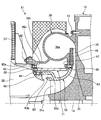
- FIG. 2 is a cross-sectional view of a main part of the supercharger.
- FIG. 3 is a cross-sectional view of a main part showing a supercharger according to the second embodiment.
- FIG. 1 is a schematic cross-sectional view showing a supercharger according to the first embodiment
- FIG. 2 is a main cross-sectional view of the supercharger.
- the supercharger 11 is an exhaust turbine supercharger, for example, a cylinder liner that constitutes a marine diesel engine by being mounted on a marine diesel engine (not shown).
- the compressed air is supplied to an air supply manifold that communicates with the interior of the air supply.
- the turbocharger 11 is configured such that a turbine 12 and a compressor 13 are integrally connected by a rotor shaft 14 and are rotatably accommodated in a housing 15.
- the housing 15 has a hollow shape, the rotor shaft 14 is disposed inside, and is rotatably supported by a thrust bearing 21 and radial bearings 22 and 23.
- the rotor shaft 14 has a turbine disk 24 fixed to one end portion in the axial direction.
- the turbine disk 24 has a plurality of turbine blades 25 having an axial flow type provided at a predetermined interval in the circumferential direction.
- the turbine 12 includes the turbine disk 24 and a plurality of turbine blades 25.
- the housing 15 is provided with an exhaust gas inlet passage 26 and an exhaust gas outlet passage 27 with respect to the turbine blade 25. Further, the housing 15 is provided with a turbine nozzle 28 between the inlet passage 26 and the turbine blade 25, and the axial exhaust gas flow statically expanded by the turbine nozzle 28 is guided to the plurality of turbine blades 25. Thus, the turbine 12 can be driven to rotate.
- the rotor shaft 14 has a compressor impeller 31 having a plurality of blades 31a provided at predetermined intervals in the circumferential direction fixed to the other end in the axial direction.
- the compressor 13 is constituted by the compressor impeller 31.
- the housing 15 is provided with an air intake port 32 and a compressed air discharge port 33 with respect to the compressor impeller 31.
- the housing 15 is provided with an air guide tube 34 between the compressor impeller 31 and the air intake port 32, while a diffuser 35 and a vortex chamber 36 a are provided between the compressor impeller 31 and the compressed air discharge port 33.
- a scroll 36 is provided.
- the air compressed by the compressor impeller 31 is discharged through the diffuser 35 and the scroll 36 (vortex chamber 36a).
- the housing 15 has a silencer 37 attached to the air intake 32.
- the exhaust gas from the marine diesel engine passes through the exhaust gas inlet passage 26 and is statically expanded by the turbine nozzle 28, and the exhaust gas flow in the axial direction is guided to the plurality of turbine blades 25.
- the turbine 12 is driven to rotate through the turbine disk 24 to which the turbine blades 25 are fixed.
- the exhaust gas that has driven the plurality of turbine blades 25 is discharged to the outside from the outlet passage 27.
- the integral compressor impeller 31 rotates and air is sucked through the air intake port 32.
- the sucked air is pressurized by the compressor impeller 31 to become compressed air, which passes through the diffuser 35 and the scroll 36 and is supplied from the compressed air discharge port 33 to the marine diesel engine.
- the rotor shaft 14 is rotatably supported by the housing 15, and the compressor impeller 31 is integrated with the other end portion of the rotor shaft 14. It is fixed to.
- the scroll 36 is disposed on the outer side in the radial direction of the compressor impeller 31, and the outer peripheral portion is fixed to the housing 15 with a bolt 41.
- the scroll 36 has a vortex chamber 36a, and a silencer 37 is fixed to a mounting portion 36b extending to the air intake port 32 side by a bolt 42. Further, the scroll 36 is formed with a mounting flange 36c extending from the mounting portion 36b to the inner peripheral side.
- the air guide tube 34 is formed with a mounting flange 34a extending outward at one end on the air intake port 32 side.
- the air guide tube 34 is connected by a bolt 43 with a mounting flange 34 a overlapping the air intake port 32 side of the mounting flange 36 c of the scroll 36.
- the air guide tube 34 is divided into a mounting flange 34 a side and a main body 34 b side, and is connected by a bolt 45 via a liner 44.
- a ring-shaped guide plate 46 is fixed to the inner peripheral portion by bolts 47, and the turbine nozzle 28 is attached to the guide plate 46.
- the air guide cylinder 34 has a curved shape along the outer peripheral surface of the compressor impeller 31 with the intermediate portion in the axial direction protruding toward the inner peripheral side, and the tip end is in close contact with the inner peripheral portion of the scroll 36 via the O-ring 48. ing.
- a containment ring 51 is disposed between the air guide tube 34 and the scroll 36.
- the containment ring 51 is bolted to the air guide tube 34. That is, the containment ring 51 has a ring shape in which the inner diameter and the outer diameter are constant in the axial direction, and one end in the axial direction is the outer peripheral surface of the mounting flange 36 c in the scroll 36 and the outer periphery of the mounting flange 34 a in the air guide tube 34. It is pinched by the surface.
- the containment ring 51 has one end face in the axial direction in close contact with the mounting flange 34a, and the fastening bolt 52 passes through the mounting flange 34a and is screwed into the one end. Therefore, only the one end part in the axial direction of the containment ring 51 is fixed to the end part on the air intake port 32 side of the air guide tube 34.
- the air guide tube 34 and the scroll 36 are castings manufactured by casting, and the containment ring 51 is a ring member manufactured by a general structural rolled steel (for example, SS400). That is, the air guide tube 34 and the scroll 36 are manufactured with high precision by casting a complicated shape, but the strength against impact is not sufficient.
- the containment ring 51 is manufactured from a general structural rolled steel material with a simple shape. In particular, the containment ring 51 is more ductile than the air guide tube 34 and has sufficient strength against impact.
- the compressor impeller 31 in the turbocharger 11 bursts for some reason, a part of the bursted compressor impeller 31 is scattered outward in the radial direction.
- a part of the compressor impeller 31 is guided to the air. Collide with the cylinder 34. Since the air guide tube 34 is manufactured by casting, the strength against impact is not sufficient, and since the air guide tube 34 has a crushable structure, it is damaged and the impact force of the compressor impeller 31 is absorbed.
- the compressor impeller 31 collides with the containment ring 51. Since the containment ring 51 is made of rolled steel for general structure, it has high ductility and sufficient strength against impact, so that it receives and absorbs the impact force of the compressor impeller 31 without being damaged. . Therefore, the scroll 36 is not damaged, and the compressor impeller 31 is not scattered in the axial direction, so that the silencer 37 is prevented from being damaged and the mouth opening is prevented.
- the turbine 12 and the compressor 13 are integrally connected by the rotor shaft 14 and are rotatably accommodated in the housing 15.
- the scroll 36 which guides the compressed air which was arrange
- the scroll 36 is bolted to the housing 15, the air guide tube 34 is bolted to the scroll 36, and the containment ring 51 is bolted to the air guide tube 34. . Therefore, in a state where the containment ring 51 is fastened to the air guide tube 34, both are inserted into the housing 15 and the air guide tube 34 is fastened to the scroll 36, so that the assembling property can be improved. In this case, the containment ring 51 can be easily fixed by changing only the air guide tube 34 without changing the scroll 36 or the like.
- the containment ring 51 includes an end portion in the axial direction that is sandwiched between the scroll 36 and the air guide tube 34, and the fastening bolt 52 penetrates the air guide tube 34. 51 is screwed into one end portion in the axial direction. Therefore, the containment ring 51 can be firmly supported on the housing 15 side by clamping the containment ring 51 with the scroll 36 and the air guide tube 34.
- the containment ring 51 is fixed to the air guide tube 34 only at one end in the axial direction. Therefore, by using the containment ring 51 as a cantilever support, the bolt fastening portion can be reduced and the assemblability can be improved. Further, the containment ring 51 can have an elastic force, and the compressor impeller 31 can be The impact force at the time of collision can be absorbed.
- the air guide tube 34 and the scroll 36 are cast products manufactured by casting, and the containment ring 51 is a ring member manufactured by using general structural rolled steel. Therefore, if the air guide tube 34 has a crushable structure, the scattered impeller 31 will be properly damaged when it collides, so that the impact force at this time can be absorbed effectively, and the containment ring 51 can be absorbed. When the ductility is ensured, the impact force can be properly absorbed by the elastic force when the scattered compressor impeller 31 collides.
- FIG. 3 is a cross-sectional view of a main part showing a supercharger according to the second embodiment.
- symbol is attached
- the rotor shaft 14 is rotatably supported by the housing 15 by the compressor 61, and the compressor impeller 31 is integrally fixed to the other end portion of the rotor shaft 14.
- the scroll 36 is disposed on the outer side in the radial direction of the compressor impeller 31, and the outer peripheral portion is fixed to the housing 15 with a bolt 41.
- the scroll 36 has a vortex chamber 36a, and a silencer 37 is fixed to a mounting portion 36b extending to the air intake port 32 side by a bolt 42. Further, the scroll 36 is formed with a mounting flange 36c extending from the mounting portion 36b to the inner peripheral side.
- the air guide cylinder 62 is provided with a recirculation flow path (air circulation path) 63 for preventing surging that tends to occur when the amount of intake air is small. That is, the air guide tube 62 includes an air guide tube main body 64 having a recirculation flow path 63 on the inner peripheral portion, and a guide ring 65 disposed on the upstream side in the air flow direction in the recirculation flow path 63. ing.
- the air guide tube main body 64 has a curved shape along the outer peripheral surface of the compressor impeller 31 with an intermediate portion in the axial direction protruding toward the inner peripheral side, and a part of the air guide tube main body 64 having a concave shape on the outer peripheral side.
- a path 63 is formed.
- the recirculation flow path 63 is provided with an inflow portion 63 a and a discharge portion 63 b with respect to the air passage continuing from the air intake port 32.
- the guide ring 65 has a mounting flange 65a extending outward at one end on the air intake port 32 side.
- the guide ring 65 is connected by a bolt 43 with a mounting flange 65 a overlapping the air intake port 32 side of the mounting flange 36 c of the scroll 36.
- the air guide tube main body 64 has a proximal end in close contact with the guide ring 65 and is connected by a bolt 66.
- the scroll 36 has a ring-shaped guide plate 46 fixed to the inner peripheral portion by bolts 47, and the turbine nozzle 28 is attached to the guide plate 46.
- the air guide tube 62 is in close contact with the inner peripheral portion of the scroll 36 through the O-ring 48 at the tip.
- a containment ring 71 is disposed between the air guide tube 62 and the scroll 36.
- the containment ring 71 is bolted to the air guide tube 62. That is, the containment ring 71 has a ring shape in which the inner diameter and the outer diameter are constant in the axial direction, and one end portion in the axial direction has an inner peripheral surface of the mounting flange 36 c in the scroll 36 and an air guide cylinder main body 64 in the air guide cylinder 62. And the outer peripheral surface of the guide ring 65.
- the containment ring 71 has one end face in the axial direction in close contact with the mounting flange 65a, and the fastening bolt 52 passes through the mounting flange 65a and is screwed into the one end. Therefore, only one end portion of the containment ring 71 in the axial direction is fixed to the end portion on the air intake port 32 side of the air guide tube 62.
- the containment ring 71 Since the containment ring 71 is manufactured from a general structural rolled steel, it has high ductility and sufficient strength against impact, and therefore receives and absorbs the impact force of the compressor impeller 31 without breakage. . Therefore, the scroll 36 is not damaged, and the compressor impeller 31 is not scattered in the axial direction, so that the silencer 37 is prevented from being damaged and the mouth opening is prevented.
- the compressor 61 is fixed to the rotor shaft 14 as the compressor 61, and the air intake port 32 is disposed on the outer peripheral side of the compressor impeller 31.
- An air guide cylinder 62 that guides the air taken in from the compressor impeller 31, a scroll 36 that is arranged on the outer peripheral side of the air guide cylinder 62 and that guides compressed air pressurized by the compressor impeller 31, and an air guide A containment ring 71 disposed between the cylinder 62 and the scroll 36 is provided.
- the air guide cylinder 62 is disposed on the upstream side of the air flow direction in the recirculation flow path 63 and the air guide cylinder main body 64 having the recirculation flow path 63 on the inner periphery.
- the guide ring 65 is bolted to the scroll 36
- the air guide cylinder body 64 is bolted to the guide ring 65
- the containment ring 71 is bolted to the guide ring 65. Accordingly, the containment ring 71 may be fastened to the guide ring 65, and the air guide cylinder main body 64 may be fastened to the guide ring 65, and these may be inserted into the housing 15 and the guide ring 65 fastened to the scroll 36. Assembling property can be improved.
- the containment ring 71 can be easily fixed by changing only the air guide tube 62 without changing the scroll 36 or the like. Even if the air guide cylinder 62 has the recirculation flow path 63, the containment ring 71 can be properly fixed.
- the containment rings 51 and 71 have a cylindrical shape whose diameter does not change in the axial direction, but may be appropriately set according to the shape of the air guide tubes 34 and 62, the scroll 36, and the like.
- it is good also as a shape which provided the shape of a truncated cone cylinder, the shape which combined the cylinder and the truncated cone cylinder, and the rib.
- the supercharger of the present invention is applied to a marine exhaust turbine supercharger.
- the present invention is not limited to this field.
Abstract
Description
本発明の一態様に係る過給機は、上記のいずれかに記載の圧縮機とタービンとがロータ軸により一体に連結され、ハウジング内に回転自在に収容される。 Therefore, if the guide cylinder has a crushable structure, the impact force can be absorbed by the scattered impeller colliding and being damaged, and when the ring member has ensured ductility, The impact force can be properly absorbed by the elastic force.
In the turbocharger according to one aspect of the present invention, the compressor and the turbine described above are integrally connected by a rotor shaft and are rotatably accommodated in a housing.
図1は、第1実施形態の過給機を表す概略断面図、図2は、過給機における要部断面図である。 [First Embodiment]
FIG. 1 is a schematic cross-sectional view showing a supercharger according to the first embodiment, and FIG. 2 is a main cross-sectional view of the supercharger.
図3は、第2実施形態の過給機を表す要部断面図である。なお、上述した実施形態と同様の機能を有する部材には、同一の符号を付して詳細な説明は省略する。 [Second Embodiment]
FIG. 3 is a cross-sectional view of a main part showing a supercharger according to the second embodiment. In addition, the same code | symbol is attached | subjected to the member which has the same function as embodiment mentioned above, and detailed description is abbreviate | omitted.
12 タービン
13,61 圧縮機
14 ロータ軸
15 ハウジング
24 タービンディスク
25 タービン翼
31 コンプレッサ羽根車
32 空気取込口
33 圧縮空気吐出口
34,62 空気案内筒
36 スクロール
37 サイレンサ
51,71 コンテインメントリング
63 再循環流路
64 空気案内筒本体
65 ガイドリング
DESCRIPTION OF
Claims (7)
- ロータ軸に固定される羽根車と、
前記羽根車の外周側に配置されて取込口から取り込まれた流体を前記羽根車に案内する案内筒と、
前記案内筒の外周側に配置されて前記羽根車により加圧された圧縮空気を案内するスクロールと、
前記案内筒と前記スクロールとの間に配置されるリング部材と、
を有する圧縮機。 An impeller fixed to the rotor shaft;
A guide tube that is arranged on the outer peripheral side of the impeller and guides the fluid taken in from the intake port to the impeller;
A scroll which is arranged on the outer peripheral side of the guide tube and guides compressed air pressurized by the impeller;
A ring member disposed between the guide tube and the scroll;
Having a compressor. - 前記スクロールは、ハウジングにボルト締結され、
前記案内筒は、前記スクロールにボルト締結され、
前記リング部材は、前記案内筒にボルト締結される請求項1に記載の圧縮機。 The scroll is bolted to the housing;
The guide tube is bolted to the scroll,
The compressor according to claim 1, wherein the ring member is bolted to the guide tube. - 前記リング部材は、軸方向の一端部が前記スクロールと前記案内筒に挟持されると共に、締結ボルトが前記案内筒を貫通して前記リング部材における前記軸方向の一端部に螺合する請求項2に記載の圧縮機。 The ring member has one end in the axial direction sandwiched between the scroll and the guide tube, and a fastening bolt passes through the guide tube and is screwed into the one end in the axial direction of the ring member. The compressor described in 1.
- 前記リング部材は、軸方向の一端部だけが前記案内筒に固定される請求項2または請求項3に記載の圧縮機。 The compressor according to claim 2 or 3, wherein only one end portion in the axial direction of the ring member is fixed to the guide tube.
- 前記案内筒は、内周部に循環路を有する案内筒本体と、前記循環路における流体の流れ方向の上流側に配置されるガイドリングとを有し、
前記ガイドリングは、前記スクロールにボルト締結され、
前記案内筒本体は、前記ガイドリングにボルト締結され、
前記リング部材は、前記ガイドリングにボルト締結される請求項2から請求項4のいずれか一項に記載の圧縮機。 The guide tube has a guide tube main body having a circulation path in an inner peripheral portion, and a guide ring arranged on the upstream side in the fluid flow direction in the circulation path,
The guide ring is bolted to the scroll,
The guide tube body is bolted to the guide ring,
The compressor according to any one of claims 2 to 4, wherein the ring member is bolted to the guide ring. - 前記案内筒及び前記スクロールは、鋳造により製造されており、
前記リング部材は、一般構造用圧延鋼材により製造されている請求項1から請求項5のいずれか一項に記載の圧縮機。 The guide tube and the scroll are manufactured by casting,
The compressor according to any one of claims 1 to 5, wherein the ring member is manufactured from a general structural rolled steel material. - 請求項1から請求項6のいずれか一項に記載の圧縮機とタービンとがロータ軸により一体に連結され、ハウジング内に回転自在に収容される過給機。 A turbocharger in which the compressor according to any one of claims 1 to 6 and the turbine are integrally connected by a rotor shaft and are rotatably accommodated in a housing.
Priority Applications (4)
| Application Number | Priority Date | Filing Date | Title |
|---|---|---|---|
| EP14874458.4A EP3051144B1 (en) | 2013-12-24 | 2014-12-22 | Compressor and supercharger |
| KR1020167010949A KR101844166B1 (en) | 2013-12-24 | 2014-12-22 | Compressor and supercharger |
| CN201480058625.1A CN105814319B (en) | 2013-12-24 | 2014-12-22 | Compressor and booster |
| JP2015554877A JP6133439B2 (en) | 2013-12-24 | 2014-12-22 | Compressor and turbocharger |
Applications Claiming Priority (2)
| Application Number | Priority Date | Filing Date | Title |
|---|---|---|---|
| JP2013265798 | 2013-12-24 | ||
| JP2013-265798 | 2013-12-24 |
Publications (1)
| Publication Number | Publication Date |
|---|---|
| WO2015098826A1 true WO2015098826A1 (en) | 2015-07-02 |
Family
ID=53478680
Family Applications (1)
| Application Number | Title | Priority Date | Filing Date |
|---|---|---|---|
| PCT/JP2014/083891 WO2015098826A1 (en) | 2013-12-24 | 2014-12-22 | Compressor and supercharger |
Country Status (5)
| Country | Link |
|---|---|
| EP (1) | EP3051144B1 (en) |
| JP (1) | JP6133439B2 (en) |
| KR (1) | KR101844166B1 (en) |
| CN (1) | CN105814319B (en) |
| WO (1) | WO2015098826A1 (en) |
Cited By (1)
| Publication number | Priority date | Publication date | Assignee | Title |
|---|---|---|---|---|
| US11519423B1 (en) * | 2021-11-11 | 2022-12-06 | Progress Rail Locomotive Inc. | Compressor joint |
Families Citing this family (1)
| Publication number | Priority date | Publication date | Assignee | Title |
|---|---|---|---|---|
| US11719129B2 (en) * | 2021-11-11 | 2023-08-08 | Progress Rail Locomotive Inc. | Compressor housing |
Citations (6)
| Publication number | Priority date | Publication date | Assignee | Title |
|---|---|---|---|---|
| JPS5393406A (en) * | 1977-01-26 | 1978-08-16 | Southern K B | Composite horizontal split type casing and method of producing the same |
| JP2001132465A (en) | 1999-11-05 | 2001-05-15 | Ishikawajima Harima Heavy Ind Co Ltd | Exhaust gas turbine supercharger |
| JP2004525297A (en) * | 2001-05-04 | 2004-08-19 | アーベーベー ターボ システムズ アクチエンゲゼルシャフト | Breakage prevention device for radial compressors of turbochargers. |
| JP2007056870A (en) * | 2005-08-22 | 2007-03-08 | Man Diesel Sa | Fluid machine with radial flow compressor impeller and insertion housing part built in fluid machine |
| JP2010180882A (en) * | 2009-02-04 | 2010-08-19 | Abb Turbo Systems Ag | Bursting protection |
| JP2011117417A (en) | 2009-12-07 | 2011-06-16 | Mitsubishi Heavy Ind Ltd | Exhaust gas inlet casing for exhaust turbocharger |
Family Cites Families (6)
| Publication number | Priority date | Publication date | Assignee | Title |
|---|---|---|---|---|
| CN1040741C (en) * | 1994-01-28 | 1998-11-18 | 石家庄市特种水泥厂 | High-efficiency concrete expansion admixture and preparing process thereof |
| DE19640647A1 (en) * | 1996-10-02 | 1998-04-09 | Asea Brown Boveri | Compressor wheel arrangement for turbochargers |
| CN1267648A (en) * | 1999-04-06 | 2000-09-27 | 秦新平 | Reinforced shuanghui powder and its preparation |
| DE10107807C1 (en) * | 2001-02-20 | 2002-07-25 | Man B & W Diesel Ag | Flow machine with radial compressor wheel, used as a turbosupercharger, has cavity between inner cylinder of spiral casing and casing insertion piece |
| JP4321037B2 (en) * | 2002-10-25 | 2009-08-26 | 株式会社豊田中央研究所 | Centrifugal compressor for turbocharger |
| DE102011017052A1 (en) * | 2011-04-14 | 2012-10-18 | Mann + Hummel Gmbh | Compressor housing of a centrifugal compressor |
-
2014
- 2014-12-22 KR KR1020167010949A patent/KR101844166B1/en active IP Right Grant
- 2014-12-22 CN CN201480058625.1A patent/CN105814319B/en active Active
- 2014-12-22 EP EP14874458.4A patent/EP3051144B1/en active Active
- 2014-12-22 WO PCT/JP2014/083891 patent/WO2015098826A1/en active Application Filing
- 2014-12-22 JP JP2015554877A patent/JP6133439B2/en active Active
Patent Citations (6)
| Publication number | Priority date | Publication date | Assignee | Title |
|---|---|---|---|---|
| JPS5393406A (en) * | 1977-01-26 | 1978-08-16 | Southern K B | Composite horizontal split type casing and method of producing the same |
| JP2001132465A (en) | 1999-11-05 | 2001-05-15 | Ishikawajima Harima Heavy Ind Co Ltd | Exhaust gas turbine supercharger |
| JP2004525297A (en) * | 2001-05-04 | 2004-08-19 | アーベーベー ターボ システムズ アクチエンゲゼルシャフト | Breakage prevention device for radial compressors of turbochargers. |
| JP2007056870A (en) * | 2005-08-22 | 2007-03-08 | Man Diesel Sa | Fluid machine with radial flow compressor impeller and insertion housing part built in fluid machine |
| JP2010180882A (en) * | 2009-02-04 | 2010-08-19 | Abb Turbo Systems Ag | Bursting protection |
| JP2011117417A (en) | 2009-12-07 | 2011-06-16 | Mitsubishi Heavy Ind Ltd | Exhaust gas inlet casing for exhaust turbocharger |
Cited By (1)
| Publication number | Priority date | Publication date | Assignee | Title |
|---|---|---|---|---|
| US11519423B1 (en) * | 2021-11-11 | 2022-12-06 | Progress Rail Locomotive Inc. | Compressor joint |
Also Published As
| Publication number | Publication date |
|---|---|
| EP3051144B1 (en) | 2018-02-21 |
| KR101844166B1 (en) | 2018-03-30 |
| EP3051144A1 (en) | 2016-08-03 |
| EP3051144A4 (en) | 2016-11-16 |
| CN105814319B (en) | 2018-04-27 |
| JP6133439B2 (en) | 2017-05-24 |
| JPWO2015098826A1 (en) | 2017-03-23 |
| CN105814319A (en) | 2016-07-27 |
| KR20160062100A (en) | 2016-06-01 |
Similar Documents
| Publication | Publication Date | Title |
|---|---|---|
| JP6391970B2 (en) | Centrifugal compressor, supercharger, centrifugal compressor manufacturing method, and silencer | |
| EP3324053B1 (en) | Compression device and supercharger | |
| US9995179B2 (en) | Compressor assembly for turbocharger burst containment | |
| JP2015197053A5 (en) | Centrifugal compressor, supercharger, centrifugal compressor manufacturing method, and silencer | |
| US10267332B2 (en) | Compressor | |
| EP3073091B1 (en) | Compressor | |
| JP6133439B2 (en) | Compressor and turbocharger | |
| EP3067569B1 (en) | Centrifugal compressor, supercharger, and method for manufacturing centrifugal compressor | |
| JP6272248B2 (en) | Centrifugal compressor and supercharger provided with the same | |
| JP7164346B2 (en) | Rotating machines and turbochargers | |
| JP6404082B2 (en) | Centrifugal compressor and supercharger provided with the same | |
| JP6517386B2 (en) | Centrifugal compressor and supercharger | |
| CN107076166B (en) | Centrifugal compressor and the booster for having centrifugal compressor | |
| JP2020084874A (en) | Silencer device for supercharger | |
| JP6541956B2 (en) | Centrifugal compressor and turbocharger equipped with the same | |
| JP6456596B2 (en) | Centrifugal compressor, supercharger, and method of manufacturing centrifugal compressor | |
| JP2001012251A (en) | Thrust force balance mechanism of exhaust gas turbine supercharger |
Legal Events
| Date | Code | Title | Description |
|---|---|---|---|
| 121 | Ep: the epo has been informed by wipo that ep was designated in this application |
Ref document number: 14874458 Country of ref document: EP Kind code of ref document: A1 |
|
| ENP | Entry into the national phase |
Ref document number: 2015554877 Country of ref document: JP Kind code of ref document: A |
|
| ENP | Entry into the national phase |
Ref document number: 20167010949 Country of ref document: KR Kind code of ref document: A |
|
| REEP | Request for entry into the european phase |
Ref document number: 2014874458 Country of ref document: EP |
|
| WWE | Wipo information: entry into national phase |
Ref document number: 2014874458 Country of ref document: EP |
|
| NENP | Non-entry into the national phase |
Ref country code: DE |