WO2015097780A1 - 映像表示装置 - Google Patents
映像表示装置 Download PDFInfo
- Publication number
- WO2015097780A1 WO2015097780A1 PCT/JP2013/084655 JP2013084655W WO2015097780A1 WO 2015097780 A1 WO2015097780 A1 WO 2015097780A1 JP 2013084655 W JP2013084655 W JP 2013084655W WO 2015097780 A1 WO2015097780 A1 WO 2015097780A1
- Authority
- WO
- WIPO (PCT)
- Prior art keywords
- video
- retinex
- display device
- image
- signal
- Prior art date
- Legal status (The legal status is an assumption and is not a legal conclusion. Google has not performed a legal analysis and makes no representation as to the accuracy of the status listed.)
- Ceased
Links
Images















Classifications
-
- G—PHYSICS
- G09—EDUCATION; CRYPTOGRAPHY; DISPLAY; ADVERTISING; SEALS
- G09G—ARRANGEMENTS OR CIRCUITS FOR CONTROL OF INDICATING DEVICES USING STATIC MEANS TO PRESENT VARIABLE INFORMATION
- G09G3/00—Control arrangements or circuits, of interest only in connection with visual indicators other than cathode-ray tubes
- G09G3/20—Control arrangements or circuits, of interest only in connection with visual indicators other than cathode-ray tubes for presentation of an assembly of a number of characters, e.g. a page, by composing the assembly by combination of individual elements arranged in a matrix no fixed position being assigned to or needed to be assigned to the individual characters or partial characters
- G09G3/2003—Display of colours
-
- H—ELECTRICITY
- H04—ELECTRIC COMMUNICATION TECHNIQUE
- H04N—PICTORIAL COMMUNICATION, e.g. TELEVISION
- H04N9/00—Details of colour television systems
- H04N9/12—Picture reproducers
- H04N9/31—Projection devices for colour picture display, e.g. using electronic spatial light modulators [ESLM]
- H04N9/3179—Video signal processing therefor
- H04N9/3182—Colour adjustment, e.g. white balance, shading or gamut
-
- G—PHYSICS
- G09—EDUCATION; CRYPTOGRAPHY; DISPLAY; ADVERTISING; SEALS
- G09G—ARRANGEMENTS OR CIRCUITS FOR CONTROL OF INDICATING DEVICES USING STATIC MEANS TO PRESENT VARIABLE INFORMATION
- G09G5/00—Control arrangements or circuits for visual indicators common to cathode-ray tube indicators and other visual indicators
- G09G5/02—Control arrangements or circuits for visual indicators common to cathode-ray tube indicators and other visual indicators characterised by the way in which colour is displayed
-
- H—ELECTRICITY
- H04—ELECTRIC COMMUNICATION TECHNIQUE
- H04N—PICTORIAL COMMUNICATION, e.g. TELEVISION
- H04N9/00—Details of colour television systems
- H04N9/64—Circuits for processing colour signals
- H04N9/73—Colour balance circuits, e.g. white balance circuits or colour temperature control
-
- G—PHYSICS
- G09—EDUCATION; CRYPTOGRAPHY; DISPLAY; ADVERTISING; SEALS
- G09G—ARRANGEMENTS OR CIRCUITS FOR CONTROL OF INDICATING DEVICES USING STATIC MEANS TO PRESENT VARIABLE INFORMATION
- G09G2320/00—Control of display operating conditions
- G09G2320/02—Improving the quality of display appearance
- G09G2320/0233—Improving the luminance or brightness uniformity across the screen
-
- G—PHYSICS
- G09—EDUCATION; CRYPTOGRAPHY; DISPLAY; ADVERTISING; SEALS
- G09G—ARRANGEMENTS OR CIRCUITS FOR CONTROL OF INDICATING DEVICES USING STATIC MEANS TO PRESENT VARIABLE INFORMATION
- G09G2320/00—Control of display operating conditions
- G09G2320/06—Adjustment of display parameters
- G09G2320/0666—Adjustment of display parameters for control of colour parameters, e.g. colour temperature
-
- G—PHYSICS
- G09—EDUCATION; CRYPTOGRAPHY; DISPLAY; ADVERTISING; SEALS
- G09G—ARRANGEMENTS OR CIRCUITS FOR CONTROL OF INDICATING DEVICES USING STATIC MEANS TO PRESENT VARIABLE INFORMATION
- G09G2360/00—Aspects of the architecture of display systems
- G09G2360/14—Detecting light within display terminals, e.g. using a single or a plurality of photosensors
- G09G2360/144—Detecting light within display terminals, e.g. using a single or a plurality of photosensors the light being ambient light
Definitions
- the present invention relates to video processing technology.
- Patent Document 1 As background art in this technical field.
- Multi Scale Retinex processing any one of a plurality of blurred images having different blur conditions generated from a plurality of peripheral functions having different scales is selected for each pixel according to the pixel value level of the original image to be processed. Select to create a composite blurred image. It is described that an unnatural boundary discontinuity is prevented by applying a low-pass filter to the synthesized blurred image, and the Retinex processing is performed (see summary).
- the parameters indicating the characteristics of the subject photographed in the video signal have various parameters such as brightness, color, frequency component, etc., but the values differ depending on the video scene. In order to perform video display with good visibility, it is necessary to perform video correction by changing characteristics such as video contrast correction in accordance with video characteristics.
- an embodiment of the present invention relates to, for example, a video input unit that inputs video and a Retinex process on the input video input by the video input unit, and relates to the color in the input video
- a video processing unit for generating a video signal for generating a new video signal based on information and information on an absolute value or a Y value of a color space vector in the video signal subjected to the Retinex processing, and the video processing unit
- a display unit that displays a video based on the video signal processed in step.
- FIG. 1 is a diagram of a configuration example of a video display apparatus according to Embodiment 1 of the present invention. It is a figure of the structural example of a video correction
- video It is an example of the input / output characteristic of a video. It is a figure of the operation characteristic of a feature analysis part. It is an example of a structure of the Retinex process part which concerns on Example 3 of this invention. It is an example of a structure of a reflected light detection part. It is an example of a structure of a reflected light control part. It is an example of a structure of a reflected light control part. It is a figure explaining the property of the reflected light by a Phong reflection model. It is a figure explaining Gaussian distribution. It is a figure explaining the luminance distribution by a cosine.
- an image display device that performs image correction by decomposing an image for each light reflection property will be described with reference to a projector configuration.
- a front projector will be described, but the form may be a rear projection television.
- a display device using a direct-view flat display such as a liquid crystal display, a plasma display, or an organic EL display may be used without enlarging the panel. This is the same in any of the following embodiments.
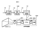
- FIG. 1 is an example of a configuration diagram of a video display apparatus according to the present embodiment.
- This video display device receives a video input signal 10 as an input, for example, an input signal processing unit 11 that converts a compressed video signal into an internal video signal 12 by using a decoder, IP conversion, a scaler, and the like, and a video that receives the internal video signal 12 as an input.
- the optical system apparatus 200 receives a light source 203 for irradiating a light beam for projecting an image on a screen and a display control signal 15 and adjusts the gradation of the light beam from the light source 203 for each pixel to create a projected image. It comprises a panel 202 and a lens 201 for enlarging and projecting a projected image on a screen.
- the lens 201 of the optical system device 200 is not necessary. The user looks directly at the panel 202.
- the first Retinex processing unit 20 and the second Retinex processing unit 22 perform video processing based on the Retinex theory on the internal video signal 12 to obtain the first corrected video signal 21 and the second corrected video signal. 23 is output.
- Retinex theory is a theory showing visual characteristics of the human eye such as color constancy and brightness constancy. According to this theory, it is possible to separate the illumination light component from the image and extract the reflected light component.
- image correction processing based on the Retinex theory removes the influence of illumination light components that cause it to be difficult to see subjects such as people in a dark room or under bright backlight, and extracts reflected light components. By doing so, an image with high visibility can be obtained. For this reason, the natural dynamic range that humans see and feel can be suitably compressed even with digital gradation.
- C / S Center / Surround
- MSR Multiscale Retinex
- SSR is a model that extracts the luminance component of reflected light for one scale from the video (for example, see Reference 2 below), and extends SSR to extract the luminance component of reflected light for a plurality of scales from the video.
- a model (for example, see Reference 3 below) is an MSR.
- the first Retinex processing unit 20 uses the McCann99 model having excellent illumination light estimation performance
- the second Retinex processing unit 22 uses an MSR model having excellent contrast correction performance.
- the feature analysis unit 24 analyzes the characteristics of the internal video signal 12 and outputs a first video synthesis control signal 29 and a second video synthesis control signal 25 to the video synthesis unit 26.
- the video synthesis unit 26 synthesizes the corrected video signal 21 and the corrected video signal 23 based on the first video synthesis control signal 29 and the second video synthesis control signal 25 and outputs the corrected video signal 13.
- FIG. 3 shows an example of the configuration of the video composition unit 26.
- the corrected video signal 21 is multiplied by ⁇ by the gain control unit 27, and the corrected video signal 23 is multiplied by (1 ⁇ ) by the gain control unit 28, added by the adding unit 30, and then ⁇ by the gain control unit 31.
- the corrected video signal 13 is obtained by being multiplied.
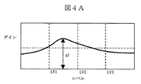
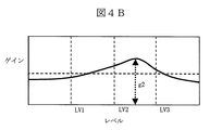
- the horizontal axis represents the luminance level and the vertical axis represents the gain, and each shows an example of the gain characteristic with respect to the luminance level of the first Retinex processing unit 20 and the second Retinex processing unit 22, respectively.
- the McRenn 99 model is used for the first Retinex processing unit 20 and the MSR model is used for the second Retinex processing unit 22 is shown.
- the first Retinex processing unit 20 based on the McCann99 model has a gain peak g1 between the luminance levels LV1 and LV2.
- the second Retinex processing unit 22 using the MSR model has a gain peak g2 between LV2 and LV3.
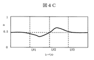
- FIG. 4C shows the first output from the characteristic analysis unit 24 shown in FIG. 2 when the characteristics of the first Retinex processing unit 20 and the second Retinex processing unit 22 are the same as those in FIGS. 4A and 4A described above. It is a figure which shows an example of the synthetic
- the configuration control value is set such that the composite control value ⁇ is decreased at a luminance level where the gain of the first Retinex processing unit 20 is higher than the gain of the second Retinex processing unit 22, and conversely, When the gain of one Retinex processing unit 20 is lower than the gain of the second Retinex processing unit 22, the synthesis control value ⁇ is controlled to be larger.
- the input / output characteristics of the composite output video of the first Retinex processor 20 and the second Retinex processor 22 output from the adder 30 are set to linear characteristics.
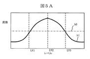
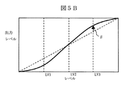
- FIG. 5A and 5B show an example of the control of the second video composition control signal 25 output from the feature analysis unit 24.
- the horizontal axis represents the luminance level of the video
- the vertical axis represents the number of pixels in one screen
- the distribution of each luminance level is graphed as a histogram.
- the histogram h1 indicates that the distribution in the range from the luminance levels LV1 to LV3 is greater than the distribution of the luminance levels below LV1 and above LV3.
- a histogram h0 indicated by a one-dot chain line is obtained.
- the horizontal axis represents the luminance level of the input video
- the vertical axis represents the luminance level of the output video.
- the luminance distribution of FIG. 5A described above is the histogram h1
- An example of the video composition control signal 25 is shown. This is an input / output level characteristic controlled by the gain control value ⁇ .
- the luminance distribution in FIG. 5A is a histogram h0
- the characteristic is indicated by a dotted line in FIG. 5B
- the luminance distribution in FIG. 5A is a histogram h1
- the characteristic is indicated by a solid line in FIG. 5B.
- ⁇ is 1 in LV2, but is smaller than 1 in LV1 and larger than 1 in LV3.
- the slope of the input / output characteristic curve in the range from LV1 to LV3 where the luminance distribution is large becomes steep with respect to the slope of the other regions due to the gain control value ⁇ . It is controlled as follows. By obtaining the corrected video signal 13 with such characteristics, more output luminance levels are assigned to an area having a large distribution in the video, so that a video with good visibility can be obtained.
- 5C to 5F are diagrams for explaining an example of control when the luminance distribution is different from that in FIG. 5A.
- FIG. 5C shows an example of a histogram in the case where the luminance distribution of the luminance level below LV2 is higher than the luminance level above LV2.
- An example of the gain control value ⁇ in this case is shown in FIG. 5D.
- the characteristic curve As shown in FIG. 5D, by controlling the slope of the characteristic curve of LV2 or less having a large luminance distribution to be steeper compared to the luminance level of LV2 or more, the characteristic curve is more increased for the luminance band having a large image distribution. Assign an output brightness level. Thereby, an image with good visibility can be obtained.
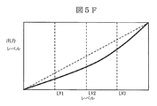
- FIG. 5E shows an example of a histogram when the luminance distribution of the luminance level equal to or higher than LV2 is higher than the luminance level equal to or lower than LV2.
- An example of the gain control value ⁇ in this case is shown in FIG. 5F.
- FIG. 5F by controlling so that the slope of the characteristic curve with LV2 or higher with a large luminance distribution becomes steeper compared with the luminance level with LV2 or lower, the characteristic curve is more increased with respect to the luminance band with a large video distribution. Therefore, it is possible to obtain a video with good visibility.
- the above-described series of control of the video composition unit 26 obtains the advantages of both Retinex processing using the McCann99 model with excellent illumination light estimation performance and Retinex processing using the MSR model with excellent contrast correction performance, and has good visibility. A corrected image is obtained.
- the combination of Retinex models is not limited to the above example, but may be a combination of Retinex demoles of different methods. Further, the present invention is not limited to a combination of two models, and may be a combination of three or more models. In that case, the plurality of Retinex processing units shown in FIG. 2 may be configured to be arranged in parallel so that the corrected video of each Retinex processing unit is synthesized by the synthesis processing unit 26 to obtain the corrected video signal 13.
- Embodiment 2 is an example in which the operation of the image correction unit 100 in the image display apparatus of FIG. Differences from the first embodiment will be described below. Portions that are not particularly described are the same as those in the first embodiment, and thus description thereof is omitted.
- the image correction unit 100 will be described with reference to FIG.
- the first Retinex processing unit 20 and the second Retinex processing unit 22 perform video processing based on Retinex theory of different methods on the internal video signal 12, respectively, so that the corrected video signal 21 and the corrected video signal 23 are processed. Is output.
- the second Retinex processing unit 22 performs Retinex processing with a larger scale than the first Retinex processing unit 20.
- the scale of Retinex processing is the size of the pixel range referred to in Retinex processing.
- the feature analysis unit 24 analyzes the characteristics of the internal video signal 12 and outputs the first video synthesis control signal 29 and the second video synthesis control signal 25 to the video synthesis unit 26.
- the video synthesis unit 26 synthesizes the corrected video signal 21 and the corrected video signal 23 based on the video synthesis control signal 29 and the video synthesis control signal 25 and outputs the corrected video signal 13.
- the second video composition control signal 25 and the gain control value ⁇ of the second embodiment are the same as those of the first embodiment, the description thereof is omitted.
- the gain control value ⁇ by the first video composition control signal 29 in the second embodiment is different from that in the first embodiment. This will be described below.
- FIG. 6 shows an example of output characteristics of the first video composition control signal in the feature analysis unit 24 in the second embodiment.
- the horizontal axis represents the luminance level of the video
- the vertical axis represents the value of the first video composition control signal 29.
- ⁇ is decreased when the luminance level is low
- ⁇ is increased when the luminance level is high.
- the composition ratio can be varied according to the luminance level.
- the corrected video signal 13 obtained by the video synthesizing unit 26 when the luminance level is small, the ratio of the second Retinex processing unit 22 can be increased. Further, when the luminance level is high, the ratio of the first Retinex processing unit 20 can be increased.
- the first retinex processing unit 20 having a small Retinex processing scale includes a large amount of reflected light components having a relatively high frequency component, it is possible to reduce the fineness of the video by increasing the composition ratio in a video region with high luminance. A feeling can be heightened.
- the second retinex processing unit 22 having a large Retinex processing scale includes a large amount of reflected light components having a relatively low frequency component, it is possible to reduce the shadow of the video by increasing the composition ratio in the video region having a low luminance. The visibility of a part can be improved.
- the characteristics shown in FIG. 6 are merely examples, and the maximum value, the minimum value, the gradient of the characteristics, and the like at each luminance level may be determined according to the characteristics of Retinex processing.
- the video composition control signal 29 is generated according to the luminance level of the video, but may be controlled according to the frequency component.
- the control is performed according to the frequency component, for example, when the frequency component for each region of the video signal is high, the ratio of the video signal obtained from the Retinex processing unit having a small scale size in the corrected video signal 13 is increased. However, when the frequency component for each region of the video signal is low, the ratio of the video signal obtained from the Retinex processing unit having a large scale size in the corrected video signal 13 is increased.
- composition control using both the luminance level and the frequency component of the image may be performed. In this case, for example, the above-described control value corresponding to the luminance level and the control value corresponding to the frequency component are added or integrated. Then, the control may be performed with the normalized value.
- both the fineness of the image and the visibility of the shadow portion can be achieved. Is possible.
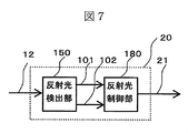
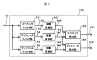
- FIG. 7 is a configuration example of the first Retinex processing unit 20 and detects two reflected light components 101 and 102 by performing video processing based on Retinex theory using the internal video signal 12 as an input signal.
- a reflected light detection unit 150 and a reflected light control unit 180 that receives the two reflected light components detected, adjusts the reflected light, and then recombines them to output the corrected video signal 13.
- the reflection of light is, for example, light that is specularly reflected like a mirror on a smooth surface (hereinafter referred to as specular), or light that is diffusely reflected by fine irregularities on a rough surface (hereinafter referred to as diffuse).
- specular specular
- diffuse specular
- ambient light ambient light that is scattered light by repeatedly reflecting the surrounding environment.
- the material can be expressed by how light is reflected.
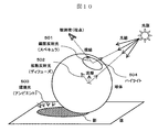
- FIG. 10 is a diagram for explaining an example of the Phong reflection model.
- the figure is composed of a light source, a light beam extending from the light source, a sphere on which the light beam reaches, a floor on which the sphere is placed, and an observer who observes this situation. Observation is performed at the position of the viewpoint, and observation equipment such as a camera or the like may be used, whether it is actually observed with the eyes.
- specular is light 501 in which light rays are reflected on the surface of the sphere in the line-of-sight direction. This is because the light source is reflected on the surface of the sphere, and the circular highlight 504 in the figure is the specular range.
- specular in the case of a plastic sphere, a small circular highlight with high brightness is produced.
- the radius of highlights of rubber-like spheres is wider than that of plastics, but the brightness is low.
- the specular follows the power of the line of sight and the cosine of the reflected light.
- the diffuse is light that diffuses and reflects light 502 having a light beam hitting the sphere surface. Since the brightness of the diffuse is determined by the direction of the light beam and the surface of the sphere, that is, the cosine of the light beam and the normal line, the portion of the sphere surface that is directly exposed to light is the range of the diffuse.
- the ambient light is light 503 that has entered the shadowed portion. This is because the reflected light is reflected several times in the surroundings and the scattered light remains averaged throughout the environment, so that there is a certain brightness even in the shadow portion where the direct light does not reach. Light is diffusely reflected as a shadow, and the brightness is determined by the direction of the ray and the surface of the sphere, the cosine of the ray vector, that is, the normal line.
- the reflected light in the reflected light detection unit is composed of ambient, diffuse, and specular
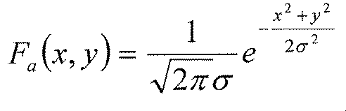
- the ambient in the image follows a wide scale Gaussian
- the diffuse follows the luminance distribution due to the cosine
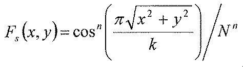
- the specular follows a luminance distribution by the cosine power.
- the ambient filter is Fa (x, y)
- the diffuse filter is Fd (x, y)
- the specular filter is Fs (x, y)
- each filter is represented by the following equation.
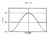
- FIG. 11A, FIG. 11B, and FIG. 11C are diagrams for explaining the distribution of ambient, diffuse, and specular with the vertical axis representing luminance level and the horizontal axis representing one-dimensional position coordinates.
- the levels of the diffuse and specular distributions are sharply lowered compared to the ambient Gaussian distribution.
- the video Ia by the ambient filter is almost only the ambient component in order to average the whole.
- the specular components are averaged by the filter, and are almost only the ambient component and the diffuse component. Since the image Is by the specular filter is hardly averaged, all of the ambient component, the diffuse component, and the specular component remain. This is shown in Equation 5.
- Equation 6 When the reflection component in the logarithmic space is obtained in the same manner as MSR, Equation 6 is obtained.
- Speculars such as mirrors and metals are considered to be total reflection, so the cosine power is infinite.
- Formula 7 may be used as the specular reflection component.
- Equation 8 is obtained.
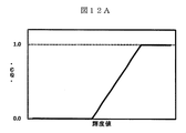
- a gain of a high luminance region as shown in FIG. 12A is added to the specular Rspecular of Equation 6, and a gain of a middle and low luminance region as shown in FIG. 12B is added to the diffuser Rdiffuse. May be added.
- the input / output curve in FIG. 12A is g (I)
- the gain is 0 when the input luminance I is low, the gain gradually increases from medium luminance, and the gain is 1 when the luminance increases.
- the input / output curve of FIG. 12B is 1-g (I), the gain is 1 when the luminance is low, the gain gradually decreases from the middle luminance, and the gain becomes 0 at the high luminance.
- Equation 6 becomes a homomorphic filter when a gain and an exponential function are added after weighted averaging.
- the logarithmic function and the exponential function may be approximated by, for example, a function using a power and its inverse function.
- the function f is expressed by Equation 9.
- FIG. 8 is a diagram for explaining processing of the reflected light detection unit according to the third embodiment.
- the reflected light detection unit 150 includes a specular filter unit 151, a diffuse filter unit 153, an ambient filter unit 155, function conversion units 157, 159, 161, a specular detection unit 163, and a diffuse detection unit 164.
- the function conversion unit may be a logarithmic function or may be approximated by a power function.
- FIG. 9A is a diagram illustrating processing of the reflected light control unit according to the first embodiment.
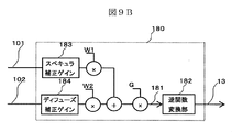
- the reflected light control unit 180 may be configured by a weighted average based on the weights W1 and W2, or may be configured by a weighted average based on the weights W1 and W2, a gain G, and an inverse function conversion unit 182.
- the inverse function conversion unit is an inverse function of the function used in the function conversion unit.
- a specular correction gain 183 having a high gain in the high luminance region of FIG. 12A
- a diffuse correction gain 184 having a high gain in the middle / low luminance region of FIG. 12B are added to the configuration of FIG. 9A. Also good.
- the first corrected video signal 21 having a high quality in consideration of the material of the object in the video can be obtained from the first Retinex processing unit 20.
- the second Retinex processing unit 22 performs video correction using the MSR model.
- processing is performed in which the scale size is larger than that of the first Retinex processing unit 20 described above.
- the first corrected video signal 21 becomes a video signal in consideration of the properties of the object
- the second corrected video signal 23 is a video that has been subjected to contrast correction in a relatively large area of the video. Signal.
- These corrected video signals are synthesized in the same manner as the operation of the video synthesis unit 26 described in the second embodiment.
- the ratio of the second corrected video signal can be increased in the region where the video brightness level is low, so that the contrast improvement effect can be increased, and in the region where the video brightness level is high, the video correction signal considering the nature of the object can be increased. Since the ratio can be increased, an image with good visibility can be obtained as the corrected image signal 13 over the entire band of the luminance level of the image.
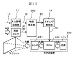
- FIG. 13 is an example of a configuration diagram of the video display device of the present embodiment.
- This video display apparatus receives a video input signal 10 as an input, for example, a compressed video signal decoder, an IP converter, a scaler, etc.
- the illuminance sensor 31 that outputs the illuminance level signal 32
- the video correction unit 300 that receives the internal video signal 12 and the illuminance level signal 32, and the corrected video signal 33 as inputs.
- the timing control unit 14 generates a display control signal 15 based on a vertical synchronization signal, and an optical system device 200 that displays an image.
- FIG. 14 shows a configuration example of the video correction unit 300.
- the video synthesis unit 261 adaptively converts the first corrected video signal 21 and the second corrected video signal 23 by the first video synthesis control signal 29, the second video synthesis control signal 25, and the illuminance level signal 32. Combined and output as a corrected video signal 13.
- FIG. 15 shows an example of the configuration of the video composition unit 261.
- the first video synthesis control signal 29 and the second video synthesis control signal 25 are adjusted by the illumination level signal 32 in the illumination gain adjustment unit 262. Next, they are output as a second illuminance correction signal 251 and a first illuminance correction signal 291, respectively, and applied to the gain control units 27, 28 and 31 as shown in FIG. 15. Thereby, the composite characteristic of the corrected video signal 13 is determined.
- the first video composition control signal 29 is corrected in accordance with the illuminance level signal 32 so that, for example, when the illuminance is high, the composition ratio of the Retinex processing unit having a small scale size is increased.
- the first illuminance correction signal 291 is output. That is, in the configuration example described in the second embodiment, an offset may be added in the direction in which the ⁇ value shown in FIG. 6 increases.
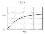
- the second video composition control signal 25 takes, for example, a product with a gain control signal shown in FIG. 16 in accordance with the magnitude of the illuminance level signal 32 to obtain a second illuminance correction signal 251.
- the second video synthesis correction signal 25 may be corrected so that an offset according to the illuminance level signal 32 is added. That is, it is only necessary to control to increase the correction amount in a bright environment according to the illuminance level.
- the visibility of an image can be improved even in a bright environment by controlling the image processing in consideration of the influence of external light.
- FIG. 17 shows an example of the configuration of this embodiment, and a user setting unit 400 is provided.
- the user setting unit 400 inputs an operation signal 401 from a user via an operation of an operation button on the remote controller or the apparatus main body, and outputs an operation command signal to the video correction unit 100 in accordance with the operation signal, so that the video display device It is configured so that the presence / absence of correction and the amount of correction in video processing can be set. Thereby, the setting which switches the image
- the user setting unit 400 is provided in the configuration example of the video display device of FIG. 1, but the configuration is not limited thereto, and the configuration of the video display device having the illuminance sensor illustrated in FIG. 13.
- the user setting unit 400 may be provided. That is, this embodiment may be applied to any of the above-described embodiments.
- FIG. 18 illustrates an example of setting items that can be set in the user setting unit of the present embodiment, using a setting menu screen 1800 displayed by the video display device.
- the setting menu screen 1800 is generated by a menu screen signal generation unit (not shown) of the video display device, and is output instead of the corrected video signal 13. Alternatively, the setting menu screen 1800 is output by being superimposed on the corrected video signal 13.
- the item of “Retinex method selection” 1810 in the example of the setting menu screen 1800 will be described. Based on the item “Retinex method selection” 1810, it is possible to select whether or not to use the retinex processing of both the first retinex processing unit 20 and the second retinex processing unit 22 described in each embodiment. The selection is performed by moving the cursor 1811 via the operation of the operation buttons on the remote controller or the apparatus main body. A selection item and processing in that case will be described. For example, when the selection item “Retinex1 only” is selected, only the processing of the first Retinex processing unit 20 is applied to the processing of the video correction unit, and the processing of the second Retinex processing unit 22 is video correction. Does not apply to part processing.
- the synthesis control value ⁇ may be set to 1, and the operation of the second Retinex processing unit 22 may be turned off.
- the selection item “Retinex2 only” is selected, conversely, only the processing of the second Retinex processing unit 22 is applied to the processing of the video correction unit, and the first Retinex processing unit 20 The processing is not applied to the processing of the video correction unit.
- the synthesis control value ⁇ may be set to 0, and the operation of the first Retinex processing unit 20 may be turned off.
- the selection item “Combining Retinex1 and 2” is selected, the processing of the first Retinex processing unit 20 and the processing of the second Retinex processing unit 22 are combined as described in the above embodiment. And output.
- the selection item “Combining Retinex1 and 2” and the selection item “Retinex OFF” are two. You may just present one. Also, three items may be presented: a selection item “Combining Retinex1 and 2”, a selection item “Retinex1 only”, and a selection item “Retinex OFF”. That is, at least two items of the exemplified options may be presented.
- the intensity of each Retinex process can be set. Specifically, the slide bars 1821 and 1822 are moved via the operation of the operation buttons on the remote controller or the apparatus main body, and the strength of each Retinex process is set.
- the process in that case can be realized, for example, by adding an offset corresponding to the strength to the gain of each Retinex process shown in FIGS. 4A and 4B. For example, when the strength is strong, a plus-direction offset is added to the gain of FIGS. 4A and 4B, and when the strength is weak, a minus-direction offset is added.
- the processing for adding the offset the processing for adding the offset is inserted into the first Retinex processing unit 20 and the second Retinex processing unit 22 or to the corrected video signal 21 and the corrected video signal 23. This can be achieved.
- the item “Retinex intensity setting” 1820 may be configured to switch between an active state and an inactive state according to the selection state of the item “Retinex method selection” 1810.
- the slide bar for the processing that is OFF in the item “Retinex method selection” 1810 may be in an inactive state.
- composition setting 1830 in the example of the setting menu screen 1800 will be described.
- the composition ratio of each Retinex process can be set. This is achieved by controlling the value of ⁇ described in the above embodiments. Specifically, first, the user moves the cursor 1831 via an operation of an operation button on the remote controller or the apparatus main body, and can select either “Variable” or “Fixed”. When “Variable” is selected, the composition control value ⁇ is made variable according to the input video signal as described in the above embodiments. When “Fixed” is selected, the composition control value ⁇ is not changed with respect to the input video signal, but is fixed in a state set by the user.
- the user adjusts the slide bar 1832 through the operation of an operation button on the remote controller or the apparatus main body, and is set in a state of being fixed to the composite control value ⁇ corresponding to the position.
- ⁇ is increased as the bar moves to the left, and the processing of the first Retinex processing unit 20 is preferentially combined.
- ⁇ becomes smaller, and the processing of the second Retinex processing unit 22 is preferentially combined.
- the “composite setting” 1830 item may be configured to switch between an active state and an inactive state according to the selection state of the “Retinex method selection” 1810 item. That is, when the selection item “Combining Retinex1 and 2” is not selected, the entire “Combination setting” 1830 item may be inactive.
- This item can set the magnitude of the processing effect of the gain control unit 31 in FIG. Specifically, the magnitude of the change amount of the gain control value ⁇ is changed according to the movement of the slide bar 1840. In any of the characteristics of FIG. 5B, FIG. 5D, and FIG. 5F, if the amplitude of the change amount of the gain control value ⁇ is increased, the visibility improving process is strengthened.
- This item is a menu item used when the user setting unit 400 is provided in the configuration example of the video display device having the illuminance sensor illustrated in FIG.
- the user can move the cursor 1851 through the operation of the operation button on the remote controller or the apparatus main body, and select either “ON” or “OFF”.
- the gain control value of FIG. 16 described in the fourth embodiment is fixed to 1.
- the video correction processing in each embodiment of the present invention is performed according to the user's preference, the purpose of use of the video display device, or the usage environment. It is possible for the user to adjust according to the above. As a result, a more convenient video display device can be provided.
- an image display device that performs image correction by decomposing an image for each light reflection property will be described with reference to a projector configuration.
- a front projector will be described, but the form may be a rear projection television.
- a display device using a direct-view flat display such as a liquid crystal display, a plasma display, or an organic EL display may be used without enlarging the panel. This is the same in any of the following embodiments.
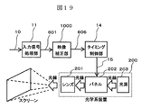
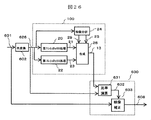
- FIG. 19 is an example of a configuration diagram of the video display device of the present embodiment.
- This video display apparatus receives a video input signal 10 as an input, for example, an input signal processing unit 11 that converts a compressed video signal into an internal video signal 601 by a decoder, IP conversion, a scaler, and the like, and a video that receives the internal video signal 601 as an input.
- the video correction unit 1000 may be simply expressed as a video processing unit.
- the optical system apparatus 200 receives a light source 203 for irradiating a light beam for projecting an image on a screen and a display control signal 15 and adjusts the gradation of the light beam from the light source 203 for each pixel to create a projected image. It comprises a panel 202 and a lens 201 for enlarging and projecting a projected image on a screen.
- the lens 201 of the optical system device 200 is not necessary. The user looks directly at the panel 202.
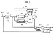
- the color conversion unit 602 converts the internal video signal 601 input in RGB format into, for example, YUV format, and outputs the internal video signal 625.
- the format of the internal video signal 625 is not limited to the YUV format as long as it can be converted into the luminance signal Y and the color signal.
- the first Retinex processing unit 20 and the second Retinex processing unit 22 perform video processing based on Retinex theory on the luminance signal Y of the internal video signal 625, and perform the first corrected video signal 21 and the second corrected video signal 21.
- the corrected video signal 23 is output.
- the feature analysis unit 24 analyzes the characteristics of the internal video signal 625 and outputs the first video synthesis control signal 29 and the second video synthesis control signal 25 to the video synthesis unit 26.
- the video synthesis unit 26 synthesizes the corrected video signal 21 and the corrected video signal 23 based on the first video synthesis control signal 29 and the second video synthesis control signal 25 and outputs the corrected video signal 13.
- the operation of the video composition unit 26 is the same as the example described in the first embodiment, and a detailed description thereof is omitted.
- the color conversion unit 603 uses the luminance signal Y of the corrected video signal 13 and the color signal UV of the internal video signal 625, converts it into a corrected video signal 604 in the RGB format, and outputs it. At this time, there may be a timing difference between the corrected video signal 13 and the internal video signal 625 due to the processing configuration of each Retinex processing unit and the video synthesis unit 26 described above. Is converted into a corrected video signal 604.
- the output video generation unit 605 corrects the internal video signal 601 based on the ratio of the video signal level between the internal video signal 601 and the corrected video signal 604 and outputs it as a new output video signal 606.
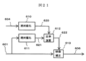
- FIG. 21 shows an example of the configuration of the output video generation unit 605.
- the absolute value converting unit 610 calculates the absolute value of the video level from the RGB components of the corrected video signal 604 and outputs a video level signal 620.
- the absolute value converting unit 611 calculates the absolute value of the video level from the RGB components of the internal video signal 601 and outputs a video level signal 621.
- the arithmetic unit 612 calculates the ratio of the magnitudes of the video level signal 620 and the video level signal 621 described above, and outputs a correction ratio signal 622.
- the video correction unit 613 corrects the internal video signal 601 based on the correction ratio signal 622 and outputs an output video signal 606. Specifically, the correction is performed by multiplying the RGB components of the internal video signal 601
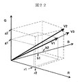
- FIG. 22 An example of this specific correction is shown in FIG. In FIG. 22, the RGB level of the video signal is shown on each RGB axis in the RGB color space.
- the RGB level of the internal video signal 601 described above is (r1, g1, b1)
- the vector V1 has information on the ratio of a plurality of color parameters of the internal video signal 601.
- the level of the corrected video signal 604 is (r2, g2, b2)
- the absolute values of the vectors that is, the lengths of the vectors V1 and V2 are obtained from the respective RGB components and used as the video level signals 620 and 621.
- the arithmetic unit 612 obtains a ratio of magnitude from the absolute value of the video level, and the video correction unit 613 performs multiplication.
- the output video signal 606 obtained in this way is as indicated by the broken line V3 in FIG. That is, the vector is in the same direction as V1, and the ratio of the plurality of color parameters of the internal video signal 601 is maintained, so that it is possible to obtain a video with good visibility while maintaining the hue of the internal video signal 601. It becomes.
- the processing is described as “correcting the internal video signal 601”, but the RGB level vector of the internal video signal 601 and its absolute value, and the RGB level vector of the corrected video signal 604 It can be said that a new output video signal is generated based on the absolute value.
- the internal video signal 601 is corrected using the ratio of the absolute values of the RGB levels of the internal video signal 601 and the corrected video signal 604 has been described.
- the internal video signal 601 can also be corrected using the ratio of the signal (Y).
- FIG. 26 shows an example of the configuration of the video correction unit 1000 in that case.
- the color conversion unit 602 outputs an internal video signal 626 from the RGB format signal of the internal video signal 601. Since the operations of the first Retinex processing unit 20, the second Retinex processing unit 22, the feature analysis unit 24, and the video composition unit 26 are the same as those described above, description thereof will be omitted.
- the computing unit 631 in the output video generation unit 630 obtains a ratio between the level of the corrected luminance signal 13 and the luminance signal level of the internal video signal 626 and outputs a correction ratio signal 632.
- the video correction unit 633 corrects the internal video signal 601 based on the correction ratio signal 632 and outputs an output video signal 608. Specifically, the correction is performed by multiplying the RGB components of the internal video signal 601 by the correction ratio signal 632, respectively. Also in this configuration example, it is possible to obtain a video with good visibility while maintaining the color of the internal video signal 601.
- information on the color of the video signal before video correction by Retinex processing vector information on the color space or information on the ratio of a plurality of color parameters
- Retinex processing A new video signal can be generated on the basis of information on the absolute value of the color space vector before or after video correction according to the above or information on the luminance ratio. Accordingly, it is possible to generate and display a video signal closer to the color balance before the Retinex process while obtaining the effect of improving the visibility by the Retinex process.
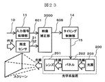
- FIG. 23 is an example of a configuration diagram of the video display device of the present embodiment.
- This video display device receives a video input signal 10 as an input, for example, a compressed video signal decoder, an IP converter, a scaler, etc.
- the illuminance sensor 31 that outputs the illuminance level signal 32
- the video correction unit 3000 that receives the internal video signal 601 and the illuminance level signal 32 as inputs, and the output video signal 608 as an input
- the timing control unit 14 generates a display control signal 15 based on a vertical synchronization signal, and an optical system device 200 that displays an image.
- the video correction unit 3000 may be simply expressed as a video processing unit.
- FIG. 24 shows a configuration example of the video correction unit 3000.
- the output video generation unit 607 adaptively combines the corrected video signal 604 with the internal video signal 601 and the illuminance level signal 32 and outputs the resultant as the output video signal 608. Note that components having the same reference numerals as those in FIG. 20 described in the sixth embodiment have the same functions.
- FIG. 25 shows an example of the configuration of the output video generation unit 607.
- the video correction unit 615 performs correction as follows using the internal video signal 601, the correction ratio signal 622, and the illuminance level signal 32, and outputs an output video signal 608.
- the maximum illuminance in Expression 11 is a preset maximum illuminance level, and the illuminance level signal 32 does not exceed the maximum illuminance level.
- the processing of the video correction unit 615 when the illuminance level is high, the correction amount for the internal video signal 601 can be increased, and when the illuminance level is low, the correction amount can be reduced. This makes it possible to improve the visibility by changing the video correction amount according to the brightness of the place where the video is displayed.For example, in a bright place, increasing the video correction amount can increase the visibility. An improvement effect can be obtained.
- information on the color of the video signal before video correction by Retinex processing vector information on the color space or information on the ratio of a plurality of color parameters
- Retinex processing A new video signal can be generated based on information on the absolute value or luminance ratio of the color space vector before and after video correction, and the visibility improvement effect is adjusted according to the brightness of the place where the video is displayed It becomes possible. Accordingly, it is possible to generate and display a video signal closer to the color balance before the Retinex process, while more suitably obtaining the visibility improvement effect by the Retinex process.
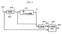
- the video display apparatus of the present embodiment is the same as the video display apparatus of the sixth embodiment of the present invention shown in FIG. 19 in which the internal structure of the video correction unit 1000 is configured as shown in FIG.
- the first Retinex processing unit 20 in FIG. 27 performs the same processing as the first Retinex processing unit 20 described in the third embodiment.
- the Retinex processing is performed using the Phong reflection model that expresses the shadow of the object surface using the properties of the three lights.
- the video signal generation process is performed by the output video generation unit 605.
- the color conversion unit 602 converts the internal video signal 601 input in RGB format into, for example, YUV format, and outputs the internal video signal 625.
- the format of the internal video signal 625 is not limited to the YUV format as long as it can be converted into the luminance signal Y and the color signal.
- the first Retinex processing unit 20 performs video processing based on Retinex theory on the luminance signal Y of the internal video signal 625 and outputs a corrected video signal 21.
- the color conversion unit 603 uses the Y signal of the corrected video signal 21 and the color signal UV of the internal video signal 625 to convert to a corrected video signal 604 in the RGB format and output it. At this time, there may be a video timing difference between the corrected video signal 21 and the internal video signal 625 due to the processing configuration of each Retinex processing unit and the video synthesis unit 26 described above. Is converted into a corrected video signal 604.
- the output video generation unit 605 corrects the internal video signal 601 based on the ratio of the video signal level between the internal video signal 601 and the corrected video signal 604 and outputs it as the output video signal 606.
- This process is the same as in the sixth embodiment, and the ratio of the video level is obtained from the absolute value of the color space vector according to the RGB level of each video signal or the Y signal of each video signal. According to the present embodiment, it is possible to obtain an output video signal 606 having a high quality in consideration of the material of the object while maintaining the color of the object in the input video.
- information on the color of the video signal before video correction by Retinex processing vector information on the color space or information on the ratio of a plurality of color parameters
- Retinex processing A new video signal can be generated based on information on the absolute value of the color space vector before and after video correction or the luminance ratio information. Accordingly, it is possible to generate and display a video signal closer to the color balance before the Retinex process, while more suitably obtaining the visibility improvement effect by the Retinex process. Further, the video display apparatus according to the present embodiment can be realized with a simpler configuration than that of the sixth embodiment.
- the illuminance sensor 31 may be provided in the configuration of the present embodiment in the same manner as in the seventh embodiment, and control by the illuminance level signal 32 may be added.
- the user setting unit 400 similar to that of the fifth embodiment is provided in each configuration of the sixth, seventh, and eighth embodiments, and the setting menu screen 1800 of FIG. 18 is displayed according to the operation signal 401 from the user to display each item. You may comprise so that a user setting is possible.
Landscapes
- Engineering & Computer Science (AREA)
- Multimedia (AREA)
- Signal Processing (AREA)
- Physics & Mathematics (AREA)
- Computer Hardware Design (AREA)
- General Physics & Mathematics (AREA)
- Theoretical Computer Science (AREA)
- Image Processing (AREA)
- Video Image Reproduction Devices For Color Tv Systems (AREA)
- Processing Of Color Television Signals (AREA)
Abstract
Description
〔参考文献1〕野里 良裕,他 「適応的階調補正のハードウェア実現における Retinex理論の比較評価」, 信学技報, SIS2005-16, (2005).
〔参考文献2〕D.J.Jobson and G.A.Woodell, Properties of a Center/Surround Retinex: Part 2.Surround Design,NASA Technical Memorandum,110188,1995.
〔参考文献3〕Zia-ur Rahman, Daniel J. Jobson, and Glenn A. Woodell, ”Multiscale Retinex For Color Image Enhancement”, ICIP ’96
本実施例では、一例として、第1のレティネックス処理部20は、照明光推定性能に優れるMcCann99モデルを用い、第2のレティネックス処理部22は、コントラスト補正性能に優れるMSRモデルを用いることとする。特徴分析部24は、内部映像信号12の特徴を分析し、映像合成部26へ第1の映像合成制御信号29および第2の映像合成制御信号25を出力する。映像合成部26では、第1の映像合成制御信号29および第2の映像合成制御信号25に基づき、補正映像信号21および補正映像信号23を合成して補正映像信号13を出力する。









12 内部映像信号
13 補正映像信号
15 表示制御信号
20 第1のレティネックス処理部
21 第1の補正映像信号
22 第2レティネックス処理部
23 第2の補正映像信号
24 特徴分析部
25 映像合成制御信号
26 映像合成部
27、28、31 利得制御部
29 映像合成制御信号
30 加算器
32 照度レベル信号
33 適応制御による補正映像信号
100 映像補正部
101 スケール1による反射光成分
102 スケール2による反射光成分
120 MSRによる反射光検出部
122 スケール1フィルタによるコンボリューション積の結果
124 スケール2フィルタによるコンボリューション積の結果
126 スケール1によるSSRの結果値
128 スケール2によるSSRの結果値
130 MSRによる反射光制御部
131 各SSRの結果に対する加重平均結果値(ゲイン含む)
152 スペキュラフィルタによるコンボリューション積の結果
154 ディフューズフィルタによるコンボリューション積の結果
156 アンビエントフィルタによるコンボリューション積の結果
158 スペキュラフィルタに対する関数変換の結果
160 ディフューズフィルタに対する関数変換の結果
162 アンビエントフィルタに対する関数変換の結果
181 スペキュラおよびディフューズに対する加重平均結果値(ゲイン含む)
302 エッジ信号
601 内部映像信号
602、603 色変換部
604 補正映像信号
605、607、630 出力映像生成
606、608 出力映像信号
610、611 絶対値化部
612、631 演算器
613、615、633 映像補正部
1000、3000 映像補正部
Claims (10)
- 映像を入力する映像入力部と、
前記映像入力部が入力した入力映像についてレティネックス処理を行い、前記入力映像における色に関する情報と、前記レティネックス処理が施された映像信号における色空間ベクトルの絶対値またはY値の情報とにもとづいて新たな映像信号を生成する映像信号生成を行う映像処理部と、
前記映像処理部で映像処理した映像信号にもとづいて映像を表示する表示部と、
を備えることを特徴とする映像表示装置。 - 請求項1に記載の映像表示装置であって、
前記映像処理部は、前記レティネックス処理には、前記入力映像について第1のレティネックス処理を行う第1のレティネックス処理を行い、前記入力映像について前記第1のレティネックス処理と方式の異なる第2のレティネックス処理を行う第2のレティネックス処理を行い、前記入力映像の特徴に応じて前記第1のレティネックス処理を施した映像と前記第2のレティネックス処理を施した映像とを合成する合成処理が含まれることを特徴とする映像表示装置。 - 請求項1に記載の映像表示装置であって、
前記映像処理部で生成する映像信号は、前記入力映像が有する色空間上のベクトルと同じ方向の色空間上のベクトルまたは前記入力映像が有する色パラメータの比率と同じ比率の色パラメータを有し、前記色空間ベクトルの絶対値またはY値が、前記レティネックス処理が施された映像の信号における色空間ベクトルの絶対値またはY値と同じであることを特徴とする映像表示装置。 - 請求項2に記載の映像表示装置であって、
前記表示部には、設定メニュー画面が表示可能であり、
前記設定メニュー画面では、前記表示部での映像表示状態の切替設定として、
前記第1のレティネックス処理を施した映像と前記第2のレティネックス処理を施した映像とを映像合成して表示する第1の状態、
前記第2のレティネックス処理を施さず、前記第1のレティネックス処理を施した映像を表示する第2の状態、
前記第1のレティネックス処理を施さず、前記第2のレティネックス処理を施した映像を表示する第3の状態、
前記第1のレティネックス処理も前記第2のレティネックス処理も施していない映像を表示する第4の状態、
のうち、少なくとも2つの表示状態を切り替え可能であることを特徴とする映像表示装置。 - 請求項4に記載の映像表示装置であって、
前記設定メニュー画面では、
前記第1のレティネックス処理を施した映像と前記第2のレティネックス処理を施した映像とを映像合成する際の合成比率を変更可能であることを特徴とする映像表示装置。 - 請求項2に記載の映像表示装置であって、
前記第1のレティネックス処理におけるスケールと、前記第2のレティネックス処理におけるスケールが異なることを特徴とする映像表示装置。 - 請求項2に記載の映像表示装置であって、
前記合成処理では、前記入力映像の輝度情報または周波数情報に応じて、前記第1のレティネックス処理を施した映像と前記第2のレティネックス処理を施した映像との合成比率を変更することを特徴とする映像表示装置。 - 請求項6に記載の映像表示装置であって、
前記第1のレティネックス処理におけるスケールが、前記第2のレティネックス処理におけるスケールよりも小さく、
前記合成処理では、
前記入力映像の輝度が比較的高い場合に、前記第1のレティネックス処理を施した映像の合成比率を前記第2のレティネックス処理を施した映像よりも大きくし、
前記入力映像の輝度が比較的低い場合に、前記第1のレティネックス処理を施した映像の合成比率を前記第2のレティネックス処理を施した映像よりも小さくすることを特徴とする映像表示装置。 - 請求項1に記載の映像表示装置であって、
さらに、外光の照度を測る照度センサを備え、
前記照度センサの測定結果に応じて、前記合成処理を変更することを特徴とする映像表示装置。 - 請求項1に記載の映像表示装置であって、
前記第1のレティネックス処理は、入力映像を複数の反射光成分に分離し、分離された前記複数の反射光成分のそれぞれを重み値によって調整し、加重平均し、映像中の反射光の割合を制御する処理であり、
前記第2のレティネックス処理は、前記第1のレティネックス処理よりもスケールの大きなレティネックス処理であることを特徴とする映像表示装置。
Priority Applications (5)
| Application Number | Priority Date | Filing Date | Title |
|---|---|---|---|
| CN201380081652.6A CN105830438B (zh) | 2013-12-25 | 2013-12-25 | 影像显示装置 |
| PCT/JP2013/084655 WO2015097780A1 (ja) | 2013-12-25 | 2013-12-25 | 映像表示装置 |
| US15/101,083 US10013905B2 (en) | 2013-12-25 | 2013-12-25 | Image display device using combined Retinex processing |
| JP2015554359A JP6335924B2 (ja) | 2013-12-25 | 2013-12-25 | 映像表示装置 |
| US15/995,263 US10134323B2 (en) | 2013-12-25 | 2018-06-01 | Image display device |
Applications Claiming Priority (1)
| Application Number | Priority Date | Filing Date | Title |
|---|---|---|---|
| PCT/JP2013/084655 WO2015097780A1 (ja) | 2013-12-25 | 2013-12-25 | 映像表示装置 |
Related Child Applications (2)
| Application Number | Title | Priority Date | Filing Date |
|---|---|---|---|
| US15/101,083 A-371-Of-International US10013905B2 (en) | 2013-12-25 | 2013-12-25 | Image display device using combined Retinex processing |
| US15/995,263 Continuation US10134323B2 (en) | 2013-12-25 | 2018-06-01 | Image display device |
Publications (1)
| Publication Number | Publication Date |
|---|---|
| WO2015097780A1 true WO2015097780A1 (ja) | 2015-07-02 |
Family
ID=53477722
Family Applications (1)
| Application Number | Title | Priority Date | Filing Date |
|---|---|---|---|
| PCT/JP2013/084655 Ceased WO2015097780A1 (ja) | 2013-12-25 | 2013-12-25 | 映像表示装置 |
Country Status (4)
| Country | Link |
|---|---|
| US (2) | US10013905B2 (ja) |
| JP (1) | JP6335924B2 (ja) |
| CN (1) | CN105830438B (ja) |
| WO (1) | WO2015097780A1 (ja) |
Cited By (2)
| Publication number | Priority date | Publication date | Assignee | Title |
|---|---|---|---|---|
| WO2018167898A1 (ja) * | 2017-03-15 | 2018-09-20 | マクセル株式会社 | 映像表示装置 |
| JPWO2021070342A1 (ja) * | 2019-10-10 | 2021-04-15 |
Families Citing this family (4)
| Publication number | Priority date | Publication date | Assignee | Title |
|---|---|---|---|---|
| CN105830438B (zh) * | 2013-12-25 | 2018-04-06 | 麦克赛尔株式会社 | 影像显示装置 |
| EP3057067B1 (en) * | 2015-02-16 | 2017-08-23 | Thomson Licensing | Device and method for estimating a glossy part of radiation |
| KR20220077730A (ko) * | 2020-12-02 | 2022-06-09 | 삼성전자주식회사 | 이미지 처리 방법 및 장치 |
| CN119379656A (zh) * | 2024-10-31 | 2025-01-28 | 中国民用航空飞行学院 | 一种焊接电路板的图像法智能检测方法及系统 |
Citations (3)
| Publication number | Priority date | Publication date | Assignee | Title |
|---|---|---|---|---|
| JP2004038842A (ja) * | 2002-07-08 | 2004-02-05 | Matsushita Electric Ind Co Ltd | 画像処理装置及び画像処理方法 |
| JP2005176171A (ja) * | 2003-12-15 | 2005-06-30 | Matsushita Electric Ind Co Ltd | 輝度補正装置 |
| JP2012085182A (ja) * | 2010-10-13 | 2012-04-26 | Olympus Corp | 画像処理装置、画像処理プログラム、及び、画像処理方法 |
Family Cites Families (3)
| Publication number | Priority date | Publication date | Assignee | Title |
|---|---|---|---|---|
| WO2003069557A1 (en) | 2002-02-12 | 2003-08-21 | Matsushita Electric Industrial Co., Ltd. | Image processing device and image processing method |
| JP4345366B2 (ja) | 2003-06-12 | 2009-10-14 | コニカミノルタホールディングス株式会社 | 画像処理プログラムおよび画像処理装置 |
| CN105830438B (zh) * | 2013-12-25 | 2018-04-06 | 麦克赛尔株式会社 | 影像显示装置 |
-
2013
- 2013-12-25 CN CN201380081652.6A patent/CN105830438B/zh active Active
- 2013-12-25 JP JP2015554359A patent/JP6335924B2/ja active Active
- 2013-12-25 US US15/101,083 patent/US10013905B2/en active Active
- 2013-12-25 WO PCT/JP2013/084655 patent/WO2015097780A1/ja not_active Ceased
-
2018
- 2018-06-01 US US15/995,263 patent/US10134323B2/en active Active
Patent Citations (3)
| Publication number | Priority date | Publication date | Assignee | Title |
|---|---|---|---|---|
| JP2004038842A (ja) * | 2002-07-08 | 2004-02-05 | Matsushita Electric Ind Co Ltd | 画像処理装置及び画像処理方法 |
| JP2005176171A (ja) * | 2003-12-15 | 2005-06-30 | Matsushita Electric Ind Co Ltd | 輝度補正装置 |
| JP2012085182A (ja) * | 2010-10-13 | 2012-04-26 | Olympus Corp | 画像処理装置、画像処理プログラム、及び、画像処理方法 |
Cited By (6)
| Publication number | Priority date | Publication date | Assignee | Title |
|---|---|---|---|---|
| WO2018167898A1 (ja) * | 2017-03-15 | 2018-09-20 | マクセル株式会社 | 映像表示装置 |
| JPWO2018167898A1 (ja) * | 2017-03-15 | 2019-12-12 | マクセル株式会社 | 映像表示装置 |
| JPWO2021070342A1 (ja) * | 2019-10-10 | 2021-04-15 | ||
| WO2021070342A1 (ja) * | 2019-10-10 | 2021-04-15 | マクセル株式会社 | 映像表示装置およびプロジェクタ |
| JP7344975B2 (ja) | 2019-10-10 | 2023-09-14 | マクセル株式会社 | 映像表示装置およびプロジェクタ |
| US12081916B2 (en) | 2019-10-10 | 2024-09-03 | Maxell, Ltd. | Video display device and projector |
Also Published As
| Publication number | Publication date |
|---|---|
| JP6335924B2 (ja) | 2018-05-30 |
| CN105830438A (zh) | 2016-08-03 |
| US20180286301A1 (en) | 2018-10-04 |
| US10013905B2 (en) | 2018-07-03 |
| US10134323B2 (en) | 2018-11-20 |
| CN105830438B (zh) | 2018-04-06 |
| JPWO2015097780A1 (ja) | 2017-03-23 |
| US20160307489A1 (en) | 2016-10-20 |
Similar Documents
| Publication | Publication Date | Title |
|---|---|---|
| JP5247910B1 (ja) | 画像表示装置またはその方法 | |
| JP6046238B2 (ja) | 映像表示装置 | |
| JP6030396B2 (ja) | 映像処理装置 | |
| US10134323B2 (en) | Image display device | |
| JP6550138B2 (ja) | 映像処理装置 | |
| KR101648762B1 (ko) | 입력 영상의 동적 범위를 변환하는 방법 및 장치 | |
| JP6738480B2 (ja) | 映像表示装置 | |
| US20240397024A1 (en) | Video display device and projector | |
| KR101872015B1 (ko) | 적외선 영상 생성장치 및 방법 | |
| JP2021087083A (ja) | 画像処理装置、画像処理方法及びプログラム | |
| JP2015138108A (ja) | 表示装置及び画質調整装置 |
Legal Events
| Date | Code | Title | Description |
|---|---|---|---|
| 121 | Ep: the epo has been informed by wipo that ep was designated in this application |
Ref document number: 13900059 Country of ref document: EP Kind code of ref document: A1 |
|
| ENP | Entry into the national phase |
Ref document number: 2015554359 Country of ref document: JP Kind code of ref document: A |
|
| WWE | Wipo information: entry into national phase |
Ref document number: 15101083 Country of ref document: US |
|
| NENP | Non-entry into the national phase |
Ref country code: DE |
|
| 122 | Ep: pct application non-entry in european phase |
Ref document number: 13900059 Country of ref document: EP Kind code of ref document: A1 |