WO2015096869A1 - Piston head for use in a reciprocating compressor and method of producing the same - Google Patents
Piston head for use in a reciprocating compressor and method of producing the same Download PDFInfo
- Publication number
- WO2015096869A1 WO2015096869A1 PCT/EP2013/078009 EP2013078009W WO2015096869A1 WO 2015096869 A1 WO2015096869 A1 WO 2015096869A1 EP 2013078009 W EP2013078009 W EP 2013078009W WO 2015096869 A1 WO2015096869 A1 WO 2015096869A1
- Authority
- WO
- WIPO (PCT)
- Prior art keywords
- base section
- rim flange
- piston head
- annular rim
- projection portion
- Prior art date
Links
Images


Classifications
-
- F—MECHANICAL ENGINEERING; LIGHTING; HEATING; WEAPONS; BLASTING
- F04—POSITIVE - DISPLACEMENT MACHINES FOR LIQUIDS; PUMPS FOR LIQUIDS OR ELASTIC FLUIDS
- F04B—POSITIVE-DISPLACEMENT MACHINES FOR LIQUIDS; PUMPS
- F04B39/00—Component parts, details, or accessories, of pumps or pumping systems specially adapted for elastic fluids, not otherwise provided for in, or of interest apart from, groups F04B25/00 - F04B37/00
- F04B39/0005—Component parts, details, or accessories, of pumps or pumping systems specially adapted for elastic fluids, not otherwise provided for in, or of interest apart from, groups F04B25/00 - F04B37/00 adaptations of pistons
-
- F—MECHANICAL ENGINEERING; LIGHTING; HEATING; WEAPONS; BLASTING
- F04—POSITIVE - DISPLACEMENT MACHINES FOR LIQUIDS; PUMPS FOR LIQUIDS OR ELASTIC FLUIDS
- F04B—POSITIVE-DISPLACEMENT MACHINES FOR LIQUIDS; PUMPS
- F04B27/00—Multi-cylinder pumps specially adapted for elastic fluids and characterised by number or arrangement of cylinders
- F04B27/08—Multi-cylinder pumps specially adapted for elastic fluids and characterised by number or arrangement of cylinders having cylinders coaxial with, or parallel or inclined to, main shaft axis
- F04B27/0873—Component parts, e.g. sealings; Manufacturing or assembly thereof
- F04B27/0878—Pistons
-
- F—MECHANICAL ENGINEERING; LIGHTING; HEATING; WEAPONS; BLASTING
- F04—POSITIVE - DISPLACEMENT MACHINES FOR LIQUIDS; PUMPS FOR LIQUIDS OR ELASTIC FLUIDS
- F04B—POSITIVE-DISPLACEMENT MACHINES FOR LIQUIDS; PUMPS
- F04B39/00—Component parts, details, or accessories, of pumps or pumping systems specially adapted for elastic fluids, not otherwise provided for in, or of interest apart from, groups F04B25/00 - F04B37/00
- F04B39/12—Casings; Cylinders; Cylinder heads; Fluid connections
- F04B39/125—Cylinder heads
-
- F—MECHANICAL ENGINEERING; LIGHTING; HEATING; WEAPONS; BLASTING
- F04—POSITIVE - DISPLACEMENT MACHINES FOR LIQUIDS; PUMPS FOR LIQUIDS OR ELASTIC FLUIDS
- F04B—POSITIVE-DISPLACEMENT MACHINES FOR LIQUIDS; PUMPS
- F04B39/00—Component parts, details, or accessories, of pumps or pumping systems specially adapted for elastic fluids, not otherwise provided for in, or of interest apart from, groups F04B25/00 - F04B37/00
- F04B39/14—Provisions for readily assembling or disassembling
Definitions
- the present invention relates to a piston head for use in a reciprocating compressor and a method of producing a piston head.
- a domestic refrigerator is typically provided with a reciprocating compressor for circulating a refrigerant of a refrigeration circuit.
- the conventional reciprocating compressor conveys the refrigerant from an evaporator side to a condenser side.
- the conventional reciprocating compressor comprises a cylinder block which has a chamber in which the refrigerant is cyclically compressed; a piston mechanism for compressing the refrigerant in the chamber; and an electrical motor for driving the piston mechanism.
- the cylinder block further includes an intake chamber and a discharge chamber.
- the intake chamber is on a downstream side of the evaporator.
- the discharge chamber is on an upstream side of the condenser.
- the intake chamber and the discharge chamber are usually formed within the cylinder head.
- a valve plate is interposed between the cylinder block and the cylinder head.
- the compression chamber is selectively brought into fluid communication with the intake chamber and the discharge chamber.
- the valve plate generally comprises an intake port and a discharge port.
- the intake port fluidly connects the intake chamber with the compression chamber upon suction of the piston mechanism.
- the discharge port fluidly connects the compression chamber with the discharge chamber upon compression of the piston mechanism.
- the piston mechanism includes a piston head arranged to reciprocate within the chamber, a piston rod pivotably coupled to the piston head and a crank shaft pivotably coupled to the piston rod.
- the crankshaft has a counterweight for smoothing the operation of the piston mechanism.
- the crankshaft is rotatably supported by the cylinder block.
- the electrical motor includes: a stator and a rotor which are typically configured as an asynchronous motor or a brushless direct current motor. The rotor is fixed to the crank shaft of the piston mechanism.
- a problem with the conventional reciprocating compressor is that as the crankshaft maximally pushes the piston head into the chamber, a small fraction of the refrigerant in the vicinity of the discharge port remains undischarged due to a groove shape of the discharge port.
- the piston head is usually provided with a projection portion which loosely fits into the groove as the crankshaft is moved to its dead point.
- JP 57-056133 discloses a method for manufacturing a cylindrical piston head with a projection portion.
- This piston head has a cylindrical body which includes: an upper base section, a cylindrical lateral section and a lower base section. According to this method, the piston head is produced through cold forging without any after-treatment such as grinding or the like.
- the grinding process is indispensable for obtaining fine finishes and accurate dimensions.
- Several grinding techniques are known.
- An efficient way of grinding the piston head is to use a centerless grinding technique since a plurality of the piston heads can be stacked upon each other and commonly grinded. Thereby, a capacity of the grinding machine can be fully utilized the manufacturing cost can be reduced.
- a drawback of the above prior art piston head is that it cannot be stacked upon another one unless e.g., a suitable dummy is arranged in between two neighboring piston heads.
- a suitable dummy is arranged in between two neighboring piston heads.
- the use of dummies reduces the grinding capacity and increases the costs.
- a further drawback of the aforementioned piston head is that it easily interferes with the counterweight of the crankshaft due to a shape of its skirt unless it is arranged sufficiently away from the counterweight. However such an arrangement reduces the compression capacity of the chamber.
- An objective of the present invention is to provide a method of producing a piston head which overcomes the aforementioned problems of the prior art and which enables a highly accurate and a cost effective production of a piston head.
- annular rim flange is formed on the lower base section of the cylindrical body.
- the annular rim flange has a height which is equal to or higher than a height of the projection portion.
- the projection portion is formed on the upper base section directly above a region of the lower base section, which is enclosed by an inner side of the annular rim flange. The upper surface of the annular rim flange and the surface of the upper base section except for the projection portion are both leveled.
- one or more than one cut out is formed in the annular rim flange.
- the cut outs prevent an interference between the counterweight of the crankshaft and the annular rim flange.
- the piston head is integrally formed through a die forging process. In an alternative embodiment, the piston head is integrally formed through a cast molding process.
- cut outs are formed through a machining process which is performed subsequent to said die forging process or said cast molding process.
- annular rim flange and the cut outs are both formed through a machining process subsequent to said die forging process or said cast molding process.
- the method further comprises a step of centerless grinding in which a plurality of cylindrical bodies are stacked on top of each other and their cylindrical lateral sections are commonly grinded. In this embodiment, no dummies are placed in-between the plurality of piston heads.
- the piston heads can be directly stacked on top of each other to obtain a stack of a plurality of piston heads.
- each projection portion is stowed away in the gap enclosed by the annular rim flange of an adjacent piston head and each upper surface of the annular rim flange uniformly abuts against the surface of the upper base section of the other adjacent piston head.
- Figure 1a – is a schematic perspective rear view of a piston head according to an embodiment of the present invention, prior to forming of a cut out in a rim flange thereof through a machining process;
- Figure 1b – is a schematic perspective front view of the piston head shown in Fig. 1a;
- Figure 2a – is a schematic perspective rear view of the piston head according to an embodiment of the present invention with a pair of cut outs formed in the rim flange;
- Figure 2b – is a schematic perspective front view of the piston head shown in Fig. 2a;
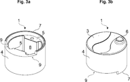
- Figure 3a – is a schematic perspective rear view of the piston head according to another embodiment of the present invention with a single cut out formed in the rim flange;
- Figure 3b – is a schematic perspective front view of the piston head shown in Fig. 3a;
- Figure 4a – is a schematic side view of a stack of a plurality of piston heads shown in Figs. 2a and 2b, prior to subjecting their cylindrical lateral sections to a centerless grinding process without using any dummies;
- Figure 4b – is a schematic cross sectional side view of the stack of the plurality of piston heads shown in Fig. 4a, taken along the line A-A;
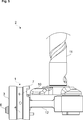
- Figure 5 – is a schematic partial side view of a reciprocating compressor which includes the piston head shown in Figs. 2a and 2b.
- the piston head (1) is suitable for use in a reciprocating compressor (2) (Fig. 5).
- the piston head (1) comprises a cylindrical body which includes: an upper base section (3), a cylindrical lateral section (4) and a lower base section (5) (Figs. 1 to 3).
- the upper base section (3) is leveled but has a projection portion (6) for releasably fitting into a discharge port (not shown) (Fig. 5).
- the lower base section (5) has an annular rim flange (7) (Figs. 1 to 3).
- the upper surface of the annular rim flange (7) is also leveled (Fig. 4).
- the annular rim flange (7) has a height h which is at least equal to a height h ⁇ of the projection portion (6) (Fig. 4).
- the height h and the height h ⁇ are both defined in a direction parallel to a rotational axis of the cylindrical lateral section (4).
- the projection portion (6) of the upper base section (3) is located directly above a region of the lower base section (5), which is enclosed by an inner side of the annular rim flange (7) (Fig. 4).
- the annular rim flange (7) extends in a direction parallel to a rotational axis of the cylindrical lateral section (4) (Fig. 4).
- An outer surface of the annular rim flange (7) is flush with an outer surface of the cylindrical lateral section (4) (Fig. 4).
- the upper surface of the annular rim flange (7) is leveled parallel to a surface of the upper base section (3) and also vertical to the rotational axis of the cylindrical lateral section (4) (Fig. 4).
- a piston heads (1) can be stably stacked on top of another piston head (1) for the purpose of centerless grinding, polishing or the like (Fig. 4).
- the annular rim flange (7) includes one or more than one cut out (9) which defines a passage for a counterweight (10) of a crankshaft (11) (Fig. 5).
- the piston head has two equally shaped cut outs (Fig. 2). These two cut outs define a passage for the counterweight (10) as it swings nearby the piston head (1) (Fig. 5).
- a portion of the annular rim flange (7) separates the two cut-outs (9) (Fig. 2).
- the two cut outs (9) are symmetrically located with respect to a vertical diametric line bisecting the piston head (1) (Fig. 5).
- the piston head (1) has a single cut out (Fig. 3).
- the single cut out (9) similarly defines a passage for the counterweight (10) as it swings nearby the piston head (1). This passage is bound by the annular rim flange (7) only from below. Therefore, the single cut out (9) can accommodate a more massive counterweight (10) which e.g., extends upwards.
- the single cut out (9) is symmetrically located with respect to a vertical diametric line bisecting the piston head (1).
- the lower base section (5) includes a cavity (8) (Figs. 1 to 4). Thereby, a weight of the piston head and, thus, a load on the electrical motor (not shown) are reduced.
- the piston rod (12) is pivotably coupled to the piston head (1) through a pin (not shown) which is arranged within the cavity (8).
- a ball pivot (not shown) is used instead of the pin.
- the piston head (1) is made of metal. In another alternative embodiment, the piston head (1) is made of ceramic or composite material
- the reciprocating compressor (2) of the present invention is suitable for use in a refrigeration appliance, in particular a domestic refrigerator (not shown) (Fig. 5).
- the reciprocating compressor (2) comprises: a cylinder block (not shown) which has a chamber (not shown) for compressing a refrigerant and a piston mechanism for compressing the refrigerant in the chamber (Fig. 5).
- the piston mechanism includes: a piston head (1) of the present invention; a piston rod (12) which is pivotably coupled to the piston head (1) and a crank shaft (11) which has a counterweight (10) and an electrical motor (not shown) for driving the crankshaft (11).
- the piston head (1) is arranged to reciprocate in the chamber.
- the crankshaft (11) is pivotably coupled to the piston rod (12) (Fig. 5).
- the refrigeration appliance (not shown) of the present invention comprises: one or more than one refrigeration compartment for refrigerating item and a refrigeration circuit which includes a reciprocating compressor (2) of the present invention, a condenser, an expansion valve or the like, and one or more than one evaporator which are serially connected to circulate a refrigerant.
- the refrigeration appliance is a domestic refrigerator (not shown) which has a freezer compartment and a cooling compartment.
- the method comprises: a step of forming from a raw material a cylindrical body which includes: an upper base section (3), a cylindrical lateral section (4) and a lower base section (5), wherein the upper base section (3) is leveled but has a projection portion (6) for releasably fitting into an discharge port (Figs. 1 to 3; Fig. 5).
- annular rim flange (7) is formed on the lower base section (5) (Figs. 1 to 3).
- An upper surface of the annular rim flange (7) is leveled.
- the annular rim flange (7) has a height h which is equal to or higher than a height h ⁇ of the projection portion (6) (Fig. 4).
- the projection portion (6) of the upper base section (3) is formed directly above a region of the lower base section (5), which is enclosed by an inner side of the annular rim flange (7) (Figs. 1 to 4).
- one or more than one cut out (9) is formed in the annular rim flange (7).
- the cut outs (9) define a passage for a counterweight (10) of a crankshaft (11) (Figs. 2 to 3; Fig. 5).
- the size, shape and location of the cut outs (9) in the rim flange (7) are determined in accordance with the size, shape, and location of the counterweight (10) of the crankshaft (11) (Fig. 5).
- a cavity (8) is formed into the lower base section (5).
- the cylindrical body including the projection portion (6), the annular rim flange (7), and the cavity (8) is integrally formed through a die forging process.
- the cylindrical body including the projection portion (6), the annular rim flange (7), and the cavity (8) is integrally formed through a cast molding process.
- each cut out (9) is also formed through said die forging process or said cast molding process.
- each cut out (9) is formed through a machining process subsequent to said die forging process or said cast molding process.
- annular rim flange (7) and the cut outs (9) are formed through the machining process subsequent to the die forging process or the cast molding process.
- the method further comprises a step of centerless grinding of the cylindrical lateral sections (4) of a plurality of cylindrical bodies which are stacked on top of each other.
- no dummies are placed in-between the plurality of piston heads (1) (Fig. 4).
- the presence of the cut outs (9) does not hamper the centerless grinding process to be carried out without dummies since in the stacked configuration, the upper surface of the annular rim flange uniformly abuts against the surface of the upper base section (3). Therefore, the piston heads (1) can stably roll during the grinding process.
- the projection portion (6) of the upper base section (3) is stowed away into the space enclosed by the annular rim flange (7) of the adjacent piston head (1). Therefore, the need of using dummies is completely obviated.
- the piston head (1) can be manufactured with the requisite shape and number of cut outs so as to allow a proper counterweight (10) to be mounted to the crankshaft (11).
- the piston heads (1) can be stackwise grinded by a centerless grinding process without using any dummies despite of the projection portion and the cut outs.
Landscapes
- Engineering & Computer Science (AREA)
- Mechanical Engineering (AREA)
- General Engineering & Computer Science (AREA)
- Manufacturing & Machinery (AREA)
- Compressor (AREA)
Abstract
Description
Figure 1b – is a schematic perspective front view of the piston head shown in Fig. 1a;
- Piston head
- Reciprocating compressor
- Upper base section
- Lateral section
- Lower base section
- Projection portion
- Rim flange
- Cavity
- Cut out
- Counterweight
- Crankshaft
- Piston rod
Claims (13)
- A method of producing a piston head (1) for use in a reciprocating compressor (2), the method comprising:a step of forming from a raw material a cylindrical body which includes an upper base section (3), a cylindrical lateral section (4) and a lower base section (5), wherein the upper base section (3) is leveled but has a projection portion (6) for releasably fitting into a discharge port,characterized in thatin the forming step an annular rim flange (7) is formed on the lower base section (5),wherein an upper surface of the annular rim flange (7) is also leveled,wherein the annular rim flange (7) has a height h which is equal to or higher than height h´ of the projection portion (6), andwherein the projection portion (6) is formed directly above a region of the lower base section (5), which is enclosed by an inner side of the annular rim flange (7).
- The method according to claim 1, characterized in that in the forming stepone or more than one cut out (9) is formed in the annular rim flange (7), wherein said one or more than one cut out (9) defines a passage for a counterweight (10) of a crankshaft (11).
- The method according to claim 1 or 2, characterized in that in the forming step a cavity (8) is formed into the lower base section (5).
- The method according to claim 3, characterized in that in the forming step the cylindrical body including the projection portion (6), the annular rim flange (7), and the cavity (8) are together formed through a die forging process or a cast molding process.
- The method according to claim 4, characterized in that in the forming step, said one or more than one cut out (9) is also formed through said die forging process or said cast molding process.
- The method according to claim 4, where dependent on claim 2, characterized in that in the forming step said one or more than one cut (9) is formed through a machining process subsequent to said die forging process or said cast molding process.
- The method according to any one of claims 1 to 6, further comprising a step of centerless grinding of the cylindrical lateral sections (4) of a plurality of cylindrical bodies which are stacked upon each other without placing dummies in-between the cylindrical bodies.
- A piston head (1) for use in a reciprocating compressor (2), the piston head (1) comprisinga cylindrical body which includes an upper base section (3), a cylindrical lateral section (4) and a lower base section (5), wherein the upper base section (3) is leveled but has a projection portion (6) for releasably fitting into a discharge port,characterized in thatthe lower base section (5) has an annular rim flange (7),wherein the upper surface of the annular rim flange (7) is leveled,wherein the annular rim flange (7) has a height h which is at least equal to height h´ of the projection portion (7), andwherein the projection portion (6) is located directly above a region of the lower base section (5) which is enclosed by an inner side of the annular rim flange (7).
- The piston head (1) according to claim 8, characterized in that the annular rim flange (7) includes one or more than one cut out (9) which defines a passage for a counterweight (10) of a crankshaft (11).
- The piston head (1) according to claim 8 or 9, characterized in that the lower base section includes a cavity (8).
- The piston head according to any one of claims 9 to 10, characterized in that said raw material is metal.
- A reciprocating compressor (2) for use in a refrigeration appliance, in particular a domestic refrigerator, the compressor (2) comprisinga cylinder block which has a chamber for compressing a refrigerant,a piston mechanism for compressing the refrigerant in the chamber, wherein the piston mechanism includes a piston head (1) according to any one of claims 8 to 11, the piston head being arranged to reciprocate in the chamber; a piston rod (12) pivotably coupled to the piston head (1) and a crank shaft (11) which has a counter weight (10), the crankshaft (11) being pivotably coupled to the piston rod (12) andan electrical motor for driving the crankshaft (11).
- A refrigeration appliance, in particular a domestic refrigerator comprisinga refrigeration compartment for refrigerating items anda refrigeration circuit including: a reciprocating compressor (2) according to claim 12, a condenser, an expansion valve or the like and an evaporator serially connected to circulate a refrigerant.
Priority Applications (4)
| Application Number | Priority Date | Filing Date | Title |
|---|---|---|---|
| BR112016015104A BR112016015104A2 (en) | 2013-12-26 | 2013-12-26 | piston head for use in an alternating motion compressor and method for producing it. |
| PCT/EP2013/078009 WO2015096869A1 (en) | 2013-12-26 | 2013-12-26 | Piston head for use in a reciprocating compressor and method of producing the same |
| CN201380081892.6A CN106062362A (en) | 2013-12-26 | 2013-12-26 | Piston head for use in a reciprocating compressor and method of producing the same |
| EP13814171.8A EP3090176A1 (en) | 2013-12-26 | 2013-12-26 | Piston head for use in a reciprocating compressor and method of producing the same |
Applications Claiming Priority (1)
| Application Number | Priority Date | Filing Date | Title |
|---|---|---|---|
| PCT/EP2013/078009 WO2015096869A1 (en) | 2013-12-26 | 2013-12-26 | Piston head for use in a reciprocating compressor and method of producing the same |
Publications (1)
| Publication Number | Publication Date |
|---|---|
| WO2015096869A1 true WO2015096869A1 (en) | 2015-07-02 |
Family
ID=49883117
Family Applications (1)
| Application Number | Title | Priority Date | Filing Date |
|---|---|---|---|
| PCT/EP2013/078009 WO2015096869A1 (en) | 2013-12-26 | 2013-12-26 | Piston head for use in a reciprocating compressor and method of producing the same |
Country Status (4)
| Country | Link |
|---|---|
| EP (1) | EP3090176A1 (en) |
| CN (1) | CN106062362A (en) |
| BR (1) | BR112016015104A2 (en) |
| WO (1) | WO2015096869A1 (en) |
Citations (3)
| Publication number | Priority date | Publication date | Assignee | Title |
|---|---|---|---|---|
| GB276541A (en) * | 1926-11-30 | 1927-09-01 | Westinghouse Air Brake Co | Improvements in or relating to fluid compressors |
| WO2000045988A1 (en) * | 1999-02-02 | 2000-08-10 | Amcast Industrial Corporation | A process for producing variable displacement compressor pistons having hollow piston bodies and integral actuator rods |
| US6532655B1 (en) * | 1999-03-20 | 2003-03-18 | Halla Climate Control Corp. | Method of manufacturing hollow piston for compressors |
Family Cites Families (2)
| Publication number | Priority date | Publication date | Assignee | Title |
|---|---|---|---|---|
| CN2270814Y (en) * | 1996-07-12 | 1997-12-17 | 季晓初 | Reciprocating piston with piston ring |
| DE102010033882A1 (en) * | 2010-08-10 | 2012-02-16 | Mahle International Gmbh | Piston for an internal combustion engine |
-
2013
- 2013-12-26 BR BR112016015104A patent/BR112016015104A2/en not_active IP Right Cessation
- 2013-12-26 WO PCT/EP2013/078009 patent/WO2015096869A1/en active Application Filing
- 2013-12-26 EP EP13814171.8A patent/EP3090176A1/en not_active Withdrawn
- 2013-12-26 CN CN201380081892.6A patent/CN106062362A/en active Pending
Patent Citations (3)
| Publication number | Priority date | Publication date | Assignee | Title |
|---|---|---|---|---|
| GB276541A (en) * | 1926-11-30 | 1927-09-01 | Westinghouse Air Brake Co | Improvements in or relating to fluid compressors |
| WO2000045988A1 (en) * | 1999-02-02 | 2000-08-10 | Amcast Industrial Corporation | A process for producing variable displacement compressor pistons having hollow piston bodies and integral actuator rods |
| US6532655B1 (en) * | 1999-03-20 | 2003-03-18 | Halla Climate Control Corp. | Method of manufacturing hollow piston for compressors |
Also Published As
| Publication number | Publication date |
|---|---|
| EP3090176A1 (en) | 2016-11-09 |
| CN106062362A (en) | 2016-10-26 |
| BR112016015104A2 (en) | 2017-10-10 |
Similar Documents
| Publication | Publication Date | Title |
|---|---|---|
| US9803641B2 (en) | Method for manufacturing anti-rotation ring of scroll type compressor and anti-rotation mechanism of the scroll type compressor | |
| US20080136280A1 (en) | Motor mechanism of DC inverter-fed compressor | |
| CN105570090A (en) | Split type crankcase for refrigerator compressor | |
| CN104963868A (en) | Rotary compressor and crankshaft thereof | |
| CN205503402U (en) | Split type crankcase is used to refrigerator compressor | |
| CN206299566U (en) | Rotary compressor and freezing cycle device | |
| WO2015096869A1 (en) | Piston head for use in a reciprocating compressor and method of producing the same | |
| US20040016122A1 (en) | Method of manufacturing crankshaft for a hermetic reciprocating compressor | |
| CN105114315A (en) | Multi-cylinder rotating type compressor | |
| CN205036580U (en) | Multi -cylinder rotary compressor | |
| CN205689385U (en) | Compressor crankcase and there is its compressor, refrigerator | |
| US20110176942A1 (en) | Sealed compressor | |
| CN105864047B (en) | Rotary compressor casing assembly, rotary compressor and refrigeration system | |
| CN101192766B (en) | Motor mechanism for DC frequency conversion compressor | |
| CN104121166A (en) | Two-cylinder compressor and air conditioner with same | |
| CN203272143U (en) | Rotary compressor | |
| WO2006109975A2 (en) | Method for making a crank shaft | |
| JP6204759B2 (en) | Hermetic compressor | |
| CN207139011U (en) | A kind of ream crankcase stator pin special purpose device | |
| CN207212924U (en) | Parts of bearings and there is its compressor, refrigerating plant | |
| CN104533756A (en) | Air compressor crankshaft and manufacturing process thereof | |
| CN204783677U (en) | Rotary compressor and bent axle thereof | |
| CN202659440U (en) | Air cylinder base for sealed refrigeration compressor and combination of same with crankshaft | |
| CN206770165U (en) | Compressor | |
| KR20120006424A (en) | Hermetic type compressor and refrigerator with the same |
Legal Events
| Date | Code | Title | Description |
|---|---|---|---|
| 121 | Ep: the epo has been informed by wipo that ep was designated in this application |
Ref document number: 13814171 Country of ref document: EP Kind code of ref document: A1 |
|
| NENP | Non-entry into the national phase |
Ref country code: DE |
|
| REEP | Request for entry into the european phase |
Ref document number: 2013814171 Country of ref document: EP |
|
| WWE | Wipo information: entry into national phase |
Ref document number: 2013814171 Country of ref document: EP |
|
| REG | Reference to national code |
Ref country code: BR Ref legal event code: B01A Ref document number: 112016015104 Country of ref document: BR |
|
| ENP | Entry into the national phase |
Ref document number: 112016015104 Country of ref document: BR Kind code of ref document: A2 Effective date: 20160627 |