WO2015092942A1 - Electronic device - Google Patents
Electronic device Download PDFInfo
- Publication number
- WO2015092942A1 WO2015092942A1 PCT/JP2013/084375 JP2013084375W WO2015092942A1 WO 2015092942 A1 WO2015092942 A1 WO 2015092942A1 JP 2013084375 W JP2013084375 W JP 2013084375W WO 2015092942 A1 WO2015092942 A1 WO 2015092942A1
- Authority
- WO
- WIPO (PCT)
- Prior art keywords
- unit
- electronic device
- connecting portion
- input
- coupled
- Prior art date
Links
Images


Classifications
-
- G—PHYSICS
- G06—COMPUTING; CALCULATING OR COUNTING
- G06F—ELECTRIC DIGITAL DATA PROCESSING
- G06F1/00—Details not covered by groups G06F3/00 - G06F13/00 and G06F21/00
- G06F1/16—Constructional details or arrangements
- G06F1/1613—Constructional details or arrangements for portable computers
- G06F1/1633—Constructional details or arrangements of portable computers not specific to the type of enclosures covered by groups G06F1/1615 - G06F1/1626
- G06F1/1637—Details related to the display arrangement, including those related to the mounting of the display in the housing
-
- G—PHYSICS
- G06—COMPUTING; CALCULATING OR COUNTING
- G06F—ELECTRIC DIGITAL DATA PROCESSING
- G06F1/00—Details not covered by groups G06F3/00 - G06F13/00 and G06F21/00
- G06F1/16—Constructional details or arrangements
- G06F1/1613—Constructional details or arrangements for portable computers
- G06F1/1615—Constructional details or arrangements for portable computers with several enclosures having relative motions, each enclosure supporting at least one I/O or computing function
- G06F1/1616—Constructional details or arrangements for portable computers with several enclosures having relative motions, each enclosure supporting at least one I/O or computing function with folding flat displays, e.g. laptop computers or notebooks having a clamshell configuration, with body parts pivoting to an open position around an axis parallel to the plane they define in closed position
-
- G—PHYSICS
- G06—COMPUTING; CALCULATING OR COUNTING
- G06F—ELECTRIC DIGITAL DATA PROCESSING
- G06F1/00—Details not covered by groups G06F3/00 - G06F13/00 and G06F21/00
- G06F1/16—Constructional details or arrangements
- G06F1/1613—Constructional details or arrangements for portable computers
- G06F1/1633—Constructional details or arrangements of portable computers not specific to the type of enclosures covered by groups G06F1/1615 - G06F1/1626
- G06F1/1637—Details related to the display arrangement, including those related to the mounting of the display in the housing
- G06F1/1654—Details related to the display arrangement, including those related to the mounting of the display in the housing the display being detachable, e.g. for remote use
-
- G—PHYSICS
- G06—COMPUTING; CALCULATING OR COUNTING
- G06F—ELECTRIC DIGITAL DATA PROCESSING
- G06F1/00—Details not covered by groups G06F3/00 - G06F13/00 and G06F21/00
- G06F1/16—Constructional details or arrangements
- G06F1/1613—Constructional details or arrangements for portable computers
- G06F1/1633—Constructional details or arrangements of portable computers not specific to the type of enclosures covered by groups G06F1/1615 - G06F1/1626
- G06F1/1656—Details related to functional adaptations of the enclosure, e.g. to provide protection against EMI, shock, water, or to host detachable peripherals like a mouse or removable expansions units like PCMCIA cards, or to provide access to internal components for maintenance or to removable storage supports like CDs or DVDs, or to mechanically mount accessories
- G06F1/166—Details related to functional adaptations of the enclosure, e.g. to provide protection against EMI, shock, water, or to host detachable peripherals like a mouse or removable expansions units like PCMCIA cards, or to provide access to internal components for maintenance or to removable storage supports like CDs or DVDs, or to mechanically mount accessories related to integrated arrangements for adjusting the position of the main body with respect to the supporting surface, e.g. legs for adjusting the tilt angle
-
- G—PHYSICS
- G06—COMPUTING; CALCULATING OR COUNTING
- G06F—ELECTRIC DIGITAL DATA PROCESSING
- G06F1/00—Details not covered by groups G06F3/00 - G06F13/00 and G06F21/00
- G06F1/16—Constructional details or arrangements
- G06F1/1613—Constructional details or arrangements for portable computers
- G06F1/1633—Constructional details or arrangements of portable computers not specific to the type of enclosures covered by groups G06F1/1615 - G06F1/1626
- G06F1/1662—Details related to the integrated keyboard
- G06F1/1669—Detachable keyboards
-
- G—PHYSICS
- G06—COMPUTING; CALCULATING OR COUNTING
- G06F—ELECTRIC DIGITAL DATA PROCESSING
- G06F1/00—Details not covered by groups G06F3/00 - G06F13/00 and G06F21/00
- G06F1/16—Constructional details or arrangements
- G06F1/1613—Constructional details or arrangements for portable computers
- G06F1/1633—Constructional details or arrangements of portable computers not specific to the type of enclosures covered by groups G06F1/1615 - G06F1/1626
- G06F1/1675—Miscellaneous details related to the relative movement between the different enclosures or enclosure parts
- G06F1/1681—Details related solely to hinges
Definitions
- Embodiments described herein relate generally to an electronic device.
- An electronic device such as a portable computer has input devices such as a keyboard, a touch pad, and a pointing stick.
- the input device is coupled to a display device such as a liquid crystal display (LCD) for displaying images.
- LCD liquid crystal display
- One of the problems to be solved by the present invention is to provide an electronic device used in a plurality of modes.
- An electronic device includes a first part, a second part, and a hinge part.
- the first portion includes a first surface, a second surface located on the opposite side of the first surface, and a first surface located between the first surface and the second surface.
- the second portion is detachable from a third end and a connecting portion having a fourth end located on the opposite side of the third end, and the fourth end of the connecting portion.
- an input portion having a fifth end coupled.
- the hinge portion is movable between the first position where the second portion covers the display portion and the second position where the second portion covers the second surface.
- the first end of the first portion and the third end of the connecting portion are coupled.
- FIG. 1 is a perspective view showing a portable computer according to one embodiment.
- FIG. 2 is a perspective view showing the portable computer of one embodiment from another direction.
- FIG. 3 is a side view of a portable computer according to one embodiment.
- FIG. 4 is a perspective view showing the portable computer of one embodiment except for a part of the first to third housings.
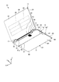
- FIG. 5 is a perspective view showing a display unit and a base unit according to one embodiment.
- FIG. 6 is a rear view showing the keyboard module of one embodiment.
- FIG. 7 is a side view showing a part of a tablet mode portable computer according to one embodiment.
- FIG. 8 is a side view showing a separate-mode portable computer according to one embodiment.
- FIG. 9 is a side view illustrating a tent mode portable computer according to one embodiment.
- the user side is the front
- the side far from the user is the rear
- the left side when viewed from the user is the left direction
- the right side when viewed from the user is the right direction
- the upper side when viewed from the user is upward
- the downward direction when viewed from the user is defined as the downward direction.
- a plurality of expressions may be written together for the constituent elements according to the embodiment and the description of the elements. It is not precluded that other expressions not described in the component and description are made. Furthermore, it is not prevented that other expressions are given for the components and descriptions in which a plurality of expressions are not described.
- FIG. 1 is a perspective view showing the portable computer 10.
- FIG. 2 is a perspective view showing the portable computer 10 from another direction.
- FIG. 3 is a side view of the portable computer 10.
- the portable computer 10 is an example of an electronic device.
- the electronic device is not limited to the portable computer 10 and may be various devices such as a personal computer, a television receiver, a display, a tablet, a mobile phone, a smartphone, a portable game machine, and a camera.
- the portable computer 10 includes a display unit 11, a base unit 12, and two hinge units 13.
- the display unit 11 is an example of a first portion, and may be referred to as a display unit, a module, or a unit, for example.
- the base portion 12 is an example of a second portion, and may be referred to as a main body, a module, or a unit, for example.
- the hinge part 13 can also be called a connection part, a coupling part, a rotation part, an intermediate part, or an interposition part, for example.
- an X axis, a Y axis, and a Z axis are defined.
- the X axis, the Y axis, and the Z axis are orthogonal to each other.
- the X axis is, for example, along the width (length in the longitudinal direction) of the base portion 12.
- the Y axis is, for example, along the depth (length in the short direction) of the base portion 12.
- the Z axis is, for example, along the thickness (length in the vertical direction) of the base portion 12.
- the display unit 11 includes a first housing 21 and a display module 22. As shown in FIG. 2, the display unit 11 further includes a plurality of first batteries 23.
- the first housing 21 may be referred to as an exterior part, a member, or a wall, for example.
- the display module 22 may also be referred to as a display device, a display unit, a component, or a member, for example.
- the first casing 21 is formed in a flat, substantially rectangular parallelepiped box shape.
- the first housing 21 is basically formed of, for example, a magnesium alloy. Note that the first housing 21 may be formed of other materials.
- the first housing 21 has a front surface 31, a back surface 32, a lower end portion 33, and an upper end portion 34.
- the front surface 31 is an example of a first surface.
- the back surface 32 is an example of a second surface.
- the lower end 33 is an example of a first end.
- the upper end portion 34 is an example of a second end portion.
- the lower end 33 and the upper end 34 may also be referred to as ends, edges, or parts, for example.
- the front surface 31 is formed in a substantially flat rectangular shape.
- the front surface 31 is formed of, for example, a transparent glass plate that covers a bezel (frame).
- a display opening 36 is formed in the bezel.
- the display opening 36 is a substantially rectangular hole.
- the display opening 36 is closed by the glass plate.
- the back surface 32 is located on the opposite side of the front surface 31.
- the lower end 33 includes an end surface of the first casing 21 located between the lower edge of the front surface 31 and the lower edge of the back surface 32.
- the end surface intersects the front surface 31 and the back surface 32.
- the upper end 34 is located on the opposite side of the lower end 33.
- the upper end portion 34 includes an end surface of the first housing 21 located between the upper edge of the front surface 31 and the upper edge of the back surface 32. The end surface intersects the front surface 31 and the back surface 32.
- the display module 22 is, for example, a capacitive in-cell touch panel.
- the display module 22 is not limited to this, and may be another component that displays an image, such as a liquid crystal display (LCD) or an organic electroluminescence (OEL) display to which a touch panel is attached.
- LCD liquid crystal display
- OEL organic electroluminescence
- the display module 22 is accommodated in the first casing 21.
- the display module 22 has a screen 22a.
- the screen 22a is an example of a display unit, and may be referred to as a display surface or a part.
- the screen 22a is exposed to the outside of the first casing 21 through the display opening 36 and the glass plate, and displays an image. That is, the screen 22 a of the display module 22 displays an image on the front surface 31.
- an image includes a still image, a moving image, and a monochrome screen.
- the display module 22 detects a user's finger touched by the glass plate covering the screen 22a or the display opening 36, for example.
- the display module 22 is operated by the user's finger to input information to the portable computer 10. That is, the display module 22 is not only a display device but also an input device.
- the first battery 23 is accommodated in the first housing 21.
- the first battery 23 is, for example, a lithium ion secondary battery.
- the first battery 23 may be another type of battery.
- the first battery 23 is a power source for the portable computer 10.
- the base unit 12 includes a base unit 41 and a keyboard module 42.
- the base unit 41 is an example of a connecting portion, and may be referred to as, for example, a connecting portion, a docking portion, a rotating portion, a supporting portion, a part, or a part.
- the keyboard module 42 is an example of an input unit, and may be referred to as, for example, a coupling unit, a docking unit, a detaching unit, a part, or a component.
- the base unit 41 has a second casing 51 and a power button 52.
- the second housing 51 can also be referred to as an exterior part, a member, or a wall, for example.
- the power button 52 is an example of an activation unit, and may be referred to as a button or an operation unit, for example.
- the second casing 51 is formed in a flat, substantially rectangular parallelepiped box shape.
- the second housing 51 is basically formed of, for example, a magnesium alloy. Note that the second casing 51 may be formed of other materials.
- the second housing 51 has a first upper surface 54, a first lower surface 55, a first rear end portion 56, a first front end portion 57, and two first side surfaces 58. .
- the first lower surface 55 is an example of a fifth surface.
- the first rear end portion 56 is an example of a third end portion.
- the first front end portion 57 is an example of a fourth end portion.
- the first rear end portion 56 and the first front end portion 57 may be referred to as ends, edges, or portions, for example.
- the first upper surface 54 is formed in a substantially flat rectangular shape.
- a plurality of holes 61 are provided in the first upper surface 54.
- the base unit 41 is further housed in the second housing 51 and further includes a speaker that emits sound through the plurality of holes 61.
- the first lower surface 55 is located on the opposite side of the first upper surface 54.
- a plurality of first legs 62 are provided on the first lower surface 55.
- the first legs 62 are, for example, synthetic rubber protrusions protruding from the first lower surface 55. As shown in FIG. 3, the first leg 62 is in contact with the placement surface S on which the portable computer 10 is placed and supports the base unit 41.
- the placement surface S is, for example, the upper surface of a desk.
- a plurality of air inlets 63 are provided on the first lower surface 55.
- the intake port 63 is an example of a first ventilation port, and may be referred to as a hole or an opening, for example.
- the air inlet 63 communicates with the inside of the second housing 51.
- the first rear end portion 56 includes an end surface of the second casing 51 located between the rear edge of the first upper surface 54 and the rear edge of the first lower surface 55.
- the end surface intersects the first upper surface 54 and the first lower surface 55.
- a plurality of exhaust ports 64 are provided in the first rear end portion 56.
- the exhaust port 64 is an example of a second vent hole, and may be referred to as a hole, an opening, or a slit, for example.
- the exhaust port 64 leads to the inside of the second housing 51.
- the first front end portion 57 is located on the opposite side of the first rear end portion 56.
- the first front end portion 57 includes an end surface of the second casing 51 located between the front edge of the first upper surface 54 and the front edge of the first lower surface 55. The end surface intersects the first upper surface 54 and the first lower surface 55.
- the two first side surfaces 58 are located between the right and left edges of the first upper surface 54 and the right and left edges of the first lower surface 55, respectively.
- the first side surface 58 is formed in a line-symmetric shape with respect to the center between the first upper surface 54 and the first lower surface 55 in the thickness direction (the direction along the Z axis) of the second housing 51. Is done.
- the first side surface 58 is, for example, an arcuate curved surface.
- the start button 52 is provided on one first side surface 58.
- the portable computer 10 is activated.
- the activation of the portable computer 10 is not limited to the operation of the portable computer 10 (power on), but includes, for example, recovery from the hibernation state of the portable computer 10.
- the keyboard module 42 includes a third casing 71, a keyboard 72, a pointing stick 73, a button 74, and an eject lever 75.
- the keyboard 72, the pointing stick 73, and the button 74 are examples of an operation unit, and may be referred to as, for example, an input unit, an input device, or an interface.
- the eject lever 75 is an example of a release unit, and may be referred to as a slide unit or an operation unit, for example.
- the third casing 71 is formed in a flat, substantially rectangular parallelepiped box shape.
- the third casing 71 is basically formed of, for example, a magnesium alloy. Note that the third casing 71 may be formed of other materials.
- the third casing 71 has a second upper surface 81, a second lower surface 82, a second rear end portion 83, a second front end portion 84, and two second side surfaces 85.
- the second upper surface 81 is an example of a third surface.
- the second lower surface 82 is an example of a fourth surface.
- the second rear end portion 83 is an example of a fifth end portion.
- the second front end portion 84 is an example of a sixth end portion.
- the second rear end 83 and the second front end 84 may also be referred to as ends, edges, or portions, for example.
- the second upper surface 81 is formed in a rectangular shape having a recess 81a.
- a keyboard 72, a pointing stick 73, a button 74, and an eject lever 75 are provided on the second upper surface 81.
- the keyboard 72 and the pointing stick 73 are located in the recess 81a.
- the keyboard 72, pointing stick 73, and button 74 are operated by the user to input information to the portable computer 10.
- the eject lever 75 is located between the keyboard 72 and the button 74.
- the second lower surface 82 is located on the opposite side of the second upper surface 81.
- a plurality of second legs 87 are provided on the second lower surface 82.
- the second legs 87 are, for example, synthetic rubber protrusions protruding from the second lower surface 82. As shown in FIG. 3, the second leg 87 is in contact with the placement surface S on which the portable computer 10 is placed and supports the keyboard module 42.
- the second rear end portion 83 includes an end surface of the second casing 51 located between the rear edge of the second upper surface 81 and the rear edge of the second lower surface 82.
- the end surface intersects the second upper surface 81 and the second lower surface 82.
- the second front end portion 84 is located on the opposite side of the second rear end portion 83.
- the second front end portion 84 includes an end surface of the second casing 51 located between the front edge of the second upper surface 81 and the front edge of the second lower surface 82.
- the end surface intersects the second upper surface 81 and the second lower surface 82.
- the button 74 is adjacent to the second front end 84.
- a plurality of third legs 88 are provided at the second front end portion 84.
- the third legs 88 are, for example, synthetic rubber protrusions protruding from the end surfaces of the second upper surface 81, the second lower surface 82, and the second front end portion 84. As shown in FIG. 3, the third leg 88 is in contact with the placement surface S on which the portable computer 10 is placed and supports the keyboard module 42.
- the two second side surfaces 85 are located between the right and left edges of the second upper surface 81 and the right and left edges of the second lower surface 82, respectively.
- the second side surface 85 is formed in a line-symmetric shape with respect to the center of the second upper surface 81 and the second lower surface 82 in the thickness direction (the direction along the Z axis) of the second casing 71.
- the second side surface 85 is, for example, an arcuate curved surface having the same polarity radius as that of the first side surface 58.
- FIG. 4 is a perspective view of the portable computer 10 excluding a part of the first casing 21, the second casing 51, and the third casing 71.
- the base unit 41 further includes a substrate 91, a first communication unit 92, a cooling unit 93, and a plurality of input / output components 94.
- the substrate 91 is an example of a module, and may be referred to as a component, for example.
- the substrate 91, the first communication unit 92, the cooling unit 93, and the input / output component 94 are accommodated in the second casing 51.
- the substrate 91, the first communication unit 92, the cooling unit 93, and the input / output component 94 may be accommodated in the first casing 21 of the display unit 11, for example.
- the substrate 91 is, for example, a printed circuit board (PCB).
- the substrate 91 may be another substrate such as a flexible printed circuit board (FPC), and the module may be another component.
- Various electronic components such as a central processing unit (CPU) and a memory are mounted on the substrate 91.
- the first communication unit 92 performs short-range wireless communication, for example.
- the first communication unit 92 includes, for example, a circuit board on which various electronic components are mounted and an antenna.
- the first communication unit 92 is electrically connected to the substrate 91 and transmits and receives electrical signals to and from the CPU, for example.
- the second casing 51 has an antenna cover 51 a that covers the antenna of the first communication unit 92.
- the antenna cover 51a is a part of the second housing 51 formed of an insulating material such as synthetic resin.
- the antenna transmits and receives radio waves through the antenna cover 51a.
- a part of the antenna cover 51 a protrudes from the first upper surface 54 and the first lower surface 55.
- the cooling unit 93 is, for example, a centrifugal fan.
- the cooling unit 93 is thermally connected to the CPU by a heat pipe, for example.
- the cooling unit 93 is at a position corresponding to the intake port 63.
- the cooling unit 93 sucks air outside the third housing 71 through the air inlet 63 and discharges air from the air outlet 64. Thereby, the cooling unit 93 cools the CPU and the inside of the second housing 51.
- the cooling unit 93 may suck outside air from the exhaust port 64 and discharge air from the intake port 63.
- the input / output component 94 is mounted on the substrate 91.
- the input / output component 94 is, for example, a USB connector, a LAN connector, an RGB connector, an audio terminal, a power connector, and a memory card connector.
- the input / output component 94 is exposed to the outside of the second casing 51 through an opening provided in the first side surface 58.
- the keyboard module 42 further includes a second communication unit 97 and a second battery 98.
- the second battery 98 is an example of a battery, and may be referred to as a power source, a charge / discharge unit, or a power feeding unit, for example.
- the second communication unit 97 and the second battery 98 are accommodated in the third casing 71.
- the second communication unit 97 performs short-range wireless communication with the first communication unit 92, for example.
- the second communication unit 97 includes, for example, a circuit board on which various electronic components are mounted and an antenna.
- the second communication unit 97 receives electrical signals from the keyboard 72, pointing stick 73, and button 74.
- the keyboard module 42 inputs information to the CPU of the substrate 91, for example, via the first communication unit 92 and the second communication unit 97.
- the second communication unit 97 transmits information input to the keyboard 72 by the user to the first communication unit 92 by short-range wireless communication.
- the first communication unit 92 inputs the received information to the CPU of the substrate 91.
- the first communication unit 92 and the second communication unit 97 are not limited to short-range wireless communication, and may communicate by other methods such as infrared rays.
- the second battery 98 is, for example, a lithium ion secondary battery.
- the second battery 98 may be another type of battery.
- the second battery 98 is a power source for the keyboard module 42.
- FIG. 5 is a perspective view showing a part of the display unit 11 and the base unit 41.
- the first front end portion 57 is provided with two convex portions 101 and a first terminal 102.
- the convex portion 101 is an example of a first fitting portion, and may be referred to as an insertion portion, a support portion, or a reinforcement portion, for example.
- the convex portion 101 is formed in a substantially rectangular plate shape extending in the direction along the X axis.
- the convex portion 101 is a part of the second housing 51, and is formed of a magnesium alloy like the second housing 51. Note that the convex portion 101 may be formed of a material different from that of the second casing 51.
- the convex portion 101 projects from the end face of the first front end portion 57 in the direction along the Y axis.
- the two convex portions 101 are arranged in a direction along the X axis.
- the two convex portions 101 each have a notch 104.
- the notch 104 is an example of a first engagement portion, and may be referred to as, for example, a recess, a depression, or a catch portion.
- the notch 104 is provided at the side end portion 101 a of the convex portion 101.
- the side end portion 101 a is an end portion of the convex portion 101 in the direction along the X axis, and faces the opposite side of the other convex portion 101.
- the first terminal 102 is disposed on the end face of the first front end portion 57.
- the first terminal 102 has, for example, a plurality of positive electrodes and negative electrodes arranged alternately.
- the first terminal 102 is electrically connected to the first battery 23 and the substrate 91.
- the first terminal 102 is located between the two convex portions 101.
- the first terminal 102 is arranged to be shifted to the right or left from the center of the first front end portion 57 in the direction along the X axis (the center between the two first side surfaces 58).
- FIG. 6 is a rear view showing the keyboard module 42.
- the second rear end portion 83 is provided with two concave portions 106 and a second terminal 107.
- the concave portion 106 is an example of a second fitting portion, and may be referred to as an opening, a hole, a slit, or a depression, for example.
- the two recesses 106 are substantially rectangular openings extending in the direction along the X axis.
- the recess 106 is located at the second rear end 83.
- the two concave portions 106 are arranged corresponding to the convex portions 101 and are arranged in a direction along the X axis.
- Hooks 109 are provided in the two recesses 106, respectively.
- the hook 109 is an example of a second engaging portion, and may be referred to as a hooking portion, a fitting portion, a fixing portion, or an attaching portion, for example.
- the hook 109 protrudes in the direction along the X axis from the inner surface of the recess 106 at a position corresponding to the notch 104.
- the hook 109 is movable so as to be retracted from the inner surface of the recess 106.
- the second terminal 107 is disposed on the end face of the second rear end portion 83.
- the second terminal 107 has, for example, a plurality of positive electrodes and negative electrodes arranged alternately.
- the second terminal 107 is electrically connected to the second battery 98.
- the second terminal 107 is located between the two recesses 106.
- the second terminal 107 is arranged to be deviated to the right or left from the center of the second rear end portion 83 in the direction along the X axis (the center between the two second side surfaces 85).
- the second rear end portion 83 of the keyboard module 42 is detachably coupled to the first front end portion 57 of the base unit 41. That is, the keyboard module 42 is coupled to the base unit 41 so as to be aligned with the base unit 41 in a direction from the first rear end portion 56 toward the first front end portion 57 (direction along the Y axis).
- the convex portion 101 fits into the concave portion 106.
- the keyboard module 42 is supported by the base unit 41 by fitting the convex portion 101 into the concave portion 106.
- the hook 109 of the concave part 106 is caught in the notch 104 of the convex part 101.
- the keyboard module 42 is restricted from being removed from the base unit 41 by hooking the hook 109 into the notch 104.
- the two hooks 109 are connected to the eject lever 75 via a plurality of links, for example.
- the hook 109 is detached from the notch 104. In other words, the eject lever 75 operates the hook 109.
- the first terminal 102 is electrically connected to the second terminal 107.
- the second battery 98 is charged via the first and second terminals 102 and 107 that are electrically connected to each other.
- power supplied from an outlet to the power connector of the base unit 41 is supplied to the second battery 98 via the first and second terminals 102 and 107.
- the power of the first battery 23 is supplied to the second battery 98 via the base unit 41 and the first and second terminals 102 and 107.
- the hinge part 13 connects the lower end part 33 of the display part 11 and the first rear end part 56 of the base unit 41.
- One end of the hinge portion 13 is rotatably coupled to the lower end portion 33 of the first housing 21 of the display portion 11.
- the other end portion of the hinge portion 13 is rotatably coupled to the first rear end portion 56 of the second casing 51 of the base unit 41.
- the antenna cover 51a of the second casing 51 is located.
- the hinge part 13 can be rotated 180 degrees between the position of the first housing 21 of the display part 11 protruding vertically from the front surface 31 and the position protruding vertically from the back surface 32. Further, the hinge portion 13 is 180 degrees between the position of the second casing 51 of the base unit 41 that protrudes vertically from the first upper surface 54 and the position that protrudes vertically from the first lower surface 55. It can be rotated. That is, the hinge part 13 couple
- FIG. 7 is a side view showing a part of the portable computer 10 in a state where the base unit 41 is rotated about 360 degrees from the position shown in practice in FIG. 3 (tablet mode).
- the hinge unit 13 rotates the base unit 41 between a first position P1 indicated by a solid line in FIG. 3 and a second position P2 shown in FIG.
- the first position P1 may also be referred to as a closed position.
- the second position P2 may also be referred to as a reverse position.
- the base portion 12 covers the front surface 31 of the first housing 21. For this reason, the base part 12 covers the screen 22 a of the display module 22.
- the first upper surface 54 of the second housing 51 and the second upper surface 81 of the third housing 71 are the front surface 31 of the first housing 21. Opposite to.
- the distance between the lower end portion 33 and the upper end portion 34 of the display unit 11 is longer than the distance between the first rear end portion 56 and the first front end portion 57 of the base unit 41. Further, the distance between the lower end 33 and the upper end 34 of the display unit 11 is substantially equal to the distance between the first rear end 56 of the base unit 41 and the second front end 84 of the keyboard module 42. Are equal.
- the screen 22a of the display module 22 is partially covered by the base unit 41 located at the first position P1. Furthermore, the screen 22a of the display module 22 is partially exposed.
- the base portion 12 covers the back surface 32 of the first housing 21.
- the first lower surface 55 of the second housing 51 faces the back surface 32 of the first housing 21. Furthermore, the screen 22a of the display module 22 is completely exposed.
- the air inlet 63 faces the gap G between the back surface 32 of the first housing 21 and the first lower surface 55 of the second housing 51. That is, the air inlet 63 is opened without being blocked by the first housing 21.
- the cooling unit 93 sucks air in the gap G from the intake port 63.
- the keyboard module 42 in the clamshell mode shown in FIG. 1 is coupled to the base unit 41 in the first direction D1.
- the second upper surface 81 of the third housing 71 is on the front surface 31 of the first housing 21. opposite.
- the keyboard module 42 in the tablet mode shown in FIG. 7 is coupled to the base unit 41 in the second direction D2.
- the second direction D2 is opposite to the first direction D1.
- the second upper surface 81 of the third housing 71 is on the back surface 32 of the first housing 21. opposite.
- the keyboard module 42 is coupled to the base unit 41 in the first direction D1 or the second direction D2. Even if the keyboard module 42 is coupled to the base unit 41 in either the first direction D1 or the second direction D2, the convex portion 101 fits into the concave portion 106 and the hook 109 is caught by the notch 104.
- one first side surface 58 is continuous with one second side surface 85.
- the one first side surface 58 is continuous with the other second side surface 85. That is, the second side surface 85 continues to the first side surface 58 regardless of whether the keyboard module 42 is coupled to the base unit 41 in either the first direction D1 or the second direction D2.
- the first terminal 102 faces the second terminal 107 and is electrically connected.
- the first terminal 102 faces the second rear end 83 of the third casing 71. That is, the electrical connection between the first terminal 101 and the second terminal 107 is released.
- the first and second terminals 102 and 107 do not touch other members. Note that the first and second terminals 102 and 107 may contact the insulating member.
- FIG. 8 is a side view showing the portable computer 10 with the keyboard module 42 removed and the base unit 41 supporting the display unit 11 (separate mode). As shown in FIG. 8, the keyboard module 42 can be used while being detached from the base unit 41.
- the base unit 41 in the separate mode is located between the second position P2 and the third position P3 indicated by a two-dot chain line in FIG.
- the third position P3 is between the first position P1 and the second position P2.
- the first upper surface 54 of the second casing 51 is in contact with the mounting surface S.
- the base unit 41 supports the display unit 11.
- FIG. 9 is a side view showing the portable computer 10 with the keyboard module 42 removed and supported by the base unit 41 and the display unit 11 (tent mode).
- the base unit 41 in the tent mode is located between the second position P2 and the third position P3.
- the upper end portion 34 of the first housing 21 is in contact with the placement surface S.
- the convex portion 101 provided at the first front end portion 57 of the second casing 51 is in contact with the placement surface S. That is, the upper end portion 34 of the display unit 11 and the convex portion 101 of the base unit 41 support the portable computer 10.
- the inclination of the display unit 11 with respect to the placement surface S in the tent mode is shallower than the inclination of the display unit 11 with respect to the placement surface S in the separate mode.
- the lower end 33 is located above the display module 22 and the upper end 34 is located below the display module 22.
- the CPU of the substrate 91 detects that the portable computer 10 is in the tent mode using, for example, an acceleration sensor.
- the screen 22a of the display module 22 displays an image in such a direction that the upper end 34 is located below the image and the lower end 33 is located above the image.
- the lower end 33 is located below the display module 22 and the upper end 34 is located above the display module 22.
- the CPU of the substrate 91 detects that the portable computer 10 is in the clamshell mode.
- the screen 22a of the display module 22 displays an image in such a direction that the upper end 34 is located above the image and the lower end 33 is located below the image.
- the orientation of the image displayed by the display module 22 may be changed, for example, when the user operates the portable computer 10. Further, the CPU of the substrate 91 may detect that the portable computer 10 is in the tent mode, for example, based on an angle at which the hinge portion 13 is rotated.
- the base unit 41 is movably coupled to the display unit 11 by the hinge unit 13.
- a second rear end portion 83 of the keyboard module 42 is detachably coupled to the first front end portion 57 of the base unit 41. Therefore, the keyboard module 42 can be used in a state where it is detached from the base unit 41. Thereby, the portable computer 10 can be used in a plurality of modes.
- the screen 22a of the display module 22 is partially covered and partially exposed by the base unit 41 located at the first position P1. That is, the distance between the first rear end portion 56 and the first front end portion 57 of the base unit 41 is shorter than the distance between the lower end portion 33 and the upper end portion 34 of the display unit 11. For this reason, the portable computer 10 from which the keyboard module 42 is removed can be reduced in size.
- the keyboard module 42 is coupled to the base unit 41 in the first direction D1 and the second direction D2. Therefore, for example, when the portable computer 10 is used in the tablet mode, the keyboard 72 is hidden by the display unit 11 when the keyboard module 42 is coupled to the base unit 41 in the second direction D2. As a result, erroneous operation of the keyboard 72 is suppressed. Since the keyboard 72 is provided in the recess 81 a of the second upper surface 81, the keyboard 72 is suppressed from being pressed by the display unit 11.
- the second terminal 107 is electrically connected to the first terminal 102 when the keyboard module 42 is coupled to the base unit 41 in the first direction D1. As a result, the electrical connection can be easily established between the first terminal 102 and the second terminal 107 simply by coupling the keyboard module 42 to the base unit 41.
- the electrical connection between the first terminal 102 and the second terminal 107 is released when the keyboard module 42 is coupled to the base unit 41 in the second direction D2. Thereby, it is suppressed that the 1st terminal 102 and the 2nd terminal 107 are made the improper connection that a positive electrode and a positive electrode are connected, for example.
- the keyboard module 42 has a second battery 98, and the second battery 98 is charged by the base unit 41 via the first and second terminals 102 and 107. Thereby, the keyboard module 42 can be used without receiving power from the outside, and can be charged only by being coupled to the base unit 41.
- the second side surface 85 of the keyboard module 42 is continuous with the first side surface 58 of the base unit 41 regardless of whether the keyboard module 42 is coupled to the base unit 41 in either the first orientation D1 or the second orientation D2. To do. Thereby, the fall of the beauty
- a power button 52 is provided on the first side surface 58. Accordingly, the power button 52 is exposed without being covered by the display unit 11 regardless of whether the base unit 41 is in the first position P1 or the second position P2. Thereby, the portable computer 10 is easily started.
- the keyboard module 42 is supported by the base unit 41 by fitting the convex portions 101 and the concave portions 106 provided in the base unit 41 and the keyboard module 42, respectively. As a result, the keyboard module 42 coupled to the base unit 41 is prevented from being detached from the base unit 41.
- the keyboard module 42 Since the notch 104 and the hook 109 provided in the convex portion 101 and the concave portion 106 are engaged with each other, the keyboard module 42 is restricted from being removed from the base unit 41. Accordingly, the keyboard module 42 coupled to the base unit 41 is prevented from being carelessly removed from the base unit 41.
- the keyboard module 42 is provided with an eject lever 75 for releasing the engagement between the notch 104 and the hook 109. That is, the eject lever 75 is located near the keyboard 72 operated by the user. Accordingly, the user can easily remove the keyboard module 42 from the base unit 41.
- the convex portion 101 is provided on the first front end portion 57 of the base unit 41.
- the convex portion 101 and the upper end portion 34 of the display unit 11 support the portable computer 10.
- the convex portion 101 By providing the convex portion 101 at the first front end portion 57, it is possible to prevent other portions of the base unit 41 from hitting the placement surface S. Furthermore, the inclination with respect to the mounting surface S of the display part 11 can be enlarged by the convex part 101.
- An intake port 63 is provided on the first lower surface 55 of the base unit 41. For this reason, for example, when the portable computer 10 is used in the clamshell mode, the air inlet 63 is hidden. Thereby, the fall of the beauty of the portable computer 10 and the comfort of operation is suppressed.
- a gap G is formed between the back surface 32 of the display unit 11 and the first lower surface 55 of the base unit 41. That is, a gap G is formed between the intake port 63 and the display unit 11. For this reason, the air inlet 63 is not blocked, and a decrease in the cooling performance of the portable computer 10 is suppressed.
- An exhaust port 64 is provided in the first rear end portion 56 of the base unit 41.
- the first rear end portion 56 is exposed without being blocked when the base unit 41 is at the first position P1 and the second position P2. For this reason, the cooling unit 93 can easily cool, for example, the substrate 91 inside the second casing 51.
- the keyboard module 42 inputs information to the CPU of the substrate 91 via the first and second communication units 92 and 97. That is, the keyboard module 42 performs wireless communication. Thereby, the keyboard module 42 removed from the base unit 41 can be used easily.
- the screen 22a of the display module 22 can display an image in a direction in which the lower end portion 33 is located below the image and a direction in which the upper end portion 34 is located below the image. Therefore, for example, the display module 22 can display an image in an appropriate orientation when the portable computer 10 is used in the clamshell mode and when the portable computer 10 is used in the tent mode.
- the fifth end of the input part is detachably coupled to the fourth end of the connecting part movably connected to the first part by the hinge part. Is done.
- the electronic device can be used in a plurality of modes.
Abstract
An electronic device according to one embodiment of the present invention is provided with a first section, a second section and a hinge part. The first section comprises a first surface, a second surface that is positioned on the reverse side of the first surface, a first end that is positioned between the first surface and the second surface, a second end that is positioned on the reverse side of the first end, and a display part which is provided on the first surface and on which an image is displayed. The second section comprises a linking part which has a third end and a fourth end that is positioned on the reverse side of the third end, and a input part which comprises a fifth end that is removably connected to the fourth end of the linking part. The hinge part connects the first end of the first section with the third end of the linking part such that the linking part is movable between a first position where the second section covers the display part and a second position where the second section covers the second surface.
Description
本発明の実施形態は、電子機器に関する。
Embodiments described herein relate generally to an electronic device.
ポータブルコンピュータのような電子機器は、例えば、キーボード、タッチパッド、及びポインティングスティックのような入力装置を有する。当該入力装置は、画像を表示する液晶ディスプレイ(LCD)のような表示装置に結合される。例えば、表示装置から離れた位置でキー入力がされる場合、外付けのキーボードが用いられる。
An electronic device such as a portable computer has input devices such as a keyboard, a touch pad, and a pointing stick. The input device is coupled to a display device such as a liquid crystal display (LCD) for displaying images. For example, when key input is performed at a position away from the display device, an external keyboard is used.
本発明の解決すべき課題の一つは、複数の様態で使用される電子機器を提供することである。
One of the problems to be solved by the present invention is to provide an electronic device used in a plurality of modes.
一つの実施の形態に係る電子機器は、第1の部分と、第2の部分と、ヒンジ部とを備える。前記第1の部分は、第1の面と、前記第1の面の反対側に位置する第2の面と、前記第1の面と前記第2の面との間に位置する第1の端部と、前記第1の端部の反対側に位置する第2の端部と、前記第1の面に設けられるとともに画像を表示する表示部と、を有する。前記第2の部分は、第3の端部及び前記第3の端部の反対側に位置する第4の端部を有する連結部と、前記連結部の前記第4の端部に取り外し可能に結合された第5の端部を有する入力部と、を有する。前記ヒンジ部は、前記第2の部分が前記表示部を覆う第1の位置と、前記第2の部分が前記第2の面を覆う第2の位置と、の間で前記連結部が移動可能に、前記第1の部分の第1の端部と前記連結部の前記第3の端部とを結合する。
An electronic device according to one embodiment includes a first part, a second part, and a hinge part. The first portion includes a first surface, a second surface located on the opposite side of the first surface, and a first surface located between the first surface and the second surface. An end portion, a second end portion located on the opposite side of the first end portion, and a display portion that is provided on the first surface and displays an image. The second portion is detachable from a third end and a connecting portion having a fourth end located on the opposite side of the third end, and the fourth end of the connecting portion. And an input portion having a fifth end coupled. The hinge portion is movable between the first position where the second portion covers the display portion and the second position where the second portion covers the second surface. In addition, the first end of the first portion and the third end of the connecting portion are coupled.
以下に、一つの実施の形態について、図1乃至図9を参照して説明する。なお、本明細書においては基本的に、ユーザ側を前方、ユーザから遠い側を後方、ユーザから見て左側を左方向、ユーザから見て右側を右方向、ユーザから見て上方を上方向、ユーザから見て下方を下方向と定義する。また、実施形態に係る構成要素や、当該要素の説明について、複数の表現を併記することがある。当該構成要素及び説明について、記載されていない他の表現がされることは妨げられない。さらに、複数の表現が記載されない構成要素及び説明について、他の表現がされることは妨げられない。
Hereinafter, one embodiment will be described with reference to FIGS. 1 to 9. In the present specification, basically, the user side is the front, the side far from the user is the rear, the left side when viewed from the user is the left direction, the right side when viewed from the user is the right direction, the upper side when viewed from the user is upward, The downward direction when viewed from the user is defined as the downward direction. In addition, a plurality of expressions may be written together for the constituent elements according to the embodiment and the description of the elements. It is not precluded that other expressions not described in the component and description are made. Furthermore, it is not prevented that other expressions are given for the components and descriptions in which a plurality of expressions are not described.
図1は、ポータブルコンピュータ10を示す斜視図である。図2は、ポータブルコンピュータ10を他の方向から示す斜視図である。図3は、ポータブルコンピュータ10の側面図である。
FIG. 1 is a perspective view showing the portable computer 10. FIG. 2 is a perspective view showing the portable computer 10 from another direction. FIG. 3 is a side view of the portable computer 10.
ポータブルコンピュータ10は電子機器の一例である。なお、電子機器はポータブルコンピュータ10に限らず、例えば、パーソナルコンピュータ、テレビジョン受像装置、ディスプレイ、タブレット、携帯電話、スマートフォン、携帯ゲーム機、及びカメラのような、種々の機器であっても良い。
The portable computer 10 is an example of an electronic device. The electronic device is not limited to the portable computer 10 and may be various devices such as a personal computer, a television receiver, a display, a tablet, a mobile phone, a smartphone, a portable game machine, and a camera.
図1に示すように、ポータブルコンピュータ10は、ディスプレイ部11と、ベース部12と、二つのヒンジ部13とを有する。ディスプレイ部11は、第1の部分の一例であり、例えば、表示部、モジュール、又はユニットとも称され得る。ベース部12は、第2の部分の一例であり、例えば、本体、モジュール、又はユニットとも称され得る。ヒンジ部13は、例えば、連結部、結合部、回動部、中間部、又は介在部とも称され得る。
As shown in FIG. 1, the portable computer 10 includes a display unit 11, a base unit 12, and two hinge units 13. The display unit 11 is an example of a first portion, and may be referred to as a display unit, a module, or a unit, for example. The base portion 12 is an example of a second portion, and may be referred to as a main body, a module, or a unit, for example. The hinge part 13 can also be called a connection part, a coupling part, a rotation part, an intermediate part, or an interposition part, for example.
図面に示されるように、本明細書において、X軸、Y軸及びZ軸が定義される。X軸とY軸とZ軸とは、互いに直交する。X軸は、例えば、ベース部12の幅(長手方向の長さ)に沿う。Y軸は、例えば、ベース部12の奥行き(短手方向の長さ)に沿う。Z軸は、例えば、ベース部12の厚さ(鉛直方向の長さ)に沿う。
As shown in the drawings, in this specification, an X axis, a Y axis, and a Z axis are defined. The X axis, the Y axis, and the Z axis are orthogonal to each other. The X axis is, for example, along the width (length in the longitudinal direction) of the base portion 12. The Y axis is, for example, along the depth (length in the short direction) of the base portion 12. The Z axis is, for example, along the thickness (length in the vertical direction) of the base portion 12.
ディスプレイ部11は、第1の筐体21と、ディスプレイモジュール22とを有する。図2に示すように、ディスプレイ部11は、複数の第1のバッテリ23をさらに有する。第1の筐体21は、例えば、外装部、部材、又は壁とも称され得る。ディスプレイモジュール22は、例えば、表示装置、表示部、部品、又は部材とも称され得る。
The display unit 11 includes a first housing 21 and a display module 22. As shown in FIG. 2, the display unit 11 further includes a plurality of first batteries 23. The first housing 21 may be referred to as an exterior part, a member, or a wall, for example. The display module 22 may also be referred to as a display device, a display unit, a component, or a member, for example.
図1乃至図3に示すように、第1の筐体21は、扁平な略直方体の箱型に形成される。第1の筐体21は、基本的に、例えばマグネシウム合金によって形成される。なお、第1の筐体21は、他の材料によって形成されても良い。
As shown in FIGS. 1 to 3, the first casing 21 is formed in a flat, substantially rectangular parallelepiped box shape. The first housing 21 is basically formed of, for example, a magnesium alloy. Note that the first housing 21 may be formed of other materials.
第1の筐体21は、前面31と、背面32と、下端部33と、上端部34とを有する。前面31は、第1の面の一例である。背面32は、第2の面の一例である。下端部33は、第1の端部の一例である。上端部34は、第2の端部の一例である。下端部33及び上端部34は、例えば、端、縁、又は部分とも称され得る。
The first housing 21 has a front surface 31, a back surface 32, a lower end portion 33, and an upper end portion 34. The front surface 31 is an example of a first surface. The back surface 32 is an example of a second surface. The lower end 33 is an example of a first end. The upper end portion 34 is an example of a second end portion. The lower end 33 and the upper end 34 may also be referred to as ends, edges, or parts, for example.
なお、本明細書において、前、後及び背、上、及び下のような方向を示す表現は、図1に示すポータブルコンピュータ10の状態(クラムシェルモード)を基準とする。このため、例えば、前面31がユーザ側にあるとは限らず、下端部27がユーザから見て下方に位置するとは限らない。
In this specification, expressions indicating directions such as front, back, back, top, and bottom are based on the state of the portable computer 10 (clamshell mode) shown in FIG. For this reason, for example, the front surface 31 is not necessarily on the user side, and the lower end portion 27 is not necessarily positioned below the user.
前面31は、略平坦な矩形(四角形)状に形成される。前面31は、例えば、ベゼル(枠)を覆う透明なガラス板によって形成される。当該ベゼルに、ディスプレイ開口36が形成される。ディスプレイ開口36は、略矩形の孔である。ディスプレイ開口36は、前記ガラス板によって塞がれる。背面32は、前面31の反対側に位置する。
The front surface 31 is formed in a substantially flat rectangular shape. The front surface 31 is formed of, for example, a transparent glass plate that covers a bezel (frame). A display opening 36 is formed in the bezel. The display opening 36 is a substantially rectangular hole. The display opening 36 is closed by the glass plate. The back surface 32 is located on the opposite side of the front surface 31.
下端部33は、前面31の下方の縁及び背面32の下方の縁の間に位置する第1の筐体21の端面を含む。当該端面は、前面31及び背面32に対して交差する。上端部34は、下端部33の反対側に位置する。上端部34は、前面31の上方の縁及び背面32の上方の縁の間に位置する第1の筐体21の端面を含む。当該端面は、前面31及び背面32に対して交差する。
The lower end 33 includes an end surface of the first casing 21 located between the lower edge of the front surface 31 and the lower edge of the back surface 32. The end surface intersects the front surface 31 and the back surface 32. The upper end 34 is located on the opposite side of the lower end 33. The upper end portion 34 includes an end surface of the first housing 21 located between the upper edge of the front surface 31 and the upper edge of the back surface 32. The end surface intersects the front surface 31 and the back surface 32.
ディスプレイモジュール22は、例えば、静電容量方式のインセル型タッチパネルである。なお、ディスプレイモジュール22はこれに限らず、例えば、タッチパネルが取り付けられた液晶ディスプレイ(LCD)又は有機エレクトロルミネセンス(OEL)ディスプレイのような、画像を表示する他の部品であっても良い。
The display module 22 is, for example, a capacitive in-cell touch panel. The display module 22 is not limited to this, and may be another component that displays an image, such as a liquid crystal display (LCD) or an organic electroluminescence (OEL) display to which a touch panel is attached.
ディスプレイモジュール22は、第1の筐体21に収容される。ディスプレイモジュール22は、スクリーン22aを有する。スクリーン22aは、表示部の一例であり、表示面又は部分とも称され得る。スクリーン22aは、ディスプレイ開口36及び前記ガラス板を通して第1の筐体21の外部に露出され、画像を表示する。すなわち、ディスプレイモジュール22のスクリーン22aは、前面31において画像を表示する。本明細書において、画像は、静止画、動画、及び単色の画面を含む。
The display module 22 is accommodated in the first casing 21. The display module 22 has a screen 22a. The screen 22a is an example of a display unit, and may be referred to as a display surface or a part. The screen 22a is exposed to the outside of the first casing 21 through the display opening 36 and the glass plate, and displays an image. That is, the screen 22 a of the display module 22 displays an image on the front surface 31. In this specification, an image includes a still image, a moving image, and a monochrome screen.
ディスプレイモジュール22は、例えば、スクリーン22a又はディスプレイ開口36を覆う前記ガラス板に触れられたユーザの指を検知する。ディスプレイモジュール22は、ポータブルコンピュータ10に情報を入力するために当該ユーザの指によって操作される。すなわち、ディスプレイモジュール22は、表示装置であるとともに入力装置でもある。
The display module 22 detects a user's finger touched by the glass plate covering the screen 22a or the display opening 36, for example. The display module 22 is operated by the user's finger to input information to the portable computer 10. That is, the display module 22 is not only a display device but also an input device.
第1のバッテリ23は、第1の筐体21に収容される。第1のバッテリ23は、例えば、リチウムイオン二次電池である。なお、第1のバッテリ23は他の種類の電池であっても良い。第1のバッテリ23は、ポータブルコンピュータ10の電源である。
The first battery 23 is accommodated in the first housing 21. The first battery 23 is, for example, a lithium ion secondary battery. The first battery 23 may be another type of battery. The first battery 23 is a power source for the portable computer 10.
ベース部12は、ベースユニット41と、キーボードモジュール42とを有する。ベースユニット41は、連結部の一例であり、例えば、結合部、ドッキング部、回動部、支持部、部分、又は部品とも称され得る。キーボードモジュール42は、入力部の一例であり、例えば、結合部、ドッキング部、脱着部、部分、又は部品とも称され得る。
The base unit 12 includes a base unit 41 and a keyboard module 42. The base unit 41 is an example of a connecting portion, and may be referred to as, for example, a connecting portion, a docking portion, a rotating portion, a supporting portion, a part, or a part. The keyboard module 42 is an example of an input unit, and may be referred to as, for example, a coupling unit, a docking unit, a detaching unit, a part, or a component.
ベースユニット41は、第2の筐体51と、パワーボタン52とを有する。第2の筐体51は、例えば、外装部、部材、又は壁とも称され得る。パワーボタン52は、起動部の一例であり、例えば、ボタン又は操作部とも称され得る。
The base unit 41 has a second casing 51 and a power button 52. The second housing 51 can also be referred to as an exterior part, a member, or a wall, for example. The power button 52 is an example of an activation unit, and may be referred to as a button or an operation unit, for example.
第2の筐体51は、扁平な略直方体の箱型に形成される。第2の筐体51は、基本的に、例えばマグネシウム合金によって形成される。なお、第2の筐体51は、他の材料によって形成されても良い。
The second casing 51 is formed in a flat, substantially rectangular parallelepiped box shape. The second housing 51 is basically formed of, for example, a magnesium alloy. Note that the second casing 51 may be formed of other materials.
第2の筐体51は、第1の上面54と、第1の下面55と、第1の後端部56と、第1の前端部57と、二つの第1の側面58と、を有する。第1の下面55は、第5の面の一例である。第1の後端部56は、第3の端部の一例である。第1の前端部57は、第4の端部の一例である。第1の後端部56及び第1の前端部57は、例えば、端、縁、又は部分とも称され得る。
The second housing 51 has a first upper surface 54, a first lower surface 55, a first rear end portion 56, a first front end portion 57, and two first side surfaces 58. . The first lower surface 55 is an example of a fifth surface. The first rear end portion 56 is an example of a third end portion. The first front end portion 57 is an example of a fourth end portion. The first rear end portion 56 and the first front end portion 57 may be referred to as ends, edges, or portions, for example.
第1の上面54は、略平坦な矩形状に形成される。第1の上面54に、複数の孔61が設けられる。ベースユニット41は、第2の筐体51に収容されるとともに、複数の孔61を通して音を発するスピーカをさらに有する。
The first upper surface 54 is formed in a substantially flat rectangular shape. A plurality of holes 61 are provided in the first upper surface 54. The base unit 41 is further housed in the second housing 51 and further includes a speaker that emits sound through the plurality of holes 61.
第1の下面55は、第1の上面54の反対側に位置する。第1の下面55に複数の第1の脚62が設けられる。第1の脚62は、例えば、第1の下面55から突出する合成ゴム製の突起である。第1の脚62は、図3に示すように、ポータブルコンピュータ10が載置される載置面Sに接し、ベースユニット41を支持する。載置面Sは、例えば机の上面である。
The first lower surface 55 is located on the opposite side of the first upper surface 54. A plurality of first legs 62 are provided on the first lower surface 55. The first legs 62 are, for example, synthetic rubber protrusions protruding from the first lower surface 55. As shown in FIG. 3, the first leg 62 is in contact with the placement surface S on which the portable computer 10 is placed and supports the base unit 41. The placement surface S is, for example, the upper surface of a desk.
第1の下面55に、複数の吸気口63が設けられる。吸気口63は、第1の通気口の一例であり、例えば、孔又は開口とも称され得る。吸気口63は、第2の筐体51の内部に通じる。
A plurality of air inlets 63 are provided on the first lower surface 55. The intake port 63 is an example of a first ventilation port, and may be referred to as a hole or an opening, for example. The air inlet 63 communicates with the inside of the second housing 51.
第1の後端部56は、第1の上面54の後方の縁及び第1の下面55の後方の縁の間に位置する第2の筐体51の端面を含む。当該端面は、第1の上面54及び第1の下面55に対して交差する。
The first rear end portion 56 includes an end surface of the second casing 51 located between the rear edge of the first upper surface 54 and the rear edge of the first lower surface 55. The end surface intersects the first upper surface 54 and the first lower surface 55.
第1の後端部56に、複数の排気口64が設けられる。排気口64は、第2の通気口の一例であり、例えば、孔、開口、又はスリットとも称され得る。排気口64は、第2の筐体51の内部に通じる。
A plurality of exhaust ports 64 are provided in the first rear end portion 56. The exhaust port 64 is an example of a second vent hole, and may be referred to as a hole, an opening, or a slit, for example. The exhaust port 64 leads to the inside of the second housing 51.
第1の前端部57は、第1の後端部56の反対側に位置する。第1の前端部57は、第1の上面54の前方の縁及び第1の下面55の前方の縁の間に位置する第2の筐体51の端面を含む。当該端面は、第1の上面54及び第1の下面55に対して交差する。
The first front end portion 57 is located on the opposite side of the first rear end portion 56. The first front end portion 57 includes an end surface of the second casing 51 located between the front edge of the first upper surface 54 and the front edge of the first lower surface 55. The end surface intersects the first upper surface 54 and the first lower surface 55.
二つの第1の側面58は、第1の上面54の右方及び左方の縁と、第1の下面55の右方及び左方の縁と、の間にそれぞれ位置する。第1の側面58は、第2の筐体51の厚さ方向(Z軸に沿う方向)における第1の上面54と第1の下面55との間の中央を基準とした線対称形状に形成される。第1の側面58は、例えば円弧状の曲面である。
The two first side surfaces 58 are located between the right and left edges of the first upper surface 54 and the right and left edges of the first lower surface 55, respectively. The first side surface 58 is formed in a line-symmetric shape with respect to the center between the first upper surface 54 and the first lower surface 55 in the thickness direction (the direction along the Z axis) of the second housing 51. Is done. The first side surface 58 is, for example, an arcuate curved surface.
起動ボタン52は、一方の第1の側面58に設けられる。起動ボタン52がユーザに操作されると、ポータブルコンピュータ10が起動する。なお、ポータブルコンピュータ10の起動は、ポータブルコンピュータ10が作動すること(電源オン)に限らず、例えばポータブルコンピュータ10の休止状態からの回復を含む。
The start button 52 is provided on one first side surface 58. When the activation button 52 is operated by the user, the portable computer 10 is activated. The activation of the portable computer 10 is not limited to the operation of the portable computer 10 (power on), but includes, for example, recovery from the hibernation state of the portable computer 10.
キーボードモジュール42は、第3の筐体71と、キーボード72と、ポインティングスティック73と、ボタン74と、イジェクトレバー75とを有する。キーボード72、ポインティングスティック73、及びボタン74は、操作部の一例であり、例えば入力部、入力装置、又はインターフェースとも称され得る。イジェクトレバー75は、解除部の一例であり、例えば、スライド部又は操作部とも称され得る。
The keyboard module 42 includes a third casing 71, a keyboard 72, a pointing stick 73, a button 74, and an eject lever 75. The keyboard 72, the pointing stick 73, and the button 74 are examples of an operation unit, and may be referred to as, for example, an input unit, an input device, or an interface. The eject lever 75 is an example of a release unit, and may be referred to as a slide unit or an operation unit, for example.
第3の筐体71は、扁平な略直方体の箱型に形成される。第3の筐体71は、基本的に、例えばマグネシウム合金によって形成される。なお、第3の筐体71は、他の材料によって形成されても良い。
The third casing 71 is formed in a flat, substantially rectangular parallelepiped box shape. The third casing 71 is basically formed of, for example, a magnesium alloy. Note that the third casing 71 may be formed of other materials.
第3の筐体71は、第2の上面81と、第2の下面82と、第2の後端部83と、第2の前端部84と、二つの第2の側面85とを有する。第2の上面81は、第3の面の一例である。第2の下面82は、第4の面の一例である。第2の後端部83は、第5の端部の一例である。第2の前端部84は、第6の端部の一例である。第2の後端部83及び第2の前端部84は、例えば、端、縁、又は部分とも称され得る。
The third casing 71 has a second upper surface 81, a second lower surface 82, a second rear end portion 83, a second front end portion 84, and two second side surfaces 85. The second upper surface 81 is an example of a third surface. The second lower surface 82 is an example of a fourth surface. The second rear end portion 83 is an example of a fifth end portion. The second front end portion 84 is an example of a sixth end portion. The second rear end 83 and the second front end 84 may also be referred to as ends, edges, or portions, for example.
第2の上面81は、窪み81aを有する矩形状に形成される。第2の上面81に、キーボード72、ポインティングスティック73、ボタン74、及びイジェクトレバー75が設けられる。
The second upper surface 81 is formed in a rectangular shape having a recess 81a. On the second upper surface 81, a keyboard 72, a pointing stick 73, a button 74, and an eject lever 75 are provided.
キーボード72及びポインティングスティック73は、窪み81aに位置する。キーボード72、ポインティングスティック73、及びボタン74は、ポータブルコンピュータ10に情報を入力するためにユーザに操作される。イジェクトレバー75は、キーボード72とボタン74との間に位置する。
The keyboard 72 and the pointing stick 73 are located in the recess 81a. The keyboard 72, pointing stick 73, and button 74 are operated by the user to input information to the portable computer 10. The eject lever 75 is located between the keyboard 72 and the button 74.
第2の下面82は、第2の上面81の反対側に位置する。第2の下面82に、複数の第2の脚87が設けられる。第2の脚87は、例えば、第2の下面82から突出する合成ゴム製の突起である。第2の脚87は、図3に示すように、ポータブルコンピュータ10が載置される載置面Sに接し、キーボードモジュール42を支持する。
The second lower surface 82 is located on the opposite side of the second upper surface 81. A plurality of second legs 87 are provided on the second lower surface 82. The second legs 87 are, for example, synthetic rubber protrusions protruding from the second lower surface 82. As shown in FIG. 3, the second leg 87 is in contact with the placement surface S on which the portable computer 10 is placed and supports the keyboard module 42.
第2の後端部83は、第2の上面81の後方の縁及び第2の下面82の後方の縁の間に位置する第2の筐体51の端面を含む。当該端面は、第2の上面81及び第2の下面82に対して交差する。
The second rear end portion 83 includes an end surface of the second casing 51 located between the rear edge of the second upper surface 81 and the rear edge of the second lower surface 82. The end surface intersects the second upper surface 81 and the second lower surface 82.
第2の前端部84は、第2の後端部83の反対側に位置する。第2の前端部84は、第2の上面81の前方の縁及び第2の下面82の前方の縁の間に位置する第2の筐体51の端面を含む。当該端面は、第2の上面81及び第2の下面82に対して交差する。ボタン74は、第2の前端部84に隣接する。
The second front end portion 84 is located on the opposite side of the second rear end portion 83. The second front end portion 84 includes an end surface of the second casing 51 located between the front edge of the second upper surface 81 and the front edge of the second lower surface 82. The end surface intersects the second upper surface 81 and the second lower surface 82. The button 74 is adjacent to the second front end 84.
第2の前端部84に、複数の第3の脚88が設けられる。第3の脚88は、例えば、第2の上面81、第2の下面82、及び第2の前端部84の前記端面から突出する合成ゴム製の突起である。第3の脚88は、図3に示すように、ポータブルコンピュータ10が載置される載置面Sに接し、キーボードモジュール42を支持する。
A plurality of third legs 88 are provided at the second front end portion 84. The third legs 88 are, for example, synthetic rubber protrusions protruding from the end surfaces of the second upper surface 81, the second lower surface 82, and the second front end portion 84. As shown in FIG. 3, the third leg 88 is in contact with the placement surface S on which the portable computer 10 is placed and supports the keyboard module 42.
二つの第2の側面85は、第2の上面81の右方及び左方の縁と、第2の下面82の右方及び左方の縁と、の間にそれぞれ位置する。第2の側面85は、第2の筐体71の厚さ方向(Z軸に沿う方向)における第2の上面81と第2の下面82との中央を基準とした線対称形状に形成される。第2の側面85は、例えば、第1の側面58と同じ極率半径を有する円弧状の曲面である。
The two second side surfaces 85 are located between the right and left edges of the second upper surface 81 and the right and left edges of the second lower surface 82, respectively. The second side surface 85 is formed in a line-symmetric shape with respect to the center of the second upper surface 81 and the second lower surface 82 in the thickness direction (the direction along the Z axis) of the second casing 71. . The second side surface 85 is, for example, an arcuate curved surface having the same polarity radius as that of the first side surface 58.
図4は、第1の筐体21、第2の筐体51、及び第3の筐体71の一部を除いて示すポータブルコンピュータ10の斜視図である。図4に示すように、ベースユニット41は、基板91と、第1の通信部92と、冷却部93と、複数の入出力部品94とをさらに有する。基板91は、モジュールの一例であり、例えば部品とも称され得る。
FIG. 4 is a perspective view of the portable computer 10 excluding a part of the first casing 21, the second casing 51, and the third casing 71. As shown in FIG. 4, the base unit 41 further includes a substrate 91, a first communication unit 92, a cooling unit 93, and a plurality of input / output components 94. The substrate 91 is an example of a module, and may be referred to as a component, for example.
基板91、第1の通信部92、冷却部93、及び入出力部品94は、第2の筐体51に収容される。なお、基板91、第1の通信部92、冷却部93、及び入出力部品94は、例えばディスプレイ部11の第1の筐体21に収容されても良い。
The substrate 91, the first communication unit 92, the cooling unit 93, and the input / output component 94 are accommodated in the second casing 51. The substrate 91, the first communication unit 92, the cooling unit 93, and the input / output component 94 may be accommodated in the first casing 21 of the display unit 11, for example.
基板91は、例えばプリント回路板(PCB)である。なお、基板91はフレキシブルプリント配線板(FPC)のような他の基板でも良く、さらに、モジュールは他の部品であっても良い。基板91に、中央演算処理装置(CPU)及びメモリのような種々の電子部品が実装される。
The substrate 91 is, for example, a printed circuit board (PCB). The substrate 91 may be another substrate such as a flexible printed circuit board (FPC), and the module may be another component. Various electronic components such as a central processing unit (CPU) and a memory are mounted on the substrate 91.
第1の通信部92は、例えば、近距離無線通信を行なう。第1の通信部92は、例えば、種々の電子部品が実装された回路基板とアンテナとを有する。第1の通信部92は、基板91に電気的に接続され、例えば前記CPUに対して電気信号の送受信を行なう。
The first communication unit 92 performs short-range wireless communication, for example. The first communication unit 92 includes, for example, a circuit board on which various electronic components are mounted and an antenna. The first communication unit 92 is electrically connected to the substrate 91 and transmits and receives electrical signals to and from the CPU, for example.
第2の筐体51は、第1の通信部92の前記アンテナを覆うアンテナカバー51aを有する。アンテナカバー51aは、例えば合成樹脂のような絶縁材料によって形成された、第2の筐体51の一部である。前記アンテナは、アンテナカバー51aを通して電波の送受信を行なう。アンテナカバー51aの一部は、第1の上面54及び第1の下面55から突出する。
The second casing 51 has an antenna cover 51 a that covers the antenna of the first communication unit 92. The antenna cover 51a is a part of the second housing 51 formed of an insulating material such as synthetic resin. The antenna transmits and receives radio waves through the antenna cover 51a. A part of the antenna cover 51 a protrudes from the first upper surface 54 and the first lower surface 55.
冷却部93は、例えば遠心ファンである。冷却部93は、例えば、前記CPUにヒートパイプによって熱的に接続される。冷却部93は、吸気口63に対応する位置にある。冷却部93は、吸気口63を通じて第3の筐体71の外部の空気を吸引し、排気口64から空気を排出する。これにより、冷却部93は、前記CPU及び第2の筐体51の内部を冷却する。なお、冷却部93は、排気口64から外気を吸引し、吸気口63から空気を排出しても良い。
The cooling unit 93 is, for example, a centrifugal fan. The cooling unit 93 is thermally connected to the CPU by a heat pipe, for example. The cooling unit 93 is at a position corresponding to the intake port 63. The cooling unit 93 sucks air outside the third housing 71 through the air inlet 63 and discharges air from the air outlet 64. Thereby, the cooling unit 93 cools the CPU and the inside of the second housing 51. The cooling unit 93 may suck outside air from the exhaust port 64 and discharge air from the intake port 63.
入出力部品94は、基板91に実装される。入出力部品94は、例えば、USBコネクタ、LANコネクタ、RGBコネクタ、オーディオ端子、電源コネクタ、及びメモリーカードコネクタである。入出力部品94は、第1の側面58に設けられた開口によって、第2の筐体51の外部に露出される。
The input / output component 94 is mounted on the substrate 91. The input / output component 94 is, for example, a USB connector, a LAN connector, an RGB connector, an audio terminal, a power connector, and a memory card connector. The input / output component 94 is exposed to the outside of the second casing 51 through an opening provided in the first side surface 58.
キーボードモジュール42は、第2の通信部97と、第2のバッテリ98とをさらに有する。第2のバッテリ98は、バッテリの一例であり、例えば、電源、充放電部、又は給電部とも称され得る。第2の通信部97及び第2のバッテリ98は、第3の筐体71に収容される。
The keyboard module 42 further includes a second communication unit 97 and a second battery 98. The second battery 98 is an example of a battery, and may be referred to as a power source, a charge / discharge unit, or a power feeding unit, for example. The second communication unit 97 and the second battery 98 are accommodated in the third casing 71.
第2の通信部97は、例えば、第1の通信部92に対して近距離無線通信を行なう。第2の通信部97は、例えば、種々の電子部品が実装された回路基板とアンテナとを有する。第2の通信部97は、キーボード72、ポインティングスティック73、及びボタン74から電気信号を受け付ける。
The second communication unit 97 performs short-range wireless communication with the first communication unit 92, for example. The second communication unit 97 includes, for example, a circuit board on which various electronic components are mounted and an antenna. The second communication unit 97 receives electrical signals from the keyboard 72, pointing stick 73, and button 74.
キーボードモジュール42は、第1の通信部92と第2の通信部97とを介して、例えば基板91の前記CPUに情報を入力する。例えば、第2の通信部97は、ユーザによってキーボード72に入力された情報を、近距離無線通信によって第1の通信部92に送信する。第1の通信部92は、受信した当該情報を基板91の前記CPUに入力する。なお、第1の通信部92と第2の通信部97とは、近距離無線通信に限らず、赤外線のような他の方法によって通信しても良い。
The keyboard module 42 inputs information to the CPU of the substrate 91, for example, via the first communication unit 92 and the second communication unit 97. For example, the second communication unit 97 transmits information input to the keyboard 72 by the user to the first communication unit 92 by short-range wireless communication. The first communication unit 92 inputs the received information to the CPU of the substrate 91. Note that the first communication unit 92 and the second communication unit 97 are not limited to short-range wireless communication, and may communicate by other methods such as infrared rays.
第2のバッテリ98は、例えば、リチウムイオン二次電池である。なお、第2のバッテリ98は他の種類の電池であっても良い。第2のバッテリ98は、キーボードモジュール42の電源である。
The second battery 98 is, for example, a lithium ion secondary battery. The second battery 98 may be another type of battery. The second battery 98 is a power source for the keyboard module 42.
図5は、ディスプレイ部11の一部及びベースユニット41を示す斜視図である。図5に示すように、第1の前端部57に、二つの凸部101と、第1の端子102とが設けられる。凸部101は、第1の嵌合部の一例であり、例えば、挿入部、支持部、又は補強部とも称され得る。
FIG. 5 is a perspective view showing a part of the display unit 11 and the base unit 41. As shown in FIG. 5, the first front end portion 57 is provided with two convex portions 101 and a first terminal 102. The convex portion 101 is an example of a first fitting portion, and may be referred to as an insertion portion, a support portion, or a reinforcement portion, for example.
凸部101は、X軸に沿う方向に延びる略矩形の板状に形成される。凸部101は、第2の筐体51の一部であり、第2の筐体51と同じくマグネシウム合金によって形成される。なお、凸部101は、第2の筐体51と異なる材料によって形成されても良い。凸部101は、第1の前端部57の前記端面から、Y軸に沿う方向に突出する。二つの凸部101は、X軸に沿う方向に並ぶ。
The convex portion 101 is formed in a substantially rectangular plate shape extending in the direction along the X axis. The convex portion 101 is a part of the second housing 51, and is formed of a magnesium alloy like the second housing 51. Note that the convex portion 101 may be formed of a material different from that of the second casing 51. The convex portion 101 projects from the end face of the first front end portion 57 in the direction along the Y axis. The two convex portions 101 are arranged in a direction along the X axis.
二つの凸部101は、切欠き104をそれぞれ有する。切欠き104は、第1の係合部の一例であり、例えば、凹部、窪み、又は引っ掛かり部とも称され得る。切欠き104は、凸部101の側端部101aに設けられる。側端部101aは、X軸に沿う方向における凸部101の端部であり、他方の凸部101の反対側に向く。
The two convex portions 101 each have a notch 104. The notch 104 is an example of a first engagement portion, and may be referred to as, for example, a recess, a depression, or a catch portion. The notch 104 is provided at the side end portion 101 a of the convex portion 101. The side end portion 101 a is an end portion of the convex portion 101 in the direction along the X axis, and faces the opposite side of the other convex portion 101.
第1の端子102は、第1の前端部57の前記端面に配置される。第1の端子102は、例えば交互に配置された複数の正極及び負極を有する。第1の端子102は、第1のバッテリ23及び基板91に電気的に接続される。
The first terminal 102 is disposed on the end face of the first front end portion 57. The first terminal 102 has, for example, a plurality of positive electrodes and negative electrodes arranged alternately. The first terminal 102 is electrically connected to the first battery 23 and the substrate 91.
第1の端子102は、二つの凸部101の間に位置する。第1の端子102は、X軸に沿う方向における第1の前端部57の中央(二つの第1の側面58の間の中央)から、右方又は左方に偏って配置される。
The first terminal 102 is located between the two convex portions 101. The first terminal 102 is arranged to be shifted to the right or left from the center of the first front end portion 57 in the direction along the X axis (the center between the two first side surfaces 58).
図6は、キーボードモジュール42を示す背面図である。図6に示すように、第2の後端部83に、二つの凹部106と、第2の端子107とが設けられる。凹部106は、第2の嵌合部の一例であり、例えば、開口、孔、スリット、又は窪みとも称され得る。
FIG. 6 is a rear view showing the keyboard module 42. As shown in FIG. 6, the second rear end portion 83 is provided with two concave portions 106 and a second terminal 107. The concave portion 106 is an example of a second fitting portion, and may be referred to as an opening, a hole, a slit, or a depression, for example.
二つの凹部106は、X軸に沿う方向に延びる略矩形の開口である。凹部106は、第2の後端部83に位置する。二つの凹部106は、凸部101に対応して配置され、X軸に沿う方向に並ぶ。
The two recesses 106 are substantially rectangular openings extending in the direction along the X axis. The recess 106 is located at the second rear end 83. The two concave portions 106 are arranged corresponding to the convex portions 101 and are arranged in a direction along the X axis.
二つの凹部106に、フック109がそれぞれ設けられる。フック109は、第2の係合部の一例であり、例えば、引掛け部、嵌り部、固定部、又は取付部とも称され得る。フック109は、切欠き104に対応する位置で、凹部106の内面からX軸に沿う方向に突出する。フック109は、凹部106の前記内面から引っ込むように移動可能である。
Hooks 109 are provided in the two recesses 106, respectively. The hook 109 is an example of a second engaging portion, and may be referred to as a hooking portion, a fitting portion, a fixing portion, or an attaching portion, for example. The hook 109 protrudes in the direction along the X axis from the inner surface of the recess 106 at a position corresponding to the notch 104. The hook 109 is movable so as to be retracted from the inner surface of the recess 106.
第2の端子107は、第2の後端部83の前記端面に配置される。第2の端子107は、例えば交互に配置された複数の正極及び負極を有する。第2の端子107は、第2のバッテリ98に電気的に接続される。
The second terminal 107 is disposed on the end face of the second rear end portion 83. The second terminal 107 has, for example, a plurality of positive electrodes and negative electrodes arranged alternately. The second terminal 107 is electrically connected to the second battery 98.
第2の端子107は、二つの凹部106の間に位置する。第2の端子107は、X軸に沿う方向における第2の後端部83の中央(二つの第2の側面85の間の中央)から、右方又は左方に偏って配置される。
The second terminal 107 is located between the two recesses 106. The second terminal 107 is arranged to be deviated to the right or left from the center of the second rear end portion 83 in the direction along the X axis (the center between the two second side surfaces 85).
図1に示すように、キーボードモジュール42の第2の後端部83は、ベースユニット41の第1の前端部57に、取り外し可能に結合される。すなわち、キーボードモジュール42は、第1の後端部56から第1の前端部57に向かう方向(Y軸に沿う方向)においてベースユニット41と並ぶように、ベースユニット41に結合される。
As shown in FIG. 1, the second rear end portion 83 of the keyboard module 42 is detachably coupled to the first front end portion 57 of the base unit 41. That is, the keyboard module 42 is coupled to the base unit 41 so as to be aligned with the base unit 41 in a direction from the first rear end portion 56 toward the first front end portion 57 (direction along the Y axis).
キーボードモジュール42がベースユニット41に結合されるとき、凸部101は、凹部106に嵌り込む。凸部101が凹部106に嵌ることで、キーボードモジュール42は、ベースユニット41に支持される。
When the keyboard module 42 is coupled to the base unit 41, the convex portion 101 fits into the concave portion 106. The keyboard module 42 is supported by the base unit 41 by fitting the convex portion 101 into the concave portion 106.
凸部101が凹部106に嵌り込むと、凹部106のフック109が、凸部101の切欠き104に引っ掛かる。フック109が切欠き104に引っ掛かることにより、キーボードモジュール42は、ベースユニット41から取り外されることを制限される。
When the convex part 101 fits into the concave part 106, the hook 109 of the concave part 106 is caught in the notch 104 of the convex part 101. The keyboard module 42 is restricted from being removed from the base unit 41 by hooking the hook 109 into the notch 104.
二つのフック109は、例えば複数のリンクを介して、イジェクトレバー75に接続される。イジェクトレバー75がユーザによって操作されると、フック109は、切欠き104から外れる。言い換えると、イジェクトレバー75は、フック109を操作する。
The two hooks 109 are connected to the eject lever 75 via a plurality of links, for example. When the eject lever 75 is operated by the user, the hook 109 is detached from the notch 104. In other words, the eject lever 75 operates the hook 109.
キーボードモジュール42がベースユニット41に結合すると、第1の端子102は、第2の端子107に電気的に接続される。第2のバッテリ98は、互いに電気的に接続された第1及び第2の端子102,107を介して充電される。例えば、ベースユニット41の前記電源コネクタにコンセントから供給された電力が、第1及び第2の端子102,107を介して第2のバッテリ98に供給される。また、第1のバッテリ23の電力が、ベースユニット41と、第1及び第2の端子102,107とを介して、第2のバッテリ98に供給される。
When the keyboard module 42 is coupled to the base unit 41, the first terminal 102 is electrically connected to the second terminal 107. The second battery 98 is charged via the first and second terminals 102 and 107 that are electrically connected to each other. For example, power supplied from an outlet to the power connector of the base unit 41 is supplied to the second battery 98 via the first and second terminals 102 and 107. In addition, the power of the first battery 23 is supplied to the second battery 98 via the base unit 41 and the first and second terminals 102 and 107.
ヒンジ部13は、ディスプレイ部11の下端部33と、ベースユニット41の第1の後端部56とを結合する。ヒンジ部13の一方の端部は、ディスプレイ部11の第1の筐体21の下端部33に、回動可能に結合される。ヒンジ部13の他方の端部は、ベースユニット41の第2の筐体51の第1の後端部56に、回動可能に結合される。二つのヒンジ部13の間に、第2の筐体51のアンテナカバー51aが位置する。
The hinge part 13 connects the lower end part 33 of the display part 11 and the first rear end part 56 of the base unit 41. One end of the hinge portion 13 is rotatably coupled to the lower end portion 33 of the first housing 21 of the display portion 11. The other end portion of the hinge portion 13 is rotatably coupled to the first rear end portion 56 of the second casing 51 of the base unit 41. Between the two hinge portions 13, the antenna cover 51a of the second casing 51 is located.
ヒンジ部13は、ディスプレイ部11の第1の筐体21の、前面31から垂直に突出する位置と、背面32から垂直に突出する位置と、の間で180度回動可能である。さらに、ヒンジ部13は、ベースユニット41の第2の筐体51の、第1の上面54から垂直に突出する位置と、第1の下面55から垂直に突出する位置と、の間で180度回動可能である。すなわち、ヒンジ部13は、ベースユニット41を、360度回動可能にディスプレイ部11に結合する。
The hinge part 13 can be rotated 180 degrees between the position of the first housing 21 of the display part 11 protruding vertically from the front surface 31 and the position protruding vertically from the back surface 32. Further, the hinge portion 13 is 180 degrees between the position of the second casing 51 of the base unit 41 that protrudes vertically from the first upper surface 54 and the position that protrudes vertically from the first lower surface 55. It can be rotated. That is, the hinge part 13 couple | bonds the base unit 41 with the display part 11 so that 360 degree rotation is possible.
図7は、ベースユニット41が図3に実践で示す位置から約360度回動した状態(タブレットモード)の、ポータブルコンピュータ10の一部を示す側面図である。ヒンジ部13は、ベースユニット41を、図3に実線で示す第1の位置P1と、図7に示す第2の位置P2との間で回動させる。第1の位置P1は、閉じ位置とも称され得る。第2の位置P2は、反転位置とも称され得る。
FIG. 7 is a side view showing a part of the portable computer 10 in a state where the base unit 41 is rotated about 360 degrees from the position shown in practice in FIG. 3 (tablet mode). The hinge unit 13 rotates the base unit 41 between a first position P1 indicated by a solid line in FIG. 3 and a second position P2 shown in FIG. The first position P1 may also be referred to as a closed position. The second position P2 may also be referred to as a reverse position.
図3に示すように、ベースユニット41が第1の位置P1に位置するとき、ベース部12は、第1の筐体21の前面31を覆う。このため、ベース部12は、ディスプレイモジュール22のスクリーン22aを覆う。ベースユニット41が第1の位置P1に位置するとき、第2の筐体51の第1の上面54及び第3の筐体71の第2の上面81は、第1の筐体21の前面31に対向する。
As shown in FIG. 3, when the base unit 41 is located at the first position P <b> 1, the base portion 12 covers the front surface 31 of the first housing 21. For this reason, the base part 12 covers the screen 22 a of the display module 22. When the base unit 41 is located at the first position P1, the first upper surface 54 of the second housing 51 and the second upper surface 81 of the third housing 71 are the front surface 31 of the first housing 21. Opposite to.
ディスプレイ部11の下端部33と上端部34との間の距離は、ベースユニット41の第1の後端部56と第1の前端部57との間の距離よりも長い。さらに、ディスプレイ部11の下端部33と上端部34との間の距離は、ベースユニット41の第1の後端部56と、キーボードモジュール42の第2の前端部84との間の距離に実質的に等しい。
The distance between the lower end portion 33 and the upper end portion 34 of the display unit 11 is longer than the distance between the first rear end portion 56 and the first front end portion 57 of the base unit 41. Further, the distance between the lower end 33 and the upper end 34 of the display unit 11 is substantially equal to the distance between the first rear end 56 of the base unit 41 and the second front end 84 of the keyboard module 42. Are equal.
キーボードモジュール42がベースユニット41から取り外された状態で、ディスプレイモジュール22のスクリーン22aは、第1の位置P1に位置するベースユニット41に部分的に覆われる。さらに、ディスプレイモジュール22のスクリーン22aは、部分的に露出される。
When the keyboard module 42 is removed from the base unit 41, the screen 22a of the display module 22 is partially covered by the base unit 41 located at the first position P1. Furthermore, the screen 22a of the display module 22 is partially exposed.
図7に示すように、ベースユニット41が第2の位置P2に位置するとき、ベース部12は、第1の筐体21の背面32を覆う。ベースユニット41が第2の位置P2に位置するとき、第2の筐体51の第1の下面55は、第1の筐体21の背面32に対向する。さらに、ディスプレイモジュール22のスクリーン22aは、完全に露出される。
As shown in FIG. 7, when the base unit 41 is located at the second position P <b> 2, the base portion 12 covers the back surface 32 of the first housing 21. When the base unit 41 is located at the second position P <b> 2, the first lower surface 55 of the second housing 51 faces the back surface 32 of the first housing 21. Furthermore, the screen 22a of the display module 22 is completely exposed.
ベースユニット41が第2の位置P2に位置するとき、第1及び第3の脚62,88が、第1の筐体21の背面32に当接する。このため、ディスプレイ部11とベース部12との間に隙間Gが形成される。
When the base unit 41 is located at the second position P2, the first and third legs 62 and 88 abut against the back surface 32 of the first housing 21. For this reason, a gap G is formed between the display unit 11 and the base unit 12.
吸気口63は、第1の筐体21の背面32と、第2の筐体51の第1の下面55との間の隙間Gに面する。すなわち、吸気口63は、第1の筐体21によって塞がれずに開放される。冷却部93は、吸気口63から、隙間Gの空気を吸引する。
The air inlet 63 faces the gap G between the back surface 32 of the first housing 21 and the first lower surface 55 of the second housing 51. That is, the air inlet 63 is opened without being blocked by the first housing 21. The cooling unit 93 sucks air in the gap G from the intake port 63.
図1に示す前記クラムシェルモードにおけるキーボードモジュール42は、第1の向きD1でベースユニット41に結合される。ベースユニット41が第1の位置P1にあるとともに、キーボードモジュール42が第1の向きD1にあるとき、第3の筐体71の第2の上面81は、第1の筐体21の前面31に対向する。
The keyboard module 42 in the clamshell mode shown in FIG. 1 is coupled to the base unit 41 in the first direction D1. When the base unit 41 is in the first position P1 and the keyboard module 42 is in the first direction D1, the second upper surface 81 of the third housing 71 is on the front surface 31 of the first housing 21. opposite.
図7に示す前記タブレットモードにおけるキーボードモジュール42は、第2の向きD2でベースユニット41に結合される。第2の向きD2は、第1の向きD1の逆向きである。ベースユニット41が第2の位置P2にあるとともに、キーボードモジュール42が第2の向きD2にあるとき、第3の筐体71の第2の上面81は、第1の筐体21の背面32に対向する。
The keyboard module 42 in the tablet mode shown in FIG. 7 is coupled to the base unit 41 in the second direction D2. The second direction D2 is opposite to the first direction D1. When the base unit 41 is in the second position P2 and the keyboard module 42 is in the second direction D2, the second upper surface 81 of the third housing 71 is on the back surface 32 of the first housing 21. opposite.
上述のように、キーボードモジュール42は、第1の向きD1又は第2の向きD2で、ベースユニット41に結合される。キーボードモジュール42が第1の向きD1及び第2の向きD2のいずれの向きでベースユニット41に結合されても、凸部101が凹部106に嵌り込むとともに、フック109が切欠き104に引っ掛かる。
As described above, the keyboard module 42 is coupled to the base unit 41 in the first direction D1 or the second direction D2. Even if the keyboard module 42 is coupled to the base unit 41 in either the first direction D1 or the second direction D2, the convex portion 101 fits into the concave portion 106 and the hook 109 is caught by the notch 104.
キーボードモジュール42が第1の向きD1でベースユニット41に結合すると、一方の第1の側面58は、一方の第2の側面85に連続する。キーボードモジュール42が第2の向きD2でベースユニット41に結合すると、前記一方の第1の側面58は、他方の第2の側面85に連続する。すなわち、第2の側面85は、キーボードモジュール42が第1向きD1及び第2の向きD2のいずれの向きでベースユニット41に結合されても、第1の側面58に連続する。
When the keyboard module 42 is coupled to the base unit 41 in the first direction D1, one first side surface 58 is continuous with one second side surface 85. When the keyboard module 42 is coupled to the base unit 41 in the second direction D2, the one first side surface 58 is continuous with the other second side surface 85. That is, the second side surface 85 continues to the first side surface 58 regardless of whether the keyboard module 42 is coupled to the base unit 41 in either the first direction D1 or the second direction D2.
キーボードモジュール42が第1の向きD1でベースユニット41に結合すると、第1の端子102は、第2の端子107に面するとともに電気的に接続する。一方、キーボードモジュール42が第2の向きD2でベースユニット41に結合すると、第1の端子102は、第3の筐体71の第2の後端部83に面する。すなわち、第1の端子101と第2の端子107との間の電気的接続は解除される。
When the keyboard module 42 is coupled to the base unit 41 in the first direction D1, the first terminal 102 faces the second terminal 107 and is electrically connected. On the other hand, when the keyboard module 42 is coupled to the base unit 41 in the second direction D2, the first terminal 102 faces the second rear end 83 of the third casing 71. That is, the electrical connection between the first terminal 101 and the second terminal 107 is released.
キーボードモジュール42が第2の向きD2でベースユニット41に結合したとき、第1及び第2の端子102,107は、他の部材に触れない。なお、第1及び第2の端子102,107は、絶縁部材に接触しても良い。
When the keyboard module 42 is coupled to the base unit 41 in the second direction D2, the first and second terminals 102 and 107 do not touch other members. Note that the first and second terminals 102 and 107 may contact the insulating member.
図8は、キーボードモジュール42が取り外されるとともに、ベースユニット41がディスプレイ部11を支持する状態(セパレートモード)の、ポータブルコンピュータ10を示す側面図である。図8に示すように、キーボードモジュール42は、ベースユニット41から取り外された状態で利用されることが可能である。
FIG. 8 is a side view showing the portable computer 10 with the keyboard module 42 removed and the base unit 41 supporting the display unit 11 (separate mode). As shown in FIG. 8, the keyboard module 42 can be used while being detached from the base unit 41.
前記セパレートモードにおけるベースユニット41は、第2の位置P2と、図8に二点鎖線で示す第3の位置P3との間に位置する。第3の位置P3は、第1の位置P1と第2の位置P2との間にある。ベースユニット41が第3の位置P3に位置するとき、第1の筐体21の下端部33と、第2の筐体51の第1の後端部56とが対向する。
The base unit 41 in the separate mode is located between the second position P2 and the third position P3 indicated by a two-dot chain line in FIG. The third position P3 is between the first position P1 and the second position P2. When the base unit 41 is located at the third position P3, the lower end portion 33 of the first housing 21 and the first rear end portion 56 of the second housing 51 face each other.
前記セパレートモードにおいて、第2の筐体51の第1の上面54が、載置面Sに接する。これにより、ベースユニット41は、ディスプレイ部11を支持する。ヒンジ部13は、ディスプレイ部11が自重によって回動することを制限する。
In the separate mode, the first upper surface 54 of the second casing 51 is in contact with the mounting surface S. Thereby, the base unit 41 supports the display unit 11. The hinge part 13 restrict | limits that the display part 11 rotates with dead weight.
図9は、キーボードモジュール42が取り外されるとともに、ベースユニット41とディスプレイ部11とによって支持される状態(テントモード)の、ポータブルコンピュータ10を示す側面図である。
FIG. 9 is a side view showing the portable computer 10 with the keyboard module 42 removed and supported by the base unit 41 and the display unit 11 (tent mode).
前記テントモードにおけるベースユニット41は、第2の位置P2と第3の位置P3との間に位置する。第1の筐体21の上端部34が、載置面Sに接する。さらに、第2の筐体51の第1の前端部57に設けられた凸部101が、載置面Sに接する。すなわち、ディスプレイ部11の上端部34と、ベースユニット41の凸部101とが、ポータブルコンピュータ10を支持する。前記テントモードにおけるディスプレイ部11の載置面Sに対する傾きは、前記セパレートモードにおけるディスプレイ部11の載置面Sに対する傾きよりも浅い。
The base unit 41 in the tent mode is located between the second position P2 and the third position P3. The upper end portion 34 of the first housing 21 is in contact with the placement surface S. Further, the convex portion 101 provided at the first front end portion 57 of the second casing 51 is in contact with the placement surface S. That is, the upper end portion 34 of the display unit 11 and the convex portion 101 of the base unit 41 support the portable computer 10. The inclination of the display unit 11 with respect to the placement surface S in the tent mode is shallower than the inclination of the display unit 11 with respect to the placement surface S in the separate mode.
前記テントモードにおいて、下端部33がディスプレイモジュール22の上方に位置し、上端部34がディスプレイモジュール22の下方に位置する。基板91の前記CPUは、例えば加速度センサによってポータブルコンピュータ10が前記テントモードであることを検知する。前記テントモードにおいて、ディスプレイモジュール22のスクリーン22aは、画像の下方に上端部34が位置し、当該画像の上方に下端部33が位置する向きで、画像を表示する。
In the tent mode, the lower end 33 is located above the display module 22 and the upper end 34 is located below the display module 22. The CPU of the substrate 91 detects that the portable computer 10 is in the tent mode using, for example, an acceleration sensor. In the tent mode, the screen 22a of the display module 22 displays an image in such a direction that the upper end 34 is located below the image and the lower end 33 is located above the image.
一方、例えば前記クラムシェルモードにおいて、下端部33がディスプレイモジュール22の下方に位置し、上端部34がディスプレイモジュール22の上方に位置する。基板91の前記CPUは、ポータブルコンピュータ10が前記クラムシェルモードであることを検知する。前記クラムシェルモードにおいて、ディスプレイモジュール22のスクリーン22aは、画像の上方に上端部34が位置し、当該画像の下方に下端部33が位置する向きで、画像を表示する。
On the other hand, for example, in the clamshell mode, the lower end 33 is located below the display module 22 and the upper end 34 is located above the display module 22. The CPU of the substrate 91 detects that the portable computer 10 is in the clamshell mode. In the clamshell mode, the screen 22a of the display module 22 displays an image in such a direction that the upper end 34 is located above the image and the lower end 33 is located below the image.
ディスプレイモジュール22が表示する画像の向きは、例えばユーザがポータブルコンピュータ10を操作することによって変えられても良い。さらに、基板91の前記CPUは、例えばヒンジ部13が回動した角度によって、ポータブルコンピュータ10が例えば前記テントモードであることを検知しても良い。
The orientation of the image displayed by the display module 22 may be changed, for example, when the user operates the portable computer 10. Further, the CPU of the substrate 91 may detect that the portable computer 10 is in the tent mode, for example, based on an angle at which the hinge portion 13 is rotated.
上記実施の形態に係るポータブルコンピュータ10において、ベースユニット41は、ヒンジ部13によって移動可能にディスプレイ部11に結合される。当該ベースユニット41の第1の前端部57に、キーボードモジュール42の第2の後端部83が取り外し可能に結合される。このため、キーボードモジュール42は、ベースユニット41から取り外された状態で使用されることができる。これにより、ポータブルコンピュータ10が複数の様態で使用されることができる。
In the portable computer 10 according to the above embodiment, the base unit 41 is movably coupled to the display unit 11 by the hinge unit 13. A second rear end portion 83 of the keyboard module 42 is detachably coupled to the first front end portion 57 of the base unit 41. Therefore, the keyboard module 42 can be used in a state where it is detached from the base unit 41. Thereby, the portable computer 10 can be used in a plurality of modes.
キーボードモジュール42がベースユニット41から取り外された状態で、ディスプレイモジュール22のスクリーン22aは、第1の位置P1に位置するベースユニット41に部分的に覆われるとともに、部分的に露出される。すなわち、ベースユニット41の第1の後端部56と第1の前端部57との間の距離が、ディスプレイ部11の下端部33と上端部34との間の距離よりも短い。このため、キーボードモジュール42が取り外されたポータブルコンピュータ10を小型にできる。
When the keyboard module 42 is removed from the base unit 41, the screen 22a of the display module 22 is partially covered and partially exposed by the base unit 41 located at the first position P1. That is, the distance between the first rear end portion 56 and the first front end portion 57 of the base unit 41 is shorter than the distance between the lower end portion 33 and the upper end portion 34 of the display unit 11. For this reason, the portable computer 10 from which the keyboard module 42 is removed can be reduced in size.
キーボードモジュール42は、第1の向きD1と、第2の向きD2と、でベースユニット41に結合される。このため、例えば、ポータブルコンピュータ10が前記タブレットモードで使用されるときに、キーボードモジュール42が第2の向きD2でベースユニット41に結合されると、キーボード72がディスプレイ部11に隠される。これにより、キーボード72が誤操作されることが抑制される。キーボード72は、第2の上面81の窪み81aに設けられるため、ディスプレイ部11に押されることが抑制される。
The keyboard module 42 is coupled to the base unit 41 in the first direction D1 and the second direction D2. Therefore, for example, when the portable computer 10 is used in the tablet mode, the keyboard 72 is hidden by the display unit 11 when the keyboard module 42 is coupled to the base unit 41 in the second direction D2. As a result, erroneous operation of the keyboard 72 is suppressed. Since the keyboard 72 is provided in the recess 81 a of the second upper surface 81, the keyboard 72 is suppressed from being pressed by the display unit 11.
第2の端子107は、キーボードモジュール42が第1の向きD1でベースユニット41に結合されたときに、第1の端子102に電気的に接続される。これにより、キーボードモジュール42がベースユニット41に結合されるだけで、第1の端子102と第2の端子107との間で容易に電気的接続を生じることができる。
The second terminal 107 is electrically connected to the first terminal 102 when the keyboard module 42 is coupled to the base unit 41 in the first direction D1. As a result, the electrical connection can be easily established between the first terminal 102 and the second terminal 107 simply by coupling the keyboard module 42 to the base unit 41.
第1の端子102は、キーボードモジュール42が第2の向きD2でベースユニット41に結合された場合に、第2の端子107との間の電気的接続が解除される。これにより、第1の端子102と第2の端子107とが、例えば正極と正極とが接続されるような不適切な接続をされることが抑制される。
The electrical connection between the first terminal 102 and the second terminal 107 is released when the keyboard module 42 is coupled to the base unit 41 in the second direction D2. Thereby, it is suppressed that the 1st terminal 102 and the 2nd terminal 107 are made the improper connection that a positive electrode and a positive electrode are connected, for example.
キーボードモジュール42が第2のバッテリ98を有し、第2のバッテリ98は、第1及び第2の端子102,107を介して、ベースユニット41によって充電される。これにより、キーボードモジュール42は、外部から給電を受けることなく使用可能であり、ベースユニット41に結合されるだけで充電されることができる。
The keyboard module 42 has a second battery 98, and the second battery 98 is charged by the base unit 41 via the first and second terminals 102 and 107. Thereby, the keyboard module 42 can be used without receiving power from the outside, and can be charged only by being coupled to the base unit 41.
キーボードモジュール42の第2の側面85は、キーボードモジュール42が第1の向きD1及び第2の向きD2のいずれでベースユニット41に結合された場合でも、ベースユニット41の第1の側面58に連続する。これにより、キーボードモジュール42を第1の向きD1と第2の向きD2とでベースユニット41に付け替えることによる、ポータブルコンピュータ10の美観の低下が抑制される。
The second side surface 85 of the keyboard module 42 is continuous with the first side surface 58 of the base unit 41 regardless of whether the keyboard module 42 is coupled to the base unit 41 in either the first orientation D1 or the second orientation D2. To do. Thereby, the fall of the beauty | look of the portable computer 10 by changing the keyboard module 42 to the base unit 41 by the 1st direction D1 and the 2nd direction D2 is suppressed.
パワーボタン52が、第1の側面58に設けられる。これにより、ベースユニット41が第1の位置P1及び第2の位置P2のいずれにあったとしても、パワーボタン52がディスプレイ部11に覆われずに露出される。これにより、ポータブルコンピュータ10が容易に起動される。
A power button 52 is provided on the first side surface 58. Accordingly, the power button 52 is exposed without being covered by the display unit 11 regardless of whether the base unit 41 is in the first position P1 or the second position P2. Thereby, the portable computer 10 is easily started.
ベースユニット41及びキーボードモジュール42にそれぞれ設けられた凸部101及び凹部106が嵌り合うことで、キーボードモジュール42がベースユニット41に支持される。これにより、ベースユニット41に結合されたキーボードモジュール42が、ベースユニット41から外れることが抑制される。
The keyboard module 42 is supported by the base unit 41 by fitting the convex portions 101 and the concave portions 106 provided in the base unit 41 and the keyboard module 42, respectively. As a result, the keyboard module 42 coupled to the base unit 41 is prevented from being detached from the base unit 41.
凸部101及び凹部106にそれぞれ設けられた切欠き104及びフック109が掛かり合うことで、キーボードモジュール42がベースユニット41から取り外されることが制限される。これにより、ベースユニット41に結合されたキーボードモジュール42が、不用意にベースユニット41から取り外されることが抑制される。
Since the notch 104 and the hook 109 provided in the convex portion 101 and the concave portion 106 are engaged with each other, the keyboard module 42 is restricted from being removed from the base unit 41. Accordingly, the keyboard module 42 coupled to the base unit 41 is prevented from being carelessly removed from the base unit 41.
キーボードモジュール42に、切欠き104とフック109との掛かり合いを解除するイジェクトレバー75が設けられる。すなわち、イジェクトレバー75は、ユーザが操作するキーボード72の近くに位置する。これにより、ユーザがベースユニット41からキーボードモジュール42を容易に取り外すことができる。
The keyboard module 42 is provided with an eject lever 75 for releasing the engagement between the notch 104 and the hook 109. That is, the eject lever 75 is located near the keyboard 72 operated by the user. Accordingly, the user can easily remove the keyboard module 42 from the base unit 41.
ベースユニット41の第1の前端部57に凸部101が設けられる。前記テントモードにおいて、凸部101と、ディスプレイ部11の上端部34とが、ポータブルコンピュータ10を支持する。凸部101が第1の前端部57に設けられることで、ベースユニット41の他の部分が載置面Sに当たることが抑制される。さらに、凸部101によって、ディスプレイ部11の載置面Sに対する傾斜を大きくすることができる。
The convex portion 101 is provided on the first front end portion 57 of the base unit 41. In the tent mode, the convex portion 101 and the upper end portion 34 of the display unit 11 support the portable computer 10. By providing the convex portion 101 at the first front end portion 57, it is possible to prevent other portions of the base unit 41 from hitting the placement surface S. Furthermore, the inclination with respect to the mounting surface S of the display part 11 can be enlarged by the convex part 101.
吸気口63が、ベースユニット41の第1の下面55に設けられる。このため、例えば、ポータブルコンピュータ10が前記クラムシェルモードで使用されるとき、吸気口63が隠れる。これにより、ポータブルコンピュータ10の美観及び操作の快適性の低下が抑制される。
An intake port 63 is provided on the first lower surface 55 of the base unit 41. For this reason, for example, when the portable computer 10 is used in the clamshell mode, the air inlet 63 is hidden. Thereby, the fall of the beauty of the portable computer 10 and the comfort of operation is suppressed.
ベースユニット41が第2の位置P2にあるとき、ディスプレイ部11の背面32と、ベースユニット41の第1の下面55との間に隙間Gが形成される。すなわち、吸気口63とディスプレイ部11との間に隙間Gが形成される。このため、吸気口63が塞がれず、ポータブルコンピュータ10の冷却性能の低下が抑制される。
When the base unit 41 is in the second position P2, a gap G is formed between the back surface 32 of the display unit 11 and the first lower surface 55 of the base unit 41. That is, a gap G is formed between the intake port 63 and the display unit 11. For this reason, the air inlet 63 is not blocked, and a decrease in the cooling performance of the portable computer 10 is suppressed.
排気口64が、ベースユニット41の第1の後端部56に設けられる。第1の後端部56は、ベースユニット41が第1の位置P1及び第2の位置P2にあるとき、塞がれずに露出される。このため、冷却部93は第2の筐体51の内部の、例えば基板91を容易に冷却できる。
An exhaust port 64 is provided in the first rear end portion 56 of the base unit 41. The first rear end portion 56 is exposed without being blocked when the base unit 41 is at the first position P1 and the second position P2. For this reason, the cooling unit 93 can easily cool, for example, the substrate 91 inside the second casing 51.
キーボードモジュール42は、第1及び第2の通信部92,97を介して、基板91の前記CPUに情報を入力する。すなわち、キーボードモジュール42は無線通信を行なう。これにより、ベースユニット41から取り外されたキーボードモジュール42が、容易に使用できる。
The keyboard module 42 inputs information to the CPU of the substrate 91 via the first and second communication units 92 and 97. That is, the keyboard module 42 performs wireless communication. Thereby, the keyboard module 42 removed from the base unit 41 can be used easily.
ディスプレイモジュール22のスクリーン22aは、画像の下方に下端部33が位置する向きと、画像の下方に上端部34が位置する向きと、で画像を表示できる。このため、例えば、ポータブルコンピュータ10が前記クラムシェルモードで使用される場合と、ポータブルコンピュータ10が前記テントモードで使用される場合とで、ディスプレイモジュール22は適切な向きの画像を表示できる。
The screen 22a of the display module 22 can display an image in a direction in which the lower end portion 33 is located below the image and a direction in which the upper end portion 34 is located below the image. Therefore, for example, the display module 22 can display an image in an appropriate orientation when the portable computer 10 is used in the clamshell mode and when the portable computer 10 is used in the tent mode.
以上説明した少なくとも一つの実施形態によれば、入力部の第5の端部が、ヒンジ部によって第1の部分に移動可能に連結された連結部の第4の端部に、取り外し可能に結合される。これにより、電子機器が複数の様態で使用されることができる。
According to at least one embodiment described above, the fifth end of the input part is detachably coupled to the fourth end of the connecting part movably connected to the first part by the hinge part. Is done. Thereby, the electronic device can be used in a plurality of modes.
本発明のいくつかの実施形態を説明したが、これらの実施形態は、例として提示したものであり、発明の範囲を限定することは意図していない。これら新規な実施形態は、その他の様々な形態で実施されることが可能であり、発明の要旨を逸脱しない範囲で、種々の省略、置き換え、変更を行うことができる。これら実施形態やその変形は、発明の範囲や要旨に含まれるとともに、特許請求の範囲に記載された発明とその均等の範囲に含まれる。
Although several embodiments of the present invention have been described, these embodiments are presented as examples and are not intended to limit the scope of the invention. These novel embodiments can be implemented in various other forms, and various omissions, replacements, and changes can be made without departing from the scope of the invention. These embodiments and modifications thereof are included in the scope and gist of the invention, and are included in the invention described in the claims and the equivalents thereof.
Claims (20)
- 第1の面と、前記第1の面の反対側に位置する第2の面と、前記第1の面と前記第2の面との間に位置する第1の端部と、前記第1の端部の反対側に位置する第2の端部と、前記第1の面に設けられるとともに画像を表示する表示部と、を有する第1の部分と、
第3の端部及び前記第3の端部の反対側に位置する第4の端部を有する連結部と、前記連結部の前記第4の端部に取り外し可能に結合された第5の端部を有する入力部と、を有する第2の部分と、
前記第2の部分が前記表示部を覆う第1の位置と、前記第2の部分が前記第2の面を覆う第2の位置と、の間で前記連結部が移動可能に、前記第1の部分の第1の端部と前記連結部の前記第3の端部とを結合するヒンジ部と、
を具備する電子機器。 A first surface, a second surface located opposite to the first surface, a first end located between the first surface and the second surface, and the first surface A first portion having a second end portion located on the opposite side of the end portion, and a display portion that is provided on the first surface and displays an image,
A connecting portion having a third end and a fourth end located on the opposite side of the third end, and a fifth end removably coupled to the fourth end of the connecting portion A second portion having an input portion having a portion;
The connecting portion is movable between a first position where the second portion covers the display portion and a second position where the second portion covers the second surface, and the first portion is movable. A hinge portion that joins the first end of the portion and the third end of the connecting portion;
An electronic device comprising: - 前記入力部が前記連結部から取り外された状態で、前記表示部は、前記第1の位置に位置する前記連結部に部分的に覆われるとともに部分的に露出される、請求項1の電子機器。 2. The electronic device according to claim 1, wherein the display unit is partially covered and partially exposed by the connection unit located at the first position in a state where the input unit is detached from the connection unit. .
- 前記入力部は、前記第5の端部の反対側に位置する第6の端部を有し、
前記第1の部分の前記第1の端部と前記第2の端部との間の距離は、前記連結部の前記第3の端部と前記第4の端部との間の距離よりも長く、且つ、前記連結部の前記第3の端部と当該連結部に結合された前記入力部の前記第6の端部との間の距離に実質的に等しい、
請求項1の電子機器。 The input portion has a sixth end located on the opposite side of the fifth end;
The distance between the first end of the first portion and the second end is greater than the distance between the third end of the connecting portion and the fourth end. Long and substantially equal to the distance between the third end of the connecting portion and the sixth end of the input portion coupled to the connecting portion;
The electronic device according to claim 1. - 前記入力部は、操作される操作部が設けられた第3の面と、前記第3の面の反対側に位置する第4の面と、を有し、前記連結部が前記第1の位置にあるときに前記第3の面が前記第1の面に対向する第1の向き、又は、前記連結部が前記第2の位置にあるときに前記第3の面が前記第2の面に対向する第2の向きで、前記連結部に結合される、請求項1の電子機器。 The input unit includes a third surface on which an operation unit to be operated is provided, and a fourth surface located on the opposite side of the third surface, and the connecting unit is in the first position. The third surface becomes the second surface when the third surface faces the first surface or when the connecting portion is in the second position. The electronic device according to claim 1, wherein the electronic device is coupled to the connecting portion in a second direction facing each other.
- 前記連結部は、前記第4の端部に設けられた第1の端子を有し、
前記入力部は、前記第5の端部に設けられた第2の端子を有し、
前記第2の端子は、前記入力部が前記第1の向きで前記連結部に結合されたときに前記第1の端子に電気的に接続される、
請求項4の電子機器。 The connecting portion has a first terminal provided at the fourth end,
The input unit has a second terminal provided at the fifth end,
The second terminal is electrically connected to the first terminal when the input unit is coupled to the coupling unit in the first orientation.
The electronic device according to claim 4. - 前記入力部が前記第2の向きで前記連結部に結合されたとき、前記第1の端子と前記第2の端子との間の電気的接続が解除される、請求項5の電子機器。 The electronic device according to claim 5, wherein when the input unit is coupled to the coupling unit in the second direction, an electrical connection between the first terminal and the second terminal is released.
- 前記入力部はバッテリを有し、
前記入力部に結合された前記連結部は、互いに電気的に接続された前記第1の端子と前記第2の端子とを介して、前記バッテリを充電する、
請求項6の電子機器。 The input unit has a battery,
The connecting portion coupled to the input portion charges the battery via the first terminal and the second terminal that are electrically connected to each other.
The electronic device according to claim 6. - 前記連結部は二つの第1の側面を有し、
前記入力部は、前記入力部が前記第1の向きで前記連結部に結合されたとき、及び前記入力部が前記第2の向きで前記連結部に結合されたとき、のいずれの場合も前記第1の側面に連続する二つの第2の側面を有する、
請求項4の電子機器。 The connecting portion has two first side surfaces;
The input unit is either when the input unit is coupled to the coupling unit in the first orientation or when the input unit is coupled to the coupling unit in the second orientation. Having two second sides continuous to the first side;
The electronic device according to claim 4. - 前記第1の側面に設けられた起動部をさらに具備し、
前記起動部が操作されることにより起動する、請求項8の電子機器。 Further comprising an activation part provided on the first side surface;
9. The electronic device according to claim 8, wherein the electronic device is activated by operating the activation unit. - 前記第2の部分は、前記連結部の前記第4の端部に設けられた第1の嵌合部と、前記入力部の前記第5の端部に設けられるとともに前記第1の嵌合部と嵌り合う第2の嵌合部と、を有し、
前記第1の嵌合部と前記第2の嵌合部とが嵌り合うことにより、前記入力部が前記連結部に支持される、
請求項1の電子機器。 The second portion is provided at a first fitting portion provided at the fourth end portion of the connecting portion, and at the fifth end portion of the input portion, and the first fitting portion. A second fitting portion that fits with
By fitting the first fitting portion and the second fitting portion, the input portion is supported by the connecting portion.
The electronic device according to claim 1. - 前記第2の部分は、前記第1の嵌合部に設けられた第1の係合部と、前記第2の嵌合部に設けられるとともに前記第1の係合部に引っ掛かることで前記入力部が前記連結部から取り外されることを制限する第2の係合部と、を有する、請求項10の電子機器。 The second portion includes the first engaging portion provided in the first fitting portion, the second engaging portion provided in the second fitting portion, and being caught by the first engaging portion. The electronic device of Claim 10 which has a 2nd engaging part which restrict | limits that a part is removed from the said connection part.
- 前記入力部は、操作されることにより前記第2の係合部を前記第1の係合部から外す解除部を有する、請求項11の電子機器。 12. The electronic apparatus according to claim 11, wherein the input unit includes a release unit that is operated to remove the second engagement unit from the first engagement unit.
- 前記第1の嵌合部は凸部を有し、
前記第2の嵌合部は前記凸部が嵌り込む凹部を有し、
前記入力部が前記連結部から外された状態で、前記凸部と前記第1の部分の前記第2の端部とによって支持されることが可能な、請求項10の電子機器。 The first fitting portion has a convex portion,
The second fitting portion has a concave portion into which the convex portion is fitted,
The electronic device according to claim 10, wherein the electronic device can be supported by the convex portion and the second end portion of the first portion in a state where the input portion is removed from the connection portion. - 前記連結部は、前記連結部が前記第2の位置にあるときに前記第1の部分の前記第2の面に対向する第5の面と、前記第5の面に設けられた第1の通気口と、を有する、請求項1の電子機器。 The connecting portion includes a fifth surface facing the second surface of the first portion when the connecting portion is in the second position, and a first surface provided on the fifth surface. The electronic device according to claim 1, further comprising a vent hole.
- 前記連結部が前記第2の位置にあるとき、前記第1の部分の前記第2の面と前記連結部の前記第5の面との間に隙間が形成される、請求項14の電子機器。 The electronic device according to claim 14, wherein a gap is formed between the second surface of the first portion and the fifth surface of the connecting portion when the connecting portion is in the second position. .
- 前記連結部は、前記第3の端部に設けられた第2の通気口と、前記第1の通気口及び前記第2の通気口のいずれか一方から外気を吸引するとともに、前記第1の通気口及び前記第2の通気口のいずれか他方から空気を排出する冷却部と、を有する、請求項14の電子機器。 The connecting portion sucks outside air from the second ventilation port provided at the third end, the first ventilation port, or the second ventilation port, and the first ventilation port. The electronic device according to claim 14, further comprising: a cooling unit that exhausts air from either the vent or the second vent.
- 前記第1の部分又は前記連結部に設けられたモジュールと、
前記第1の部分又は前記連結部に設けられた第1の通信部と、
前記入力部に設けられて前記第1の通信部との間で無線通信を行なう第2の通信部と、
をさらに具備し、
前記入力部は、前記第1の通信部と前記第2の通信部とを介して、前記モジュールに情報を入力する、
請求項1の電子機器。 A module provided in the first portion or the connecting portion;
A first communication part provided in the first part or the connecting part;
A second communication unit that is provided in the input unit and performs wireless communication with the first communication unit;
Further comprising
The input unit inputs information to the module via the first communication unit and the second communication unit.
The electronic device according to claim 1. - 前記表示部は、前記画像の下方に前記第1の端部が位置する向きと、前記画像の下方に前記第2の端部が位置する向きと、で前記画像を表示可能である、請求項1の電子機器。 The display unit can display the image in a direction in which the first end is located below the image and a direction in which the second end is located below the image. 1 electronic equipment.
- 前記入力部が取り外された前記連結部は、前記第1の位置及び前記第2の位置の間にあるとともに前記第1の部分の前記第1の端部と前記連結部の前記第3の端部とが対向する第3の位置と、前記第2の位置と、の間に位置して前記第1の部分を支持可能である、請求項1の電子機器。 The connecting portion from which the input portion is removed is between the first position and the second position, and the first end of the first portion and the third end of the connecting portion. 2. The electronic device according to claim 1, wherein the first portion can be supported by being positioned between a third position where the portion faces the second portion and the second position.
- 前記入力部が取り外された前記連結部が、前記第1の位置及び前記第2の位置の間にあるとともに前記第1の部分の前記第1の端部と前記連結部の前記第3の端部とが対向する第3の位置と、前記第2の位置と、の間に位置する状態で、前記第1の部分の第2の端部と、前記連結部の第4の端部と、によって支持されることが可能な、請求項1の電子機器。 The connecting portion from which the input portion has been removed is between the first position and the second position, and the first end of the first portion and the third end of the connecting portion A second end portion of the first portion, a fourth end portion of the connecting portion, and a third end portion facing each other, and the second position, The electronic device of claim 1, which can be supported by the electronic device.
Priority Applications (3)
| Application Number | Priority Date | Filing Date | Title |
|---|---|---|---|
| PCT/JP2013/084375 WO2015092942A1 (en) | 2013-12-20 | 2013-12-20 | Electronic device |
| JP2015553324A JPWO2015092942A1 (en) | 2013-12-20 | 2013-12-20 | Electronics |
| US15/060,510 US20160202727A1 (en) | 2013-12-20 | 2016-03-03 | Electronic apparatus |
Applications Claiming Priority (1)
| Application Number | Priority Date | Filing Date | Title |
|---|---|---|---|
| PCT/JP2013/084375 WO2015092942A1 (en) | 2013-12-20 | 2013-12-20 | Electronic device |
Related Child Applications (1)
| Application Number | Title | Priority Date | Filing Date |
|---|---|---|---|
| US15/060,510 Continuation US20160202727A1 (en) | 2013-12-20 | 2016-03-03 | Electronic apparatus |
Publications (1)
| Publication Number | Publication Date |
|---|---|
| WO2015092942A1 true WO2015092942A1 (en) | 2015-06-25 |
Family
ID=53402334
Family Applications (1)
| Application Number | Title | Priority Date | Filing Date |
|---|---|---|---|
| PCT/JP2013/084375 WO2015092942A1 (en) | 2013-12-20 | 2013-12-20 | Electronic device |
Country Status (3)
| Country | Link |
|---|---|
| US (1) | US20160202727A1 (en) |
| JP (1) | JPWO2015092942A1 (en) |
| WO (1) | WO2015092942A1 (en) |
Cited By (1)
| Publication number | Priority date | Publication date | Assignee | Title |
|---|---|---|---|---|
| JP2020502679A (en) * | 2016-12-19 | 2020-01-23 | ホアウェイ・テクノロジーズ・カンパニー・リミテッド | Notebook computer |
Families Citing this family (7)
| Publication number | Priority date | Publication date | Assignee | Title |
|---|---|---|---|---|
| US10228721B2 (en) | 2014-05-26 | 2019-03-12 | Apple Inc. | Portable computing system |
| US10133314B2 (en) | 2014-05-26 | 2018-11-20 | Apple Inc. | Portable computing system |
| CN207586791U (en) * | 2014-09-30 | 2018-07-06 | 苹果公司 | Portable computing system |
| US9955570B2 (en) | 2015-01-09 | 2018-04-24 | Apple Inc. | Features of a flexible connector in a portable computing device |
| US10162390B2 (en) | 2015-01-16 | 2018-12-25 | Apple Inc. | Hybrid acoustic EMI foam for use in a personal computer |
| CA178579S (en) * | 2017-07-24 | 2019-08-12 | Google Llc | Closed laptop computer |
| CA185196S (en) * | 2017-07-24 | 2019-08-12 | Google Llc | Open laptop computer |
Citations (9)
| Publication number | Priority date | Publication date | Assignee | Title |
|---|---|---|---|---|
| JP2000207104A (en) * | 1999-01-18 | 2000-07-28 | Sony Corp | Information processor |
| JP2000242365A (en) * | 1999-02-23 | 2000-09-08 | Sharp Corp | Information processor |
| JP2003058276A (en) * | 2001-08-09 | 2003-02-28 | Sharp Corp | Portable information processor |
| JP2004178540A (en) * | 2002-11-27 | 2004-06-24 | Shinsuke Hamaji | Notebook type information terminal |
| JP2004227420A (en) * | 2003-01-24 | 2004-08-12 | Sharp Corp | Information processor |
| JP2007183836A (en) * | 2006-01-06 | 2007-07-19 | Giga-Byte Technology Co Ltd | Notebook computer |
| JP2008033745A (en) * | 2006-07-31 | 2008-02-14 | Fujitsu Ltd | Information processing apparatus |
| JP2013025658A (en) * | 2011-07-25 | 2013-02-04 | Aska Creation Inc | Keyboard separation type cordless laptop pc |
| JP2013077267A (en) * | 2011-09-30 | 2013-04-25 | Fujitsu Ltd | Electronic device |
Family Cites Families (1)
| Publication number | Priority date | Publication date | Assignee | Title |
|---|---|---|---|---|
| US20060028791A1 (en) * | 2004-08-03 | 2006-02-09 | Tatung Co., Ltd. | Mobile computer and peripheral device arrangement |
-
2013
- 2013-12-20 JP JP2015553324A patent/JPWO2015092942A1/en active Pending
- 2013-12-20 WO PCT/JP2013/084375 patent/WO2015092942A1/en active Application Filing
-
2016
- 2016-03-03 US US15/060,510 patent/US20160202727A1/en not_active Abandoned
Patent Citations (9)
| Publication number | Priority date | Publication date | Assignee | Title |
|---|---|---|---|---|
| JP2000207104A (en) * | 1999-01-18 | 2000-07-28 | Sony Corp | Information processor |
| JP2000242365A (en) * | 1999-02-23 | 2000-09-08 | Sharp Corp | Information processor |
| JP2003058276A (en) * | 2001-08-09 | 2003-02-28 | Sharp Corp | Portable information processor |
| JP2004178540A (en) * | 2002-11-27 | 2004-06-24 | Shinsuke Hamaji | Notebook type information terminal |
| JP2004227420A (en) * | 2003-01-24 | 2004-08-12 | Sharp Corp | Information processor |
| JP2007183836A (en) * | 2006-01-06 | 2007-07-19 | Giga-Byte Technology Co Ltd | Notebook computer |
| JP2008033745A (en) * | 2006-07-31 | 2008-02-14 | Fujitsu Ltd | Information processing apparatus |
| JP2013025658A (en) * | 2011-07-25 | 2013-02-04 | Aska Creation Inc | Keyboard separation type cordless laptop pc |
| JP2013077267A (en) * | 2011-09-30 | 2013-04-25 | Fujitsu Ltd | Electronic device |
Cited By (2)
| Publication number | Priority date | Publication date | Assignee | Title |
|---|---|---|---|---|
| JP2020502679A (en) * | 2016-12-19 | 2020-01-23 | ホアウェイ・テクノロジーズ・カンパニー・リミテッド | Notebook computer |
| US11066861B2 (en) | 2016-12-19 | 2021-07-20 | Huawei Technologies Co., Ltd. | Notebook computer |
Also Published As
| Publication number | Publication date |
|---|---|
| JPWO2015092942A1 (en) | 2017-03-16 |
| US20160202727A1 (en) | 2016-07-14 |
Similar Documents
| Publication | Publication Date | Title |
|---|---|---|
| WO2015092942A1 (en) | Electronic device | |
| US9992895B2 (en) | Methods for assembling an electronic apparatus | |
| US20120087100A1 (en) | Portable keyboard and electronic device carrying case | |
| US9746882B2 (en) | Electronic device with curved display module | |
| US8792236B2 (en) | Electronic apparatus | |
| US20080080128A1 (en) | Electronic device and metal plate member | |
| US9107285B2 (en) | Electronic equipment and structure including battery unit | |
| US9056245B2 (en) | Electronic apparatus | |
| CN108600425B (en) | Display screen assembly and electronic equipment | |
| US20130265504A1 (en) | Television and electronic apparatus | |
| US20130265505A1 (en) | Television and electronic apparatus | |
| WO2017000833A1 (en) | Mobile terminal | |
| US11481564B2 (en) | Tray device and electronic device having i he same | |
| US9007774B2 (en) | Electronic apparatus | |
| TWI487454B (en) | Electronic assembly and electronic apparatus | |
| US20080080125A1 (en) | Electronic device | |
| JP2014107714A (en) | Portable terminal device | |
| US7486501B2 (en) | Information processing device | |
| US20150305173A1 (en) | Electronic device | |
| EP2816443B1 (en) | Protective apparatus for electronic device | |
| JP2011108187A (en) | Electronic device | |
| KR102126565B1 (en) | Combination structure | |
| TWI448775B (en) | Display device | |
| WO2011061857A1 (en) | Electronic apparatus | |
| JP6152410B1 (en) | Electronics |
Legal Events
| Date | Code | Title | Description |
|---|---|---|---|
| 121 | Ep: the epo has been informed by wipo that ep was designated in this application |
Ref document number: 13899825 Country of ref document: EP Kind code of ref document: A1 |
|
| ENP | Entry into the national phase |
Ref document number: 2015553324 Country of ref document: JP Kind code of ref document: A |
|
| NENP | Non-entry into the national phase |
Ref country code: DE |
|
| 122 | Ep: pct application non-entry in european phase |
Ref document number: 13899825 Country of ref document: EP Kind code of ref document: A1 |