WO2015087589A1 - 観測情報処理装置、観測情報処理方法、及び観測情報処理プログラム - Google Patents
観測情報処理装置、観測情報処理方法、及び観測情報処理プログラム Download PDFInfo
- Publication number
- WO2015087589A1 WO2015087589A1 PCT/JP2014/073441 JP2014073441W WO2015087589A1 WO 2015087589 A1 WO2015087589 A1 WO 2015087589A1 JP 2014073441 W JP2014073441 W JP 2014073441W WO 2015087589 A1 WO2015087589 A1 WO 2015087589A1
- Authority
- WO
- WIPO (PCT)
- Prior art keywords
- vector
- dimensional
- sensor
- observation
- information processing
- Prior art date
- Legal status (The legal status is an assumption and is not a legal conclusion. Google has not performed a legal analysis and makes no representation as to the accuracy of the status listed.)
- Ceased
Links
Images

Classifications
-
- G—PHYSICS
- G01—MEASURING; TESTING
- G01S—RADIO DIRECTION-FINDING; RADIO NAVIGATION; DETERMINING DISTANCE OR VELOCITY BY USE OF RADIO WAVES; LOCATING OR PRESENCE-DETECTING BY USE OF THE REFLECTION OR RERADIATION OF RADIO WAVES; ANALOGOUS ARRANGEMENTS USING OTHER WAVES
- G01S13/00—Systems using the reflection or reradiation of radio waves, e.g. radar systems; Analogous systems using reflection or reradiation of waves whose nature or wavelength is irrelevant or unspecified
- G01S13/88—Radar or analogous systems specially adapted for specific applications
- G01S13/95—Radar or analogous systems specially adapted for specific applications for meteorological use
-
- G—PHYSICS
- G01—MEASURING; TESTING
- G01S—RADIO DIRECTION-FINDING; RADIO NAVIGATION; DETERMINING DISTANCE OR VELOCITY BY USE OF RADIO WAVES; LOCATING OR PRESENCE-DETECTING BY USE OF THE REFLECTION OR RERADIATION OF RADIO WAVES; ANALOGOUS ARRANGEMENTS USING OTHER WAVES
- G01S13/00—Systems using the reflection or reradiation of radio waves, e.g. radar systems; Analogous systems using reflection or reradiation of waves whose nature or wavelength is irrelevant or unspecified
- G01S13/02—Systems using reflection of radio waves, e.g. primary radar systems; Analogous systems
- G01S13/50—Systems of measurement based on relative movement of target
- G01S13/58—Velocity or trajectory determination systems; Sense-of-movement determination systems
- G01S13/589—Velocity or trajectory determination systems; Sense-of-movement determination systems measuring the velocity vector
-
- G—PHYSICS
- G01—MEASURING; TESTING
- G01W—METEOROLOGY
- G01W1/00—Meteorology
-
- G—PHYSICS
- G01—MEASURING; TESTING
- G01W—METEOROLOGY
- G01W1/00—Meteorology
- G01W1/14—Rainfall or precipitation gauges
-
- Y—GENERAL TAGGING OF NEW TECHNOLOGICAL DEVELOPMENTS; GENERAL TAGGING OF CROSS-SECTIONAL TECHNOLOGIES SPANNING OVER SEVERAL SECTIONS OF THE IPC; TECHNICAL SUBJECTS COVERED BY FORMER USPC CROSS-REFERENCE ART COLLECTIONS [XRACs] AND DIGESTS
- Y02—TECHNOLOGIES OR APPLICATIONS FOR MITIGATION OR ADAPTATION AGAINST CLIMATE CHANGE
- Y02A—TECHNOLOGIES FOR ADAPTATION TO CLIMATE CHANGE
- Y02A90/00—Technologies having an indirect contribution to adaptation to climate change
- Y02A90/10—Information and communication technologies [ICT] supporting adaptation to climate change, e.g. for weather forecasting or climate simulation
Definitions
- the present invention relates to an observation information processing apparatus, an observation information processing method, and an observation information processing program for processing observation information acquired by a weather sensor.
- Meteorological sensors such as weather radars are useful in that they can observe a wide range of precipitation information in a short time compared to other direct observation devices, and are used today as an important social infrastructure in Japan.
- the Japan Meteorological Agency deploys large-scale weather sensors throughout the country and constantly monitors precipitation information throughout Japan. Even at airports where weather information plays an important role in its operation, airport Doppler radars are installed and operated at all major airports.
- meteorological radar extracts three values of received signal intensity, Doppler velocity, and Doppler velocity width at each point from the received signal due to precipitation, and the received signal strength is a reference value for the intensity of precipitation.
- the value corresponding to, and the Doppler velocity range are used as values corresponding to the wind roughness.
- Doppler velocity is a one-dimensional value obtained by projecting the velocity at each point in the direction of the line of sight of the weather radar. Estimating the actual two-dimensional or three-dimensional velocity uses the velocity data of the weather radar. It is essential to do.
- VVP Vector Volume Processing
- Non-Patent Document 1 a VVP (Velocity Volume Processing) method
- This conventional VVP method is formulated as a linear problem that associates a two-dimensional or three-dimensional velocity field with a gaze-direction velocity field by assuming a linear velocity field in an arbitrary decomposition volume, and the observed gaze-direction velocity.
- Two-dimensional or three-dimensional velocity is estimated from the field using the least square method.
- the conventional VVP method has the following problems.
- the conventional method it is possible to estimate an excellent two-dimensional or three-dimensional velocity value only in an ideal case where the observed gaze direction velocity value includes a negligibly small error.
- the gaze direction velocity value of a weather radar often includes an observation error that cannot be ignored by conventional methods, and in this case, there is a problem that the accuracy and stability of the estimated value are significantly deteriorated.
- the resolution volume is increased so as to include many line-of-sight directions (generally, the angle direction is about 30 degrees with respect to the radar). Width).
- the stability of the estimated value is improved, but the spatial resolution is deteriorated, and the detectability of a local phenomenon directly connected to a disaster is lowered.
- this also entails the possibility of excluding the local phenomenon itself as an abnormal value, and there is a problem that the detectability is lowered.
- An object of the present invention is to provide an observation information processing apparatus, an observation information processing method, and an observation information processing program for accurately estimating the two-dimensional or three-dimensional speed of an observation target from the speed.
- the invention according to claim 1 is an observation information processing apparatus for processing observation information acquired by a weather sensor, and a sensor line of sight acquired by the weather sensor by applying a linear inverse problem solving method to a predetermined linear equation.
- a speed estimation unit that estimates a two-dimensional or three-dimensional speed from a one-dimensional speed of an observation target along the direction, and the predetermined linear equation is a two-dimensional or three-dimensional defined in the sensor observation region
- a coordinate transformation matrix that associates the first vector with the second vector, a third vector that includes velocity observation values of all the enveloping regions as elements, and a projection matrix that associates the second vector with the third vector are solved by using the association.
- the first vector is represented by the following formula (1) or the following formula (2)
- the second vector is represented by the following formula ( 3) or the following equation (4)
- the third vector is represented by the following equation (5)
- the relationship between the first vector and the second vector is represented by the following equation (6):
- the relationship between the second vector and the third vector is expressed by the following equation (7)
- the relationship between the first vector and the third vector is expressed by the following equation (8), It solves the problem.
- the invention according to claim 3 solves the above-mentioned problem by that the linear inverse problem solving method is a minimum mean square error method (MMSE).
- MMSE minimum mean square error method
- the invention according to claim 4 is an observation information processing method for processing observation information acquired by a meteorological sensor, and is two-dimensional at each lattice point of a two-dimensional or three-dimensional orthogonal coordinate system defined in the sensor observation region.
- the first vector including all three-dimensional velocity vectors as elements
- a coordinate transformation that associates the first vector and the second vector with a second vector that includes all regions including one vector as elements and a third vector that includes all velocity observation values in the sensor line-of-sight direction as elements.
- the invention according to claim 5 is an observation information processing program for processing observation information acquired by a weather sensor, and is a two-dimensional at each lattice point of a two-dimensional or three-dimensional orthogonal coordinate system defined in the sensor observation region.
- the first vector including all three-dimensional velocity vectors as elements
- the second vector of the two-dimensional or three-dimensional velocity vector at each lattice point of the two-dimensional or three-dimensional polar coordinate system based on the position of the weather sensor.
- a coordinate transformation that associates the first vector and the second vector with a second vector that includes all regions including one vector as elements and a third vector that includes all velocity observation values in the sensor line-of-sight direction as elements.
- all the two-dimensional or three-dimensional velocity vectors at each lattice point of the two-dimensional or three-dimensional orthogonal coordinate system defined in the sensor observation region are included as elements.
- a vector, a third vector including all velocity observation values in the sensor line-of-sight direction as elements, a coordinate transformation matrix for associating the first vector with the second vector, and a projection matrix for associating the second vector with the third vector By applying the linear inverse problem solving method to a predetermined linear equation related by using the meteorological sensor, the one-dimensional speed of the observation target along the sensor line-of-sight direction by the weather sensor is obtained. From the 2-dimensional or 3-dimensional velocity of the observation target can be accurately estimated. In addition, an estimated value that substantially maintains the spatial resolution of the observed value is output, and a local phenomenon directly connected to a disaster can be detected with high accuracy.
- the second aspect of the present invention it is possible to stably estimate the two-dimensional or three-dimensional speed of the observation target without impairing the detectability of the local phenomenon directly connected to the disaster.
- the third aspect of the invention by using the minimum mean square error method (MMSE) as a linear inverse problem solving method, it is possible to estimate the two-dimensional or three-dimensional speed of the observation target with higher accuracy.
- MMSE minimum mean square error method
- the present invention is an observation information processing apparatus that processes observation information acquired by a weather sensor, and applies an inverse linear problem solving method to a predetermined linear equation, thereby observing objects along the sensor line-of-sight direction acquired by the weather sensor
- a one-dimensional velocity estimation unit for estimating a two-dimensional or three-dimensional velocity, and a predetermined linear equation is defined by each lattice point of a two-dimensional or three-dimensional orthogonal coordinate system defined in the sensor observation region.
- the second vector containing all the areas containing the first vector as elements and the velocity observation values of all areas containing the first vector in the sensor line-of-sight direction as elements.
- the third vector including the first vector and the second vector are associated with each other using a coordinate transformation matrix that associates the first vector with the second vector and a projection matrix that associates the second vector with the third vector, and is affected by an observation error.
- the specific configuration may be any.
- a general speed measurement remote sensor capable of volume scanning such as a weather radar, a weather lidar, or soda can be used.
- a case where one weather sensor is installed will be described, but the present invention can also be applied to a case where a plurality of weather sensors are installed.
- the information generated by the observation information processing apparatus is described as support information regarding various determinations in aircraft operation, but the use of the generated information is not limited to this.
- the linear inverse problem solving method used in the present invention includes a minimum mean square error method (MMSE, Minimum Mean Square Error), a least square method (LS, Last Square), a regularized least square method (NLS, Normalized Last Square),
- MMSE Minimum Mean Square Error
- LS least square method
- NLS regularized least square method
- SVD-MMSE Single Value Decomposition Minimum Mean Square Error
- MMSE minimum mean square error method
- a more accurate observation target 2 This is preferable because it enables estimation of a three-dimensional or three-dimensional velocity.
- the observation information processing apparatus 10 generates various information by processing the observation information including the Doppler velocity acquired by the weather sensor S such as a weather radar, and particularly generates support information regarding various judgments in aircraft operation. To do.
- the observation information processing apparatus 10 includes a control unit 20, a transmission / reception unit 40 that transmits and receives information to and from the weather sensor S, a storage unit, an input unit, an output unit, an auxiliary storage device, and the like, and expands the control unit 20 in the storage unit. Each unit described later is realized by operating according to the software.
- the control unit 20 is configured by a CPU or the like, and the storage unit is configured by a ROM, a RAM, or the like.
- control unit 20 includes a speed estimation unit 30 that estimates a two-dimensional or three-dimensional speed from a one-dimensional speed of an observation target along the sensor line-of-sight direction acquired by the weather sensor S. Yes.
- the weather sensor S is a base scan (an omnidirectional scan) with an elevation angle of 0 degrees, and only horizontal two dimensions are considered first.
- a two-dimensional velocity field vector Vc (a vector including the two-dimensional velocity of all grid points on an orthogonal coordinate system having an arbitrary grid point length as an element, a first vector), which is a velocity field to be estimated, and a weather sensor
- the two-dimensional velocity field vector Vp (a vector including the two-dimensional velocity of all lattice points on the polar coordinate system defined by the meteorological sensor S as an element, the second vector) in the polar coordinate system unique to S is the following equation (10) As shown in
- T is a coordinate transformation matrix, and a general method such as a nearest neighbor method, a linear transformation method, a Gaussian weighted average method, or the like is used (see Non-Patent Document 2).
- Vx (n) and Vy (n) are the x- and y-direction velocities at the n-th lattice point on the orthogonal coordinate system, respectively.
- n is the number of grid points on the defined orthogonal coordinate system.
- Vx (m) and Vy (m) are the velocities in the x and y directions at the mth lattice point on the sensor polar coordinate system, respectively.
- m is the number of grid points in the polar coordinate system unique to the weather sensor S.
- P is a projection matrix including all projections that relate the two-dimensional velocity and the line-of-sight velocity at each lattice point on the sensor polar coordinates.
- Vr (m) is the line-of-sight speed at the m-th lattice point on the sensor polar coordinate system.
- Equation (11), Equation (12), and Equation (14) it is not always necessary to define the entire sensor observation region, and it is also possible to formulate in a arbitrarily defined region. is there.
- ⁇ Vr is the standard deviation in the observation error of the observed gaze direction velocity
- ⁇ Vc is the standard deviation in the estimated two-dimensional velocity field vector.
- the weather sensor S assumes a base scan (an omnidirectional scan) with an elevation angle of 0 degrees, considers only two horizontal dimensions, and shows a specific example.
- the probability density function of the observed line-of-sight velocity is shown in Non-Patent Document 4, and the standard deviation ⁇ Vr is derived.
- the standard deviation ⁇ Vc in the estimated two-dimensional velocity field can be determined in proportion to the size of the decomposition volume as shown in Non-Patent Document 1.
- an estimated value is calculated by substituting the observed gaze direction velocity vector (equation (14)) into equation (16).
- Vx (n), Vy (n), and Vz (n) are x, y, and z-direction velocities at the nth lattice point on the orthogonal coordinate system, respectively.
- n is the number of grid points on the defined catenic coordinate system.
- Vx (m), Vy (m), and Vz (m) are x, y, and z-direction velocities at the nth lattice point on the orthogonal coordinate system, respectively.
- m is the number of grid points on the defined Cartesian coordinate system.
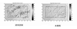
- FIG. 2 shows a processing result obtained by the method of the present invention.
- the prior art shown on the left side of FIG. 2 shows a large variation in both the magnitude and direction of the speed, whereas the present invention shown on the right side of FIG. 2 outputs a more stable solution. I understand.
- the two-dimensional or three-dimensional speed of the observation target is accurately determined from the one-dimensional speed of the observation target along the sensor line-of-sight direction by the weather sensor S. Can be estimated.
- an estimated value that substantially maintains the spatial resolution of the observed value is output, and a local phenomenon directly connected to a disaster can be detected with high accuracy.
- the present invention can be used by the Japan Meteorological Agency, airlines, weather operators, etc. for data processing of observation information of weather sensors that have already been installed or will be installed in the future, and has industrial applicability.
- the present invention can also be applied to data processing software for weather sensor observation information produced by a weather data processing software manufacturer, a weather sensor manufacturer, or the like.
Landscapes
- Engineering & Computer Science (AREA)
- Remote Sensing (AREA)
- Radar, Positioning & Navigation (AREA)
- Environmental & Geological Engineering (AREA)
- Life Sciences & Earth Sciences (AREA)
- Physics & Mathematics (AREA)
- Ecology (AREA)
- Environmental Sciences (AREA)
- Biodiversity & Conservation Biology (AREA)
- Atmospheric Sciences (AREA)
- Computer Networks & Wireless Communication (AREA)
- General Physics & Mathematics (AREA)
- Electromagnetism (AREA)
- Hydrology & Water Resources (AREA)
- Radar Systems Or Details Thereof (AREA)
Abstract
センサ視線方向に沿った観測対象の1次元の速度から、観測対象の2次元または3次元の速度を正確に推定する観測情報処理装置、観測情報処理方法、及び観測情報処理プログラムを提供すること。 直交座標系の各格子点における速度ベクトルの全てを要素として含む第1ベクトルと、極座標系の各格子点における速度ベクトルの第1ベクトルを内包する領域全てを要素として含む第2ベクトルと、センサ視線方向の第1ベクトルを内包する領域全ての速度観測値を要素として含む第3ベクトルとを、座標変換行列および投影行列を用いて関連付けた所定の線型方程式に、線形逆問題解法を適用することにより、気象センサSによって取得したセンサ視線方向に沿った観測対象の1次元の速度から、2次元または3次元の速度を推定する速度推定部30を有する観測情報処理装置10。
Description
本発明は、気象センサによって取得した観測情報を処理する観測情報処理装置、観測情報処理方法、及び観測情報処理プログラムに関する。
気象レーダ等の気象センサは、他の直接観測機器に比して、降水の情報について広範囲を短時間で観測できるという点で有用であり、今日我が国では重要な社会インフラとして用いられている。気象庁では、全国に大型の気象センサを配備し、日本全土の降水情報を常時監視している。また、気象情報がその運用に重要な役割を果たす空港でも、主要な空港には全て空港用ドップラーレーダが設置・運用されている。
一般に気象レーダでは、降水による受信信号から、各地点における受信信号強度、ドップラー速度、及びドップラー速度幅の3値を抽出し、受信信号強度は降水の強さに対する目安となる値、ドップラー速度は風速に対応する値、ドップラー速度幅は風の荒れ具合に対応する値として用いられる。この中で特にドップラー速度は、各地点における速度を気象レーダの視線方向に投影した1次元の値であり、実際の2次元または3次元の速度を推定することは、気象レーダの速度データを活用する上で必須である。
従来、2次元または3次元の速度場を推定する手法として、VVP(Velocity Volume Processing)法(例えば非特許文献1参照)が用いられてきた。この従来のVVP法は、任意の分解体積内において線形速度場を仮定することで2次元または3次元の速度場と視線方向速度場を関連付ける線形問題として定式化を行い、観測された視線方向速度場から最小二乗法を以て2次元または3次元の速度の推定を行うものである。
R. J. Doviak and D. S. Zrnic, "Doppler Radar and Weather Observations" San Diego, CA: Academic, 1993.
R. J. Trapp and C. A. Doswell III (2000), Radar data objective analysis, J. Atmos. Oceanic Technol., vol. 17, 105-120.
南茂夫、「科学計測のためのデータ処理入門」、CQ出版、2002年
V. N. Bringi, and V. Chandrasekar (2001), Polarimetric Doppler Weather Radar:Principles and Applications, chap. 5, 211-293, Cambridge Univ. Press, Cambridge,U.K..
ところが、従来のVVP法では、以下に記載するような問題がある。
すなわち、従来手法では、観測される視線方向速度値に無視できるほど小さな誤差しか含まれない理想的な場合にのみ、優れた2次元または3次元の速度値の推定が可能となる。しかし、一般に、気象レーダの視線方向速度値においては、従来手法にとって無視できない観測誤差が含まれることが多く、その場合、推定値の正確性及び安定性が著しく悪化するという問題があった。
また、従来手法において、観測誤差を含んだ状況にいても推定精度を向上させる有効な方法の一つとして、多くの視線方向を含むよう分解体積を大きく(一般にレーダに対して角度方向30度程度の幅)定義することである。これにより、推定値の安定性が向上するが、一方で空間分解能が悪化し、災害に直結する局所的な現象の検出性が低下する。もう一つは、分解体積内に含まれる複数の視線方向の速度値から、大きな観測誤差が含まれる異常値を検出し、入力から除外することによって、推定値の安定性を向上させることが可能であるが、これも局所現象そのものを異常値として除外する可能性を孕んでおり、検出性を低下させるという問題がある。
そこで、本発明は、これらの問題点を解決するものであり、観測誤差に影響を受けることや、災害に直結する局所現象を除外することなく、センサ視線方向に沿った観測対象の1次元の速度から、観測対象の2次元または3次元の速度を正確に推定する観測情報処理装置、観測情報処理方法、及び観測情報処理プログラムを提供することを目的とするものである。
本請求項1に係る発明は、気象センサによって取得した観測情報を処理する観測情報処理装置であって、所定の線型方程式に線形逆問題解法を適用することにより、前記気象センサによって取得したセンサ視線方向に沿った観測対象の1次元の速度から、2次元または3次元の速度を推定する速度推定部を有し、前記所定の線型方程式は、センサ観測領域内に規定した2次元または3次元の直交座標系の各格子点における2次元または3次元の速度ベクトルの全てを要素として含む第1ベクトルと、前記気象センサの位置を基準とした2次元または3次元の極座標系の各格子点における2次元または3次元の速度ベクトルの前記第1ベクトルを内包する領域全てを要素として含む第2ベクトルと、前記センサ視線方向の前記第1ベクトルを内包する領域全ての速度観測値を要素として含む第3ベクトルとを、前記第1ベクトルと前記第2ベクトルとを関連付ける座標変換行列、および、前記第2ベクトルと前記第3ベクトルとを関連付ける投影行列を用いて関連付けたものであることにより、前記課題を解決するものである。
本請求項2に係る発明は、請求項1に係る発明の構成に加え、前記第1ベクトルは、下記式(1)または下記式(2)で表され、前記第2ベクトルは、下記式(3)または下記式(4)で表され、前記第3ベクトルは、下記式(5)で表され、前記第1ベクトルと前記第2ベクトルとの関係は、下記式(6)で表され、前記第2ベクトルと前記第3ベクトルとの関係は、下記式(7)で表され、前記第1ベクトルと前記第3ベクトルとの関係は、下記式(8)で表されることにより、前記課題を解決するものである。








本請求項3に係る発明は、前記線形逆問題解法は、最小平均二乗誤差法(MMSE)であることにより、前記課題を解決するものである。
本請求項4に係る発明は、気象センサによって取得した観測情報を処理する観測情報処理方法であって、センサ観測領域内に規定した2次元または3次元の直交座標系の各格子点における2次元または3次元の速度ベクトルの全てを要素として含む第1ベクトルと、前記気象センサの位置を基準とした2次元または3次元の極座標系の各格子点における2次元または3次元の速度ベクトルの前記第1ベクトルを内包する領域全てを要素として含む第2ベクトルと、前記センサ視線方向の全ての速度観測値を要素として含む第3ベクトルとを、前記第1ベクトルと前記第2ベクトルとを関連付ける座標変換行列、および、前記第2ベクトルと前記第3ベクトルとを関連付ける投影行列を用いて関連付けた所定の線型方程式に、線形逆問題解法を適用することにより、前記気象センサによって取得したセンサ視線方向に沿った観測対象の1次元の速度から、2次元または3次元の速度を推定することにより、前記課題を解決するものである。
本請求項5に係る発明は、気象センサによって取得した観測情報を処理する観測情報処理プログラムであって、センサ観測領域内に規定した2次元または3次元の直交座標系の各格子点における2次元または3次元の速度ベクトルの全てを要素として含む第1ベクトルと、前記気象センサの位置を基準とした2次元または3次元の極座標系の各格子点における2次元または3次元の速度ベクトルの前記第1ベクトルを内包する領域全てを要素として含む第2ベクトルと、前記センサ視線方向の全ての速度観測値を要素として含む第3ベクトルとを、前記第1ベクトルと前記第2ベクトルとを関連付ける座標変換行列、および、前記第2ベクトルと前記第3ベクトルとを関連付ける投影行列を用いて、関連付けた所定の線型方程式に、線形逆問題解法を適用することにより、前記気象センサによって取得したセンサ視線方向に沿った観測対象の1次元の速度から、2次元または3次元の速度を推定する手順をコンピュータに実行させることにより、前記課題を解決するものである。
本請求項4に係る発明は、気象センサによって取得した観測情報を処理する観測情報処理方法であって、センサ観測領域内に規定した2次元または3次元の直交座標系の各格子点における2次元または3次元の速度ベクトルの全てを要素として含む第1ベクトルと、前記気象センサの位置を基準とした2次元または3次元の極座標系の各格子点における2次元または3次元の速度ベクトルの前記第1ベクトルを内包する領域全てを要素として含む第2ベクトルと、前記センサ視線方向の全ての速度観測値を要素として含む第3ベクトルとを、前記第1ベクトルと前記第2ベクトルとを関連付ける座標変換行列、および、前記第2ベクトルと前記第3ベクトルとを関連付ける投影行列を用いて関連付けた所定の線型方程式に、線形逆問題解法を適用することにより、前記気象センサによって取得したセンサ視線方向に沿った観測対象の1次元の速度から、2次元または3次元の速度を推定することにより、前記課題を解決するものである。
本請求項5に係る発明は、気象センサによって取得した観測情報を処理する観測情報処理プログラムであって、センサ観測領域内に規定した2次元または3次元の直交座標系の各格子点における2次元または3次元の速度ベクトルの全てを要素として含む第1ベクトルと、前記気象センサの位置を基準とした2次元または3次元の極座標系の各格子点における2次元または3次元の速度ベクトルの前記第1ベクトルを内包する領域全てを要素として含む第2ベクトルと、前記センサ視線方向の全ての速度観測値を要素として含む第3ベクトルとを、前記第1ベクトルと前記第2ベクトルとを関連付ける座標変換行列、および、前記第2ベクトルと前記第3ベクトルとを関連付ける投影行列を用いて、関連付けた所定の線型方程式に、線形逆問題解法を適用することにより、前記気象センサによって取得したセンサ視線方向に沿った観測対象の1次元の速度から、2次元または3次元の速度を推定する手順をコンピュータに実行させることにより、前記課題を解決するものである。
本請求項1、4、5に係る発明によれば、センサ観測領域内に規定した2次元または3次元の直交座標系の各格子点における2次元または3次元の速度ベクトルの全てを要素として含む第1ベクトルと、気象センサの位置を基準とした2次元または3次元の極座標系の各格子点における2次元または3次元の速度ベクトルの前記第1ベクトルを内包する領域全てを要素として含む第2ベクトルと、センサ視線方向の全ての速度観測値を要素として含む第3ベクトルとを、第1ベクトルと第2ベクトルとを関連付ける座標変換行列、および、第2ベクトルと第3ベクトルとを関連付ける投影行列を用いて関連付けた所定の線型方程式に、線形逆問題解法を適用することにより、気象センサによるセンサ視線方向に沿った観測対象の1次元の速度から、観測対象の2次元または3次元の速度を正確に推定できる。また、観測値の空間分解能をほぼ維持した推定値を出力し、災害に直結する局所現象を高精度に検出することができる。
本請求項2に係る発明によれば、災害に直結する局所現象の検出性を損なうことなく、観測対象の2次元または3次元の速度を安定して推定することができる。
本請求項3に係る発明によれば、線形逆問題解法として最小平均二乗誤差法(MMSE)を用いることにより、より高精度な観測対象の2次元または3次元の速度の推定が可能となる。
本請求項3に係る発明によれば、線形逆問題解法として最小平均二乗誤差法(MMSE)を用いることにより、より高精度な観測対象の2次元または3次元の速度の推定が可能となる。
10 ・・・ 観測情報処理装置
20 ・・・ 制御部
30 ・・・ 速度推定部
40 ・・・ 送受信部
20 ・・・ 制御部
30 ・・・ 速度推定部
40 ・・・ 送受信部
本発明は、気象センサによって取得した観測情報を処理する観測情報処理装置であって、所定の線型方程式に線形逆問題解法を適用することにより、気象センサによって取得したセンサ視線方向に沿った観測対象の1次元の速度から、2次元または3次元の速度を推定する速度推定部を有し、所定の線型方程式は、センサ観測領域内に規定した2次元または3次元の直交座標系の各格子点における2次元または3次元の速度ベクトルの全てを要素として含む第1ベクトルと、気象センサの位置を基準とした2次元または3次元の極座標系の各格子点における2次元または3次元の速度ベクトルの第1ベクトルを内包する領域全てを要素として含む第2ベクトルと、センサ視線方向の第1ベクトルを内包する領域全ての速度観測値を要素として含む第3ベクトルとを、第1ベクトルと第2ベクトルとを関連付ける座標変換行列、および、第2ベクトルと第3ベクトルとを関連付ける投影行列を用いて関連付けたものであり、観測誤差に影響を受けることや、災害に直結する局所現象を除外することなく、センサ視線方向に沿った観測対象の1次元の速度から、観測対象の2次元または3次元の速度を正確に推定するものであれば、その具体的な構成は如何なるものでもよい。
例えば、本発明における気象センサとしては、気象レーダ、気象ライダ、ソーダ等の体積スキャンが可能な速度計測リモートセンサ一般を用いることができる。また、後述する実施形態では、1つの気象センサが設置された場合を説明するが、本発明は、複数の気象センサを設置した場合にも適用することができる。
また、後述する実施形態では、観測情報処理装置によって生成される情報が、航空機運航における各種判断に関する支援情報であるものとして説明するが、生成した情報の用途はこれに限定されない。
また、本発明で用いる線形逆問題解法については、最小平均二乗誤差法(MMSE、Minimum Mean Square Error)、最小二乗法(LS、Least Square)、正則化最小二乗法(NLS、Normalized Least Square)、特異値分解最小平均二乗誤差法(SVD-MMSE、Singular Value Decomposition Minimum Mean Square Error)等の如何なるものでもよいが、最小平均二乗誤差法(MMSE)を用いた場合、より高精度な観測対象の2次元または3次元の速度の推定が可能となるため、好ましい。
また、後述する実施形態では、観測情報処理装置によって生成される情報が、航空機運航における各種判断に関する支援情報であるものとして説明するが、生成した情報の用途はこれに限定されない。
また、本発明で用いる線形逆問題解法については、最小平均二乗誤差法(MMSE、Minimum Mean Square Error)、最小二乗法(LS、Least Square)、正則化最小二乗法(NLS、Normalized Least Square)、特異値分解最小平均二乗誤差法(SVD-MMSE、Singular Value Decomposition Minimum Mean Square Error)等の如何なるものでもよいが、最小平均二乗誤差法(MMSE)を用いた場合、より高精度な観測対象の2次元または3次元の速度の推定が可能となるため、好ましい。
以下に、本発明の一実施形態である観測情報処理装置10について、図1、2に基づいて説明する。
観測情報処理装置10は、気象レーダ等の気象センサSによって取得した、ドップラー速度を含む観測情報をデータ処理し、各種情報を生成するものであり、特に、航空機運航における各種判断に関する支援情報を生成するものである。観測情報処理装置10は、制御部20、気象センサSとの間で情報を送受信する送受信部40、記憶部、入力部、出力部、補助記憶装置等を備え、制御部20を記憶部に展開されたソフトウェアに従って動作させることにより、後述する各部を実現する。制御部20は、CPU等で構成され、記憶部は、ROM、RAM等で構成されている。
制御部20は、図1に示すように、気象センサSによって取得したセンサ視線方向に沿った観測対象の1次元の速度から2次元または3次元の速度を推定する速度推定部30を有している。
以下に、速度推定部30による処理の具体的内容について説明する。なお、説明を簡単にするため、以下においては、気象センサSが仰角0度のベーススキャン(全方位スキャン)の場合を仮定し、まずは水平2次元のみについて考える。

まず、推定すべき速度場である2次元速度場ベクトルVc(任意の格子点長さを有する直交座標系上の全格子点の2次元速度を要素として含むベクトル、第1ベクトル)と、気象センサS固有の極座標系における2次元速度場ベクトルVp(気象センサSで定義される極座標系上の全格子点の2次元速度を要素として含むベクトル、第2ベクトル)とは、以下の式(10)に示すように関連付けられる。

式(10)中、Tは座標変換行列であり、最近接法、線型変換法、ガウシアン重み付け平均法等、一般的なものを使用する(非特許文献2を参照)。
また、2次元速度場ベクトルVcは、以下の式(11)で表される。

式(11)中、Vx(n)及びVy(n)は、それぞれ、直交座標系上の第n格子点におけるx及びy方向速度である。nは、定義された直交座標系上の格子点の数である。
また、2次元速度場ベクトルVpは、以下の式(12)で表される。

式(12)中、Vx(m)及びVy(m)は、それぞれ、センサ極座標系上の第m格子点におけるx及びy方向速度である。mは、気象センサS固有の極座標系の格子点の数である。
次に、センサ極座標上の2次元速度場ベクトルVpと、視線方向速度の全観測値を要素として含む観測値ベクトルVr(第3ベクトル)は、以下の式(13)で示すように関連付けられる。

式(13)中、Pはセンサ極座標上の各格子点における2次元速度と視線方向速度を関連付ける投影を全て含んだ、投影行列である。
また、観測値ベクトルVrは、以下の式(14)で表される。

式(14)中、Vr(m)は、センサ極座標系上の第m格子点における視線方向速度である。
そして、上記の式(10)及び式(13)より、以下の式(15)に示すように、線型方程式の定式化が可能である。

なお、式(11)、式(12)、及び式(14)から理解できるように、必ずしもセンサ観測領域全体を定義する必要はなく、任意に定義した一定の領域において定式化することも可能である。
つぎに、上記の式(15)で表される線型方程式に対して、最小平均二乗誤差法(MMSE、Minimum Mean Square Error)を用いた解法を適用する(非特許文献3を参照)。導出される解^Vcを以下の式(16)に示す。

式(16)中、σVrは観測される視線方向速度の観測誤差における標準偏差、σVcは推定される2次元速度場ベクトルにおける標準偏差である。
ここでも、気象センサSは仰角0度のベーススキャン(全方位各スキャン)を仮定し、水平2次元のみについて考え、具体例を示す。
観測される視線方向速度が有する確率密度関数は、非特許文献4にて示され、標準偏差σVrが導出される。また、推定される2次元速度場における標準偏差σVcは、非特許文献1に示されるように分解体積の大きさに比例して決定することができる。以上の2値に加え、観測された視線方向速度ベクトル(式(14))を式(16)に代入することにより、推定値が算出される。
なお、上記では、2次元の速度を算出する場合を説明したが、3次元の速度を算出する場合には、2次元速度場ベクトルVc(第1ベクトル)は以下の式(17)で表され、また、2次元速度場ベクトルVp(第2ベクトル)は以下の式(18)で表される。

式(17)中、Vx(n)、Vy(n)、及びVz(n)は、それぞれ、直交座標系上の第n格子点におけるx、y、及びz方向速度である。nは、定義されたカテシアン座標系上の格子点の数である。

式(18)中、Vx(m)、Vy(m)、及びVz(m)は、それぞれ、直交座標系上の第n格子点におけるx、y、及びz方向速度である。mは、定義された直交座標系上の格子点の数である。
図2に本発明の手法による処理結果を示す。図2の左側に示す従来技術では、速度の大きさおよび向きの両方に大きなバラツキが見られるのに対して、図2の右側に示す本発明では、より安定した解を出力していることが分かる。
このようにして得られた本実施形態の観測情報処理装置10では、気象センサSによるセンサ視線方向に沿った観測対象の1次元の速度から、観測対象の2次元または3次元の速度を正確に推定できる。また、観測値の空間分解能をほぼ維持した推定値を出力し、災害に直結する局所現象を高精度に検出することができる。
本発明は、気象庁、航空会社、気象業務業者等が、既に設置もしくは今後設置する気象センサの観測情報のデータ処理に利用することができ、産業上の利用可能性を有する。また、本発明は、気象データ処理のソフトウェアメーカ、気象センサメーカ等が制作する気象センサの観測情報のデータ処理ソフトウェアにも適用することができる。
Claims (5)
- 気象センサによって取得した観測情報を処理する観測情報処理装置であって、
所定の線型方程式に線形逆問題解法を適用することにより、前記気象センサによって取得したセンサ視線方向に沿った観測対象の1次元の速度から、2次元または3次元の速度を推定する速度推定部を有し、
前記所定の線型方程式は、
センサ観測領域内に規定した2次元または3次元の直交座標系の各格子点における2次元または3次元の速度ベクトルの全てを要素として含む第1ベクトルと、
前記気象センサの位置を基準とした2次元または3次元の極座標系の各格子点における2次元または3次元の速度ベクトルの前記第1ベクトルを内包する領域全てを要素として含む第2ベクトルと、
前記センサ視線方向の前記第1ベクトルを内包する領域全ての速度観測値を要素として含む第3ベクトルとを、
前記第1ベクトルと前記第2ベクトルとを関連付ける座標変換行列、および、前記第2ベクトルと前記第3ベクトルとを関連付ける投影行列を用いて関連付けたものであることを特徴とする観測情報処理装置。 - 前記第1ベクトルは、下記式(1)または下記式(2)で表され、
前記第2ベクトルは、下記式(3)または下記式(4)で表され、
前記第3ベクトルは、下記式(5)で表され、
前記第1ベクトルと前記第2ベクトルとの関係は、下記式(6)で表され、
前記第2ベクトルと前記第3ベクトルとの関係は、下記式(7)で表され、
前記第1ベクトルと前記第3ベクトルとの関係は、下記式(8)で表されることを特徴とする請求項1に記載の観測情報処理装置。








- 前記線形逆問題解法は、最小平均二乗誤差法(MMSE)であることを特徴とする請求項1または請求項2に記載の観測情報処理装置。
- 気象センサによって取得した観測情報を処理する観測情報処理方法であって、
センサ観測領域内に規定した2次元または3次元の直交座標系の各格子点における2次元または3次元の速度ベクトルの全てを要素として含む第1ベクトルと、前記気象センサの位置を基準とした2次元または3次元の極座標系の各格子点における2次元または3次元の速度ベクトルの前記第1ベクトルを内包する領域全てを要素として含む第2ベクトルと、前記センサ視線方向の前記第1ベクトルを内包する領域全ての速度観測値を要素として含む第3ベクトルとを、前記第1ベクトルと前記第2ベクトルとを関連付ける座標変換行列、および、前記第2ベクトルと前記第3ベクトルとを関連付ける投影行列を用いて関連付けた所定の線型方程式に、線形逆問題解法を適用することにより、前記気象センサによって取得したセンサ視線方向に沿った観測対象の1次元の速度から、2次元または3次元の速度を推定することを特徴とする観測情報処理方法。 - 気象センサによって取得した観測情報を処理する観測情報処理プログラムであって、
センサ観測領域内に規定した2次元または3次元の直交座標系の各格子点における2次元または3次元の速度ベクトルの全てを要素として含む第1ベクトルと、前記気象センサの位置を基準とした2次元または3次元の極座標系の各格子点における2次元または3次元の速度ベクトルの前記第1ベクトルを内包する領域全てを要素として含む第2ベクトルと、前記センサ視線方向の前記第1ベクトルを内包する領域全ての速度観測値を要素として含む第3ベクトルとを、前記第1ベクトルと前記第2ベクトルとを関連付ける座標変換行列、および、前記第2ベクトルと前記第3ベクトルとを関連付ける投影行列を用いて、関連付けた所定の線型方程式に、線形逆問題解法を適用することにより、前記気象センサによって取得したセンサ視線方向に沿った観測対象の1次元の速度から、2次元または3次元の速度を推定する手順を
コンピュータに実行させることを特徴とする観測情報処理プログラム。
Applications Claiming Priority (2)
| Application Number | Priority Date | Filing Date | Title |
|---|---|---|---|
| JP2013-257642 | 2013-12-13 | ||
| JP2013257642A JP2015114249A (ja) | 2013-12-13 | 2013-12-13 | 観測情報処理装置、観測情報処理方法、及び観測情報処理プログラム |
Publications (1)
| Publication Number | Publication Date |
|---|---|
| WO2015087589A1 true WO2015087589A1 (ja) | 2015-06-18 |
Family
ID=53370908
Family Applications (1)
| Application Number | Title | Priority Date | Filing Date |
|---|---|---|---|
| PCT/JP2014/073441 Ceased WO2015087589A1 (ja) | 2013-12-13 | 2014-09-05 | 観測情報処理装置、観測情報処理方法、及び観測情報処理プログラム |
Country Status (2)
| Country | Link |
|---|---|
| JP (1) | JP2015114249A (ja) |
| WO (1) | WO2015087589A1 (ja) |
Cited By (2)
| Publication number | Priority date | Publication date | Assignee | Title |
|---|---|---|---|---|
| CN106896818A (zh) * | 2016-12-26 | 2017-06-27 | 中国科学院长春光学精密机械与物理研究所 | 空间对地观测仪器的自动避日方法 |
| US11276376B2 (en) * | 2019-06-14 | 2022-03-15 | Honeywell International Inc. | System and method for 3D display of dynamic objects on synthetic vision system in cockpit display system |
Citations (2)
| Publication number | Priority date | Publication date | Assignee | Title |
|---|---|---|---|---|
| JP2004212274A (ja) * | 2003-01-07 | 2004-07-29 | Mitsubishi Electric Corp | 風速ベクトル計測装置及び風速ベクトル計測方法 |
| JP2010096593A (ja) * | 2008-10-15 | 2010-04-30 | Japan Weather Association | 風予測装置及びプログラム |
-
2013
- 2013-12-13 JP JP2013257642A patent/JP2015114249A/ja active Pending
-
2014
- 2014-09-05 WO PCT/JP2014/073441 patent/WO2015087589A1/ja not_active Ceased
Patent Citations (2)
| Publication number | Priority date | Publication date | Assignee | Title |
|---|---|---|---|---|
| JP2004212274A (ja) * | 2003-01-07 | 2004-07-29 | Mitsubishi Electric Corp | 風速ベクトル計測装置及び風速ベクトル計測方法 |
| JP2010096593A (ja) * | 2008-10-15 | 2010-04-30 | Japan Weather Association | 風予測装置及びプログラム |
Cited By (2)
| Publication number | Priority date | Publication date | Assignee | Title |
|---|---|---|---|---|
| CN106896818A (zh) * | 2016-12-26 | 2017-06-27 | 中国科学院长春光学精密机械与物理研究所 | 空间对地观测仪器的自动避日方法 |
| US11276376B2 (en) * | 2019-06-14 | 2022-03-15 | Honeywell International Inc. | System and method for 3D display of dynamic objects on synthetic vision system in cockpit display system |
Also Published As
| Publication number | Publication date |
|---|---|
| JP2015114249A (ja) | 2015-06-22 |
Similar Documents
| Publication | Publication Date | Title |
|---|---|---|
| Fresno et al. | Survey on the performance of source localization algorithms | |
| EP3693759B1 (en) | System and method for tracking motion of target in indoor environment | |
| CN109839624A (zh) | 一种多激光雷达位置标定方法及装置 | |
| CN109313258A (zh) | 用于车辆环境检测系统的增强的物体检测和运动状态估计 | |
| Taghavi et al. | Multisensor-multitarget bearing-only sensor registration | |
| CN105044667B (zh) | 一种运动目标的双星跟踪方法、装置和系统 | |
| JP6996729B2 (ja) | 電磁界データ取得システム、飛行体、端末装置、および、プログラム | |
| CN103679693A (zh) | 一种多相机单视图标定装置及其标定方法 | |
| CN106093951A (zh) | 基于超声波传感器阵列的物体跟踪方法 | |
| JP2017096813A (ja) | キャリブレーション装置、キャリブレーション方法およびキャリブレーションプログラム | |
| Mei et al. | Trajectory optimization of autonomous surface vehicles with outliers for underwater target localization | |
| Lee et al. | Nontarget-based measurement of 6-DOF structural displacement using combined RGB color and depth information | |
| Chang et al. | Versatile multi-lidar accurate self-calibration system based on pose graph optimization | |
| CN105372671A (zh) | 一种基于无人机的电力线三维重建系统 | |
| JP6210845B2 (ja) | 目標追尾装置及び目標追尾方法 | |
| WO2015087589A1 (ja) | 観測情報処理装置、観測情報処理方法、及び観測情報処理プログラム | |
| CN112578363B (zh) | 激光雷达运动轨迹获取方法及装置、介质 | |
| CN112611371B (zh) | 一种多场景二维地图的位姿转换方法及系统 | |
| Bolopion et al. | Vision-based haptic feedback for remote micromanipulation in–SEM environment | |
| CN114694107B (zh) | 一种图像处理方法、装置、电子设备和存储介质 | |
| JP3904215B2 (ja) | センサ管理装置及びセンサ管理方法 | |
| CN104698444B (zh) | 确定阵元位置误差对阵列天线三维成像质量影响的方法 | |
| Kowalski et al. | CRLB for multi-sensor rotational bias estimation for passive sensors without target state estimation | |
| CN114742141A (zh) | 基于icp点云的多源信息数据融合研判方法 | |
| Liu-Henke et al. | Function development for self-localization through sensor data fusion for autonomous vehicles |
Legal Events
| Date | Code | Title | Description |
|---|---|---|---|
| 121 | Ep: the epo has been informed by wipo that ep was designated in this application |
Ref document number: 14868733 Country of ref document: EP Kind code of ref document: A1 |
|
| NENP | Non-entry into the national phase |
Ref country code: DE |
|
| 122 | Ep: pct application non-entry in european phase |
Ref document number: 14868733 Country of ref document: EP Kind code of ref document: A1 |