WO2015083224A1 - 通信網制御方法、通信網制御プログラム、システム、および記録媒体 - Google Patents
通信網制御方法、通信網制御プログラム、システム、および記録媒体 Download PDFInfo
- Publication number
- WO2015083224A1 WO2015083224A1 PCT/JP2013/082396 JP2013082396W WO2015083224A1 WO 2015083224 A1 WO2015083224 A1 WO 2015083224A1 JP 2013082396 W JP2013082396 W JP 2013082396W WO 2015083224 A1 WO2015083224 A1 WO 2015083224A1
- Authority
- WO
- WIPO (PCT)
- Prior art keywords
- node
- communication
- nodes
- divided
- area
- Prior art date
- Legal status (The legal status is an assumption and is not a legal conclusion. Google has not performed a legal analysis and makes no representation as to the accuracy of the status listed.)
- Ceased
Links
Images










Classifications
-
- H—ELECTRICITY
- H04—ELECTRIC COMMUNICATION TECHNIQUE
- H04W—WIRELESS COMMUNICATION NETWORKS
- H04W24/00—Supervisory, monitoring or testing arrangements
- H04W24/10—Scheduling measurement reports ; Arrangements for measurement reports
-
- H—ELECTRICITY
- H04—ELECTRIC COMMUNICATION TECHNIQUE
- H04W—WIRELESS COMMUNICATION NETWORKS
- H04W16/00—Network planning, e.g. coverage or traffic planning tools; Network deployment, e.g. resource partitioning or cells structures
- H04W16/18—Network planning tools
-
- H—ELECTRICITY
- H04—ELECTRIC COMMUNICATION TECHNIQUE
- H04W—WIRELESS COMMUNICATION NETWORKS
- H04W16/00—Network planning, e.g. coverage or traffic planning tools; Network deployment, e.g. resource partitioning or cells structures
-
- H—ELECTRICITY
- H04—ELECTRIC COMMUNICATION TECHNIQUE
- H04W—WIRELESS COMMUNICATION NETWORKS
- H04W48/00—Access restriction; Network selection; Access point selection
- H04W48/16—Discovering, processing access restriction or access information
-
- H—ELECTRICITY
- H04—ELECTRIC COMMUNICATION TECHNIQUE
- H04W—WIRELESS COMMUNICATION NETWORKS
- H04W84/00—Network topologies
- H04W84/18—Self-organising networks, e.g. ad-hoc networks or sensor networks
Definitions
- a technique for constructing a network with a plurality of communication nodes connectable by radio is known. For example, when sending a packet from a transmission destination node to a transmission source node through a predetermined communication path, among the intermediate nodes on the predetermined communication path, the node having the smallest hop count from the transmission destination node and the maximum node A technique for setting the respective communication paths is known (for example, refer to Patent Document 1 below).
- Patent Document 1 there is a technique in which there are a plurality of wirelessly connectable nodes, detecting nearby nodes, forming clusters, and connecting neighboring clusters to construct a network (for example, the following patents) Reference 2).
- An object of one aspect of the present invention is to provide a communication network control method, a communication network control program, a system, and a recording medium that can improve network reliability.
- the present invention provides a sensor measurement region included in a communication node for each of some communication nodes included in a communication network among a plurality of communication nodes installed in an arrangement region. Measurement area information to be obtained, division area information indicating a plurality of division areas obtained by dividing the arrangement area is obtained, and for each of the plurality of division areas indicated by the obtained division area information, Among them, a value corresponding to the number of communication nodes in which at least a part of the divided area is included in the measurement area indicated by the acquired measurement area information is derived, and according to the value derived for each of the plurality of divided areas A communication network control method, a communication network control program, a system, and a recording medium for performing control to change a communication node included in the communication network are proposed.
- FIG. 1 is an explanatory diagram showing an operation example by the monitoring server according to the present invention.
- FIG. 2 is an explanatory diagram showing an example of bias of the redundant node rnd.
- FIG. 3 is an explanatory diagram showing an example of use of the system according to the present invention.
- FIG. 4 is a block diagram illustrating a hardware configuration example of the sensor node 101.
- FIG. 5 is a block diagram illustrating a hardware configuration example of the monitoring server 100.
- FIG. 6 is an explanatory diagram illustrating a basic data configuration example of a signal.
- FIG. 7 is an explanatory diagram (part 1) of a data configuration example of each signal.
- FIG. 8 is an explanatory diagram (part 2) of a data configuration example of each signal.
- FIG. 1 is an explanatory diagram showing an operation example by the monitoring server according to the present invention.
- FIG. 2 is an explanatory diagram showing an example of bias of the redundant node rnd.
- FIG. 3 is an explanatory diagram showing
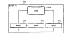
- FIG. 9 is a block diagram illustrating a functional configuration example of the monitoring server 100.
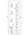
- FIG. 10 is an explanatory diagram illustrating an example of the contents stored in the storage unit 904 of the monitoring server 100.
- FIG. 11 is a block diagram illustrating a functional configuration example of the sensor node 101.
- FIG. 12 is an explanatory diagram illustrating an example of the contents stored in the storage unit of the sensor node 101.
- FIG. 13 is an explanatory diagram showing an example of an operation sequence for provisional network SNET construction.
- FIG. 14 is an explanatory diagram illustrating an example of a node with less overlap.
- FIG. 15 is an explanatory diagram illustrating an example of an operation sequence for position measurement.
- FIG. 16 is an explanatory diagram showing an example of distribution density analysis.
- FIG. 10 is an explanatory diagram illustrating an example of the contents stored in the storage unit 904 of the monitoring server 100.
- FIG. 11 is a block diagram illustrating a functional configuration example of the sensor node 101.
- FIG. 23 is a flowchart illustrating an example of a density difference elimination processing procedure by the monitoring server 100.
- FIG. 24 is a flowchart illustrating an example of a thinning process procedure by the monitoring server 100.
- FIG. 25 is a flowchart illustrating an example of a node addition processing procedure performed by the monitoring server 100.
- FIG. 26 is a flowchart (part 1) illustrating an example of a processing procedure performed by the sensor node 101.
- FIG. 27 is a flowchart (part 2) illustrating an example of a processing procedure performed by the sensor node 101.
- FIG. 28 is a flowchart (part 3) illustrating an example of a processing procedure performed by the sensor node 101.
- FIG. 29 is a flowchart (part 4) illustrating an example of a processing procedure performed by the sensor node 101.
- FIG. 1 is an explanatory view showing an operation example by the monitoring server according to the present invention.
- the monitoring server 100 is a computer that controls the construction of the network SNET among the plurality of sensor nodes 101 arranged in the arrangement area area, and is a communication device that can communicate with the plurality of sensor nodes 101.
- the sensor node 101 is a communication node having a sensor and a small wireless communication circuit.
- a communication network is formed by the sensor nodes 101 communicating with each other.
- the communication network is called a network SNET.
- the sensor node 101 included in the network SNET is also referred to as a connection node cnd.
- the sensor nodes 101 other than the connection node cnd are also referred to as redundant nodes rnd.
- the network SNET is constructed by the monitoring server 100, but the network SNET has been constructed here.
- the connection nodes cnd are connected by lines, but as described above, the connection nodes cnd are actually connected by wireless communication.
- connection node cnd performs a sensor measurement operation, a data transmission operation obtained by the measurement operation, a data transfer operation from another connection node cnd, and the like, while the redundant node rnd performs a measurement operation. No data transfer operation is performed. Therefore, the redundancy node rnd has a lower degree of aging deterioration than the connection node cnd. For example, when there is a connection node cnd that has been operating for a long time and has failed due to aging degradation, etc., if a redundant node rnd around the failed connection node cnd is newly added to the network SNET, the placement area are The measuring operation can be performed. Therefore, the reliability of the system can be improved.
- the number of connection nodes cnd of the network SNET that includes at least a part of the divided area a in the measurement area sa is analyzed.
- the connection node cnd is changed. Thereby, the distribution of the redundant nodes rnd can be made uniform, and the reliability can be improved.
- the monitoring server 100 acquires, for each of the connection nodes cnd included in the network SNET, measurement area information 103 indicating the sensor measurement area sa of the communication node.
- the measurement area sa-1 of the sensor node 101-1 is the measurement area sa-1.
- the measurement area sa is represented by the position of the sensor node 101 and the measurable distance of the sensor that the sensor node 101 has.
- the position of the sensor node 101 may be a latitude or longitude, or may be a relative position in the arrangement area area.
- the relative position in the arrangement area area is, for example, coordinates based on an axis defined on a simulation space that simulates the arrangement area area. More specifically, as shown in FIG.
- the monitoring server 100 transmits a signal instructing measurement of the position to the sensor node 101 when constructing the temporary network SNET, so that each sensor serves as a response signal to the signal.
- the position of the node 101 is acquired.
- the signal is transmitted from the transmission destination to the transmission source by relay transfer using multi-hop communication.
- the monitoring server 100 acquires divided area information 102 indicating a plurality of divided areas a obtained by dividing the arrangement area area.
- the monitoring server 100 does not physically divide the arrangement area area.
- the monitoring server 100 acquires the divided area information 102 by dividing the arrangement area area into a plurality of divided areas a in a simulation space that simulates the arrangement area area, and generating the divided area information 102 indicating the divided area a.
- the divided area information 102 may be represented by latitude, longitude, or the like, or may be coordinates based on an axis defined on the simulation space.
- the monitoring server 100 divides the arrangement area area according to a predetermined size.
- the predetermined size is determined in advance by the developer. As the predetermined size is smaller, the density described later can be specified in more detail.
- the arrangement area area is divided into 25 divided areas a1 to a25. In FIG. 1, a part of reference numerals a1 to a25 are omitted.
- the monitoring server 100 includes at least a part of the divided area a in the measurement area sa indicated by the acquired measurement area information 103 among the connection nodes cnd.
- a value corresponding to the number of connection nodes cnd to be obtained is derived.
- the derived value is also referred to as density.
- the distribution density of the arrangement area area can be specified.
- the density of the divided area a22 is the lowest, and the density of the divided area a19 is the highest.
- the number of connection nodes cnd itself in which at least a part of the divided area a is included in the measurement area sa is the density, but the monitoring server 100 is based on the degree of overlap between the measurement area sa and the divided area a. The amount of increase for increasing the density may be changed.
- the monitoring server 100 performs control to change the communication node included in the network SNET according to the density derived for each of the plurality of divided regions a. For example, for the divided region a having a low density, there is a high possibility that the number of redundant nodes rnd is large. In other words, there is a high possibility that the number of connection nodes cnd is small for the divided region a having a low density. For this reason, there is a high possibility that measurement of the current divided region a is not performed.
- joining the network SNET is also referred to as connecting to the network SNET.
- the monitoring server 100 transmits at least a part of the divided area a in which the signal instructing connection to the network SNET is selected to the redundant node rnd included in the sensor measurement area sa.
- the redundant node rnd of the transmission destination receives the signal, so that the redundant node rnd can be added to the network SNET. Details of which redundant node rnd is added will be described later.
- the divided area a22 is the divided area having the lowest density. Therefore, the sensor node 101-3 is added to the network SNET.
- the monitoring server 100 selects one of the connection nodes cnd from the connection node cnd that includes at least a part of the divided area a selected based on the derived density among the plurality of divided areas a in the measurement area sa. Are excluded from the network SNET.
- the selected divided area a may be the divided area a having the largest derived density among the divided areas a, or may be the divided area a having a density greater than the threshold, It may be a divided area a that is larger than the average density by a specific value or more.
- the threshold value and specific value are values determined by the developer.
- disconnecting from the network SNET is also referred to as disconnecting from the network SNET.
- the monitoring server 100 transmits a signal instructing disconnection from the network SNET to one of the connection nodes cnd.
- the connection node cnd receives the signal, the connection node cnd is disconnected from the network SNET and becomes a redundant node rnd. Details of which connection node cnd is to be disconnected will be described later.
- the divided area a19 is the divided area with the highest density. Therefore, the sensor node 101-2 is excluded from the network SNET.
- the number of connection nodes cnd is determined as a specified number, and connection processing to the network SNET and disconnection processing from the network SNET are performed so that the number of connection nodes cnd does not exceed the specified number.
- connection processing to the network SNET and disconnection processing from the network SNET are performed so that the number of connection nodes cnd does not exceed the specified number.
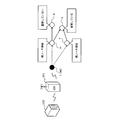
- FIG. 2 is an explanatory diagram showing a bias example of the redundant node rnd.
- FIG. 2A shows an example in which the connection nodes cnd are evenly distributed in the arrangement area area.
- FIG. 2B shows an example in which the connection nodes cnd are not evenly distributed in the arrangement area area.
- the area where the redundant nodes rnd are arranged in the arrangement area area cannot be measured by the sensor.
- the redundant node rnd is small and the redundancy in which the connection node cnd is arranged is replaced when the connection node cnd fails.
- FIG. 3 is an explanatory diagram showing an example of use of the system according to the present invention.
- the system 300 is a sensor network system in which sensor nodes 101 can communicate with each other to form a network SNET and collect sensor data.
- the system 300 includes a plurality of sensor nodes 101 and a monitoring server 100.
- a plurality of sensor nodes 101 are provided in an arrangement area area such as a slope, and the collapse of the slope is monitored by sensors included in the sensor node 101.
- the plurality of sensor nodes 101 may be provided in an arrangement area area filled with a substance such as concrete such as a farm or a building, soil, water, or air.
- the sensor included in the sensor node 101 may measure, for example, temperature, moisture content, vibration, and the like.
- the management server wirelessly communicates with the plurality of sensor nodes 101 via, for example, the gateway 301 and the aggregator ag.
- the aggregator ag may be, for example, the sensor node 101 included in the plurality of sensor nodes 101. In the example of FIG. 3, the aggregator ag is the sensor node 101-1.
- the gateway 301 transmits a signal from the monitoring server 100 to the aggregator ag and transmits a signal from the aggregator ag to the monitoring server 100.
- a very small number of sensor nodes 101 out of a plurality of sensor nodes 101 may be capable of measuring positions by their own sensors such as GPS, or position information may be obtained by a developer of system 300. It may be registered.
- the monitoring server 100 may measure the position of the connection node cnd based on position information indicating the positions of some of these sensor nodes 101. A detailed measurement example will be described later.
- the monitoring server 100 also refers to the sensor node 101 specifying the position as a reference point node.
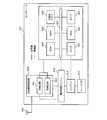
- FIG. 4 is a block diagram illustrating a hardware configuration example of the sensor node 101.
- the sensor node 101 includes a sensor 401, an MCU (Micro Control Unit) 402, a timer 403, a ROM (Read Only Memory) 404, a RAM (Random Access Memory) 405, and a nonvolatile memory 406.
- the sensor node 101 includes a short-range wireless circuit 408, an antenna 409, a power management unit 410, a battery 411, a harvester 412, and the like.
- the sensor node 101 also has an internal bus 407 that connects the sensor 401, MCU 402, timer 403, ROM 404, RAM 405, and nonvolatile memory 406. Further, in FIG. 4, a dotted line indicates a power supply line, and a solid line indicates a signal line.
- Sensor 401 detects a predetermined amount of displacement at the installation location.
- the sensor 401 for example, a piezoelectric element that detects a pressure at an installation location, an element that detects temperature, a photoelectric element that detects light, or the like can be used.
- the area that can be measured by the sensor 401 is the measurement area sa.
- An area within a predetermined distance from the position of the sensor node 101 is a measurement area sa. The predetermined distance varies depending on the type and performance of the sensor 401.
- the MCU 402 is a control unit that performs overall control and data processing of the sensor node 101 by loading a program stored in the ROM 404 into the RAM 405 and executing the program, for example.
- the MCU 402 processes data detected by the sensor 401.
- the timer 403 counts the time set by the MCU 402 or the like. In the present embodiment, for example, the timer 403 counts a sensing interval for sensing by the sensor 401 spontaneously. For example, the timer 403 counts a predetermined period during which the short-range wireless circuit 408 is stopped in the second embodiment described later.
- the ROM 404 is a storage unit that stores programs executed by the MCU 402.
- the RAM 405 is a storage unit that stores temporary data for processing in the MCU 402.
- the nonvolatile memory 406 is a writable memory, and is a storage unit that holds predetermined data that is written even when power supply is interrupted.
- the writable nonvolatile memory 406 includes a flash memory.
- each information such as a peripheral node list, a stop node list, and received signals described later is stored.
- the harvester 412 generates power based on the external environment at the location where the sensor node 101 is installed, for example, energy changes such as light, vibration, temperature, and radio waves. In the example of FIG. 4, only one harvester 412 is provided. However, the present invention is not limited thereto, and a plurality of the same type of harvesters 412 may be provided, or a plurality of different types of harvesters 412 may be provided. Good.
- the harvester 412 may generate power according to the amount of displacement detected by the sensor 401, or may generate power according to the amount of displacement of the received radio wave received by the short-range wireless circuit 408.
- the battery 411 stores the electric power generated by the harvester 412.
- the sensor node 101 is not provided with a primary battery, an external power source, or the like, and generates electric power required for operation inside the device.
- the power management unit 410 performs control to supply the electric power stored by the battery 411 to each unit of the sensor node 101 as a driving power source.
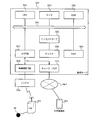
- FIG. 5 is a block diagram illustrating a hardware configuration example of the monitoring server 100. Unlike the sensor node 101, the monitoring server 100 operates based on an external power supply.
- the monitoring server 100 includes a CPU (Central Processing Unit) 501, a timer 502, a ROM 503, a RAM 504, a disk drive 505, a disk 506, and an I / O (Input / Output) circuit 507.
- the monitoring server 100 includes an internal bus 511 that connects the CPU 501, timer 502, ROM 503, RAM 504, disk drive 505, and I / O circuit 507.
- the CPU 501 is a control unit that controls the entire monitoring server 100.
- the ROM 503 is a storage unit that stores programs such as a boot program.
- the RAM 504 is a storage unit used as a work area for the CPU 501.
- the disk drive 505 controls reading / writing of data with respect to the disk 506 according to the control of the CPU 501.
- the disk 506 is a storage unit that stores data written under the control of the disk drive 505. Examples of the disk 506 include a magnetic disk and an optical disk.
- a wireless communication circuit 508 and an antenna 509 are connected to the I / O circuit 507. Accordingly, the monitoring server 100 can wirelessly communicate with the sensor node 101 by wirelessly communicating with the gateway 301 via the wireless communication circuit 508 and the antenna 509.
- a network I / F 510 is connected to the I / O circuit 507.
- the monitoring server 100 allows the external device such as the user terminal 302 via the network NET such as the Internet by the protocol processing of TCP (Transmission Control Protocol) / IP (Internet Protocol) via the network I / F 510. Can communicate with.
- wired communication or wireless communication can be applied to communication via the network I / F 510.
- the monitoring server 100 may be provided with input devices such as a keyboard, a mouse, and a touch panel. As a result, the developer can directly operate the monitoring server 100 via the input device. For example, an output device such as a display, a printer, or a buzzer may be provided in the monitoring server 100.
- the gateway 301 may have the same configuration.
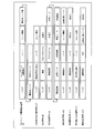
- FIG. 6 is an explanatory diagram showing an example of the basic data structure of a signal.
- the basic configuration of the signal includes a header, a command, a relay direction, additional information, and data.
- the header is given based on the communication protocol.
- the communication protocol differs between the communication between the sensor nodes 101, which is short-range wireless communication, and the communication between the monitoring server 100 and the aggregator ag, which is long-range wireless or wired. Therefore, in this embodiment, each signal header is replaced by an aggregate that relays between the plurality of sensor nodes 101 and the monitoring server 100.
- the command is information indicating the type of each signal.
- the relay direction is information indicating what kind of transmission destination it is. There are four types of relay directions: P2P, node, aggregator ag, and broadcast. The additional information differs depending on the type of relay direction.
- the relay direction When the relay direction is a node, it indicates that the signal is transmitted from the aggregator ag to the designated sensor node 101 by relay transfer, and the additional information includes relay information.
- the relay direction When the relay direction is the aggregator ag, it indicates that a signal is transmitted from the sensor node 101 to the aggregator ag. In this case, since each sensor node 101 transfers a signal with the parent node as a transmission destination at the time of relay transfer, the signal can reach the aggregator ag. Therefore, the additional information has only identification information indicating the transmission source.
- the relay direction is broadcast, the signal is transmitted to the entire surrounding sensor node 101, and therefore the additional information has only identification information indicating the transmission source.
- the search instruction signal s1 is a signal for instructing the sensor node 101 to search for the sensor node 101 that can respond to the signal transmitted from the own sensor node 101 to the sensor node 101 at a predetermined intensity.
- the search instruction signal s1 includes a header, information indicating a search instruction as a command, information indicating a node as a relay direction, and relay information as additional information.
- the search response signal s3 is a signal indicating a response to the search signal s2.
- the search response signal s3 includes a header, information indicating a search response as a command, information indicating P2P as a relay direction, identification information indicating a transmission destination and identification information indicating a transmission source as additional information, position information as data Have.
- the transmission destination here is the transmission source of the search signal s2.
- the sensor node 101 that can measure the position by its own sensor, such as GPS includes position information indicating the position in the search response signal s3 in the search response signal s3.
- the sensor node 101 whose position can be measured by the own sensor is also referred to as a reference point node.
- the connection instruction signal s10 is a signal instructing to connect the target sensor node 101 as a child node.
- the connection instruction signal s10 includes a header, information indicating a connection instruction as a command, information indicating a node as a relay direction, relay information of the sensor node 101 to be connected as additional information, identification information indicating a connection target node, Have
- the disconnection instruction signal s12 is a signal for the monitoring server 100 to instruct the sensor node 101 to disconnect from the network SNET.
- the disconnection instruction signal s12 includes a header, information indicating a disconnection instruction as a command, information indicating a node as a relay direction, and relay information as additional information.
- the node management information 1001 is information indicating a parent node, a child node, and a peripheral node for each sensor node 101.
- the node management information 1001 includes fields for a node ID, a node type, position information, a parent node ID, a child node number, a child node ID, a peripheral node number, and a peripheral node ID.
- a record (1001-i) By setting information in each field, it is stored as a record (1001-i).
- identification information that can uniquely identify the sensor node 101 is set.
- the node type field the type of sensor node 101 is set.
- the node types include an aggregator ag, a reference point node, a normal node, and a redundant node rnd.
- a normal node is a node whose position is unknown in advance and whose position has not been measured or whose position has not been determined by position measurement.
- the redundant node rnd is a node that has been disconnected by the disconnection instruction.
- the monitoring server 100 cannot determine the identification information indicating the sensor node 101 and the like, and thus cannot be set in the node management information 1001. Therefore, the sensor node 101 in which the redundant node rnd is set as the node type is a node disconnected from the network SNET by a disconnection instruction after joining the network SNET.
- FIG. 11 is a block diagram illustrating a functional configuration example of the sensor node 101.
- the sensor node 101 includes a control unit 1101, a reception unit 1102, a transmission unit 1103, and a storage unit 1104.
- the receiving unit 1102 is realized by the receiving circuit 422.
- the transmission unit 1103 is realized by the transmission circuit 421.
- the storage unit 1104 is realized by a storage device such as the RAM 405 and the nonvolatile memory 406, for example.
- the control unit 1101 is realized, for example, when the MCU 402 reads out a program stored in the storage unit 1104 and executes processing coded in the program. Various processing results by the control unit 1101 are stored in the storage unit 1104.
- FIG. 12 is an explanatory diagram showing an example of the contents stored in the storage unit of the sensor node 101.
- the storage unit 1104 has, for example, its own sensor node ID, connection information 1200, and position measurement information 1201.
- the position measurement information 1201 has fields of a transmission source ID and a reception intensity. Identification information that can uniquely identify the transmission source of the measurement signal s8 described later is set in the transmission source ID field. In the reception strength field, the reception strength of the measurement signal s8 described later is set. Here, the reception intensity indicates the intensity of the received signal.
- the reception strength is, for example, RSSI (Received Signal Strength Indicator) and is reception power [dBm].
- RSSI Receiveived Signal Strength Indicator
- the monitoring server 100 determines the position of each sensor node 101 using three-point surveying, and three pairs of the transmission source ID and the reception intensity are the position measurement information 1201. Should be set.
- the receiving unit 1102 has a function of receiving a signal from another sensor node 101 or the monitoring server 100.
- the reception unit 1102 can measure the reception intensity of the received signal.
- the transmission unit 1103 has a function of transmitting a signal to another sensor node 101 or the monitoring server 100.
- the transmission unit 1103 transmits a signal with a predetermined strength.
- the intensity for transmitting the measurement signal s8 and the search signal s2 described above is the same in all the sensor nodes 101, so that the monitoring server 100 can easily identify and search the position of each sensor node 101.
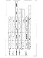
- FIG. 13 is an explanatory diagram showing an example of an operation sequence for provisional network SNET construction.
- the gateway 301 is omitted.
- the monitoring server 100 transmits a search instruction signal s1 to the sensor node 101-1 that is the aggregator ag (step S1301).
- the sensor node 101-1 transmits the search signal s2 by broadcasting (step S1302).
- sensor node 101-2 receives search signal s2 from sensor node 101-1, it transmits search response signal s3 to sensor node 101-1 (step S1303).
- the sensor node 101-1 monitors the search result signal s4 created by the search response signal s3 unless it is a child node of the other sensor node 101. It transmits to the server 100 (step S1304).
- the sensor node 101 that has received the search signal s2 transmitted from the sensor node 101-1 is only one of the sensor nodes 101-2. You may receive from the node 101.
- the sensor node 101-1 may create the search result signal s4 based on the search response signal s3 received within a predetermined time after transmitting the search signal s2.
- the predetermined time is, for example, a value determined by the developer of the system 300.
- the sensor node 101-1 transmits a connection instruction signal s10 to all the selected reference point nodes.
- the sensor node 101-1 randomly selects the maximum child node number mn from the selected reference point node, and the selected maximum child node number mn
- a connection instruction signal s10 is transmitted to the point node.
- the sensor node 101-1 transmits a connection instruction signal s10 to the sensor node 101-2 (step S1306).
- the monitoring server 100 When the monitoring server 100 receives the aggregated search result signal s5, the monitoring server 100 updates the total number of nodes based on the aggregated search result signal s5. Then, the monitoring server 100 ends the provisional network SNET construction when the total number of nodes reaches the prescribed number, and records the search result and selects the parent node candidate when the total number of nodes is less than the prescribed number. .
- the sensor node 101 with less overlap is selected as a parent node candidate.
- the monitoring server 100 repeats the processes such as the above-described steps S1306 to S1314.
- the monitoring server 100 ends the provisional network SNET construction.
- the position measurement process will be described with reference to FIG.
- FIG. 15 is an explanatory diagram showing an example of an operation sequence for position measurement.
- a description will be given assuming that there is a sensor node 101-N as the reference point node and the sensor node 101-M is around the sensor node 101-N.
- the gateway 301 is omitted.
- the transmission intensity of the measurement signal s8 transmitted by the sensor node 101 is constant, the sensor node 101 having a larger reception intensity loss is farther from the transmission source of the measurement signal s8 and has a smaller reception intensity loss. The closer the measurement signal s8 is to the transmission source.
- the transmission intensity of the measurement signal s8 is a predetermined intensity.
- the predetermined intensity is an intensity that can be set by the transmission circuit 421, and is a transmission intensity that is common to the sensor nodes 101.
- a function that can calculate the distance between the sensor nodes 101 based on the received intensity is stored in a storage device such as the disk 506.
- the position measurement signal s8 is transmitted by using the sensor node 101 newly determined as described above as a reference point node, so that the region range where the position can be measured is obtained. spread. If the positions of all the sensor nodes 101 are finally determined, the position measurement ends. In addition, when the monitoring server 100 cannot receive the measurement result signal s9 even after a predetermined time has elapsed since the last transmission of the measurement signal output instruction signal s7, the position measurement ends. For example, even if the measurement result signal s9 cannot be received even after a certain period of time has elapsed, it is only necessary that the density of the sensor nodes 101 to be finally operated is equalized. There may be.
- the monitoring server 100 performs a distribution density analysis process after the position measurement process is completed.
- the monitoring server 100 generates area information indicating a divided area a obtained by dividing an area simulating the arrangement area area into squares of a predetermined size.
- the predetermined size may be set by the developer of the system 300 and is determined based on the reachable distance according to the transmission intensity of the signal transmitted from the sensor node 101.
- FIG. 16 is an explanatory diagram showing an example of distribution density analysis.
- FIG. 16 shows a divided area a obtained by dividing the arrangement area area into a mesh.
- the communicable area ca and the divided area a illustrated in FIG. 16 are areas on the simulation space of the monitoring server 100.
- the monitoring server 100 determines whether or not the measurement area sa of the sensor node 101 includes at least a part of the divided area a for each of the plurality of sensor nodes 101.
- the measurement area sa is an area that can be measured by the sensor 401.
- the measurement area sa is determined by the position of the sensor node 101 and the predetermined distance d1.
- the measurable area of the sensor 401 included in each sensor node 101 is determined in advance.
- the predetermined distance d1 is a value determined in advance according to the type and performance of the sensor 401. For example, when it is determined that at least a part of the measurement area sa of the sensor node 101 is included in each of the divided areas a, the monitoring server 100 increases the density of the divided area a. Further, the increasing amount may be constant in the measurement area sa, or the increasing amount may be increased as the distance from the sensor node 101 is closer to the sensor node 101, for example. This may be changed according to the characteristics of the sensor 401 to be mounted. In this way, the distribution density in the arrangement area area is specified. As shown in FIG.
- the measurement area sa and the communicable area ca are different.
- the communicable area ca is determined by the position of the sensor node 101 and the predetermined distance d2.
- the predetermined distance d2 is determined by the signal transmission intensity by the transmission circuit 421, the performance of the reception circuit 422, and the like.
- the monitoring server 100 separates the sensor node 101 that includes the divided area a having the highest density among the divided areas a in the measurement area sa. First, the monitoring server 100 selects the divided area a having the highest density as the target divided area a. Next, the monitoring server 100 excludes the sensor node 101 from the network SNET for each of the plurality of divided areas a corresponding to each of the sensor nodes 101 including at least a part of the selected divided area a in the measurement area sa. The density in this case is derived.
- the monitoring server 100 calculates a standardized effect value for each of the sensor nodes 101 including the target divided area a in the measurement area sa.
- the standardization effect value is a value indicating how close the density of the target divided region a approaches the average density by separating the sensor node 101.
- the monitoring server 100 determines the sensor node 101 having the largest calculated standardization effect value as a candidate for separation.
- the average density is a value obtained by dividing “the area of the measurement region sa measurable by the sensor 401 ⁇ the defined number nn” by the area of the arrangement region area.
- the specified number nn is the number of sensor nodes 101 that can be included in the provisional network SNET described above.
- ⁇ 1i is the density before separation of the i-th divided region a
- ⁇ 2i is the density after separation of the i-th divided region a
- ⁇ a is the above-mentioned average density.
- the standardization effect value represents how close to the average density is due to the separation, so the difference between the density before separation and the average density is calculated from the absolute value of the difference between the density before separation and the average density. This is the sum of the values obtained by subtracting the absolute value of the difference.
- the monitoring server 100 sets the target candidate sensor node 101 to a sensor node 101 that cannot be disconnected. .
- the monitoring server 100 selects a divided area a other than the selected divided area a from the plurality of divided areas a. A new divisional area a is selected. Further, the monitoring server 100 notifies the developer that the arrangement area area cannot be leveled if there is no sensor node 101 that can be separated in the divided area a having a density higher than the average density.
- the notification method may be output to the user terminal 302 via the network SNET, for example, and is not particularly limited.
- the monitoring server 100 separates and selects the target candidate sensor node 101 having the highest standardization effect value as the target sensor node 101 among the target candidate sensor nodes 101 that do not have the divided region a in which the density is smaller than the threshold th. Then, the monitoring server 100 transmits a separation instruction signal s12 with the selected separation target as a transmission destination.
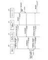
- FIG. 17 is an explanatory diagram showing an example of an operation sequence for connection / disconnection. A detailed example of the disconnection instruction is shown in steps S1711 to S1716.
- FIG. 17 shows an example in which the sensor node 101-Y that is a child node of the sensor node 101-X is disconnected from the network SNET.
- the gateway 301 is omitted.
- the monitoring server 100 transmits the disconnection instruction signal s12 with the sensor node 101-Y as a target to be disconnected and the sensor node 101-Y as a transmission destination to the sensor node 101-1 that is the aggregator ag (step S1711).
- the sensor node 101-1 transfers the disconnection instruction signal s12 (step S1712).
- the disconnection instruction signal s12 arrives from the sensor node 101-1 to the sensor node 101-X by relay transfer.
- the sensor node 101-X transfers the disconnection instruction signal s12 (step S1713).
- the sensor node 101-Y transmits a leave request signal s13 to the sensor node 101-X that is the parent node (step S1714).
- the sensor node 101-Y deletes the sensor node 101-X from the parent node and transitions to the redundant operation mode (step S1715). When transitioning to the redundant operation mode, measurement operation and transfer operation are not performed. When the sensor node 101-X receives the leave request signal s13, the sensor node 101-X deletes the sensor node 101-Y from the child node (step S1716). As a result, the sensor node 101-Y can be disconnected from the provisional network SNET.
- the monitoring server 100 performs a node addition process for adding the sensor node 101 to the network SNET in the low-density divided area a. Since it is unknown whether there is a sensor node 101 to be added, the monitoring server 100 cannot use the leveling effect value. Therefore, the monitoring server 100 selects the divided area a having the lowest density from among the divided areas a as the additional target candidate divided area a. Then, the monitoring server 100 transmits a search instruction signal s1 with the sensor node 101 including at least a part of the target candidate division area a in the measurement area sa as a transmission destination. Alternatively, the monitoring server 100 transmits a search instruction signal s1 with the sensor node 101 including at least a part of the target candidate division area a in the communicable area ca as a transmission destination.
- the sensor node 101 When the sensor node 101 receives the search instruction signal s1 to which the sensor node 101 is a transmission destination, the sensor node 101 performs a search process. Since the search process is the same as the sequence shown in FIG. 13, detailed description thereof is omitted.
- the monitoring server 100 receives the aggregated search result signal s5, the monitoring server 100 determines whether there is a redundant node rnd with no connection history around the transmission destination of the search instruction signal s1. When it is determined that there is a redundant node rnd with no connection record, the monitoring server 100 determines whether or not a child node connection is possible. The monitoring server 100 determines that the child node connection is not possible when the transmission destination of the search instruction signal s1 has the maximum number of child nodes mn.
- the monitoring server 100 determines that child node connection is possible when the number of child nodes that the transmission destination of the search instruction signal s1 has is less than the maximum child node number mn.
- the monitoring server 100 transmits the connection instruction signal s10 to one of the redundant nodes rnd having no connection record with the selected connection node cnd as the transmission destination.
- FIG. 17 shows an example in which the sensor node 101-Y is connected as a child node of the sensor node 101-X.
- the monitoring server 100 transmits the connection instruction signal s10 instructing to connect the sensor node 101-Y with the sensor node 101-X as a transmission destination (step S1701).
- the sensor node 101-1 that is an aggregator ag transfers the connection instruction signal s10 (step S1702).
- the connection instruction signal s10 arrives from the sensor node 101-1 to the sensor node 101-X by relay transfer.
- the sensor node 101-X transmits a connection request signal s11 with the sensor node 101-Y as a transmission destination (step S1703).
- the sensor node 101-X records the sensor node 101-Y as a child node (step S1704).
- the sensor node 101-Y receives the connection request signal s11
- the sensor node 101-Y records the sensor node 101-X as a parent node (step S1705). Thereby, the sensor node 101 can be added to the network SNET.
- the monitoring server 100 determines that child node connection is not possible. When it is determined in this way, the monitoring server 100 may disconnect the child node that has already been connected to the transmission destination of the search instruction signal s1, and connect one of the redundant nodes rnd with no connection record. However, when the already connected child node is disconnected and there is a divided region a whose density is equal to or less than the threshold th, the monitoring server 100 does not perform the disconnection. In addition, since the sensor node 101 cannot be newly added to the network SNET because it cannot be disconnected, the monitoring server 100 may notify the developer of information indicating that it cannot be made uniform.
- the monitoring server 100 transmits information indicating that uniformization cannot be performed to the user terminal 302.
- the information indicating that it cannot be made uniform may include information indicating which divided region a has a density equal to or lower than the threshold th.
- the information indicating that it cannot be made uniform may include densities corresponding to all the divided areas a.
- FIG. 18 is a flowchart illustrating an example of a communication network control processing procedure by the monitoring server 100.
- the monitoring server 100 performs provisional network construction processing (step S1801).
- the monitoring server 100 performs a position measurement process (step S1802).
- the monitoring server 100 performs distribution density analysis processing (step S1803).
- the monitoring server 100 determines whether there is a divided area a having a density equal to or less than the threshold th (step S1804).
- step S1804 If there is a divided area a whose density is equal to or less than the threshold th (step S1804: Yes), the monitoring server 100 performs density difference elimination processing (step S1805), and returns to step S1802.
- step S1804: No the monitoring server 100 ends a series of processes. As a result, the operation of the constructed network SNET can be started.
- FIG. 19 and 20 are flowcharts showing an example of a provisional network construction processing procedure by the monitoring server 100.
- the monitoring server 100 transmits a search instruction signal s1 to the aggregator ag (step S1901).
- the monitoring server 100 enters a reception waiting state (step S1902).
- the monitoring server 100 determines whether or not the search result signal s4 has been received (step S1903). If it is determined that it has not been received yet (step S1903: No), the monitoring server 100 returns to step S1903. If it is determined that it has been received (step S1903: YES), the monitoring server 100 stores the search result (step S1904).
- the monitoring server 100 sets a record for the aggregator ag in the node management information 1001 based on the received search result.
- the monitoring server 100 transmits a network construction instruction signal s6 to the aggregator ag (step S1905). Then, the monitoring server 100 enters a reception waiting state (step S1906).
- the monitoring server 100 determines whether or not an aggregate search result signal s5 for the network SNET construction instruction has been received (step S2001). When it is determined that the aggregated search result signal s5 has not been received (step S2001: No), the monitoring server 100 returns to step S2001. When it is determined that the aggregated search result signal s5 has been received (step S2001: Yes), the monitoring server 100 updates the total number of nodes (step S2002).
- the monitoring server 100 determines whether or not the specified number nn has been exceeded (step S2003). When it is determined that the specified number nn has been exceeded (step S2003: Yes), the monitoring server 100 ends a series of processes for the provisional network construction process. When it is determined that the specified number nn is not exceeded (step S2003: No), the monitoring server 100 stores the search result (step S2004).
- the monitoring server 100 selects a parent node candidate (step S2005).
- the monitoring server 100 determines whether there is a parent node candidate (step S2006). When it is determined that there is no parent node candidate (step S2006: No), the monitoring server 100 ends a series of processes for the provisional network construction process.
- step S2006 when it is determined that there is a parent node candidate (step S2006: Yes), the monitoring server 100 transmits a network construction instruction signal s6 with the parent node candidate as a transmission destination (step S2007). Then, the monitoring server 100 enters a reception waiting state (step S2008), and returns to step S2001. In this way, by repeating the processing from step S2001 to step S2007, a provisional network SNET including the prescribed number nn of sensor nodes 101 is constructed.
- FIG. 21 is a flowchart showing an example of a position measurement processing procedure by the monitoring server 100.
- the monitoring server 100 identifies the reference point node connected to the temporary network SNET from the search result (step S2101).
- the monitoring server 100 transmits a measurement signal output instruction signal s7 with all reference point nodes as transmission destinations (step S2102).
- the monitoring server 100 sets a timeout time in the timer 502 and enters a reception waiting state (step S2103).
- the monitoring server 100 determines whether a signal is received (step S2104).
- step S2104 determines whether or not a timeout has occurred (step S2105). When it is determined that a time-out has occurred (step S2105: Yes), the monitoring server 100 ends a series of processes related to the position measurement process. If it is determined that the timeout has not occurred (step S2105: NO), the monitoring server 100 returns to step S2104.
- the monitoring server 100 estimates and records the position of the transmission source from the received measurement information signal (step S2106).
- the monitoring server 100 estimates the position of the transmission source of the measurement information signal based on the three combinations of the transmission source and the reception intensity of the measurement signal s8 included in the measurement information signal using three-point surveying. To do.
- the monitoring server 100 determines whether there is a sensor node 101 whose position is unknown (step S2107).
- the monitoring server 100 determines whether or not the position of the sensor node 101 whose record is set in the node management information 1001 is unknown.
- the monitoring server 100 ends a series of processes related to the position measurement process.
- step S2107 If it is determined that there is a sensor node 101 whose position is unknown (step S2107: Yes), the monitoring server 100 transmits a measurement signal output instruction signal s7 with the transmission source of the measurement information signal as the transmission destination (step S2108). Return to step S2103.
- FIG. 22 is a flowchart illustrating an example of a distribution density analysis processing procedure by the monitoring server 100.
- the monitoring server 100 generates divided area information 102 obtained by dividing the arrangement area area into a plurality of divided areas a (step S2201).
- the monitoring server 100 acquires location information indicating the location of the connection node cnd included in the temporary network SNET (step S2202).
- the monitoring server 100 determines whether or not there is an unselected connection node cnd among the connection nodes cnd whose positions have been determined (step S2203). When it is determined that there is no unselected connection node cnd (step S2203: No), the monitoring server 100 ends the series of processes. When it is determined that there is an unselected connection node cnd (step S2203: Yes), the monitoring server 100 selects one connection node cnd from the unselected connection nodes cnd (step S2204). The monitoring server 100 identifies the measurement area sa of the sensor included in the selected connection node cnd based on the position of the selected connection node cnd and the predetermined distance (step S2205). Here, the monitoring server 100 stores the measurement area information 103 indicating the specified measurement area sa in the storage unit 904.
- the monitoring server 100 identifies the divided area a included in the measurement area sa at least a part of the plurality of divided areas a (step S2206). Then, the monitoring server 100 increases the density corresponding to the identified divided area a based on the identified divided area a and the selected connection node cnd (step S2207), and returns to step S2203.
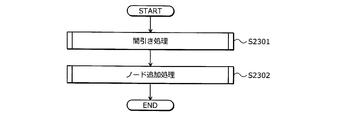
- FIG. 23 is a flowchart illustrating an example of a density difference elimination processing procedure by the monitoring server 100.
- the monitoring server 100 performs a thinning process (step S2301).
- the monitoring server 100 performs node addition processing (step S2302), and ends a series of processing relating to density difference elimination processing.
- the monitoring server 100 can prevent the number of sensor nodes 101 connected to the provisional network SNET from changing by adding the connection node cnd after thinning out.
- FIG. 24 is a flowchart illustrating an example of a thinning process procedure by the monitoring server 100.
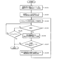
- the monitoring server 100 selects the divided area a having the highest density among the unselected divided areas a (step S2401).
- the monitoring server 100 determines whether there is a selectable divided area a (step S2402).
- the monitoring server 100 calculates a standardized effect value for a connection node cnd that includes at least a part of the selected divided area a in the measurement area sa. (Step S2403).
- the monitoring server 100 determines whether there is a connection node cnd that can be disconnected (step S2404).
- step S2404 When it is determined that there is no connection node cnd that can be disconnected (step S2404: No), the monitoring server 100 returns to step S2402. If it is determined that there is a connection node cnd that can be disconnected (step S2404: Yes), the monitoring server 100 transmits a disconnection instruction signal s12 with the connection node cnd having the maximum standardized effect value as the transmission destination (step S2405). Then, a series of processes relating to the thinning process is completed. If it is determined that there is no selectable divided area a (step S2402: No), the monitoring server 100 notifies that the area cannot be uniformed (step S2406), and all the processes are terminated because an error has occurred.
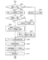
- FIG. 25 is a flowchart illustrating an example of a node addition processing procedure by the monitoring server 100.
- the monitoring server 100 selects the divided area a having the lowest density among the unselected divided areas a (step S2501).
- the monitoring server 100 identifies and selects a connection node cnd that includes at least a part of the selected divided area a in the communicable area ca (step S2502).
- the monitoring server 100 determines whether there is a selectable connection node cnd (step S2503). When it is determined that there is a selectable connection node cnd (step S2503: Yes), the monitoring server 100 transmits a search instruction signal s1 with the selected connection node cnd as a transmission destination (step S2504).
- the monitoring server 100 determines whether there is a redundant node rnd with no connection record in the vicinity (step S2505). When it is determined that there is no redundant node rnd with no connection record in the vicinity (step S2505: No), the monitoring server 100 returns to step S2503. On the other hand, if it is determined that there is a redundant node rnd with no connection record in the vicinity (step S2505: Yes), the monitoring server 100 determines whether or not a child node connection is possible (step S2506). When it is determined that the child node connection is possible (step S2506: Yes), the monitoring server 100 transmits a connection instruction signal to one of the redundant nodes rnd having no connection record with the selected connection node cnd as the transmission destination. s10 is transmitted (step S2507), and a series of processing relating to the node addition processing ends. When it is determined that the child node connection is not possible (step S2506: No), the monitoring server 100 returns to step S2503.
- the monitoring server 100 determines whether a redundant node rnd with no connection record has been found (step S2508). Information regarding whether or not there is a connection record may be stored in the storage unit 904. When the monitoring server 100 sets the sensor node 101 as any child node and then disconnects it from the network SNET, the monitoring server 100 associates the identification information indicating the sensor node 101 with information indicating that the sensor node 101 has been set as a child node, Stored in 904.
- step S2508 If it is determined that a redundant node rnd with no connection record has been found (step S2508: Yes), the monitoring server 100 separates each child node of the connection node cnd that has found a redundant node rnd with no connection record. In step S2509, the standardization effect value is calculated. Next, the monitoring server 100 determines whether or not there is a connection node cnd that can be disconnected (step S2510). Here, the monitoring server 100 determines the separation target from the separation target candidates that do not have the divided region a in which the density is equal to or lower than the threshold th when it is assumed that the separation target is separated. For this reason, when there is no separation target that does not include the divided region a whose density is equal to or less than the threshold th, it is determined that there is no connection node cnd that can be separated.
- step S2510: Yes When it is determined that there is a connection node cnd that can be disconnected (step S2510: Yes), the monitoring server 100 transmits a disconnection instruction signal s12 with the connection node cnd having the maximum standardized effect value as the transmission destination (step S2511). The process proceeds to step S2507.
- step S2508: No When it is determined that a redundant node rnd with no connection record has not been found (step S2508: No), the monitoring server 100 notifies the developer that it cannot be made uniform (step S2512), and ends a series of processing as an error. To do. Examples of the notification method include transmitting information indicating that the user terminal 302 cannot be uniformized. If it is determined that there is no connection node cnd that can be disconnected (step S2510: NO), the monitoring server 100 proceeds to step S2512.
- FIG. 26 to FIG. 29 are flowcharts showing an example of processing procedures performed by the sensor node 101.
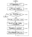
- the sensor node 101 When the sensor node 101 is activated (step S2601), the sensor node 101 enters a signal reception waiting state (step S2602). Next, the sensor node 101 determines whether or not a signal has been received (step S2603). If it is determined that the information has not been received (step S2603: NO), the sensor node 101 returns to step S2603.
- step S2603 when it is determined in step S2603 that the search instruction signal s1 has been received (step S2603: search instruction), the sensor node 101 searches for a neighboring node (step S2604).
- the sensor node 101 transmits a search result signal s4 with the parent node or gateway 301 as a transmission destination (step S2605), and returns to step S2602.
- the only sensor node 101 that can set the gateway 301 as a transmission destination is the aggregator ag.
- step S2603 when it is determined in step S2603 that the aggregate search result signal s5 has been received (step S2603: aggregate search result), the sensor node 101 transmits the received aggregate search result to the gateway 301 (step S2701). Then, the sensor node 101 enters an instruction reception waiting state (step S2702) and returns to step S2603.
- step S2603 when it is determined in step S2603 that the measurement signal output instruction signal s7 has been received (step S2603: measurement signal output instruction), the sensor node 101 transmits the measurement signal s8 (step S2711). Then, the sensor node 101 enters an instruction reception waiting state (step S2712), and the process returns to step S2603.
- step S2721 the sensor node 101 determines whether measurement information has been transmitted (step S2721). If the position measurement has already been completed, it is determined that the measurement information has been transmitted.
- step S2721: YES When it is determined that the measurement information has been transmitted (step S2721: YES), the sensor node 101 proceeds to step S2725.
- the sensor node 101 records the transmission source ID and the reception intensity (step S2722). Then, the sensor node 101 determines whether or not a predetermined number of measurement signals s8 that are different transmission sources have been received (step S2723).
- the predetermined number is, for example, a predetermined value. As described above, if the arrangement area area is a plane, the predetermined number may be three.
- step S2723: NO If it is determined that the predetermined number has not been received (step S2723: NO), the sensor node 101 proceeds to step S2725. When it is determined that the predetermined number has been received (step S2723: Yes), the sensor node 101 transmits a measurement information signal including the recorded measurement information to the aggregator ag (step S2724). Next, the sensor node 101 enters an instruction reception waiting state (step S2725) and returns to step S2603.
- step S2801 determines whether or not the number of peripheral nodes> the maximum number of child nodes mn. If it is determined that the number of peripheral nodes> the maximum number of child nodes mn (step S2801: YES), the sensor node 101 selects a reference point node from the peripheral nodes (step S2802).
- the sensor node 101 determines whether or not the number of reference point nodes> the maximum number of child nodes mn (step S2803). When it is determined that the number of reference point nodes> the maximum number of child nodes mn (step S2803: Yes), the sensor node 101 randomly selects the sensor node 101 from the reference point nodes within the maximum number of child nodes mn. Are connected (step S2804). Next, the sensor node 101 transmits a search instruction signal s1 to all child nodes (step S2808). Then, the sensor node 101 enters a search result reception waiting state for the transmitted search instruction signal s1 (step S2809).
- the sensor node 101 When the sensor node 101 receives the search result signal s4, the sensor node 101 transmits the aggregate search result and child node information to the aggregator ag or the gateway 301 (step S2810). The sensor node 101 enters an instruction reception waiting state (step S2811) and returns to step S2603.
- step S2803 when it is determined that the number of reference point nodes> the maximum number of child nodes mn is not satisfied (step S2803: No), the sensor node 101 connects all reference point nodes (step S2805). The sensor node 101 selects and connects the sensor node 101 at random within the maximum number of child nodes mn (step S2806), and proceeds to step S2808.
- step S2801 If it is determined in step S2801 that the number of peripheral nodes> the maximum number of child nodes mn is not satisfied (step S2801: NO), the sensor node 101 connects all the peripheral sensor nodes 101 (step S2807), and proceeds to step S2808. .
- step S2603 connection instruction
- the sensor node 101 outputs the sensor node 101 instructed by the connection instruction signal s10 as a child node ( Step S2901). Then, the sensor node 101 enters a reception waiting state (step S2902) and returns to step S2603.
- step S2603 when it is determined in step S2603 that the disconnection instruction signal s12 has been received (step S2603: disconnection instruction), the sensor node 101 transmits a leave request signal s13 to the parent node (step S2911). The sensor node 101 makes a transition to the redundant operation mode (step S2912). Then, the sensor node 101 enters a reception waiting state (step S2913) and returns to step S2603.
- the monitoring server 100 analyzes, for each divided area of the arrangement area, the number of connection nodes of the network SNET that includes at least a part of the divided area in the measurement area, and determines the network connection node according to the analysis result. To change. Thereby, the distribution of redundant nodes can be made uniform, and the reliability can be improved.
- the monitoring server 100 performs control to add a redundant node including at least a part of the divided area selected based on the density according to the number of connection nodes in the sensor measurement area to the network. Specifically, the monitoring server 100 transmits a signal instructing to join the network to a communication node that includes at least a part of the selected divided area in the sensor measurement area of the sensor node. Thereby, the distribution of connection nodes can be made uniform, and the arrangement area can be measured uniformly.
- the selected divided area is the divided area having the smallest value according to the number of connection nodes. Thereby, it is possible to measure a region that is unlikely to be measured by the sensor node.
- the monitoring server 100 controls a configuration node that identifies a configuration node that includes at least a part of the selected divided region in the communicable region from among a plurality of configuration nodes, and adds nodes around the identified configuration node to the network To do.
- the monitoring server 100 excludes, from the network, a construction node selected from a construction node that includes at least a part of the selected divided area in the measurement area among the plurality of construction nodes.
- the divided area selected here is the divided area having the largest derived value among the plurality of divided areas.
- the monitoring server 100 transmits a signal instructing to be excluded from the network to the selected construction node. Thereby, redundant nodes can be provided evenly in the arrangement area.
- the monitoring server 100 determines the separation target from the construction node that includes at least a part of the selected divided region in the measurement region, the density for each of the divided regions when it is assumed that each of the construction nodes is separated. Is derived. Then, the monitoring server 100 determines a separation target based on the derived density.
- the monitoring server 100 performs control to add a redundant node to the network after removing the construction node from the network.
- the number excluded and the number added are equal, the number of construction nodes in the network can be made constant. Therefore, it is possible to prevent the number of redundant nodes from being too small or too large, and it is possible to improve long-term reliability.
- the monitoring server 100 does not execute a process for performing control to change when there is no divided area in which the derived density does not satisfy the predetermined condition among the plurality of divided areas.
- the monitoring server 100 executes processing for performing control to change.
- the network can be changed only when redundant nodes are not provided evenly in the arrangement area.
- the monitoring server 100 transmits a signal instructing the output of the measurement signal to the periphery to the construction node whose position is already known among the construction nodes. Then, the monitoring server 100 receives a predetermined number of combinations of the reception intensity of the measurement signal and the identification information indicating the transmission source of the measurement signal from the construction node that has received the predetermined number of measurement signals from the known construction node. The monitoring server 100 identifies the location of the received construction node based on the predetermined number of combinations and the location of the construction node that has been determined. Thereby, even if the positions of all the sensor nodes are not known in advance, the positions of the sensor nodes included in the network can be specified, and the measurement area of the sensor nodes can be specified. Therefore, since it is not necessary to mount a GPS unit on all sensor nodes, the cost can be reduced.
- the amount of information related to sensor nodes included in the network for management by the monitoring server 100 can be reduced.
- the communication network control method described in this embodiment can be realized by executing a communication network control program prepared in advance on a computer such as a personal computer or a workstation.
- the communication network control program is recorded on a computer-readable recording medium such as a magnetic disk, an optical disk, or a USB (Universal Serial Bus) flash memory, and is executed by being read from the recording medium by the computer.
- the communication network control program may be distributed via a network NET such as the Internet.
Landscapes
- Engineering & Computer Science (AREA)
- Computer Networks & Wireless Communication (AREA)
- Signal Processing (AREA)
- Computer Security & Cryptography (AREA)
- Mobile Radio Communication Systems (AREA)
- Arrangements For Transmission Of Measured Signals (AREA)
Abstract
監視サーバ(100)は、ネットワーク(SNET)に含まれる接続ノード(cnd)の各々について、通信ノードが有するセンサの測定領域(sa)を示す測定領域情報(103)を取得する。監視サーバ(100)は、配置領域(area)を分割した複数の分割領域(a)を示す分割領域情報(102)を取得する。監視サーバ(100)は、取得した分割領域情報(102)が示す複数の分割領域(a)の各々について、接続ノード(cnd)のうち、取得した測定領域情報(103)が示す測定領域(sa)に分割領域(a)の少なくとも一部が含まれる接続ノード(cnd)の数に応じた値を導出する。監視サーバ(100)は、複数の分割領域(a)の各々について導出した密度に応じて、ネットワーク(SNET)に含まれる通信ノードを変更する制御を行う。
Description
本発明は、通信網制御方法、通信網制御プログラム、システム、および記録媒体に関する。
従来、無線により接続可能な複数の通信ノードによってネットワークを構築する技術が公知である。例えば、送信先ノードから送信元ノードへ所定の通信経路によってパケットを送るときに、所定の通信経路上にある中間ノードのうち、送信先ノードからのホップカウントが最小となるノードと最大になるノードとのそれぞれの通信経路を設定する技術が公知である(例えば、以下特許文献1参照。)。また、例えば、無線により接続可能な複数のノードがあって、近傍のノードを検出し、クラスターを形成し、近傍のクラスター同士を接続してネットワークを構築する技術が公知である(例えば、以下特許文献2参照。)。また、例えば、クラスターにグループ化された複数のノードと該複数のノードと接続する複数の無線リンクとを有し、送り元ノードから目標ノードまでのルートを決定する技術が公知である(例えば、以下特許文献3参照。)。
また、例えば、複数のセンサが無線通信によるネットワークにおいて、位置が予め判っている第1の基準センサと第2の基準センサの2個の基準センサを用い当該2個の基準センサとの距離情報に基づき、対象となる第3のセンサのセンサ位置を標定する技術が公知である(例えば、以下特許文献4参照。)。
しかしながら、配置した通信ノード群の一部をネットワークに含まれない冗長ノードとする場合に、冗長ノードの分布が均一でないと、ネットワークの信頼性を向上させることができないという問題点がある。
1つの側面では、ネットワークの信頼性の向上を図ることができる通信網制御方法、通信網制御プログラム、システム、および記録媒体を提供することを目的とする。
本発明の一側面によれば、本発明は、配置領域に設置される複数の通信ノードのうち、通信網に含まれる一部の通信ノードの各々について、前記通信ノードが有するセンサの測定領域を示す測定領域情報を取得し、前記配置領域を分割した複数の分割領域を示す分割領域情報を取得し、取得した前記分割領域情報が示す複数の分割領域の各々について、前記一部の通信ノードのうち、取得した前記測定領域情報が示す測定領域に前記分割領域の少なくとも一部が含まれる通信ノードの数に応じた値を導出し、前記複数の分割領域の各々について導出した前記値に応じて、前記通信網に含まれる通信ノードを変更する制御を行う通信網制御方法、通信網制御プログラム、システム、および記録媒体が提案される。
本発明の一態様によれば、信頼性の向上を図ることができる。
以下に添付図面を参照して、本発明にかかる通信網制御方法、通信網制御プログラム、システム、および記録媒体の実施の形態を詳細に説明する。
図1は、本発明にかかる監視サーバによる動作例を示す説明図である。監視サーバ100は、配置領域areaに配置される複数のセンサノード101のうち、ネットワークSNETの構築を制御するコンピュータであり、複数のセンサノード101と通信可能な通信装置である。センサノード101は、センサと小型の無線通信回路を有する通信ノードである。センサノード101が互いに通信を行うことにより通信網を形成する。通信網は、ネットワークSNETと称する。
配置領域areaに配置される複数のセンサノード101のうち、一部のセンサノード101は、ネットワークSNETに含まれるが、残余のセンサノード101は、ネットワークSNETに含まれない。ここで、ネットワークSNETに含まれるセンサノード101を接続ノードcndとも称する。また、複数のセンサノード101のうち、接続ノードcnd以外のセンサノード101は、冗長ノードrndとも称する。後述する詳細な実施例では、監視サーバ100によってネットワークSNETが構築されるが、ここではネットワークSNETは構築済みである。図1では、接続ノードcnd間は線によって接続されているが、上述したように実際には接続ノードcnd間は無線通信によって接続される。
システムの運用中に、接続ノードcndは、センサの測定動作、測定動作によって得られたデータの送信動作、他の接続ノードcndからのデータの転送動作などを行うが、冗長ノードrndは、測定動作、データの転送動作などを行わない。そのため、冗長ノードrndは、経年劣化の度合いが接続ノードcndと比較して低い。例えば長期間稼働して経年劣化などによって故障した接続ノードcndがあるときに、当該故障した接続ノードcndの周辺にある冗長ノードrndがあらたにネットワークSNETに追加されれば、長期的に配置領域area内の測定動作を行うことができる。そのため、システムの信頼性を向上させることができる。
しかしながら、故障した接続ノードcndの周辺に冗長ノードrndがない場合、配置領域areaのうち故障した接続ノードcndが配置された周辺の領域が測定されなくなる。そのため、一部のセンサノード101を冗長ノードrndとする場合、複数のセンサノード101が配置領域area内に均一に配置されてあっても、冗長ノードrndが均一に配置されていなければ、信頼性が低下することになる。
そこで、本実施の形態では、配置領域areaの分割領域aごとに、該分割領域aを測定領域saに少なくとも一部が含まれるネットワークSNETの接続ノードcndの数を解析し、解析結果によってネットワークSNETの接続ノードcndを変更する。これにより、冗長ノードrndの分布を均一化させることができ、信頼性の向上を図ることができる。
まず、監視サーバ100は、ネットワークSNETに含まれる接続ノードcndの各々について、前記通信ノードが有するセンサの測定領域saを示す測定領域情報103を取得する。例えば、センサノード101-1の測定領域saは、測定領域sa-1である。測定領域saについては、センサノード101の位置とセンサノード101が有するセンサの測定可能距離とによって表される。例えば、センサノード101の位置は、緯度や経度などであってもよいし、配置領域area内の相対的な位置であってもよい。配置領域area内の相対的な位置とは、例えば、配置領域areaを模擬するシミュレーション空間上に定義された軸に基づく座標である。より具体的には、図1に示すように配置領域areaが四角形であれば、左下角を原点とした場合の座標であってもよい。測定領域情報103の取得方法としては、例えば、監視サーバ100は、暫定ネットワークSNETを構築する際にセンサノード101へ位置の測定を指示する信号を送信することにより、当該信号に対する応答信号として各センサノード101の位置を取得する。ここで、ネットワークSNETでは、送信先と送信元との距離が信号を直接通信可能な距離以内でない場合、マルチホップ通信を利用したリレー転送によって信号を送信先から送信元まで到達させる。
つぎに、監視サーバ100は、配置領域areaを分割した複数の分割領域aを示す分割領域情報102を取得する。ここでは、監視サーバ100は、配置領域areaを物理的に分割するのではない。監視サーバ100は、配置領域areaを模擬するシミュレーション空間上において配置領域areaを複数の分割領域aに分割し、分割領域aを示す分割領域情報102を生成することにより、分割領域情報102を取得する。分割領域情報102は、センサノード101の位置と同様に緯度や経度などによって表されてもよいし、シミュレーション空間上に定義された軸に基づく座標であってもよい。具体的には、監視サーバ100は、所定サイズによって配置領域areaを分割する。所定サイズは、予め開発者によって定められる。所定サイズが小さいほど、後述する密度がより詳細に特定可能となる。ここでは、配置領域areaは、a1~a25までの25の分割領域aに分割される。図1では、a1~a25の符号の一部を省略して記載する。
つぎに、監視サーバ100は、分割領域情報102が示す複数の分割領域aの各々について、接続ノードcndのうち、取得した測定領域情報103が示す測定領域saに分割領域aの少なくとも一部が含まれる接続ノードcndの数に応じた値を導出する。ここで、導出される値を密度とも称する。これにより、配置領域areaの分布密度が特定可能となる。ここでは、例えば分割領域aに対応する密度が大きい値であるほど、密度が高いとし、分割領域aの少なくとも一部を測定領域saに含む接続ノードcndの数が多いとする。これに対して、例えば分割領域aに対応する密度が小さい値であるほど、密度が低いとし、分割領域aの少なくとも一部を測定領域saに含む接続ノードcndの数が少ないとする。図1の例では、分割領域a22の密度が最も低く、分割領域a19の密度が最も高い。図1の例では、測定領域saに分割領域aの少なくとも一部が含まれる接続ノードcndの数そのものを密度としているが、監視サーバ100は、測定領域saと分割領域aとの重複度合いに基づいて密度を増加させる増加量を変えてもよい。
つぎに、監視サーバ100は、複数の分割領域aの各々について導出した密度に応じて、ネットワークSNETに含まれる通信ノードを変更する制御を行う。例えば、密度が低い分割領域aについては、冗長ノードrndの数が多い可能性が高い。換言すると、密度が低い分割領域aについては、接続ノードcndの数が少ない可能性が高い。そのため、現状の分割領域aの測定が行われない可能性が高い。そこで、監視サーバ100は、複数の冗長ノードrndから、複数の分割領域aのうち導出した密度に基づき選択した分割領域aの少なくとも一部を冗長ノードrndが有するセンサの測定領域saに含む冗長ノードrndをネットワークSNETに追加する。例えば、選択された分割領域aは、最も密度が低い分割領域aであってもよい。または、例えば、監視サーバ100は、複数の分割領域aのうち導出した密度が所定条件を満たさない分割領域aを選択する。所定条件とは、密度が閾値より大きいことや平均の密度との差が特定値より小さいことなどが挙げられる。例えば、そのため、選択された分割領域aは、密度が閾値以下の分割領域aであってもよいし、平均の密度より特定値以上小さい分割領域aなどであってもよい。閾値や特定値とは、開発者によって定められた値である。
ここで、ネットワークSNETへ加わることをネットワークSNETへ接続するとも称する。より具体的には、監視サーバ100は、ネットワークSNETへの接続を指示する信号を選択した分割領域aの少なくとも一部をセンサの測定領域saに含む冗長ノードrndへ送信する。これにより、送信先の冗長ノードrndが信号を受信することにより、冗長ノードrndをネットワークSNETに追加することができる。また、いずれの冗長ノードrndを追加するかなどの詳細については後述する。図1の例では、分割領域a22が最も密度が低い分割領域である。そのため、センサノード101-3がネットワークSNETに追加される。
また、例えば、密度が高い分割領域aについては、冗長ノードrndの数が少ない可能性が高い。そのため、分割領域aの一部を測定領域saに含む接続ノードcndの故障時に追加可能な冗長ノードrndがない。そこで、具体的に、監視サーバ100は、複数の分割領域aのうち、導出した密度に基づいて選択した分割領域aの少なくとも一部を測定領域saに含む接続ノードcndからいずれかの接続ノードcndをネットワークSNETから除外する。例えば、選択された分割領域aは、複数の分割領域aのうち、導出された密度が最も大きい分割領域aであってもよいし、密度が閾値より大きい分割領域aであってもよいし、平均の密度より特定値以上大きい分割領域aなどであってもよい。閾値や特定値とは、開発者によって定められた値である。
ここで、ネットワークSNETから外すことをネットワークSNETから切り離すとも称する。より具体的には、監視サーバ100は、ネットワークSNETからの切り離しを指示する信号をいずれかの接続ノードcndへ送信する。いずれかの接続ノードcndが、当該信号を受信することにより、ネットワークSNETから外れて冗長ノードrndとなる。また、いずれの接続ノードcndを切り離すかなどの詳細については後述する。図1の例では、分割領域a19が最も密度が高い分割領域である。そのため、センサノード101-2がネットワークSNETから除外される。
また、例えば、接続ノードcndの数を規定数として定めておき、接続ノードcnd数が規定数を超えないようにネットワークSNETへの接続処理やネットワークSNETからの切り離し処理を行う。これにより、冗長ノードrndの過多または過少を抑止でき、配置領域area内に冗長ノードrndが均等に設けられるようになる。
図2は、冗長ノードrndの偏り例を示す説明図である。図2(a)には、接続ノードcndが配置領域area内に均等に分布している例である。これに対して、図2(b)には、接続ノードcndが配置領域areaに均等に分布していない例である。図2(b)に示すように、配置領域areaのうち冗長ノードrndが固まって配置される領域については、センサによって測定できない。また、ネットワークSNETを構築する接続ノードcndの数が決まっていると、冗長ノードrndが少なく、かつ接続ノードcndが固まって配置される領域については、接続ノードcndが故障した際に替わりとなる冗長ノードrndがない場合がある。そのため、図2(a)のように、接続ノードcndおよび冗長ノードrndが均等に配置されるとよい。そこで、図1で説明した監視サーバ100による通信網制御処理によれば、冗長ノードcndを均等に分布させることができる。
図3は、本発明にかかるシステムの利用例を示す説明図である。システム300は、センサノード101が互いに通信を行うことによりネットワークSNETを形成し、センサのデータを収集できるセンサネットワークシステムである。システム300は、複数のセンサノード101と、監視サーバ100と、を有する。例えば、図3のシステム300では、複数のセンサノード101を斜面などの配置領域areaに設け、センサノード101に含まれるセンサなどによって斜面の崩落を監視する。また、斜面に限らず、例えば、複数のセンサノード101は圃場や建造物などのコンクリート、土、水、空気などの物質で満たされた配置領域areaに設けられてもよい。また、センサノード101に含まれるセンサは、例えば、温度や水分量、振動などを測定してもよい。また、管理サーバは、例えば、ゲートウェイ301と、アグリゲータagと、を介して複数のセンサノード101と無線通信する。アグリゲータagについては、例えば、複数のセンサノード101に含まれるセンサノード101であってもよい。図3の例では、アグリゲータagは、センサノード101-1である。ゲートウェイ301は、監視サーバ100からの信号をアグリゲータagへ送信し、アグリゲータagからの信号を監視サーバ100へ送信する。
また、本実施の形態では、複数のセンサノード101のうち極少数のセンサノード101は、GPSのように自センサによって位置を測定可能であってもよいし、システム300の開発者によって位置情報が登録されてもよい。監視サーバ100は、これらの一部のセンサノード101の位置を示す位置情報によって接続ノードcndの位置を測定してもよい。詳細な測定例については、後述する。ここで、監視サーバ100は、位置を特定しているセンサノード101を基準点ノードとも称する。
(センサノード101のハードウェア構成例)
図4は、センサノード101のハードウェア構成例を示すブロック図である。センサノード101は、センサ401と、MCU(Micro Control Unit)402と、タイマ403と、ROM(Read Only Memory)404と、RAM(Random Access Memory)405と、不揮発メモリ406と、を有する。また、センサノード101は、近距離無線回路408と、アンテナ409と、電源管理ユニット410と、バッテリ411と、ハーベスタ412と、などを有する。また、センサノード101は、センサ401と、MCU402と、タイマ403と、ROM404と、RAM405と、不揮発メモリ406と、を接続する内部バス407を有する。また、図4中、点線は電源線を示し、実線は信号線を示す。
図4は、センサノード101のハードウェア構成例を示すブロック図である。センサノード101は、センサ401と、MCU(Micro Control Unit)402と、タイマ403と、ROM(Read Only Memory)404と、RAM(Random Access Memory)405と、不揮発メモリ406と、を有する。また、センサノード101は、近距離無線回路408と、アンテナ409と、電源管理ユニット410と、バッテリ411と、ハーベスタ412と、などを有する。また、センサノード101は、センサ401と、MCU402と、タイマ403と、ROM404と、RAM405と、不揮発メモリ406と、を接続する内部バス407を有する。また、図4中、点線は電源線を示し、実線は信号線を示す。
センサ401は、設置箇所における所定の変位量を検出する。センサ401は、例えば、設置箇所の圧力を検出する圧電素子や、温度を検出する素子、光を検出する光電素子などを用いることができる。上述したように、センサ401によって測定可能な領域は測定領域saである。センサノード101の位置から所定距離以内の領域が測定領域saである。所定距離についてはセンサ401の種類や性能によって異なる。
アンテナ409は、他のセンサノード101やゲートウェイ301と無線通信する電波を送受信する。例えば、近距離無線回路408は、RF(Radio Frequency)である。近距離無線回路408は、アンテナ409を介して受信した無線電波を受信信号として出力する受信回路422と、送信信号を無線電波としてアンテナ409を介して送信する送信回路421と、を有する。送信回路421の送信電力はMCU402によって変更可能としてもよい。また、本実施の形態では、例えば、送信回路421の送信電力は、予め定められた距離までに信号が到達可能となるように設定される。
MCU402は、例えばROM404に記憶されたプログラムをRAM405にロードして実行することにより、センサノード101の全体の制御やデータ処理を行う制御部である。例えば、MCU402は、センサ401が検出したデータを処理する。タイマ403は、例えば、MCU402などによって設定された時間をカウントする。本実施の形態では、例えば、タイマ403は、自発的にセンサ401によってセンシングするためのセンシング間隔をカウントする。また、例えば、タイマ403は、後述する実施例2において、近距離無線回路408を停止する所定期間をカウントする。
ROM404は、MCU402が実行するプログラムなどを格納する記憶部である。RAM405は、MCU402における処理の一時データを格納する記憶部である。不揮発メモリ406は、書き込み可能なメモリであって、電力供給が途絶えたときなどにおいても書き込まれた所定のデータを保持する記憶部である。例えば、書き込み可能な不揮発メモリ406としては、フラッシュメモリが挙げられる。ROM404、RAM405、不揮発メモリ406などの記憶部には、例えば、後述する周辺ノードリスト、停止ノードリスト、受信した各信号などの各情報が記憶される。
ハーベスタ412は、センサノード101の設置箇所における外部環境、例えば、光、振動、温度、無線電波などのエネルギー変化に基づき発電を行う。図4の例では、ハーベスタ412が1つだけ設けられているが、これに限らず、同一種類のハーベスタ412が複数設けられていてもよいし、異なる種類のハーベスタ412が複数設けられていてもよい。ハーベスタ412は、センサ401によって検出された変位量に応じて発電を行ってもよいし、近距離無線回路408によって受信された受信電波の変位量に応じて発電を行ってもよい。バッテリ411は、ハーベスタ412により発電された電力を蓄える。すなわち、センサノード101は、一次電池や外部電源などが設けられず、動作に要する電力を自装置の内部で生成する。電源管理ユニット410は、バッテリ411によって蓄えられた電力を、センサノード101の各部に駆動電源として供給する制御を行う。
(監視サーバ100のハードウェア構成例)
図5は、監視サーバ100のハードウェア構成例を示すブロック図である。監視サーバ100は、センサノード101と異なり、外部電源に基づき動作する。監視サーバ100は、CPU(Central Processing Unit)501と、タイマ502と、ROM503と、RAM504と、ディスクドライブ505と、ディスク506と、I/O(Input/Output)回路507と、を有する。監視サーバ100は、CPU501と、タイマ502と、ROM503と、RAM504と、ディスクドライブ505と、I/O回路507と、を接続する内部バス511を有する。
図5は、監視サーバ100のハードウェア構成例を示すブロック図である。監視サーバ100は、センサノード101と異なり、外部電源に基づき動作する。監視サーバ100は、CPU(Central Processing Unit)501と、タイマ502と、ROM503と、RAM504と、ディスクドライブ505と、ディスク506と、I/O(Input/Output)回路507と、を有する。監視サーバ100は、CPU501と、タイマ502と、ROM503と、RAM504と、ディスクドライブ505と、I/O回路507と、を接続する内部バス511を有する。
ここで、CPU501は、監視サーバ100の全体の制御を司る制御部である。ROM503は、ブートプログラムなどのプログラムを記憶する記憶部である。RAM504は、CPU501のワークエリアとして使用される記憶部である。ディスクドライブ505は、CPU501の制御にしたがってディスク506に対するデータのリード/ライトを制御する。ディスク506は、ディスクドライブ505の制御で書き込まれたデータを記憶する記憶部である。ディスク506としては、磁気ディスク、光ディスクなどが挙げられる。
また、I/O回路507には、無線通信回路508およびアンテナ509が接続される。これにより、監視サーバ100は、無線通信回路508およびアンテナ509を介してゲートウェイ301と無線通信することにより、センサノード101と無線通信することができる。また、I/O回路507にはネットワークI/F510が接続される。これにより、監視サーバ100は、ネットワークI/F510を介して、TCP(Transmission Control Protocol)/IP(Internet Protocol)のプロトコル処理などにより、インターネットなどのネットワークNETを介して利用者端末302などの外部装置と通信を行うことができる。また、ネットワークI/F510による通信には、有線通信や無線通信を適用することができる。
また、図示していないが、キーボード、マウス、タッチパネルなどの入力装置を監視サーバ100に設けてもよい。これにより、開発者が入力装置を介して監視サーバ100を直接操作することが可能となる。また、例えば、ディスプレイ、プリンタ、ブザーなどの出力装置を監視サーバ100に設けてもよい。また、ゲートウェイ301についても同様の構成であってよい。
図6は、信号の基本データ構成例を示す説明図である。信号の基本構成は、ヘッダと、コマンドと、リレー方向と、付加情報と、データと、を有する。ヘッダは、通信プロトコルに基づいて付与されるものである。近距離無線で通信であるセンサノード101間の通信と、遠距離無線または有線である監視サーバ100とアグリゲータagとの間の通信と、では通信プロトコルが異なる。そのため、本実施の形態では、複数のセンサノード101と監視サーバ100とを中継するアグリゲートによって各信号ヘッダの付け替えが行われる。
コマンドは、各信号の種別を示す情報である。リレー方向は、どのような送信先であるかを示す情報である。リレー方向としては、P2Pと、ノードと、アグリゲータagと、ブロードキャストと、の4種類がある。付加情報は、リレー方向がいずれの種類であるかに応じて異なる。
リレー方向がP2Pである場合、信号が親ノードと子ノードとの間を送受信されることを示し、付加情報は、送信元を示す識別情報と送信先を示す識別情報とを有する。周辺の接続ノードcndとの間には、親子関係がある。アグリゲータagからの信号の転送時に、送信元となるのが親ノードであり、送信先となるのが子ノードである。アグリゲータagへの信号の転送時に、送信元となるのが子ノードであり、送信先となるのが親ノードである。いずれのセンサノード101が親ノードであるか、いずれのセンサノード101が子ノードであるかなどについては、不揮発メモリ406などに記憶される。リレー方向がノードである場合、信号がアグリゲータagから指定されたセンサノード101にリレー転送によって送信されることを示し、付加情報は、リレー情報を有する。リレー方向がアグリゲータagである場合、信号があるセンサノード101からアグリゲータagへ送信されることを示す。この場合、リレー転送時に各センサノード101が親ノードを送信先として信号を転送することによって、信号がアグリゲータagまで到達可能であるため、付加情報は、送信元を示す識別情報のみを有する。リレー方向がブロードキャストである場合、信号が周辺のセンサノード101全体に送信されるため、付加情報は、送信元を示す識別情報のみを有する。
また、リレー情報は、ホップ回数と、1段目のセンサノード101のアドレス、2段目のセンサノード101のアドレスなどの信号が経由したセンサノード101のアドレスと、を有する。
図7および図8は、各信号のデータ構成例を示す説明図である。センサノード101または監視サーバ100が送信または受信する信号には、探索指示信号s1と、探索信号s2と、探索応答信号s3と、探索結果信号s4と、集約探索結果信号s5と、ネットワーク構築指示信号s6と、測定信号出力指示信号s7と、がある。さらに、センサノード101または監視サーバ100が送信または受信する信号には、測定信号s8と、測定結果信号s9と、接続指示信号s10と、接続要求信号s11と、切り離し指示信号s12と、離脱要求信号s13と、がある。
まず、探索指示信号s1は、監視サーバ100がセンサノード101に対して、自センサノード101が所定強度で送信した信号に対して応答可能なセンサノード101の探索を指示する信号である。探索指示信号s1は、ヘッダと、コマンドとして探索指示を示す情報と、リレー方向としてノードを示す情報と、付加情報としてリレー情報と、を有する。
探索信号s2は、監視サーバ100によって指示されたセンサノード101が応答可能なセンサノード101を探索する信号である。探索信号s2は、ヘッダと、コマンドとして探索を示す情報と、リレー方向としてブロードキャストを示す情報と、付加情報として送信元を示す識別情報と、を有する。
探索応答信号s3は、探索信号s2に対する応答を示す信号である。探索応答信号s3は、ヘッダと、コマンドとして探索応答を示す情報と、リレー方向としてP2Pを示す情報と、付加情報として送信先を示す識別情報および送信元を示す識別情報と、データとして位置情報と、を有する。ここでの送信先は探索信号s2の送信元である。ここでGPSのように自センサによって位置を測定可能なセンサノード101は探索応答信号s3に位置を示す位置情報を探索応答信号s3に含める。ここで、自センサによって位置を測定可能なセンサノード101を基準点ノードとも称する。
探索結果信号s4は、受信した探索応答信号s3に基づく探索結果を有する信号である。例えば、探索結果は、探索されたセンサノード101を示す識別情報のリストである。探索結果信号s4は、ヘッダと、コマンドとして探索結果を示す情報と、リレー方向としてP2Pを示す情報と、付加情報として親ノードの送信先を示す識別情報および送信元を示す識別情報と、を有する。さらに、探索結果信号s4は、データとして発見ノード数とノードを示す識別情報と位置情報などと、を有する。
集約探索結果信号s5は、親ノードが受信した各探索結果信号s4に基づいて集約した結果を有する信号である。例えば、集約探索結果信号s5では、探索結果信号s4に含まれる探索結果を子ノードごとに並べられる。これにより、集約探索結果信号s5によってどの子ノードがどのノードを探索できたのかを判別可能となる。また、これにより、ネットワークSNET構築において、いずれのセンサノード101を子ノードとして接続したのかが判別可能となる。集約探索結果信号s5は、ヘッダと、コマンドとして集約探索結果を示す情報と、リレー方向としてアグリゲータagを示す情報と、付加情報として送信元を示す識別情報と、を有する。さらに、集約探索結果信号s5は、データとして子ノード数と、子ノードごとに子ノードを示す識別情報と発見ノード数と子ノードが探索したノードアドレスとなどと、を有する。
ネットワーク構築指示信号s6は、監視サーバ100がセンサノード101に対して、ネットワークSNETの構築を指示する信号である。ネットワーク構築指示信号s6は、ヘッダと、コマンドとしてネットワークSNET構築指示を示す情報と、リレー方向としてノードを示す情報と、付加情報としてリレー情報と、基準点ノード数と、基準点ノードを示す識別情報などと、を有する。
測定信号出力指示信号s7は、監視サーバ100がセンサノード101に対して位置を測定するための測定信号s8の出力を指示する信号である。測定信号出力指示信号s7は、ヘッダと、コマンドとして測定信号出力指示信号s7を示す情報と、リレー方向としてノードを示す情報と、付加情報としてリレー情報と、を有する。
測定信号s8は、位置を測定するための信号であり、所定強度によって送信される信号である。測定信号s8は、ヘッダと、コマンドとして測定信号s8を示す情報と、リレー方向としてブロードキャストを示す情報と、付加情報として送信元を示す識別情報と、を有する。
測定結果信号s9は、測定信号s8による位置の測定結果を有する信号である。測定結果信号s9は、ヘッダと、コマンドとして測定結果を示す情報と、リレー方向としてアグリゲータagを示す情報と、付加情報として送信元を示す識別情報と、を有する。さらに、測定結果信号s9は、データとして、受信された測定信号s8の送信元である基準点ノードを示す識別情報と受信強度との組み合わせを3つと、を有する。
接続指示信号s10は、対象のセンサノード101を子ノードとして接続することを指示する信号である。接続指示信号s10は、ヘッダと、コマンドとして接続指示を示す情報と、リレー方向としてノードを示す情報と、付加情報として接続対象のセンサノード101のリレー情報と、接続対象ノードを示す識別情報と、を有する。
接続要求信号s11は、接続指示信号s10によって指示された対象のセンサノード101に自センサノード101を親ノードとして接続することを要求する信号である。接続要求信号s11は、ヘッダと、コマンドとして接続要求を示す情報と、リレー方向としてノードを示す情報と、付加情報として送信元と送信先とを示す識別情報と、を有する。
切り離し指示信号s12は、監視サーバ100がセンサノード101に対してネットワークSNETからの切り離しを指示する信号である。切り離し指示信号s12は、ヘッダと、コマンドとして切り離し指示を示す情報と、リレー方向としてノードを示す情報と、付加情報としてリレー情報と、を有する。
離脱要求信号s13は、センサノード101が親ノードに対して、親子関係の離脱を要求する信号である。離脱要求信号s13は、ヘッダと、コマンドとして離脱要求を示す情報と、リレー方向としてP2Pと、付加情報として送信先を示す識別情報および送信元を示す識別情報と、を有する。送信先を示す識別情報としては、親ノードを示す識別情報が設定される。
(監視サーバ100の機能的構成例)
図9は、監視サーバ100の機能的構成例を示すブロック図である。監視サーバ100は、制御部901と、受信部902と、送信部903と、記憶部904と、を有する。受信部902および送信部903は、無線通信回路によって実現される。記憶部904は、例えば、RAM504やディスク506などの記憶装置によって実現される。制御部901は、例えば、記憶部904に記憶されたプログラムをCPU501が読み出し、プログラムにコーディングされた処理を実行することによって実現される。制御部901による各種処理結果は、記憶部904に記憶されることとする。
図9は、監視サーバ100の機能的構成例を示すブロック図である。監視サーバ100は、制御部901と、受信部902と、送信部903と、記憶部904と、を有する。受信部902および送信部903は、無線通信回路によって実現される。記憶部904は、例えば、RAM504やディスク506などの記憶装置によって実現される。制御部901は、例えば、記憶部904に記憶されたプログラムをCPU501が読み出し、プログラムにコーディングされた処理を実行することによって実現される。制御部901による各種処理結果は、記憶部904に記憶されることとする。
図10は、監視サーバ100の記憶部904の記憶内容例を示す説明図である。記憶部904は、例えば、ノード管理情報1001と、基準点ノード情報1000と、閾値thと、規定数nnと、を有する。閾値thは、密度が低いか否かを判定するための値であり、システム300の開発者によって定められた値である。規定数nnは、ネットワークSNETに含まれる最大のセンサノードの数であり、システム300の開発者によって定められた値である。例えば、規定数nnは、センサノード101の全体数の1/2などとする。最大子ノード数mnは、各センサノード101が子ノードとして接続可能なセンサノードの数であり、システム300の開発者によって定められた値である。例えば、最大子ノード数mnは、各センサノード101が信号を転送可能な消費電力量を基準に定めてもよい。転送可能な消費電力量は、例えば、バッテリ411に蓄電可能な電力量や各信号の受信および送信に要する消費電力量などによって定まる。
ノード管理情報1001は、センサノード101ごとの親ノードと子ノードと周辺ノードとを示す情報である。例えば、ノード管理情報1001は、ノードIDと、ノード種別と、位置情報と、親ノードIDと、子ノード数と、子ノードIDと、周辺ノード数と、周辺ノードIDと、のフィールドを有する。各フィールドに情報が設定されることにより、レコード(1001-i)として記憶される。ノードIDのフィールドには、センサノード101を一意に特定可能な識別情報が設定される。ノード種別のフィールドには、センサノード101がいずれの種別であるかが設置される。ここでは、ノード種別としては、アグリゲータag、基準点ノード、通常ノード、冗長ノードrndがある。通常ノードとは事前に位置が不明であるノードであって、位置測定が行われていないまたは位置測定によって位置が判明しなかったノードである。冗長ノードrndは、切り離し指示によって切り離されたノードである。ネットワークSNETに一度も加入していないノードについても冗長ノードrndではあるが、監視サーバ100は、そのセンサノード101を示す識別情報などを判別できないため、ノード管理情報1001に設定できない。そのため、ノード種別として冗長ノードrndが設定されているセンサノード101は、ネットワークSNETに一端加入後、切り離し指示によってネットワークSNETから切り離されたノードである。
位置情報のフィールドには、センサノード101の位置を示す位置情報が設定される。親ノードIDのフィールドには、接続された親ノードを一意に識別可能な識別情報が設定される。子ノード数のフィールドには、接続された子ノードの数が設置される。子ノードIDのフィールドには、子ノードを一意に識別可能な識別情報が設定される。周辺ノード数のフィールドには、探索された周辺ノードの数が設定される。周辺ノードIDのフィールドには、探索された周辺のセンサノード101を一意に識別可能な識別情報が設定される。
基準点ノード情報1000は、基準点ノードごとに位置情報を記憶する情報である。基準点ノード情報1000は、基準点ノードIDと、位置情報と、のフィールドを有する。各フィールドに情報が設定されることにより、レコード(1000-j)として記憶される。基準点ノードIDのフィールドには、基準点ノードを示す識別情報が設定される。位置情報のフィールドには、基準点ノードの位置を示す情報が設定される。位置を示す情報は、例えば、緯度と経度であってもよいし、監視サーバ100の位置が明確である場合、監視サーバ100と基準点ノードとの間の距離であってもよいし、特に限定しない。
図9の説明に戻って、受信部902は、アグリゲータagからの各種信号を受信する機能を有する。送信部903は、アグリゲータagへ各種信号を送信する機能を有する。また、制御部901は、暫定ネットワーク構築処理と、位置測定処理と、ノード分布密度解析処理と、密度差解消処理と、を行う。また、制御部901は、送信部903によって送信される信号を生成する機能や受信部902によって受信された信号を解析する機能を有する。
(センサノード101の機能的構成例)
図11は、センサノード101の機能的構成例を示すブロック図である。センサノード101は、制御部1101と、受信部1102と、送信部1103と、記憶部1104と、を有する。受信部1102は、受信回路422によって実現される。送信部1103は、送信回路421によって実現される。記憶部1104は、例えば、RAM405や不揮発メモリ406などの記憶装置によって実現される。制御部1101は、例えば、記憶部1104に記憶されたプログラムをMCU402が読み出し、プログラムにコーディングされた処理を実行することによって実現される。制御部1101による各種処理結果は、記憶部1104に記憶されることとする。
図11は、センサノード101の機能的構成例を示すブロック図である。センサノード101は、制御部1101と、受信部1102と、送信部1103と、記憶部1104と、を有する。受信部1102は、受信回路422によって実現される。送信部1103は、送信回路421によって実現される。記憶部1104は、例えば、RAM405や不揮発メモリ406などの記憶装置によって実現される。制御部1101は、例えば、記憶部1104に記憶されたプログラムをMCU402が読み出し、プログラムにコーディングされた処理を実行することによって実現される。制御部1101による各種処理結果は、記憶部1104に記憶されることとする。
図12は、センサノード101の記憶部の記憶内容例を示す説明図である。記憶部1104は、例えば、自センサノードIDと、接続情報1200と、位置測定情報1201と、を有する。
自センサノードIDは、センサノード101を一意に特定可能な識別情報である。センサノードの運用開始時に各センサノードにナンバリングしてもよいし、出荷時のセンサノードのシリアルコードなどを自センサノードIDとして流用してもよい。接続情報1200は、ネットワークSNETに含まれる場合に、親ノードと、子ノードと、を識別可能な情報である。例えば、接続情報1200は、親ノードIDと、子ノード数と、子ノードIDと、のフィールドを有する。親ノードIDのフィールドには、親ノードを一意に識別可能な識別情報が設定される。センサノード101がアグリゲータagである場合、親ノードがないため、親ノードIDのフィールドには何も設定されない。子ノード数のフィールドには、子ノードの数が設定される。子ノードIDのフィールドには、子ノードを一意に識別可能な識別情報が設定される。各フィールドに情報が設定されることにより、レコード(1200-k)として記憶される。
位置測定情報1201は、送信元IDと、受信強度と、のフィールドを有する。送信元IDのフィールドには、後述する測定信号s8の送信元を一意に識別可能な識別情報が設定される。受信強度のフィールドには、後述する測定信号s8の受信強度が設定される。ここで、受信強度とは、受信した信号の強度を示す。受信強度は、例えば、RSSI(Received Signal Strength Indicator)であり、受信電力[dBm]である。ここでは、配置領域areaが平面であるとして、監視サーバ100が3点測量を利用して各センサノード101の位置を判別するとして、送信元IDと受信強度との3つのペアが位置測定情報1201に設定されればよい。
図11の説明に戻って、受信部1102は、他のセンサノード101または監視サーバ100からの信号を受信する機能を有する。また、受信部1102は、受信した信号の受信強度を計測可能とする。送信部1103は、他のセンサノード101または監視サーバ100へ信号を送信する機能を有する。また、送信部1103は、所定強度によって信号を送信する。特に上述した測定信号s8や探索信号s2を送信するための強度についてはすべてのセンサノード101において同一としておくことにより、監視サーバ100による各センサノード101の位置の特定や探索を容易化できる。制御部1101は、探索処理、位置測定処理、ネットワークSNETへの接続処理、ネットワークSNETからの切り離し処理などを行う。また、制御部1101は、送信部1103によって送信される信号を生成する機能や受信部1102によって受信された信号を解析する機能を有する。本実施の形態では、監視サーバ100からの信号を直接送受信するのは、アグリゲータagのみとする。
<暫定ネットワーク構築処理>
まず、図13に基づいて、監視サーバ100による暫定ネットワーク構築処理について説明する。
まず、図13に基づいて、監視サーバ100による暫定ネットワーク構築処理について説明する。
図13は、暫定ネットワークSNET構築についての動作シーケンス例を示す説明図である。ここでは、ゲートウェイ301を省略して記載する。まず、監視サーバ100は、探索指示信号s1をアグリゲータagであるセンサノード101-1へ送信する(ステップS1301)。つぎに、センサノード101-1は、探索指示信号s1を受信すると、ブロードキャストにより探索信号s2を送信する(ステップS1302)。そして、センサノード101-2は、センサノード101-1からの探索信号s2を受信すると、センサノード101-1へ探索応答信号s3を送信する(ステップS1303)。つぎに、センサノード101-1は、センサノード101-2から探索応答信号s3を受信すると、他のセンサノード101の子ノードでなければ、探索応答信号s3によって作成された探索結果信号s4を監視サーバ100へ送信する(ステップS1304)。図11の例では、理解の容易化のために、センサノード101-1から送信された探索信号s2を受信したセンサノード101は、センサノード101-2の1つだけとしているが、複数のセンサノード101から受信してもよい。例えば、センサノード101-1は、探索信号s2を送信した後に所定時間以内に受信した探索応答信号s3によって探索結果信号s4を作成してもよい。所定時間については、例えば、システム300の開発者によって定められた値である。
監視サーバ100は、探索結果信号s4を受信すると、アグリゲータagであるセンサノード101-1へネットワーク構築指示信号s6を送信する(ステップS1305)。つぎに、センサノード101-1は、ネットワークSNET構築指示を受信すると、探索された周辺ノード数が最大子ノード数mnよりも少ない場合、探索された周辺ノードのすべてに対して接続指示信号s10を送信する。また、センサノード101-1は、探索された周辺ノード数が最大子ノード数mn以上である場合、周辺ノードから基準点ノードを選択する。そして、センサノード101-1は、選択した基準点ノード数が最大子ノード数mnよりも少ない場合、選択したすべての基準点ノードに対して接続指示信号s10を送信する。センサノード101-1は、選択した基準点ノード数が最大子ノード数mn以上である場合、選択した基準点ノードから最大子ノード数mnをランダムに選択し、選択した最大子ノード数mnの基準点ノードに対して接続指示信号s10を送信する。ここでは、センサノード101-1は、センサノード101-2に対して接続指示信号s10を送信する(ステップS1306)。そして、センサノード101-1は、接続指示信号s10の宛先であるセンサノード101-2を子ノードとして登録する(ステップS1307)。センサノード101-2は、センサノード101-1からの接続指示信号s10を受信すると、センサノード101-1を親ノードとして登録する(ステップS1308)。
つぎに、センサノード101-1は、子ノードに対して探索指示信号s1を送信する(ステップS1309)。センサノード101-1の子ノードであるセンサノード101-2は、探索指示信号s1を受信すると、探索信号s2を送信する(ステップS1310)。図示していないが、センサノード101-2は、周辺のセンサノード101から探索応答信号s3を受信すると、探索結果信号s4をセンサノード101-1へ送信する(ステップS1311)。ここで、例えば、センサノード101-1は、センサノード101-2の周辺のセンサノード101であるため、探索信号s2を受信可能であるが、すでに暫定のネットワークSNETに加入している。そのため、センサノード101-11は、探索応答信号s3をセンサノード101-2に対して送信しない。センサノード101-1は、各子ノードから探索応答信号s3を受信し、探索応答信号s3によって作成された集約探索結果信号s5を監視サーバ100へ送信する(ステップS1312)。
監視サーバ100は、集約探索結果信号s5を受信すると、集約探索結果信号s5に基づいて総ノード数を更新する。そして、監視サーバ100は、総ノード数が規定数となった場合、暫定のネットワークSNET構築を終了し、総ノード数が規定数未満である場合、探索結果を記録し、親ノード候補を選択する。ここでは、重複がより少ないセンサノード101を親ノード候補として選択する。
図14は、重複が少ないノード例を示す説明図である。例えば、センサノード101-oは、親ノード候補であるセンサノード101-nとセンサノード101-mとの各々からの探索信号s2を受信し、探索信号s2の各々に対する探索応答信号s3を送信する。そのため、監視サーバ100は、センサノード101-oは2つのセンサノード101に重複していると判断する。例えば、センサノード101-pは、親ノード候補であるセンサノード101-mからの探索信号s2だけを受信し、探索信号s2に対する探索応答信号s3を送信する。そのため、監視サーバ100は、センサノード101-pは重複していないと判断する。
図13の説明に戻って、監視サーバ100は、選択した親ノード候補を宛先としてネットワーク構築指示信号s6を送信する。ここでは、監視サーバ100は、センサノード101-2を宛先としてネットワーク構築指示信号s6を送信する(ステップS1313)。そして、センサノード101-1は、監視サーバ100から受信したネットワーク構築指示信号s6をセンサノード101-2へ転送する(ステップS1314)。このようにして、マルチホップ通信よるリレー転送が行われ、ネットワーク構築指示信号s6が転送される。
また、監視サーバ100は、上述したステップS1306~ステップS1314のような処理を繰り返す。そして、監視サーバ100は、総ノード数が所定ノード数以上となった場合、暫定のネットワークSNET構築を終了する。つぎに、図15を用いて位置測定処理について説明する。
図15は、位置測定についての動作シーケンス例を示す説明図である。ここでは、基準点ノードとして、センサノード101-Nがあり、センサノード101-Nの周辺にセンサノード101-Mがあるとして説明する。ここでは、ゲートウェイ301を省略して記載する。
まず、監視サーバ100は、基準点ノードを送信先にした測定信号出力指示信号s7を送信する(ステップS1501)。基準点ノードについては、基準点ノード情報1000によって判別可能である。そして、アグリゲータagであるセンサノード101-1は、測定信号出力指示信号s7を受信すると、測定信号出力指示信号s7を転送する(ステップS1502)。ここで、具体的に、センサノード101は、測定信号出力指示信号s7を受信すると、送信先を示す識別情報によって自センサノード101に対する信号であるか否かを判断する。センサノード101は、自センサノード101に対する信号でないと判断した場合、測定信号出力指示信号s7を転送する。このようなリレー転送によって測定信号出力指示信号s7はセンサノード101-Nまで到達する。
センサノード101-Nは、測定信号出力指示信号s7を受信すると、自センサノード101に対する信号であると判断し、測定信号s8を所定強度によって送信する(ステップS1503)。所定強度については予め定められてあるとする。センサノード101-Nから所定強度によって到達可能な距離までにあるセンサノード101は測定信号s8を受信する。例えば、図15の例では、センサノード101-Mがセンサノード101-Nからの測定信号s8を受信する。
そして、センサノード101-Mは、受信した測定信号s8に含まれる送信元を示す識別情報と、測定信号s8の受信強度と、を記憶部1104-Mの位置測定情報1201に記録する(ステップS1504)。ここでは、各センサノード101の位置を測定するため、センサノード101が設けられる領域が平面ならば、3つの基準点ノードからの受信強度が解ればよい。また、測定信号s8を受信したセンサノード101は、受信強度によってセンサノード101と測定信号s8の送信元との距離を算出してもよい。例えば、センサノード101-Mは、異なる3つの基準点ノードから測定信号s8を受信すると、3つの測定信号s8の送信先ごとに受信強度を記憶する。そして、センサノード101-Mは、自センサノード101を示す識別情報と、3つの測定信号s8の送信先ごとに送信先を示す識別情報に対応付けた測定信号s8の受信強度と、を有する測定結果信号s9を送信する(ステップS1505)。図15の例では、センサノード101-Mからアグリゲータagであるセンサノード101-1へ直接測定結果信号s9が送信されているように記載しているが、リレー転送によって測定結果信号s9をセンサノード101-1へ到達させてもよい。センサノード101-1は、測定結果信号s9を受信すると、測定結果信号s9を監視サーバ100へ転送する(ステップS1506)。
つぎに、監視サーバ100は、センサノード101-1からの測定結果信号s9を受信すると、3つの送信元を示す識別情報に対応する3つの位置情報を基準点ノード情報1000に基づいて取得する。そして、監視サーバ100は、測定結果信号s9に含まれる送信元を示す識別情報ごとに、送信元を示す識別情報に対応付けられた受信強度に基づいて、送信元とセンサノード101-Mとの距離を特定する。受信強度は、例えば、アンテナ409から得ることができる。センサノード101が送信する測定信号s8の送信強度が一定であると、受信強度の損失が大きいセンサノード101ほど、測定信号s8の送信元との距離が遠く、受信強度の損失が小さいセンサノード101ほど、測定信号s8の送信元との距離が近い。ここで、測定信号s8の送信強度は所定強度とする。所定強度については、送信回路421によって設定可能な強度であって、各センサノード101において共通の送信強度である。例えば、受信強度に基づいてセンサノード101間の距離を算出可能な関数がディスク506などの記憶装置に記憶されてある。そして、監視サーバ100は、当該関数に受信強度を代入することによって、測定信号s8の送信元と測定結果信号s9の送信元との距離を算出する。より具体的には、監視サーバ100は、受信強度と、測定信号s8の送信強度[dBm]と、送信回路421の送信アンテナ絶対利得[dBi]と、受信回路422の受信アンテナ絶対利得[dBi]と、に基づいて、受信強度の損失を算出する。監視サーバ100は、受信強度を与えると受信強度の損失が得られる第1関数に、受信強度を与えることにより、受信強度の損失を算出する。第1関数は、測定信号s8の送信強度と、送信アンテナ絶対利得と、受信アンテナ絶対利得と、の合計値から、与えられた受信強度を引き算することにより、受信強度の損失を得る。送信アンテナ絶対利得と、受信アンテナ絶対利得とは、アンテナ409に基づく値であり、固定値であり、予め記憶部904に記憶されてある。そして、監視サーバ100は、損失を与えるとセンサノード101間の距離を算出可能な第2関数に、算出した受信強度の損失を与えることにより、測定信号s8の送信元と測定信号s8を受信したセンサノード101との間の距離を算出する。第2関数は、以下式(1)である。式(1)内のLは損失であり、dは距離[m]であり、λは波長[m]である。波長λは、固定値であり、予め記憶部904に記憶されてある。

そのため、監視サーバ100は、3点測量などの方法を利用して、特定された距離と測定信号s8の送信元の位置情報が示す位置とに基づいて、センサノード101-Mの位置を推定する。そして、監視サーバ100は、推定したセンサノード101-Mの位置を示す位置情報を記憶部904に格納する。つぎに、監視サーバ100は、センサノード101-Mなどのあらたに位置が判明したセンサノード101を基準点ノードとする(ステップS1507)。そして、監視サーバ100は、基準点ノードを送信先にした測定信号出力指示信号s7を送信する(ステップS1508)。ここで、監視サーバ100は、あらたに位置が判明した基準点ノードに対して位置情報を送信しなくてよい。
センサノード101-1は、測定信号s8出力信号を受信すると、測定信号出力指示信号s7を転送する(ステップS1509)。図15の例では、センサノード101-1から送信先であるセンサノード101-Mへ直接測定信号出力指示信号s7が送信されているように記載しているが、リレー転送によって測定信号出力指示信号s7をセンサノード101-Mへ到達させてもよい。そして、センサノード101-Mは、測定信号s8出力信号を受信すると、所定強度によって測定信号s8をブロードキャストする(ステップS1510)。このようにして、監視サーバ100は、各センサノード101の位置情報を収集する。
また、位置が不明なノードが残っている場合、上述したようにあらたに判別したセンサノード101を基準点ノードとして位置の測定信号s8を送信させるようにすることにより、位置測定可能な領域範囲が広がる。また、最終的に全てのセンサノード101の位置が判明すれば、位置測定は終了となる。また、監視サーバ100は、最後に測定信号出力指示信号s7を送信してから、一定時間以上が経過しても測定結果信号s9を受信できない場合、位置測定は終了となる。例えば、一定時間以上が経過しても測定結果信号s9を受信できない場合であっても、最終的に稼働されるセンサノード101の密度が均等になればよいため、位置が未定となるセンサノード101があってもよい。
<分布密度解析処理>
つぎに、監視サーバ100は、位置測定処理が終了した後、分布密度解析処理を行う。監視サーバ100は、位置測定が完了した場合、配置領域areaを模した領域を所定サイズのマス目に分割した分割領域aを示す領域情報を生成する。所定サイズについては、システム300の開発者によって設定されてよく、センサノード101から送信される信号の送信強度によって到達可能な距離に基づいて決定される。
つぎに、監視サーバ100は、位置測定処理が終了した後、分布密度解析処理を行う。監視サーバ100は、位置測定が完了した場合、配置領域areaを模した領域を所定サイズのマス目に分割した分割領域aを示す領域情報を生成する。所定サイズについては、システム300の開発者によって設定されてよく、センサノード101から送信される信号の送信強度によって到達可能な距離に基づいて決定される。
図16は、分布密度解析例を示す説明図である。図16には、配置領域areaがメッシュ状に分割された分割領域aを示す。図16に示す通信可能領域caや分割領域aは、監視サーバ100のシミュレーション空間上にある領域である。つぎに、監視サーバ100は、領域情報が示す分割領域aの各々について、複数のセンサノード101の各々についてセンサノード101の測定領域saが分割領域aの少なくとも一部を含むか否かを判定する。測定領域saはセンサ401によって測定可能なエリアである。測定領域saは、センサノード101の位置と、所定距離d1と、によって決定される。上述したように、各センサノード101が有するセンサ401は測定可能なエリアが予め決まっている。また、上述したように、所定距離d1は、センサ401の種類や性能などに応じて予め定められた値である。例えば、監視サーバ100は、分割領域aの各々について、センサノード101の測定領域saに少なくとも一部が含まれると判定された場合、分割領域aについての密度を増やす。また増加する量は測定領域sa内で一定でも構わないし、センサノード101との距離に応じて例えばセンサノード101に近いほど増加量を増やすようにしても構わない。これは搭載するセンサ401の特性に応じて変更可能としてもよい。このようにして、配置領域area内の分布密度が特定される。また、図16に示すように、測定領域saと、通信可能領域caとは、異なる。例えば、通信可能領域caは、センサノード101の位置と所定距離d2とによって定まる。所定距離d2は、送信回路421による信号の送信強度や受信回路422の性能などによって定まる。
<密度差解消処理>
つぎに、監視サーバ100は、分布密度解析処理が終了した後、密度差解消処理を行う。例えば、監視サーバ100は、分割領域aのうち、密度が閾値th以下である分割領域aがある場合、暫定ネットワークSNETの構築時に規定数nnのセンサノード101を暫定ネットワークSNETに接続させているため、間引き処理を行う。そして、監視サーバ100は、間引き処理後に、暫定ネットワークSNETに冗長ノードrndを接続するノード追加処理を行う。
つぎに、監視サーバ100は、分布密度解析処理が終了した後、密度差解消処理を行う。例えば、監視サーバ100は、分割領域aのうち、密度が閾値th以下である分割領域aがある場合、暫定ネットワークSNETの構築時に規定数nnのセンサノード101を暫定ネットワークSNETに接続させているため、間引き処理を行う。そして、監視サーバ100は、間引き処理後に、暫定ネットワークSNETに冗長ノードrndを接続するノード追加処理を行う。
間引き処理では、監視サーバ100は、分割領域aのうち密度が最も高い分割領域aを測定領域saに含むセンサノード101を切り離す。まず、監視サーバ100は、密度が最も高い分割領域aを対象の分割領域aとして選択する。つぎに、監視サーバ100は、選択した分割領域aの少なくとも一部を測定領域saに含むセンサノード101の各々に対応して、複数の分割領域aの各々について、ネットワークSNETからセンサノード101を除外した場合における密度を導出する。より具体的には、監視サーバ100は、ネットワークSNETからセンサノード101を除外した場合における接続ノードcndのうち、測定領域saに分割領域aの少なくとも一部が含まれる接続ノードcndの数に応じた密度を導出する。監視サーバ100は、導出した密度に基づいて、選択した分割領域aの少なくとも一部を測定領域saに含むセンサノード101から切り離しの対象候補を決定する。例えば、監視サーバ100は、あるセンサノード101を除外する前の場合において導出した密度が閾値thより大きかったが、除外した場合において導出した密度が閾値thより小さくなる分割領域aがある場合、切り離し対象候補として選択しない。
また、監視サーバ100は、対象の分割領域aを測定領域saに含むセンサノード101の各々について、標準化効果値を算出する。標準化効果値とは、センサノード101を切り離すことにより、対象の分割領域aの密度がどの程度平均密度に近づくかを示す値である。監視サーバ100は、算出した標準化効果値が最も大きいセンサノード101を切り離しの対象候補として決定する。
平均密度は、「センサ401が測定可能な測定領域saの面積×規定数nn」を配置領域areaの面積によって割った値である。規定数nnは上述した暫定ネットワークSNETに含めることが可能なセンサノード101の数である。標準化効果値は、分布密度の解析結果に基づいて対象候補のセンサノード101を切り離したと過程して分布密度を再計算したときに、平均密度に近づく分割領域aの変化量の総量から密度が平均密度から遠ざかる分割領域aの変化量の総量を引いたものになる。平均密度に近づくとは平均密度との差が小さくなることを示し、平均密度から遠ざかるとは平均密度との差が大きくなることを示す。センサノード101を暫定ネットワークSNETから切り離すと、対象の分割領域aの周辺の分割領域aの密度は下がるため、標準化効果値は以下式(2)のようになる。

ここで、σ1iはi番目の分割領域aの切り離し前の密度であり、σ2iはi番目の分割領域aの切り離し後の密度である。σaは上述した平均密度である。式(2)に示すように、標準化効果値は、切り離しによりどの程度平均密度に近づいたかを表すため、切り離し前の密度と平均密度との差分の絶対値から切り離し後の密度と平均密度との差分の絶対値を引いた値の合計値である。ただし、対象候補のセンサノード101を切り離しと仮定した結果、密度が閾値thよりも小さくなる分割領域aがある場合、監視サーバ100は、対象候補のセンサノード101を切り離し不可のセンサノード101とする。
また、監視サーバ100は、選択した対象の分割領域aを測定領域saとするセンサノード101のうち切り離し可能なセンサノード101がない場合、複数の分割領域aのうち選択済み以外の分割領域aを対象の分割領域aとしてあらたに選択する。また、監視サーバ100は、平均密度よりも密度が高い分割領域aの中で切り離し可能なセンサノード101がなければ、配置領域areaを平準化できないことを開発者に通知する。通知方法としては、例えば、ネットワークSNETを介して利用者端末302へ出力してもよいし、特に限定しない。
監視サーバ100は、密度が閾値thよりも小さくなる分割領域aがない対象候補のセンサノード101のうち、標準化効果値が最も大きい対象候補のセンサノード101を切り離し対象のセンサノード101として選択する。そして、監視サーバ100は、選択した切り離し対象を送信先とした切り離し指示信号s12を送信する。
図17は、接続・切り離しについての動作シーケンス例を示す説明図である。切り離し指示の詳細例については、ステップS1711~ステップS1716に示す。図17には、センサノード101-Xの子ノードであるセンサノード101-YをネットワークSNETから切り離す例を示す。ここでは、ゲートウェイ301を省略して記載する。
例えば、監視サーバ100は、センサノード101-Yを切り離し対象とし、センサノード101-Yを送信先にした切り離し指示信号s12をアグリゲータagであるセンサノード101-1に送信する(ステップS1711)。センサノード101-1は、切り離し指示信号s12を受信すると、切り離し指示信号s12を転送する(ステップS1712)。図17の例では、センサノード101-1からセンサノード101-Xにはリレー転送によって切り離し指示信号s12が到達する。センサノード101-Xは、切り離し指示信号s12を受信すると、切り離し指示信号s12を転送する(ステップS1713)。センサノード101-Yは、切り離し指示信号s12を受信すると、離脱要求信号s13を親ノードであるセンサノード101-Xへ送信する(ステップS1714)。
センサノード101-Yは、センサノード101-Xを親ノードから削除して冗長動作モードへ遷移する(ステップS1715)。冗長動作モードへ遷移すると、測定動作や転送動作などを行わなくなる。センサノード101-Xは、離脱要求信号s13を受信すると、センサノード101-Yを子ノードから削除する(ステップS1716)。これにより、センサノード101-Yを暫定ネットワークSNETから切り離すことができる。
つぎに、間引き処理が完了したら、監視サーバ100は、低密度である分割領域aにセンサノード101をネットワークSNETに追加するノード追加処理を行う。追加されるセンサノード101があるか否かは不明であるため、監視サーバ100は、平準化効果値を利用できない。そこで、監視サーバ100は、複数の分割領域aの中から密度が最小の分割領域aを追加の対象候補の分割領域aとして選択する。そして、監視サーバ100は、対象候補の分割領域aの少なくとも一部を測定領域saに含むセンサノード101を送信先とした探索指示信号s1を送信する。または、監視サーバ100は、対象候補の分割領域aの少なくとも一部を通信可能領域caに含むセンサノード101を送信先とした探索指示信号s1を送信する。
センサノード101は、自センサノード101が送信先である探索指示信号s1を受信すると、探索処理を行う。探索処理については、図13に示したシーケンスと同じであるため、詳細な説明を省略する。つぎに、監視サーバ100は、集約探索結果信号s5を受信すると、探索指示信号s1の送信先の周辺に接続実績のない冗長ノードrndがあるか否かを判断する。監視サーバ100は、接続実績のない冗長ノードrndがあると判断された場合、子ノード接続が可能であるか否かを判断する。監視サーバ100は、探索指示信号s1の送信先が有する子ノードの数が最大子ノード数mnである場合、子ノード接続が可能でないと判断する。監視サーバ100は、探索指示信号s1の送信先が有する子ノードの数が最大子ノード数mnより少ない場合、子ノード接続が可能であると判断する。監視サーバ100は、選択した接続ノードcndを送信先にした接続実績のない冗長ノードrndのうちの1つに接続指示信号s10を送信する。
図17において、接続指示の詳細例については、ステップS1701~ステップS1705に示す。図17には、センサノード101-Xの子ノードとしてセンサノード101-Yを接続する例を示す。
監視サーバ100は、センサノード101-Xを送信先にし、センサノード101-Yを接続させることを指示する接続指示信号s10を送信する(ステップS1701)。アグリゲータagであるセンサノード101-1は、接続指示信号s10を受信すると、接続指示信号s10を転送する(ステップS1702)。図17の例では、センサノード101-1からセンサノード101-Xにはリレー転送によって接続指示信号s10が到達する。つぎに、センサノード101-Xは、接続指示信号s10を受信すると、センサノード101-Yを送信先にした接続要求信号s11を送信する(ステップS1703)。そして、センサノード101-Xは、センサノード101-Yを子ノードとして記録する(ステップS1704)。また、センサノード101-Yは、接続要求信号s11を受信すると、センサノード101-Xを親ノードとして記録する(ステップS1705)。これにより、ネットワークSNETにセンサノード101を追加することができる。
また、上述したように、探索指示信号s1の送信先が有する子ノードの数が最大子ノード数mnである場合、監視サーバ100は、子ノード接続が可能でないと判断する。このように判断された場合、監視サーバ100は、探索指示信号s1の送信先にすでに接続済みの子ノードを切り離し、接続実績のない冗長ノードrndのうちの1つを接続してもよい。ただし、監視サーバ100は、すでに接続済みの子ノードを切り離した場合に、密度が閾値th以下となる分割領域aがある場合には、切り離しを行わないこととする。また、切り離しが行えないため、あらたにセンサノード101をネットワークSNETに追加できない場合、監視サーバ100は、均一化できない旨を示す情報を開発者に通知してもよい。例えば、監視サーバ100は、均一化できない旨を示す情報を利用者端末302に送信する。均一化できない旨を示す情報には、いずれの分割領域aの密度が閾値th以下となっているかなどを示す情報が含まれていてもよい。または、均一化できない旨を示す情報には、すべての分割領域aに対応する密度を含めてもよい。
(監視サーバ100による通信網制御処理手順例)
図18は、監視サーバ100による通信網制御処理手順例を示すフローチャートである。監視サーバ100は、暫定ネットワーク構築処理を行う(ステップS1801)。つぎに、監視サーバ100は、位置測定処理を行う(ステップS1802)。そして、監視サーバ100は、分布密度解析処理を行う(ステップS1803)。監視サーバ100は、密度が閾値th以下の分割領域aがあるか否かを判断する(ステップS1804)。
図18は、監視サーバ100による通信網制御処理手順例を示すフローチャートである。監視サーバ100は、暫定ネットワーク構築処理を行う(ステップS1801)。つぎに、監視サーバ100は、位置測定処理を行う(ステップS1802)。そして、監視サーバ100は、分布密度解析処理を行う(ステップS1803)。監視サーバ100は、密度が閾値th以下の分割領域aがあるか否かを判断する(ステップS1804)。
密度が閾値th以下の分割領域aがある場合(ステップS1804:Yes)、監視サーバ100は、密度差解消処理を行い(ステップS1805)、ステップS1802へ戻る。密度が閾値th以下の分割領域aがない場合(ステップS1804:No)、監視サーバ100は、一連の処理を終了する。これにより、構築されたネットワークSNETの運用が開始可能となる。
図19および図20は、監視サーバ100による暫定ネットワーク構築処理手順例を示すフローチャートである。監視サーバ100は、アグリゲータagへ探索指示信号s1を送信する(ステップS1901)。監視サーバ100は、受信待ち状態となる(ステップS1902)。そして、監視サーバ100は、探索結果信号s4を受信したか否かを判断する(ステップS1903)。まだ受信していないと判断された場合(ステップS1903:No)、監視サーバ100は、ステップS1903へ戻る。受信したと判断された場合(ステップS1903:Yes)、監視サーバ100は、探索結果を格納する(ステップS1904)。ここでは、監視サーバ100は、受信した探索結果に基づいてノード管理情報1001へアグリゲータagについてのレコードを設定する。監視サーバ100は、アグリゲータagへネットワーク構築指示信号s6を送信する(ステップS1905)。そして、監視サーバ100は、受信待ち状態となる(ステップS1906)。
つぎに、監視サーバ100は、ネットワークSNET構築指示に対する集約探索結果信号s5を受信したか否かを判断する(ステップS2001)。集約探索結果信号s5を受信していないと判断された場合(ステップS2001:No)、監視サーバ100は、ステップS2001へ戻る。集約探索結果信号s5を受信したと判断された場合(ステップS2001:Yes)、監視サーバ100は、総ノード数を更新する(ステップS2002)。
監視サーバ100は、規定数nnを超えたか否かを判断する(ステップS2003)。規定数nnを超えたと判断された場合(ステップS2003:Yes)、監視サーバ100は、暫定ネットワーク構築処理についての一連の処理を終了する。規定数nnを超えていないと判断された場合(ステップS2003:No)、監視サーバ100は、探索結果を格納する(ステップS2004)。
そして、監視サーバ100は、親ノード候補を選択する(ステップS2005)。監視サーバ100は、親ノード候補があるか否かを判断する(ステップS2006)。親ノード候補がないと判断された場合(ステップS2006:No)、監視サーバ100は、暫定ネットワーク構築処理についての一連の処理を終了する。
つぎに、親ノード候補があると判断された場合(ステップS2006:Yes)、監視サーバ100は、親ノード候補を送信先としたネットワーク構築指示信号s6を送信する(ステップS2007)。そして、監視サーバ100は、受信待ち状態となり(ステップS2008)、ステップS2001へ戻る。このように、ステップS2001からステップS2007の処理が繰り返されることにより、規定数nnのセンサノード101を含む暫定ネットワークSNETが構築される。
図21は、監視サーバ100による位置測定処理手順例を示すフローチャートである。監視サーバ100は、探索結果から暫定ネットワークSNETに接続されている基準点ノードを特定する(ステップS2101)。監視サーバ100は、全基準点ノードを送信先にした測定信号出力指示信号s7を送信する(ステップS2102)。監視サーバ100は、タイムアウト時間をタイマ502に設定して受信待ち状態になる(ステップS2103)。監視サーバ100は、信号を受信したか否かを判断する(ステップS2104)。
信号を受信していないと判断された場合(ステップS2104:No)、監視サーバ100は、タイムアウトしたか否かを判断する(ステップS2105)。タイムアウトしたと判断された場合(ステップS2105:Yes)、監視サーバ100は、位置測定処理に関する一連の処理を終了する。タイムアウトしていないと判断された場合(ステップS2105:No)、監視サーバ100は、ステップS2104へ戻る。
信号を受信したと判断された場合(ステップS2104:Yes)、監視サーバ100は、受信した測定情報信号から送信元の位置を推定して記録する(ステップS2106)。ここでは、監視サーバ100は、3点測量を利用して、測定情報信号に含まれる測定信号s8の送信元と受信強度との3つの組み合わせに基づいて、測定情報信号の送信元の位置を推定する。
つぎに、監視サーバ100は、位置が不明なセンサノード101があるか否かを判断する(ステップS2107)。ここでは、監視サーバ100は、ノード管理情報1001にレコードが設定されてあるセンサノード101について位置が不明か否かを判断する。位置が不明なセンサノード101がないと判断された場合(ステップS2107:No)、監視サーバ100は、位置測定処理に関する一連の処理を終了する。
位置が不明なセンサノード101があると判断された場合(ステップS2107:Yes)、監視サーバ100は、測定情報信号の送信元を送信先にした測定信号出力指示信号s7を送信し(ステップS2108)、ステップS2103へ戻る。
図22は、監視サーバ100による分布密度解析処理手順例を示すフローチャートである。監視サーバ100は、配置領域areaを複数の分割領域aに分割した分割領域情報102を生成する(ステップS2201)。つぎに、監視サーバ100は、暫定ネットワークSNETに含まれる接続ノードcndの位置を示す位置情報を取得する(ステップS2202)。
監視サーバ100は、位置が判明済みの接続ノードcndのうち、未選択の接続ノードcndがあるか否かを判断する(ステップS2203)。未選択の接続ノードcndがないと判断された場合(ステップS2203:No)、監視サーバ100は、一連の処理を終了する。未選択の接続ノードcndがあると判断された場合(ステップS2203:Yes)、監視サーバ100は、未選択の接続ノードcndから1つの接続ノードcndを選択する(ステップS2204)。監視サーバ100は、選択した接続ノードcndの位置と、所定距離と、に基づいて、選択した接続ノードcndが有するセンサの測定領域saを特定する(ステップS2205)。ここで、監視サーバ100は、特定した測定領域saを示す測定領域情報103を記憶部904に格納する。
監視サーバ100は、複数の分割領域aのうち、少なくとも一部が特定した測定領域saに含まれる分割領域aを特定する(ステップS2206)。そして、監視サーバ100は、特定した分割領域aと選択した接続ノードcndとに基づき特定した分割領域aに対応する密度を増加させ(ステップS2207)、ステップS2203へ戻る。
図23は、監視サーバ100による密度差解消処理手順例を示すフローチャートである。まず、監視サーバ100は、間引き処理を行う(ステップS2301)。そして、監視サーバ100は、ノード追加処理を行い(ステップS2302)、密度差解消処理に関する一連の処理を終了する。このように、監視サーバ100は、間引いた後に、接続ノードcndを追加することにより、暫定ネットワークSNETに接続されるセンサノード101の数は変更しないようにできる。
図24は、監視サーバ100による間引き処理手順例を示すフローチャートである。監視サーバ100は、未選択の分割領域aのうち、密度が最大の分割領域aを選択する(ステップS2401)。監視サーバ100は、選択可能な分割領域aがあるか否かを判断する(ステップS2402)。選択可能な分割領域aがあると判断された場合(ステップS2402:Yes)、監視サーバ100は、選択した分割領域aの少なくとも一部を測定領域saに含む接続ノードcndについて標準化効果値を算出する(ステップS2403)。監視サーバ100は、切り離し可能な接続ノードcndがあるか否かを判断する(ステップS2404)。切り離し可能な接続ノードcndがないと判断された場合(ステップS2404:No)、監視サーバ100は、ステップS2402へ戻る。切り離し可能な接続ノードcndがあると判断された場合(ステップS2404:Yes)、監視サーバ100は、標準化効果値が最大の接続ノードcndを送信先にした切り離し指示信号s12を送信し(ステップS2405)、間引き処理に関する一連の処理を終了する。選択可能な分割領域aがないと判断された場合(ステップS2402:No)、監視サーバ100は、均一化できない旨を通知し(ステップS2406)、エラーが発生したとして、すべての処理を終了する。
図25は、監視サーバ100によるノード追加処理手順例を示すフローチャートである。監視サーバ100は、未選択の分割領域aのうち、密度が最小の分割領域aを選択する(ステップS2501)。監視サーバ100は、選択した分割領域aの少なくとも一部を通信可能領域caに含む接続ノードcndを特定して選択する(ステップS2502)。監視サーバ100は、選択可能な接続ノードcndがあるか否かを判断する(ステップS2503)。選択可能な接続ノードcndがあると判断された場合(ステップS2503:Yes)、監視サーバ100は、選択した接続ノードcndを送信先にした探索指示信号s1を送信する(ステップS2504)。
つぎに、監視サーバ100は、周辺に接続実績のない冗長ノードrndがあるか否かを判断する(ステップS2505)。周辺に接続実績のない冗長ノードrndがないと判断された場合(ステップS2505:No)、監視サーバ100は、ステップS2503へ戻る。一方、周辺に接続実績のない冗長ノードrndがあると判断された場合(ステップS2505:Yes)、監視サーバ100は、子ノード接続が可能であるか否かを判断する(ステップS2506)。子ノード接続が可能であると判断された場合(ステップS2506:Yes)、監視サーバ100は、選択した接続ノードcndを送信先にした接続実績のない冗長ノードrndのうちの1つに接続指示信号s10を送信し(ステップS2507)、ノード追加処理に関する一連の処理を終了する。子ノード接続が可能でないと判断された場合(ステップS2506:No)、監視サーバ100は、ステップS2503へ戻る。
選択可能な接続ノードcndがないと判断された場合(ステップS2503:No)、監視サーバ100は、接続実績のない冗長ノードrndが見つかっていたか否かを判断する(ステップS2508)。接続実績があるか否かに関する情報は記憶部904に記憶しておいてもよい。監視サーバ100は、センサノード101をいずれかの子ノードとして設定した後にネットワークSNETから切り離す際、当該センサノード101を示す識別情報と子ノードとして設定されたことがあることを示す情報とを関連付けて記憶部904に記憶しておく。
接続実績のない冗長ノードrndが見つかっていたと判断された場合(ステップS2508:Yes)、監視サーバ100は、接続実績のない冗長ノードrndを見つけた接続ノードcndの子ノードの各々について、切り離した対象とした場合の標準化効果値を算出する(ステップS2509)。つぎに、監視サーバ100は、切り離し可能な接続ノードcndがあるか否かを判断する(ステップS2510)。ここでは、監視サーバ100は、切り離し対象を切り離したと仮定した場合に密度が閾値th以下となる分割領域aがない切り離し対象候補から切り離し対象を決定する。そのため、密度が閾値th以下となる分割領域aがない切り離し対象がない場合、切り離し可能な接続ノードcndがないと判断される。
切り離し可能な接続ノードcndがあると判断された場合(ステップS2510:Yes)、監視サーバ100は、標準化効果値が最大の接続ノードcndを送信先にした切り離し指示信号s12を送信し(ステップS2511)、ステップS2507へ移行する。接続実績のない冗長ノードrndが見つかっていなかったと判断された場合(ステップS2508:No)、監視サーバ100は、均一化できない旨を開発者に通知し(ステップS2512)、エラーとして一連の処理を終了する。通知方法は、例えば、利用者端末302への均一化できない旨を示す情報を送信するなどが挙げられる。また、切り離し可能な接続ノードcndがないと判断された場合(ステップS2510:No)、監視サーバ100は、ステップS2512へ移行する。
(センサノード101が行う処理手順例)
図26~図29は、センサノード101が行う処理手順例を示すフローチャートである。センサノード101は、起動すると(ステップS2601)、信号受信待ち状態となる(ステップS2602)。つぎに、センサノード101は、信号を受信したか否かを判断する(ステップS2603)。受信していないと判断された場合(ステップS2603:No)、センサノード101は、ステップS2603へ戻る。
図26~図29は、センサノード101が行う処理手順例を示すフローチャートである。センサノード101は、起動すると(ステップS2601)、信号受信待ち状態となる(ステップS2602)。つぎに、センサノード101は、信号を受信したか否かを判断する(ステップS2603)。受信していないと判断された場合(ステップS2603:No)、センサノード101は、ステップS2603へ戻る。
つぎに、ステップS2603において、探索指示信号s1を受信したと判断された場合(ステップS2603:探索指示)、センサノード101は、周辺ノードを探索する(ステップS2604)。そして、センサノード101は、親ノードまたはゲートウェイ301を送信先にした探索結果信号s4を送信し(ステップS2605)、ステップS2602へ戻る。ゲートウェイ301を送信先に設定可能なセンサノード101は、アグリゲータagだけである。
つぎに、ステップS2603において、集約探索結果信号s5を受信したと判断された場合(ステップS2603:集約探索結果)、センサノード101は、受信した集約探索結果をゲートウェイ301に送信する(ステップS2701)。そして、センサノード101は、指示受信待ち状態となり(ステップS2702)、ステップS2603へ戻る。
つぎに、ステップS2603において、測定信号出力指示信号s7を受信したと判断された場合(ステップS2603:測定信号出力指示)、センサノード101は、測定信号s8を送信する(ステップS2711)。そして、センサノード101は、指示受信待ち状態となり(ステップS2712)、ステップS2603へ戻る。測定信号s8を受信したと判断された場合(ステップS2603:測定)、センサノード101は、測定情報送信済みか否かを判断する(ステップS2721)。すでに位置測定が完了していれば、測定情報送信済みと判断される。
測定情報送信済みであると判断された場合(ステップS2721:Yes)、センサノード101は、ステップS2725へ移行する。測定情報送信済みでないと判断された場合(ステップS2721:No)、センサノード101は、送信元IDと受信強度を記録する(ステップS2722)。そして、センサノード101は、異なる送信元である測定信号s8を所定数受信したか否かを判断する(ステップS2723)。所定数とは、例えば、予め定められた値であり、上述したように配置領域areaが平面であれば、所定数は3でよい。
所定数受信していないと判断された場合(ステップS2723:No)、センサノード101は、ステップS2725へ移行する。所定数受信したと判断された場合(ステップS2723:Yes)、センサノード101は、アグリゲータagへ記録した測定情報を含む測定情報信号を送信する(ステップS2724)。つぎに、センサノード101は、指示受信待ち状態となり(ステップS2725)、ステップS2603へ戻る。
つぎに、ネットワーク構築指示信号s6を受信したと判断された場合(ステップS2603:ネットワーク構築指示)、センサノード101は、周辺ノード数>最大子ノード数mnであるか否かを判断する(ステップS2801)。周辺ノード数>最大子ノード数mnであると判断された場合(ステップS2801:Yes)、センサノード101は、周辺ノードから基準点ノードを選別する(ステップS2802)。
つぎに、センサノード101は、基準点ノード数>最大子ノード数mnであるか否かを判断する(ステップS2803)。基準点ノード数>最大子ノード数mnであると判断された場合(ステップS2803:Yes)、センサノード101は、基準点ノードの中から最大子ノード数mn内でランダムにセンサノード101を選択して接続する(ステップS2804)。つぎに、センサノード101は、全子ノードへ探索指示信号s1を送信する(ステップS2808)。そして、センサノード101は、送信した探索指示信号s1に対する探索結果受信待ち状態となる(ステップS2809)。
そして、センサノード101は、探索結果信号s4を受信すると、集約探索結果、子ノード情報をアグリゲータagまたはゲートウェイ301に送信する(ステップS2810)。センサノード101は、指示受信待ち状態となり(ステップS2811)、ステップS2603へ戻る。
ステップS2803において、基準点ノード数>最大子ノード数mnでないと判断された場合(ステップS2803:No)、センサノード101は、全基準点ノードを接続する(ステップS2805)。そして、センサノード101は、最大子ノード数mn内でランダムにセンサノード101を選択して接続し(ステップS2806)、ステップS2808へ移行する。
ステップS2801において、周辺ノード数>最大子ノード数mnでないと判断された場合(ステップS2801:No)、センサノード101は、周辺の全センサノード101を接続し(ステップS2807)、ステップS2808へ移行する。
つぎに、ステップS2603において、接続指示信号s10を受信したと判断された場合(ステップS2603:接続指示)、センサノード101は、接続指示信号s10によって指示されたセンサノード101を子ノードとして出力する(ステップS2901)。そして、センサノード101は、受信待ち状態となり(ステップS2902)、ステップS2603へ戻る。
つぎに、ステップS2603において、切り離し指示信号s12を受信したと判断された場合(ステップS2603:切り離し指示)、センサノード101は、親ノードへ離脱要求信号s13を送信する(ステップS2911)。センサノード101は、冗長動作モードへ遷移する(ステップS2912)。そして、センサノード101は、受信待ち状態となり(ステップS2913)、ステップS2603へ戻る。
以上説明したように、監視サーバ100は、配置領域の分割領域ごとに、該分割領域を測定領域に少なくとも一部が含まれるネットワークSNETの接続ノードの数を解析し、解析結果によってネットワークの接続ノードを変更する。これにより、冗長ノードの分布を均一化させることができ、信頼性の向上を図ることができる。
また、監視サーバ100は、接続ノードの数に応じた密度に基づいて選択した分割領域の少なくとも一部をセンサの測定領域に含む冗長ノードをネットワークに追加する制御を行う。具体的には、監視サーバ100は、選択した分割領域の少なくとも一部をセンサノードが有するセンサの測定領域に含む通信ノードへネットワークに加わることを指示する信号を送信する。これにより、接続ノードの分布を均一化させることができ、配置領域を均等に測定可能となる。
また、選択した分割領域は、接続ノードの数に応じた値が最も小さい分割領域である。これにより、センサノードによって測定される可能性が低い領域が測定可能とする。
また、監視サーバ100は、複数の構築ノードのうち、選択した分割領域の少なくとも一部を通信可能領域に含む構築ノードを特定し、特定した構築ノードの周辺のノードをネットワークに追加するように制御する。
また、監視サーバ100は、複数の構築ノードのうち、選択した分割領域の少なくとも一部を測定領域に含む構築ノードから選択した構築ノードをネットワークから除外する。ここで選択した分割領域は、複数の分割領域のうち、導出した値が最も大きい分割領域である。具体的には、監視サーバ100は、選択した構築ノードへネットワークから除外することを指示する信号を送信する。これにより、配置領域に均等に冗長ノードを設けることができる。
また、監視サーバ100は、選択した分割領域の少なくとも一部を測定領域に含む構築ノードから切り離し対象を決定する際に、該構築ノードの各々について切り離したと仮定した場合における分割領域の各々についての密度を導出する。そして、監視サーバ100は、導出した密度に基づいて切り離し対象を決定する。
また、監視サーバ100は、ネットワークから構築ノードを除外した後に、ネットワークに冗長ノードを追加する制御を行う。これにより、除外された数と追加する数とが一致するため、ネットワーク内の構築ノードの数を一定にすることができる。したがって、冗長ノードの数が少なすぎたり、多すぎたりすることを防ぐことができ、長期の信頼性の向上を図ることができる。
また、監視サーバ100は、複数の分割領域のうち、導出した密度が所定条件を満たさない分割領域がない場合、変更する制御を行う処理を実行しない。監視サーバ100は、複数の分割領域のうち、導出した密度が所定条件を満たさない分割領域がある場合、変更する制御を行う処理を実行する。これにより、配置領域に均等に冗長ノードが設けられていない場合にだけ、ネットワークを変更することができる。
また、監視サーバ100は、構築ノードのうちすでに位置が判明済みの構築ノードに対して周辺に測定信号の出力を指示する信号を送信する。そして、監視サーバ100は、判明済みの構築ノードからの測定信号を所定数受信した構築ノードから測定信号の受信強度と測定信号の送信元を示す識別情報との所定数の組み合わせを受信する。監視サーバ100は、所定数の組み合わせと、判明済みの構築ノードの位置と、に基づいて、受信した構築ノードの位置を特定する。これにより、すべてのセンサノードについて事前に位置が判明していなくとも、ネットワークに含まれるセンサノードの位置が特定可能であり、センサノードの測定領域が特定可能である。したがって、すべてのセンサノードにGPSユニットを搭載しなくてよいため、低廉化を図ることができる。
また、すべてのセンサノードをネットワークに含めないため、監視サーバ100が管理するためのネットワークに含まれるセンサノードに関する情報量を低減させることができる。
なお、本実施の形態で説明した通信網制御方法は、予め用意された通信網制御プログラムをパーソナル・コンピュータやワークステーション等のコンピュータで実行することにより実現することができる。本通信網制御プログラムは、磁気ディスク、光ディスク、USB(Universal Serial Bus)フラッシュメモリなどのコンピュータで読み取り可能な記録媒体に記録され、コンピュータによって記録媒体から読み出されることによって実行される。また、通信網制御プログラムは、インターネット等のネットワークNETを介して配布してもよい。
100 監視サーバ
101 センサノード
102 分割領域情報
103 測定領域情報
300 システム
401 センサ
402 MCU
404 ROM
405 RAM
406 不揮発メモリ
411 バッテリ
421 送信回路
422 受信回路
501 CPU
503 ROM
504 RAM
506 ディスク
508 無線通信回路
901 制御部
902 受信部
903 送信部
904 記憶部
1101 制御部
1102 受信部
1103 送信部
1104 記憶部
area 配置領域
a 分割領域
cnd 接続ノード
rnd 冗長ノード
SNET ネットワーク
sa 測定領域
ca 通信可能領域
101 センサノード
102 分割領域情報
103 測定領域情報
300 システム
401 センサ
402 MCU
404 ROM
405 RAM
406 不揮発メモリ
411 バッテリ
421 送信回路
422 受信回路
501 CPU
503 ROM
504 RAM
506 ディスク
508 無線通信回路
901 制御部
902 受信部
903 送信部
904 記憶部
1101 制御部
1102 受信部
1103 送信部
1104 記憶部
area 配置領域
a 分割領域
cnd 接続ノード
rnd 冗長ノード
SNET ネットワーク
sa 測定領域
ca 通信可能領域
Claims (15)
- コンピュータが、
配置領域に配置される複数の通信ノードのうち、通信網に含まれる一部の通信ノードの各々について、前記通信ノードが有するセンサの測定領域を示す測定領域情報を取得し、
前記配置領域を分割した複数の分割領域を示す分割領域情報を取得し、
取得した前記分割領域情報が示す複数の分割領域の各々について、前記一部の通信ノードのうち、取得した前記測定領域情報が示す測定領域に前記分割領域の少なくとも一部が含まれる通信ノードの数に応じた値を導出し、
前記複数の分割領域の各々について導出した前記値に応じて、前記通信網に含まれる通信ノードを変更する制御を行う、
処理を実行することを特徴とする通信網制御方法。 - 前記変更する制御を行う処理では、前記複数の通信ノードのうち前記一部の通信ノード以外の通信ノードから、前記複数の分割領域のうち導出した前記値に基づき選択した分割領域の少なくとも一部を前記通信ノードが有するセンサの測定領域に含む通信ノードを前記通信網に追加することを特徴とする請求項1に記載の通信網制御方法。
- 前記変更する制御を行う処理は、選択した分割領域の少なくとも一部を前記通信ノードが有するセンサの測定領域に含む通信ノードへ前記通信網に加わることを指示する信号を送信することを特徴とする請求項2に記載の通信網制御方法。
- 選択した前記分割領域は、前記複数の分割領域のうち、導出した前記値が最も小さい分割領域であることを特徴とする請求項2または3に記載の通信網制御方法。
- 前記コンピュータが、
前記一部の通信ノードの各々について、前記通信ノードの通信可能領域を示す通信可能領域情報を取得し、
前記一部の通信ノードのうち、選択した前記分割領域の少なくとも一部を、取得した前記通信可能領域情報が示す通信可能領域に含む通信ノードを特定し、
前記複数の通信ノードのうち前記一部の通信ノード以外の通信ノードのうち、特定した前記通信ノードが直接アクセス可能な通信ノードを探索する、
処理を実行し、
前記変更する制御を行う処理では、探索した前記通信ノードを前記通信網に追加することを特徴とする請求項2~4のいずれか一つに記載の通信網制御方法。 - 前記変更する制御を行う処理では、前記一部の通信ノードのうち、前記複数の分割領域のうち導出した前記値に基づいて選択した前記分割領域の少なくとも一部を前記測定領域に含む前記通信ノードから選択した通信ノードを前記通信網から除外することを特徴とする請求項1~5のいずれか一つに記載の通信網制御方法。
- 選択した前記分割領域は、前記複数の分割領域のうち、導出した前記値が最も大きい分割領域であることを特徴とする請求項5に記載の通信網制御方法。
- 前記変更する制御を行う処理は、選択した前記通信ノードへ前記通信網から除外することを指示する信号を送信することを特徴とする請求項6または7に記載の通信網制御方法。
- 前記コンピュータが、
前記一部の通信ノードのうち、前記複数の分割領域のうち導出した前記値に基づいて選択した前記分割領域の少なくとも一部を前記測定領域に含む前記通信ノードの各々に対応して、前記複数の分割領域の各々について、前記通信網から前記通信ノードを除外した場合における前記通信網に含まれる通信ノードのうち、取得した前記測定領域情報が示す測定領域に前記分割領域の少なくとも一部が含まれる通信ノードの数に応じた値を導出する処理を実行し、
選択した前記通信ノードは、選択した前記分割領域の少なくとも一部を前記測定領域に含む前記通信ノードの各々に対応して導出した前記値に基づいて、選択した前記分割領域の少なくとも一部を前記測定領域に含む前記通信ノードから選択した通信ノードであることを特徴とする請求項6~8のいずれか一つに記載の通信網制御方法。 - 前記変更する制御を行う処理では、選択した前記通信ノードを前記通信網から除外した後に、前記複数の通信ノードのうち前記一部の通信ノード以外の通信ノードから、前記複数の分割領域のうち導出した前記値に基づき選択した分割領域の少なくとも一部を前記通信ノードが有するセンサの測定領域に含む通信ノードを前記通信網に追加することを特徴とする請求項6~9のいずれか一つに記載の通信網制御方法。
- 前記コンピュータが、
前記複数の分割領域のうち、導出した前記値が所定条件を満たさない分割領域がない場合、前記変更する制御を行う処理を実行せず、前記複数の分割領域のうち、導出した前記値が前記所定条件を満たさない分割領域がある場合、前記変更する制御を行う処理を実行することを特徴とする請求項1~10のいずれか一つに記載の通信網制御方法。 - 前記コンピュータが、
前記複数の通信ノードのうち位置が特定済みの通信ノードへ前記特定済みの通信ノードから所定強度の信号の送信を指示する信号を送信し、
前記一部の通信ノードのうち、前記特定済みの通信ノードのうち所定数以上の通信ノードから送信された前記所定強度の信号を受信した通信ノードから送信された、前記所定強度の信号の受信強度と前記所定強度の信号の送信元を示す識別情報との前記所定数の組み合わせを有する信号を受信し、
前記所定数の組み合わせに基づいて受信した前記通信ノードの位置を特定する処理を実行し、
前記測定領域情報を取得する処理では、特定した前記位置によって受信した前記通信ノードが有するセンサの測定領域を特定することにより、受信した前記通信ノードについて特定した前記測定領域を示す測定領域情報を取得することを特徴とする請求項1~11のいずれか一つに記載の通信網制御方法。 - コンピュータに、
配置領域に配置される複数の通信ノードのうち、通信網に含まれる一部の通信ノードの各々について、前記通信ノードが有するセンサの測定領域を示す測定領域情報を取得し、
前記配置領域を分割した複数の分割領域を示す分割領域情報を取得し、
取得した前記分割領域情報が示す複数の分割領域の各々について、前記一部の通信ノードのうち、取得した前記測定領域情報が示す測定領域に前記分割領域の少なくとも一部が含まれる通信ノードの数に応じた値を導出し、
前記複数の分割領域の各々について導出した前記値に応じて、前記通信網に含まれる通信ノードを変更する制御を行う、
処理を実行させることを特徴とする通信網制御プログラム。 - 通信装置と、
配置領域に配置される複数の通信ノードと、
を有するシステムであって、
前記通信装置が、
前記複数の通信ノードのうち、通信網に含まれる一部の通信ノードの各々について、前記通信ノードが有するセンサの測定領域を示す測定領域情報を取得し、
前記配置領域を分割した複数の分割領域を示す分割領域情報を取得し、
取得した前記分割領域情報が示す複数の分割領域の各々について、前記一部の通信ノードのうち、取得した前記測定領域情報が示す測定領域に前記分割領域の少なくとも一部が含まれる通信ノードの数に応じた値を導出し、
前記複数の分割領域の各々について導出した前記値に応じて、前記通信網に含まれる通信ノードを変更する制御を行う、
処理を実行することを特徴とするシステム。 - 配置領域に配置される複数の通信ノードのうち、通信網に含まれる一部の通信ノードの各々について、前記通信ノードが有するセンサの測定領域を示す測定領域情報を取得し、
前記配置領域を分割した複数の分割領域を示す分割領域情報を取得し、
取得した前記分割領域情報が示す複数の分割領域の各々について、前記一部の通信ノードのうち、取得した前記測定領域情報が示す測定領域に前記分割領域の少なくとも一部が含まれる通信ノードの数に応じた値を導出し、
前記複数の分割領域の各々について導出した前記値に応じて、前記通信網に含まれる通信ノードを変更する制御を行う、
処理をコンピュータに実行させることを特徴とする通信網制御プログラムを記録したことを特徴とする記録媒体。
Priority Applications (5)
| Application Number | Priority Date | Filing Date | Title |
|---|---|---|---|
| JP2015551307A JP6176335B2 (ja) | 2013-12-02 | 2013-12-02 | 通信網制御方法、通信網制御プログラム、およびシステム |
| PCT/JP2013/082396 WO2015083224A1 (ja) | 2013-12-02 | 2013-12-02 | 通信網制御方法、通信網制御プログラム、システム、および記録媒体 |
| CN201380081384.8A CN105900461B (zh) | 2013-12-02 | 2013-12-02 | 通信网控制方法、通信网控制程序、系统以及记录介质 |
| TW103141753A TWI562669B (en) | 2013-12-02 | 2014-12-02 | Method for controlling communication network, program for controlling communication network, system and recording media |
| US15/169,920 US9622103B2 (en) | 2013-12-02 | 2016-06-01 | Communications network control method, computer product, and system |
Applications Claiming Priority (1)
| Application Number | Priority Date | Filing Date | Title |
|---|---|---|---|
| PCT/JP2013/082396 WO2015083224A1 (ja) | 2013-12-02 | 2013-12-02 | 通信網制御方法、通信網制御プログラム、システム、および記録媒体 |
Related Child Applications (1)
| Application Number | Title | Priority Date | Filing Date |
|---|---|---|---|
| US15/169,920 Continuation US9622103B2 (en) | 2013-12-02 | 2016-06-01 | Communications network control method, computer product, and system |
Publications (1)
| Publication Number | Publication Date |
|---|---|
| WO2015083224A1 true WO2015083224A1 (ja) | 2015-06-11 |
Family
ID=53273022
Family Applications (1)
| Application Number | Title | Priority Date | Filing Date |
|---|---|---|---|
| PCT/JP2013/082396 Ceased WO2015083224A1 (ja) | 2013-12-02 | 2013-12-02 | 通信網制御方法、通信網制御プログラム、システム、および記録媒体 |
Country Status (5)
| Country | Link |
|---|---|
| US (1) | US9622103B2 (ja) |
| JP (1) | JP6176335B2 (ja) |
| CN (1) | CN105900461B (ja) |
| TW (1) | TWI562669B (ja) |
| WO (1) | WO2015083224A1 (ja) |
Cited By (1)
| Publication number | Priority date | Publication date | Assignee | Title |
|---|---|---|---|---|
| JP7786779B1 (ja) * | 2025-07-18 | 2025-12-16 | 株式会社Oceanic Constellations | 海洋観測システム、海洋観測方法およびプログラム |
Families Citing this family (8)
| Publication number | Priority date | Publication date | Assignee | Title |
|---|---|---|---|---|
| EP3437300A4 (en) * | 2016-03-29 | 2020-03-04 | Resolution Products, Inc. | UNIVERSAL PROTOCOL TRANSLATOR |
| US10422545B2 (en) * | 2017-01-20 | 2019-09-24 | Lennox Industries Inc. | HVAC, refrigeration, and automation equipment controller |
| US11677828B2 (en) * | 2019-07-09 | 2023-06-13 | Rhombus Systems | Camera network for enhancing industrial monitoring and security |
| JP7566579B2 (ja) * | 2020-03-23 | 2024-10-15 | キヤノン株式会社 | 情報処理システム、情報処理方法、ノード装置、制御方法、ゲートウェイ装置、製造システム、物品の製造方法、プログラム、記録媒体 |
| US11761798B2 (en) | 2020-03-23 | 2023-09-19 | Canon Kabushiki Kaisha | Information processing system, information processing method, recording medium, node device, gateway device, manufacturing system, method of manufacturing product |
| US10880754B1 (en) * | 2020-05-13 | 2020-12-29 | T-Mobile Usa, Inc. | Network planning tool for retention analysis in telecommunications networks |
| US11223960B2 (en) | 2020-05-13 | 2022-01-11 | T-Mobile Usa, Inc. | Network planning tool for forecasting in telecommunications networks |
| JP7690300B2 (ja) * | 2021-02-26 | 2025-06-10 | キヤノン株式会社 | ゲートウェイ装置、ノード装置、情報処理システム、生産システム、物品の製造方法、制御方法、情報処理装置、情報処理方法、プログラム、記録媒体 |
Citations (2)
| Publication number | Priority date | Publication date | Assignee | Title |
|---|---|---|---|---|
| JP2010045720A (ja) * | 2008-08-18 | 2010-02-25 | Oki Electric Ind Co Ltd | ネットワークシステム、ノード及び通信プログラム |
| JP2010233011A (ja) * | 2009-03-27 | 2010-10-14 | Sumitomo Precision Prod Co Ltd | 無線センサ端末及びこれを用いた無線センサネットワークシステム |
Family Cites Families (7)
| Publication number | Priority date | Publication date | Assignee | Title |
|---|---|---|---|---|
| US6870846B2 (en) | 2002-04-29 | 2005-03-22 | Harris Corporation | Hierarchical mobile ad-hoc network and methods for performing reactive routing therein using dynamic source routing (DSR) |
| KR100637071B1 (ko) * | 2004-09-24 | 2006-10-23 | 삼성전자주식회사 | 통신경로를 동적으로 조절하는 무선네트워크 시스템, 및그 방법 |
| JP4737396B2 (ja) | 2005-07-22 | 2011-07-27 | 日本電気株式会社 | 無線マルチホップネットワークの形成方法及び無線通信装置 |
| JP4213176B2 (ja) * | 2006-11-16 | 2009-01-21 | シャープ株式会社 | センサデバイス、サーバノード、センサネットワークシステム、通信経路の構築方法、制御プログラム、および記録媒体 |
| JP2009250627A (ja) | 2008-04-01 | 2009-10-29 | Mitsubishi Electric Corp | センサ位置標定方法 |
| EP2672434A1 (en) * | 2011-01-31 | 2013-12-11 | Ntt Docomo, Inc. | Unique-terminal-count estimation device and unique-terminal-count estimation method |
| WO2014203389A1 (ja) * | 2013-06-21 | 2014-12-24 | 株式会社日立製作所 | センサ配置決定装置およびセンサ配置決定方法 |
-
2013
- 2013-12-02 JP JP2015551307A patent/JP6176335B2/ja not_active Expired - Fee Related
- 2013-12-02 CN CN201380081384.8A patent/CN105900461B/zh not_active Expired - Fee Related
- 2013-12-02 WO PCT/JP2013/082396 patent/WO2015083224A1/ja not_active Ceased
-
2014
- 2014-12-02 TW TW103141753A patent/TWI562669B/zh not_active IP Right Cessation
-
2016
- 2016-06-01 US US15/169,920 patent/US9622103B2/en not_active Expired - Fee Related
Patent Citations (2)
| Publication number | Priority date | Publication date | Assignee | Title |
|---|---|---|---|---|
| JP2010045720A (ja) * | 2008-08-18 | 2010-02-25 | Oki Electric Ind Co Ltd | ネットワークシステム、ノード及び通信プログラム |
| JP2010233011A (ja) * | 2009-03-27 | 2010-10-14 | Sumitomo Precision Prod Co Ltd | 無線センサ端末及びこれを用いた無線センサネットワークシステム |
Cited By (1)
| Publication number | Priority date | Publication date | Assignee | Title |
|---|---|---|---|---|
| JP7786779B1 (ja) * | 2025-07-18 | 2025-12-16 | 株式会社Oceanic Constellations | 海洋観測システム、海洋観測方法およびプログラム |
Also Published As
| Publication number | Publication date |
|---|---|
| JPWO2015083224A1 (ja) | 2017-03-16 |
| TWI562669B (en) | 2016-12-11 |
| JP6176335B2 (ja) | 2017-08-09 |
| US9622103B2 (en) | 2017-04-11 |
| CN105900461A (zh) | 2016-08-24 |
| TW201528857A (zh) | 2015-07-16 |
| US20160277955A1 (en) | 2016-09-22 |
| CN105900461B (zh) | 2019-05-10 |
Similar Documents
| Publication | Publication Date | Title |
|---|---|---|
| JP6176335B2 (ja) | 通信網制御方法、通信網制御プログラム、およびシステム | |
| TWI542230B (zh) | 網路系統、通信節點及判斷方法 | |
| Yan et al. | Connectivity-based distributed coverage hole detection in wireless sensor networks | |
| Okcu et al. | Distributed clustering approach for UAV integrated wireless sensor networks | |
| KR102518422B1 (ko) | 위치 측정 방법, 장치 및 시스템 | |
| JP2024512683A (ja) | メッシュネットワークを用いた自律的な地理的位置の決定 | |
| CN103607770B (zh) | 一种无线传感器网络定位中高精度距离估计方法 | |
| Sivakumar et al. | Error minimization in localization of wireless sensor networks using fish swarm optimization algorithm | |
| Guerroumi et al. | Hybrid data dissemination protocol (HDDP) for wireless sensor networks | |
| Alhmiedat et al. | An imporved decentralized approach for tracking multiple mobile targets through ZigBee WSNs | |
| Bisio et al. | Asset tracking architecture with Bluetooth Low Energy tags and ad hoc smartphone applications | |
| JP6041042B2 (ja) | データ収集方法、システム、およびデータ収集プログラム | |
| Vijayan et al. | Deterministic Centroid Localization for Improving Energy Efficiency in Wireless Sensor Networks | |
| Sun et al. | Heuristic localization algorithm with a novel error control mechanism for wireless sensor networks with few anchor nodes | |
| Parker et al. | Refined statistic-based localisation for ad-hoc sensor networks | |
| Andreou et al. | In-network data acquisition and replication in mobile sensor networks | |
| Ferrigno et al. | On the power consumption of a bluetooth device operating in beacon mode | |
| Dhawan | Maximum Lifetime Scheduling | |
| Zhang et al. | A cluster based query protocol for wireless sensor networks | |
| Malavenda et al. | Wireless and Ad Hoc sensor networks: An industrial example using delay tolerant, low power protocols for security-critical applications | |
| Zeng et al. | Study of vehicle monitoring application with wireless sensor networks | |
| Teng et al. | Efficient Construction of Detector Set for Query Loss Recovery in Sensor-IoT Networks. | |
| Sahu et al. | A new approach for self localization of wireless sensor network | |
| Kermarrec et al. | Large-scale networked systems: from anarchy to geometric self-structuring | |
| Flathagen et al. | Localization in wireless sensor networks based on Ad hoc routing and evolutionary computation |
Legal Events
| Date | Code | Title | Description |
|---|---|---|---|
| 121 | Ep: the epo has been informed by wipo that ep was designated in this application |
Ref document number: 13898557 Country of ref document: EP Kind code of ref document: A1 |
|
| ENP | Entry into the national phase |
Ref document number: 2015551307 Country of ref document: JP Kind code of ref document: A |
|
| NENP | Non-entry into the national phase |
Ref country code: DE |
|
| 122 | Ep: pct application non-entry in european phase |
Ref document number: 13898557 Country of ref document: EP Kind code of ref document: A1 |