WO2015074571A1 - 交流永磁开关磁阻电动机 - Google Patents
交流永磁开关磁阻电动机 Download PDFInfo
- Publication number
- WO2015074571A1 WO2015074571A1 PCT/CN2014/091693 CN2014091693W WO2015074571A1 WO 2015074571 A1 WO2015074571 A1 WO 2015074571A1 CN 2014091693 W CN2014091693 W CN 2014091693W WO 2015074571 A1 WO2015074571 A1 WO 2015074571A1
- Authority
- WO
- WIPO (PCT)
- Prior art keywords
- excitation
- permanent magnet
- magnetic
- permanent magnets
- salient pole
- Prior art date
Links
Images


Classifications
-
- H—ELECTRICITY
- H02—GENERATION; CONVERSION OR DISTRIBUTION OF ELECTRIC POWER
- H02K—DYNAMO-ELECTRIC MACHINES
- H02K37/00—Motors with rotor rotating step by step and without interrupter or commutator driven by the rotor, e.g. stepping motors
- H02K37/10—Motors with rotor rotating step by step and without interrupter or commutator driven by the rotor, e.g. stepping motors of permanent magnet type
- H02K37/12—Motors with rotor rotating step by step and without interrupter or commutator driven by the rotor, e.g. stepping motors of permanent magnet type with stationary armatures and rotating magnets
- H02K37/14—Motors with rotor rotating step by step and without interrupter or commutator driven by the rotor, e.g. stepping motors of permanent magnet type with stationary armatures and rotating magnets with magnets rotating within the armatures
-
- H—ELECTRICITY
- H02—GENERATION; CONVERSION OR DISTRIBUTION OF ELECTRIC POWER
- H02K—DYNAMO-ELECTRIC MACHINES
- H02K1/00—Details of the magnetic circuit
- H02K1/06—Details of the magnetic circuit characterised by the shape, form or construction
- H02K1/12—Stationary parts of the magnetic circuit
- H02K1/14—Stator cores with salient poles
- H02K1/141—Stator cores with salient poles consisting of C-shaped cores
-
- H—ELECTRICITY
- H02—GENERATION; CONVERSION OR DISTRIBUTION OF ELECTRIC POWER
- H02K—DYNAMO-ELECTRIC MACHINES
- H02K21/00—Synchronous motors having permanent magnets; Synchronous generators having permanent magnets
- H02K21/12—Synchronous motors having permanent magnets; Synchronous generators having permanent magnets with stationary armatures and rotating magnets
- H02K21/24—Synchronous motors having permanent magnets; Synchronous generators having permanent magnets with stationary armatures and rotating magnets with magnets axially facing the armatures, e.g. hub-type cycle dynamos
-
- H—ELECTRICITY
- H02—GENERATION; CONVERSION OR DISTRIBUTION OF ELECTRIC POWER
- H02K—DYNAMO-ELECTRIC MACHINES
- H02K3/00—Details of windings
- H02K3/04—Windings characterised by the conductor shape, form or construction, e.g. with bar conductors
- H02K3/18—Windings for salient poles
-
- H—ELECTRICITY
- H02—GENERATION; CONVERSION OR DISTRIBUTION OF ELECTRIC POWER
- H02K—DYNAMO-ELECTRIC MACHINES
- H02K41/00—Propulsion systems in which a rigid body is moved along a path due to dynamo-electric interaction between the body and a magnetic field travelling along the path
- H02K41/02—Linear motors; Sectional motors
- H02K41/03—Synchronous motors; Motors moving step by step; Reluctance motors
- H02K41/031—Synchronous motors; Motors moving step by step; Reluctance motors of the permanent magnet type
-
- H—ELECTRICITY
- H02—GENERATION; CONVERSION OR DISTRIBUTION OF ELECTRIC POWER
- H02K—DYNAMO-ELECTRIC MACHINES
- H02K21/00—Synchronous motors having permanent magnets; Synchronous generators having permanent magnets
- H02K21/12—Synchronous motors having permanent magnets; Synchronous generators having permanent magnets with stationary armatures and rotating magnets
- H02K21/14—Synchronous motors having permanent magnets; Synchronous generators having permanent magnets with stationary armatures and rotating magnets with magnets rotating within the armatures
- H02K21/18—Synchronous motors having permanent magnets; Synchronous generators having permanent magnets with stationary armatures and rotating magnets with magnets rotating within the armatures having horse-shoe armature cores
Definitions
- the invention relates to a switched reluctance motor, in particular to a high power density switched reluctance motor, and an AC permanent magnet synergistic reluctance motor capable of utilizing a combination of a permanent magnet flux and a field flux.
- the electric motor is a large-volume and wide-ranging product. Its coverage covers all fields of the national economy such as industry and agriculture, transportation, aerospace, military industry, defense, commercial families, etc. It has become an important part of most mechanical transmission methods and industrial modernization. basis. The merits of motor performance will directly affect the protection of national economic benefits, energy consumption and ecological environment. Therefore, the pursuit of an efficient, low-cost, stable and reliable, easy to control, and low-cost excellent motor has become the goal of the world's motor research institutions and experts, engineering and technical personnel. Despite the emergence of rare earth permanent magnet materials, permanent magnet motors have been rapidly developed in various fields, but many of the potentials of permanent magnet energy have not been fully exploited.
- Switched reluctance motors are a type of motor that has developed rapidly in recent years and is used more and more widely.
- the concept of the traditional switched reluctance motor has been continuously broken, and the mechanical structure and drive control mechanism of the conventional switched reluctance motor have been continuously improved and innovated.
- the "independent excitation salient pole pair” structure is disclosed for the first time, and the "independent excitation salient pole pair” is combined with the "rotor core salient pole pair" or the "rotor permanent magnet salient pole pair” to form A new type of motor with unique structure has created a new world of this type of motor.
- the new type of motor has the structure that all the coils of the original permanent magnet motor share a magnetic circuit, and is changed to the self-independent "excitation salient pole pair" unit structure of each coil, and the "excitation salient pole pairs" are independent from each other and magnetically isolated from each other. Without interference, each coil can be independently controlled by the commutation, thus greatly shortening the magnetic circuit, reducing the interference and magnetic flux leakage of the shared magnetic circuit, and improving power density and equipment utilization.
- One object of the present invention is to provide a novel switched reluctance motor that combines a stator having an "independent excitation salient pole pair" with a rotor having a cantilever support structure to compress the axial length of the rotor of the motor Inch to suit the size of the motor installation for specific applications.
- a second object of the present invention is to provide a reluctance motor having a composite excitation salient pole pair structure, which is designed by combining a permanent magnet and a component thereof with an independent excitation salient pole pair on the stator to make the permanent magnet and its components
- the magnetic flux can be absorbed into the excitation magnetic flux of the excitation salient pole pair on the stator, which acts on the rotor to form a permanent magnet synergy, which causes the motor to generate a larger rotational moment.
- the third object of the present invention is to provide an excitation control method for a reluctance motor having a composite excitation salient pole pair structure for a stator.
- a first technical solution of the present invention is: an AC permanent magnet switched reluctance motor comprising a stator and a rotor, the stator being composed of a plurality of excitation salient pole pairs, and a plurality of excitation salient pole pairs are balanced.
- the ground is fixed to the stator seat, the pair of excitation salient poles is composed of a laminated core and an excitation coil, and the pair of excitation salient poles are magnetically isolated from each other, and each pair of excitation salient poles is controlled by an independent excitation coil, which is characterized by:
- the pair of excitation salient poles is composed of a "C-shaped" laminated core, the excitation coils, the port faces of the two salient poles of the "C-shaped" laminated core are opposite, the rotor is composed of a rotating shaft, a rotor bracket, and a plurality of permanent The magnet is formed, the center of the rotor bracket is fixed to the rotating shaft, and the outer edge of the rotor bracket is fixed with a plurality of permanent magnets, and the permanent magnets are equally spaced on the outer edge of the rotor bracket, and the magnetic polarities of the adjacent permanent magnets on the same rotating surface are different.
- the permanent magnets fixed to the outer edge of the rotor bracket can sequentially pass between the two port faces of the respective pairs of excitation salient poles on the stator, and the two magnetic pole faces of the respective permanent magnets and the respective excitations
- An air gap is formed between the salient pole surface of the port, when the permanent magnets are located at the respective salient pole of the field between two ports faces, is formed between the permanent magnet and the excitation of a salient pole with an air gap of a closed magnetic circuit.
- the rotor bracket is composed of a disc and a cylinder, and one end edge of the cylinder is fixedly connected with the outer edge of the disc to form a “bowl-shaped” whole body, and the center of the disc is fixedly connected with the rotating shaft, and the circle is
- the disk plane is perpendicular to the axis of the rotating shaft, the axis of the cylinder coincides with the axis of the rotating shaft, a plurality of permanent magnets are equally fixed at the other end edge of the cylinder, and the magnetic polarities of adjacent permanent magnets on the same rotating surface are different, and the rotating shaft
- all the permanent magnets fixed to one end edge of the cylinder can pass between the stator excitation salient poles, and an air gap is formed between the two magnetic pole faces of the respective permanent magnets and the port faces of the excitation salient pole pairs.
- the rotor bracket is composed of a disc and a cylinder, and the inner wall of the middle portion of the cylinder is fixedly connected with the outer edge of the disc to form a "two-dimensional open bowl shape of the same bottom", and the center and the rotation of the disc
- the shaft is fixedly connected, the plane of the disc is perpendicular to the axis of the rotating shaft, the axis of the cylinder coincides with the axis of the rotating shaft, and a plurality of permanent magnets are uniformly fixed at the end edges of the cylinder, and the magnetic polarities of adjacent permanent magnets on the same rotating surface
- the plurality of excitation salient pole pairs are divided into two groups, which are respectively arranged on two sides of the rotor support, and the two ports of all the excitation salient pole pairs are opposite to each other on the surface.
- the rotor bracket is composed of a disc and a flanged cylinder, and the inner wall of the middle portion of the flanged cylinder is fixedly connected with the outer edge of the disc to form a “two-sided bowl bottom fold in the same bottom”.
- the center of the disc is fixedly connected with the rotating shaft.
- the plane of the disc is perpendicular to the axis of the rotating shaft, and the axis of the cylinder coincides with the axis of the rotating shaft.
- the hemming surface of the inner flanged cylinder is perpendicular to the axis of the rotating shaft, and the permanent magnet is divided into Two groups are uniformly fixed at the flanges at both ends of the flanged cylinder, and the magnetic polarities of the adjacent permanent magnets on the same rotating surface are different, and the plurality of excitation salient poles are divided into two groups and are placed in the rotor.
- the bracket disc On both sides of the bracket disc, the two port faces of all pairs of excitation salient poles are opposite to each other.
- all the permanent magnets fixed on the folded edges of the flanges with the flanged cylinders can be all from the sides of the disc.
- the port faces of the "excited salient pole pairs" pass between each other, and an air gap is formed between the two pole faces of the permanent magnet and the port faces of the pair of excitation salient poles.
- the number of excitation salient pole pairs on the stator is N
- the number of permanent magnets or "permanent magnet salient pole pairs" on the rotor is M
- M is an even number greater than or equal to 2
- N is a natural number greater than or equal to 2
- k is an even number
- the ratio of M/N is not a positive integer.
- the pair of excitation salient poles is composed of a "C-shaped" laminated core, one or two exciting coils, one or two permanent magnet assemblies.
- a permanent magnet the two salient poles of the "C-shaped" laminated core face opposite, the exciting coil is wound around the periphery of the "C-shaped" laminated core, and the two magnetic pole faces of the permanent magnet assembly are arranged Fixing the laminated section of the laminated core, the permanent magnet is embedded in the gap of the laminated core, and the two magnetic pole faces of the permanent magnet are arranged close to the laminated section of the laminated core core, forever There is a gap between the side of the magnet and the laminated core, and the winding direction of the exciting coil is such that when the exciting coil inputs an exciting current, the direction of the exciting magnetic flux generated by the laminated core and the permanent magnet of the attached permanent magnet component or permanent magnet The magnetic flux direction is the same.
- the excitation magnetic flux can force the closed permanent magnetic flux to open, so that the permanent magnetic flux is merged into the main circuit of the excitation magnetic flux, on the laminated core port surface.
- Port surface and stator The port faces of the dry excitation salient pole pairs can be aligned one by one. When facing, the composite excitation magnetic field of the excitation salient pole to the port surface forms the shortest closed magnetic loop through the air air gap and the permanent magnet.
- the pair of excitation salient poles is composed of a "C-shaped" laminated core, an exciting coil, and a permanent magnet assembly, the "C-shaped” "The two salient poles of the laminated core are opposite each other, and the exciting coil is wound around the periphery of the "C-shaped” laminated core.
- the magnetic pole S and the magnetic pole N of the permanent magnet assembly respectively cross the exciting coil, and the magnetic pole S of the permanent magnet assembly And the magnetic pole N is closely attached to the laminated section of the "C-shaped" laminated core;
- the rotor is composed of a rotating shaft, a rotor bracket, and a plurality of permanent magnets.
- the rotor bracket is composed of a disc and a cylinder. One end edge of the cylinder is fixedly connected with the outer edge of the disc to form a "bowl-shaped" whole body. The center is fixedly connected with the rotating shaft, the plane of the disk is perpendicular to the axis of the rotating shaft, the axis of the cylinder is coincident with the axis of the rotating shaft, and a plurality of permanent magnets are uniformly fixed at the other end edge of the cylinder, and the magnetic polarities of adjacent permanent magnets are different.
- the rotor is composed of a rotating shaft, a rotor bracket, and a plurality of permanent magnets.
- the rotor bracket is composed of a disc and a cylinder, and the inner wall of the middle portion of the cylinder is fixedly connected with the outer edge of the disc to form a "two-dimensional open bowl shape with the same bottom. "Integrally, the center of the disc is fixedly connected with the rotating shaft. The plane of the disc is perpendicular to the axis of the rotating shaft. The axis of the cylinder coincides with the axis of the rotating shaft.
- the rotor support is composed of a disc and a flanged cylinder, and the inner wall of the middle portion of the flanged cylinder is fixedly connected with the outer edge of the disc to form a whole body of the same bottom bi-directional bowl, and the center of the disc is
- the rotating shaft is fixedly connected, the plane of the disc is perpendicular to the axis of the rotating shaft, the axis of the cylinder coincides with the axis of the rotating shaft, the hemming surface of the inner flanged cylinder is perpendicular to the axis of the rotating shaft, and the permanent magnets are divided into two groups and are fixedly balanced.
- the plurality of excitation salient pole pairs are divided into two groups, which are respectively placed on both sides of the rotor support disc, and all the excitation salient pole pairs
- the two port faces are opposite to each other.
- the pair of excitation salient poles is composed of a "C-shaped" laminated core, a set of exciting coils and two permanent magnets, the stack The upper and lower parallel frames of the core are respectively notched, and the two permanent magnets are respectively embedded in the upper frame notch and the lower frame notch, and the permanent magnet N magnetic pole surface embedded in the upper frame notch is closely attached to the laminated iron in the clockwise direction.
- the core, the S magnetic pole surface is closely attached to the laminated core in the counterclockwise direction, and the permanent magnet N magnetic pole surface embedded in the lower frame notch is in clockwise direction to the laminated core, and the S magnetic extreme edge thereof a counterclockwise direction is closely attached to the laminated core, a gap exists between the sides of the two permanent magnets and the laminated core, and the exciting coil is wound around the vertical frame of the laminated core;
- the rotor is composed of a rotating shaft, a rotor bracket, and a plurality of permanent magnets.
- the rotor bracket is composed of a disc and a cylinder. One end edge of the cylinder is fixedly connected with the outer edge of the disc to form a "bowl-shaped" whole body. The center is fixedly connected with the rotating shaft, the plane of the disk is perpendicular to the axis of the rotating shaft, the axis of the cylinder is coincident with the axis of the rotating shaft, and a plurality of permanent magnets are uniformly fixed at the other end edge of the cylinder, and the magnetic polarities of adjacent permanent magnets are different.
- the rotor is composed of a rotating shaft, a rotor bracket, and a plurality of permanent magnets.
- the rotor bracket is composed of a disc and a cylinder, and the inner wall of the middle portion of the cylinder is fixedly connected with the outer edge of the disc to form a “two-way opening at the same bottom”.
- the bowl shape is integral, the center of the disc is fixedly connected with the rotating shaft, the plane of the disc is perpendicular to the axis of the rotating shaft, the axis of the cylinder is coincident with the axis of the rotating shaft, and a plurality of permanent magnets are uniformly fixed at the end edges of the cylinder, and the same end
- the magnetic polarities of adjacent permanent magnets are different, and the magnetic polarities of adjacent permanent magnets of different end sides are the same.
- the plurality of excitation salient pole pairs are divided into two groups, which are respectively placed on both sides of the rotor support disc, and all the excitation salient pole pairs The two ports are opposite to each other.
- the pair of excitation salient poles is composed of a "C-shaped" laminated core, two exciting coils and a permanent magnet, the laminated sheet
- the vertical frame of the iron core is notched, and a permanent magnet is embedded in the gap of the frame.
- the magnetic pole N of the permanent magnet is closely attached to the laminated core, and the S magnetic pole end faces downwardly against the laminated core, and the permanent magnet
- the rotor is composed of a rotating shaft, a rotor bracket, and a plurality of permanent magnets.
- the rotor bracket is composed of a disc and a cylinder. One end edge of the cylinder is fixedly connected with the outer edge of the disc to form a "bowl-shaped" whole body. The center is fixedly connected with the rotating shaft, the plane of the disk is perpendicular to the axis of the rotating shaft, the axis of the cylinder is coincident with the axis of the rotating shaft, and a plurality of permanent magnets are uniformly fixed at the other end edge of the cylinder, and the magnetic polarities of adjacent permanent magnets are different.
- the rotor is composed of a rotating shaft, a rotor bracket, and a plurality of permanent magnets.
- the rotor bracket is composed of a disc and a cylinder, and the inner wall of the middle portion of the cylinder is fixedly connected with the outer edge of the disc to form a “two-way opening at the same bottom”.
- the bowl shape is integral, the center of the disc is fixedly connected with the rotating shaft, the plane of the disc is perpendicular to the axis of the rotating shaft, the axis of the cylinder is coincident with the axis of the rotating shaft, and a plurality of permanent magnets are uniformly fixed at the end edges of the cylinder, and the same end.
- the magnetic polarities of adjacent permanent magnets are different, and the magnetic polarities of adjacent permanent magnets of different end sides are the same, and the plurality of excitation convexities
- the pole pair is divided into two groups, which are placed on both sides of the rotor bracket disc. The two ports of all pairs of excitation salient poles are opposite to each other.
- a second technical solution of the present invention is: an AC permanent magnet switched reluctance motor comprising a stator and a rotor, the stator being composed of a plurality of excitation salient pole pairs, and a plurality of excitation salient pole pairs are balanced.
- the ground is fixed to the stator seat, the pair of excitation salient poles is composed of a laminated core and an excitation coil, and the pair of excitation salient poles are magnetically isolated from each other, and each pair of excitation salient poles is controlled by an independent excitation coil, which is characterized by:
- the pair of excitation salient poles is composed of a "U-shaped" laminated core, the excitation coils, the port faces of the "U-shaped" laminated cores are oriented in the same direction, and the rotor is composed of a rotating shaft, a rotor bracket, and a plurality of permanent magnets.
- the center of the rotor bracket is fixed to the rotating shaft.
- the rotor bracket is in the shape of a disc.
- the permanent magnets are symmetrical axes of the axis of the rotating shaft.
- the inner and outer rings are disposed on one side of the magnetic disc, and the inner ring is a permanent magnet.
- the spacing between the two is equal, and the spacing between the permanent magnets of the outer ring is also equal.
- the magnetic polarities of two adjacent pairs of permanent magnets on the same rotating surface are different, and the distance between each salient pole of the permanent magnet and the salient pole of the stator is the same as the distance between the salient poles of the stator excitation pole and the salient pole.
- each pair of permanent magnet salient poles on the side of the disc sweeps through the pairs of excitation salient poles on the stator in turn, and each of the permanent magnet salient poles faces the two port faces of the two port faces and the respective excitation salient poles.
- Forming an air gap therebetween when any one of the permanent magnet salient poles on the rotor pairs the two port faces and any one of the excitation salient poles on the stator to face each other, the permanent magnet salient pole pairs and the excitation salient poles A shortest magnetic circuit is formed.
- the rotor bracket is in the shape of a disc, and the plurality of permanent magnets are symmetrical axes of the axis of the rotating shaft, and the inner and outer rings are disposed on two sides of the magnetically permeable disc, and the inner ring permanent magnets are mutually
- the spacing between the outer rings is equal, and the spacing between the outer ring permanent magnets is also equal. Due to the magnetic conduction of the disk, the inner ring permanent magnets and the outer ring permanent magnets disposed on the same line form a permanent magnet salient pole pair.
- the magnetic polarities of two adjacent permanent magnet salient poles on the same rotating surface are different, and the distance between each salient pole of the permanent magnet salient pole is the same as the distance between the salient poles of the stator excitation salient pole and the salient pole.
- the "U-shaped" excitation salient poles are divided into two groups, which are placed on both sides of the rotor support disc. When the rotating shaft rotates, the pairs of permanent magnet salient poles on the two sides of the disc are sequentially swept through the stator.
- Each pair of excitation salient poles, and an air gap is formed between the port surface of each permanent magnet salient pole pair and each excitation salient pole pair port surface, when two port faces of the permanent magnet salient pole pair on the rotor and the stator When any one of the excitation salient poles coincides with the two port faces, a permanent magnetic circuit is formed between the pair of permanent magnet salient poles and the pair of excitation salient poles.
- the number of excitation salient pole pairs on the stator is N
- the number of permanent magnets or "permanent magnet salient pole pairs" on the rotor is M
- M is an even number greater than or equal to 2
- N is a natural number greater than or equal to 2
- k is an even number
- the ratio of M/N is not a positive integer.
- the pair of excitation salient poles is composed of a "U-shaped" laminated core, one or two exciting coils, one or two permanent magnet assemblies.
- a permanent magnet the two salient pole ports of the "U-shaped" laminated core face in the same direction, and the exciting coil is wound around the periphery of the "U-shaped" laminated core, the two magnetic poles of the permanent magnet assembly
- the surface is placed in close contact with the laminated section of the laminated core, the permanent magnet is embedded in the laminated core core notch, and the two magnetic pole faces of the permanent magnet are arranged in close contact with the laminated core core notch.
- the cross section, the side of the permanent magnet and the laminated core have a gap, and the winding direction of the exciting coil is such that when the exciting coil inputs an exciting current, the direction of the exciting magnetic flux generated by the laminated core and the attached permanent magnet component or permanent magnet The direction of the permanent magnetic flux is the same.
- the excitation flux can force the closed permanent magnetic flux to open, so that the permanent magnetic flux is merged into the main circuit of the excitation flux, in the laminated iron.
- the core port surface forms a composite excitation magnetic potential;
- the rotor is composed of a rotating shaft, a rotor bracket and a permanent magnet.
- the center of the rotor bracket is fixed to the rotating shaft, and a plurality of permanent magnets are uniformly fixed on the rotor bracket, and magnetic polarities of adjacent permanent magnets are different.
- the magnetic port surface of several permanent magnets on the rotor support and the port faces of the plurality of excitation salient poles on the stator can be aligned one by one.
- the composite excitation magnetic field of the excitation salient pole to the port surface passes through the air air gap. Forms the shortest closed magnetic circuit with the permanent magnet.
- the pair of excitation salient poles is composed of a "U-shaped" laminated core, a set of exciting coils and a permanent magnet assembly, the "U”
- the two salient pole ports of the "shaped" core are oriented in the same direction, and the exciting coil is wound around the periphery of the "U-shaped” laminated core frame, and the magnetic pole S and the magnetic pole N of the permanent magnet assembly are respectively disposed across the exciting coil.
- the magnetic pole S and the magnetic pole N of the permanent magnet assembly are in close contact with the "U-shaped" laminated core laminated section;
- the rotor support is disc-shaped, and a plurality of permanent magnets are symmetrical axes of the axis of the rotating shaft, and are divided into an inner ring and an outer ring. It is disposed on one side of the magnetic conductive disc, the inner ring permanent magnets are equally spaced from each other, and the outer ring permanent magnets are equally spaced from each other.
- the inner ring disposed on the same radial line is forever
- the magnet and the outer ring permanent magnet form a permanent magnet salient pole pair, and the magnetic polarities of the adjacent two permanent magnet salient pole pairs are different, and the distance between each permanent magnet salient pole pair and the salient poles is opposite to the stator excitation salient pole pair The distance between the salient poles is the same.
- each pair of permanent magnet salient poles on the side of the disc sweeps through the pairs of excitation salient poles on the stator, and the end faces of the pairs of permanent magnet salient poles and the respective excitation salient poles Forming an air gap between the port faces, when the permanent magnet salient pole pairs coincide with the magnetic port faces of the excitation salient pole pairs, a closed magnetic circuit with an air gap is formed between the pair of permanent magnet salient poles and the pair of excitation salient poles;
- the rotor support is in the shape of a disk, and the plurality of permanent magnets are symmetrical about the axis of the rotating shaft, and the inner and outer rings are disposed on two sides of the magnetically permeable disk, and the permanent magnets of the inner ring are equally spaced from each other.
- the outer ring permanent magnets are equally spaced from each other. Due to the magnetic conduction of the disk, the inner ring permanent magnets and the outer ring permanent magnets disposed on the same line form a permanent magnet salient pole pair, and the adjacent two permanent magnet protrusions The magnetic polarity of the pole pair is different.
- each salient pole of the permanent magnet and the salient pole of the permanent magnet is the same as the distance between the salient poles of the stator excitation pole and the salient pole.
- each of the two sides of the disc rotates.
- the pair of permanent magnet salient poles sweeps through the pairs of excitation salient poles on the stator in turn, and an air gap is formed between the end faces of the pairs of permanent magnet salient poles and the surface of each of the excitation salient poles.
- the excitation salient pole pair is composed of a "U-shaped" laminated core, two sets of exciting coils, and two permanent magnet assemblies,
- the two salient pole ports of the U-shaped laminated core face in the same direction, and the exciting coil is wound around the two parallel frames of the "U-shaped" laminated core, and the magnetic pole S and the magnetic pole N of the two permanent magnet assemblies are respectively set.
- the spanning coil is crossed, and the magnetic poles S and the magnetic poles N of the two permanent magnet assemblies are in close contact with the "U-shaped" laminated core stack section;
- the rotor bracket has a disc shape, and a plurality of permanent magnets have a symmetry axis with a rotation axis, and the inner and outer rings are disposed on one side of the magnetic disc, and the inner ring permanent magnets are equally spaced from each other, and the outer ring is always The spacing between the magnets is also equal. Due to the magnetic conduction of the disc, the inner ring permanent magnets and the outer ring permanent magnets disposed on the same radial line form a permanent magnet salient pole pair, and the adjacent two permanent magnet salient pole pairs The magnetic polarities are different, and the distance between each salient pole of the permanent magnet and the salient poles is the same as the distance between the salient poles of the stator excitation pole and the salient poles.
- each permanent magnet salient pole pair on the side of the disc Sweeping each pair of excitation salient poles on the stator in turn, and forming an air gap between the end faces of each pair of permanent magnet salient poles and the respective excitation salient poles, and the magnetic port surface of the pair of excitation salient poles When coincident, a closed magnetic circuit with an air gap is formed between the pair of permanent magnet salient poles and the pair of excitation salient poles;
- the rotor support is in the shape of a disk, and the plurality of permanent magnets are symmetrical about the axis of the rotating shaft, and the inner and outer rings are disposed on two sides of the magnetically permeable disk, and the permanent magnets of the inner ring are equally spaced from each other.
- the outer ring permanent magnets are equally spaced from each other. Due to the magnetic conduction of the disk, the inner ring permanent magnets and the outer ring permanent magnets disposed on the same line form a permanent magnet salient pole pair, and the adjacent two permanent magnet protrusions The magnetic polarity of the pole pair is different.
- each salient pole of the permanent magnet and the salient pole of the permanent magnet is the same as the distance between the salient poles of the stator excitation pole and the salient pole.
- each of the two sides of the disc rotates.
- the pair of permanent magnet salient poles sweeps through the pairs of excitation salient poles on the stator in turn, and an air gap is formed between the end faces of the pairs of permanent magnet salient poles and the surface of each excitation salient pole, when the permanent magnet salient pole pairs and the excitation salient poles
- a closed magnetic circuit with an air gap is formed between the pair of permanent magnet salient poles and the pair of excitation salient poles.
- an excitation control method for an alternating current permanent magnet switched reluctance motor is provided.
- the stator of the alternating current permanent magnet switched reluctance motor is composed of a stator base and a plurality of composite excitation salient pole pairs.
- a plurality of composite excitation salient poles are uniformly fixed to the stator base, and the composite excitation salient poles are magnetically isolated from each other, and each composite excitation salient pole pair unit is excitedly controlled by an independent excitation coil, and the composite excitation salient pole pair is composed of one "C-shaped" or "U-shaped” laminated core, one or two excitation coils, one or two permanent magnet assemblies or permanent magnets, two salient port faces of the "C-shaped" laminated core
- the two salient pole ports of the "U-shaped" laminated core face in the same direction, and the exciting coil is wound around the periphery of the "C-shaped" or "U-shaped” laminated core, and the two poles of the permanent magnet assembly are pressed Setting a laminated section closely adjacent to the laminated core, the permanent magnet is embedded in the laminated core core notch, the two poles of the permanent magnet are arranged to be in close contact with the laminated section of the laminated core, and the permanent magnet side is There is a gap
- the port faces of the pair of excitation salient poles on the port surface and the stator can be aligned one by one.
- the composite excitation magnetic field of the excitation salient pole to the port surface forms the shortest closed magnetic circuit through the air air gap and the permanent magnet, and is characterized by:
- the excitation control method is to excite the excitation coil of the composite excitation salient pole pair on the stator by a square wave or a square wave unidirectional pulse current or a positive and negative alternating pulse current to ensure each pulse Excitation flux density of the current generated in the magnetic circuit in the permanent magnet assembly is not less than the same
- the magnetic flux density formed in the first loop so that the exciting magnetic flux generated by the exciting current of the exciting coil forces the original static permanent magnetic flux in the exciting core disposed in parallel with it to change the closing direction and superimpose the electric excitation excitation flux.
- the composite excitation magnetic potential can pass through the air gap and pass through the permanent magnet or permanent magnet salient pole on the rotor support Yes, a new closed magnetic circuit is formed.
- This new closed magnetic circuit is the shortest magnetic circuit required for the reluctance motor rotor to obtain the rotational torque.
- the invention skillfully optimizes the stator with "independent excitation salient pole pair” and the rotor with cantilever support structure, which not only retains the characteristics of "independent excitation salient pole pair", that is, the independent excitation of each group of excitation coils.
- a "excitation salient pole pair”, each "excitation salient pole pair” is independent of each other, magnetically isolated from each other, and does not interfere with each other.
- Each group of excitation coils can be independently controlled by commutation, so that each "excitation salient pole pair on the stator" "The permanent magnet on the rotor constitutes an annular closed magnetic circuit, which greatly shortens the magnetic circuit, reduces the interference and magnetic flux leakage of the shared magnetic circuit, and improves power density and equipment utilization.
- the rotor of the invention adopts a unique cantilever bracket structure, which cooperates with the stator "independent excitation salient pole pair", on the one hand, the force arm of the rotor force point and the rotation shaft is increased, so that the rotation shaft is larger.
- the rotating torque on the other hand improves the dynamic balance of the rotor, especially the double suspension frame structure of the rotor.
- the invention firstly proposed the concept of "permanent magnet synergistic effect” reluctance motor, and skillfully designed the integrated structure of "permanent magnet” and stator “excitation salient pole pair” to form a composite excitation salient pole pair, so that the " Composite excitation salient pole pair" Under the electric excitation of the excitation coil, the inherent magnetic flux of the permanent magnet can be transferred into the excitation flux loop, thereby realizing the superimposed magnetic flux of the electric excitation flux and the permanent magnet flux simultaneously with the excitation current.
- the amount of magnetic flux can greatly increase the magnetic induction intensity in the air gap of the motor, increase the torque, and make the motor have high torque at low speed. It is important for the motor for vehicles (electric bicycles, electric vehicles, etc.).
- the indicator which enables the vehicle to increase the reaction speed and controllability, save energy and improve the vehicle's endurance.
- the invention fully utilizes the magnetic isolation between the "composite excitation salient pole pairs" on the stator, does not interfere with each other, and is independently controlled by the independent excitation coils, thereby greatly shortening the magnetic circuit and reducing the shared magnetic Road interference and magnetic flux leakage improve power density and equipment utilization.
- the control method for the first-order scanning commutation of the "excitation salient pole pair" winding of the invention is as follows: during the rotation of the rotor, the permanent magnets fixed on the rotor bracket scan the individual "excitation salient pole pairs” salient poles on the stator one by one, according to the design The parameters are controlled to control the random commutation of the "independent excitation salient pole pair” unit windings, and the magnetic polarity of the original salient poles is changed, so that each permanent magnet on the rotor support is always at its adjacent stator "excitation salient pole pair” convex
- the pole's "pre-suction and push-back" double magnetic force greatly increases the torque and at the same time achieves extremely high torque stability.
- the invention firstly converts the independent magnetic flux reversal method of "independent excitation salient pole pair": when the reversing winding magnetic circuit is in the high magnetoresistance state, the winding is current commutated, and the inductance of the winding is small, so The time coefficient of the motor is very small, which greatly increases the speed of commutation, and provides a new method for increasing the speed and power of the motor.
- the laminated core of the composite excitation salient pole pair of the invention also adopts the latest international frontier soft magnetic material, namely nanocrystalline strip material, with the unique seamless structure design and processing technology, so as to make high magnetic permeability and high efficiency.
- the new material with low energy consumption and energy saving is applied to the laminated iron core of the motor, which greatly improves the efficiency of the motor, thereby creating a precedent for applying the seamless joint of the nanocrystalline material to the laminated core of the motor.
- the invention adopts a unique hollow block type and modular structure design.
- the whole structure and magnetic circuit of the traditional motor are decomposed into modular and modular unit components, and the combination of primary forming as the main processing means and automatic flow-through production process greatly improves labor productivity, reduces production cost, and saves Raw materials.
- the rotor bracket and air stator structure design originally created by the invention constitutes an inner circulation cooling mode, which significantly improves the cooling efficiency of the motor and solves the problem of long-disturbing permanent magnets being subjected to thermal demagnetization.
- FIG. 1 is a schematic view showing the structure of a "C-shaped" single-coil excitation salient pole of the present invention (the magnetic pole port is face-to-face opposite).
- FIG. 2 is a schematic view showing the structure of a "C-shaped" single-coil excitation salient pole pair of the present invention.
- FIG. 3 is a schematic view showing the structure of a single-sided cantilever rotor holder and a permanent magnet of the present invention.
- Figure 4 is a cross-sectional view showing the structure of the single-sided cantilever rotor holder and the permanent magnet of the present invention (cross-sectional view taken along line A-A of Figure 3).
- Figure 5 is a schematic view showing the appearance of a single-sided cantilever rotor holder and a permanent magnet structure of the present invention.
- Fig. 6 is a perspective view showing the structure of a single cantilever rotor support motor according to a first embodiment of the present invention.
- FIG. 7 is a schematic view showing the structure of a single cantilever rotor support motor according to a first embodiment of the present invention.
- Fig. 8 is a cross-sectional view showing the structure of a single cantilever rotor holder motor according to a first embodiment of the present invention (cross-sectional view taken along line B-B of Fig. 7).
- Figure 9 is a schematic view showing the structure of a double-sided cantilever rotor holder and a permanent magnet of the present invention.
- Figure 10 is a cross-sectional view showing the structure of the double-sided cantilever rotor holder and the permanent magnet of the present invention (cross-sectional view taken along line C-C of Figure 9).
- Figure 11 is a perspective view showing the structure of the double-sided cantilever rotor holder and the permanent magnet of the present invention.
- Figure 12 is a perspective view showing the structure of a double cantilever rotor support motor according to a second embodiment of the present invention.
- Figure 13 is a schematic view showing the structure of a double cantilever rotor support motor according to a second embodiment of the present invention.
- Figure 14 is a cross-sectional view showing the structure of a double cantilever rotor support motor according to a second embodiment of the present invention (cross-sectional view taken along line D-D of Figure 13).
- Figure 15 is a schematic view showing the structure of the double-sided cantilever rotor support and the permanent magnet misalignment according to the third embodiment of the present invention.
- Fig. 16 is a perspective view showing the appearance of a double-sided cantilever rotor support and a permanent magnet misalignment structure according to a third embodiment of the present invention.
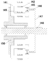
- Figure 17 is a schematic view showing the structure of a double-sided cantilever with a flanged rotor holder and a permanent magnet according to the present invention.
- Figure 18 is a cross-sectional view showing the structure of the double-sided cantilever belt flanged rotor holder and the permanent magnet of the present invention (cross-sectional view taken along line E-E of Figure 17).
- Fig. 19 is a schematic view showing the appearance of a double-sided cantilever belt flanged rotor bracket and a permanent magnet structure according to the present invention.
- Figure 22 is a perspective view showing the structure of a double cantilever with a flanged rotor support motor according to a fourth embodiment of the present invention.
- Figure 21 is a schematic view showing the structure of a double cantilever with a flanged rotor support motor according to a fourth embodiment of the present invention.
- Figure 22 is a cross-sectional view showing the structure of a double cantilever with a flanged rotor holder motor according to a fourth embodiment of the present invention (cross-sectional view taken along line F-F of Figure 21).
- Figure 23 is a schematic view showing the structure of the "U-shaped" single-coil excitation salient pole of the present invention (the magnetic pole port faces face in the same direction).
- Figure 24 is a perspective view showing the structure of a "U-shaped" single-coil excitation salient pole pair of the present invention.
- Figure 25 is a schematic view showing the structure of a disc-shaped rotor holder and a permanent magnet according to a fifth embodiment of the present invention (a permanent magnet is disposed on one side of the disc-shaped rotor holder).
- Fig. 26 is a cross-sectional view showing the structure of a disk-shaped rotor holder and a permanent magnet according to a fifth embodiment of the present invention (cross-sectional view taken along line G-G of Fig. 25).
- Fig. 27 is a perspective view showing the structure of a disk-shaped rotor holder and a permanent magnet according to a fifth embodiment of the present invention.
- Figure 29 is a fifth embodiment of the present invention, a disc-shaped rotor bracket is provided with a permanent magnet electric motor on one side
- Fig. 30 is a cross-sectional view showing the structure of a permanent magnet motor provided on one side of a disk-shaped rotor holder according to a fifth embodiment of the present invention (H-H sectional view of Fig. 29;
- Figure 31 is a schematic view showing the structure of a disk-shaped rotor holder and a permanent magnet according to a sixth embodiment of the present invention.
- the disc-shaped rotor bracket is provided with permanent magnets on both sides).
- Figure 32 is a cross-sectional view showing the structure of a disk-shaped rotor holder and a permanent magnet according to a sixth embodiment of the present invention (cross-sectional view taken along line I-I of Figure 31).
- Figure 33 is a schematic view showing the appearance of a disk-shaped rotor holder and a permanent magnet according to a sixth embodiment of the present invention.
- Fig. 34 is a perspective view showing the structure of a motor of a "U-shaped" single-coil excitation salient pole pair and a disc-shaped rotor holder provided with permanent magnets on both sides of the present invention.
- Figure 35 is a schematic view showing the structure of a motor of a sixth embodiment of the present invention.
- Figure 36 is a cross-sectional view showing the structure of a motor according to a sixth embodiment of the present invention (cross-sectional view taken along line J-J of Figure 35).
- Figure 37 is a schematic view showing the structure of the excitation salient pole pair of the "U-shaped" double-coil series excitation of the present invention (the magnetic pole port faces face in the same direction, and the L1 coil forwardly enters the excitation current).
- Figure 38 is a schematic view showing the structure of the excitation salient pole pair of the "U-shaped" double-coil series excitation of the present invention (the magnetic pole port faces face in the same direction, and the L2 coil reversely enters the excitation current)
- 39 is a schematic structural view of a switched reluctance motor in which a "U-shaped" double-coil series excitation excitation salient pole pair and a disc-shaped rotor bracket are provided with a permanent magnet on one side of the embodiment of the present invention.
- Figure 40 is a cross-sectional view showing the structure of a motor of the seventh embodiment of the present invention (cross-sectional view taken along line K-K of Figure 3941).
- Figure 41 is a schematic view showing the structure of a seventh embodiment of the present invention.
- Figure 42 is a schematic view showing the appearance of a single-coil excited composite excitation salient pole of the present invention (the magnetic pole port is face-to-face opposite).
- 43 is a schematic view showing the structure of a "C-shaped" laminated core and an exciting coil of a single-coil excited composite excitation salient pole according to the present invention.
- Figure 44 is a schematic view showing the structure of a single cantilever rotor holder and a permanent magnet of the present invention.
- Figure 45 is a cross-sectional view showing the structure of a single cantilever rotor holder and a permanent magnet of the present invention (cross-sectional view taken along line A-A of Figure 44).
- Figure 46 is a perspective view showing the structure of a single cantilever rotor holder and a permanent magnet of the present invention.
- Figure 47 is a perspective view showing the structure of a single cantilever unipolar permanent magnet multi-effect reluctance motor according to a ninth embodiment of the present invention.
- FIG. 48 is a schematic structural view of a single cantilever unipolar permanent magnet synergistic reluctance motor according to Embodiment 9 of the present invention.
- Figure 49 is a cross-sectional view showing the structure of a single cantilever unipolar permanent magnet multi-effect reluctance motor according to a ninth embodiment of the present invention (cross-sectional view taken along line B-B of Figure 48).
- Figure 50 is a schematic view showing the structure of a double cantilever rotor holder and a permanent magnet of the present invention.
- Figure 51 is a cross-sectional view showing the structure of the double cantilever rotor holder and the permanent magnet of the present invention (cross-sectional view taken along line C-C of Figure 50).
- Figure 52 is a perspective view showing the structure of the double cantilever rotor holder and the permanent magnet of the present invention.
- Figure 53 is a perspective view showing the structure of a unipolar permanent magnet multi-effect reluctance motor of a double cantilever rotor support according to a tenth embodiment of the present invention.
- Figure 54 is a structural schematic view showing a unipolar permanent magnet synergistic reluctance motor of a double cantilever rotor support according to a tenth embodiment of the present invention.
- Figure 55 is a cross-sectional view showing the structure of a double-cantilever rotor support unipolar permanent magnet multi-effect reluctance motor according to a tenth embodiment of the present invention (cross-sectional view taken along line D-D of Figure 54).
- Figure 56 is a schematic view showing the structure of the double cantilever rotor support and the permanent magnet misalignment according to the eleventh embodiment of the present invention.
- Fig. 57 is a perspective view showing the structure of a double cantilever rotor holder and a permanent magnet misalignment structure according to an eleventh embodiment of the present invention.
- Figure 58 is a schematic view showing the structure of the double-coil bipolar composite excitation salient pole pair of the present invention (the magnetic pole port is face-to-face opposite).
- Figure 59 is a schematic view showing the structure of a "C-shaped" laminated core and an exciting coil in the double-coil bipolar composite excitation salient pole pair of the present invention.
- Figure 60 is a schematic view showing the structure of a single cantilever bipolar permanent magnet synergistic reluctance motor according to a twelfth embodiment of the present invention.
- Figure 61 is a cross-sectional view showing the structure of a single cantilever bipolar permanent magnet synergistic reluctance motor according to a twelfth embodiment of the present invention (cross-sectional view taken along line E-E of Fig. 60).
- Figure 62 is a perspective view showing the structure of a single cantilever bipolar permanent magnet synergistic reluctance motor according to a twelfth embodiment of the present invention.
- Figure 63 is a perspective view showing the structure of a double cantilever bipolar permanent magnet synergistic reluctance motor according to a thirteenth embodiment of the present invention.
- Figure 64 is a schematic view showing the structure of a single-coil bipolar composite excitation salient pole pair of the present invention, that is, two permanent magnets are embedded in the laminated core core notch (the magnetic pole port face is opposite to the surface).
- Figure 65 is a schematic view showing the structure of a "C-shaped" laminated core, a permanent magnet and an exciting coil of a single-coil bipolar composite excitation salient pole pair according to the present invention.
- Figure 66 is a schematic view showing the structure of a single cantilever bipolar permanent magnet synergistic reluctance motor according to a fourteenth embodiment of the present invention.
- Figure 67 is a cross-sectional view showing the structure of a single cantilever bipolar permanent magnet multi-effect reluctance motor according to a fourteenth embodiment of the present invention (cross-sectional view taken along line F-F of Figure 66)
- Figure 68 is a schematic external view of a single cantilever bipolar permanent magnet synergistic reluctance motor according to a fourteenth embodiment of the present invention.
- 69 is a schematic view showing the structure of a double-coil series-excited unipolar composite excitation salient pole pair structure, in which a permanent magnet is embedded in a laminated core core gap (magnetic pole port face-down)
- Figure 70 is a schematic view showing the structure of a "C-shaped" laminated core, a permanent magnet, and a series double coil in a dual-coil series-excited unipolar composite excitation salient pole pair of the present invention.
- Figure 71 is a schematic view showing the structure of a single-coil excited unipolar composite excitation salient pole pair of the present invention (the magnetic pole port faces face in the same direction).
- Figure 72 is a schematic view showing the structure of a single-coil excited unipolar composite excitation salient pole pair "U-shaped" laminated core and exciting coil of the present invention.
- Figure 73 is a schematic view showing the structure of a disk-shaped rotor holder and a permanent magnet according to a fifteenth embodiment of the present invention.
- Figure 74 is a cross-sectional view showing the structure of a disk-shaped rotor holder and a permanent magnet according to a fifteenth embodiment of the present invention (cross-sectional view taken along line G-G of Figure 73).
- Figure 75 is a perspective view showing the appearance of a disk-shaped rotor holder and a permanent magnet according to a fifteenth embodiment of the present invention.
- Figure 76 is a perspective view showing the structure of a unipolar permanent magnet synergistic reluctance motor in which a permanent magnet is arranged on one side of a disk-shaped rotor holder according to a fifteenth embodiment of the present invention.
- Fig. 77 is a structural schematic view showing a unipolar permanent magnet synergistic reluctance motor in which a permanent magnet is arranged on one side of a disk-shaped rotor holder according to a fifteenth embodiment of the present invention.
- FIG. 78 is a unipolar permanent body in which a permanent magnet is arranged on one side of a disk-shaped rotor holder according to a fifteenth embodiment of the present invention.
- a cross-sectional view of the structure of the magnetic synergistic reluctance motor cross-sectional view in the H-H direction of Fig. 77).
- Figure 79 is a schematic view showing the structure of a disk-shaped rotor holder and a permanent magnet according to a sixteenth embodiment of the present invention.
- Figure 80 is a cross-sectional view showing the structure of a disk-shaped rotor holder and a permanent magnet according to a sixteenth embodiment of the present invention (cross-sectional view taken along line I-I of Figure 79).
- Figure 81 is a perspective view showing the appearance of a disk-shaped rotor holder and a permanent magnet according to a sixteenth embodiment of the present invention.
- FIG. 82 is a schematic view showing the appearance of a unipolar permanent magnet synergistic reluctance motor provided with permanent magnets on both sides of a disk-shaped rotor holder according to Embodiment 17 of the present invention.
- Figure 83 is a structural schematic view of a unipolar permanent magnet synergistic reluctance motor in which a permanent magnet is disposed on both sides of a disk-shaped rotor holder according to a seventeenth embodiment of the present invention.
- Figure 84 is a cross-sectional view showing the structure of a unipolar permanent magnet synergistic reluctance motor in which a permanent magnet is disposed on both sides of a disk-shaped rotor holder according to a seventeenth embodiment of the present invention (cross-sectional view taken along line J-J of Fig. 83).
- Fig. 85 is a schematic view showing a polarity state of the composite excitation of the double-coil excited bipolar composite excitation salient pole according to the present invention (the magnetic pole port faces face in the same direction).
- Figure 86 is a schematic view showing another polarity state of the composite excitation by the two-coil excited bipolar excitation salient pole of the present invention.
- 87 is a structural schematic view of a bipolar permanent magnet synergistic reluctance motor in which a permanent magnet is disposed on one side of a disk-shaped rotor support according to an eighteenth embodiment of the present invention.
- Figure 88 is a cross-sectional view showing the structure of a bipolar permanent magnet synergistic reluctance motor in which a permanent magnet is disposed on one side of a disk-shaped rotor holder according to an eighteenth embodiment of the present invention (Fig. 87 is a cross-sectional view taken along the line K-K).
- 89 is a schematic view showing the appearance of a bipolar permanent magnet synergistic reluctance motor provided with permanent magnets on one side of a disk-shaped rotor support according to an eighteenth embodiment of the present invention.
- Figure 90 is a perspective view showing the structure of a bipolar permanent magnet synergistic reluctance motor in which a permanent magnet is disposed on both sides of a disk-shaped rotor holder according to a nineteenth embodiment of the present invention.
- Figure 91 is a structural schematic view showing a bipolar permanent magnet synergistic reluctance motor in which a permanent magnet is disposed on both sides of a disk-shaped rotor holder according to a nineteenth embodiment of the present invention.
- Figure 92 is a cross-sectional view showing the structure of a bipolar permanent magnet synergistic reluctance motor in which a permanent magnet is disposed on both sides of a disk-shaped rotor holder according to a nineteenth embodiment of the present invention (Fig. 91 is a cross-sectional view taken along the line L-L).
- 11 is a "C-shaped" laminated core
- 12 is an exciting coil
- 13 is a permanent magnet
- 14 is a cylinder
- 15 is a disk
- 16 is a rotating shaft
- 17 is a stator seat
- 18 is a bearing.
- 21a is a "C-shaped" laminated piece Iron core
- 21b is a "C-shaped” laminated core
- 22a is an excitation coil
- 22b is an excitation coil
- 23a is a permanent magnet
- 23b is a permanent magnet
- 24 is a cylinder
- 25 is a disc
- 26 is a rotating shaft
- 27 Is a stator seat
- 28 is a bearing
- 33a is a permanent magnet
- 33b is a permanent magnet
- 34 is a cylinder
- 35 is a disc
- 36 is a rotating shaft
- 41a is a "C-shaped” laminated core
- 41b is a "C-shaped” Laminated core
- 42a is the excitation coil
- 42b is the excitation coil
- 43a is the permanent magnet
- 43b is the permanent magnet
- 44 is the cylinder with the hem
- 45 is the disc
- 46 is the rotating shaft
- 47 is the stator seat
- 48 Is a bearing
- 111 is a "C-shaped" laminated core
- 112 is an exciting coil
- 113 is a permanent magnet
- 114 is a cylinder
- 115 is a disk
- 116 is a rotating shaft
- 117 is a stator seat
- 118 is a bearing.
- 119 is a permanent magnet
- 120 is a magnetizer
- 123a is a permanent magnet
- 123b is a permanent magnet
- 124b is a permanent magnet
- 124 is a cylinder
- 125 is a disc
- 126 is a rotating shaft
- 127 is a stator seat
- 128 is a bearing
- 129a is a permanent magnet
- 129b Is a permanent magnet
- 130a is a magnetizer
- 130b is a magnetizer
- 133a is a permanent magnet
- 133b is a permanent magnet
- 133b is a permanent magnet
- 134 is a cylinder
- 135 is a disc
- 136 is a rotating shaft
- 141 is a "C-shaped" laminated core.
- 142 is an excitation coil
- 143 is a magnetizer
- 144 is a permanent magnet
- 144 is a permanent magnet
- 145 is a permanent magnet
- 146 is a cylinder
- 147 is a disc
- 148 is a rotating shaft
- 149 is an exciting coil
- 150 is a stator seat
- 151 is a C-shaped "Laminated core
- 152 is the excitation coil
- 153 is the permanent magnet
- 154 is the gap between the permanent magnet and the laminated core
- 155 is the permanent magnet
- 156 is the cylinder
- 157 is the disc
- 158 is the rotating shaft
- 159 is a bearing
- 160 is a stator seat
- 161 is a "C-shaped" laminated core
- 162 is an exciting coil
- 163 is a permanent magnet
- 164 is a permanent magnet and a laminated core.
- the gap, 165 is the excitation coil
- 171 is the "U-shaped" laminated core
- 172 is the excitation coil
- 173 is the permanent magnet
- 174 is the magnetizer
- 175 is the permanent magnet
- 176 is the permanent magnet
- 177 is the disc
- 178 It is a rotating shaft
- 179 is a bearing
- 180 is a stator seat
- 181a is a "U-shaped” laminated core
- 181b is a "U-shaped” laminated core
- 182a is an exciting coil
- 182b is an exciting coil
- 185a is a permanent magnet.
- 185b is a permanent magnet
- 186a is a permanent magnet
- 186b is a permanent magnet
- 186b is a permanent magnet
- 187 is a stator seat
- 188 is a rotating shaft
- 191 is a "U-shaped" laminated core
- 192 is an exciting coil
- 193 is a permanent magnet
- 194 is a magnetizer.
- 195 is a permanent magnet
- 196 is a permanent magnet
- 197 is a disc
- 198 is a rotating shaft
- 199 is a stator seat
- 201a is a "U-shaped” laminated core
- 201b is a "U-shaped laminated iron”
- the core 202a is an exciting coil
- 202b is an exciting coil
- 205a is a permanent magnet
- 205b is a permanent magnet
- 206a is a permanent magnet
- 206b is a permanent magnet
- 207 is a circular disc
- 208 is a rotating shaft
- 209 is a stator seat.
- Embodiment 1 is a diagrammatic representation of Embodiment 1:
- an AC permanent magnet switched reluctance motor is provided which is provided with a "C-shaped" single-coil excitation salient pole pair and a rotor is composed of a single-sided cantilever bracket, and its structure and outer shape are as shown in FIG. 6-8.
- the stator of the embodiment is composed of a stator base 17 and four "C-shaped” excitation salient pole pairs, and four "C-shaped” excitation salient pole pairs are respectively arranged on the upper, lower, left and right sides, and there are ninety-corner centers between each other. The gap between the corners.
- the "C-shaped” field salient pole pair is composed of a "C-shaped” laminated core 11 and an exciting coil 12, and the exciting coil 12 is wound around the middle periphery of the laminated core 11, as shown in Fig. 1, "C-shaped” stack
- the two ports of the core are opposite on the surface, and the two port faces are curved.
- the magnetic polarity N is immediately present at the upper port surface of the "C-shaped" excitation salient pole pair.
- the magnetic pole S is immediately present at the lower port face of the "C-shaped" excitation salient pole pair, as shown in Fig. 2, when the excitation coil inputs a negative excitation current, at the upper port face of the "C-shaped” excitation salient pole pair
- the magnetic polarity S is immediately present while the magnetic pole N is immediately present at the lower port face of the "C-shaped” field salient pole pair.
- the rotor of this embodiment is composed of a rotating shaft 16 and a single-sided cantilever rotor support.
- the single-sided cantilever rotor support is composed of a disk 15 and a cylinder 14.
- the center of the disk 15 is fixed integrally with the rotating shaft 16, and the disk 15 is perpendicular to the plane.
- the axis of the cylinder 14 coincides with the axis of the rotating shaft, and one end edge of the cylinder 14 is fixedly coupled with the circular disk 15 to form a one-side cantilever structure rotor support, and the other end edge of the cylinder 14 is fixed at equal intervals.
- the action mechanism and the drive control mode of the embodiment are: when the forward excitation current is applied to the excitation coil 12 of the "C-shaped" excitation salient pole pair above the stator, the upper port surface of the "C-shaped” excitation salient pole pair is presented. N pole magnetism, the lower port surface exhibits S pole magnetism, and the "C-shaped” field salient pole pair generates magnetic attraction force to the permanent magnet 13 having the outer cross section magnetic polarity S on the rotor cantilever and the inner cross section magnetic polarity N.
- the "C-shaped" excitation salient pole pair will also have a magnetic polarity of N on the outer section of the rotor cantilever and a magnetic polarity of the inner section.
- the "C-shaped” excitation salient pole forms a rotational moment on the rotor under the action mechanism of "attracting the rear permanent magnet and repelling the front permanent magnet", when attracted to the permanent
- the excitation magnetic potential of the "C-shaped” excitation salient pole pair passes through the air gap above the permanent magnet, and the permanent magnet 13.
- the air gap of the arc surface below the permanent magnet forms a closed magnetic circuit with a relatively small magnetic reluctance.
- the motor drive control device immediately Changing the excitation current direction of the "C-shaped” excitation salient pole to the excitation coil, and introducing a negative excitation current, so that the magnetic polarity of the "C-shaped” excitation salient pole changes to the upper and lower port faces, that is, the upper port surface exhibits an S pole Magnetically, the lower port surface exhibits N-pole magnetism.
- the "C-shaped" excitation salient pole pair will continue to repeat the action of "sucking and pushing forward".
- the six permanent magnets on the rotor cantilever bracket have two "C-shaped” excitation convexs for every 30 degree central angle of rotation of the rotating shaft.
- the pole pair is aligned with two permanent magnets, that is, the permanent magnet is located between the upper and lower port faces of the "C-shaped" field salient pole pair, thereby achieving continuous torque output of the rotor.
- the rotor bracket of the motor of the embodiment adopts a single-side cantilever structure, which greatly compresses the axial dimension of the conventional switched reluctance motor.
- the unique drive control mode of the embodiment effectively eliminates the negative of the conventional switched reluctance motor. Torque, the performance of the motor is further improved.
- Embodiment 2 is a diagrammatic representation of Embodiment 1:
- an AC permanent magnet switched reluctance motor is provided which is provided with a "C-shaped" single-coil excitation salient pole pair and a rotor composed of a double-sided cantilever bracket.
- the outer shape and structure are as shown in FIGS. 12-14.
- the rotor of this embodiment is composed of a rotating shaft 26 and a double-sided cantilever rotor support.
- the double-sided cantilever rotor support is composed of a disk 25 and a cylinder 24.
- the center of the disk 25 is fixed integrally with the rotating shaft, and the disk 25 is perpendicular to the surface.
- the axis of the cylinder 25 coincides with the axis of the rotating shaft 26, and the one-half position of the cylinder 24 is fixedly connected with the disk 25 to form a double-sided cantilever structure rotor bracket, and the two ends of the cylinder 24 are respectively respectively waited
- Six permanent magnets are fixed at intervals, and the permanent magnets at both ends of the cylinder 24 are symmetrical with the disk 25, that is, the permanent magnet 23a of the left end edge of the cylinder 24 and the permanent magnet 23b of the right end edge of the cylinder 24 are symmetric with the disk 25.
- the magnetic polarity of the permanent magnet is set as shown in Fig. 11.
- the central angle between the radial centerlines of each permanent magnet differs by sixty degrees, and the magnetic polarities of two adjacent permanent magnets are different.
- the arc of the two pole faces is identical to the arc of the two port faces of the "C-shaped" field salient pole pair.
- the structural features of the "C-shaped" excitation salient poles on the stator are the same as those in the first embodiment.
- the stator "C-shaped" excitation salient pole pairs of the present embodiment are eight, four are a group, and the rotor discs 24 are symmetrically arranged in groups, as shown in FIG. 13 and FIG.
- the "C-shaped" excitation salient poles on both sides of the rotor support are identical to the interaction mechanism of the permanent magnets on the rotor.
- the "C-shaped” excitation salient poles on both sides of the rotor support are also fully synchronized with the commutation timing of the excitation current in the excitation coil. The effect is similar to the connection of the rotating shafts of the motors of the two embodiments.
- the rotor of the embodiment adopts a double cantilever bracket structure, the dynamic balance is enhanced, the output torque is increased, and the axial dimension of the motor is limited.
- Embodiment 3 is a diagrammatic representation of Embodiment 3
- another AC permanent magnet switched reluctance motor is provided which is provided with a "C-shaped" single-coil excitation salient pole pair and a rotor is composed of a double-sided cantilever bracket, and a "C-shaped” excitation salient pole pair on the stator"
- the structure and setting position are the same as those in the second embodiment, and can be seen in the accompanying drawings 13-14.
- the rotor of this embodiment is composed of a rotating shaft 36 and a double-sided cantilever rotor support.
- the double-sided cantilever rotor support is composed of a disk 35 and a cylinder 34.
- the center of the disk 35 is fixed integrally with the rotating shaft 36, and the disk surface is perpendicular to Rotating the axis of the shaft 36, the axis of the cylinder 34 coincides with the axis of the rotating shaft 36, and one-half of the position of the cylinder 34 is fixedly connected with the disk to form a double-sided cantilever structure rotor support, and the two ends of the cylinder 34 are equally spaced
- There are six permanent magnets fixed the central angle difference between the radial centerlines of the six permanent magnets is sixty degrees, and the magnetic polarities of the adjacent two permanent magnets are different, and the six left edges of the cylinder 34 are set for six permanent
- the magnet is offset from the six permanent magnets disposed at the right end edge of the cylinder by an angle of thirty
- the two ends of the double-sided cantilever bracket are provided with permanent magnets at a 30-degree central angle of the misalignment, so that the "C-shaped" excitation salient poles disposed on opposite sides of the rotor support are reversing the electric excitation current in the excitation coil.
- the timing is also staggered, so that the motor of the present embodiment has a smaller step angle, thereby further improving the smoothness of the rotor rotation.
- Embodiment 4 is a diagrammatic representation of Embodiment 4:
- another AC permanent magnet switched reluctance motor is provided, which is provided with a "C-shaped" single-coil excitation salient pole pair and a rotor composed of a double-sided cantilever bracket.
- the outer shape and structure are as shown in Figs. 20-22. .
- the "C-shaped" field salient pole pair on the stator in this embodiment is the same as the first embodiment, as shown in FIG. 1 and FIG. 2.
- the eight "C-shaped" excitation salient pole pairs are divided into two groups, which are respectively disposed on both sides of the rotor support disc and are evenly arranged on the stator base, as shown in FIG. 22, all "C-shaped”
- the excitation salient pole pair lamination core 41a and the "C-shaped” excitation salient pole face the left and right sides of the two magnetic port faces of the laminated core 41b.
- the rotor holder is composed of a disk 45 and a flanged cylinder 44.
- the inner wall of the central portion of the flanged cylinder 44 is fixedly connected to the outer edge of the disk 45 to form a
- the center of the disc 45 is fixedly connected with the rotating shaft 46.
- the plane of the disc 45 is perpendicular to the axis of the rotating shaft 46, and the axis of the flanged cylinder 44 coincides with the axis of the rotating shaft 46.
- the hemming surface of the hemming cylinder 44 is perpendicular to the axis of the rotating shaft 46, and the twelve permanent magnets are divided into two groups, which are symmetrically fixed symmetrically at the flanges at both ends of the flanged cylinder, and are on the same rotating surface.
- the magnetic polarities of two adjacent permanent magnets are different, as shown in FIG.
- Embodiment 5 is a diagrammatic representation of Embodiment 5:
- a switched reluctance motor which is provided with a "U-shaped" single-coil excitation salient pole pair and a permanent magnet body on one side of the rotor support disc, and its structure and outer shape are as shown in FIGS. 28-30.
- the stator of the embodiment is composed of a stator seat and four "U-shaped” excitation salient pole pairs, and four "U-shaped” excitation salient pole pairs are respectively arranged on the upper, lower, left and right sides, and there are ninety-corner central angles between each other. difference.
- Each "U-shaped" field salient pole pair is comprised of a "U-shaped” laminated core 51, a set of exciting coils 52, as shown in Figures 23 and 24, the "U-shaped” laminated core 51.
- the two salient pole ports face in the same direction.
- the rotor support of this embodiment is a disc 55.
- the twelve permanent magnets are symmetrical axes with the axis of the rotating shaft, and the inner and outer rings are disposed on one side of the magnetic conductive disc 55, and the inner permanent magnets are spaced apart from each other. Equally, the outer ring permanent magnets are equally spaced from each other. As shown in FIG. 25 and FIG. 27, since the disk 55 is magnetically guided, the inner ring permanent magnet 54 and the outer ring permanent magnet are disposed on the same line.
- each pair of permanent magnet salient poles on the side of the disc sequentially sweeps through the respective excitations on the stator.
- Magnetic salient pole pairs, and the port faces of the pairs of permanent magnet salient poles and the respective excitation salient poles form an air gap between the port faces, when any one of the permanent magnet salient poles on the rotor pairs the two port faces and any one of the excitation protrusions on the stator
- a shortest magnetic circuit is formed between the pair of permanent magnet salient poles and the pair of excitation salient poles.
- a switched reluctance motor which is provided with a "U-shaped" single-coil excitation salient pole pair and a permanent magnet body on both sides of the rotor support disc, and its appearance and structure are as shown in FIG. 34-36. .
- the stator of the present embodiment is composed of a stator base and eight "U-shaped" excitation salient pole pairs. As shown in Fig. 34 and Fig. 36, eight "U-shaped" excitation salient pole pairs are divided into two groups, which are respectively placed in the rotor. On both sides of the bracket disc, each set of four "U-shaped" excitation salient pole pairs are respectively arranged on the upper, lower, left and right sides, and there is a gap of 90 degree angles between the two.
- the rotor support of the embodiment is a disc 65.
- the twenty-four permanent magnets are symmetrical axes with the axis of the rotating shaft 66.
- the inner and outer rings are disposed on two sides of the magnetic conductive disc 65, and the inner ring permanent magnets are mutually The intervals are equal, and the outer ring permanent magnets are equally spaced from each other. Since the disk 65 is magnetically guided, the inner ring permanent magnet 64a and the outer ring permanent magnet 63a disposed on the same line form a permanent magnet salient pole pair.
- six permanent magnet salient pole pairs are formed on one side of the magnetic conductive disc 65, and the magnetic polarities of the adjacent two permanent magnet salient pole pairs are different, as shown in FIG.
- the distance between each of the permanent magnet salient poles and the salient poles is the same as the distance between the stator excitation salient poles and the salient poles of the laminated core.
- each pair of permanent magnet salient poles on both sides of the disc 65 sequentially sweeps each pair of excitation salient poles on the stator, and the port faces of the pairs of the permanent magnet salient poles and the respective excitation salient poles face the port surface Forming an air gap therebetween, when any one of the permanent magnet salient poles on the rotor pairs the two port faces and any one of the excitation salient poles on the stator to face each other, the permanent magnet salient pole pairs and the excitation salient poles A shortest magnetic circuit is formed.
- the "U-shaped" excitation salient poles on both sides of the rotor support disc of the present embodiment are identical to the interaction mechanism and the timing of the permanent magnet salient pole pairs on both sides of the disc, and the U-shape on both sides of the rotor support disc "The excitation timing of the exciting current in the excitation coil is also completely synchronized. The effect is similar to the two motor shafts of the fifth embodiment. The dynamic balance is enhanced and the output torque is increased. The axial dimension of the motor is The increase is limited.
- the permanent magnet salient poles on both sides of the rotor support disk 65 can be shifted from each other to the radial center line.
- the thirty-degree central angle setting that is, the radial centerline of the six permanent magnet salient pole pairs on the left side of the rotor bracket disc and the radial centerline of the six permanent magnet salient pole pairs on the right side of the rotor bracket disc are thirty.
- the degree of center angle dislocation makes the motor of the embodiment have a smaller step angle, thereby further improving the smoothness of the rotation of the rotor.
- a switched reluctance motor which is provided with a "U-shaped" double-coil excitation salient pole pair and a permanent magnet body is arranged on one side of the rotor support disc, and its structure and outer shape are as shown in FIG. 39-41.
- the stator of the embodiment is composed of a stator seat and four "U-shaped” excitation salient pole pairs, and four "U-shaped” excitation salient pole pairs are respectively arranged on the upper, lower, left and right sides, and there are ninety-corner central angles between each other. difference.
- each "U-shaped" field salient pole pair is composed of a "U-shaped” laminated core 71, two sets of exciting coils 72, and the exciting coils L1 and L2 are wound respectively.
- the upper and lower frames of the U-shaped laminated core, the exciting coils L1 and L2 are connected in series, and the port faces of the two salient poles of the "U-shaped" laminated core face in the same direction.
- the rotor support of this embodiment is a disc 75.
- the twelve permanent magnets are symmetrical axes with the axis of the rotating shaft 76, and the inner and outer rings are disposed on one side of the magnetic conductive disc 75, and the inner ring permanent magnets are mutually The intervals are equal, and the outer ring permanent magnets are equally spaced from each other.
- the inner ring permanent magnet 74 and the outer ring permanent magnet 73 disposed on the same line form a permanent magnet salient pole pair, adjacent
- the magnetic polarities of the two permanent magnet salient pole pairs are different, as shown in FIG. 25 and FIG. 27, the distance between each salient pole of the permanent magnet salient pole and the salient pole of the stator "U-shaped" excitation salient pole The distance between the poles is the same.
- each pair of permanent magnet salient poles on the side of the disc 75 sequentially sweeps through the respective "U-shaped" exciting salient pole pairs on the stator, and the port faces of the respective permanent magnet salient pole pairs and the respective excitation salient pole pairs An air gap is formed between the port faces.
- the permanent magnet salient pole pair and the excitation convex A shortest magnetic circuit is formed between the pole pairs.
- the excitation salient pole of the embodiment has a shape of a laminated core of "U-shaped", The two port faces face in the same direction, and the other difference is that in this embodiment, the excitation currents in different directions are respectively input into the series excitation coils L1 and L2 to change the magnetic polarity of the excitation salient pole to the port surface, and the embodiment First, the magnetic polarity of the excitation salient pole to the port surface is changed by changing the direction of the excitation current of the same excitation coil.
- a switched reluctance motor which is provided with a "U-shaped" double-coil excitation salient pole pair on the stator and a permanent magnet on both sides of the rotor support disc.
- the structure of this embodiment is similar to that of the sixth embodiment, except that a "U-shaped" double-coil excitation salient pole pair is disposed on the stator.
- the change in the magnetic polarity of the "U-shaped" double-coil excitation salient pole pair provided on the stator of the present embodiment is achieved by alternately applying excitation currents to the coils L1 and L2, as shown in Figs. 37 and 38.
- the number of pairs of excitation salient poles on the stator is four, and the number of pairs of permanent magnets or permanent magnets on the rotor is six, but
- the technical solution of the present invention is not limited to the relationship between the number of the stator excitation salient poles and the number of rotor permanent magnets or permanent magnet salient poles. According to the actual size of the motor and the rated power, a plurality of proportional relationship selections can be made.
- the number of excitation salient pole pairs on the stator is N
- the number of permanent magnets or "permanent magnet salient pole pairs" on the rotor is M
- N is a natural number greater than or equal to 2
- k is an even number
- k takes a natural number
- the ratio of M/N is not a positive integer.
- the motor of the above-mentioned second, third, fourth and sixth embodiments of the present invention is a symmetric coupling structure of the first, fifth and seventh embodiments, so that the stator excitation salient pole pair and the rotor permanent magnet or permanent magnet salient pole pair are also followed.
- the law of quantity is a symmetric coupling structure of the first, fifth and seventh embodiments.
- a unipolar permanent magnet synergistic reluctance motor using a single-sided cantilever bracket and a composite excitation salient pole pair is shown in the embodiment, and its structure and shape are as shown in FIGS. 47-49.
- the stator of the embodiment is composed of a stator base 117 and four "composite excitation salient pole pairs", and four “composite excitations”
- the magnetic salient pole pairs are respectively disposed on the upper, lower, left and right sides, and there is a gap of 90 degree centroids between each other.
- the "composite excitation salient pole pair” consists of a "C-shaped” laminated core 111, an exciting coil 112 and a permanent magnet.
- the components 119, 120 are constructed. As shown in Fig. 43, the two ports of the "C-shaped laminated core" are face-to-face opposite, and the two port faces are curved.
- the rotor of this embodiment is composed of a rotating shaft and a single-sided cantilever rotor support.
- the single-sided cantilever rotor support is further composed of a disk 115 and a cylinder 114, as shown in Figs. 44-46, forming a "single-mouth bowl" rotor bracket.
- the center of the disc is fixed integrally with the rotating shaft 116.
- the disc surface is perpendicular to the rotation axis, the axis of the cylinder coincides with the axis of the rotating shaft, and one end edge of the cylinder is fixedly connected with the disc to form a single-sided cantilever structure rotor bracket.
- the other end edge of the cylinder is fixed with six permanent magnets 113 at equal intervals, and the magnetic polarity of the permanent magnets is set as shown in Fig. 44, and there is a difference of 60 degree center angle between the radial center lines of each permanent magnet. And the magnetic polarities of the two adjacent permanent magnets are different, and the arc of the two magnetic pole faces of each permanent magnet is the same as the arc of the two-port surface of the "C-shaped" laminated core of the composite excitation salient pole pair, and is fixed when the rotating shaft rotates.
- the permanent magnets at the end of the rotor support can sequentially pass between the ports of the respective pairs of composite excitation salient poles on the stator, and there is a gap between the two magnetic pole faces of each permanent magnet and the two port faces of the respective "C-shaped" laminated cores. The same air gap.
- the driving mechanism of this embodiment is that when the excitation current is applied to the excitation coil of the pair of composite excitation salient poles above the stator, the upper port surface of the "C"-shaped laminated core 111 of the pair of composite excitation salient poles exhibits N-pole magnetic properties. The lower port surface exhibits S pole magnetism. At this moment, the magnetic potential of the upper and lower port faces of the "C-shaped" laminated core is the excitation flux of the excitation coil of the composite excitation salient pole and the permanent magnet assembly. Composite superposition of magnetic flux.
- the composite excitation salient pole pair generates magnetic attraction force to the permanent magnet 113 having the outer cross-section magnetic polarity S on the rotor cantilever and the inner cross-section magnetic polarity N, and the rotational torque formed on the rotor is S, when the outer cross-section magnetic polarity is S,
- the permanent magnet 113 having the inner side magnetic polarity N is located between the upper and lower port faces of the "C-shaped" laminated core of the pair of composite exciting salient poles, as shown in FIG. 49, the composite of the composite excitation salient pole pairs
- the magnetic flux forms a magnetoresistance through the air gap above the permanent magnet, the permanent magnet, and the air gap under the arc of the permanent magnet. A relatively small closed magnetic circuit.
- the motor driving device interrupts the excitation current of the composite excitation salient pole to the excitation coil, so that the composite excitation salient pole pair
- the magnetic polarity of the upper and lower port faces of the C-shaped laminated core disappears.
- the permanent magnet between the composite excitation salient poles and the "C-shaped" laminated core port is no longer subjected to the magnetic attraction of the composite excitation salient pole pair. To avoid the formation of negative torque.
- the permanent magnet When the outer surface magnetic pole has a magnetic polarity of N and the inner cross section has a magnetic polarity S, the permanent magnet is transferred between the composite excitation salient pole and the "C" laminated core port, because the composite excitation salient pole is in the excitation coil The excitation current is zero, the composite excitation salient pole does not generate a repulsive force thereto, and the negative torque is also avoided.
- the outer cross section has a magnetic polarity N and the inner cross section has a magnetic polarity S
- the permanent magnet deviates from the composite excitation convex.
- the motor driving device immediately inputs the exciting current to the exciting coil to the exciting coil, so that the composite exciting salient poles "C-shaped” laminated core
- the composite excitation magnetic potential is re-formed between the ports. Since the magnetic polarity of the port on the "C"-shaped laminated core is N and the magnetic polarity of the lower port is S, the “same-sex repellent" of the permanent magnet just deviating from the aligned position is formed.
- the magnetic repulsive force at the same time, the composite excitation salient pole pair also forms a magnetic attraction force to the rotating permanent magnets.
- the excitation coils of the respective composite excitation salient pole pairs are also independent, so the above-mentioned action of the composite excitation salient pole pair and the permanent magnet on the rotor and The mechanism of action applies to any other composite excitation salient pole pair on the stator.
- the motor drive device controls the on-off of the excitation coil current by the composite excitation salient poles on the stator in real time, so that each composite excitation salient pole pair is always in the work state of “before suction and push”.
- the six permanent magnets on the rotor cantilever bracket have two composite excitation salient pole pairs and the rotor bracket for every 30 degree central angle of rotation of the rotating shaft.
- the two permanent magnets are aligned, that is, the permanent magnets are located between the upper and lower port faces of the composite excitation salient pole pair, thereby achieving continuous rotation of the rotor, and the motor rotating shaft outputs continuous torque.
- the motor ingeniously merges the permanent magnet energy inherent in the permanent magnet assembly into the two-port surface of the "C-shaped" laminated core of the excitation salient pole, so that the magnetic energy of the permanent magnet can also participate in the permanent magnet on the rotor. During the work process, the motor energy efficiency is further improved.
- This embodiment provides a permanent magnet synergistic reluctance motor in which the rotor is a double-sided cantilever bracket and the stator composite excitation salient pole pair is unipolar, and its outer shape and structure are as shown in FIGS. 53-55.
- This embodiment is a special case of the ninth embodiment, that is, the coupling of the motors of the two embodiments is given. Structure.
- a double-sided cantilever rotor support is used, and the structure thereof is as shown in FIG. 50-52.
- the magnetic poles of adjacent permanent magnets on the same side of the bracket and on the same rotating surface are different, and are located on both sides of the bracket and at the same central angle.
- the two permanent magnets in position have the same magnetic polarity.
- the eight composite excitation salient pole pairs of the motor stator are divided into two groups, and the discs in the rotor bracket are symmetric surfaces, and are located on the left and right sides of the disc, and are completely symmetrical and balanced.
- This embodiment improves the output power of the motor and correspondingly increases the synergistic effect of the magnetic energy of the permanent magnet.
- another type of permanent magnet synergistic reluctance motor having a double-sided cantilever bracket and a stator composite excitation salient pole pair is unipolar, and the structure and arrangement position of the composite excitation salient pole pair on the stator are the same as the embodiment.
- Ten see Figures 54-55).
- the difference between this embodiment and the tenth embodiment is that the arrangement rules of the permanent magnets on the double-sided cantilever bracket are different.
- the radial centerlines of the six permanent magnets on one side of the cantilever bracket are mutually There is still a difference of sixty degrees of central angle, and the magnetic polarities of two adjacent permanent magnets are different, but the six permanent magnets at one end of the cantilever bracket are not at the same central angular position as the six permanent magnets at the other end of the cantilever bracket.
- the ⁇ center angle is shifted from each other.
- the radial center line of the permanent magnet 133a and the radial center line of the permanent magnet 133b are misaligned by a central angle of thirty degrees.
- the permanent magnets at both ends of the rotor cantilever bracket are offset by thirty degrees, the permanent magnets on the rotor cantilever bracket are aligned with the composite excitation salient pole pairs on the stator for every 15 degrees of rotation of the rotating shaft 136, and the stator
- the working process and the action mechanism of each of the composite excitation salient pole pairs and the respective permanent magnets on the rotor and the control method of the motor driving device are the same as those in the ninth embodiment, and the description thereof will not be repeated here.
- the permanent magnets are disposed at the opposite ends of the double-sided suspension wall bracket at a 30-degree central angle, so that the commutation timing of the electric excitation current in the excitation coil of the pair of composite excitation salient poles on the left and right sides of the rotor bracket is also staggered.
- the present embodiment provides a permanent magnet synergistic reluctance motor in which the rotor is a single-sided cantilever bracket and the stator composite excitation salient pole pair is a double-coil excited bipolar, and its outer shape and structure are as shown in FIGS. 60-62.
- the stator of the present embodiment is composed of a stator base 150 and four "composite excitation salient pole pairs", and four “composite excitation salient pole pairs” are respectively disposed on the upper, lower, left and right sides, and there is a gap of 90 degree central angle between each other.
- Each composite excitation salient pole pair is comprised of a "C-shaped" laminated core 141, two sets of field coils 142 and two permanent magnet assemblies 143, 144, as shown in Figures 58 and 59, which are "C-shaped"
- the two salient poles of the laminated core are opposite each other on the face and the two port faces are curved.
- the two sets of excitation coils are respectively wound around two parallel frames of the "C-shaped" laminated core, and the magnetic poles S and the magnetic poles N of the two permanent magnet assemblies respectively span the two sets of exciting coils, and the magnetic poles S of the two permanent magnet assemblies
- the magnetic pole N is in close contact with the "C-shaped" laminated core stack section.
- the rotor of this embodiment is composed of a rotating shaft and a single-sided cantilever rotor support.
- the magnetic polarity of the permanent magnets is set as shown in Figure 44, and there are six between the radial centerlines of each permanent magnet.
- the difference between the ten-degree central angle and the magnetic polarity of the adjacent two permanent magnets is the same, and the curvature of the two magnetic pole faces of each permanent magnet is the same as the arc of the two-port surface of the "C-shaped" laminated core of the composite excitation salient pole pair.
- the permanent magnets fixed at the end of the rotor bracket can sequentially pass between the ports of the respective pairs of composite excitation salient poles on the stator, and the two magnetic pole faces of the permanent magnets and the "C-shaped" laminated cores of the respective permanent magnets There is an air gap between the two port faces Gap.
- the driving mechanism of this embodiment is that when the exciting current is applied to the exciting coil L1 and the exciting coil L2 of the pair of composite exciting salient poles in turn, the upper and lower ports of the "C-shaped" laminated core of the composite exciting salient pole pair The magnetic polarity of the surface changes to form a bipolar composite excitation salient pole pair.
- the excitation coil L1 inputs the excitation current
- the upper port surface of the "C-shaped" laminated core of the composite excitation salient pole exhibits a composite N-pole magnetic potential
- the lower port surface exhibits a composite S-pole magnetic potential, as shown in FIG.
- the composite excitation salient pole pair generates a magnetic attraction force to the permanent magnet 145 having the outer cross-section magnetic polarity S on the rotor cantilever and the inner cross-section magnetic polarity N
- the composite excitation salient pole pair can also be the cantilever of the rotor
- the upper side magnetic pole has a magnetic polarity of N
- the inner side magnetic pole has a magnetic polarity of S.
- the permanent magnet generates a magnetic thrust.
- the composite excitation salient pole acts on the mechanism of “attracting the rear permanent magnet while repelling the front permanent magnet”. The rotational moment formed by the rotor.
- the permanent magnet having the outer cross section magnetic polarity S and the inner cross section magnetic polarity N is located between the upper and lower port faces of the "C-shaped laminated core" of the composite excitation salient pole pair, as shown in FIG.
- the composite magnetic flux of the composite excitation salient pole pair passes through the air gap of the arc surface above the permanent magnet, the permanent magnet, and the air gap of the arc surface below the permanent magnet to form a closed magnetic circuit with relatively small magnetic reluctance, in the permanent magnet and composite
- the excitation salient pole is aligned on the surface of the "C-shaped" laminated core, and the motor drive device interrupts the excitation current of the composite excitation salient pole to the excitation coil L1, and starts to input the excitation of the composite excitation salient pole to the excitation coil L2.
- the current causes the magnetic excitation polarity of the composite excitation salient pole to change on the upper and lower port faces of the "C-shaped" laminated core, which is due to the inversion of the magnetic polarity of the composite excitation salient pole, so that the composite excitation salient pole pair
- the permanent magnet is attracted by the "alignment moment", and the permanent magnet is repulsively changed to "alignment moment".
- the reason for the negative excitation torque of the composite excitation salient pole is effectively avoided, and on the other hand, the complex Always in the field of the salient poles for power state "pushed forward after the suck" the.
- each of the composite excitation salient pole pairs is magnetically isolated from each other, and the excitation coils of the respective composite excitation salient pole pairs are also independent. Therefore, the above-mentioned composite excitation salient pole pair acts on the permanent magnets on the rotor.
- the process and mechanism of action apply to any other composite excitation salient pole pair on the stator.
- the motor drive device controls the switching of the exciting coils L1 and L2 currents by the composite excitation salient poles on the stator in real time, so that each composite excitation salient pole pair is always in the working state of "before suction and push".
- the six permanent magnets on the rotor cantilever bracket have two composite excitation salient pole pairs and two permanents for every 30 degree central angle of rotation of the rotating shaft.
- the magnets are aligned, that is, the permanent magnets are located between the upper and lower port faces of the pair of composite excitation salient poles, so that the rotating shaft of the motor has a continuous torque output.
- the motor of the present embodiment subtly merges the permanent magnet energy inherent to the permanent magnet assembly into the excitation convex
- the two-port face of the "C-shaped" laminated core enables the magnetic energy of the permanent magnet to participate in the work of the permanent magnet on the rotor.
- the excitation current is input in the L1 coil and the L2 coil. In the case of each composite excitation salient pole is always in the work state of "before the suction and push", thus extending the work time, thereby further improving the energy efficiency of the motor.
- the present embodiment provides a permanent magnet synergistic reluctance motor in which the rotor is a double-sided cantilever bracket and the stator composite excitation salient pole pair is a double coil excitation bipolar, and its outer shape is as shown in FIG.
- This embodiment is a special case of the twelfth embodiment, that is, the coaxial combination structure of the motors given in the two embodiments.
- a double-sided cantilever rotor support is used, and the structure thereof is as shown in FIG. 50-52.
- the magnetic poles of adjacent permanent magnets on the same rotating surface of the bracket have different magnetic polarities.
- the eight composite excitation salient poles on the stator of the motor are divided into two groups, and the discs in the rotor bracket are symmetric surfaces, are located on both sides of the disc, and are completely symmetrical and balanced.
- This embodiment improves the output power of the motor and correspondingly increases the synergistic effect of the magnetic energy of the permanent magnet.
- Embodiment 14 is a diagrammatic representation of Embodiment 14:
- the present embodiment provides a permanent magnet synergistic reluctance motor in which the rotor is a single-sided cantilever bracket and the stator composite excitation salient pole pair is a single-coil excited bipolar, and its structure and shape are as shown in FIGS. 66-68.
- the stator is composed of a stator base 160 and four "composite excitation salient pole pairs", and four “composite excitation salient pole pairs” are respectively disposed on the upper, lower, left and right sides, and there is a gap of 90 degree central angle between each other.
- the composite excitation salient pole pair of the present embodiment is composed of a "C-shaped" laminated core 151, an exciting coil 152 and two permanent magnets 153. As shown in Fig. 64 and Fig. 65, the exciting coil 152 is wound around the laminated sheet.
- the vertical frame between the upper and lower frames of the iron core 151, the upper and lower parallel frames of the laminated core are respectively notched, and the two permanent magnets 153 are respectively embedded in the gaps of the upper frame and the lower frame, and the gap of the upper frame is always
- the magnetic pole N of the magnet 153 is in close contact with the laminated core in a clockwise direction, and the magnetic pole S thereof is closely attached to the laminated core in the counterclockwise direction.
- the permanent magnetic pole N of the lower frame notch is closely attached to the stack in the clockwise direction.
- the magnetic pole S is tight in the counterclockwise direction Adhered to the laminated core, there is a gap 154 between the sides of the two permanent magnets and the laminated core, and the two ports of the "C-shaped" laminated core are opposite to each other on the surface, and the two port faces are curved.
- the upper port surface of the "C-shaped" laminated core When the excitation coil inputs the forward excitation current, the upper port surface of the "C-shaped" laminated core exhibits an N-pole magnetic potential, the lower port surface exhibits an S-pole magnetic potential, and at the same time, due to the electrical excitation, the permanent magnetic flux at the upper frame notch Into the magnetic potential of the upper and lower port faces of the "C-shaped" laminated core, a composite superposition of the permanent magnetic flux and the exciting magnetic flux is formed; when the exciting coil inputs the reverse excitation current, the "C-shaped" laminated core The upper port surface exhibits an S pole magnetic potential, and the lower port surface exhibits an N-pole magnetic potential.
- the permanent magnet flux at the lower frame notch is merged into the magnetic field of the "C-shaped" laminated core and the lower port surface.
- a composite superposition of the permanent magnetic flux and the exciting magnetic flux is formed.
- the rotor of this embodiment is as shown in Figs. 44-46.
- the magnetic polarity of the permanent magnet is set as shown in Fig. 44, and there is a difference of sixty degrees of central angle between the radial centerlines of each permanent magnet, and two adjacent The magnetic polarities of the permanent magnets are different, and the arc of the two magnetic pole faces of each permanent magnet is identical to the arc of the two-port surface of the "C-shaped" laminated core of the composite excitation salient pole pair, and is fixed at the end of the rotor bracket when the rotating shaft rotates.
- the permanent magnets can sequentially pass between the ports of the respective pairs of composite excitation salient poles on the stator, and the two magnetic pole faces of the permanent magnets have the same air gap between the two port faces of the respective "C-shaped" laminated cores. .
- the driving mechanism of this embodiment is that when the direction of the exciting current of the exciting coil of the pair of composite excitation salient poles is alternately changed, the magnetic polarity of the upper and lower port faces of the "C-shaped" laminated core of the pair of composite exciting salient poles A change occurs to form a bipolar composite excitation salient pole pair.
- the excitation coil inputs the forward excitation current, the upper port surface of the "C-shaped" laminated core 151 of the composite excitation salient pole pair exhibits a composite N-pole magnetic potential, and the lower port surface exhibits a composite S-pole magnetic potential, as shown in the drawing.
- the composite excitation salient pole pair generates a magnetic attraction force to a permanent magnet 155 having an outer cross-section magnetic polarity S on the rotor cantilever and an inner cross-section magnetic polarity N, and the composite excitation salient pole pair is also
- the permanent magnet on the rotor cantilever has a magnetic polarity of N
- the inner magnet has a magnetic polarity of S
- the composite excitation has a magnetic thrust force under the action mechanism of “attracting the rear permanent magnet and repelling the front permanent magnet”.
- the rotational moment formed by the rotor, when the outer section magnetic polarity is S When the permanent magnet with the magnetic polarity N of the inner section is located between the upper and lower port faces of the "C-shaped" laminated core of the pair of composite excitation salients, the composite magnetic flux of the pair of composite excitation salient poles passes through the upper surface of the permanent magnet
- the air gap, the permanent magnet, and the air gap under the arc of the permanent magnet form a closed magnetic circuit with a relatively small magnetic reluctance, on the port surface of the "C-shaped laminated core" of the permanent magnet and the composite excitation salient pole Aligning the moment, the motor driving device changes the direction of the excitation excitation current of the composite excitation salient pole, so that the magnetic excitation polarity of the upper and lower port faces of the "C-shaped" laminated core is reversed due to the composite excitation salient pole.
- each of the composite excitation salient pole pairs is magnetically isolated from each other, and the excitation coils of the respective composite excitation salient pole pairs are also independent. Therefore, the above-mentioned composite excitation salient pole pair acts on the permanent magnets on the rotor.
- the process and mechanism of action apply to any other composite excitation salient pole pair on the stator.
- the motor drive device controls the switching of the excitation coil current direction by the composite excitation salient poles on the stator in real time, so that each composite excitation salient pole pair is always in the work state of “before the suction and push”. Since there are four composite excitation salient pole pairs on the stator base of the embodiment, the six permanent magnets on the rotor cantilever bracket have two composite excitation salient pole pairs and two permanents for every 30 degree central angle of rotation of the rotating shaft. The magnets are aligned, that is, the permanent magnets are located between the upper and lower port faces of the composite excitation salient pole pair, so that the motor rotating shaft has a continuous torque output.
- a permanent magnet synergistic reluctance motor in which the rotor is a single-sided cantilever bracket and the stator composite excitation salient pole pair is a double coil excitation unipolar.
- the composite excitation salient pole pair in the embodiment is composed of a "C-shaped" laminated core 161, two excitation coils 162, 165 and a permanent magnet 163, as attached.
- the vertical border of the laminated core 161 is notched, and a permanent magnet 163 is embedded in the notch of the frame, and the magnetic pole N of the permanent magnet N faces upwardly against the laminated core, and the S magnetic pole end faces downward.
- Attached to the laminated core there is a gap 164 between the side of the permanent magnet and the laminated core, and the two exciting coils are respectively wound around the outer edges of the upper and lower frames of the "C-shaped" laminated core.
- the two exciting coils of the composite excitation salient pole pair are in a series state. As shown in FIG. 70, the two exciting coils are wound in such a manner that the direction of the exciting magnetic flux in the electrically excited state and the permanent magnet of the permanent magnet 163. The magnetic flux direction is the same.
- the N-pole magnetism is formed on the port surface of the "C-shaped" laminated core
- the S-pole magnetism is formed on the lower port surface, which is also partially closed due to electrical excitation.
- the magnetic field lines of the permanent magnets are opened, and the permanent magnet flux changes direction and merges into the field magnetic flux to form a composite excitation magnetic potential between the upper and lower port faces of the laminated core.
- This embodiment provides a permanent magnet synergistic reluctance motor in which the rotor is a single-sided cantilever bracket and the stator composite excitation salient pole pair is unipolar, and its structure and shape are as shown in FIGS. 76-78.
- the stator is composed of a stator base 180 and four "composite excitation salient pole pairs", and four “composite excitation salient pole pairs” are respectively disposed on the upper, lower, left and right sides, and there is a gap of 90 degree central angle between each other.
- the composite excitation salient pole pair of the present embodiment is composed of a "U-shaped" laminated core, an exciting coil and a permanent magnet assembly, as shown in Fig. 71 and Fig.
- the "U-shaped" laminated core The two salient pole ports face in the same direction, the excitation coil is wound around the periphery of the "U-shaped" laminated core frame, the magnetic pole S and the magnetic pole N of the permanent magnet assembly respectively span the excitation coil, and the magnetic pole S and the magnetic pole of the permanent magnet assembly N is in close contact with the "C-shaped" laminated core laminate section.
- the rotor of this embodiment is as shown in Figs. 73-75.
- the rotor support is in the shape of a disk.
- the twelve permanent magnets are arranged on the one side of the magnetically permeable disk with the axis of rotation axis as the axis of symmetry.
- Six permanent magnets are arranged at The inner ring and the six permanent magnets are disposed on the outer ring, the inner ring permanent magnets are equally spaced from each other, and the outer ring permanent magnets are equally spaced from each other. Since the disk 177 is magnetically guided, it is disposed on the same line.
- the ring permanent magnet 176 and the outer ring permanent magnet 75 form a permanent magnet salient pole pair, the magnetic polarities of the adjacent two permanent magnet salient pole pairs are different, and the distance between each permanent magnet salient pole pair and the salient poles and the stator excitation The salient pole has the same distance between the salient poles.
- each permanent magnet salient pole pair is composed of two permanent magnets and a magnetically conductive disc. Composition. As shown in FIG. 78, the composite excitation salient pole on the stator faces the magnetic potential between the salient poles of the "U-shaped" laminated core 171 through the air gap, The disc outer ring permanent magnet 175, the magnetic conductive disc 177, the disc inner ring permanent magnet 176, and the air gap form a closed magnetic circuit.
- the present embodiment provides a permanent magnet synergistic reluctance motor in which the rotor is a double-sided cantilever bracket and the stator composite excitation salient pole pair is a single coil excitation unipolar, and its structure and shape are as shown in FIGS. 82-84.
- the two sides of the rotor magnetic disk of the present embodiment are respectively provided with twelve permanent magnets, as shown in FIGS. 79-81, the twelve permanent magnets on each side are symmetrical axes of the axis of the rotating shaft, and are divided into inner ring and outer ring.
- the ring is arranged, the inner ring permanent magnets are equally spaced from each other, and the outer ring permanent magnets are equally spaced from each other. Due to the magnetic conduction of the disk, the inner ring permanent magnet 186a and the outer ring permanent magnet are disposed on the same line.
- 185a constitutes a permanent magnet salient pole pair
- the magnetic polarities of two adjacent pairs of permanent magnet salient poles are different
- the distance between each salient pole of the permanent magnet salient pole and the salient pole of the stator and the salient pole of the stator The distance is the same.
- stator composite excitation salient pole pairs are eight or four in total, and are placed on both sides of the rotor disc, as shown in FIG. 82 and FIG.
- This embodiment is a special case of the sixteenth embodiment, that is, the coaxial merging structure of the motor given in the sixteenth embodiment.
- the present embodiment provides a permanent magnet synergistic reluctance motor in which the rotor is a single-sided cantilever bracket and the stator composite excitation salient pole pair is a double-coil bipolar, and its structure and shape are as shown in FIGS. 87-89.
- the composite excitation salient pole pair structure on the stator of the present embodiment is as shown in FIG. 85 and FIG. 86.
- the two salient pole ports of the U-shaped laminated core 191 face in the same direction, and the two sets of excitation coils 192 respectively Around the two parallel frames of the "U-shaped" laminated core, the magnetic poles S and the magnetic poles N of the two permanent magnet assemblies respectively straddle the exciting coil, and the magnetic poles S and the magnetic poles N of the two permanent magnet assemblies are closely attached to the "U" Shaped laminated core laminate section.
- FIG. 85 The composite excitation salient pole pair structure on the stator of the present embodiment is as shown in FIG. 85 and FIG. 86.
- the exciting coil L1 when the exciting coil L1 is supplied with the exciting current, the exciting coil L2 is not energized with the exciting current, and the permanent magnet magnetic flux line of the permanent magnet assembly that is connected across the L1 is partially or completely opened, and is excited to the excitation. In the flux loop, the permanent magnet assembly across the ends of L2 still maintains its permanent magnet closed magnetic loop.
- the salient pole port surface and the lower salient port surface above the "U-shaped" laminated core exhibit a composite magnetic potential of a permanent magnet magnetic potential and an exciting magnetic potential.
- the "U-shaped" laminated iron The salient pole port surface above the core appears as an S pole, and the lower salient pole port surface appears as an N pole.
- the rotor disc and the permanent magnet of this embodiment are arranged as shown in Figs. 69-71.
- the present embodiment provides a permanent magnet synergistic reluctance motor in which the rotor is a double-sided cantilever bracket and the stator composite excitation salient pole pair is a double coil excitation bipolar, and its outer shape and structure are as shown in FIGS. 90-92. .
- This embodiment is a special case of the eighteenth embodiment.
- the difference from the eighteenth embodiment is that twelve permanent magnets are disposed on each side of the rotor magnetically permeable disk, and each of the permanent magnets is provided in the same form, that is, two embodiments. Ten gives the combined structure of the motor.
- stator composite excitation salient pole pairs are eight or four in total, and are placed on both sides of the rotor disc, as shown in FIG. 90 and FIG.
- the number of composite excitation salient poles on the stator is only four, and the number of permanent magnets or permanent magnet salient pole pairs on the corresponding rotor bracket is six.
- the technical solution of the present invention is not limited to this "four-six" combination structure.
- the number of composite excitation salient pole pairs on the stator is N
- the number of permanent magnets or "permanent magnet salient pole pairs" on the rotor is M
- M is a natural number greater than or equal to 2
- k is an even number
- N is an even number
- k takes a natural number
- the ratio of M/N is not a positive integer.
- the structure is simple, reliable, low price, energy saving, especially suitable for popularizing general power machinery, industrial and agricultural, commercial, living household appliances, can also improve the quality and performance of products and equipment.
Abstract
Description
Claims (11)
- 一种交流永磁开关磁阻电动机,其构成包括定子、转子,定子由若干励磁凸极对构成,若干励磁凸极对均衡地固定于定子座,励磁凸极对由叠片铁芯和励磁线圈构成,励磁凸极对相互之间彼此磁隔离,每个励磁凸极对由独立的励磁线圈激励控制,其特征在于:所述励磁凸极对由“C形”叠片铁芯、励磁线圈构成,该“C形”叠片铁芯两个凸极的端口面相对,所述转子由转动轴、转子支架、和若干永磁体构成,转子支架的中心与转动轴固定,转子支架的外沿固定有若干永磁体,永磁体等间距地设置在转子支架外沿,且在同一旋转面上相邻永磁体的磁极性相异,转动轴旋转时,固定于转子支架外沿的永磁体能依次从定子上的各个励磁凸极对的两个端口面之间通过,且各个永磁体的两个磁极面与各个励磁凸极对的端口面之间形成气隙,当永磁体分别位于各个励磁凸极对两个端口面之间时,永磁体与励磁凸极对之间形成一个具有气隙的闭合磁回路。
- 根据权利要求1所述的交流永磁开关磁阻电动机,其特征在于:所述转子支架由圆盘和圆筒构成,圆筒一端边缘与圆盘外沿固定连接,形成一个“碗形”整体,圆盘中心与转动轴固定连接,圆盘平面与转动轴轴线垂直,圆筒轴线则与转动轴轴线重合,若干永磁体均衡地固定在圆筒另一端边缘处,且在同一旋转面上相邻永磁体的磁极性相异,转动轴旋转时,固定于圆筒一端边缘的全部永磁体均能从定子励磁凸极对端口之间通过,且各个永磁体的两个磁极面与励磁凸极对的端口面之间形成气隙;或者,所述转子支架由圆盘和圆筒构成,圆筒中部内壁与圆盘外沿固定连接,形成一个“同底双向敞口碗形”整体,圆盘中心与转动轴固定连接,圆盘平面与转动轴轴线垂直,圆筒轴线则与转动轴轴线重合,若干永磁体均衡地固定在圆筒两端边缘处,且在同一旋转面上相邻永磁体的磁极性相异,所述若干励磁凸极对分为两组,分置于转子支架两侧,所有励磁凸极对的两个端口面上下相对,转动轴旋转时,固定于圆筒两端边缘的全部永磁体均能从圆盘两侧所有励磁凸极对的两个端口面之间通过,且各个永磁体的两个磁极面与励磁凸极对的端口面之间形成气隙;或者,所述转子支架由圆盘和带折边圆筒构成,带折边圆筒中部内壁沿与圆 盘外沿固定连接,形成一个“同底双向碗口内折边”整体,圆盘中心与转动轴固定连接,圆盘平面与转动轴轴线垂直,圆筒轴线则与转动轴轴线重合,带内折边圆筒的折边面垂直于转动轴轴线,永磁体分为两组、均衡地固定在带折边圆筒两端的折边处,且在同一旋转面上相邻永磁体的磁极性相异,所述若干励磁凸极对分为两组,分置于转子支架圆盘两侧,所有励磁凸极对的两个端口面左右相对,转动轴旋转时,固定于带折边圆筒两端折边上的全部永磁体均能从圆盘两侧所有“C形”励磁凸极对的端口面之间通过,且永磁体的两个磁极面与励磁凸极对的端口面之间形成气隙。
- 根据权利要求1或2所述的交流永磁开关磁阻电动机,其特征在于:所述定子上励磁凸极对的数量为N,转子上永磁体或“永磁凸极对”的数量为M,N和M满足关系式M=kN,该关系式中,M为大于等于2的偶数,N为大于等于2的自然数,当N为奇数,k取偶数,当N为偶数,k取自然数,且M/N之比不是正整数。
- 根据权利要求1或2所述的交流永磁开关磁阻电动机,其特征在于:所述励磁凸极对由一个“C形”叠片铁芯、一个或两个励磁线圈、一个或两个永磁体组件或永磁体构成,所述“C形”叠片铁芯的两个凸极端口面相对、励磁线圈绕于“C形”叠片铁芯外围,所述永磁体组件的两个磁极面按设定紧贴于叠片铁芯的叠层断面,所述永磁体嵌入到叠片铁芯缺口中,永磁体的两个磁极面按设定紧贴于叠片铁芯缺口的叠层断面,永磁体侧面与叠片铁芯存在间隙,励磁线圈的绕制方向使得当该励磁线圈输入激励电流时,该叠片铁芯产生的励磁磁通方向与所附着的永磁体组件或永磁体的永磁磁通方向一致,当励磁线圈输入足够强的激励电流,励磁磁通能迫使闭合的永磁磁通打开,使永磁磁通汇入到励磁磁通主回路中,在叠片铁芯端口面形成复合励磁磁势;所述转子由转动轴、转子支架和永磁体构成,转子支架中心与转动轴固定,若干永磁体均衡地固定在转子支架上,且相邻永磁体的磁极性相异,转动轴旋转时,转子支架上若干永磁体的磁端口面与定子上若干励磁凸极对的端口面能逐个正对,正对时,励磁凸极对端口面的复合励磁磁势经空气气隙和永磁体形成最短闭合磁回路。
- 根据权利要求4所述的交流永磁开关磁阻电动机,其特征在于:所述励磁凸极对由一个“C形”叠片铁芯、一个励磁线圈、一个永磁体组件构成,该“C形”叠片铁芯的两个凸极端口面相对,励磁线圈绕于“C形”叠片铁芯外围,永磁体组件的磁极S和磁极N分别跨过励磁线圈,且永磁体组件的磁极S和磁极N紧贴于“C形”叠片铁芯的叠层断面;所述转子由转动轴、转子支架、和若干永磁体构成,所述转子支架由圆盘和圆筒构成,圆筒一端边缘与圆盘外沿固定连接,形成一个“碗形”整体,圆盘中心与转动轴固定连接,圆盘平面与转动轴轴线垂直,圆筒轴线则与转动轴轴线重合,若干永磁体均衡地固定在圆筒另一端边缘处,且相邻永磁体的磁极性相异,转动轴旋转时,固定于圆筒一端边缘的全部永磁体均能从定子励磁凸极对端口之间通过,且各个永磁体的两个磁极面与励磁凸极对的端口面之间形成气隙,当永磁体位于励磁凸极对两个端口面之间,永磁体与励磁凸极对之间形成一个具有气隙的闭合磁回路;或者,所述转子由转动轴、转子支架、和若干永磁体构成,所述转子支架由圆盘和圆筒构成,圆筒中部内壁与圆盘外沿固定连接,形成一个“同底双向敞口碗形”整体,圆盘中心与转动轴固定连接,圆盘平面与转动轴轴线垂直,圆筒轴线则与转动轴轴线重合,若干永磁体均衡地固定在圆筒两端边缘处,且同一端边相邻永磁体的磁极性相异,不同端边相邻永磁体的磁极性相同,所述若干励磁凸极对分为两组,分置于转子支架圆盘两侧,所有励磁凸极对的两个端口面相对,转动轴旋转时,固定于圆筒两端边缘的全部永磁体均能从圆盘两侧所有励磁凸极对的端口之间通过,且各个永磁体的两个磁极面与励磁凸极对的端口面之间形成气隙,当永磁体位于励磁凸极对两个端口面之间,永磁体与励磁凸极对之间形成一个具有气隙的闭合磁回路;或者,所述转子由转动轴、转子支架、和若干永磁体构成,所述转子支架由圆盘和圆筒构成,圆筒中部内壁与圆盘外沿固定连接,形成一个“同底双向敞口碗形”整体,圆盘中心与转动轴固定连接,圆盘平面与转动轴轴线垂直,圆筒轴线则与转动轴轴线重合,若干永磁体均衡地固定在圆筒两端边缘处,且同一端边相邻永磁体的磁极性相异,不同端边永磁相互之间存在圆心偏差角度α,所述若干励磁凸极对分为两组,分置于转子支架圆盘两侧,所有励磁凸极对的两个端口面上下相对,转动轴旋转时,固定于圆筒两端边缘的全部永磁体均能从圆盘两侧 所有励磁凸极对的端口之间通过,且各个永磁体的两个磁极面与励磁凸极对的端口面之间形成气隙,当永磁体位于励磁凸极对两个端口面之间,永磁体与励磁凸极对之间形成一个具有气隙的闭合磁回路;或者,所述转子支架由圆盘和带折边圆筒构成,带折边圆筒中部内壁沿与圆盘外沿固定连接,形成一个“同底双向碗口内折边”整体,圆盘中心与转动轴固定连接,圆盘平面与转动轴轴线垂直,圆筒轴线则与转动轴轴线重合,带内折边圆筒的折边面垂直于转动轴轴线,永磁体分为两组、均衡地固定在带折边圆筒两端的折边处,且相邻永磁体的磁极性相异,所述若干励磁凸极对分为两组,分置于转子支架圆盘两侧,所有励磁凸极对的两个端口面左右相对,转动轴旋转时,固定于带折边圆筒两端折边上的全部永磁体均能从圆盘两侧所有“C形”励磁凸极对的端口面之间通过,且永磁体的两个磁极面与励磁凸极对的端口面之间形成气隙。
- 根据权利要求4所述的交流永磁开关磁阻电动机,其特征在于:所述励磁凸极对由一个“C形”叠片铁芯、两个励磁线圈、两个永磁体组件构成,该“C形”叠片铁芯的两个凸极端口面相对,励磁线圈绕于“C形”叠片铁芯外围,确保励磁磁场方向与其并联设置的永磁体组件所形成的磁场方向相同,而两个永磁体组件与在各自设置的并联励磁线圈的励磁作用下所形成的复合磁场方向在同一个闭合磁回路中是相反设置的,永磁体组件的磁极S和磁极N分别跨过励磁线圈,且永磁体组件的磁极S和磁极N紧贴于“C形”叠片铁芯的叠层断面;或者,所述励磁凸极对由一个“C形”叠片铁芯、一组励磁线圈和两个永磁体构成,所述叠片铁芯上、下平行边框分别开有缺口,两个永磁体分别嵌入在上边框缺口和下边框缺口中,嵌入上边框缺口的永磁体N磁极端面沿顺时针方向紧贴于叠片铁芯,其S磁极端面沿逆时针方向紧贴于叠片铁芯,同样的,嵌入下边框缺口的永磁体N磁极端面顺时针方向紧贴于叠片铁芯,其S磁极端面沿逆时针方向紧贴于叠片铁芯,两个永磁体侧面与叠片铁芯之间存在空隙,所述励磁线圈绕于叠片铁芯竖直边框;或者,所述励磁凸极对由一个“C形”叠片铁芯、两个励磁线圈和一个永磁体构成,所述叠片铁芯竖直边框开有缺口,一个永磁体嵌入在该边框缺口中,永 磁体N磁极端面向上紧贴于叠片铁芯,其S磁极端面向下紧贴于叠片铁芯,永磁体侧面与叠片铁芯之间存在空隙,两个励磁线圈分别绕于该“C形”叠片铁芯的上、下边框外围;所述转子由转动轴、转子支架、和若干永磁体构成,所述转子支架由圆盘和圆筒构成,圆筒一端边缘与圆盘外沿固定连接,形成一个“碗形”整体,圆盘中心与转动轴固定连接,圆盘平面与转动轴轴线垂直,圆筒轴线则与转动轴轴线重合,若干永磁体均衡地固定在圆筒另一端边缘处,且相邻永磁体的磁极性相异,转动轴旋转时,固定于圆筒一端边缘的全部永磁体均能从定子励磁凸极对端口之间通过,且各个永磁体的两个磁极面与励磁凸极对的端口面之间形成气隙,当永磁体位于励磁凸极对两个端口面之间,永磁体与励磁凸极对之间形成一个具有气隙的闭合磁回路;或者,所述转子由转动轴、转子支架、和若干永磁体构成,所述转子支架由圆盘和圆筒构成,圆筒中部内壁与圆盘外沿固定连接,形成一个“同底双向敞口碗形”整体,圆盘中心与转动轴固定连接,圆盘平面与转动轴轴线垂直,圆筒轴线则与转动轴轴线重合,若干永磁体均衡地固定在圆筒两端边缘处,且同一端边相邻永磁体的磁极性相异,不同端边相邻永磁体的磁极性相同,所述若干励磁凸极对分为两组,分置于转子支架圆盘两侧,所有励磁凸极对的两个端口面上下相对,转动轴旋转时,固定于圆筒两端边缘的全部永磁体均能从圆盘两侧所有励磁凸极对的端口之间通过,且各个永磁体的两个磁极面与励磁凸极对的端口面之间形成气隙,当永磁体位于励磁凸极对两个端口面之间,永磁体与励磁凸极对之间形成一个具有气隙的闭合磁回路。
- 一种交流永磁开关磁阻电动机,其构成包括定子、转子,定子由若干励磁凸极对构成,若干励磁凸极对均衡地固定于定子座,励磁凸极对由叠片铁芯和励磁线圈构成,励磁凸极对相互之间彼此磁隔离,每个励磁凸极对由独立的励磁线圈激励控制,其特征在于:所述励磁凸极对由“U形”叠片铁芯、励磁线圈构成,该“U形”叠片铁芯的端口面朝向同一方向,所述转子由转动轴、转子支架、和若干永磁体构成,转子支架的中心与转动轴固定,所述转子支架为圆盘形,若干永磁体以转动轴轴线为对称轴,分内圈和 外圈设置于导磁圆盘的一个侧面,内圈永磁体相互之间的间隔相等,外圈永磁体相互之间的间隔也相等,由于圆盘导磁,设置在同一条径线上的内圈永磁体与外圈永磁体组成一个永磁凸极对,在同一个旋转面上相邻两个永磁凸极对的磁极性相异,每个永磁凸极对两凸极之间的距离与定子励磁凸极对两凸极之间的距离相同,转动轴旋转时,圆盘侧面上的各个永磁凸极对依次扫过定子上的各个励磁凸极对,且各个永磁凸极对两个端口面与各个励磁凸极对两个端口面之间形成气隙,当转子上任何一个永磁凸极对两个端口面与定子上任何一个励磁凸极对两个端口面正对重合时,该永磁凸极对与该励磁凸极对之间即形成了一个最短磁回路;或者,所述转子支架为圆盘形,若干永磁体以转动轴轴线为对称轴,分内圈和外圈设置于导磁圆盘的两个侧面,内圈永磁体相互之间的间隔相等,外圈永磁体相互之间的间隔也相等,由于圆盘导磁,设置在同一条径线上的内圈永磁体与外圈永磁体组成一个永磁凸极对,在同一个旋转面上相邻两个永磁凸极对的磁极性相异,每个永磁凸极对两凸极之间的距离与定子励磁凸极对两凸极之间的距离相同,所述若干“U形”励磁凸极对分为两组,分置于转子支架圆盘的两侧,转动轴旋转时,圆盘两个侧面上的各个永磁凸极对依次扫过定子上的各个励磁凸极对,且各个永磁凸极对的端口面与各个励磁凸极对端口面之间形成气隙,当转子上任何一个永磁凸极对的两个端口面与定子上任何一个励磁凸极对两个端口面正对重合时,,该永磁凸极对与该励磁凸极对之间形成了一个最短磁回路。
- 根据权利要求7所述的交流永磁开关磁阻电动机,其特征在于:所述定子上励磁凸极对的数量为N,转子上永磁体或“永磁凸极对”的数量为M,N和M满足关系式M=kN,该关系式中,M为大于等于2的偶数,N为大于等于2的自然数,当N为奇数,k取偶数,当N为偶数,k取自然数,且M/N之比不是正整数。
- 根据权利要求7所述的交流永磁开关磁阻电动机,其特征在于:所述励磁凸极对由一个“U形”叠片铁芯、一个或两个励磁线圈、一个或两个永磁体组件或永磁体构成,所述“U形”叠片铁芯的两个凸极端口面朝向同一方向,励磁线圈绕于或“U形”叠片铁芯外围,所述永磁体组件的两个磁极面按设定紧贴于叠片铁芯的叠层断面,所述永磁体嵌入到叠片铁芯缺口中,永磁体的 两个磁极面按设定紧贴于叠片铁芯缺口的叠层断面,永磁体侧面与叠片铁芯存在间隙,励磁线圈的绕制方向使得当该励磁线圈输入激励电流时,该叠片铁芯产生的励磁磁通方向与所附着的永磁体组件或永磁体的永磁磁通方向一致,当励磁线圈输入足够强的激励电流,励磁磁通能迫使闭合的永磁磁通打开,使永磁磁通汇入到励磁磁通主回路中,在叠片铁芯端口面形成复合励磁磁势;所述转子由转动轴、转子支架和永磁体构成,转子支架中心与转动轴固定,若干永磁体均衡地固定在转子支架上,且相邻永磁体的磁极性相异,转动轴旋转时,转子支架上若干永磁体的磁端口面与定子上若干励磁凸极对的端口面能逐个正对,正对时,励磁凸极对端口面的复合励磁磁势经空气气隙和永磁体形成最短闭合磁回路。
- 根据权利要求9所述的交流永磁开关磁阻电动机,其特征在于:所述励磁凸极对由一个“U形”叠片铁芯、一组励磁线圈和一个永磁体组件构成,该“U形”叠片铁芯的两个凸极端口面朝向同一方向,励磁线圈绕于“U形”叠片铁芯边框外围,永磁体组件的磁极S和磁极N分别按设定跨过励磁线圈,且永磁体组件的磁极S和磁极N紧贴于“U形”叠片铁芯叠层断面;或者,所述励磁凸极对由一个“U形”叠片铁芯、两组励磁线圈和两个永磁体组件构成,该“U形”叠片铁芯的两个凸极端口面朝向同一方向,励磁线圈绕于“U形”叠片铁芯两条平行边框外围,两个永磁体组件的磁极S和磁极N分别按设定跨过励磁线圈,且两个永磁体组件的磁极S和磁极N紧贴于“U形”叠片铁芯叠层断面;所述转子支架为圆盘形,若干永磁体以转动轴轴线为对称轴,分内圈和外圈设置于导磁圆盘的一个侧面,内圈永磁体相互之间的间隔相等,外圈永磁体相互之间的间隔也相等,由于圆盘导磁,设置在同一条径线上的内圈永磁体与外圈永磁体组成一个永磁凸极对,相邻两个永磁凸极对的磁极性相异,每个永磁凸极对两凸极之间的距离与定子励磁凸极对两凸极之间的距离相同,转动轴旋转时,圆盘侧面上的各个永磁凸极对依次扫过定子上的各个励磁凸极对,且各个永磁凸极对的端面与各个励磁凸极对端口面之间形成气隙,当永磁凸极对与励磁凸极对的磁端口面相重合时,永磁凸极对与励磁凸极对之间形成一个具气隙的闭合磁回路;或者,所述转子支架为圆盘形,若干永磁体以转动轴轴线为对称轴,分内圈和外圈设置于导磁圆盘的两个侧面,内圈永磁体相互之间的间隔相等,外圈永磁体相互之间的间隔也相等,由于圆盘导磁,设置在同一条径线上的内圈永磁体与外圈永磁体组成一个永磁凸极对,相邻两个永磁凸极对的磁极性相异,每个永磁凸极对两凸极之间的距离与定子励磁凸极对两凸极之间的距离相同,转动轴旋转时,圆盘两个侧面上的各个永磁凸极对依次扫过定子上的各个励磁凸极对,且各个永磁凸极对的端面与各个励磁凸极对端口面之间形成气隙,当永磁凸极对与励磁凸极对的磁端口面相重合时,永磁凸极对与励磁凸极对之间形成一个具气隙的闭合磁回路。
- 一种交流永磁开关磁阻电动机的激励控制方法,该交流永磁开关磁阻电动机的定子由定子座和若干复合励磁凸极对单元构成,若干复合励磁凸极对单元均衡地固定于定子座,复合励磁凸极对单元彼此之间磁隔离,每个复合励磁凸极对单元由独立励磁线圈激励控制,所述复合励磁凸极对由一个“C形”或“U形”叠片铁芯、一个或两个励磁线圈、一个或两个永磁体组件或永磁体构成,所述“C形”叠片铁芯的两个凸极端口面相对、所述“U形”叠片铁芯的两个凸极端口面朝向同一方向,励磁线圈绕于“C形”或“U形”叠片铁芯外围,所述永磁体组件的两极按设定紧贴于叠片铁芯的叠层断面,所述永磁体嵌入到叠片铁芯缺口中,永磁体的两极按设定紧贴于叠片铁芯的叠层断面,永磁体侧面与叠片铁芯存在间隙,励磁线圈的绕制方向使得当该励磁线圈输入电流时,该叠片铁芯产生的励磁磁通方向与所附着的永磁体组件或永磁体的永磁磁通方向一致,当励磁线圈输入足够强的激励电流,励磁磁通能迫使闭合的永磁磁通打开,使永磁磁通汇入到励磁磁通主回路中,在叠片铁芯端口面形成复合励磁磁势;所述转子由转动轴、转子支架和永磁体构成,转子支架中心与转动轴固定,若干永磁体均衡地固定在转子支架上,且相邻永磁体的磁极性相异,转动轴旋转时,转子支架上若干永磁体的磁端口面与定子上若干励磁凸极对的端口面能逐个正对,正对时,励磁凸极对端口面的复合励磁磁势经空气气隙和永磁体形成最短闭合磁回路,其特征在于:所述激励控制方法是,以方波或近似方波的单向脉冲电流或正负交变的脉冲电流激励定子上复合励磁凸极对的励磁线圈,确保每个脉冲电流在磁回路中产生的励磁磁通密度不小于永磁体组件在同一回路中所形成的磁通密度,这 样,励磁线圈激励电流所产生的励磁磁通会迫使与它并联设置的励磁铁芯中原来静态的永磁磁通改变闭合方向,与电激励励磁通叠加复合,从而在复合励磁凸极对的两个凸极端口面形成磁极性相异的复合励磁磁势,该复合励磁磁势能穿过气隙,并通过转子支架上的永磁体或永磁凸极对,形成新的闭合磁回路,这种新的闭合磁回路正是磁阻电动机转子获得转动力矩所需要的最短磁回路,电动机转子旋转时,当转子支架上的任何一个永磁体或任何一个永磁凸极对的径向中心线与定子上任何一个复合励磁凸极对的径向中心线相重合对齐时,该复合励磁凸极对的励磁线圈中原有电流方向的电流将关闭至零,此时,改变或控制已重合转子凸极对径向中心线与相邻的定子励磁绕组凸极对的径向中心线之间夹角范围内电流换向导通的角度(即改变转子凸极中心与旋转方向的下一个励磁凸极对中心线之间的换向开通的角度坐标,或是改变在重合中心线与相邻绕组励磁凸极对径向中心线之间的夹角范围内的换向导通的前后时间)即可以实现控制电动机转子与定子之间气隙内的转矩大小,以达到既可以控制电机的转速、又可以达到充分利用永磁增效节能效果。
Priority Applications (5)
| Application Number | Priority Date | Filing Date | Title |
|---|---|---|---|
| EP14864866.0A EP3073621B1 (en) | 2013-11-20 | 2014-11-19 | Ac permanent-magnet switched reluctance electric motor |
| US15/038,082 US10541593B2 (en) | 2013-11-20 | 2014-11-19 | AC permanent-magnet switched reluctance motor |
| JP2016532082A JP6687521B2 (ja) | 2013-11-20 | 2014-11-19 | Ac永磁スイッチトリラクタンスモーター |
| KR1020167016366A KR20160087882A (ko) | 2013-11-20 | 2014-11-19 | 교류 영구자석 스위치드 릴럭턴스 전동모터 |
| KR1020187009378A KR101894211B1 (ko) | 2013-11-20 | 2014-11-19 | 교류 영구자석 스위치드 릴럭턴스 전동모터 |
Applications Claiming Priority (4)
| Application Number | Priority Date | Filing Date | Title |
|---|---|---|---|
| CN201310584450.5A CN103560633B (zh) | 2013-11-20 | 2013-11-20 | 交流永磁增效磁阻电动机 |
| CN201310584522.6 | 2013-11-20 | ||
| CN201310584522.6A CN103595213A (zh) | 2013-11-20 | 2013-11-20 | 交流永磁开关磁阻电动机 |
| CN201310584450.5 | 2013-11-20 |
Publications (1)
| Publication Number | Publication Date |
|---|---|
| WO2015074571A1 true WO2015074571A1 (zh) | 2015-05-28 |
Family
ID=53178963
Family Applications (1)
| Application Number | Title | Priority Date | Filing Date |
|---|---|---|---|
| PCT/CN2014/091693 WO2015074571A1 (zh) | 2013-11-20 | 2014-11-19 | 交流永磁开关磁阻电动机 |
Country Status (5)
| Country | Link |
|---|---|
| US (1) | US10541593B2 (zh) |
| EP (1) | EP3073621B1 (zh) |
| JP (1) | JP6687521B2 (zh) |
| KR (2) | KR20160087882A (zh) |
| WO (1) | WO2015074571A1 (zh) |
Cited By (4)
| Publication number | Priority date | Publication date | Assignee | Title |
|---|---|---|---|---|
| WO2018030960A1 (en) * | 2016-08-11 | 2018-02-15 | Ambroz Milan | Motor and generator using both poles of stator coil |
| CN108288901A (zh) * | 2018-02-27 | 2018-07-17 | 马小安 | 一种各相分居式电机 |
| JP2020508635A (ja) * | 2017-02-24 | 2020-03-19 | ヴァンデンバーグ, チャド アシュリーVANDENBERG, Chad Ashley | 永久磁石オフセットシステム及び方法 |
| CN111566900A (zh) * | 2017-11-13 | 2020-08-21 | 星转股份有限公司 | 感应电动机 |
Families Citing this family (8)
| Publication number | Priority date | Publication date | Assignee | Title |
|---|---|---|---|---|
| US10600542B2 (en) * | 2016-12-27 | 2020-03-24 | Chad Ashley Vandenberg | Polarity-switching magnet diode |
| KR101842827B1 (ko) * | 2017-02-07 | 2018-03-28 | 경성대학교 산학협력단 | 이중 고정자 Axial Field형 스위치드 릴럭턴스 전동기 |
| RU2727709C2 (ru) * | 2018-12-24 | 2020-07-23 | Олег Абрамович Чаусовский | Асинхронный электродвигатель поперечного магнитного потока |
| US11152842B2 (en) * | 2019-06-13 | 2021-10-19 | Win Kai | Electromagnetic motor and generator |
| CN114514693A (zh) * | 2019-10-11 | 2022-05-17 | 国立大学法人京都大学 | 开关磁阻马达及其控制方法 |
| US20210281136A1 (en) * | 2019-12-07 | 2021-09-09 | David Joseph | Device for generating electricity while reducing restrictive electromotive forces upon a rotor magnet |
| KR20230072486A (ko) | 2020-09-21 | 2023-05-24 | 이브이알 모터스 엘티디. | 방사상 플럭스 전기 기계 |
| WO2022229957A1 (en) * | 2021-04-27 | 2022-11-03 | Motx Ltd. | Switched reluctance electric machine |
Citations (8)
| Publication number | Priority date | Publication date | Assignee | Title |
|---|---|---|---|---|
| CN101860159A (zh) * | 2010-04-13 | 2010-10-13 | 深圳市轴心自控技术有限公司 | 一种新型开关磁阻电机 |
| CN102214979A (zh) | 2011-05-10 | 2011-10-12 | 戴珊珊 | 一种转矩增强型开关磁阻电动机 |
| CN102299604A (zh) | 2011-07-18 | 2011-12-28 | 戴珊珊 | 交流连续转矩永磁开关磁阻电动机及其激励控制方法 |
| CN102315006A (zh) * | 2011-05-10 | 2012-01-11 | 戴珊珊 | 一种永磁增益变压装置 |
| CN102624183A (zh) * | 2012-03-27 | 2012-08-01 | 山东大学 | 轴向磁场永磁无刷电机及装配方法 |
| CN102946181A (zh) * | 2012-11-26 | 2013-02-27 | 王九龙 | 一种新型电机 |
| CN103560633A (zh) * | 2013-11-20 | 2014-02-05 | 戴珊珊 | 交流永磁增效磁阻电动机 |
| CN103595213A (zh) * | 2013-11-20 | 2014-02-19 | 戴珊珊 | 交流永磁开关磁阻电动机 |
Family Cites Families (19)
| Publication number | Priority date | Publication date | Assignee | Title |
|---|---|---|---|---|
| DE3336011A1 (de) * | 1983-10-04 | 1985-04-18 | Robert Bosch Gmbh, 7000 Stuttgart | Elektromagnet |
| JPS60177673U (ja) * | 1984-05-02 | 1985-11-26 | 日本ビクター株式会社 | 電動機 |
| JPH07336967A (ja) * | 1994-06-03 | 1995-12-22 | Yaskawa Electric Corp | 軸方向空隙形同期モータ |
| US5696419A (en) * | 1994-06-13 | 1997-12-09 | Alternative Generation Devices, Inc. | High-efficiency electric power generator |
| WO1999060692A2 (en) * | 1998-05-16 | 1999-11-25 | Enertec Korea Co., Ltd. | Magnetic circuit for rotating apparatus |
| US7432623B2 (en) * | 2001-03-08 | 2008-10-07 | Apex Drives Laboratories, Inc. | Brushless electromechanical machine |
| EP2061140A3 (en) * | 2001-07-09 | 2011-08-10 | Harmonic Drive Systems Inc. | Synchronous hybrid electric machine |
| CN1350357A (zh) * | 2001-09-08 | 2002-05-22 | 贺雷 | 环式电机 |
| US6777851B2 (en) * | 2001-10-01 | 2004-08-17 | Wavecrest Laboratories, Llc | Generator having axially aligned stator poles and/or rotor poles |
| JP3798677B2 (ja) * | 2001-11-06 | 2006-07-19 | アスモ株式会社 | ブラシレスモータ |
| US20060022552A1 (en) * | 2004-07-28 | 2006-02-02 | Silicon Valley Micro M Corporation | Multi-phase A.C. vehicle motor |
| JP2007067252A (ja) * | 2005-09-01 | 2007-03-15 | Kimiaki Saito | ハイブリッド型磁石並びにそれを用いた電動モータ及び発電機 |
| US20080088200A1 (en) * | 2006-06-08 | 2008-04-17 | Jonathan Ritchey | Poly-phasic multi-coil generator |
| US20110109185A1 (en) * | 2009-11-09 | 2011-05-12 | John T. Sullivan | High efficiency magnetic core electrical machine |
| JP5507967B2 (ja) * | 2009-11-09 | 2014-05-28 | 株式会社日立製作所 | 回転電機 |
| CN102184809B (zh) * | 2011-03-30 | 2015-11-25 | 戴珊珊 | 电激励永磁开关和电激励永磁开关磁阻电动机及电激励方法 |
| GB2494898B (en) * | 2011-09-21 | 2017-10-25 | Cummins Generator Tech Ltd | Rotating electrical machine |
| US20140084715A1 (en) * | 2012-09-25 | 2014-03-27 | Defang Yuan | Switched Reluctance Motor |
| US9871427B2 (en) * | 2013-03-15 | 2018-01-16 | Ingersoll-Rand Company | Stator winding for an electric motor |
-
2014
- 2014-11-19 WO PCT/CN2014/091693 patent/WO2015074571A1/zh active Application Filing
- 2014-11-19 JP JP2016532082A patent/JP6687521B2/ja not_active Expired - Fee Related
- 2014-11-19 KR KR1020167016366A patent/KR20160087882A/ko active Application Filing
- 2014-11-19 EP EP14864866.0A patent/EP3073621B1/en active Active
- 2014-11-19 KR KR1020187009378A patent/KR101894211B1/ko active IP Right Grant
- 2014-11-19 US US15/038,082 patent/US10541593B2/en not_active Expired - Fee Related
Patent Citations (8)
| Publication number | Priority date | Publication date | Assignee | Title |
|---|---|---|---|---|
| CN101860159A (zh) * | 2010-04-13 | 2010-10-13 | 深圳市轴心自控技术有限公司 | 一种新型开关磁阻电机 |
| CN102214979A (zh) | 2011-05-10 | 2011-10-12 | 戴珊珊 | 一种转矩增强型开关磁阻电动机 |
| CN102315006A (zh) * | 2011-05-10 | 2012-01-11 | 戴珊珊 | 一种永磁增益变压装置 |
| CN102299604A (zh) | 2011-07-18 | 2011-12-28 | 戴珊珊 | 交流连续转矩永磁开关磁阻电动机及其激励控制方法 |
| CN102624183A (zh) * | 2012-03-27 | 2012-08-01 | 山东大学 | 轴向磁场永磁无刷电机及装配方法 |
| CN102946181A (zh) * | 2012-11-26 | 2013-02-27 | 王九龙 | 一种新型电机 |
| CN103560633A (zh) * | 2013-11-20 | 2014-02-05 | 戴珊珊 | 交流永磁增效磁阻电动机 |
| CN103595213A (zh) * | 2013-11-20 | 2014-02-19 | 戴珊珊 | 交流永磁开关磁阻电动机 |
Cited By (5)
| Publication number | Priority date | Publication date | Assignee | Title |
|---|---|---|---|---|
| WO2018030960A1 (en) * | 2016-08-11 | 2018-02-15 | Ambroz Milan | Motor and generator using both poles of stator coil |
| JP2020508635A (ja) * | 2017-02-24 | 2020-03-19 | ヴァンデンバーグ, チャド アシュリーVANDENBERG, Chad Ashley | 永久磁石オフセットシステム及び方法 |
| CN111566900A (zh) * | 2017-11-13 | 2020-08-21 | 星转股份有限公司 | 感应电动机 |
| CN108288901A (zh) * | 2018-02-27 | 2018-07-17 | 马小安 | 一种各相分居式电机 |
| CN108288901B (zh) * | 2018-02-27 | 2024-04-09 | 马小安 | 一种各相分居式电机 |
Also Published As
| Publication number | Publication date |
|---|---|
| US20170104402A1 (en) | 2017-04-13 |
| US10541593B2 (en) | 2020-01-21 |
| JP2016540478A (ja) | 2016-12-22 |
| KR101894211B1 (ko) | 2018-08-31 |
| KR20160087882A (ko) | 2016-07-22 |
| EP3073621B1 (en) | 2020-10-07 |
| KR20180036808A (ko) | 2018-04-09 |
| EP3073621A1 (en) | 2016-09-28 |
| EP3073621A4 (en) | 2017-06-14 |
| JP6687521B2 (ja) | 2020-04-22 |
Similar Documents
| Publication | Publication Date | Title |
|---|---|---|
| WO2015074571A1 (zh) | 交流永磁开关磁阻电动机 | |
| JP2016540478A5 (zh) | ||
| WO2017036354A1 (zh) | 外转子交流独立励磁的永磁磁阻电动机 | |
| US11456631B2 (en) | Disc-type three-degree-of-freedom magnetic suspension switched reluctance motor | |
| CN104811011A (zh) | 圆筒型横向磁场开关磁链永磁直线电机 | |
| CN103560633B (zh) | 交流永磁增效磁阻电动机 | |
| CN103595213A (zh) | 交流永磁开关磁阻电动机 | |
| CN104038002B (zh) | 一种永磁偏置式混合磁轴承开关磁阻电机 | |
| CN108809031B (zh) | 一种恒流源励磁的三自由度无轴承开关磁阻电机 | |
| US20230006487A1 (en) | Three-suspension pole magnetic suspension sheet switched reluctance motor | |
| CN203289210U (zh) | 一种混合励磁型定子表面贴装式双凸极电机 | |
| CN104836398B (zh) | 转子聚磁式双定子横向磁场永磁同步电机 | |
| CN100581031C (zh) | 横向磁通永磁直线电机 | |
| CN206313551U (zh) | 一种永磁电机 | |
| CN103780040B (zh) | 外转子磁桥式横向磁通永磁同步电机 | |
| CN112467901B (zh) | 一种磁齿轮复合直驱电机及其应用 | |
| CN201536282U (zh) | 一种具有磁场调节能力的磁通反向电机 | |
| CN108880038A (zh) | 混合极转子及电机 | |
| CN205693465U (zh) | 一种高磁阻转矩的永磁电机转子 | |
| CN111969819A (zh) | 三相聚磁式h型定子横向磁通永磁电机 | |
| CN104038003B (zh) | 一种混合电励磁磁轴承开关磁阻电机 | |
| CN103490586B (zh) | 一种用于永磁同步传动装置的平盘型聚磁式磁路结构 | |
| CN206353728U (zh) | 全载发电装置 | |
| CN108808895A (zh) | 一种π型混合励磁双凸极电机 | |
| CN107834796A (zh) | 一种磁通记忆式磁齿轮复合电机 |
Legal Events
| Date | Code | Title | Description |
|---|---|---|---|
| 121 | Ep: the epo has been informed by wipo that ep was designated in this application |
Ref document number: 14864866 Country of ref document: EP Kind code of ref document: A1 |
|
| ENP | Entry into the national phase |
Ref document number: 2016532082 Country of ref document: JP Kind code of ref document: A |
|
| NENP | Non-entry into the national phase |
Ref country code: DE |
|
| ENP | Entry into the national phase |
Ref document number: 20167016366 Country of ref document: KR Kind code of ref document: A |
|
| REEP | Request for entry into the european phase |
Ref document number: 2014864866 Country of ref document: EP |
|
| WWE | Wipo information: entry into national phase |
Ref document number: 2014864866 Country of ref document: EP |
|
| WWE | Wipo information: entry into national phase |
Ref document number: 15038082 Country of ref document: US |