WO2015074262A1 - 一种信道状态信息的反馈方法及装置 - Google Patents
一种信道状态信息的反馈方法及装置 Download PDFInfo
- Publication number
- WO2015074262A1 WO2015074262A1 PCT/CN2013/087728 CN2013087728W WO2015074262A1 WO 2015074262 A1 WO2015074262 A1 WO 2015074262A1 CN 2013087728 W CN2013087728 W CN 2013087728W WO 2015074262 A1 WO2015074262 A1 WO 2015074262A1
- Authority
- WO
- WIPO (PCT)
- Prior art keywords
- channel state
- state information
- feedback
- precoding matrix
- cqi
- Prior art date
Links
- 238000000034 method Methods 0.000 title claims abstract description 48
- 238000005259 measurement Methods 0.000 claims abstract description 82
- 239000011159 matrix material Substances 0.000 claims description 294
- 101000577065 Arabidopsis thaliana Mannose-6-phosphate isomerase 2 Proteins 0.000 claims description 144
- QLBALZYOTXGTDQ-VFFCLECNSA-N PGI2-EA Chemical compound O1\C(=C/CCCC(=O)NCCO)C[C@@H]2[C@@H](/C=C/[C@@H](O)CCCCC)[C@H](O)C[C@@H]21 QLBALZYOTXGTDQ-VFFCLECNSA-N 0.000 claims description 144
- 102100025022 Mannose-6-phosphate isomerase Human genes 0.000 claims description 96
- 101000577063 Arabidopsis thaliana Mannose-6-phosphate isomerase 1 Proteins 0.000 claims description 88
- 101001094831 Homo sapiens Phosphomannomutase 2 Proteins 0.000 claims description 88
- 101100447334 Arabidopsis thaliana FTSZ1 gene Proteins 0.000 claims description 41
- 108091022912 Mannose-6-Phosphate Isomerase Proteins 0.000 claims description 8
- 101150090068 PMII gene Proteins 0.000 claims 1
- 238000010295 mobile communication Methods 0.000 abstract description 3
- 238000013461 design Methods 0.000 description 26
- 230000007774 longterm Effects 0.000 description 25
- 230000008859 change Effects 0.000 description 14
- 230000005540 biological transmission Effects 0.000 description 10
- -1 PMI3 Proteins 0.000 description 9
- 238000004891 communication Methods 0.000 description 6
- 238000004364 calculation method Methods 0.000 description 4
- 230000011664 signaling Effects 0.000 description 4
- 238000003491 array Methods 0.000 description 3
- 238000010586 diagram Methods 0.000 description 3
- 230000008569 process Effects 0.000 description 3
- 230000006978 adaptation Effects 0.000 description 2
- 230000009286 beneficial effect Effects 0.000 description 2
- 238000005516 engineering process Methods 0.000 description 2
- 229940102240 option 2 Drugs 0.000 description 2
- 239000002699 waste material Substances 0.000 description 2
- 229920006934 PMI Polymers 0.000 description 1
- 230000001413 cellular effect Effects 0.000 description 1
- 238000012512 characterization method Methods 0.000 description 1
- 238000004590 computer program Methods 0.000 description 1
- 230000008713 feedback mechanism Effects 0.000 description 1
- 230000000737 periodic effect Effects 0.000 description 1
- 238000007781 pre-processing Methods 0.000 description 1
- 230000009467 reduction Effects 0.000 description 1
- 230000004044 response Effects 0.000 description 1
- 238000000638 solvent extraction Methods 0.000 description 1
- 230000001960 triggered effect Effects 0.000 description 1
Classifications
-
- H—ELECTRICITY
- H04—ELECTRIC COMMUNICATION TECHNIQUE
- H04B—TRANSMISSION
- H04B7/00—Radio transmission systems, i.e. using radiation field
- H04B7/02—Diversity systems; Multi-antenna system, i.e. transmission or reception using multiple antennas
- H04B7/04—Diversity systems; Multi-antenna system, i.e. transmission or reception using multiple antennas using two or more spaced independent antennas
- H04B7/06—Diversity systems; Multi-antenna system, i.e. transmission or reception using multiple antennas using two or more spaced independent antennas at the transmitting station
- H04B7/0613—Diversity systems; Multi-antenna system, i.e. transmission or reception using multiple antennas using two or more spaced independent antennas at the transmitting station using simultaneous transmission
- H04B7/0615—Diversity systems; Multi-antenna system, i.e. transmission or reception using multiple antennas using two or more spaced independent antennas at the transmitting station using simultaneous transmission of weighted versions of same signal
- H04B7/0619—Diversity systems; Multi-antenna system, i.e. transmission or reception using multiple antennas using two or more spaced independent antennas at the transmitting station using simultaneous transmission of weighted versions of same signal using feedback from receiving side
- H04B7/0636—Feedback format
- H04B7/0639—Using selective indices, e.g. of a codebook, e.g. pre-distortion matrix index [PMI] or for beam selection
-
- H—ELECTRICITY
- H04—ELECTRIC COMMUNICATION TECHNIQUE
- H04B—TRANSMISSION
- H04B7/00—Radio transmission systems, i.e. using radiation field
- H04B7/02—Diversity systems; Multi-antenna system, i.e. transmission or reception using multiple antennas
- H04B7/04—Diversity systems; Multi-antenna system, i.e. transmission or reception using multiple antennas using two or more spaced independent antennas
- H04B7/06—Diversity systems; Multi-antenna system, i.e. transmission or reception using multiple antennas using two or more spaced independent antennas at the transmitting station
- H04B7/0613—Diversity systems; Multi-antenna system, i.e. transmission or reception using multiple antennas using two or more spaced independent antennas at the transmitting station using simultaneous transmission
- H04B7/0615—Diversity systems; Multi-antenna system, i.e. transmission or reception using multiple antennas using two or more spaced independent antennas at the transmitting station using simultaneous transmission of weighted versions of same signal
- H04B7/0619—Diversity systems; Multi-antenna system, i.e. transmission or reception using multiple antennas using two or more spaced independent antennas at the transmitting station using simultaneous transmission of weighted versions of same signal using feedback from receiving side
- H04B7/0621—Feedback content
- H04B7/0626—Channel coefficients, e.g. channel state information [CSI]
-
- H—ELECTRICITY
- H04—ELECTRIC COMMUNICATION TECHNIQUE
- H04B—TRANSMISSION
- H04B7/00—Radio transmission systems, i.e. using radiation field
- H04B7/02—Diversity systems; Multi-antenna system, i.e. transmission or reception using multiple antennas
- H04B7/04—Diversity systems; Multi-antenna system, i.e. transmission or reception using multiple antennas using two or more spaced independent antennas
- H04B7/0413—MIMO systems
- H04B7/0417—Feedback systems
-
- H—ELECTRICITY
- H04—ELECTRIC COMMUNICATION TECHNIQUE
- H04B—TRANSMISSION
- H04B7/00—Radio transmission systems, i.e. using radiation field
- H04B7/02—Diversity systems; Multi-antenna system, i.e. transmission or reception using multiple antennas
- H04B7/04—Diversity systems; Multi-antenna system, i.e. transmission or reception using multiple antennas using two or more spaced independent antennas
- H04B7/0413—MIMO systems
- H04B7/0456—Selection of precoding matrices or codebooks, e.g. using matrices antenna weighting
- H04B7/0478—Special codebook structures directed to feedback optimisation
- H04B7/0479—Special codebook structures directed to feedback optimisation for multi-dimensional arrays, e.g. horizontal or vertical pre-distortion matrix index [PMI]
-
- H—ELECTRICITY
- H04—ELECTRIC COMMUNICATION TECHNIQUE
- H04B—TRANSMISSION
- H04B7/00—Radio transmission systems, i.e. using radiation field
- H04B7/02—Diversity systems; Multi-antenna system, i.e. transmission or reception using multiple antennas
- H04B7/04—Diversity systems; Multi-antenna system, i.e. transmission or reception using multiple antennas using two or more spaced independent antennas
- H04B7/06—Diversity systems; Multi-antenna system, i.e. transmission or reception using multiple antennas using two or more spaced independent antennas at the transmitting station
- H04B7/0613—Diversity systems; Multi-antenna system, i.e. transmission or reception using multiple antennas using two or more spaced independent antennas at the transmitting station using simultaneous transmission
- H04B7/0615—Diversity systems; Multi-antenna system, i.e. transmission or reception using multiple antennas using two or more spaced independent antennas at the transmitting station using simultaneous transmission of weighted versions of same signal
- H04B7/0619—Diversity systems; Multi-antenna system, i.e. transmission or reception using multiple antennas using two or more spaced independent antennas at the transmitting station using simultaneous transmission of weighted versions of same signal using feedback from receiving side
- H04B7/0636—Feedback format
- H04B7/0645—Variable feedback
- H04B7/065—Variable contents, e.g. long-term or short-short
-
- H—ELECTRICITY
- H04—ELECTRIC COMMUNICATION TECHNIQUE
- H04L—TRANSMISSION OF DIGITAL INFORMATION, e.g. TELEGRAPHIC COMMUNICATION
- H04L1/00—Arrangements for detecting or preventing errors in the information received
- H04L1/02—Arrangements for detecting or preventing errors in the information received by diversity reception
- H04L1/06—Arrangements for detecting or preventing errors in the information received by diversity reception using space diversity
- H04L1/0618—Space-time coding
- H04L1/0675—Space-time coding characterised by the signaling
-
- H—ELECTRICITY
- H04—ELECTRIC COMMUNICATION TECHNIQUE
- H04W—WIRELESS COMMUNICATION NETWORKS
- H04W72/00—Local resource management
- H04W72/04—Wireless resource allocation
- H04W72/044—Wireless resource allocation based on the type of the allocated resource
- H04W72/0446—Resources in time domain, e.g. slots or frames
-
- H—ELECTRICITY
- H04—ELECTRIC COMMUNICATION TECHNIQUE
- H04W—WIRELESS COMMUNICATION NETWORKS
- H04W72/00—Local resource management
- H04W72/20—Control channels or signalling for resource management
- H04W72/21—Control channels or signalling for resource management in the uplink direction of a wireless link, i.e. towards the network
-
- H—ELECTRICITY
- H04—ELECTRIC COMMUNICATION TECHNIQUE
- H04L—TRANSMISSION OF DIGITAL INFORMATION, e.g. TELEGRAPHIC COMMUNICATION
- H04L1/00—Arrangements for detecting or preventing errors in the information received
- H04L1/0001—Systems modifying transmission characteristics according to link quality, e.g. power backoff
- H04L1/0023—Systems modifying transmission characteristics according to link quality, e.g. power backoff characterised by the signalling
- H04L1/0026—Transmission of channel quality indication
Definitions
- the present invention relates to the field of mobile communication technologies, and in particular, to a method and apparatus for feeding back channel state information.
- a transmitting end and a receiving end use a plurality of antennas to obtain a higher rate in a spatial multiplexing manner.
- an enhanced technology is that the receiving end feeds channel information to the transmitting end, and the transmitting end uses some transmitting precoding techniques according to the obtained channel information, which greatly improves the transmission performance.
- the UE In the Long Term Evolution (LTE) system, in order to implement effective control and scheduling of different user equipments (User Equipments, UEs) by the base station, the UE needs to feed back some Channel State Information (CSI) information through the uplink channel.
- CSI Channel State Information
- the channel state information may include a channel quality indicator (CQI), a precoding matrix indicator (PMI), and a rank indicator (RI).
- CQI channel quality indicator
- PMI precoding matrix indicator
- RI rank indicator
- antenna scale extends from horizontal line array to horizontal and vertical 2D area arrays (ie, the usual active antenna system) (Active Antenna System, AAS ) ), the number of antennas is further increased from the maximum of 3 of 3GPP Rel-11 to 16, 32, 64. As the size of the antenna increases, the corresponding CSI measurement and feedback complexity also increases accordingly. There is no specific technical solution applicable to the above-mentioned large-scale antenna array in the prior art. If only the CSI measurement and feedback method in 3GPP Rel-11 is extended, the measurement and feedback overhead will be severe, resulting in waste of uplink channel resources. Summary of the invention
- the embodiment of the invention provides a method and a device for feeding back channel state information to save the overhead of channel state information feedback.
- a method for feeding back channel state information includes: a user equipment acquires first channel state information based on a first channel state information measurement resource configured by a base station; and second channel state information configured based on the base station Measuring the resource, acquiring the second channel state information; wherein, the first channel state information measurement resource and the second channel state information measurement resource respectively correspond to a first antenna port that represents a horizontal dimension and a second antenna port that represents a vertical dimension ;
- the user equipment feeds back channel state information to the base station, including:
- the user equipment feeds back the first channel state information to the base station according to the first feedback mode, and feeds back the second channel state information to the base station according to the second feedback mode, where the second feedback mode is different from the First feedback mode; or
- the user equipment feeds back third channel state information according to the third feedback mode, where the third channel state information is obtained by the user equipment based on the first channel state information and the second channel state information.
- the first channel state information includes first precoding matrix indication information
- the second channel state information includes second precoding matrix indication information
- the second feedback mode is different from the first feedback mode including:
- the frequency domain feedback granularity of the first precoding matrix indication information is less than or equal to the frequency domain feedback granularity of the second precoding matrix indication information.
- the second feedback mode is different from the first feedback mode, including:
- the feedback period of the first channel state information is less than the feedback period of the second channel state information.
- the first channel state information includes a first precoding matrix indication Information and first rank indication information RI1;
- the second channel state information includes second precoding matrix indication information and second rank indication information RI2;
- the first precoding matrix indication information further includes a first type precoding matrix indication PMI1 and second type precoding matrix indicator PMI2
- the second precoding matrix indication information further includes a first type precoding matrix indicator PMI3 and a second type precoding matrix indicator PMI4;
- the user equipment obtains a channel quality indicator CQI, and the channel state information that is sent back by the user equipment to the base station includes:
- the user equipment feeds back channel state information to the base station by using a physical uplink control channel (PUCCH), and the user equipment sends the channel state information to the base station.
- the channel state information fed back includes:
- the channel state information is fed back in a feedback period of a channel state information of the physical uplink control channel PUCCH, where the feedback period of the one channel state information includes three feedback slots, and the first feedback slot feedbacks RI1 And RI2; the second feedback time slot feeds back PMI1, PMI3 and CQI; the third feedback time slot feeds back CQI and PMI2; or
- the user equipment feeds back channel state information to the base station by using a physical uplink control channel (PUCCH), and the user equipment sends the channel state information to the base station.
- the channel state information fed back includes:
- the channel state information is fed back in a channel state information CSI feedback period of the physical uplink control channel PUCCH, where the CSI feedback period includes three feedback time slots, and the first feedback time slot feeds back RI1 and RI2; The second feedback time slot feeds back PMI1, PMI3 and CQI; the third feedback time slot feeds back CQI and PMI2; or
- the CSI feedback period includes three feedback slots, the first feedback slot feedbacks RI1 and RI2; the second feedback slot feedbacks PMI1, PMI2, PMI3, and CQI; and the third feedback slot feedbacks PMI1, PMI2, PMI3, and CQI .
- the channel state information further includes a precoding matrix type indication indicating a precoding matrix type, where the precoding matrix is the first
- the user equipment feeds back channel state information to the base station by using a physical uplink control channel (PUCCH), including:
- the channel state information is fed back in a channel state information CSI feedback period of the physical uplink control channel PUCCH, where the CSI feedback period includes five feedback time slots, and the contents of the feedback in each time slot are as follows: Show
- the time slot corresponds to each feedback moment within one CSI feedback period.
- the channel state information further includes a precoding matrix type indication indicating a precoding matrix type, where the precoding matrix is the second
- the user equipment feeds back channel state information to the base station by using a physical uplink control channel (PUCCH), including:
- the channel state information is fed back in a channel state information CSI feedback period of the physical uplink control channel PUCCH, where the CSI feedback period includes five feedback time slots, and the contents of the feedback in each time slot are as follows: Shown
- the time slot corresponds to each feedback moment within a CSI feedback period.
- a user equipment including:
- the processor is configured to: acquire, according to the first channel state information measurement resource configured by the base station, the first channel state information; and acquire the second channel state information according to the second channel state information configured by the base station; a channel state information measurement resource and the second channel state information measurement resource respectively corresponding to a first antenna port characterizing a horizontal dimension and a second antenna port characterizing a vertical dimension;
- a transmitter configured to feed back channel state information to the base station, including:
- the transmitter is configured to feed back the first channel state information to the base station according to a first feedback mode, and feed back the second channel state information to the base station according to a second feedback mode, where the second feedback mode is different from Describe the first feedback mode; or, The transmitter is configured to feed back third channel state information according to the third feedback mode, where the third channel state information is obtained by the processor based on the first channel state information and the second channel state information.
- the first channel state information includes first precoding matrix indication information
- the second channel state information includes second precoding matrix indication information
- the frequency domain feedback granularity of the first precoding matrix indication information is less than or equal to the frequency domain feedback granularity of the second precoding matrix indication information
- the feedback period of the first channel state information is smaller than the The feedback period of the second channel state information.
- the first channel state information includes a first precoding matrix indication Information and first rank indication information RI1;
- the second channel state information includes second precoding matrix indication information and second rank indication information RI2;
- the first precoding matrix indication information further includes a first type precoding matrix indication a PMI1 and a second type precoding matrix indicator PMI2, the second precoding matrix indication information further comprising a first type precoding matrix indicator PMI3 and a second type precoding matrix indicator PMI4;
- the processor obtains a channel quality indicator CQI based on the first channel state information and the second channel state information;
- the channel state information that the transmitter feeds back to the base station includes the first channel state information, the second channel state information, and the CQI; or, the third precoding matrix indication information, the third rank indication information, and The CQI; wherein the third precoding matrix indication information is obtained based on at least three of the PMI1, PMI2, PMI3, and PMI4, and the third rank indication information is obtained based on the RI1 and the RI2.
- the user equipment feeds back channel state information to the base station by using a physical uplink control channel (PUCCH), and the transmitter is physically uplinking.
- PUCCH physical uplink control channel
- One channel state information CSI feedback of the link control channel PUCCH The channel state information is fed back in the cycle, where the CSI feedback period includes three feedback slots, the first feedback slot feeds back RI 1 and RI2; the second feedback slot feedbacks PMI 1, PMI3, and CQI; Feedback time slot feedback CQI and PMI2; or
- the user equipment feeds back channel state information to the base station by using a physical uplink control channel (PUCCH), and the transmitter is physically uplinking.
- the channel state information of the link control channel PUCCH is fed back to the channel state information in the CSI feedback period, where the CSI feedback period includes three feedback slots, and the first feedback slot feeds back RI1 and RI2; Time slot feedback PMI1, PMI3 and CQI; third feedback time slot feedback CQI and PMI2; or
- the CSI feedback period includes three feedback slots, the first feedback slot feedbacks RI1 and RI2; the second feedback slot feedbacks PMI1, PMI2, PMI3, and CQI; and the third feedback slot feedbacks PMI1, PMI2, PMI3, and CQI .
- the channel state information further includes a precoding matrix type indicating PTI indicating a precoding matrix type, where the precoding matrix is In one type, the user equipment feeds back channel state information to the base station through a physical uplink control channel PUCCH, and the transmitter feeds back the channel state information in a channel state information CSI feedback period of the physical uplink control channel PUCCH.
- the CSI feedback period includes five feedback slots, and the contents of the feedback in each slot are as shown in the following table;
- the time slot corresponds to each feedback moment within a CSI feedback period.
- the channel state information further includes a precoding matrix type indication indicating a precoding matrix type, where the precoding matrix is In the second type, the user equipment feeds back the channel state information to the base station through the physical uplink control channel PUCCH, and the transmitter feeds back the channel state information in a channel state information CSI feedback period of the physical uplink control channel PUCCH.
- the CSI feedback period includes five feedback slots, and the contents of the feedback in each slot are as shown in the following table; d3
- a method for measuring channel state information comprising:
- the base station configures the first channel state information measurement resource and the second channel state information measurement resource, and sends the information to the user equipment, so that the user equipment acquires the first channel state information according to the first channel state information measurement resource, according to the second
- the channel state information measurement resource acquires the second channel state information; wherein, the first channel state information measurement resource and the second channel state information measurement resource respectively correspond to a first antenna port that represents a horizontal dimension and a second antenna port that represents a vertical dimension Antenna port
- Receiving channel state information fed back by the user equipment including:
- the second feedback mode is different from the first feedback mode
- the first channel state information includes first precoding matrix indication information
- the second channel state information includes second precoding matrix indication information
- the second feedback mode is different from the first feedback mode including:
- the frequency domain feedback granularity of the first precoding matrix indication information is less than or equal to the frequency domain feedback granularity of the second precoding matrix indication information.
- the second feedback mode is different from the first feedback mode, including:
- the feedback period of the first channel state information is less than the feedback period of the second channel state information.
- the first channel state information includes a first precoding matrix indication Information and first rank indication information RI1;
- the second channel state information includes second pre- Encoding matrix indication information and second rank indication information RI2;
- the first precoding matrix indication information further comprising a first type precoding matrix indicator PMI1 and a second type precoding matrix indicator PMI2, the second precoding matrix
- the indication information further includes a first type precoding matrix indicator PMI3 and a second type precoding matrix indicator PMI4;
- the receiving channel state information fed back by the user equipment includes:
- the first channel state information, the second channel state information, and the channel quality indicator CQI are the first channel state information, the second channel state information, and the channel quality indicator CQI.
- a base station where the base station includes:
- a base station processor configured to configure a first channel state information measurement resource and a second channel state information measurement resource, and send the information to the user equipment, so that the user equipment acquires the first channel state information according to the first channel state information measurement resource, according to the The second channel state information measurement resource acquires the second channel state information, where the first channel state information measurement resource and the second channel state information measurement resource respectively correspond to the first antenna port that represents the horizontal dimension and characterize the vertical dimension Second antenna port;
- a receiver configured to receive channel state information fed back by the user equipment, including:
- the receiver is configured to receive the first channel state information that is fed back by the user equipment according to the first feedback mode, and the second feedback mode is different from the first feedback mode according to the second channel state information that is fed back by the second feedback mode.
- Feedback mode or,
- the receiver is configured to receive third channel state information that is fed back by the user equipment according to the third feedback mode, where the third channel state information is obtained by the user equipment based on the first channel state information and the second channel state information. .
- the first channel state information is The first precoding matrix indication information is included in the second channel state information, and the second precoding matrix indication information is included in the second channel state information, and the frequency domain feedback of the first precoding matrix indication information is received in the channel state information received by the receiver.
- the granularity is less than or equal to the frequency domain feedback granularity of the second precoding matrix indication information.
- the receiver is further configured to use the feedback period of the first channel state information is smaller than the second The principle of the feedback period of the channel state information receives channel state information.
- the first channel state information includes a first precoding matrix indication Information and first rank indication information RI1;
- the second channel state information includes second precoding matrix indication information and second rank indication information RI2;
- the first precoding matrix indication information further includes a first type precoding matrix indication a PMI1 and a second type precoding matrix indicator PMI2, the second precoding matrix indication information further comprising a first type precoding matrix indicator PMI3 and a second type precoding matrix indicator PMI4;
- the receiver is configured to receive the first channel state information, second channel state information, and a channel quality indicator CQI; or
- FIG. 1 is a schematic flowchart of a method for measuring channel state information according to an embodiment of the present invention
- FIG. 2 is a schematic flowchart of a method for measuring channel state information according to an embodiment of the present invention
- FIG. 4 is a schematic structural diagram of a base station according to an embodiment of the present disclosure.
- FIG. 5 is a schematic structural diagram of a device for feeding back channel state information according to an embodiment of the present invention. detailed description
- GSM Global System of Mobile communication
- WCDMA Wideband Code Division Multiple Access
- General Packet Radio Service General Packet Radio Service
- LTE Long Term Evolution
- FDD Frequency Division Duplex
- TDD Time Division Duplex
- UMTS Universal Mobile Telecommunication System
- a user equipment may be referred to as a terminal (Terminal), a mobile station (Mobile Station, a cartridge is referred to as "MS”), and a mobile terminal ( Mobile Terminal), etc.
- the user equipment can communicate with one or more core networks via a Radio Access Network (“RAN"), for example, the user equipment can be a mobile telephone (or “cellular”"telephone", a computer having a mobile terminal, etc., for example, the user device may also be a portable, pocket, handheld, computer built-in or in-vehicle mobile device
- the base station may be a GSM base station (Base Transceiver Station, referred to as "BTS”), or may be a base station (NodeB, called “NB”) in WCDMA, or may be in LTE.
- An evolved base station (Evolutional Node B, referred to as "eNB or e-NodeB”) is not
- the closed-loop precoding technique is introduced in LTE Rel-8 and Rel-8 (including Rel-9, 10, 11, 12 and even higher versions) systems.
- the closed-loop precoding first requires the same base station and terminal to be saved.
- a collection of precoding matrices called a codebook.
- the terminal selects a precoding matrix from the codebook according to a certain criterion.
- the terminal feeds the index of the selected precoding matrix in the codebook to the base station through the uplink channel, and the index is recorded as PMI.
- the base station can determine the precoding matrix to be used for the terminal from the received index value.
- the terminal needs to report the channel quality indication information CQI according to the channel condition.
- the PMI and CQI calculated by the terminal are transmitted to the base station through the uplink channel.
- the base station performs pre-processing on the transmitting end by using the PMI reported by the terminal, and performs link adaptation (including modulation mode and coding rate selection, etc.) by using the CQI reported by the terminal.
- the antenna scale is extended from a horizontal line array to a horizontal and vertical two-dimensional area array, and the number of antennas is further increased from the maximum 8 of Rel-10 to 16, 32, 64.
- the corresponding CSI measurement and feedback complexity increases accordingly.
- the base station (BS) transmits one or more sets of CSI-RS resources to the user equipment (UE), and the UE is in each set.
- CSI measurements are made on the ports of the transmit array independently on the CSI-RS resources.
- the corresponding CSI measurement and feedback complexity increases accordingly.
- the present invention provides a channel state information feedback method, which can be applied to horizontal and vertical two-dimensional antenna arrays.
- the method includes:
- Step 101 The user equipment measures resources according to the first channel state information configured by the base station, and obtains the first a channel state information; acquiring, according to the second channel state information measurement resource configured by the base station, the second channel state information; wherein, the first channel state information measurement resource and the second channel state information measurement resource respectively corresponding to the characterization a first antenna port of a horizontal dimension and a second antenna port characterizing a vertical dimension;
- Step 102 The user equipment feeds back channel state information to the base station.
- the specific feedback manner when the channel state information is fed back may be:
- the user equipment feeds back the first channel state information to the base station according to the first feedback mode, and feeds back the second channel state information to the base station according to the second feedback mode, where the second feedback mode is different from the First feedback mode; or
- the user equipment feeds back third channel state information according to the third feedback mode, where the third channel state information is obtained by the user equipment based on the first channel state information and the second channel state information.
- an antenna port may be a physical transmit antenna or a combination of multiple physical transmit antennas.
- the receiver of the user equipment does not decompose the signal from one antenna port, since from the perspective of the user equipment, whether the channel is formed by a single physical transmit antenna or by multiple physical transmissions
- the antenna port is combined with a reference signal (referred to as a reference signal), and the user equipment can obtain the channel estimation of the antenna port according to the reference signal.
- the specific reference signal is not limited, and may be, for example, a channel state information reference signal (CSI-RS).
- the antenna ports may be defined separately for the horizontal and vertical dimensions.
- the horizontal and vertical two-dimensional array is a two-dimensional antenna array of 8 rows and 4 columns, and there are 32 physical transmitting antennas. If the CSI measurement and feedback mechanism in the prior art is directly extended, a possible technical solution is to define 32 antenna ports for 32 physical transmit antennas. Accordingly, the user equipment needs to perform CSI measurement and feedback for 32 antenna ports.
- the antenna ports are separately defined for the horizontal dimension and the vertical dimension, for example, four first antenna ports are defined for the horizontal dimension, and each of the first antenna ports corresponds to 8 physical transmit antennas, and the vertical dimension defines 8 The second antenna port, each of the second antenna ports corresponding to four physical transmit antennas, for a total of 12 antenna ports, the user equipment only needs to perform CSI measurement and feedback for 12 antenna ports, and approximate channel states corresponding to 32 antenna ports. Information, thus reducing CSI measurement and feedback overhead.
- the user equipment may also change the channel characteristics for the vertical direction and the horizontal direction, and the first channel state information. Different feedback modes are adopted for the second channel state information to achieve the purpose of further reducing the CSI feedback overhead.
- the content included in the first feedback mode, the second feedback mode, and the third feedback mode includes feedback granularity and feedback period of the user terminal feedback channel state information.
- the user equipment adopts different feedback modes for the first channel state information and the second channel state information, including: the feedback period of the first channel state information is smaller than the feedback period of the second channel state information.
- the first channel state information includes first precoding matrix indication information; the second channel state information includes second precoding matrix indication information, where the second feedback mode is different from the first feedback mode.
- the first channel state information includes first precoding matrix indication information; the second channel state information includes second precoding matrix indication information, where the second feedback mode is different from the first feedback mode.
- the frequency domain feedback granularity of the first precoding matrix indication information is less than or equal to the frequency domain feedback granularity of the second precoding matrix indication information.
- the manner in which the user equipment feeds back the channel state information to the base station may be any one of the following manners.
- the user equipment feeds back the first channel state information to the base station according to the first feedback mode, and feeds back the second channel state information to the base station according to the second feedback mode, where the second feedback mode is different.
- the specific implementation may be:
- the channel state information of the feedback in the example includes the first precoding matrix indication information, first rank indication information RI1, the second precoding matrix indication information, and second rank indication information.
- RI2 and channel quality indication information CQI wherein the channel quality indication information CQI is obtained according to the first channel state information and the second channel state information.
- the CQI corresponds to a quantized value of the channel quality (ie, Signal Interference Noise Ratio (SINR)) experienced by the pilot estimated service data transmission, and the signal power S in the SINR is calculated based on the local cell.
- SINR Signal Interference Noise Ratio
- Manner 2 The user equipment feeds back third channel state information according to the third feedback mode, where the third channel state information is obtained by the user equipment based on the first channel state information and the second channel state information.
- the specific implementation can be:
- third channel state information includes third precoding matrix indication information, channel quality indication information CQI, and the RI1 And RI2; or the third channel state information includes third precoding matrix indication information, channel quality indication information CQI, and third rank indication information RI obtained based on the RI1 and RI2, and the third precoding matrix indication
- the information is further formed according to at least three of the PMI 1, PMI 2, PMI 3, and PMI 4.
- the third rank indication information RI may be a product of the RI1 and RI2.
- the third precoding matrix indication information may be generated according to any of the following manners:
- ⁇ ⁇ 1(8)( ⁇ 3 ⁇ ⁇ 4), where ® denotes Kronecker product; mode 2):
- the relationship between the third precoding matrix PMI and the PMI1, PMI2, PMI3 and PMI4 is:
- the physical uplink control channel is available (Physical Uplink)
- PUSCH performs feedback of channel state information. So the following follows PUSCH feedback and Embodiment 1: Feedback of channel state information by using the PUSCH:
- the frequency domain or the time domain feedback granularity of the vertical channel state information is independent of the horizontal direction, thereby implementing the feature that the vertical channel changes slowly.
- independent and different designs can be made according to the characteristics that the vertical channel change is smaller than the horizontal direction, that is, it is independent and different according to the characteristics of vertical and horizontal channel changes.
- Specific implementations of the design can include:
- the vertical subband CQI or PMI corresponds The division and size of the subbands are different from the division and size of the subbands corresponding to the horizontal subband CQI or PMI.
- the vertical subband size may be the horizontal subband size N (N is greater than or equal to 1) Real number) times.
- each of the bandwidth blocks in Table 1 the entire system bandwidth is divided into a plurality of subband groups to be measured, that is, a bandwidth block (Bandwidth Part), each of the bandwidth blocks includes at least one subband, and the horizontal and vertical subband sizes are respectively Represents the frequency domain feedback granularity of horizontal and vertical sub-band PMI, CQI.
- b feedback period of CQI or PMI in the feedback content: Further feedback to CQI (wideband or subband) or vertical PMI (wideband or subband) in each PUCCH period feedback mode
- the period can be different from the horizontal direction, the vertical CQI (wideband or subband) or vertical PMI (wideband or subband) feedback period is horizontal to the corresponding CQI (wideband or subband) or PMI (wideband or subband) feedback period M (M is a positive real number greater than or equal to 1) times.
- the frequency domain or time domain difference of the CQI in the feedback content the frequency domain and time domain differential CQI quantized value of the vertical CQI is different from the horizontal direction, such as the slower vertical channel change, the vertical CQI in the frequency domain or the time domain
- the differential CQI quantized value is different from the horizontal CQI frequency domain or the time domain differential CQI quantized value.
- the number of bits required for the differential CQI quantized value in the frequency domain or the time domain of the vertical CQI is smaller than the horizontal direction; or, the range of the differential CQI quantized value of the vertical CQI in the frequency domain or the spatial domain is smaller than the horizontal direction.
- the design of the precoding matrix type indication ( ⁇ ) field in the feedback content the horizontal direction has a PTI field, and the PTI is used to distinguish different precoding matrix types (long-term broadband PMI or short-term sub-band PMI) reported;
- the vertical direction has no ⁇ field, because the vertical direction may only have a long-term broadband PMI-pre-coding matrix type.
- Any of the above implementations a, b, c, and d can achieve the beneficial effects of reducing signaling overhead and saving bandwidth.
- Each of the 3D new feedback modes is a combination of horizontal and vertical channel state information, and any of the 3D new feedback modes is defined as a horizontal PMI feedback type and a vertical PMI corresponding to a certain PUSCH CQI feedback type.
- a combination of feedback types is defined as a horizontal PMI feedback type and a vertical PMI corresponding to a certain PUSCH CQI feedback type.
- the horizontal PMI feedback type and the vertical PMI feedback type respectively include three types of frequency domain feedback granularity: no precoding matrix indicator No PMI, a single precoding matrix indicator Single PMI, and multiple precoding matrix indicators. Multiple PMI;
- the PUSCH CQI feedback type includes the following three types of frequency domain feedback granularity: a wideband CQI, a user selected subband CQI, and a high layer configured subband CQI;
- the feedback of performing channel state information includes:
- the channel state information is fed back according to the PUSCH CQI feedback type, the horizontal PMI feedback type, and the vertical PMI feedback type corresponding to each 3D new feedback mode.
- a combination manner of the frequency domain feedback granularity of the CQI, the vertical PMI, and the horizontal PMI may be implemented in a tabular manner.
- the combination of the frequency domain feedback granularity of the CQI, the vertical PMI, and the horizontal PMI in this embodiment may be various cases as shown in Table 2 below:
- NP indicates: No PMI, that is, no precoding matrix indicator
- SP indicates: Single PMI, that is, a single precoding matrix indicator
- MP indicates: Multiple PMI, that is, multiple precoding matrix indicators.
- Each of the 3D PUSCH new feedback modes may be represented as Mode xyz, x represents a PUSCH CQI feedback type (corresponding to a certain frequency domain feedback granularity level), and y represents a horizontal PUSCH PMI feedback type (corresponding to a certain frequency domain) Feedback granularity level), z represents the vertical PUSCH PMI feedback type (corresponding to a certain frequency domain feedback granularity level).
- Mode 1-1-0 represents a wideband CQI reporting mode that is vertical to PMI-free, based on the horizontal direction being a single precoding matrix indicator SP (also known as wideband PMI).
- the specific reporting mode (which can be any of the options in Table 2) is semi-statically configured and notified by higher layer signaling. For example, based on the mode 1-2-2 shown in Table 2 (representing the wideband CQI - based on the horizontal to MP multiple precoding matrix PMI, the vertical to the MP multiple precoding matrix PMI in the upper 4 ⁇ mode) CQI and PMI calculations and reports are obtained as follows:
- the user reports a wideband CQI value per codeword, and the CQI value is calculated based on the horizontal PMI value and the vertical PMI value of each subband on the S subbands;
- the user reports the horizontal PMI indication and the vertical PMI indication for each sub-band.
- the horizontal and vertical directions on the S sub-bands are reported to the first pre-coding matrix, and the horizontal and vertical sub-bands of each sub-band indicate to the second pre-coding matrix. 2 was reported.
- the description of the 3D new feedback mode Mode xyz ( y>z ) or Mode xyz ( z>y ) in Table 2 is based on the feedback mode Mode xy ( y>z ) or Mode xz (z) in the 3GPP Rel-10 of the Long Term Evolution (LTE) system.
- >y that is, the place where PMI is selected and reported in Mode xy
- the vertical PMI selection and the upper 4 of the PMI frequency domain granularity type corresponding to z are added.
- the calculation of CQI in Mode xyz is based on the above-mentioned extended horizontal PMI and vertical PMI.
- the vertical PMI frequency domain granularity is greater than the horizontal PMI frequency domain granularity when y>z, which is equivalent to the vertical vertical precoding of the horizontal frequency domain granularity in multiple horizontal directions.
- each of the subbands respectively selects an optimal horizontal PMI, and is selected based on an optimal vertical wideband PMI on the S subbands (ie, S subbands, Corresponding to the same vertical broadband PMI);
- a wideband CQI value for each codeword on the user is calculated based on the horizontal PMI value and the vertical wideband PMI value for each subband on the S subbands of the data transmission; except for the transmission of the 8-port CSI-RS configuration Outside mode 9, the user reports the horizontal PMI indication for each subband and the vertical PMI indication for the S subbands.
- the horizontal and vertical directions on the S sub-bands are reported to the first pre-coding matrix, and the horizontal direction of each sub-band is indicated to the second pre-coding matrix and the vertical broadband.
- the second precoding matrix indicates that i 2 is reported.
- the horizontal, vertical PMI and CQI calculations are based on the upper horizontal RI and the vertical RI. In other modes, the upper horizontal PMI and the vertical PMI and CQI values are based on rank 1.
- Embodiment 2 Feedback of channel state information through the PUSCH: Considering that the horizontal channel variation characteristic of the channel is different from the vertical channel variation feature, the vertical angle expansion is smaller than the horizontal direction, and the user's vertical PMI time domain change is smaller than the horizontal direction. The PMI time domain changes, so that the user's frequency domain correlation in the vertical PMI is greater than the user's PMI frequency domain correlation in the horizontal direction.
- the above-mentioned features in the horizontal direction and the vertical direction are considered when performing feedback of channel state information:
- the frequency domain feedback granularity of the first precoding matrix indication information PMI is less than or equal to the frequency domain feedback granularity of the second precoding matrix indication information PMI.
- the first precoding matrix indication information corresponds to horizontal PMI indication information
- the second precoding matrix indication information corresponds to vertical PMI indication information.
- NP No PMI means no precoding matrix indicator
- SP indicates: Single PMI single precoding matrix indicator
- MP indication Multiple precoding matrix indicator
- Various types listed in Table 3 above the vertical feedback granularity and the horizontal feedback granularity are not completely the same.
- the preferred combination in the various situations described in Table 3 may be the combination of the vertical feedback granularity greater than or equal to the horizontal feedback granularity: Mode 1-1-0 /2-1-0/3-1-0 (Horizontal to Single PMI + Vertical to No PMI), Mode 1-2-0/ 2-2-0/ 3-2-0 (Horizontal to Multiple PMI + Vertical) No PMI), Mode 1-2-1/
- mode Mode 1-1-0/2-1-0/3-1-0 horizontal to Single PMI + vertical to PMI
- Mode 1-2-0/ 2-2-0/ The vertical PMI in 3-2-0 horizontal to Multiple PMI + Vertical to PMI
- each new feedback mode in Table 3 is the same as that provided in Embodiment 1, and optionally, in each feedback mode that supports sub-band CQI or sub-band PMI, vertical sub-band division And the size is different from the horizontal direction, and the vertical sub-band size is N (N is a positive real number greater than or equal to 1) times the horizontal sub-band size.
- the feedback period of vertical CQI or vertical PMI is different from horizontal direction, vertical to CQI (wideband or subband) or vertical to PMI (wideband or subband) feedback period is horizontal
- the corresponding CQI (wideband or subband) or PMI (wideband or subband) feedback period M (M is a positive real number greater than or equal to 1) times.
- the frequency-domain and spatial-domain differential CQI of the vertical CQI is different from the horizontal direction.
- the quantized differential CQI value of the vertical CQI in the frequency domain or the spatial domain is different from the horizontal CQI frequency domain or the time domain. Quantize the differential CQI value.
- the time domain change of the user vertical PMI is smaller than the time domain change of the horizontal PMI, so that the frequency domain correlation of the user in the vertical PMI is greater than that of the user in the horizontal PMI.
- the frequency domain correlation is designed to reduce the frequency domain feedback granularity of the vertical precoding matrix indication information PMI to be greater than or equal to the frequency domain feedback granularity of the horizontal precoding matrix indication information PMI, thereby reducing the feedback mode design complexity and The beneficial effects of saving feedback signaling overhead.
- Embodiment 3 Feedback of channel state information through PUCCH:
- the combination of the frequency domain feedback granularity of CQI, vertical PMI and horizontal PMI in this embodiment may be various cases as shown in Table 4:
- NP No PMI means no precoding matrix indicator
- SP indicates: Single PMI single precoding matrix indicator
- MP indication Multiple precoding matrix indicator Multiple PMI.
- the vertical feedback granularity and the horizontal feedback granularity are not completely the same. Considering the slow change of the vertical channel, it is preferable to have the following combinations of the vertical feedback granularity larger than the horizontal direction: Mode 1-1-0/2-1-0 (horizontal to Single PMI + vertical to No) PMI), Mode 1-2-0/ 2-2-0 (Horizontal to Multiple PMI + Vertical to No PMI), Mode 1-2-1/ 2-2-1 (Horizontal to Multiple PMI + Vertical to Single PMI) .
- the vertical No PMI in the above table refers to the vertical non-feedback PMI, but only the horizontal orientation precoding matrix indicator PML.
- the vertical channel state information corresponds to the second channel state information.
- the second precoding matrix indication information includes only the third type precoding matrix indicator PMI3.
- the specific timing design under various new feedback modes can be as follows: Timing design 1. In PUCCH 1-1 sub-mode 1, when the channel state information is fed back through the physical uplink control channel PUCCH, the feedback period and feedback timing of the channel state information CSI according to the Long Term Evolution (LTE) system 3GPP Rel-10 Feedback for channel state information includes:
- the channel state information is fed back in a CSI feedback period of the physical uplink control channel PUCCH 1-1 sub-mode 1, wherein the CSI feedback period includes three feedback slots, and the RI1 is fed back in the first feedback slot.
- RI2 feeding back PMI1, PMI3 and CQI in the second feedback time slot; the third feedback time slot feeding back CQI and PMI2; or
- RI1, RI2, PMI1, and PMI3 are fed back in the first feedback slot; the second feedback slot feeds back PMI2, PMI4, and CQI; and the third feedback slot feeds back PMI2, PMI4, and CQI.
- the feedback contents of the above three feedback slots are all newly introduced PUCCH report types (PUCCH report types).
- the new 3D feedback timing design of the PUCCH 1-1 sub-mode 1 described above, and the connector "+,” can be applied to feed back a plurality of parameters in a feedback slot, for example: the first feedback slot feedback RI1 And RI2, can be labeled as RI1 + RI2, wherein the new 3D feedback timing (corresponding to the Rel-12 line in the table) and Rel-8 and Rel-10 pairs are shown in Table 5:
- Table 5 is a CSI feedback design of the physical uplink control channel PUCCH1-1 sub-mode 1, wherein Rel-12 Option 1 is an implementable manner of the 3D feedback timing of the PUCCH1-1 sub-mode 1 provided by the present invention.
- the CSI feedback period includes three feedback slots, which feed back RI 1 and RI2 in the first feedback slot; the second feedback slot feeds back PMI 1, PMI3 and CQI; and the third feedback slot feeds back CQI and PMI2;
- the feedback of the channel state information is periodic, so the feedback of the fourth feedback slot is the same as the first feedback slot.
- the 3D new feedback timing design of PUCCH 1-1 sub-mode 1 in Table 5 above maintains the feedback moments of Rel-8 and Rel-10, and changes the feedback content of each feedback moment, in this embodiment,
- the first precoding matrix indication information (corresponding horizontal direction) further includes a first type precoding matrix indicator PMI1 (or long-term PMI) and a second type precoding matrix indicator PMI2 (or short-term PMI),
- the second precoding matrix indication information (corresponding to the vertical direction) further includes a first type precoding matrix indicator PMI3 and a second type precoding matrix indicator PMI4.
- the 3GPP Rel-10 reports the feedback timing of the RI and the broadband PMI1 to the horizontally-ranked Rank (ie, RI1) and the vertical to the vertical (ie, RI2); and the 3GPP Rel-10 reports the CQI and PMI2.
- the CQI and the level on which it is based indicate the PMI1 to the first type precoding matrix indicator PMI1 and the vertical to the first type precoding matrix indicator precoding matrix; the CQI and the CQI and the PMI2 feedback timing are reported at the next time of the Rel-10 Horizontally to the second type precoding matrix indicator PMI2.
- the above new feedback mode follows the feedback timing of 3GPP Re-10 in the same feedback mode, and the type of CSI content can also be used in the PUCCH type of 3GPP Rel-8 or Rel-10.
- the joint coding of RI1 and RI2 reported at the first time in the above example may follow the PUCCH report type 3 or 5 of the Long Term Evolution (LTE) systems 3GPP Rel-8 and Rel-10, and the CQI and the first type of the first time reported at the second time.
- LTE Long Term Evolution
- the precoding matrix indicator, the vertical first type precoding matrix indicator may follow the PUCCH report type 2c of the Long Term Evolution (LTE) systems 3GPP Rel-8 and Rel-10; the CQI and the horizontal to the second type precoding performed at the third time
- the matrix indicator PMI may inherit the PUCCH report type 2b of the Long Term Evolution LTE systems 3GPP Rel-8 and Rel-10.
- the 3D new feedback timing design of the above PUCCH 1-1 sub-mode 1 maintains the feedback moments under 3GPP Rel-8 and Rel-10, and changes the feedback content of each feedback moment.
- Table 6 The new 3D feedback timing design shown in Table 6 Rel-12 Option 1 and Rel-12 Option 2 introduce new feedback moments based on the same feedback mode timing relationship of 3GPP Rel-10 (see feedback time 2 in Table 6).
- the feedback period of the channel state information CSI according to the Long Term Evolution (LTE) system 3GPP Rel-10 And feedback of the channel state information by the feedback timing includes:
- the channel state information is fed back in a CSI feedback period of the physical uplink control channel PUCCH 1-1 sub-mode 2, where the CSI feedback period includes three feedback slots, and the first feedback slots feed back RI1 and RI2 ; the second feedback time slot feeds back PMI1, PMI3 and CQI; the third feedback time slot feeds back CQI and PMI2; or
- the frame includes three feedback slots, and RI1 and RI2 are fed back in the first feedback slot; the second feedback slot feedbacks ⁇ , ⁇ 2, ⁇ 3, and CQI; and the third feedback slot feedbacks ⁇ , ⁇ 2, ⁇ 3, and CQI.
- a new 3D feedback timing design of the above PUCCH 1-1 sub-mode 2 is described in detail below, in which a new 3D feedback timing (corresponding to the Rel-12 line in the table) and a pair of Rel-8 and Rel-10 are as follows. Table 7 shows:
- the 3D new feedback timing design of PUCCH 1-1 sub-mode 2 shown in Table 7 maintains the feedback moments of Rel-8 and Rel-10, and changes the feedback content of each feedback moment, in this embodiment,
- the first precoding matrix indication information (corresponding horizontal direction) further includes a first type precoding matrix indicator PMI1 and a second type precoding matrix indicator PMI2, the second precoding matrix indication information (corresponding to a vertical direction) further including A first type of precoding matrix indicator PMI3 and a second type of precoding matrix indicator PMI4.
- the horizontally-ranked Rank (ie, RI1) and the vertical-to-Rank (ie, RI2) of the joint coding are reported at the feedback time of reporting the RI on the 3GPP Rel-10; and the CQI and the PMI1 are reported in the 3GPP Rel-10, and the CQI is reported at the time of the PMI2.
- the level is based on the first type precoding matrix indicator PMI1 and the vertical type first precoding matrix indicator PMI3; the next time the Rel-10 reports CQI and PMI1, the PMI2 feedback time reports the CQI and the horizontal to the second Type precoding matrix indicator PMI2.
- the above 3D new feedback timing design follows the feedback timing design of the previous 3GPP Re-10, and the reporting type of CSI content can also follow the PUCCH type of 3GPP Rel-8 or Rel-10.
- the joint encoding of RI1 and RI2 at the first moment in the above example can be followed by the PUCCH report type 3 or 5 of the Long Term Evolution LTE system 3GPP Rel-8 and Rel-10, and the CQI and level reported at the second time.
- the vertical first type precoding matrix indicator PMI may inherit the PUCCH report type 2c of the Long Term Evolution (LTE) systems 3GPP Rel-8 and Rel-10; the CQI reported at the third time and the horizontal type to the second type precoding matrix indicator PMI
- the PUCCH report type 2b of the Long Term Evolution LTE systems 3GPP Rel-8 and Rel-10 can be used.
- the 3D new feedback timing design of the above PUCCH 1-1 sub-mode 2 maintains the feedback moments under Rel-8 and Rel-10, and changes the feedback content of each feedback moment, as shown in Table 8 below:
- the timing design is a new feedback timing design in the PUCCH 2-1 mode, where the channel state information further includes a precoding matrix type indication indicating a precoding matrix type, and indicating a PTI different according to the precoding matrix type.
- the embodiment provides feedback timing of multiple channel state information, specifically:
- the feedback period and the feedback timing of the channel state information CSI according to the Long Term Evolution (LTE) system 3GPP Rel-10 The feedback of performing the channel state information includes:
- the channel state information is fed back in a CSI feedback period of the physical uplink control channel PUCCH 2-1 mode, where the CSI feedback period includes five feedback slots, and the contents of the feedback in each slot are as shown in Table 9. As shown in the item;
- the parameters pMI and sb appended to the parameter PMI and CQI in Table 9 above indicate that the channel state information of the corresponding PMI and CQI feedback is broadband or subband, where wb corresponds to the wideband; sb corresponds to the subband, and wb and sb are not indicated in the above parameters.
- the default is wb.
- the feeding back the channel state information according to the feedback mode of the high layer configuration includes:
- the channel state information is fed back in one CSI feedback period in the 2-1 mode in the physical uplink control channel PUCCH, where the CSI feedback period includes five feedback slots, and the content of the feedback in each slot is as follows.
- Table 10 shows the items;
- Wb and sb respectively indicate that the channel state information fed back by the corresponding PMI and CQI is a corresponding broadband or subband, where wb corresponds to a wideband; sb corresponds to a subband, and none of the above parameters indicating wb and sb is wb by default.
- the 3D new feedback timing design of PUCCH 2-1 shown in Table 12 maintains the feedback timing of Rel-10, and the feedback content of each feedback moment is changed, specifically in 3GPP Rel.
- the combined horizontal RI and vertical RI+PTI are reported, and the reporting level is reported at the time of reporting the broadband short-term PMI2+ wideband CQI, and the vertical first type precoding matrix indicator PMI1 and PMI3+the wideband CQI are reported in the short-term sub-band
- the new feedback mode shown in Table 11 above uses the feedback timing design of the previous Re-10, and the reporting type of the CSI content can also follow the PUCCH reporting type under 3GPP Rel-8 or Rel-10.
- the reporting type of the CSI content can also follow the PUCCH reporting type under 3GPP Rel-8 or Rel-10.
- PTI 0
- the joint encoding of the RI1+RI2+PTI reported at the first time can be followed by the PUCCH report type 5 or 6 of the Long Term Evolution (LTE) system 3GPP Rel-8 or Rel-10, and the second time is reported.
- LTE Long Term Evolution
- the horizontal and vertical broadband, long-term PMI can be used in the long-term evolution LTE system 3GPP Rel-8 or Rel-10 PUCCH report type 2c
- the third time reported broadband CQI and horizontal short-term / wideband PMI can be used in the long-term evolution LTE system 3GPP PUCCH report type 2b of Rel-8 or Rel-10.
- the joint coding of the RI 1 + RI2 + PTI reported at the first time can be followed by the PUCCH report type 5 or 6 of the Long Term Evolution (LTE) system 3GPP Rel-8 or Rel-10, and the second time is 4 ⁇ level, vertical broadband, long-term PMI + wideband CQI can be used in the long-term evolution LTE system 3GPP Rel-8 or Rel-10 PUCCH report type 2c, the third time reported sub-band CQI and horizontal short-term / sub-band PMI can be used Long Term Evolution LTE System 3GPP Rel-8 or Rel-10 PUCCH report type 2b.
- LTE Long Term Evolution
- the fourth embodiment of the present invention further provides a method for measuring channel state information, where the method includes:
- Step 201 The base station configures the first channel state information measurement resource and the second channel state information measurement resource, and sends the information to the user equipment, so that the user equipment acquires the first channel state information according to the first channel state information measurement resource, according to the The second channel state information measurement resource acquires the second channel state information, where the first channel state information measurement resource and the second channel state information measurement resource respectively correspond to the first antenna port that represents the horizontal dimension and the first characterized vertical dimension Two antenna ports;
- Step 202 Receive channel state information fed back by the user equipment, including:
- the second feedback mode is different from the first feedback mode
- the base station sends the corresponding channel state information measurement resource to the terminal according to the measurement requirements of different dimensions. Therefore, the base station configured by the embodiment of the present invention and the first channel state information measurement resource and The second channel state information measurement resource.
- the first channel state information measurement resource and the second channel state information measurement resource respectively correspond to a first antenna port that represents a horizontal dimension and a second antenna port that represents a vertical dimension.
- the first channel state information includes first precoding matrix indication information; the second channel state information includes second precoding matrix indication information, and the second feedback mode is different from the first feedback mode, where:
- the frequency domain feedback granularity of the first precoding matrix indication information is less than or equal to the frequency domain feedback granularity of the second precoding matrix indication information.
- the feedback period of the first channel state information is less than the feedback period of the second channel state information.
- the vertical and horizontal dimensions of the channel state information antenna fed back in the embodiment of the present invention are independent, so the channel state information is included with respect to the channel state information fed back in the prior art.
- the content may change, so the channel state information in the embodiment of the invention may be:
- the first channel state information includes first precoding matrix indication information and first rank indication information RI1;
- the second channel state information includes second precoding matrix indication information and second rank indication information RI2;
- the precoding matrix indication information further includes a first type precoding matrix indicator PMI1 and a second type precoding matrix indicator PMI2, the second precoding matrix indication information further including a first type precoding matrix indicator PMI3 and a second Type precoding matrix indicator PMI4;
- Receiving the channel fed back by the user equipment for the change of the channel information fed back by the user equipment Status information including:
- the first channel state information, the second channel state information, and the channel quality indicator CQI are the first channel state information, the second channel state information, and the channel quality indicator CQI.
- the receiver on the base station side receives the channel state information corresponding to the new 3D feedback mode, and the corresponding specific implementation includes:
- the user equipment feeds back the channel state information to the base station by using the physical uplink control channel PUCCH, and then receives the channel state information that is fed back by the user equipment, including:
- the feedback period of the one channel state information includes three feedback slots, and the first feedback slot receives the RI1 And RI2; the second feedback slot receives ⁇ , ⁇ 3, and CQI; the third feedback slot receives CQI and PMI2; or
- the first feedback slot receives RI 1, RI2 and PMI 1; the second feedback slot receives PMI2, PMI3 and CQI; the third feedback slot receives PMI2, PMI3 and CQI;
- the first feedback slot receives RI1, RI2, PMI1, and PMI3; the second feedback slot receives PMI2, PMI4, and CQI; and the third feedback slot receives PMI2, PMI4, and CQI.
- Manner 2 The user equipment, by using the physical uplink control channel, the PUCCH, to feed back the channel state information to the base station, and then receiving the channel state information that is fed back by the user equipment, including:
- the channel state information in a channel state information CSI feedback period of the physical uplink control channel PUCCH, where the CSI feedback period includes three feedback slots, first Receiving RI1 and RI2 in the feedback slot; receiving the PMI1, PMI3, and CQI in the second feedback slot; receiving the CQI and PMI2 in the third feedback slot; or
- the CSI feedback period includes three feedback slots, the first feedback slot receives RI1 and RI2; the second feedback slot receives PMI1, PMI2, PMI3, and CQI; and the third feedback slot receives PMI1, PMI2, PMI3, and CQI .
- the channel state information further includes a precoding matrix type indication indicating a precoding matrix type.
- the precoding matrix is of the first type
- the user equipment feeds back to the base station by using a physical uplink control channel PUCCH.
- the channel state information the base station receives the channel state information fed back by the user equipment, including:
- the base station receives the channel state information in a channel state information CSI feedback period of the physical uplink control channel PUCCH, where the CSI feedback period includes five feedback time slots, and the contents received in each time slot are as follows: Shown
- the time slot corresponds to each feedback moment within one CSI feedback period.
- the channel state information further includes a precoding matrix type indicator indicating a precoding matrix type.
- the precoding matrix is the second type
- the user equipment is controlled by physical uplink.
- the channel-based PUCCH feeds back the channel state information to the base station, and the base station receives the channel state information that is fed back by the user equipment, including:
- the base station receives the channel state information in a channel state information CSI feedback period of the physical uplink control channel PUCCH, where the CSI feedback period includes five feedback time slots, and the contents received in each time slot are as follows: As shown in the item;
- the time slot corresponds to each feedback moment within a CSI feedback period.
- the present invention further provides a user equipment according to the foregoing method, where the user equipment includes:
- the processor 301 is configured to: acquire, according to the first channel state information measurement resource configured by the base station, the first channel state information; and acquire the second channel state information according to the second channel state information configuration resource configured by the base station;
- the first channel state information measurement resource and the second channel state information measurement resource respectively correspond to a first antenna port characterizing a horizontal dimension and a second antenna port characterizing a vertical dimension;
- the transmitter 302 is configured to feed back channel state information to the base station, including: And feeding back the first channel state information to the base station according to the first feedback mode, and feeding back the second channel state information to the base station according to the second feedback mode, where the second feedback mode is different from the first feedback mode Or,
- the third channel state information is fed back according to the third feedback mode, and the third channel state information is obtained by the processor based on the first channel state information and the second channel state information.
- the first channel state information includes first precoding matrix indication information; the second channel state information includes second precoding matrix indication information, and when the transmitter 302 feeds back channel state information,
- the frequency domain feedback granularity of the first precoding matrix indication information is less than or equal to the frequency domain feedback granularity of the second precoding matrix indication information.
- the feedback period of the first channel state information is smaller than the second channel. The feedback period of the status information.
- the first channel state information includes first precoding matrix indication information and first rank indication information Rii; and the second channel state information includes second precoding matrix indication information and a second rank.
- the first precoding matrix indication information further includes a first type precoding matrix indicator PMI1 and a second type precoding matrix indicator PMI2,
- the second precoding matrix indication information further including a first type pre a coding matrix indicator PMI3 and a second type precoding matrix indicator PMI4;
- the processor 301 obtains a channel quality indicator CQI based on the first channel state information and the second channel state information;
- the channel state information that the transmitter 302 feeds back to the base station includes the first channel state information, the second channel state information, and the CQI; or, the third precoding matrix indication information, the third rank indication information, And the CQI; wherein the third precoding matrix indication information is obtained based on at least three of the PMI1, PMI2, PMI3, and PMI4, and the third rank indication information is obtained based on the RI1 and the RI2.
- Manner 1 The user equipment feeds back channel state information to the base station through a physical uplink control channel PUCCH, and the transmitter 302 feeds back the channel state in a channel state information CSI feedback period of the physical uplink control channel PUCCH.
- Information where the CSI feedback period includes three feedback slots, the first feedback slot feedbacks RI1 and RI2; the second feedback slot feedbacks PMI1, PMI3, and CQI; and the third feedback slot feedbacks CQI and PMI2;
- Manner 2 The user equipment feeds back channel state information to the base station through a physical uplink control channel PUCCH, and the transmitter 302 feeds back the channel state in a channel state information CSI feedback period of the physical uplink control channel PUCCH.
- Information where the CSI feedback period includes three feedback slots, the first feedback slot is fed back RI1 and RI2; the second feedback slot feedbacks PMI1, PMI3 and CQI; the third feedback slot feedbacks CQI and PMI2; Or
- the CSI feedback period includes three feedback slots, the first feedback slot feedbacks RI1 and RI2; the second feedback slot feedbacks PMI1, PMI2, PMI3, and CQI; and the third feedback slot feedbacks PMI1, PMI2, PMI3, and CQI .
- the channel state information further includes a precoding matrix type indication indicating a precoding matrix type.
- the precoding matrix is the first type
- the user equipment feeds back the channel state to the base station by using a physical uplink control channel PUCCH.
- the transmitter 302 feeds back the channel state information in a channel state information CSI feedback period of the physical uplink control channel PUCCH, where the CSI feedback period includes five feedback slots, in each slot
- the contents of the feedback are as shown in the following table;
- the time slot corresponds to each feedback moment within a CSI feedback period.
- the channel state information further includes a precoding matrix type indication indicating a precoding matrix type.
- the precoding matrix is the second type
- the user equipment feeds back the channel state to the base station by using a physical uplink control channel PUCCH.
- the transmitter 302 feeds back the channel state information in a channel state information CSI feedback period of the physical uplink control channel PUCCH, where the CSI feedback period includes five feedback slots, each time slot The content of the feedback is d3
- the time slot corresponds to each feedback moment within a CSI feedback period.
- an embodiment of the present invention further provides a base station, where the base station includes:
- the base station processor 401 is configured to configure the first channel state information measurement resource and the second channel state information measurement resource, and send the information to the user equipment, so that the user equipment acquires the first channel state information according to the first channel state information measurement resource, according to The second channel state information measurement resource acquires second channel state information; wherein the first channel state information measurement resource and the second channel state information measurement resource respectively correspond to a first antenna port that characterizes a horizontal dimension and characterizes a vertical a second antenna port of the dimension;
- the receiver 402 is configured to receive channel state information that is fed back by the user equipment, including:
- the receiver 402 is configured to receive the first channel state information that is fed back by the user equipment according to the first feedback mode, and the second feedback mode is different from the second channel state information that is fed back according to the second feedback mode.
- the receiver 402 is configured to receive third channel state information that is fed back by the user equipment according to a third feedback mode, where the third channel state information is used by the user equipment based on the first channel state information and a second channel state. Information is obtained.
- the first channel state information includes first precoding matrix indication information; the second channel state information includes second precoding matrix indication information, and the channel state information received by the receiver 402 is
- the frequency domain feedback granularity of the first precoding matrix indication information is less than or equal to the frequency domain feedback granularity of the second precoding matrix indication information.
- the receiver 402 is further configured to receive channel state information according to a principle that a feedback period of the first channel state information is less than a feedback period of the second channel state information.
- the first channel state information includes first precoding matrix indication information and first rank indication information RI1;
- the second channel state information includes second precoding matrix indication information and second rank indication information RI2;
- the precoding matrix indication information further includes a first type of precoding matrix indicator a PMI1 and a second type precoding matrix indicator PMI2, the second precoding matrix indication information further comprising a first type precoding matrix indicator PMI3 and a second type precoding matrix indicator PMI4;
- the receiver 402 is further configured to receive the first channel state information, the second channel state information, and the channel quality indicator CQI; or
- the present invention further provides another feedback device for channel state information, where the feedback device may be a user equipment in the foregoing embodiment, and is used to perform a feedback method for channel state information in the foregoing various embodiments.
- the apparatus includes at least one processor 501 (e.g., a CPU), at least one network interface 502 or other communication interface, memory 503, and at least one communication bus 504 for enabling connection communication between the devices.
- the processor 501 is operative to execute executable modules, such as computer programs, stored in the memory 503.
- the memory 503 may include a random access memory (RAM), and may also include a non-volatile memory such as at least one disk.
- the communication connection between the system gateway and at least one other network element is implemented by at least one network interface 502 (which may be wired or wireless), and may use an Internet, a wide area network, a local area network, a metropolitan area network, or the like.
- the memory in the apparatus provided by the present invention stores a program 5031, and the program may be executed by the processor.
- the program includes: the user equipment measures the resource based on the first channel state information configured by the base station, and acquires the first channel state. And acquiring, according to the second channel state information measurement resource configured by the base station, the second channel state information, where the first channel state information measurement resource and the second channel state information measurement resource respectively correspond to the horizontal dimension a first antenna port and a second antenna port characterizing a vertical dimension;
- the user equipment feeds back channel state information to the base station; wherein, the channel shape is fed back
- the specific feedback method when the information is available can be:
- the user equipment feeds back the first channel state information to the base station according to the first feedback mode, and feeds back the second channel state information to the base station according to the second feedback mode, where the second feedback mode is different from the First feedback mode; or
- the user equipment feeds back third channel state information according to the third feedback mode, where the third channel state information is obtained by the user equipment based on the first channel state information and the second channel state information.
Abstract
Description


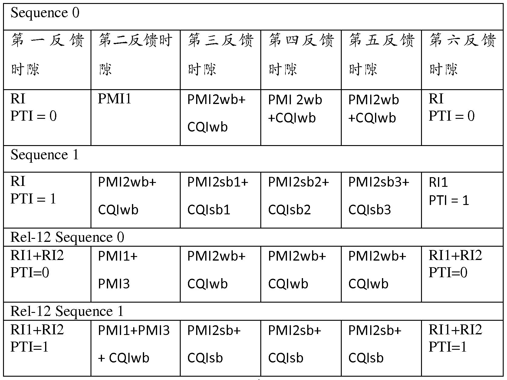


Claims


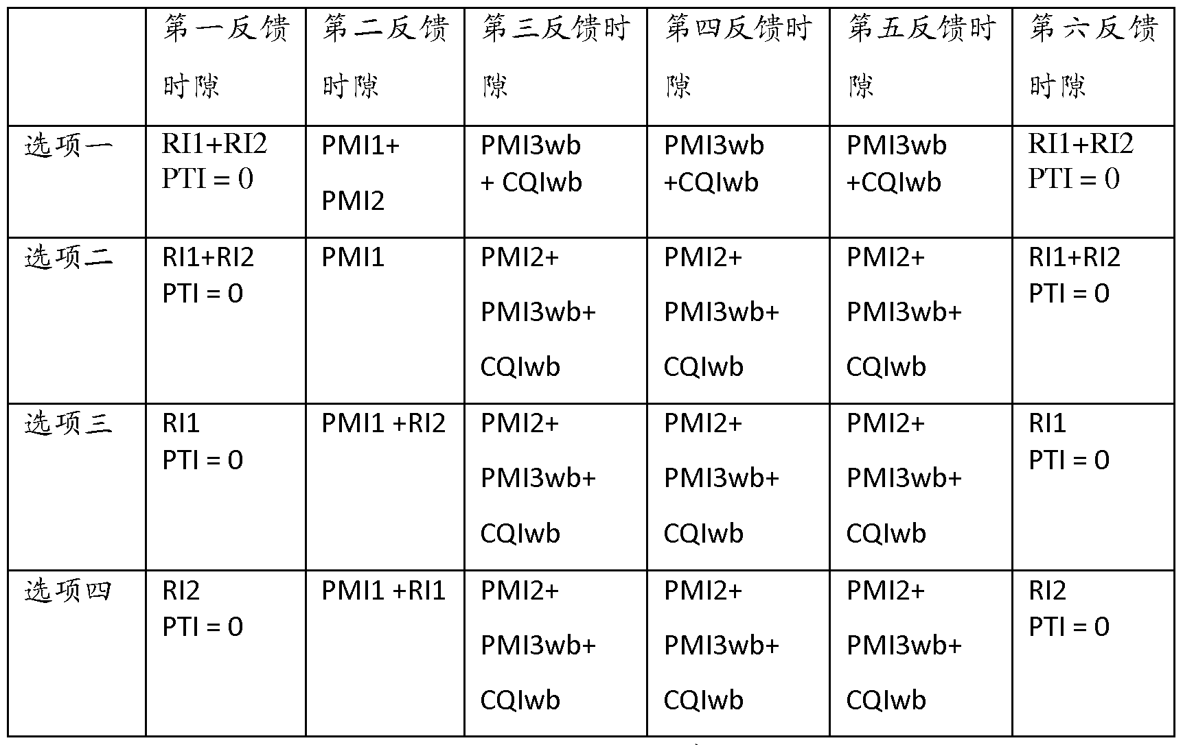
Priority Applications (6)
| Application Number | Priority Date | Filing Date | Title |
|---|---|---|---|
| CN201380003739.1A CN105009494B (zh) | 2013-11-22 | 2013-11-22 | 一种信道状态信息的反馈方法及装置 |
| EP13897692.3A EP3073662B1 (en) | 2013-11-22 | 2013-11-22 | Feedback method and apparatus of channel state information |
| PCT/CN2013/087728 WO2015074262A1 (zh) | 2013-11-22 | 2013-11-22 | 一种信道状态信息的反馈方法及装置 |
| KR1020167016715A KR101852914B1 (ko) | 2013-11-22 | 2013-11-22 | 채널 상태 정보의 피드백 방법 및 장치 |
| US15/160,919 US9838106B2 (en) | 2013-11-22 | 2016-05-20 | Method for feeding back channel state information and an apparatus |
| US15/829,206 US10567061B2 (en) | 2013-11-22 | 2017-12-01 | Method for feeding back channel state information and an apparatus |
Applications Claiming Priority (1)
| Application Number | Priority Date | Filing Date | Title |
|---|---|---|---|
| PCT/CN2013/087728 WO2015074262A1 (zh) | 2013-11-22 | 2013-11-22 | 一种信道状态信息的反馈方法及装置 |
Related Child Applications (1)
| Application Number | Title | Priority Date | Filing Date |
|---|---|---|---|
| US15/160,919 Continuation US9838106B2 (en) | 2013-11-22 | 2016-05-20 | Method for feeding back channel state information and an apparatus |
Publications (1)
| Publication Number | Publication Date |
|---|---|
| WO2015074262A1 true WO2015074262A1 (zh) | 2015-05-28 |
Family
ID=53178831
Family Applications (1)
| Application Number | Title | Priority Date | Filing Date |
|---|---|---|---|
| PCT/CN2013/087728 WO2015074262A1 (zh) | 2013-11-22 | 2013-11-22 | 一种信道状态信息的反馈方法及装置 |
Country Status (5)
| Country | Link |
|---|---|
| US (2) | US9838106B2 (zh) |
| EP (1) | EP3073662B1 (zh) |
| KR (1) | KR101852914B1 (zh) |
| CN (1) | CN105009494B (zh) |
| WO (1) | WO2015074262A1 (zh) |
Cited By (4)
| Publication number | Priority date | Publication date | Assignee | Title |
|---|---|---|---|---|
| WO2017167161A1 (zh) * | 2016-03-31 | 2017-10-05 | 中兴通讯股份有限公司 | 一种实现信道状态信息反馈的方法、装置及计算机存储介质 |
| CN110351824A (zh) * | 2018-04-04 | 2019-10-18 | 电信科学技术研究院有限公司 | 一种进行竞争随机接入的方法及设备 |
| WO2020151741A1 (en) * | 2019-01-23 | 2020-07-30 | Qualcomm Incorporated | Precoder matrix quantization for compressed csi feedback |
| WO2023173245A1 (en) * | 2022-03-14 | 2023-09-21 | Zte Corporation | Channel state information reporting |
Families Citing this family (19)
| Publication number | Priority date | Publication date | Assignee | Title |
|---|---|---|---|---|
| US10009075B2 (en) * | 2013-11-27 | 2018-06-26 | Lg Electronics Inc. | Operation for 3D beam forming in a wireless communication system |
| WO2016074119A1 (en) * | 2014-11-10 | 2016-05-19 | Qualcomm Incorporated | Elevation pmi reporting on pucch |
| CN105991483B (zh) | 2015-01-28 | 2020-08-07 | 索尼公司 | 无线通信设备和无线通信方法 |
| WO2016137061A1 (ko) * | 2015-02-26 | 2016-09-01 | 엘지전자 주식회사 | 무선 통신 시스템에서 csi 정보를 피드백하는 방법 및 그 장치 |
| EP3282629B1 (en) * | 2015-04-08 | 2020-09-09 | LG Electronics Inc. | Method for reporting channel state and apparatus therefor |
| CN106160928A (zh) * | 2015-04-09 | 2016-11-23 | 株式会社Ntt都科摩 | 生成预编码矩阵的方法、无线基站和装置以及移动台 |
| CN108352938B (zh) * | 2015-11-06 | 2021-03-23 | 华为技术有限公司 | 一种信道状态信息的测量与反馈方法、用户设备及基站 |
| US10159087B2 (en) * | 2015-12-11 | 2018-12-18 | Qualcomm Incorporated | Channel state information framework for advanced receivers |
| CN105871435B (zh) * | 2016-04-01 | 2019-04-02 | 北京北方烽火科技有限公司 | 信道状态信息反馈方法、装置及用户设备 |
| NZ747711A (en) * | 2016-05-13 | 2020-03-27 | Ericsson Telefon Ab L M | Multi-resolution csi feedback |
| KR102414697B1 (ko) | 2016-07-29 | 2022-06-29 | 삼성전자 주식회사 | 다수의 배열 안테나를 사용하는 이동통신 시스템에서 csi-rs 포트 공유를 위한 기준신호 설정 방법 및 장치 |
| WO2018029644A2 (en) * | 2016-08-12 | 2018-02-15 | Telefonaktiebolaget Lm Ericsson (Publ) | Progressive advanced csi feedback |
| US10484064B2 (en) * | 2016-09-01 | 2019-11-19 | Samsung Electronics Co., Ltd. | Method and apparatus for downlink and uplink CSI acquisition |
| CN108155968B (zh) * | 2016-12-05 | 2020-06-05 | 大唐移动通信设备有限公司 | 一种基站下行正交振幅调制256qam的配置方法和装置 |
| CN108288989B (zh) | 2017-01-09 | 2020-12-08 | 华为技术有限公司 | 信道状态信息反馈方法、用户设备及基站 |
| KR102364954B1 (ko) | 2017-05-04 | 2022-02-18 | 삼성전자 주식회사 | 무선 셀룰라 통신 시스템에서 상향 제어 채널의 자원 지시 방법 및 장치 |
| CN109150267B (zh) | 2017-06-16 | 2023-12-08 | 华为技术有限公司 | 一种信道状态信息发送、接收方法及设备 |
| CN108683487B (zh) | 2018-01-12 | 2019-06-11 | 华为技术有限公司 | 一种用于终端设备能力传输的方法、装置及系统 |
| CN116827396A (zh) * | 2022-03-22 | 2023-09-29 | 中兴通讯股份有限公司 | 信道状态信息的处理方法、终端、基站、介质 |
Citations (4)
| Publication number | Priority date | Publication date | Assignee | Title |
|---|---|---|---|---|
| CN102938688A (zh) * | 2011-08-15 | 2013-02-20 | 上海贝尔股份有限公司 | 用于多维天线阵列的信道测量和反馈的方法和设备 |
| CN103178888A (zh) * | 2011-12-23 | 2013-06-26 | 华为技术有限公司 | 一种反馈信道状态信息的方法及装置 |
| CN103209012A (zh) * | 2012-01-12 | 2013-07-17 | 上海贝尔股份有限公司 | 用于辅助多维天线阵列的信道测量的方法 |
| US20130258964A1 (en) * | 2012-03-30 | 2013-10-03 | Samsung Electronics Co., Ltd. | Apparatus and method for channel-state-information pilot design for an advanced wireless network |
Family Cites Families (23)
| Publication number | Priority date | Publication date | Assignee | Title |
|---|---|---|---|---|
| KR101478362B1 (ko) * | 2007-08-10 | 2015-01-28 | 엘지전자 주식회사 | 다중안테나 시스템에서 귀환데이터 전송방법 |
| US8781005B2 (en) * | 2009-10-01 | 2014-07-15 | Qualcomm Incorporated | Scalable quantization of channel state information for MIMO transmission |
| US9961579B2 (en) * | 2009-10-01 | 2018-05-01 | Qualcomm Incorporated | Scalable channel feedback for wireless communication |
| EP3737000B1 (en) * | 2010-04-01 | 2023-10-25 | LG Electronics Inc. | Method for transmitting channel state information in wireless access system |
| US8848817B2 (en) * | 2010-04-30 | 2014-09-30 | Texas Instruments Incorporated | Transmission modes and signaling for uplink MIMO support or single TB dual-layer transmission in LTE uplink |
| KR101790505B1 (ko) * | 2010-06-01 | 2017-11-21 | 주식회사 골드피크이노베이션즈 | 서브프레임 구성에 따른 채널상태정보-기준신호 할당 장치 및 방법 |
| CN102291218B (zh) | 2010-06-21 | 2016-06-15 | 夏普株式会社 | 信道状态信息反馈资源分配方法和信道状态信息反馈方法 |
| US8639198B2 (en) * | 2010-06-30 | 2014-01-28 | Samsung Electronics Co., Ltd. | Systems and methods for 8-TX codebook and feedback signaling in 3GPP wireless networks |
| CN103229578B (zh) * | 2010-09-15 | 2017-04-12 | 华为技术有限公司 | 用于无线通信系统中信道状态信息反馈的系统和方法 |
| KR101835326B1 (ko) * | 2010-09-26 | 2018-03-07 | 엘지전자 주식회사 | 다중 안테나 지원 무선 통신 시스템에서 효율적인 피드백 방법 및 장치 |
| WO2012044088A2 (ko) * | 2010-09-29 | 2012-04-05 | 엘지전자 주식회사 | 다중 안테나 지원 무선 통신 시스템에서 효율적인 피드백 방법 및 장치 |
| US9986444B2 (en) * | 2011-10-27 | 2018-05-29 | Lg Electronics Inc. | Method and apparatus for feeding back aggregated channel state information in cooperative multipoint communication system |
| KR101979400B1 (ko) * | 2012-01-27 | 2019-05-16 | 닛뽕덴끼 가부시끼가이샤 | 협력 다지점 송수신 |
| US9397738B2 (en) | 2012-05-17 | 2016-07-19 | Qualcomm Incorporated | Codebook and feedback design for high order MIMO |
| US8913682B2 (en) * | 2012-05-18 | 2014-12-16 | Samsung Electronics Co., Ltd. | Apparatus and method for channel state information codeword construction for a cellular wireless communication system |
| JP6072258B2 (ja) * | 2012-08-28 | 2017-02-01 | エルジー エレクトロニクス インコーポレイティド | 無線通信システムにおいてチャネル状態情報をフィードバックする方法及びそのための装置 |
| KR101972945B1 (ko) * | 2012-09-18 | 2019-04-29 | 삼성전자 주식회사 | 무선 통신 시스템에서 채널 상태 정보 송수신 방법 및 장치 |
| KR101988285B1 (ko) * | 2012-09-20 | 2019-06-12 | 삼성전자 주식회사 | 무선 통신 시스템에서 채널 상태 정보 송수신 방법 및 장치 |
| US9178583B2 (en) * | 2013-01-08 | 2015-11-03 | Samsung Electronics Co., Ltd. | Channel state information feedback design in advanced wireless communication systems |
| GB2509958B (en) * | 2013-01-18 | 2016-02-03 | Broadcom Corp | Methods, apparatus and computer programs for controlling feedbck about channel conditions |
| WO2014129858A1 (ko) * | 2013-02-24 | 2014-08-28 | 엘지전자 주식회사 | 무선 통신 시스템에서 3-차원 빔포밍을 위한 채널 상태 정보를 보고하는 방법 및 이를 위한 장치 |
| KR20150143421A (ko) * | 2013-04-10 | 2015-12-23 | 엘지전자 주식회사 | 무선 통신 시스템에서 다중 레이어 3차원 빔포밍을 위한 레이어 정합 방법 및 이를 위한 장치 |
| KR101832633B1 (ko) * | 2013-09-30 | 2018-02-26 | 후지쯔 가부시끼가이샤 | 정보 피드백 방법, 코드북 결정 방법, ue 및 기지국 |
-
2013
- 2013-11-22 KR KR1020167016715A patent/KR101852914B1/ko active IP Right Grant
- 2013-11-22 WO PCT/CN2013/087728 patent/WO2015074262A1/zh active Application Filing
- 2013-11-22 EP EP13897692.3A patent/EP3073662B1/en active Active
- 2013-11-22 CN CN201380003739.1A patent/CN105009494B/zh active Active
-
2016
- 2016-05-20 US US15/160,919 patent/US9838106B2/en active Active
-
2017
- 2017-12-01 US US15/829,206 patent/US10567061B2/en active Active
Patent Citations (4)
| Publication number | Priority date | Publication date | Assignee | Title |
|---|---|---|---|---|
| CN102938688A (zh) * | 2011-08-15 | 2013-02-20 | 上海贝尔股份有限公司 | 用于多维天线阵列的信道测量和反馈的方法和设备 |
| CN103178888A (zh) * | 2011-12-23 | 2013-06-26 | 华为技术有限公司 | 一种反馈信道状态信息的方法及装置 |
| CN103209012A (zh) * | 2012-01-12 | 2013-07-17 | 上海贝尔股份有限公司 | 用于辅助多维天线阵列的信道测量的方法 |
| US20130258964A1 (en) * | 2012-03-30 | 2013-10-03 | Samsung Electronics Co., Ltd. | Apparatus and method for channel-state-information pilot design for an advanced wireless network |
Non-Patent Citations (1)
| Title |
|---|
| See also references of EP3073662A4 * |
Cited By (5)
| Publication number | Priority date | Publication date | Assignee | Title |
|---|---|---|---|---|
| WO2017167161A1 (zh) * | 2016-03-31 | 2017-10-05 | 中兴通讯股份有限公司 | 一种实现信道状态信息反馈的方法、装置及计算机存储介质 |
| CN110351824A (zh) * | 2018-04-04 | 2019-10-18 | 电信科学技术研究院有限公司 | 一种进行竞争随机接入的方法及设备 |
| CN110351824B (zh) * | 2018-04-04 | 2021-10-12 | 大唐移动通信设备有限公司 | 一种进行竞争随机接入的方法及设备 |
| WO2020151741A1 (en) * | 2019-01-23 | 2020-07-30 | Qualcomm Incorporated | Precoder matrix quantization for compressed csi feedback |
| WO2023173245A1 (en) * | 2022-03-14 | 2023-09-21 | Zte Corporation | Channel state information reporting |
Also Published As
| Publication number | Publication date |
|---|---|
| EP3073662A4 (en) | 2016-12-07 |
| EP3073662A1 (en) | 2016-09-28 |
| CN105009494B (zh) | 2019-07-09 |
| US20160269089A1 (en) | 2016-09-15 |
| CN105009494A (zh) | 2015-10-28 |
| KR20160086948A (ko) | 2016-07-20 |
| US9838106B2 (en) | 2017-12-05 |
| US10567061B2 (en) | 2020-02-18 |
| EP3073662B1 (en) | 2020-10-07 |
| US20180091209A1 (en) | 2018-03-29 |
| KR101852914B1 (ko) | 2018-04-27 |
Similar Documents
| Publication | Publication Date | Title |
|---|---|---|
| US10567061B2 (en) | Method for feeding back channel state information and an apparatus | |
| EP3637838B1 (en) | Communication method and communication apparatus | |
| US9577724B2 (en) | Precoding matrix indicator feedback method, receive end, and transmit end | |
| EP3337053B1 (en) | Communication technique using csi-rs in mobile communication system | |
| CN107005293B (zh) | 用于部分预编码的信道状态信息参考信号和信道状态信息反馈的下行链路信令的方法和装置 | |
| KR101867392B1 (ko) | 채널 상태 정보의 피드백 방법 및 단말 | |
| US9258048B2 (en) | Method and terminal for feeding back channel state information | |
| EP3497809A2 (en) | Progressive advanced csi feedback | |
| JP2019520732A (ja) | マルチ解像度csiフィードバック | |
| CN110545134A (zh) | 信道状态信息汇报的方法及装置 | |
| WO2012059000A1 (zh) | 一种信道质量信息的上报方法及其装置 | |
| WO2012041107A1 (zh) | 信道状态信息反馈方法及终端 | |
| WO2011122919A2 (en) | User equipment apparatus and method for feeding back channel state information in a wireless communication system | |
| TWI789363B (zh) | 傳輸信道狀態資訊的方法和裝置 | |
| TWI771365B (zh) | 無線通信方法、終端設備和網絡設備 | |
| WO2012068880A1 (zh) | 一种信道状态信息反馈方法及装置 | |
| WO2011085679A1 (zh) | 一种额外的预编码矩阵索引的指示方法和系统 | |
| WO2012062197A1 (zh) | 一种信道质量信息的上报方法及其装置 | |
| WO2020221118A1 (zh) | 指示和确定预编码矩阵的方法以及通信装置 | |
| WO2015054879A1 (zh) | 信道状态信息的测量和反馈方法、终端及基站 | |
| US10659130B2 (en) | Terminal, base station, and channel information obtaining method | |
| WO2015135157A1 (zh) | 信道质量指示反馈方法、资源调度信息发送方法和装置 | |
| US11290906B2 (en) | Channel measurement method | |
| WO2020221117A1 (zh) | 一种用于构建预编码矩阵的系数指示方法和通信装置 | |
| WO2018039860A1 (zh) | 信道质量的测量和反馈方法和装置 |
Legal Events
| Date | Code | Title | Description |
|---|---|---|---|
| 121 | Ep: the epo has been informed by wipo that ep was designated in this application |
Ref document number: 13897692 Country of ref document: EP Kind code of ref document: A1 |
|
| NENP | Non-entry into the national phase |
Ref country code: DE |
|
| ENP | Entry into the national phase |
Ref document number: 20167016715 Country of ref document: KR Kind code of ref document: A |
|
| REEP | Request for entry into the european phase |
Ref document number: 2013897692 Country of ref document: EP |
|
| WWE | Wipo information: entry into national phase |
Ref document number: 2013897692 Country of ref document: EP |