WO2015072073A1 - Pulling-up-type continuous casting apparatus and pulling-up-type continuous casting method - Google Patents
Pulling-up-type continuous casting apparatus and pulling-up-type continuous casting method Download PDFInfo
- Publication number
- WO2015072073A1 WO2015072073A1 PCT/JP2014/005154 JP2014005154W WO2015072073A1 WO 2015072073 A1 WO2015072073 A1 WO 2015072073A1 JP 2014005154 W JP2014005154 W JP 2014005154W WO 2015072073 A1 WO2015072073 A1 WO 2015072073A1
- Authority
- WO
- WIPO (PCT)
- Prior art keywords
- molten metal
- metal
- molten
- defining member
- shape defining
- Prior art date
- Legal status (The legal status is an assumption and is not a legal conclusion. Google has not performed a legal analysis and makes no representation as to the accuracy of the status listed.)
- Ceased
Links
Images




Classifications
-
- B—PERFORMING OPERATIONS; TRANSPORTING
- B22—CASTING; POWDER METALLURGY
- B22D—CASTING OF METALS; CASTING OF OTHER SUBSTANCES BY THE SAME PROCESSES OR DEVICES
- B22D11/00—Continuous casting of metals, i.e. casting in indefinite lengths
- B22D11/14—Plants for continuous casting
- B22D11/145—Plants for continuous casting for upward casting
-
- B—PERFORMING OPERATIONS; TRANSPORTING
- B22—CASTING; POWDER METALLURGY
- B22D—CASTING OF METALS; CASTING OF OTHER SUBSTANCES BY THE SAME PROCESSES OR DEVICES
- B22D11/00—Continuous casting of metals, i.e. casting in indefinite lengths
- B22D11/08—Accessories for starting the casting procedure
-
- B—PERFORMING OPERATIONS; TRANSPORTING
- B22—CASTING; POWDER METALLURGY
- B22D—CASTING OF METALS; CASTING OF OTHER SUBSTANCES BY THE SAME PROCESSES OR DEVICES
- B22D11/00—Continuous casting of metals, i.e. casting in indefinite lengths
- B22D11/10—Supplying or treating molten metal
- B22D11/11—Treating the molten metal
- B22D11/114—Treating the molten metal by using agitating or vibrating means
- B22D11/115—Treating the molten metal by using agitating or vibrating means by using magnetic fields
-
- B—PERFORMING OPERATIONS; TRANSPORTING
- B22—CASTING; POWDER METALLURGY
- B22D—CASTING OF METALS; CASTING OF OTHER SUBSTANCES BY THE SAME PROCESSES OR DEVICES
- B22D18/00—Pressure casting; Vacuum casting
- B22D18/04—Low pressure casting, i.e. making use of pressures up to a few bars to fill the mould
-
- C—CHEMISTRY; METALLURGY
- C22—METALLURGY; FERROUS OR NON-FERROUS ALLOYS; TREATMENT OF ALLOYS OR NON-FERROUS METALS
- C22C—ALLOYS
- C22C1/00—Making non-ferrous alloys
- C22C1/12—Making non-ferrous alloys by processing in a semi-solid state, e.g. holding the alloy in the solid-liquid phase
Definitions
- the present invention relates to a pulling-up-type continuous casting apparatus and a pulling-up-type continuous casting method.
- Patent Literature 1 a free casting method as a revolutionary continuous casting method that does not requires any mold.
- molten metal i.e., molten-metal surface
- the starter is pulled up, so that some of the molten metal follows the starter and is drawn up by the starter by the surface film of the molten metal and/or the surface tension.
- the shape in the longitudinal direction as well as the shape in cross section is defined by the mold.
- the cast-metal article since the solidified metal (i.e., cast-metal article) needs to pass through the inside of the mold, the cast-metal article has such a shape that it extends in a straight-line shape in the longitudinal direction.
- the shape defining member used in the free casting method defines only the cross-sectional shape of the cast-metal article, while it does not define the shape in the longitudinal direction.
- the shape defining member can be moved in the direction parallel to the molten-metal surface (i.e., in the horizontal direction), cast-metal articles having various shapes in the longitudinal direction can be produced.
- Patent Literature 1 discloses a hollow cast-metal article (i.e., a pipe) having a zigzag shape or a helical shape in the longitudinal direction rather than the straight-line shape.
- Patent Literature 1 In the free casting method disclosed in Patent Literature 1, there is a problem that the solidification shrinkage of the molten metal that has passed through the shape defining member is so large that it is impossible to cast a high-precision cast-metal article.
- the present invention has been made in view of the above-described problem, and an object thereof is to provide a pulling-up-type continuous casting apparatus and a pulling-up-type continuous casting method capable of casting a high-precision cast-metal article by bringing molten metal into a slurry state and thereby reducing a solidification shrinkage of the molten metal.
- a pulling-up-type continuous casting apparatus includes: a slurry formation apparatus that brings molten metal into a slurry state; a holding vessel that holds the molten metal in the slurry state; and a shape defining member disposed in a vicinity of a molten-metal surface of the molten metal in the slurry state, the shape defining member being configured to define a cross-sectional shape of a cast-metal article to be cast as the molten metal in the slurry state passes through the shape defining member.
- the slurry formation apparatus preferably includes a cooling unit that lowers a temperature of the molten metal held in the holding vessel and a vibration unit that makes the molten metal vibrate.
- the pulling-up-type continuous casting apparatus preferably further includes a pressurization device that applies a pressure to the molten metal held in the holding vessel and thereby makes the molten metal in the slurry state pass through the shape defining member.
- the pressurization device preferably applies a pressure to the molten metal held in the holding vessel by moving the shape defining member into the molten metal held in the holding vessel.
- the pulling-up-type continuous casting apparatus preferably further includes a drawing section that makes the molten metal in the slurry state pass through the shape defining member and thereby draws the molten metal from the molten-metal surface.
- the pulling-up-type continuous casting apparatus preferably further includes a holding furnace that holds the molten metal, and the holding vessel is preferably a ladle that scoops up the molten metal held in the holding furnace and holds the scooped molten metal.
- a pulling-up-type continuous casting method includes: bringing molten metal held in a holding vessel into a slurry state; disposing a shape defining member in a vicinity of a molten-metal surface of the molten metal in the slurry state, the shape defining member being configured to define a cross-sectional shape of a cast-metal article to be cast; and drawing the molten metal in the slurry state from the molten-metal surface and making the drawn molten metal pass through the shape defining member.
- the solidification shrinkage of the molten metal is reduced, thus making it possible to cast a high-precision cast-metal article.
- the bringing the molten metal held in the holding vessel into the slurry state preferably includes lowering a temperature of the molten metal held in the holding vessel and making the molten metal vibrate.
- the pulling-up-type continuous casting method preferably further includes applying a pressure to the molten metal held in the holding vessel and thereby making the molten metal in the slurry state pass through the shape defining member.
- the pulling-up-type continuous casting method preferably further includes a drawing section that makes the molten metal in the slurry state pass through the shape defining member and thereby draws the molten metal from the molten-metal surface.
- the pulling-up-type continuous casting method preferably further includes a holding furnace that holds the molten metal, and the holding vessel is preferably a ladle that scoops up the molten metal held in the holding furnace and holds the scooped molten metal.
- a pulling-up-type continuous casting apparatus and a pulling-up-type continuous casting method capable of casting a high-precision cast-metal article by bringing molten metal into a slurry state and thereby reducing a solidification shrinkage of the molten metal.
- Fig. 1 is a cross section showing a configuration example of a free casting apparatus according to a first exemplary embodiment
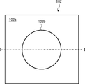
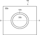
- Fig. 2 is a plane view of a shape defining member 102 provided in the free casting apparatus shown in Fig. 1
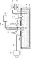
- Fig. 3 is a cross section showing a first specific configuration example of a free casting apparatus according to a first exemplary embodiment
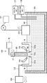
- Fig. 4 is a cross section showing a second specific configuration example of a free casting apparatus according to a second exemplary embodiment
- Fig. 5 is a cross section showing a configuration example of a free casting apparatus according to the second exemplary embodiment
- Fig. 6 is a cross section showing a configuration example of a free casting apparatus according to a third exemplary embodiment
- Fig. 1 is a cross section showing a configuration example of a free casting apparatus according to a first exemplary embodiment
- Fig. 2 is a plane view of a shape defining member 102 provided in the free casting apparatus shown in Fig. 1
- Fig. 3 is a
- FIG. 7 is a cross section showing a configuration example of a free casting apparatus according to a fourth exemplary embodiment
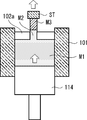
- Fig. 8 is a cross section showing a specific configuration example of a free casting apparatus according to the fourth exemplary embodiment
- Fig. 9 is a cross section showing another configuration example of the free casting apparatus shown in Fig. 1
- Fig. 10 is a plane view of a shape defining member 102 provided in the free casting apparatus shown in Fig. 9
- Fig. 11 is a cross section showing another configuration example of the free casting apparatus shown in Fig. 5.
- Fig. 1 is a cross section showing a configuration example of a free casting apparatus according to the first exemplary embodiment.
- the free casting apparatus according to the first exemplary embodiment includes a molten-metal holding vessel (holding vessel) 101, an outer-shape defining member 102a, a support rod 103, an actuator 104, a cooling nozzle 105, a drawing section 106, a cooling unit 107, and a vibration unit 108.
- the cooling unit 107 and the vibration unit 108 constitute a slurry formation apparatus.
- the molten-metal holding vessel 101 contains molten metal such as aluminum or its alloy, and maintains the molten metal at a predetermined temperature.
- molten metal such as aluminum or its alloy
- the surface of molten metal i.e., molten-metal surface
- the molten-metal holding vessel 101 may be replenished with molten metal as required during the casting process so that the molten-metal surface is kept at a fixed level.
- the molten metal may be a metal other than aluminum or an alloy thereof.
- the cooling unit 107 is used to cool molten metal held in the molten metal holding vessel 101.
- the cooling unit 107 cools molten metal held in the molten metal holding vessel 101 to a temperature equal to or close to the freezing point of the molten metal.
- the vibration unit 108 is used to make the molten metal cooled by the cooling unit 107 vibrate.
- the vibration unit 108 stirs the molten metal cooled by the cooling unit 107 and thereby makes the molten metal vibrate.
- the vibration unit 108 gives ultrasonic vibrations or electromagnetic vibrations to the molten metal cooled by the cooling unit 107.
- the molten metal may be mixed with composite particles made of alumina, silica, or the like, and then the molten metal may be made to vibrate.
- the molten metal becomes a slurry state in which the liquid and the solid particles are mixed. Since the molten metal in a slurry state is a Bingham fluid, it tends to maintain a given shape and its solidification shrinkage is small. For example, the molten metal in a slurry state is less likely to affected by the surface tension and the like, and less likely to become roundish.
- the molten metal M0 the molten metal before being brought into a slurry state
- molten metal M1 the molten metal after being brought into a slurry state
- the outer-shape defining member 102a is made of ceramic or stainless, for example, and disposed in the vicinity of the molten-metal surface.
- the outer-shape defining member 102a is disposed so that the outer-shape defining member 102a is in contact with the molten-metal surface.
- the outer-shape defining member 102a may be disposed so that its bottom main surface (molten-metal surface side) is not in contact with the molten-metal surface.
- the outer-shape defining member 102a may be disposed so that a predetermined gap (e.g., about 0.5mm) is formed between the bottom main surface and the molten-metal surface.
- the outer-shape defining member 102a defines the outer shape of a cast metal M3 to be cast.
- the cast metal M3 shown in Fig. 1 is a cylindrical solid cast-metal article having a circular shape in a horizontal cross section (hereinafter referred to as "lateral cross section"). That is, more specifically, the outer-shape defining member 102a defines the outer diameter on the lateral cross section of the cast metal M3.
- Fig. 2 is a plane view of the outer-shape defining member 102a.
- the cross section of the outer-shape defining member 102a shown in Fig. 1 corresponds to a cross section taken along the line I-I in Fig. 2.
- the outer-shape defining member 102a has, for example, a rectangular shape as viewed from the top, and has a circular opening at the center. This opening serves as a molten-metal passage section 102b through which molten metal passes.
- the outer-shape defining member 102a and the molten-metal passage section 102b constitute a shape defining member 102.
- the drawing section 106 includes a starter (drawing member) ST that is submerged into the molten metal M1, and a pulling-up machine PL that drives the starter ST, for example, in the vertical direction.
- the molten metal M1 follows the starter ST and is pulled up by the starter ST while maintaining its outer shape by its surface film and/or the surface tension. Then, the molten metal M1 passes through the molten-metal passage section 102b. Note that the molten metal that follows the starter ST (or the cast metal M3 that is formed as the molten metal M1 drawn by the starter ST solidifies) and is pulled up from the molten-metal surface by the surface film of the molten metal M1 and/or the surface tension is called "held molten metal M2". Further, the interface between the cast metal M3 and the held molten metal M2 is the solidification interface.
- the starter ST is formed of, for example, material having a high melting point no lower than the melting point of the molten metal M1.
- the starter ST is formed of, for example, aluminum, stainless, iron, an alloy thereof, or the like.
- the starter ST may be formed of ceramic. As a result, the erosion of the starter is prevented to some extent.
- the surface of the starter ST may be covered with a protection film (not shown) such as a salt crystal film.
- a protection film such as a salt crystal film.
- the melt bonding between the starter ST and the molten metal M1 is suppressed, thereby improving the removal property between the starter ST and the cast metal M3.
- the starter ST can be reused.
- the starter ST may have unevenness on its surface. This facilitates the adhesion (precipitation) of a protection film on the surface of the starter ST, thus improving the removal property between the starter ST and the cast metal M3 even further.
- the bonding force between the starter ST and the molten metal M1 in the pulling-up direction at the time when the molten metal is drawn can also be improved.
- the support rod 103 supports the outer-shape defining member 102a. Note that the support rod 103 is connected to the actuator 104.
- the actuator 104 has a function of moving the outer-shape defining member 102a in the up/down direction (vertical direction) and in the horizontal direction through the support rod 103. In this manner, it is possible to move the outer-shape defining member 102a downward as the molten-metal surface is lowered due to the advance of the casting process. Further, since the outer-shape defining member 102a can be moved in the horizontal direction, the shape in the longitudinal direction of the cast metal M3 can be arbitrarily changed.
- the cooling nozzle (cooling unit) 105 sprays a cooling gas (such as air, nitrogen, and argon) on the starter ST and/or the cast metal M3, and thereby cools the starter ST and/or the cast metal M3.
- a cooling gas such as air, nitrogen, and argon
- molten metal M0 is put in the molten metal holding vessel 101.
- the molten metal M0 in the molten metal holding vessel 101 is brought into a slurry state and hence changed to molten metal M1 by cooling and vibrating the molten metal M0.
- the outer-shape defining member 102a is disposed in the vicinity of the molten-metal surface of the molten metal M1 in the slurry state.
- the starter ST is lowered, made to pass through the molten-metal passage section 102b, and submerged into the molten metal M1.
- the starter ST starts to be pulled up at a predetermined speed.
- the molten metal M1 follows the starter ST and is pulled up (drawn) from the molten-metal surface by the surface film and/or the surface tension.
- the pulled-up molten metal M1 forms held molten metal M2.
- the held molten metal M2 is formed in the molten-metal passage section 102b. In other words, the held molten metal M2 is shaped into a given shape by the outer-shape defining member 102a.
- the starter ST and the cast metal M3 are cooled by a cooling gas sprayed from the cooling nozzle 105.
- the held molten metal M2 is successively solidified from its upper side toward its lower side, and hence the cast metal M3 grows. In this manner, the cast metal M3 can be continuously cast.
- the held molten metal M2 in the slurry state is a Bingham fluid. Therefore, the held molten metal M2 tends to maintain the shape given by the outer-shape defining member 102a and its solidification shrinkage is small. As a result, it is possible to cast a high-precision cast metal M3.
- the free casting apparatus brings molten metal into a slurry state.
- the free casting apparatus can reduce the solidification shrinkage of the held molten metal M2 and maintain the shape given to the held molten metal M2 by the shape defining member 102. Consequently, the free casting apparatus according to this exemplary embodiment can cast a high-precision cast metal M3.
- the free casting apparatus according to this exemplary embodiment can speed up the solidification of the held molten metal M2 by bringing the molten metal into a slurry state, the productivity of the cast metal M3 can be improved. Further, the free casting apparatus according to this exemplary embodiment improves the material strength of the cast metal M3 by bringing the molten metal into a slurry state.
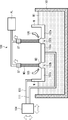
- Fig. 3 is a cross section showing a first specific configuration example of the free casting apparatus according shown in Fig. 1.
- the free casting apparatus shown in Fig. 3 further includes a molten metal holding furnace (holding furnace) 100 that holds molten metal M0 before being brought into a slurry state and uses a ladle as the molten metal holding vessel 101.
- the ladle scoops up molten metal M0 held in the molten metal holding furnace 100 and holds the scooped molten metal.
- the cooling unit 107 and the vibration unit 108 bring the molten metal M0 contained in the ladle into a slurry state and hence change the molten metal M0 to molten metal M1 by cooling and vibrating the molten metal M0 in the ladle.
- the other configuration of the free casting apparatus shown in Fig. 3 is similar to that of the free casting apparatus shown in Fig. 1, and therefore its explanation is omitted.
- the molten metal M0 may be brought into a slurry state outside the ladle.
- Fig. 4 is a cross section showing a second specific configuration example of the free casting apparatus according shown in Fig. 1.
- the molten metal holding furnace 100 is used as the molten metal holding vessel 101.
- an enclosure section 109 is disposed so as to surround part of the molten metal M0 located in the vicinity of the held molten metal M2.
- a tubular enclosure section 109 whose axis is in the vertical direction, is disposed in the vicinity of the held molten metal M2.
- the cooling unit 107 and the vibration unit 108 bring the molten metal M0 surrounded by the enclosure section 109 into a slurry state and hence change the molten metal M0 to molten metal M1 by cooling and vibrating the molten metal M0 surrounded by the enclosure section 109.
- the other configuration of the free casting apparatus shown in Fig. 4 is similar to that of the free casting apparatus shown in Fig. 1, and therefore its explanation is omitted.
- a heater may be further provided in the vicinity of the bottom end of the tubular enclosure section 109. As a result, it is possible to prevent the temperature of the molten metal M0 located outside the enclosure section 109 from decreasing due to the influence of the molten metal M1 surrounded by the enclosure section 109.
- Fig. 5 is a cross section showing a configuration example of a free casting apparatus according to a second exemplary embodiment.
- the free casting apparatus shown in Fig. 5 further includes a pressurization device that applies a pressure to the molten metal M1.
- the molten metal M1 is pushed up from the molten-metal surface through the molten-metal passage section 102b as the held molten metal M2. Therefore, it is possible to improve the drawn-up property of the molten metal M1.
- the second exemplary embodiment is explained hereinafter in detail.
- the actuator 104 has a function as a pressurization device that applies a pressure to the molten metal M1. Specifically, the actuator 104 moves the outer-shape defining member 102a into the molten metal M1 (downward) and thereby applies a pressure to the molten metal M1.
- the molten metal M1 is pushed up from the molten-metal surface through the molten-metal passage section 102b as the held molten metal M2 (the molten metal M1 passes through the molten-metal passage section 102b as the held molten metal M2).
- the free casting apparatus shown in Fig. 5 can reduce the resistance that the molten metal M1 (or the held molten metal M2) receives from the outer-shape defining member 102a when the molten metal is drawn up. Therefore, the free casting apparatus can draw up the molten metal M1 without causing the molten metal M1 to be torn off even when the molten metal M1 is in a slurry state with a high viscosity. That is, the free casting apparatus shown in Fig. 5 can improve the drawn-up property of the molten metal M1.
- a sidewall W that extends vertically upward from the outer edge of the outer-shape defining member 102a is formed in order to prevent the molten metal M1 from flowing over the outer edge of the outer-shape defining member 102a into the upper main surface thereof when the outer-shape defining member 102a moves into the molten metal M1.
- Fig. 6 is a cross section showing a configuration example of a free casting apparatus according to a third exemplary embodiment.
- the free casting apparatus shown in Fig. 6 includes a pressurization device having a configuration different from that of the pressurization device of the free casting apparatus shown in Fig. 5.
- the free casting apparatus shown in Fig. 6 further includes a lid 110 for hermetically enclosing the molten metal M1 and a fluid supply unit (pressurization unit) 111 that feeds a fluid into the hermetically enclosed area.
- a tubular stalk S that extends from the inner edge of the outer-shape defining member 102a (that is, from the molten-metal passage section 102b) to the molten-metal surface of the molten metal M1. Note that in the example shown in Fig.
- the sidewall W that extends vertically upward from the outer edge of the outer-shape defining member 102a does not have to be provided because no molten metal M1 flows over the outer edge of the outer-shape defining member 102a into the upper main surface thereof.
- the other configuration of the free casting apparatus shown in Fig. 6 is similar to that of the free casting apparatus shown in Fig. 5, and therefore its explanation is omitted.
- the lid 110 closes the opened section of the molten metal holding vessel 101. That is, the molten metal holding vessel 101 and the lid 110 constitute an enclosed vessel that hermetically encloses the molten metal M1. However, the lid 110 includes an opened section having such a size that the stalk S can pass through the opened section.
- the stalk S extends from the inner edge of the outer-shape defining member 102a (that is, from the molten-metal passage section 102b) to the molten-metal surface of the molten metal M1 through the opened section.
- the fluid supply unit 111 applies a pressure to the molten metal M1 by feeding a fluid such as atmospheric air into the enclosed vessel.
- a fluid such as atmospheric air
- the molten metal M1 passes through the stalk S and the molten-metal passage section 102b. Therefore, the free casting apparatus shown in Fig. 6 can produce advantageous effects equivalent to those of the free casting apparatus shown in Fig. 5.
- Fig. 7 is a cross section showing a configuration example of a free casting apparatus according to a fourth exemplary embodiment.
- the free casting apparatus shown in Fig. 7 includes a pressurization device having a configuration different from that of the pressurization device of the free casting apparatus shown in Fig. 5.
- the free casting apparatus shown in Fig. 7 further includes an object 112 and a drive unit 113 that drives the object 112 in the up/down direction (vertical direction).
- the other configuration of the free casting apparatus shown in Fig. 7 is similar to that of the free casting apparatus shown in Fig. 5, and therefore its explanation is omitted.
- the object 112 is formed of material having a melting point higher than that of the molten metal M1.
- the drive unit 113 moves the object 112 from outside of the molten metal M1 into the molten metal M1 and thereby applies a pressure to the molten metal M1.
- the free casting apparatus shown in Fig. 7 can produce advantageous effects equivalent to those of the free casting apparatus shown in Fig. 5.
- Fig. 8 is a cross section showing a specific configuration example of the free casting apparatus according shown in Fig. 7.
- the free casting apparatus shown in Fig. 8 casts a cast metal M3 by using the output mechanism of the so-called "squeeze casting".
- a pressure is applied to the molten metal M1 contained in a cylinder, which serves as the molten metal holding vessel 101, by moving a pushing mechanism 114, which serves as the object 112, into the cylinder.
- the free casting apparatuses according to the first to fourth exemplary embodiments bring molten metal into a slurry state.
- the free casting apparatuses can reduce the solidification shrinkage of the held molten metal M2 and maintain the shape given to the held molten metal M2 by the shape defining member. Consequently, the free casting apparatuses according to these exemplary embodiments can cast a high-precision cast metal M3.
- Fig. 9 is a cross section showing another specific configuration example of the free casting apparatus according shown in Fig. 1.
- the free casting apparatus shown in Fig. 9 includes an inner-shape defining member 102c in addition to the outer-shape defining member 102a.
- the inner-shape defining member 102c defines the inner shape of a cast metal M3 to be cast and the outer-shape defining member 102a defines the outer shape of the cast metal M3 to be cast.
- the cast metal M3 shown in Fig. 9 is a hollow cast-metal article having a ring shape in a horizontal cross section (hereinafter referred to as "lateral cross section") (that is, the cast metal M3 shown in Fig. 9 is a pipe). That is, more specifically, the inner-shape defining member 102c defines the inner diameter on the lateral cross section of the cast metal M3 and the outer-shape defining member 102a defines the outer diameter on the lateral cross section of the cast metal M3.
- Fig. 10 is a plane view of the inner-shape defining member 102c and the outer-shape defining member 102a. Note that the cross section of the inner-shape defining member 102c and the outer-shape defining member 102a in Fig. 9 corresponds to a cross section taken along the line II-II in Fig. 10. As shown in Fig. 10, the outer-shape defining member 102a has, for example, a rectangular shape as viewed from the top, and has a circular opening at the center. The inner-shape defining member 102c has a circular shape as viewed from the top and is disposed at the center of the opening of the outer-shape defining member 102a.
- the gap between the inner-shape defining member 102c and the outer-shape defining member 102a serves as the molten-metal passage section 102b through which the molten metal passes.
- the inner-shape defining member 102c, the outer-shape defining member 102a, and the molten-metal passage section 102b constitute a shape defining member 102.
- Fig. 11 is a cross section showing another specific configuration example of the free casting apparatus according shown in Fig. 5.
- the free casting apparatus shown in Fig. 11 includes an inner-shape defining member 102c in addition to the outer-shape defining member 102a. Details of the shape defining member 102 including the inner-shape defining member 102c and the outer-shape defining member 102a are the same as those explained above, and therefore their explanation is omitted.
- MOLTEN METAL HOLDING FURNACE 101 MOLTEN METAL HOLDING VESSEL 102 SHAPE DEFINING MEMBER 102a OUTER-SHAPE DEFINING MEMBER 102b MOLTEN-METAL PASSAGE SECTION 102c INNER-SHAPE DEFINING MEMBER 103 SUPPORT ROD 104 ACTUATOR 105 COOLING NOZZLE 106 DRAWING SECTION 107 COOLING UNIT 108 VIBRATION UNIT 109 ENCLOSURE SECTION 110 LID 111 FLUID SUPPLY UNIT 112 OBJECT 113 DRIVE UNIT 114 PUSHING MECHANISM M0 MOLTEN METAL M1 MOLTEN METAL M2 HELD MOLTEN METAL M3 CAST METAL S STALK ST STARTER W SIDEWALL
Landscapes
- Engineering & Computer Science (AREA)
- Mechanical Engineering (AREA)
- Chemical & Material Sciences (AREA)
- Materials Engineering (AREA)
- Metallurgy (AREA)
- Organic Chemistry (AREA)
- Continuous Casting (AREA)
Abstract
A pulling-up-type continuous casting apparatus according to an aspect of the present invention includes a slurry formation apparatus that brings molten metal (M0) into a slurry state, a molten-metal holding vessel (101) that holds the molten metal (M1) in the slurry state, and a shape defining member (102) disposed in a vicinity of a molten-metal surface of the molten metal (M1) in the slurry state, the shape defining member (102) being configured to define a cross-sectional shape of a cast-metal article to be cast as the molten metal (M1) in the slurry state passes through the shape defining member (102).
Description
The present invention relates to a pulling-up-type continuous casting apparatus and a pulling-up-type continuous casting method.
The inventors of the present application have proposed, in Patent Literature 1, a free casting method as a revolutionary continuous casting method that does not requires any mold. As shown in Patent Literature 1, after a starter is submerged under the surface of a melted metal (molten metal) (i.e., molten-metal surface), the starter is pulled up, so that some of the molten metal follows the starter and is drawn up by the starter by the surface film of the molten metal and/or the surface tension. Note that it is possible to continuously cast a cast-metal article having a desired cross-sectional shape by drawing the molten metal and cooling the drawn molten metal through a shape defining member disposed in the vicinity of the molten-metal surface.
In the ordinary continuous casting method, the shape in the longitudinal direction as well as the shape in cross section is defined by the mold. In the continuous casting method, in particular, since the solidified metal (i.e., cast-metal article) needs to pass through the inside of the mold, the cast-metal article has such a shape that it extends in a straight-line shape in the longitudinal direction. In contrast to this, the shape defining member used in the free casting method defines only the cross-sectional shape of the cast-metal article, while it does not define the shape in the longitudinal direction. Further, since the shape defining member can be moved in the direction parallel to the molten-metal surface (i.e., in the horizontal direction), cast-metal articles having various shapes in the longitudinal direction can be produced. For example, Patent Literature 1 discloses a hollow cast-metal article (i.e., a pipe) having a zigzag shape or a helical shape in the longitudinal direction rather than the straight-line shape.
PL1: Japanese Unexamined Patent Application Publication No. 2012-61518
The present inventors have found the following problem. In the free casting method disclosed in Patent Literature 1, there is a problem that the solidification shrinkage of the molten metal that has passed through the shape defining member is so large that it is impossible to cast a high-precision cast-metal article.
The present invention has been made in view of the above-described problem, and an object thereof is to provide a pulling-up-type continuous casting apparatus and a pulling-up-type continuous casting method capable of casting a high-precision cast-metal article by bringing molten metal into a slurry state and thereby reducing a solidification shrinkage of the molten metal.
A pulling-up-type continuous casting apparatus according to an aspect of the present invention includes: a slurry formation apparatus that brings molten metal into a slurry state; a holding vessel that holds the molten metal in the slurry state; and a shape defining member disposed in a vicinity of a molten-metal surface of the molten metal in the slurry state, the shape defining member being configured to define a cross-sectional shape of a cast-metal article to be cast as the molten metal in the slurry state passes through the shape defining member. As a result, the solidification shrinkage of the molten metal is reduced, thus making it possible to cast a high-precision cast-metal article.
The slurry formation apparatus preferably includes a cooling unit that lowers a temperature of the molten metal held in the holding vessel and a vibration unit that makes the molten metal vibrate.
The pulling-up-type continuous casting apparatus preferably further includes a pressurization device that applies a pressure to the molten metal held in the holding vessel and thereby makes the molten metal in the slurry state pass through the shape defining member.
The pressurization device preferably applies a pressure to the molten metal held in the holding vessel by moving the shape defining member into the molten metal held in the holding vessel.
The pulling-up-type continuous casting apparatus preferably further includes a drawing section that makes the molten metal in the slurry state pass through the shape defining member and thereby draws the molten metal from the molten-metal surface.
The pulling-up-type continuous casting apparatus preferably further includes a holding furnace that holds the molten metal, and the holding vessel is preferably a ladle that scoops up the molten metal held in the holding furnace and holds the scooped molten metal.
A pulling-up-type continuous casting method according to an aspect of the present invention includes: bringing molten metal held in a holding vessel into a slurry state; disposing a shape defining member in a vicinity of a molten-metal surface of the molten metal in the slurry state, the shape defining member being configured to define a cross-sectional shape of a cast-metal article to be cast; and drawing the molten metal in the slurry state from the molten-metal surface and making the drawn molten metal pass through the shape defining member. As a result, the solidification shrinkage of the molten metal is reduced, thus making it possible to cast a high-precision cast-metal article.
The bringing the molten metal held in the holding vessel into the slurry state preferably includes lowering a temperature of the molten metal held in the holding vessel and making the molten metal vibrate.
The pulling-up-type continuous casting method preferably further includes applying a pressure to the molten metal held in the holding vessel and thereby making the molten metal in the slurry state pass through the shape defining member.
It is preferable to apply a pressure to the molten metal held in the holding vessel by moving the shape defining member into the molten metal held in the holding vessel.
The pulling-up-type continuous casting method preferably further includes a drawing section that makes the molten metal in the slurry state pass through the shape defining member and thereby draws the molten metal from the molten-metal surface.
The pulling-up-type continuous casting method preferably further includes a holding furnace that holds the molten metal, and the holding vessel is preferably a ladle that scoops up the molten metal held in the holding furnace and holds the scooped molten metal.
According to the present invention, it is possible to provide a pulling-up-type continuous casting apparatus and a pulling-up-type continuous casting method capable of casting a high-precision cast-metal article by bringing molten metal into a slurry state and thereby reducing a solidification shrinkage of the molten metal.
Specific exemplary embodiments to which the present invention is applied are explained hereinafter in detail with reference to the drawings. However, the present invention is not limited to exemplary embodiments shown below. Further, the following descriptions and the drawings are simplified as appropriate for clarifying the explanation.
<First exemplary embodiment>
Firstly, a free casting apparatus (pulling-up-type continuous casting apparatus) according to a first exemplary embodiment is explained with reference to Fig. 1. Fig. 1 is a cross section showing a configuration example of a free casting apparatus according to the first exemplary embodiment. As shown in Fig. 1, the free casting apparatus according to the first exemplary embodiment includes a molten-metal holding vessel (holding vessel) 101, an outer-shape defining member 102a, a support rod 103, an actuator 104, a cooling nozzle 105, a drawing section 106, a cooling unit 107, and a vibration unit 108. Note that the cooling unit 107 and the vibration unit 108 constitute a slurry formation apparatus.
Firstly, a free casting apparatus (pulling-up-type continuous casting apparatus) according to a first exemplary embodiment is explained with reference to Fig. 1. Fig. 1 is a cross section showing a configuration example of a free casting apparatus according to the first exemplary embodiment. As shown in Fig. 1, the free casting apparatus according to the first exemplary embodiment includes a molten-metal holding vessel (holding vessel) 101, an outer-
The molten-metal holding vessel 101 contains molten metal such as aluminum or its alloy, and maintains the molten metal at a predetermined temperature. In the example shown in Fig. 1, since the molten-metal holding vessel 101 is not replenished with molten metal during the casting process, the surface of molten metal (i.e., molten-metal surface) is lowered as the casting process advances. Alternatively, the molten-metal holding vessel 101 may be replenished with molten metal as required during the casting process so that the molten-metal surface is kept at a fixed level. Needless to say, the molten metal may be a metal other than aluminum or an alloy thereof.
The cooling unit 107 is used to cool molten metal held in the molten metal holding vessel 101. For example, the cooling unit 107 cools molten metal held in the molten metal holding vessel 101 to a temperature equal to or close to the freezing point of the molten metal. The vibration unit 108 is used to make the molten metal cooled by the cooling unit 107 vibrate. For example, the vibration unit 108 stirs the molten metal cooled by the cooling unit 107 and thereby makes the molten metal vibrate. Alternatively, the vibration unit 108 gives ultrasonic vibrations or electromagnetic vibrations to the molten metal cooled by the cooling unit 107. Note that the molten metal may be mixed with composite particles made of alumina, silica, or the like, and then the molten metal may be made to vibrate.
As a result, the molten metal becomes a slurry state in which the liquid and the solid particles are mixed. Since the molten metal in a slurry state is a Bingham fluid, it tends to maintain a given shape and its solidification shrinkage is small. For example, the molten metal in a slurry state is less likely to affected by the surface tension and the like, and less likely to become roundish. In the following explanation, the molten metal before being brought into a slurry state is referred to as "molten metal M0" and the molten metal after being brought into a slurry state is referred to as "molten metal M1".
The outer-shape defining member 102a is made of ceramic or stainless, for example, and disposed in the vicinity of the molten-metal surface. In the example shown in Fig. 1, the outer-shape defining member 102a is disposed so that the outer-shape defining member 102a is in contact with the molten-metal surface. However, the outer-shape defining member 102a may be disposed so that its bottom main surface (molten-metal surface side) is not in contact with the molten-metal surface. Specifically, the outer-shape defining member 102a may be disposed so that a predetermined gap (e.g., about 0.5mm) is formed between the bottom main surface and the molten-metal surface.
The outer-shape defining member 102a defines the outer shape of a cast metal M3 to be cast. The cast metal M3 shown in Fig. 1 is a cylindrical solid cast-metal article having a circular shape in a horizontal cross section (hereinafter referred to as "lateral cross section"). That is, more specifically, the outer-shape defining member 102a defines the outer diameter on the lateral cross section of the cast metal M3.
Fig. 2 is a plane view of the outer-shape defining member 102a. Note that the cross section of the outer-shape defining member 102a shown in Fig. 1 corresponds to a cross section taken along the line I-I in Fig. 2. As shown in Fig. 2, the outer-shape defining member 102a has, for example, a rectangular shape as viewed from the top, and has a circular opening at the center. This opening serves as a molten-metal passage section 102b through which molten metal passes. In this manner, the outer-shape defining member 102a and the molten-metal passage section 102b constitute a shape defining member 102.
The drawing section 106 includes a starter (drawing member) ST that is submerged into the molten metal M1, and a pulling-up machine PL that drives the starter ST, for example, in the vertical direction.
As shown in Fig. 1, after the molten metal M1 adheres to the submerged starter ST, the molten metal M1 follows the starter ST and is pulled up by the starter ST while maintaining its outer shape by its surface film and/or the surface tension. Then, the molten metal M1 passes through the molten-metal passage section 102b. Note that the molten metal that follows the starter ST (or the cast metal M3 that is formed as the molten metal M1 drawn by the starter ST solidifies) and is pulled up from the molten-metal surface by the surface film of the molten metal M1 and/or the surface tension is called "held molten metal M2". Further, the interface between the cast metal M3 and the held molten metal M2 is the solidification interface.
The starter ST is formed of, for example, material having a high melting point no lower than the melting point of the molten metal M1. Specifically, the starter ST is formed of, for example, aluminum, stainless, iron, an alloy thereof, or the like. Alternatively, the starter ST may be formed of ceramic. As a result, the erosion of the starter is prevented to some extent.
Note that the surface of the starter ST may be covered with a protection film (not shown) such as a salt crystal film. In this way, the melt bonding between the starter ST and the molten metal M1 is suppressed, thereby improving the removal property between the starter ST and the cast metal M3. As a result, the starter ST can be reused. Further, the starter ST may have unevenness on its surface. This facilitates the adhesion (precipitation) of a protection film on the surface of the starter ST, thus improving the removal property between the starter ST and the cast metal M3 even further. At the same time, the bonding force between the starter ST and the molten metal M1 in the pulling-up direction at the time when the molten metal is drawn can also be improved.
The support rod 103 supports the outer-shape defining member 102a. Note that the support rod 103 is connected to the actuator 104.
The actuator 104 has a function of moving the outer-shape defining member 102a in the up/down direction (vertical direction) and in the horizontal direction through the support rod 103. In this manner, it is possible to move the outer-shape defining member 102a downward as the molten-metal surface is lowered due to the advance of the casting process. Further, since the outer-shape defining member 102a can be moved in the horizontal direction, the shape in the longitudinal direction of the cast metal M3 can be arbitrarily changed.
The cooling nozzle (cooling unit) 105 sprays a cooling gas (such as air, nitrogen, and argon) on the starter ST and/or the cast metal M3, and thereby cools the starter ST and/or the cast metal M3. By cooling the starter ST and/or the cast metal M3 by the cooling gas while pulling up the cast metal M3 by using the pulling-up machine PL connected to the starter ST, the held molten metal M2 located in the vicinity of the solidification interface is successively solidified and the cast metal M3 is continuously formed.
Next, a free casting method according to this exemplary embodiment is explained with reference to Fig. 1.
Firstly, molten metal M0 is put in the molten metal holding vessel 101.
Next, the molten metal M0 in the molten metal holding vessel 101 is brought into a slurry state and hence changed to molten metal M1 by cooling and vibrating the molten metal M0.
Next, the outer-shape defining member 102a is disposed in the vicinity of the molten-metal surface of the molten metal M1 in the slurry state.
Next, the starter ST is lowered, made to pass through the molten-metal passage section 102b, and submerged into the molten metal M1.
Next, the starter ST starts to be pulled up at a predetermined speed. Note that even when the starter ST is pulled away from the molten-metal surface, the molten metal M1 follows the starter ST and is pulled up (drawn) from the molten-metal surface by the surface film and/or the surface tension. The pulled-up molten metal M1 forms held molten metal M2. As shown in Fig. 1, the held molten metal M2 is formed in the molten-metal passage section 102b. In other words, the held molten metal M2 is shaped into a given shape by the outer-shape defining member 102a.
Next, the starter ST and the cast metal M3 are cooled by a cooling gas sprayed from the cooling nozzle 105. As a result, the held molten metal M2 is successively solidified from its upper side toward its lower side, and hence the cast metal M3 grows. In this manner, the cast metal M3 can be continuously cast.
Note that the held molten metal M2 in the slurry state is a Bingham fluid. Therefore, the held molten metal M2 tends to maintain the shape given by the outer-shape defining member 102a and its solidification shrinkage is small. As a result, it is possible to cast a high-precision cast metal M3.
As described above, the free casting apparatus according to this exemplary embodiment brings molten metal into a slurry state. As a result, the free casting apparatus can reduce the solidification shrinkage of the held molten metal M2 and maintain the shape given to the held molten metal M2 by the shape defining member 102. Consequently, the free casting apparatus according to this exemplary embodiment can cast a high-precision cast metal M3.
Further, since the free casting apparatus according to this exemplary embodiment can speed up the solidification of the held molten metal M2 by bringing the molten metal into a slurry state, the productivity of the cast metal M3 can be improved. Further, the free casting apparatus according to this exemplary embodiment improves the material strength of the cast metal M3 by bringing the molten metal into a slurry state.
Next, specific configuration examples of a free casting apparatus according to this exemplary embodiment are explained with reference to Figs. 3 and 4.
(First specific configuration example of free casting apparatus according to first exemplary embodiment)
Fig. 3 is a cross section showing a first specific configuration example of the free casting apparatus according shown in Fig. 1. In comparison to the free casting apparatus shown in Fig. 1, the free casting apparatus shown in Fig. 3 further includes a molten metal holding furnace (holding furnace) 100 that holds molten metal M0 before being brought into a slurry state and uses a ladle as the moltenmetal holding vessel 101. The ladle scoops up molten metal M0 held in the molten metal holding furnace 100 and holds the scooped molten metal. The cooling unit 107 and the vibration unit 108 bring the molten metal M0 contained in the ladle into a slurry state and hence change the molten metal M0 to molten metal M1 by cooling and vibrating the molten metal M0 in the ladle. The other configuration of the free casting apparatus shown in Fig. 3 is similar to that of the free casting apparatus shown in Fig. 1, and therefore its explanation is omitted.
Fig. 3 is a cross section showing a first specific configuration example of the free casting apparatus according shown in Fig. 1. In comparison to the free casting apparatus shown in Fig. 1, the free casting apparatus shown in Fig. 3 further includes a molten metal holding furnace (holding furnace) 100 that holds molten metal M0 before being brought into a slurry state and uses a ladle as the molten
Although an example case where the molten metal M0 is brought into a slurry state in a ladle is explained in this example, the molten metal M0 may be brought into a slurry state outside the ladle.
(Second specific configuration example of free casting apparatus according to first exemplary embodiment)
Fig. 4 is a cross section showing a second specific configuration example of the free casting apparatus according shown in Fig. 1. In the free casting apparatus shown in Fig. 4, the moltenmetal holding furnace 100 is used as the molten metal holding vessel 101. In this molten metal holding furnace 100, an enclosure section 109 is disposed so as to surround part of the molten metal M0 located in the vicinity of the held molten metal M2. In the example shown in Fig. 4, a tubular enclosure section 109, whose axis is in the vertical direction, is disposed in the vicinity of the held molten metal M2. The cooling unit 107 and the vibration unit 108 bring the molten metal M0 surrounded by the enclosure section 109 into a slurry state and hence change the molten metal M0 to molten metal M1 by cooling and vibrating the molten metal M0 surrounded by the enclosure section 109. The other configuration of the free casting apparatus shown in Fig. 4 is similar to that of the free casting apparatus shown in Fig. 1, and therefore its explanation is omitted.
Fig. 4 is a cross section showing a second specific configuration example of the free casting apparatus according shown in Fig. 1. In the free casting apparatus shown in Fig. 4, the molten
Note that a heater may be further provided in the vicinity of the bottom end of the tubular enclosure section 109. As a result, it is possible to prevent the temperature of the molten metal M0 located outside the enclosure section 109 from decreasing due to the influence of the molten metal M1 surrounded by the enclosure section 109.
<Second exemplary embodiment>
Fig. 5 is a cross section showing a configuration example of a free casting apparatus according to a second exemplary embodiment. In comparison to the free casting apparatus shown in Fig. 1, the free casting apparatus shown in Fig. 5 further includes a pressurization device that applies a pressure to the molten metal M1. As a result, the molten metal M1 is pushed up from the molten-metal surface through the molten-metal passage section 102b as the held molten metal M2. Therefore, it is possible to improve the drawn-up property of the molten metal M1. The second exemplary embodiment is explained hereinafter in detail.
Fig. 5 is a cross section showing a configuration example of a free casting apparatus according to a second exemplary embodiment. In comparison to the free casting apparatus shown in Fig. 1, the free casting apparatus shown in Fig. 5 further includes a pressurization device that applies a pressure to the molten metal M1. As a result, the molten metal M1 is pushed up from the molten-metal surface through the molten-
In the example shown in Fig. 5, the actuator 104 has a function as a pressurization device that applies a pressure to the molten metal M1. Specifically, the actuator 104 moves the outer-shape defining member 102a into the molten metal M1 (downward) and thereby applies a pressure to the molten metal M1. Then, when the outer-shape defining member 102a moves to a position lower than the molten-metal surface of the molten metal M1, the molten metal M1 is pushed up from the molten-metal surface through the molten-metal passage section 102b as the held molten metal M2 (the molten metal M1 passes through the molten-metal passage section 102b as the held molten metal M2).
As a result, the free casting apparatus shown in Fig. 5 can reduce the resistance that the molten metal M1 (or the held molten metal M2) receives from the outer-shape defining member 102a when the molten metal is drawn up. Therefore, the free casting apparatus can draw up the molten metal M1 without causing the molten metal M1 to be torn off even when the molten metal M1 is in a slurry state with a high viscosity. That is, the free casting apparatus shown in Fig. 5 can improve the drawn-up property of the molten metal M1.
Note that in the example shown in Fig. 5, a sidewall W that extends vertically upward from the outer edge of the outer-shape defining member 102a is formed in order to prevent the molten metal M1 from flowing over the outer edge of the outer-shape defining member 102a into the upper main surface thereof when the outer-shape defining member 102a moves into the molten metal M1.
<Third exemplary embodiment>
Fig. 6 is a cross section showing a configuration example of a free casting apparatus according to a third exemplary embodiment. The free casting apparatus shown in Fig. 6 includes a pressurization device having a configuration different from that of the pressurization device of the free casting apparatus shown in Fig. 5.
Fig. 6 is a cross section showing a configuration example of a free casting apparatus according to a third exemplary embodiment. The free casting apparatus shown in Fig. 6 includes a pressurization device having a configuration different from that of the pressurization device of the free casting apparatus shown in Fig. 5.
Specifically, in comparison to the free casting apparatus shown in Fig. 5, the free casting apparatus shown in Fig. 6 further includes a lid 110 for hermetically enclosing the molten metal M1 and a fluid supply unit (pressurization unit) 111 that feeds a fluid into the hermetically enclosed area. Further, in the example shown in Fig. 6, a tubular stalk S that extends from the inner edge of the outer-shape defining member 102a (that is, from the molten-metal passage section 102b) to the molten-metal surface of the molten metal M1. Note that in the example shown in Fig. 6, the sidewall W that extends vertically upward from the outer edge of the outer-shape defining member 102a does not have to be provided because no molten metal M1 flows over the outer edge of the outer-shape defining member 102a into the upper main surface thereof. The other configuration of the free casting apparatus shown in Fig. 6 is similar to that of the free casting apparatus shown in Fig. 5, and therefore its explanation is omitted.
The lid 110 closes the opened section of the molten metal holding vessel 101. That is, the molten metal holding vessel 101 and the lid 110 constitute an enclosed vessel that hermetically encloses the molten metal M1. However, the lid 110 includes an opened section having such a size that the stalk S can pass through the opened section. The stalk S extends from the inner edge of the outer-shape defining member 102a (that is, from the molten-metal passage section 102b) to the molten-metal surface of the molten metal M1 through the opened section.
The fluid supply unit 111 applies a pressure to the molten metal M1 by feeding a fluid such as atmospheric air into the enclosed vessel. As a result, the molten metal M1 passes through the stalk S and the molten-metal passage section 102b. Therefore, the free casting apparatus shown in Fig. 6 can produce advantageous effects equivalent to those of the free casting apparatus shown in Fig. 5.
<Fourth exemplary embodiment>
Fig. 7 is a cross section showing a configuration example of a free casting apparatus according to a fourth exemplary embodiment. The free casting apparatus shown in Fig. 7 includes a pressurization device having a configuration different from that of the pressurization device of the free casting apparatus shown in Fig. 5.
Fig. 7 is a cross section showing a configuration example of a free casting apparatus according to a fourth exemplary embodiment. The free casting apparatus shown in Fig. 7 includes a pressurization device having a configuration different from that of the pressurization device of the free casting apparatus shown in Fig. 5.
Specifically, in comparison to the free casting apparatus shown in Fig. 5, the free casting apparatus shown in Fig. 7 further includes an object 112 and a drive unit 113 that drives the object 112 in the up/down direction (vertical direction). The other configuration of the free casting apparatus shown in Fig. 7 is similar to that of the free casting apparatus shown in Fig. 5, and therefore its explanation is omitted.
The object 112 is formed of material having a melting point higher than that of the molten metal M1. The drive unit 113 moves the object 112 from outside of the molten metal M1 into the molten metal M1 and thereby applies a pressure to the molten metal M1. As a result, the free casting apparatus shown in Fig. 7 can produce advantageous effects equivalent to those of the free casting apparatus shown in Fig. 5.
Fig. 8 is a cross section showing a specific configuration example of the free casting apparatus according shown in Fig. 7. The free casting apparatus shown in Fig. 8 casts a cast metal M3 by using the output mechanism of the so-called "squeeze casting". In the example shown in Fig. 8, a pressure is applied to the molten metal M1 contained in a cylinder, which serves as the molten metal holding vessel 101, by moving a pushing mechanism 114, which serves as the object 112, into the cylinder.
As described above, the free casting apparatuses according to the first to fourth exemplary embodiments bring molten metal into a slurry state. As a result, the free casting apparatuses can reduce the solidification shrinkage of the held molten metal M2 and maintain the shape given to the held molten metal M2 by the shape defining member. Consequently, the free casting apparatuses according to these exemplary embodiments can cast a high-precision cast metal M3.
Although example cases where a cast-metal article having a cylindrical shape (cylindrical cast-metal article) is cast are explained in the above-described first to fourth exemplary embodiments, the present invention is not limited to such examples. The present invention can also be applied to cases where a cast-metal article having a tubular shape, a square pillar shape, a square tubular shape, or other shapes is cast. A case where a cast-metal article having a tubular shape is cast is briefly explained hereinafter with reference to Figs. 9, 10 and 11.
Fig. 9 is a cross section showing another specific configuration example of the free casting apparatus according shown in Fig. 1. The free casting apparatus shown in Fig. 9 includes an inner-shape defining member 102c in addition to the outer-shape defining member 102a.
The inner-shape defining member 102c defines the inner shape of a cast metal M3 to be cast and the outer-shape defining member 102a defines the outer shape of the cast metal M3 to be cast. The cast metal M3 shown in Fig. 9 is a hollow cast-metal article having a ring shape in a horizontal cross section (hereinafter referred to as "lateral cross section") (that is, the cast metal M3 shown in Fig. 9 is a pipe). That is, more specifically, the inner-shape defining member 102c defines the inner diameter on the lateral cross section of the cast metal M3 and the outer-shape defining member 102a defines the outer diameter on the lateral cross section of the cast metal M3.
Fig. 10 is a plane view of the inner-shape defining member 102c and the outer-shape defining member 102a. Note that the cross section of the inner-shape defining member 102c and the outer-shape defining member 102a in Fig. 9 corresponds to a cross section taken along the line II-II in Fig. 10. As shown in Fig. 10, the outer-shape defining member 102a has, for example, a rectangular shape as viewed from the top, and has a circular opening at the center. The inner-shape defining member 102c has a circular shape as viewed from the top and is disposed at the center of the opening of the outer-shape defining member 102a. The gap between the inner-shape defining member 102c and the outer-shape defining member 102a serves as the molten-metal passage section 102b through which the molten metal passes. In this manner, the inner-shape defining member 102c, the outer-shape defining member 102a, and the molten-metal passage section 102b constitute a shape defining member 102. With this configuration, a cast-metal article having a tubular shape is cast.
Fig. 11 is a cross section showing another specific configuration example of the free casting apparatus according shown in Fig. 5. The free casting apparatus shown in Fig. 11 includes an inner-shape defining member 102c in addition to the outer-shape defining member 102a. Details of the shape defining member 102 including the inner-shape defining member 102c and the outer-shape defining member 102a are the same as those explained above, and therefore their explanation is omitted.
Note that the present invention is not limited to the above-described first to fourth exemplary embodiments, and various modifications can be made without departing the spirit and scope of the present invention. For example, the above-described configuration examples may be combined and used at the same time.
This application is based upon and claims the benefit of priority from Japanese patent application No. 2013-236638, filed on November 15, 2013, the disclosure of which is incorporated herein in its entirety by reference.
100 MOLTEN METAL HOLDING FURNACE
101 MOLTEN METAL HOLDING VESSEL
102 SHAPE DEFINING MEMBER
102a OUTER-SHAPE DEFINING MEMBER
102b MOLTEN-METAL PASSAGE SECTION
102c INNER-SHAPE DEFINING MEMBER
103 SUPPORT ROD
104 ACTUATOR
105 COOLING NOZZLE
106 DRAWING SECTION
107 COOLING UNIT
108 VIBRATION UNIT
109 ENCLOSURE SECTION
110 LID
111 FLUID SUPPLY UNIT
112 OBJECT
113 DRIVE UNIT
114 PUSHING MECHANISM
M0 MOLTEN METAL
M1 MOLTEN METAL
M2 HELD MOLTEN METAL
M3 CAST METAL
S STALK
ST STARTER
W SIDEWALL
101 MOLTEN METAL HOLDING VESSEL
102 SHAPE DEFINING MEMBER
102a OUTER-SHAPE DEFINING MEMBER
102b MOLTEN-METAL PASSAGE SECTION
102c INNER-SHAPE DEFINING MEMBER
103 SUPPORT ROD
104 ACTUATOR
105 COOLING NOZZLE
106 DRAWING SECTION
107 COOLING UNIT
108 VIBRATION UNIT
109 ENCLOSURE SECTION
110 LID
111 FLUID SUPPLY UNIT
112 OBJECT
113 DRIVE UNIT
114 PUSHING MECHANISM
M0 MOLTEN METAL
M1 MOLTEN METAL
M2 HELD MOLTEN METAL
M3 CAST METAL
S STALK
ST STARTER
W SIDEWALL
Claims (12)
- A pulling-up-type continuous casting apparatus comprising:
a slurry formation apparatus that brings molten metal into a slurry state;
a holding vessel that holds the molten metal in the slurry state; and
a shape defining member disposed in a vicinity of a molten-metal surface of the molten metal in the slurry state, the shape defining member being configured to define a cross-sectional shape of a cast-metal article to be cast as the molten metal in the slurry state passes through the shape defining member.
- The pulling-up-type continuous casting apparatus according to Claim 1, wherein the slurry formation apparatus comprises:
a cooling unit that lowers a temperature of the molten metal held in the holding vessel; and
a vibration unit that makes the molten metal vibrate.
- The pulling-up-type continuous casting apparatus according to Claim 1 or 2, wherein further comprising a pressurization device that applies a pressure to the molten metal held in the holding vessel and thereby makes the molten metal in the slurry state pass through the shape defining member.
- The pulling-up-type continuous casting apparatus according to Claim 1, wherein the pressurization device applies a pressure to the molten metal held in the holding vessel by moving the shape defining member into the molten metal held in the holding vessel.
- The pulling-up-type continuous casting apparatus according to any one of Claims 1 to 4, further comprising a drawing section that makes the molten metal in the slurry state pass through the shape defining member and thereby draws the molten metal from the molten-metal surface.
- The pulling-up-type continuous casting apparatus according to any one of Claims 1 to 5, further comprising a holding furnace that holds the molten metal, wherein
the holding vessel is a ladle that scoops up the molten metal held in the holding furnace and holds the scooped molten metal.
- A pulling-up-type continuous casting method comprising:
bringing molten metal held in a holding vessel into a slurry state;
disposing a shape defining member in a vicinity of a molten-metal surface of the molten metal in the slurry state, the shape defining member being configured to define a cross-sectional shape of a cast-metal article to be cast; and
drawing the molten metal in the slurry state from the molten-metal surface and making the drawn molten metal pass through the shape defining member.
- The pulling-up-type continuous casting method according to Claim 7, wherein the bringing the molten metal held in the holding vessel into the slurry state comprises:
lowering a temperature of the molten metal held in the holding vessel; and
making the molten metal vibrate.
- The pulling-up-type continuous casting method according to Claim 7 or 8, wherein further comprising applying a pressure to the molten metal held in the holding vessel and thereby making the molten metal in the slurry state pass through the shape defining member.
- The pulling-up-type continuous casting method according to Claim 9, wherein a pressure is applied to the molten metal held in the holding vessel by moving the shape defining member into the molten metal held in the holding vessel.
- The pulling-up-type continuous casting method according to any one of Claims 7 to 10, further comprising a drawing section that makes the molten metal in the slurry state pass through the shape defining member and thereby draws the molten metal from the molten-metal surface.
- The pulling-up-type continuous casting method according to any one of Claims 7 to 11, further comprising a holding furnace that holds the molten metal, wherein
the holding vessel is a ladle that scoops up the molten metal held in the holding furnace and holds the scooped molten metal.
Applications Claiming Priority (2)
| Application Number | Priority Date | Filing Date | Title |
|---|---|---|---|
| JP2013-236638 | 2013-11-15 | ||
| JP2013236638A JP2015096269A (en) | 2013-11-15 | 2013-11-15 | Pull-up type continuous casting apparatus and pull-up type continuous casting method |
Publications (1)
| Publication Number | Publication Date |
|---|---|
| WO2015072073A1 true WO2015072073A1 (en) | 2015-05-21 |
Family
ID=51866290
Family Applications (1)
| Application Number | Title | Priority Date | Filing Date |
|---|---|---|---|
| PCT/JP2014/005154 Ceased WO2015072073A1 (en) | 2013-11-15 | 2014-10-09 | Pulling-up-type continuous casting apparatus and pulling-up-type continuous casting method |
Country Status (2)
| Country | Link |
|---|---|
| JP (1) | JP2015096269A (en) |
| WO (1) | WO2015072073A1 (en) |
Cited By (2)
| Publication number | Priority date | Publication date | Assignee | Title |
|---|---|---|---|---|
| EP3106246A1 (en) * | 2015-06-15 | 2016-12-21 | Toyota Jidosha Kabushiki Kaisha | Pulling-up-type continuous casting apparatus and pulling-up-type continuous casting method |
| CN111974961A (en) * | 2019-09-19 | 2020-11-24 | 北京科技大学 | A radially functionally graded composite material casting equipment and method |
Citations (3)
| Publication number | Priority date | Publication date | Assignee | Title |
|---|---|---|---|---|
| US4688625A (en) * | 1983-11-11 | 1987-08-25 | Mitsubishi Kinzoku Kabushiki Kaisha | Method of vertical continuous casting |
| WO2012035752A1 (en) * | 2010-09-17 | 2012-03-22 | Kabushiki Kaisha Toyota Chuo Kenkyusho | Free casting method, free casting apparatus, and casting |
| WO2013136785A1 (en) * | 2012-03-16 | 2013-09-19 | Toyota Jidosha Kabushiki Kaisha | Manufacturing method of casting, manufacturing device thereof, and casting |
-
2013
- 2013-11-15 JP JP2013236638A patent/JP2015096269A/en active Pending
-
2014
- 2014-10-09 WO PCT/JP2014/005154 patent/WO2015072073A1/en not_active Ceased
Patent Citations (4)
| Publication number | Priority date | Publication date | Assignee | Title |
|---|---|---|---|---|
| US4688625A (en) * | 1983-11-11 | 1987-08-25 | Mitsubishi Kinzoku Kabushiki Kaisha | Method of vertical continuous casting |
| WO2012035752A1 (en) * | 2010-09-17 | 2012-03-22 | Kabushiki Kaisha Toyota Chuo Kenkyusho | Free casting method, free casting apparatus, and casting |
| JP2012061518A (en) | 2010-09-17 | 2012-03-29 | Toyota Central R&D Labs Inc | Free casting method, free casting apparatus, and casting |
| WO2013136785A1 (en) * | 2012-03-16 | 2013-09-19 | Toyota Jidosha Kabushiki Kaisha | Manufacturing method of casting, manufacturing device thereof, and casting |
Cited By (3)
| Publication number | Priority date | Publication date | Assignee | Title |
|---|---|---|---|---|
| EP3106246A1 (en) * | 2015-06-15 | 2016-12-21 | Toyota Jidosha Kabushiki Kaisha | Pulling-up-type continuous casting apparatus and pulling-up-type continuous casting method |
| CN111974961A (en) * | 2019-09-19 | 2020-11-24 | 北京科技大学 | A radially functionally graded composite material casting equipment and method |
| CN111974961B (en) * | 2019-09-19 | 2022-04-29 | 北京科技大学 | A radially functionally graded composite material casting equipment and method |
Also Published As
| Publication number | Publication date |
|---|---|
| JP2015096269A (en) | 2015-05-21 |
Similar Documents
| Publication | Publication Date | Title |
|---|---|---|
| JP5373728B2 (en) | Free casting method, free casting apparatus and casting | |
| KR860000126B1 (en) | Method of electromagnetic thin strip casting | |
| WO2015072073A1 (en) | Pulling-up-type continuous casting apparatus and pulling-up-type continuous casting method | |
| JP5565734B2 (en) | Aluminum alloy continuous casting rod, continuous casting rod casting method, continuous casting equipment | |
| WO2015072074A1 (en) | Pulling-up-type continuous casting apparatus and pulling-up-type continuous casting method | |
| EP3028791A1 (en) | Hoisting-type continuous casting device and hoisting-type continuous casting method | |
| WO2015092508A1 (en) | Up-drawing continuous casting method, up-drawing continuous casting apparatus, and continuous casting | |
| ITMI20000096A1 (en) | PROCEDURE AND DEVICE TO IMPROVE THE QUALITY OF METALLIC BODIES CAST CONTINUOUSLY | |
| JP2016147298A (en) | Continuous casting apparatus | |
| JP2014076454A (en) | METHOD FOR MANUFACTURING Al-Si BASED CASTING ALLOY | |
| JP5450205B2 (en) | Pouring nozzle | |
| JP2007118041A (en) | Aluminum alloy-made continuously cast bar and method for casting continuously cast bar and continuous casting apparatus | |
| JP7068628B2 (en) | Casting method | |
| JP2021079397A (en) | Manufacturing method of titanium ingot, and mold for manufacturing titanium ingot | |
| ITMI20000361A1 (en) | METHOD AND DEVICE FOR CONTINUOUS CASTING OF MELTED MATERIALS | |
| EP2962784A1 (en) | Hoisting type continuous casting device and hoisting type continuous casting method | |
| JP2013226581A (en) | Method for producing casting and production device therefor | |
| CN105102154A (en) | Upward continuous casting apparatus and upward continuous casting method | |
| JP2004098082A (en) | Casting method of molten stainless steel with electromagnetic stirring | |
| JP2008142717A (en) | Ti, Ti alloy, or TiAl ingot-making method and ingot-making apparatus | |
| US20150034269A1 (en) | Pulling-up-type continuous casting apparatus and pulling-up-type continuous casting method | |
| JP2019188432A (en) | Casting method | |
| KR0185285B1 (en) | Method of manufacturing ingot having unidirectional freezing or single crystal organism | |
| JPH0243569B2 (en) | ||
| JPH02255246A (en) | Method and apparatus for electromagnetic field casting |
Legal Events
| Date | Code | Title | Description |
|---|---|---|---|
| 121 | Ep: the epo has been informed by wipo that ep was designated in this application |
Ref document number: 14793901 Country of ref document: EP Kind code of ref document: A1 |
|
| NENP | Non-entry into the national phase |
Ref country code: DE |
|
| 122 | Ep: pct application non-entry in european phase |
Ref document number: 14793901 Country of ref document: EP Kind code of ref document: A1 |