WO2015068461A1 - Optical connector plug - Google Patents
Optical connector plug Download PDFInfo
- Publication number
- WO2015068461A1 WO2015068461A1 PCT/JP2014/073731 JP2014073731W WO2015068461A1 WO 2015068461 A1 WO2015068461 A1 WO 2015068461A1 JP 2014073731 W JP2014073731 W JP 2014073731W WO 2015068461 A1 WO2015068461 A1 WO 2015068461A1
- Authority
- WO
- WIPO (PCT)
- Prior art keywords
- housing
- optical connector
- release
- connector plug
- front housing
- Prior art date
Links
Images


Classifications
-
- G—PHYSICS
- G02—OPTICS
- G02B—OPTICAL ELEMENTS, SYSTEMS OR APPARATUS
- G02B6/00—Light guides; Structural details of arrangements comprising light guides and other optical elements, e.g. couplings
- G02B6/24—Coupling light guides
- G02B6/36—Mechanical coupling means
- G02B6/38—Mechanical coupling means having fibre to fibre mating means
- G02B6/3807—Dismountable connectors, i.e. comprising plugs
- G02B6/389—Dismountable connectors, i.e. comprising plugs characterised by the method of fastening connecting plugs and sockets, e.g. screw- or nut-lock, snap-in, bayonet type
- G02B6/3893—Push-pull type, e.g. snap-in, push-on
-
- G—PHYSICS
- G02—OPTICS
- G02B—OPTICAL ELEMENTS, SYSTEMS OR APPARATUS
- G02B6/00—Light guides; Structural details of arrangements comprising light guides and other optical elements, e.g. couplings
- G02B6/24—Coupling light guides
- G02B6/36—Mechanical coupling means
- G02B6/38—Mechanical coupling means having fibre to fibre mating means
- G02B6/3807—Dismountable connectors, i.e. comprising plugs
- G02B6/3869—Mounting ferrules to connector body, i.e. plugs
- G02B6/387—Connector plugs comprising two complementary members, e.g. shells, caps, covers, locked together
-
- G—PHYSICS
- G02—OPTICS
- G02B—OPTICAL ELEMENTS, SYSTEMS OR APPARATUS
- G02B6/00—Light guides; Structural details of arrangements comprising light guides and other optical elements, e.g. couplings
- G02B6/24—Coupling light guides
- G02B6/36—Mechanical coupling means
- G02B6/38—Mechanical coupling means having fibre to fibre mating means
- G02B6/3807—Dismountable connectors, i.e. comprising plugs
- G02B6/381—Dismountable connectors, i.e. comprising plugs of the ferrule type, e.g. fibre ends embedded in ferrules, connecting a pair of fibres
- G02B6/3818—Dismountable connectors, i.e. comprising plugs of the ferrule type, e.g. fibre ends embedded in ferrules, connecting a pair of fibres of a low-reflection-loss type
- G02B6/3821—Dismountable connectors, i.e. comprising plugs of the ferrule type, e.g. fibre ends embedded in ferrules, connecting a pair of fibres of a low-reflection-loss type with axial spring biasing or loading means
Abstract
Description
さらに、前記フロントハウジングの後部に差し込まれたプラグフレームを有し、前記溝部は、該プラグフレームの後部に形成されていることが好ましい。 The rear housing is prevented from sliding rearward at a position adjacent to the rear side of the front housing at the rear end of the front housing in a state where the rear housing is attached to the rear end and advanced. It is preferable that a groove for mounting the blocking member is formed.
Furthermore, it is preferable to have a plug frame inserted into the rear portion of the front housing, and the groove portion is formed in the rear portion of the plug frame.
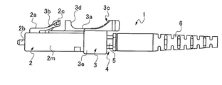
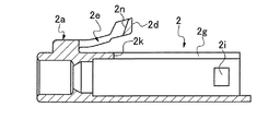
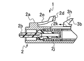
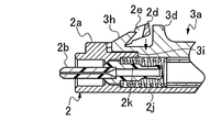
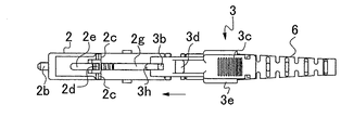
2 フロントハウジング、 2a ラッチ片、
2b フェルール、 2c ロック用係止部、
2d 解除部、 2e スリット、
2f 後方規制部、 2g ガイド用スリット、
2h リアハウジング用係合凹部、2i 係止窓部、
2j フェルール付勢部材、 2k 前方規制端面、
2m フロントハウジング本体、 2n 傾斜面、
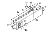
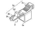
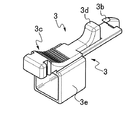
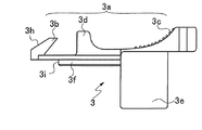
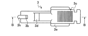
3 リアハウジング、 3a 解除レバー、
3b フック部、 3c 摘まみ部、
3d 突起部、 3e 筒本体、
3f ガイドレール、 3g 規制突起、
3h テーパ部、 3i 位置規制端部、
3j 位置規制端面、 3k テーパ面
3m 頂面
4 プラグフレーム、
5 溝部、
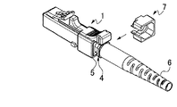
6 ブーツ、
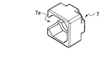
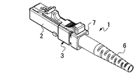
7 阻止部材、 7a スリット、
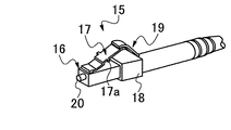
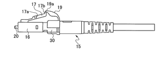
15 従来の光コネクタプラグ、
16 フロントハウジング、
17 ラッチ部、 17a 係合突起、
17b 先端部、
18 リアハウジング、
19 解除バー、 19a 先端部、
20 フェルール、 21 連結相手部材。 1 optical connector plug,
2 Front housing, 2a Latch piece,
2b ferrule, 2c locking part,
2d release part, 2e slit,
2f rear regulating part, 2g slit for guide,
2h engagement recess for rear housing, 2i locking window,
2j ferrule biasing member, 2k front regulating end face,
2m front housing body, 2n inclined surface,
3 Rear housing, 3a Release lever,
3b hook part, 3c knob part,
3d protrusion, 3e cylinder body,
3f guide rail, 3g regulating protrusion,
3h taper part, 3i position regulating end part,
3j Position regulating end face, 3k Tapered
5 groove,
6 boots,
7 blocking member, 7a slit,
15 Conventional optical connector plug,
16 front housing,
17 Latch part, 17a Engagement protrusion,
17b tip,
18 rear housing,
19 Release bar, 19a Tip,
20 Ferrule, 21 Connection partner member.
Claims (6)
- フェルールを保持して連結相手部材の嵌合部に嵌合するフロントハウジングと、
該フロントハウジングの後部側で前後方向にスライド自在に該フロントハウジングに装着されるリアハウジングとからなる光コネクタプラグであって、
前記フロントハウジングは、フロントハウジング本体と、その上側外壁面に形成された弾性を有するラッチ片とを有するとともに、該ラッチ片は、前記連結相手部材の嵌合用係合部に係合するように形成されたロック用係止部と、当該嵌合用係合部から前記ロック用係止部を係合状態から解除させるように形成された解除部とを有しており、
前記リアハウジングは、筒本体と、その上側に形成された解除レバーを有するとともに、該解除レバーは、該解除レバーの前部に形成されるとともに前記ラッチ部の解除部に該リアハウジングの後退時に係合して解除作用させるためのフック部と、該解除レバーの後部に形成された後退用の摘まみ部を有してなり、
前記解除レバーに形成されたフック部は、該フロントハウジングとリアハウジングの組み立て時に、前記フック部が前記ラッチ片の解除部の下に摺接しながら入り込むとともに、
当該フック部の先端側のテーパ部で前記解除部を押し上げて当該解除部の前側に形成したスリットに進入し遊嵌されることによって組み立てられること、
を特徴とする光コネクタプラグ。 A front housing that holds the ferrule and fits into the fitting portion of the connection partner member;
An optical connector plug comprising a rear housing that is slidable in the front-rear direction on the rear side of the front housing;
The front housing includes a front housing main body and an elastic latch piece formed on an upper outer wall surface of the front housing, and the latch piece is formed to engage with a fitting engagement portion of the connection partner member. A locking engagement portion, and a release portion formed so as to release the locking engagement portion from the engagement state from the engagement portion for fitting,
The rear housing has a cylinder body and a release lever formed on the upper side thereof. The release lever is formed at a front portion of the release lever, and when the rear housing is moved backward to the release portion of the latch portion. A hook portion for engaging and releasing, and a retraction knob portion formed at the rear portion of the release lever;
The hook portion formed on the release lever enters when the front housing and the rear housing are assembled while the hook portion slides under the release portion of the latch piece,
Assembling by pushing up the release part at the taper part on the tip side of the hook part and entering into a slit formed on the front side of the release part and loosely fitting,
Optical connector plug featuring. - 前記ロック用係止部は、前記ラッチ片の左右側壁面からそれぞれ突設された左右一対のロック用係止部であるとともに、前記解除部は、前記左右一対のロック用係止部の間に形成されていること、
を特徴とする請求項1に記載の光コネクタプラグ。 The locking engagement portion is a pair of left and right locking engagement portions projecting from the left and right side wall surfaces of the latch piece, and the release portion is interposed between the pair of left and right locking engagement portions. Being formed,
The optical connector plug according to claim 1. - 前記フロントハウジングの後端部には、当該後端部に前記リアハウジングを装着し前進させた状態で、当該フロントハウジングの後側に隣接する位置に、前記リアハウジングの後方へのスライドを阻止する前記阻止部材を装着させるための溝部が形成されていること、
を特徴とする請求項1または2に記載の光コネクタプラグ。 The rear housing is prevented from sliding rearward at a position adjacent to the rear side of the front housing at the rear end of the front housing in a state where the rear housing is attached to the rear end and advanced. A groove for mounting the blocking member is formed;
The optical connector plug according to claim 1 or 2. - 前記阻止部材は、前記フロントハウジングの長手方向の軸線に対して直交する方向から前記溝部に差し込めるように、一部にスリットを有する断面C形の環状筒体に形成されていること、
を特徴とする請求項3に記載の光コネクタプラグ。 The blocking member is formed in an annular cylindrical body having a C-shaped cross section having a slit in part so that the blocking member can be inserted into the groove portion from a direction orthogonal to the longitudinal axis of the front housing;
The optical connector plug according to claim 3. - 前記解除レバーには、該解除レバーの前部に形成した前記フック部と後部に形成した摘まみ部との間に、前記リアハウジングを前進させるための反力部として機能する突起部が突設されていること、
を特徴とする請求項1に記載の光コネクタプラグ。 The release lever has a protrusion that functions as a reaction force portion for advancing the rear housing between the hook portion formed at the front portion of the release lever and the knob portion formed at the rear portion. is being done,
The optical connector plug according to claim 1. - さらに、前記フロントハウジングの後部に差し込まれたプラグフレームを有し、前記溝部は、該プラグフレームの後部に形成されていること、
を特徴とする請求項3に記載の光コネクタプラグ。 Furthermore, it has a plug frame inserted into the rear portion of the front housing, and the groove portion is formed in the rear portion of the plug frame,
The optical connector plug according to claim 3.
Priority Applications (5)
| Application Number | Priority Date | Filing Date | Title |
|---|---|---|---|
| US15/024,114 US9588305B2 (en) | 2013-11-08 | 2014-09-09 | Optical connector plug |
| EP14861000.9A EP3067724B1 (en) | 2013-11-08 | 2014-09-09 | Optical connector plug |
| CN201480058767.8A CN105683794B (en) | 2013-11-08 | 2014-09-09 | Optical connector plug |
| ES14861000T ES2832512T3 (en) | 2013-11-08 | 2014-09-09 | Optical connector plug |
| JP2015546324A JP6249375B2 (en) | 2013-11-08 | 2014-09-09 | Optical connector plug |
Applications Claiming Priority (2)
| Application Number | Priority Date | Filing Date | Title |
|---|---|---|---|
| JP2013-232049 | 2013-11-08 | ||
| JP2013232049 | 2013-11-08 |
Publications (1)
| Publication Number | Publication Date |
|---|---|
| WO2015068461A1 true WO2015068461A1 (en) | 2015-05-14 |
Family
ID=53041244
Family Applications (1)
| Application Number | Title | Priority Date | Filing Date |
|---|---|---|---|
| PCT/JP2014/073731 WO2015068461A1 (en) | 2013-11-08 | 2014-09-09 | Optical connector plug |
Country Status (6)
| Country | Link |
|---|---|
| US (1) | US9588305B2 (en) |
| EP (1) | EP3067724B1 (en) |
| JP (1) | JP6249375B2 (en) |
| CN (1) | CN105683794B (en) |
| ES (1) | ES2832512T3 (en) |
| WO (1) | WO2015068461A1 (en) |
Cited By (6)
| Publication number | Priority date | Publication date | Assignee | Title |
|---|---|---|---|---|
| JP2015185293A (en) * | 2014-03-24 | 2015-10-22 | 日本航空電子工業株式会社 | Connector and plug with built-in connector |
| JP6363781B1 (en) * | 2017-06-29 | 2018-07-25 | 株式会社精工技研 | Plug and cable with plug |
| JP2019020461A (en) * | 2017-07-12 | 2019-02-07 | 三和電気工業株式会社 | Peeling error prevention tool of optical connector plug |
| JP2020513588A (en) * | 2016-12-05 | 2020-05-14 | センコー・アドバンスト・コンポーネンツ・インコーポレイテッドSenko Advanced Components, Inc. | Narrow adapter and connector with module latch arm |
| JP2021501362A (en) * | 2017-10-26 | 2021-01-14 | コッツワークス エルエルシー | Fiber optic terminal connector |
| CN112462473A (en) * | 2017-01-30 | 2021-03-09 | 扇港元器件股份有限公司 | Modular connector and adapter device |
Families Citing this family (34)
| Publication number | Priority date | Publication date | Assignee | Title |
|---|---|---|---|---|
| USD830304S1 (en) * | 2015-06-23 | 2018-10-09 | A. J. World Co., Ltd. | Optical connector for optical fiber |
| TWM526695U (en) * | 2016-04-18 | 2016-08-01 | Gloriole Electroptic Technology Corp | Optical fibre connector |
| US10078188B1 (en) | 2016-12-05 | 2018-09-18 | Senko Advanced Components, Inc. | Springless push/pull fiber optic connector |
| CN114509847A (en) * | 2016-12-05 | 2022-05-17 | 扇港元器件股份有限公司 | Narrow width adapter and connector with modular latch arm |
| TWI765556B (en) * | 2016-12-06 | 2022-05-21 | 美商扇港元器件有限公司 | Narrow width adapters and connectors with modular latching arm |
| US10725248B2 (en) | 2017-01-30 | 2020-07-28 | Senko Advanced Components, Inc. | Fiber optic receptacle with integrated device therein incorporating a behind-the-wall fiber optic receptacle |
| US11333836B2 (en) | 2017-01-30 | 2022-05-17 | Senko Advanced Components, Inc. | Adapter for optical connectors |
| EP3574356A4 (en) | 2017-01-30 | 2020-08-19 | Senko Advanced Components Inc. | Optical connectors with reversible polarity |
| US10871619B2 (en) * | 2017-01-30 | 2020-12-22 | Senko Advanced Components, Inc. | Cassette assembly for a plural of fiber optic receptacles |
| US20190361177A1 (en) * | 2017-01-31 | 2019-11-28 | Sei Optifrontier Co., Ltd. | Optical connector and optical fiber with connector |
| US10705300B2 (en) | 2017-07-14 | 2020-07-07 | Senko Advanced Components, Inc. | Small form factor fiber optic connector with multi-purpose boot assembly |
| US10718911B2 (en) | 2017-08-24 | 2020-07-21 | Senko Advanced Components, Inc. | Ultra-small form factor optical connectors using a push-pull boot receptacle release |
| US11822133B2 (en) | 2017-07-14 | 2023-11-21 | Senko Advanced Components, Inc. | Ultra-small form factor optical connector and adapter |
| US10281668B2 (en) | 2017-07-14 | 2019-05-07 | Senko Advanced Components, Inc. | Ultra-small form factor optical connectors |
| US10641972B2 (en) | 2017-08-17 | 2020-05-05 | Senko Advanced Components, Inc | Anti-jam alignment sleeve holder or connector housing for a ferrule assembly |
| JP7015908B2 (en) * | 2017-08-31 | 2022-02-03 | 中航光電科技股▲ふん▼有限公司 | Connector assembly, its plug connector and core unit |
| JP7027781B2 (en) * | 2017-10-04 | 2022-03-02 | 住友電気工業株式会社 | Optical connector and optical connection structure |
| US11002923B2 (en) | 2017-11-21 | 2021-05-11 | Senko Advanced Components, Inc. | Fiber optic connector with cable boot release having a two-piece clip assembly |
| US10634854B2 (en) | 2018-01-03 | 2020-04-28 | Afl Ig Llc | Push-pull boot connector for fiber optic cables |
| USD897959S1 (en) * | 2018-04-06 | 2020-10-06 | Huber+Suhner Ag | Connecting plug for a fiber optic cable end |
| USD892742S1 (en) * | 2018-06-04 | 2020-08-11 | Acon Optics Communications Inc. | Optical fiber connector |
| CN112088327A (en) | 2018-07-15 | 2020-12-15 | 扇港元器件股份有限公司 | Ultra-small optical connector and adapter |
| US10444441B1 (en) * | 2018-08-10 | 2019-10-15 | Senko Advanced Components, Inc. | Pivotable housing for a fiber optic connector |
| US11073664B2 (en) | 2018-08-13 | 2021-07-27 | Senko Advanced Components, Inc. | Cable boot assembly for releasing fiber optic connector from a receptacle |
| US11086087B2 (en) | 2018-09-12 | 2021-08-10 | Senko Advanced Components, Inc. | LC type connector with clip-on push/pull tab for releasing connector from a receptacle using a cable boot |
| US10921530B2 (en) | 2018-09-12 | 2021-02-16 | Senko Advanced Components, Inc. | LC type connector with push/pull assembly for releasing connector from a receptacle using a cable boot |
| US10921531B2 (en) | 2018-09-12 | 2021-02-16 | Senko Advanced Components, Inc. | LC type connector with push/pull assembly for releasing connector from a receptacle using a cable boot |
| CN209373180U (en) | 2018-12-13 | 2019-09-10 | 连讯通信(天津)有限公司 | Optical fiber connector |
| CN209928065U (en) | 2019-04-11 | 2020-01-10 | 连讯通信(天津)有限公司 | Optical fiber connector |
| TWM600397U (en) | 2019-04-11 | 2020-08-21 | 連訊通信股份有限公司 | Optical fiber connector |
| US11340406B2 (en) | 2019-04-19 | 2022-05-24 | Senko Advanced Components, Inc. | Small form factor fiber optic connector with resilient latching mechanism for securing within a hook-less receptacle |
| US11314024B2 (en) | 2019-06-13 | 2022-04-26 | Senko Advanced Components, Inc. | Lever actuated latch arm for releasing a fiber optic connector from a receptacle port and method of use |
| US11467354B2 (en) | 2019-07-23 | 2022-10-11 | Senko Advanced Components, Inc. | Ultra-small form factor receptacle for receiving a fiber optic connector opposing a ferrule assembly |
| US20210141162A1 (en) * | 2019-11-11 | 2021-05-13 | Senko Advanced Components, Inc. | Fiber optic connector having efficient construction |
Citations (9)
| Publication number | Priority date | Publication date | Assignee | Title |
|---|---|---|---|---|
| US20040047565A1 (en) * | 2002-09-11 | 2004-03-11 | Cheng Yung Chang | Optical connector assembly |
| JP2004354693A (en) | 2003-05-29 | 2004-12-16 | Suncall Corp | Optical connector |
| JP2006134858A (en) * | 2004-11-02 | 2006-05-25 | Siemon Co | Axial latch actuator |
| JP2009229545A (en) * | 2008-03-19 | 2009-10-08 | Sanwa Denki Kogyo Co Ltd | Optical connector plug |
| US20110058773A1 (en) * | 2008-05-07 | 2011-03-10 | Adrian Peterhans | Plug connector having unlocking mechanism |
| US20110286702A1 (en) * | 2010-05-21 | 2011-11-24 | Jeffrey D Nielson | Locking Optical and/or Electrical Connectors and Cable Assemblies |
| US20120213478A1 (en) * | 2009-08-21 | 2012-08-23 | Moles Incorporated | Optical fiber connector |
| JP2013029580A (en) * | 2011-07-27 | 2013-02-07 | Sanwa Denki Kogyo Co Ltd | Optical connector plug wrong demounting prevention tool |
| US20130216188A1 (en) * | 2012-02-20 | 2013-08-22 | Ezontek Technologies Co., Ltd. | Optical fiber connector and apparatus of facilitating to pull out optical fiber connector |
Family Cites Families (5)
| Publication number | Priority date | Publication date | Assignee | Title |
|---|---|---|---|---|
| DE19626036A1 (en) * | 1996-06-28 | 1998-01-02 | Whitaker Corp | Optical connector |
| US6863556B2 (en) | 2002-04-26 | 2005-03-08 | The Siemon Company | Axial latch actuator |
| US6752538B1 (en) * | 2003-02-24 | 2004-06-22 | Itt Manufacturing Enterprises, Inc. | Optic fiber connector secondary latch |
| US20040247252A1 (en) * | 2003-02-28 | 2004-12-09 | John Ehrenreich | Retractable fiber optic connector housing |
| JP2012173344A (en) * | 2011-02-17 | 2012-09-10 | Yazaki Corp | Optical connector |
-
2014
- 2014-09-09 US US15/024,114 patent/US9588305B2/en active Active
- 2014-09-09 EP EP14861000.9A patent/EP3067724B1/en active Active
- 2014-09-09 JP JP2015546324A patent/JP6249375B2/en active Active
- 2014-09-09 WO PCT/JP2014/073731 patent/WO2015068461A1/en active Application Filing
- 2014-09-09 ES ES14861000T patent/ES2832512T3/en active Active
- 2014-09-09 CN CN201480058767.8A patent/CN105683794B/en active Active
Patent Citations (9)
| Publication number | Priority date | Publication date | Assignee | Title |
|---|---|---|---|---|
| US20040047565A1 (en) * | 2002-09-11 | 2004-03-11 | Cheng Yung Chang | Optical connector assembly |
| JP2004354693A (en) | 2003-05-29 | 2004-12-16 | Suncall Corp | Optical connector |
| JP2006134858A (en) * | 2004-11-02 | 2006-05-25 | Siemon Co | Axial latch actuator |
| JP2009229545A (en) * | 2008-03-19 | 2009-10-08 | Sanwa Denki Kogyo Co Ltd | Optical connector plug |
| US20110058773A1 (en) * | 2008-05-07 | 2011-03-10 | Adrian Peterhans | Plug connector having unlocking mechanism |
| US20120213478A1 (en) * | 2009-08-21 | 2012-08-23 | Moles Incorporated | Optical fiber connector |
| US20110286702A1 (en) * | 2010-05-21 | 2011-11-24 | Jeffrey D Nielson | Locking Optical and/or Electrical Connectors and Cable Assemblies |
| JP2013029580A (en) * | 2011-07-27 | 2013-02-07 | Sanwa Denki Kogyo Co Ltd | Optical connector plug wrong demounting prevention tool |
| US20130216188A1 (en) * | 2012-02-20 | 2013-08-22 | Ezontek Technologies Co., Ltd. | Optical fiber connector and apparatus of facilitating to pull out optical fiber connector |
Non-Patent Citations (1)
| Title |
|---|
| See also references of EP3067724A4 |
Cited By (12)
| Publication number | Priority date | Publication date | Assignee | Title |
|---|---|---|---|---|
| JP2015185293A (en) * | 2014-03-24 | 2015-10-22 | 日本航空電子工業株式会社 | Connector and plug with built-in connector |
| JP2020513588A (en) * | 2016-12-05 | 2020-05-14 | センコー・アドバンスト・コンポーネンツ・インコーポレイテッドSenko Advanced Components, Inc. | Narrow adapter and connector with module latch arm |
| JP2021043467A (en) * | 2016-12-05 | 2021-03-18 | センコー アドバンスド コンポーネンツ インコーポレイテッド | Narrow adapter with module latch arm and connector |
| JP2021043466A (en) * | 2016-12-05 | 2021-03-18 | センコー アドバンスド コンポーネンツ インコーポレイテッド | Narrow adapter with module latch arm and connector |
| JP7159268B2 (en) | 2016-12-05 | 2022-10-24 | センコー アドバンスド コンポーネンツ インコーポレイテッド | Narrow width adapters and connectors with modular latch arms |
| JP7234111B2 (en) | 2016-12-05 | 2023-03-07 | センコー アドバンスド コンポーネンツ インコーポレイテッド | Narrow width adapters and connectors with modular latch arms |
| CN112462473A (en) * | 2017-01-30 | 2021-03-09 | 扇港元器件股份有限公司 | Modular connector and adapter device |
| JP6363781B1 (en) * | 2017-06-29 | 2018-07-25 | 株式会社精工技研 | Plug and cable with plug |
| JP2019012254A (en) * | 2017-06-29 | 2019-01-24 | 株式会社精工技研 | Plug and cable with plug |
| JP2019020461A (en) * | 2017-07-12 | 2019-02-07 | 三和電気工業株式会社 | Peeling error prevention tool of optical connector plug |
| JP2021501362A (en) * | 2017-10-26 | 2021-01-14 | コッツワークス エルエルシー | Fiber optic terminal connector |
| JP7288438B2 (en) | 2017-10-26 | 2023-06-07 | コッツワークス インコーポレイテッド | fiber optic terminal connector |
Also Published As
| Publication number | Publication date |
|---|---|
| JPWO2015068461A1 (en) | 2017-03-09 |
| EP3067724A1 (en) | 2016-09-14 |
| CN105683794A (en) | 2016-06-15 |
| US9588305B2 (en) | 2017-03-07 |
| EP3067724A4 (en) | 2017-06-14 |
| ES2832512T3 (en) | 2021-06-10 |
| US20160231512A1 (en) | 2016-08-11 |
| EP3067724B1 (en) | 2020-11-04 |
| JP6249375B2 (en) | 2017-12-20 |
| CN105683794B (en) | 2017-03-22 |
Similar Documents
| Publication | Publication Date | Title |
|---|---|---|
| JP6249375B2 (en) | Optical connector plug | |
| JP5154985B2 (en) | Optical connector plug | |
| US9823425B2 (en) | Dust-proof apparatus and fiber optic connector assembly | |
| US8740473B2 (en) | Optical connector and connector connection system | |
| JP6868989B2 (en) | Optical connector plug pull-out tab | |
| US5603631A (en) | Mechanism for preventing detachment of a plug | |
| JP6905434B2 (en) | Tab for optical connector | |
| JP5827577B2 (en) | Fiber optic connector | |
| JP2012058320A (en) | Optical connector and method of inserting and extracting optical connector | |
| JP6118882B1 (en) | Optical connector | |
| JP2009276493A (en) | Optical connector plug | |
| WO2019080497A1 (en) | Optical fiber connector | |
| JP2019012254A (en) | Plug and cable with plug | |
| JP2015200771A (en) | LC type optical connector plug | |
| JP2017021194A (en) | Cleaning tool of optical connector and attachment | |
| JP6244173B2 (en) | Optical connector | |
| CN111417882B (en) | Optical connector and method for connecting optical connector | |
| JP2012088365A (en) | Optical plug and unplugging tool | |
| JP6898051B2 (en) | Optical connector plug accident prevention device | |
| JP4158898B2 (en) | Connector and its connector attaching / detaching tool | |
| JP2021081717A (en) | Connector plug and stopper for connector plug | |
| JP2009109627A (en) | Optical connector | |
| CN110174730B (en) | Optical fiber connector shell and optical fiber connector | |
| JP3765962B2 (en) | Optical connector | |
| CN220491082U (en) | MPO connector |
Legal Events
| Date | Code | Title | Description |
|---|---|---|---|
| 121 | Ep: the epo has been informed by wipo that ep was designated in this application |
Ref document number: 14861000 Country of ref document: EP Kind code of ref document: A1 |
|
| ENP | Entry into the national phase |
Ref document number: 2015546324 Country of ref document: JP Kind code of ref document: A |
|
| WWE | Wipo information: entry into national phase |
Ref document number: 15024114 Country of ref document: US |
|
| REEP | Request for entry into the european phase |
Ref document number: 2014861000 Country of ref document: EP |
|
| NENP | Non-entry into the national phase |
Ref country code: DE |