WO2015064076A1 - 通信端末の管理システム、管理方法、管理サーバ、端末制御方法および通信端末 - Google Patents
通信端末の管理システム、管理方法、管理サーバ、端末制御方法および通信端末 Download PDFInfo
- Publication number
- WO2015064076A1 WO2015064076A1 PCT/JP2014/005421 JP2014005421W WO2015064076A1 WO 2015064076 A1 WO2015064076 A1 WO 2015064076A1 JP 2014005421 W JP2014005421 W JP 2014005421W WO 2015064076 A1 WO2015064076 A1 WO 2015064076A1
- Authority
- WO
- WIPO (PCT)
- Prior art keywords
- terminal
- user
- management
- policy
- management server
- Prior art date
- Legal status (The legal status is an assumption and is not a legal conclusion. Google has not performed a legal analysis and makes no representation as to the accuracy of the status listed.)
- Ceased
Links
Images











Classifications
-
- H—ELECTRICITY
- H04—ELECTRIC COMMUNICATION TECHNIQUE
- H04W—WIRELESS COMMUNICATION NETWORKS
- H04W12/00—Security arrangements; Authentication; Protecting privacy or anonymity
- H04W12/08—Access security
-
- H—ELECTRICITY
- H04—ELECTRIC COMMUNICATION TECHNIQUE
- H04L—TRANSMISSION OF DIGITAL INFORMATION, e.g. TELEGRAPHIC COMMUNICATION
- H04L41/00—Arrangements for maintenance, administration or management of data switching networks, e.g. of packet switching networks
- H04L41/08—Configuration management of networks or network elements
- H04L41/0803—Configuration setting
- H04L41/0813—Configuration setting characterised by the conditions triggering a change of settings
-
- H—ELECTRICITY
- H04—ELECTRIC COMMUNICATION TECHNIQUE
- H04L—TRANSMISSION OF DIGITAL INFORMATION, e.g. TELEGRAPHIC COMMUNICATION
- H04L63/00—Network architectures or network communication protocols for network security
- H04L63/08—Network architectures or network communication protocols for network security for authentication of entities
-
- H—ELECTRICITY
- H04—ELECTRIC COMMUNICATION TECHNIQUE
- H04L—TRANSMISSION OF DIGITAL INFORMATION, e.g. TELEGRAPHIC COMMUNICATION
- H04L63/00—Network architectures or network communication protocols for network security
- H04L63/20—Network architectures or network communication protocols for network security for managing network security; network security policies in general
-
- H—ELECTRICITY
- H04—ELECTRIC COMMUNICATION TECHNIQUE
- H04M—TELEPHONIC COMMUNICATION
- H04M1/00—Substation equipment, e.g. for use by subscribers
- H04M1/72—Mobile telephones; Cordless telephones, i.e. devices for establishing wireless links to base stations without route selection
- H04M1/724—User interfaces specially adapted for cordless or mobile telephones
- H04M1/72448—User interfaces specially adapted for cordless or mobile telephones with means for adapting the functionality of the device according to specific conditions
- H04M1/72457—User interfaces specially adapted for cordless or mobile telephones with means for adapting the functionality of the device according to specific conditions according to geographic location
-
- H—ELECTRICITY
- H04—ELECTRIC COMMUNICATION TECHNIQUE
- H04M—TELEPHONIC COMMUNICATION
- H04M1/00—Substation equipment, e.g. for use by subscribers
- H04M1/72—Mobile telephones; Cordless telephones, i.e. devices for establishing wireless links to base stations without route selection
- H04M1/724—User interfaces specially adapted for cordless or mobile telephones
- H04M1/72448—User interfaces specially adapted for cordless or mobile telephones with means for adapting the functionality of the device according to specific conditions
- H04M1/72463—User interfaces specially adapted for cordless or mobile telephones with means for adapting the functionality of the device according to specific conditions to restrict the functionality of the device
Definitions
- the present invention relates to a system that manages a communication terminal that communicates by connecting to a network, and particularly relates to a management system, a management method, a management server, a terminal control method, and a communication terminal that control an operation mode of the communication terminal.
- the mobile terminal disclosed in Patent Document 1 determines whether the user has left or left the company by approaching the gate, and switches to the public mode when the user leaves the company, and switches to the private mode when the user leaves the company. Be controlled.
- the portable terminal disclosed in Patent Document 1 requires an authentication function for the user to pass through the gate, for example, a function such as a contactless employee ID card using NFC (Near Field Communication). For this reason, there is a problem that a portable terminal not equipped with a non-contact type authentication function cannot be applied to the above-described BYOD.
- NFC Near Field Communication
- Patent Document 1 when a private terminal is used for business use, a terminal that cannot be used depending on the type of the mobile terminal comes out, which is a barrier in promoting BYOD of the private terminal. turn into.
- the portable terminal according to Patent Document 1 needs to be provided with two telephone numbers corresponding to the private mode and the public mode, respectively, and is premised on subscription to a special service provided by a telecommunications carrier. However, it is an obstacle to promoting BYOD.
- an object of the present invention is to provide a communication terminal management system, a management method, a management server, a terminal control method, and a communication terminal that can solve the above-described problems and can easily use a private communication terminal for business purposes. There is.
- the management system is a management system for managing a terminal owned by a user, wherein an entrance / exit detection device that detects an entrance / exit to a predetermined location of the user and the entrance / exit detection device detects entry / exit. And a management device for notifying the terminal of the operation policy of the terminal.
- a management method is a management method for managing a terminal owned by a user, wherein an entry / exit detection device detects entry / exit of a user at a predetermined location, and the management device is an entry / exit determination device. The terminal is notified of the operation policy of the terminal in response to detecting the above.
- a management server is a management server that manages a terminal owned by a user, and includes a communication unit that receives a notification indicating that a user has entered or exited a predetermined place from an entry / exit detection unit; And a control means for notifying the terminal of the operation policy of the terminal.
- a terminal control method for a management server is a terminal control method for a management server for managing a terminal owned by a user, wherein the communication means detects entry / exit from the entry / exit detection means to a predetermined location of the user. In response to the notification, the control means notifies the terminal of the operation policy of the terminal in response to the notification.
- a communication terminal is a user-owned communication terminal managed by a management server, which receives an operation policy notified from the entry / exit detection means based on an entry / exit detection result for a predetermined location of the user. And communication means for controlling the operation of the communication terminal by function setting according to the operation policy.
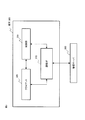
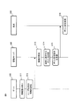
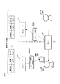
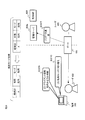
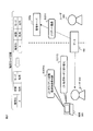
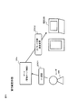
- FIG. 1 is a system configuration diagram for explaining the schematic operation of the management system according to the first embodiment of the present invention.
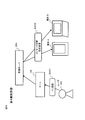
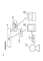
- FIG. 2 is a block diagram showing a functional configuration of the management server according to the first embodiment.
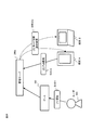
- FIG. 3 is a block diagram illustrating a functional configuration of the communication terminal according to the first embodiment.
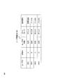
- FIG. 4 is a schematic diagram showing an example of information stored in the user information database in the management server shown in FIG.
- FIG. 5 is a schematic diagram showing another example of information stored in the user information database of the management server in the management server shown in FIG.
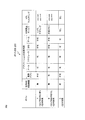
- FIG. 6 is a schematic diagram showing an example of a policy database in the management server shown in FIG.
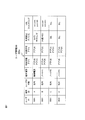
- FIG. 7 is a schematic diagram showing an example of information including usage restrictions stored in the user information database in the management server shown in FIG.
- FIG. 1 is a system configuration diagram for explaining the schematic operation of the management system according to the first embodiment of the present invention.
- FIG. 2 is a block diagram showing a functional configuration of the management server according to the first embodiment.
- FIG. 8 is a schematic diagram showing another example of information including usage restrictions stored in the user information database in the management server shown in FIG.
- FIG. 9 is a sequence diagram showing the overall operation of the management system shown in FIG.
- FIG. 10 is a schematic diagram showing an example of information setting in the user information database in the management server shown in FIG.
- FIG. 11 is a schematic diagram showing another example of information setting in the user information database in the management server shown in FIG.
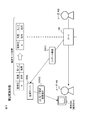
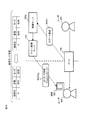
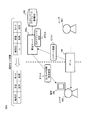
- FIG. 12 is a system configuration diagram for explaining a first operation example when a terminal moves from outside the company to the office in the management system according to the second embodiment of the present invention.
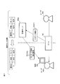
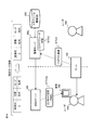
- FIG. 13 is a system configuration diagram for explaining a second operation example when the terminal moves from outside the company to the company in the management system according to the second embodiment.
- FIG. 14 is a system configuration diagram for explaining a third operation example when the terminal moves from outside the company to the company in the management system according to the second embodiment.
- FIG. 15 is a system configuration diagram for explaining a fourth operation example when the terminal moves from outside the company to the company in the management system according to the second embodiment.
- FIG. 16 is a system configuration diagram for explaining a fifth operation example when the terminal moves from outside the company to the company in the management system according to the second embodiment.
- FIG. 17 is a system configuration diagram for explaining a first operation example when a terminal moves from the inside of the company to the outside of the management system according to the second embodiment.
- FIG. 18 is a system configuration diagram for explaining a second operation example when the terminal in the management system according to the second embodiment moves from inside the company to outside the company.
- FIG. 19 is a system configuration diagram for explaining a third operation example when the terminal moves from the in-house to the outside in the management system according to the second embodiment.
- FIG. 20 is a system configuration diagram for explaining a fourth operation example when the terminal moves from the inside of the company to the outside of the management system according to the second embodiment.
- FIG. 21 is a system configuration diagram for explaining a fifth operation example when the terminal moves from the in-house to the outside in the management system according to the second embodiment.
- FIG. 22 is a system configuration diagram for explaining a first operation example when a terminal moves from outside the company to the office in the management system according to the third embodiment of the present invention.
- FIG. 23 is a system configuration diagram for explaining a second operation example when the terminal moves from outside the company to the company in the management system according to the third embodiment.
- FIG. 24 is a system configuration diagram for explaining a third operation example when the terminal moves from outside the company to the company in the management system according to the third embodiment.
- FIG. 25 is a system configuration diagram for explaining a first operation example when the terminal in the management system according to the third embodiment moves from inside the company to outside the company.
- FIG. 26 is a system configuration diagram for explaining a second operation example when a terminal moves from the in-house to the outside in the management system according to the third embodiment.
- FIG. 27 is a system configuration diagram for explaining a third operation example when the terminal moves from the in-house to the outside in the management system according to the third embodiment.
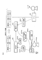
- FIG. 28 is a system configuration diagram for explaining the schematic operation of the management system according to the fourth embodiment of the present invention.
- FIG. 24 is a system configuration diagram for explaining a third operation example when the terminal moves from outside the company to the company in the management system according to the third embodiment.
- FIG. 25 is a system configuration diagram for explaining a first operation example when the terminal in the management system according to
- FIG. 29 is a system configuration diagram showing an example of a management system according to the fourth embodiment.
- FIG. 30 is a system configuration diagram for explaining the schematic operation of the management system according to the fifth embodiment of the present invention.
- FIG. 31 is a system configuration diagram for explaining the schematic operation of the management system according to the sixth embodiment of the present invention.
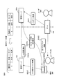
- FIG. 32 is a block diagram showing a functional configuration of the management server according to the seventh embodiment of the present invention.
- FIG. 33 is a system configuration diagram showing a first example of a management system according to the seventh embodiment.
- FIG. 34 is a system configuration diagram showing a second example of the management system according to the seventh embodiment.
- FIG. 35 is a block diagram showing a functional configuration of the management server according to the eighth embodiment of the present invention.
- the management server Change policy settings suitable for in-house or external use, or in-time or out-of-hour use for the terminal.
- Policy settings suitable for in-house use include, for example, restrictions on the use of devices such as terminal-equipped cameras, and restrictions on the use of specific applications.
- Policy settings suitable for external use include, for example, use restrictions for business applications and prohibition of access to business data.
- the management server can set an appropriate policy according to the user's whereabouts to the terminal owned by the user through the user's gate passage. Therefore, it is possible to use a private terminal for business without changing the function of the terminal owned by the user.
- the management system includes a gate 100, a management server 200, and a terminal 300, and the terminal 300 is owned by a user 400.
- the user 400 moves inside or outside the company through the gate 100.
- the gate 100 may be an existing entrance / exit determination device that is installed in the company to which the user belongs and can determine whether the user enters the company or leaves the company. For example, the user owns an employee ID card (ID card, IC card) having a non-contact IC function, and the user authentication is performed by bringing the employee ID card close to or in contact with the gate 100. Can pass through.
- the gate 100 may have a function of opening / closing a flapper gate (paddle gate) and a function of unlocking a door according to a user authentication result. Further, the gate 100 can include a biometric authentication function.
- the management server 200 manages the status of each user (internal / external), the operating status of the terminal owned by each user, the policy set for the terminal, and the like. As will be described later, the management server 200 can control the operation mode of the terminal 300 in cooperation with the existing gate 100.
- the management server 200 may be, for example, an MDM (Mobile Device Management) server. The management server 200 will be described later.
- the terminal 300 is a private terminal owned by the user 400.
- Examples of the terminal 300 include a mobile phone including a smartphone, a tablet terminal, and a notebook PC (Personal Computer). The terminal 300 will be described later.
- the management server 200 includes a control unit 201, a user information DB (Data Base) 202, a policy DB 203, and a communication interface (hereinafter referred to as I / F) 204.
- the control unit 201 receives the information of the user who has passed through the gate 100 via the communication I / F 204, the control unit 201 searches the user information DB 202 and the policy DB 203 using the user information, and transmits the information to the terminal 300 of the user who has passed through the gate 100. Determine the policy to be set.
- the control unit 201 can be realized by executing a policy setting control program on a processor.
- the user information DB 202 is a database that stores user information registered in advance
- the policy DB 203 is a database that stores policy information set in the terminal.
- the user information DB 202 and policy DB 203 will be described later.
- the communication I / F 204 is a communication interface for communicating with the gate 100 and the terminal 300, and can receive user information from the gate 100 and transmit / receive terminal information and policy setting information to / from the terminal 300. it can.
- the terminal 300 includes a communication I / F 310, a client 320, and a control unit 330.
- the communication I / F 310 is an interface for communicating with the management means such as the management server 200, an SMS (Short Message Service) server, and a push delivery server, which will be described later.
- the client 320 is a function realized by a client program executed on the processor, and executes policy setting by interpreting the setting instructed from the management server 200 or the like or a command to be set.
- the policy set in the terminal 300 may be registered in the client 320 in advance. Further, even if the policy is not registered in the client 320, application or device usage restrictions can be set as appropriate, as will be described later in the embodiments.
- the control unit 303 is a processor that controls the overall operation of the terminal 300, and controls the operation of the terminal 300 in accordance with the policy set by the client 320.
- the user information DB 202 illustrated in FIG. 4 stores a user ID, a terminal ID owned by the user, a user status, a policy set in the terminal, and a terminal type.
- the user ID is an identifier that can identify an individual such as an employee number.
- the terminal ID may be an identifier that can identify the terminal, and for example, a MAC (Media Access Control) address may be used.
- the user with the user ID “0001” (hereinafter referred to as the user 0001) is in the company and owns two different terminals with terminal IDs “A” and “B”.
- the terminal type as described later, it is only necessary to determine whether a cellular network such as 3G or LTE (LongLTerm Evolution) can be used. Therefore, the user information DB 202 may store information as to whether each terminal can use the cellular network, as shown in FIG. In the example of FIG.
- terminal A only the terminal A is a mobile phone and can use a cellular network. Since other terminals are notebook PCs, it turns out that a cellular network cannot be used. Different policies can be set for each terminal. 4 and 5, policy A is set for terminal A, and policy B is set for terminal B.
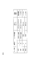
- the policy DB 203 illustrated in FIG. 6 stores policy information such as presence / absence of connection restriction to an in-house network and availability of applications installed in each terminal.
- policy A is a policy that is set when a terminal that can use a cellular network (here, a mobile phone) is used in-house. There is no restriction on the connection to the internal network because it is the use of the mobile phone in the company, but it is “impossible” to access the portal site prepared by the company and use the business application.
- applications such as e-mail and scheduler can be used, but SNS (Social Network Service) and game related applications are not permitted.
- SNS Social Network Service
- game related applications are not permitted.
- policy A since policy A is supposed to be used in-house for mobile phones, device functions such as camera and tethering can be prohibited, and URL filtering can be set to restrict access to specific websites.
- Policy B is a policy that is set when a terminal (in this case, a notebook PC) that cannot use the cellular network is used in-house.
- Policy B has the same settings as e-mail, scheduler, SNS, game, etc., but differs from policy A in that the use of business applications is permitted only when the user is in the office.
- use of an external memory such as a USB memory can be prohibited.
- Policy C is a policy set in the terminal when the user is outside the company, and can be set regardless of the type of mobile phone, notebook PC, or the like. Policy C is a policy when the user is outside the company, so use of business applications is “impossible”, use of SNS and games is “possible”, and device functions and URL filtering that are prohibited from use are also "none" Set to
- the user information DB 202a stores information for managing usage restrictions and the like of applications and devices for each terminal.
- Use of device functions such as camera and tethering and access to specific websites are prohibited.
- the information stored in the user information DB 202a is basically the same as the user information shown in FIGS. 4 and 5 plus the policy information shown in FIG.
- the “terminal type” in FIG. 7 may be stored as information indicating whether or not the cellular network can be used (corresponding to cellular). Except for whether or not the cellular network is supported, the information is the same as that shown in FIG.
- Application usage restrictions can be set by a blacklist method for setting prohibited applications or a whitelist method for setting available applications.
- Time restrictions such as the time for distributing applications and the time for executing applications can be set in the terminal in advance.
- Terminal operation restriction / data initialization Instruct the terminal to perform remote lock or local lock to make the terminal inoperable (locked), and / or remote wipe to initialize or erase terminal data be able to.
- the device functions of the terminal can be made available or unavailable.
- Examples of the device function include a short-range wireless communication such as a camera and Bluetooth (registered trademark), a wireless LAN interface, an external memory, a tethering function, a screen capture function, and the like.
- the call destination can be restricted. For example, when a terminal is used for business, it is possible to limit the destinations that can be called to only the destinations related to the business.
- the terminal can be set to perform virus scan, malware scan, etc. At that time, for example, the time for which the terminal performs scanning can be set.
- the terminal can be set to switch the home screen according to the mode / policy to be set. For example, when a policy to be set during business use is set, only applications used in business can be displayed. Conversely, when a policy to be set outside business hours is set, it is possible to set so that applications used in business are not displayed.
- the policies set in the terminal 300 are limited to two, “in-house” or “private”.
- the “in-house” policy is a policy set in the terminal 300 when it is determined that the user 400 who owns the terminal 300 is in the office (in the office).
- the “private” policy is a policy set in the terminal 300 when it is determined that the user who owns the terminal 300 is outside the office (outside the office). In practice, it is possible to create a policy by combining not only two policies but also various controls such as the above-described usage restrictions on applications and devices.
- the gate 100 reads information from the user's IC card by bringing the IC card such as an employee card close to or in contact with the gate 100 (operation S11). .
- the information read by the gate 100 includes, for example, a user ID.
- the gate 100 recognizes that the user status is “internal” when the user enters the company, and confirms that the user status is “external” when the user leaves the company. recognize. Further, depending on the user authentication result at the gate 100, the gate may be opened and closed, the door unlocked, or the like.
- the gate 100 transmits the read information (user ID) and the user status (internal or external) changed by the user passing through the gate 100 to the management server 200 (operation S12).
- the management server 200 When receiving the user information from the gate 100, the management server 200 first searches whether the corresponding user is registered in the user information DB 202 (operation S13). If the user is not registered in the user information DB 202 as a result of the search, it is determined that the user is a user who is not permitted to BYOD, and no policy setting is performed on the terminal owned by the user.
- the terminal owned by the user is identified, the user status is changed, the user status (internal / external), the terminal type (cellular network compatible /
- the policy to be set in the terminal owned by the user is determined based on (not supported) or the like (operation S14), and the policy setting instruction is transmitted to the terminal 300 (operation S15).
- the terminal 300 changes the policy setting as instructed (operation S16). This setting change is performed by, for example, client software installed in the terminal 300 in advance. Note that the management server 200 can directly change the policy of the terminal 300.
- the method for transmitting the policy setting instruction from the management server 200 to the terminal 300 differs depending on the type of the terminal, whether it can be connected to the cellular network, and the like.
- the method for sending a policy using SMS Short Message Service
- a method of sending a policy to the terminal 300 using a push delivery server and the like.
- user 0001 the user information DB 202
- the case where it has moved will be described as an example.
- the management server 200 searches the user information DB 202 and identifies the user 0001 (operation S13). Subsequently, the management server 200 changes the state of the user 0001 from “internal” to “external”, and further searches the policy DB 203 and applies the policy applied to the terminals A and B of the user 0001 in the user information DB 202 to the internal policy A. To external policy C (operation S14). In this case, since the movement is outside the company, the policy C is applied regardless of the type of the terminal. Then, the management server 200 transmits the policy C setting instruction to the terminals A and B (operation S15), and the terminals A and B that have received the policy setting change instruction apply their operations to the policy C applied to the external terminal. (Operation S16).
- user 0002 0002 (hereinafter referred to as “user 0002”), and this user 0002 passes through the gate 100 and moves from outside the company to the company. This will be described as an example.
- the management server 200 searches the user information DB 202 to identify the user 0002 (operation S13). Subsequently, the management server 200 changes the status of the user 0002 from “external” to “internal”, and further searches the policy DB 203 to apply a policy to be applied to the terminal C of the user 0002 in the user information DB 202 from the external policy C to the internal policy. Change to policy B (operation S14). In this case, since the terminal B is a movement of the notebook PC that cannot use the cellular network into the office, the policy set in the office is the policy B as described with reference to FIG. Then, the management server 200 transmits the policy B setting instruction to the terminal C (operation S15), and the terminal C that has received the policy setting change instruction changes its own operation to the policy B (operation S16).
- the gate 100 that is an existing user entrance / exit determination device and the management server 200 that manages the terminal are linked to each other to prevent the terminal from being connected.
- the terminal that can use the cellular network corresponds to a terminal whose “terminal type” is “mobile phone” shown in FIG. 4 or a terminal whose “cellular correspondence” is “Yes” shown in FIG. Specifically, as described in the first embodiment, for example, a mobile phone or a mobile terminal that can access 3G and LTE.
- terminals are assumed to be registered in advance in the management server, and for the policies, as in the first embodiment, “in-house” and “private” policies according to the terminal types illustrated in FIG. 6 are adopted.
- the same constituent elements as those in the first embodiment are denoted by the same reference numerals as in FIG. 1, and the case where the user moves from outside the company (FIGS. 12 to 16) and the case where the user moves outside the company (FIG. 17). To FIG. 21).
- Mode switching example I by push communication When the management server detects that the user has passed through the gate, the management server directly instructs the terminal owned by the user to switch the mode from outside to inside the company.
- the user status and mode information corresponding to the terminal A stored in the user information DB 202 is updated to “in-house”.
- the terminal 300 Upon receiving the mode setting change instruction, the terminal 300 changes the setting policy from “private” to “in-house”.
- the policy information to be set may be stored in advance in the terminal 300 and switched according to the mode setting change instruction, or the policy information itself may be received from the management server 200a.
- the setting is changed from policy C to policy A shown in FIG.
- the policy shown in FIG. 6 is only an example, and as described in the first embodiment, it is possible to create a policy by combining various controls such as usage restrictions on applications and devices.
- the management system shown in FIG. 13 includes an SMS server 500 in addition to the system configuration shown in FIG.
- the SMS server 500 is, for example, a server owned by a communication carrier, and can transmit SMS to a terminal contracted with the carrier.
- the user status and mode information corresponding to the terminal A stored in the user information DB 202 is updated to “in-house”.
- the terminal 300 that has received the mode setting change instruction SMS analyzes the SMS and changes the setting policy from “private” to “in-house”.
- the policy information to be set may be stored in advance in the terminal 300 and switched according to the mode setting change instruction.
- the setting is changed from policy C to policy A shown in FIG.
- the management server When the management server detects that the user has passed through the gate, the management server transmits a mode switching instruction or a mode setting instruction to the terminal through the push delivery server.
- the push delivery server may be installed inside or outside the company, or may be a server owned by a company to which the user 400 belongs.
- the management system shown in FIG. 14 has a configuration in which a push delivery server 510 is arranged instead of the SMS server 500 of the system shown in FIG.
- the push delivery server 510 may be a server having a function of sending a message to the terminal 300.
- the push delivery server 510 sends a push message related to mode switching or policy setting of the terminal 300. Can do. Since there is no significant difference from the system of FIG. 13 except that the SMS server 500 is changed to the push delivery server 510, description of the configuration and operation is omitted.
- the management system shown in FIG. 15 is the same as the system configuration including the SMS server shown in FIG. 13, but the operations of the management server 200c and the terminal 300 are different.
- the identification information of the user 400 is notified from the gate 100 to the management server 200c as already described (operation S201).
- the management server 200c requests the SMS server 500 to send an SMS for the terminal 300 to request authentication.
- the SMS server 500 that has received the request requests the terminal 300 to transmit the SMS and perform authentication (operation S203).
- the terminal 300 Upon receiving the request message from the SMS server 500, the terminal 300 issues an authentication request to the management server 200c (operation S204).
- the management server 200c instructs the terminal 300 to switch the terminal mode or change the policy setting (operation S202c), whereby the policy of the terminal 300 is changed to the “in-house” policy.
- the terminal 300 Upon receiving the mode setting change instruction, the terminal 300 changes the setting policy from “private” to “in-house”.
- the policy information to be set may be stored in advance in the terminal 300 and switched according to the mode setting change instruction, or the policy information itself may be received from the management server 200a.
- the setting is changed from policy C to policy A shown in FIG.
- the push distribution server 510 can also be used.
- the management server detects pull type communication from a terminal after detecting a user's passage through the gate, it instructs mode switching or mode setting after the terminal is authenticated.
- the terminal performs pull-type communication with the management server when the client is activated.
- the identification information of the user 400 is notified from the gate 100 to the management server 200d as described above. (Operation S201).
- the terminal 300 performs pull-type communication with the management server 200d (operation S206). Specifically, the terminal 300 inquires of the management server 200d whether there is a mode setting change.
- the management server 200d Upon receiving the pull-type communication from the terminal 300, the management server 200d authenticates the terminal 300. When the authentication is successful, the management server 200d instructs the terminal 300 to switch the mode or change the policy setting (operation S202d). With the above operation, the policy of the terminal 300 is changed to the “in-house” policy.
- the pull-type communication is performed by the terminal 300 when the client of the terminal 300 is activated, but the same pull-type communication may be performed when the terminal 300 is turned on.
- FIG. 17 shows an example of mode switching by push type communication corresponding to FIG.
- the management server 200e detects that the user 400 passes the gate 100 and goes outside (operation S201)
- the management server 200e directly instructs the terminal 300 to switch to the outside mode (operation S202e).
- An instruction from the management server 200e to the terminal 300 can be transmitted through the cellular network.
- the user status and mode information corresponding to the terminal A stored in the user information DB 202 are updated to “external” and “private”, respectively.
- the terminal 300 Upon receiving the mode setting change instruction, the terminal 300 changes the setting policy from “internal” to “private”.
- the policy information to be set may be stored in advance in the terminal 300 and switched according to the mode setting change instruction, or the policy information itself may be received from the management server 200a.
- the setting is changed from policy A to policy C shown in FIG. 6, for example.
- the policy shown in FIG. 6 is an example, and as described in the first embodiment, it is possible to create a policy by combining various controls such as application and device usage restrictions.
- FIG. 18 shows an example of mode switching by push type communication corresponding to FIG.
- the management server 200f detects that the user 400 passes the gate 100 and goes outside (operation S201)
- the management server 200f transmits a mode switching instruction or mode setting instruction message to the terminal 300 through the SMS server 500 (operation S202f).
- the SMS server 500 is installed outside the company.
- FIG. 19 shows an example of mode switching by push type communication corresponding to FIG.
- the management server 200g detects that the user 400 passes the gate 100 and goes outside (operation S201)
- the management server 200g transmits a push message indicating mode switching or mode setting to the terminal 300 through the push delivery server 510 (step S201).
- Operation S202g Operation S202g).
- the push delivery server 510 can be installed outside or inside the company.
- FIG. 20 shows an example of mode switching by push type communication corresponding to FIG.
- the management server 200h detects that the user 400 has passed through the gate (operation S201)
- the management server 200h transmits a message requesting the terminal 300 to make an authentication request through the SMS server 500 (or a push distribution server) (operation S207).
- the management server 210h instructs the terminal 300 to perform mode switching or mode setting (operation S202h).
- FIG. 21 shows an example of mode switching by pull-type communication corresponding to FIG.
- the management server 200i detects that the user 400 has passed through the gate (operation S201)
- the management server 200i then waits for pull-type communication from the terminal 300.
- the client is activated on the terminal 300 (operation S209) and there is pull-type communication (operation S210)
- the management server 200i instructs mode switching or mode setting after the terminal 300 is authenticated (operation S202i).
- a management system that issues a policy setting instruction to a terminal that cannot use a cellular network will be described as a third embodiment of the present invention. Since the internal configurations of the management server and the terminal are basically the same as the configurations shown in FIGS. 2 and 3, the description thereof will be omitted, and operations different from those of the first embodiment will be mainly described.
- the terminal that cannot use the cellular network corresponds to a terminal whose “terminal type” is “notebook PC” shown in FIG. 4 or a terminal whose “cellular correspondence” is “No” shown in FIG.
- a notebook PC or a tablet terminal that does not have an access function in 3G or LTE.
- terminals are assumed to be registered in advance in the management server, and for the policies, as in the first embodiment, “in-house” and “private” policies according to the terminal types illustrated in FIG. 6 are adopted.
- the same constituent elements as those in the first embodiment are denoted by the same reference numerals as in FIG. 1, and the case where the user moves from outside the company (FIGS. 22 to 24) and the case where the user moves outside the company (FIG. 25). 27 to FIG. 27).
- the management server detects pull-type communication from a terminal after detecting the user's gate passage, the management server instructs mode switching or mode setting after authentication of the terminal.
- the terminal performs pull-type communication with the management server when the client is activated.
- the identification information of the user 400 is notified from the gate 100 to the management server 200j as described above. (Operation S301).
- the terminal 300 performs pull-type communication with the management server 200j (operation S303). Specifically, the terminal 300 inquires of the management server 200j whether or not there is a mode setting change.
- the management server 200j Upon receiving the pull-type communication from the terminal 300, the management server 200j authenticates the terminal 300. When the authentication is successful, the management server 200j instructs the terminal 300 to change the mode or change the policy setting (operation S304). With the above operation, the policy of the terminal 300 is changed to the “in-house” policy. Here, since the terminal 300 is a terminal that cannot use the cellular network, the policy C is switched to the policy B shown in FIG.
- the pull-type communication is performed by the terminal 300 when the client of the terminal 300 is activated, but the same pull-type communication may be performed when the terminal 300 is turned on.
- the identification information of the user 400 is notified from the gate 100 to the management server 200k as described above. (Operation S301).
- the terminal 300 makes a connection request to the in-house access point 600 and connects to the in-house access point 600 (operation S305).
- a setting-specific or guest SSID Service Set Identifier
- the in-house access point 600 authenticates the connected terminal 300 (operation S306), and when the authentication is successful, transmits the information of the terminal 300 to the management server 200k.
- the management server 200k instructs the terminal 300 that has passed through the gate and is authenticated to change the mode or change the policy setting (operation S304a).
- the policy of the terminal 300 is changed to the “in-house” policy.
- the policy C is switched to the policy B shown in FIG.
- the identification information of the user 400 is notified from the gate 100 to the management server 200k as described above. (Operation S301).
- the terminal 300 accesses and connects to the authentication site of the authentication server 700 (operation S307).
- the authentication server 700 authenticates the connected terminal 300.
- the authentication server 700 transmits an authentication notification of the terminal 300 to the management server 200m (operation S308).
- the management server 200m instructs the terminal 300 to switch the mode or change the policy setting (operation S304b).
- the policy of the terminal 300 is changed to the “in-house” policy.
- the policy C is switched to the policy B shown in FIG.
- Mode switching example I when moving from inside to outside the company
- the management server receives the authentication notification of the terminal from the authentication server after detecting that the user has passed through the gate, the management server instructs the terminal to switch the mode or set the mode.
- the terminal connects to the authentication server when the client is activated. This terminal cannot be connected to the in-house intranet or the cellular network.
- the identification information of the user 400 is transferred from the gate 100 to the management server 200n. (Operation S301).
- the terminal 300 accesses and connects to the authentication site of the authentication server 700 (operation S307).
- the authentication server 700 authenticates the connected terminal 300.
- the authentication server 700 transmits an authentication notification of the terminal 300 to the management server 200n (operation S308).
- the management server 200n instructs the terminal 300 to switch the mode or change the policy setting (operation S304c).
- the policy of terminal 300 is changed to the “private” policy.
- the policy B is switched to the policy C shown in FIG.
- the management server 200p is not involved in mode switching of the terminal 300.
- the terminal 300 determines whether or not the SSID from the in-house access point 600 can be detected (operation S309). If the SSID cannot be detected, the terminal 300 determines that it has gone out of the office and switches its own policy to the private mode (operation S310).
- the policy of terminal 300 is switched from policy B to policy C shown in FIG.
- the client activation of the terminal 300 may be automatically executed at a predetermined cycle, or may be activated by the user 400.
- Example of mode switching when moving from inside to outside the company III In the mode switching example III, as in the mode switching example II described above, the terminal mode switching is not the management server but the terminal itself switches the policy from “in-house” to “private”, but the criterion is set in advance. It is different in that it is a time standard whether or not it is within working hours.
- the management server 200p is not involved in mode switching of the terminal 300.
- the terminal 300 determines whether or not the current time is within a preset working time (operation S309a). If it is outside the working hours, the terminal 300 determines that it has gone out of the office and switches its own policy to the private mode (operation S310).
- the policy of terminal 300 is switched from policy B to policy C shown in FIG.
- the management server when a user who owns a plurality of terminals passes through the gate, for example, when entering the company or going out of the company, the management server sends each terminal
- the policy setting suitable for in-house or outside use or use within a predetermined time or outside a predetermined time is changed.
- policy settings suitable for in-house use include, for example, usage restrictions on devices such as terminal-mounted cameras, usage restrictions on specific applications, and the like.
- Policy settings suitable for external use include, for example, use restrictions for business applications and prohibition of access to business data.
- different policies may be set depending on whether or not the cellular network is supported, as well as inside / outside.
- the management server can set an appropriate policy for each of a plurality of terminals owned by the user according to the user's whereabouts, current time and / or cellular network support / non-support by passing through the gate of the user.
- a plurality of user-owned terminals need not be carried by the user. For example, even when a user carries one terminal and the other terminal is in the office, the management server can set an appropriate policy.
- the present invention as in the above-described embodiment, a case where the present invention is applied to an office of a company will be described, but the present invention is not limited to this.
- this embodiment can be applied not only to a company but also to a school or the like.
- the management system and the management server according to the fourth embodiment will be described in detail with reference to the drawings.
- the internal configurations of the management server and the terminal are basically the same as the configurations shown in FIGS. 2 and 3, operations different from those in the first embodiment will be mainly described.
- the management system includes a gate 100, a management server 200r, and terminals A and B owned by a user 400.
- the user 400 moves inside or outside the company through the gate 100.
- the gate 100 may be an existing entrance / exit determination device that can determine whether the user enters the company or leaves the company. Depending on the authentication result of the user, the gate 100 may be a paddle gate. , Flapperer gate) and a function to unlock the door may be provided. Further, the gate 100 can include a biometric authentication function.
- the management server 200r manages the status of each user (internal / external), the operating status of the terminal owned by each user, the policy set for the terminal, and the like.
- the management server 200r can control the operation mode of each terminal in cooperation with the existing gate 100.
- the management server 200r transmits an instruction to switch the setting policy of the terminal A and the terminal B, which are privately owned by the user 400, to the in-house use mode (Operation S402).
- the user status and mode information corresponding to terminal A and terminal B stored in the user information DB 202 are updated to “in-house”.
- terminal A and terminal B Upon receiving the mode setting change instruction, terminal A and terminal B change the setting policy from “private” to “in-house”.
- the policy information to be set is stored in advance in each terminal and may be switched according to the mode setting change instruction, or the policy information itself may be received from the management server 200r.
- the terminal A can use the cellular network
- the setting is changed from the policy C shown in FIG. 6 to the policy A, for example.
- the terminal B cannot use the cellular network, the policy is changed from the policy C to the policy B shown in FIG.
- the setting is changed to
- the policy shown in FIG. 6 is only an example, and as described in the first embodiment, it is possible to create a policy by combining various controls such as usage restrictions on applications and devices.
- the management server detects that a user has passed through the gate, the management server sends a pull-type communication from at least one of a plurality of terminals owned by the user to a terminal owned by the user. Instruct the mode switching from outside to inside the company respectively.
- terminals A and B owned by the user 400 are registered in advance in the management server.
- the management server 200s Upon receiving the pull-type communication from the terminal A, the management server 200s searches for another terminal B of the user who owns the terminal A, and instructs the terminals A and B to switch the mode or change the policy setting. (Operation S402a). With the above operation, the policies of the terminals A and B owned by the user 400 are changed to the “in-house” policy. As described above, since the terminal A can use the cellular network, for example, the setting is changed from the policy C shown in FIG. 6 to the policy A, and since the terminal B cannot use the cellular network, for example, from the policy C shown in FIG. The setting is changed to policy B.
- the gate and the management server are separated, but a management server function may be mounted on the gate.
- the management system has the above-described function of the management server 200 mounted on the gate 100a, and when the user 400 passes through the gate 100a (operation S501), the management server function is An instruction to switch the setting policy of the terminal 300 that is private to the user 400 to the in-house use mode is transmitted using the identification information of the user 400 (operation S502). Since the gate function and management server function of the gate 100a are the same as those already described, description thereof will be omitted.
- the gate 100 is used as a user entrance / exit determination device, but the present invention is not limited to this.
- a specific terminal may be caused to function as a user determination device that determines whether a user leaves or leaves the company.
- the management system includes a management server 200t, a terminal 300A functioning as a user determination device, and a terminal 300B owned by the user 400.
- the user 400 may be the owner of both the terminal 300A and the terminal 300B, it is assumed here that the user 400 is the owner of only the terminal 300B.
- the terminal 300A authenticates the user 400 (operation S601). If the authentication is successful, the terminal 300A performs pull-type communication with the management server 200t (operation S602).
- the management server 200t Upon receiving the pull-type communication from the terminal 300A, the management server 200t searches for the terminal 300B owned by the user 400 and instructs the terminal 300B to switch the mode or change the policy setting (operation S603). With the above operation, the policy of the terminal 300B owned by the user 400 is changed to the “in-house” policy.
- the terminal 300A needs to be equipped with a non-contact type IC reader and a pull communication function to the management server 200t, but the other terminal 300B performs the mode switching control as in the above-described embodiment. be able to.
- the user's entry / exit is determined using the gate 100 or a terminal as a user determination device, but the present invention is not limited to this. According to the seventh embodiment of the present invention, not only spatial user status determination by the gate 100 but also mode switching by temporal user status determination in cooperation with the in-house schedule system is possible.
- the management server 200u includes a control unit 201, a user information DB 202 including policy information, a communication interface 204, and a schedule management database 205.
- the basic operation of the management server 200u is the same as that of the management server 200 according to the first embodiment, except that the policy switching control is performed with reference to the schedule management database 205.
- the schedule management database 205 stores, for example, user (employee) schedule information (outing time zone, outing place, etc.), access time zone from the destination to the in-house PC, and the like.
- user employee
- schedule information outing time zone, outing place, etc.
- access time zone from the destination to the in-house PC, and the like.
- the management server 200u can refer to the schedule of the user 400 in cooperation with the in-house schedule management database 205.
- the management server 200u detects that the user 400 has passed the gate 100 and went outside (operation S701), the management server 200u refers to the schedule management database 205, and the current time is the pre-registered schedule time of the user 400. It is determined whether it is within (for example, “9: 00-11: 00 is going out”) (operation S702).
- the management server 200u directly instructs the terminal 300 to switch to the outside mode (operation S703).
- the user status and mode information corresponding to the terminal A (terminal 300) stored in the user information DB 202 is updated to “external” and “private”, respectively.
- the terminal 300 Upon receiving the mode setting change instruction, the terminal 300 changes the setting policy from “in-house” to “private”.
- the policy information to be set may be stored in advance in the terminal 300 and switched according to the mode setting change instruction, or the policy information itself may be received from the management server 200u.
- the management server 200u changes the mode to an in-house policy or a policy that is less restrictive even if the user 400 leaves the gate 100 within the schedule time, and uses the terminal 300 in the in-house mode or the semi-in-house mode. enable.
- a mode switching instruction or a mode setting instruction can be transmitted to the terminal 300 through the SMS server 500 (operation S703a).
- mode switching control at the time of moving outside the company may be executed.
- the target of mode switching control may be a plurality of terminals.
- the mode switching of another terminal B of the user can be executed by installing the employee card function in the terminal A having the wireless LAN function.
- the terminal A for example, a terminal having a tethering function can be used.
- the user 400 moves through the gate 100 by bringing the terminal A having the employee card function and the wireless LAN function close to the gate 100 (operations). S801).
- the terminal A transmits an instruction to switch the setting policy of the terminal B owned by the user 400 through the wireless LAN (operation S802).
- the setting policy of the terminal B owned by the user can be directly changed without authentication by the management server.
- (Appendix 1) A management system for managing terminals owned by users, An entrance / exit determination device for determining entrance / exit for a predetermined location of the user; A management device that determines an operation policy based on at least a determination result by the entrance / exit determination device, and sets the determined operation policy in a terminal owned by the user; A management system comprising: (Appendix 2) The management system according to appendix 1, wherein the entrance / exit determination device determines the entrance / exit by user identification means other than the terminal.
- the supplementary note 1-8 wherein the management device transmits a policy change message to the terminal through a short message service (SMS) server, and the terminal changes an operation policy according to the policy change message.
- SMS short message service
- the management system described. The management apparatus transmits the policy change command to the terminal in response to an authentication request from the terminal that has received the policy change message through a short message service (SMS) server.
- SMS short message service
- the terminal performs the determined operation in accordance with a policy change command from the management device after authentication at an access point provided in the predetermined location or an authentication server provided in the predetermined location or outside the predetermined location. 9. The management system according to any one of appendices 1-8, wherein a policy is set.
- the management apparatus further determines the operation policy according to a schedule of the user registered in advance, and sets the determined operation policy in a terminal owned by the user.
- the management apparatus determines an operation policy corresponding to the predetermined location within the schedule time even if the user is outside the predetermined location, and the user owns the determined operation policy.
- (Appendix 16) A management method for managing a terminal owned by a user, The entrance / exit determination device determines the entrance / exit for the predetermined location of the user, The management device determines an operation policy based on at least the determination result by the entrance / exit determination device, and sets the determined operation policy in a terminal owned by the user. A management method characterized by that.
- (Appendix 17) The management method according to appendix 16, wherein the entrance / exit determination device determines the entrance / exit by user identification means other than the terminal.
- (Appendix 19) The management method according to any one of appendices 16-18, wherein the management device sets the operation policy for a plurality of terminals owned by the user.
- (Appendix 20) 20 The management method according to any one of appendices 16-19, wherein the management device determines an operation policy with different function restrictions depending on whether or not the terminal is compatible with a cellular network.
- (Appendix 21) The management method according to appendix 19 or 20, wherein the management device sets the operation policy in the plurality of terminals in response to a request from one of the plurality of terminals.
- (Appendix 22) The management method according to any one of appendix 16-21, wherein the entrance / exit determination device is a gate having an authentication function of the user.
- the management apparatus transmits the policy change command to the terminal in response to an authentication request from the terminal that has received the policy change message through a short message service (SMS) server.
- SMS short message service
- the management method according to any one of the above.
- the terminal performs the determined operation in accordance with a policy change command from the management device after authentication at an access point provided in the predetermined location or an authentication server provided in the predetermined location or outside the predetermined location. 24.
- the management method according to any one of appendix 16-23, wherein a policy is set.
- the management apparatus further determines the operation policy according to a user schedule registered in advance, and sets the determined operation policy in a terminal owned by the user.
- the management apparatus determines an operation policy corresponding to the predetermined location within the schedule time even if the user is outside the predetermined location, and the user owns the determined operation policy.
- a management server that manages terminals owned by users, Policy determining means for determining an operation policy of a terminal owned by the user based on user information including at least a determination result from an entrance / exit determination device for determining entrance / exit for a predetermined place of the user; Communication control means for notifying the determined operation policy information to a terminal owned by the user;
- a management server characterized by comprising: (Appendix 32) The management server according to appendix 31, wherein the entrance / exit determination device determines the entrance / exit by user identification means other than the terminal. (Appendix 33) 33.
- the management server according to appendix 31 or 32, wherein the policy determination means sets the operation policy to a plurality of terminals owned by the user.
- (Appendix 34) 34 The management server according to any one of appendices 31 to 33, wherein the policy determining means determines an operation policy with different function restrictions depending on whether or not the terminal is compatible with a cellular network. . (Appendix 35) 35. The management server according to any one of appendices 31 to 34, wherein the policy determination means sets the operation policy to the plurality of terminals in response to a request from one of the plurality of terminals. (Appendix 36) 36. The management server according to any one of appendices 31 to 35, wherein the entrance / exit determination device is a gate having an authentication function of the user. (Appendix 37) 37.
- the management server according to any one of appendices 31 to 36, wherein the terminal is a client of the management server.
- the management server according to any one of appendices 31-37, wherein the communication control means transmits a policy change command to the terminal by push-type communication.
- (Appendix 39) The management server according to any one of supplementary notes 31-37, wherein the communication control means transmits a policy change command to the terminal by pull-type communication from the terminal.
- Appendix 40 Any one of appendices 31-37, wherein the communication control means transmits a policy change message to the terminal through a short message service (SMS) server, and the terminal changes an operation policy according to the policy change message.
- SMS short message service
- the communication control means transmits the policy change command to the terminal in response to an authentication request from the terminal that has received the policy change message through a short message service (SMS) server.
- SMS short message service
- the management server according to any one of the above.
- the communication control means transmits a policy change command to the terminal after the terminal is authenticated by an access point provided in the predetermined location or an authentication server provided in the predetermined location or outside the predetermined location.
- the management server according to any one of supplementary notes 31-37, wherein: (Appendix 43)
- the policy determination means further determines the operation policy in accordance with a schedule of the user registered in advance, and sets the determined operation policy in a terminal owned by the user. Management server given in any 1 paragraph.
- the policy determining means determines an operation policy corresponding to the predetermined location within the schedule time even if the user is outside the predetermined location, and the user owns the determined operation policy. 44.
- (Appendix 45) Managed by the management server in a management system comprising an entrance / exit determination device for determining entrance / exit to a predetermined location of a user and a management server for determining an operation policy based on at least a determination result by the entrance / exit determination device
- a user-owned communication terminal Policy setting means for setting an operation policy determined by the management server
- Control means for performing operation control of the communication terminal by function setting according to the operation policy
- a communication terminal comprising: (Appendix 46) 46.
- the communication terminal according to appendix 45 or 46, wherein the policy setting means sets the determined operation policy in accordance with a policy change command from the management device.
- Appendix 48 A terminal control method of a management server that manages a terminal owned by a user, The policy determining means determines an operation policy of a terminal owned by the user based on user information including at least a determination result from an entrance / exit determination device that determines entrance / exit for a predetermined location of the user, A communication control means notifies the determined operation policy information to the terminal owned by the user.
- a terminal control method for a management server A terminal control method for a management server.
- the management server terminal control method according to appendix 48, wherein the entrance / exit determination device determines the entrance / exit by user identification means other than the terminal.
- (Appendix 50) The management server terminal control method according to appendix 48 or 49, wherein the policy determination means sets the operation policy to a plurality of terminals owned by the user.
- Terminal control method. (Appendix 52) 52.
- the management server according to any one of appendices 48 to 51, wherein the policy determination means sets the operation policy to the plurality of terminals in response to a request from one of the plurality of terminals. Terminal control method. (Appendix 53) 53.
- the management server terminal control method according to any one of appendices 48 to 52, wherein the entrance / exit determination device is a gate having an authentication function of the user. (Appendix 54) 54.
- the management server terminal control method according to any one of appendices 48 to 53, wherein the terminal is a client of the management server.
- the control method in the communication terminal characterized by the above-mentioned.
- (Appendix 56) 56 The communication terminal according to appendix 55, wherein the entry / exit determination device determines the entrance / exit by user identification means other than the communication terminal.
- Appendix 58 A management system for managing terminals owned by users, An entrance / exit detection device for detecting entrance / exit to a predetermined place of the user; In response to the entry / exit detection device detecting entry / exit, a management device that notifies the terminal of the operation policy of the terminal, A management system comprising: (Appendix 59) 59.
- (Appendix 60) A management method for managing a terminal owned by a user, The entry / exit detection device detects entry / exit for the user's predetermined location, In response to the entrance / exit determination device detecting entry / exit, the management device notifies the terminal of the operation policy of the terminal, A management method characterized by that. (Appendix 61) 61. The management method according to appendix 60, wherein the management device notifies the terminal of the operation policy by a communication method that can be used by the terminal.
- (Appendix 62) A management server that manages terminals owned by users, A communication means for receiving a notification indicating that an entry / exit for a predetermined location of the user is detected from the entry / exit detection means; A control means for notifying the terminal of the operation policy of the terminal in response to the notification; A management server characterized by comprising: (Appendix 63) 63.
- a user-owned communication terminal managed by the management server A communication means for receiving an operation policy notified from the entrance / exit detection means based on the entry / exit detection result for the user's predetermined place by the management server; Control means for performing operation control of the communication terminal by function setting according to the operation policy;
- a communication terminal comprising: (Appendix 65) The communication terminal according to appendix 64, wherein the communication means receives the operation policy from the management server by a communication method usable by the communication terminal.
- a terminal control method of a management server that manages a terminal owned by a user, The communication means receives a notification from the entry / exit detection means indicating that the entry / exit for the user's predetermined place has been detected, In response to the notification, the control means notifies the terminal of the operation policy of the terminal.
- a terminal control method for a management server. (Appendix 67) 67. The terminal control method for a management server according to appendix 66, wherein the control means notifies the terminal of the operation policy by a communication method usable by the terminal.
- Appendix 68 A control method in a user-owned communication terminal managed by a management server, The communication means receives the operation policy notified by the management server, The control means performs operation control of the communication terminal by function setting according to the operation policy.
- the control method in the communication terminal characterized by the above-mentioned.
- Appendix 69 The communication terminal according to appendix 68, wherein the communication means receives the operation policy from the management server by a communication method usable by the communication terminal.
- the present invention can be applied to a system that enables business use of a private terminal.
- Control Unit 100 Gate 200 Management Server 201 Control Unit 202 User Information Database 203 Policy Database 204 Communication Interface 205 Schedule Management Database 300 Terminal 310 Communication Interface 320 Client 330 Control Unit 400 User
Landscapes
- Engineering & Computer Science (AREA)
- Computer Networks & Wireless Communication (AREA)
- Signal Processing (AREA)
- Computer Security & Cryptography (AREA)
- Human Computer Interaction (AREA)
- Computer Hardware Design (AREA)
- Computing Systems (AREA)
- General Engineering & Computer Science (AREA)
- Environmental & Geological Engineering (AREA)
- Telephonic Communication Services (AREA)
- Mobile Radio Communication Systems (AREA)
- Telephone Function (AREA)
Abstract
Description
本発明による管理方法は、ユーザが所有する端末を管理する管理方法であって、入退場検知装置が、ユーザの所定場所に対する入退場を検知し、管理装置が、前記入退場判定装置が入退場を検知したことに応じて、前記端末の動作ポリシを当該端末に通知する、ことを特徴とする。
本発明による管理サーバは、ユーザが所有する端末を管理する管理サーバであって、入退場検知手段からユーザの所定場所に対する入退場を検知したことを示す通知を受信する通信手段と、前記通知に応じて、前記端末の動作ポリシを当該端末に通知する制御手段と、を有することを特徴とする。
本発明による管理サーバの端末制御方法は、ユーザが所有する端末を管理する管理サーバの端末制御方法であって、通信手段が、入退場検知手段からユーザの所定場所に対する入退場を検知したことを示す通知を受信し、制御手段が、前記通知に応じて、前記端末の動作ポリシを当該端末に通知する、ことを特徴とする。
本発明による通信端末は、管理サーバにより管理されるユーザ所有の通信端末であって、前記管理サーバが入退場検知手段からユーザの所定場所に対する入退場の検知結果に基づいて通知した動作ポリシを受信する通信手段と、前記動作ポリシに従った機能設定により当該通信端末の動作制御を行う制御手段と、を有することを特徴とする。
1.1)概要
本発明の第1実施形態によれば、端末を所有するユーザがゲートを通過し、たとえば会社内に入った時または会社外に出た時に、管理サーバは当該端末に対して社内あるいは社外利用または時間内あるいは時間外利用に適したポリシ設定の変更を行う。社内利用に適したポリシ設定としては、たとえば端末搭載カメラ等のデバイスの利用制限や、特定のアプリケーションの利用制限などがある。また、社外利用に適したポリシ設定としては、たとえば業務用のアプリケーションの利用制限、業務用のデータに対するアクセス禁止などがある。
図1に示すように、本実施形態による管理システムは、ゲート100、管理サーバ200および端末300を有し、端末300がユーザ400により所有されているものとする。ここでは、一例として、ユーザ400がゲート100を通して会社内あるいは会社外に移動するものとする。
図4に例示するユーザ情報DB202は、ユーザのIDと、ユーザが所有する端末のIDと、ユーザの状態と、端末に設定されるポリシと、端末の種別とを記憶している。ユーザIDは、社員番号等の個人を識別可能な識別子である。また、端末のIDは、その端末を識別可能な識別子であればよく、例えばMAC(Media Access Control)アドレスを用いてもよい。
図6に例示するポリシDB203には、社内のネットワークへの接続制限の有無、各端末にインストールされているアプリケーションの利用可否などのポリシ情報が記憶されている。
上述した例では、ポリシDB203に記憶されているポリシを端末に設定する場合を示したが、ユーザ情報DBを用いて私有端末ごとの細かなBYOD管理を行うこともできる。以下、図7および図8を参照しながら説明する。
上述したポリシ設定を含めたポリシ設定の一例を以下列挙する。
アプリケーションの利用制限を、利用禁止のアプリケーションを設定するブラックリスト方式あるいは利用可能なアプリケーションを設定するホワイトリスト方式によって設定することができる。
アプリケーションを配信する時間、アプリケーションを実行する時間等の時間制限をあらかじめ端末に設定しておくことができる。
端末に配信されるファイルに関して、端末がファイルを受信可能かどうか、端末が受信可能なファイルの種類等を設定しておくことができる。
端末を操作できない状態(ロック)にするリモートロックあるいはローカルロック、および/または端末のデータを初期化するリモートワイプあるいは消去するローカルワイプを端末に指示して行わせることができる。
端末が有するデバイスの機能を利用可能にしたり利用不可能にしたりすることができる。デバイス機能の例としては、例えば、カメラ、Bluetooth(登録商標)等の近距離無線通信、無線LANインタフェース、外部メモリ、テザリング機能、画面キャプチャ機能等が挙げられる。
端末が通話機能を有している場合、電話の発信先を制限することができる。例えば、端末を業務で利用する場合には通話可能な発信先を業務に関係する発信先のみに制限することができる。
端末を用いてインターネットを閲覧する場合に、閲覧することができるURLを設定したり、閲覧することができないURLを設定したりすることができる。
端末に対して、ウイルススキャン、マルウェアスキャン等を行わせるように設定することができる。その際、例えば、端末にスキャンを行わせる時間を設定することもできる。
端末に対して、設定するモード/ポリシに応じて、端末のホーム画面を切り替えるように設定することができる。例えば、業務利用中に設定すべきポリシが設定されている場合には、業務で利用するアプリケーションのみを表示することができる。逆に、業務時間外に設定すべきポリシが設定されている場合には、業務で利用するアプリケーションを表示しないように設定することができる。
以下、図9~図11を参照しながら、本発明の第1実施形態による管理システムの動作について説明する。ただし、説明の簡単化のため、端末300に設定するポリシを「社内」または「私用」の2つに限定する。「社内」ポリシは、端末300を所有するユーザ400が社内(オフィス内)にいると判断された場合に端末300に設定されるポリシである。また、「私用」ポリシは、端末300を所有するユーザが社外(オフィス外)にいると判断された場合に端末300に設定されるポリシである。なお、実際には、単に2つのポリシだけでなく、上述したアプリケーション、デバイス等の利用制限等、様々な制御を組み合わせてポリシを作成することが可能である。
以下、端末AおよびBを所有するユーザがユーザ情報DB202にユーザID=0001として登録されており(以下、「ユーザ0001」と記す。)、このユーザ0001がゲート100を通過して社内から社外に移動した場合を例に挙げて説明する。
次に、端末Cを所有するユーザがユーザ情報DB202にユーザID=0002として登録されており(以下、「ユーザ0002」と記す。)、このユーザ0002がゲート100を通過して社外から社内に移動した場合を例に挙げて説明する。
以上説明した通り、本発明の第1実施形態によれば、既存のユーザ入退場判定装置であるゲート100と端末を管理する管理サーバ200とを連携させることで、端末に非接触型社員証のような特別な機能を設ける必要がなくなる。したがって、ノートPCのように一般に非接触型認証に対応していない私有端末であっても、容易に業務利用することが可能となり、BYODの利用を促進することができる。
次に、本発明の第2実施形態として、セルラネットワークを利用可能な端末に対してポリシ設定指示を行う管理システムについて説明する。管理サーバや端末の内部構成は、図2および図3に示す構成と基本的に同じであるから説明は省略し、第1実施形態と異なる動作について主に説明する。セルラネットワークを利用可能な端末とは、図4に示す「端末種別」が「携帯電話」である端末あるいは図5に示す「セルラ対応」が「Yes」の端末が該当する。具体的には、第1実施形態でも述べた通り、例えば3G、LTEにアクセス可能な携帯電話機、携帯端末などである。
管理サーバは、ユーザのゲート通過を検知すると、ユーザ所有の端末に対して社外から社内へのモード切替を直接指示する。
管理サーバは、ユーザのゲート通過を検知すると、SMSサーバを通して、当該端末へモード切替指示あるいはモード設定指示を送信する。
管理サーバは、ユーザのゲート通過を検知すると、プッシュ配信サーバを通して、当該端末へモード切替指示あるいはモード設定指示を送信する。プッシュ配信サーバは、社内あるいは社外のどちらに設置されていてもよく、またユーザ400の所属する企業が保有するサーバであってもよい。
管理サーバは、ユーザのゲート通過を検知すると、SMSサーバあるいはプッシュ配信サーバを通して当該端末へ認証要求を行うように要求し、当該端末からの認証要求に応じた認証が成功すると、当該端末に対してモード切替あるいはモード設定を指示する。
管理サーバはユーザのゲート通過を検知した後、端末からのプル型通信があると、当該端末の認証後にモード切替あるいはモード設定を指示する。端末では、クライアントが起動することで管理サーバに対してプル型通信を行う。
以下、図17~図21を参照しながら、社外へ移動する場合のモード切替例について簡単に説明する。なお、図17~図21に示すそれぞれのシステム構成は図12~図16に示すシステム構成と基本的に同様であり、端末が社外へ移動する際のモード切替動作が異なる。従って、システム構成についての説明は省略する。
次に、本発明の第3実施形態として、セルラネットワークを利用できない端末に対してポリシ設定指示を行う管理システムについて説明する。管理サーバや端末の内部構成は、図2および図3に示す構成と基本的に同じであるから説明は省略し、第1実施形態とは異なる動作について主に説明する。セルラネットワークを利用できない端末とは、図4に示す「端末種別」が「ノートPC」である端末あるいは図5に示す「セルラ対応」が「No」の端末が該当する。具体的には、第1実施形態でも述べた通り、例えば3G、あるいはLTEでのアクセス機能を持たないノートPCやタブレット端末などである。
管理サーバはユーザのゲート通過を検知した後、端末からのプル型通信があると、当該端末の認証後にモード切替あるいはモード設定を指示する。端末では、クライアントが起動することで管理サーバに対してプル型通信を行う。
管理サーバは、ユーザのゲート通過を検知した後、社内アクセスポイントから当該端末の認証完了通知を受けとると、当該端末に対してモード切替あるいはモード設定を指示する。端末はクライアントが起動することで社内アクセスポイントに対して接続要求を行う。
管理サーバは、ユーザの社内へのゲート通過を検知した後、認証サーバから当該端末の認証通知を受けとると、当該端末に対してモード切替あるいはモード設定を指示する。端末はクライアントが起動することで認証サーバに接続する。
管理サーバは、ユーザの社外へのゲート通過を検知した後、認証サーバから当該端末の認証通知を受けとると、当該端末に対してモード切替あるいはモード設定を指示する。端末はクライアントが起動することで認証サーバに接続する。この端末は社内イントラネットにもセルラネットワークにも接続できないものとする。
端末のモード切替は管理サーバではなく、端末自身がゲートを通過して社内アクセスポイントを検知できなくなると、社外に出たと自ら判断し、ポリシを「社内」から「私用」に切り替える。
モード切替例IIIは、上述したモード切替例IIと同様に、端末のモード切替は管理サーバではなく端末自身がポリシを「社内」から「私用」に切り替えるが、その判断基準が予め設定された勤務時間内であるか否かという時間的基準である点が異なっている。
本発明の第4実施形態によれば、複数の端末を所有するユーザがゲートを通過し、たとえば会社内に入った時または会社外に出た時に、管理サーバは、各端末に対して、社内あるいは社外利用または所定時間内あるいは所定時間外利用に適したポリシ設定の変更を行う。第1実施形態で説明したように、社内利用に適したポリシ設定としては、たとえば端末搭載カメラ等のデバイスの利用制限、特定のアプリケーションの利用制限などがある。また、社外利用に適したポリシ設定としては、たとえば業務用のアプリケーションの利用制限、業務用のデータに対するアクセス禁止などがある。さらに、図6に示すように、社内/社外だけでなく、セルラネットワークに対応しているか否かに応じて異なるポリシを設定してもよい。
図28に示すように、本実施形態による管理システムは、ゲート100、管理サーバ200r、およびユーザ400が所有する端末AおよびBを含むものとする。ここでは、一例として、ユーザ400がゲート100を通して会社内あるいは会社外に移動するものとする。
管理サーバは、ユーザのゲート通過を検知すると、端末AおよびBに対して社外から社内へのモード切替をそれぞれ指示する。
管理サーバは、ユーザのゲート通過を検知すると、当該ユーザが所有する複数の端末の少なくとも一方からのプル型通信に応じて、当該ユーザが所有する端末に対して社外から社内へのモード切替をそれぞれ指示する。以下、ユーザ400が所有する端末AおよびBが予め管理サーバに登録されているものとする。
上述した実施形態では、ゲートと管理サーバとを分離していたが、ゲートに管理サーバ機能を搭載してもよい。
上述した実施形態では、ユーザの入退場判定装置としてゲート100を利用したが、本発明はこれに限定されるものではない。特定の端末をユーザの出社あるいは退社を判定するユーザ判定装置として機能させてもよい。
上述した実施形態では、ゲート100あるいはユーザ判定装置としての端末を利用してユーザの入退場を判定したが、本発明はこれに限定されるものではない。本発明の第7実施形態によれば、ゲート100による空間的なユーザ状態判定だけでなく、社内スケジュールシステムと連携した時間的なユーザ状態判定によるモード切替も可能である。
本発明の第8実施形態によれば、無線LAN機能を有する端末Aに社員証機能を搭載することで、ユーザの別の端末Bのモード切替を実行することができる。端末Aとしては、たとえばテザリング機能を有するものを用いることができる。
上述した実施形態の一部あるいは全部は、以下の付記のようにも記載されうるが、これらに限定されるものではない。
(付記1)
ユーザが所有する端末を管理する管理システムであって、
ユーザの所定場所に対する入退場を判定する入退場判定装置と、
少なくとも前記入退場判定装置による判定結果に基づいて動作ポリシを決定し、前記決定された動作ポリシを前記ユーザが所有する端末に設定する管理装置と、
を有することを特徴とする管理システム。
(付記2)
前記入退場判定装置は、前記端末以外のユーザ識別手段により前記入退場を判定することを特徴とする付記1に記載の管理システム。
(付記3)
前記端末は、前記管理装置からのポリシ変更指令に従って、前記決定された動作ポリシを設定することを特徴とする付記1または2に記載の管理システム。
(付記4)
前記管理装置は、前記ユーザが所有する複数の端末に前記動作ポリシを設定することを特徴とする付記1-3のいずれか1項に記載の管理システム。
(付記5)
前記管理装置は、前記端末がセルラネットワークに対応しているか否かに応じて、機能制限の異なる動作ポリシを決定することを特徴とする付記1-4のいずれか1項に記載の管理システム。
(付記6)
前記管理装置は、前記複数の端末の一つからの要求に応じて、前記複数の端末に前記動作ポリシを設定することを特徴とする付記4または5に記載の管理システム。
(付記7)
前記入退場判定装置は前記ユーザの認証機能を有するゲートであることを特徴とする付記1-6のいずれか1項に記載の管理システム。
(付記8)
前記管理装置はサーバに設けられ、前記端末は前記サーバのクライアントであることを特徴とする付記1-7のいずれか1項に記載の管理システム。
(付記9)
前記管理装置はプッシュ型通信により前記端末へポリシ変更指令を送信することを特徴とする付記1-8のいずれか1項に記載の管理システム。
(付記10)
前記管理装置は、前記端末からのプル型通信により前記端末へポリシ変更指令を送信することを特徴とする付記1-8のいずれか1項に記載の管理システム。
(付記11)
前記管理装置はショートメッセージサービス(SMS)サーバを通してポリシ変更メッセージを前記端末へ送信し、前記端末は前記ポリシ変更メッセージに従って動作ポリシを変更することを特徴とする付記1-8のいずれか1項に記載の管理システム。
(付記12)
前記管理装置は、ショートメッセージサービス(SMS)サーバを通して前記ポリシ変更メッセージを受信した前記端末からの認証要求に応じて、前記ポリシ変更指令を前記端末へ送信することを特徴とする付記1-8のいずれか1項に記載の管理システム。
(付記13)
前記端末は、前記所定場所内に設けられたアクセスポイントまたは前記所定場所内あるいは前記所定場所外に設けられた認証サーバでの認証後に、前記管理装置からのポリシ変更指令に従って、前記決定された動作ポリシを設定することを特徴とする付記1-8のいずれか1項に記載の管理システム。
(付記14)
前記管理装置は、さらに、予め登録された前記ユーザのスケジュールに従って前記動作ポリシを決定し、前記決定された動作ポリシを前記ユーザが所有する端末に設定することを特徴とする付記1-13のいずれか1項に記載の管理システム。
(付記15)
前記管理装置は、前記ユーザが前記所定場所外であっても、前記スケジュール時間内であれば、前記所定場所内に対応した動作ポリシを決定し、前記決定された動作ポリシを前記ユーザが所有する端末に設定することを特徴とする付記14に記載の管理システム。
(付記16)
ユーザが所有する端末を管理する管理方法であって、
入退場判定装置が、ユーザの所定場所に対する入退場を判定し、
管理装置が、少なくとも前記入退場判定装置による判定結果に基づいて動作ポリシを決定し、前記決定された動作ポリシを前記ユーザが所有する端末に設定する、
ことを特徴とする管理方法。
(付記17)
前記入退場判定装置は、前記端末以外のユーザ識別手段により前記入退場を判定することを特徴とする付記16に記載の管理方法。
(付記18)
前記端末は、前記管理装置からのポリシ変更指令に従って、前記決定された動作ポリシを設定することを特徴とする付記16または17に記載の管理方法。
(付記19)
前記管理装置は、前記ユーザが所有する複数の端末に前記動作ポリシを設定することを特徴とする付記16-18のいずれか1項に記載の管理方法。
(付記20)
前記管理装置は、前記端末がセルラネットワークに対応しているか否かに応じて、機能制限の異なる動作ポリシを決定することを特徴とする付記16-19のいずれか1項に記載の管理方法。
(付記21)
前記管理装置は、前記複数の端末の一つからの要求に応じて、前記複数の端末に前記動作ポリシを設定することを特徴とする付記19または20に記載の管理方法。
(付記22)
前記入退場判定装置は前記ユーザの認証機能を有するゲートであることを特徴とする付記16-21のいずれか1項に記載の管理方法。
(付記23)
前記管理装置はサーバに設けられ、前記端末は前記サーバのクライアントであることを特徴とする付記16-22のいずれか1項に記載の管理方法。
(付記24)
前記管理装置はプッシュ型通信により前記端末へポリシ変更指令を送信することを特徴とする付記16-23のいずれか1項に記載の管理方法。
(付記25)
前記管理装置は、前記端末からのプル型通信により前記端末へポリシ変更指令を送信することを特徴とする付記16-23のいずれか1項に記載の管理方法。
(付記26)
前記管理装置はショートメッセージサービス(SMS)サーバを通してポリシ変更メッセージを前記端末へ送信し、前記端末は前記ポリシ変更メッセージに従って動作ポリシを変更することを特徴とする付記16-23のいずれか1項に記載の管理方法。
(付記27)
前記管理装置は、ショートメッセージサービス(SMS)サーバを通して前記ポリシ変更メッセージを受信した前記端末からの認証要求に応じて、前記ポリシ変更指令を前記端末へ送信することを特徴とする付記16-23のいずれか1項に記載の管理方法。
(付記28)
前記端末は、前記所定場所内に設けられたアクセスポイントまたは前記所定場所内あるいは前記所定場所外に設けられた認証サーバでの認証後に、前記管理装置からのポリシ変更指令に従って、前記決定された動作ポリシを設定することを特徴とする付記16-23のいずれか1項に記載の管理方法。
(付記29)
前記管理装置は、さらに、予め登録された前記ユーザのスケジュールに従って前記動作ポリシを決定し、前記決定された動作ポリシを前記ユーザが所有する端末に設定することを特徴とする付記16-28のいずれか1項に記載の管理方法。
(付記30)
前記管理装置は、前記ユーザが前記所定場所外であっても、前記スケジュール時間内であれば、前記所定場所内に対応した動作ポリシを決定し、前記決定された動作ポリシを前記ユーザが所有する端末に設定することを特徴とする付記29に記載の管理方法。
(付記31)
ユーザが所有する端末を管理する管理サーバであって、
ユーザの所定場所に対する入退場を判定する入退場判定装置からの判定結果を少なくとも含むユーザ情報に基づいて、前記ユーザが所有する端末の動作ポリシを決定するポリシ決定手段と、
前記決定された動作ポリシ情報を前記ユーザが所有する端末に通知する通信制御手段と、
を有することを特徴とする管理サーバ。
(付記32)
前記入退場判定装置は、前記端末以外のユーザ識別手段により前記入退場を判定することを特徴とする付記31に記載の管理サーバ。
(付記33)
前記ポリシ決定手段は、前記ユーザが所有する複数の端末に前記動作ポリシを設定することを特徴とする付記31または32に記載の管理サーバ。
(付記34)
前記ポリシ決定手段は、前記端末がセルラネットワークに対応しているか否かに応じて、機能制限の異なる動作ポリシを決定することを特徴とする付記31-33のいずれか1項に記載の管理サーバ。
(付記35)
前記ポリシ決定手段は、前記複数の端末の一つからの要求に応じて、前記複数の端末に前記動作ポリシを設定することを特徴とする付記31-34のいずれか1項記載の管理サーバ。
(付記36)
前記入退場判定装置は前記ユーザの認証機能を有するゲートであることを特徴とする付記31-35のいずれか1項に記載の管理サーバ。
(付記37)
前記端末は当該管理サーバのクライアントであることを特徴とする付記31-36のいずれか1項に記載の管理サーバ。
(付記38)
前記通信制御手段はプッシュ型通信により前記端末へポリシ変更指令を送信することを特徴とする付記31-37のいずれか1項に記載の管理サーバ。
(付記39)
前記通信制御手段は、前記端末からのプル型通信により前記端末へポリシ変更指令を送信することを特徴とする付記31-37のいずれか1項に記載の管理サーバ。
(付記40)
前記通信制御手段はショートメッセージサービス(SMS)サーバを通してポリシ変更メッセージを前記端末へ送信し、前記端末は前記ポリシ変更メッセージに従って動作ポリシを変更することを特徴とする付記31-37のいずれか1項に記載の管理サーバ。
(付記41)
前記通信制御手段は、ショートメッセージサービス(SMS)サーバを通して前記ポリシ変更メッセージを受信した前記端末からの認証要求に応じて、前記ポリシ変更指令を前記端末へ送信することを特徴とする付記31-37のいずれか1項に記載の管理サーバ。
(付記42)
前記通信制御手段は、前記所定場所内に設けられたアクセスポイントまたは前記所定場所内あるいは前記所定場所外に設けられた認証サーバにより前記端末が認証された後に、前記端末へポリシ変更指令を送信することを特徴とする付記31-37のいずれか1項に記載の管理サーバ。
(付記43)
前記ポリシ決定手段は、さらに、予め登録された前記ユーザのスケジュールに従って前記動作ポリシを決定し、前記決定された動作ポリシを前記ユーザが所有する端末に設定することを特徴とする付記31-42のいずれか1項に記載の管理サーバ。
(付記44)
前記ポリシ決定手段は、前記ユーザが前記所定場所外であっても、前記スケジュール時間内であれば、前記所定場所内に対応した動作ポリシを決定し、前記決定された動作ポリシを前記ユーザが所有する端末に設定することを特徴とする付記43に記載の管理サーバ。
(付記45)
ユーザの所定場所に対する入退場を判定する入退場判定装置と、少なくとも前記入退場判定装置による判定結果に基づいて動作ポリシを決定する管理サーバと、を有する管理システムにおいて、前記管理サーバにより管理される、ユーザ所有の通信端末であって、
前記管理サーバにより決定された動作ポリシを設定するポリシ設定手段と、
前記動作ポリシに従った機能設定により当該通信端末の動作制御を行う制御手段と、
を有することを特徴とする通信端末。
(付記46)
当該通信端末以外のユーザ識別手段により前記入退場判定装置が前記入退場を判定することを特徴とする付記45に記載の通信端末。
(付記47)
前記ポリシ設定手段は、前記管理装置からのポリシ変更指令に従って、前記決定された動作ポリシを設定することを特徴とする付記45または46に記載の通信端末。
(付記48)
ユーザが所有する端末を管理する管理サーバの端末制御方法であって、
前記ポリシ決定手段が、ユーザの所定場所に対する入退場を判定する入退場判定装置からの判定結果を少なくとも含むユーザ情報に基づいて、前記ユーザが所有する端末の動作ポリシを決定し、
通信制御手段が、前記決定された動作ポリシ情報を前記ユーザが所有する端末に通知する、
ことを特徴とする管理サーバの端末制御方法。
(付記49)
前記入退場判定装置は、前記端末以外のユーザ識別手段により前記入退場を判定することを特徴とする付記48に記載の管理サーバの端末制御方法。
(付記50)
前記ポリシ決定手段は、前記ユーザが所有する複数の端末に前記動作ポリシを設定することを特徴とする付記48または49に記載の管理サーバの端末制御方法。
(付記51)
前記ポリシ決定手段は、前記端末がセルラネットワークに対応しているか否かに応じて、機能制限の異なる動作ポリシを決定することを特徴とする付記48-50のいずれか1項に記載の管理サーバの端末制御方法。
(付記52)
前記ポリシ決定手段は、前記複数の端末の一つからの要求に応じて、前記複数の端末に前記動作ポリシを設定することを特徴とする付記48-51のいずれか1項に記載の管理サーバの端末制御方法。
(付記53)
前記入退場判定装置は前記ユーザの認証機能を有するゲートであることを特徴とする付記48-52のいずれか1項に記載の管理サーバの端末制御方法。
(付記54)
前記端末は当該管理サーバのクライアントであることを特徴とする付記48-53のいずれか1項に記載の管理サーバの端末制御方法。
(付記55)
ユーザの所定場所に対する入退場を判定する入退場判定装置と、少なくとも前記入退場判定装置による判定結果に基づいて動作ポリシを決定する管理サーバと、を有する管理システムにおいて、前記管理サーバにより管理される、ユーザ所有の通信端末における制御方法であって、
ポリシ設定手段が、前記管理サーバにより決定された動作ポリシを設定し、
制御手段が、前記動作ポリシに従った機能設定により当該通信端末の動作制御を行う、
ことを特徴とする通信端末における制御方法。
(付記56)
当該通信端末以外のユーザ識別手段により前記入退場判定装置が前記入退場を判定することを特徴とする付記55に記載の通信端末。
(付記57)
前記ポリシ設定手段は、前記管理装置からのポリシ変更指令に従って、前記決定された動作ポリシを設定することを特徴とする付記55または56に記載の通信端末における制御方法。
(付記58)
ユーザが所有する端末を管理する管理システムであって、
ユーザの所定場所に対する入退場を検知する入退場検知装置と、
前記入退場検知装置が入退場を検知したことに応じて、前記端末の動作ポリシを当該端末に通知する管理装置と、
を有することを特徴とする管理システム。
(付記59)
前記管理装置は、前記端末が利用可能な通信方式により、前記動作ポリシを前記端末に通知することを特徴とする付記58に記載の管理システム。
(付記60)
ユーザが所有する端末を管理する管理方法であって、
入退場検知装置が、ユーザの所定場所に対する入退場を検知し、
管理装置が、前記入退場判定装置が入退場を検知したことに応じて、前記端末の動作ポリシを当該端末に通知する、
ことを特徴とする管理方法。
(付記61)
前記管理装置は、前記端末が利用可能な通信方式により、前記動作ポリシを前記端末に通知することを特徴とする付記60に記載の管理方法。
(付記62)
ユーザが所有する端末を管理する管理サーバであって、
入退場検知手段からユーザの所定場所に対する入退場を検知したことを示す通知を受信する通信手段と、
前記通知に応じて、前記端末の動作ポリシを当該端末に通知する制御手段と、
を有することを特徴とする管理サーバ。
(付記63)
前記制御手段は、前記端末が利用可能な通信方式により、前記動作ポリシを前記端末に通知することを特徴とする付記62に記載の管理サーバ
(付記64)
管理サーバにより管理されるユーザ所有の通信端末であって、
前記管理サーバが入退場検知手段からユーザの所定場所に対する入退場の検知結果に基づいて通知した動作ポリシを受信する通信手段と、
前記動作ポリシに従った機能設定により当該通信端末の動作制御を行う制御手段と、
を有することを特徴とする通信端末。
(付記65)
前記通信手段は、当該通信端末が利用可能な通信方式により、前記管理サーバから前記動作ポリシを受信することを特徴とする付記64に記載の通信端末。
(付記66)
ユーザが所有する端末を管理する管理サーバの端末制御方法であって、
通信手段が、入退場検知手段からユーザの所定場所に対する入退場を検知したことを示す通知を受信し、
制御手段が、前記通知に応じて、前記端末の動作ポリシを当該端末に通知する、
ことを特徴とする管理サーバの端末制御方法。
(付記67)
前記制御手段は、前記端末が利用可能な通信方式により、前記動作ポリシを前記端末に通知することを特徴とする付記66に記載の管理サーバの端末制御方法。
(付記68)
管理サーバにより管理されるユーザ所有の通信端末における制御方法であって、
通信手段が、前記管理サーバにより通知された動作ポリシを受信し、
制御手段が、前記動作ポリシに従った機能設定により当該通信端末の動作制御を行う、
ことを特徴とする通信端末における制御方法。
(付記69)
前記通信手段は、当該通信端末が利用可能な通信方式により、前記管理サーバから前記動作ポリシを受信することを特徴とする付記68に記載の通信端末。
200 管理サーバ
201 制御部
202 ユーザ情報データベース
203 ポリシデータベース
204 通信インタフェース
205 スケジュール管理データベース
300 端末
310 通信インタフェース
320 クライアント
330 制御部
400 ユーザ
Claims (42)
- ユーザが所有する端末を管理する管理システムであって、
ユーザの所定場所に対する入退場を検知する入退場検知装置と、
前記入退場検知装置が入退場を検知したことに応じて、前記端末の動作ポリシを当該端末に通知する管理装置と、
を有することを特徴とする管理システム。 - 前記管理装置は、前記端末が利用可能な通信方式により、前記動作ポリシを前記端末に通知することを特徴とする請求項1に記載の管理システム。
- 前記端末は、前記管理装置からのポリシ変更指令に従って、前記動作ポリシを設定することを特徴とする請求項1または2に記載の管理システム。
- 前記管理装置は、前記ユーザが所有する複数の端末に前記動作ポリシを通知することを特徴とする請求項1-3のいずれか1項に記載の管理システム。
- 前記管理装置は、前記端末がセルラネットワークに対応しているか否かに応じて、機能制限の異なる動作ポリシを通知することを特徴とする請求項1-4のいずれか1項に記載の管理システム。
- 前記管理装置は、前記複数の端末の一つからの要求に応じて、前記複数の端末に前記動作ポリシを通知することを特徴とする請求項4または5に記載の管理システム。
- 前記入退場検知装置は前記ユーザの認証機能を有するゲートであることを特徴とする請求項1-6のいずれか1項に記載の管理システム。
- 前記管理装置はサーバに設けられ、前記端末は前記サーバのクライアントであることを特徴とする請求項1-7のいずれか1項に記載の管理システム。
- 前記管理装置は、さらに、予め登録された前記ユーザのスケジュールに従って前記動作ポリシを前記ユーザが所有する端末に通知することを特徴とする請求項1-8のいずれか1項に記載の管理システム。
- 前記管理装置は、前記ユーザが前記所定場所外であっても、前記スケジュール時間内であれば、前記所定場所内に対応した動作ポリシを前記ユーザが所有する端末に通知することを特徴とする請求項9に記載の管理システム。
- ユーザが所有する端末を管理する管理方法であって、
入退場検知装置が、ユーザの所定場所に対する入退場を検知し、
管理装置が、前記入退場判定装置が入退場を検知したことに応じて、前記端末の動作ポリシを当該端末に通知する、
ことを特徴とする管理方法。 - 前記管理装置は、前記端末が利用可能な通信方式により、前記動作ポリシを前記端末に通知することを特徴とする請求項11に記載の管理方法。
- 前記端末は、前記管理装置からのポリシ変更指令に従って、前記動作ポリシを設定することを特徴とする請求項11または12に記載の管理方法。
- 前記管理装置は、前記ユーザが所有する複数の端末に前記動作ポリシを通知することを特徴とする請求項11-13のいずれか1項に記載の管理方法。
- 前記管理装置は、前記端末がセルラネットワークに対応しているか否かに応じて、機能制限の異なる動作ポリシを通知することを特徴とする請求項11-14のいずれか1項に記載の管理方法。
- 前記管理装置は、前記複数の端末の一つからの要求に応じて、前記複数の端末に前記動作ポリシを通知することを特徴とする請求項14または15に記載の管理方法。
- 前記入退場検知装置は前記ユーザの認証機能を有するゲートであることを特徴とする請求項11-16のいずれか1項に記載の管理方法。
- 前記管理装置はサーバに設けられ、前記端末は前記サーバのクライアントであることを特徴とする請求項11-17のいずれか1項に記載の管理方法。
- 前記管理装置は、さらに、予め登録された前記ユーザのスケジュールに従って前記動作ポリシを前記ユーザが所有する端末に通知することを特徴とする請求項11-18のいずれか1項に記載の管理方法。
- 前記管理装置は、前記ユーザが前記所定場所外であっても、前記スケジュール時間内であれば、前記所定場所内に対応した動作ポリシを前記ユーザが所有する端末に通知することを特徴とする請求項19に記載の管理方法。
- ユーザが所有する端末を管理する管理サーバであって、
入退場検知手段からユーザの所定場所に対する入退場を検知したことを示す通知を受信する通信手段と、
前記通知に応じて、前記端末の動作ポリシを当該端末に通知する制御手段と、
を有することを特徴とする管理サーバ。 - 前記制御手段は、前記端末が利用可能な通信方式により、前記動作ポリシを前記端末に通知することを特徴とする請求項21に記載の管理サーバ。
- 前記制御手段は、前記ユーザが所有する複数の端末に前記動作ポリシを通知することを特徴とする請求項21または22に記載の管理サーバ。
- 前記制御手段は、前記端末がセルラネットワークに対応しているか否かに応じて、機能制限の異なる動作ポリシを通知することを特徴とする請求項21-23のいずれか1項に記載の管理サーバ。
- 前記制御手段は、前記複数の端末の一つからの要求に応じて、前記複数の端末に前記動作ポリシを通知することを特徴とする請求項23または24に記載の管理サーバ。
- 前記入退場検知装置は前記ユーザの認証機能を有するゲートであることを特徴とする請求項21-25のいずれか1項に記載の管理サーバ。
- 前記端末は当該管理サーバのクライアントであることを特徴とする請求項21-26のいずれか1項に記載の管理サーバ。
- 前記制御手段は、さらに、予め登録された前記ユーザのスケジュールに従って前記動作ポリシを前記端末に通知することを特徴とする請求項21-27のいずれか1項に記載の管理サーバ。
- 前記制御手段は、前記ユーザが前記所定場所外であっても、前記スケジュール時間内であれば、前記所定場所内に対応した動作ポリシを前記端末に通知することを特徴とする請求項28に記載の管理サーバ。
- 管理サーバにより管理されるユーザ所有の通信端末であって、
前記管理サーバが入退場検知手段からユーザの所定場所に対する入退場の検知結果に基づいて通知した動作ポリシを受信する通信手段と、
前記動作ポリシに従った機能設定により当該通信端末の動作制御を行う制御手段と、
を有することを特徴とする通信端末。 - 前記通信手段は、当該通信端末が利用可能な通信方式により、前記管理サーバから前記動作ポリシを受信することを特徴とする請求項30に記載の通信端末。
- 前記制御手段は、前記管理サーバからのポリシ変更指令に従って、前記動作ポリシを設定することを特徴とする請求項30または31に記載の通信端末。
- ユーザが所有する端末を管理する管理サーバの端末制御方法であって、
通信手段が、入退場検知手段からユーザの所定場所に対する入退場を検知したことを示す通知を受信し、
制御手段が、前記通知に応じて、前記端末の動作ポリシを当該端末に通知する、
ことを特徴とする管理サーバの端末制御方法。 - 前記制御手段は、前記端末が利用可能な通信方式により、前記動作ポリシを前記端末に通知することを特徴とする請求項33に記載の管理サーバの端末制御方法。
- 前記制御手段は、前記ユーザが所有する複数の端末に前記動作ポリシを通知することを特徴とする請求項33または34に記載の管理サーバの端末制御方法。
- 前記制御手段は、前記端末がセルラネットワークに対応しているか否かに応じて、機能制限の異なる動作ポリシを通知することを特徴とする請求項33-35のいずれか1項に記載の管理サーバの端末制御方法。
- 前記制御手段は、前記複数の端末の一つからの要求に応じて、前記複数の端末に前記動作ポリシを通知することを特徴とする請求項35または36に記載の管理サーバの端末制御方法。
- 前記入退場判定手段は前記ユーザの認証機能を有するゲートであることを特徴とする請求項33-37のいずれか1項に記載の管理サーバの端末制御方法。
- 前記端末は当該管理サーバのクライアントであることを特徴とする請求項33-38のいずれか1項に記載の管理サーバの端末制御方法。
- 管理サーバにより管理されるユーザ所有の通信端末における制御方法であって、
通信手段が、前記管理サーバにより通知された動作ポリシを受信し、
制御手段が、前記動作ポリシに従った機能設定により当該通信端末の動作制御を行う、
ことを特徴とする通信端末における制御方法。 - 前記通信手段は、当該通信端末が利用可能な通信方式により、前記管理サーバから前記動作ポリシを受信することを特徴とする請求項40に記載の通信端末。
- 前記制御手段は、前記管理サーバからのポリシ変更指令に従って、前記動作ポリシを設定することを特徴とする請求項40または41に記載の通信端末における制御方法。
Priority Applications (2)
| Application Number | Priority Date | Filing Date | Title |
|---|---|---|---|
| US15/033,431 US20160277448A1 (en) | 2013-10-30 | 2014-10-27 | Management system, management method and management server for communication terminals, terminal control method, and communication terminal |
| JP2015544793A JPWO2015064076A1 (ja) | 2013-10-30 | 2014-10-27 | 通信端末の管理システム、管理方法、管理サーバ、端末制御方法および通信端末 |
Applications Claiming Priority (2)
| Application Number | Priority Date | Filing Date | Title |
|---|---|---|---|
| JP2013225084 | 2013-10-30 | ||
| JP2013-225084 | 2013-10-30 |
Publications (1)
| Publication Number | Publication Date |
|---|---|
| WO2015064076A1 true WO2015064076A1 (ja) | 2015-05-07 |
Family
ID=53003705
Family Applications (1)
| Application Number | Title | Priority Date | Filing Date |
|---|---|---|---|
| PCT/JP2014/005421 Ceased WO2015064076A1 (ja) | 2013-10-30 | 2014-10-27 | 通信端末の管理システム、管理方法、管理サーバ、端末制御方法および通信端末 |
Country Status (3)
| Country | Link |
|---|---|
| US (1) | US20160277448A1 (ja) |
| JP (1) | JPWO2015064076A1 (ja) |
| WO (1) | WO2015064076A1 (ja) |
Cited By (2)
| Publication number | Priority date | Publication date | Assignee | Title |
|---|---|---|---|---|
| WO2020111001A1 (ja) * | 2018-11-30 | 2020-06-04 | 京セラドキュメントソリューションズ株式会社 | 携帯端末装置 |
| JP7822447B1 (ja) * | 2024-11-21 | 2026-03-02 | PayPay株式会社 | 情報処理装置、情報処理方法、及びプログラム |
Families Citing this family (9)
| Publication number | Priority date | Publication date | Assignee | Title |
|---|---|---|---|---|
| WO2014197521A1 (en) | 2013-06-03 | 2014-12-11 | Seven Networks, Inc. | Blocking/unblocking algorithms for signaling optimization in a wireless network for traffic utilizing proprietary and non-proprietary protocols |
| WO2015126974A1 (en) * | 2014-02-18 | 2015-08-27 | Seven Networks, Inc. | Policy management for signaling optimization in a wireless network for traffic utilizing proprietary and non-proprietary protocols |
| US11757946B1 (en) | 2015-12-22 | 2023-09-12 | F5, Inc. | Methods for analyzing network traffic and enforcing network policies and devices thereof |
| US12464021B1 (en) * | 2016-01-20 | 2025-11-04 | F5, Inc. | Methods for providing secure access using preemptive measures and devices thereof |
| US10868836B1 (en) | 2017-06-07 | 2020-12-15 | Amazon Technologies, Inc. | Dynamic security policy management |
| US20200028879A1 (en) | 2018-07-17 | 2020-01-23 | Microsoft Technology Licensing, Llc | Queryless device configuration determination-based techniques for mobile device management |
| US11184223B2 (en) * | 2018-07-31 | 2021-11-23 | Microsoft Technology Licensing, Llc | Implementation of compliance settings by a mobile device for compliance with a configuration scenario |
| MX2021011953A (es) * | 2019-04-02 | 2022-01-04 | Trinomial Global Ltd | Gestión remota de un dispositivo para el usuario. |
| US12463980B2 (en) * | 2023-03-02 | 2025-11-04 | Cisco Technology, Inc. | Mid-session trust assessment |
Citations (3)
| Publication number | Priority date | Publication date | Assignee | Title |
|---|---|---|---|---|
| JP2004165899A (ja) * | 2002-11-12 | 2004-06-10 | Ricoh Co Ltd | 携帯移動電話装置及び携帯移動電話システム |
| JP2008085752A (ja) * | 2006-09-28 | 2008-04-10 | Mitsubishi Electric Corp | 入退場管理システム |
| JP2009193431A (ja) * | 2008-02-15 | 2009-08-27 | Konica Minolta Business Technologies Inc | 管理システム及び管理方法並びに管理プログラム |
-
2014
- 2014-10-27 JP JP2015544793A patent/JPWO2015064076A1/ja active Pending
- 2014-10-27 WO PCT/JP2014/005421 patent/WO2015064076A1/ja not_active Ceased
- 2014-10-27 US US15/033,431 patent/US20160277448A1/en not_active Abandoned
Patent Citations (3)
| Publication number | Priority date | Publication date | Assignee | Title |
|---|---|---|---|---|
| JP2004165899A (ja) * | 2002-11-12 | 2004-06-10 | Ricoh Co Ltd | 携帯移動電話装置及び携帯移動電話システム |
| JP2008085752A (ja) * | 2006-09-28 | 2008-04-10 | Mitsubishi Electric Corp | 入退場管理システム |
| JP2009193431A (ja) * | 2008-02-15 | 2009-08-27 | Konica Minolta Business Technologies Inc | 管理システム及び管理方法並びに管理プログラム |
Cited By (2)
| Publication number | Priority date | Publication date | Assignee | Title |
|---|---|---|---|---|
| WO2020111001A1 (ja) * | 2018-11-30 | 2020-06-04 | 京セラドキュメントソリューションズ株式会社 | 携帯端末装置 |
| JP7822447B1 (ja) * | 2024-11-21 | 2026-03-02 | PayPay株式会社 | 情報処理装置、情報処理方法、及びプログラム |
Also Published As
| Publication number | Publication date |
|---|---|
| JPWO2015064076A1 (ja) | 2017-03-09 |
| US20160277448A1 (en) | 2016-09-22 |
Similar Documents
| Publication | Publication Date | Title |
|---|---|---|
| WO2015064076A1 (ja) | 通信端末の管理システム、管理方法、管理サーバ、端末制御方法および通信端末 | |
| US8752133B2 (en) | Security control system and method for personal communication terminals | |
| US10063546B2 (en) | Network access control method and apparatus | |
| CN100418066C (zh) | 无需用户干预而将计算设备连接到网络的方法和系统 | |
| CN103413095B (zh) | 管理移动终端的方法和装置 | |
| US20080148350A1 (en) | System and method for implementing security features and policies between paired computing devices | |
| WO2021036265A1 (zh) | 一种边缘云的融合管理的方法及装置 | |
| CN103974246B (zh) | 基于nfc技术的无线网络区域限定控制方法和系统 | |
| US9730066B2 (en) | Mobile application identification and control through WiFi access points | |
| US20070277230A1 (en) | System and method for providing secured access to mobile devices | |
| US20200311277A1 (en) | Method, system and device for security configurations | |
| US8549593B2 (en) | Network access control system and method | |
| KR20160114620A (ko) | 동적 네트워크 액세스 관리를 위한 방법들, 디바이스들 및 시스템들 | |
| KR20120064916A (ko) | 전화번호를 이용한 홈 네트워크 접근 제어 장치 및 그 방법과 그 시스템 | |
| WO2015101125A1 (zh) | 网络接入控制方法和设备 | |
| KR20130028323A (ko) | 네트워크 접근 제어 시스템 및 방법 | |
| JP2014178873A (ja) | アクセス管理装置、アクセス管理方法及びプログラム | |
| US8850513B2 (en) | System for data flow protection and use control of applications and portable devices configured by location | |
| KR20230101183A (ko) | 복합 신호 기반의 디지털도어락 및 그 동작방법 | |
| JP6704380B2 (ja) | 外部サーバ、通信システムおよび通信方法 | |
| CN204719834U (zh) | 一种智能门禁系统 | |
| KR20160080701A (ko) | 위치에 기반한 복수개의 보안 정책 운용을 위한 사용자 단말기 제어 시스템 및 방법 | |
| KR20150050794A (ko) | 네트워크에 기반한 출입 관리 서비스 장치, 네트워크에 기반한 출입 관리 방법 및 컴퓨터 프로그램이 기록된 기록매체 | |
| JP5809086B2 (ja) | 携帯端末在圏検知に基づくポート開閉制御方法 | |
| KR20140088923A (ko) | 개인용 무선공유기를 이용한 무선 인터넷 접속 시스템 및 그 방법 |
Legal Events
| Date | Code | Title | Description |
|---|---|---|---|
| 121 | Ep: the epo has been informed by wipo that ep was designated in this application |
Ref document number: 14857104 Country of ref document: EP Kind code of ref document: A1 |
|
| ENP | Entry into the national phase |
Ref document number: 2015544793 Country of ref document: JP Kind code of ref document: A |
|
| WWE | Wipo information: entry into national phase |
Ref document number: 15033431 Country of ref document: US |
|
| NENP | Non-entry into the national phase |
Ref country code: DE |
|
| 122 | Ep: pct application non-entry in european phase |
Ref document number: 14857104 Country of ref document: EP Kind code of ref document: A1 |